1
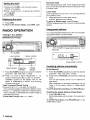
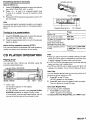
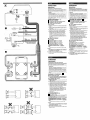
3-251-499-ll(1)
FM/AM Compact Disc Player
CDC.2137
OPERATING INSTRUCTIONS
INSTRUCCIONES DE MANWO
MODE D’EMPLOI
--
DIGITAL AUDIO
Owner’s Record
visit us on the-internet at
call toll free 1-800-BUY-AIWA
(United States only)
0 2003 Sony Corporation
For your convenience, record the serial number (you will find
them on the bottom side of your set) in the space provided
below. Please refer to them when you contact your AlWA
dealer in case of difficulty.
Model No. CDC-Z137
Serial No.
PRECAUTIONS
Use only in a 12-volt DC negative-ground electrical
system.
Disconnect the vehicle’s negative battery terminal
while mounting and connecting the unit.
When replacing the fuse, be sure to use one with an
identical amperage rating. Using a fuse with a higher
amperage rating may cause serious damage to the
unit.
Do NOT attempt to disassemblethe unit. Laser beams
from the optical pickup are dangerous to the eyes.
Make sure that pins or other foreign objects do not get
insidethe unit; they may cause malfunctions, or create
safety hazards such as electrical shock or laser beam
exposure.
When your vehicle has been parked in direct sunlight
resulting in a considerable rise in the temperature
inside, allow the unit to cool off before operating it.
Keep the volume at a level at which you can hear
outside warning sounds (horns, sirens, etc.).
NOTE
This equipment has been tested and found to comply
with the limits for a Class B digital device, pursuant to
Part 15 of the FCC Rules. These limits are designed to
provide reasonable protection against harmful
interference in a residential installation.
This equipment generates, uses, and can radiate radio
frequency energy and, if not installed and used in
accordance with the instructions, may cause harmful
interference to radio communications. However, there
is no guarantee that interference will not occur in a
particular installation. If this equipment does cause
harmful interference to radio or television reception,
which can be determined by turning the equipment off
and on, the user is encouraged to try to correct the
interference by one or more of the following measures:
- Reorient or relocate the receiving antenna.
- Increase the separation between the equipment
and receiver.
- Connect the equipment into an outlet on circuit
differentfrom thatto which the receiverisconnected.
- Consult the dealer or an experienced radioFV
technician for help.
TABLE OF CONTENTS
BASIC OPERATION, AUDIO AND CLOCK
ADJUSTMENT .....................................................
RADIO OPERATION .................................................
CD PLAYER OPERATION
AUXILIARY EQUIPMENT .
OTHER FUNCTION ..................................................
TROUBLESHOOTING
MAINTENANCE........................................................
SPECIFICATIONS ....................................................
2
3
5
5
6
Note
Some buttons are assigned two or more functions.
For detailed descriptions, refer to the related pages.
CD Notes
&
Playing a defective or dusty CD can
cause dropouts in sound.
Hold CDs as illustrated.
Do NOT touch the unlabeled side.
Do NOT attach any seal, label or data protectionsheet
to either side of CD.
Do NOT expose a CD to direct sunlight or excessive
heat.
Wipe a dirty CD from the center outward with a
cleaning cloth.
Never use solvents such as benzine or alcohol.
This unit cannot play 3-inch (8 cm) CDs.
NEVER insert a 3-inch CD contained in the adapter or
any irregularly shaped CD.
The unit may not be able to eject it, resulting in a
malfunction.
Resetting the unit
Before operating the unit for the first time or after
replacing the car battery, you must reset the unit.
Press the reset button with a pointed object such as a
pencil.
Reset button
CAUTION
Modifications or adjustments to this product, which are
not expressly approved by the manufacturer, may void
the user’s right or authority to operate this product.
be read by this unit. However, NEVER use a CD-R or
CD-RW that contains no data or data in the wrong
For installationand connections,referto-theseparate
“INSTALLATION AND CONNECTIONS:
1 ENGLISH
Note
Pressing the reset button will erase the clock and some
memorized functions.
BASIC OPERATION,
AUDIO AND CLOCK
ADJUSTMENT
Press SEL repeatedly to select the mode to be
adjusted.
Pressing SEL cycles through the modes. The
selected mode's indicator appears.
Turn Jog dial to increase/decrease the level or to
select onloff for the selected mode.
PWRIAT
I
Note
Adjust the level or select on/off within 5 seconds, or the
selected mode will return to previous state.
sELJog dial (PUSH-SOURCE)
Alianina the source levels
(Source Level Adjuster)
r
,
I DSPL
TU(TUNER)
+I-
Turning the unit onloft
Press PWWAlT to turn on the unit. The unit also turns
on when you insert a CD.
Press and hold PWWAlT until the unit turns off.
Most operationsdescribed in this manual requirethe
unit to be turned on before starting the operation,
unless explicitly stated otherwise.
Note
Adjust the level within 5 seconds, or the selected mode
will be canceled.
Restoring the factory settings
Chanaina the source mode
1 Press Jog dial (PUSH-SOURCE).
Pressing Jog dial (PUSH-S0URCE)cyclesthrough
source modes in the following order:
TUNER (FMlIFM2/FMB/AMl/AM2) + CD* + AUX
f
Volume may vary each time you change the source
mode. In this case, you can align each source mode's
volume to almost the same level.
1 Press Jog dial (PUSH-SOURCE) or TU (TUNER)
repeatedly to select the desired mode.
2 Press DSPL while pressing SEL.
"LA 0 appears on the display.
3 Turn Jog dial to adjust the level.
I
* " C D does not appear in the display when there is no
CD in the unit.
1 Turn off the unit.
2 Press and hold DSPL until "LA --" appears on the
display.
Note
You can restore the factory settings only for VOL,
BASS, TRE, BAL, FAD, and H-BASS, and aligned
source volume levels.
Adiustina the volume
Setting the beep tone
1 Turn Jog dial.
1 Turn off the unit.
2 Press and hold SEL until "bEEP appears on the
.a
VOLUME indicator appears.
display.
Muting the sound
1 Press PWFJAn briefly.
3 Turn Jog dial to select on (level indicators appear)
or off (level indicators disappear).
4 PressSEL.
A T indicator flashes.
To restore volume, briefly press PWWATT again.
Adiustina sound
You can select the following modes for adjusting sound
depending on the music you listen to: BASS (low
frequencies), TRE (high frequencies), BAL (leftlright),
FAD (fronil rear) and H-BASS (high bass).
ENGLISH
2
Setting the clock
1 Press and hold DSPL until the clock indicator
flashes in the display.
2 Press + (to set hour) or- (to set minute), and then
turn Jog dial.
3 Press DSPL.
Displaying the clock
1 PressDSPL.
To return t o the former display, press DSPL again.
RADIO OPERATION
Tuning in to a station
Monaural m o d e
When signals become weak, or FM reception becomes
poor, the unit automatically switches to Monaural mode
to reduce noise.
Local m o d e
Local mode allows you to tune in only to strong stations
during Seek Tuning.
1 Press LO before you start seek tuning.
"LOCAL" appears on the display.
To return t o Distant mode, press LO again.
"LOCALdisappearsand theunittunesin toall receivable
stations.
Using preset stations
You must preset stations before you can tune in astation
using preset station number buttons.
(SeeWManual Tuning)
-0
+/+/-
I
TU (TUNER) Preset station buttons 1 to 6
PS/A.ME
TU (TUNER)
Local indicator
Stereo indicator
Preset station number
Presetting stations automatically
Band indicator Frequency
TUNER
indication
indicator
1 Press TU (TUNER) repeatedly to select the desired
band (FMI , FM2, FM3, AMI, or AM2).
2* Press + (to move to higher frequencies) or - (to
move to lower frequencies) to tune in to a station.
"STEREO appears on the display when an FM
station is broadcasting in stereo, and receiving
conditions are good.
*Seek Tuning and Manual Tuning
Press and hold + or - until seek Tuning starts.
The unit locatesastation automatically (SeekTuning).
Press + or - repeatedly to search for a desired station
while increasing or decreasing the frequency step by
step (Manual Tuning).
To stop Seek Tuning, press + or - again.
3 ENGLISH
(Auto Memory)
1 Press TU (TUNER) repeateoly to se ect the oes red
band (FM1, FM2 FM3, AM1, or AM2)
2 Press and n o d PS/A.ME Jnti automatic presett ng
starts
Tne unit aJtomatical y stores LP to 6 stations for
each band
After complet on of aLtomatic presetting tne n, t
u n e s n to the stat on stored on preset station
b Jnon 1
To cancel automatic presetting, press PS/A.ME again
Checking t h e preset stations (Preset Scan)
1 Press PS/A.ME or ef y
Each preset station w 11 be tuned in for 5 seconds n
oroer
To cancel Preset Scan, press PS/A.ME aga n or any
preset stat on oJtton
Presetting stations manually
Labeled-side up
(Manual Memory)
1 Press TU (TUNER) repeatedly to select the desired
band (FMI, FM2, FM3, AMI, or AM2).
2 Press + or - to tune in to a desired station (see
"Tuning in to a station'' as well for another tuning
method).
3 Pressand hold the desired preset station button until
the unit beeps.
Track number
Note
A newly preset station replaces the station on the same
band that was previously stored on that preset station
button.
Elapsed playing time
Press
To
..
Tuning in to a preset station
Eiect a CD
1 Press TU (TUNER) repeatedly to select the desired
band (FM1, FM2, FM3, AM1 or AMZ).
2 Press the preset station button on which the desired
station is stored.
Active tuning reception control (ATRC)
The unit automatically suppresses FM noise caused by
vehicle movement, and maintains sound quality.
CD PLAYER OPERATION
Playing a CD
You can play CDs, CD-Rs and CD-RWs using the
procedure described below
INT
REPl
SHUF
1 Insert a CD.
CD indicator appears on the display.
CD play starts.
If a CD is already inserted, press Jog dial (PUSHSOURCE) repeatedly to select CD play mode.
In normal play, when the last trackfinishes, the unit
returns to the first track and continues to play.
CD indicator
A
to the next track
W/W
Go back to the beginning
of the current track
Each extra press skips
backward one extra track
Locate a specific point in
a track
Mi44
SkiD
Press and hold Mi44
or W / W until you find
the point.
Note
When you play a CD that is already inserted, CD play
starts at the point where it stopped the previous time.
A newly inserted CD starts from the first track.
A CD-R or CD-RW may take some time to start playing
back, but this is not a malfunction.
If a CD-R or CD-RW with no data is inserted, " E 0 3 will
appear in the display. The unit cannot play such discs.
lntro Play
You can locate a desired track by monitoring the first 10
seconds of all the tracks on a CD.
1 Press INT during CD play.
"INTRO appears on the display.
2 Press INT again when the desired track is played.
The unit returns to normal CD play.
One track Repeat Play
You can play a track repeatedly.
1 Press REPl during CD play.
"REPI" appears on the display.
To cancel One track Repeat Play, press REPl again.
ENGLISH
4
Displaying the VU level indicator
Shuffle Play
You can play all the tracks in random order.
1 Press SHUF during CD play.
"SHUF appears on the display.
To cancel Shuffle Play, press SHUF again
1 Turn off me unit
2 Press and nolo PS until "VII" appears n the oisp ay.
3 TJrn Jog dial to select on (leve naicators appear)
or off (level ind cators d sappear)
Note
During Shuffle Play, pressing HI allows you to skip
only to the beginning of the current track, not to the
previous track.
AUXILIARY EQUIPMENT
Listening to a cassettelMDlMP3 portable
Dlaver or other eauiDment
4 Press PS.
TROUBLESHOOTING
Error code
In the following cases the corresponding error code
indication appears. Follow the suggestions below to
solve such problems.
ED3
You can listen to equipment connected to the unit. Refer
to the operating instructions for the corresponding
equipment for more detailed information.
Be sure to remove inserted CDs to prevent possible
damage to the unit before connecting the equipment.
Focuserror. Checkthatthe CD is loadedproperly
(right side up, etc.), and the CD contains valid
data.
Reset button
If a CD does not operate properly, press the reset button
with a pointed object such as a pencil, etc. Note that all
your settings will be erased if this button is pressed.
Reset button
Jog dial'(PUSH-SOURCE)
AUX j k k
1 Connectacassette/MD/MP3portableplayerorother
equipment to the unit's AUX jack (3.5 mm dia.).
2 Press Jog dial (PUSH-SOURCE) repeatedly until
"AUX appears on the display.
During AUX mode, the clock display appears.
OTHER FUNCTION
SEL
I 6s
Jog dial (PUSH-SOURCE)
Setting the dimmer of the display
1 Press and hold SEL until " D appears in the display.
2 Turn Jog dial to select "0 (bright)" or "1 (dimmed)."
MAINTENANCE
Cleaning the front panel
Wipe the surface with a soft, dry cloth. Do not use liquid
cleaners or aerosol cleaners.
SPECIFICATIONS
RADIO SECTION
(FM)
Frequency Range: 87.5 MHz - 108 MHz
Usable Sensitivity: 12.7 dBf
50 dB Quieting Sensitivity: 17.2 dBf
IF Rejection: 100 dB
Frequency Response: 30 Hz - 15,000 Hz
SIN Ratio: 70 dB
Stereo Separation: 35 dB at 1 kHz
Alternate Channel Selectivity: 90 dB
Capture Ratio: 3 dB
(AM)
Frequency Range: 530 kHz - 1,710 kHz
Usable Sensitivity: 30 VV (30dB)
CD SECTION
Frequency Response: 17 Hz - 20 kHz +O/-3 dB
Dynamic Range: More than 85 dB
Channel Separation: More than 60 dB
S/N Ratio: More than 90 dB
WowlFlutter: Unmeasurable
AUDIO SECTION
Max. Power Outpuk45 W x 4 channels
AUX input
Input sensitivity (load impedance) AUX 300 mV
(10 @4
GENERAL
Power-Supply Voltage: 14.4 V (11 to 16 V
allowable), DC, negative ground
Load Impedance: 4 R
Tone Control:
Bass~10dBatlOOHz,TrebleilOdBat10kHz
Preamp Output Voltage (load impedance): 2.2 V
(10
Installedsize: I82 (W) x 53 (H) x 155 (0)
mm
(7 (W) x 2 '18 (H) x 6 l/8 (D)inches)
w
Specificationsand external appearance are subject to
change without notice due to product improvement.
ENGLISH
6
LIMITED WARRANTY
Aiwa Strategic Accounts Partnership Inc. (“Aiwa”) warrants to the original consumer purchaser that this
product is free of detects in material and workmanship at the time of purchase.
WARRANTY PERIODS
During the applicable LABOR warranty period, Aiwa will pay labor and service charges for the repair of
defects or, at its option, will replace a defective product with a new or remanufactured equivalent product.
During the applicable PARTS warranty period, Aiwa will supply at no charge new or rebuilt replacement
parts in exchange for defective parts. However, after the LABOR warranty period, all labor and service
charges are your responsibility. Replacement parts are warranted for the remainder of the original PARTS
warranty period.
The LABOR and PARTS warranty periods for your product are listed below. All warranly periods
commence with the purchase date.
LABOR
PARTS
Car Audio
1 year
1 year
WHO PERFORMS AIWAS WARRANTY?
Aiwa’s warranty obligations must be performed by an Aiwa Authorized Service Center. For the name of the
Aiwa Authorized Service Center nearest to you call toll free 1-800-289-2492 (1-800-BUY-AIWA).
WHAT YOU MUST 00
To obtain warranty performance, you must take the product, or deliver the product freight prepaid, to an
Aiwa Authorized Service Center. If shipped, the product must be packaged so that it is protected from
possible shipping damage. You must pick up the product when warranty performance is completed or, if
you choose, and the product was received by the Service Center during the LABOR warranty period, the
repaired product will be returned to you freight prepaid. You must present to the Service Center, or include
with your shipment, a dealer’s bill of sale, or other original evidence, showing the date and place of
purchase and describing the product purchased. Be sure to include your return address and daytime
telephone number where you can be reached should the need arise.
WHAT THE WARRANTY DOES NOT COVER
This warranty does not cover (1) products purchased outside of the U.S.A.; (2) product set-up, adjustment
of controls, repair of antenna systems outside the unit; (3) removal or reinstallation, batleries, carrying
case, AC adapters and other accessories packaged with the product; (4) defects occurring after purchase
due to repair or service other than by an Aiwa Authorized Service Center, product modification, accident,
misuse, abuse, or negligence: or (5) reception problems caused by signal conditions, or cable or antenna
systems outside the unit. This warranty will not apply if the serial number of the unit has been altered or
removed.
REPAIR OR REPLACEMENT AS PROVIDED IN THIS WARRANTY IS THE PURCHASER’S EXCLUSIVE
WARRANTY REMEDY. IMPLIED WARRANTIES, INCLUDING THE WARRANTIES OF MERCHANTABILITY
AND OF FITNESS FOR A PARTICULAR PURPOSE, SHALL NOT EXTEND BEYOND THE DURATION OF THE
APPLICABLE PARTS WARRANTY PERIOD. IN NO EVENT SHALL AlWA BE LIABLE FOR INCIDENTAL OR
CONSEQUENTIAL DAMAGES IN CONNECTION WITH THISPRODUCT. ,Some states do not allow limitations
on how long an implied warranty lasts or the exclusion or limitation of incidental or consequential damages,
so the above limitations or exclusion may not apply to you. This warranty gives you specific legal rights.
and you may also have other rights which may vary from state to state.
IF YOU NEED HELP: For the latest in Product Information, Parts, Service Center listings and F.A.Q.
information visit us on the web at www.us.aiwa.com or call
1-800-BUY-AIWA.
For further Aiwa information, please call 1-800-BUY-AIWA.
Visit us on the Internet at www.us.aiwa.com
D 455724401
http:llwww.aiwa.coml
Sony Corporation
Printed in Thailand
A\i!!!
INSTAL LATlO N A N D C 0NNECTI 0 NS
INSTALACION Y CONEXIONES
INSTALLATION ET CONNEXI ONS
SUPPLIED MOUNTING HARDWARE FOR
INSTALLATION + W
MATERIEL DE MONTAGE FOURNI POUR
L'INSTALLATION + W
INSTA L LAT I0NS
INSTA L LATlO N
The installation scenario described in this manual
assumes that you have a typical car. If your specific car
requires any adjustments or modifications, consult your
nearest AlWA car audio dealer.
Le scenario d'installation indique dans ce manuel
presuppose une voiture typique. Si votre voiture exige un
ajustement ou une modification, consultez le revendeur
de chaine audio automobile AlWA le plus proche.
PRECAUTIONS
PRECAUTION
*This unit is designed for negative-ground, 12-V DC
operation only.
Beforestarting installation, make sure the ignition switch
is set to OFF and disconnect the ground terminal of the
car battery to avoid short-circuiting.
Install the unit where it will not hamper the operation of
the vehicle.
Install the unit where it will not injure the passenger if
there is a sudden stop, like an emergency stop.
Avoid installing the unit where it would be subject to high
temperatures caused by direct sunlight or hot air from
the heater, or where it would be subject to dust, dirt or
excessive vibration.
Use only the supplied mounting hardware, for a safe
and secure installation.
Sony Corporation @ 2003 Printed in Thailand
3-251-494-11 (2)
PREINSTALLATIONS + DZ
If there is installation hardware for another receiver
already in the dashboard, it must be removed.
Before installingthe unit in the dashboard
Remove the trim plate from the unit + 0
FIX (fixed panelktype model Remove the trim plate
0 by pushing the upper and lower parts of the plate in
the direction of the arrow.
As for the DFP (DetachableFront Panel) -type model
and FLAP (flap panelktype model, the trim plate is
separately packed at the factory.
Remove the installation sleeve +
Insert the levers @ along each groove on both sides of
the unit to unlock the installation sleeve 0and pull the
sleeve to detach it from the unit.
BASIC INSTALLATIONS +
Installation in the dashboard
Note that the Installation shown is a typical example.
For some car types you may need to make adjustments
or modifications to install the unit. If your car is of such
type, consult your nearest AlWA car audio dealer.
Mounting-angle adjustment
The mounting angle should be 30 degrees or less from
horizontal.
Caution on installation without using
the sleeve + IE
Be sure to use the supplied screws @
shown in LK toattach the mounting brackets
@ (not supplied).
Cet appareil est conqu uniquementpour lefonctionnement
sur courant continu 12 V, masse negative.
Avant de commencer I'installation, verifiez que le
commutateur d'allumage est regle a OFFet deconnectez
le prise de masse de la batterie auto pour eviter tout
court-circuit.
lnstallez I'appareil a un endroit OD il ne genera pas le
fonctionnement de la voiture.
lnstallez I'appareil a un endroit ob il ne blessera pas le
passager, en cas d'arr6t brutal, par exemple un arr6t
d'urgence.
Evitez d'installer I'appareil un endroit en plein soleil ou
sous I'air chaud du chauffage, ob il sera sournis a des
temperatures elevees, ou bien a un endroit ou il sera
soumis a une poussiere,de lasaleteou deforlesvibrations.
Utilisez seulement le materiel de montage fourni pour
assurer une installation s h e et solide.
PREPARATIFS POUR L'INSTALLATION
-+ DZ
S'il y a deja du materiel de montage pour un autre
recepteur dans le tableau de bord, il doit 6tre retire.
Avant d'installer I'appareil dans le tableau de bord
Retirez la plaque d'ajustementde I'appareil + 0
Modhle de type FIX (panneau fixe) Retirez la plaque
d'ajustement 0 en poussant les parties haut et bas de
la plaque dans le sens de la fleche.
Comme pour le modble de type DFP (panneauavant
amovible) et le modele de type FLAP (panneau
basculant), la plaque d'ajustement est emballee
separement a I'usine.
Retirez le manchon d'installation + H
lnserez les leviers @ le long dechaquecanneluresur les
deux cBt6s de I'appareil pour debloquer le manchon
puistirezsur le manchon pour ledetacher
d'installation 0,
de I'appareil.
INSTALLATION DE BASE +
Installation dans le tableau de bord
Pour cettains types de voiture, il faudra peut-6tre faire
des ajustements ou modifications pour installer I'appareil.
Si c'est le cas pour votre voiture, consultez le revendeur
de chaines audio automobiles AlWA le plus proche.
Ajustement de I'angle de montage
L'angle de montage doit 6tre de 30' ou moins de
I'horizontale.
Precaution pour I'installation sans
manchon +
Utilisez les vis fournies @ indiquees dans
pourattacher lesfixations de montage @ (non
fournies).
ACCESORIOS DE MONTAJE SUMINISTRADOS
PARA LA INSTALACION + W
INSTALACION
La instalaciondescritaa lo largo de este manualpresupone
que tiene un coche normal. Si su coche requiere ajustes
o modificaciones, consulte con su concesionario de audio
para coches de AlWA mas cercano.
PRECAUCIONES
Este aparato fue disefiado para una conexion a tierra
negativa y funciona con una CC de 12 V.
Antes de empezar la instalaci6n, compruebe que el
interruptor de encendido esta en OFF y desconecte el
terminal a tierra de la bateria de coche para evitar que
se produzca un cortocircuito.
lnstale el aparato donde no moleste el funcionamiento
del vehiculo.
lnstale el aparato en un lugar donde no provoque
heridas a 10s pasajeros por un frenado repentino, como
en el caso de un frenado de emergencia.
Evite instalar el aparato donde quede expuesto a altas
temperaturas provocadas por 10s rayos directos del sol
o el aire caliente de la calefaccion o donde pueda estar
expuesto al polvo, suciedad o vibraciones excesivas.
Utilice solo 10s accesorios de montaje suministrados,
para una instalacion firme y segura.
INSTALACION PREVIA + DZ
Si yase han instalado accesorios para instalacion deotro
aparato en el tablero, debera desmontarlos.
Antes de instalar el aparato en el cubretablero
Desmonte la placa de adorno del aparato + 0
Modelo de tipo FIX (panel fijo) Desmonte la placa de
adorno 0 empujando las partes superior e inferior de
la placa en el sentido de la flecha.
* P a r a el modelo de tipo DFP (Panel frontal
desmontable) y el modelo de tipo FLAP (Panel de
aleta), la placa de adorno se empaqueta por separado
en la fabrica.
Desrnonte el manguito de instalacion + H
lnsette las palancas @ a lo largo de cada ranura en
ambos lados del aparato para destrabar el manguito de
instalacion 0 y tire del manguito para desmontarlo de la
del aparato.
.
INSTALACION BASICA +
lnstalacion en el tablero
Tenga en cuenta que la instalacion que se describe es a
modo de ejemplo. Para algunos modelos de coche,
puede ser necesario hacer ajustes o modificaciones
para instalar el aparato. Si su coche es de este tipo,
consulte con su concesionario de audio para coches de
AlWA mas cercano.
Ajuste del dngulo de rnontaje
El angulo de montaje debe ser de 30 grados o menos de
la horizontal.
utilizar el manguito --f
Se deben utilizar siempre 10s tornillos
suministrados @ que aparecen en
para
instalar las rnensulas de montaje
(no
suministradas).
6
CONNECTIONS
CONNEXIONS
PRECAUTIONS
PRECAUTIONS
Precaution on making connections
Before connecting, make sure that the ignition switch is
set toOFF, and remove the ground terminal of the battery
to protect the unit and your car from damage.
Precautions pour les connexions
Avant le raccordement, verifiez que la cle d'allumage est
sur OFF, et debranchez le prise de masse de la batterie
pour proteger I'appareil et votre voiture des dommages.
Caution
I
Make the connections correctly, as illustrated in the
connection diagram
Do not connect the negative 0 cord of each speaker
wire to a common point When replacing the fuse, be
sure to use a fuse of the same rated amperage Use
of a fuse of a higher rating may cause serious
CONNECTION DIAGRAM +
DIAGRAMME DE CONNEXION +
From the car antenna
To the input jack of the optional power
amplifier (for the rear channel)
H To the wiring of the vehicle
Colors of leads
3
Black(ground lead to beconnected tovehicle [metal]
body )
3 Red (ACC lead to be connected to the terminal from
which power is supplied when the ignition switch is
set to ACC )
@ Yellow (battery lead to be connected to the backup
terminal from which power is always supplied )
@ Blue (power antenna lead to be connected to the
terminal of the control relay switch for a vehicle
equipped with a fully automatic power antenna
This lead is not used for a vehicle with a manual
antenna or a switch-operated power antenna If
you will use the optional power amplifier with the
unit, connect this lead to the remote terminal of the
amplifier )
(Max supply current 0 1 A)
0 Speaker connections
Colors of leads
Whitewhite & Black, Front left @/@
Gray/Gray & Black, Front right @/O
VioleWiolet & Black, Rear right @/O
GreeniGreen & Black, Rear left $10
4-SPEAKER CONNECTIONS +E
2-SPEAKER CONNECTIONS +
Note
Insulate the end of the unused lead with a piece of tape
Notes
Use speakers with an impedance of 4 to 8 ohms and
with adequate power-handling capacities Othewise,
the speakers may be damaged
Do NOT connect the speakers in parallel
Do NOT connect the terminals of the speaker system to
the car chassis
CONEXIONES
PRECAUCIONES
Precauciones al hacer las conexiones
Antes de conectar,confirmeque el interruptordeencendido
esta en OFF y desmonte el terminal a tierra de la bateria
para proteger el aparato y su coche contra daiios.
Haga las conexiones correctamente, tal como se
describe en el diagrama de conexiones.
No conecte el cable negativo 0 de cada cable de altavoz
a un puntocomun. Cuandocambieel fusible, utilice siempre
uno del mismo amperaje nominal. El us0 de un fusible de
mayor regimen puede provocar daiios importantes en el
aparato.
DIAGRAMA DE CONEXIONES
61
Effectuez les connexions correctement, comme
indique sur le diagramme de connexion.
Ne raccordez pas le cordon negatif O de chaque fil
de haut-parleur Aun pointcommun. Au remplacement
du fusible, utilisez un fusible a amperage nominal
identique. L'emploi d'un fusible a amperage plus
eieve Deut serieusement endommager I'appareil.
+
De la antena del coche
A la toma de entrada del amplificador de
potencia opcional (para el canal trasero)
H Al cableado del vehiculo
Colores de 10s cables
0 Negro (cable a tierra a conectar a la carroceria del
vehiculo [metal] )
@ Rojo (cableACC aconectaralterminalque recibe electrica
cuando el interruptor de encendido esta en ACC )
0 Amarillo (cable de bateria a conectar al terminal de
reserva con un flujo permanente de electricidad )
@ Azul (cable de antena motriz a conectar al terminal
del interruptor del rele de control para un vehiculo
equipado con antena motriz totalmente
automltica Este cable no se debe utilizar en un
vehiculo con antena manual o antena motriz que
funcione mediante interruptor Si utiliza el
amplificador de potencia opcional en esta unidad
conecte este cable al terminal remoto del
amplificador )
(Corriente maxima 0 1 A)
0 Conexiones de altavoces
Colores de 10s cables
BlancolBlancoy negro,parte frontal izquierda @I@
GrislGris y negro parle frontal derecha $10
VioletaNioleta y negro,parte posterior derecha @/@
VerdeNerde y negro,parte posterior izquierda @/Q
CONEXIONES PARA 4 ALTAVOCES +E
CONEXIONES PARA 2 ALTAVOCES +
Nota
Aisle la punta del conductor sin usar con cinta
Notas
Utilice altavoces con una impedancia de 4 a 8 ohmios
y con suficiente capacidad electrica De lo contrario
puede daiiar 10s altavoces
NO conecte 10s altavoces en paralelo
NO conecte 10s terminales del sistema de altavoces al
chasis del coche
De I'antenne du vehicule
0 A la prise d'entree de I'amplificateur de
puissance en option (pour le canal
arriere)
H Vers le ciblage du vehicule
Couleurs des fils
0 Noir (fil de mise la terre a raccordera lacarrosserie
[metal] du vehicule.)
raccorder a la prise a partir de
laquelle la puissance est fournie quand la cle
d'allumage est reglee sur ACC.)
@ Jaune (filde batteriearaccorderalaprisedesecours
de laquelle I'alimentation se fait toujours.)
@ Bleu (fil d'antenne electrique a raccorder A la prise
du commutateur de relais de commande pour un
vehicule Bquipe d'une antenne electrique
entierement automatique. Ce fil n'est pas utilise sur
les vehicules antenne manuelle ou antenne
electrique operee par commutateur. Si vous
souhaitez utiliser I'amplificateur de puissance en
option avec cet appareil, raccordez ce fil a la prise
de telecommande de I'amplificateur.)
(Courant d'alimentation maxi. 0,1 A)
@ Rouge (fil ACC
0 Raccordement des enceintes
Couleurs des fils
BlanclBlanc et Noir; Avant gauche @/@
Gris/Gris et Noir; Avant droite 810
VioleWiolet et Noir; Arriere droite 8 / O
VerVVert et Noir; Ar '
RACCORDEMENT A 4
RACCORDEMENT A 2
Remarque
lsoler I'extremite du fil inutilise avec du ruban.
Remarques
Utilisez des enceintes a impedance de 4 a 8 ohms et
puissance nominale adequate. Sinon elles seront
endommagees.
Ne raccordez PAS les enceintes en parallele.
Ne raccordez PAS les prises du systeme d'enceintes
au chassis de la voiture.