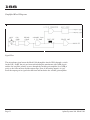
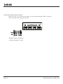
1
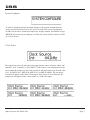
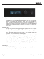
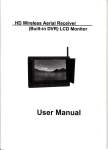
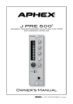
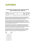
Model 188
188
Remote Controlled 8 Channel Microphone
Preamplifier
Instruction Manual
P/N 188-3200
Preliminary Rev 1
Released 01/23/09
Manufactured by
Aphex Systems Ltd.
11068 Randall St.
Sun Valley, CA 91352
USA
Copyright 2009 Aphex Systems Ltd. All rights reserved.
Produced by Wayne LaFarr
Aphex Systems Ltd. Model 188
Page 1
188
A MESSAGE FROM THE PRESIDENT
Dear Aphex Customer,
Congratulations on your purchase of the Model 188 Remote Controlled Microphone Preamplifier. Years of
research and development were required to overcome the hurdles that similarly purposed products do not even
address. Since the introduction of our first remote controlled preamplifier, the Model 1788 and its successor the
Model 1788A, we have learned much from hundreds of high profile applications. While the Model 188 does not
have all the features that are in the Model 1788As, it does have the primary functionality and performance at a
fraction of the cost.
The Model 188 was designed primarily as an integral part of the Anaconda Digital Snake System. Our listening
tests as well as tests by respected engineers have confirmed that the Model 188 is an excellent sounding preamplifier in its own right. The value of it is so much higher because it is so easily remote controllable. It can be
controlled by the Model 1788AR-C hardware remote controller, PC or MAC software.
We are extremely pleased that you have joined the elite of the audio world.
Very truly yours,
Marvin Caesar
President
Safety Declarations
CAUTION: For protection against electric shock, do not remove the cover. No user serviceable parts inside.
WARNING: This equipment has been tested and found to comply with the limits for a Class A digital device pursuant to Part 15
of the FCC Rules. These limits are designed to provide reasonable protection against harmful interference when the equipment is
operated in a commercial environment. This equipment generates, uses, and can radiate radio frequency energy and, if not installed
and used in accordance with the operating guide, may cause interference to radio communications. Operation of this equipment
in a residential area is likely to cause interference in which case the user will be required to correct the interference at his own
expense.
The user is cautioned that changes and modifications made to the equipment without approval of the manufacturer could void the
user’s authority to operate this equipment.
It is suggested that the user use only shielded and grounded cables to ensure compliance with FCC Rules.
|
Aphex Systems Ltd. Model 188
Page 2
188
Table of Contents
1.Introduction
2.Quick Start
Front Panel LCD Display and Rotary Encoder/Switch
Front Panel Screens
3. Rear Panel
4. Model 188 block diagram and signal flow
5. Installation
6. Functions in Detail
Aphex Systems Ltd. Model 188
Page 3
Introduction
188
Why remote controlled preamplifiers?
Locating the mic preamplifier as close as possible to the microphone eliminates the long cable runs at mic level.
Induced noise would be amplified. In addition, capacitance and resistance in that long cable run would affect
the performance of the microphone.
Transformer splitters are only effective in isolating ground. The impedance from all the preamplifiers connected
to the system as well as the cabling combine to load down the output of the microphone. For example- most
microphones are designed to drive between 1200 and 1500Ω loads. If a microphone is connected to three preamplifiers, the input impedance is 500Ω. The sonic effects are reduced frequency and transient response, and
higher noise. The increase in audio quality when the microphone is driving an ideal load is dramatic. The 188
acts like an active splitter with one analog and two digital outputs..
Once you have line level signal from the remote preamplifier make sure that you do not put that signal through
another preamplifier. Almost all consoles switch in a pad in front of their preamplifiers and label the input as
‘line’. If the trim pot still controls level, you are going through a preamplifier. It is best to use an insert return
for an analog line level signal. You will be amazed at how much better everything sounds!
If you are using a digital console without any analog input other than a preamplifier, we strongly recommend
converting the output of the remote preamplifier to digital. We designed a high quality A/D into the Model 188
for that purpose.
The Model 188 and its big brother the Model 1788A fulfill all the requirements for a remote controlled preamplifier- great audio, easy to control, no glitches, pops or zipper noise, and multiple outputs.
Aphex Systems Ltd. Model 188
Page 4
188
Quick Start
Rotary Encoder and Switch
Rotate the encoder clockwise or counterclockwise to scroll between screens. Press the encoder to make the cursor appear within a screen. Rotate the encoder to move the cursor to
the value or status to be changed and press to select, the cursor will start blinking. Rotate
the encoder to change the value or status. Press the encoder to save the value or status.
Start Up
The first screen shows the firmware version that is loaded into the
Model 188. It is a good idea to check the Aphex website occasionally to see if there are any updates. Updating the firmware is covered in section----
Aphex Systems Ltd. Model 188
Page 5
188
Metering
This screen shows a twelve segment peak level meter for each channel.
When there is an overload the clip on that channel is indicated with a “!”.
When the unit receives a command from a remote controller, “RC” will
light for half a second. We recommend that this screen be selected when
set up is complete.
Channel Status and Input Gain
There is one screen for each of the eight channels. Each screen indicates
Channel number, gain, status for Polarity Reverse, Pad, Low Cut Filter, and
Phantom Power functions. A check mark under the function indicates that it
is active. A dash indicates that it is not active.
The Input Gain is adjustable from 26 to 65dB.
Aphex Systems Ltd. Model 188
Page 6
188
System Configure
In order to safeguard against unwanted changes to the system configuration, the
rotary encoder must be pressed in for several seconds. The system configuration
includes clock source, format and sample rate, display contrast, Net Number assign,
DHCP/IP select and system configure exit. The first screen after the encoder is held
in is Clock Source.
Clock Source
Pressing the encoder will make the cursor appear under source selection- either “Int”
(internal), “Ext” (external), or “Ext SMUX”. If the source is set to Internal move the
cursor under the sample rate. Press the encoder in and then rotate to the desired value
(44.1, 48, SMUX 44.1, SMUX 48, SMUX 88.2 or SMUX 96kHz). The rate that is
selected will appear on the Word Clock output. If the source is set to External, the
sample rate will appear in the screen if there is a valid clock input.
Aphex Systems Ltd. Model 188
Page 7
188
Contrast Adjust
Press encoder in and then rotate clockwise for more contrast,
counter-clockwise for less contrast.
Net Number
The Net Number identifies the particular unit within a system.
Note: There must be only one unit assigned to one Net Number
otherwise the Remote Control and metering will be unpredictable.
DHCP/FIXED IP
DHCP requires a router which will ‘serve’ an IP address dynamically. Fixed IP forces the address
that is programmed into the unit and modified by the Net Number. The letter ‘D’ will be in front of
the IP address when DHCP is selected and the letter ‘F’ will be in front of the IP address when Fixed
IP is selected. The fixed IP addresses range from 192.168.1.64 for Net Number 001 to 192.168.1.192
for Net Number 128. If these addresses are not compatible with your network, please contact Aphex.
Note: Power must be cycled off and on to commit these changes.
Aphex Systems Ltd. Model 188
Page 8
188
Exit Configure
Press the encoder in and the display will change to the
metering screen.
Rear Panel
Microphone Inputs
Each microphone input is a locking female XLR (pin #1 ground, pin # 2 ‘+’ and
pin # 3 ‘-‘). Maximum input level is +21dBu with Pad engaged and the input
gain at 26dB.
Line Level Output
The channel outputs appear on a 25 pin D-Sub female connector using the Tascam analog standard pin out. Maximum output level is fixed at +21dBu. Note:
The analog output of each channel can be internally ( See page 15) selected to
be either ‘post’ or ‘pre’ variable gain amplifier. In the ‘post’ mode the output
will be affected by the Pad, Low Cut and Polarity Reverse as well as the variable gain amplifier. In the ‘pre’ mode the output will be affected by everything
except the variable gain amplifier. The ‘pre’ mode is useful to feed a monitor
console.
ADAT Outputs 1 and 2
Each Toslink connector will output standard ADAT (audio channels 1 through
8) when SMUX is not selected. When SMUX is selected ADAT Output 1 will
have audio channels 1, 2, 3 and 4; and ADAT Output 2 will have audio channels
5, 6, 7 and 8.
Aphex Systems Ltd. Model 188
Page 9
188
SYNC
Standard BNC connectors with 75Ω terminations are provided for input (IN)
and output (OUT) of word clock. Input may be either word clock or AES. The
output will be word clock. The output will be the rate indicated on the front
panel.
LAN
Standard RJ-45 connector for Ethernet remote control as well as for future
downloads of firmware.
POWER
Standard IEC receptacle. The Model 188 has a switch mode power supply
which can accept any voltage from 90 to 260VAC and at either 50 or 60Hz.
GROUND LUG
Provides solid grounding point.
Page 10
Aphex Systems Ltd. Model 188
188
Simplified Block Diagram
Signal Flow
The microphone signal enters the Model 188 through the female XLR, through a switch
for the Pad (-26dB), the mic pre front end including the transformer with 26dB of gain
and the low cut filter, polarity reverse, through the variable gain amplifier (0 to 39dB of
gain), to the A/D converter and the output stage. Note: if the analog output is in “pre”
mode the output gets its signal after the front end but before the variable gain amplifire.
Page 11
Aphex Systems Ltd. Model 188
188
Installation
3.1 UNPACKING AND INSPECTING
Your Aphex product was carefully inspected and packaged at the factory prior to shipment.
The carton and packing materials are designed to protect the unit during shipment, but you
should inspect the carton and its contents for signs of physical damage before use. It is your
responsibility to file a damage claim with the shipper. We encourage you to save the original
packing materials in case you should ever need to ship this unit out for servicing.
3.2 MOUNTING
The Model 188 occupies 1RU (45mm or 1.75 inches) of a standard EIA equipment rack. Allow
at least an additional 3” to 4” of depth for connectors. Place the Model 188 in the desired rack
space and secure with the cushioned rack screws or equivalent hardware. Don’t position the
Model 188 directly above power amplifiers or power supplies that produce strong hum fields
or heat.
A word on rack mounting and ventilation
All electronic equipment will experience premature failure if operated at excessive temperatures.
The 188 requires adequate vented air space for proper cooling. What is adequate depends on
the ambient temperature, proximity of other heat producing equipment, and whether the air is
moving or still. It is always best to err on the safe side.
We recommend at least one free rack space be allowed between each 188. The space between
units may be filled with perforated filler panels, but we recommend against solid panels as they
will restrict air flow. In severe cases, such as very hot climates or tight, unventilated closets, a
rack-top exhaust fan may be required to keep the air moving. One of the best ways to know if you
have adequate ventilation for a stack of 188’s is to feel if the top unit’s chassis is substantially
hotter then the bottom unit. If so, you should provide better ventilation.
Ground Loops
The Model 188 uses a standard IEC power cord with a voltage range of 80 -280 VAC. The
appropriate mains plug for each country is normally shipped with each unit. However, if you
must install or replace the plug use the correct wiring code as follows
USA
Black = Live
White = Neutral
Green = Ground
Page 12
IEC/Continental
Brown = Live
Blue = Neutral
Yellow/Green = Earth
Aphex Systems Ltd. Model 188
188
Ground loops hardly ever cause problems within the 188 since it was designed with high
immunity. However, other equipment connected to the 188 may experience hum and noise from
a ground loop. Ground loops can occur when various interconnected equipment is powered from
separate AC circuits that are fed from opposite phases of the power feeder. Most service panels
assign odd numbered breakers to one phase and even to the other. Rooms that are powered from
more than one circuit can have outlets that are out of phase. Adjacent rooms may be powered
with opposite phase.
NOTE: If your system is plagued with ground loop troubles, you should try to get all the
equipment onto the same phase or use a local power isolation transformer.
3.5 MICROPHONE INPUT
The eight transformer coupled microphone INPUT CONNECTORS are locking female 3-pin
XLR’s wired with pin 2 positive.
3.6 OUTPUT CONNECTOR
DB-25 using the TASCAM standard for the eight transformerless impedance balanced
outputs .
DB-25 PIN CONFIGURATION (Analog OUTPUT)
The following chart is a pin configuration for the analog DB-25 connector.
This connector pinout matches the Tascam Analog DB-25 connector that has also been adopted
by many other manufacturers such as Mackie and Yamaha. Ready made cables can be purchased
to connect with other products, or to obtain a break-out to XLR plugs.
2 Positive (+)
3 Negative (-)
1 Shield (Ground)
Male
Female
Page 13
CH1
(+)
24
(-)
12
GND 25
CH2
10
23
11
CH3
21
9
22
CH4
7
20
8
CH5
18
6
19
CH6
4
17
5
CH7
15
3
16
CH8
1
14
2
Aphex Systems Ltd. Model 188
188
3.10 INSTALLING NEW FIRMWARE INTO THE 188
Aphex is always striving to improve the performance of its equipment. The firmware that was
programmed into your unit was the latest available at the time it was shipped. There may be
updates to the firmware that are made from time to time. Please check the Aphex website
at www.aphex.com to see if there are any updates made to the firmware from the time you had
purchased or last updated the unit.
Determine your current firmware version by going to the very first screen on the front panel
LCD. The loaded version will be at the lower right. NOTE: Do not attempt to download any
firmware designed for the 1788A into a Model 188 or vica versa.
DOWNLOAD PROCEDURE:
1. Connect an Ethernet cable from your computer to the Ethernet connector on the rear of the
188.
2. Power up the 188 while holding down the encoder. The LCD should be blank.
3. Run the update program on your computer and follow the on-screen instructions.
4. At the end of a successful 188 download, the computer screen will show the message: “End
of Load”.
5. Cycle the 188’s power off and on. Verify that the new firmware version is now shown at the
bottom right of the LCD screen..
3.11 OUTPUT POST/PRE MODE SETTING
Two Output modes are provided: PRE and POST variable mic gain control. This feature was
created after many requests from users. The Model 188 is shipped in the POST mode. Many
users will find advantages to the PRE mode as will be explained below.
HERE’S THE DIFFERENCE
The POST mode sources the Analog Output signal from the preamplifier’s variable gain stage.
The PRE mode sources the Output from the preamp’s 26dB first stage, before gain control is
applied. This way, the Output does not respond to variations of the preamp gain adjustment.
EXAMPLE OF USING PRE MODE
The FOH operator has control over the 188s but the monitor operator doesn’t want to be affected
by the FOH’s gain changes.
In this case, the monitor mixer gets a fixed gain of 26dB from the microphone that will not
change. This represents a moderately amplified mic signal that is normally easy to accommodate
by the monitor mixing console. Note: Pad, Polarity and Lo Cut controls are in front of the
variable gain amplifier and will therefore affect the Output in both PRE and POST modes. In the
above example, if the pad is suddenly engaged by the FOH operator, then a drop in level will be
seen at the Monitor position. These are usually fixed settings that should be decided upon during
set up and left alone thereafter.
Page 14
Aphex Systems Ltd. Model 188
188
CHANGING THE PRE/POST SETTING
Remove the top cover and locate the jumper for each preamp behind the DB-25 connector..
Move the jumper to the appropriate position.
Enlarged image with jumpers
on Post for channels 7 and 8
Page 15
Aphex Systems Ltd. Model 188
188
4. Functions in Detail
Channel Select and Channel Status Readout
Use the encoder to select the channel. Only one channel can be selected at a time.
Each channel has its own Channel Status Readout. On the bottom left is a two-digit gain readout
displaying the input setting. While setting the gain you may want to scroll back to the Meter
Screen. The vertical 12 segment meter indicates the available peak headroom measured in dB
(4dB increments). To indicate that functions (Polarity Reverse, Low Cut 75Hz, 26dB PAD, and
Phantom +48V) have been engaged, there is a check mark. If the funciton is not selected, there
will be a dash.
8
Input Gain Control
The input gain is the actual gain of the front-end preamp section. Use Input Gain to bring the
microphone’s signal level up to the appropriate range as indicated on the channel’s Headroom
Meter. The available range of control is from +26dB to +65dB in 1dB stops (not “steps”) with
individual precision within +/- 0.08dB.
NOTE: The gain does not move in 1dB steps. It ramps in small increments (1/20dB steps)
between 1dB “stops” to eliminate all gain adjustment glitches.
This brings us to making a comment about gain steps. While there are several remote controlled
preamps on the market, the problem is that they have stepped gain control and the step size
can be as large as 10dB. Even a 3dB step, up or down, in a microphone preamp will cause an
audible click or pop when it is changed. The Aphex 1788A and the 188 use different but equally
effective circuitry to eliminate pops and clicks and zipper noise. This is especially appreciable
when you have to roll through a gain change of 6dB or more very quickly. The 1788A and the
188 just sound like a fader was moved with no jumps, pops or zips. Both preamps roll through
the full span of 26 to 65dB in 250 milliseconds. A single 1dB stop is completed in less than 15
milliseconds. In other words, the smooth gain control is also fast and responsive.
Polarity Reverse
The POLARITY REVERSE reverses the microphone preamp’s output polarity. This can be a
very useful feature in tracking down polarity differences in microphones and/or cables. It is
Page 16
Aphex Systems Ltd. Model 188
188
much easier and quicker than the alternative of swapping cables and equipment.
Low Cut 75Hz
To help reduce low frequency rumble that can be caused by wind, handling of the microphone or bad vocal
articulation (popping “P’s”), a 75 Hz, 12dB per octave low cut filter is provided. In general, this filter could
be engaged when mic’ing vocals as it will not usually affect the tonality of the human voice. When mic’ing
instruments with very wide bandwidth in the low frequency range, you may want to defeat the filter unless there
is substantial extraneous low frequency noise.
26dB PAD
Using the 26dB PAD attenuates the preamp’s input signal by 26dB. It allows the channel to receive line level
inputs from a wireless microphone receiver or other high level device.
PHANTOM +48V
Activating the PHANTOM +48V function engages the internal phantom power source. The 48 volt microphone
power ramps up and down very slowly to avoid glitches. The ramping also protects powered microphones from
current surges, which have been known to cause microphone damage.
CAUTION: Hot-plugging a microphone into a phantom powered input causes a very loud impulse which can
cause speaker damage. To be safe, allow at least 20 seconds for the phantom power to discharge before plugging
or unplugging a microphone.
SYSTEM CONFIGURATION
CLOCK SOURCE
This selects wheher the internal clock or an external clock is selected as the clock source for the digital auido
output. Either word clock or a standard AES signal can be used as an external source.
SAMPLE RATE and FORMAT
If Internal is selected, sample rate and format can be selected by rotating the encoder to the desired sample rate
and format (44.1kHZ, 48kHz, 44.1kHz SMUX, 48kHz SMUX, 88.1kHz SMUX, 96kHz SMUX) and pressing
in the encoder. If External is selected the display will show the frequency that is closest to the rate at the input
to the External BNC. If over 48kHz, the format will automatically be SMUX. If under 48kHz the format must
be selected as normal ADAT or SMUX by rotating the encoder to the desired format and pressing the encoder
to select. Note: When 44.1 or 48kHz is selected with SMUX format, the effective sampling rate will be double
(88.2 or 96kHz).
Page 17
Aphex Systems Ltd. Model 188
188
7. Warranty & Service
7.1 Limited Warranty
PERIOD
One year from date of purchase
SCOPE
All defects in workmanship and materials. The following are not covered:
a. Voltage conversions
b. Units on which the serial number has been defaced, modified, or removed
c. Damage or deterioration:
1. Resulting from installation and/or removal of the unit.
2. Resulting from accident, misuse, abuse, neglect, unauthorized product modification or failure to follow
instructions contained in the User’s Manual.
3. Resulting from repair or attempted repair by anyone not authorized by Aphex Systems.
4. Occurring from shipping (claims must be presented to shipper).
WHO IS PROTECTED
This warranty will be enforceable by the original purchaser and by any subsequent owner(s) during the warranty period,
so long as a copy of the original Bill of Sale is submitted whenever warranty service is required.
WHAT WE WILL PAY FOR
We will pay for all labor and material expenses for covered items. We will pay return shipping charges if the repairs are
covered by the warranty.
LIMITATION OF WARRANTY
No warranty is made, either expressed or implied, as to the merchantability and fitness for any particular purpose. Any
and all warranties are limited to the duration of the warranty stated above.
EXCLUSION OF CERTAIN DAMAGES
Aphex Systems’ liability for any defective unit is limited to the repair or replacement of said unit, at our option, and shall
not include damages of any other kind, whether incidental, consequential, or otherwise.
Some States do not allow limitations on how long an implied warranty lasts and/or do not allow the exclusion or limitation of incidental or consequential damages, so the above limitations and exclusions may not apply to you.
This warranty gives you specific legal rights, and you may also have other rights which vary from State to State.
7.2 SERVICE INFORMATION
If it becomes necessary to return this unit for repair, you must first contact Aphex Systems, Ltd. for a
Return Authorization (RMA number), which will need to be included with your shipment for proper
identification. If available, repack this unit in its original carton and packing material. Otherwise, pack
the equipment in a strong carton containing at least 2 inches of padding on all sides. Be sure the unit
cannot shift around inside the carton. Include a letter explaining the symptoms and/or defect(s). Be sure
to reference the RMA number in your letter and mark the RMA number on the outside of the carton. If
you believe the problem should be covered under the terms of the warranty, you must also include proof
of purchase. Insure your shipment and send it to:
Aphex Systems, Ltd.
11068 Randall Street
Sun Valley, CA. 91352
PH: (818) 767-2929 FAX: (818) 767 -2641
Page 18
Aphex Systems Ltd. Model 188
Aphex Systems Ltd.
11068 Randall St.
Sun Valley, CA 91352, U.S.A.
Tel: (818) 767-2929
Fax: (818) 767-2641
Web: www.aphex.com
Email [email protected], [email protected]