1
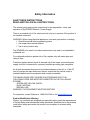
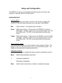
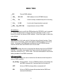
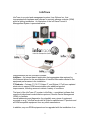
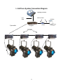
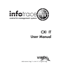
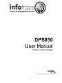
DPS850 User Manual Dimmer / Power Supply 1 CONTENTS Declaration of Conformity ……….……………………….3 Safety Information………………….………………………4 Introduction…………………………………………………5 Installation…………………………………………………..6 Setup and Configuration…………………………………..7 Menu tree……………………………………………………8 InfoTrace……………………………………………….……9 InfoTrace System Connection Diagram…………………11 RDM functionality………………………………………….12 Maintenance……………………………………………….13 Specifications…..………….………………………………14 Warranty Information………..………………………….…15 2 Declaration of Conformity Page 3 Safety Information SAVE THESE INSTRUCTIONS READ AND FOLLOW ALL INSTRUCTIONS This manual gives step-by-step instructions for the preparation, setup, and operation of the DPS850 Dimmer / Power Supply. There is a potential risk of fire, electric shock or injury to persons if the product is not used as instructed. WARNING: When using electrical appliances, use basic precautions, including: Read this manual before connecting power. Use supervision around children. Use in a dry location only. The DPsS850 to be used in an indoor environment only and is not intended for residential use. For continued protection against risk of fire, replace only with same type and rating of fuse. Protection against electric shock is assured only if the mains connected power supply cord set is connected to a properly earthed grounding type receptacle. An all pole disconnect device must be located adjacent to the unit or, if the AC cord is used as the main disconnect device, ensure that the socket-outlet is located/installed near the equipment and is easily accessible. THE MAINS LEADS ARE COLORED IN ACCORDANCE WITH THE FOLLOWING CODE AND MUST BE CONNECTED IN THE FOLLOWING SCHEME: - GREEN AND YELLOW: EARTH - BLUE: NEUTRAL - BROWN: LINE WARNING: THIS EQUIPMENT MUST BE EARTHED. For questions, contact Wybron at 1-800-624-0146 or visit www.wybron.com. Product Modification Warning Wybron, Inc. products are designed and manufactured to meet the requirements of United States and International safety standards. Modifications to the products could affect safety and render the product non-compliant to relevant safety standards. 4 Introduction The DPS850 is a combination dimmer / power supply allowing the user to create a stand alone fixture from a conventional lighting fixture and theatrical accessory. The DPS850 accepts 115 – 240VAC 50/60Hz input power and DMX and provides up to 800 watts of dimming for the fixture, as well as DC power and control signal for theatrical accessories including scrollers, gobo rotators, and dichroic color mixers. When used with the InfoTrace system the DPS850 also provides connectivity information allowing the user to abstract the separate components as a single device. 5 Installation NEXERA The DPS850 can be configured as an integral part of the Nexera fixture. In this configuration the DPS850 dimmed output is hard wired to the Nexera lamp assembly eliminating the lamp connection as a potential point of failure. The DPS850 can either be hung from pipe near the Nexera fixture or bolted to the Nexera yoke. Connect the DPS850 to a grounded power circuit 100 – 240VAC ~ 50/60Hz. Connect the four pin XLR accessory output to the Nexera color module Power/Signal input. The DPS850 provides power and passes DMX and RDM signals through to the color module. If used, connect DMX / RDM signal to the DPS850 five pin XLR connector labled “DMX IN”. DMX may be passed through the DPS850 to other devices by using the connector labeled “DMX OUT”. CONVENTIONAL LUMINAIRE The DPS850 may be configured to be used with any luminaire up to 800 watts. A female power connector can be installed on the dimmed output cord to match the connector used on the luminaire. The DPS850 can be mounted to the yoke of many theatrical fixtures or hung from mounting pipe near the associated fixture. Connect the DPS850 to a grounded power circuit 100 – 240VAC ~ 50/60Hz. Connect the four pin XLR accessory output to the Forerunner, CXI IT, ColoramIT, or other theatrical accessory in use with the fixture. Connect DMX / RDM signal to the DPS850 five pin XLR connector labeled “DMX IN”. DMX may be passed through the DPS850 to other devices by using the “DMX OUT” connector. 6 Setup and Configuration The DPS850 can be set up and configured locally using the four button user interface or remotely with the InfoGate system. USER INTERFACE Indicator LED’s Three LED indicators are located to the left of the accessory output XLR connector to provide instant information as to the state of the DPS850. Red Power indicator. On anytime power is present. Green DMX signal indicator. Flashes when the DPS850 is receiving a DMX signal. Indicator is active for one minute after power up or the last button press. The LED can be reactivated by pressing any button. Yellow RDM signal indicator. Flashes when the DPS850 is receiving RDM messages. Indicator is active for one minute after power up or the last button press. The LED can be reactivated by pressing any button. Seven segment display User menus are displayed on a three character seven segment display. The display is active for one minute after power up or the last button press. The display can be reactivated by pressing any button. Pushbutton interface Four buttons are used to navigate the menu and select configuration options. Menu Used to select between menu items. + Increment configuration. - Decrement configuration. Enter Used to enter a menu item or confirm a configuration change. 7 MENU TREE __001 Current DMX address _ _ _ Adr_ 001-512 DMX address for the DPS850 dimmer _ _ _ Foc_ On Used to locally command lamp on for focusing _ _ _ Loc_ 0-100 Local control lamp intensity in percent _ _ __LOS_ dLy, OFF, ON Lamp behavior at loss of DMX. Adr (Address) Use this menu item to modify the DMX address the DPS850 is set to respond to. Press the Enter button to choose this menu item then use the + and – buttons to modify the dimmer’s DMX address. Press Enter again to select the new address. Foc (Focus) This menu item is for local control of the lamp during fixture focusing. Press enter to turn on the lamp. Press enter again to take the dimmer out of focus mode. A change in the DMX level commanded on the DPS850 dimmer channel will also take the DPS850 out of focus mode. Loc (Local) Local control allows the user to command the dimmer level from the DPS850 interface. It provides more control than Focus mode by allowing the user to select the intensity on a 0 – 100% scale. The level commanded in local mode takes precedence over DMX commands. LOS (Loss of DMX) This menu item allows the user to decide how the dimmer should respond to a loss of DMX condition. dLy (Delay) Factory default. At loss of DMX the dimmer will maintain the last DMX command for 2 minutes then turn the lamp off. OFF At loss of DMX the lamp will be commanded off. ON At loss of DMX the lamp will maintain the last DMX level command indefinitely. 8 InfoTrace InfoTrace is a control and management system, from Wybron Inc., that incorporates both hardware and software to remotely manage a device (RDM) within a lighting installation. An illustration of the InfoTrace Control & Management System is presented below: Figure 1 The diagram above outlines the key components, which include: InfoTrace – The entire system is referred to as the InfoTrace System InfoGate – The software and hardware required to facilitate the transfer and display of information InfoChip – A conversion chip that can be used with non-RDM equipment to allow communication with the InfoGate Software InfoStore – An Internet base`d application that aggregates data captured by InfoGate and allows for the accumulation of historical information related to the equipment performance in the installation IT Products – Coloram IT, CXI IT, Eclipse IT, and Eclipse II IT all have updated electronics to support RDM communication plus additional product improvements, including sensors to detect a variety of conditions. The heart of the InfoTrace (IT) system is InfoGate — specialized software that uses the bi-directional communications protocol, Remote Device Management (RDM), to facilitate remote addressing and diagnostics for potentially every piece of equipment mounted on a rig. InfoGate works with all Wybron manufactured IT products and all RDM-compatible equipment from any other manufacturer. In addition, any non-RDM equipment can be upgraded with the installation of an 9 InfoChip. Because InfoGate can work with any equipment, the setup, unit testing, and troubleshooting for an entire rig can be coordinated from a single laptop. Wybron's IT equipment (Coloram IT, CXI IT, Eclipse IT, and Eclipse II IT) is equipped with a series of sensors that can relay a wealth of information to InfoGate. These sensors can detect everything from light, voltage, current, to fan speed and even gelstring frame color information. So while RDM equipment will allow identification and remote addressing, IT equipment can give more specific status information and warn of potential problems, possibly averting failures in the middle of a show. If the status of a device indicates any problem, InfoGate displays an alert with the nature of the problem and the exact location. Because of the designed intelligence contained within Wybron’s IT equipment, an additional level of robustness is present, thus significantly reducing the amount of troubleshooting and diagnostic time. InfoTrace provides the ability to: • Automate the setup of DMX addresses – no more manual setting of DIP switches • Proactively check the condition of equipment before, during and after a show • Track lamp duty cycles to predict lamp failures before they happen • Predict maintenance on equipment 10 3. InfoTrace System Connection Diagram Lighting console Ethernet cable 5 pin cable 5 pin cable Infogate DPS850 4 pin cable 11 Router InfoGate RDM FUNCTIONALITY The DPS850 is an ANSI E1.20 – 2006 RDM compliant device. When used with the InfoGate gateway and software it can be configured and monitored remotely. Besides the baseline RDM functionality such as discoverability, identify, and DMX start address, the DPS850 provides additional RDM functions. Personality The manner in which the DPS850 responds to a loss of DMX can be configured through an RDM system. The factory default personality will maintain the last DMX command for two minutes after loss of DMX then turn the lamp off. DPS850 personality can also be configured to stay on indefinitely or turn off immediately upon loss of DMX. User Text Fields The DPS850 provides two areas for the user to store text information. The device label is a text field allows the user to give a particular device a descriptive name up to 16 charecters such as ‘Unit 5’, or ‘Upstage Right’. The second area is the maintenance field where the user can store maintenance notes like ‘Changed fuse 8/14/07’ Status Reporting Many aspects about the state of the lamp connected to the dimmed output of the DPS850 are reported through RDM including: State of the lamp (On / Off) Lamp faults – blown or disconnected lamp Lamp electrical current Total lamp hours of operation Connected Devices The DPS850 will listen for RDM message traffic originating from the connected accessory output. If detected, it will report this information to the RDM controller to facilitate automatic associations between the dimmed lamp and its accessory. 12 Maintenance SOFTWARE UPDATES DPS850 firmware can be updated as new firmware versions become available through the DMX/RDM port using an InfoGate gateway and the InfoGate application. DPS850 firmware updates can be found at www.wybron.com Specific instructions for upgrading firmware in DPS850 and other Wybron equipment can be found in the InfoGate User Manual, Firmware Upgrades section. Equipment Compatibility DIMMED OUTPUT The DPS850 can operate with any incandescent lamp rated 100 – 240VAC, 800W or lower. ACCESSORY OUTPUT The DPS850 is compatible with Forerunner, Nexera LX, and Wybron IT equipment. DO NOT USE COLORAM II EQUIPMENT WITH THE DPS850 Pinout of the accessory output is as follows: Pin 1: Pin 2: Pin 3: Pin 4: Common Data Data + +24 VDC (50W max) 13 Specifications PHYSICAL Length: Width: Height: Weight: Input cord length: Output cord length: 7.750” (197mm) 5.950” (151mm) 3.875” (98mm) 3.9 lbs. (1.77kg) 36” (914mm) 36” (914mm) ELECTRICAL (Dimmer) Number of dimmers: Input voltage: Minimum dimmer load: Maximum dimmer load: Rise time: Circuit protection: 1 100-240VAC ~50/60Hz 0W 800W 700_S Magnetic circuit breaker 10A ELECTRICAL (Power supply) Maximum load: Circuit protection: 35W Fuse 250V/3A rating ENVIRONMENTAL Ambient temperature: Relative humidity: Cooling: 0 - 40˚C Maximum 95% non-condensing Convection 14 Warranty Information WYBRON, INC. warrants to the original owner or retail customer that for a period of one year from date of delivery of a portable system or energization of a permanently installed system (up to a maximum of 18 months from delivery) its products will be free from defects in materials and workmanship under normal use and service. Warranty does not cover any product or part of a product subject to accident, negligence, alteration, abuse, misuse or any accessories or parts not supplied by WYBRON, INC. Warranty does not cover "consumable" parts such as fuses, lamps, or color media. WYBRON, INC.'s warranty does not extend to items not manufactured by us. Freight terms on warranty repairs are FOB WYBRON, INC. factory or designated repair facility. Collect shipments or freight allowances will not be accepted. WYBRON, INC.'s sole responsibility under this warranty shall be to repair or replace at WYBRON, INC.'s option such parts as shall be determined to be defected on WYBRON, INC.'s inspection. WYBRON, INC. will not assume any responsibility for any labor expended or materials used to repair any equipment without WYBRON, INC.'s prior written authorization. WYBRON, INC. shall not be responsible for any incidental, general or consequential damages to property, damages for loss of use, time, profits or income, or any other charges. The owner's obligations during the warranty period under this warranty are to notify WYBRON, INC. at WYBRON, INC.'s address within one week of any suspected defect, and return the goods prepaid to WYBRON, INC. at their factory or authorized service center. This warranty is contingent on the customer's full and timely compliance with the terms of payment set forth in said purchase order. This warranty is expressly in lieu of any and all other warranties expressed or implied including the warranties of merchantability and fitness for a particular purpose and of other obligations and liabilities on our part. The owner acknowledges that no other representations were made to him or relied upon him with respect to the quality and function of the goods sold. This written warranty is intended as a complete and exclusive statement of the terms thereof. Prior dealings or trade usage shall not be relevant to modify, explain or vary this warranty. Acceptance of, or acquiescing in, a course of performance under this warranty shall not modify the meaning of this agreement even though either party has knowledge of the performance and a chance to object. WYBRON, INC. - TEL 719-548-9774 - FAX 719-548-0432 Email: [email protected] - Visit us on the World Wide Web at http://www.wybron.com 15