1
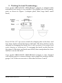
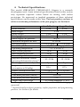
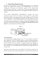
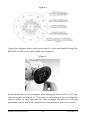
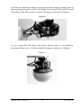
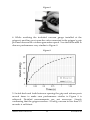
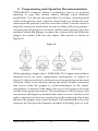
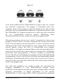
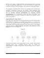
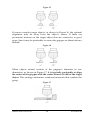
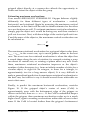
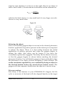
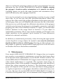
Model #RB3-065/035
Product Manual
©Empire Robotics, Inc.
R20140519
Table of Contents
1.
Overview ........................................................................................ 1
2.
Safety Information ......................................................................... 2
3.
Packing List and Terminology..................................................... 4
4.
Technical Specifications ................................................................ 5
5.
Operating Requirements .............................................................. 6
6.
Installation ...................................................................................... 9
7.
Performance Confirmation & Diagnosis .................................. 12
8.
Programming and Operation Recommendations ................... 15
9.
Maintenance ................................................................................. 24
10. Troubleshooting .......................................................................... 25
11. Technical Support........................................................................ 25
12. Warranty ....................................................................................... 26
13. Notes ............................................................................................. 27
1. Overview
Thank you for purchasing a VERSABALL® Gripper from Empire
Robotics. VERSABALL® utilizes Empire’s proprietary granular
jamming technology to achieve flexible and adaptive gripping
through rapid hardness modulation. For video demonstrations of the
gripping abilities of this technology visit www.empirerobotics.com.
This product manual contains important safety, installation, and
usage information to help you get the most out of your VERSABALL®
Gripper. Because your VERSABALL® represents a unique new
technology, we highly recommend reading this manual thoroughly.
If you have additional questions not covered by this document or if
you need additional help setting up or operating your gripper, contact
our technical support at [email protected].
At Empire Robotics we continually strive to deliver quality products
for the industrial automation market. Your feedback is appreciated
and may be provided at [email protected]. Thank you for
choosing Empire Robotics!
Model #RB3-065/035
1
R20140519
2. Safety Information
This model #RB3-065/035 VERSABALL® Gripper is a research
development unit, and therefore has no expressed or implied safety
guarantee. Specific safety risks may include but are not limited to the
following:
General hazards:
A. Your model #RB3-065/035 VERSABALL® Gripper contains rigid
aluminum components. The green spherical head of the gripper
also becomes very hard when its vacuum-jammed state is
induced. The gripper is therefore capable of causing significant
bodily harm if it strikes a person (e.g. when in use on a fastmoving robot arm). It is recommended to operate the gripper only
after performing an appropriate risk assessment.
B. Your model #RB3-065/035 VERSABALL® Gripper is not rated for
food handling operations. We therefore do not recommend using
this gripper for handling any food items.
C. Your model #RB3-065/035 VERSABALL® Gripper should be
treated as a piece of industrial equipment. Because of the variety
of potential safety hazards described here, we do not recommend
that children use this device.
Balloon membrane hazards:
D. Your model #RB3-065/035 VERSABALL® Gripper contains
mechanisms to help prevent overinflation and the possibility of
subsequent burst. However, as described in Section 6, you have
the ability to override the overinflate protection if needed
depending on your application. Exercise additional caution
whenever you override the overinflation protection.
E. The outer balloon membrane of your model #RB3-065/035
VERSABALL® Gripper consists of a proprietary blend of
elastomeric materials and may contain natural rubber latex. Those
with latex allergies should avoid direct skin contact with the
balloon membrane.
Model #RB3-065/035
2
R20140519
Granular material hazards:
F. Your model #RB3-065/035 VERSABALL® Gripper contains
redundant filtering mechanisms to prevent dust particles from
entering the atmosphere. In normal use, the model #RB3-065/035
VERSABALL® Gripper emits trace amounts of dust into the
atmosphere. These levels have been measured to be well below
the OSHA recommended limits for respirable dust and nuisance
dust, as documented in the material’s MSDS.
If your gripper overinflates, violently collides with a sharp object,
is used beyond its intended service life, or experiences some other
unforeseen failure, the granular material contained within the
gripper could be released into the environment. The grains are
non-toxic and can be cleaned up with a dustpan or vacuum
cleaner. During such a failure, some nuisance airborne dust may
also be released, which in turn could lead to the unlikely but
possible event of mechanical lung irritation (silicosis). Dampening
the granular material with water spray will reduce the risk of lung
irritation during cleanup. Similarly, if grains somehow reach your
eyes, they could potentially cause mechanical eye irritation. It is
advised to wear safety glasses if you are working in very close
proximity to the gripper – especially if you choose to override
your overinflate protection. If eye irritation occurs, gently rinse
your eyes with water.
Model #RB3-065/035
3
R20140519
3. Packing List and Terminology
Your model #RB3-065/035 VERSABALL® gripper is shipped fully
assembled and ready to be installed. The gripper has four primary
parts as shown in Figure 1 (adapter plate, base, large head, small
head).
Figure 1
Four #10-24 x 1/2" cap screws attach the adapter plate to the base, and
four draw latches attach the base to the head. The draw latches can be
released to disengage the head (this is only necessary if the gripper head
needs changing or replacement). To reengage the head, ensure that the
flat plates of the base and head meet flush, then manipulate the draw
latches to secure the head.
Your model #RB3-065/035 VERSABALL® Gripper is also shipped
with tubing, push-to-connect fittings, and a diagnostic analog vacuum
gauge. Use of these accessories is described Sections 5 and 6.
Model #RB3-065/035
4
R20140519
4. Technical Specifications
This model #RB3-065/035 VERSABALL® Gripper is a research
development unit. Some technical specifications listed in this section
only represent expected values based on testing with earlier
prototypes. No expressed or implied guarantee of these technical
specifications can be made at this time. For best practices on how to
achieve maximum performance with your gripper, see Section 8.
Small Head
Large Head
Head diameter
3.5 in
6.5 in
Base weight
2.1 lb
Head weight
1.4 lb
5.5 lb
Total gripper size
5.0 x 5.0 x 4.5 in 6.5 x 6.5 x 7.5 in
Rated supply air pressure
80 psi
Minimum required air flow*
23 SCFM
Air use per grip
~ 0.02 ft3/grip
~ 0.1 ft3/grip
Head life cycle**
20,000 – 60,000 grips
Operating temperature
~ 33° F to 160° F
Max vertical payload**
~ 10 lb
~ 20 lb
Max tangential payload
~ 20 lb
~ 40 lb
Retention (pull-out) force**
~ 0 – 10 lb
~ 0 – 20 lb
Required minimum contact
~ 10 – 15 lb
~ 15 – 20 lb
(pressing/deformation) force**
Pinching pressure on object**
~ 5 psi
~ 7 psi
Grip time
0.1 s
0.7 s
(evacuation to 20 inHg)
Sealed vacuum hold time
< 0.5 inHg loss per 30 seconds
Grip release time
~ 0.15 s
~1s
Placement precision (linear)
~ ± 0.03 in
Placement precision (angular)
~ ± 2°
Target object size range
~ 50% head diameter +/- 20%
* with supply hose open to atmosphere (about 7.1 SCFM with gripper
connected)
** depends heavily on object geometry, surface properties, and programming
practices. See Section 8 for details.
Model #RB3-065/035
5
R20140519
5. Operating Requirements
The most critical aspect of the installation process is air. Without
proper air supply and valving, your VERSABALL® can still be
configured to function, but operation speeds will be significantly
reduced and you’ll have to contact our customer support for some
help optimizing the performance of the gripper with the available air
supply.
Your model #RB3-065/035 VERSABALL® Gripper has three
pneumatic ports as shown in Figure 2, and requires two pressurized
air inputs. When your gripper arrives, the auxiliary port will come
with a diagnostic vacuum gauge installed, and the release port will
come with a flow control valve installed. Note: supplying pressurized
air at the grip port generates a vacuum within the gripper. Do not
supply a vacuum line at this port; the gripper accepts pressurized air
only. We recommend the following setup:
Figure 2
At the grip port:
We recommend installing tubing with 1/2" outer diameter and 5/16”
inner diameter. The 1/2" diameter push-to-connect fitting installed at
the grip port is rated for polyurethane tubing (with a hardness of
Shore A 88-97) and nylon tubing. A length of appropriate tubing has
been included in your shipment, and McMaster-Carr p/n 5648K33 is
also suitable. We recommend that the length of this tubing should not
exceed 10 ft.
Upstream of the grip port, some method of valving is required. An
electric solenoid valve rated for high flow rates and with a minimum
Model #RB3-065/035
6
R20140519
port size of 3/8" NPT is recommended. Empire Robotics uses Clippard
p/n MME-33WES for internal testing. Best practices for timing the
opening and closing of the valves are provided in Section 8.
At the release port:
We recommend installing tubing with 1/4" outer diameter and 3/16"
inner diameter. Other configurations are not recommended; larger
diameters may result in rupture of the gripper and smaller diameters
adversely affect the inflation speed of the gripper. The 1/4" diameter
push-to-connect fitting installed at the release port’s flow control
valve is rated for polyurethane (with a hardness of Shore A 88-97) and
nylon tubing. A length of appropriate tubing has been included in
your shipment, and McMaster-Carr p/n 5648K25 is also suitable. We
recommend that the length of this tubing should not exceed 10 ft.
Upstream of the release port, some method of valving is required for
this hose as well. An electric solenoid valve with a minimum port size
of 1/4" NPT is recommended for the release port. Empire Robotics
uses Clippard p/n MME-32QES for internal testing. Best practices for
timing the opening and closing of the valves are given in Section 8.
Upstream air supply requirements:
For optimal performance, a pressure of 80 psi should be supplied. The
pressure must not exceed 90 psi. All pneumatic components
(couplings, fittings, regulators, electric valves, etc.) should be rated for
flow rates well in excess of 25 SCFM. All piping and tubing should
have an outer diameter of at least 1/2" and an internal diameter of at
least 3/8". Large distances or numbers of pneumatic components
increase the resistance to flow in an additive manner. Therefore, when
long distances or large number of components exist upstream,
components rated for higher flow rates as well as larger tubing and
pipe diameters may be required.
Moisture and other contaminates in the air lines can negatively
influence the performance of your gripper, so filtering and
dehumidifying your air supply is recommended. We recommend
Model #RB3-065/035
7
R20140519
Clippard p/n MMF-4W-F5 if you have no other filtering or moisture
separation equipment in place.
Testing your air supply:
Test your air supply to ensure proper pressure and flow rate are
available for the gripper. Simply checking the rating on your
compressor is often insufficient due to restrictions, distance, and other
losses as mentioned previously. Utilizing a pressure gauge and flow
meter is recommended.
At the point of entry into the grip port (through the 1/2" diameter
tubing immediately prior to entry into the device), your air supply
should be capable of providing 80 psi with a flow rate of 23 SCFM.
Measure these when the hose is disconnected from the gripper. When
the hose is connected to the gripper and air is flowing, this should
correspond to a flow rate of approximately 7.1 SCFM.
These air requirements may sound somewhat complicated, but most
shop air supplies will already meet all these requirements at the
nearest pipe. Supplying your gripper with adequate airflow is then
simply a matter of ensuring that appropriate fittings and tubing are
used between the pipe and the gripper. Again, if you are unable to
provide proper air supply and valving your VERSABALL® Gripper
can still be configured to function, but operation speeds will be
significantly reduced and you’ll have to contact our customer support
for some help optimizing the performance of the gripper with the
available air supply.
Model #RB3-065/035
8
R20140519
6. Installation
Make sure that your robot is powered down and in a safe position before
installing your gripper. Also turn off the air supply at an upstream shut-off
valve during installation.
Your model #RB3-065/035 VERSABALL® Gripper comes with an
adapter plate and mounting screws in order to easily interface with a
variety of industrial robot arms. During shipping the adapter plate is
attached to the gripper. To begin installation, first remove the adapter
plate from base of the gripper by removing the four radially located
#10-24 x 1/2" cap screws as shown in Figure 3.
Figure 3
Next, determine which set of holes in the adapter plate matches the
bolt pattern on your robot arm (generally 4 mounting screws will be
needed). A drawing of the bolt patterns provided on the gripper’s
adapter plate is shown in Figure 4.
Model #RB3-065/035
9
R20140519
Figure 4
Align the adapter plate with your robot’s wrist and install using the
M4, M5, or M6 screws provided (see Figure 5).
Figure 5
Reattach the base to the adapter plate using the four #10-24 x 1/2" cap
screws (again see Figure 3). This step is a bit easier if you can flip the
robot’s wrist to face upward. Be sure to align the base so that the
pneumatic ports are well situated for connection to your air source.
Model #RB3-065/035
10
R20140519
Cut the provided air tubing to an appropriate length, making sure to
leave enough length to allow full range of motion of the robot. Install
the tubing with the push-to-connect fittings as shown in Figure 6.
Figure 6
If you separated the base and head pieces prior to installation,
reconnect them now. A fully installed gripper is shown in Figure 7.
Figure 7
Model #RB3-065/035
11
R20140519
7. Performance Confirmation & Diagnosis
Your model #RB3-065/035 VERSABALL® Gripper comes with a
diagnostic vacuum gauge installed at the auxiliary port. We
recommend the following procedure to confirm your gripper’s
performance immediately following installation. We recommend
using the large head for this test. Repeat the process below whenever
you change to a different head size. However, repeating this process
is not necessary when simply replacing a worn head with a newer
head of the same size.
1. The flow-control valve installed at your gripper’s release port is
shipped fully closed. Check that the valve is closed by turning
clockwise as shown in Figure 8.
2. Next, open the upstream solenoid valve connected to the gripper’s
release port, making sure you are able to close this valve again
quickly. No air should flow because the flow-control valve is fully
closed.
3. With the pressure on, slowly open the flow-control valve by turning
counter-clockwise so that air can begin flowing into the gripper.
Mechanisms within the gripper will limit the expansion of the balloon
head and prevent overinflation. Continue opening the flow-control
valve until the gripper’s balloon head reaches a steady-state
enlargement of about 10%. Use the black locking-nut to lock the flowcontrol valve in this position, turn off the positive pressure, and
continue to the next step.
Model #RB3-065/035
12
R20140519
Figure 8
4. While watching the included vacuum gauge installed at the
gripper’s auxiliary port, open the valve connected to the gripper’s grip
port and observe the vacuum generation speed. You should be able to
observe performance very similar to Figure 9.
Figure 9
5. Switch back and forth between opening the grip and release ports
several times to make sure performance similar to Figure 9 is
achieved. Detailed measurements are not necessary. Simply
confirming that the gripper reaches ~25 inHg vacuum in less than 1.5
seconds is sufficient.
Model #RB3-065/035
13
R20140519
If the ultimate vacuum level does not reach at least 22 inHg, either the
upstream air supply is restricted or there is a problem with the device.
The included vacuum gauge is only capable of ±3 inHg accuracy,
which is sufficient for simple install verification.
6. Adjusting the flow-control valve on the release port will require
some tuning. A tradeoff exists between inflation (object
release/ejection) speed and overinflation protection. With the valve
fully open, you can override your overinflate protection to achieve the
fastest ejection speeds. This is a perfectly fine way to use your gripper,
but comes with obvious additional risk.
Model #RB3-065/035
14
R20140519
8. Programming and Operation Recommendations
VERSABALL® Grippers utilize a technology known as granular
jamming to grip and release objects through rapid hardness
modulation. You can see this same effect if you buy vacuum-packed
coffee at the grocery store – hard as a brick until you release the seal,
whereupon the particles will flow more like a fluid. It can be useful to
keep this concept in mind when you are working with your gripper –
vacuum-pack the gripper to so that it will become rigid and grip onto
an object, inflate the gripper to release the vacuum seal and soften the
gripper for contact with the next object. This process is shown in
Figure 10.
Figure 10
When gripping a target object, VERSABALL® Grippers may achieve
retention forces by three independent mechanisms, as shown in
Figure 11. Shown on the left, friction forces from pinching are the most
common. These forces develop during the small volume contraction
that occurs when the gripper is vacuum-hardened. In the center,
entrapment or capture of the object can occur if the gripper can wrap
around some geometric feature. This mechanism is less common, but
can increase holding force dramatically when it occurs. Finally on the
right, a vacuum-suction force can develop in the sealed gap that forms
between the gripper and a smooth object. This mechanism is also less
common, but can provide dramatic increases in holding force as well.
Model #RB3-065/035
15
R20140519
Figure 11
Your model #RB3-065/035 VERSABALL® Gripper does not contain
any electrical components. The gripper is controlled with usersupplied valves at the gripper’s grip and release ports. This section
proceeds with recommendations based on a typical installation (with
the VERSABALL® Gripper mounted on a robot arm and controlled
by two independent solenoid valves). Modifying these
recommendations for other setups should be straightforward.
When programming, always use a “pulse” command to activate your
gripper’s control valves. A pulse command will return even in the
event of an emergency-stop (as opposed to a “wait” command, which
will hang in the event of an emergency stop). Using pulse commands
should greatly reduce the risk of overinflating your gripper.
Nevertheless, we highly recommend that you do not open the positive
pressure flow-control valve far enough to override your overinflation
protection until programming is mostly complete (or preferably
never). The risk of overinflating your gripper is especially high during
programming. In the event that you do make a programming mistake
and begin overinflating the head, a quick way to rescue it is to first estop your robot arm, and then release the draw latches that attach the
head to the gripper base.
The following guidelines are meant to help you maximize the
gripping capabilities of your VERSABALL® Gripper. These
guidelines can be applied toward many types of target objects, though
gripping performance is highly dependent on the specific
characteristics of each target object. These characteristics primarily
Model #RB3-065/035
16
R20140519
include: size, shape, weight, hardness, and surface texture. In general
though, the gripping capabilities of your VERSABALL® Gripper will
correlate with how well the gripper can conform to the target object.
The gripper’s versatility does allow it to operate well outside these
optimum guidelines, however the farther from optimum any
operation is, the less predictable the performance will be. Be careful
not to sacrifice optimal performance by forgoing careful
programming. It is worthwhile to take the time to program your
gripping routine a bit more carefully in order to get optimal results
from your gripper.
Approaching the target object:
If possible, the target object should be presented on a flat rigid surface.
VERSABALL® Grippers can reliably grip objects of varying size,
however the optimal width of the target object (or the feature on the
target object that the gripper interfaces with) that results in the largest
payload capacity is approximately one half of the diameter of the
gripper, as shown in Figure 12.
Figure 12
Note that the height of the target object is also crucial; taller objects
typically have more available surface area on which the
VERSABALL® Gripper can generate side-pinching forces, as shown
in Figure 13.
Model #RB3-065/035
17
R20140519
Figure 13
Approach the target object from above as shown in Figure 14. The
gripper should be oriented vertically downward (so the logos and
labels read horizontal left-to right). Whenever possible, approach in
the direction perpendicular to the work surface. Not only does this
prevent unintentional movement of the target object, but it also
minimizes the force required to deform the gripper.
Figure 14
Greater retention forces are generally achieved when the target
object is aligned with the gripper’s central axis, as shown in Figure
15. Careful alignment enables more symmetrical generation of grip
forces, which typically translates to higher retention forces.
Model #RB3-065/035
18
R20140519
Figure 15
For more complex target objects, as shown in Figure 16, the optimal
alignment may be away from the object’s center. If there are
prominent features on the target object that are conducive to good
grips, then it may be preferable to center the gripper on these features
instead.
Figure 16
When objects extend outside of the gripper’s diameter in one
dimension, as shown in Figure 17, it is typically preferable to align
the center of the gripper with the center of mass (CoM) of the target
object. This strategy minimizes rotational moments that weaken the
grasp.
Figure 17
Model #RB3-065/035
19
R20140519
Conforming to the target object:
When the gripper is on approach about 3” above the target object,
begin applying positive pressure in order to soften the gripper (i.e.
open the valve connected to the gripper’s release port). The pulse
should last approximately 1 second and can occur while the gripper
is moving. You may find that it is advantageous to continue applying
positive pressure as the gripper is pressed onto the target object to aid
in gripper deformation. When ideally utilized, positive pressure will
serve to minimize the required contact force between the gripper
and the object, but will also leave little or no excess air in the gripper
when contact is complete. Too much air left within the gripper after
contact can dramatically weaken the grip force because vacuumhardening will cause the gripper to contract away from the object and
towards this void space, instead of in the desired pinching direction.
Experimenting with this positive pressure timing (as well as the
included flow-control valve on the release port) will help you tune the
gripper’s performance to best match your target object.
Press the gripper onto the target object from above. If force control is
available, it is recommended to contact (press onto) the object with
approximately 10-20 lbf. This contact will also require some tuning,
especially if force feedback is not available.
For most target objects, the deeper the object can be driven up into
the gripper, the greater the resulting gripping force. However, if the
gripper is pushed down too far such that it contacts the work surface,
gripping force can begin to decrease, as shown in Figure 18. This is
because the frictional forces between the gripper and the work surface
can prevent the gripper from contracting to conform to the target
object.
Model #RB3-065/035
20
R20140519
Figure 18
When choosing the appropriate contact depth for a target object, be
careful to use only the minimum depth needed to achieve reliable
grips. Driving an object deeper into the gripper to generate
unnecessarily high grip forces will serve to decrease the life of the
balloon membrane.
Vacuum-hardening to grip the object:
After contact and deformation of the gripper is complete, vacuumharden the gripper (open the valve connected to the gripper’s grip
port). Longer evacuation times make the gripper harder and result
in better grips, however some objects can be gripped without full
hardening. In general, a minimum of 15 inHg vacuum is required to
grip easier objects, with 20 inHg or even 25 inHg being preferable for
more difficult objects. Figure 9 will help you estimate what grip time
you may need, and achieving a minimum grip time for your target
object will require some tuning. In some applications it is also possible
to begin evacuating the gripper before or during contact with the
object so that grip times as short as zero-seconds may be achieved.
Once the gripper is vacuum-hardened, you may close the valve
connected to the grip port; the gripper will automatically seal to
maintain its vacuum level.
Your model #RB3-065/035 VERSABALL® Gripper does not contain
any sensors. If grip confirmation is required, we recommend using
computer vision to sense whether the object has been picked up –
either by the object’s absence from its previous location, or by pointing
the gripped object directly at the camera with the gripper. Pointing a
Model #RB3-065/035
21
R20140519
gripped object directly at a camera also affords the opportunity to
locate and orient the object within the grasp.
Estimating maximum accelerations:
Your model #RB3-065/035 VERSABALL® Gripper behaves slightly
differently for three different types of acceleration – vertical,
horizontal, and rotational. Begin by assessing the maximum vertical
acceleration, as this limit will be used to obtain estimates for the other
two accelerations as well. To estimate maximum vertical acceleration,
simply grip the object as it would be during use, and then conduct a
pull-out force test. Next, with knowledge of the vertical pull-out force
F and the mass of the object m, the maximum vertical acceleration can
be calculated as:
amax,v =
F
m
The maximum rotational acceleration for a gripped object scales from
amax,r ≈ amax,v in the worst case, up to much greater values in the best
case. The worst case for rotational acceleration is when the object has
a round shape along the axis of rotation, for example rotating a soup
can about its central axis, or rotating a sphere about any axis. From
there, maximum rotational acceleration improves as the object’s
number of sides decreases (e.g. from an infinite number of sides for a
circular object, to eight for an octagon, to three for a triangle, to
approximately two for a long narrow object). It is very difficult to
make a generalized prediction for maximum rotational acceleration in
the best case, but suffice to say it should exceed those achievable on
most robot arms.
Finally, to predict the maximum horizontal acceleration, consider
Figure 19. If the gripped object’s center of mass (CoM) is
approximately even with the bottommost edge of the gripper as
shown on the left, then amax,h ≈ amax,v . If the CoM is embedded deeper
within the gripper, then maximum acceleration scales up to a much
higher level, again exceeding accelerations achievable on most robot
arms. If the CoM is located further than the gripper’s bottommost
Model #RB3-065/035
22
R20140519
edge by some distance d as shown on the right, then for an object of
mass m and width w, the maximum acceleration can be estimated as:
amax,h ≈
wamax,v
2d
which in the limit where w is very small and d is very large, can scale
down to a very small value.
Figure 19
Releasing the object:
Once a successfully gripped object is moved to the desired placement
location, application of positive pressure at the release port is required
to release the object. There is a short delay between the initial
application of positive pressure and when the gripper begins to
release the object (this delay can be longer if you have the
overinflation protection engaged). The delay can be timed, however,
so that the gripper begins its release before reaching the desired
placement location. You will find the gripper is least predictable when
the placement of an object involves dropping it some distance. To
ensure maximum repeatability, we recommend placing an object in
the desired location before any actual release motion occurs. The
gripper will then separate cleanly from the object as it moves away.
Wear prevention:
Like many of the features of your VERSABALL® Gripper, the life
cycle or wear-rate of the head will also depend heavily on the target
Model #RB3-065/035
23
R20140519
object as well as the gripping routine you have programmed. You can
maximize the life of your VERSABALL® heads by slightly varying
the gripper’s location and/or orientation as it contacts an object.
Gripping objects in exactly the same location and orientation every
time will adversely affect gripper head life.
Let’s say for example you are programming a routine to grip a small
steel cube. If you use just one pick position/orientation, where the
edges of the cube contact the gripper membrane in the same exact spot
on each grip, then you will dramatically decrease the life of the head.
If however you cycle through five different orientations of the gripper
(which is easy because the gripper is rotationally symmetric), each still
gripping the cube at the center but rotated 72° apart, you should then
achieve lifetimes in the range listed in Section 4. If your object is
rotationally symmetric, like a soup can for example, you’ll need to use
slight variations in the gripper’s pick location (2-3 mm difference)
instead of rotational variations.
In addition, as mentioned previously, when choosing the appropriate
contact depth for a target object, be careful to use only the minimum
depth needed to achieve reliable grips. Driving an object deeper into
the gripper to generate unnecessarily high grip forces will also serve
to decrease the life of the balloon membrane.
9. Maintenance
Your model #RB3-065/035 VERSABALL® Gripper does not require
any regular or preventative maintenance except for brief inspections
by an operator and replacements of worn heads. Without sensors, the
model #RB3-065/035 VERSABALL® Gripper cannot alert the operator
when head replacement is required. The operator must keep an
approximate count of the number of attempted grips, and should not
exceed the values reported in Section 4. The maximum number of
grips will depend on the specific use-case and objects being gripped,
so regular inspections of the gripper should be conducted in any new
use-case. Because the model #RB3-065/035 VERSABALL® Gripper is
a research development unit, we recommend a brief inspection by an
Model #RB3-065/035
24
R20140519
operator during continuous use (approximately every 5,000 grips).
During this inspection, the operator should check for signs of wear or
damage on the gripper and that it is still functioning properly.
Especially if the gripper is operating in a dusty environment, an
occasional wipe-down with a damp cloth is recommend.
10. Troubleshooting
Because the model #RB3-065/035 VERSABALL® Gripper is a new
technology, some troubleshooting may be expected for first-time
users. If there are any problems you are unable to solve using the
information contained in this manual, please contact technical
support. Again, if you are unable to provide the recommended air
supply, we can help you modify your gripper to run using less air,
however grip speed will be greatly reduced and you may have to send
your gripper back to enable this modification. Please contact technical
support for details.
11. Technical Support
If you have additional questions not covered by this document or if
you need additional help setting up or operating your gripper, contact
our technical support at [email protected]. Include your
name, contact information, and an optional description of the problem
or question you have. Yes, we know you’d probably prefer to have a
phone number to call, but our experience indicates we can provide
even faster service if you start by sending a very brief email. Trust us
– you can expect a very fast response call from us.
Model #RB3-065/035
25
R20140519
12. Warranty
As a customer, you are our number one priority, and we pride
ourselves on providing you with excellent service and an excellent
warranty program. Our approach is simple: (x) if there’s a problem in
the design or workmanship in your VERSABALL® Gripper, or (y) if
your VERSABALL® Gripper fails when used for the tasks it’s
designed for in accordance with the product manual provided along
with it, we'll fix it or replace it in order to solve the problem as quickly
as possible. Please let us know if you are not 100% happy with your
VERSABALL® Gripper. If you are unsatisfied with the performance
of your gripper, we'll refund your purchase in full. Contact
[email protected], and we’ll make sure your
VERSABALL® Gripper works for you.
Model #RB3-065/035
26
R20140519
13. Notes
Model #RB3-065/035
27
R20140519
Model #RB3-065/035
28
R20140519
Model #RB3-065/035
29
R20140519
Model #RB3-065/035
30
R20140519