1
APPLICATION NOTE
RX600 Series
CAN Application Programming Interface
R01AN0339EU0203
Rev. 2.03
Mar 23, 2013
Introduction
This application note introduces the Renesas CAN Application Programming Interface and explains how to use it to
send, receive, and monitor data on the CAN bus. It also explains briefly some features of the CAN peripheral.
Bundled with this application note comes the CAN API driver source code files config_r_can_rapi.h, r_can_api.h, and
r_can_api.c. Note that there are alternative ways to write the driver functions. For example you may want to write your
own driver functions to tailor a specific behavior.
The RX CAN peripheral has 32 CAN mailboxes to read from and write to in order to communicate over CAN. These
mailboxes are message ‘buffers’ and will hold the CAN data frame until it is overwritten by another incoming frame, or
rewritten by the application. Each mailbox can be configured dynamically to transmit or receive. Usually, most are
configured to receive and a few to transmit.
A CAN API is also available from Renesas for the CAN equipped MCUs in the families R32C, M32C, M16C, R8C, for
SH RCAN-ET MCUs SH7286, SH7137, and for the SH7216. Most, if not all, CAN MCUs are available on Renesas
Starter Kit boards. Demonstration source code for the API is available for all these devices and runs the same demo
across all of these devices so that they can be connected and run together.
The term ‘mailbox’, or in some literature ‘message box’ or ‘message buffer’ refers to the physical location where
messages are stored inside the MCU’s CAN peripheral. In this document we will use the term ‘mailbox’.
Target Device
RX600 Series of MCUs with CAN.
R01AN0339EU0203 Rev. 2.03
Mar 23, 2013
Page 1 of 29
RX600 Series
CAN Application Programming Interface
Contents
1.
CAN Basics ....................................................................................................................................... 3
2.
The CAN Peripheral .......................................................................................................................... 3
3.
Communication Layers ..................................................................................................................... 4
4.
The Mailbox ....................................................................................................................................... 4
5.
Using Extended ID ............................................................................................................................ 4
6.
Adding the CAN API to Your Project ................................................................................................. 5
7.
The CAN Config File ......................................................................................................................... 5
8.
The CAN API ..................................................................................................................................... 6
9.
CAN Interrupt Checklist ................................................................................................................... 25
10. Test Modes...................................................................................................................................... 25
11. Time Stamp ..................................................................................................................................... 28
12. CAN Sleep Mode............................................................................................................................. 28
13. CAN FIFO........................................................................................................................................ 28
Website and Support ............................................................................................................................... 29
Revision Record ...................................................................................................................................... 30
General Precautions in the Handling of MPU/MCU Products ................................................................. 31
R01AN0339EU0203 Rev. 2.03
Mar 23, 2013
Page 2 of 29
RX600 Series
1.
CAN Application Programming Interface
CAN Basics
CAN was designed to provide reliable, error-free network communication for applications in which safety and real-time
operation cannot be compromised. Its main attributes can be summarized as follows:
•
High reliability and noise immunity
•
Fewer connections
•
Flexible architecture
•
Error handling through peripherals
•
Low wiring cost
•
Scalability
The MCU and bus connectors need only two pins. Therefore, a CAN network is more reliable than other networking
schemes that need more wires and connections. Adding new nodes is simple; just tap the bus wire at any point.
CAN is based on a “multiple master, multiple slave” topology. Message or Data Frames transmitted do not contain the
addresses of either the transmitting node or of any intended receiving node. This means that any node can act as master
or slave at any time. Messages can be broadcast, or sent between nodes depending on which nodes at a particular
moment are listening to a certain ID. New nodes can be added without having to update others. Such design flexibility
makes it practical for building intelligent, redundant, and easily reconfigured systems.
Bit rate determines the number of nodes that can be connected and cable length. Allowed CAN data bit rates are: 62.5,
125, 250, 500 Kbps and 1 Mbps. At the highest speed, the network can support 30 nodes on a 40-meter cable. At lower
speeds, the network can support more than 100 nodes on a 1000-meter cable.
The basic building blocks of a CAN network are a CAN microcontroller, the firmware to run it, a CAN transceiver to
drive and read the bus signal, and a physical bus media (2 wires). Choose a CAN MCUs with enough mailboxes to fit
your applications.
2.
The CAN Peripheral
The Protocol Controller of the CAN peripheral in your CAN MCU must via the CAN Tx and Rx MCU pins be
connected to a bus transceiver located outside the chip. The Protocol Controller reads and writes to the peripheral
mailboxes depending on how they are configured. The configuration is done through the CAN Special Function
Registers described in your MCU’s HW manual. As the registers in the CAN peripheral must be configured and read in
the proper sequence to achieve useful communication, a CAN API greatly simplifies this – the API takes numerous
tedious issues and does them for you.
After initializing the peripheral, all you need to do is use the receive and transmit API calls, and on a regular basis
check for any CAN error states. If an error state is encountered the application can just wait and monitor for the
peripheral to recover, as the CAN peripheral takes itself on or off line depending on its state. After a recovery is
discovered, the application should restart.
R01AN0339EU0203 Rev. 2.03
Mar 23, 2013
Page 3 of 29
RX600 Series
3.
CAN Application Programming Interface
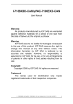
Communication Layers
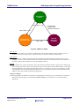
The figure below shows the CAN communication layers, with the application layer at the top and the hardware layer at
the bottom.
Figure 1. CAN physical and source code layers.
In this document we will not discuss any higher level protocols such as CANopen or DeviceNet. (For some Renesas
CAN MCUs there is a CANopen solution. Contact your sales representative.)
4.
The Mailbox
When a CAN message is to be sent, it must first be written to a mailbox by the application firmware. It will then be sent
automatically as soon as the bus becomes idle, unless a message of lower ID is sent by another node. If a mailbox is
configured to receive, the message is written to the mailbox by the Protocol Controller and must be copied by the user,
using the API, to user memory area quickly to free the mailbox for the next message coming from the network.
The API calls will do all the writing to and from the mailbox for you. All you have to do is provide application data
frame structures which the API functions can write incoming messages to and copy outgoing messages from. It is
recommended to have a least one structure for outgoing messages, and one for incoming. For outgoing messages this
could be a local variable (on the stack). For incoming messages one for each mailbox is recommended. This CAN data
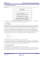
frame structure, of type can_std_frame_t, is provided by the API header file and has the following structure:
typedef struct
{
uint32_t id;
uint8_t dlc;
uint8_t data[8];
} can_frame_t;
Note that the timestamp is not included in this structure, but can easily be added.
Aside from CAN bus arbitration, priority is determined using the lowest mailbox number - except for SH (RCAN-ET)
where the highest mailbox has priority. This is true for both transmit and receive operations. If two mailboxes have
been set with the same CAN ID, the lowest mailbox number has the highest priority. Because of this, tf two mailboxes
are configured to receive with the same ID, one mailbox will never receive a message.
5.
Using Extended ID
To use extended ID, the FRAME_ID_MODE must be set as explained in 0 below.
When Extended CAN is enabled, the API functions ending in ‘Xid’ can be called. These functions will automatically
cause the ID field of the CAN mailbox to be formatted to use extended ID. In other words the user need only call these
Xid-functions, and the ID value passed in the can_frame_t structure will be sent as a 29-bit ID (instead of 11-bit).
R01AN0339EU0203 Rev. 2.03
Mar 23, 2013
Page 4 of 29
RX600 Series
6.
CAN Application Programming Interface
Adding the CAN API to Your Project
Follow the steps below to add the CAN API code to your project. These steps assume that the Flash API has already
been added to your project.
1.
Copy the r_can_api directory (packaged with this application note) to your project directory.
2.
Add the file r_can_api.c to your project.
3.
Add an include path to the r_can_api directory.
4.
Add an include path to the r_can_api\src directory.
5.
Configure the middleware with config_r_can_api.h.
7.
The CAN Config File
It may be necessary to make modifications to the config_r_can_rapi.h file to customize the application
for the way you wish to run it. For example, there is the option of running in CAN polled mode or CAN
interrupt mode. config_r_can_rapi.h is the place where this is selected.
Do not change anything in the r_can_api.c file, which contains the Renesas CAN API functions for your Renesas
MCU.
Interrupts vs. Polling
USE_CAN_POLL
Include the macro USE_CAN_POLL if you want to poll CAN mailboxes for messages received and sent. Do not
include to use the CAN interrupts.
CAN Interrupt Settings
CAN0_INT_LVL
Sets the CAN interrupt level.
USE_CAN_API_SEARCH
Not implemented in the latest code releases to not cause confusion with the existing example code. If you have many
mailboxes configured and alot of CAN traffic, you may want to consider using this feature. Please see the MCU
hardware manual.
Max Time to Poll a Register
MAX_CANREG_POLLCYCLES
Max loops to poll a CAN register bit for expected value. If you are using polled mode, and If you wish to wait a certain
time to check that a mailbox has recieved a frame, increase this value. This can be set to a very low value, but do not set
to zero or the mailbox may not be chacded at all.!
Transceiver Control Pin Mapping
TRANSCEIVER STANDBY, TRANSCEIVER ENABLE
Specify where you have the transceiver control pins connected. Some transceivers may have other control pins. You
would have to configure this yourself.
Using Standard/Extended ID
FRAME_ID_MODE
Select what type of CAN ID type to enable in the driver, that is, usage of 11-bit or 29-bit IDs.
FRAME_ID_MODE can be set to STD_ID_MODE, EXT_ID_MODE, or MIXED_ID_MODE. The first two settings
enable only those functions belonging to that ID mode. If it is set to mixed mode, the whole API becomes available. It is
preferable to not set mixed mode for the driver if it is to be used in a network using only one ID type. Messages with the
wrong ID type for the network will only cause wasted bandwidth (no node will receive them).
R01AN0339EU0203 Rev. 2.03
Mar 23, 2013
Page 5 of 29
RX600 Series
CAN Application Programming Interface
CAN Bitrate Settings
See API R_CAN_SetBitrate below and the file config_r_can_rapi.h.
8.
The CAN API
The API is a set of functions that allow you to use CAN without having to commit attention to all the details of setting
up the CAN peripheral, to be able to easily have your application communicate with other nodes on the network.
Initialization, Port and Peripheral Control
R_CAN_Create (uint32_t ch_nr);
R_CAN_PortSet (uint32_t ch_nr, uint32_t action_type );
[action_type = ENABLE, DISABLE]
R_CAN_Control (uint32_t ch_nr, uint32_t action_type );
[action_type = ENTERSLEEP_CANMODE, EXITSLEEP_CANMODE, RESET_CANMODE,
HALT_CANMODE, OPERATE_CANMODE, CANPORT_TEST_LISTEN_ONLY,
CANPORT_TEST_0_EXT_LOOPBACK, CANPORT_TEST_1_INT_LOOPBACK,
CANPORT_RETURN_TO_NORMAL]
R_CAN_SetBitrate (uint32_t ch_nr);
Send
R_CAN_TxSet (uint32_t ch_nr, uint32_t mbox_nr, can_std_frame_t* frame_p, uint32_t frame_type);
R_CAN_TxSetXid (uint32_t ch_nr, uint32_t mbox_nr, can_frame_t* frame_p, uint32_t frame_type);
R_CAN_Tx (uint32_t ch_nr, uint32_t mbox_nr);
R_CAN_TxCheck (uint32_t ch_nr, uint32_t mbox_nr);
R_CAN_TxStopMsg (uint32_t ch_nr, uint32_t mbox_nr);
Receive
R_CAN_RxSet (uint32_t ch_nr, uint32_t mbox_nr, uint32_t stid,
uint32_t frame_type);
R_CAN_RxSetXid (uint32_t ch_nr, uint32_t mbox_nr, uint32_t xid, uint32_t frame_type);
R_CAN_RxRead (uint32_t ch_nr, uint32_t mbox_nr, can_std_frame_t* frame_p);
R_CAN_RxPoll (uint32_t ch_nr, uint32_t mbox_nr);
R_CAN_RxSetMask (uint32_t ch_nr, uint32_t sid_mask_value, uint32_t mask_reg_nr);
Error Check
R_CAN_CheckErr (uint32_t ch_nr);
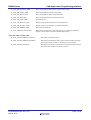
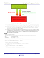
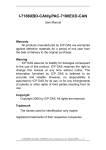
Figure 2. The CAN API functions.
Note that the hardware manual is the absolute reference for behavior.
The first group of functions (orange) in Figure 2 is used to initialize the CAN peripheral registers and configure the
MCU’s CAN and transceiver ports. The first function, R_CAN_Create, will by default invoke the rest of the
initialization functions.
The Transmit functions (blue) are used to set up a mailbox to transmit and to check that it actually was sent successfully.
The Receive functions (green) are used to set up a mailbox to receive and to retrieve a message from it.
The Error function (red) checks the CAN bus status of the node.
8.1
API Return Codes
R_CAN_OK
Action completed successfully.
R_CAN_NOT_OK
Action did not complete successfully.
Usually a more specific return code is used, see below.
R_CAN_SW_BAD_MBX
Bad mailbox number.
R_CAN_BAD_CH_NR
The channel number does not exist.
R_CAN_BAD_ACTION_TYPE
No such action type exists for this function.
R_CAN_MSGLOST
Message was overwritten or lost.
R_CAN_NO_SENTDATA
No message was sent.
R_CAN_RXPOLL_TMO
Polling for received message timed out.
R01AN0339EU0203 Rev. 2.03
Mar 23, 2013
Page 6 of 29
RX600 Series
CAN Application Programming Interface
R_CAN_SW_WAKEUP_ERR
The CAN peripheral did not wake up from Sleep mode.
R_CAN_SW_SLEEP_ERR
The CAN peripheral did enter Sleep mode.
R_CAN_SW_HALT_ERR
The CAN peripheral did not enter Halt mode.
R_CAN_SW_RST_ERR
The CAN peripheral did not enter Reset mode.
R_CAN_SW_TSRC_ERR
Time Stamp error.
R_CAN_SW_SET_TX_TMO
Waiting for previous transmission to finish timed out.
R_CAN_SW_SET_RX_TMO
Waiting for previous reception to complete timed out.
R_CAN_SW_ABORT_ERR
Wait for abort timed out.
R_CAN_MODULE_STOP_ERR
Whole CAN peripheral is in stop state (low power). Perhaps the PRCR
register was not used to unlock the module stop register.
CAN bus status return codes
R_CAN_STATUS_ERROR_ACTIVE
Bus Status: Normal operation.
R_CAN_STATUS_ERROR_PASSIVE
Bus Status: The node has sent at least 127 Error frames for either
the Transmit Error Counter, or the Receive Error Counter.
R_CAN_STATUS_BUSOFF
Bus Status: The node’s Transmit Error Counter has surpassed 255
due to the node’s failure to transmit correctly.
R01AN0339EU0203 Rev. 2.03
Mar 23, 2013
Page 7 of 29
RX600 Series
CAN Application Programming Interface
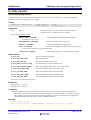
R_CAN_Create
Initializes the CAN peripheral, sets bitrate, masks, mailbox defaults and configures
CAN interrupts
This function will by default invoke the rest of the initialization functions. It also sets the CAN interrupt levels. It will
also call all other relevant set-up functions such as
• R_CAN_SetBitrate()
• R_CAN_RxSetMask ()
• R_CAN_PortSet ()
Format
uint32_t R_CAN_Create(const uint32_t ch_nr);
Arguments
ch_nr
0,1,2,3
Which CAN bus to use. The number of available channels
depends on part. 1-4 channels may be available.
Return Values
R_CAN_OK
Action completed successfully.
R_CAN_SW_BAD_MBX
Bad mailbox number.
R_CAN_BAD_CH_NR
The channel number does not exist.
R_CAN_SW_RST_ERR
The CAN peripheral did not enter Reset mode.
R_CAN_MODULE_STOP_ERR
Whole CAN peripheral is in stop state (low power). Perhaps the PRCR
register was not used to unlock the module stop register.
See also R_CAN_Control return values.
Properties
Prototyped in r_can_api.h
Implemented in r_can_api.c
Comments
This function wakes the peripheral from CAN Sleep mode and puts it in CAN Reset mode. It configures the mailboxes
with these default settings:
• Overwrite an unread mailbox data when new frames arrive
• Sets the device to use ID priority (normal CAN behavior, not the optional mailbox number priority).
• Sets all mailboxes’ masks invalid.
R_CAN_Create calls the R_CAN_SetBitrate function and configures CAN interrupts if USE_CAN_POLL is
commented in config_r_can_rapi.h.
Before returning, it clears all mailboxes, sets the peripheral into Operation mode, and clears any errors.
Example
/* Init CAN. */
api_status = R_CAN_Create(0);
R01AN0339EU0203 Rev. 2.03
Mar 23, 2013
Page 8 of 29
RX600 Series
CAN Application Programming Interface
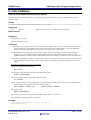
R_CAN_PortSet
Configures the MCU and transceiver port pins
This function is responsible for configuring the MCU and transceiver port pins. Transceiver port pins such as Enable
will vary depending on design, and this function must then be modified.
The function is also used to enter the CAN port test modes, such as Listen Only.
Format
uint32_t R_CAN_PortSet(
const uint32_t
const uint32_t
ch_nr,
action_type );
Arguments
ch_nr
0,1,2,3
Which CAN bus to use. The number of available channels
depends on part. 1-4 channels may be available.
action_type Port actions:
ENABLE
Enable the CAN port pins and the CAN transceiver.
DISABLE
Disable the CAN port pins and the CAN transceiver.
CANPORT_TEST_LISTEN_ONLY
sent. See 10.3.
Set to Listen Only mode. No Acks or Error frames are
CANPORT_TEST_0_EXT_LOOPBACK Use external bus and loopback. Not tested!
CANPORT_TEST_1_INT_LOOPBACK Only internal mailbox communication.
CANPORT_RETURN_TO_NORMAL
Return to normal port usage.
Return Values
R_CAN_OK
Action completed successfully.
R_CAN_SW_BAD_MBX
Bad mailbox number.
R_CAN_BAD_CH_NR
The channel number does not exist.
R_CAN_BAD_ACTION_TYPE
No such action type exists for this function.
R_CAN_SW_HALT_ERR
The CAN peripheral did not enter Halt mode.
R_CAN_SW_RST_ERR
The CAN peripheral did not enter Reset mode.
See also R_CAN_Control return values.
Properties
Prototyped in r_can_api.h
Implemented in r_can_api.c
Comments
Make sure this function is called before and after any default port set up function is used (e.g. ‘hwsetup’). Otherwise,
an output high/low on an MCU CAN port pin could affect the bus. (You may discover when debugging that a hard reset
on a node could cause other nodes to go into error mode. The reason may be that all ports were set as default output
hi/low before CAN reconfigures the ports. For a brief period of time, the ports will then be output low and disrupt the
CAN bus voltage level.)
You may have to change/add transceiver port pins according to your transceiver.
Example
/* Normal CAN bus usage. */
R_CAN_PortSet(0, ENABLE);
R01AN0339EU0203 Rev. 2.03
Mar 23, 2013
Page 9 of 29
RX600 Series
CAN Application Programming Interface
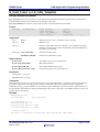
R_CAN_Control
Set CAN operating modes
Controls transition to CAN operating modes determined by the CAN Control register. For example, the Halt mode
should be used to later configure a receive mailbox.
Format
uint32_t R_CAN_Control(
const uint32_t
const uint32_t
ch_nr,
action_type );
Arguments
ch_nr
0,1,2,3
Which CAN bus to use. The number of available channels
depends on part. 1-4 channels may be available.
action_type Peripheral actions:
EXITSLEEP_CANMODE
peripheral starts up. See 12.
Exit CAN Sleep mode, the default state when the
ENTERSLEEP_CANMODE
Enter CAN Sleep mode to save power.
RESET_CANMODE
Put the CAN peripheral into Reset mode.
HALT_CANMODE
Put the CAN peripheral into Halt mode. CAN peripheral
is still connected to the but stops communicating.
OPERATE_CANMODE
Put the CAN peripheral into normal Operation mode.
Return Values
R_CAN_OK
Action completed successfully.
R_CAN_SW_BAD_MBX
Bad mailbox number.
R_CAN_BAD_CH_NR
The channel number does not exist.
R_CAN_BAD_ACTION_TYPE
No such action type exists for this function.
R_CAN_SW_WAKEUP_ERR
The CAN peripheral did not wake up from Sleep mode.
R_CAN_SW_SLEEP_ERR
The CAN peripheral did not enter Sleep mode.
R_CAN_SW_RST_ERR
The CAN peripheral did not enter Halt mode.
R_CAN_SW_HALT_ERR
The CAN peripheral did not enter Halt mode.
R_CAN_SW_RST_ERR
The CAN peripheral did not enter Reset mode.
See also R_CAN_PortSet return values.
Properties
Prototyped in r_can_api.h
Implemented in r_can_api.c
Comments
Other than calling this API to enter Halt mode, CAN mode transitions are called via the other API functions
automatically. For example, the default mode when starting up is CAN Sleep mode. Use the API to switch to
other operating modes, for example first ‘Exit Sleep’ followed by ‘Reset‘ to initialize the CAN registers for
bitrate and interrupts, then enter ‘Halt’ mode to configure mailboxes.
Example
/* Normal CAN bus usage. */
result = R_CAN_Control(0, OPERATE_CANMODE); //Check that result is = R_CAN_OK.
R01AN0339EU0203 Rev. 2.03
Mar 23, 2013
Page 10 of 29
RX600 Series
CAN Application Programming Interface
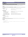
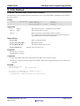
R_CAN_SetBitrate
Sets the CAN bitrate (communication speed)
The baud rate and bit timing must always be set during the configuration process. It can be changed later on if reset
mode is entered.
Format
void R_CAN_SetBitrate(const uint32_t ch_nr);
Arguments
ch_nr
0,1,2,3
Which CAN bus to use. 1-4 channels may be available.
Return Values
-
Properties
Prototyped in r_can_api.h
Implemented in r_can_api.c
Comments
A Time quanta, Tq, is one bit-time of the CAN system clock, fcanclk. This is not the CAN bit-time but the internal
clock period of the CAN peripheral. This CAN system clock in turn is determined by (twice) the Baud Rate
Prescaler value and the peripheral bus clock, fclk, to create the CAN system clock.
Setting the baud rate or data speed on the CAN bus requires some understanding of CAN bit timing and MCU
frequency, as well as reading hardware manual figures and tables. The default bitrate setting of the API is
500kB, and unless the MCU clock or peripheral frequencies are changed, it is sufficient to just call the function.
One bit time is divided into a number of Time Quanta, Tqtot. One Time Quantum is equal to the period of the CAN
clock. Each bitrate register is then given a certain number of Tq of the total of Tq that make up one CAN bit
period.
Formulas to calculate the bitrate register settings.
PCLK is the peripheral clock frequency.
fcan = PCLK
The prescaler scales the CAN peripheral clock down with a factor.
fcanclk = fcan/prescaler
One Time Quantum is one clock period of the CAN clock.
Tq =1/fcanclk
Tqtot is the total number of CAN peripheral clock cycles during one CAN bit time and is by the peripheral built by
the sum of the “time segments” and “SS” which is always 1.
Tqtot = TSEG1 + TSEG2 + SS
(TSEG1 must be > TSEG2)
The bitrate is then
Bitrate = fcanclk/Tqtot
SS is always 1. SJW is often given by the bus administrator. Select 1 <= SJW <= 4.
See CONFIG_R_CAN_RAPI.H for more details.
Example
/* Set bitrate as defined in config_r_can_rapi.h. */
R_CAN_SetBitrate(0);
R01AN0339EU0203 Rev. 2.03
Mar 23, 2013
Page 11 of 29
RX600 Series
CAN Application Programming Interface
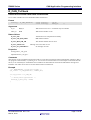
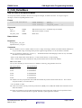
R_CAN_TxSet and R_CAN_TxSetXid
Set up a mailbox to transmit
R_CAN_TxSet will write to a mailbox the specified ID, data length and data frame payload, then set the mailbox to
transmit mode and send a frame onto the bus by calling R_CAN_Tx().
R_CAN_TxSetXid does the same, except if this function is used, the ID will be a 29-bit ID.
Format
uint32_t
R_CAN_TxSet(
const
const
const
const
uint32_t
uint32_t
can_frame_t*
uint32_t
ch_nr,
mbox_nr,
frame_p,
frame_type
);
Arguments
ch_nr
0,1,2,3
Which CAN bus to use. 1-4 channels may be available.
mbox_nr
0-32
Mailbox to use.
frame_p*
Pointer to a data frame structure in memory. It is an address to the data
structure containing the ID, DLC and data that constitute the dataframe
the mailbox will transmit.
frame_type DATA_FRAME
Send a normal data frame.
REMOTE_FRAME
Send a remote data frame request.
Return Values
R_CAN_OK
The mailbox was set up for transmission.
R_CAN_SW_BAD_MBX
Bad mailbox number.
R_CAN_BAD_CH_NR
The channel number does not exist.
R_CAN_BAD_ACTION_TYPE
No such action type exists for this function.
Properties
Prototyped in r_can_api.h
Implemented in r_can_api.c
Comments
This function first waits for any previous transmission of the specified mailbox to complete. It then interrupt disables
the mailbox temporarily when setting up the mailbox: Sets the ID value for the mailbox, the Data Length Code
indicated by frame_p, selects dataframe or remote frame request and finally copies the data frame payload bytes (0-7)
into the mailbox. The mailbox is interrupt enabled again unless USE_CAN_POLL was defined. Finally R_CAN_Tx is
called to deliver the message.
Example
#define MY_TX_SLOT
can_std_frame_t
7
my_tx_dataframe;
my_tx_dataframe.id = 1;
my_tx_dataframe.dlc = 2;
my_tx_dataframe.data[0] = 0xAA;
my_tx_dataframe.data[1] = 0xBB;
/* Send my frame. */
api_status = R_CAN_TxSet(0, MY_TX_SLOT, &my_tx_dataframe, DATA_FRAME);
R01AN0339EU0203 Rev. 2.03
Mar 23, 2013
Page 12 of 29
RX600 Series
CAN Application Programming Interface
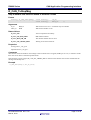
R_CAN_Tx
Starts actual message transmission onto the CAN bus
This API will wait until the mailbox finishes handling a prior frame, then set the mailbox to transmit mode.
Format
uint32_t
R_CAN_Tx(
const uint32_t
const uint32_t
ch_nr,
mbox_nr
);
Arguments
ch_nr
0,1,2,3
Which CAN bus to use. 1-4 channels may be available.
mbox_nr
0-32
Which CAN mailbox to use.
Return Values
R_CAN_OK
The mailbox was set to transmit a previously configured mailbox.
R_CAN_SW_BAD_MBX
Bad mailbox number.
R_CAN_BAD_CH_NR
The channel number does not exist.
R_CAN_SW_SET_TX_TMO
Waiting for previous transmission to finish timed out.
R_CAN_SW_SET_RX_TMO
Waiting for previous reception to complete timed out.
Properties
Prototyped in r_can_api.h
Implemented in r_can_api.c
Comments
R_CAN_TxSet must have been called at least once for this mailbox after system start to set up the mailbox content, as
this function only tells the mailbox to send its content.
Example
#define MY_TX_SLOT
7
/* Send mailbox content. This mailbox is presumed to have been set up to send some time
in the past. */
R_CAN_Tx(0, MY_TX_SLOT);
R01AN0339EU0203 Rev. 2.03
Mar 23, 2013
Page 13 of 29
RX600 Series
CAN Application Programming Interface
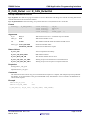
R_CAN_TxCheck
Check for successful data frame transmission.
Use to check a mailbox for a successful data frame transmission.
Format
uint32_t
R_CAN_TxCheck(
const uint32_t
const uint32_t
ch_nr,
mbox_nr
);
Arguments
ch_nr
0,1,2,3
Which CAN bus to use. 1-4 channels may be available.
mbox_nr
0-32
Which CAN mailbox to use.
Return Values
R_CAN_OK
Transmission was completed successfully.
R_CAN_SW_BAD_MBX
Bad mailbox number.
R_CAN_BAD_CH_NR
The channel number does not exist.
R_CAN_MSGLOST
R_CAN_NO_SENTDATA
Message was overwritten or lost.
No message was sent.
Properties
Prototyped in r_can_api.h
Implemented in r_can_api.c
Comments
This function is only needed if an application needs to verify that a message has been transmitted for example so that it
can progress a state machine, or if messages are sent back-to-back. With CAN’s level of transport control built into the
silicon, it can reasonably be assumed that once a mailbox has been asked to send with the API that the message will
indeed be sent. Safest if of course to use this function after a transmission.
Example
/*** TRANSMITTED a particular frame? */
api_status = R_CAN_TxCheck(0, CANBOX_TX);
if (api_status == R_CAN_OK)
{
/* Notify main application. */
message_x_sent_flag = TRUE;
}
R01AN0339EU0203 Rev. 2.03
Mar 23, 2013
Page 14 of 29
RX600 Series
CAN Application Programming Interface
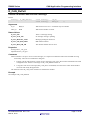
R_CAN_TxStopMsg
Stop a mailbox that has been asked to transmit a frame
Format
uint32_t R_CAN_TxStopMsg(
const uint32_t
const uint32_t
ch_nr,
mbox_nr
);
Arguments
ch_nr
0,1,2,3
Which CAN bus to use. 1-4 channels may be available.
mbox_nr
0-32
Which CAN mailbox to use.
Return Values
R_CAN_OK
Action completed successfully.
R_CAN_SW_BAD_MBX
Bad mailbox number.
R_CAN_BAD_CH_NR
The channel number does not exist.
R_CAN_SW_ABORT_ERR
Waiting for an abort timed out.
Properties
Prototyped in r_can_api.h
Implemented in r_can_api.c
Comments
This function clears the mailbox control flags so that a transmission is stopped (TrmReq is set to 0.) A software counter
then waits for an abort a maximum period of time.
If the message was not stopped, R_CAN_SW_ABORT_ERR is returned. Note that the cause of this could be that the
message was already sent.
Example
R_CAN_TxStopMsg(0, MY_TX_SLOT);
R01AN0339EU0203 Rev. 2.03
Mar 23, 2013
Page 15 of 29
RX600 Series
CAN Application Programming Interface
R_CAN_RxSet and R_CAN_RxSetXid
Set up a mailbox to receive
R_CAN_RxSet The API sets up a given mailbox to receive data frames with the given CAN ID. Incoming data frames
with the same ID will be stored in the mailbox.
R_CAN_RxSetXid does the same thing, except if this function is used, the ID will be a 29-bit ID.
Format
uint32_t
R_CAN_RxSet(
const
const
const
const
uint32_t
uint32_t
uint32_t
uint32_t
ch_nr,
mbox_nr,
id,
frame_type
);
Arguments
ch_nr
0,1,2,3
Which CAN bus to use. 1-4 channels may be available.
mbox_nr
0-32
Which CAN mailbox to use.
sid
0-7FFh
The standard CAN ID which the mailbox should receive.
frame_type DATA_FRAME
Send a normal data frame.
REMOTE_FRAME
Send a remote data frame request.
Return Values
R_CAN_OK
Action completed successfully.
R_CAN_SW_BAD_MBX
Bad mailbox number.
R_CAN_BAD_CH_NR
The channel number does not exist.
R_CAN_SW_SET_TX_TMO
Waiting for previous transmission to finish timed out.
R_CAN_SW_SET_RX_TMO
Waiting for previous reception to complete timed out.
Properties
Prototyped in r_can_api.h
Implemented in r_can_api.c
Comments
The function will first wait for any previous transmission/reception to complete, then temporarily interrupt disable
the mailbox. It sets the mailbox to the given standard ID value, and whether to receive normal CAN dataframes or
remote frame requests.
Example
#define MY_RX_SLOT
#define SID_FAN_SPEED
8
0x10
R_CAN_RxSet(0, MY_RX_SLOT, SID_FAN_SPEED, DATA_FRAME);
R01AN0339EU0203 Rev. 2.03
Mar 23, 2013
Page 16 of 29
RX600 Series
CAN Application Programming Interface
R_CAN_RxPoll
Checks if a mailbox has received a message
Format
uint32_t
R_CAN_RxPoll(
const uint32_t
const uint32_t
ch_nr,
mbox_nr
);
Arguments
ch_nr
0,1,2,3
Which CAN bus to use. 1-4 channels may be available.
mbox_nr
0-32
Which CAN mailbox to check.
Return Values
R_CAN_OK
There is a message waiting.
R_CAN_NOT_OK
No message waiting or pending.
R_CAN_RXPOLL_TMO
Message pending but timed out.
R_CAN_SW_BAD_MBX
Bad mailbox number.
R_CAN_BAD_CH_NR
The channel number does not exist.
Properties
Prototyped in r_can_api.h
Implemented in r_can_api.c
Comments
When a mailbox is set up to receive certain messages, it is important to determine when it has finished receiving
successfully. There are two methods for doing this:
1.
Polling. Call the API regularly to check for new messages. USE_CAN_POLL must be defined in the CAN
configuration file. If there is a message use R_CAN_RxRead to fetch it.
2.
Using the CAN receive interrupt (USE_CAN_POLL not defined): Use this API to check which mailbox
received. Then notify the application.
The function returns R_CAN_OK if new data was found in the mailbox.
Example
See example in R_CAN_RxRead.
R01AN0339EU0203 Rev. 2.03
Mar 23, 2013
Page 17 of 29
RX600 Series
CAN Application Programming Interface
R_CAN_RxRead
Read the CAN data frame content from a mailbox
The API checks if a given mailbox has received a message. If so, a copy of the mailbox’s dataframe will be written to
the given structure.
Format
uint32_t
R_CAN_RxRead( const uint32_t
const uint32_t
can_std_frame_t * const
ch_nr,
mbox_nr,
frame_p
);
Arguments
ch_nr
0,1,2,3
Which CAN bus to use. 1-4 channels may be available.
mbox_nr
0-32
Which CAN mailbox to check.
frame_p
*
Refers to a pointer to a data frame structure in memory.
It is an address to the data structure into which the function will place a
copy of the mailbox’s received CAN dataframe.
Return Values
R_CAN_OK
There is a message waiting.
R_CAN_SW_BAD_MBX
Bad mailbox number.
R_CAN_BAD_CH_NR
The channel number does not exist.
R_CAN_MSGLOST
Message was overwritten or lost.
Properties
Prototyped in r_can_api.h
Implemented in r_can_api.c
Comments
Use R_CAN_PollRxCAN() first to check whether the mailbox has received a message.
This function is used to fetch the message from a mailbox, either when using polled mode or from a CAN receive
interrupt.
Example
#define MY_RX_SLOT
can_std_frame_t
8
my_rx_dataframe;
api_status = R_CAN_RxPoll(0, CANBOX_RX_DIAG);
if (api_status == R_CAN_OK)
R_CAN_RxRead(0, CANBOX_RX_DIAG, &my_rx_dataframe);
R01AN0339EU0203 Rev. 2.03
Mar 23, 2013
Page 18 of 29
RX600 Series
CAN Application Programming Interface
R_CAN_RxSetMask
Sets the CAN ID Acceptance Masks
To accept only one ID, set mask to all ones. To accept all messages, set mask to all zeros. To accept a range of
messages, set the corresponding ID bits to zero.
Format
void R_CAN_RxSetMask(
const uint32_t
const uint32_t
const uint32_t
ch_nr,
mbox_nr,
sid_mask_value
);
Arguments
ch_nr
0,1,2,3
Which CAN bus to use. 1-4 channels may be available.
mbox_nr
0-32
Which CAN mailbox to check.
sid_mask_value
0-7FFh
Mask value.
Return Values
-
Properties
Prototyped in r_can_api.h
Implemented in r_can_api.c
Comments
Receive mailboxes can use a mask to filter out one or a range of message CAN IDs. The mask enables mailboxes to
accept a broader range of messages than just the single message ID that is set in the mailbox’s ID field.
There is one mask for mailbox 0-3, one for 4-7, … Remember therefore that changing a mask can very well affect
the behavior of adjacent mailboxes.
- Each '0' in the mask means "mask this bit", or “don't look at that bit”; accept anything.
- Each '1' means check if the CAN-ID bit in this position matches the CAN-ID of the mailbox.
How to set a mask
Lets say the CAN-IDs you want to receive in a mailbox is 700-704h using standard 11-bit ID:
Hex representation
Bit representation
0x700
011100000000b
0x701
011100000001b
0x702
011100000010b
0x703
011100000011b
0x704
011100000100b
The mailbox will only accept frames with an ID that matches the positions whose mask value is 1. If we want to
accept all of above, we set the mask as
011111111000b, or 07F8h.
The CAN receive filter will only look at bit positions b11 (MSB), to b3 (LSB) and whether these match the receive
ID of the mailbox.
If we then set a mailbox to receive ID 0x700 (0x700-0x707 will give the same result) it will accept IDs 0x700 to
0x707. 0x705 to 0x707 must later be ignored ‘manually’ by the application software.
R01AN0339EU0203 Rev. 2.03
Mar 23, 2013
Page 19 of 29
RX600 Series
CAN Application Programming Interface
Fast filtering of messages with Acceptance Filter Support
If you have used a mask to receive a broad range of message IDs, you must filter for the actual desired messages
with firmware. To increase the speed of this search one may use the Acceptance Filter Support instead.
The Acceptance Filter Support Unit (ASU) provides a faster search compared to software filtering of messages
using a mask (with the R_CAN_RxSetMask API). Software filtering can be time consuming as the Standard
ID bits are rearranged and not stored as a normal word in memory. Another problem could be that the
acceptance mask may not be able to be set to receive the particular combination of messages you want. If you
set the mask to accept all messages you may have to ‘waste’ time by checking a long list of the messages using
software for each incoming ID. This manual filtering’ would also involve having all the IDs in a readable
format. An efficient solution in such cases is to use the Acceptance Filter Support Unit.
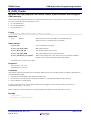
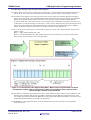
To use it, one writes the CAN-ID as it is stored in the message box into the ASU. When read back from the ASU
register it reads:
Bit 0-7 = Table Address Search Info, ‘ASI’
Bit 8-15 = Bit Search Information, ‘BSI’. SID0-3 has now been converted to a bit position to enable faster
table searches. Use the output to search through a table.
Figure 3. The Acceptance Filter Support Unit (ASU). When read, the representation of the ID
is formatted to enable a fast search through a table. This provides a faster response than a
search through a ‘normal’ array of CAN IDs.
The search table. A table must be prepared by the user to check whether an ID is of interest to the application. The
firmware must search the table at each byte address ASI and bit position BSI. If a bit BSI-value is set in the
user’s table, the bit pattern matches the BSI pattern of the register which means the address is of interest to the
node, and the frame should be processed by the application.
See REJ05B0276 “CAN Application Note” for more information on how to use the ASU. (Download from
www.renesas.com,
R01AN0339EU0203 Rev. 2.03
Mar 23, 2013
Page 20 of 29
RX600 Series
CAN Application Programming Interface
R_CAN_CheckErr
Check for bus errors
The API checks the CAN status, or Error State, of the CAN peripheral.
Format
uint32_t
R_CAN_CheckErr(const uint32_t
ch_nr);
Parameters
ch_nr
0,1,2,3
Which CAN bus to use. 1-4 channels may be available.
urn Values
CAN_STATE_ERROR_ACTIVE
CAN Bus Status: Normal operation.
CAN_STATE_ERROR_PASSIVE
CAN Bus Status: The node has sent at least 127 Error frames for either the
Transmit Error Counter, or the Receive Error Counter.
CAN_STATE_BUSOFF
CAN Bus Status: The node’s Transmit Error Counter has surpassed 255
due to the node’s failure to transmit correctly.
Properties
Prototyped in r_can_api.h
Implemented in r_can_api.c
Comments
The API checks the CAN status flags of the CAN peripheral and returns the status error code. It tells whether the
node is in a functioning state or not and is used for application error handling.
It should be polled either routinely from the main loop, or via the CAN error interrupt. Since the peripheral
automatically handles retransmissions and Error frames it is usually of no advantage to include an error
interrupt routine.
If an error state is encountered the application can just wait and monitor for the peripheral to recover, as the CAN
peripheral takes itself on or off line depending on its state. After a recovery is discovered, the application
should restart.
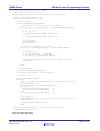
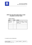
Bus States
CAN is designed to protect network communication in the event that any CAN network node becomes faulty.
Every time the transmitter sees an Error flag, the Transmit Error Counter is increased, and when an error in a
received frame is detected, the Receive Error Counter is increased. The Transmit and Receive Error Counters
are respectively decreased with every successfully transmitted or received frame. In both the Error Active state
(the normal operating state) and the Error Passive State, messages can be transmitted and received.
R01AN0339EU0203 Rev. 2.03
Mar 23, 2013
Page 21 of 29
RX600 Series
CAN Application Programming Interface
Error Active
Normal
TEC or REC < 128
11 consecutive
recessive bits
detected 128 times
TEC or REC > 127
Error Passive
No Errors sent
TEC > 255
Bus Off
No communication
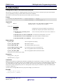
Figure 4. CAN Error States.
Error Active
When a node is in Error Active state it communicates with the bus normally. If the unit detects an error, it
transmits an active Error flag. Once it counts 127 errors, it switches to the Error Passive state.
Error Passive
When either error counter exceeds 128, the CAN status for that node changes to state Error passive, and
messages can still can be transmitted and received, but the node will not send Error frames. Error frames are
invisible to the user and are taken care of by the peripheral silicon.
Bus Off
If the transmit error counter exceeds 255, the CAN node enters the Bus Off state. This prevents a faulty node
from causing a bus failure. When serious problems cause a CAN node to enter the Bus Off state, no messages
can be transmitted or received by that node until it detects 11 consecutive ‘recessive’ bits 128 times, or until
the peripheral is reset. When the application detects a recovery from Bus Off, the user should reinitialize all
registers of the CAN module, and restart the application.
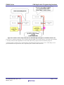
Using CAN Polling
Call the API regularly to check the CAN state for the application, so it does not try to communicate if the node is
Bus Off. In the following, it is assumed that HandleCanBusState is called once every loop of the main
application.
R01AN0339EU0203 Rev. 2.03
Mar 23, 2013
Page 22 of 29
RX600 Series
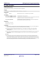
CAN Application Programming Interface
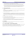
Figure 5. Handling recovery from Bus Off for the application.
(The MCU detects recovery of the bus on its own.)
A node will automatically resume the normal Error Active state again after seeing 11 consecutive recessive bits on
the bus 128 times. Note that the time a node spends in Bus Off could be very short, e.g. less than a millisecond.
Poll with the Check Error function once every cycle in the main routine what state the node is in (or use the CAN
error interrupt). If the node has reached Bus Off a certain number of times within a certain time period, you
may want to send a warning message, light an LED etc.
The minimum action required of a node if Bus Off is reached is shown above. Stop trying to communicate and poll
the peripheral with the Check Error function to see when the peripheral has returned to the normal Error Active
state. When the node has recovered, it is important to reinitialize the CAN peripheral and the application to
make sure the slots are in a known state.
Example
uint8_t error_bus_status;
/*****************************************************************************
Name:
HandleCanBusState
Parameters:
Bus number, 0 or 1.
Returns:
Description:
Check CAN peripheral bus state.
*****************************************************************************/
static void HandleCanBusState(uint8_t ch_nr)
{
can_std_frame_t err_tx_dataframe;
/* Has the status register reached error passive or more? */
if (ch_nr == 0)
error_bus_status[ch_nr] = R_CAN_CheckErr(0);
/*else
error_bus_status[ch_nr] = R_CAN1_CheckErr(1);*/
R01AN0339EU0203 Rev. 2.03
Mar 23, 2013
Page 23 of 29
RX600 Series
CAN Application Programming Interface
/* Tell user if CAN bus status changed.
All Status bits are read only. */
if (error_bus_status[ch_nr] != error_bus_status_prev[ch_nr])
{
switch (error_bus_status[ch_nr])
{
/* Error Active. */
case R_CAN_STATUS_ERROR_ACTIVE:
/* Only report if there was a previous error. */
if (error_bus_status_prev[ch_nr] > R_CAN_STATUS_ERROR_ACTIVE)
{
if (ch_nr == 0)
DisplayString(LCD_LINE1, "bus0: OK");
else
DisplayString(LCD_LINE2, "bus1: OK");
/* Show user */
Delay(0x400000);
}
/* Restart if returned from Bus Off. */
if (error_bus_status_prev[ch_nr] == R_CAN_STATUS_BUSOFF)
{
/* Restart CAN */
if (R_CAN_Create(0) != R_CAN_OK)
app_err_nr |= APP_ERR_CAN_PERIPH;
/* Restart CAN demos even if only one channel failed. */
InitCanApp();
}
break;
/* Error Passive. */
case R_CAN_STATUS_ERROR_PASSIVE:
/* Continue into Bus off case to display. */
/* Bus Off. */
case R_CAN_STATUS_BUSOFF:
default:
/* The application should take note of the following state and
Stop communication. */
app_state[ch_nr] = R_CAN_STATUS_BUSOFF;
if (ch_nr == 0)
DisplayString(LCD_LINE1,"bus0:
");
else
DisplayString(LCD_LINE2,"bus1:
");
/* Show user */
LcdShow2DigHex((uint8_t)error_bus_status[ch_nr], ch_nr*16 + 6);
Delay(0x400000);
nr_times_reached_busoff[ch_nr]++;
break;
}
error_bus_status_prev[ch_nr] = error_bus_status[ch_nr];
}/* end HandleCanBusState() */
Using CAN Error Interrupts.
R01AN0339EU0203 Rev. 2.03
Mar 23, 2013
Page 24 of 29
RX600 Series
CAN Application Programming Interface
The CAN error interrupt can be used to check the error state of the node, although polling with the API regularly is
usually sufficient since low level error handling is done by the peripheral.
The API can be called from the error ISR to determine the error state, and then flag the application if a state
transition has occurred. Most often the Transmit or Receive Error Counter will have just incremented.
Interrupts can be enabled separately for each of: A single error, transition to Error Passive, and transition to Bus
Off. If the first of these, the CAN Error interrupt is enabled, an interrupt is generated each time an error is
detected. Again, generating this interrupt is usually unnecessary as CAN handles errors on its own.
9.
CAN Interrupt Checklist
6.
Use this checklist to make sure interrupts are set up correctly, and if you are having problems getting the interrupts
to trigger.
7.
Tell the compiler to do a ‘return from interrupt’ for your ISR with the #pragma directive. This must be present in
the file where the function is defined. Example:
#pragma interrupt CAN0_RXM0_ISR(vect=VECT_CAN0_RXM0, enable)
void CAN0_RXM0_ISR(void)
{…
8.
Are interrupts enabled globally with e.g. the ENABLE_IRQ macro somewhere? If your interrupt does not occur,
the flag may have been disabled (by e.g. DISABLE_IRQ). Check by doing this: At a point in the code where your
interrupt is expected, set a breakpoint and check that the I-flag is '1'. Check the CPU flag registers for the I-flag.
9.
Is the interrupt priority level for the interrupt set to a non-zero value? Check the main Interrupt chapter of the HW
manual.
10. Is the respective mailbox’s interrupt flag enabled?
11. Is the CAN interrupt mask register set to mask off the interrupt?
12. To nest CAN interrupts, that is, enable other interrupts to preempt an ongoing CAN interrupt, add the “enable”
argument to the vector declaration as in the example above.
13. Make sure that the interrupt ISR function is pointed to correctly by the vector table. Check the interrupt base
register and count the offset from there to see the CAN interrupt ISR address in the interrupt table.
10. Test Modes
There are test modes that may be useful for example during product development. There are two loopback modes
“Internal” and “External”, and also a Listen only mode.
10.1
Internal Loopback - Test Node Without CAN Bus
Internal Loopback mode, or Self Test mode, allows you to communicate via the CAN mailboxes without connecting to
a bus. This can be useful for testing an application, or self-diagnosis during application debug.
The node acknowledges its own data with the ACK bit in the data frame. The node also stores its own transmitted
messages into a receive mailbox if it was configured for that CAN ID. This is normally not possible.
R01AN0339EU0203 Rev. 2.03
Mar 23, 2013
Page 25 of 29
RX600 Series
CAN Application Programming Interface
Figure 6. CAN Internal Loopback mode.
This lets you test the functionality of a node without having a CAN bus connected.
Internal Loopback can be convenient when testing as this mode allows the CAN controller to run without sending CAN
errors due to no Acks received when the node is alone on the bus, it acknowledges transmitted frames itself.
10.2
External Loopback - Test Lone Node On Bus
External Loopback is like Internal Loopback with the only difference that there must be a CAN bus connected to the
node. The messages are acknowledged by the node so the node can be alone on the bus. This is an advantage as nodes
can be tested standalone.
Figure 7. External Loopback. The message is transmitted onto the CAN bus and can be received
back on the same node. This is convenient when testing code and when a node is alone on the bus.
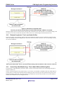
10.3
Listen Only (Bus Monitoring) - Test a Node Without Affecting Bus
In Listen Only, or Bus Monitoring, the node is quiet. A node in Listen Only mode will not acknowledge messages or
send Error frames etc.
Caution: Mark entering listen only mode clearly in your code so you remember to disable Listen Only mode again! If
you only have two nodes on the network and one of them goes into Listen Only, the other node will not get any Acks
and will eventually go Bus Off. Also, don’t request any transmissions in Listen Only as that is not a correct behavior
and the CAN module has not been designed for this.
R01AN0339EU0203 Rev. 2.03
Mar 23, 2013
Page 26 of 29
RX600 Series
CAN Application Programming Interface
Figure 8. A node in Listen Only mode will not acknowledge messages or send Error frames etc
Listen Only is useful for bringing up a new node that has been added to an existing CAN bus. The mode can be used for
a recently connected node’s application to ensure that frames have properly been received before going live.
A common usage is to detect a bus’s communication speed before letting the new unit go ‘live’. Listen Only is not a
part of the Bosch CAN specification, but is required by ISO-11898 for bitrate detection.
R01AN0339EU0203 Rev. 2.03
Mar 23, 2013
Page 27 of 29
RX600 Series
CAN Application Programming Interface
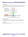
11. Time Stamp
The timestamp function captures the value of the on-chip time stamp to a mailbox when a message is received. By
examining the time stamp you can for example determine the sequence of messages if they are spread out over multiple
receive mailboxes to determine the order of the messages. Time stamp reading is not done by the API, so you will have
to poll the mailbox, and if the return value is R_CAN_OK (a message waiting) you can then go in and read the
timestamp.
Figure 9. CAN Timestamp is available in each mailbox.
12. CAN Sleep Mode
The default mode after an MCU reset is CAN Sleep mode. Use the API to switch to other operating modes, see the
R_CAN_Control API. Entering the CAN Sleep mode instantly stops the clock supply to the module and thereby
reduces power dissipation. All registers remain unchanged when the CAN module enters CAN sleep mode.
13. CAN FIFO
CAN FIFO buffering is available for the RX. 24 mailboxes can be configured for either transmission or reception. The
FIFO can be used by polling or with interrupts.
R01AN0339EU0203 Rev. 2.03
Mar 23, 2013
Page 28 of 29
RX600 Series
CAN Application Programming Interface
Website and Support
Renesas Electronics Website
http://www.renesas.com/
Inquiries
http://www.renesas.com/inquiry
All trademarks and registered trademarks are the property of their respective owners.
R01AN0339EU0203 Rev. 2.03
Mar 23, 2013
Page 29 of 29
Revision Record
Rev.
1.00
1.10
Date
Jun 1, 2010
Jun 6, 2011
1.11
Oct 2, 2011
2.00
Jan 10, 2011
2.01
May 16, 2012
Oct 10, 2012
2.02
Nov 13, 2012
2.03
Mar 23, 2013
Description
Page
Summary
—
First edition issued
AN# changed from REU05B0145 to R01AN0339EU.
Added RX62T and RX630 projects.
4
Changed CAPI_CFG_CAN_ISR to CAPI_CFG_CANx_ISR.
6
Added API return code "R_CAN_NOT_OK".
All
Changed “config_r_can_rap.h” to “config_r_can_rapi.h”.
Changed Properties to RX600 Series
1
All
Added Extended CAN.
5
RX63N workspace added.
Macros to be discontinued going forward (not needed):
- Changed text under USE_CAN_API_SEARCH
- Removed CAPI_CFG_CANx_ISR
All
Changes after RSKRX630 CAN App Note review.
(v.1.10 was reviewed, many were comments already fixed).
62G RSK CAN API Demo added.
Code
Went through all figures to increase visibility. Changed heading
AN
Chapter 3.
Code
Changed R_CAN_Control() sleep mode, to ensure that Halt
mode is entered before exiting sleep.
can_frame_t to cover both Standard and Ext frames.
Code
For RSK63N SW1 changed from P32 to P02.
A-1
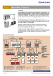
General Precautions in the Handling of MPU/MCU Products
The following usage notes are applicable to all MPU/MCU products from Renesas. For detailed usage notes on the
products covered by this document, refer to the relevant sections of the document as well as any technical updates that
have been issued for the products.
1. Handling of Unused Pins
Handle unused pins in accord with the directions given under Handling of Unused Pins in the manual.
⎯ The input pins of CMOS products are generally in the high-impedance state. In operation with an
unused pin in the open-circuit state, extra electromagnetic noise is induced in the vicinity of LSI, an
associated shoot-through current flows internally, and malfunctions occur due to the false
recognition of the pin state as an input signal become possible. Unused pins should be handled as
described under Handling of Unused Pins in the manual.
2. Processing at Power-on
The state of the product is undefined at the moment when power is supplied.
⎯ The states of internal circuits in the LSI are indeterminate and the states of register settings and
pins are undefined at the moment when power is supplied.
In a finished product where the reset signal is applied to the external reset pin, the states of pins
are not guaranteed from the moment when power is supplied until the reset process is completed.
In a similar way, the states of pins in a product that is reset by an on-chip power-on reset function
are not guaranteed from the moment when power is supplied until the power reaches the level at
which resetting has been specified.
3. Prohibition of Access to Reserved Addresses
Access to reserved addresses is prohibited.
⎯ The reserved addresses are provided for the possible future expansion of functions. Do not access
these addresses; the correct operation of LSI is not guaranteed if they are accessed.
4. Clock Signals
After applying a reset, only release the reset line after the operating clock signal has become stable.
When switching the clock signal during program execution, wait until the target clock signal has
stabilized.
⎯ When the clock signal is generated with an external resonator (or from an external oscillator)
during a reset, ensure that the reset line is only released after full stabilization of the clock signal.
Moreover, when switching to a clock signal produced with an external resonator (or by an external
oscillator) while program execution is in progress, wait until the target clock signal is stable.
5. Differences between Products
Before changing from one product to another, i.e. to a product with a different part number, confirm
that the change will not lead to problems.
⎯ The characteristics of an MPU or MCU in the same group but having a different part number may
differ in terms of the internal memory capacity, layout pattern, and other factors, which can affect
the ranges of electrical characteristics, such as characteristic values, operating margins, immunity
to noise, and amount of radiated noise. When changing to a product with a different part number,
implement a system-evaluation test for the given product.
Notice
1.
Descriptions of circuits, software and other related information in this document are provided only to illustrate the operation of semiconductor products and application examples. You are fully responsible for
the incorporation of these circuits, software, and information in the design of your equipment. Renesas Electronics assumes no responsibility for any losses incurred by you or third parties arising from the
use of these circuits, software, or information.
2.
Renesas Electronics has used reasonable care in preparing the information included in this document, but Renesas Electronics does not warrant that such information is error free. Renesas Electronics
3.
Renesas Electronics does not assume any liability for infringement of patents, copyrights, or other intellectual property rights of third parties by or arising from the use of Renesas Electronics products or
assumes no liability whatsoever for any damages incurred by you resulting from errors in or omissions from the information included herein.
technical information described in this document. No license, express, implied or otherwise, is granted hereby under any patents, copyrights or other intellectual property rights of Renesas Electronics or
others.
4.
You should not alter, modify, copy, or otherwise misappropriate any Renesas Electronics product, whether in whole or in part. Renesas Electronics assumes no responsibility for any losses incurred by you or
5.
Renesas Electronics products are classified according to the following two quality grades: "Standard" and "High Quality". The recommended applications for each Renesas Electronics product depends on
third parties arising from such alteration, modification, copy or otherwise misappropriation of Renesas Electronics product.
the product's quality grade, as indicated below.
"Standard": Computers; office equipment; communications equipment; test and measurement equipment; audio and visual equipment; home electronic appliances; machine tools; personal electronic
equipment; and industrial robots etc.
"High Quality": Transportation equipment (automobiles, trains, ships, etc.); traffic control systems; anti-disaster systems; anti-crime systems; and safety equipment etc.
Renesas Electronics products are neither intended nor authorized for use in products or systems that may pose a direct threat to human life or bodily injury (artificial life support devices or systems, surgical
implantations etc.), or may cause serious property damages (nuclear reactor control systems, military equipment etc.). You must check the quality grade of each Renesas Electronics product before using it
in a particular application. You may not use any Renesas Electronics product for any application for which it is not intended. Renesas Electronics shall not be in any way liable for any damages or losses
incurred by you or third parties arising from the use of any Renesas Electronics product for which the product is not intended by Renesas Electronics.
6.
You should use the Renesas Electronics products described in this document within the range specified by Renesas Electronics, especially with respect to the maximum rating, operating supply voltage
range, movement power voltage range, heat radiation characteristics, installation and other product characteristics. Renesas Electronics shall have no liability for malfunctions or damages arising out of the
use of Renesas Electronics products beyond such specified ranges.
7.
Although Renesas Electronics endeavors to improve the quality and reliability of its products, semiconductor products have specific characteristics such as the occurrence of failure at a certain rate and
malfunctions under certain use conditions. Further, Renesas Electronics products are not subject to radiation resistance design. Please be sure to implement safety measures to guard them against the
possibility of physical injury, and injury or damage caused by fire in the event of the failure of a Renesas Electronics product, such as safety design for hardware and software including but not limited to
redundancy, fire control and malfunction prevention, appropriate treatment for aging degradation or any other appropriate measures. Because the evaluation of microcomputer software alone is very difficult,
please evaluate the safety of the final products or systems manufactured by you.
8.
Please contact a Renesas Electronics sales office for details as to environmental matters such as the environmental compatibility of each Renesas Electronics product. Please use Renesas Electronics
products in compliance with all applicable laws and regulations that regulate the inclusion or use of controlled substances, including without limitation, the EU RoHS Directive. Renesas Electronics assumes
no liability for damages or losses occurring as a result of your noncompliance with applicable laws and regulations.
9.
Renesas Electronics products and technology may not be used for or incorporated into any products or systems whose manufacture, use, or sale is prohibited under any applicable domestic or foreign laws or
regulations. You should not use Renesas Electronics products or technology described in this document for any purpose relating to military applications or use by the military, including but not limited to the
development of weapons of mass destruction. When exporting the Renesas Electronics products or technology described in this document, you should comply with the applicable export control laws and
regulations and follow the procedures required by such laws and regulations.
10. It is the responsibility of the buyer or distributor of Renesas Electronics products, who distributes, disposes of, or otherwise places the product with a third party, to notify such third party in advance of the
contents and conditions set forth in this document, Renesas Electronics assumes no responsibility for any losses incurred by you or third parties as a result of unauthorized use of Renesas Electronics
products.
11. This document may not be reproduced or duplicated in any form, in whole or in part, without prior written consent of Renesas Electronics.
12. Please contact a Renesas Electronics sales office if you have any questions regarding the information contained in this document or Renesas Electronics products, or if you have any other inquiries.
(Note 1)
"Renesas Electronics" as used in this document means Renesas Electronics Corporation and also includes its majority-owned subsidiaries.
(Note 2)
"Renesas Electronics product(s)" means any product developed or manufactured by or for Renesas Electronics.
SALES OFFICES
http://www.renesas.com
Refer to "http://www.renesas.com/" for the latest and detailed information.
Renesas Electronics America Inc.
2880 Scott Boulevard Santa Clara, CA 95050-2554, U.S.A.
Tel: +1-408-588-6000, Fax: +1-408-588-6130
Renesas Electronics Canada Limited
1101 Nicholson Road, Newmarket, Ontario L3Y 9C3, Canada
Tel: +1-905-898-5441, Fax: +1-905-898-3220
Renesas Electronics Europe Limited
Dukes Meadow, Millboard Road, Bourne End, Buckinghamshire, SL8 5FH, U.K
Tel: +44-1628-651-700, Fax: +44-1628-651-804
Renesas Electronics Europe GmbH
Arcadiastrasse 10, 40472 Düsseldorf, Germany
Tel: +49-211-65030, Fax: +49-211-6503-1327
Renesas Electronics (China) Co., Ltd.
7th Floor, Quantum Plaza, No.27 ZhiChunLu Haidian District, Beijing 100083, P.R.China
Tel: +86-10-8235-1155, Fax: +86-10-8235-7679
Renesas Electronics (Shanghai) Co., Ltd.
Unit 204, 205, AZIA Center, No.1233 Lujiazui Ring Rd., Pudong District, Shanghai 200120, China
Tel: +86-21-5877-1818, Fax: +86-21-6887-7858 / -7898
Renesas Electronics Hong Kong Limited
Unit 1601-1613, 16/F., Tower 2, Grand Century Place, 193 Prince Edward Road West, Mongkok, Kowloon, Hong Kong
Tel: +852-2886-9318, Fax: +852 2886-9022/9044
Renesas Electronics Taiwan Co., Ltd.
13F, No. 363, Fu Shing North Road, Taipei, Taiwan
Tel: +886-2-8175-9600, Fax: +886 2-8175-9670
Renesas Electronics Singapore Pte. Ltd.
80 Bendemeer Road, Unit #06-02 Hyflux Innovation Centre Singapore 339949
Tel: +65-6213-0200, Fax: +65-6213-0300
Renesas Electronics Malaysia Sdn.Bhd.
Unit 906, Block B, Menara Amcorp, Amcorp Trade Centre, No. 18, Jln Persiaran Barat, 46050 Petaling Jaya, Selangor Darul Ehsan, Malaysia
Tel: +60-3-7955-9390, Fax: +60-3-7955-9510
Renesas Electronics Korea Co., Ltd.
11F., Samik Lavied' or Bldg., 720-2 Yeoksam-Dong, Kangnam-Ku, Seoul 135-080, Korea
Tel: +82-2-558-3737, Fax: +82-2-558-5141
© 2013 Renesas Electronics Corporation. All rights reserved.
Colophon 2.2