1
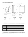
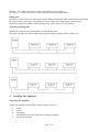
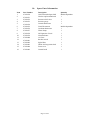
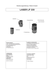
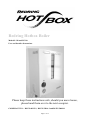
Redring Hotbox Boiler
Models L318 and LP330
User and Installer Instructions
Please keep these instructions safe, should you move house,
please hand them over to the next occupier.
COMPLIANT TO : BS EN 60335-2, BS EN 55014-2 and BS EN 50081-1
Page 1 of 13
Redring Hotbox Boiler
THE HALOGEN BOILER, L318, LP330
HALOGEN POWERED WALLMOUNTED BOILER
USER&INSTALLERS INSTRUCTIONS
PLEASE KEEP THESE INSTRUCTIONS SAFE. SHOULD YOU MOVE HOUSE, PLEASE
HAND THEM OVER TO THE NEXT OCCUPIER.
1.
Introduction
The Halogen Boiler is a wall-mounted appliance, suitable for installation onto small sealed heating systems.
It incorporates all the components for sealed system requirements, these include, pressure gauge, pressure
relief valve, expansion vessel, circulating pump and manual reset overheat thermostat. A manual air vent is
also located on the appliance. There are two controls on the appliance, one adjusts the water flow
temperature, and the other is an on/off switch. A 2 m long electrical flex with integral plug enables the
appliance to be connected into a standard 13A ring main socket or via the 24 hour plug in timer supplied.
2.
Technical Specification
Performance Data
Electrical Input
Heat Output to Water
Heat Output Convection
kW
kW
kW
L318
6 x 0.300
1.71
0.09
LP330
10 x 0.300
2.85
0.15
General Specification
Product Catalogue Number
Halogen Bulb Heat Source
Electricity Supply
External Fuse (supplied plug)
Water Connections Flow
Water Connections Return
Expansion Vessel Charge
Minimum operating flow temp.
Maximum operating flow temp.
L318
29-394601
6 x 300W
220 - 240V ~ 50 Hz
10A
22 mm Copper
22 mm Copper
0.5 bar
20°C
70°C
Page 2 of 13
LP330
29-394602
10 x 300W
220 - 240V ~ 50 Hz
13A
22 mm Copper
22 mm Copper
0.5 bar
20°C
70°C
Overall Dimensions & Minimum Clearances
Clearances
Side
Top
Bottom
Front
3.
mm
mm
mm
mm
Operational
5
200
200
5
Maintenance
5
200
200
500
Installation Requirements
Statutory Requirements
The installation should also be in accordance with the relevant recommendations in the current editions of
the following British Standards:
BS 7074: Pt 1
BS 5449
BS 7671
BS 4814
BS 6798
BS 6759: Pt 1
BS 1362
BS 5376
Expansion vessels and ancillary equipment for sealed water systems
Forced circulation hot water systems for domestic premises
Requirements for Electrical Installations. IEE Wiring Regulations.
Expansion Vessels using an internal diaphragm for sealed hot water systems.
Installation of gas fired boilers of rated input not exceeding 70 kW Net.
Safety valves
General purpose fuse links for domestic & similar purposes. (Primarily for use in
plugs).
Code of Practice for selection & installation of gas space heating
Boiler Location
The boiler is not suitable for external installation . The position selected must be within the building unless
protected by a suitable enclosure. There must be adequate space for installation, servicing and operation of
the boiler as well as adequate air circulation.
Page 3 of 13
If the boiler is to be placed in a cupboard this cupboard should not be used as a storage cupboard. Ventilation
should be provided as detailed below.
Ventilation
This boiler does not require a purpose provided air ventilation in the room, however it does require room air
to circulate through the boiler to ensure the convection heat output performance is maintained.
If the boiler is installed in an enclosure or small cupboard, there must be an equivalent ventilation free area
in the enclosure or small cupboard to that of the boiler.
Upper Ventilation Free Area
Lower Ventilation Free Area
These should be the same or larger than in the
appliance case mm2
As above
Electrical Supply
This appliance must be earthed
The appliance is supplied with a 2 m electrical flex with integral fused plug, which requires a standard 220 240V ~ 50Hz supply via a normal ring main socket. If required, the plug connection can be made via the 24
hour plug in timer supplied.
All fuses must be ASTA approved to BS 1362
In the event of an electrical fault after installation of the boiler, preliminary electrical system checks must be
carried out. i.e. earth continuity, short circuit, polarity and resistance to earth.
Central Heating Systems
This boiler is designed specifically for use in small, pressuris ed, sealed system installations. The installation
must comply with BS 6798.
Safety Valve – The safety valve, which is pre-set at a maximum of 3 bar is an integral part of the boiler and
cannot be adjusted. Its relief outlet must be piped to a suitable o utside position.
Pressure Gauge
This indicates the system fill pressure. It will show a higher pressure when the system is hot.
Circulating Pump
The circulating pump is located inside the boiler case. Its performance is suitable for all systems to which
the boiler should be connected.
Expansion Vessel
The expansion vessel, which is located inside the boiler case, has a capacity of 2.0 L, with a pre -charge of
0.5 bar.
The maximum heating system water content using this integral expansion vessel is 2 4.0 L. This is with a
cold fill of 0.5 bar.
Should the system volume be in excess of that specified, a second expansion vessel must be connected to the
heating system. BS 5449 gives further guidance for expansion vessel sizing.
Vessel Charge and Initial System Fill Pressure
For Expansion Vessel Capacity
(Multiply the system Volume by)
Total system water capacity using the integral
2.0 L expansion vessel
Page 4 of 13
Bar
Litres
0.5
1.0
1.5
0.0833
0.109
0.156
25.0
18.4
12.8
Example: 30L system total capacity requires an expansion vessel capacity of
30 x 0.0833 = 2.5 litres with a 0.5 bar vessel charge and system cold fill pressure.
Filling Point
The heating system must be provided with a suitable filling mechanism to both complete the initia l fill and
top up the system if necessary. The filling device must comply with Water Supply (water fittings)
Regulations and the local Water Authority Regulations. Refer to BS 5376: for guidance.
Typical System Diagrams
Thermostatic radiator valves should NOT be used with this boiler.
The boiler is designed for small sealed heating systems usually operating within a single room.
4.
Installing The Appliance
Unpacking The Appliance
Unpack the appliance and check the contents with the list below.
1
4
4
1
1
Boiler
Screws
Rawlplugs
Installation & Servicing Instructions including Guarantee
Plug in 24 hour timer
Page 5 of 13
Location
Before installing the boiler check that the chosen location is suitable, ensuring a dequate clearance is
available for both installation and servicing. The appliance must be mounted on a flat vertical wall.
Prepare the Appliance
Remove the front panel by unscrewing the two screws at the bottom of the case. Rotating the case forwards
at the bottom 10 mm and lifting it off in an upward direction.
Preparing the Wall
Using the diagrams earlier in these instructions, or the appliance as a template, mark four positions on the
wall were the fixing screws will fit. Ensure the appropriate clearances for the boiler have been established.
The wall should be drilled with a 4 mm masonry drill after ensuring there are no electric cables within the
hidden fabric of the building.
Insert the rawl plugs followed by the two upper screws. These should be inserted to within 2 mm of the wall.
Mark a suitable position for the pressure relief discharge pipe ensuring a suitable position outside. Drill
through the wall with a 16 mm minimum diameter masonry drill to accept a 15 mm copper pipe. This is f or
the pressure relief discharge.
Mounting the Boiler
Locate the boiler onto the two screws. Fit the two lower screws and tighten all 4 screws to secure the
appliance in position.
Water Connections
Refer to Section 3 for detailed information.
The boiler flow and return service valves should be connected directly to the heating system. The flow is on
the right hand side, the return being on the left hand side. Each is marked accordingly.
A suitable method of filling the system should be fitted to th e system. The method used for filling the system
must comply with the local Water Authority Regulations. A drain cock should be fitted to the lowest point of
the system. The pressure relief outlet should be connected to a suitable outside position.
Electrical Connections
The appliance is supplied with a 2 m length of 3-cone cable with a normal plug pre-wired. This can be
plugged directly into a suitable 220 - 240V ~ 50 Hz, ring main 13 A wall socket.
If required, the plug in timer supplied can be added to control the appliance on / off periods.
5.
Commissioning & Testing
The front cover to the boiler should now be replaced.
Fill and flush the system with all the valves open. Refill the system and check for soundness. Vent the
system, including each radiator and the boiler. At this point the heating system should have been thoroughly
flushed with cold water, filled and vented to a pressure of 0.5 bar cold and be free from leaks.
Note: With the appliance switched on and the thermostat set at the lowest (off) position the pump will
circulate water around the system but the halogen bulbs are prevented from operating.
Plug in the boiler and switch on the electrical supply. Switch the appliance switch on and turn the control
knob to high. The pump should start to circulate water around the system and the Halogen bulbs will start to
heat the water. A thermostat within the boiler will control the temperature of the water as set on the control
knob.
Page 6 of 13
Allow the heating system to reach operating temperature and then examine for water leaks.
Turn off the boiler and drain whilst still hot.
Refill and vent the heating system ensuring all air is cleared from the system and the cold fill pressure is set
at the design pressure.
The pressure gauge should be at 0.5 bar.
Set the indicator on the pressure gauge to co-inside with this initial cold fill pressure.
Allow the appliance to operate to its maximum temperature to ensure correct operation of the boiler controls.
Check the maximum pressure of the system when at this maximum temperature and ensure no water has
been expelled from the pressure relief outlet.
Hand the instructions to the user for retention and instruct in the efficient and safe operation of the boiler.
Advise the user of the precautions necessary to prevent damage to the heating system and building in the
event of the system remaining inoperative during frost conditions.
6.
Operation and User notes
During normal operation of the boiler and its heating system there should only be a need to switch the boiler
on and off as required. The 24 hour plug in timer provided can be used to provide this function.
The operation pressure will rise and fall in line with temperature increase and decrease of the heating system
water temperature. This is normal operation. However should the pressure fall below that set on the pressure
gauge (0.5 bar) this is an indication there is either a leak in the heating system or the expansion vessel is too
small for the heating system volume. You should consult your Service Engineer in order to correct the fault.
To shut off the boiler for short periods turn the thermostat switch to the off position. This will leave the
pump circulating water around the heating system.
To shut off the boiler for longer periods turn the boiler switch to the off position, this will switch the pump
and the heating bulbs off, allowing the heating system to cool to ambient temperature.
To shut off the boiler for extended periods whilst the house may be unoccupied when there is a possibility of
frost turn the boiler switch to the off position and electrically isolate the boiler. Drain the heating system
down. If a suitable anti freeze has been introduced into the heating system it may not be necessary to drain
down.
WARNING:- Do not switch on the appliance if there is a possibility that the water in the heater is frozen.
Your installer will advise you about draining the system
7.
Routine Servicing and Replacement of Parts
As this is an electrical boiler there is no need for regular preventative maintenance, however at periodic
intervals each of the bulbs should be checked for operation.
Before commencing any service operation, ISOLATE the mains electrical supply to the boiler by switching
off at the mains plug and removing the plug from the socket. Remove the boiler front cover by first
unscrewing the two screws at the base of the boiler and rotating and lifting the cover off the boiler.
After completing any service operation, refit the boiler cover and re commission the boiler as detailed in
Section 5.
Should the supply cord become damaged it must be replaced by a special cord assembly available from the
manufacturer or its service agent.
Page 7 of 13
Replacing a bulb
•
•
•
Remove the lid from the bulb box, remove the faulty bulb and replace with a new bulb. Do not touch the
bulb with bare fingers, as this will reduce the life of the bulb. Use clean tissue paper or similar to hold
the bulb.
Check that the bulb is seated correctly on the contacts.
Replace the top of the bulb box, locating it onto the pins provided.
Replacing a bulb temperature limit thermostat
•
•
•
•
The bulb temperature limit thermostat can only be replaced as a complete lamp holder unit as follows.
Disconnect the power supply from the lamp holder at one side of the holder and the limit thermostat and
withdraw the lamp holder from the lamp box.
Replace with a new lamp holder assembly, locating it onto the pins provided.
Ensure the wires are connected correctly.
Replacing the control thermostat
•
•
•
•
•
•
Pull off the electrical connections from the thermostat body, noting the termination positions on the
body.
Pull off the control knob from the spindle.
Remove the two fixing screws and lower the thermostat.
Withdraw the thermostat phial from the pocket located on the side of the boiler flow pipe.
Withdraw the thermostat and capillary from the boiler.
Replace in reverse order taking care to route the capillary away from any electrical connections and that
the electrical connections to the thermostat body are arran ged as the original.
Replacing the overheat thermostat
•
•
•
•
Pull off the electrical connectors from the thermostat body.
Remove the locknut securing the thermostat body to the lower casing panel and lift the thermostat from
its mounting position.
Remove the phial from the pocket on the side of the boiler flow pipe and withdraw the thermostat and
capillary from the boiler.
Replace in reverse order taking care to route the capillary away from any electrical connections.
Replacing the circulating pump
•
•
•
•
•
Isolate the pump using the valves at each side of the pump or the appliance isolation valves on the flow
and return connections to the boiler.
Disconnect the plug and socket connection in the pump electrical supply.
Remove the pump from the pipe work.
Refit a replacement pump in reverse order ensuring it is pumping in the correct direction and the
electrical wiring is correct.
Open the isolation valves, ensure the system cold fill pressure is correct, there are no water leaks and the
system is correctly vented of all air.
Page 8 of 13
Replacing the expansion vessel
•
•
•
•
Isolate the boiler using the appliance isolation valves on the flow and return connections to the boiler.
Remove the expansion vessel from the pipe work.
Refit a replacement expansion vessel in reverse order using a recognised method of sealing the threaded
joint.
Open the isolation valves, ensure the system cold fill pressure is correct, there are no water leaks and the
system is correctly vented of all air.
Replacing the pressure relief valve
•
•
•
•
•
•
Isolate the boiler using the appliance isolation valves on the flow and return connections to the boiler.
Disconnect the pressure gauge tapping from the top of the relief valve.
Release the discharge pipe from the valve.
Remove the pressure relief valve from the pipe work.
Refit a replacement pressure relief valve in reverse order using a recognised method of sealing the
threaded joint.
Open the isolation valves, ensure the system cold fill pressure is correct, there are no water leaks and the
system is correctly vented of all air.
Replacing the pressure gauge
•
•
•
•
•
Isolate the boiler using the appliance isolation valves on the flow and return connections to the boiler.
Remove the pressure gauge from the pipe work as described above.
Depress the locating tabs on the gauge body and push the body through the mounting bracket.
Refit a replacement pressure gauge in reverse order ensuring the seal at the pressure relief valve is
sound.
Open the isolation valves, ensure the system cold fill pressure is correct, there are no wa ter leaks and the
system is correctly vented of all air.
8.
Fault Diagnosis
If a fault develops, or is suspected, call your Service Engineer as soon as possible
Go through the following checklist before you make contact
•
•
•
•
•
•
•
•
•
•
•
Is the electricity supply on?
Are the lamps lit?
Has the limit thermostat tripped?
Are the boiler isolation valves open?
Are the pump isolation valves open?
Is the boiler switch on (giving a red “Power ON” light)?
Is the heating system water pressure correct?
Is the boiler temperature control set correctly?
Is the time clock (if fitted) calling for central heating?
Is the room thermostat (if fitted) set high enough?
Are the radiator valves open?
Page 9 of 13
Fault Finding Chart
If the radiators do not get hot or do not reach the boiler flow operating temperature follow the guide below to
establish the possible cause.
Page 10 of 13
9.
Wiring Diagram
Page 11 of 13
10.
Item
1
2
3
4
5
6
7
8
9
10
11
12
13
14
15
16
Part Number
97392070.
97392071.
97392072.
97392073.
97392074.
97392075.
97392076.
97392077.
97392078.
97392079.
97392080.
97392081.
97392082.
97392083.
97392084.
97392085.
Spare Parts Information
Description
300 W linear halogen bulb
Hot box replacement head
Pressure relief valve
Pressure gauge
Control thermostat
Limit Thermostat
Overheat thermostat
Water Pump
2lt Expansion Vessel
Neon Indicator
Air Vent
Rocker switch
Sight Glass
White 2m long mains lead
Front cover
Control knob
Page 12 of 13
Quantity
Model dependant
1
1
1
1
Model dependant
1
1
1
1
1
1
1
1
1
1
GUARANTEE
Terms and Conditions for UK & ROI (outside UK & ROI contact your local distributor)
We, Applied Energy Products Limited, guarantee this product for domestic use only, for the period of 12
months from the date of purchase.
Within the guarantee period we will resolve, free of charge, any manufacturing defects in the product resulting
from faulty workmanship or material on condition that:a)
The appliance has been correctly installed in accordance with our instructions and is being used on the
supply circuit or voltage printed on the rating plate,
b)
The appliance has been used in accordance with these instructions and has not been tampered with or
otherwise subject to misuse, neglect or accident.
c)
The appliance has not been taken apart, modified or repaired except by a person authorised by us.
d)
Evidence of the date of purchase in the form of an invoice or receipt will be required in order to qualify for
an in-guarantee repair,
e)
For the service work to be undertaken free of charge, the work must be only undertaken by
Applied Energy Products Limited, or our approved agents.
f)
Service under guarantee has no effect on the expiry date. The guarantee on any exchanged parts or product
ends when the original guarantee period ends.
EXCLUSIONS
This guarantee DOES NOT cover damage or defects arising from poor or incorrect installation, improper use or lack
of maintenance, including build-up of limescale. It is the responsibility of the installer to check that the installation
parameters meet the requirements of the product, and any relevant regulations.
If we are called out to a fault, which is subsequently identified as being an installation fault, we will make a charge. It is
important that the routine checks are completed before calling us out, as many issues can be simply diagnosed and
resolved.
We make no guarantees as to response times for repairs. We will endeavour to achieve the most timely response
possible but while we indicate an average response time, this should not be taken as a guarantee.
The guarantee applies to a repair or replacement (at our discretion) of the product subject to the conditions above, and
DOES NOT cover compensation for the loss of the product or consequential loss of any kind.
The guarantee DOES NOT apply to the repair or replacement of halogen lamp heaters, pressure relief devices,
accessories, isolating switches, electrical cable, fuses and/or circuit breakers.
This guarantee does not affect your statutory rights.
Full details of terms and conditions are available on request from :-
APPLIED ENERGY PRODUCTS LIMITED
MORLEY WAY, PETERBOROUGH, PE2 9JJ
TEL : 01733 456789 / FAX : 01733 310606
Website : www.applied-energy.com
Page 13 of 13