1
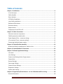
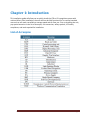
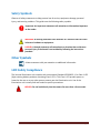
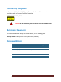
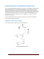
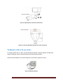
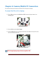
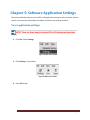
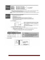
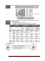
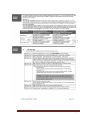
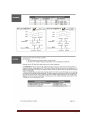
C50 & C6 Installation Manual Document Information Version 1.1 Release date April, 2011 Table of Contents Chapter 1: Introduction ......................................................................................................... 4 List of Acronyms .......................................................................................................................... 4 Safety Symbols ............................................................................................................................ 5 Other Symbols ............................................................................................................................. 5 LED Safety Compliance ................................................................................................................ 5 Laser Safety compliance .............................................................................................................. 6 Referenced Documents ............................................................................................................... 6 Document History ....................................................................................................................... 6 Required tools ............................................................................................................................. 7 Components of the C50 or C6 ..................................................................................................... 7 Chapter 2: Cables Connections ............................................................................................... 8 Ethernet connector components ................................................................................................ 9 Flexible protective conduit cable .............................................................................................. 12 Power Supply (4 Pins – connector wiring) ................................................................................ 12 I/O connector (7 pins- connector wiring).................................................................................. 13 Connecting (optional) power supply ......................................................................................... 15 Chapter 3: Camera/Bracket Assembly .................................................................................. 16 Bracket and Camera Installation on a Wall or Pole .................................................................. 19 Chapter 4: Camera/Mobile PC Connection ........................................................................... 22 Chapter 5: Software Application Settings ............................................................................. 24 Lane level................................................................................................................................... 25 Lane Settings ............................................................................................................................. 25 Camera Level-Setting Dual or Single camera ............................................................................ 27 Capture Sets .............................................................................................................................. 30 General Settings ........................................................................................................................ 31 Save Image Settings................................................................................................................... 33 Communication Settings ........................................................................................................... 34 Diagnostics Settings .................................................................................................................. 35 System Alert Settings ................................................................................................................ 38 Chapter 6: Single Camera/Dual Cameras – on site Calibration and Fine-tuning ..................... 40 General Information .................................................................................................................. 40 C50 and C6 Installation Manual Page 2 Cameras calibration .................................................................................................................. 41 Calibrating first camera- B/W Camera ...................................................................................... 42 Calibrating second camera- Color Camera................................................................................ 43 Live Video Mode........................................................................................................................ 45 Recognition Camera Setting (Shutter and Gain) ....................................................................... 46 Chapter 7: VMD Software Trigger - on site calibration & fine-tuning..................................... 47 Defining the Area of Interest..................................................................................................... 47 Chapter 8: Hardware Trigger – Laser Trigger......................................................................... 49 Laser Trigger configuration ....................................................................................................... 49 Laser installation ....................................................................................................................... 50 Laser Setup ................................................................................................................................ 50 Laser configuration.................................................................................................................... 51 Chapter 9: Hardware Trigger - Ground Loops Trigger configuration ...................................... 55 Preparations .............................................................................................................................. 55 Installation Location Considerations ......................................................................................... 55 Chapter 10: QC- calibration check list form .......................................................................... 60 Chapter 11: Support and More Information ......................................................................... 64 Contact Information .................................................................................................................. 64 Appendix A: IP configuration ............................................................................................... 65 LAN connection: ........................................................................................................................ 65 Configure lane ID: ...................................................................................................................... 65 Explanation: ............................................................................................................................... 65 Appendix B: Configuring the laser trigger to MANUAL .......................................................... 66 Appendix C: Ground Loop, Specifications & user guides ....................................................... 68 SMA Datasheet .......................................................................................................................... 68 Matrix Ground Loop User Guide ............................................................................................... 69 C50 and C6 Installation Manual Page 3 Chapter 1: Introduction This installation guide will allow you to quickly install the C50 or C6 recognition system with minimal effort. After installation, the unit will now be fully functional for its various intended uses such as toll roads, surveillance, average speed and car flow, etc. Prior to installing the unit, pay special attention to the list of acronyms, unit conversion, safety symbols, LED safety compliance, and tools required for installation. List of Acronyms C50 and C6 Installation Manual Page 4 Safety Symbols Observe all safety statements to help prevent loss of service, equipment damage, personal injury, and security problems. This guide uses the following safety symbols: Important: An Important statement calls attention to information important to the reader. WARNING: A warning statement calls attention to a situation that can result in harm to hardware or equipment. HAZARD: A hazard statement calls attention to a situation that could cause personal injury if the hazard is not avoided by following the instructions provided. Other Symbols A Note statement calls your attention to additional information. LED Safety Compliance The internal illumination unit complies with International Standard IEC 60825–1, for Class 1 LED (light emitting diodes) products containing Class 1 LED’s. This Class 1 LED product poses no hazard to the user or to any other person present near the illumination unit. Use of the illumination unit is totally safe and needs no specific precautions. HAZARD: Do not look directly into the camera for more than a few seconds. C50 and C6 Installation Manual Page 5 Laser Safety compliance In Operational Mode: The FLM-10-T is classified as a Class 1 eye safe laser product in compliance with the European Eye Safety Regulation: CENELEC EN60825-1 (2001) HAZARD: Do not look directly into the Laser for more than a few seconds. Referenced Documents For more information on SeeWay and related systems, see the following guide. SeeWay Utilities – Description of utilities (iWD, iCalJAI, iCleaner) Document History Ver # Version Date Author 1.0 01/01/2011 Doron A First release All 1.1 04/07/2011 Yossi Rosoff Updated entire manual All C50 and C6 Installation Manual Comment Sections Affected Page 6 Required tools Allen wrench (5.30mm) Allen wrench (8mm) Phillips head screwdriver (4.95mm) Components of the C50 or C6 C50 or C6 -IR high speed system. Power supply is 24 VDC (optional. Available for purchase at Hi-Tech Solutions). Connector 6+PE B-0218-00-07 binder. Connector 3+PE B-0210-00-04 binder. Bracket 3 axis anodized gold set. Ethernet connector px 0834/B. Flexible protective conduit cable (available for purchase outside of Hi-Tech Solutions). Power supply cable (optional, available for purchase at Hi-Tech Solutions). Ethernet cable (available for purchase outside of Hi-Tech Solutions). _______________________________________________________________ NOTE: Hi-Tech Solutions recommends an Ethernet cable of 5E or 6 for a distance up to 100 meters. C50 and C6 Installation Manual Page 7 Chapter 2: Cables Connections This chapter will show you the step-by-step procedure on how to assemble the camera head cables and connectors. The general gantry wiring design is shown in the following figure: Figure 1: General gantry wiring design Cable types: For the power cable use cable that contain 2 wires of 14 AWG, For the 7 Wires cable use cable that contain 7 wires of 22 AWG. For the Ethernet Cable use Category 5e cable. The ends of the cables are connected to the C50 or C6 camera head by the following connectors: Ethernet connector PX0834/A and PX0834/B Ethernet Buccaneer. Power Supply "Binder Connector" number B-0210-00-04. I/O connector "Binder Connector" number B-0210-00-04. C50 and C6 Installation Manual Page 8 Ethernet connector components 1. Locking ring 2. Locking ring tool 3. Carrier molding 4. RJ45 plug 5. Load bar 6. Connector body 7. Gland 8. Gland cage 9. Gland nut 10. Cable Figure 2: Ethernet connector components To assemble Ethernet connector: 1. Thread the gland nut, gland cage, and connector body on to the cable. Figure 3: Gland nut, gland cage and connector body C50 and C6 Installation Manual Page 9 2. Remove the cable jacket carefully taking care not to damage the braid and foil. Fold back the braid and foil over the cable jacket. Figure 4: Cable jacket 3. Un-twist the conductors and feed through the appropriate hole in the load bar, according to the loading standard required. Push the loading bar fully home on to cable. Trim conductors to extend 8.64 mm (0.34”) out of the front of the load bar. Figure 5: Load bars and cable jacket conductors 4. Push the load bar and cable fully home into the RJ45, ensuring the braid and foil are in contact with the metal shell. Crimp the RJ45 with an appropriate crimp tool and die set. Trim back braid and foil flush with the rear of the RJ45 body. Figure 6: RJ45 and load bar cable C50 and C6 Installation Manual Page 10 5. Crop the latching clip on the RJ45 making sure that it’s completely removed. Figure 7: RJ45 plug 6. Push the RJ45 into the carrier molding until it latches. Figure 8: RJ45 plug and carrier molding 7. Pull up the connector body and locate the carrier. The carrier sits into a ‘D’ shaped aperture in the connector body, make sure it’s sealed correctly. Locate the locking ring tool and tighten ring to retain insert, using the assembly tool (locking ring tool) provided. Figure 9: Locking ring and connector body 8. Slide gland, gland cage and gland nut up to the body moulding, and then tighten to torque of 1.5-2.0lb/ins, 13-18 Nm. Figure 10: Gland, gland cage and gland nut C50 and C6 Installation Manual Page 11 Flexible protective conduit cable _______________________________________________________________ NOTE: It is recommended that you purchase the protective conduit cable prior to the next installation procedure. Figure 11: Flexible protective Conduit cable Power Supply (4 Pins – connector wiring) The following table shows the power supply connections from the main power supply cable to the imaging unit. Table 1: Default power supply image/unit connection _______________________________________________________ NOTE: It is recommended to use a ferrule 1.8mm for each wire. Figure 12: Ferrule C50 and C6 Installation Manual Page 12 I/O connector (7 pins- connector wiring) The following table shows the default wiring of the inputs (pins 1-6) and outputs to the laser/Loop detector cable wires. Table 2: Default laser connector connections C50 and C6 Installation Manual Page 13 Figure 13: Control connector wiring ________________________________________________________________ NOTE: Additional RS232 cable is connected internally, to control the laser via an external kit. C50 and C6 Installation Manual Page 14 Connecting (optional) power supply Follow the steps to connect the 3+PE cat number B-0210-00-04 binder to the optional power supply to the C50 or C6 camera. 1. Connect the black wire to the negative (-) and the red wire to the positive (+). Figure 14: Rear of optional power supply 2. Connect the 3+PE connector cable to the rear of the camera. 6+P E 3+PE Figure 15: Rear view of C50 camera ____________________________________________________ NOTE: 6 +PE connector is for optional laser or loop control. C50 and C6 Installation Manual Page 15 Chapter 3: Camera/Bracket Assembly This chapter will show you the easy to follow step-by step procedure to install the bracket to the camera. _______________________________________________________ NOTE: For Gantry Design, the following bracket is being used: Figure 16: Dimensions of anodized bracket Figure 17: Assembled anodized bracket ____________________________________________________ NOTE: Three-piece anodized bracket is factory assembled. C50 and C6 Installation Manual Page 16 To install bracket and camera assembly: 1. Unscrew and remove the upper bracket. Figure 18: Upper bracket 2. Attach upper bracket to bottom of the camera and tighten screws. Figure 19: Upper bracket attached to bottom of camera C50 and C6 Installation Manual Page 17 3. Re-attach upper and lower bracket and tighten screws. Figure 20: Upper and lower bracket attachment 4. Attach bracket to your specified gantry. C50 and C6 Installation Manual Page 18 Bracket and Camera Installation on a Wall or Pole The recommended angle between the C50 or C6 and the car is 15-16 degrees. The angle should not exceed 30 degrees. The camera should face downwards in order to minimize the sun’s effect. Since most plates are mounted at a height of 0.20 to 1.25 meters, the recommended height for the C50 or C6 unit is between 1 to 1.5 meters. The maximum height at which the C50 or C6 should be installed is 3 meters. In this case, the camera should be positioned in such a way that the center of the vertical field of view is the trigger area. For higher installations, consult Hi-Tech Solutions. You can mount the C50 or C6 unit on a wall, or install it on a pole or tripod. The following sections provide installation instructions. To Mount a C50 or C6 on a Wall: Follow the instructions as indicated in the following illustrations: Figure 21: Mounting C50 or C6 on a wall C50 and C6 Installation Manual Page 19 Figure 22: Adjusting C50 or C6 Position and Direction Figure 23: Location of Wall Mounting Holes for a C50 or C6 Camera To Mount a C50 or C6 on a Pole: To mount a C50 or C6 on a pole, use the BR-20 pole adapter. The pole adaptor includes two straps of different sizes to accommodate various pole measurements. Attach the pole adapter to the pole using one of the straps. Tighten the strap. Figure 24: BR-20 Pole Adapter C50 and C6 Installation Manual Page 20 Connect the bracket base of the C50 or C6 to the pole adapter board. Use the three screws and nuts provided in the pole adapter kit. Figure 25: Screw Locations in the Pole Adapter C50 and C6 Installation Manual Page 21 Chapter 4: Camera/Mobile PC Connection This section will show you the steps to install the C50 or C6 camera to a laptop. To connect the C50 or C6 to a laptop: 1. Plug in LAN connection on the left side and 3+PE connector wiring as shown in the following figure. Figure 26: Rear of C50 camera 2. Connect LAN connection wire to laptop. 3. Confirm orange lighting, by removing the two Allen screws (M5) at the top of the cover and remove the top cover plate. Figure 27: Interior of C50 camera __________________________________________________ NOTE: Orange lighting in figure 20 above signifies 1 GB. C50 and C6 Installation Manual Page 22 4. Connect to remote desktop. From start Select Program Select accessories Select remote desktop 5. Enter default IP number 192.168.0.50. Click connect. 6. Enter username (administrator) and password (hts). Click OK. C50 and C6 Installation Manual Page 23 Chapter 5: Software Application Settings This section describes how to set the C50 or C6 application settings in order to obtain the best results. It assumes that all software, hardware and drivers are already installed. To set application settings: _______________________________________________________________ NOTE: There are three ways to access C50 or C6 settings as described below. 1. Click File. Select Settings. Figure 28: Main menu toolbar 2. Click Settings in the toolbar. Figure 29: Main menu toolbar 3. Press F8 hot key. C50 and C6 Installation Manual Page 24 4. The Settings dialog box appears: Figure 30: Settings dialog box _______________________________________________________________ NOTE: C50 or C6 application default settings fit most of the installation cases. Lane level The number of lanes is always 1, since the C50 or C6 is a single lane system. Each of the parameters of the lane can be configured according to the installation requirements. Lane Settings The lane settings display is seen in the following page as Figure 23. It configures the lane with general parameters, and additional information is defined at a lower (camera level) setting. C50 and C6 Installation Manual Page 25 Figure 31: Lane settings dialog box The window’s components are described in table 3 below: Parameter Description Trigger Trigger type Capture on sensor The type of trigger that initiates the recognition event. Hardware – Laser device that detects vehicle presence that is connected to the camera. The laser is connected only to one camera, so the user must select the correct camera. Software VMD – Implemented as part of this application. Triggers recognition when a vehicle enters a specified area of view. When trigger type is “Hardware”, this option controls the way input from the hardware trigger is interpreted. Default: Rising. Sensor is Normally Open This option must reflect the hardware loop detector setting. Please refer to the loop detector’s user manual (for technicians). Sensor Pin Default: Normally Open. Unused – disabled. C50 and C6 Installation Manual Page 26 Sensor Delay Defines the time in milliseconds from the point that the vehicle enters the trigger point and until the application receives the trigger. According to this value, the application will use images captured X milliseconds before receiving the trigger. This entry is critical for fast moving vehicles in a case of a slow detector. Range: 0 – 200 ms. Default: is 0, which is good for a fast detector. Illumination Turn on by trigger Unused – disabled. Last Name The lane name editing is possible by editing lane label on the left tree control. It is similar to re-naming in Windows Explorer: make focus on the lane label by mouse click; by second click enter editing mode and change the label. The lane name is used only as a title for the C50 or C6 display. Adds a camera to the application. Minimum one and maximum two cameras are allowed. Removes a camera from the application. Minimum one and maximum two cameras are allowed. You cannot remove both cameras. Add Camera Remove Camera Table 3: Lane settings parameters Camera Level-Setting Dual or Single camera These settings determine the configuration of the camera(s) in the system. Each C50 or C6 can have 1 or 2 cameras, and each is configured separately. The following figure shows a sample display, and its components are detailed in the following page. C50 and C6 Installation Manual Page 27 Figure 32: Recognition camera settings Parameter Description Mac Address Associates the camera to the lane by its MAC address, which is a unique identifier for the device. Changing this settings item must be done in a cautious way. There is no option to connect the same device to different lanes. The application will issue a warning when you assign the same MAC addresses for different lanes on the same PC, but it cannot determine if you assign the same MAC addresses for different lanes on different PC’s. Default: This value is read from the device and should normally be left at its original value. General LSB Pin Prefix Associates the terminal block pin to the camera illumination control LSB (least significant bit). The MSB (most significant bit) is connected to the next pin. Defaults: 3 – 7. Defines the prefix for the image file name. Default: “xy” (where x is the lane number and y is the camera number) – e.g. “11” for lane number 1 and camera number 1. C50 and C6 Installation Manual Page 28 Overview Camera If checked, functioning as overview camera. Default: Not checked. Area of Interest Automatic Image Quality Min. Gain Defines the area in the image that will be used for motion detection, if this feature is used. This only displays the area coordinates. To set this area, use Live Video window. Default: Full frame. Left – 0, Right – 1376, Top – 0, Bottom – 515. When enabled, the auto – gain function is activated. This function maintains the brightness of the image to a desired brightness value, regardless of the changing environment, thus increasing the image quality at bad light conditions. The calculation is done on basis of a moving average of the last 10 vehicles. It will therefore adapt the camera signal gain to the changing environment light conditions. The mechanism repeats itself every 30 seconds until the desired brightness is reached or it meets one of the limits (minimum and maximum gain). If this option is enabled, the manual gain changing is disabled. Thus, the fields cannot be changed in Live – video and capture – set pages. Default: Disabled. Minimal allowed gain value, the system can set in the auto-gain function. Default: 0. Max. Gain Maximum allowed gain value system can set in the auto-gain function. Desired Brightness Threshold Add Capture Set Remove Capture Set Default: 254. The auto-gain function target value. It defines the desired image brightness, where 0 is totally black and 255 is totally white. Default: 150. Allowed threshold for the desired brightness before system changes gain set direction. This value is used to prevent the auto-gain function to bounce up and down around the proper value. Default: 10 Adds a capture set for this camera. Removes a capture set for this camera. Table 4: Recognition camera setting parameters C50 and C6 Installation Manual Page 29 Capture Sets For each capture set that is defined, the user can configure its settings using the following window which is opened while selecting the item under the camera settings. Figure 33: Capture set definition window C50 and C6 Installation Manual Page 30 Table 5: Capture set definitions parameters General Settings Figure 34: General settings C50 and C6 Installation Manual Page 31 Table 6: General settings parameters C50 and C6 Installation Manual Page 32 Save Image Settings Figure 35: Save images C50 and C6 Installation Manual Page 33 Table 7: Save images parameters Communication Settings Figure 36: Communication settings C50 and C6 Installation Manual Page 34 Table 8: Communication settings parameters Diagnostics Settings Figure 37: Diagnostics setting box C50 and C6 Installation Manual Page 35 Parameter Description Performance Alerts Error threshold Defines the threshold to set an error alert in case of low recognition. The error is recorded in the application Event log and will show as a “red” state in the SeeMonitor utility. When the recognition rate increases, the application will write an information event that cancels the error. Range: 0 – 100 (0 will not generate errors). Warning threshold Default: 75 Defines the threshold to set a warning alert in case of low recognition. The value is lane specific, and is calculated as the percent of recognized events within the last number of defined “minimum events”. For example, 21 recognitions out of 25 events yield 84% recognition accuracy. The warning is recorded in the application Event Log and will show as a “yellow” state in the SeeMonitor utility. When the recognition rate increases, the application will write an information event that cancels the warning. Range: 0 – 100 (0 will not generate any warnings. Minimum events Default: 85 Sets the size of the performance group. This value is used to calculate the recognition rate for the warning and error alerts. Default: 25 Process alerts C50 and C6 Installation Manual Page 36 Memory warn Memory Error Sets the value of C50 or C6 memory usage level from which the system writes a Warning message to the system’s Events Log. If the C50 or C6 memory usage is back to normal range, the system writes an Information message. Default: 600 Sets the value of C50 or C6 memory usage level from which the system writes an Error message to the system’s Events Log. If the C50 or C6 memory usage is back to normal range, the system writes an Information message. Default: 900 Monitor Check system and process performance every X Minutes Sets the time’s frequency of the diagnostic checks. Default: 1 Minute Table 9: Diagnostics setting parameters C50 and C6 Installation Manual Page 37 System Alert Settings Figure 38: Systems alert settings dialog box C50 and C6 Installation Manual Page 38 Table 10: Systems alert settings parameters C50 and C6 Installation Manual Page 39 Chapter 6: Single Camera/Dual Cameras – on site Calibration and Fine-tuning General Information Before calibration on site, please note: Lane closure – For cameras fine tuning, the lane should be closed. Make all preparations for the lane to be closed such as road blocks and flashing lights. Safety preparations must be taken to insure the workers safety, such as safety shoes and reflecting vest. This chapter will describe the arrangement for calibrating C50 or C6 imaging unit cameras on sites. ________________________________________________________________ NOTE: This setup is for the cameras and laser; it should be tested both at night and daytime. __________________________________________________________________ NOTE: If the installation is for Dual cameras, the B/W camera should be selected as the first camera (camera 11) and the second camera will be the color camera (camera 12). C50 and C6 Installation Manual Page 40 Cameras calibration The following diagram presents a typical installation on gantry. The C50 or C6 imaging unit will be installed as per the following top view diagram. Figure 39: Imaging unit location design (lane coverage) _____________________________________________________________ NOTE: HTS recommends an installation height between 5.5 – 7 meters. For maximum lane coverage, mount the camera in the middle of the lane. Do the following preparation before starting the adjustment: 1. On the gantry; Use extra Ethernet cable (1Gb) from the C50 or C6 to a laptop and use remote desktop to operate the LPR application use the following IP number 192.168.0.201; sub net 255.255.255.128. C50 and C6 Installation Manual Page 41 Figure 40: Remote desktop connection 2. Connect via remote desktop. Connect to default IP number 192.168.0.50 of the C50 or C6 imaging unit. Enter User Name administrator and Password 6441870. Calibrating first camera- B/W Camera The step-by-step procedure below will show you how to calibrate the B/W camera. To Calibrate the B/W camera: 1. Run the C50 or C6 application and Calibrate B/W camera FOV. Using the live video of C50 or C6 application, activate from the live screen default button and select the tab of B/W camera 11. Adjust Gain level and brightness. 2. Verify that B/W camera is in tilt distance of 15 meters (L = 15m; H=~3.4m); If needed, Pan the mounting bracket to middle of the lane. _________________________________________________________________ NOTE: The distance on the road of 15m depends on the height. It should be double the height depending on the lens. C50 and C6 Installation Manual Page 42 Figure 41: FOV LV H parameters 3. Use paint brush to measure the plate size image ~180 pixels for short plate, (~340 pixels for long plate). The Width = 150, Length~60. 4. Focus B/W by zooming plate. _________________________________________________________ NOTE: It is recommended to place a car in the middle of the lane. 5. Move the focus lens ring right and left until you find a sharp plate at the middle of the FOV. Calibrating second camera- Color Camera This section will show you step-by-step how to calibrate the color camera with relative ease. To Calibrate the Color camera: 1. Move to live video screen and select the tab of Color camera. 2. Verify Color camera tilt L = 15m; H=~3.4m; Pan to middle of the lane. C50 and C6 Installation Manual Page 43 Figure 42: FOV LV H parameters _________________________________________________________________ NOTE: The distance on the road of 15m depends on the height. It should be double the height depending on the lens. 3. Use Left button on mouse to mark the plate size and measure on the left side of screen ~150 pixels for short plate ~250 pixels for long plate. ______________________________________________________ NOTE: For the color lens you can zoom in and out the lenses. 4. Focus Color by adjusting focus lens, by zooming one digit. Figure 43: Focus lens C50 and C6 Installation Manual Page 44 Live Video Mode Live video is used for setting up the camera, or checking its operation. During this mode the recognition and normal operation is stopped. There are three ways to open Live Video. 1. Select View, and then Live Video. Figure 44: Main menu 2. Click on the Live Video in the Tool Bar. Figure 45: Live video on tool bar 3. Open Live Video with the F10 hot key. F10 Figure 46: F10 hot key on keyboard C50 and C6 Installation Manual Page 45 An example of a live video display is seen in the following diagram: Figure 47: Live video Recognition Camera Setting (Shutter and Gain) Parameter Gain Description Sets the iPort’s gain. Slide left or right to adjust the value, which will change the settings for the live video. The updated parameter will also be saved and used as the current gain level, unless auto gain is used. Range: 0 to 254 Default: 127 Shutter Sets the iPort’s shutter. Slide left or right to adjust the value, which will change the settings for the live video. Range: Shutter Off, 1/60 – 1/10,000 Default: 1/2000 Table 11: Recognition camera settings C50 and C6 Installation Manual Page 46 Chapter 7: VMD Software Trigger - on site calibration & fine-tuning This chapter describes the Video Motion detection setting. VMD is an internal feature that works on the Infra-Red C50 or C6 camera. Defining the Area of Interest The Area of Interest (AOI) is the area in which the license plate recognition (LPR) is active. The AOI is a rectangle, which its sizes are equal or less than the whole image size. If the vehicle’s license plate location is outside the AOI range, LPR will not happen even if the car is shown in the image. This feature is designed to avoid cases in which two cars are very close and one of them is recognized in more than one lane while the second car is not recognized at all. _____________________________________________ NOTE: The AOI is used for VMD not for recognition. For example, assume we have two lanes. In the left lane, the image includes only one car with the plate “60 ATZ 60”while in the right lane the image includes two cars with plates “60 ATZ 60”and “48 ASJ 60” In the left lane there is no problem (only one car) while in the right lane there is a chance that the result will be the left car and not the right car. Thus, it results with a missing LPR. This is prevented using the AOI settings. Figure 48: 2 cars in single lane with left car invading the right car's lane C50 and C6 Installation Manual Page 47 Draw the AOI on the Live Video Use the mouse to draw the rectangle by holding down the left button and dragging the mouse until you reach the desired AOI. A menu with two fields SET and CANCEL will pop up and you now need to select whether to accept the AOI (the rectangle does not disappear) or to cancel (the rectangle disappears). You can set the rectangle as many times as you like until you are satisfied with the AOI. The area must exceed 300 X 200 pixels. If the drawn area is smaller, the rectangle is drawn but it cannot be set. Figure 49: The AOI before setting it In the above image, we can see AOI that can prevent the situation. C50 and C6 Installation Manual Page 48 Chapter 8: Hardware Trigger – Laser Trigger This chapter will present calibration of the Laser hardware trigger. Laser Trigger configuration Figure 50: Laser The wide-beam measurement laser, with a wide-stripe `fanned’ beam output, detects a vehicle’s presence and sends a pulse trigger to the B&W camera which also sends feedback from the camera to the software application. Technical Specifications: Power Input 24 volts DC <5 watts, Data Output Serial RS232 at 9600 baud Measuring Rep Rate 1000 Hz, Accuracy +/- 15 cm (typically), Passive Range 0.3 m to 30 m Laser Beam Divergence 130 x 0.2 mrad (typically) Protection Class IP67 Storage Temp -30°C to +90°C Operating Temp -20°C to +60°C Dimensions (LxWxH) 114 mm x 54 mm x 43 mm Weight 300 g, Construction - Anodized Aluminum Registered in Scotland C50 and C6 Installation Manual Page 49 Laser installation The laser element will be installed per the following side view diagram: Figure 51: Imaging unit location design (distance from camera to plate) First position the cameras and laser units toward the proper location on the road. Secondly, on the road, at the first detection line; place one reflective plate or use a vehicle at the center of the required field of view (two more plates on each bottom corner of the required field of view are optional). Laser Setup The setup of the Laser is already done at MDL factory, but it may be necessary to update the settings in the future. The overall general operation is quite simple, after positioning to the correct distance, connecting the power connector of the laser to the camera housing socket; the laser will then be adjusted automatically. C50 and C6 Installation Manual Page 50 Laser configuration 1. Preparations 1. Prepare: C50 or C6 camera head. 2. On the gantry; Use extra Ethernet cable (1Gb) from the C50 or C6 to a laptop and use remote desktop to operate the LPR application use the following IP number 192.168.0.201; sub net 255.255.255.128. 3. Connect laser to the camera head. 4. From the C50 or C6 embedded desktop, start MDL laser SW. 2. MDL Laser Configuration sequence 1. Start the MDL configuration SW. 2. Make sure the setup tab is selected. 3. During the following uploads and downloads, make sure the operation is successful with no error message. 4. Upload the configuration (using Upload configuration button) from the laser. 5. Open the latest version of the configuration file from the disk. 6. Download the configuration (using Download configuration button that mark in red in the following image) to the laser. Figure 52: Range Triggering Options C50 and C6 Installation Manual Page 51 7. Upload the configuration from the laser again. 8. Verify that all parameters are as in the following pages. If any parameter is different from the following figures, do this sequence again. Figure 53: Operating mode tab C50 and C6 Installation Manual Page 52 Figure 54: Trigger tab _____________________________________________________ NOTE: The Dead Zone parameters may change after upload. On site laser calibration & test sequence: Make sure the communication on PC is 1 Gb. Make sure laser cable to camera is disconnected Set the cameras in front at distance of 15 meters and set the laser to the same direction. Run the C50 or C6 application and verify that both cameras display image in the live view. Verify all four (4) white LEDs and all four (4) IR LEDs are working. Point the laser to the same distance -15 meters (before power on) make sure there is no vehicle in the laser zoon and connect the laser to the C50 or C6. C50 and C6 Installation Manual Page 53 Block the laser with your hand and make sure that the C50 or C6 imaging unit reports on one trigger rising. Remove your hand and make sure that the C50 or C6 imaging unit reports on one trigger falling and initiates an event. Repeat last step ten (10) times. C50 and C6 Installation Manual Page 54 Chapter 9: Hardware Trigger - Ground Loops Trigger configuration This Chapter describes the procedure of installation and testing the C50 and C6 and the ground loops trigger. Preparations C50 and C6 Ground loop Trigger Ground loop controller PC, Monitor, keyboard and mouse.(or mobile pc) Vehicle to operate the trigger, (simulate as a target) Installation Location Considerations You can install the C50 or C60 so that it will capture an image of either the front or rear of a vehicle. The probable reasons for a rear installation include: Front installation is not possible due to traffic lane limitations. For example, the front area is located in a public area in which no installation is permitted. Vehicles carry only rear license plates. This is true for most of the United States. Step 1 – Determining Pole or Gantry installation The pole set-up is referring to Mid speed and access control installation. A Gantry set-up is planned for high-speed system installation. In this case, the loop distance will refer to the distance from camera to the plate. Step 2 – Determining C50 or C6 Location The location of the C50 or C6 depends on whether you’re installing it to capture an image of the front of a vehicle or its rear. C50 and C6 Installation Manual Page 55 Determining Front Installation Distances 1. Front determining installation For Access control: Install the C50 or C6, 2.5 meters from the barrier, in the direction of traffic, at the side of the lane as near as possible to the lane. For non-reflective plates and USA size plates, install the C50 or C6 2 meters from the barrier. The distance from the C50 or C6 to the license plate of the car should be 7.5 meters for a plate length of 50 cm, or 6.5 meters for a plate length of 30 cm. __________________________________________________________________ NOTE: If motion detection is used instead of a loop detector, the loop area in the illustration indicates the desired area of detection. Try to install C50 or C6 as close as possible to the traffic lane, within 0.4 to 0.5 meters. Do not install them too close, otherwise they could get damaged. You can install them on either side of the traffic lane. Figure 55: Front Installation Distances C50 and C6 Installation Manual Page 56 2. Front determining installation for Gantry Design: In this case, the loop distance will refer to the distance from the camera to the plate. Recommended distance is 15 meters. Determining Rear Installation Distances 1. For Access Control: Install the C50 or C6 4 meters from the loop detection line (B). This translates to about 9 meters or more from the front of the car since a typical vehicle is about 4 meters long. Try to install the C50 or C6 as close as possible to the traffic lane, within 0.0 to 0.5 meters (C). Figure 56: Rear Installation Distances 2. For Gantry Design: In this case, the loop distance will refer to the distance from camera to the plate. Recommended distance is 15 meters. C50 and C6 Installation Manual Page 57 Physical Installation This section describes the physical installation of a single lane C50 or C6 system. Step 1 – Installing a Loop Detector It is assumed that the loop detector is a magnetic-loop detector type, about 1 m x 2 m. Consult with HTS for recommended loop detectors. Follow (Appendix C: Ground Loop, Specifications & user guides) for exact installation instructions. This step is relevant for an access-control system installation in which a loop detector is used. Skip this step if you are installing an access-control system using the C50 or C6 internal motion detector, or if you’re installing a laser trigger system. For an access-control system, it is also advised to use speed bumps to slow down the traffic and to avoid bumper-to-bumper cases which might cause detection failures. Consult HTS for a solution in these cases. Step 2 – Performing Electrical Connections Perform the following electrical connections. Sensor/gate (optional input and output) – Connects to the sensors and gate. The two pairs of connections are for the gate (output) and for the sensor (dry contact input). P/S Power Supply (input) – Gets 24 VDC from the power supply unit, which feeds from the 100200 VAC mains. LAN – Connects C50 or C6 to a wire or wireless network connection. Step 3 – Fine Tuning the Loop Detector It is recommended to use loop detectors with a fast response time of less than 50 msec. Factory default settings are normally set to medium sensitivity. To fine tune the detector to the size of the plate, increases and decrease the sensitivity. Increasing the sensitivity causes the loop detector to detect the vehicle when it is relatively far. The result is that the plate looks relatively small in the captured image. To decrease the plate size, increase the sensitivity. C50 and C6 Installation Manual Page 58 Decreasing the sensitivity causes the loop detector to detect the vehicle when it is relatively close. The result is that the plate looks relatively large in the captured image. To increase the plate size, decrease the sensitivity. C50 and C6 Installation Manual Page 59 Chapter 10: QC- calibration check list form Site/Gantry/Lane Id: Camera Head Serial Number: Installer Name: Installation Date: Installer Signature: Step Operation Description 1. Connect laptop Connect laptop to the DPU with long Ethernet cable and make sure the connection is 100Mb or more. 2. Connect laser cable Connect the RS232 cable between the laser and the C50 or C6 and to the laptop serial port. 3. Assign the cameras Open the live image. Make sure the B/W camera is assigned to camera 11 and the color to 12. If not, change the Mac address in the settings dialog, exit the SW, run it again and check the camera assignment. 4. Test laser signal strength Put the laser pointer above the connected laser and assure that it’s pointing to the middle of the lane. Then connect the laser communication cable and read the range measurements. Make sure the laser’s readings are stable up to 18m. 5. Locate a plate at 15m distance Locate a vehicle at 15m distance on the road from the gantry at the middle of the lane. C50 and C6 Installation Manual Page 60 6. Adjust the tilt Open the live view. Tilt the camera head until the plate is at the bottom of the b/w image. 7. Adjust the pan Change the shutter of the color camera to off in order to see the lane clearly. Pan the camera head until both sides of the lane are equally in the image of the color camera. Attach a laser pointer to the laser and make sure the red dot is in the middle of the lane. 8. Fix the pan & tilt Tight firmly the screws of the pan and tilt. Make sure again that the pan and tilt are as before. 9. Focus B/W camera Fully open the B/W iris. Change the shutter speed to have a good contrast on the plate. Zoom in the live image to the plate until there are one or two characters. Change the focus to get the sharpest view where each pixel is separated in black or white (less gray pixels near the character). Make sure that focus for the whole plate is now sharp. 10. Set B/W camera iris Change the shutter speed setting and gain setting to the default (shutter = 2000, gain = 127). Close the iris to get the best contrast. 11. Measure plate size Zoom out by right mouse button and measure the plate width on the B/W image. Make sure it is 150 (±7) pixels for 30cm plate or 250 (±10) pixels for 50cm plate. 12. Zoom color camera Switch to live view of the color camera. Change the shutter speed to 4000 or more; set the gain to get the best contrast on C50 and C6 Installation Manual Page 61 the plate. Measure plate width and make sure it is as the B/W camera (± 5 pixels). If not zoom in/out until it is. Some of the color cameras were zoomed out too much and included almost three lanes. In this case the plate is too small for recognition. Example of Bad Zoom Out 13. Focus color camera Zoom in to the plate until there are one or two characters. Change the focus to get the sharpest view where each pixel is separated. Example of Good Zoom Out 14. Adjust the laser (This step is only if there is Laser Trigger) 1. Attach a laser pointer to the laser and adjust vertically and horizontally to the middle of the lane. The red point should reach the height of the license plate or slightly below. 2. Keep the road clear. 3. Disconnect and connect the laser. 4. Move a vehicle slowly back and forward. 5. Make sure the system is triggered when the vehicle clears the trigger detection line (on trigger falling). 6. Repeat steps 2-5 and adjust the laser vertically until the license plate at the first image is at the bottom of the image with some margin. C50 and C6 Installation Manual Page 62 7. Configure the laser to manual range as described in Appendix B. 8. Disconnect the RS232 cable from the laser and connect the laser directly to the C50 or C6. 15. Check the Trigger (For all hardware triggers) Move a vehicle slowly back and forward. Make sure trigger is stable: One Rising One falling Both at the right time and that all B/W and color images are at the bottom of the image. 16. Verification Repeat step 15 ten (10) times. 17. AIQ on B/W image Turn on the automatic image quality option of the B/W camera. Make sure this parameter is turned off in the color camera. 18. Tighten screws and clean C50 or C6 window Tighten all screws firmly and clean the front window of the C50 or C6 19. Verification Repeat step 15 two (2) times. 20. Open lane for real traffic Open the lane for real traffic. Make sure that all the vehicles are being triggered by the C50 or C6, and verify that recognition is correct by comparing the OCR result with the image. 21. Verification Repeat step 20 for at least ten to twenty (10-20) different vehicles. 22. Close up Sign on this check list form __________________________________________________________________ NOTE: If equipment, including computer, camera head or laser is not functioning correctly, replace them immediately while installing and send them as RMA. C50 and C6 Installation Manual Page 63 Chapter 11: Support and More Information Contact Information You can contact us for more information and assistance at: Hi-Tech Solutions Industry Rd, Ramat-Gabriel Industrial Park P.O. Box #133 Migdal-Haemek Israel 10500 Internet http://www.htsol.com Email [email protected] Israel.....Tel (+972) 4-6441890 Israel.....Fax (+972) 4-6441970 Technical Support Telephone Hours: Sunday – Thursday, 9AM – 6PM (GMT +2) C50 and C6 Installation Manual Page 64 Appendix A: IP configuration This appendix describes the procedure of configuring the C50 or C6 to work with the Data Center. LAN connection: Set IP addresses according to the IP scheme and rename to LAN1. Configure lane ID: Go to C50 or C6 settings General tab and check the Add offset. Write the lane ID in the offset text box according to the lane ID scheme. √ = add offset of X to each lane Explanation: X Offset is taken from Right to Left For example a two direction road (3 lanes each): Offset 1 offset 2 offset 3 --------------- offset 3 offset 2 offset 1 C50 and C6 Installation Manual Page 65 Appendix B: Configuring the laser trigger to MANUAL This appendix describes the procedure of configuring the laser trigger to work in a manual mode. This mode is important for recovering in the event of a power loss. To configure laser trigger to manual: 1. Click Setup tab in MDL configuration tool version 1.2.4.0. 2. Click the Upload button and wait until you get Done message without any error message before. 3. Click Trigger tab. ___________________________________________________ NOTE: The Dead Zone parameters may change after upload. 4. Change the Range Trigger to Manual. 5. Change the Range Trigger Window Values to Single Trigger. Figure 57: Range triggering options C50 and C6 Installation Manual Page 66 6. Set the Minimum value to 100. 7. Set the Maximum value to the value that was in Start of the Dead Zone. 8. Click Download button and wait until you get Configured message without any error message before. 9. Power off. On the laser, repeat the upload step and verify that the parameters you’ve just configured are saved in the laser. 10. Confirm that the laser is working, according to stage 15 in check list form. C50 and C6 Installation Manual Page 67 Appendix C: Ground Loop, Specifications & user guides SMA Datasheet Figure 58: SMA Datasheet C50 and C6 Installation Manual Page 68 Matrix Ground Loop User Guide The following pages are datasheet pages of the Matrix Ground Loops User Guide. For additional details, refer to: http://www.beainc.com/beainc/Downloads/Products/Matrix/ C50 and C6 Installation Manual Page 69 C50 and C6 Installation Manual Page 70 C50 and C6 Installation Manual Page 71 C50 and C6 Installation Manual Page 72 C50 and C6 Installation Manual Page 73 C50 and C6 Installation Manual Page 74 C50 and C6 Installation Manual Page 75