1
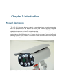
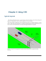
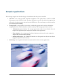
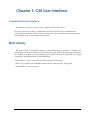
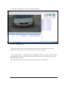
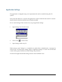
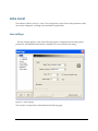
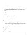
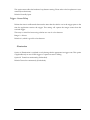
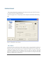
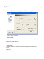
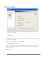
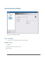
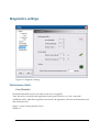
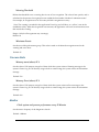
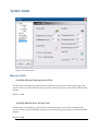
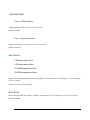
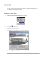
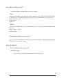
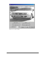
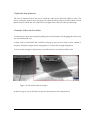
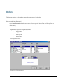
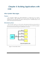
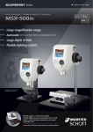
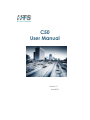
C50
User Manual
Version 1.3
May 2010
© Copyright 2009-2010 Hi-Tech Solutions, ltd.
Table of Contents
List of Acronyms ............................................................................................................................... 5
Safety Symbols .................................................................................................................................. 6
Other Symbols................................................................................................................................... 6
LED Safety Compliance ................................................................................................................... 6
Related Resources ............................................................................................................................. 7
1.
CHAPTER 1: INTRODUCTION ........................................................... 8
Product description .......................................................................................................................... 8
Product components ......................................................................................................................... 9
2.
CHAPTER 2: USING C50 .................................................................. 10
Typical Layouts .............................................................................................................................. 10
Embedded Computer .................................................................................................................... 11
Triggering ........................................................................................................................................ 11
Sample Applications ..................................................................................................................... 12
3.
CHAPTER 3: C50 USER INTERFACE .............................................. 13
Concepts of the User interface.................................................................................................. 13
Main display ................................................................................................................................... 13
Application Settings................................................................................................................... 15
Lane Level ....................................................................................................................................... 16
Lane settings ............................................................................................................................... 16
Illumination control ................................................................................................................... 18
Camera level ................................................................................................................................... 19
Auto-Gain.................................................................................................................................... 21
Add or Delete capture sets........................................................................................................ 22
Capture sets ................................................................................................................................ 23
General settings ............................................................................................................................. 26
Save images settings...................................................................................................................... 28
Communication settings............................................................................................................... 31
Local – IP Address ..................................................................................................................... 31
SeeData Center ........................................................................................................................... 31
Diagnostics settings....................................................................................................................... 33
Performance Alerts .................................................................................................................... 33
Process Alerts.............................................................................................................................. 34
Monitor ........................................................................................................................................ 34
System Alerts .................................................................................................................................. 35
Memory Alerts............................................................................................................................ 35
Optional Alerts ........................................................................................................................... 36
Heat Alerts .................................................................................................................................. 36
Hard Drive .................................................................................................................................. 36
Live Video ....................................................................................................................................... 37
Entering live video mode .......................................................................................................... 37
Live video mode control ........................................................................................................... 38
Area of Interest ........................................................................................................................... 38
Options ............................................................................................................................................ 41
Set Font properties ..................................................................................................................... 42
4.
CHAPTER 4: BUILDING APPLICATIONS WITH C50 ...................... 43
Inter-System Messages ................................................................................................................. 43
Purpose ........................................................................................................................................ 43
Networked systems ................................................................................................................... 43
Client application on the server ............................................................................................... 44
Message structure ...................................................................................................................... 45
Future XML interface................................................................................................................. 46
5.
APPENDIX A: DOCUMENT HISTORY.............................................. 48
C50 user Manual - List of Acronyms
4
About This Guide
This document is a user manual for C50, a state-of-the-art vision based recognition
system for high speed roadside installations. The manual provides documentation for the
Graphic User Interface (GUI) and the interfaces from C50 to external systems.
List of Acronyms
Acronym
Meaning
BW
Black and white
DLL
Dynamic Link Library
GUI
Graphic User Interface
HTS
Hi-Tech Solutions
HW
Hardware
ID
Identification
IO
Input / Output
IP
Internet Protocol
LAN
Local Area Network
LED
Light Emitting Diodes
LPR
License Plate Recognition
OS
Operating system
PC
Personal computer
PS
Power Supply
SDK
Software Development Kit
SW
Software
TBL
Terminal Block
TOS
Terminal Operating System
C50 user Manual - List of Acronyms
5
Safety Symbols
Observe all safety statements to help prevent loss of service, equipment damage, personal
injury, and security problems. This guide uses the following safety symbols:
Important: An Important statement calls attention to information important
to the reader.
WARNING: A warning statement calls attention to a situation that can
result in harm to hardware or equipment.
HAZARD: A hazard statement calls attention to a situation that could
cause personal injury if the hazard is not avoided by following the
instructions provided.
Other Symbols
A Note statement calls your attention to additional information.
LED Safety Compliance
The C5 illumination unit complies with International Standard IEC 60825-1, for Class 1
LED (light emitting diodes) products containing Class 1 LED’s. This Class 1 LED product
poses no hazard to the user or to any other person present near the illumination unit. Use
of the illumination unit is totally safe and needs no specific precautions.
WARNING: Do not look directly into the camera for more than a few
seconds.
C50 user Manual -
6
Related Resources
For more information on C50 and related systems, see the following guides. You can
download them from http://www.htsol.com.
♦ C50 installation manual – Provides hardware, mechanical and software installation
and maintenance instructions
♦ SeeData ICD – Integratorʹs Interface control document
C50 user Manual -
7
1.
Chapter 1: Introduction
Product description
The HTS C50 high-speed all-in-one system is a sophisticated image processing system that
tracks cars plates and reads and identifies their license plate numbers. This highly integrated
computer/camera/illumination unit performs all of the functions of an LPR system with its
embedded microprocessor and SeeCar recognition package.
The C50 is intended for high speed lanes, up to 200 KM/H, and is normally installed on gantries
over the highway. The C50 can be part of a broader city-wide surveillance system, free-flow toll
road billing system, or border crossing. It connects to a central server and control room using the
SeeData Networking application.
Photo 1.1: C50 in dual camera enclosure
Product components
The C50 includes:
• An Embedded high performance Single Board Computer (SBC)
• Windows standard embedded 2009
• Mega pixel cameras (single or dual)
• Integrated, pulsed solid state illumination (IR or visible)
• Built-in embedded software-based, motion detection (VMD) trigger
• Recognition results output interface over wired or wireless network
• Continuous operation, day and night, including adverse weather conditions
• SeeData Server for central reporting and for recognition image storage of multiple units
• Weatherproof outdoor enclosure and bracket for installation
The system can be ordered with one of the following options:
• Stereo-Recognition utilizing a second integrated illumination camera unit (for extended field
of view)
• Overview camera to record a color picture of the vehicle (in the stereo configuration)
Not included and to be provided by others:
•
Installation and integration of system with end-user applications.
C50 user Manual - Product components
9
2.
Chapter 2: Using C50
Typical Layouts
The following illustration shows a typical layout of the C50 solution, with 2 lanes and typical
ranges for US type plates. In this case the recognition is for the rear plates.
The C50 has built-in illumination used to illuminate the plate for recognition purposes. A choice
of IR or visible solid-state illumination is available, mounted inside the camera head. However, for
color overview of the vehicle body, an external white-light illumination is required.
Figure 2.1: Typical C50 configuration on gantry (external illumination is optional for body
overview)
C50 user Manual - Typical Layouts
10
Other typical layout may include front plates and front/rear stereo. For the latter mode - a
combination of front and rear plates - each side will require a separate C50 unit and additional
client application is required to be installed in the lane controller.
Embedded Computer
The C50 system is based on an integrated Dual-Core Single Board Computer (SBC), which manages the
unit, controls the recognition cycle and communicates with the network. The typical configuration is one
C50 per lane, installed within the camera enclosure housing, thus reducing roadside equipment exposure
and maintaining the integrity of system performance as well as hardware accessibility. Recognition results
from the lane unit are sent to the central server PC.
Triggering
The C50 system utilizes either a hardware-based or a software based trigger (video motion detection) for
its operation. For multi-lane configuration, hardware based (laser or other) triggers are commonly applied
and installed on the gantry structure, however fast ground loop controllers (GLC) are also an option.
C50 user Manual - Embedded Computer
11
Sample Applications
The following sample cases describe the type of installations that the system is installed:
•
Toll road – the system provides automatic recognition of the plates that is used for Vehicle
Enforcement System (VES) toll roads. The plate information can track the vehicles driving thru the
toll road as a backup in case it does not have the RFID device. The saved image can also be used for
proof and exception handling.
•
Average Speed – using outputs of several sites, a back end program can be used to calculate the
average speed of the vehicles, based on the time of journey. The average speed can be used for:
•
o
Enforcement (speed violation). The average speed can be used to issue violation tickets. A
sample client application (SeeCarSpeed) is available for this application.
o
Flow estimation – the average speed and time of journey can be used for road conjunction
analysis that can assist traffic planning.
o
On-line traffic report – the roadside information can be reported on web sites in order to
supply live reports from the freeway.
Monitoring – the recognition information may be used for various security applications.
C50 user Manual - Sample Applications
12
3.
Chapter 3: C50 User Interface
Concepts of the User interface
This chapter provides an overview of the Graphical User Interface (GUI).
The GUI is used only for setup or maintenance activities. Since the unit is a standalone unit
without a physical display, the user interface will be seen only in a remote session using a remote
control display such as ʺremote desktop connectionʺ.
Main display
The main window is designed to display as much information as possible in a friendly user
interface (the user does not need to switch between any child windows during normal operation).
The window is divided into several display panes, where each pane is responsible for a single
system task. The different panes are described below:
- Image Display - shows video from the camera (from one of the lanes)
- History Log - displays list of identified vehicles (index, code, lane, time, image path)
- Status Window - system messages
C50 user Manual - Main display
13
An example of such display is shown in the following figure:
Figure 3.1: C50 main display
The vehicle that is shown was captured with a front camera and is displayed on the image
display. Its license number is shown in the top-left corner above the image.
The event information - including the license plate number, date/time of the event, lane number
and image path - are shown in the left/bottom scrollable history list. Up to 1000 recent events are
displayed in the history list.
The system status events (time, states and messages) are shown in the right list.
C50 user Manual - Main display
14
Application Settings
The application is configured using a set of parameters that can be controlled using the C50
options.
This section describes how to set the C50 application in order to obtain the best results. It assumes
that all software, hardware and drivers are already installed.
How to reach Settings? There are three ways to get Application Settings:
1.
Open Settings from the main menu
2.
Click on the
3.
Open Settings with hot key F8
in the tool bar
When trying to open ʺSettingsʺ as a standard user, rather than an administrator, a message box
with the text ʺYou donʹt have change rights to application settingsʺ. In such case all the inner
screens will be grayed and the user cannot change any parameter.
Note that C50 application default settings fit most of the installation cases.
C50 user Manual - Main display
15
Lane Level
The number of lanes is always 1, since C50 is a single lane system. Each of the parameters of the
lane can be configured, according to the installation requirements.
Lane settings
The lane settings display is seen in the following figure. It configures the lane with general
parameters, and additional information is defined at a lower (camera level) setting.
Figure 3.3: Lane settings
This window’s components are described in the following page.
C50 user Manual - Lane Level
16
Lane name
A lane name is sometimes handy to assist the user while servicing multiple lanes.
The optional lane name editing is possible by editing lane label on the left tree control. It is
similar to renaming in Windows Explorer: make focus on the lane label by mouse click; by second
click enter editing mode and change the label. In the example above the lane name is ʺLane1ʺ and
could be changed to, e.g., ʺNorth Laneʺ. Note that the lane name is used only as a title for the C50
display.
Trigger
Trigger Type
Defines the type of trigger –
Hardware trigger - external-hardware (loop detector, laser)
Software VMD (Video Motion Detection) – Camera 11
Software VMD (Video Motion Detection) – Camera 12
Default: Hardware Trigger
Trigger - Capture on Sensor –
Defines when the image capturing process starts. This timing is in reference to the input sensor:
“Rising” when the input goes low to high; “Falling” when the input goes high to low.
Example: if a loop detector is used as a trigger, and the detector normally-open signal is
connected to the C50 unit, then the trigger should be set to ʺRisingʺ for forward plate detection, or
ʺFallingʺ for rear plate detection.
Default: Rising (normally when a car steps on the loop for forward plates).
Trigger - Sensor Pin
Associates the I/O pin to the sensor.
Range: 1 – 2.
Default: Defaults to pin 1.
Trigger - Sensor is normally open
C50 user Manual - Lane Level
17
This option must reflect the hardware loop detector setting. Please refer to the loop detector’s user
manual (for technicians).
Default: Normally Open.
Trigger - Sensor Delay
Defines the time in milliseconds between the time that the vehicle was in the trigger point to the
time the application receives the trigger. This setting will capture the images sooner than the
received trigger.
This entry is critical for fast moving vehicles in a case of a slow detector.
Range: 0 – 200 ms.
Default is 0, which is good for a fast detector.
Illumination
Option A: Illumination is switched on only during vehicle appearance in trigger zone. This option
is applicable only in case of HW trigger & “capture on sensorʺ=falling.
Option B: Turned on continuously (Unchecked).
Default: Turned on continuously (Unchecked).
C50 user Manual - Lane Level
18
Camera level
These settings determine the configuration of the camera(s) in the system. Each C50 can have 1
or 2 cameras, and each is configured separately.
The following figure shows a sample display, and its components are detailed in the following
page.
Figure 3.4: Recognition camera settings
Mac Address
Associates the camera to the lane by its MAC address, which is a unique identifier for the device.
Default: this value is read from the device by C50 and should normally be left at its original value.
Changing this settings item must be done in a cautious way. There is no option to connect the
same device to different lanes. The application will warn when you assign the same MAC
addresses for different lanes on the same PC but it cannot determine if you assign the same MAC
addresses for different lanes on different PCs.
C50 user Manual - Camera level
19
Illumination – LSB Pin
Associates the Terminal Block pin to the camera illumination control LSB (least significant bit - the
white wire). The MSB (most significant bit - the green wire) is connected to the next pin.
Range: 3-7.
Default: 3.
Images – Prefix
Defines the prefix for the image file name.
Default: “xy_” (where x is the lane number and y is the camera number) - e.g. “11_” for lane number 1 a
camera number 1.
Area of Interest
Defines the area inside the image in which the VMD detection is active. These parameters are
defined in Live Video.
Default: full frame. Left – 0, Right – 1376, Top – 0, Bottom – 515.
C50 user Manual - Camera level
20
Automatic Gain
Automatic Image Quality
When enabled, the auto-image quality function is activated. This function maintains the
brightness of the image to a desired brightness value, regardless of the changing environment, thus
increasing the image quality at bad light conditions. The calculation is done on basis of a moving
average of the last 10 vehicles. It will therefore adapt the camera signal gain and shutter speeds to
the changing environment light conditions. The mechanism repeats itself every 30 seconds until the
desired brightness is reached or it meets one of the limits (minimum and maximum gain or shutter
speed). If this option is enabled, the manual gain/shutter changing is disabled. Thus, the fields
cannot be changed in Live- video and capture-set pages.
Default: Disable.
Min. Gain
Minimal allowed gain value the system can set in the auto-gain function.
Default: 0.
Max. Gain
Maximal allowed gain value system can set in the auto-gain function.
Default: 253.
Min Shutter
Minimum shutter speed allowed for the automatic shutter control.
Default: Off
Max Shutter
Minimum shutter speed allowed for the automatic shutter control.
Default: 1/10000
Desired Brightness
The auto-gain function target value. It defines the desired image brightness, where 0 is totally black
and 255 is totally white.
C50 user Manual - Camera level
21
Default: 110.
Threshold
Allowed threshold for the desired brightness before system changes gain set direction. This value is
used to prevent the auto-gain function to bounce up and down around the proper value.
Default: 10.
Add or Delete capture sets
A capture set defines the number and type of images captured after the trigger. Its configuration is
defined in the next page. At the camera level setting you can add or remove a capture set, limited to 5
sets.
Add Capture set
Adds a capture set for this camera.
Remove Capture set
Removes a capture set for this camera.
C50 user Manual - Camera level
22
Capture sets
For each capture set that is defined, the user can configure its settings using the following
window which is opened while selecting the item under the camera settings.
Figure 3.5: Capture set definition
Image – Shutter
Defines the camera shutter speed for the capture set. This option is disabled if auto quality function
is enabled.
Range: 1/60 – 1/10,000 + shutter-off.
Default: 1/1000.
Image – Gain
Defines the gain setting for the capture set. This option is disabled if auto quality function is
enabled.
Range: 0-253
Default: 127.
C50 user Manual - Camera level
23
Start time
Defines the time of day to start this capture set. Not used in case of a single capture set. If another
set is defined, the capture set will end at the start time of the next set.
Default: 12:00 AM (noon time), not used in case of a single set.
Light intensity
Defines the illumination intensity for the current selected set item. Four levels can be selected: off,
low, medium and high intensity. This setting has no effect in case C50 does not control the
illumination, such as in the case of an external lamp.
Default: Medium.
Number of captures
Defines the number of images to capture in the selected set.
Range: 1-5
Default: 3.
Defaults
Sets the Illumination intensity to the default set; brightness, contrast and gain to default values.
C50 user Manual - Camera level
24
VMD
The Video Motion Detection (VMD) is a software algorithm which determines a trigger event
using a live stream of video from the camera. The software checks for changes inside a predefined
Area of Interest (AOI previously defined in the camera setting window). If there is a ʺsignificantʺ
change then the unit relates the change to a vehicle plate entering this area within the field of
view. The ʺsignificanceʺ of the change is controlled by the sensitivity parameter.
VMD sensitivity – determines the sensitivity of the software trigger. The higher sensitivities
cause more detection cases to occur than the lower sensitivities. The optimum value is related to
various site specific factors, such as the scenario and the type of camera.
Range: 1-20
Default - 10
C50 user Manual - Camera level
25
General settings
Figure 3.8: General settings
Smart Output
If set – the application will not send out recognition results (to both the application display and the
server) if there is no recognition.
Default: Not set (all recognition results are displayed)
Suppress Multiple Triggers
If set - the application filters recognition results made within a short time period (15 seconds). For
example, if 2 results of the same vehicle are observed within a few seconds, then only the first
recognition is reported.
Default: Disabled
C50 user Manual - General settings
26
Output Results in Unicode
If set – the results are set to Unicode (used in Korean and other special language sets).
Default: Not set
Add Offset of x to Each Lane Index
In order to define a different lane number, this parameter adds an offset to the reported lane number.
For each lane, this offset should be a unique value, so the reported lane number will identify the
location of the C50 unit.
Range: 0-10000
Default: 0 (No offset – the reported lane number will be 1)
Draw Selection Rectangle
If set – the Area of Interest (AOI) is drawn on the images in the images view.
Default: Not set.
State Recognition
If set – performs State recognition. Note that this mode requires a special license.
Default: set.
Close Live Video and Settings window after x minutes
When either Live-Video mode or the Settings window is on, the recognition process is stopped. In
order to prevent the system to remain in this state, an automatic process limits the time when these
diagnostic/setup windows are on. After this time the application reverts back to normal recognition
operation.
Range: 1-15 minutes
Default: 5 minutes
C50 user Manual - General settings
27
Save images settings
Figure 3.9: Save images control
Use Camera Prefix
If set, adds the camera prefix to the image file name.
Default: Set.
Save all Images
If set, save all intermediate images (as defined by the capture sets for all the lane’s cameras).
Default: not set (saves only the ‘best’ image).
C50 user Manual - Save images settings
28
Image Type
Jpeg
If set – saves the image in Jpeg compressed format.
Default: Jpeg
Jpeg Quality
Defines the quality level of saved jpg image. A higher quality looks better but is greater in size.
Typical sizes: IR camera: 18KB for low, 75 KB for high; Color camera: 50KB for low, 240 KB for high.
Default: Medium.
Image Type - Bitmap
If set – saves the image in bitmap uncompressed format. This creates very large files. Typical sizes are:
1400KB for IR, 4400 KB for color.
Default: Jpeg.
Images Main Directory
Local Path
Defines the local disk path where the images (and their sub-directories) are stored. User can use the
browse button (“…”) to select the path from the existing disk directory, or type a new path. The
application will create the directory if it does not exist.
Default: Working directory.
Output Share Name
If set – a network shared name can be defined in order to set the reported image path to a network
drive. This is useful if the message containing the image path is transmitted over the network, so the
remote node could access the image file name using the absolute path.
Default: Not set (image path is reported as a local drive)
C50 user Manual - Save images settings
29
Subdirectory Options
Create Subfolder for Each Lane
If set - the application opens a separate subdirectory for each of lanes.
Default: Create
Calendar Subfolder
The application can open a periodical (Daily / Weekly / Monthly) subdirectory under the images root
directory path. Another option is “None” if no subdirectories creation is desired.
Default: Create Daily (will open a new subdirectory every midnight).
C50 user Manual - Save images settings
30
Communication settings
Figure 3.10: Communication settings
Local – IP Address
The local PC’s TCP/IP address. Choose the desired IP address
SeeData Center
Enable
Activates the network-communication option.
Default: Disabled.
C50 user Manual - Communication settings
31
Center IP
The host PC TCP/IP address for sending recognition results.
Default: 0.0.0.0
Data Port
The host PC TCP/IP listening port number.
Default: 1368
C50 user Manual - Communication settings
32
Diagnostics settings
Figure 3.11: Diagnostics settings
Performance Alerts
Error Threshold
Defines the threshold to set an error alert in case of low recognition.
Note: The error is recorded in the application Event log and will show as a “red” state in the
SeeMonitor utility. When the recognition rate increases, the application will write an information event
that cancels the error.
Range: 0 - 100 (0 will not generate errors).
Default: 75
C50 user Manual - Diagnostics settings
33
Warning Threshold
Defines the threshold to set a warning alert in case of low recognition. The value is lane specific, and is
calculated as the percent of recognized events within the last number of defined “minimum events”.
For example, 21 recognitions out of 25 events yield 84% recognition accuracy.
Note: The warning is recorded in the application Event Log and will show as a yellow” state in the
SeeMonitor utility. When the recognition rate increases, the application will write an information event
that cancels the warning.
Range: 0-100 (0 will not generate any warnings).
Default: 85
Minimum Events
Sets the size of the performance group. This value is used to calculate the recognition rate for the
warning and error alerts.
Default: 25
Process Alerts
Memory warn (above) X %
Sets the value of C50 memory usage level from which the system writes a Warning message to the
system’s Events Log. If C50 memory usage is back to normal range, the system writes an Information
message.
Default: 70%
Memory Error (above) X %
Sets the value of C50 memory usage level from which the system writes an Error message to the
system’s Events Log. If C50 memory usage is back to normal range, the system writes an Information
message.
Default: 90%
Monitor
Check system and process performance every X Minutes
Sets the time’s frequency of the diagnostics checks.
Default: 1 Minute.
C50 user Manual - System Alerts
34
System Alerts
Figure 3.12: System alerts
Memory Alerts
Available Memory Warning (below) X mb
Sets the value of Free Memory usage level from which the system writes a Warning message to the
system’s Events Log. If Free Memory usage is back to normal range, the system writes an Information
message.
Default: 10 MB
Available Memory Error (below) X mb
Sets the value of Free Memory usage level from which the system writes an Error message to the
system’s Events Log. If Free Memory usage is back to normal range, the system writes an Information
message.
Default: 50 MB
C50 user Manual - System Alerts
35
Optional Alerts
Error – CPU fan failure
Enables the indication of a failure of the CPU fan.
Default: Enabled
Error – System fan failure
Enables the indication of a failure of the C50 system fan.
Default: Disabled
Heat Alerts
CPU temperature Error
CPU temperature Warn
SYSTEM temperature Error
SYSTEM temperature Warn
Defines the threshold temperature [in Centigrade] to set an alarm (error or warning) in case of overheating
(CPU or system)
Default: 70c (error) / 60c (warning)
Hard Drive
Defines the threshold disk capacity (in MB) to set an alarm (error or warning) in case of low disk space.
Default: 1000MB
C50 user Manual - Live Video
36
Live Video
Live video is used for setting up the camera, or checking its operation. During this mode the
recognition and normal operation is stopped.
Entering live video mode
1.
Open Live Video from the main menu (View a Live Video)
2.
Click on the
3.
Open Live Video with hot key F10
in the tool bar
An example of a live video display is seen in the following diagram:
Figure 3.13: Live video
C50 user Manual - Live Video
37
Live video mode control
Live Video Window groups all the C50 system’s cameras.
Gain
Sets the camera interface gain. Slide left or right to adjust the value, which will change the settings
for the live video. The updated parameter will also be saved and used as the current gain level,
unless auto gain is used.
Range: 0 to 63.
Default: 45.
Shutter
Sets the camera shutter. Slide left or right to adjust the value, which will change the settings for the
live video.
Range: 1/1000 – 1/10,000.
Default: 1/2000.
Illumination control (using right button)
User may change the illumination of the selected camera by clicking on right button and manually
selecting off / low / medium / high.
Area of Interest
How to define Area of Interest?
Check the traffic
In this screen, you are able to see the traffic in a live video mode.
C50 user Manual - Live Video
38
Figure 3.14: Live video example
C50 user Manual - Live Video
39
Define the Area of Interest
The Area of Interest (AOI) is the area in which the video motion detection (VMD) is active. The
AOI is a rectangle, which its sizes are equal or less than the whole image size. If the vehicle’s license
plate location is outside the AOI, LPR will never happen even if the car is shown in the image.
Draw the AOI on the Live Video:
Use the mouse to draw the rectangle by holding down the left button and dragging the mouse until
you reach the desired AOI.
A menu with two fields (SET and CANCEL) will pop up and you now need to select whether to
accept the AOI (the rectangle does not disappear) or to cancel (the rectangle disappears).
You can set the rectangle as many times as you like until you are satisfied with the AOI.
Figure 3.16 The AOI just before setting it.
In above image we can see AOI that can prevent the situation in the example above.
C50 user Manual - Live Video
40
Options
The Options settings can be used to change the appearance of the display.
How to reach Panes Properties?
Open Panes Properties from the main menu (View Properties Image Pane (or History Pane or
Status Pane))
Open Panes Properties using these buttons:
·
Image Pane
·
History Pane
·
Status Pane
The Properties screen:
Figure 3.17: Options settings
C50 user Manual - Options
41
There are 3 different screens, one for each pane (Image pane, History pane, Status pane)
Set Font properties
Font
Select one of the Font types within the list.
Default: Operating system’s default font.
Font Style
Select one of the Font styles within the list.
Default: Operating system’s default font (normally Regular).
Font Size
Select one of the Font size within the font’s available sizes.
Default: Operating system’s default font size.
Font Script
Select one of the Font scripts (languages) with the font’s available scripts.
Default: Operating system’s default font script.
C50 user Manual - Options
42
4.
Chapter 4: Building Applications with
C50
Inter-System Messages
Purpose
C50 is designed to report on the vehicle identifications to a central server over a wired or
wireless network. A client application on the server receives the messages and uses the
information for various purposes. For example, if the client process is a database interface, it will
insert each message data into the database.
Networked systems
The C50 systems connect over a local network, and transmit the results across the network to a
central system using the SeeData networking protocol. This can be seen in the following diagram.
The C50 units also copy their images to a local database on the server.
Figure 4.1: Networked solution
C50 user Manual - Inter-System Messages
43
Client application on the server
Each detected vehicle will generate one message containing the recognition result: the vehicle
number, an optional identification name, the data and time, the lane, and an optional image file
path (in jpg or bmp formats). The central server shares these recognition messages results from
all C50 units with a client application.
To process the recognition results the client application simply intercepts MSMQ (Microsoft
message queue) messages that are sent by C50 to the ʹClientʹ application(s).
Figure 4.2: Intercepting the messages on the server
The integration on basis of the MSMQ (or DDE for the sake of backward compatibility) message
mechanism is simple. An ICD (SeeData Interface Control Document) describes the interface. HTS
also provides client sources for VC++ or VB that show how to intercept these messages, provide
sample applications, and the simulation program, which allows testing it.
C50 user Manual - Inter-System Messages
44
Message structure
Each message contains the results of the recognition process, and one message is sent after each
trigger. The fields include:
•
Data and time
•
Lane number
•
Plate string
•
Image file path
•
Confidence
•
Other fields
This networking solution is compatible to all SeeCar products. So the cluster of units may
include C50 systems (high speed system), C5 (low/medium speed system), SeeLane systems (PC
based systems) and other product line configurations.
C50 user Manual - Inter-System Messages
45
Future XML interface
A future release of the C50 will include a XML (Extensible Markup Language) interface. This
is a plain text, Unicode based meta language. It will connect the C50 units directly to the
userʹs server without the intermediate SeeData interface.
Figure 4.3: XML interface
C50 user Manual - Inter-System Messages
46
This page is intentionally left blank for comments
C50 user Manual - Inter-System Messages
47
5.
Appendix A: Document History
Version
Version
Technical
#
Date
Writer /
Author
1.0
Dec 21, 2009
Yoram
Comment
Sections
Affected
New document
All
Amir's comments:
3
Reviewed
By
All
Hofman
1.1
Dec 22, 2009
Yoram
Main display,shutter speed, images
Hofman
Dani's comments:
1.2
Feb 17, 2010
Yoram
Change in screens and descriptions
3
All
3
All
Hofman
Dani's comments on version 2.2.9:
1.3
May 20, 2010
Yoram
Change in screens and descriptions
Hofman
C50 user Manual -
48