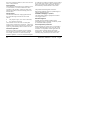
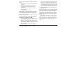
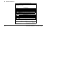
1
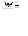
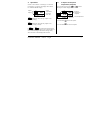
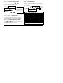
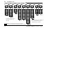
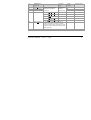
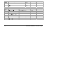
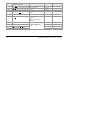
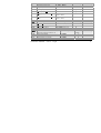
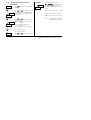
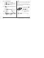
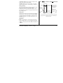
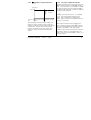
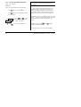
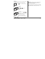
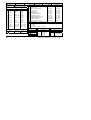
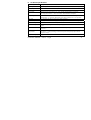
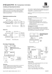
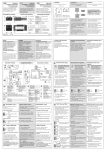
2132 and 2116 PID Temperature Controllers
Thank you for choosing the 2132 or 2116 Temperature Controller. Supplied in 1/32 and 1/16 DIN panel sizes they
are designed for accurate, stable control of ovens, chillers, sterilisers and other heating and cooling processes.
Two outputs are configurable for heating, cooling and alarms.
The controller is supplied configured according to the order code given in section 5. Check this on the side labels
to determine the configuration of your particular controller.
1. Dimensions and Installation
Model 2132
103mm (4.01in)
48mm (1.89in)
45mm
1.77in
-0.0, +0.6
-0.0, +0.02
Panel cut-out
24mm
Latching ears
22mm
-0.0, +0.3
0.88in
-0.0, +0.10
Panel retaining clips
Model 2116
45 x 45 mm
Panel cut-out
48mm
-0.0, + 0.6
1.77 x 1.77in
-0.00, +0.02
48mm (1.89in)
Part Number HA026270
Issue 5.0
103mm (4.01in)
Aug 07
1
1.1
To Install the Controller
Please read the safety information in sections 7 before proceeding.
1. Prepare the panel cut-out to the size shown
2. Insert the controller through the cut-out.
3. Spring the panel retaining clips into place. Secure the controller in position by holding it level and pushing
both retaining clips forward.
4. Peel off the protective cover from the display
1.2
Unplugging the Controller
The controller can be unplugged from its sleeve by easing the latching ears outwards and pulling it forward out of
the sleeve. When plugging it back into its sleeve, ensure that the latching ears click back into place to maintain the
IP65 sealing.
1.3
Recommended Minimum Spacing of Controllers
10mm (0.4 in)
38mm (1.5 in)
(Not to scale)
2
Part Number HA026270
Issue 5.0
Aug 07
2. Electrical Connections
Solid
State
Relay
(SSR)
Logic
I/O
1B
T/C
Pt100
OR
1B 1A
24
20-29 Vac/dc
Low voltage
supply
Model 2116
L
N
Model 2132
1A
A
V-
V+ AB
-
+ Output 2
N
Relay
2.49Ω
mA
Sensor Inputs
2.1
24
External Relay
Module (Operated
by the logic
output)
Wire Sizes
L
Line 85-264Vac 50/60Hz
Neutral
24 24
20-29 Vac/dc
Low voltage supply
The screw terminals accept wire sizes from 0.5 to 1.5 mm
(16 to 22AWG). Hinged covers prevent hands or metal
making accidental contact with live wires. The rear
terminal screws should be tightened to 0.4Nm (3.5lb in).
Part Number HA026270
A
OR
Issue 5.0
Aug 07
Solid
State
Relay
(SSR)
AB
Logic
I/O
1A
V+
1B
V-
Line
85-264Vac
Neutral 50/60Hz
Output 2 Relay
+
-
2.49Ω
T/C Pt100 mA
Sensor Inputs
Output ratings
Logic Output: 9Vdc, 12mA (non-isolated from
sensor input).
Used for: Heating, Cooling or Alarm.
Relay Output: 2A, 264V ac resistive.
Used for: Heating, Cooling or Alarm.
Contact Closure Input (replaces Logic Output).
Used for: Alarm Acknowledge or Timer start/reset
3
2.2
Typical Wiring Diagram
Heater fuse
Line
Circuit
Breaker
Controller fuse
2A type T
Solid State
Relay
(e.g. TE10)
1B
1A
V- V+ A
Model 2132
A
L
N
Heater
Neutral
+
Thermocouple
Snubber*
Cooling or
alarm relay
Safety requirements for permanently connected equipment state:
Relay
output
fuse
2A type T
* When switching
inductive loads such as
contactors or solenoid
valves, wire the
22nF/100Ω ‘snubber’
supplied across relay
terminals AA & AB. This
will prolong contact life
and reduce interference.
! WARNING
Snubbers pass 0.6mA at
110V and 1.2mA at
230Vac, which may be
sufficient to hold on high
impedance loads. Do not
use in these installations.
•
•
A switch or circuit breaker shall be included in the building installation
It shall be in close proximity to the equipment and within easy reach of the operator
It shall be marked as the disconnecting device for the equipment
4
Part Number HA026270
Issue 5.0
Aug 07
3. Operation
3.1
Switch on the controller. Following a 3 second selftest sequence, you will see the display shown below.
It is called the HOME display.
Press and release quickly the
or
button.
The setpoint will be displayed for 2 seconds.
Output 1
Output 2
OP1
OP2
20
Actual
Temperature
(or Process
Value ‘PV’)
OP1
illuminates when the logic output is ON
(normally heating).
OP1
OP2
To Adjust The Required
Temperature (Setpoint)
OP1
OP2
20
60
Required
temperature
(Setpoint)
Actual temperature
**
Press and hold
to raise the setpoint
Press and hold
to lower the setpoint
OP2
illuminates when the relay output is ON
(normally cooling or alarm).
If OP1 or OP2 are configured as alarm outputs
(instead of heating and cooling), they will flash when a
new ‘unacknowledged’ alarm occurs and go steady
when the alarm is acknowledged but still true.
Part Number HA026270
Issue 5.0
Aug 07
5
3.2
To View The Display Units
Press and release quickly the
or
display units will be flashed for 0.5 sec.
0.5 sec
o
C
20
button. The
C Deg Centigrade
F Deg Fahrenheit
*
K Deg Kelvin
Linear inputs - no
units displayed
*
*
and
together will
If you get lost, pressing
always return you to the HOME display.
If, at any time, no key is pressed within 45 seconds,
the display will always return to the HOME display.
To Acknowledge a New Alarm
Press
and
together. This will also reset any
latched alarms that are no longer true.
6
Alarm Messages
If an alarm occurs a message will be flashed in the
display. This alternates with the measured temperature
as shown below:
Display Units
or
3.3
3.4
Actual
temperature
1fsL
20
Alarm 1
Full Scale
Low
Possible messages
Alarm - Full Scale High
Alarm - Full Scale Low
Alarm - Deviation
Alarm - Deviation High
Alarm - Deviation Low
Sensor Break
Loop Break
Load Fail
End of Timing
In place of the dash the alarm number is shown Alarm 1 or 2 or 3.
-fsH
-FSL
-deV
-dHi
-dLo
Sbr
Lbr
Ldf
End
Part Number HA026270
Issue 5.0
Aug 07
3.5
To View The Output Power
Do this if you want to see how much heating or
cooling energy is being demanded by the controller.
Note: This is not a measure of actual power.
HOME display
20.0
Press twice quickly
Warning!
*
C
OP 100.0
Press
or
Controller is
demanding 100% heat
In manual standby mode (see ‘To Use The Timer’) the
output power can be adjusted by the operator, causing
heating or cooling to be permanently applied. To
prevent this make the OP parameter read only (see ‘To
Hide, Reveal And Promote Parameters’)
to view the value
Press
Part Number HA026270
Issue 5.0
Aug 07
7
3.6
To Select or Change Other
Parameters
Parameters are settings in the controller which you can
change to suit the process. They are found under list
headings.
button to step through the list headings
Press the
as shown below.
Turn to paragraph 3.8 to see all of the list headings.
These lists are used to:
• Change alarm setpoints
• Tune the controller to the process
• Manually select PID values
• Change setpoint limits and access the in-built
timer
• Change input and output limits
HOME display
20.0
X2
aL
Atun
Keep pressing
to select
more list headings, eventually
returning to the HOME display.
This is a continuous loop.
8
Part Number HA026270
Issue 5.0
Aug 07
3.7
Press
To Adjust The Alarm Setpoints
(Trip Levels)
Press
or
displays List indicating a list heading
2 secs
twice to choose the AL list.
0.5 sec
*
20
C
2nd press
There are three Alarms. The setpoint for each alarm is
found under the AL list. If an alarm has been disabled, it
will not appear in this list.
Note: The other parameters listed in section 3.8 are
accessed and adjusted in exactly the same way as this
example.
-FSL = Low alarm
-FSH = High alarm
-dEV = Deviation
-dHi = Deviation High
-dLo = Deviation Low
- = the alarm number
* Press
or
to
change the setpoint.
Press
Issue 5.0
Next list
Press
1st press
Part Number HA026270
LiSt
AL
Aug 07
and
0
Alarm 1
*
0
Alarm 2
*
0
Alarm 3
*
1---
2---
3---
together to return to the HOME display.
9
3.8
Parameter Lists
Home
List
X2
Alarm
List
20.0
AL
OP
1---(1)
w.SP
2---
m A
3---(1)
diSP
(1)
Autotune
List
Atun
PID
List(2)
Pid
Setpoint
List
Input
List
SP
Access List
Output
List(2)
On/Off
List
iP
oP
On.Of
ACCS
tunE
Pb
SP L
FiLt
OP.Lo
HYS.H
codE
AdC
ti
SP H
CJCO
OP.Hi
Hys.C
Goto
td
SPrr
mV
CYC.H
HC.db
Conf
rES
tm.OP
OFS
CYC.C
Lcb
tmr
CAL.P
Ont.H
Hcb
dwel
CAL
Ont.C
rEL.C
StAt
Pnt.L
HY
Lb t
(1) In place of dashes, the last
three letters depend on the
alarm type.
OFS.L
Pnt.H
OFS.H
(2) Either the PID list or the On/Off list
will be present depending upon the
configuration of the controller.
Shaded boxes are hidden when shipped from the factory.
To reveal see ‘’To Hide, Reveal and Promote Parameters” section 3.10
10
Part Number HA026270
Issue 5.0
Aug 07
3.8.1
Summary
1.
Press
to step across list headings.
2.
Press
to step down parameters
3.
Press
to view the value of a parameter. Keep pressing to decrease the value.
4.
Press
to view the value of a parameter. Keep pressing to increase the value
Part Number HA026270
Issue 5.0
Aug 07
11
3.9
Parameter Tables
Home List
Adjustable Range
Op
Output
Power
-100% = max cooling, 100.0% = max heating.
w.SP
Working
Setpoint
Only appears when setpoint rate limit enabled
Manual/
Auto
mAn
m-A
Auto Select
disp
Home
Display
Options
Automatic control selected
OP
Displays the output power - for use as
a manual station. (Only applies to
software version 1.4)
the
AL.SP
pv.aL
Read only
Read only
Auto
Standard - Shows the process value
with the setpoint accessed by pressing
PV
Customer setting
Manual standby selected
Std
NonE
Default setting
and
Std
buttons.
Blank Display (only alarm messages
flashed)
Displays the Process Value only
Displays the Alarm 2 Setpoint only
Displays the Process Value with Alarm
2 Setpoint accessed by
12
and
.
Part Number HA026270
Issue 5.0
Aug 07
AL
Alarm List (See
section 3.7)
1---
Alarm 1 Setpoint
2---
Alarm 2 Setpoint
3---
Alarm 3 Setpoint
In place of dashes, the last
three letters indicate the
alarm type:
-FSL
Full Scale Low
-FSH
Full Scale High
-dEv
Deviation
-dHi
Deviation High
-dLo
Deviation Low
Adjustable
Range
Default
Setting
Between low
and high
0
setpoint limits
0
0
HY
Alarm Hysteresis
1 to 9999 in display units (This value is
common to all alarms) Hysterisis is used to
prevent the alarm output ‘chattering’ by setting
a difference between the alarm switch ON and
switch OFF points
1
Lb t
Loop Break Time
OFF to 9999 minutes
OFF
Part Number HA026270
Issue 5.0
Aug 07
Customer setting
13
Atun
Automatic Tuning List (See section 4.3)
tunE
Automatic Tune Enable
OFF or on
Off
Adc
Automatic Manual reset calculation (when P+D
control)
man or
caLc
man
Adjustable
Range
Default Setting
PID List (See section 4.3)
Adjustable Range
Pb
Proportional Band
1 to 999.9 display units
ti
Integral Time
OFF to 9999 seconds
360
td
Derivative Time
OFF to 9999 seconds
60
rES
Manual Reset Value
-100 to 100.0 %
0.0
PiD
Default Setting
Customer setting
Customer setting
20
(only present if ti= OFF)
Lcb
Low Cutback
Auto to 999.9 display units
Auto
Hcb
High Cutback
Auto to 999.9 display units
Auto
rEL.C
Relative Cool Gain
0.01 to 10.00
14
1.00
Part Number HA026270
Issue 5.0
Aug 07
SP
Setpoint List (See also ‘To Use
the Timer’ section 3.11)
Adjustable Range
SP L
Setpoint Low Limit
-1999 to 999.9
As per order
SP H
Setpoint High Limit
-1999 to 999.9
As per order
sprr
Setpoint Rate Limit
0FF to 999.9 display units
per minute
tm.OP
Timer Operating Mode
Opt.1 to Opt.5
tmr
Time Remaining
0 to 9999 minutes
dwEl
Dwell Time
0FF to 9999 minutes
OFF
StAt
Timer Status
OFF or on
OFF
Part Number HA026270
Issue 5.0
Aug 07
Default Setting
Customer setting
Off
OPt.1
0
15
iP
Input List (See also ‘User
Calibration’ section 4.2)
Adjustable Range
FiLt
Input Filter Time Constant
0FF to 999.9 seconds
CJC*
Cold Junction Temperature measured at rear terminals
Read only
Millivolt Input measured at the rear terminals
Read only
mV
Default Setting
-1999 to 9999 display
units
OFS
Process value Offset
CAL.P
Calibration Password
0 to 9999
CAL
User Calibration Enable
FACt Re-instates factory
calibration
Customer setting
1.6
0
3
FACt
USEr Re-instates user
calibration
Pnt.L
Low Calibration Point
OFS.L
Low Point Calibration Offset
Pnt.H
High Calibration Point
OFS.H
High Point Calibration Offset
16
0
-1999 to 9999 display
units
0
100
0
Part Number HA026270
Issue 5.0
Aug 07
oP
Output List
Adjustable Range
OP.Lo
Low Output Power Limit
-100 to 100.0 %
OP.Hi
High Output Power Limit
-100 to 100.0 %
100.0
CYC.H
Heating Output Cycle Time
0.2 to 999.9 seconds
1.0 Lgc 20 Rly
CYC.C
Cooling Output Cycle Time
0.2 to 999.9 seconds
5.0 Lgc 20 Rly
ont.H
Heating Output Minimum On
Time
Auto to 999.9 seconds
(Auto = 50ms)
Auto
ont.C
Cooling Output Minimum On
Time
Auto to 999.9 seconds
(Auto = 50ms)
auto
onOF
On Off Output List
Adjustable Range
Default Setting
hYS.H
Heating Hysteresis
1 to 9999 display units
1
hYS.C
Cooling Hysteresis
1 to 9999 display units
1
HC.db
Heat/Cool Deadband
0 to 9999 display units
0
ACCS
Access List (See “To Hide, Reveal and
Promote” parameters section 3.10)
Adjustable Range
Default
Setting
codE
Goto
Conf
Access Pass Number
Go To Required Access Level
Configuration Pass Number
0 to 9999
Oper, Ful, Edit, conf
1
OPEr
2
Part Number HA026270
Issue 5.0
0 to 9999
Aug 07
Default Setting
Customer setting
0
Customer setting
Customer setting
17
3.10
To Hide, Reveal and Promote
Parameters
ACCS
Press
PASS
codE
Press
Edit
Goto
Press
reached.
until the Access List Heading is
Press
or
to enter the password.
The factory default is 1. ‘PASS’ will be
displayed when the correct password has
been entered.
or
to select ‘Edit’ level.
Press
Other options are:
OPEr Operator level - shows selected
parameters
FuLL Reveals the ‘FULL’ set of
parameters
ConF Gives access to configuration
level.
Example:
HidE
2FSH
High alarm 2 has been selected.
When
or
is pressed, instead of
displaying the parameter value, its
availability to in Operator level is shown as
follows:
ALtr
The parameter will be
HidE
.
rEAd
The parameter will be hidden
Pro
alterable
The parameter will be read-only
The parmeter will be ‘promoted’
into the HOME list (see below).
Press to return to the Access list header.
You are now in Edit level.
ACCS
18
Press
and
in the normal way.
to select a parameter
Part Number HA026270
Issue 5.0
Aug 07
3.10.1 The Pro (Promote) option
3.10.2 Returning to Operator level
Up to twelve commonly used parameters can be
‘promoted’ into the HOME list. This will give the
operator quick access to them by simply pressing the
Repeat the above procedure for all the parameters you
wish to hide, promote, or make read-only then return
to operator level:
button. This feature, used in combination with
‘hide’ and ‘ read only’, allows you to organise the way
in which you want your controller formatted.
OPer
Goto
Example:
Pro
tmr
Time remaining has been selected.
Press
or
1.
Press
until you reach the
ACCS list heading
2.
Press
Goto
until you reach
3.
Press
Oper
or
4.
Press
level
to return to Operator
to choose Pro.
The parameter tmr will now appear in the HOME
list. Repeat the procedure for any other parameters
you wish to promote.
to select
To remove a parameter go to edit level, select the
parameter from the relevant list and change the choice
from Pro back to ALtr, rEAd or HidE.
Part Number HA026270
Issue 5.0
Aug 07
19
3.11
In reset
To Use The Timer
Press
until you reach the SP list
•
Press
until you reach the tM.OP parameter
•
or
to select the timer operating
Press
mode, Opt.1 to Opt.5 as follows:
•
In reset, you can switch between automatic control and
standby mode, using the parameter m-A in the HOME
list.
The controller is supplied with the m-A parameter
hidden. You must first reveal it. See ‘To Hide, Reveal
and Promote Parameters’.
3.11.1 Opt.1 - Mode 1, Dwell and Switch Off
Auto
Temperature
Setpoint
Standby mode
Waiting to
reach
temperature
Reset
Press
Auto
mAn
End flashes
Timing
Running
20
m-A
End
From the HOME display press
until the m-A parameter is displayed.
Press
display
and
or
to select:
Automatic control
Standby mode. (the MAN
beacon below OP2 will
illuminate)
together to return to the HOME
Part Number HA026270
Issue 5.0
Aug 07
‘Automatic control’ means control at setpoint, with
heating (and cooling) being applied.
‘Standby mode’ means: the controller is in manual
with zero output power. See ‘Warning!’ in section 3.5.
During Running
The controller will always switch to automatic control.
Heating (or cooling) will be applied and the
temperature will rise (or cool) to the setpoint. When
the temperature is within 1oC of setpoint, the timer will
start counting down.
During End
When the timer times out, the controller will switch to
standby mode. The MAN beacon will light and End
will be flashed in the main display. The process will
cool down. The timer will remain indefinitely in this
state until reset.
3.11.2 Opt.2 - Mode 2, Dwell No Switch Off
Temperature
Setpoint
Indefinite dwell
at setpoint
Waiting to
reach
temperature
Reset
End flashes
Timing
End
Running
This is the same as mode 1 except that at the end of the
timing period the controller will continue indefinitely in
automatic control.
When Reset
End will stop flashing. The controller will return to
reset in standby mode. It can be returned to automatic
control by setting the parameter m-A in the HOME list
to Auto.
Part Number HA026270
Issue 5.0
Aug 07
21
3.11.3 Opt.3 - Mode 3, Time from Cold and
Switch Off
Temperature
3.11.4 Opt.4 Mode 4, Time from Cold No
Switch Off
Temperature
Setpoint
Standby mode
Setpoint
Indefinite dwell
at setpoint
End flashes
End flashes
Reset
Timing
End
This is the same as mode 1 except that the timer will
start counting down immediately without waiting for
the temperature to reach setpoint.
22
Reset
Timing
End
This is the same as mode 2 except that the timer will
start counting down without waiting for the controller
to reach setpoint.
Part Number HA026270
Issue 5.0
Aug 07
3.11.5 Opt.5 Mode 5, Delayed Switch On
Temperature
Setpoint
Reset
Indefinite dwell
at setpoint
Timing
Reset
This mode applies a time delay before turning on the
heating (or cooling). When the timer is started, the
controller will always switch to standby mode and start
counting down. When the timer has timed out, the
controller will switch into automatic control, apply
heating (or cooling) and control indefinitely at the
setpoint.
Part Number HA026270
Issue 5.0
Aug 07
3.11.6 To Program a Ramp-Dwell profile
A simple ramp-dwell profile can be programmed using
Sprr (setpoint rate limit) in combination with the
timer. To use this feature, first reveal Sprr and w.SP
(the working setpoint) using the method described in
“To Hide, Reveal and Promote” parameters. w.SP will
then appear in the HOME list.
Set Sprr to the required ramp rate. It is adjustable
in 1/10th of the least significant display units per
minute. That is if the display is configured 0 to
1000oC, setpoint rate limit can be adjusted between 0.1
and 999.9 oC per minute.
When setpoint rate limit has been enabled and the
timer is started, the working setpoint, wsp, will first
step to the measured temperature and then ramp at the
setpoint rate limit, sprr, to the target setpoint.
In modes 1 and 2 timing will start when the measured
temperature is within 1oC of the target setpoint. In
modes 3 and 4 it will start when wsp is within 1oC of
the target setpoint.
23
3.12
To Start And Reset The Timer
There are two methods:
TIP: Promote tmr to the HOME list for quick access,
as described in ‘To Hide, Revealing and Promote
Parameters.
Method 1.
This is the simplest method to control the timer.
until you reach the SP list
•
Press
•
Press
until you reach the tMr parameter
(time remaining).
1234
Tmr
Press
or
to enter
Press
the required timing period in
minutes. (0 to 9999).
to return to the HOME display
As soon as a value is entered into tmr timing will
commence. tmr will count down towards zero.
During the timing period tmr can be increased or
decreased according to the demands of the process.
Setting the value to zero will end the timing period.
When tmr reaches zero. ‘end’ will flash in the main
display. The timer will remain indefinitely in this state
until a new value is entered, when the timer will
restart.
To reset the timer, press
‘end’ will stop flashing .
and
together.
To restart the timer, enter a new value into tmr.
24
Part Number HA026270
Issue 5.0
Aug 07
Method 2.
Use this method if you want to set a fixed time and use
the stat parameter to start and stop the timer.
Press
sp
to reach the SP List heading.
Press until you reach dwel
1234
dwel
The stat parameter can also be switched between
Off and run by configuring the logic I/O as a
Off/run contact closure input.
Open the external contact to select run. This is an
edge triggered action. Close the contact to select Off.
Off is forced whenever the contact is closed.
Dwell time
or
to enter a
Press
timing period in minutes
(0-9999).
Timer Status
run
stat
Press
and
To start the timer, press
or
to
select run.
The dwell time will be loaded into tmr
and timing will commence.
To reset the timer, select Off.
The time remaining tmr will be set to
0.
together to return to the HOME display.
Part Number HA026270
Issue 5.0
Aug 07
25
4. Configuring the Controller
Select configuration level to change: •The type of control •The display units •The input sensor type• The
scaling of linear inputs •The alarm configuration • The passwords.
4.1
ACCS
To select configuration level
Press
to reach the Access List Heading.
Press
codE
Press
to step across the configuration list headings.
inSt
PASS
Press
or
to enter the
password. The factory default is 1.
PASS will be displayed when the
correct password has been entered.
conF
Press
iP
AL
AA
Exit
pASS
1A
Press
Goto
or
to select conf
Press
or
to enter the
configuration level password. The
factory default is 2. PASS will be
PASS
ConF
displayed when the correct password
has been entered.
Press to enter configuration level.
Press
26
Having selected a list heading, press
parameter within a particular list.
Press
and
to select a
to change the setting.
To Instrument Configuration Tables
Part Number HA026270
Issue 5.0
Aug 07
4.1.1
Instrument Configuration
inst
unit
Instr Conf
Display units
dEC.P
Decimal
places in
display
CtrL
Control type
Act
Control
action
Options
*C
*F
*K
nonE
nnnn
nnn.n
nn.nn
Pid
On.OF
AL
rEv
dir
Part Number HA026270
Issue 5.0
Description
Centigrade
Fahrenheit
Kelvin
None
None
One
Two
PID Control
On/off Control
Convert to an
alarm unit
Reverse
(normal action
for
temperature
control)
Direct (output
decreases as
PV falls below
SP)
Aug 07
Inst
Pd.tr
Instr Conf
Manual
reset
tracking (PD
control)
Options
HoLd
trAc
Description
In Auto holds
manual reset
value
In Auto tracks
output for
bumpless A/M
transfer
27
4.1.2
Input Configuration
iP
Sensor
Input
Options
Meaning
inPt
Input
type
j.tc
k.tc
L.tc
r.tc
b.tc
n.tc
t.tc
S.tc
PL 2
rtd
mV
C.tc
J thermocouple
K thermocouple
L thermocouple
R thermocouple
B thermocouple
N thermocouple
T thermocouple
S thermocouple
Platinell II
CJC
(TC
only)
28
Cold
junction
compen
sation
100Ω PRT
Linear mV
Custom input
C=default
Auto
Automatic
0*C
0°C external ref.
45*C
45°C external ref.
50*C
50°C external ref.
Linear input scaling (Range -12 to +80mV)
InP.L
mV input
low
InP.H
mV input
high
Displayed value
VAL.H
VaL.L
Displayed
value low
VAL.H
Displayed
value high
ImP
Sensor
break
OFF
Off (Linear
inputs only)
input
impedance
Auto
1.5KΩ
Hi
5KΩ
HiHi
15KΩ,
VAL.L
Inp.L
Part Number HA026270
Issue 5.0
mV
Inp.H
Aug 07
4.1.3
Alarm Configuration
The AL list configures the three internal ‘soft’ alarms
and causes the appropriate alarm message to be flashed
in the HOME display.
At this stage the alarm is indication only (known as a
‘soft alarm’). To make the alarms operate the relay or
logic outputs, follow the instructions under “Relay and
Logic input/output Configuration.
AL
Alarm
Type
Meaning
AL 1
Alarm 1
OFF
The alarm is
disabled
Full Scale Low
alarm
Full Scale High
alarm
Deviation band
alarm
Deviation high
alarm
Deviation low
alarm
fsL
fsH
dEv
dHi
dLo
Part Number HA026270
Issue 5.0
Aug 07
AL
Alarm
Type
Meaning
Ltch
Alarm
latching
no
YES
Non-latching
Latched with
automatic*
resetting.
Latched with
manual**
resetting.
No blocking
mAn
bLoc
Alarm
blocking
No
YES
Blocked until
first good
The above sequence is repeated for:
AL 2 (Alarm 2) and AL 3 (Alarm 3)
Sp.Li
Alarm
setpoint
diS
limits
Con
Limited by
display range
Limited by
setpoint limits
* Automatic resetting means that, once the alarm has
been acknowledged, it will automatically clear when it
is no longer true.
** Manual resetting means that the alarm must first
clear before it can be reset.
29
4.1.4
Relay and Logic input/output
Configuration
Aa
1a
The logic I/O can be configured as an output or a
contact closure input for alarm acknowledge, keylock,
or timer run/reset.
Aa
1a
id
Relay
Logic I/O
Identity of
output
Func
Function
These
functions
only
appear for
the logic
I/O
diG.F
30
Digital
output
functions
See ‘To
Options
Meaning
rELy
LOG
diG
Relay
Logic
Digital (alarm)
output
Heating output
Cooling output
PDSIO mode 1
Alarm
Acknowledge
Keylock digital
input
Run/reset timer
No change
Clear all alarms
Alarm 1 (Note 1)
Alarm 2 (Note 1)
HEAt
COOL
SSr.1
Ac.AL
Loc.b
rres
noch
CLr
1FSL
2FSH
SenS
Relay
Logic I/O
Operate
the Relay
or Logic
Output
from an
Alarm or
Digital
Function
section
4.1.5”
Options
Meaning
3FSL
NW *
SBR*
LBR*
LDF*
MAn *
EnD*
TMG*
TMG*
(Note 2)
TMG3*
TMG4*
Sense of
the
output
nor
Inv
Alarm 3 (Note 1)
New alarm
Sensor break
Loop break
Load fail alarm
Man mode active
End of timing
Timer running
Timer counting
down
Timer running
Timer counting
down
Normal (Note 3)
Inverted (Note 3)
* Alarms always non-latching. Process alarms 1, 2
and 3 are configurable as alarm latching or nonlatching, see the ‘AL’ List
Part Number HA026270
Issue 5.0
Aug 07
Note 1: The last three letters will correspond to the
alarm type configured in the AL list. If the alarm is
disabled, AL1 or AL2 or AL3 will be shown.
5.
Note 2: If tmg.3 and tmG.4 are selected, they
illuminate the logic or relay output beacons, OP1 and
OP2, without operating the actual output. They are
used to indicate that timing is in progress while leaving
the actual outputs to be operated by the other digital
functions such as the END condition which can be
used to operate an external klaxen.
6.
Note 3: Normal is the usual setting for heating or
cooling.
Inverted is the normal setting for alarms - de-energise
in alarm.
4.1.5
1.
2.
3.
4.
To Operate the Relay or Logic output
from an alarm or digital function.
Press
Press
Press
Press
function
until you reach Func
or
to select Func = diG
to reach diG.F
or
to select a alarm or digital
Part Number HA026270
Issue 5.0
Aug 07
Leave for 2 seconds. The display returns to
diG.F and connects the selected alarm or digital
function to the relay or logic output.
Press
or
again. Two decimal points will
appear in the function that has been added to the
output.
4.1.6
Multiple Alarms on one Output
Any number of alarms or digital functions can be
added to the relay or logic output by repeating steps 4,
5 and 6 above. Two decimal points will appear in
those functions that has been added to the output.
4.1.7
1.
2.
3.
To Clear Alarms from an Output
Press
until to reach diG.F
or
to select CLr
Press
Leave for 2 seconds. The display returns to
diG.F which disconnects all alarms from the
relay.
31
4.1.8
4.1.9
Passwords
PASS
Passwords
Range
Default
ACC.P
Full and Edit
level password
0-9999
1
CnF.P
Configuration
level password
0-9999
2
CAL.P
User
calibration
password
0-9999
3
32
Press
To leave Configuration level
to reach the ‘exit’ display
Exit
YES
Press
or
to select ‘YES’ After 2 secs the display
will blink and return to the HOME display in Operator level.
Part Number HA026270
Issue 5.0
Aug 07
4.1.10 Diagnostic Alarms
In addition to the normal process alarms, the following
diagnostics alarm messages are provided.
Message
Meaning and (Action)
Message
Meaning and (Action)
EE.Er
Electrically Erasable Memory Error:
Err3
Error 3: Watchdog fail.
(Return for repair)
A parameter value has been corrupted.
Contact Eurotherm Controls.
HW.Er
(Return for repair)
LLLL
Low display range exceeded:
(Check input signal)
HHHH
High display range exceeded:
(Check input signal)
Err1
Err4
Error 4: Keyboard failure. Stuck
button, or a button was pressed during
power up.
Err5
Error 5: Input circuit failure.
Hardware error:
Error 1: ROM self-test fail.
(Return for repair)
Pwr.F
Power failure. The line voltage is too
low.
TU.Er
Tune Error. Appears if auto-tuning
exceeds 2 hours.
(Return for repair)
Err2
Error 2: RAM self-test fail.
(Return for repair)
Part Number HA026270
Issue 5.0
Aug 07
33
4.2
User Calibration
Your controller has been calibrated for life against
known reference sources. User calibration allows you
to apply offsets to compensate for sensor and other
system errors. The parameter OFS in the IP list
applies a fixed offset over the whole display range.
You may also apply a 2-point calibration as follows:
•
Press
until you reach the iP list
•
Press
until you reach the CAL.P parameter
•
or
to enter the password. The
Press
factory default is 3. PASS will be displayed
when the correct has been entered.
•
Press
•
Press
or
, to select User (FAct will
restore the factory calibration)
•
to select in turn the four parameters
Press
or
to set
shown in the graph below. Use
the desired calibration points and the offsets to be
applied at each point. The iP list on section 3.9
describes each of the parameters.
34
Displayed Value
User calibration
OFS.H
Factory calibration
OFS.L
Pnt.L
Pnt.H
Factory
calibration
to reach the CAL parameter
Part Number HA026270
Issue 5.0
Aug 07
4.3
Automatic Tuning
In PID control, the output from the controller is the
sum of three terms: Proportional, Integral and
Derivative. These three terms deliver just the right
amount of power to hold the temperature at setpoint
without oscillation. For stable control, the PID values
must be ‘tuned’ to the characteristics of the process
being controlled. In the 2132 and 2116 this is done
automatically using advanced tuning techniques.
Automatic tuning is performed by switching the output
of the controller On and Off to induce an oscillation in
the measured temperature. From the amplitude and
period of the oscillation, the PID values, shown in the
table below, are calculated.
Parameter
Proportional
band
Display
Pb
Integral time
ti
Part Number HA026270
Meaning or Function
The bandwidth in °C or °f
over which the output
power is proportioned
between minimum and
maximum.
Determines the time taken
by the controller to
remove steady-state error
signals.
Issue 5.0
Aug 07
Parameter
Derivative
time
Display
td
Low cutback
Lcb
High
Cutback
Hcb
Relative cool
gain
rEL.C
Meaning or Function
Determines how strongly
the controller will react to
the rate-of-change of
temperature.
The number of °C or °f
below setpoint at which
the controller will cutback
the output power to
prevent overshoot on heat
up.
The number of °C or °f
above setpoint at which
the controller will increase
the output power to
prevent undershoot on
cool down.
Only present if cooling has
been configured. Sets the
cooling proportional band
by dividing the Pb value by
the rEL.C value.
35
If the process cannot tolerate 100% heating or cooling
during tuning, the power can be restricted by the
heating and cooling limits in the Output list. However,
the measured value must oscillate to some degree for
the tuner to determine values.
Tuning is normally performed only once during the
initial commissioning of the process. However, if the
process under control subsequently becomes unstable
(because its characteristics have changed), you can retune again at any time.
It is best to tune starting with the process at ambient
temperature. This allows the tuner to calculate more
accurately.
4.3.1
Heating & Cooling Output Cycle Times
Before commencing a tuning cycle, set the values of
CYC.H (heating output cycle time) and CYC.C
(cooling output cycle time) in the oP (output) list.
For a logic heating output (switching a SSR), set
CYC.H to 1.0 sec.
4.3.2 Tuning Procedure
1. Set the setpoint to the value at which you will
normally operate the process.
2. In the ‘Atun’ list, select ‘tunE’ and set it to
‘on’
3. Press the Page and Scroll buttons together to
return to the HOME display. The display will
flash ‘tunE’ to indicate that tuning is in progress.
4. The controller will induce an oscillation in the
temperature by turning the heating on and then
off.
5. After two cycles of oscillation the tuning will be
completed and the tuner will switch itself off.
6. The controller will then calculate the tuning
parameters and resume normal control action.
If you want ‘Proportional only’ or ‘P+D’ or ‘P+I’
control, you should set the ‘ti’ or ‘td’ parameters to
OFF before commencing the tuning cycle. The tuner
will leave them off and will not calculate a value for
them.
For a relay output, set CYC.H to 20.0 sec.
For a logic cooling output used to control a solenoid
valve, set CYC.C to 5.0 sec.
36
Part Number HA026270
Issue 5.0
Aug 07
4.3.3
Typical automatic tuning cycle
Temperature
1.
2.
3.
4.
Time
4.3.4
Calculation of the cutback values
When low cutback or high cutback is set to ‘AuTo’
their values will be fixed at three times the
proportional band, and will not be altered during
automatic tuning. If set to any other value, they will
be calculated as part of the tuning process.
4.4
Manual Tuning
If for any reason automatic tuning gives unsatisfactory
results, you can manually tune the controller.
Proceed as follows:
5.
Set the Integral Time ‘ti’ and Derivative Time
‘td’ to OFF.
Set High Cutback ‘Hcb’ and Low Cutback
‘Lcb’, to ‘Auto’
Ignore the fact that the temperature may not settle
precisely at the setpoint
Reduce the proportional band ‘Pb’ until the
temperature just starts to oscillate. If the
temperature is already oscillating, increase the
proportional band until it just stops oscillating.
Allow enough time between each adjustment for
the temperature to stabilise. Make a note of the
proportional band value ‘B’ and the period of
oscillation ‘T’.
Set the PID parameter values according to the
formula below:
Type of
control
Proportional
band ‘Pb’
2xB
Integral
time
‘ti’
OFF
Proportional
only
P+I
P+I+D
Derivative
time ‘td’
OFF
2.2xB
1.7xB
0.8xT
0.5xT
OFF
0.12xT
With the process at its normal running temperature:
Part Number HA026270
Issue 5.0
Aug 07
37
4.4.1
Setting the cutback values
Temperature
The above procedure sets up the parameters for
optimum steady state control. If unacceptable levels of
overshoot or undershoot occur during start-up or for
large step changes in temperature, then manually set
the cutback parameters Lcb and Hcb.
Proceed as follows:
1. Set the low and high cutback settings to 3 x the
proportional band (that is to say, Lcb = Hcb =
3 x PB).
2. Note the level of overshoot or undershoot that
occurs for large temperature changes (see the
diagrams below).
In example (a) increase Lcb by the overshoot value.
In example (b) reduce Lcb by the undershoot value.
Temperature
Overshoot
Undershoot
Example (b)
Time
When the temperature approaches the setpoint from
above, you can set Hcb in a similar manner.
4.4.2
Manual reset
When ti = OFF manual reset (rES) appears in the
PiD List. This parameter sets the output power
when the error signal is zero. It can be manually
adjusted to remove steady state error - the function
normally performed by the Integral term.
Example (a)
Time
38
Part Number HA026270
Issue 5.0
Aug 07
5. Ordering Code
The controller is supplied configured according to the ordering code shown below.
Model number
Function
Model Number
2132
1/16 DIN
2116
1/8 DIN
CC
NF
TC
TN
VH
VL
Function
PID controller
On/Off
controller
PID controller
+ timer
On/Off
controller +
timer
XXX
ENG
FRA
GER
NED
SPA
SWE
ITA
Supply voltage
Manual
None
English
French
German
Dutch
Spanish
Swedish
Italian
Supply voltage
85-264Vac
20 -29Vdc or
ac
Part Number HA026270
Issue 5.0
Aug 07
Manual
Output 1 (Logic)
Output 1: Logic
XX
Disabled
Logic output
LH
Heating
LC
Cooling
M1
PDSIO mode 1
FH
High alarm 1
FL
Low alarm 1
DB
Dev band alarm 1
DL
Dev. low alarm 1
DH
Dev. high alarm 1
NW
New alarm
Logic input
AC
Alarm ack/reset
KL
Keylock
TM
Timer Run/Reset
Output 2 (Relay)
Output 2: Relay
XX
RH
RC
FH
FL
AL
DB
DL
DH
NW
Disabled
Heating
Cooling
High alarm 2
Low alarm 2
High alarm 2 & low
alarm 3
Dev band alarm 2
Dev. low alarm 2
Dev. high alarm 2
New alarm
39
Sensor input
Sensor input
Setpoint min
Display range and
Setpoint min & max limits
Thermocouples
J
Type J
K
Type K
T
Type T
°C
-210 to
1200
-200 to
1372
-200 to 400
L
Type L
-200 to 900
N
Type N
-200 to
1300
-50 to 1768
-50 to 1768
0 to 1820
0 to 1369
R
S
B
P
Type R
Type S
Type B
Platinell
II
Resistance thermometer
Z
Pt100
-200 to 850
40
°F
-340 to
2192
-325 to
2500
-325 to
750
-325 to
1650
-325 to
2370
58 to 3200
-58 to 3200
32 to 3308
32 to 2496
-325 to
1562
Setpoint max
Units
Ext relay module
Custom downloaded inputs
Input adaptor
Range OC
C
Type C -W5%Re/W26%Re (default
0 to 2319
custom sensor)
D Type D - W3%Re/W25%Re
0 to 2399
E
E thermocouple
-200 to 999
1
Ni/Ni18%Mo
0 to 1399
2
Pt20%Rh/Pt40%Rh
0 to 1870
3
W/W26%Re (Engelhard)
0 to 2000
4
W/W26%Re (Hoskins)
0 to 2010
5
W5%Re/W26%Re (Engelhard)
10 to 2300
6
W5%Re/W26%Re(Bucose)
0 to 2000
7
Pt10%Rh/Pt40%/Rh
200 to 1800
8
Exegen K80 I.R. Pyrometer
-45 to 650
Process inputs (linear) Scaleable -999 to 9999
M
Y
A
V
Range OF
32 to 4200
32 to 4350
-325 to 1830
32 to 2550
32 to 3398
32 to 3632
32 to 3650
50 to 4172
32 to 3632
392 to 3272
-49 to 1202
-9.99 to +80mV
0 to 20mA
4 to 20mA
0 to 10Vdc (input adapter required)
Units
C
°C
F
°F
K
Kelvin
X
Linear I/P
External relay module
XX
Not fitted
R7
Fitted
(Operated by
the logic
output)
Part Number HA026270
Input Adaptor
XX
None
V1
0-10Vdc
A1
0-20mA sense
resistor (2.49Ω.
0.1%)
Issue 5.0
Aug 07
6. Technical Specification
Panel sealing
IP65 (EN 60529), or 4X (NEMA 250)
Operating ambient
0 to 55oC. Ensure that the enclosure is adequately ventilated. 5 to 95%RH, non condensing
Storage temperature
-30oC to +75oC. (Protect from humidity and dust)
Atmosphere
Not suitable for use above 2000m or in explosive or corrosive atmospheres
Power supply
High voltage unit: 100 to 240Vac -15%, +10%, 48-62Hz, 5Watts maximum consumption
Low voltage unit: 24Vdc/ac +/- 20%. DC to 62Hz, 5Watts maximum consumption
Relay rating (isolated)
Maximum: 264Vac, 2A resistive. Minimum: 12Vdc, 100mA
Mechanical life > 107 operations. Electrical life at 1A, 240vac resistive load > 5 x10⁶ operations
Wire sizes
Use a minimum of 0.5mm2 or 16awg wire for plant connections.
Over current protection
Use independent 2A fuses for the supply and relay output. Suitable fuses are EN60127 (type T)
Logic I/O rating
9V at 12mA, non-isolated from sensor input
Electrical safety
Meets EN 61010 (Voltage transients on the power supply must not exceed 2.5kV). Pollution
degree 2.
Isolation:
All isolated inputs and outputs have reinforced insulation to protect against electric shock. (See live
sensor note)
Cold Junction
Compensation
>30 to 1 rejection of ambient temperature changes in automatic mode. Uses INSTANT
ACCURACY TM sensing technology to reduce warm up drift and respond quickly to ambient
temperature changes.
Installation Category
Category II or CAT II
Part Number HA026270
Issue 5.0
Aug 07
41
7. Safety and EMC Information
This controller is intended for industrial temperature
and process control applications when it will meet the
requirements of the European Directives on Safety and
EMC. Use in other applications, or failure to observe
the installation instructions of this handbook may
impair safety or EMC. The installer must ensure the
safety and EMC of any particular installation.
Safety
This controller complies with the European Low
Voltage Directive 73/23/EEC by the application of the
safety standard EN 61010.
Electromagnetic compatibility
It conforms with the essential protection requirements
of the EMC Directive 89/336/EEC, by the application
of a Technical Construction file. It satisfies the
general requirements of the industrial environment
defined in EN 61326. For more information on
product compliance refer to the Technical
Construction File.
42
GENERAL
The information contained in these instructions is
subject to change without notice. While every effort
has been made to ensure the accuracy of the
information, Eurotherm shall not be held liable for
errors contained herein.
Unpacking and storage
The packaging should contain an instrument mounted
in its sleeve, two mounting brackets for panel
installation and an Installation & Operating guide.
Certain ranges are supplied with an input adapter.
If on receipt, the packaging or the instrument is
damaged, do not install the product but contact your
supplier. If the instrument is to be stored before use,
protect from humidity and dust in an ambient
temperature range of -30oC to +75oC.
SERVICE AND REPAIR
This controller has no user serviceable parts. Contact
your supplier for repair.
Caution: Charged capacitors
Before removing the controller from its sleeve, switch
off the supply and wait at least two minutes to allow
capacitors to discharge. Failure to observe this
Part Number HA026270
Issue 5.0
Aug 07
precaution may damage the indicator or cause some
discomfort to the user.
Electrostatic discharge precautions
When the controller is removed from its sleeve, it is
vulnerable to damage by electrostatic discharge from
someone handling the controller. To avoid this, before
handling the unplugged controller discharge yourself
to ground.
Cleaning
Do not use water or water based products to clean
labels or they will become illegible. Isopropyl alcohol
may be used to clean labels. A mild soap solution may
be used to clean other exterior surfaces of the product.
Safety Symbols
The following safety symbols are used on the
controller:
!
Caution. Refer to the
accompanying documents
Personnel
Installation must only be carried out by qualified
personnel in accordance with instructions given in this
handbook.
Part Number HA026270
Issue 5.0
Aug 07
Enclosure of live parts
The controller must be installed in an enclosure to
prevent hands or metal tools touching parts that may
be electrically live.
Caution: Live sensors
The logic input/output is electrically connected to the
sensor input (e.g. thermocouple). In some installations
the temperature sensor may become live. The
controller is designed to operate under these
conditions, but you must ensure that this will not
damage other equipment connected to the logic
input/output and that service personnel do not touch
this connection while it is live. With a live sensor, all
cables, connectors and switches for connecting the
sensor and non-isolated inputs and outputs must be
mains rated for use in 240V ac CATII.
Wiring
Wire the controller in accordance with the wiring data
given in these instructions. Take particular care not to
connect AC supplies to the low voltage sensor input or
other low level inputs or outputs. Only use copper
conductors for connections, (except thermocouple).
Ensure that the installation complies with local wiring
regulations. In the UK use the latest version of the
43
IEE wiring regulations (BS7671) and in USA use NEC
Class 1 wiring methods.
Power Isolation
The installation must include a power isolating switch
or circuit breaker. This device should be in close
proximity to the controller, within easy reach of the
operator and marked as the disconnecting device for
the instrument.
Voltage rating
The maximum continuous voltage applied between
any of the following terminals must not exceed
240Vac:
•
•
relay output to logic, dc or sensor connections;
any connection to ground.
The controller must not be wired to a three phase
supply with an unearthed star connection. Under fault
conditions such a supply could rise above 240Vac with
respect to ground and the product would not be safe
Conductive pollution
Electrically conductive pollution must be excluded
from the cabinet in which the controller is mounted.
For example, carbon dust is a form of electrically
conductive pollution. To secure a suitable atmosphere
44
in conditions of conductive pollution, fit an air filter to
the air intake of the cabinet. Where condensation is
likely, for example at low temperatures, include a
thermostatically controlled heater in the cabinet.
This product has been designed to conform to
BSEN61010 installation category II, pollution degree 2.
These are defined as follows:Installation Category II (CAT II)
The rated impulse voltage for equipment on nominal
230V supply is 2500V.
Pollution Degree 2
Normally only non conductive pollution occurs.
Occasionally, however, a temporary conductivity caused
by condensation shall be expected.
Over-temperature protection
When designing any control system it is essential to
consider what will happen if any part of the system
should fail. In temperature control applications the
primary danger is that the heating will remain
constantly on. This could damage the product, the
machinery being controlled, or even cause a fire.
Part Number HA026270
Issue 5.0
Aug 07
Reasons why the heating might remain constantly on
include:
• the temperature sensor becoming detached from
the process
• thermocouple wiring becoming short circuit;
• the controller failing with its heating output
constantly on
• an external valve or contactor sticking in the
heating condition
• The controller setpoint too high
Where damage or injury is possible, we recommend
fitting a separate over-temperature protection unit,
with an independent temperature sensor, which will
isolate the heating circuit.
Please note that the alarm relays within the controller
will not give protection under all failure conditions.
Installation requirements for EMC
• For general guidance refer to Eurotherm Controls
EMC Installation Guide, HA025464.
• It may be necessary to fit a filter across the relay
output to suppress conducted emissions. The filter
requirements will depend on the type of load. For
typical applications we recommend Schaffner
FN321 or FN612.
Part Number HA026270
Issue 5.0
Aug 07
•
If the unit is used in table top equipment which is
plugged into a standard power socket, then it is
likely that compliance to the commercial and light
industrial emissions standard is required. In this
case to meet the conducted emissions requirement,
a suitable mains filter should be installed. We
recommend Schaffner types FN321 and FN612.
Routing of wires
To minimise the pick-up of electrical noise, the sensor
input wiring should be routed away from high-current
power cables. Where this is impractical, shielded
cables should be used for the signal wiring. Where
signal wiring is carrying (or could carry, under fault
conditions) hazardous voltages*, double insulation
should be used.
* A full definition of ‘Hazardous’ voltages appears
under ‘Hazardous Live’ in BS EN61010. Briefly,
under normal operating conditions Hazardous voltage
levels are defined as >30V RMS (42.2V peak) or
>60V dc.
45
8. RoHS Certificate
Restriction of Hazardous Substances (RoHS)
Product group
2100
Table listing restricted substances
Chinese
限制使用材料一览表
产品
2100
铅
X
O
X
X
印刷线路板组件
附属物
显示器
模块
O
X
汞
O
O
O
O
镉
X
O
O
X
有毒有害物质或元素
六价铬
O
O
O
O
多溴联苯
O
O
O
O
多溴二苯醚
O
O
O
O
表示该有毒有害物质在该部件所有均质材料中的含量均在SJ/T11363-2006
标准规定的限量要求以下。
表示该有毒有害物质至少在该部件的某一均质材料中的含量超出SJ/T11363-2006
标准规定的限量要求。
English
Restricted Materials Table
Product
2100
PCBA
Enclosure
Display
Modules
O
X
Pb
X
O
X
X
Hg
O
O
O
O
Toxic and hazardous substances and elements
Cd
Cr(VI)
PBB
X
O
O
O
O
O
O
O
O
X
O
O
PBDE
O
O
O
O
Indicates that this toxic or hazardous substance contained in all of the homogeneous materials for
this part is below the limit requirement in SJ/T11363-2006.
Indicates that this toxic or hazardous substance contained in at least one of the homogeneous
materials used for this part is above the limit requirement in SJ/T11363-2006.
Approval
Name:
Position:
Martin Greenhalgh
Quality Manager
Signature:
Date:
IA029470U450 (CN23172) Issue 1 Feb 07
46
Part Number HA026270
Issue 5.0
Aug 07