1
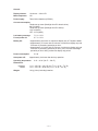
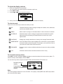
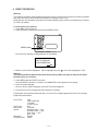
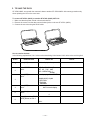
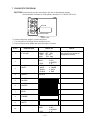
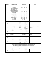
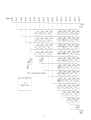
(without price)
SF-4700L (ZX-454 A,B)
SF-4900L (ZX-454 E,F)
JUL. 1997
SF-4700L
R
CONTENTS
1. SPECIFICATIONS ............................................................................................................ 3
2. GENERAL GUIDE ............................................................................................................. 5
3. BATTERY REPLACEMENT ............................................................................................. 8
4. RESET OPERATION ........................................................................................................ 9
5. TO SAVE THE DATA ...................................................................................................... 10
6. PIN FUNCTION ............................................................................................................... 12
7. DIAGNOSTIC PROGRAM .............................................................................................. 13
8. ERROR MESSAGE .........................................................................................................17
9. SCHEMATIC DIAGRAMS ...............................................................................................19
10. EXPLODED VIEW ...........................................................................................................21
11. PARTS LIST ....................................................................................................................22
—2—
1. SPECIFICATIONS
Memory Capacity
Memory capacity differs according to model. The following shows the memory capacity for each available
model.
Model
Memory
SF-4700L
64K bytes
SF-4900L
128K bytes
The following shows the number or items that can be stored in each model (SF-4700L/4900L).
Telephone Directory
Approximately 2900 (SF-4700L)/6000 (SF-4900L), under the following conditions:
8-character name
10-character telephone number
Approximately 1400 (SF-4700L)/3000 (SF-4900L), under the following conditions:
8-character name
10-character telephone number
20-character address
Memo
Approximately 2700 (SF-4700L)/5700 (SF-4900L), 20-character memos.
Schedule Keeper
Approximately 1800 (SF-4700L)/3800 (SF-4900L), under the following conditions:
1 item per day, 20 characters per item
30 days per month
Starting time specified,alarm time set
Approximately 2100 (SF-4700L)/4500 (SF-4900L), under the following conditions:
1 item per day, 20 characters per item
30 days per month
Starting time specified, no alarm time
Reminder
Approximately 3600 (SF-4700L)/7400 (SF-4900L), under the following conditions:
10 characters per item
Alarm time set
Approximately 4000 (SF-4700L)/8400 (SF-4900L), under the following conditions:
10 characters per item
No alarm time
Main Modes:
Telephone Directory, Memo, Schedule Keeper, Reminder, Calendar, Home Time, World Time and Calculator
Data Storage:
Storage and recall of telephone, memo, schedule, reminder data; calendar display; secret area; editing;
memory status display
Clock:
Worldtime; reminder alarm; schedule alarm; daily alarm; accuracy under normal temperatures: average ±3
seconds per day
Calculation:
10-digit arithmetic calculations; arithmetic constants (+, –, ×, ÷); independent memory; percentages; square
roots; 20-digit approximations; date calculations; other mixed calculations
—3—
General:
Display element:
16-column × 4-line LCD
Main component:
LSI
Power supply:
Three lithium batteries (CR2032)
Current consumption:
Telephone top menu (Backlight from EL doesn't shine)600 µA (MAX.)
Telephone top menu (Backlight from EL shines)12.6 mA (MAX.)
OFF- 19 µA (MAX.)
Low battery message:
7.2 V ± 2.5%
Forced power off:
6.7 V ± 2.5%
Battery life:
• Approximately 300 hours of continuous display only in Telephone Mode.
• Approximately 170 hours with 55 minutes of continuous display only and
5 minutes of processing operation per hour.
• Approximately 110 hours with 55 minutes of continuous display only and
5 minutes of processing operation per hour, plus 3 minutes of backlight
operation per hour during continuous display only period.
Power consumption:
Auto power off:
0.2 W
Approximately 6 minutes after last key operation
Operating temperature:
0 °C ~ 40 °C (32 °F ~ 104 °F)
Dimensions:
Unfolded:
Folded:
11 H × 152.5 W × 181.5 D mm (3/8" H × 6" W × 71/8" D)
15 H × 152.5 W × 93 D mm (5/8" H × 6" W × 35/8" D)
Weight:
138 g (4.9 oz) including batteries
—4—
2. GENERAL GUIDE
The following illustration shows the names of the main controls of the SF-4700L/4900L.
Display
Mode Keys
Power OFF
Key
Power ON/
Clear key
Numeric
Keys
Cursor Keys
Connector
Terminal
Light key
Keyboard
Lock
Setting Up the SF Unit
After batteries are loaded, use the following procedures to set up the SF Unit for operation.
To switch power on and off
1. Press ON to switch power on.
•
The initial screen for the mode that was seleted when you last switched power off appears on the
display.
•
lf either of the messages (A or B) shown bellow appears on the display, follow the procedures
described bellow.
Whenever you turn on the power of the SF Unit ,it performs a self-check before beginning operation.
If a problem is discovered during the self-check, the SF Unit displays one of the following messages.
Note
•
The above messages always appear in English, regardless of the system language setting.
If this is the first time you ever turned on the SF Unit...
Perform the RESET OPERATION on page 9.
If this is not the first time you are using the SF Unit...
There is probably a problem with the data in memory (data error). Note that once data is lost it cannot
be recovered. Such data errors are generally caused by one of the following problems.
•
Interruption of battery power.
•
Severe electrostatic charge, impact, change in temperature, or change in humidity.
•
Hardware problem.
—5—
After a data error is discovered, you will not be able to input or edit data. In order to return memory to
normal (allowing further input and editing of data), you must perform the RESET operation to clear the
memory of all data. Before doing so, you may want to recall important data and write it down (if you don't
already have a copy). You can then re-input the data after clearing the memory.
The RESET procedure you should use depends on the type of message error message on the display.
"ARE YOU USING A NEW UNIT FOR THE FIRST TIME ?"
1. Make sure that NO is highlighted and then press set. If YES is highlighted, press
to move the
highlighting to NO and then press SET.
• The message "DATA ERROR ! CHECK YOUR USER'S GUIDE FOR PROCEDURE !" appears on the
display at this time.After this message appears, you can press CLEAR to clear it from the display and
recall data in order to make a back-up record of it before continuing.
2. Press the RESET button, which is located inside the battery compartment cover on the back of the unit.
• This causes the "CLEAR MEMORY AND SET UP THE UNIT FOR OPERATION ?" message to
appear on the display.
3. Press to move the highlighting to YES and then press SET to reset the uint.
• Highlighting NO and pressing SET clears the reset message and displays the Home Time screen.
"CLEAR MEMORY AND SET UP THE UNIT FOR OPERATION ?"
1. Make sure that YES is highlighted. If OFF is highlighted, press to move the highlighting to YES.
• Highlighting OFF and pressing SET turns off the unit without resetting the unit.
2. Press SET to reset the unit.
If you still have trouble after trying the RESET operation, you may have a hardware problem.
•
lf a low battery power message appears on the display or if the display remains blank when you
turn power on, replace batteries as soon as possible.
2. press OFF to switch power off.
About Auto Power Off function...
The SF Unit is equipped with an Auto Power Off function that switches power off automatically whenever you do not perform any key operation for about six minutes. To restore power, press ON.
To turn on the EL backlight
There are two ways to turn on the backlight of the display.
Pressing LIGHT causes the backlight to turn on for about 15 seconds, and then turn off automatically.
Pressing SHIFT and then LIGHT also turns on the backlight, but in this case the backlight stays on as
long as you keep performing key operations on the SF Unit .
The backlight turns off automatically if you do not perform any key operation for about 15 seconds.
Leaving the backlight on for long periods greatly reduces battery life!
You can manually turn the backlight off by pressing LIGHT again.
Failure of the backlight to turn on indicates low battery power. Replace batteries as soon as possible.
—6—
To adjust the display contrast
1.
•
2.
3.
Enter the Telephone Directory Mode.
You could enter any mode except the Calculator mode here.
Press SHIFT CONT.
Use the and keys to adjust the contrast.
4.
After you are finished, press ESC to clear the contrast abjustment display.
To select a mode
Press one of the mode keys to select the mode you want.
TEL
Telephone Directory mode for storage of telephone numbers, name, addresses,
and six user-definable entries.
MEMO
Memo mode for storage of unformatted data in a kind of electronic notebook.
SCHEDULE
Schedule Keeper mode for storage of appointments scheduled for specific
dates and times, and setting of Schedule Alarms to remind you of your
appointments.
CALENDAR
Displays any monthly calendar from January 1901 through December 2099.
HOME/WORLD
Home Time/World Time modes for display of the current time in your hometown
and other locations around the globe. For example, you can set New York as
your home time and London as the world time.
REMINDER
Reminder mode to create reminders and alarms for annual, monthly, and daily
events.
CAL
Calculator mode for basic calcuations with the touch of a key.
To check the memory status
Press SHIFT and then hold down CAPA to display a screen that shows the current memory status. To
clear the memory status display, release CAPA.
You can enter any mode except the calculator Mode and Home/World Time Mode here
Remaining memory
capacity
Total number of
characters stored in
memory
Note
The screen example shown here is the SF-4900L. The capacity values(FREE and USED total) is different on the SF-4700L display.
—7—
3. BATTERY REPLACEMENT
Before replacing the batteries, note the following precaution:
• Be sure to replace all batteries with a full set of new ones, and do not mix old batteries with new ones.
1. Press OFF to switch power OFF.
2. Slide the battery compartment cover in the direction indicated by the arrow.
+3
2
+
1
+
3. Slide the battery switch to the "REPLACE 1" setting.
REPLACE
+3
3
2
1
2
+
1
+
NORMAL
4. Remove the battery holder by sliding it in the direction indicated by the arrow in the illustration.
Caution
Be sure to remove only one battery at a time. Otherwise, you will lose all data stored in memory.
5. Replace the old battery with a new one, making sure that the positive (+) side of the new battery is facing
up (so you can see it).
6. Replace the battery holder and faten it in place.
7. Slide the battery switch to the "REPLACE 2, 3" setting and repeat steps 4 through 6 for the other batteries.
• Be sure to replace all three batteries, using CR2032 lithium batteries only. Never mix old batteries with new
ones.
8. Slide the battery switch to the "NORMAL" setting.
• You will not be able to turn the unit on if the battery switch is not in the "NORMAL" setting.
9. Replace the battery compartment cover.
• The Home Time screen always appears whenever you turn power on for the first time after replacing
batteries.
10. Check the Home Time setting and make changes if necessary.
—8—
4. RESET OPERATION
Warning!
The following procedure erases all data stored in the memory of the SF Unit. Perform the following operation
only when you want to delete all data and initialize the settings of the SF Unit.
Remember-you should always keep copies of important data by writing it down, by transferring it to another
SF-4700L (SF-4900L).
To reset the SF Unit's memory
1. Press ON to switch power on.
2. Open the battery compartment and press the RESET button.
+3
2
+
RESET button
1
+
• At this time the following message appears on the display.
CLEAR MEMORY AND
SET UP THE UNIT
FOR OPERATION?
YES/NO
3. Make sure that YES is highlighted. If NO is highkighted, press
to move the highlighting to YES.
Warning!
The next step deletes all data stored in the SF Unit's memory. Make sure that you really want to delete
the data before you continue!
4. Press SET to start the RESET procedure.
• After the RESET operation is complete, the LANGUAGE screen appears on the display.
5. Select a system language.
• After you set the system language, the Home Time Screen appears.
6. Check the Home Time setting and make changes if necessary.
Following the reset operation described above, the Home Time display appears and the SF Unit settings
initialized as noted below.
Home Time:
World Time:
Daily Alarm:
Sound:
Messages:
Character input:
LON
JAN/1/1998 THU
12:00 AM
12-hour format
NYC
12:00 PM
Schedule alarm — ON
Reminder alarm — ON
Daily alarm — OFF
Key — ON
English
CAPS
—9—
5. TO SAVE THE DATA
SF-4700L/4900L can transfer the customer's data to another SF-4700L/4900L with memory protection only
when replacing the LCD or the outer case.
To connect SF-4700L (4900L) to another SF-4700L (4900L)CSF Unit
1. Make sure that the power of both units are switched off.
2. Remove the covers from the data communications jacks on the two SF-4700L (4900L).
3. Connect the two units using the SB-62 cable.
How to transfer the data
In the following explanations, Unit 1 refers to the transmitting Unit whereas Unit 2 refers to the receiving Unit.
STEP
OPERATION
DISPLAY
Press [ON] button on Unit
2.
Mode display before power off
1
2
Press RESET button on
Unit 2.
Press [SET] button on
Unit 2.
CLEAR MEMORY AND
SET UP THE UNIT
FOR OPERATION ?
YES/NO
After displaying ALL RESET !
✼LANGUAGE(1-5)✼✼
1 DEUTSCH
2 ENGLISH
3 ENPANOL
3
4
Press [SET] button on
Unit 2.
5
Press [CAL] button on
Unit 2.
WATCH mode display
0
6
Press [1], and then [TIME
DATE] button on Unit 2.
1901/
— 10 —
NOTE
STEP
7
8
OPERATION
DISPLAY
NOTE
Press [2] and then [TIME
DATE] button on Unit 2.
Press [3] and then [M+]
button on Unit 2.
1901/ 2/
M
SUN
1901/ 2/ 3
9
10
11
12
13
14
15
16
17
Press [TEL] button on
Unit 2.
Press [ON] button on Unit
1.
19
Mode display before power off
Press [TEL] button on
Unit 1.
Press [FUNC] button on
both Unit 1 and Unit 2.
Press [FUNC] button on
both Unit 1 and Unit 2.
Press [4] button to select
"4 DATA COMM"on both
Unit 1 and Unit 2.
Press [2] button to select
"2 RECEIVE"on Unit 2.
Press [1] button to select
"1 SEND" on Unit 1.
Press [3] button to select
"3 ALL DATA" on Unit 1.
TEL mode display
X
X
X
4
X
2
3
4
1
2
3
ITEM EDIT
ITEM DELETE
ITEM COPY
SOUND
TO SECRET
ALL DELETE
LABEL EDIT
DATA COMM
SEND
RECEIVE
SET UP PAR.
RECEIVE
DATA
TO STOP
PRESS(ESC)
1 ONE ITEM
2 MODE DATA
3 ALL DATA
-SENDSEND ALL DATA ?
Set SET UP PAR to PARITY N,
BIT LENGTH 7 and BPS 9600 on
Unit1.
SET / ESC
Press [SHIFT] and then
[SET] button on Unit 1.
18
TEL mode display
Unit 1 : SENDING
Unit 2 : RECEIVE OK
Within a few minutes, both Units
display become TEL mode.
Confirm the data displayed on
Unit 2.
— 11 —
Data transmission completed
6. PIN FUNCTION
CPU µPD3058Ap-009 : COB (Chip on Board)
NOTE: The CPU is bonding on the PCB. If the CPU is defective, replace the PCB ASSY (A140745)
because the CPU cannot be replaced.
Pin No.
Pin Name
1
CSRA1
2
CSRA2
4
WEB
5 ~ 21
RA16,RA15,A14 ~ A0
22 ~ 29
IO7 ~ IO0
30 ~ 45
KY15 ~ KY0
46
SW
48
DN
50
SOUTB
51
SIN
52
VDD
53
TEST
54
VTM
55
OSC0
56
OSC1
57
GND
58 ~ 61
V4 ~ V1
62
INT0
63
STNT
64
VLCD
65 ~ 160
S95 ~ S0
161 ~ 193
C32 ~ C0
194
GND
195
BZ1
196
BZ2
197
VDD
Input/Output
O
O
O
O
I/O
I
I
O
O
I
I
—
O
I
O
—
O
I
I
I
O
O
—
O
O
I
— 12 —
Function
Control for EL driver
Chip selecting signal for RAM
Write enable signal for RAM
Address bus
Data bus
Key input signal
Detection signal for battery cover
Serial data output
Control for serial data output
Serial data input
Power supply to digtal circuit
TEST terminal
Voltage for the intenal circuit of CPU
Clock for CPU
Clock for CPU
GND
Bias voltage to LCD
Control for forced power off
Control for VLCD
Power supply to LCD
LCD driver signal (common)
LCD driver signal (segment)
GND
Buzzer signal output
Buzzer signal output
Power suply to digital circuit
7. DIAGNOSTIC PROGRAM
CAUTION:Performing this program, data saved in the Unit are disappeared (erased).
Save these data to another SF-4700L(4900L) referring to 5. TO SAVE THE DATA.
3
2
Test Pad
1
Reset Button
Bottom View
To enter the diagnostic program, proceed as follows;
1 : Turn the power off, and then remove the battery cover.
2 : Press the power switch [ON] button while shorting the Test pad.
STEP
1
OPERATION
Press [ON] while shorting
the Test pad.
Press [set] button.
2
3
Press [1] button to select
"1 DISP".
4
Press [1] button to select
"1 WHITE".
5
Press [2] button to select
"2 BLACK".
6
Press [3] button to select
"3 CHECK".
7
Press [4] button to select
"4 RVS".
8
Press [5] button to select
"5 FRAME".
9
Press [6] button to select
"6 DOT4".
Press [ESC] button.
10
DISPLAY
SELF TEST PROG.
PRESS SET KEY
QUIT
BY OFF
CASIO
FEB 1996
TEST
2 MEMORY
MENU
3 KEY
4 BUZZER
1 DISP
5 I/F
DISP
4 RVS
1 WHITE
3 FRAME
2 BLACK
4 DOT4
3 CHECK
5 TIME
NOTE
Press [OFF] button at this step,
data saved in the Unit are not
disappeared (erased).
Main menu
Display Check
All dots off
TEST
MENU
1 DISP
— 13 —
2
3
4
5
MEMORY
KEY
BUZZER
I/F
Main menu
STEP
11
12
13
OPERATION
Press [2] button to select
"2 MEMORY".
NOTE
3 WR2
4 READ2
1 WR1
5 DUMP
2 READ1
6 CHKSUM
Press [1] button to select After displaying RAM WRITE1;
"1 WR1".
MEMORY
3 WR2
4 READ2
1 WR1
5 DUMP
2 READ1
6 CHKSUM
After displaying EXECUTING!!
Press [2] button to select
"2 READ1".
COMPLETE ! !
✼✼ KB
MEMORY
Press [ESC] button.
MEMORY
Press [6] button to select
"6 CHKSUM".
1 WR1
2 READ1
For example,
TY
SZ
FE 0
128
Press [ESC] button.
MEMORY
14
15
DISPLAY
16
Press [ESC] button.
17
Press [LIGHT] button.
18
19
Press [3] button to select
"3 KEY".
20
Press [2] button to select
"2 AUTO".
3
4
5
6
1 DISP
TEST
MENU
1 DISP
KEY
Check the SUM value
SUM
2C9D
XOR
C7
21
Main menu
Make sure that the backlight turns
on.
Key Check
No display
The following numbers will be
shown.
7, 8, 9, /
4, 5, 6, *
1, 2, 3, –
0, ., =, +
ON, OFF, TEL, MEMO
HOME, CAL, TIME, NEXT
DISP, LIGHT
REMINDER, SCHEDULE
CALENDAR, SECRET
SMBL, DEL
SF-4700L indicates "64KB"
SF-4900L indicates "128KB"
WR2
READ2
DUMP
CHKSUM
3 WR 2
4 READ 2
5 DUMP
6 CHKSUM
2 MEMORY
3 KEY
4 BUZZER
5 I/F
2 MEMORY
3 KEY
4 BUZZER
5 I/F
1 RANDOM
2 AUTO
1 WR 1
2 READ 1
TEST
MENU
Memory Check
00
04
08
12
16
20
24
01
05
09
13
17
21
25
02
06
10
14
18
22
26
03
07
11
15
19
23
27
28
29
30
31
— 14 —
The display shows four lines at a time
and the rest of the numbers are
scrolled.
Press the buttons in order. If a wrong
button is pressed, a buzz sound
STEP
21
OPERATION
SEARCH,
LEFT CURSOL KEY
UP CURSOL KEY
DOWN CURSOL KEY
RIGHT CURSOL KEY
ESC, Q, W
E, R, T, Y
U, I, O, P
CAPS,SHIFT, Z, X
D, F, G, H
J, K, L, RETURN
FUNC, SHIFT, Z, X
C, V, B, N
M, SPACE
Press [set] button.
Press [LIGHT] button.
23
25
32
Press [4] button to select
"4 BUZZER".
34
35
36 37
38
39
40
44
48
52
56
60
64
42
46
50
54
58
62
66
69
43
47
51
55
59
63
67
41
45
49
53
57
61
65
68
After displaying 68
1 DISP
TEST
MENU
1 DISP
BUZZER
Press [2] button to select
"2 ALARM".
NOTE
33
TEST
MENU
22
24
DISPLAY
2
3
4
5
2
3
4
5
1
2
3
69
70;
MEMORY
KEY
BUZZER
I/F
MEMORY
KEY
BUZZER
I/F
BEEP
ALARM 1
ALARM 2
EXECUTING ! !
Press [ESC] button.
BUZZER
1 BEEP
2 ALARM 1
3 ALARM 2
Press [ESC] button.
TEST
MENU
2
3
4
5
26
27
1 DISP
Main menu
Make sure that the back light
turns off.
Make sure that the buzzer
sounds.
Alarm stops.
MEMORY
KEY
BUZZER
I/F
Prepare one more unit of SF-4700L (or SF-4900L) and connect both units
with cable SB-62 then put newly prepared unit on the check mode.
In the following explanations, Unit 1 is checking uint whereas Unit 2 is
newly prepared unit.
28
Press [5] buttons on the
both Unit 1 and Unit 2 to
select "5 I/F".
1
2
3
4
I/F
7N9
— 15 —
TRANS
RECEIV
ASCII
LOOP
STEP
29
OPERATION
DISPLAY
Press [1] buttons on Unit
1 to select "1 TRANS".
NOTE
Ready to transmit
EXECUTING ! !
Press [2] buttons on Unit
2 to select "2 RECEIVE". Unit 1 indicates "EXECUTING".
During the transmission
30
Unit 2 shows scrolling HHHHHH.
31
32
Press [ESC] button on
Unit 1.
Transmission completed
TRANS BREAK ! !
Press [ON] button on Unit I/F
1 and 2.
1
2
3
4
7N9
33
Press [1] button on Unit 2
to select "1 TRANS".
TRANS
RECEIV
ASCII
LOOP
Ready to transmit
EXECUTING ! !
Press [2] buttons on Unit
1 to select "2 RECEIVE". Unit 1 shows scrolling HHHHH.
During transmission
34
Unit 2 indicates "EXECUTING".
Press [ESC] on Unit 2.
TRANS BREAK ! !
35
36
37
Transmission completed
1
2
3
4
Press [ON] button on Unit I/F
1 and 2.
Push RESET button on
Unit 1
TRANS
RECEIV
ASCII
LOOP
Indicates the TEL menu
Press [OFF] button.
Check program completed
38
— 16 —
8. ERROR MESSAGE
Message
Meaning
Action
NO DATA!
Search operation attempted when no Current search operation cannot
data is stored in memory.
be performed.
NOT FOUND!
Data specified in search operation
does not exist in memory.
Change specification or cancel
search.
MEMORY FULL!
No more room in memory for storage
of data.
Delete unnecessary data items
from memory.
ALARM TIME
ALREADY
USED!
Attempt to set a Schedule Keeper or a Set different alarm time or change
Reminder alarm time that is already
the existing alarm time to another
used for another entry.
one.
ALARM TIME
ALREADY
PASSED!
Attempt to set a Schedule Keeper
alarm time for a time / date that is
already passed.
Set different alarm time (for a
future time/date).
SECRET
DATA!
Alarm for a secret memory area data
item is sounding.
Enter the secret memory area to
veiw details of the alarm.
PASSWORD
MISMATCHI!
Attempt to enter the secret memory
area using a password that does not
match the one preset for the secret
area.
Use the correct password.
TRANSMIT ERROR!
Error during data communications.
Cancel the data communications
operation and try again.
DATA ERROR!
CHECK YOUR
USER'S GUIDE
FOR PROCEDURE!
Data corrupted by strong impact,
electrostatic charge, etc.
See page 5 ~ 6 of this manual.
ARE YOU USING
A NEW UNIT FOR
THE FIRST TIME?
YES/NO
This is the first time you have turned
the power on after purchasing the
unit.
CLEAR MEMORY
AND SET UP THE
UNIT FOR
OPERATION?
YES/NO
Data corrupted by strong impact,
electrostatic charge, etc.
See page 5 ~ 6 of this manual.
WEAK
BATTERIES!
CONSULT YOUR
USER'S GUIDE
IMMEDIATELY!
The batteries are getting weak.
Replace batteries immediately
(page 8).
— 17 —
9. SCHEMATIC DIAGRAMS
Main Block
Model name RAM CAPACITY LSI2 LSI3 LSI4 CB1 CB2 CB3 IC4 IC7
×
×
SF-4700L
64KB
used
SF-4900L
128KB
×
×
×
×
× × × not used
— 19 —
Key Block
— 20 —
10. EXPLODED VIEW
6
12
1
2
11
3
19
7
EL
14
13
4
9
15
BZ1
5
18
16
20
8
17
10
— 21 —
11. PARTS LIST
N
N
N
N
N
N
N
N
N
N
N
N
N
N
N
N
N
N
N
N
N
N
N
N
N
N
N
N
N
N
Item
Code No.
Parts Name
LCD ASSY
6420 6170 HEAT SEAL
3335 6617 LCD
PCB ASSY
LSI2, 3
2012 3192 LSI/S-RAM
LSI4
2012 1659 LSI/S-RAM
X1
7110 0642 OSCILLATOR/QUARTZ
JCI
3501 6538 JACK
IC2
2105 5516 IC/MOS
IC3
2105 1568 IC/MOS
IC4
2105 4543 IC/MOS
IC5
2101 1142 IC/MOS
IC6
2105 3269 IC/MOS
IC7
2105 1561 IC/MOS
IC8
2113 0374 IC/MOS
IC9
2105 6385 IC/MOS
IC15
2105 1120 IC/MOS
Q1
2259 0959 TRANSISTOR/DIGITAL
D1
2390 0847 DIODE/SCHOTTKY
D2
2390 0364 DIODE/SCHOTTKY
3
6420 6490 LCD ASSY
6420 8020 ELECTRO LUMINESCENCE
EL
4
6420 6160 SPRING/BATTERY
5
6408 9410 SPRING/BATTERY
COMPONENTS
6
6420 6150 PANEL/DISPLAY
6
6420 6300 PANEL/DISPLAY
6
6420 6350 PANEL/DISPLAY
6
6420 6400 PANEL/DISPLAY
7
6420 6080 CASE/UPPER
8
6420 6130 KNOB
9
6512 6040 CAP
BZ1
3122 2380 BUZZER
10
6420 6210 HOLDER/BATTERY
11
6420 6181 LABEL
11
6420 6311 LABEL
11
6420 6361 LABEL
11
6420 6411 LABEL
12
6420 6100 HARD COVER
12
6420 6290 HARD COVER
12
6420 6340 HARD COVER
12
6420 6390 HARD COVER
13
6420 6110 RUBBER/CONTACT
14
6420 6050 PCB ASSY
14
6420 6330 PCB ASSY
15
6410 0150 SPRING/CONTACT
16
6420 6120 KNOB
17
6420 6140 COVER/BATTERY
18
6410 0170 RUBBER/KEY
19
6420 6220 CUSHION
Parts prices will be informed separately by Parts Price List.
1
2
Notes:
Quantity
4700L
4900L
A
B
E
F
R
A341754-1
CD1126-TN(A)
1
1
1
1
1
1
1
1
B
B
TC55257DFL-7085V
TC551001BFL-10V(S)
DT-26S
HSJ1169-012010
TC7W126FU-TE12L
TC7S32F-TE85R
TC7W32F-TE12L
TC7W02F-TE12L
TC7W74F-TE12L
TC7S04F-TE85R
D353-C
RH5RL53AA-T1
TC7S08F-TE85R
DTC114YKT-146
MA718-(TX)
MA713-TX
A341805B*1 C
C442109-1
A341753-1
C311911-2
2
0
1
1
1
1
1
1
1
1
1
1
1
1
1
1
1
1
3
3
2
0
1
1
1
1
1
1
1
1
1
1
1
1
1
1
1
1
3
3
0
1
1
1
1
1
0
1
1
0
1
1
1
1
1
1
1
1
3
3
0
1
1
1
1
1
0
1
1
0
1
1
1
1
1
1
1
1
3
3
B
B
C
C
C
C
C
C
C
C
C
C
C
C
C
C
B
B
X
X
A341745-1
A341745-2
A341745-3
A341745-4
A140694-1
A240986-1
C311730-1
EFB-S55C41A8
A442731-1
A442722A-1
A442722A-2
A442722A-3
A442722A-4
A140696-1
A140696-2
A140696-3
A140696-4
A140697-1
A140745*1 C
A140745*2 C
C412167-2
A240985-1
A240987-1
C311028-3
A442763-1
1
0
0
0
1
1
1
1
3
1
0
0
0
1
0
0
0
1
1
0
1
1
1
1
1
0
1
0
0
1
1
1
1
3
0
1
0
0
0
1
0
0
1
1
0
1
1
1
1
1
0
0
1
0
1
1
1
1
3
0
0
1
0
0
0
1
0
1
0
1
1
1
1
1
1
0
0
0
1
1
1
1
1
3
0
0
0
1
0
0
0
1
1
0
1
1
1
1
1
1
B
B
B
B
X
C
C
C
C
X
X
X
X
X
X
X
X
C
B
B
C
C
C
C
C
Specification
B:
A:
F:
E:
N – New parts
Q – Quantity used per unit
R – Rank
— 22 —
SF-4700L B.O.S.S
SF-4700L Others
SF-4900L B.O.S.S
SF-4900L Others
R–A:
B:
C:
X:
Essential
Stock recommended
Others
No stock recommended
N
Item
N
N
20
20
6420 6090 CASE/LOWER
6420 8350 CASE/LOWER
A140695-1
A140695-2
1 made in
1 Malaysia
N
20
6420 6280 CASE/LOWER
A140695-4
1 made in
Japan
Notes:
Code No.
Parts Name
N – New parts
Q – Quantity used per unit
R – Rank
Specification
B:
A:
F:
E:
— 23 —
SF-4700L B.O.S.S
SF-4700L Others
SF-4900L B.O.S.S
SF-4900L Others
Q
Available
R–A:
B:
C:
X:
A/ E
A/ E for U.S.A.
B/ F
A/ B/ E/ F
Essential
Stock recommended
Others
No stock recommended
R
X
X
X
MA0900671A