1
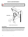
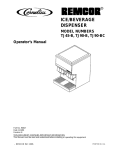
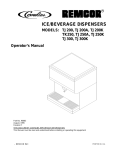
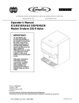
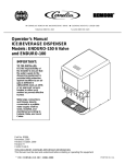
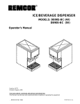
ICE/BEVERAGE DISPENSERS
MODELS: TJ45--A, TJ45--AB
TJ90--A, TJ90--AB,
TJ90--ABC
WITH AUTOMATIC ICE FILLING FROM A REMOTE ICEMAKER SOURCE
Operator’s Manual
Part No. 90632
Revision H
Revised March 21, 1996
THIS DOCUMENT CONTAINS IMPORTANT INFORMATION
This Manual must be read and understood before installing or operating this equipment
â REMCOR INC:
PRINTED IN U.S.A
TABLE OF CONTENTS
Page
SAFETY PRECAUTIONS . . . . . . . . . . . . . . . . . . . . . . . . . . . . . . . . . . . . . . . . . . . . . . . . . . .
DESCRIPTION . . . . . . . . . . . . . . . . . . . . . . . . . . . . . . . . . . . . . . . . . . . . . . . . . . . . . . . . . . . .
INSTALLATION INSTRUCTIONS . . . . . . . . . . . . . . . . . . . . . . . . . . . . . . . . . . . . . . . . . . . .
SINK DRAIN ASSEMBLY . . . . . . . . . . . . . . . . . . . . . . . . . . . . . . . . . . . . . . . . . . . . . . .
CLEANING INSTRUCTIONS . . . . . . . . . . . . . . . . . . . . . . . . . . . . . . . . . . . . . . . . . . . . . . . .
DISPENSER . . . . . . . . . . . . . . . . . . . . . . . . . . . . . . . . . . . . . . . . . . . . . . . . . . . . . . . . . .
COLD PLATE WHEN REQUIRED . . . . . . . . . . . . . . . . . . . . . . . . . . . . . . . . . . . . . . .
BEVERAGE SYSTEM (WHEN REQUIRED) . . . . . . . . . . . . . . . . . . . . . . . . . . . . . .
OPERATING INSTRUCTIONS . . . . . . . . . . . . . . . . . . . . . . . . . . . . . . . . . . . . . . . . . .
SERVICE AND MAINTENANCE . . . . . . . . . . . . . . . . . . . . . . . . . . . . . . . . . . . . . . . . . . . . .
ADJUSTMENTS . . . . . . . . . . . . . . . . . . . . . . . . . . . . . . . . . . . . . . . . . . . . . . . . . . . . . . .
TROUBLESHOOTING GUIDE . . . . . . . . . . . . . . . . . . . . . . . . . . . . . . . . . . . . . . . . . . . . . . .
BLOWN FUSE OR CIRCUIT BREAKER . . . . . . . . . . . . . . . . . . . . . . . . . . . . . . . . . .
GATE DOES NOT OPEN. AGITATOR DOES NOT TURN. . . . . . . . . . . . . . . . . . .
GATE DOES NOT OPEN OR IS SLUGGISH. AGITATOR TURNS. . . . . . . . . . . .
GATE OPENS. AGITATOR DOES NOT TURN. . . . . . . . . . . . . . . . . . . . . . . . . . . . .
ICE DISPENSES CONTINUOUSLY. . . . . . . . . . . . . . . . . . . . . . . . . . . . . . . . . . . . . . .
SLUSHY ICE. WATER IN HOPPER . . . . . . . . . . . . . . . . . . . . . . . . . . . . . . . . . . . . . .
ICE SOLIDIFIED IN HOPPER, OR ICE AT REAR CORNER ONLY. . . . . . . . . . . .
NO ICE IN HOPPER . . . . . . . . . . . . . . . . . . . . . . . . . . . . . . . . . . . . . . . . . . . . . . . . . . .
ICE PACKED IN HOPPER. . . . . . . . . . . . . . . . . . . . . . . . . . . . . . . . . . . . . . . . . . . . . . .
BEVERAGES DO NOT DISPENSE . . . . . . . . . . . . . . . . . . . . . . . . . . . . . . . . . . . . . .
BEVERAGES TO SWEET. . . . . . . . . . . . . . . . . . . . . . . . . . . . . . . . . . . . . . . . . . . . . . .
BEVERAGES NOT SWEET ENOUGH. . . . . . . . . . . . . . . . . . . . . . . . . . . . . . . . . . . .
BEVERAGES NOT COLD (UNITS WITH BUILT-IN COLD PLATE) . . . . . . . . . . .
PARTS LIST . . . . . . . . . . . . . . . . . . . . . . . . . . . . . . . . . . . . . . . . . . . . . . . . . . . . . . . . . . . . . .
WARRANTY . . . . . . . . . . . . . . . . . . . . . . . . . . . . . . . . . . . . . . . . . . . . . . . . . . . . . . . . . . . . . .
1
2
3
3
4
4
4
4
5
6
6
7
7
7
7
7
7
7
7
7
7
7
7
7
7
18
20
LIST OF FIGURES
FIGURE 1. SINK DRAIN ASSEMBLY . . . . . . . . . . . . . . . . . . . . . . . . . . . . . . . . . . . . .
FIGURE 2. GATE RESTRICTOR PLATE . . . . . . . . . . . . . . . . . . . . . . . . . . . . . . . . . .
FIGURE 3. MOUNTING TEMPLATE . . . . . . . . . . . . . . . . . . . . . . . . . . . . . . . . . . . . .
FIGURE 4. TYPICAL POST-MIX BEVERAGE SYSTEM
SCHEMATIC “--B”DISPENSERS . . . . . . . . . . . . . . . . . . . . . . . . . . . . . . . . . . . . . . . .
FIGURE 5. TYPICAL POST-MIX BEVERAGE SYSTEM
SCHEMATIC “--BC”DISPENSERS . . . . . . . . . . . . . . . . . . . . . . . . . . . . . . . . . . . . . . .
FIGURE 6. INSTALLATION . . . . . . . . . . . . . . . . . . . . . . . . . . . . . . . . . . . . . . . . . . . . .
FIGURE 7. FIELD WIRING . . . . . . . . . . . . . . . . . . . . . . . . . . . . . . . . . . . . . . . . . . . . . .
FIGURE 8. DEFLECTOR ASSEMBLY . . . . . . . . . . . . . . . . . . . . . . . . . . . . . . . . . . . .
FIGURE 9. HOPPER INTERIOR . . . . . . . . . . . . . . . . . . . . . . . . . . . . . . . . . . . . . . . . .
FIGURE 10. WIRING DIAGRAM TJ45, 90-A DISPENSER
SERVICE INFORMATION . . . . . . . . . . . . . . . . . . . . . . . . . . . . . . . . . . . . . . . . . . . . . . .
FIGURE 11 UPPER SECTION EXPLODED VIEW TJ45 . . . . . . . . . . . . . . . . . . . .
FIGURE 12 EXPLODED VIEW LOWER SECTION TJ45 . . . . . . . . . . . . . . . . . . . .
FIGURE 13 EXPLODED VIEW UPPER SECTION TJ90 . . . . . . . . . . . . . . . . . . . .
FIGURE 14 EXPLODED VIEW LOWER SECTION TJ90 . . . . . . . . . . . . . . . . . . . .
FIGURE 15. SOLENOID ASSEMBLY . . . . . . . . . . . . . . . . . . . . . . . . . . . . . . . . . . . . .
i
3
6
8
9
10
11
11
12
12
13
14
15
16
17
19
90632
SAFETY PRECAUTIONS
Always disconnect power to the dispenser before servicing or cleaning.
Never place hands inside of hopper or gate area without disconnecting power to the dispenser. Agitator rotation
occurs automatically when dispenser is energized.
This ice dispenser has been specifically designed to provide protection against personal injury and eliminates
contamination of ice. To insure continued protection and sanitation, observe the following:
1. ALWAYS be sure the removable lid is properly installed to prevent unauthorized access to the hopper
interior and possible contamination of the ice.
2. ALWAYS be sure the upper and lower front panels are securely fastened.
3. ALWAYS
keep area around the dispenser clean of ice cubes.
CAUTION: Dispenser cannot be used with crushed of flaked ice.
Use of bagged ice which has frozen into large chunks can void warranty. The dispenser
agitator is not designed to be an ice crusher. Use of large chunks of ice which “jam up” inside the
hopper will cause failure of the agitator motor and damage to the hopper. If bagged ice is used, it
must be carefully and completely broken into small, cub-sized pieces before filling into the
dispenser hopper
1
90632
DESCRIPTION
The REMCORâ Ice and Ice/Beverage dispensers with model numbers suffixed with--A, --AB, and --ABC (e.g.
model TJ90E--ABC) are designed to be used with one of several remote “piped ice”type machine. This combination automatically provides a continuous supply of sanitary ice at the touch of a lever, In order to complete
an automatic filling installation, the following items must be obtained.
1. Icemaker. This must be obtained from the appropriate manufacturer.
2. Feed Tube Kit This kit contains parts and instructions necessary to connect the ice machine to the ice dispenser. Be sure the feed tube kit is proper for your icemaker. The following tube kits are approved for use
on the TJ45/90--A dispensers:
Kit No.
1913
1922
1923
1924
Icemaker
Reynolds
Reynolds
Jeito
Scotsman
90632
2
Model
CF--3--TT
CF--6--TT
MD700
EC900
INSTALLATION INSTRUCTIONS
1. The ice dispenser must be fastened and sealed to the counter, using the hardware supplied with the unit.
The template drawings (Figure NO TAG) indicate openings which must be cut in the counter for the ice
feed tube and utilities. Check that the counter mounting surface for the dispenser is level.
Apply a continuous bead of NSF approved silastic sealant (Dow 732 or equal) approximately 1/4”inside of
the unit outline dimensions, and around all openings. Then position the unit on the counter within the outline dimensions. Fasten the ice dispenser in place with mounting hardware provided. All excess sealant
must be wiped away immediately.
2. Position the icemaker and install the feed tube and other components according to the instruction supplied
with the feed tube kit.
3. Route the icemaker control bulb along the outside of the dispenser cabinet, and into the hopper as shown
in Figure 2. Install insulating tubing and mount the bulb to the deflector assembly as shown in Figure 5.
Use care when handling the bulb to avoid damaging or kinking it. Do not allow the bulb to contact any cold
surfaces, or false sensing will occur. Route the bulb away from electrical terminals, moving parts, or sharp
metal edges.
4. Permanently wire the dispenser to a source of 120V, 60Hz. power as shown in Figure 3. Wiring must conform to N.E.C. and local codes
5. On beverage units --AB, and -- ABC connect the beverage system product lines as indicated in Figures 4,
5, and 9. This work should be done by a qualified service person.
6. Connect the drain tube to an open drain. If additional piping is required, it must be 3/4”IPS (or equal) and
must continuously pitch downward away from the unit for proper drainage.
7. Complete the installation of the icemaker according to the instructions supplied with the unit and the markings on the icemaker itself.
SINK DRAIN ASSEMBLY
1. Use tube, clamp and insulation provided to assemble drain.
2. To assure proper drainage, do not allow “trap”to form in drain line. Be sure drain line runs flat with bottom
of dispenser (see Figure 1)
DRAIN LINE
DISPENSER BOTTOM
FIGURE 1. SINK DRAIN ASSEMBLY
3
90632
CLEANING INSTRUCTIONS
WARNING: Disconnect power before cleaning. Do not use metal scrapers, sharp objects or
abrasives on the surface of the liner, as damage may result. Do not use solvents or other
cleaning agents, as they may attack the plastic liner.
DISPENSER
1. Clean the ice dispenser interior at least once a month.
2. Lift off agitator assembly and wash and rinse it thoroughly.
3. Carefully remove and disassemble the deflector assembly and wash and rinse all parts.
4. Wash down the inside of hopper and top cover with mild detergent solution and rinse thoroughly to remove
all traces of detergent.
5. Replace agitator and deflector assembly, using care to reinstall the bulbs properly.
6. Sanitize the inside of hopper and agitator with a solution of 1 ounce of household bleach in 1 gallon of water.
7. With the brush provided, clean the inside of the ice chute with a mild detergent solution and rinse thoroughly to remove all traces of detergent. Sanitize as described in step 6.
COLD PLATE
when required
1. Carefully remove the lower front panel of the ice dispenser.
2. Remove cold plate cover by lifting slightly in front and slide forward.
3. Wash down the inside of the cold plate cabinet and cover with mild detergent solution and rinse. A small,
long-handled brush will be found helpful in reaching the corners.
4. Replace the cover, taking care that it is securely positioned in cold plate tray.
5. Replace and lower front panel, carefully feeding the tubes and wires into the cabinet. Be sure not to pinch
any tubing or wires between the panel and cabinet.
BEVERAGE SYSTEM
(when required)
1. Remove faucet spouts, wash in mild detergent, rinse and replace.
2. Disconnect electrical power to the carbonator. Shut off the water supply and close the CO2 regulator to the
carbonator.
3. Disconnect the syrup tanks from the system.
4. Energize the beverage faucets to purge the remaining soda water in the system.
5. Use a clean 5 gallon tank for each of the following:
A.
Cleaning Tank -- Fill with hot (120°-- 140°) potable water.
90632
4
B.
Sanitation Tank -- Fil with a chlorine sanitizing solution in the strength of 1 ounce of household bleach
(sodium hypochlorite) to 1 gallon of cold (ambient) potable water (410PPM).
6. Repeat the following procedure on each of the unit’s syrup product lines.
A.
Connect the cleaning tank to the syrup line to be sanitized and to the CO2 system.
B.
Energize the beverage faucet until the liquid dispensed is free of any syrup.
C.
Disconnect the cleaning tank and hook-up the sanitizing tank to the syrup line and CO2 system.
D.
Energize the beverage faucet until the chlorine sanitizing solution is dispensed through the faucet.
Flush at least 2 cups of liquid to insure that the sanitizing solution has filled the entire length of the
syrup line.
E.
Disconnect the sanitizing tank. Hook up the product tank to the syrup line and to the CO2 system.
F.
Energize the faucet to flush the sanitizing solution from the syrup line and faucet. Continue draw on
faucet until only syrup is dispensed.
7. Repeat Step 2 in reverse order to turn on the carbonator. Dispense at lease 1 cup of beverage from each
faucet. Check taste, continue to flush, if needed, to obtain satisfactory tasting drink.
OPERATING INSTRUCTIONS
1. ice Dispensing. Depressing the operating level activates a micro switch behind the front panel, Which energizes the agitator motor and gate solenoid. This causes the agitator to rotate and the gate slide to left, allowing ice to push out the gate opening.
2. Automatic Ice Filling. Two thermostatic capillary controls are utilized. The control capillary of the ice dispenser (agitation bulb) will activate the agitation timer as it senses ice. The agitation timer causes the ice to
level which allows the entire ice storage bin to fill before the ice machine shuts off. When the ice level remains at the deflector after agitation, the icemaker control capillary (icemaker bulb) stops icemaker operation until the level drops, and the bulbs warm up
While the icemaker is running, the ice entering the hopper from the feed tube should be loose and in small
pieces. Ice entering in the form of hard packed cylinders indicates a restriction or distortion of the feed
tube, and could result in icemaker malfunction of not corrected.
Immediately after icemaker shutoff, observe the ice in the hopper between the feed tube entrance and the
deflector. It should be loosely pressed against the top of the deflector, indicating correct thermostat operation. If the ice level is low, or if ice is packed hard against the deflector it will be necessary to readjust the
icemaker bin control, according to the icemaker instructions. (Adjust the control warmer to lower the ice
level, and colder to raise the ice level)
3. Beverage System. (--AB and --ABC models only) Beverages may be dispensed by operating the lever on
the appropriate faucets. On units with cold plates (--ABC), periodic movement of the ice in the hopper is
necessary to maintain the level of ice on the cold plate. On initial startup, of after long idle period with no
use, dispensing ice for 20--30 seconds is necessary to fill the cold plate, or warm beverages may be experienced.
5
90632
SERVICE AND MAINTENANCE
CAUTION: Disconnect power to dispenser before installing, removing or adjusting this kit.
INSTALL PLATE ON
STUDS AS SHOWN
FIGURE 2. GATE RESTRICTOR PLATE
ADJUSTMENTS
This dispenser is provided with a gate restrictor plate, installed in it highest position. This plate adjusts the rate
of ice flow from the dispenser. In applications using buckets, carafes or other large containers, the plate may be
removed entirely for maximum ice flow. For glasses and cups, the plate may be adjusted downward to reduce
the flow of ice. The best position depends on the type of ice being used and the size container and must be
found by trial and error. Adjustment is made by loosening the upper two ice chute retaining nuts, sliding the restrictor plate to the desired position and re-tightening the nuts.
90632
6
TROUBLESHOOTING GUIDE
Should your unit fail to operate properly, check that there is power to the unit and that the hopper contains ice. If
the unit still does not dispense, check the following chart under the appropriate symptoms to aid in locating the
defect.
Trouble
BLOWN FUSE OR CIRCUIT BREAKER.
A.
Probable Cause
Short circuit in wiring.
B.
Defective gate solenoid.
C.
A.
Defective agitator motor.
No power.
B.
Bent depressor plate (does not actuate
switch).
C.
A.
Defective dispensing switch.
Defective gate solenoid.
B.
Weak gate spring.
C.
A.
Excessive pressure against gate slide.
Ice solidified in hopper.
B.
Defective agitator motor.
C.
A.
Defective capacitor (TJ90 only).
Stuck or bent depressor plate (does not
release switch)
B.
Defective dispensing switch.
C.
A.
Improper switch installation.
Blocked drain.
B.
A.
Unit no level.
Defective or improperly adjusted thermostat.
NO ICE IN HOPPER
ICE PACKED IN HOPPER.
B.
A.
A.
BEVERAGES DO NOT DISPENSE.
A.
Defective agitation timer.
Icemaker malfunction.
Defective or improperly adjusted control (not
shutting off).
No 24 volt power to faucets.
BEVERAGES TOO SWEET.
B.
A.
No CO2 pressure.
Carbonator not working.
B.
No CO2 pressure in carbonator.
C.
A.
Faucet brix requires adjusting.
Empty syrup tank.
B.
A.
Faucet brix requires adjusting.
Unit standing with no ice use - no ice in cold
plate cabinet.
GATE DOES NOT OPEN. AGITATOR DOES NOT
TURN.
GATE DOES NOT OPEN OR IS SLUGGISH.
AGITATOR TURNS.
GATE OPENS. AGITATOR DOES NOT TURN.
ICE DISPENSES CONTINUOUSLY.
SLUSHY ICE. WATER IN HOPPER.
ICE SOLIDIFIED IN HOPPER, OR ICE AT REAR
CORNER ONLY.
BEVERAGES NOT SWEET ENOUGH.
BEVERAGES NOT COLD (UNITS WITH BUILT-IN
COLD PLATE).
NOTE: contact your local syrup or beverage equipment distributor for additional information and troubleshooting of beverage system.
7
90632
8
90632
1-1/8 IN
OUTLINE
OF UNIT
1- 1/4 IN
1- 1/8 IN
2 -1/8-DIA.
10- 5/8 IN
6- 17/ 32 IN.
2- 5/16-IN.
5/8 IN.
8*
22-IN.
19-3/4 IN
TJ90--AB, ABC
18- 7/8-IN.
2*
4-IN.
FIGURE 3. MOUNTING TEMPLATE
15 7/8-IN.
12-5/8 IN
TJ45--AB
9-3/4 IN
2*
1-5/8 IN
1-5/8 IN
OUTLINE
OF UNIT
18-9/16-IN.
NOTE: 1)SHADED AREA INDICATE OPENINGS IN CABINET
BOTTOM NEEDED FOR UTILITIES AND BEVERAGE
TUBING.
2) * INDICATES 1/2” DIA. ACCESS HOLE FOR
ICEMAKER CONTROL BULB.
3/8 DIA
3 PLACES
21 -25/32-IN.
3/4 IN
27- 23/32-IN.
3/8 DIA
3 PLACES
16-1/4 IN
4- 1/2-IN.
5/8-IN.
1-1/8 IN
3/4-IN.
7-1/2-IN.
9
90632
CW
CW
8
7
6
5
4
3
2
1
REMCPR “--B” ICE/BEVERAGE DISPENSER
ITEMS OUTSIDE OF BROKEN LINES NOT
INCLUDED WITH UNIT.
FAUCETS
5--15
PSIG
S2
S3
S6
60-100 PSIG
S5
CARBONATOR
S4
15--50 PSIG
SYRUP
TANKS
S8
REGULATOR
NOTE:
FOR REFERENCE ONLY -- NOT
FOR CONTRUCTION.
CO2 TANK
WATER
SUPPLY
OPTIONAL
PRESSURE REGULATOR
FILTER
S7
FIGURE 4. TYPICAL POST-MIX BEVERAGE SYSTEM
SCHEMATIC “--B” DISPENSERS
COLD PLATE OR
REFRIGERATED
ICE BANK
S1
OPTIONAL FOR DIET OR ROOT BEER
10
90632
COLD PLATE
CW
CW
8
7
6
5
4
3
2
1
REMCPR “--B” ICE/BEVERAGE DISPENSER
ITEMS OUTSIDE OF BROKEN LINES NOT
INCLUDED WITH UNIT.
FAUCETS
5--15
PSIG
S2
S3
S6
60-100 PSIG
S5
CARBONATOR
S4
15--50 PSIG
SYRUP
TANKS
S8
REGULATOR
NOTE:
FOR REFERENCE ONLY -- NOT
FOR CONTRUCTION.
CO2 TANK
WATER
SUPPLY
OPTIONAL
PRESSURE REGULATOR
FILTER
S7
FIGURE 5. TYPICAL POST-MIX BEVERAGE SYSTEM
SCHEMATIC “--BC” DISPENSERS
COLD PLATE OR
REFRIGERATED
ICE BANK
S1
OPTIONAL FOR DIET OR ROOT BEER
FIGURE 6. INSTALLATION
ROUTE ICEMAKER
BULB AS SHOWN
FASTEN & SEAL
TO COUNTER
ELECTRIC
CONDUIT
DISPENSER
DISPENSER
DRAIN
ICEMAKER
ICEMAKER
SEE INSTALLATION KIT INSTRUCTION FOR FEED TUBE DETAILS
FIGURE 7. FIELD WIRING
FIELD WIRING
COMPARTMENT
LOWER CABINET
GRND.
BLK.
WHT.
NEUTRAL
HOT
FIELD SUPPLY CONDUIT
11
90632
STAINLESS
DEFLECTOR
ICEMAKER
BULB -- TOP
AGITATION
BULB -BOTTOM
END OF INSTALLED
BULB PROTRUDES
APPROX 1/4” TYPICAL
ALUMINUM
PLATE
FIGURE 8. DEFLECTOR ASSEMBLY
DEFLECTOR ASSEMBLY
INSTALL BARE BULBS
AS SHOWN ABOVE
AGITATION BULB
ICEMAKER BULB
WITH INSULATION
TUBING UP TO
DEFLECTOR
INSULATING TUBING
UP TO DEFLECTOR
FIGURE 9. HOPPER INTERIOR
90632
12
DANGER: ELECTRIC SHOCK HAZARD DISCONNECT
POWER BEFORE SERVICING UNIT
GRN.
L N
WHT.
GRD.
* T’STAT IS SHOWN IN
WARM POSITION.
GATE
SOL.
“OFF”
“ON”
MOTOR HEATER
1-1/4 AMP TIME
DELAY FUSE.
BLK
WHT
INPUT
3
COLD PLATE
MOTOR OPTION
2
WHT
C
B
L
U
1
T’STAT*
NO
NC
CAP.
R
E
D
BLK
AGITATION TIMER
R
E
D
WHT
LID SWITCH
(LID SCREW MUST BE
IN PLACE FOR AGITATOR OPERATION)
WHT
BLK
BLK
RD
RED
TERMINAL
BOARD
TRANS.
R
E
D
B AGITATOR
L
MOTOR
U
E
24V.
KEY
SWITCH
OPTION
CAP.
(TJ 90 ONLY)
BEVERAGE
FAUCET
TYPICAL
DISPENSE
SWITCH
BLK
TD
BEVERAGE SYSTEM
PORTION
CONTROL
OPTION
TO
TERMINAL
BOARD
SOLENOID ADJUSTMENT
WHT
SW
PORTION
TIMER
OR
DISPENSE
SWITCH
RED
RED
BLK
7/8 WHEN REPLACING SOLENOID
ADJUST TO 7/8 AS SHOWN
BEFORE TIGHTENING MOUNTING
SCREWS
FIGURE 10. WIRING DIAGRAM TJ45, 90-A DISPENSER
SERVICE INFORMATION
13
90632
4
22
24
12
10
11
9
1
18
26
28
2
15
14
23
15
27
FIGURE 11 UPPER SECTION EXPLODED VIEW TJ45
8
16
5
3
20
6
7
13
FIGURE 12 EXPLODED VIEW LOWER SECTION TJ45
90632
14
22
4
12
18
26
14
10
11
21
1
15
28
9
23 15
8
17
2
27
FIGURE 13 EXPLODED VIEW UPPER SECTION TJ90
16
5
3
20
13
6
7
FIGURE 14 EXPLODED VIEW LOWER SECTION TJ90
15
90632
PARTS LIST
Item No.
Part No. TJ45
-A -AB
Part No. TJ90
-A, -AB, -ABC
1
21491
21491
Gate Slide
2
30528
30528
Interlock Switch
3
21515
21515
Depressor Lever
4
21948
21932
Agitator (-A, -AB Models Only)
----------
21958
Agitator (-ABC Models Only)
5
30895
30895
Dispense Switch
Description
6
31007
31007
Switch Boot
7
31163
31163
Switch Insert
8
31091
31091
Transformer
9
31106
31112
Agitator Motor
10
50454
50454
Motor Shaft Seal
11
50481
50806
Motor Gasket
12
50800
50801
Lid
13
50750
50793
Sink (-A, -AB, Models Only)
----------
51019
14
53015
53015
53016
53016
Ice Chute Cover
15
50770
50770
Gate Gasket
Sink Grill
(-ABC Models Only)
Ice Chute Back Section
16
70426
70441
17
----------
30774
Capacitor
18
31093
31093
Solenoid Assembly
19
70438
70438
Rebuilding Kit
20
22644
22644
Depressor Retainer
21
----------
30794
Agitation Motor Heater (ABC Models Only)
22
21575
21575
Deflector Assy
23
21929
21929
Ice Cutter
24
21934
----------
Ice Level Rod
25
----------
22081
Gate Restrictor
26
23062
23062
Foam Shield
27
31290
31290
Agitation Timer
28
31001
31001
Thermostat
90632
16
1
2
22
4
3
5
4
22
6
19
18
22
20
21
8
16
15
14
11
10
17
19
13
9
12
7
FIGURE 15. SOLENOID ASSEMBLY
Index
No.
Part No.
Qty.
Name
1
21493
1
2#
31551
1
Solenoid Mounting Plate
Solenoid Service Kit
3
70171
2
8--32 x 3/8 Phil Tr HD Screw
4
70121
2
No. 8 Lockwasher
5
50752
3
Isolator
6*
50789
2
Bumper Assembly
7*
70423
1
Cotter Pin
8*
10080
1
Gate Lift Rod
9
10081
1
Gate Lift Rod Bushing
10
50754
1
Gate Arm Bearing
Gate lift Arm
11
21492
1
12
70043
1
Flatwasher
13*
70422
1
Spring
14
70263
1
1/4-20 x 3/4 Hex Hd Screw
15
70048
1
1/4 Lockwasher
16
70066
1
1/4 Flatwasher
17
10077
1
Pivot Bearing
18
30227
1
1/4 Quick Connect Tab
19
50305
----
Lubricant
20*
21592
1
Solenoid Linkage Pin
21*
70433
2
Retainer Ring
22
51088
----
Loctite
----*
70438
----
Rebuilding Kit
NOTE: * Parts supplied with rebuilding kit.
# 31551 solenoid supplied with items 20 & 21.
17
90632
IMI CORNELIUS INC.
ONE CORNELIUS PLACE
ANOKA, MN. 55303--6234
TELEPHONE (800) 238--3600
FACSIMILE (612) 422--3232
TECH SVC 1-800-535-4240
WARRANTY
IMI Cornelius Inc. and Remcor Products Company warrants that all equipment and parts are free from defects
in material and workmanship under normal use and service. For a copy of the warranty applicable to your
Cornelius and or Remcor product, in your country, please write, fax or telephone the IMI Cornelius office nearest you. Please provide the equipment model number, serial number and the date of purchase.
IMI Cornelius Offices
AUSTRALIA D P.O. 210, D RIVERWOOD, D NSW 2210, AUSTRALIA D (61) 2 533 3122 D FAX (61) 2 534 2166
AUSTRIA D AM LANGEN FELDE 32 D A-1222 D VIENNA, AUSTRIA D (43) 1 233 520 D FAX (43) 1-2335-2930
BELGIUM D BOSKAPELLEI 122 D B-2930 BRAASCHAAT, BELGIUM D (32) 3 664 0552 D FAX (32) 3 665 2307
BRAZIL D RUA ITAOCARA 97 D TOMAS COELHO D RIO DE JANEIRO, BRAZIL D (55) 21 591 7150 D FAX (55) 21 593 1829
ENGLAND D TYTHING ROAD ALCESTER D WARWICKSHIRE, B49 6 EU, ENGLAND D (44) 789 763 101 D FAX (44) 789 763 644
FRANCE D 71 ROUTE DE ST. DENIS D F-95170 DEUIL LA BARRE D PARIS, FRANCE D (33) 1 34 28 6200 D FAX (33) 1 34 28 6201
GERMANY D CARL LEVERKUS STRASSE 15 D D-4018 LANGENFELD, GERMANY D (49) 2173 7930 D FAX (49) 2173 77 438
GREECE D 488 MESSOGION AVENUE D AGIA PARASKEVI D 153 42 D ATHENS, GREECE D (30) 1 600 1073 D FAX (30) 1 601 2491
HONG KONG D 1104 TAIKOTSUI CENTRE D 11-15 KOK CHEUNG ST D TAIKOKTSUE, HONG KONG D (852) 789 9882 D FAX (852) 391 6222
ITALY D VIA PELLIZZARI 11 D 1-20059 D VIMARCATE, ITALY D (39) 39 608 0817 D FAX (39) 39 608 0814
NEW ZEALAND D 20 LANSFORD CRES. D P.O. BOX 19-044 AVONDALE D AUCKLAND 7, NEW ZEALAND D (64) 9 8200 357 D FAX (64) 9 8200 361
SINGAPORE D 16 TUAS STREET D SINGAPORE 2263 D (65) 862 5542 D FAX (65) 862 5604
SPAIN D POLIGONO INDUSTRAIL D RIERA DEL FONOLLAR D E-08830 SANT BOI DE LLOBREGAT D BARCELONA, SPAIN D (34) 3 640 2839 D FAX (34) 3 654 3379
USA D ONE CORNELIUS PLACE D ANOKA, MINNESOTA D (612) 421-6120 D FAX (612) 422-3255
18
Manual number
IMI CORNELIUS INC.
Corporate Headquarters:
One Cornelius Place
Anoka, Minnesota 55303-6234
Telephone (800) 238-3600
Facsimile (612) 422-3246