1
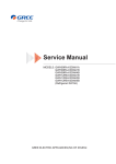
Service Manual
02'(/6 A16EM4H4R36
A16CI4H4R36
7DEOHRI&RQWHQWV
7DEOHRI&RQWHQWV
6XPPDU\DQG)HDWXUHV
6DIHW\3UHFDXWLRQV
6SHFL¿FDWLRQV
8QLW6SHFL¿FDWLRQV
2SHUDWLRQ&KDUDFWHULVWLF&XUYH
&DSDFLW\9DULDWLRQ5DWLRaFFRUGLQJWR7HPSHUDWXUH
2SHUDWLRQ'DWD
1RLVH&ULWHULD&XUYH7DEOHVIRUbRWK0RGHOV
&RQVWUXFWLRQ9LHZV
,QGRRU8QLW
2XWGRRU8QLW
5HIULJHUDQW6\VWHP'LDJUDP
6FKHPDWLF'LDJUDP
(OHFWULFDO:LULQJ
3ULQWHG&LUFXLW%RDUG
)XQFWLRQDQG&RQWURO
5HPRWH&RQWURO2SHUDWLRQV
'HVFULSWLRQRI(DFK&RQWURO2SHUDWLRQ
,QVWDOODWLRQ0DQXDO
1RWLFHVIRU,QVWDOODWLRQ
,QVWDOODWLRQ'LPHQVLRQ'LDJUDP
,QVWDOO,QGRRU8QLW
,QVWDOO2XWGRRU8QLW
&KHFNDIWHU,QVWDOODWLRQDQG2SHUDWLRQ7HVW
,QVWDOODWLRQDQG0DLQWHQDQFHRI+HDOWK\)LOWHU
7DEOHRI&RQWHQWV
([SORGHG9LHZVDQG3DUWV/LVW
,QGRRU8QLW
2XWGRRU8QLW
7URXEOHVKRRWLQJ
0DOIXQFWLRQ$QDO\VLV
)ODVKLQJ/('RI,QGRRU2XWGRRU8QLWDQG3ULPDU\-XGJHPHQW
+RZWRSimply &KHFNWKH0DLQ3DUW
5HPRYDO3URFHGXUH
5HPRYDO3URFHGXUHRI,QGRRU8QLW
5HPRYDO3URFHGXUHRI2XWGRRU8QLW
6XPPDU\DQG)HDWXUHV
6XPPDU\DQG)HDWXUHV
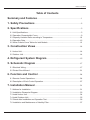
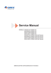
,QGRRU8QLW
2XWGRRU8QLW
5HPRWH&RQWUROOHU
<%))
FAN AUTO
OPER
AIR HEALTH X-FAN
HUMIDITY
FILTER
TURBO
HOUR
ON/OFF
ON/OFF
MODE
FAN
X-FAN
TEMP
TIMER
TURBO
SLEEP
LIGHT
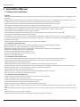
6DIHW\3UHFDXWLRQV
6DIHW\3UHFDXWLRQV
Installing, starting up, and servicing air conditioner can be
hazardous due to system pressure, electrical components,
and equipment location, etc.
Only trained, qualified installers and service personnel are
allowed to install, start-up, and service this equipment.
Untrained personnel can perform basic maintenance functions such as cleaning coils. All other operations should
be performed by trained service personnel.
Make sure the outdoor unit is installed on a stable, level
surface with no accumulation of snow, leaves, or trash
beside.
When handling the equipment, observe precautions in the
manual and on tags, stickers, and labels attached to the
equipment. Follow all safety codes. Wear safety glasses
andwork gloves. Keep quenching cloth and fire extinguisher
nearby when brazing.
Follow all the installation instructions to minimize the risk
of damage from earthquakes, typhoons or strong winds.
Read the instructions thoroughly and follow all warnings or
cautions in literature and attached to the unit. Consult local
building codes and current editions of national as well as
local electrical codes.
Recognize the following safety information:
Warning
Incorrect handling could result in
personal injury or death.
Caution
Incorrect handling may result in
minor injury,or damage to product
or property.
Warning
All electric work must be performed by a licensed technician
according to local regulations and the instructions given in
this manual.
Before installing, modifying, or servicing system, main
electrical disconnect switch must be in the OFF position.
There may be more than 1 disconnect switch. Lock out
and tag switch with a suitable warning label.
Never supply power to the unit unless all wiring and tubing are completed, reconnected and checked.
This system adopts highly dangerous electrical voltage.
Incorrect connection or inadequate grounding can cause
personal injury or death. Stick to the wiring diagram and
all the instructions when wiring.
Have the unit adequately grounded in accordance with
local electrical codes.
Have all wiring connected tightly. Loose connection may
lead to overheating and a possible fire hazard.
All installation or repair work shall be performed by your dealer or a specialized subcontractor as there is the risk of fire,
electric shock, explosion or injury.
Make sure the ceiling/wall is strong enough to bear the
weight of the unit.
Make sure the noise of the outdoor unit does not disturb
neighbors.
Avoid contact between refrigerant and fire as it generates
poisonous gas.
Apply specified refrigerant only. Never have it mixed with
any other refrigerant. Never have air remain in the
refrigerant line as it may lead to rupture and other hazards.
Make sure no refrigerant gas is leaking out when installation is completed.
Should there be refrigerant leakage, the density of refrigerant in the air shall in no way exceed its limited value,
or it may lead to explosion.
Keep your fingers and clothing away from any moving
parts.
Clear the site after installation. Make sure no foreign objects are left in the unit.
Always ensure effective grounding for the unit.
Caution
Never install the unit in a place where a combustible gas
might leak, or it may lead to fire or explosion.
Make a proper provision against noise when the unit is
installed at a telecommunication center or hospital.
Provide an electric leak breaker when it is installed in a
watery place.
Never wash the unit with water.
Handle unit transportation with care. The unit should not
be carried by only one person if it is more than 20kg.
Never touch the heat exchanger fins with bare hands.
Never touch the compressor or refrigerant piping without
wearing glove.
Do not have the unit operate without air filter.
Should any emergency occur, stop the unit and disconnect the power immediately.
Properly insulate any tubing running inside the room to
prevent the water from damaging the wall.
6SHFL¿FDWLRQV
0RGHO
3URGXFW&RGH
5DWHG9ROWDJH
3RZHU
5DWHG)UHTXHQF\
6XSSO\
3KDVHV
3RZHU6XSSO\0RGH
&RROLQJ&DSDFLW\ 0LQ ̚ 0D[
+HDWLQJ&DSDFLW\ 0LQ ̚ 0D[
&RROLQJ3RZHU,QSXW 0LQ ̚ 0D[
+HDWLQJ3RZHU,QSXW 0LQ ̚ 0D[
&RROLQJ3RZHU&XUUHQW
+HDWLQJ3RZHU&XUUHQW
5DWHG,QSXW
5DWHG&XUUHQW
$LU)ORZ9ROXPH 6++0/6/ 'HKXPLGLI\LQJ9ROXPH
((5
&23
6((5
+63)
$SSOLFDWLRQ$UHD
0RGHORILQGRRUXQLW
)DQ7\SH
'LDPHWHU/HQJWK ';/ )DQ0RWRU&RROLQJ6SHHG 6++0/6/ )DQ0RWRU+HDWLQJ6SHHG 6++0/6/ 2XWSXWRI)DQ0RWRU
)DQ0RWRU5/$
)DQ0RWRU&DSDFLWRU
,QSXWRI+HDWHU
(YDSRUDWRU)RUP
3LSH'LDPHWHU
,QGRRU
5RZ¿Q*DS
8QLW
&RLO/HQJWK /;';: 6ZLQJ0RWRU0RGHO
2XWSXWRI6ZLQJ0RWRU
)XVH
6RXQG3UHVVXUH/HYHO 6++0/6/ 6RXQG3RZHU/HYHO 6++0/6/ 'LPHQVLRQ :;+;' 'LPHQVLRQRI&DUWRQ%R[ /;:;+
'LPHQVLRQRI3DFNDJH /;:;+
1HW:HLJKW
*URVV:HLJKW
9̚
+]
%WXK
%WXK
:
:
$
$
:
$
&)0
3LQWK
%WXZK
%WXZK
%WXZK
%WXZK
VTIW
LQFK
UPLQ
UPLQ
:
$
ȝ)
:
LQFK
LQFK
LQFK
:
$
G% $ G% $ LQFK
LQFK
LQFK
OE
OE
*:+/%''1$$
&%
2XWGRRU
a
a
a
a
*:+/%''1$$,
&URVVÀRZ
ĭ;;
$OXPLQXP)LQFRSSHU7XE H
ĭ
;;
03%$
;;
;;
;;
6SHFL¿FDWLRQV
0RGHORI2XWGRRU8QLW
0,768%,6+,(/(&75,&
&RPSUHVVRU0DQXIDFWXUHU7UDGHPDUN
&RPSUHVVRU0RGHO
&RPSUHVVRU2LO
&RPSUHVVRU7\SH
/5$
&RPSUHVVRU5/$
&RPSUHVVRU3RZHU,QSXW
2YHUORDG3URWHFWRU
7KURWWOLQJ0HWKRG
2SHUDWLRQWHPS
$PELHQWWHPS FRROLQJ
$PELHQWWHPS KHDWLQJ
&RQGHQVHU)RUP
3LSH'LDPHWHU
5RZV¿Q*DS
&RLO/HQJWK /;';: )DQ0RWRU6SHHG
2XWSXWRI)DQ0RWRU
2XWGRRU
)DQ0RWRU5/$
8QLW
)DQ0RWRU&DSDFLWRU
$LU)ORZ9ROXPHRI2XWGRRU8QLW
)DQ7\SH
)DQ'LDPHWHU
'HIURVWLQJ0HWKRG
&OLPDWH7\SH
,VRODWLRQ
0RLVWXUH3URWHFWLRQ
3HUPLVVLEOH([FHVVLYH2SHUDWLQJ3UHVVXUH
IRUWKH'LVFKDUJH6LGH
3HUPLVVLEOH([FHVVLYH2SHUDWLQJ3UHVVXUH
IRUWKH6XFWLRQ6LGH
6RXQG3UHVVXUH/HYHO +0/ 6RXQG3RZHU/HYHO +0/ 'LPHQVLRQ :;+;' 'LPHQVLRQRI&DUWRQ%R[ /;:;+
'LPHQVLRQRI3DFNDJH /;:;+
1HW:HLJKW
*URVV:HLJKW
5HIULJHUDQW
5HIULJHUDQW&KDUJH
/HQJWK
*DV$GGLWLRQDO&KDUJH
&RQQHFWLRQ2XWHU'LDPHWHU/LTXLG3LSH
2XWHU'LDPHWHU*DV3LSH
3LSH
0D['LVWDQFH+HLJKW
0D['LVWDQFH/HQJWK
*8$1*=+28 &2035(6625
$
$
:
R
)
)
R
)
R
LQFK
LQFK
LQFK
USP
:
$
ȝ)
&)0
LQFK
&2/7'0,768%,6+,
71%)3*0&
)96
5RWDU\
&6)+
&DSLOODU\
a
a
a
$OXPLQXP)LQFRSSHU7XEH
ĭ
;;
$[LDOÀRZ
ĭ
$XWRPDWLF'HIURVWLQJ
7
,
,3
36,
36,
G% $ G% $ LQFK
LQFK
LQFK
OE
OE
;;
;;
;;
5$
ĭ
ĭ
R]
IW
R]IW
LQFK
LQFK
IW
IW
7KHDERYHGDWDLVVXEMHFWWRFKDQJHZLWKRXWQRWLFH3OHDVHUHIHUWRWKHQDPHSODWHRIWKHXQLW
6SHFL¿FDWLRQV
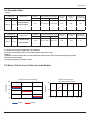
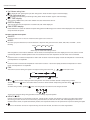
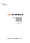
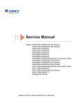
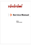
2SHUDWLRQ&KDUDFWHULVWLF&XUYH
+HDWOLQJ
18
18
16
16
14
14
12
12
Current(A)
Current(A)
&RROLQJ
10
8
8
Condition
Indoor:DB68 F WB62.6 F
Indoor air flow:high
Pipe length:25ft.
O
6
4
15
10
25
35
45
Compressor Speed (rps)
55
Condition
Indoor:DB68 F
Indoor air flow:high
Pipe length:25ft.
O
O
65
70
6
4
25
35
45
55
65
Compressor Speed (rps)
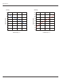
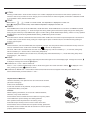
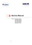
6SHFL¿FDWLRQV
+HDWOLQJ
120
120
110
110
100
100
Capacity ratio(%)
Capacity ratio(%)
&RROLQJ
90
80
70
90
80
70
60
60
50
50
40
90
95
100
Outdoor temp ̧
108
118
40
5
18
32
45
50
Outdoor temp ̧
6SHFL¿FDWLRQV
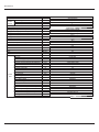
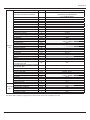
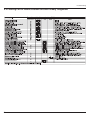
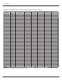
2SHUDWLRQ'DWD
&RROLQJ
7HPSHUDWXUH
FRQGLWLRQ R) ,QGRRU 2XWGRRU
0RGHOQDPH
A16EM4H4R36
A16CI4H4R36
6WDQGDUG
SUHVVXUH
3 03D +HDWH[FKDQJHUSLSHWHPS
R
R
7 ) 7 ) WR
WR
,QGRRUIDQ
PRGH
2XWGRRUIDQ &RPSUHVVRU
PRGH
UHYROXWLRQ USV
+LJK
+LJK
+HDWOLQJ
7HPSHUDWXUH
FRQGLWLRQ R) ,QGRRU 2XWGRRU
0RGHOQDPH
A16EM4H4R36
A16CI4H4R36
6WDQGDUG
SUHVVXUH
3 03D +HDWH[FKDQJHUSLSHWHPS
R
R
7 ) 7 ) WR
WR
,QGRRUIDQ
PRGH
2XWGRRUIDQ &RPSUHVVRU
PRGH
UHYROXWLRQ USV
+LJK
+LJK
72XWOHWDQGLQOHWSLSHWHPSHUDWXUHRIHYDSRUDWRU
72XWOHWDQGLQOHWSLSHWHPSHUDWXUHRIFRQGHQVHU
33UHVVXUHRIDLUSLSHXVHGIRUFRQQHFWLQJRXWGRRUDQGLQGRRUXQLWV
127(6
0HDVXUHVXUIDFHWHPSHUDWXUHRIKHDWH[FKDQJHUSLSHDURXQGFHQWHURIKHDWH[FKDQJHUSDWK8EHQW
7KHUPLVWRUWKHPRPHWHU
&RQQHFWLQJSLSLQJFRQGLWLRQIW
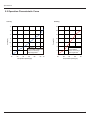
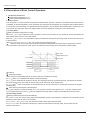
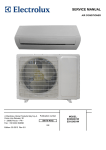
1RLVH&ULWHULD&XUYH7DEOHVIRUbRWK0RGHOV
Indoor side noise when blowing
Outdoor side noise when
Compressor speed changed
56
54
Noise/dB(A)
Noise/dB(A)
60
52
55
50
50
48
15
High
Middle
Cooling
Low
Heating
25
35
45
55
65 70
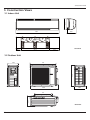
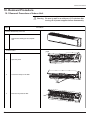
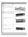
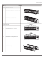
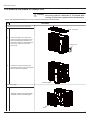
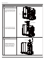
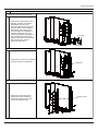
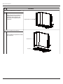
&RQVWUXFWLRQ9LHZV
&RQVWUXFWLRQ9LHZV
,QGRRU8QLW
8QLWLQFK
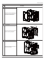
2XWGRRU8QLW
36
14.6
31.1
38.6
16.7
24
15.7
8QLWLQFK
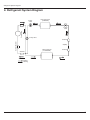
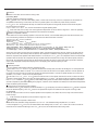
5HIULJHUDQW6\VWHP'LDJUDP
5HIULJHUDQW6\VWHP'LDJUDP
3-Way
valve
Heat exchanger
( INDOOR )
Compressor
Muffler
2-Way
valve
4-Way valve
Sub-accumulator
Strainer
Capillary
Strainer
Heat exchanger
( OUTDOOR )
Strainer
Cooling
Heating
6FKHPDWLF'LDJUDP
6FKHPDWLF'LDJUDP
(OHFWULFDO:LULQJ
(OHFWULFDO'DWD
,QGRRU8QLW
Symbo
Part name
Symbol
PROTECTIVE
EARTH
Color symbol
Symbol
Color symbol
BU
BLUE
BN
BROWN
YE
YELLOW
BK
BLACK
/
RD
RED
/
VT
VIOLET
YEGN
OG
YELLOW GREEN
ORANGE
2XWGRRU8QLW
Symbol
SAT
COMP
Parts name
Symbol
Color symbol
Symbol
Color symbol
OVERLOAD
BU
BLUE
VT
VIOLET
COMPRESSOR
YE
YELLOW
OG
ORANGE
PROTECTIVE EARTH
RD
RED
BN
BROWN
BK
YEGN
BLACK
YELLOW GREEN
,QGRRU8QLW
II
I
6FKHPDWLF'LDJUDP
2XWGRRU8QLW
2
3
COM
G
N.O
K101
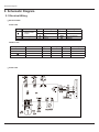
6FKHPDWLF'LDJUDP
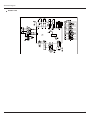
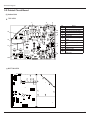
3ULQWHG&LUFXLW%RDUG
,QGRRU8QLW
TOP VIEW
1
2
3
4
13
5
6
12
11
1R
7
8
9
1DPH
7HUPLQDORIQHXWUDOZLUH
$XWREXWWRQ
7HUPLQDORIKRUL]RQWDOVZLQJ
7HUPLQDORIYHUWLFDOVZLQJ
&RPPXQLFDWLRQWHUPLQDO
-XPSHUFDS
7HUPLQDORIDPELHQWWHPS
VHQVRU
7HUPLQDORISLSHWHPSVHQVRU
7HUPLQDOVRIGLVSOD\SDQHO
DQG
2XWSXWWHUPLQDORIWUDQVIRUPHU
7HUPLQDORIOLYHZLUH
3URWHFWLYHWXEH
,QSXWWHUPLQDORI
WUDQVIRUPHU
10
BOTTOM VIEW
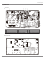
6FKHPDWLF'LDJUDP
2XWGRRU8QLW
TOP VIEW
1
2
3
4
5
6
7
8
9
10
12
1R
1DPH
+LJKIUHTXHQF\WUDQVIRUPHU7
7HUPLQDORIRYHUORDGSURWHFWLRQ
7HUPLQDORIWHPSVHQVRU
7HUPLQDORIKLJKSUHVVXUHSURWHFWLRQ
BOTTOM VIEW
1R
1DPH
7HUPLQDORIZD\YDOYH
&RPPXQLFDWLRQWHUPLQDO
7HUPLQDORIOLYHZLUH
7HUPLQDORIQHXWUDOZLUH
11
1R
1DPH
3URWHFWLYHWXEH)8
7HUPLQDORIJURXQGZLUH
&KRNH/DQG/
7HUPLQDORIRXWGRRUIDQ2)$1'&
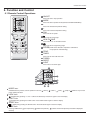
)XQFWLRQDQG&RQWURO
)XQFWLRQDQG&RQWURO
5HPRWH&RQWURO2SHUDWLRQV
1
)$1
$87 2
Press it to start or stop operation.
23(5
$,5 +($/ 7+ ;)$1
+80,',7<
2
MODE
Press it to select operation mode (AUTO/COOL/DRY/FAN/HEAT).
),/7(5
3
785%2
ON/OFF
Press it to decrease temperature setting.
+285
212))
4
+
Press it to increase temperature setting.
1
212))
2
02'(
3
5
Press it to set fan speed.
6
4
Press it to set swing angle.
7
5
6
)$1
7
9
;)$1
10
12 785%2 13
7(03
7,0(5
6/((3
/,*+7
FAN
HEALTH SAVE
Press it to turn on or off health function.
8
8
11
9
Press it to set left & right swing angle.
X-FAN(X-FAN is the alternative expression of BLOW for
the purpose of understanding.)
14
10
11
TEMP
TIMER
Press it to set timer ON/ timer OFF.
12
13
14
TURBO
SLEEP
LIGHT
Press it to turn on/off the light.
24
FAN
AUTO
OPER
AIR HEALTH X-FAN
HUMIDITY
15
16
17
18
15
FILTER
23
TURBO
HOUR
ON/OFF
22
21
19
20
MODE icon:
If MODE button is pressed, current operation mode icon
(AUTO),
( COOL),
(DRY),
(FAN) or
(HEAT is only for heat
pump models) will show.
16
LOCK icon:
17
LIGHT icon:
18
SLEEP icon :
is displayed by pressing "+" and “-” buttons simultaneously. Press them again to clear the display.
is displayed by pressing the LIGHT button. Press LIGHT button again to clear the display.
is displayed by pressing the SLEEP button. Press this button again to clear the display.
19
TEMP icon:
Pressing TEMP button,
circularly.
(set temperature),
(ambient temperature) ,
(outdoor ambient temperature) and blank is displayed
)XQFWLRQDQG&RQWURO
20
Up & down swing icon:
is displayed when pressing the up & down swing button. Press this button again to clear the display.
21
Left & right swing icon:
22
SET TIME display:
is displayed when pressing the left & right swing button.Press this button again to clear the display.
After pressing TIMER button, ON or OFF will blink.This area will show the set time.
23
DIGITAL display:
This area will show the set temperature. In SAVE mode,"SE" will be displayed.
24
FAN SPEED display:
Press FAN button to select the desired fan speed setting(AUTOLow-Med-High).Your selection will be displayed in the LCD windows,
except the AUTO fan speed.
Remote controller description
1
ON/OFF:
Press this button to turn on the unit. Press this button again to turn off the unit.
2
MODE:
Each time you press this button,a mode is selected in a sequence that goes from AUTO, COOL,DRY, FAN, and HEAT *, as the
following:
AUTO COOL DRY FAN
HEAT*
*Note: Only for models with heating function.
After energization, AUTO mode is defaulted. In AUTO mode, the set temperature will not be displayed on the LCD, and the unit will
automatically select the suitable operation mode in accordance with the room temperature to make indoor room comfortable.
3
+:
Press this button to increase set temperature. Hold it down for above 2 seconds to rapidly increase set temperature. In AUTO mode,
set temperature is not adjustable.
4
-:
Press this button to decrease set temperature. Hold it down for above . 2 seconds to rapidly decrease set temperature. In AUTO
mode, set temperature is not adjustable.
5
FAN :
This button is used for setting fan speed in the sequence that goes from AUTO,
,
,
to then back to Auto.
AUTO
Low speed
Medium speed
High speed
6
●Press
button to start or stop up & down swing function.The remote controller defaults to simple swing condition.
●Press + button and
button at the same time at unit OFF to switch between simple swing and static swing;
blinks for 2
seconds.
●In static swing condition, pressing
button, the swing angle of up & down louver changes as below:
OFF
●If the unit is turned off during swing operation,the louver will stop at present position.
7
HEALTH SAVE:
HEALTH function:there is no this function for this unit. If press this key, the main unit will click, but it also runs under original status.
Save energy function: this unit has no this function, press this button, the mian unit will click, "SE" will be displayed on the LCD of
wireless remote control, fan speed automatically rotates, when repress this button, the fan speed will run at previous setting fan speed.
8
There is no this function for this unit. If press this key, the main unit will click, but it also runs under original status.
)XQFWLRQDQG&RQWURO
9
X-FAN:
Pressing X -FAN button in COOL or DRY mode,the icon "X-FAN" is displayed and the indoor fan will continue operation for 10
minutes in order to dry the indoor unit even though you have turned off the unit. After energization, X-FAN OFF is defaulted. X-FAN
is not available in AUTO, FAN and HEAT mode.
10
TEMP:
When there is
When
11
,
or blank on remote control, set temperature is displayed on indoor unit.
is displayed on remote control, indoor ambient temperature is displayed on indoor unit.
TIMER:
Press TIMER button at unit ON to set TIMER OFF; HOUR OFF blinks. Press TIMER button at unit OFF to set TIMER ON; HOUR
ON blinks. In this case, pressing + or - button changes time setting. Holding down either button rapidly changes time setting (time
setting range 0.5-24hours). Press TIMER button again to confirm setting; HOUR ON/OFF stops blinking. If there is not any operation
of button within 5 seconds during HOUR ON/OFF blinking, TIMER setting will be cancelled.
12
TURBO:
Press this button to activate / deactivate the Turbo function which enables the unit to reach the preset temperature in shortest time.
In COOL mode, the unit will blow strong cooling air at super high fan speed. In HEAT mode, the unit will blow strong heating air
at super high fan speed.
13
SLEEP :
●Press this button, enter into SLEEP state,when repressed, it will quit. The sleep function will be canceled with the stop of the unit.
There is no SLEEP function under AUTO and FAN mode.
is the icon for sleepfunction.
●At COOL, DRY mode: the SLEEP mode runs after 1hour, the setting temp. will be increased by 1 ℃, 2 hour later, setting temp.
will be increased by 2℃ and then will run at this setting temperature.
●At HEAT mode: the SLEEP mode runs after 1hour, the setting temp will be decreased by1℃, 2 hours later setting temp. will be
decreased by2℃, then it will run.
14
LIGHT:
Press LIGHT button to turn on the display's light and press this button again to turn off the display's light. If the light is turned on ,
is displayed. If the light is tunrned off,
disappears.
15 Combination of "+" and "-" buttons: About lock
Press "+ " and " " buttons simultaneously to lock or unlock the keypad. If the remote controller is locked,
case, pressing any button,
is displayed. In this
blinks three times.
16 Combination of "MODE" and "-" buttons:About switch between Fahrenheit and Centigrade.At unit OFF, press "MODE" and "- "
buttons simultaneously to switch between ℃ and ℉ .
Replacement of Batteries
1.Remove the battery cover plate from the rear of the remote controller.
(As shown in the figure)
2.Take out the old batteries.
3.Insert two new AAA1.5V dry batteries, and pay attention to the polarity.
4. Reinstall the battery cover plate.
★Notes:
●When replacing the batteries, do not use old or different batteries,
otherwise, it may cause malfunction.
●If the wireless remote controller will not be used for a long time, please
remove batteries to prevent damage from leaking batteries.
●The operation should be performed in its receiving range.
●It should be kept 1m away from the TV set or stereo sound sets.
●If the wireless remote controller does not operate normally, please take
the batteries out and reinsert them after 30 seconds. If it still can't operate
properly, replace the batteries.
Sketch map for
replacing batteries
)XQFWLRQDQG&RQWURO
'HVFULSWLRQRI(DFK&RQWURO2SHUDWLRQ
1. Temperature Parameters
Indoor preset temperature (Tpreset)
Indoor ambient temperature (T amb.)
2. Basic Functions
Once energized, in no case should the compressor be restarted within less than 3 minutes. In the situation that memory function
is available, for the first energization, if the compressor is at stop before de-energization, the compressor will be started w ithout
a 3-minute lag; if the compressor is in operation before de-energization, the compressor will be started with a 3-minute lag; and
once started, the compressor will not be stopped within 6 minutes regardless of changes in room temperature;
(1) Cooling Mode
Working conditions and process of cooling
When T amb Tpreset, the unit will enter cooling operation, in which case the indoor fan, the outdoor fan and the compressor will
work and the indoor fan will run at preset speed.
When Tamb Tpreset -3.6 ºF , the compressor will stop, the outdoor fan will stop with a time lag of 60s, and the indoor fan will run
at preset speed.
When Tpreset -3.6 ºF < Tamb.< Tpreset +1.8 ºF , the unit will remain at its previous state.
Under this mode, the four-way valve will be de-energized and temperature can be set within a range from 61 to 86 ºF
If the compressor is shut down for some reason, the indoor fan and the swing device will operate at original state.
Tamb.
Start cooling
Tpreset
Original working state
Tpreset +3.6 ºF
Stop cooling
6 minutes
3 minutes
6 minutes
Compresso
r
Outdoor fan
Indoor fan
Preset fan speed
Run
Stop
Protection
Antifreeze protection
Under cooling and dehumidifying mode, 6 minutes after the compressor is started:
If T evap 35.6 ºF, the compressor will operate at reduced frequency.
If T evap 30.2 ºF is detected for durative 3 minutes, the compressor will stop, and after 60 seconds, the outdoor fan will stop;
and under cooling mode, the indoor fan and the swing motor will remain at the original state.
If T evap.
42.8 ºF and the compressor has remained at OFF for at least 3 minutes, the compressor will resume its original
operation state.
Total current up and frequency down protection
If Itotal 16A, frequency rise will be allowed; if Itotal 17A, frequency rise will not be allowed; if Itotal
run at reduced frequency; and if Itotal
18A, the compressor will
20A, the compressor will stop and the outdoor fan will stop with a time lag of 60s.
(2) Dehumidifying Mode
Working conditions and process of dehumidifying
If Tamb>Tpreset +1.8ºF, the unit will enter cooling and dehumidifying mode, in which case the compressor and the outdoor fan will
operate and the indoor fan will run at low speed.
If Tpreset -3.6 ºF Tamb Tpreset +1.8ºF, the compressor remains at its original operation state.
If Tamb.< Tpreset -3.6 ºF , the compressor will stop, the outdoor fan will stop with a time lag of 60s, and the indoor fan will
operate at low speed.
)XQFWLRQDQG&RQWURO
Protection
Protection is the same as that under the cooling mode.
(3) Heating Mode
Working conditions and process of heating
If Tamb. Tpreset +3.6 ºF, the unit enters heating mode, in which case the four-way valve, the compressor and the outdoor fan
will operate simultaneously, and the indoor fan will run at preset speed in the condition of preset cold air prevention.
If T amb. Tpreset +9 ºF, the compressor will stop, the outdoor fan will stop with a time lag of 60s, and the indoor fan will stop after
60- second blow at low speed
If Tpreset +3.6 ºF <T amb.< Tpreset +9 ºF, the unit will maintain its original operating status.
Under this mode, the four-way valve is energized and temperature can be set within a range of 61 - 86 ºF. The operating
symbol, the heating symbol and preset temperature are revealed on the display.
Condition and process of defrost
When duration of successive heating operation is more than 45 minutes, or accumulated heating time more than 90 minutes, and
one of the following conditions is reached, the unit will enter the defrost mode after 3 minutes.
A Toutdoor amb. 41̧, Toutdoor pipe 28.4̧;
B 28.4̧Toutdoor amb.
C 23̧Toutdoor amb.˘28.4̧, Toutdoor pipe17.6̧;
D 14̧Toutdoor amb.˘23̧, Toutdoor pipe- Tcompensation ˄Toutdoor amb-5.4̧˅˗
E Toutdoor amb.˘14̧, Toutdoor pipe-Tcompensation˄Toutdoor amb.-5.4̧˅
After energization, when defrosting for the first time Tcompensation=0̧. If it is not the firstly time for
defrosting, the Tcompensation is determined by the Toutdoor pipe of last time quitting defrosting.
a. Toutdoor pipe ˚35.6̧, Tcompensation=0̧; b. Toutdoor pipe 35.6̧, Tcompensation=5.4̧
At that time, the indoor fan stops and the compressor stops, and after 60 seconds the outer fan will stop, and then after 30
seconds, the four-way valve will stop. After 30 seconds, the compressor is initiated for raising the frequency to defrost frequ ency.
When the compressor has operated under defrost mode for 10 minutes, or T outer tube 50̧, the compressor will be converted to 46Hz
operation. After 30 seconds, the compressor will stop. And after another 30 seconds, the four-way valve will be opened, and af t er
60 seconds, the compressor and the outer fan will be started, the indoor fan will run under preset cold air prevention conditio ns,
and H1 will be displayed at temperature display area on the display panel. Defrost frequency is 70Hz.
3.Protection
Cold air prevention
The unit is started under heating mode (the compressor is ON):
In the case of T indoor amb. <75ºF : if T tube 104ºF and the indoor fan is at stop state, the indoor fan will begin to run at low speed with
a time lag of 2 minutes. Within 2 minutes, if T tube>104 ºF, the indoor fan also will run at low speed; and after 1-minute operation at
low speed, the indoor fan will be converted to operation at preset speed. Within 1-minute low speed operation or 2-minute nonoperation, if T tube>108ºF , the fan will run at present speed.
In the case of T indoor amb. 75 ºF : if T tube 108 ºF, the indoor fan will run at low speed, and after one minute, the indoor fan will be
converted to preset speed. Within one-minute low speed operation, if T tube>104 ºF , the indoor fan will be converted to preset speed.
Note: T
indoor amb.
indicated in
and
refers to, under initially heating mode, the indoor ambient temperature before the command to
start the compressor is performed according to the program, or after the unit is withdrawn from defrost, the indoor ambient temperature
before the defrost symbol is cleared.
Total current up and frequency down protection
If the total current Itotal 16A, frequency rise will be allowed; if Itotal
will run at reduced frequency; and if I total
17A,frequency rise will not be allowed; if Itotal
18A,the compressor
20A, the compressor will stop and the outdoor fan will stop with a time lag of 60s.
(4) Fan Mode
Under the mode, the indoor fan will run at preset speed and the compressor, the outdoor fan, the four-way valve and the electric
heater will stop.
Under the mode, temperature can be set within a range of 61 - 86 ºF .
(5) AUTO Mode
Working conditions and process of AUTO mode
Under AUTO mode, standard cooling temperature Tpreset is 77 º F and standard heating temperature T preset is 68 ºF .
a. Once energized, if Tamb 71.6 ºF, the unit will be started under heating mode; if 71.6ºF < Tamb.< 78.8 ºF, the unit will run under fan
mode and the run indicator will be bright; and if T amb 78.8 ºF , the unit will be started under cooling mode.
)XQFWLRQDQG&RQWURO
b.Under AUTO mode,if Tamb. Tpreset +1.8 ºF is detected,the unit will select to run under cooling mode,in which case implicit preset
temperature is 77 ºF ; if Tamb. Tpreset -1.8 ºF , the compressor will stop, the outdoor fan will stop with a time lag of 1 minute, and
the indoor fan will run at preset speed; and if T preset -1.8 ºF < Tamb.< Tpreset +1.8 ºF, the unit will remain at its original state.
c. Under AUTO mode, if Tamb. Tpreset + 3.6 ºF is detected, the unit will select to run under heating mode, in which case implicit
preset temperature is 64 ºF ; if Tamb. Tpreset +9 ºF , the compressor will stop, the outdoor fan will stop with a time lag of 1 minute,
and the indoor fan will run under the mode of residue heat blowing; and if Tpreset +3.6 ºF < Tamb.< Tpreset +41ºF, the unit will remain
atits original state. The cooling-only unit will run under fan mode.
d. Under AUTO mode, if 71.6 ºF< Tamb.< 78.8 ºF , the unit will remain at its original state.
Protection
a.
b.
In cooling operation, protection is the same as that under the cooling mode;
In heating operation, protection is the same as that under the heating mode;
c.
When ambient temperature changes, operation mode will be converted preferentially. Once started, the compressor will
remain unchanged for at least 6 minutes.
(6) Common Protection Functions and Fault Display under COOL, HEAT, DRY and AUTO Modes
Overload protection
T tube: measured temperature of outdoor heat exchanger under cooling mode; and measured temperature of indoor heat exchanger under heating mode.
1) Cooling overload
a. If T tube 126ºF, the unit will return to its original operation state.
b.
c.
If T tube
If T tube
131 ºF , frequency rise is not allowed.
136 ºF , the compressor will run at reduced frequency.
d. If T tube 144 ºF , the compressor will stop and the indoor fan will run at preset speed.
2) Heating overload
a.
b.
If T tube
If T tube
c.
d.
If T tube
If T tube
126 ºF , the unit will return to its original operation state.
131 ºF , frequency rise is not allowed.
136 ºF , the compressor will run at reduced frequency.
144 ºF , the compressor will stop and the indoor fan will blow residue heat and then stop .
Exhaust temperature protection of compressor
If exhaust temperature
208 ºF , frequency is not allowed to rise.
217 ºF , the compressor will run at reduced frequency.
If exhaust temperature
If exhaust temperature
230 ºF , the compressor will stop.
If exhaust temperature
its operation.
194 ºF and the compressor has stayed at stop for at least 3 minutes, the compressor will resume
Communication fault
If the unit fails to receive correct signals for durative 3 minutes, communication fault can be justified and the whole system will
stop.
Module protection
Under module protection mode, the compressor will stop. When the compressor remains at stop for at least 3 minutes, the
compressor will resume its operation. If module protection occurs six times in succession, the compressor will not be started
again.
Overload protection
If temperature sensed by the overload sensor is over 239 ºF , the compressor will stop and the outdoor fan will stop with a
time lag of 30 seconds. If temperature is below 203 ºF , the overload protection will be relieved .
If voltage on the DC bus is below 150V or over 420V, the compressor will stop and the outdoor fan will stop with a time
lag of 30 seconds. When voltage on the DC bus returns to its normal value and the compressor has stayed at stop for at least
3 minutes, the compressor will resume its operation.
Faults of temperature sensors
)XQFWLRQDQG&RQWURO
Designation of sensors
Indoor ambient temperature
Indoor tube temperature
Outdoor ambient temperature
Outdoor tube temperature
Exhaust
Overload
Faults
The sensor is detected to be open-circuited or short-circuited for
successive 30 seconds
The sensor is detected to be open-circuited or short-circuited for
successive 30 seconds
The sensor is detected to be open-circuited or short-circuited for
successive 30 seconds
The sensor is detected to be open-circuited or short-circuited for
successive 30 seconds, and no detection is performed within 10 minutes
after defrost begins.
After the compressor has operated for 3 minutes, the sensor is detected
to be open-circuited or short-circuited for successive 30 seconds.
After the compressor has operated for 3 minutes, the sensor is detected
to be open-circuited or short-circuited for successive 30 seconds.
,QVWDOODWLRQ0DQXDO
,QVWDOODWLRQ0DQXDO
1RWLFHVIRU,QVWDOODWLRQ
&DXWLRQ
7KHXQLWVKRXOGEHLQVWDOOHGRQO\E\DXWKRUL]HGVHUYLFHFHQWHUDFFRUGLQJWRORFDORUJRYHUQPHQWUHJXODWLRQVDQGLQFRPSOLDQFHZLWK
WKLVPDQXDO
%HIRUHLQVWDOOLQJSOHDVHFRQWDFWZLWKORFDODXWKRUL]HGPDLQWHQDQFHFHQWHU,IWKHXQLWLVQRWLQVWDOOHGE\WKHDXWKRUL]HGVHUYLFHFHQWHU
WKHPDOIXQFWLRQPD\QRWEHVROYHGGXHWRLQFRYHQLHQWFRQWDFWEHWZHHQWKHXVHUDQGWKHVHUYLFHSHUVRQQHO
:KHQUHPRYLQJWKHXQLWWRWKHRWKHUSODFHSOHDVH¿UVWO\FRQWDFWZLWKWKHORFDODXWKRUL]HGVHUYLFHFHQWHU
:DUQLQJ%HIRUHREWDLQLQJDFFHVVWRWHUPLQDOVDOOVXSSO\FLUFXLWVPXVWEHGLVFRQQHFWHG
)RUDSSOLDQFHVZLWKW\SH<DWWDFKPHQWWKHLQVWUXFWLRQVVKDOOFRQWDLQWKHVXEVWDQFHRIWKHIROORZLQJ,IWKHVXSSO\FRUGLVGDPDJHGLW
PXVWEHUHSODFHGE\WKHPDQXIDFWXUHULWVVHUYLFHDJHQWRUVLPLODUO\TXDOL¿HGSHUVRQVLQRUGHUWRDYRLGDKD]DUG
7KHDSSOLDQFHPXVWEHSRVLWLRQHGVRWKDWWKHSOXJLVDFFHVVLEOH
7KHWHPSHUDWXUHRIUHIULJHUDQWOLQHZLOOEHKLJKSOHDVHNHHSWKHLQWHUFRQQHFWLRQFDEOHDZD\IURPWKHFRSSHUWXEH
7KHLQVWUXFWLRQVVKDOOVWDWHWKHVXEVWDQFHRIWKHIROORZLQJ
7KLV DSSOLDQFH LV QRW LQWHQGHG IRU XVH E\ SHUVRQV LQFOXGLQJ FKLOGUHQ ZLWK UHGXFHG SK\VLFDO VHQVRU\ RU PHQWDO FDSDELOLWLHV RU ODFN
RIH[SHULHQFHDQGNQRZOHGJHXQOHVVWKH\KDYHEHHQJLYHQVXSHUYLVLRQRULQVWUXFWLRQFRQFHUQLQJXVHRIWKHDSSOLDQFHE\DSHUVRQ
UHVSRQVLEOHIRUWKHLUVDIHW\
&KLOGUHQVKRXOGEHVXSHUYLVHGWRHQVXUHWKDWWKH\GRQRWSOD\ZLWKWKHDSSOLDQFH
,QVWDOODWLRQ6LWH,QVWUXFWLRQV
3URSHULQVWDOODWLRQVLWHLVYLWDOIRUFRUUHFWDQGHI¿FLHQWRSHUDWLRQRIWKHXQLW$YRLGWKHIROORZLQJVLWHVZKHUH
ƔVWURQJKHDWVRXUFHVYDSRXUVÀDPPDEOHJDVRUYRODWLOHOLTXLGVDUHHPLWWHG
ƔKLJKIUHTXHQF\HOHFWURPDJQHWLFZDYHVDUHJHQHUDWHGE\UDGLRHTXLSPHQWZHOGHUVDQGPHGLFDOHTXLSPHQW
ƔVDOWODGHQDLUSUHYDLOV VXFKDVFORVHWRFRDVWDODUHDV ƔWKHDLULVFRQWDPLQDWHGZLWKLQGXVWULDOYDSRXUVDQGRLOV
ƔWKHDLUFRQWDLQVVXOSKXUHVJDVVXFKDVLQKRWVSULQJ]RQHV
ƔFRUURVLRQRUSRRUDLUTXDOLW\H[LVWV
,QVWDOODWLRQ6LWHRI,QGRRU8QLW
7KHDLULQOHWDQGRXWOHWVKRXOGEHDZD\IURPWKHREVWUXFWLRQV(QVXUHWKHDLUFDQEHEORZQWKURXJKWKHZKROHURRP
6HOHFWDVLWHZKHUHWKHFRQGHQVDWHFDQEHHDVLO\GUDLQHGRXWDQGZKHUHLWLVHDVLO\FRQQHFWHGWRRXWGRRUXQLW
6HOHFWDSODFHZKHUHLWLVRXWRIUHDFKRIFKLOGUHQ
6HOHFWDSODFHZKHUHWKHZDOOLVVWURQJHQRXJKWRZLWKVWDQGWKHIXOOZHLJKWDQGYLEUDWLRQRIWKHXQLW
%HVXUHWROHDYHHQRXJKVSDFHWRDOORZDFFHVVIRUURXWLQHPDLQWHQDQFH7KHLQVWDOODWLRQVLWHVKRXOGEHLQRUPRUHDERYHWKHÀRRU
6HOHFWDSODFHDERXWLQRUPRUHDZD\IURP79VHWRUDQ\RWKHUHOHFWULFDSSOLDQFH
6HOHFWDSODFHZKHUHWKH¿OWHUFDQEHHDVLO\WDNHQRXW
0DNHVXUHWKDWWKHLQGRRUXQLWLVLQVWDOOHGLQDFFRUGDQFHZLWKLQVWDOODWLRQGLPHQVLRQLQVWUXFWLRQV
'RQRWXVHWKHXQLWLQWKHODXQGU\RUE\VZLPPLQJSRROHWF
,QVWDOODWLRQ6LWHRI2XWGRRU8QLW
6HOHFWDVLWHZKHUHQRLVHDQGRXWÀRZDLUHPLWWHGE\WKHXQLWZLOOQRWDQQR\QHLJKERUV
6HOHFWDVLWHZKHUHWKHUHLVVXI¿FLHQWYHQWLODWLRQ
6HOHFWDVLWHZKHUHWKHUHLVQRREVWUXFWLRQEORFNLQJWKHLQOHWDQGRXWOHW
7KHVLWHVKRXOGEHDEOHWRZLWKVWDQGWKHIXOOZHLJKWDQGYLEUDWLRQ
6HOHFWDGU\SODFHEXWGRQRWH[SRVHWKHXQLWWRGLUHFWVXQOLJKWRUVWURQJZLQG
0DNHVXUHWKDWWKHRXWGRRUXQLWLVLQVWDOOHGLQDFFRUGDQFHZLWKWKHLQVWDOODWLRQLQVWUXFWLRQVDQGLVFRQYHQLHQWIRUPDLQWHQDQFHDQG
UHSDLU
7KHKHLJKWGLIIHUHQFHEHWZHHQLQGRRUDQGRXWGRRUXQLWVLVZLWKLQIWDQGWKHOHQJWKRIWKHFRQQHFWLQJWXELQJGRHVQRWH[FHHG
IW
6HOHFWDSODFHZKHUHLWLVRXWRIUHDFKRIFKLOGUHQ
6HOHFWDSODFHZKHUHWKHXQLWGRHVQRWKDYHQHJDWLYHLPSDFWRQSHGHVWULDQVRURQWKHFLW\
,QVWDOODWLRQ0DQXDO
6DIHW\3UHFDXWLRQVIRU(OHFWULF$SSOLDQFHV
$GHGLFDWHGSRZHUVXSSO\FLUFXLWVKRXOGEHXVHGLQDFFRUGDQFHZLWKORFDOHOHFWULFDOVDIHW\UHJXODWLRQV
'RQ WGUDJWKHSRZHUFRUGZLWKH[FHVVLYHIRUFH
7KHXQLWVKRXOGEHUHOLDEO\HDUWKHGDQGFRQQHFWHGWRDQH[FOXVLYHHDUWKGHYLFHE\WKHSURIHVVLRQDOV
7KHDLUVZLWFKPXVWKDYHWKHIXQFWLRQVRIPDJQHWLFWULSSLQJDQGKHDWWULSSLQJWRSUHYHQWVKRUWFLUFXLWDQGRYHUORDG
7KHPLQLPXPGLVWDQFHEHWZHHQWKHXQLWDQGFRPEXVWLYHVXUIDFHLVIW
7KHDSSOLDQFHVKDOOEHLQVWDOOHGLQDFFRUGDQFHZLWKQDWLRQDOZLULQJUHJXODWLRQV
$QDOOSROHGLVFRQQHFWLRQVZLWFKZLWKDFRQWDFWVHSDUDWLRQRIDWOHDVWLQLQDOOSROHVVKRXOGEHFRQQHFWHGLQ¿[HGZLULQJ
1RWH
Ɣ0DNHVXUHWKHOLYHZLUHQHXWUDOZLUHDQGHDUWKZLUHLQWKHIDPLO\SRZHUVRFNHWDUHSURSHUO\
FRQQHFWHG7KHUHVKRXOGEHUHOLDEOHFLUFXLWLQWKHGLDJUDP
Ɣ,QDGHTXDWHRULQFRUUHFWHOHFWULFDOFRQQHFWLRQVPD\FDXVHHOHFWULFVKRFNRU¿UH
(DUWKLQJ5HTXLUHPHQWV
$LUFRQGLWLRQHULVW\SH,HOHFWULFDSSOLDQFH3OHDVHHQVXUHWKDWWKHXQLWLVUHOLDEO\HDUWKHG
7KH\HOORZJUHHQZLUHLQDLUFRQGLWLRQHULVWKHHDUWKLQJZLUHZKLFKFDQQRWEHXVHG
IRURWKHUSXUSRVHV,PSURSHUHDUWKLQJPD\FDXVHHOHFWULFVKRFN
7KHHDUWKUHVLVWDQFHVKRXOGDFFRUGWRWKHQDWLRQDOFULWHULRQ
7KHSRZHUPXVWKDYHUHOLDEOHHDUWKLQJWHUPLQDO3OHDVHGRQRWFRQQHFWWKHHDUWKLQJZLUHZLWKWKHIROORZLQJ
ķ :DWHUSLSHĸ *DVSLSHĹ &RQWDPLQDWLRQSLSH
ĺ 2WKHUSODFHWKDWSURIHVVLRQDOSHUVRQQHOFRQVLGHULVXQUHOLDEOH
7KHPRGHODQGUDWHGYDOXHVRIIXVHVVKRXOGDFFRUGZLWKWKHVLONSULQWRQIXVHFRYHURUUHODWHG3&%
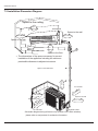
,QVWDOODWLRQ0DQXDO
,QVWDOODWLRQ'LPHQVLRQ'LDJUDP
Space to the ceiling
5.9 in.
Above
Space to the wall
5.9 in. Above
5.9 in. Above
Space to the wall
66
in.
Above
118.1 in.
Above
Air outlet side
Space to the floor
The dimensions of the space necessary for correct
installation of the appliance including the minimum
permissible distances to adjacent structures
Space to the obstruction
19.7 in. Above
●
11.8in. Above
Air inlet side
ve
bo
A
in.
.8
11
Space to the wall
Space to the wall
19.7 in. Above
.
7in
Ab
e
ov
.
78
Air outlet side
valve cover
Schematic diagram being reference only (outdoor unit is with variation),
please refer to real product for authentic information.
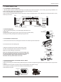
,QVWDOODWLRQ0DQXDO
,QVWDOO,QGRRU8QLW
,QVWDOODWLRQRI0RXQWLQJ3ODWH
0RXQWLQJSODWHVKRXOGEHLQVWDOOHGKRUL]RQWDOO\$VWKHZDWHUWUD\ VRXWOHWIRUWKHLQGRRUXQLWLVWZRZD\W\SHGXULQJLQVWDOODWLRQWKH
LQGRRUXQLWVKRXOGVOLJKWO\VODQWWRZDWHUWUD\ VRXWOHWIRUVPRRWKGUDLQDJHRIFRQGHQVDWH
)L[WKHPRXQWLQJSODWHRQWKHZDOOZLWKVFUHZV
%HVXUHWKDWWKHPRXQWLQJSODWHKDVEHHQ¿[HG¿UPO\HQRXJKWRZLWKVWDQGDERXWLE0HDQZKLOHWKHZHLJKWVKRXOGEHHYHQO\
VKDUHGE\HDFKVFUHZ
Wall
Wall
Mark on the middle of it
Gradienter
Space to
the wall
59.1in.
above
Space to
the wall
59.1in.
above
Right
Left
Φ2.6in.
(Rear piping hole)
(Rear piping hole)
Φ2.6in.
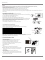
'ULOO3LSLQJ+ROH
6ODQWWKHSLSLQJKROH ĭLQ RQWKHZDOOVOLJKWO\GRZQZDUGWRWKH
RXWGRRUVLGH
,QVHUWWKHSLSLQJKROHVOHHYHLQWRWKHKROHWRSUHYHQWWKHFRQQHFWLRQSLSLQJ
DQGZLULQJIURPEHLQJGDPDJHGZKHQSDVVLQJWKURXJKWKHKROH
Indoor
Wall pipe
Outdoor
Seal pad
Φ2.6
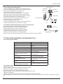
,QVWDOODWLRQRI'UDLQ+RVH
&RQQHFWWKHGUDLQKRVHWRWKHRXWOHWSLSHRIWKHLQGRRUXQLW%LQGWKHMRLQWZLWKUXEEHUEHOW
3XWWKHGUDLQKRVHLQWRLQVXODWLQJWXEH
outlet pipe of
indoor unit
drain hose
outlet pipe of
indoor unit
rubber belt
:UDSWKHLQVXODWLQJWXEHZLWKZLGHUXEEHUEHOWWRSUHYHQW
WKHVKLIWRILQVXODWLQJWXEH6ODQWWKHGUDLQKRVHGRZQZDUG
VOLJKWO\IRUVPRRWKGUDLQDJHRIFRQGHQVDWH
outlet pipe of
indoor unit
drain hose
rubber belt insulating tube
rubber belt
outlet pipe of
indoor unit
1RWH7KHLQVXODWLQJWXEHVKRXOGEHFRQQHFWHGUHOLDEO\ZLWK
WKHVOHHYHRXWVLGHWKHRXWOHWSLSH7KHGUDLQKRVHVKRXOGEH
VODQWHGGRZQZDUGVOLJKWO\ZLWKRXWGLVWRUWLRQEXOJHRU
ÀXFWXDWLRQ'RQRWSXWWKHRXWOHWLQWKHZDWHU
connected
bulge
insulating tube
distortion
Flooded
&RQQHFWLQJ,QGRRUDQG2XWGRRU(OHFWULF:LUHV
2SHQWKHIURQWSDQHO
5HPRYHWKHZLULQJFRYHUDQGZLUHFODPS0DNHWKHSRZHUFRQQHFWLRQFRUGSDVVWKURXJKWKHKROHDWWKHEDFNRILQGRRUXQLW $VVKRZQ
LQ)LJ
&RQQHFWDQG¿[WKHSRZHUFRQQHFWLRQFRUGWRWKHWHUPLQDOERDUG $VVKRZQLQ)LJ
)L[WKHSRZHUFRQQHFWLRQFRUGZLWKZLUHFODPSDQGUHLQVWDOOZLULQJFRYHU
5HLQVWDOOWKHIURQWSDQHO
Wiring Cover
N(1)
2
3
outdoor unit connection
Fig.1
Fig.2
,QVWDOODWLRQ0DQXDO
127(
$OOZLUHVEHWZHHQLQGRRUDQGRXWGRRUXQLWVPXVWEHFRQQHFWHGE\WKHTXDOL¿HGHOHFWULFFRQWUDFWRU
Ɣ(OHFWULFZLUHVPXVWEHFRQQHFWHGFRUUHFWO\,PSURSHUFRQQHFWLRQPD\FDXVHPDOIXQFWLRQ
Ɣ7LJKWHQWKHWHUPLQDOVFUHZVVHFXUHO\
Ɣ$IWHUWLJKWHQLQJWKHVFUHZVSXOOWKHZLUHVOLJKWO\WRFRQ¿UPZKHWKHULW V¿UPRUQRW
Ɣ0DNHVXUHWKDWWKHHOHFWULFFRQQHFWLRQVDUHHDUWKHGSURSHUO\WRSUHYHQWHOHFWULFVKRFN
Ɣ0DNHVXUHWKDWDOOZLULQJFRQQHFWLRQVDUHVHFXUHDQGWKHFRYHUSODWHVDUHUHLQVWDOOHGSURSHUO\3RRULQVWDOODWLRQPD\FDXVH¿UHRU
HOHFWULFVKRFN
,QVWDOODWLRQRI,QGRRU8QLW
Ɣ7KHSLSLQJFDQEHRXWSXWIURPULJKWULJKWUHDUOHIWRUOHIWUHDU
:KHQURXWLQJWKHSLSLQJDQGZLULQJIURPWKHOHIWRUULJKWVLGHRILQGRRUXQLWFXWRIIWKHWDLOLQJV
IURPWKHFKDVVLVZKHQQHFHVVDU\ $VVKRZQLQ)LJ
&XWRIIWDLOLQJZKHQURXWLQJWKHZLULQJRQO\
&XWRIIWDLOLQJDQGWDLOLQJZKHQURXWLQJERWKWKHZLULQJDQGSLSLQJ
7DNHRXWWKHSLSLQJIURPERG\FDVHZUDSWKHSLSLQJSRZHUFRUGVGUDLQKRVHZLWKWKHWDSH
DQGWKHQPDNHWKHPSDVVWKURXJKWKHSLSLQJKROH $VVKRZQLQ)LJ
+DQJWKHPRXQWLQJVORWVRIWKHLQGRRUXQLWRQWKHXSSHUKRRNVRIWKHPRXQWLQJSODWHDQG
FKHFNLILWLV¿UPHQRXJK $VVKRZQLQ)LJ
7KHLQVWDOODWLRQVLWHVKRXOGEHLQRUPRUHDERYHWKHÀRRU
External connection
Gas side piping electric wire
Liquid side
piping
Tailing 3
Tailing 2
Tailing1
Fig.3
Liquid side
Gas side piping
piping
insulation
Finally wrap it
insulation
with tape
Water drainage pipe
Fig.4
Left
Right
Right rear
Left rear
Fixing hook
Mounting
board
Mounting
board
Fig.5
,QVWDOODWLRQRI&RQQHFWLRQ3LSH
$OLJQWKHFHQWHURIWKHSLSHÀDUHZLWKWKHUHODWHGYDOYH
6FUHZLQWKHÀDUHQXWE\KDQGDQGWKHQWLJKWHQWKHQXWZLWKVSDQQHUDQGWRUTXH
ZUHQFKE\UHIHUULQJWRWKHIROORZLQJ
7XEHGLDPHWHU
7LJKWHQLQJWRUTXHDSSUR[LPDWH 1ÂP
Ɏ ´
̚1ÂP NJIFP
Ɏ ´
̚1ÂP NJIFP
Ɏ ´
̚1ÂP NJIFP
Ɏ ´
̚1ÂP NJIFP
Indoor unit piping
Spanner
127(&RQQHFWWKHFRQQHFWLRQSLSHWRLQGRRUXQLWDW¿UVWDQGWKHQWRRXWGRRUXQLW+DQGOHSLSLQJ
EHQGLQJZLWKFDUH'RQRWGDPDJHWKHFRQQHFWLRQSLSH(QVXUHWKDWWKHMRLQWQXW
LVWLJKWHQHG¿UPO\RWKHUZLVHLWPD\FDXVHOHDNDJH
,QVWDOO2XWGRRU8QLW
Taper nut Piping
Torque
wrench
Handle
(OHFWULF:LULQJ
5HPRYHWKHKDQGOHRQWKHULJKWVLGHSODWHRIRXWGRRUXQLW
,QVHUWWKHDLUEXWWWHUPLQDORISRZHUFRQQHFWLRQFRUG
DQGSRZHUFRUGWLJKWO\DQGUHOLDEO\E\UHIHUULQJWRWKH
ZLULQJGLDJUDPRIRXWGRRUXQLW)LQDOO\¿[WKHSRZHUFRQQHFWLRQ
FRUGDQGSRZHUFRUGZHOOZLWKZLUHFODPS
5HLQVWDOOWKHKDQGOH
127(
:URQJZLULQJPD\FDXVHVSDUHSDUWVPDOIXQFWLRQ
$IWHUWKHFDEOH¿[HGPDNHVXUHWKHUHVKRXOGEHDIUHHVSDFH
EHWZHHQWKHFRQQHFWLRQDQGFRQQHFWLRQDQG¿[LQJSODFHRQ
WKHOHDGZLUH
7KHFRQQHFWLQJZLUHDQGFRQQHFWLRQSLSHFDQQQRW
WRXFKHDFKRWKHU
7RSFRYHURIRXWGRRUXQLWDQGHOHFWULFER[DVVHPEO\VKRXOG
EH¿[HGE\WKHVFUHZ2WKHUZLVHLWFDQFDXVHD¿UHRUVKRUW
FLUFXLWFDXVHGE\ZDWHURUGXVW
Indoor unit connection
wire pip
e
Fixed nut
Finish
,QVWDOODWLRQ0DQXDO
$LU3XUJLQJDQG/HDNDJH7HVW
Manifold Valve
&RQQHFWFKDUJLQJKRVHRIPDQLIROGYDOYHWRFKDUJHHQGRIORZ
SUHVVXUHYDOYH ERWKKLJKORZSUHVVXUHYDOYHVPXVWEHWLJKWO\VKXW &RQQHFWMRLQWRIFKDUJLQJKRVHWRYDFXXPSXPS
)XOO\RSHQWKHKDQGOHRI/RPDQLIROGYDOYH
2SHQWKHYDFXXPSXPSIRUYDFXXPL]DWLRQ$WWKHEHJLQQLQJ
VOLJKWO\ORRVHQMRLQWQXWRIORZSUHVVXUHYDOYHWRFKHFNLIWKHUH
LVDLUFRPLQJLQVLGH ,IQRLVHRIYDFXXPSXPSKDVEHHQFKDQJHG
WKHUHDGLQJRIPXOWLPHWHULV 7KHQWLJKWHQWKHQXW
.HHSYDFXXPLQJIRUPRUHWKDQPLQVDQGPDNHVXUHWKH
UHDGLQJRIPXOWLPHWHULV36, LQ+J )XOO\RSHQKLJKORZSUHVVXUHYDOYHV
5HPRYHFKDUJLQJKRVHIURPFKDUJLQJHQGRIORZSUHVVXUHYDOYH
7LJKWHQOLGRIORZSUHVVXUHYDOYH $VVKRZQLQ)LJ
Multimeter
-29.9in.Hg
Manometer
Hi handle
Lo Handle
Charging hose
Low pressure valve
Vacuum pump
Fig.6
2XWGRRU&RQGHQVDWH'UDLQDJH RQO\IRUKHDWSXPSXQLW
'XULQJKHDWLQJRSHUDWLRQWKHFRQGHQVDWHDQGGHIURVWLQJ
ZDWHUVKRXOGEHGUDLQHGRXWUHOLDEO\WKURXJKWKHGUDLQKRVH
,QVWDOOWKHRXWGRRUGUDLQFRQQHFWRULQDĭLQKROHRQ
WKHEDVHSODWHDQGDWWDFKWKHGUDLQKRVHWRWKHFRQQHFWRU
VRWKDWWKHZDVWHZDWHUIRUPHGLQWKHRXWGRRUXQLWFDQEH
GUDLQHGRXW7KHKROHGLDPHWHULQPXVWEHSOXJJHG
:KHWKHUWRSOXJRWKHUKROHVZLOOEHGHWHUPLQHGE\WKHGHDOHUVDFFRUGLQJWRDFWXDOFRQGLWLRQV
Drain-water hole
Bottom frame
Drain plug
Drain connecter
Hose (available commercially,
inner dia. 16mm)
&KHFNDIWHU,QVWDOODWLRQDQG2SHUDWLRQ7HVW
&KHFNDIWHU,QVWDOODWLRQ
,WHPVWREHFKHFNHG
3RVVLEOHPDOIXQFWLRQ
+DVLWEHHQ¿[HG¿UPO\"
7KHXQLWPD\GURSVKDNHRUHPLWQRLVH
+DYH\RXGRQHWKHUHIULJHUDQWOHDNDJH ,WPD\FDXVHLQVXI¿FLHQWFRROLQJ KHDWLQJ
WHVW"
FDSDFLW\
,VKHDWLQVXODWLRQVXI¿FLHQW"
,WPD\FDXVHFRQGHQVDWLRQDQGGULSSLQJ
,VZDWHUGUDLQDJHVDWLVIDFWRU\"
,WPD\FDXVHFRQGHQVDWLRQDQGGULSSLQJ
,VWKHYROWDJHLQDFFRUGDQFHZLWKWKH
,WPD\FDXVHHOHFWULFPDOIXQFWLRQRU
UDWHGYROWDJHPDUNHGRQWKHQDPHSODWH" GDPDJHWKHSURGXFW
,VWKHHOHFWULFZLULQJDQGSLSLQJ
,WPD\FDXVHHOHFWULFPDOIXQFWLRQRU
FRQQHFWLRQLQVWDOOHGFRUUHFWO\DQG
GDPDJHWKHSDUW
VHFXUHO\"
+DVWKHXQLWEHHQFRQQHFWHGWRDVHFXUH
,WPD\FDXVHHOHFWULFDOOHDNDJH
HDUWKFRQQHFWLRQ"
,WPD\FDXVHHOHFWULFPDOIXQFWLRQRU
,VWKHSRZHUFRUGVSHFL¿HG"
GDPDJHWKHSDUW
$UHWKHLQOHWDQGRXWOHWRSHQLQJV
,WPD\FDXVHLQVXI¿FLHQWFRROLQJ KHDWLQJ EORFNHG"
FDSDFLW\
,VWKHOHQJWKRIFRQQHFWLRQSLSHVDQG
7KHUHIULJHUDQWFDSDFLW\LVQRWDFFXUDWH
UHIULJHUDQWFDSDFLW\EHHQUHFRUGHG"
2SHUDWLRQ7HVW
%HIRUH2SHUDWLRQ7HVW
'RQRWVZLWFKRQSRZHUEHIRUHLQVWDOODWLRQLV¿QLVKHGFRPSOHWHO\
(OHFWULFZLULQJPXVWEHFRQQHFWHGFRUUHFWO\DQGVHFXUHO\
&XWRIIYDOYHVRIWKHFRQQHFWLRQSLSHVVKRXOGEHRSHQHG
$OOWKHLPSXULWLHVVXFKDVVFUDSVDQGWKUXPVPXVWEHFOHDUHGIURPWKHXQLW
2SHUDWLRQ7HVW0HWKRG
6ZLWFKRQSRZHUDQGSUHVV212))EXWWRQRQWKHUHPRWHFRQWUROOHUWRVWDUWRSHUDWLRQ
3UHVV02'(EXWWRQWRVHOHFWWKH&22/+($7 1RWDYDLODEOHIRUFRROLQJRQO\XQLW )$1WRFKHFNZKHWKHUWKHRSHUDWLRQLVQRUPDORU
QRW
,QVWDOODWLRQ0DQXDO
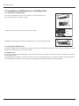
,QVWDOODWLRQDQG0DLQWHQDQFHRI+HDOWK\)LOWHU
,QVWDOODWLRQRI+HDOWK\)LOWHU
/LIWXSWKHIURQWSDQHOIURPLWVWZRHQGVDVVKRZQE\WKHDUURZGLUHFWLRQDQG
WKHQUHPRYHWKHDLU¿OWHU $VVKRZQLQ¿JD
Fig. a
Fig. b
$WWDFKWKHKHDOWK\¿OWHURQWRWKHDLU¿OWHU DVVKRZQLQ¿JE
Air filter
Healthy filter
,QVWDOOWKHDLU¿OWHUSURSHUO\DORQJWKHDUURZGLUHFWLRQLQ)LJFDQGWKHQFORVHWKHSDQHO
Fig.
c
&OHDQLQJDQG0DLQWHQDQFH
5HPRYHWKHKHDOWK\¿OWHUDQGUHLQVWDOOLWDIWHUFOHDQLQJDFFRUGLQJWRWKHLQVWDOODWLRQLQVWUXFWLRQ'RQ WXVHEUXVKRUKDUGWKLQJVWRFOHDQ
WKH¿OWHU$IWHUFOHDQLQJEHVXUHWRGU\LWLQWKHVKDGH
6HUYLFH/LIH
7KHJHQHUDOVHULYHOLIHIRUWKHKHDOWK\¿OWHULVDERXWRQH\HDUXQGHUQRUPDOFRQGLWLRQ$VIRUVLOYHULRQ¿OWHULWLVLQYDOLGZKHQLWVVXUIDFH
EHFRPHVEODFN JUHHQ Ɣ7KLVVXSSOHPHQWDU\LQVWUXFWLRQLVSURYLGHGIRUUHIHUHQFHWRWKHXQLWZLWKKHDOWK\¿OWHU,IWKHJUDSKLFVSURYLGHGKHUHLQLVGLIIHUHQWIURP
WKHDFWXDOSURGXFWSOHDVHUHIHUWRWKHDWXDOSURGXFW7KHTXDQWLW\RIKHDOWK\¿OWHUVLVEDVHGRQWKHDFWXDOGHOLYHU\
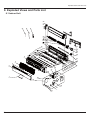
([SORGHG9LHZVDQG3DUWV/LVW
([SORGHG9LHZVDQG3DUWV/LVW
,QGRRU8QLW
22
21
46
45
44
20
19
18
17
16
6
7
8
9
10
12
11
13
14
15
23
24
25
26
5
27
28
4
3
29
2
36
37
35
38
1
39
40
43
42
41
34
33
32
31
30
([SORGHG9LHZVDQG3DUWV/LVW
12
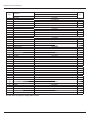
'HVFULSWLRQ
3URGXFW&RGH
5HFHLYHU:LQGRZ
)URQW3DQHO
6WDQGEDU
A16EM4H4R36
4W\
&%1
6
)LOWHU6XE$VV\
)URQW&DVH6XE$VV\
8SSHU*XLGH/RXYHU
/RZHUJXLGHORXYHU
$[LOH%XVK
$LU/RXYHU
$LU/RXYHU
&RQQHFWLQJ5RG
/RXYHU&ODPS
:DWHU7UD\
6FUHZ&RYHU
5XEEHU3OXJ :DWHU7UD\
5HDU&DVH6XE$VV\
&URVV)ORZ)DQ
%HDULQJ+ROGHUVXEDVV\
&URVV)ORZ)DQ
2*DVNHWVXEDVV\RI%HDULQJ
/HIW(YDSRUDWRU6XSSRUW
(YDSRUDWRU$VV\
:DOO0RXQWLQJ)UDPH
5LJKW6XSSRUWRI(YDSRUDWRU
)DQ0RWRU
C
3LSH&ODPS
'UDLQDJHKRVH
0RWRU)L[HG&OLS
6WHS0RWRU
)L[HG&OLS HYDSRUDWRU
&RYHU3ODWH
3UHVVSODWH FUDQN
&UDQNJXLGH
8SSHU&UDQN
/RZHUFUDQN
(OHFWULF%R[$VV\
(OHFWULF%R[
7UDQVIRUPHU
7HUPLQDO%RDUG
0DLQ%RDUG
'LVSOD\%RDUG
(OHFWULF%R[&RYHU
(OHFWULF%R[&RYHU
6
5HPRWH&RQWUROOHU
7XEH6HQVRU
$PELHQW7HPSHUDWXUH6HQVRU
7KHGDWDDERYHDUHVXEMHFWWRFKDQJHZLWKRXWQRWLFH
3DUW&RGH
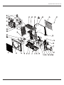
([SORGHG9LHZVDQG3DUWV/LVW
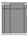
([SORGHG9LHZVDQG3DUWV/LVW
12
'HVFULSWLRQ
3URGXFW&RGH
)URQW*ULOO
&DELQHW
)URQW6LGH3ODWH
$[LDO)ORZ)DQ
'UDLQDJH3OXJ
&KDVVLV6XEDVV\
'UDLQDJH&RQQHFWHU
&RPSUHVVRU*DVNHW
&RPSUHVVRUDQG¿WWLQJV
HOHFWULFDOKHDWHU
0DJQHW&RLO
ZD\9DOYH$VV\
5LJKW6LGH3ODWH
9DOYH6XSSRUW6XE$VV\
&XWRII9DOYH
9DOYHFRYHU
5HWDLQLQJSODWH
+DQGOHDVV\
:LULQJFODPS
&DSLOODU\6XE$VV\
7HPSHUDWXUH6HQVRU
5HDU*ULOO
&RQGHQVHU$VV\
&ODSERDUG
&RQGHQVHUVXSSRUWSODWH
0RWRU6XSSRUW6XE$VV\
7RS&RYHU6XE$VV\
(OHFWULF%R[&RYHU
5HDFWRU
(OHFWULF%R[6XE$VV\
3DVVZLUHULQJVXEDVV\
OHIWKDQGOH
/HIW6LGH3ODWH
)DQ0RWRU
(OHFWULF%R[&RYHU
0DLQ%RDUG
(OHFWULF%R[
5DGLDWRU
7HUPLQDO%RDUG
(OHFWULF%R[$VV\
&DSLOODU\VXEDVV\ RLOUHWXUQLQJ
(OHFWULFDO+HDWHU &KDVVLV
3DUW&RGH
A16CI4H4R36
&%:
3
3
3
3
3
3
3
4W\
7KHGDWDDERYHDUHVXEMHFWWRFKDQJHZLWKRXWQRWLFH
7URXEOHVKRRWLQJ
7URXEOHVKRRWLQJ
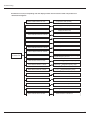
0DOIXQFWLRQ$QDO\VLV
Note: When replacing the controller, make sure insert the wire jumper into the new controller, otherwise the
unit will display C5
The breaker trips at once when it
is set to "ON".
Trip of breaker
or blow of fuse
The circuit or the part of the air conditioner has
malfunction. They heat and break the insulation
and lead to short circuit or creepage. Measure
the insulation resistance or eliminate the malfunction one by one. If the breaker itself has
malfunction, then replace the breaker.
The breaker trips in few
minutes when it is set
to "ON"
Check power supply circuit.
Air conditioner can not start up
No power
The air conditioner does not react
after it is powered ( after the plug
is inserted,
the buzzer does
not sound and
the remote startup has
no response)
The remote controller does not
receive signals
(after it is
powered, the
buzzer will
sound, unless it
has malfunction)
Power plug is not well plugged in
and poor con-nection
Check if the plug is properly
plugged in and make the loose
contact firm.
Fuse of controller burnt out
Change controller fuse
The transformer connection is loose or
has bad contact or the transformer
has malfunction
Fasten the wiring; measure the
output voltage of the transformer, if
it is incorrect, change the
transformer
Controller is broken
Check remote controller
Remote controller is short of power
Change batteries
Remote controller malfunction
First, press the manual switch button
AUTO, if there is no response,check
based on the above methods. If it runs
normally after pressing the button,
check again whether the installation
position and the connection wire
of the reception head is correct. If it is
correct,then replace the receiver or the
remote controller.
Receiver loose or poor connection
Receiver is broken
Power voltage is too low
Measure insulation resistance
to ground to see if there is any
leakage.
Check the voltage. If it is lower than 10%of the
rated voltage, check the cause, improve the power
supply condition and add the stabilized voltage
power supply.
7URXEOHVKRRWLQJ
Improper set of temperature
Adjust set temperature
If cooling load is proper
Check the forecasted load of cooling
The refrigerant has leakage
or is insufficient
Check and fill the leakage, then
vacuumize it and supplement the
refrigerant as required
Leakage between the high pres-
Malfunction of
refrigerant flow
sure and the low pressure inside the compressor
Malfunction of four-way valve
Poor COOL operation
Local block of capillary
Blockage of cooling system
Heat insulation for the connection
pipes of the indoor unit and the outdoor unit is bad.
Replace the compressor
Replace the four-way valve
Replace the capillary
Judge whether the system is blocked
by observing the condensation of
evaporator and the pressure value of
the high pressure manometer and
take measuresto deal with the
system.
Make sure that heat insulation for the thick and thin pipes
is good. Heat insulation must also be provided for the
joint andthe exposed part of the copper pipe .
Block of outdoor heat exchanger
Clean the dust accumulated on the
surface of the heat exchanger.
Air filter were blocked
Clean the filter
Fan speed was set too slow
Air circulation
is insufficient
Fan rotation speed becomes
low
The installation position of
the outdoor unit is not
appropriate.
The outdoor temperature is too high.
The air tightness is not enough. People
come in and out too frequently. There
are heating devices indoors.
To set the fan speed to high or
middle speed
Capacitor
damage
Replace the capacitor
Motor
damage
Replace the motor
Good ventilation must be provided for the
installation position of the outdoor unit.
Properly install the rainproof plate or the sunproof
plate. If the maximum cool air still can not meet the
requirement, it is suggested to replace the air
conditioner.
Keep certain air tightness indoors, try not to use
electricalappliance with large quantity of heat
7URXEOHVKRRWLQJ
The indoor fan motor is burned or breaks
or has the heat protector malfunction.
The fan does not
run when it is set
to supply air.
In the cooling
mode, the compressor runs, but
the outdoor fan
does not run.
When cooling
outdoor fanruns,
compressor
doesn't run.
The built-in heat protector of the motor
breaks frequently because the motor is
abnormal.
Replace the fan motor
Wrong connection
Make the correction connection based on the
circuit drawing.
The fan capacitor has open circuit or is
damaged.
Replace the fan capacitor of the same type and
same specification.
The outdoor fan motor is damaged.
Replace the fan motor
Wrong connection
Make the correct connection based on the
circuit drawing.
The outdoor fan capacitor is damaged.
Replace the fan capacitor
M al f uncti on of compressor
Repl ace the compressor
Breakage of running capacitor of
compressor
Replace the capacitor
The voltage is too low or too high.
Manostat is recommended.
Wrong wire connection
Connect the circuit diagram correctly
The protector itself has malfunction.
The compressor is
too hot and leads
to the action of
the protector.
Replace the fan motor or the defective part.
Use the multimeter to check whether the contact of
the compressor is on when it is not overheated. If it
is not on, then replace the protector
The refrigerant is not enough or is too
much.
Adjust the volume of the refrigerant
The capillary is blocked and the temperature rises.
Replace the capillary
The compressor does not run smoothly or
is stuck. The air discharge valve is
damaged
Replace the compressor
The protector itself has malfunction.
Replace the protector
The torque of the swing motor is not
enough
The swing fan does
not run.
wrong connection
The controller is damaged(IC2003 is
damaged, the swing relay can not close,
etc )
First, check whether the connection is wrong.
If no, replace the parts
7URXEOHVKRRWLQJ
Controller malfunction
( I C 2 0 0 3 b r o k e n , creepage of
parallel capacitor of relay loop,
relay is broken etc.)
In cool mode,
the outdoor unit
and compressor
will not run.
Wire loose or wrong connection
Change controller
Correctly wire according to the drawing
Improper setting of temperature
Adjust setting temp.
Drainage pipe blocked or broken
Change drainage pipe
Wrap of refrigerant pipe joint is not close
Re-wrap and make it tight.
Water leakage
enough.
Fan of indoor unit contacts other parts
Abnormal sound
and shake
Adjust fan location.
Foreign object in indoor unit
Take out the foreign object.
Compressor shakes too much.
Adjust support washer of compressor, and
tighten loosen screws.
Touch of pipeline of outdoor unit
Separate the touching pipeline.
Touch of inner plates
1. Tighten connect screw.
2. Stick absorbing clay between plates.
Louver of outdoor unit touched outer
case.
Adjust location of louver.
Abnormal sound inside compressor
Change compressor
7URXEOHVKRRWLQJ
)ODVKLQJ/('RI,QGRRU2XWGRRU8QLWDQG3ULPDU\-XGJHPHQW
No feedback of outdoor fan motor
High-preesure Protection
E1
7URXEOHVKRRWLQJ
If malfunction occurs,corresponding code will display and the unit will resume normal until protection or
malfunction disappears.
Yellow indicator blinks for once
Yellow indicator blinks for twice
Yellow indicator blinks for 3 times
Compressor stars (normal)
Defrosting (normal display of indoor unit)
Anti-freezing protection (normal
display of indoor unit)
Yellow indicator blinks for 4 times
IPM protection
Yellow indicator blinks for 5 times
Overcurrent protection
Yellow indicator blinks for 6 times
Overload protection
Yellow indicator blinks for 7 times
Exhaust protection
Yellow indicator blinks for 8 times
Overlod protection of compresoor
Indicator display
of outdoor unit
Red indicator blinks for once
Red indicator blinks for twice
Cooling (dehumidify) or heating current
dropped frequency current.
Exhaust temp.
dropped frequency temp.
Red indicator blinksfor 3 times
Tube temp.
Red indicator blinks for 4 times
T tube-in
Red indicator blinks for 5 times
Outdoor condenser temp. sensor mal.
Red indicator for 6 times
dropped frequency temp.
dropped frequency temp.
Outdoor ambient temp. sensor mal.
Red indicator blinks for 7 times
Outdoor exhaust temp. sensor mal.
Red indicator blinks for 8 times
Starting at temp. does not reach
Green indicator does not blink
Communication is abnormal
7URXEOHVKRRWLQJ
$QDO\VLVRUSURFHVVLQJRIVRPHRIWKHPDOIXQFWLRQGLVSOD\
&RPSUHVVRUGLVFKDUJHSURWHFWLRQ
3RVVLEOHUHDVRQVVKRUWDJHRIUHIULJHUDQWEORFNDJHRIDLU¿OWHUSRRUYHQWLODWLRQRUDLUÀRZVKRUWSDVVIRUFRQGHQVHUWKHV\VWHPKDV
QRQFRQGHQVLQJJDV VXFKDVDLUZDWHUHWF EORFNDJHRIFDSLOODU\DVV\ LQFOXGLQJ¿OWHU OHDNDJHLQVLGHIRXUZD\YDOYHFDXVHVLQFRUUHFW
RSHUDWLRQPDOIXQFWLRQRIFRPSUHVVRUPDOIXQFWLRQRISURWHFWLRQUHOD\PDOIXQFWLRQRIGLVFKDUJHVHQVRURXWGRRUWHPSHUDWXUHWRR
KLJK
3URFHVVLQJPHWKRGUHIHUWRWKHPDOIXQFWLRQDQDO\VLVLQWKHDERYHVHFWLRQ
/RZYROWDJHRYHUFXUUHQWSURWHFWLRQ
3RVVLEOHUHDVRQ6XGGHQGURSRIVXSSO\YROWDJH
&RPPXQLFDWLRQPDOIXQFWLRQ
3URFHVVLQJPHWKRG&KHFNLIFRPPXQLFDWLRQVLJQDOFDEOHLVFRQQHFWHGUHOLDEO\
6HQVRURSHQRUVKRUWFLUFXLW
3URFHVVLQJPHWKRG&KHFNZKHWKHUVHQVRULVQRUPDOFRQQHFWHGZLWKWKHFRUUHVSRQGLQJSRVLWLRQRQWKHFRQWUROOHUDQGLIGDPDJHRI
OHDGZLUHLVIRXQG
&RPSUHVVRURYHUORDGSURWHFWLRQ
3RVVLEOH UHDVRQV LQVXIILFLHQW RU WRR PXFK UHIULJUDQW EORFNDJH RI FDSLOODU\ DQ GLQFUHDVH RI VXFWLRQ WHPS LPSURSHU UXQQLQJ RI
FRPSUHVVRUEXUQLQJLQRUVWXFNRIEHDULQJGDPDJHRIGLVFKDUJHYDOYHPDOIXQFWLRQRISURWHFWRU
3URFHVVLQJPHWKRGDGMXVWUHIULJHUDQWDPRXQWUHSODFHWKHFDSLOODU\UHSODFHWKHFRPSUHVVRUXVHXQLYHUVDOPHWHUWRFKHFNLIWKH
FRQWDFWRURIFRPSUHVVRULV¿QHZKHQLWLVQRWRYHUKHDWHGLIQRWUHSODFHWKHSURWHFWRU
6\VWHPPDOIXQFWLRQ
2YHUORDG SURWHFWLRQ:KHQ WXEH WHPSHUDWXUH &KHFN WKH WHPSHUDWXUH RI RXWGRRU KHDW H[FKDQJHU ZKHQ FRROLQJ DQG FKHFN WKH
WHPSHUDWXUHRILQGRRUKHDWH[FKDQJHUZKHQKHDWLQJ LVWRRKLJKSURWHFWLRQZLOOEHDFWLYDWHG
3RVVLEOHUHDVRQV2XWGRRUWHPSHUDWXUHLVWRRKLJKZKHQFRROLQJLQVXI¿FLHQWRXWGRRUDLUFLUFXODWLRQUHIULJHUDQWÀRZPDOIXQFWLRQ
3OHDVHUHIHUWRWKHPDOIXQFWLRQDQDO\VLVLQWKHSUHYLRXVVHFWLRQIRUKDQGOLQJPHWKRG
,30PRGXOHSURWHFWLRQ
3URFHVVLQJPHWKRG2QFHWKHPRGXOHPDOIXQFWLRQKDSSHQVLILWSHUVLVWVIRUDORQJWLPHDQGFDQQRWEHVHOIFDQFHOHGFXWRIIWKH
SRZHUDQGWXUQRIIWKHXQLWDQGWKHQUHHQHUJL]HWKHXQLWDJDLQDIWHUDERXWPLQ$IWHUUHSHDWLQJWKHSURFHGXUHIRUVHYHUWLPHVLI
WKHPDOIXQFWLRQVWLOOH[LVWVUHSODFHWKHPRGXOH
7URXEOHVKRRWLQJ
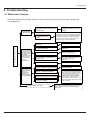
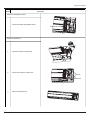
+RZWR&KHFN6LPSO\WKH0DLQ3DUW
(1) Capacitor charge fault (Fault with outdoor unit) (AP1 below refers to the outdoor control panel)
Main Check Points:
Use AC voltmeter to check if the voltage between terminal L and N on the wiring board is within 210VAC~240VAC.
If the reactor (L) is correctly connected? If the connection is loose or fallen? If the reactor (L) is damaged?
Fault diagnosis process:
Turn on the unit
and wait 1 minute
Use DC voltmeter
to measure the
voltage on the two
ends of electrolytic
capacitor
Voltage higher than 200V?
Y
Fault with the voltage
testing circuit on
control panel AP1
Replace the control
panel AP1
N
Measure the AC voltage between
terminalL and N on wiring board
XT(power supply)
Voltage within
210VAC~250VAC?
N
Shut down the power
and repair the power
supply to restore the
range
210VAC~250VAC
power on and
restart the unit
If the fault is
eliminated?
Y
Y
Shut down the power and wait 20 minutes;or
use DC voltmeter to measure the voltage
on the two ends of capacitor , until
the voltage is lower than 20V
N
Check the
connection of reactor
(L in the Electrical
Wiring Diagram)
If the wiring of
reactor Lis normal?
N
Connect the reactor
Laccording to Electrical Wiring Diagram correctly
Re-energize and
turn on the unit
If the fault is
eliminated?
Y
Y
Replace the control
panel AP1
N
End
7URXEOHVKRRWLQJ
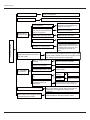
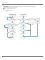
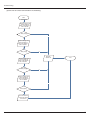
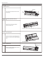
(2) IPM Protection, Out-of-step Fault, Compressor Phase Overcurrent (AP1 below refers to the outdoor control panel)
Main check points:
If the connection between control panel AP1 and compressor COMP is secure? If loose? If the connection is in correct order?
If the voltage input of the machine is within normal range? (Use AC voltmeter to measure the voltage between terminal L and
N on the wiring board XT)
If the compressor coil resistance is normal? If the insulation of compressor coil against the copper tube is in good condition?
If the working load of the machine are too high? If the radiation is good?
If the charge volume of refrigerant is correct?
Fault diagnosis process:
Energize and
switch on
IPM protection
occurs after the
machine has run for
a period of time?
Y
Use AC voltmeter
to measure the
voltage between
terminal L and N
on the wiring
board XT)
If the voltage
between terminal L
and N on wiring
board XT is within
210VAC~250VAC?
N
Check the supply
voltage and
restore it to
210VAC~250VAC
Y
Restart the unit. Before
protection occurs,
use DC voltmeter to
measure the voltage
between the two
ends of electrolytic
capacitor on control
panel AP1
Voltage between
the two ends of celectrolytic
capacitor is
higher than
250V
Y
Please confirm:
1. If the indoor and
outdoor heat
exchangers are
dirty? If they are
obstructed by other
objects which affect
the heat exchange
of indoor and
outdoor unit.
2. If the indoor and
outdoor fans are
working normally?
3. If the environment
temperature is too
high, resulting in
that the system
pressure is too high
and exceeds the
permissible range?
4. If the charge
volume of
refrigerant is too
much, resulting in
that the system
pressure is too
high?
5. Other conditions
resulting in that the
system pressure
becomes too high.
The connection
of capacitor C2
is loose.
N
If capacitor
C2 is failed?
Replace the capacitor
C2. Then, energize
and start the unit.
Y
Replace the
control panel AP1
N
If there is any
abnormality
described above?
Y
Y
Replace the
control panel AP1
Connect the control panel
AP1 and compressor
COMP correctly according
to the Electrical Wiring
Diagram. Then, energize
and start the unit.
If the
resistance is
normal?
N
Resistance higher
than 500MΩ?
Y
Replace the
control panel
AP1
END
N
If the unit can
work normallv?
If the unit can
work normally?
Y
Y
N
Take corrective actions
according to Technical
Service Manual, and
then energize and start
the unit.
If the unit can
work
normally?
Replace the
compressor
COMP
N
Use ohmmeter to
measure the resistance
between the two
terminals of compressor
COMP and copper tube.
Reconnect the
capacitor C2 according
to Electrical Wiring
Diagram. Then,
Restart the
unit.
Y
Stop the unit and
disconnect the power
supply. Wait 20 minutes,
or use DC voltmeter to
measure the voltage
between the two ends of
capacitor C2, until the
voltage is lower than 20V
Remove the wires
on the two ends of
capacitor C2. Then,
use capacitance
meter to measure
the capacitor C2.
Verify as per the
Parameters Sheet.
N
Use ohmmeter to
measure the resistance
between the three
terminals on compressor
COMP, and compare the
measurements with the
compressor resistance on
Service Manual.
Y
N
Stop the unit and
disconnect the power
supply. Then, check
the connection of
capacitor C2
according to Electrical
Wiring Diagram.
Refer to the
Electrical Wiring
Diagram and check
if the connection
between AP1 and
COMP is loose and if
the connection order
is correct.
If the connection
between AP1 and
COMP is unsecure
or the connection
order is wrong?
If the unit can
work
normally?
N
If the unit can
work normally?
N
Y
Y
7URXEOHVKRRWLQJ
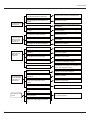
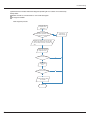
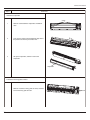
(3)High temperature and overload protection diagnosis (AP1 hereinafter refers to the control board of the outdoor unit)
Mainly detect:
Is outdoor ambient temperature in normal range?
Are the outdoor and indoor fans operating normally?
Is the heat dissipation environment inside and outside the unit is good?
Fault diagnosis process:
Overheat and high
temperature protection
Is outdoor ambient temperature higher than 53?
Y
Normal protection, please operate
it after the outdoor ambient temperature is normalized.
N
20 minutes after the complete
unit is powered off.
Is heat dissipation of the indoor unit
and outdoor unit abnormal?
Y
Improve the heat
dissipation environment of the unit
N
Does the outdoor fan work normally?
N
1. Check if the fan terminal OFAN
is connected correctly
2. Resistance between any two
terminals is measure by an ohm
gauge and should be less than 1K
Ohm.
Y
Replace the fan
capacitor C1
Replace the
control panel AP1
Replace the
outdoor fan
End
7URXEOHVKRRWLQJ
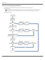
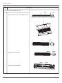
(4) Start-up failure (following AP1 for outdoor unit control board)
Mainly detect:
Whether the compressor wiring is connected correct?
Is compressor broken?
Is time for compressor stopping enough?
Fault diagnosis process:
Power on the unit
Is stop time of the compressor
longer than 3 minutes?
Restart it up after
3 minutes
N
Y
Does startup fail?
Y
Are the wires for the compressor connected
correctly? Is connection sequence right?
N
Y
Replace the control panel AP1
N
If the fault is eliminated?
N
Replace the
compressor
Y
End
Connect the wires as
per the connection
diagram
7URXEOHVKRRWLQJ
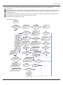
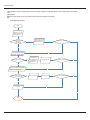
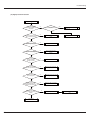
(5) Out of step diagnosis for the compressor (AP1 hereinafter refers to the control board of the outdoor unit)
Mainly detect:
Whether the system pressure is too high?
Whether the input voltage is too low?
Fault diagnosis process:
Out of step occurs once the
unit is powered on.
Out of step occurs in
operation
Is stop time of the
compressor longer than
3 minutes?
Is the outdoor fan working
normally?
Is the outdoor unit blocked
by foreign objects?
Are the wires for the compressor connected
correctly? Is connection sequence right?
Is the connection made in clockwise
direction?
Check if the fan terminal
OFAN is connected correctly
Replace the fan
capacitor C1
Replace the
outdoor fan
Remove foreign objects
Replace the
control panel AP1
Connect the
wires correctly
Replace the control
panel AP1
If the fault is eliminated?
If the fault is eliminated?
Replace the
compressor
Replace the
compressor
End
End
7URXEOHVKRRWLQJ
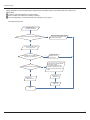
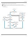
(6)Overload and air exhaust malfunction diagnosis (following AP1 for outdoor unit control board)
Mainly detect:
Wether the PMV is connected well or not? Is PMV damaged?
Is refrigerant leaked?
Fault diagnosis process:
20 minutes after the
complete unit is
powered off
Is the terminal FA for the
electronic expansion valve
connected correctly?
Resistances between the first four pins
close to the terminal hole and the fifth
pin are almost the same, less than 100
ohm.
Replace the electronic
expansion valve
If the fault is eliminated?
Replace the
control panel
AP1
If the fault is eliminated?
Coolant leakage, refilling
the coolant
End
Connect the
wires correctly
7URXEOHVKRRWLQJ
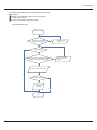
(7)Power factor correct or (PFC) fault (a fault of outdoor unit) (AP1 hereinafter refers to the control board of the outdoor
unit)
Mainly detect:
Check if the reactor (L) of the outdoor unit and the PFC capacitor are broken
Fault diagnosis process:
Start
Check wiring of the
reactor (L) of the
outdoor unit and the
PFC capacitor
Whether there is any
damage or
short-circuit?
Y
Replace it as per the
wiring diagram and
reconnect the wires
If the fault is eliminated?
N
Remove the PFC capacitor
and measure resistance
between the two terminals.
Is the resistance around zero?
N
Y
The capacitor is
short circuited and
the capacitor
should be replaced
Restart the unit
If the fault is eliminated?
Y
N
Disconnect the terminals for the
reactor and measure the resistance
between the two terminals of the
reactor by an ohm gauge
Whether there is any damage
or short-circuit?
N
Y
Replace the reactor
Restart the unit
If the fault is eliminated?
Y
N
Replace the control
panel AP1
N
Y
End
7URXEOHVKRRWLQJ
(8) Communication malfunction: (following AP1 for outdoor unit control board)
Mainly detect:
Is there any damage for the indoor unit mainboard communication circuit? Is communication circuit damaged?
Detect the indoor and outdoor units connection wire and indoor and outdoor units inside wiring is connect well or not, if is
there any damage?
Fault diagnosis process:
Start
Y
Did the equipment operate
normally before the failure
occurs?
N
Check the wiring of the indoor and
outdoor units with reference to the
wiring diagram
Check wiring inside of
the indoor and outdoor
units
Y
Is the connection right?
N
N
The AP1 voltage
detection circuit
is at fault
Y
Correctly connect the
corresponding wires for
the indoor and outdoor
units with reference to
the wiring diagram
Are wires broken?
N
If the fault is eliminated?
N
Check the communication
circuit of the outdoor unit
If the fault is eliminated?
The communication
circuit is abnormal
Y
N
Replace the main board
AP1 of the outdoor unit
If the fault is eliminated?
N
Replace the main board
of the indoor unit
Y
Y
End
Y
7URXEOHVKRRWLQJ
(9) Flow chart for outdoor communitcation circuit detecting:
Start
Measure voltage at the
Test 10 position as
shown in the diagram
with a voltmeter
Value jumping
N
Y
Measure voltage at the
Test 15 position as
shown in the diagram
with a voltmeter
Y
Value jumping
N
Y
Fault with
outdoor unit
Measure voltage at the
Test 11 position as
shown in the diagram
with a voltmeter
Value jumping
End
N
Y
Measure voltage at the
Test 12 position as
shown in the diagram
with a voltmeter
N
Value jumping
Y
The communication
circuit of the outdoor
unit is normal
7URXEOHVKRRWLQJ
+LJKSUHVVXUH3URWHFWLRQ
High-pressure protection
Use pressure gauge to
measure if the pressure is
really high?
no
Measure if the pressure switch
is normal˛
yes
Replace the mainboard of
outdoor unit
no
yes
Check if the operation mode of
indoor unit is set properly?
no
Set the correct operation
mode
Replace the pressure switch
yes
Check if the gas valve and
liquid valve are fully open ?
no
Fully open the valve
yes
Check if the front panel of
outdoor unit is covered tightly?
no
Cover up the front panel
properly
yes
Check if the air inlet and outlet of
the indoor and outdoor
exchanger is smooth ?
no
Remove the obstructions
yes
Check if the indoor and
outdoor fans operate normally?
no
Measure the fan motor and
signal input
yes
Check if the indoor swing
louver is fully open ?
no
Measure the swing motor and
signal input
yes
Check if the capacity output of
outdoor unit is equal to the
capacity demand of indoor units ?
no
Refer to the dial -up of indoor
and outdoor unit
yes
Check if the indoor/ outdoor
filters or radiating fins are dirty or
blocked ?
no
Clean the fins
no
The system pipe is blocked
Replace the blocked parts or
pipe
7URXEOHVKRRWLQJ
Appendix 1: Resistance Table of Ambient Temperature Sensor for Indoor and Outdoor Units(15K)
Temp.˄˚F˅ Resistance˄kΩ˅ Temp.˄˚F˅ Resistance˄kΩ˅ Temp.˄˚F˅ Resistance˄kΩ˅ Temp.˄˚F˅ Resistance˄kΩ˅
-2.2
138.1
68
18.75
-0.4
128.6
69.8
17.93
1.4
121.6
71.6
17.14
3.2
115
73.4
16.39
5
108.7
75.2
15.68
6.8
102.9
77
8.6
97.4
78.8
10.4
92.22
80.6
12.2
87.35
82.4
3.848
208.4
1.071
140
3.711
210.2
1.039
141.8
3.579
212
1.009
143.6
3.454
213.8
0.98
145.4
3.333
215.6
0.952
15
147.2
3.217
217.4
0.925
14.36
149
3.105
219.2
0.898
13.74
150.8
2.998
221
0.873
13.16
152.6
2.896
222.8
0.848
138.2
14
82.75
84.2
12.6
154.4
2.797
224.6
0.825
15.8
78.43
86
12.07
156.2
2.702
226.4
0.802
17.6
74.35
87.8
11.57
158
2.611
228.2
0.779
19.4
70.5
89.6
11.09
159.8
2.523
230
0.758
21.2
66.88
91.4
10.63
161.6
2.439
231.8
0.737
23
63.46
93.2
10.2
163.4
2.358
233.6
0.717
24.8
60.23
95
9.779
165.2
2.28
235.4
0.697
26.6
57.18
96.8
9.382
167
2.206
237.2
0.678
28.4
54.31
98.6
9.003
168.8
2.133
239
0.66
30.2
51.59
100.4
8.642
170.6
2.064
241
0.642
32
49.02
102.2
8.297
172.4
1.997
242.8
0.625
33.8
46.6
104
7.967
174.2
1.933
244.6
0.608
35.6
44.31
105.8
7.653
176
1.871
246.4
0.592
37.4
42.14
107.6
7.352
177.8
1.811
248.2
0.577
39.2
40.09
109.4
7.065
179.6
1.754
250
0.561
41
38.15
111.2
6.791
181.4
1.699
251.8
0.547
42.8
36.32
113
6.529
183.2
1.645
253.6
0.532
44.6
34.58
114.8
6.278
185
1.594
255.4
0.519
46.4
32.94
116.6
6.038
186.8
1.544
257.2
0.505
48.2
31.38
118.4
5.809
188.6
1.497
259
260.8
0.492
0.467
50
29.9
120.2
5.589
190.4
1.451
51.8
28.51
122
5.379
192.2
1.408
53.6
27.18
123.8
5.197
194
1.363
262.6
264.4
55.4
25.92
125.6
4.986
195.8
1.322
266.2
0.444
57.2
24.73
127.4
4.802
197.6
1.282
23.6
129.2
4.625
199.4
1.244
268
269.8
0.433
59
60.8
22.53
131
4.456
201.2
1.207
271.6
0.412
62.6
21.51
132.8
4.294
203
1.171
273.4
0.401
64.4
20.54
134.6
4.139
204.8
1.136
275.2
0.391
66.2
19.63
136.4
3.99
206.6
1.103
277
0.382
0.48
0.456
0.422
7URXEOHVKRRWLQJ
Appendix 2: Resistance Table of Outdoor and Indoor Tube Temperature Sensors(20K)
Temp.˄˚F˅ Resistance˄kΩ˅ Temp.˄˚F˅ Resistance˄kΩ˅ Temp.˄˚F˅ Resistance˄kΩ˅ Temp.˄˚F˅ Resistance˄kΩ˅
-2.2
181.4
68
25.01
138.2
5.13
208.4
1.427
-0.4
171.4
69.8
23.9
140
4.948
210.2
1.386
1.4
162.1
71.6
22.85
141.8
4.773
212
1.346
3.2
153.3
73.4
21.85
143.6
4.605
213.8
1.307
5
145
75.2
20.9
145.4
4.443
215.6
1.269
6.8
137.2
77
20
147.2
4.289
217.4
1.233
8.6
129.9
78.8
19.14
149
4.14
219.2
1.198
10.4
123
80.6
18.13
150.8
3.998
221
1.164
12.2
116.5
82.4
17.55
152.6
3.861
222.8
1.131
14
110.3
84.2
16.8
154.4
3.729
224.6
1.099
15.8
104.6
86
16.1
156.2
3.603
226.4
1.069
17.6
99.13
87.8
15.43
158
3.481
228.2
1.039
19.4
94
89.6
14.79
159.8
3.364
230
1.01
21.2
89.17
91.4
14.18
161.6
3.252
231.8
0.983
23
84.61
93.2
13.59
163.4
3.144
233.6
0.956
24.8
80.31
95
13.04
165.2
3.04
235.4
0.93
26.6
76.24
96.8
12.51
167
2.94
237.2
0.904
28.4
72.41
98.6
12
168.8
2.844
239
0.88
30.2
68.79
100.4
11.52
170.6
2.752
241
0.856
32
65.37
102.2
11.06
172.4
2.663
242.8
0.833
33.8
62.13
104
10.62
174.2
2.577
244.6
0.811
35.6
59.08
105.8
10.2
176
2.495
246.4
0.77
37.4
56.19
107.6
9.803
177.8
2.415
248.2
0.769
39.2
53.46
109.4
9.42
179.6
2.339
250
0.746
41
50.87
111.2
9.054
181.4
2.265
251.8
0.729
42.8
48.42
113
8.705
183.2
2.194
253.6
0.71
44.6
46.11
114.8
8.37
185
2.125
255.4
0.692
46.4
43.92
116.6
8.051
186.8
2.059
257.2
0.674
48.2
41.84
118.4
7.745
188.6
1.996
39.87
120.2
7.453
190.4
1.934
259
260.8
0.658
50
51.8
38.01
122
7.173
192.2
1.875
36.24
123.8
6.905
194
1.818
262.6
264.4
0.623
53.6
0.592
0.64
0.607
55.4
34.57
125.6
6.648
195.8
1.736
266.2
57.2
32.98
127.4
6.403
197.6
1.71
0.577
59
31.47
129.2
6.167
199.4
1.658
268
269.8
60.8
30.04
131
5.942
201.2
1.609
271.6
0.549
62.6
28.68
132.8
5.726
203
1.561
273.4
0.535
64.4
27.39
134.6
5.519
204.8
1.515
275.2
0.521
66.2
26.17
136.4
5.32
206.6
1.47
277
0.509
0.563
7URXEOHVKRRWLQJ
Appendix 3: Resistance Table of Outdoor Discharge Temperature Sensor(50K)
Temp.(˚F)
Resistance
Temp.(˚F)
Resistance˄kΩ˅ Temp.(˚F)
Resistance˄kΩ˅
Temp.(˚F)
Resistance˄kΩ˅
-20.2
˄kΩ˅
853.5
50
98
120.2
18.34
190.4
4.754
-18.4
799.8
51.8
93.42
122
17.65
192.2
4.609
-16.6
750
53.6
89.07
123.8
16.99
194
4.469
-14.8
703.8
55.4
84.95
125.6
16.36
195.8
4.334
-13
660.8
57.2
81.05
127.4
15.75
197.6
4.204
-11.2
620.8
59
77.35
129.2
15.17
199.4
4.079
-9.4
580.6
60.8
73.83
131
14.62
201.2
3.958
-7.6
548.9
62.6
70.5
132.8
14.09
203
3.841
-5.8
516.6
64.4
67.34
134.6
13.58
204.8
3.728
-4
486.5
66.2
64.33
136.4
13.09
206.6
3.619
-2.2
458.3
68
61.48
138.2
12.62
208.4
3.514
-0.4
432
69.8
58.77
140
12.17
210.2
3.413
1.4
407.4
71.6
56.19
141.8
11.74
212
3.315
3.2
384.5
73.4
53.74
143.6
11.32
213.8
3.22
5
362.9
75.2
51.41
145.4
10.93
215.6
3.129
6.8
342.8
77
49.19
147.2
10.54
217.4
3.04
8.6
323.9
78.8
47.08
149
10.18
219.2
2.955
10.4
306.2
80.6
45.07
150.8
9.827
221
2.872
12.2
289.6
82.4
43.16
152.6
9.489
222.8
2.792
14
274
84.2
41.34
154.4
9.165
224.6
2.715
15.8
259.3
86
39.61
156.2
8.854
226.4
2.64
17.6
245.6
87.8
37.96
158
8.555
228.2
2.568
19.4
232.6
89.6
36.38
159.8
8.268
230
2.498
21.2
220.5
91.4
34.88
161.6
7.991
231.8
2.431
23
209
93.2
33.45
163.4
7.726
233.6
2.365
24.8
198.3
95
32.09
165.2
7.47
235.4
2.302
26.6
199.1
96.8
30.79
167
7.224
237.2
2.241
28.4
178.5
98.6
29.54
168.8
6.998
239
2.182
30.2
169.5
100.4
28.36
170.6
6.761
241
2.124
32
161
102.2
27.23
172.4
6.542
242.8
2.069
33.8
153
104
26.15
174.2
6.331
244.6
2.015
35.6
145.4
105.8
25.11
176
6.129
246.4
1.963
37.4
138.3
107.6
24.13
177.8
5.933
248.2
1.912
39.2
131.5
109.4
23.19
179.6
5.746
250
1.863
41
125.1
111.2
22.29
181.4
5.565
251.8
1.816
42.8
119.1
113
21.43
183.2
5.39
253.6
1.77
44.6
113.4
114.8
20.6
185
5.222
255.4
1.725
46.4
108
116.6
19.81
186.8
5.06
257.2
1.682
48.2
102.8
118.4
19.06
188.6
4.904
259
1.64
Note: The information above is for reference only.
5HPRYDO3URFHGXUH
5HPRYDO3URFHGXUH
5HPRYDO3URFHGXUHRI,QGRRU8QLW
Warning Be sure to wait for a minimum of 10 minutes after
turning off all power supplies before disassembly.
Steps
Procedure
1.Before disassembly of the unit
Axonometric drawing for the complete
unit.
2.Remove filter
1
Open the panel.
2
Loosen the clasps on the filter.
panel
clasps
3
Draw out two pieces of filter.
filter
5HPRYDO3URFHGXUH
Steps
Procedure
3.Remove display
display
Remove 2 screws fixing display, and then remove
the filter.
4.Remove panel
Pull the clasps at both sides slightly, and then
remove the panel.
clasp
panel
5.Remove horizontal louver
Remove the axial bush on the horizontal louver,
and then remove the horizontal louver.
horizontal louver
5HPRYDO3URFHGXUH
Steps
Procedure
6.Remove top cover of electric box
1
Remove screws fixing the top cover of electric box.
screw
2
Remove the top cover of electric box.
top cover of electric box
screw cap
7.Remove front case
1
Remove the screw caps on front case.
screw
2
Remove screws connecting the front case.
front case
3
Remove the front case.
5HPRYDO3URFHGXUH
Steps
Procedure
8.Remove earthing wire
screw
Remove earthing screws, and then remove
the earthing wire.
9.Remove electric box cover
clasp
1
Loosen clasps at the left side of electric box.
2
Loosen clasps on the right side of electric box.
clasp
electric box cover
3
Remove electric box cover.
5HPRYDO3URFHGXUH
Steps
Procedure
10.Remove temperature sensor
Pull out the indoor temperature sensor.
temperature sensor
11.Remove electric box
1
Pull out 6 sockets on PCB board.
2
Pull out two screws on electric box.
screw
electric box
3
Remove the electric box.
5HPRYDO3URFHGXUH
Steps
Procedure
12.Remove water tray
water tray
Pull the water tray upwards, and then remove
the water tray.
13.Remove connection pipe between indoor and
outdoor units
Separate the connection pipe between
indoor and outdoor units.
connection position for indoor and outdoor units' connection pipe
14.Remove pipe-stopping plate
Remove two screws on pipe-stopping plate for
indoor unit, and then remove the pipe-stopping
plate.
screw
pipe-stopping plate
15.Remove damping board
screw
damping board
Remove 2 screws on damping board, and then
remove the damping board.
5HPRYDO3URFHGXUH
Steps
Procedure
16.Remove evaporator
screw
1
Remove screws between evaporator and bottom
case.
2
Turn over the indoor unit and adjust the pipe line to
the position as shown by the broken line.
3
Lift up the evaporator, and then remove the
evaporator.
evaporator
17.Remove the fixing plate of motor
Remove 2 screws on fixing plate of motor, and then
remove the fixing pate of motor.
screw
5HPRYDO3URFHGXUH
Steps
Procedure
18.Remove cross flow blade and motor
blade
motor
1
Remove screws fixing cross flow blade and motor.
2
Remove the motor sub-assy.
3
Separate two cross flow blade.
5HPRYDO3URFHGXUH
Steps
Procedure
19.Remove cushion rubber
1
Remove the cushion rubber on cross flow blade.
cushion rubber
2
Remove the cushion rubber from the base.
5HPRYDO3URFHGXUH
5HPRYDO3URFHGXUHRI2XWGRRU8QLW
Warning Be sure to wait for a minimum of 10 minutes after
turning off all power supplies before disassembly.
127(7DNH*:+/%''1$$2IRUH[DPSOH Electric heater band is not shown below.
Step
Procedure
1. Remove top cover and front side plate
top panel
a
b
Use the screwdriver to remove the
screws connecting the top panel and
panel and side panels. Remove the
top panel.Loosen the screws fixing the
valve cover and then remove the
valve cover.
valve cover
Loosen the screws connecting the
front side panel and mask and chassis.
Remove the front side panel.
front side plate
2. Remove grille
Twist off the screws connecting the grille
and panel, and then remove the grille.
grille
5HPRYDO3URFHGXUH
Step
Procedure
3. Remove panel
Twist off the screws connecting the panel,
chassis and motor support with screwdriver, and then remove the panel.
panel
4. Remove guard grille
guard grille
Twist off the screws fixing the guard grille
and then remove the guard grille.
5. Remove handle
Twist off the screws fixing the handle and
then remove the handle.
handle
5HPRYDO3URFHGXUH
Step
Procedure
6. Remove right side plate
right side plate
Twist off the screws connecting the right
side plate and chassis, valve support
and condenser, and then remove the
right side plate.
7. Remove electric box
electric box cover
a
Twist off the screws on electric box
cover with screwdriver, and then
remove the electric box cover.
electric box
b
Twist off the screws on electric box, cut
off the tieline with scissors or pliers, pull
out the wiring terminal, pull it upwards to
remove the electric box.
5HPRYDO3URFHGXUH
Step
Procedure
electric box 1
c
Twist off the screws between electric
box 1 and left side plate with screwdriver, pull it upwards to remove the
electric box 1.
8. Remove left side plate
left side plate
Twist off the screws connecting the
left side plate and chassis with
screwdriver, and then remove the
left side plate.
9. Remove axial flow blade
axial flow blade
Twist off the nuts on blade with
wrench and then remove the axial
flow blade.
5HPRYDO3URFHGXUH
Step
Procedure
10. Remove motor and motor support
a
Twist off the tapping screws fixing
the motor, pull out the pin of leading
wire for motor and then remove the
motor.
motor
motor support
b
Twist off the tapping screws fixing
the motor support, pull it upwards
and then remove the motor support.
11. Remove 4-way valve
4-way valve
Unsolder the pipeline between
compressor, condenser, gas and
liquid valve, and then remove the
4-way valve. (note: release all
refrigerant before unsoldering).
5HPRYDO3URFHGXUH
Step
Procedure
12. Remove gas valve and liquid valve
Twist off the 2 bolts fixing the valve
sub-assy. Unsolder the soldering
joint between gas valve and
air-return pipeand then remove the
gas valve.(note: when unsoldering
the soldering joint, wrap the gas
valve with wet cloth completely to
avoid the damage to valve, and
release all refrigerant completely at
first). Unsolder the soldering joint
between liquid valve and connection
pipe of liquid valve, and then
remove the liquid valve.
gas valve
liquid valve
13. Remove compressor
Twist off the 3 foot nuts on compressor
and then remove the compressor.
compressor
14. Remove isolation sheet
Twist off the screws connecting
isolation sheet and end plate of
condenser and chassis, and then
remove the isolation sheet.
isolation sheet
5HPRYDO3URFHGXUH
Step
Procedure
15. Remove support plate of condenser
Twist off the screws connecting the
support plate of condenser and
condenser with screwdriver, and
then remove the support plate of
condenser.
support plate of condenser
16. Remove chassis and condenser
Pull it upwards to separate the chassis
and condenser.
condenser
chassis