1
Service Manual
MODEL:
TAN/TAG-A16HDI
7DEOHRI&RQWHQWV
7DEOHRI&RQWHQWV
6XPPDU\DQG)HDWXUHV
6DIHW\3UHFDXWLRQV
6SHFLÀFDWLRQV
8QLW6SHFL¿FDWLRQV
2SHUDWLRQ&KDUDFWHULVWLF&XUYH
&DSDFLW\9DULDWLRQ5DWLR$FFRUGLQJWR7HPSHUDWXUH
2SHUDWLRQ'DWD 1RLVH&ULWHULD&XUYH7DEOHVIRU%RWK0RGHOV &RQVWUXFWLRQ9LHZV
,QGRRU8QLW
2XWGRRU8QLW
5HIULJHUDQW6\VWHP'LDJUDP
6FKHPDWLF'LDJUDP
(OHFWULFDO'DWD
(OHFWULFDO:LULQJ
3ULQWHG&LUFXLW%RDUG
)XQFWLRQDQG&RQWURO
5HPRWH&RQWUROOHU'HVFULSWLRQ
5HSODFHPHQWRI%DWWHULHV
'HVFULSWLRQRI(DFK&RQWURO2SHUDWLRQ
,QVWDOODWLRQ0DQXDO
1RWLFHVIRU,QVWDOODWLRQ
,QVWDOODWLRQ'UDZLQJ
,QVWDOO,QGRRU8QLW
,QVWDOODWLRQRI2XWGRRU8QLW
&KHFNDIWHU,QVWDOODWLRQDQG7HVW2SHUDWLRQ
,QVWDOODWLRQDQG0DLQWHQDQFHRI+HDOWK\)LOWHU
7DEOHRI&RQWHQWV
([SORGHG9LHZVDQG3DUWV/LVW
,QGRRU8QLW
2XWGRRU8QLW
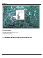
7URXEOHVKRRWLQJ
3UHFDXWLRQVEHIRUH3HUIRUPLQJ,QVSHFWLRQRU5HSDLU
&RQ¿UPDWLRQ
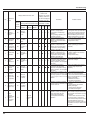
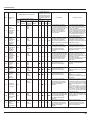
-XGJHPHQWE\)ODVKLQJ/('RI,QGRRU2XWGRRU8QLW
+RZWR&KHFN6LPSO\WKH0DLQ3DUW
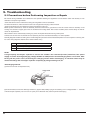
5HPRYDO3URFHGXUH
5HPRYDO3URFHGXUHRI,QGRRU8QLW
5HPRYDO3URFHGXUHRI2XWGRRU8QLW
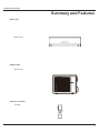
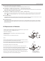
6XPPDU\DQG)HDWXUHV
6XPPDU\DQG)HDWXUHV
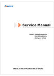
,QGRRU8QLW
TAN-A16 HDI
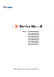
2XWGRRU8QLW
TAG-A16 HDI
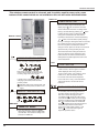
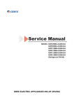
5HPRWH&RQWUROOHU
<$*)%
FAN
MODE
ON/OFF
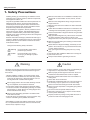
6DIHW\3UHFDXWLRQV
6DIHW\3UHFDXWLRQV
Installing, starting up, and servicing air conditioner can be
hazardous due to system pressure, electrical components,
and equipment location, etc.
Only trained, qualified installers and service personnel are
allowed to install, start-up, and service this equipment.
Untrained personnel can perform basic maintenance functions such as cleaning coils. All other operations should
be performed by trained service personnel.
Make sure the outdoor unit is installed on a stable, level
surface with no accumulation of snow, leaves, or trash
beside.
When handling the equipment, observe precautions in the
manual and on tags, stickers, and labels attached to the
equipment. Follow all safety codes. Wear safety glasses
andwork gloves. Keep quenching cloth and fire extinguisher
nearby when brazing.
Follow all the installation instructions to minimize the risk
of damage from earthquakes, typhoons or strong winds.
Read the instructions thoroughly and follow all warnings or
cautions in literature and attached to the unit. Consult local
building codes and current editions of national as well as
local electrical codes.
Recognize the following safety information:
Warning
Incorrect handling could result in
personal injury or death.
Caution
Incorrect handling may result in
minor injury,or damage to product
or property.
Warning
All electric work must be performed by a licensed technician
according to local regulations and the instructions given in
this manual.
Before installing, modifying, or servicing system, main
electrical disconnect switch must be in the OFF position.
There may be more than 1 disconnect switch. Lock out
and tag switch with a suitable warning label.
Never supply power to the unit unless all wiring and tubing are completed, reconnected and checked.
This system adopts highly dangerous electrical voltage.
Incorrect connection or inadequate grounding can cause
personal injury or death. Stick to the wiring diagram and
all the instructions when wiring.
Have the unit adequately grounded in accordance with
local electrical codes.
Have all wiring connected tightly. Loose connection may
lead to overheating and a possible fire hazard.
Make sure the ceiling/wall is strong enough to bear the
weight of the unit.
Make sure the noise of the outdoor unit does not disturb
neighbors.
Avoid contact between refrigerant and fire as it generates
poisonous gas.
Apply specified refrigerant only. Never have it mixed with
any other refrigerant. Never have air remain in the
refrigerant line as it may lead to rupture and other hazards.
Make sure no refrigerant gas is leaking out when installation is completed.
Should there be refrigerant leakage, the density of refrigerant in the air shall in no way exceed its limited value,
or it may lead to explosion.
Keep your fingers and clothing away from any moving
parts.
Clear the site after installation. Make sure no foreign objects are left in the unit.
Always ensure effective grounding for the unit.
Caution
Never install the unit in a place where a combustible gas
might leak, or it may lead to fire or explosion.
Make a proper provision against noise when the unit is
installed at a telecommunication center or hospital.
Provide an electric leak breaker when it is installed in a
watery place.
Never wash the unit with water.
Handle unit transportation with care. The unit should not
be carried by only one person if it is more than 20kg.
Never touch the heat exchanger fins with bare hands.
Never touch the compressor or refrigerant piping without
wearing glove.
Do not have the unit operate without air filter.
Should any emergency occur, stop the unit and disconnect the power immediately.
Properly insulate any tubing running inside the room to
prevent the water from damaging the wall.
All installation or repair work shall be performed by your dealer or a specialized subcontractor as there is the risk of fire,
electric shock, explosion or injury.
6SHFL¿FDWLRQV
6SHFLÀFDWLRQV
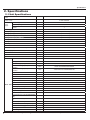
8QLW6SHFLÀFDWLRQV
TAN/TAG-A16 HDI
0RGHO
9̚
&%
&%
+]
3URGXFW&RGH
5DWHG9ROWDJH
3RZHU
6XSSO\
5DWHG)UHTXHQF\
3KDVHV
3RZHU6XSSO\0RGH
&RROLQJ&DSDFLW\0LQ ̚ 0D[
,QGRRU
:
̚ +HDWLQJ&DSDFLW\0LQ ̚ 0D[
:
̚ &RROLQJ3RZHU,QSXW0LQ ̚ 0D[
:
̚ +HDWLQJ3RZHU,QSXW0LQ ̚ 0D[
:
̚ &RROLQJ3RZHU&XUUHQW
$
+HDWLQJ3RZHU&XUUHQW
$
5DWHG,QSXW
:
5DWHG&XUUHQW
$
PK
/K
((5
::
&23
::
$LU)ORZ9ROXPH6++0+00//6/
'HKXPLGLI\LQJ9ROXPH
$SSOLFDWLRQ$UHD
P
0RGHORILQGRRUXQLW
)DQ7\SH
'LDPHWHU/HQJWK';/
)DQ0RWRU&RROLQJ6SHHG6++0+0
0//6/
)DQ0RWRU+HDWLQJ6SHHG6++0+0
0//6/
2XWSXWRI)DQ0RWRU
&URVVÀRZ
PP
ĭ;
UPLQ
UPLQ
:
)DQ0RWRU5/$
$
)DQ0RWRU&DSDFLWRU
ȝ)
,QSXWRI+HDWHU
:
(YDSRUDWRU)RUP
3LSH'LDPHWHU
,QGRRU8QLW5RZ¿Q*DS
&RLO/HQJWK/;';:
$OXPLQXP)LQFRSSHU7XEH
PP
ĭ
PP
PP
;;
6ZLQJ0RWRU0RGHO
TAN-A16 HDI
039&03$$
2XWSXWRI6ZLQJ0RWRU
:
)XVH
6RXQG3UHVVXUH/HYHO6++0+00/
/6/
6RXQG3RZHU/HYHO6++0+00//
6/
'LPHQVLRQ:;+;'
$
G%$
G%$
PP
;;
'LPHQVLRQRI&DUWRQ%R[/;:;+
PP
;;
'LPHQVLRQRI3DFNDJH/;:;+
PP
;;
1HW:HLJKW
NJ
*URVV:HLJKW
NJ
7KHDERYHGDWDLVVXEMHFWWRFKDQJHZLWKRXWQRWLFH3OHDVHUHIHUWRWKHQDPHSODWHRIWKHXQLW
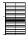
Outdoor Unit Model
--
Compressor Trademark
TAG-A16HDI
MITSUBISHI
Compressor Manufacturer
--
MITSUBISHI ELECTRIC <GUANGZHOU>COMP
Compressor Model
--
SNB130FGYMC-L1
Compressor Oil
--
FV50S
Compressor Type
--
Rotary
Compressor LRA.
A
27.00
Compressor RLA
A
8.40
Compressor Power Input
W
1245
Compressor Overload Protector
--
1NT11L-6578
Fan Type
--
Axial-flow
Fan Diameter
mm
㩪520
Fan Motor Speed
rpm
700 / 500
Fan Motor Power Output
W
60
Fan Motor RLA
A
/
Fan Motor Capacitor
Outdoor Unit Air Flow Volume
Condenser Form
ȝF
/
m3/h
3200
--
Aluminum Fin-copper Tube
Condenser Pipe Diameter
mm
ij7
Condenser Rows-fin Gap
mm
3-1.4
Condenser Coil Length (L×D×W)
mm
823.5×649×38.1
MPa
4.3
MPa
2.5
MPa
4.3
Cooling Operation Ambient Temperature Range
Ԩ
10㨪48
Heating Operation Ambient Temperature Range
Ԩ
-15㨪24
Throttling Method
--
Electron expansion valve
Defrosting Method
--
Automatic Defrosting
Climate Type
--
T1
Outdoor Unit
Permissible Excessive Operating Pressure for the
Discharge Side
Permissible Excessive Operating Pressure for the
Suction Side
Maximum Allowable Pressure
Isolation
--
I
Moisture Protection
--
IP24
Sound Pressure Level
dB (A)
56/50
Sound Power Level
dB (A)
66/60
Dimension (W×H×D)
mm
955 ×700×396
Dimension of Carton Box (L×W×H)
mm
1026×455×735
Dimension of Package(L×W×H)
mm
1029×458×750
Net Weight
kg
50.0
Gross Weight
kg
55.0
Refrigerant
--
R410A
Refrigerant Charge
kg
1.60
Length
m
5
g/m
50
mm
ij6
mm
ij16
Max Distance Height
m
10
Max Distance Length
m
25
Gas Additional Charge
Connection Outer Diameter Liquid Pipe
Pipe
Outer Diameter Gas Pipe
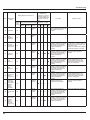
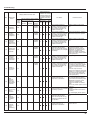
6SHFL¿FDWLRQV
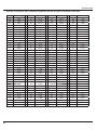
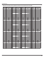
2SHUDWLRQ'DWD
&RROLQJ
7HPSHUDWXUHFRQGLWLRQ
&
6WDQGDUG
+HDWH[FKDQJHUSLSHWHPS ,QGRRUIDQ 2XWGRRUIDQ &RPSUHVVRU
SUHVVXUH
PRGHUSP PRGHUSP UHYROXWLRQUSV
303D
7&
7&
LQa
LQa
a
RXWa
RXWa
LQa
LQa
a
RXWa
RXWa
0RGHOQDPH
,QGRRU
2XWGRRU
.
.
+HDWLQJ
7HPSHUDWXUHFRQGLWLRQ
&
0RGHOQDPH
6WDQGDUG
SUHVVXUH
303D
+HDWH[FKDQJHUSLSHWHPS ,QGRRUIDQ 2XWGRRUIDQ &RPSUHVVRU
PRGHUSP PRGHUSP UHYROXWLRQUSV
7&
7&
,QGRRU
2XWGRRU
.
a
LQa
RXWa
LQa
RXWa
.
a
LQa
RXWa
LQa
RXWa
127(6
7,QOHWDQGRXWOHWSLSHWHPSHUDWXUHRIHYDSRUDWRU
7,QOHWDQGRXWOHWSLSHWHPSHUDWXUHRIFRQGHQVHU
33UHVVXUHRIDLUSLSHFRQQHFWLQJLQGRRUDQGRXWGRRUXQLWVRQWKHVLGHRIJDVSLSH
0HDVXUHVXUIDFHWHPSHUDWXUHRIKHDWH[FKDQJHUSLSHDURXQGFHQWHURIKHDWH[FKDQJHUSDWK8EHQW
7KHUPLVWRUWKHPRPHWHU
&RQQHFWLQJSLSLQJFRQGLWLRQP
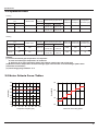
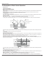
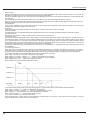
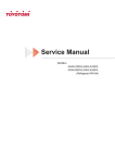
1RLVH&ULWHULD&XUYH7DEOHV
60
50
58
Heating
Noise/dB(A)
Noise dB(A)
56
54
Cooling
52
40
30
50
48
46
20
20
30
40
50
60
70
80
Compressor frequency(Hz)
90
100
SL
L
ML
M
H
SH
Indoor fan motor rating speed
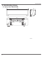
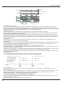
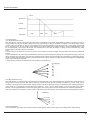
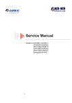
&RQVWUXFWLRQ9LHZV
&RQVWUXFWLRQ9LHZV
,QGRRU8QLW TAN-A16 HDI
1018
319
230
144
189
685
Φ70
Φ70
55
119
55
13
44
8QLWPP
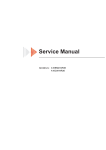
&RQVWUXFWLRQ9LHZV
2XWGRRU8QLW TAG-A16 HDI
340
700
963
890
396
364
560
Unit:mP
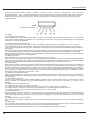
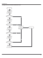
5HIULJHUDQW6\VWHP'LDJUDP
5HIULJHUDQW6\VWHP'LDJUDP
&RROLQJ& Heating0RGHOV
INDOOR UNIT
OUTDOOR UNIT
GAS SIDE
3-WAY VALVE
4-Way valve
Discharge
HEAT
EXCHANGE
(EVAPORATOR)
Suction
Accumlator
COMPRESSOR
HEAT
EXCHANGE
(CONDENSER)
LIQUID SIDE
2-WAY VALVE
Strainer
Electron expansion valve Strainer
COOLING
HEATING
5HIULJHUDQWSLSHGLDPHWHU
/LTXLGPP
*DVPP
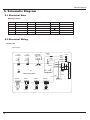
6FKHPDWLF'LDJUDP
6FKHPDWLF'LDJUDP
(OHFWULFDO'DWD
0HDQLQJRIPDUNV
6\PERO
&RORUV\PERO
:+
:+,7(
<(
97
&RORUV\PERO
6\PERO
*1
*5((1
6$7
<(//2:
%1
%52:1
&203
5('
%8
%/8(
<(//2:*5((1
9,2/(7
%.
%/$&.
2*
25$1*(
5'
<(*1
6\PERO
3DUWVQDPH
29(5/2$'
&2035(6625
3527(&7,9(($57+
(OHFWULFDO:LULQJ
Ɣ,QGRRU8QLW
TAN-A16 HDI
ROOM
TEMP.SENSOR
RECEIVER AND
DISPLAY BOARD
TUBE
TEMP.SENSOR
MAGNETIC
RING
L
AP1
0
POWER
BN(BK)
L
0
RT2
RT1
L
BU(WH)
N
YEGN(GN)
XT1
ROOM
TUBE
CAP
JUMP
DISP1
AP2
N
COM-OUT
DISP2
M1
FAN
MOTOR
M2
SWING
MOTOR(L.R)
2
W3BN
3
L-OUT
AC-L
K7
PRINTED CIRCUIT BOARD
SWING-LR
W2BK
SWING-UD1
M3
SWING
MOTOR(U.D1)
SWING-UD2
M4
SWING
MOTOR(U.D2)
BU
BK
BN
YEGN
TERMINAL
BOARD
PE
DC-MOTOR
N(1)
W4YEGN
YEGN
PE
EVAPORATOR
OUTDOOR UNIT
W1BU
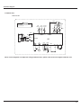
6FKHPDWLF'LDJUDm
Ɣ2XWGRRU8QLW
TAN-A16 HDI
4WH
5WH
WARNING
Please don't touch any terminal when the
voltage of terminal P(DC+) and N(DC-) at
AP1 is higher than 30V to prevent the risk
of electrical shock!
OUTROOM
TEM.SENSOR
OUTTUBE
TEM.SENSOR
RT2
0
RT1
0
DISCHARGE
TEM.SENSOR
WH
YEGN
INDOOR UNIT
YEGN
BU
PE
XT
N(1)
BK
2
BK
BN
3
BN
YE
T-SENSOR
L1
S(W,X)
C(T,U)
L2
PE
2BU
BU
COMP-U
PE
BU
BK
PE
COMP.
COMP E 6YEGN
L2
1YE
L2
RT3
0
SAT
R(M,V)
3RD
X1
RD
COMP-V
COMP-W
OVC-COMP
N
L1
COM-INNER
AP1
AC-L
FA
4V
HALL
OFAN
INDC1
INDC2 PFCC1
PFCC2
YE
OG YE
WH
4YV
M
EKV
FAN
MOTOR
C
YEGN
PE
L
7KHVHFLUFXLWGLDJUDPVDUHVXEMHFWWRFKDQJHZLWKRXWQRWLFHSOHDVHUHIHUWRWKHRQHVXSSOLHGZLWKWKHXQLW
17
6FKHPDWLF'LDJUDP
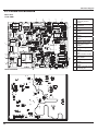
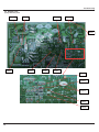
3ULQWHG&LUFXLW%RDUG
,QGRRU8QLW
Ɣ7239,(:
5
6
7
8
9
10
4
3
2
11
1
Ɣ%277209,(:
14
13
12
,QGHSHQGHQWYHQWLODWHG
FRQWUROUHOD\.DQG
WHUPLQDO
+HDOWK\FRQWUROOHUUHOD\.
DQGWHUPLQDO
)XVH
3RZHUQHXWUDOZLUH
LQWHUIDFH
,QWHUQDOIDQPRWRUFRQWURO
LQWHUIDFH
6WDWLFGHGXVWLQJFRQWURO
LQWHUIDFH
$XWREXWWRQ
8SGRZQVZLQJVPDOO
ORXYHUJXLGHFRQWURO
LQWHUIDFH
/HIWULJKWVZLQJFRQWURO
LQWHUIDFH
8SGRZQVZLQJELJ
ORXYHU
JXLGHFRQWUROOHULQWHUIDFH
'LVSOD\FRQWUROOHULQWHUIDFH
',63',63
$PELHQWWHPSVHQVRU
LQWHUIDFH
7XEHWHPSVHQVRU
LQWHUIDFH
2XWGRRUXQLWSRZHUVXSSO\
FRQWUROUHOD\.
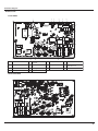
6FKHPDWLF'LDJUDP
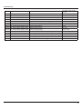
2XWGRRU8QLW
Ɣ7239,(:
1
2
3
4
5
6
7
8
9
10
11
14
13
12
1
Compressor interface
2
Compressor overload
protector
3
Temperature sensor
4
Electric expansion valve
5
Fan HALL interface
6
Outdoor fan
7
4-way valve
8
Communication
with indoor unit
9
Live wire
10
Earthing wire
11
Neutral wire
12
Reactor interface 1
13
PFC capacitor interface 1
14
Reactor interface 2
interface
Ɣ%277209,(:
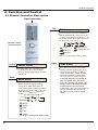
)XQFWLRQDQG&RQWURO
)XQFWLRQDQG&RQWURO
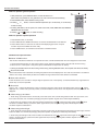
5HPRWH&RQWUROOHU'HVFULSWLRQ
Signal transmitter
FAN
FAN button
Press this button, Auto, Low , Medium-low ,
Medium, Medium-high, High speed can be
circularly selected. After powered on, Auto
fan speed is default. Under DRY mode, Low
fan speed only can be set up.
Remote control
AUTO
Low fan
Medium fan
Medium-low fan
Medium-high fan
High fan
Note: It’s Low fan speed under Dry mode.
ON/OFF
TEMP
ON/OFF button
Press this button, the unit will be turned
on, press it once more, the unit will be
turned off. Sleep function will be canceled,
while unit off.
MODE
MODE button
Press this button, Auto, Cool,Dry, Fan,
Heat mode can be selected circularly.
Auto mode is default while power on.
Under Auto mode,the temperature will not
be displayed; Under Heat mode, th e
initial value is 28 ( 82 oF) ;Under other
modes, the initial value is 25
o
( 77 F) .
AUTO
COOL
DRY
FAN
HEAT
(only for cooling and heating unit)
TEMP button
Press this button, can set up and select:
setting temperature (displaying the room),
indoor ambient temperature (displaying
indoor temperature), outdoor ambient
temperature (displaying outdoor temperature),if there no outdoor ambient
temperature displaying be required that will
keep original display status. and circulate
like this. No signal displayed. Remark: When
operating this button,the setting temperature
is displayed all the time on the wireless
remote control. (There is no this function for
this unit. If press this key, the main unit
will click, but it also runs under original
status. )
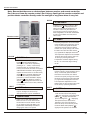
)XQFWLRQDQG&RQWURO
Note: Besure that there are no obstructions between receiver and remote controller;
Don't drop or throw the remote control; Don't let any liquid get into remote controller and
put the remote controller directly under the sunlight or any place where is very hot.
X-FAN
X-FAN button
● Pressing X -FAN button in COOL or DRY
mode,the icon
is displayed and the
indoor fan will continue operation for 10
minutes in order to dry the indoor unit
even though you have turned off the unit.
After energization, X-FAN OFF is defaulted.
X-FAN is not available in AUTO,FAN or
HEAT mode.
Remote control
+
+
button
● Presetting temperature can be increased.
Press this button,the temperature can be
set up, continuously press this button
and hold for two seconds, the relative
contents can quickly change,until unhold
CLOCK
this button and send the order that the
o
( F) signal will be displayed all the time.
The temperature adjustment is unavilable
under the Auto mode, but the order can
be sent by if pressing this button.
Temperature of Celsius degree setting:
16-30 ; for Fahrenheit degree setting:
61-86.
CLOCK button
● Press this button, the clock can be set up,
signal blink and display.Within 5
seconds, the value can be adjusted by
pressing + or - button, if continuously
press this button for 2 seconds above,
in every 0.5 seconds, the value on ten place
of Minute will be increased 1. During blinking,
repress the Clock button or Confirm button,
signal will be constantly displayed and
it denotes the setting succeeded. After
powered on, 12:00 is defaulted to display
and signal will be displayed. If there is
signal
be displayed that denotes the
current time value is Clock value, otherwise
is Timer value.
LIGHT
LIGHT button
● Press this button at unit on or off status,
Light on and light off can be set up.
After powered on, Light on is defaulted.
TURBO
TURBO button
● Under Cool or Heat mode,press this
button can turn on or turn off the Turbo
function.After the Turbo function turned
on, the signal of Turbo will display. The
signal will be automatically cancelled if
changing the mode or fan speed.
-
-
button
● Presetting temperature can be decreased.
Press this button, the temperature can be
set up, continuously press this button
and hold for two seconds, the relative
contents can quickly change,until unhold
this button and send the order that the
o
( F) signal will be displayed all the time.
The temperature adjustment is unavailable under the Auto mode,but the order
can be sent by if pressing this button.
QUIET
QUIET button
● Press this button,the Quiet status is
under the Auto Quiet mode (display
"
" and “Auto”signal ) and Quiet mode
(display " " singal) and Quiet OFF
(there is no signal of "
" displayed),
after powered on,the Quiet OFF is
defaulted. Note: the Quiet function
cannot be set up in Fan and Dry mode;
Under the Quiet mode (Display "
"
signal), the fan speed is not available.
)XQFWLRQDQG&RQWURO
This wireless remote control is universal, and it could be used for many units, some
buttons of this control which are not available to this unit will not be described below.
TIMER ON
TIMER ON BUTTON
● Timer On setting: Signal “ON”will blink and
display,signal
will conceal,the numerical
section will become the timer on setting status.
During 5 seconds blink,by pressing or button
to adjust the time value of numerical section,
every press of that button,the value will be
increased or decreased 1 minute.Hold pressing
or button,2 seconds later,it quickly change,
the way of change is: During the initial 2.5 seconds,
ten numbers change in the one place of minute,
then the one place is constant,ten numbers
change in the ten splace of minute at 2.5 seconds
speed and carry. During 5s blink,press the
Timer button,the timer setting succeeds.The
Timer On has been set up,repress the timer
button,theTimer On will be canceled. Before
setting theTimer,please adjust the Clock to the
Remote control
SWING UP AND DOWN BUTTON
current actual time.
● Press this bu tt on to set swing angle,
which circ ul arly chang es as below :
I FEEL
I FEEL BUTTON
● Press this button once, to turn on the
OFF
I FEEL function , then the figure of "I FEEL"
will be displayed, after every press of
other function button, every 200ms to send
I FEEL once, after this function started,
the remote control will send temperature
to the main un it in every 10 minutes.When
This remote controller is universal. If it
receives threes kinds of following status,
the swing angle will remain origial.
If guide louver is stopped when it is
swinging up and down,it will remain its
present position.
indicates guide louver swings back and
forth in the five places,as shown in the
figure.
SWING LEFT AND RIGHT BUTTON
●
Press this button to set left & right swing angle
cycling as below:
OFF
TIMER OFF
TIMER OFF button
● One press this key to enter into TIMER
OFF setup, in which case the TIMER OFF
icon will blink. The method of setting is the
sameas for TIMER ON.
repress this button, this function will be
turned off.
/
HEALTHY AND SCAVENGING BUTTON
● Press this button to achieve the on and
off of healthy and scavenging functions in
operation status.Press this button for the
first time to start scavenging function;
LCD displays“
”.Press the button for the
second time to start healthy and scavenging
functions simultaneously;LCD displays“ ”
and “ ” . Press this button for the third
time to quit healthy and scavenging functions
simultaneously.Press the button for the
fourth time to start healthy function; LCD
display“
” .Press this button again to
repeat the operation above.
)XQFWLRQDQG&RQWURO
●
Press this button, can select Sleep 1 (
Sleep 3 (
), Sleep 2 (
),
) and cancel the Sleep, circulate between
these, after electrified, Sleep Cancel is defaulted.
●
Sleep 1 is Sleep mode 1, in Cool, Dehumidify modes: sleep status
after run for one hour , the main unit setting temperature will
increase 1 ,setting temperature increased 2
, the unit will
run at this setting temperature; In Heat mode: sleep status after run
for one hour , the setting temperature will decrease 1
, 2
hours , setting temperature will decrease 2 , then the unit will
run at this setting temperature.
●
Sleep 2 is sleep mode 2, that is air conditioner will run according to
the presetting a group of sleep temperature curve.
In Cool mode:
(1) When setting the initial temperature 16-23
, after turned on
Sleep function, the temperature will be increased 1
after 3
in every hour,
the temperature will be maintained, after 7hours,
the temperature will be decreased 1 , after that the unit will keep on
running under this temperature;
27
(2) When setting the initial temperature 24
on Sleep function, the temperature will be increased 1
SLEEP
SLEEP BUTTON
after 2
, after turned
in every hour ,
the temperature will be maintained, after 7hours,
the temperature will be decreased 1 , after that the unit will
keep on running under this temperature;
(3) When setting the initial temperature 28
29 , after turned
on Sleep function, the temperature will be increased 1
hour, after 1
in every
the temperature will be maintained, after 7hours ,
the temperature will be decreased 1 , after that the unit will
keep on running under this temperature;
(4) When setting the initial temperature 30
, under this temper-
ature setting, after 7hours, the temperature will be decreased
1 , after that the unit will keep on running under this temperature;
In Heat mode:
(1) Under the initial presetting temperature 16
, it will run under
this setting temperature all along.
(2) Under the initial presetting temperature17
20 , after Sleep
function started up, the temperature will decrease 1
hour, after 1
in every
decreased, this temperature will be maintained.
)XQFWLRQDQG&RQWURO
(3) Under the initial presetting temperature 21
function started up, the temperature will decrease 1
after 2
27 , after Sleep
in every hour,
decreased, this temperature will be maintained.
(4) Under the initial presetting temperature 28
30
, after
Sleep function started up, the temperature will decrease 1
every hour, after 3
●
in
decreased, this temperature will be maintained.
Sleep 3- the sleep curve setting under Sleep mode by DIY:
(1) Under Sleep 3 mode, press "Turbo" button for a long time, remote
control enters into user individuation sleep setting status, at this
time, the time of remote control will display "1hour ", the setting
temperature "88" will display the corresponding temperature of last
setting sleep curve and blink (The first entering will display
according to the initial curve setting value of original factory);
-
(2) Adjust " + " and "
" button, could change the corresponding
setting temperature, after adjusted, press "Trubo "button for
confirmation;
(3) At this time, 1hour will be automatically increased at the timer
postion on the remote control, (that are "2hours" or "3hours "
or "8hours "), the place of setting temperature "88" will
SLEEP
display the corresponding temperature of last setting sleep curve
SLEEP BUTTON
and blink;
(4) Repeat the above step (2 )
(3) operation, until 8hours
temperature setting finished, sleep curve setting finished, at this
time, the remote control will resume the original timer display;
temperature display will resume to original setting temperature.
●
Sleep3- the sleep curve setting under Sleep mode by DIY could
be inquired:
The user could accord to sleep curve setting method to inquire
the presetting sleep curve, enter into user individuation sleep
setting status, but do not change the temperature, press "Turbo"
button directly for confirmation.
Note: In the above presetting or enquiry procedure, if continuously
within10s, there is no button pressed, the sleep curve setting
status will be automatically quit and resume to display the original
displaying. In the presetting or enquiry procedure, press "ON/OFF"
button, "Mode" button, "Timer"button or "Sleep" button, the sleep
curve setting or enquiry status will quit similarly.
)XQFWLRQDQG&RQWURO
Guide for operation- general operation
1
4
2
1. After powered on, press ON/OFF button, the unit will start to run.
3
(Note: When it is powered on, the guide louver of main unit will close automatically.)
2. Press MODE button, select desired running mode.
3. Pressing
+
or
-
5
button, to set the desired temperature (It is unnecessary to set the temp.
at AUTO mode.)
4. Pressing FAN button, set fan speed, can select AUTO FAN, LOW, MEDIUM-LOW, MEDIUM,
MEDIUM-HIGH and HIGH.
5. Pressing
and
button, to select the swing.
Guide for operation- Optional operation
1. Press SLEEP button, to set sleep.
2. Press TIMER ON and TIMER OFF button, can set the scheduled timer on or timer off.
4
2
3. Press LIGHT button, to control the on and off of the displaying part of the unit (This
function may be not available for some units).
3
1
4. Press TURBO button, can realize the ON and OFF of TURBO function.
Introduction for special function
ƾ About X-FAN function
This function indicates that moisture on evaporator of indoor unit will be blowed after the unit is stopped to avoid mould.
1. Having set X-FAN function on: After turning off the unit by pressing ON/OFF button indoor fan will continue running
for about 10 min. at low speed. In this period, press X-FAN button to stop indoor fan directly.
2. Having set X-FAN function off: After turning off the unit by pressing ON/OFF button, the complete unit will be off directly.
ƾ About AUTO RUN
When AUTO RUN mode is selected, the setting temperature will not be displayed on the LCD, the unit will be in accordance
with the room temp. automatically to select the suitable running method and to make ambient comfortable.
ƾ About turbo function
If start this function, the unit will run at super-high fan speed to cool or heat quickly so that the ambient temp. approachs the
preset temp. as soon as possible.
ƾ About lock
Press + and - buttons simultaneously to lock or unlock the keyboard. If the remote controlleris locked, the icon
will be
displayed on it, in which case, press any button, the mark will flicker for three times. If the keyboard is unlocked, the mark will
disappear.
ƾ About swing up and down
1. Press swing up and down button continuously more than 2s,the main unit will swing back and forth from up to down, and
then loosen the button, the unit will stop swinging and present position of guide louver will be kept immediately.
2. Under swing up and down mode, when the status is switched from off to , if press this button again 2s later,
status
will switch to off status directly; if press this button again within 2s,the change of swing status will also depend on the
circulation sequence stated above.
ƾ About swing left and right
1. Press swing left and right button continuously more than 2s,the main unit will swing back and forth from left to right, and then
loosen the button, the unit will stop swinging and present position of guide louver will be kept immediately.
2. Under swing left and right mode, when the status is switched from off to
, if press this button again 2s later,
status will
switch to off status directly; if press this button again within 2s,the change of swing status will also depend on the circulation
sequence stated above.
)XQFWLRQDQG&RQWURO
ƾAbout switch between Fahrenheit and Centigrade
Under status of unit off, press MODE and - buttons simultaneously to switch ºC and ºF .
ƾCombination of " TEMP" and "CLOCK" buttons : About Energy-saving Function
Press “TEMP” and “CLOCK” simultaneously in COOL mode to start energy-saving function.Nixie tube on the remote controller
displays “SE”. Repeat the operation to quit the function.
ƾCombination of " TEMP" and "CLOCK" buttons : About 8℃ Heating Function
Press “TEMP” and “CLOCK” simultaneously in HEAT mode to start 8℃ Heating Function.Nixie tube on the remote controller
displays “ ” and a selected temperature of “8℃” (46℉if Fahrenheit is adopted). Repeat the operation to quit the function.
ƾAbout Quiet function
If Auto Quiet mode has been selected, after the room temperature reached the setting temperature or 10mins later, the AC will
immediately enter into the Quiet running status, at this time the fan speed is not adjustable.
ƾAbout Sleep function
Under the Fan and Auto mode, the Sleep function cannot be set up, under Dehumidify mode, only Sleep 1 can be selected.
Select and enter into any kind of Sleep mode, the Quiet function will be attached and stared, different Quiet status could be
optional and turned off.
5HSODFHPHQWRI%DWWHULHV
1.Slightly to press the place with
, along the arrowhead direction to push the back
cover of wireless remote control.(As show in Fig 1. )
2.Take out the old batteries.
Fig.1
2
3.Insert two new AAA1.5V dry batteries, and pay attention to the polarity.
(As show in Fig 2.)
1
4. Attach the back cover of wireless remote control.
NOTE:
● When changing the batteries, do not use the old or different batteries, otherwise,
it can cause the malfunction of the wireless remote control.
● If the wireless remote control will not be used for along time, please take them out,
and don't let the leakage liquid damage the wireless remote control.
Fig.2
3
● The operation should be in its receiving range.
● It should be placed where is 1m away from the TV set or stereo sound sets.
4
● If the
remote control cannot operate normally, please take the batteries out, and
then reinsert it 30s later; if it is also abnormal ,please replace the batteries.
● If the main unit needs to be remote controlled, please aim remote controller at the
receiver of main unit in order to improve the receiving sensitivity of the main unit.
● When the remote controller sends out signal, a mark
The bell will ring if the main unit receives effective signal.
will flicker for about 1s.
Sketch map for
changing batteries
)XQFWLRQDQG&RQWURO
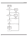
'HVFULSWLRQRI(DFK&RQWURO2SHUDWLRQ
ƽ Indoor Unit
1Temperature Parameters
ƹIndoor preset temperature (Tpreset)
ƹIndoor ambient temperature (Tamb.)
2 Basic functions (The temperature in this manual is expressed by Centigrade. If Fahrenheit is used, the switchover between them is
Tf=TcX1.8+32.)
Once the compressor is energized, there should be a minimum interval of 3 minutes between two start-ups. But if the unit is
de-energized and then energized, the compressor can restart within 3 minutes.
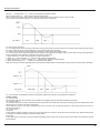
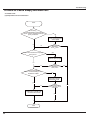
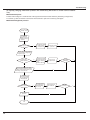
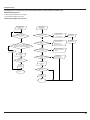
2.1 Cooling mode
2.1.1 Cooling conditions and process
When Tamb. ≥Tpreset, the unit starts cooling operation. In this case, the compressor and the outdoor fan operate and the indoor fan
operates at set speed.
When Tamb. ≤Tpreset-3ć, the compressor and the outdoor fan stop while the indoor fan runs at set speed.
When Tpreset-3ć˘Tamb. ˘Tpreset, the unit will maintain its previous running status.
In cooling mode, temperature setting range is 16̚30ć; the indoor unit displays operation icon, cooling icon and set temperature.
Start cooling
Tamb
Tpreset+1
Original operating status
Tpreset 1
Stop cooling
min.
min.
min.
Compressor
Outdoor fan
Set Fan speed
Indoor fan
Stop
Run
2.1.2 When outdoor unit has malfunction or stops for protection, indoor unit will keep previous operation status and display malfunction
code.
2.1.3 The protection status is as the same as the cooling mode.
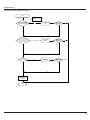
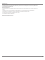
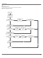
2.2 Dry Mode
2.2.1 Dry Conditions and Process
When Tamb. ˚Tpreset, the unit starts drying and cooling operation. In this case, the compressor and the outdoor fan operate; the
indoor fan operates at low speed.
When Tpreset-3ć≤Tamb. ≤Tpreset, the unit will start drying operation. In this case, the indoor fan operates at low speed; the
compressor and the outdoor fan operate for 6 minutes and stop for 4 minutes in cycle.
When Tamb.˘Tpreset-3ć, the compressor and the outdoor fan stop operation; the indoor fan operates at low speed.
In drying mode, the four-way valve is de-energized; temperature setting range is 16̚30ć; the indoor unit displays operation icon,
drying icon and set temperature.
Tamb.
Cooling
Tpreset+2
Dehumidfying
Tpreset 2
min
.
Stop
min.
min.
min.
Compressor
Outdoor fan
Indoor fan
Low speed
Run
Stop
2.2.2 When outdoor unit has malfunction or stops for protection, indoor unit will keep previous operation status and display malfunction
code.
2.2.3 The protection status is as the same as the cooling mode.
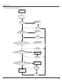
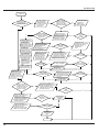
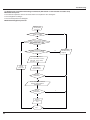
2.3 Heating mode (not available for cooling only type)
2.3.1 Heating conditions and process
When Tamb. ≤Tpreset+2ć, the unit starts heating operation. In this case, compressor and outdoor fan operate simultaneously; the
indoor fan operates at cold-air prevention mode.
When Tamb≥Tpreset+5ć, the compressor and outdoor fan stop operation; the indoor fan blows residual heat.
When Tpreset +2ć˘T amb. ˘ Tpreset +5ć, the unit will maintain its previous running status.
Under this mode, temperature setting range is 16̚30ć; the indoor unit displays operation icon, heating icon and set temperature.
)XQFWLRQDQG&RQWURO
stop heating
Tpreset
original operation status
Tpreset
Tamb.
start heating
min
min
min
Compressor
Outdoor unit
Indoor unit
setting
fan speed
min
min
setting
fan speed
4-way valve
Run
Stop
2.3.2 Defrosting and Oil Return
When receiving the signal of defrosting and oil return, the horizontal louver(big one) will rotate to the position where the angle is
minimum and the other horizontal louver(small one) will close. In 10 seconds later, indoor fan will stop operation. During defrosting, oil
return and 5 minutes after quit, all indoor pipe temperature sensors will not be detected. When receiving oil return signal or defrosting
signal sent by outdoor unit, “dual 8” nixie tube will display “H1”. (H1 is not malfunction code.)
2.3.3 Blow residual heat
In heating mode, when temperature reaches the set temperature, the compressor and outdoor fan will stop.
The horizontal louver (big one) will rotate to the default position for cooling and the other one (small one) will close. Indoor unit will
operate at set speed for 60s and then stop operation.
When the unit is in heating mode or auto heating mode, and also the compressor and indoor fan are operating, if turning off the unit,
compressor and outdoor fan will stop. Horizontal louver (big one) will rotate to the position where gentle wind is blown out (default
position for cooling) and the other horizontal louver (small one) will close. Indoor unit will operate at low speed for 10 seconds and then
the unit will be turned off.
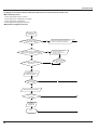
2.4 Fan Mode
In this mode, indoor fan operates at set speed while compressor and outdoor fan stop operation. The set temperature range is
16~30ć. Operation icon and set temperature are displayed.
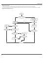
2.5 Auto Mode
In this mode, operation mode (Cool, Heat, Fan) will be automatically selected according to change of ambient temperature. Operation
icon, actual operation icon and set temperature will be displayed. There is 30s delay for protection when changing mode. The
protection function is as the same as that under each mode.
2.5.1 When Tamb.≥26ćˈthe unit will operate at cooling mode, the default set temperature is 25ć.
2.5.2 When Tamb. ≤21ćˈthe unit will operate at heating mode, the default set temperature is 20ć˄if the cooling only unit operates at
fan mode, the default set temperature is 25ć.˅;
2.5.3 When 22 ć ≤Tamb. ≤25ćˈand the unit is turned on for the first time, if it changes to auto mode from other mode, the previous
operation mode will be maintained; If it changes to auto mode from dry mode, the unit will operate at fan mode.
2.5.4 When the unit operates at auto mode, the frequency of compressor is as the same as that under cooling mode, while it is as the
same as that under heating mode.
Protection function
A. Under cooling mode, the protection function is as the same as that under cooling mode.
B. Under heating mode, the protection function is as the same as that under heating mode.
Heating mode Tpreset
=20ć (if cooling-only
unit, it is Fan mode,
Tpreset=25ć˅
Keep current
Cooling mode,
operation mode
Tpreset=25ć
Tpreset
2.6. “8ć” Heating
Under heating mode, press buttons “Temp” and “Clock” simultaneously, the 8ć heating function will be activated and “cold air
prevention” will be shielded.
2.6.1 8 ć heating can’t co-exist with sleep function. If 8ćheating function is set, it can be cancelled by pressing sleep button, In that
case, the set temperature will be that before entering 8 ć heating; If sleep function is set, press buttons “Temp” and “Clock”
simultaneously to activate 8ć function and cancel sleep function at the same time.
2.6.2 Set temperature is 8 ćˈand it is displayed on the indoor display panel.
2.6.3 In this mode, TURBO can’t be set and fan speed can’t be adjusted.
2.6.4 In this mode, when compressor operates, fan speed will be adjusted as follows; when compressor stops operation, indoor unit
will operate at blowing residual heat.
When Tindoor amb. ≤9ć, indoor unit will operate at high speed;
)XQFWLRQDQG&RQWURO
When 9ć ˘Tindoor amb.˘11ć, indoor unit will operate at medium speed;
When Tindoor amb.≥11ćˈindoor fan will operate at low speed;
When changing among low high, medium, and low speeds, the minimum operation time is 210 seconds.
2.6.5 If the unit has memory function, 8ćheating function will be memorized.
Tamb.
Fan speed
Low
High
Med.
2.7 Energy-saving Function
2.7.1 In cooling mode, when receiving command of energy-saving sent by remote control, the controller enters energy-saving mode; If
the unit is under energy-saving mode already, such command will not be executed.
2.7.2 When remote control is set to display set temperature, “dual 8”nixie tube displays “SE”.
2.7.3 In this mode, when compressor operates, fan speed will be adjusted according to auto fan mode under energy-saving operation;
when compressor stops operation, indoor fan will operate at low speed.
a. When Tamb.≥31ć, indoor fan will operate at super high speed;
b. When 31ć˚Tamb.≥Tpreset + 3ć, indoor fan will operate at high speed;
c. When Tpreset+1ć˘Tamb.˘Tpreset + 3ćˈindoor fan will operate at medium speed;
d. When Tamb.≤Tpreset + 1ćˈ indoor fan will operate at low speed;
Note: The switchover among superhigh speed, high speed, medium speed and low speed requires minimum 210seconds of operation.
Tamb.
Tpreset + 3 ć
Tpreset + 1ć
Fan speed
Super high
High
Med.
Low
2.7.4 In this mode, set temperature will be automatically adjusted according to actual operation conditions.
3 Other Control
3.1 Timer function
General timer and clock timer functions are compatible by equipping remote controller with different functions.
3.1.1 General Timer
Timer ON can be set at unit OFF. If selected ON time is reached, the unit will start to operate according to previous setting status. Time
setting range is 0.5-24hr in 30-minute increments.
Timer OFF can be set at unit ON. If selected OFF time is reached, the unit will stop operation. Time setting range is 0.5-24hr in
30-minute increments.
3.1.2 Clock Timer
Timer ON
If timer ON is set during operation of the unit, the unit will continue to operate. If timer ON is set at unit OFF, upon ON time reaches the
unit will start to operate according to previous setting status.
Timer OFF
If timer OFF is set at unit OFF, the system will keep standby status. If timer OFF is set at unit ON, upon OFF time reaches the unit will
stop operation.
)XQFWLRQDQG&RQWURO
Timer Change
Although timer has been set, the unit still can be turned on/off by pressing ON/OFF button of the remote controller. You can also set
the timer once again, and then the unit will operate according to the last setting.
If timer ON and timer OFF are set at the same time during operation of the unit, the unit will keep operating at current status till OFF
time reaches.
If timer ON and timer OFF are set at the same time at unit OFF, the unit will keep off status till ON time reaches.
Each day in future, the system will operate according to preset mode till OFF time reaches and stop operation till ON time reaches. If
ON time and OFF time are the same, OFF command will prevail.
3.2 Auto Button
If this button is pressed, the unit will operate in AUTO mode and indoor fan will operate at auto speed; meanwhile, the swing motor
operates. Press this button again to turn off the unit.
3.3 Buzzer
Upon energization or availably operating the unit or remote controller, the buzzer will give out a beep.
3.4 Sleep Function
In SLEEP mode, the unit will automatically select appropriate sleep curve to operate according to different temperature setting.
3.5 Turbo Function
This function can be set in cooling or heating mode to quickly cool or heat the room.
3.6 X-FAN Function
3.6.1 When the unit is operating at COOL or DRY mode( it is not available under AUTO, HEAT, FAN modes), the X-FAN function can
be turned on/off. When it is turned on,once pressing ON/OFF button to turn off the unit, indoor fan will continue operation at low speed
for 10 minutes. Within the 10 minutes, horizontal louver will keep its previous status while cold plasma and static dedusting will be
forced to be turned on and other loads will be turned off. Then the complete unit will be turned off; When X-FAN function is set to be off,
once pressing ON./OFF button, the complete unit will be turned on immediately.
3.6.2 During X-FAN operation, press X-FAN button, the indoor fan, horizontal louver, cold plasma and static-dedusting will be turned
off immediately.
3.7 Control of Indoor Fan
Indoor fan can be set by remote control within the range of Mute, Fan speed 1, Fan speed 2, Fan speed 3, Fan speed 4, Fan speed 5
and Turbo and Fan will operate at low, med. high or super high speed accordingly. And also, auto fan speed can be set. Under auto
fan speed mode, indoor fan will automatically select high, med., low or mute speed according to change of ambient temperature.
3.7.1 Under Auto Heat mode or regular Heat mode, auto fan speed will be as follows:
When Tamb.˘Tpreset-3ć, indoor fan will operate at high speed;
When Tpreset-3ć≤Tamb.˘Tpreset + 2ćˈ indoor fan will operate at med. speed;
When Tpreset + 2ć≤Tamb.˘Tpreset + 4ć, indoor fan will operate at low fan speed;
When Tamb≥Tpreset + 4ćˈ indoor fan will operate at mute.
Control Diagram of Auto Fan Speed under HEAT Mode
Tamb.
Tpreset +4ć
Tpreset +2ć
Tpreset -3ć
Fan speed
Mute
Low
Med.
High
3.7.2 Under FAN or COOL mode: if it is auto cooling mode or regular cooling mode, auto fan speed will be as follows:
When Tamb. ≥ Tpreset + 3 ć, indoor fan will operate at high speed;
When Tpreset ˘Tamb.˘Tpreset + 3ćˈindoor fan will operate at med. speed;
When Tpreset-2ć˘Tamb.≤Tpreset, indoor fan will operate at low speed;
When Tamb.≤Tpreset-2 ćˈ indoor fan will operate at mute;
3.7.3 There is no auto fan speed under DRY mode
Note: Fan speed “High”, “Med.” and “Low” are respectively corresponding to “Fan speed 5”, “Fan speed 3” and “Fan speed 1”. There is
210 seconds delay for fan speed switchover of auto fan.
)XQFWLRQDQG&RQWURO
Tamb.
Tpreset +3 ć
Tpreset
Tpreset -2 ć
High
Med.
Low
Fan speed
Mute
3.8 Vertical Swing
3.8.1 Small Horizontal Louver
After energization, vertical swing motor will firstly have the horizontal louver rotate anticlockwise to position O to close air outlet. If
swing function has not been set after startup of the unit, horizontal louver will turn clockwise to position D1 in HEAT mode. If swing
function is set when starting up the unit, the horizontal louver will swing between O and D1.There are 7 swing status of horizontal
louver: Positions O, A1, B1, C1 and D1, swing between O and D1 and stop at any position between L and D (angles between O and
D1 are equiangular). Upon turning off the unit, the horizontal louver will close at position O. Swing function is available only when
swing function is set and indoor fan is operating.
Note:
a. If the position is set between O and D1, A 1and C1 or B1 and D1 by remote controller, the horizontal louver will swing between O
and D1.
b. For model 9K/12K, only when big horizontal louver rotates to the second position for heating( 62°of corresponding angle), this louver
will be activated; For 18K model, only when big horizontal louver rotates to the first position for heating(64°of corresponding angle),
this louver will be activated; For 24K mode, only when big horizontal louver rotates to the first position for heating(40°of corresponding
angle), this louver will be activated.
c. Under cooling mode, this horizontal louver will be always in the position O.
(0 degree)
3.8.2 Big Horizontal Louver
After energization, up & down swing motor will firstly have the horizontal louver rotate anticlockwise to position O to close air outlet. If
swing function has not been set after startup of the unit, horizontal louver will turn clockwise to position D in HEAT mode, or turn
clockwise to level position L in other modes. If swing function is set when starting up the unit, the horizontal louver will swing between L
and D.There are 7 swing status of horizontal louver: Positions L, A, B, C and D, swing between L and D and stop at any position
between L and D (angles between L and D are equiangular). Upon turning off the unit, the horizontal louver will close at position O.
Note: If the position is set between L and B, A and C or B and D by remote controller, the horizontal louver will swing between L and D.
(0 degree)
3.9 Horizontal Swing
Upon energization, the vertical louver will be reset to the start position firstly and then stop in the middle position. When setting
)XQFWLRQDQG&RQWURO
horizontal swing, there are 7 status: Position ķ, Position ĸ, Position Ĺ, Positon ĺ, Position Ļ, swing between ķ and Ļ and stop at
any position between ķand Ļ. If setting horizontal swing during operation of the unit, the horizontal swing motor will drive the louver
to swing horizontally. When cancelling horizontal swing or it is not set when turning on the unit, the louver will stop in the current
position and it will not move when turning off the unit. Only when swing is set and indoor fan is operating, the vertical louver can
horizontally swing.
This position is start point
3.10 Display
3.10.1 Operation and Mode Icons
Upon energization, the unit will display all icons within 3 seconds. Under standby state, LED lamp of standby is on. If the unit is turned
on by remote controller, LED lamp of operation is on; meanwhile, the mark of current running mode will be displayed. If the light button
is turned off, no mark will be displayed.
3.10.2 Display of Nixie Tube on Indoor Unit
When energized & started for the first time, the indoor unit defaults to displaying current set temperature (16̚30ć). When set
temperature display is set by remote controller, it will display set temperature; when room temperature display is set, it will display
room or outdoor temperature. After that, when operating the remote controller for other settings, the temperature display method will
keep original.
When operating the remote controller during room temperature display, the set temperature will be displayed for 5 seconds firstly and
then room temperature display returns. If there is malfunction, corresponding malfunction code will be displayed. For example, if
ambient temperature sensor has malfunction, “F1” will be displayed; if indoor pipe temperature has malfunction, “F2” will be displayed;
if jumper cap has malfunction, “C5” will be displayed.
3.11 Memory Function
Memorized items: mode, up & down swing, light, set temperature and set fan speed.
When power is recovered after power failure, the unit will automatically start operation according to memorized status. After power
recovery, the unit without timer setting before power failure will operate according to the last setting; the unit with general timer setting
which has not been fulfilled before power failure will memorize the timer setting and re-calculate the time after.
3.12 I FEEL function
When I FEEL command is received by controller, and also the ambient temperature is received from remote control, the controller will
operate according to the ambient temperature sent by the remote controller (For cold blow prevention, the unit operates according to
the ambient temperature sensed by the air conditioner). The remote controller will send ambient temperature data to the controller for
every 10 minutes. When the data has not been received for 11 minutes, the unit will operate according to the temperature sensed by
the air conditioner. If I FEEL function is not selected, the ambient temperature will be that sensed by the air conditioner. Ambient
temperature of I FEEL displayed by controller is 1ć~59ć.
3.13 Health and Cold Plasma Function
When the unit is operating, turn health or cold plasma to be ON/OFF by health button in remote control (if there is no such button in
remote control, the health is on as default). Only when health or cold plasma is turned on and indoor fan is operation, such function
can be activated.
3.14 Static Dedusting Function
When the unit is operating, turn static dedusting ON/OFF by health button in remote control (if there is no such button in remote
control, the health is on as default). Only when static dedusting is turned on and indoor fan is operation, such function can be
activated.
3.15 Independent Air Exchange Function
3.15.1 Press air button to keep air exchanger operating.
3.15.2 Press air button again to de-energize the air exchanger and the air exchange function is turned off;
3.15.3 When the unit is turned off by Timer and pressing ON/OFF button, air exchange will be turned off as well.
3.15.4 When the unit is off, the air exchange function can also be set by remote control.
3.16. Fahrenheit Display
Nixie tube displays current set temperature. If remote signal is Fahrenheit, the temperature will be displayed in Fahrenheit. The set
temperature range is 16~30ć˄61~86̧˅. Under Auto mode, in COOL operation and FAN operation, 25ć(77̧) will be displayed,
while in HEAT operation and FAN operation, 20ć(68̧) will be displayed. For cooling-only controller, only 25ć(77̧) will be
displayed.
3.17 Locked protection to Indoor Fan Motor
If the indoor fan motor keeps low rotation speed for a continuous period of time after startup, the unit will stop operation and display
“H6”.
3.18 Mute Mode
3.18.1 Auto Mute: When selecting fan speed of auto mute, the fan speed will be adjusted according to change of ambient temperature;
when temperature meets the requirement of the setting, the unit will operate at lowest speed.
3.18.2 Mute mode: When selecting fan speed of mute, the unit will directly operate at lowest fan speed.
)XQFWLRQDQG&RQWURO
ƽ 2XWGRRU8QLW
1. Compensation function of input parameters
According to the structure of wall-mounting unit, considering the comfortability for operation, indoor ambient temperature when the
compressor is at OFF status is higher than set temperature under heating mode.
2. Control of detecting the availability of parameters
For ensuring the safety and reliability of operation, please insert the outdoor discharge temperature sensor into the corresponding
temperature sensor bushing to make sure that the control system can detect system discharge temperature accurately. Otherwise, the
unit will stop operation and it displays malfunction of discharge temperature sensor (discharge temperature sensor hasn’t been inserted
well), which can only be resumed by pressing ON/OFF button on remote controller. Basic functions:
3. Cooling mode
3.1 Working condition and process for cooling
3.1.1 If compressor is at OFF status, and ǒTpreset-(Tindoor amb.-̲Tindoor amb. compensation of coolingǓ≤0ć, the unit operates in cooling mode;
3.1.2 During cooling operation, if 0ć≤ǒTpreset-(Tindoor amb.-̲Tindoor amb. compensation of coolingǓ<3ć, the unit still operates in cooling mode;
3.1.3 During cooling operation, if 3ć≤ǒTpreset-(Tindoor amb.-̲Tindoor amb. compensation of coolingǓ, the unit stops operation when reaching the
temperature point in cooling.
3.2 Temperature setting range:
3.2.1 If Toutdoor amb.≥Tcooling temperature(low temperature), the temperature setting range is 16-30ć (cooling in room temperature);
3.2.2 If Toutdoor amb.<Tcooling temperature(low temperature), the temperature setting range is 25-30ć. That is: the lower limit of set temperature for
outdoor unit is 25ć.
4. Dry mode
4.1 Working conditioner and process for drying is same as that for cooling mode;
4.2 Temperature setting range is 16-30ć;
5. Fan mode
5.1 Compressor, outdoor fan and 4-way valve are all turned off;
5.2 Temperature setting range is 16-30ć.
6. Heating ode
6.1 Working conditioner and process of heating: (Tindoor amb. is the actual temperature detected by indoor ambient temperature sensor;
̲Tindoor amb. compensation of heating is indoor ambient temperature compensation during heating operation).
6.1.1 If compressor is at OFF status, and ǒTindoor amb. -̲Tindoor amb. compensation of heatingǓ-TpresetǓ≤-1ć, the unit operates in heating mode.
6.1.2 During heating operation, if 0ć≤ǒ(Tindoor amb.- ̲Tindoor amb. compensation of heating)-TpresetǓ<2ć, the unit still operates in heating mode.
6.1.3 During heating mode, if 2ć≤ǒ(Tindoor amb. - ̲Tindoor amb. compensation of heating)-TpresetǓ, the unit stops operation when reaching the
temperature point in heating.
6.2 Under this mode, the temperature setting range is 16-30ć.
7. Defrosting control ˄heating mode˅
7.1 If it turns to defrosting time and it detected that the defrosting temperature is satisfied for 3mins successively, the unit turns into
defrosting process.
7.2 Defrosting-starting: compressor stops operation and restart it up after 55s delayed,
7.3 Defrosting-ending: Compressor stops operation and it starts up after 55s delayed.
7.4 When any one of below defrosting-ending conditions is satisfied, the unit will quit from defrosting operation:
7.4.1 Toutdoor tube≥Tquit temperature 1 for defrosting;
7.4.2 Defrosting operation time is reached Tmax.defrosting time.
8. Control of compressor
8.1Frequecny of compressor intangibly controls the frequency according to the relation between ambient temperature and set
temperature, and the change speed of ambient temperature;
8.2 Under cooling, heating or drying mode, compressor will be started up after outdoor fan is started for 5s.
8.3 At the OFF status, stop operation because of protection and switchover to fan mode, the compressor stops operation immediately.
8.4 Under each mode: Once the compressor is started up, it can be stopped only after operation.
8.5 Under each mode, one the compressor is stopped, it can be restarted up only after 3min delayed
9. Control of outdoor fan
9.1 When turn off the unit by remote controller, stop operation because of protection or stop operation after reaching the temperature
point, outdoor can stop operation only after the compressor is stopped for 1min;
9.2 Under fan mode: outdoor fan stops operation.
9.3 defrosting-starting: enter into defrosting. Outdoor fan stops operation after compressor stops for 50s.
9.4 Defrosting-ending: quit defrosting. When the compressor stops operation, the outdoor fan operates.
10. Control of 4-way valve
10.1 4-way valve status under cooling, drying and fan modes: OFF;
10.2 When the unit turned on and operated in heating mode, the 4-way valve is energized immediately.
10.3 If turn off unit or switch to other mode in heating mode, the 4-way valve is de-energized after the compressor stops for 2min;
10.4 When the unit is turned off because of each protection, the 4-way valve is de-energized after 4 mins delayed.
10.5 Defrosting-starting: enter into defrosting. After the compressor stops for 50s, the 4-way valve will be de-energized.
10.6 Defrosting-ending: quit defrosting. After the compressor stops for 50s, the 4-way valve is energized.
11. Freeze protection
11.1 Under cooling or drying mode, if it’s detected that Tinner tube<0 for 3min successively, the unit will stop operation due to freeze
protection. If Tlimit temperature of freeze protection <Tinner tube, and compressor stops for 3min, the complete can resume operation;
)XQFWLRQDQG&RQWURO
11.2 Under cooling or drying mode, if Tinner tube <6, the operation frequency of compressor may increase or decrease;
11.2.1 If the unit is stopped because of freeze protection for 6 times successively, it can’t resume operation automatically and the
malfunction will be displayed continuously, which can only be resumed by pressing ON/OFF button. During operation, if operation time of
compressor is over, the times of stop operation because of freeze protection will be cleared. If turn off the unit or switch to fan/heating
mode, malfunction and times of malfunction is eliminated immediately.
12. Overload protection
12.1 Overload protection under cooling or drying mode: If Toverload stop operation temp. in cooling≤Toutdoor tube, the unit stops operation because of
overload in cooling; if Toutdoor tube< Toverload limit-frequecny temp in cooling and the compressor has stopped for 3min, the complete unit can resume
operation.
12.2 Under cooling or drying mode, if Toverload limit-frequecny temp. in cooling≤Toutdoor tube, the frequency of compressor may increase or decrease;
12.3 Overload protection under heating mode: If Toverload stop operation temp. in heating≤Tindoor tube, the unit stops operation because of overload in
heating; if Tindoor tube<Toverload limit-frequecny temp. in heating and the compressor has stopped for 3min, the complete unit can resume operation.
12.4 Under heating mode. If Toverload limit-frequecny temp. in heating≤Tindoor tube, operation frequency of compressor may increase or decrease;
12.5 If the unit is stopped because of overload protection for 6 times successively, it can’t resume operation automatically and the
malfunction will be displayed continuously, which can only be resumed by pressing ON/OFF button. During operation, if operation time of
compressor is over, the times of stop operation because of overload protection will be cleared. If turn off the unit, fan or switch to
fan/heating mode, malfunction and times of malfunction is eliminated immediately.
13. Discharge temperature protection of compressor
13.1 If Tstop operation temperature for discharge≤Tdischarge, the unit stops operation because of discharge protection; If Tdischarge<Tlimit-frequecny temperature for
discharge and compressor has stopped for 3min, the complete unit can resume operation;
13.2 If Tnormal speed decrease-frequency for discharge≤Tdischarge, operation frequency of compressor may decrease or increase;
13.3 If the unit is stopped because of discharge protection of compressor for 6 times successively, it can’t resume operation automatically,
which can only be resumed by pressing ON/OFF button. During operation, if operation time of compressor is over, the times of stop
operation because of discharge protection will be cleared. If turn off the unit, or switch to fan/heating mode, malfunction and times of
malfunction is eliminated immediately.
14. Current protection function
14.1 If 13A≤IAC current, operation frequency of compressor may decrease or increase;
14.2 If 17A≤IAC current, the system will stop operation because of overcurrent; the complete unit can resume operation only after the
compressor stops for 3min;
14.3 If the unit is stopped because of overcurrent for 6 times successively, it can’t resume operation automatically, which can only be
resumed by pressing ON/OFF button. During operation, if operation time of compressor is over, the times of stop operation because of
overcurrent protection will be cleared.
15. Voltage drop protection
During operation of compressor, if the voltage is decreasing quickly, the system may stop operation and voltage drop malfunction is
caused. 3min later, the system will be restarted up automatically.
16. Communication malfunction
When it hasn’t received the correct signal from indoor unit for 3min, the unit will stop operation because if communication malfunction; If
communication malfunction is eliminated and compressor has stopped for 3in, the complete unit can resume operation.
17. OPM module protection
After compressor is turned on, if the overcurrent happens for IPM module, or control voltage is too low because of abnormal causes, IPM
will detect module protection signal immediately. Once it detected the module protection signal, the unit will stop operation because of
module protection. If module protection is resumed and compressor has stopped for 3min, the complete unit will resume operation.
If the unit is stopped because of module protection for 3 times successively, the unit can resume operation automatically unless press
ON/OFF button. If the operation time for compressor is over, the times of stop operation because of module protection will be cleared.
18. Overheat protection of module
18.1 If Tnormal speed frequency-decreasing temp. of module≤Tmodule, the operation frequency of compressor may decrease or increase;
18.2 If Tstop operation temperature of module≤Tmodule, the syste will stop operation for protection. If Tmodule <Tfrequency-limiting temperature of module and
compressor has stopped for 3min, the complete unit will resume operation;
18.3 If the unit is stopped because of overheating of compressor module for 6 times successively, it can’t resume operation automatically,
which can only be resumed by pressing ON/OFF button. During operation, if operation time of compressor is over, the times of stop
operation because of compressor overheating protection will be cleared. If turn off the unit, or switch to fan mode, times of malfunction is
eliminated immediately.
19. Overload protection of compressor
19.1 If it detected that the overload switch for compressor is open for 3min successively, the complete unit will stop operation for
protection;
19.2 If overload protection is resumed and compressor has stopped for 3min, the complete unit can resume operation;
19.3 If the unit stops operation because of overload protection for compressor for 3times successively, it can’t resume operation
automatically, which can only be resumed by pressing ON/OFF button. After compressor has operated for 30min, overload protection
times for compressor will be eliminated.
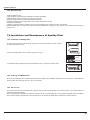
,QVWDOODWLRQ0DQXDO
,QVWDOODWLRQ0DQXDO
1RWLFHVIRU,QVWDOODWLRQ
&DXWLRQ
7KHXQLWVKRXOGEHLQVWDOOHGRQO\E\DXWKRUL]HGVHUYLFHFHQWHUDFFRUGLQJWRORFDORUJRYHUQPHQWUHJXODWLRQVDQGLQFRPSOLDQFHZLWK
WKLVPDQXDO
%HIRUHLQVWDOOLQJSOHDVHFRQWDFWZLWKORFDODXWKRUL]HGPDLQWHQDQFHFHQWHU,IWKHXQLWLVQRWLQVWDOOHGE\WKHDXWKRUL]HGVHUYLFHFHQWHU
WKHPDOIXQFWLRQPD\QRWEHVROYHGGXHWRLQFRYHQLHQWFRQWDFWEHWZHHQWKHXVHUDQGWKHVHUYLFHSHUVRQQHO
:KHQUHPRYLQJWKHXQLWWRWKHRWKHUSODFHSOHDVH¿UVWO\FRQWDFWZLWKWKHORFDODXWKRUL]HGVHUYLFHFHQWHU
:DUQLQJ%HIRUHREWDLQLQJDFFHVVWRWHUPLQDOVDOOVXSSO\FLUFXLWVPXVWEHGLVFRQQHFWHG
)RUDSSOLDQFHVZLWKW\SH<DWWDFKPHQWWKHLQVWUXFWLRQVVKDOOFRQWDLQWKHVXEVWDQFHRIWKHIROORZLQJ,IWKHVXSSO\FRUGLVGDPDJHGLW
PXVWEHUHSODFHGE\WKHPDQXIDFWXUHULWVVHUYLFHDJHQWRUVLPLODUO\TXDOL¿HGSHUVRQVLQRUGHUWRDYRLGDKD]DUG
7KHDSSOLDQFHPXVWEHSRVLWLRQHGVRWKDWWKHSOXJLVDFFHVVLEOH
7KHWHPSHUDWXUHRIUHIULJHUDQWOLQHZLOOEHKLJKSOHDVHNHHSWKHLQWHUFRQQHFWLRQFDEOHDZD\IURPWKHFRSSHUWXEH
7KHLQVWUXFWLRQVVKDOOVWDWHWKHVXEVWDQFHRIWKHIROORZLQJ
7KLVDSSOLDQFHLVQRWLQWHQGHGIRUXVHE\SHUVRQVLQFOXGLQJFKLOGUHQZLWKUHGXFHGSK\VLFDOVHQVRU\RUPHQWDOFDSDELOLWLHVRUODFN
RIH[SHULHQFHDQGNQRZOHGJHXQOHVVWKH\KDYHEHHQJLYHQVXSHUYLVLRQRULQVWUXFWLRQFRQFHUQLQJXVHRIWKHDSSOLDQFHE\DSHUVRQ
UHVSRQVLEOHIRUWKHLUVDIHW\
&KLOGUHQVKRXOGEHVXSHUYLVHGWRHQVXUHWKDWWKH\GRQRWSOD\ZLWKWKHDSSOLDQFH
,QVWDOODWLRQ6LWH,QVWUXFWLRQV
3URSHULQVWDOODWLRQVLWHLVYLWDOIRUFRUUHFWDQGHI¿FLHQWRSHUDWLRQRIWKHXQLW$YRLGWKHIROORZLQJVLWHVZKHUH
ƔVWURQJKHDWVRXUFHVYDSRXUVÀDPPDEOHJDVRUYRODWLOHOLTXLGVDUHHPLWWHG
ƔKLJKIUHTXHQF\HOHFWURPDJQHWLFZDYHVDUHJHQHUDWHGE\UDGLRHTXLSPHQWZHOGHUVDQGPHGLFDOHTXLSPHQW
ƔVDOWODGHQDLUSUHYDLOVVXFKDVFORVHWRFRDVWDODUHDV
ƔWKHDLULVFRQWDPLQDWHGZLWKLQGXVWULDOYDSRXUVDQGRLOV
ƔWKHDLUFRQWDLQVVXOSKXUHVJDVVXFKDVLQKRWVSULQJ]RQHV
ƔFRUURVLRQRUSRRUDLUTXDOLW\H[LVWV
,QVWDOODWLRQ6LWHRI,QGRRU8QLW
7KHDLULQOHWDQGRXWOHWVKRXOGEHDZD\IURPWKHREVWUXFWLRQV(QVXUHWKHDLUFDQEHEORZQWKURXJKWKHZKROHURRP
6HOHFWDVLWHZKHUHWKHFRQGHQVDWHFDQEHHDVLO\GUDLQHGRXWDQGZKHUHLWLVHDVLO\FRQQHFWHGWRRXWGRRUXQLW
6HOHFWDSODFHZKHUHLWLVRXWRIUHDFKRIFKLOGUHQ
6HOHFWDSODFHZKHUHWKHZDOOLVVWURQJHQRXJKWRZLWKVWDQGWKHIXOOZHLJKWDQGYLEUDWLRQRIWKHXQLW
%HVXUHWROHDYHHQRXJKVSDFHWRDOORZDFFHVVIRUURXWLQHPDLQWHQDQFH7KHLQVWDOODWLRQVLWHVKRXOGEHFPRUPRUHDERYHWKH
ÀRRU
6HOHFWDSODFHDERXWPRUPRUHDZD\IURP79VHWRUDQ\RWKHUHOHFWULFDSSOLDQFH
6HOHFWDSODFHZKHUHWKH¿OWHUFDQEHHDVLO\WDNHQRXW
0DNHVXUHWKDWWKHLQGRRUXQLWLVLQVWDOOHGLQDFFRUGDQFHZLWKLQVWDOODWLRQGLPHQVLRQLQVWUXFWLRQV
'RQRWXVHWKHXQLWLQWKHODXQGU\RUE\VZLPPLQJSRROHWF
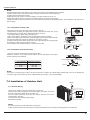
,QVWDOODWLRQ6LWHRI2XWGRRU8QLW
6HOHFWDVLWHZKHUHQRLVHDQGRXWÀRZDLUHPLWWHGE\WKHXQLWZLOOQRWDQQR\QHLJKERUV
6HOHFWDVLWHZKHUHWKHUHLVVXI¿FLHQWYHQWLODWLRQ
6HOHFWDVLWHZKHUHWKHUHLVQRREVWUXFWLRQEORFNLQJWKHLQOHWDQGRXWOHW
7KHVLWHVKRXOGEHDEOHWRZLWKVWDQGWKHIXOOZHLJKWDQGYLEUDWLRQ
6HOHFWDGU\SODFHEXWGRQRWH[SRVHWKHXQLWWRGLUHFWVXQOLJKWRUVWURQJZLQG
0DNHVXUHWKDWWKHRXWGRRUXQLWLVLQVWDOOHGLQDFFRUGDQFHZLWKWKHLQVWDOODWLRQLQVWUXFWLRQVDQGLVFRQYHQLHQWIRUPDLQWHQDQFHDQG
UHSDLU
7KHKHLJKWGLIIHUHQFHEHWZHHQLQGRRUDQGRXWGRRUXQLWVLVZLWKLQPDQGWKHOHQJWKRIWKHFRQQHFWLQJWXELQJGRHVQRWH[FHHG
P
6HOHFWDSODFHZKHUHLWLVRXWRIUHDFKRIFKLOGUHQ
6HOHFWDSODFHZKHUHWKHXQLWGRHVQRWKDYHQHJDWLYHLPSDFWRQSHGHVWULDQVRURQWKHFLW\
,QVWDOODWLRQ0DQXDO
6DIHW\3UHFDXWLRQVIRU(OHFWULF$SSOLDQFHV
$GHGLFDWHGSRZHUVXSSO\FLUFXLWVKRXOGEHXVHGLQDFFRUGDQFHZLWKORFDOHOHFWULFDOVDIHW\UHJXODWLRQV
'RQWGUDJWKHSRZHUFRUGZLWKH[FHVVLYHIRUFH
7KHXQLWVKRXOGEHUHOLDEO\HDUWKHGDQGFRQQHFWHGWRDQH[FOXVLYHHDUWKGHYLFHE\WKHSURIHVVLRQDOV
7KHDLUVZLWFKPXVWKDYHWKHIXQFWLRQVRIPDJQHWLFWULSSLQJDQGKHDWWULSSLQJWRSUHYHQWVKRUWFLUFXLWDQGRYHUORDG
7KHPLQLPXPGLVWDQFHEHWZHHQWKHXQLWDQGFRPEXVWLYHVXUIDFHLVP
7KHDSSOLDQFHVKDOOEHLQVWDOOHGLQDFFRUGDQFHZLWKQDWLRQDOZLULQJUHJXODWLRQV
$QDOOSROHGLVFRQQHFWLRQVZLWFKZLWKDFRQWDFWVHSDUDWLRQRIDWOHDVWPPLQDOOSROHVVKRXOGEHFRQQHFWHGLQ¿[HGZLULQJ
1RWH
Ɣ0DNHVXUHWKHOLYHZLUHQHXWUDOZLUHDQGHDUWKZLUHLQWKHIDPLO\SRZHUVRFNHWDUHSURSHUO\FRQQHFWHG
Ɣ7KHUHVKRXOGEHUHOLDEOHFLUFXLWLQWKHGLDJUDP,QDGHTXDWHRULQFRUUHFWHOHFWULFDOFRQQHFWLRQVPD\FDXVHHOHFWULFVKRFNRU¿UH
(DUWKLQJ5HTXLUHPHQWV
$LUFRQGLWLRQHULVW\SH,HOHFWULFDSSOLDQFH3OHDVHHQVXUHWKDWWKHXQLWLVUHOLDEO\HDUWKHG
7KH\HOORZJUHHQZLUHLQDLUFRQGLWLRQHULVWKHHDUWKLQJZLUHZKLFKFDQQRWEHXVHGIRURWKHUSXUSRVHV,PSURSHUHDUWKLQJPD\
FDXVHHOHFWULFVKRFN
7KHHDUWKUHVLVWDQFHVKRXOGDFFRUGWRWKHQDWLRQDOFULWHULRQ
7KHSRZHUPXVWKDYHUHOLDEOHHDUWKLQJWHUPLQDO3OHDVHGRQRWFRQQHFWWKHHDUWKLQJZLUHZLWKWKHIROORZLQJ
ķ :DWHUSLSHĸ*DVSLSHĹ&RQWDPLQDWLRQSLSHĺ 2WKHUSODFHWKDWSURIHVVLRQDOSHUVRQQHOFRQVLGHULVXQUHOLDEOH
7KHPRGHODQGUDWHGYDOXHVRIIXVHVVKRXOGDFFRUGZLWKWKHVLONSULQWRQIXVHFRYHURUUHODWHG3&%
,QVWDOODWLRQ0DQXDO
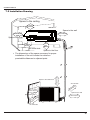
,QVWDOODWLRQ'UDZLQJ
Space to the ceiling
15cm
Above
Space to the wall
15cm Above
15cm Above
Space to the wall
250
cm
Above
300cm
Above
Air outlet side
Space to the floor
The dimensions of the space necessary for proper
installation of the unit include the minimum
permissible distances to adjacent parts.
Space to the obstruction
50cm Above
●
Air inlet side
e
ov
cm
30cm Above
Ab
30
Space to the wall
Space to the wall
50cm Above
20
m
0c
Ab
e
ov
Air outlet side
,QVWDOODWLRQ0DQXDO
,QVWDOO,QGRRU8QLW
,QVWDOODWLRQRI0RXQWLQJ3ODWH
0RXQWLQJSODWHVKRXOGEHLQVWDOOHGKRUL]RQWDOO\$VWKHZDWHUWUD\VRXWOHWIRUWKHLQGRRUXQLWLVWZRZD\W\SHGXULQJLQVWDOODWLRQWKH
LQGRRUXQLWVKRXOGVOLJKWO\VODQWWRZDWHUWUD\VRXWOHWIRUVPRRWKGUDLQDJHRIFRQGHQVDWH
)L[WKHPRXQWLQJSODWHRQWKHZDOOZLWKVFUHZV
%HVXUHWKDWWKHPRXQWLQJSODWHKDVEHHQ¿[HG¿UPO\HQRXJKWRZLWKVWDQGDERXWNJ0HDQZKLOHWKHZHLJKWVKRXOGEHHYHQO\
VKDUHGE\HDFKVFUHZ
.
Wall
Wall
Mark on the middle of it
Gradienter
space to
the wall
150 mm
above
space to
the wall
150 mm
above
Φ70mm
Φ70mm
Left
Right
(Rear piping hole)
(Rear piping hole)
'ULOO3LSLQJ+ROH
Outdoor
Indoor
Wall pipe
Seal pad
6ODQWWKHSLSLQJKROHĭRQWKHZDOOVOLJKWO\GRZQZDUGWRWKHRXWGRRUVLGH
,QVHUWWKHSLSLQJKROHVOHHYHLQWRWKHKROHWRSUHYHQWWKHFRQQHFWLRQSLSLQJDQGZLULQJ
IURPEHLQJGDPDJHGZKHQSDVVLQJWKURXJKWKHKROH
Φ70
,QVWDOODWLRQRI'UDLQ+RVH
&RQQHFW WKH GUDLQ KRVH WR WKH RXWOHW SLSH RI WKH LQGRRU XQLW%LQG WKH MRLQW ZLWK
UXEEHUEHOW
outlet pipe of
indoor unit
rubber belt
3XWWKHGUDLQKRVHLQWRLQVXODWLQJWXEH
outlet pipe of
indoor unit
drain hose
outlet pipe of
indoor unit
:UDS WKH LQVXODWLQJ WXEH ZLWK ZLGH UXEEHU EHOW IURP WKH MRLQW RI RXWOHW SLSH DQG
LQVXODWLQJSLSHVRDVWRSUHYHQWVKLIWRILQVXODWLQJWXEH7KHGUDLQKRVHVKRXOGEH
SODFHGDWDGRZQZDUGVODQWIRUHDV\GLVFKDUJHRIFRQGHQVDWH
drain hose
rubber belt insulating tube
rubber belt
outlet pipe of
indoor unit
insulating tube
connected
1RWH WKH LQVXODWLQJ WXEH VKRXOG EH FRQQHFWHG UHOLDEO\ ZLWK WKH VOHYH RXWVLGH WKH
RXWOHWSLSH7KHGUDLQKRVHVKRXOGEHGRZQZDUGVODQWZLWKRXWGLVWRUWLRQEXOJHRU
ÀXFWXDWLRQ'RQRWSXWWKHZDWHURXWOHWLQWKHZDWHU
bulge
distortion
Flooded
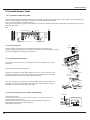
&RQQHFWLQJ,QGRRUDQG2XWGRRU(OHFWULF:LUHV
Wiring Cover
2SHQWKHIURQWSDQHO
5HPRYH WKH ZLULQJ FRYHU&RQQHFW DQG IL[ SRZHU FRQQHFWLRQ FRUG WR WKH
WHUPLQDOERDUGDVVKRZQLQ)LJ
0DNHWKHSRZHUFRQQHFWLRQFRUGWKURXJKWKHKROHLQWKHEDFNRILQGRRUXQLW
5HLQVWDOOWKHFRUGDQFKRUDJHDQGZLULQJFRYHU
5HLQVWDOOWKHIURQWSDQHO
N(1) 2
3
brown
yellowgreen
Outdoor unit connection
Fig.2
,QVWDOODWLRQ0DQXDO
127(
$OOZLUHVEHWZHHQLQGRRUDQGRXWGRRUXQLWVPXVWEHFRQQHFWHGE\WKHTXDOL¿HGHOHFWULFFRQWUDFWRU
Ɣ(OHFWULFZLUHVPXVWEHFRQQHFWHGFRUUHFWO\,PSURSHUFRQQHFWLRQPD\FDXVHPDOIXQFWLRQ
Ɣ7LJKWHQWKHWHUPLQDOVFUHZVVHFXUHO\
Ɣ$IWHUWLJKWHQLQJWKHVFUHZVSXOOWKHZLUHVOLJKWO\WRFRQ¿UPZKHWKHULWV¿UPRUQRW
Ɣ0DNHVXUHWKDWWKHHOHFWULFFRQQHFWLRQVDUHHDUWKHGSURSHUO\WRSUHYHQWHOHFWULFVKRFN
Ɣ0DNHVXUHWKDWDOOZLULQJFRQQHFWLRQVDUHVHFXUHDQGWKHFRYHUSODWHVDUHUHLQVWDOOHGSURSHUO\3RRULQVWDOODWLRQPD\FDXVH¿UHRU
HOHFWULFVKRFN
,QVWDOODWLRQRI,QGRRU8QLW
Gas side piping
Ɣ7KHSLSLQJFDQEHRXWSXWIURPULJKWULJKWUHDUOHIWRUOHIWUHDU
:KHQURXWLQJWKHSLSLQJDQGZLULQJIURPWKHOHIWRUULJKWVLGHRILQGRRUXQLWFXWRII
WKHWDLOLQJVIURPWKHFKDVVLVZKHQQHFHVVDU\$VVKRZQLQ)LJ
&XWRIIWKHWDLOLQJZKHQURXWLQJWKHZLULQJRQO\
&XWRIIWKHWDLOLQJDQGWDLOLQJZKHQURXWLQJERWKWKHZLULQJDQGSLSLQJ
7DNHRXWWKHSLSLQJIURPERG\FDVHZUDSWKHSLSLQJSRZHUFRUGVGUDLQKRVHZLWK
WKHWDSHDQGPDNHWKHPWKURXJKWKHSLSLQJKROH$VVKRZQLQ)LJ
+DQJWKHPRXQWLQJVORWVRIWKHLQGRRUXQLWRQWKHXSSHUKRRNVRIWKHPRXQWLQJSODWH
DQGFKHFNLILWLV¿UPHQRXJK$VVKRZQLQ)LJ
7KHLQVWDOODWLRQVLWHVKRXOGEHFPRUPRUHDERYHWKHÀRRU
External connection
electric wire
Liquid side piping
Tailing 2
side piping
Tailing 1 Gas
insulation
Liquid side
Piping insulation
Finally wrap it
Water drainage pipe
with tape
Fig.3
Left
েৢ
Left rear
Right
Right rear
Fig.4
Fixing hook
Mounting
plate
Mounting
plate
,QVWDOODWLRQRI&RQQHFWLRQ3LSH
Fig.5
$OLJQWKHFHQWHURIWKHSLSHÀDUHZLWKWKHUHOHYDQWYDOYH
6FUHZLQWKHIODUHQXWE\KDQGDQGWKHQ WLJKWHQWKH QXW ZLWKVSDQQHU DQG WRUTXH
ZUHQFKUHIHUULQJWRWKHIROORZLQJ
Indoor unit piping
(N·m)
15̚20
31̚35
50̚55
60̚65
70̚75
Taper nut Piping
Hex nut diameter Tightening torque
Ф6
Ф 9.52
Ф 12
Ф 16
Ф 19
Spanner
Torque
wrench
127(
&RQQHFWWKHFRQQHFWLRQSLSHWRLQGRRUXQLWDW¿UVWDQGWKHQWRRXWGRRUXQLW+DQGOHSLSLQJEHQGLQJZLWKFDUH'RQRWGDPDJHWKH
FRQQHFWLRQSLSH(QVXUHWKDWWKHMRLQWQXWLVWLJKWHQHG¿UPO\RWKHUZLVHLWPD\FDXVHOHDNDJH
,QVWDOODWLRQRI2XWGRRU8QLW
Handle
(OHFWULF:LULQJ
5HPRYHWKHKDQGOHRQWKHULJKWVLGHSODWHRIRXWGRRUXQLW
7DNHRIIZLUHFRUGDQFKRUDJH&RQQHFWDQG¿[SRZHUFRQQHFWLRQFRUGWRWKH
WHUPLQDOERDUG:LULQJVKRXOG¿WWKDWRILQGRRUXQLW
)L[ WKH SRZHU FRQQHFWLRQ FRUG ZLWK ZLUH FODPSV DQG WKHQ FRQQHFW WKH
FRUUHVSRQGLQJFRQQHFWRU
&RQ¿UPLIWKHZLUHKDVEHHQ¿[HGSURSHUO\
5HLQVWDOOWKHKDQGOH
N(1) 2
yellowgreen
3
blue black brown
Indoor unit connection
127(
Ɣ,QFRUUHFWZLULQJPD\FDXVHPDOIXQFWLRQRIVSDUHSDUW
Ɣ$IWHUWKHZLUHKDVEHHQ¿[HGHQVXUHWKHUHLVIUHHVSDFHEHWZHHQWKHFRQQHFWLRQDQG¿[LQJSODFHVRQWKHOHDGZLUH
,QVWDOODWLRQ0DQXDO
$LU3XUJLQJDQG/HDNDJH7HVW
&RQQHFWFKDUJLQJKRVHRIPDQLIROGYDOYHWRFKDUJHHQGRIORZSUHVVXUHYDOYHERWK
KLJKORZSUHVVXUHYDOYHVPXVWEHWLJKWO\VKXW
&RQQHFWMRLQWRIFKDUJLQJKRVHWRYDFXXPSXPS
)XOO\RSHQWKHKDQGOHRI/RPDQLIROGYDOYH
2SHQWKHYDFXXPSXPSIRUYDFXXPL]DWLRQ$WWKHEHJLQQLQJVOLJKWO\ORRVHQMRLQWQXW
RIORZSUHVVXUHYDOYHWRFKHFNLIWKHUHLVDLUFRPLQJLQVLGH,IQRLVHRIYDFXXPSXPS
KDVEHHQFKDQJHGWKHUHDGLQJRIPXOWLPHWHULV7KHQWLJKWHQWKHQXW
.HHSHYDFXDWLQJIRUPRUHWKDQPLQVDQGPDNHVXUHWKHUHDGLQJRIPXOWLPHWHULV
;SDFP+J
)XOO\RSHQKLJKORZSUHVVXUHYDOYHV
5HPRYHFKDUJLQJKRVHIURPFKDUJLQJHQGRIORZSUHVVXUHYDOYH
7LJKWHQERQQHWRIORZSUHVVXUHYDOYH$VVKRZQLQ)LJ
Manifold Valve
Multimeter
-76cmHg
Manometer
Hi handle
Lo Handle
Charging hose
Low pressure valve
Fig.6
Vacuum pump
2XWGRRUFRQGHQVDWH'UDLQDJHRQO\IRUKHDWSXPSW\SH
'XULQJKHDWLQJRSHUDWLRQWKHFRQGHQVDWHDQGGHIURVWLQJZDWHUVKRXOGEHGUDLQHGRXW
UHOLDEO\WKURXJKWKHGUDLQKRVH,QVWDOOWKHRXWGRRUGUDLQFRQQHFWRULQDĭKROHRQWKH
EDVHSODWHDQGDWWDFKWKHGUDLQKRVHWRWKHFRQQHFWRUVRWKDWWKHZDVWHZDWHUIRUPHGLQ
WKHRXWGRRUXQLWFDQEHGUDLQHGRXW7KHKROHGLDPHWHUPXVWEHSOXJJHG
:KHWKHU WR SOXJ RWKHU KROHV ZLOO EH GHWHUPLQHG E\ WKH GHDOHUV DFFRUGLQJ WR DFWXDO
FRQGLWLRQV
&KHFNDIWHU,QVWDOODWLRQDQG7HVW2SHUDWLRQ
&KHFNDIWHU,QVWDOODWLRQ
Items to be checked
Possible malfunction
Has the unit been fixed firmly?
The unit may drop, shake or emit noise.
Have you done the refrigerant leakage test?
It may cause insufficient cooling(heating)
Is thermal insulation sufficient?
It may cause condensation.
Is water drainage satisfactory?
It may cause water leakage.
Is the voltage in accordance with the rated
voltage marked on the nameplate?
Is the electric wiring or piping
connection installed correctly and securely?
It may cause electric malfunction
or damage the unit.
It may cause electric malfunction
or damage the parts.
Has the unit been securely earthed?
It may cause electrical leakage.
Is the power cord specified?
It may cause electric malfunction
or damage the parts.
Is the inlet or outlet blocked?
It may cause insufficient cooling(heating)
Is the length of connection pipes
and refrigerant capacity recorded?
The refrigerant capacity is not accurate.
Drain-water hole
Bottom frame
Drain plug
Drain connecter
Hose (available commercially,
inner dia. 16mm)
,QVWDOODWLRQ0DQXDO
2SHUDWLRQ7HVW
%HIRUH2SHUDWLRQ7HVW
'RQRWVZLWFKRQSRZHUEHIRUHLQVWDOODWLRQLV¿QLVKHGFRPSOHWHO\
(OHFWULFZLULQJPXVWEHFRQQHFWHGFRUUHFWO\DQGVHFXUHO\
&XWRIIYDOYHVRIWKHFRQQHFWLRQSLSHVVKRXOGEHRSHQHG
$OOWKHLPSXULWLHVVXFKDVVFUDSVDQGWKUXPVPXVWEHFOHDUHGIURPWKHXQLW
2SHUDWLRQ7HVW0HWKRG
6ZLWFKRQSRZHUDQGSUHVV212))EXWWRQRQWKHZLUHOHVVUHPRWHFRQWUROOHUWRVWDUWWKHRSHUDWLRQ
3UHVV02'(EXWWRQWRVHOHFWWKH&22/+($71RWDYDLODEOHIRUFRROLQJRQO\XQLW)$1WRFKHFNZKHWKHUWKHRSHUDWLRQLV
QRUPDORUQRW
,QVWDOODWLRQDQG0DLQWHQDQFHRI+HDOWK\)LOWHU
,QVWDOODWLRQRI+HDOWK\)LOWHU
/LIWXSWKHIURQWSDQHOIURPLWVWZRHQGVDVVKRZQE\WKHDUURZGLUHFWLRQDQGWKHQUHPRYH
WKHDLU¿OWHUDVVKRZQ)LJD
$WWDFKWKHKHDOWK\¿OWHURQWRWKHDLU¿OWHUDVVKRZQ)LJE
Fig. a
Fig. b
Air filter
Healthy filter
,QVWDOOWKHDLU¿OWHUSURSHUO\DORQJWKHDUURZGLUHFWLRQLQ)LJFDQGWKHQFORVHWKHSDQHO
Fig. c
&OHDQLQJDQG0DLQWHQDQFH
5HPRYHWKHKHDOWK\¿OWHUDQGUHLQVWDOOLWDIWHUFOHDQLQJDFFRUGLQJWRWKHLQVWDOODWLRQLQVWUXFWLRQ'RQRWXVHEUXVKRUKDUGREMHFWVWR
FOHDQWKH¿OWHU$IWHUFOHDQLQJEHVXUHWRGU\LWLQWKHVKDGH
6HUYLFH/LIH
7KHJHQHUDOVHUYLFHOLIHIRUWKHKHDOWK\¿OWHULVDERXWRQH\HDUXQGHUQRUPDOFRQGLWLRQ$VIRUVLOYHULRQ¿OWHULWLVLQHIIHFWLYHZKHQLWV
VXUIDFHEHFRPHVEODFNJUHHQ
Ɣ7KLVVXSSOHPHQWDU\LQVWUXFWLRQLVSURYLGHGIRUUHIHUHQFHWRWKHXQLWZLWKKHDOWK\¿OWHU,IWKHJUDSKLFVSURYLGHGKHUHLQDUHGLIIHUHQW
IURPWKHDFWXDOSURGXFWSOHDVHUHIHUWRWKHDFWXDOSURGXFW7KHTXDQWLW\RIKHDOWK\¿OWHUVLVEDVHGRQWKHDFWXDOGHOLYHU\
7URXEOHVKRRWLQJ
7URXEOHVKRRWLQJ
3UHFDXWLRQVEHIRUH3HUIRUPLQJ,QVSHFWLRQRU5HSDLU
%H FDXWLRXV GXULQJ LQVWDOODWLRQ DQG PDLQWHQDQFH 'R RSHUDWLRQ IROORZLQJ WKH UHJXODWLRQV WR DYRLG HOHFWULF VKRFN DQG FDVXDOW\ RU HYHQ
GHDWKGXHWRGURSIURPKLJKDWWLWXGH
6WDWLFPDLQWHQDQFHLVWKHPDLQWHQDQFHGXULQJGHHQHUJL]DWLRQRIWKHDLUFRQGLWLRQHU
)RUVWDWLFPDLQWHQDQFHPDNHVXUHWKDWWKHXQLWLVGHHQHUJL]HGDQGWKHSOXJLVGLVFRQQHFWHG
G\QDPLFPDLQWHQDQFHLVWKHPDLQWHQDQFHGXULQJHQHUJL]DWLRQRIWKHXQLW
%HIRUHG\QDPLFPDLQWHQDQFHFKHFNWKHHOHFWULFLW\DQGHQVXUHWKDWWKHUHLVJURXQGZLUHRQWKHVLWH&KHFNLIWKHUHLVHOHFWULFLW\RQWKH
KRXVLQJDQGFRQQHFWLRQFRSSHUSLSHRIWKHDLUFRQGLWLRQHUZLWKYROWDJHWHVWHU$IWHUHQVXUHLQVXODWLRQSODFHDQGWKHVDIHW\WKHPDLQWH
QDQFHFDQEHSHUIRUPHG
7DNHVXI¿FLHQWFDUHWRDYRLGGLUHFWO\WRXFKLQJDQ\RIWKHFLUFXLWSDUWVZLWKRXW¿UVWWXUQLQJRIIWKHSRZHU
$WWLPHVVXFKDVZKHQWKHFLUFXLWERDUGLVWREHUHSODFHGSODFHWKHFLUFXLWERDUGDVVHPEO\LQDYHUWLFDOSRVLWLRQ
1RUPDOO\GLDJQRVHWURXEOHVDFFRUGLQJWRWKHWURXEOHGLDJQRVLVSURFHGXUHDVGHVFULEHGEHORZ5HIHUWRWKHFKHFNSRLQWVLQVHUYLFLQJZULW
WHQRQWKHZLULQJGLDJUDPVDWWDFKHGWRWKHLQGRRURXWGRRUXQLWV
1R 7URXEOHVKRRWLQJSURFHGXUH
&RQ¿UPDWLRQ
-XGJHPHQWE\)ODVKLQJ/('RI,QGRRU2XWGRRU8QLW
+RZWR&KHFN6LPSO\WKH0DLQ3DUW
127(
$ ODUJHFDSDFLW\ HOHFWURO\WLF FDSDFLWRU LV XVHG LQ WKH RXWGRRU XQLW FRQWUROOHULQYHUWHU7KHUHIRUHLI WKH SRZHU
VXSSO\LVWXUQHGRIIFKDUJHFKDUJLQJYROWDJH'&9WR9UHPDLQVDQGGLVFKDUJLQJWDNHVDORWRIWLPH$IWHU
WXUQLQJ RII WKH SRZHU VRXUFHLI WRXFKLQJ WKH FKDUJLQJ VHFWLRQ EHIRUH GLVFKDUJLQJ DQ HOHFWULFDO VKRFN PD\ EH
FDXVHG'LVFKDUJHWKHHOHFWURO\WLFFDSDFLWRUFRPSOHWHO\E\XVLQJVROGHULQJLURQHWF
'LVFKDUJLQJPHWKRG!
UHPRYHWKHLQYHUWHUFRYHU2XWGRRU8QLW
$VVKRZQEHORZFRQQHFWWKHGLVFKDUJHUHVLVWDQFHDSSUR[ȍ:RUSOXJRIWKHVROGHULQJLURQWRYROWDJHEHWZHHQWHUPLQDOV
RIWKHHOHFWURO\WLFFDSDFLWRUWHVW³'´DQG³(´SRLQWRQ3&%RDUGIRUVDQGWKHQSHUIRUPGLVFKDUJLQJ
7URXEOHVKRRWLQJ
discharge resistance or
plug of soldering iron
&RQÀUPDWLRQ
&RQ¿UPDWLRQRI3RZHU6XSSO\
&RQ¿UPWKDWWKHSRZHUEUHDNHURSHUDWHV21QRUPDOO\
&RQ¿UPDWLRQRI3RZHU9ROWDJH
&RQ¿UPWKDWSRZHUYROWDJHLV$&
,ISRZHUYROWDJHLVQRWLQWKLVUDQJHWKHXQLWPD\QRWRSHUDWHQRUPDOO\
-XGJHPHQWE\)ODVKLQJ/('RI,QGRRU2XWGRRU8QLW
7URXEOHVKRRWLQJ
'LVSOD\0HWKRGRI,QGRRU8QLW
12
+LJK
SUHVVXUH
SURWHFWLRQRI
V\VWHP
(
ƶ
ƿ
ƿ
ƿ
$QWLIUHH]LQJ
SURWHFWLRQ
(
2))6
DQGEOLQN
WZLFH
Ƶ
ƶ
Ƶ
ƶ
+LJK
GLVFKDUJH
WHPSHUDWXUH
SURWHFWLRQRI
FRPSUHVVRU
(
2))6
DQGEOLQN
WLPHV
Ƶ
ƶ
Ƶ
ƿ
2YHUFXUUHQW
SURWHFWLRQ
(
2))6
DQGEOLQN
WLPHV
ƶ
Ƶ
ƿ
ƶ
&RPPXQL
FDWLRQ
0DOIXQFWLRQ
(
2))6
DQGEOLQN
WLPHV
ƶ
ƶ
ƶ
ƿ
(
2))6
DQGEOLQN
WLPHV
Ƶ
ƶ
Ƶ
Ƶ
3*PRWRU
LQGRRUIDQ
PRWRUGRHV
QRWRSHUDWH
+
2))6
DQGEOLQN
WLPHV
0DOIXQFWLRQ
SURWHFWLRQRI
MXPSHUFDS
&
2))6
DQGEOLQN
WLPHV
,QGRRU
DPELHQW
WHPSHUDWXUH
VHQVRULV
RSHQVKRUW
FLUFXLWHG
)
+LJK
WHPSHUDWXUH
UHVLVWDQW
SURWHFWLRQ
$&VWDWXV
3RVVLEOH&DXVHV
,QGLFDWRU'LVSOD\GXULQJ
'XDO EOLQNLQJ21VDQG2))V Ŷ,OOXPLQDWHGƿ %OLQN
&RGH
2SHUDWLRQ &RRO
+HDWLQJ
'
' ' '
'LVSOD\
,QGLFDWRU ,QGLFDWRU ,QGLFDWRU ' ' ' '
2))V
DQGEOLQN
RQFH
RIGLVSOD\VWDWXVDQG
WKH\ZLOOEHGLVSOD\HG
FLUFXODUO\HYHU\V
Ƒ2))
0DOIXQFWLRQ
1DPH
'LVSOD\0HWKRGRI
2XWGRRU8QLW
,QGLFDWRUKDVNLQGV
2))6
DQGEOLQN
RQFH
'XULQJFRROLQJDQGGU\LQJ
3RVVLEOHUHDVRQV
RSHUDWLRQH[FHSWLQGRRU
5HIULJHUDQWZDVVXSHUDEXQGDQW
IDQRSHUDWHVDOOORDGVVWRS
3RRUKHDWH[FKDQJHLQFOXGLQJ
RSHUDWLRQ
¿OWKEORFNDJHRIKHDWH[FKDQJHU
'XULQJKHDWLQJRSHUDWLRQWKH DQGEDGUDGLDWLQJHQYLURQPHQW
FRPSOHWHXQLWVWRSV
$PELHQWWHPSHUDWXUHLVWRRKLJK
'XULQJFRROLQJDQGGU\LQJ
3RRUDLUUHWXUQLQLQGRRUXQLW
RSHUDWLRQFRPSUHVVRUDQG
)DQVSHHGLVDEQRUPDO
RXWGRRUIDQVWRSZKLOHLQGRRU (YDSRUDWRULVGLUW\
IDQRSHUDWHV
'XULQJFRROLQJDQGGU\LQJ
3OHDVHUHIHUWRWKHPDOIXQFWLRQ
RSHUDWLRQFRPSUHVVRUDQG
DQDO\VLVGLVFKDUJHSURWHFWLRQ
RXWGRRUIDQVWRSZKLOHLQGRRU RYHUORDG
IDQRSHUDWHV'XULQJKHDWLQJ
RSHUDWLRQDOOORDGVVWRS
'XULQJFRROLQJDQGGU\LQJ
6XSSO\YROWDJHLVXQVWDEOH
RSHUDWLRQFRPSUHVVRUDQG
6XSSO\YROWDJHLVWRRORZDQG
RXWGRRUIDQVWRSZKLOHLQGRRU ORDGLVWRRKLJK
IDQRSHUDWHV'XULQJKHDWLQJ
(YDSRUDWRULVGLUW\
RSHUDWLRQDOOORDGVVWRS
'XULQJFRROLQJRSHUDWLRQ
5HIHUWRWKHFRUUHVSRQGLQJ
FRPSUHVVRUVWRSVZKLOHLQGRRU PDOIXQFWLRQDQDO\VLV
IDQPRWRURSHUDWHV'XULQJ
KHDWLQJRSHUDWLRQWKHFRPSOHWH
XQLWVWRSV
'XULQJFRROLQJRSHUDWLRQ
5HIHUWRWKHPDOIXQFWLRQDQDO\VLV
FRPSUHVVRUZLOOVWRSZKLOH
RYHUORDGKLJKWHPSHUDWXUH
LQGRRUIDQZLOORSHUDWH'XULQJ UHVLVWDQW
KHDWLQJRSHUDWLRQWKHFRPSOHWH
XQLWVWRSV
, Q G R R U I D Q R X W G R R U I D Q 7KHIHHGEDFNWHUPLQDORI3*
FRPSUHVVRU DQG HOHFWULF KHDW PRWRULVQRWFRQQHFWHGWLJKWO\
WXEH VWRS RSHUDWLRQ +RUL]RQWDO 7KHFRQWUROWHUPLQDORI3*PRWRU
O R X Y H U V W R S V D W W K H F X U U H Q W LVQRWFRQQHFWHGWLJKWO\)DQEODGH
SRVLWLRQ
URWDWHVXQVPRRWKO\
0DOIXQFWLRQRIPRWRU
&RQWUROOHULVGDPDJHG
2SHUDWLRQRIUHPRWHFRQWUROOHU 7KHUH
VQRWMXPSHUFDSRQWKH
RUFRQWUROSDQHOLVDYDLODEOHEXW FRQWUROOHU
WKHXQLWZRQ
WDFW
-XPSHUFDSLVQRWLQVHUWHG
SURSHUO\DQGWLJKWO\
-XPSHUFDSLVGDPDJHG
&RQWUROOHULVGDPDJHG
'XULQJFRROLQJDQGGU\LQJ
7KHZLULQJWHUPLQDOEHWZHHQ
RSHUDWLRQLQGRRUXQLWRSHUDWHV LQGRRUDPELHQWWHPSHUDWXUHVHQVRU
ZKLOHRWKHUORDGVZLOOVWRS
DQGFRQWUROOHULVORRVHQHGRUSRRUO\
GXULQJKHDWLQJRSHUDWLRQ
FRQWDFWHG
WKHFRPSOHWHXQLWZLOOVWRS
7KHUH
VVKRUWFLUFXLWGXHWRWULS
RSHUDWLRQ
RYHURIWKHSDUWVRQFRQWUROOHU
,QGRRUDPELHQWWHPSHUDWXUHVHQVRU
LVGDPDJHG3OHDVHFKHFNLWE\
UHIHUULQJWRWKHUHVLVWDQFHWDEOHIRU
WHPSHUDWXUHVHQVRU0DLQERDUG
LVEURNHQ
7URXEOHVKRRWLQJ
12
0DOIXQFWLRQ
1DPH
,QGRRU
HYDSRUDWRU
WHPSHUDWXUH
VHQVRULV
RSHQVKRUW
FLUFXLWHG
2XWGRRU
DPELHQW
WHPSHUDWXUH
VHQVRULV
RSHQVKRUW
FLUFXLWHG
2XWGRRU
FRQGHQVHU
WHPSHUDWXUH
VHQVRULV
RSHQVKRUW
FLUFXLWHG
2XWGRRU
GLVFKDUJH
WHPSHUDWXUH
VHQVRULV
RSHQVKRUW
FLUFXLWHG
/LPLW
GHFUHDVH
IUHTXHQF\
GXHWR
RYHUORDG
'HFUHDVH
IUHTXHQF\
GXHWR
RYHUFXUUHQW
'HFUHDVH
IUHTXHQF\
GXHWR
KLJKDLU
GLVFKDUJH
'LVSOD\0HWKRGRI
2XWGRRU8QLW
,QGLFDWRUKDVNLQGV
'LVSOD\0HWKRGRI,QGRRU8QLW
RIGLVSOD\VWDWXVDQG
WKH\ZLOOEHGLVSOD\HG
FLUFXODUO\HYHU\V
Ƒ2))
,QGLFDWRU'LVSOD\GXULQJ
'XDO EOLQNLQJ21VDQG2))V Ŷ,OOXPLQDWHGƿ %OLQN
&RGH
'
'
' '
+HDWLQJ
'LVSOD\ 2SHUDWLRQ &RRO
' ' ' '
,QGLFDWRU ,QGLFDWRU ,QGLFDWRU
2))6
DQG
EOLQN
WZLFH
)
)
)
)
)
)
)
2))6
DQG
EOLQN
WLPHV
2))6
DQG
EOLQN
WLPHV
2))6
DQG
EOLQN
WLPHV
2))6
DQG
EOLQN
IRU
WLPHV
2))6
DQG
EOLQN
WLPHV
2))6
DQG
EOLQN
WLPHV
ƶ
ƶ
ƶ
ƶ
ƶ
ƶ
ƿ
ƿ
ƿ
9ROWDJHIRU
'&EXVEDU
LVWRRKLJK
0DOIXQFWLRQ
RIFRPSOHWH
XQLWVFXUUHQW
GHWHFWLRQ
2YHUFXUUHQW
SURWHFWLRQRI
SKDVH
FXUUHQWIRU
FRPSUHVVRU
3+
8
2))6
DQG
EOLQN
WLPHV
3
2))6
DQG
EOLQN
WLPHV
ƶ
3RVVLEOH&DXVHV
7KHXQLWZLOOVWRSRSHUDWLRQ
7KHZLULQJWHUPLQDOEHWZHHQ
DVLWUHDFKHVWKHWHPSHUDWXUH LQGRRUHYDSRUDWRUWHPSHUDWXUH
SRLQW'XULQJFRROLQJDQGGU\LQJ VHQVRUDQGFRQWUROOHULVORRVHQHG
RSHUDWLRQH[FHSWLQGRRUIDQ
RUSRRUO\FRQWDFWHG
RSHUDWHVRWKHUORDGVVWRS
7KHUH
VVKRUWFLUFXLWGXHWRWKH
RSHUDWLRQ'XULQJKHDWLQJ
WULSRYHURIWKHSDUWVRQFRQWUROOHU
RSHUDWLRQWKHFRPSOHWHXQLW
,QGRRUHYDSRUDWRUWHPSHUDWXUH
VWRSVRSHUDWLRQ
VHQVRULVGDPDJHG3OHDVHFKHFN
LWE\UHIHUULQJWRWKHUHVLVWDQFH
WDEOHIRUWHPSHUDWXUHVHQVRU
0DLQERDUGLVEURNHQ
'XULQJFRROLQJDQGGU\LQJ
2XWGRRUWHPSHUDWXUHVHQVRU
RSHUDWLQJFRPSUHVVRUVWRSV
KDVQWEHHQFRQQHFWHGZHOORU
ZKLOHLQGRRUIDQRSHUDWHV
LVGDPDJHG3OHDVHFKHFNLWE\
'XULQJKHDWLQJRSHUDWLRQWKH UHIHUULQJWRWKHUHVLVWDQFHWDEOHIRU
FRPSOHWHXQLWZLOOVWRSRSHUDWLRQ WHPSHUDWXUHVHQVRU
'XULQJFRROLQJDQGGU\LQJ
RSHUDWLRQFRPSUHVVRUVWRSV
ZKLOHLQGRRUIDQZLOORSHUDWH
'XULQJKHDWLQJRSHUDWLRQ
WKHFRPSOHWHXQLWZLOOVWRS
RSHUDWLRQ
'XULQJFRROLQJDQGGU\LQJ
RSHUDWLRQFRPSUHVVRUZLOOVRS
DIWHURSHUDWLQJIRUDERXWPLQV
ZKLOHLQGRRUIDQZLOORSHUDWH
ƿ 'XULQJKHDWLQJRSHUDWLRQWKH
FRPSOHWHXQLWZLOOVWRSDIWHU
RSHUDWLQJIRUDERXWPLQV
2XWGRRUWHPSHUDWXUHVHQVRU
KDVQWEHHQFRQQHFWHGZHOORU
LVGDPDJHG3OHDVHFKHFNLWE\
UHIHUULQJWRWKHUHVLVWDQFHWDEOHIRU
WHPSHUDWXUHVHQVRU
2XWGRRUWHPSHUDWXUHVHQVRU
KDVQWEHHQFRQQHFWHGZHOORULV
GDPDJHG3OHDVHFKHFNLWE\
UHIHUULQJWRWKHUHVLVWDQFHWDEOHIRU
WHPSHUDWXUHVHQVRU
7KHKHDGRIWHPSHUDWXUHVHQVRU
KDVQWEHHQLQVHUWHGLQWRWKH
FRSSHUWXEH
Ƶ
ƶ
ƿ
$OOORDGVRSHUDWHQRUPDOO\ZKLOH 5HIHUWRWKHPDOIXQFWLRQDQDO\VLV
RSHUDWLRQIUHTXHQF\IRU
RYHUORDGKLJKWHPSHUDWXUH
UHVLVWDQW
ƿ FRPSUHVVRULVGHFUHDVHG
Ƶ
Ƶ
ƶ
Ƶ FRPSUHVVRULVGHFUHDVHG
Ƶ
Ƶ
ƶ
2))6
DQG
EOLQN
WLPHV
Ƶ
$&VWDWXV
ƶ
Ƶ
ƶ
ƶ
Ƶ
ƿ
ƶ
ƿ
ƶ
$OOORDGVRSHUDWHQRUPDOO\ZKLOH 7KH LQSXW VXSSO\ YROWDJH LV WRR
RSHUDWLRQIUHTXHQF\IRU
ORZ
6\VWHP SUHVVXUH LV WRR KLJK DQG
RYHUORDG
$OOORDGVRSHUDWHQRUPDOO\ZKLOH 2YHUORDG RU WHPSHUDWXUH LV WRR
RSHUDWLRQIUHTXHQF\IRU
KLJK
5HIULJHUDQWLVLQVXI¿FLHQW
ƶ FRPSUHVVRULVGHFUHDVHG
0DOIXQFWLRQ RI HOHFWULF H[SDQVLRQ
YDOYH(.9
'XULQJFRROLQJDQGGU\LQJ
RSHUDWLRQFRPSUHVVRUZLOOVWRS
ZKLOHLQGRRUIDQZLOORSHUDWH
'XULQJKHDWLQJRSHUDWLRQWKH
FRPSOHWHXQLWZLOOVWRS
RSHUDWLRQ
0HDVXUHWKHYROWDJHRISRVLWLRQ
/ DQG 1 RQ ZLULQJ ERDUG ;7 LI
WKHYROWDJHLVKLJKHUWKDQ9$&
WXUQ RQ WKH XQLW DIWHU WKH VXSSO\
YROWDJHLVLQFUHDVHGWRWKHQRUPDO
UDQJH
ƿ
, I W K H $ & L Q S X W L V Q R U P D O PHDVXUHWKHYROWDJHRIHOHFWURO\WLF
FDSDFLWRU&RQFRQWUROSDQHO$3
LI LWV QRUPDO WKHUHV PDOIXQFWLRQ
IRU WKH FLUFXLW SOHDVH UHSODFH WKH
FRQWUROSDQHO$3
'XULQJFRROLQJDQGGU\LQJ
7KHUHV FLUFXLW PDOIXQFWLRQ RQ
RSHUDWLRQWKHFRPSUHVVRUZLOO RXWGRRU XQLWV FRQWURO SDQHO$3
VWRSZKLOHLQGRRUIDQZLOORSHUDWH SOHDVH UHSODFH WKH RXWGRRU XQLWV
Ƶ 'XULQJKHDWLQJRSHUDWLQJ
FRQWUROSDQHO$3
WKHFRPSOHWHXQLWZLOOVWRS
RSHUDWLRQ
'XULQJFRROLQJDQGGU\LQJ
RSHUDWLRQFRPSUHVVRUZLOOVWRS
ZKLOHLQGRRUIDQZLOORSHUDWH
ƶ 'XULQJKHDWLQJRSHUDWLRQWKH
FRPSOHWHXQLWZLOOVWRS
RSHUDWLRQ
5HIHUWRWKHPDOIXQFWLRQ
DQDO\VLV,30SURWHFWLRQORVV
RIV\QFKURQLVPSURWHFWLRQDQG
RYHUFXUUHQWSURWHFWLRQRISKDVH
FXUUHQWIRUFRPSUHVVRU
7URXEOHVKRRWLQJ
'LVSOD\0HWKRGRI,QGRRU8QLW
12
0DOIXQFWLRQ
1DPH
'LVSOD\0HWKRGRI
2XWGRRU8QLW
,QGLFDWRUKDVNLQGV
RIGLVSOD\VWDWXVDQG
WKH\ZLOOEHGLVSOD\HG
FLUFXODUO\HYHU\V
$&VWDWXV
3RVVLEOH&DXVHV
Ƒ2))
,QGLFDWRU'LVSOD\GXULQJ
'XDO EOLQNLQJ21VDQG2))V Ŷ,OOXPLQDWHGƿ %OLQN
&RGH
'
'
' '
+HDWLQJ
'LVSOD\ 2SHUDWLRQ &RRO
,QGLFDWRU ,QGLFDWRU ,QGLFDWRU ' ' ' '
'HIURVWLQJ
6WDWLF
GHGXVWLQJ
SURWHFWLRQ
2YHUORDG
SURWHFWLRQIRU
FRPSUHVVRU
6\VWHPLV
DEQRUPDO
,30
SURWHFWLRQ
3)&
SURWHFWLRQ
'HV\QFKURQ
L]LQJRI
FRPSUHVVRU
'HFUHDVH
IUHTXHQF\
GXHWRKLJK
WHPSHUDWXUH
UHVLVWDQW
GXULQJ
KHDWLQJ
RSHUDWLRQ
)DLOXUHVWDUW
XS
0DOIXQFWLRQ
RISKDVH
FXUUHQW
GHWHFWLRQ
FLUFXLWIRU
FRPSUHVVRU
+
+
+
+
+
+&
+
2))6
DQGEOLQN
RQFH
'HIURVWLQJZLOORFFXULQKHDWLQJ ,WVWKHQRUPDOVWDWH
PRGH&RPSUHVVRUZLOORSHUDWH
ZKLOHLQGRRUIDQZLOOVWRS
RSHUDWLRQ
2))6
DQGEOLQN
WZLFH
2))6
DQGEOLQN
WLPHV
2))6
DQGEOLQN
WLPHV
2))6
DQGEOLQN
WLPHV
2))6
DQGEOLQN
WLPHV
2))6
DQGEOLQN
WLPHV
ƶ
Ƶ
ƶ
ƶ
ƶ
ƿ
ƶ
ƿ
Ƶ
ƿ
ƿ
'XULQJFRROLQJDQGGU\LQJ
RSHUDWLRQFRPSUHVVRUZLOOVWRS
ZKLOHLQGRRUIDQZLOORSHUDWH
ƶ 'XULQJKHDWLQJRSHUDWLRQWKH
FRPSOHWHXQLWZLOOVWRS
RSHUDWLRQ
Ƶ
'XULQJFRROLQJDQGGU\LQJ
5HIHUWRWKHPDOIXQFWLRQDQDO\VLV
RSHUDWLRQFRPSUHVVRUZLOOVWRS RYHUORDGKLJKWHPSHUDWXUH
ZKLOHLQGRRUIDQZLOORSHUDWH
UHVLVWDQW
Ƶ 'XULQJKHDWLQJRSHUDWLRQWKH
FRPSOHWHXQLWZLOOVWRS
RSHUDWLRQ
ƶ
ƿ
Ƶ
2))6
DQGEOLQN
WLPHV
Ƶ
+
/&
2))6
DQGEOLQN
WLPHV
ƶ
ƶ
ƿ
ƶ
ƿ
5HIHUWRWKHPDOIXQFWLRQ
DQDO\VLV,30SURWHFWLRQORVV
RIV\QFKURQLVPSURWHFWLRQDQG
RYHUFXUUHQWSURWHFWLRQRISKDVH
FXUUHQWIRUFRPSUHVVRU
5HIHUWRWKHPDOIXQFWLRQDQDO\VLV
5HIHUWRWKHPDOIXQFWLRQ
DQDO\VLV,30SURWHFWLRQORVV
RIV\QFKURQLVPSURWHFWLRQDQG
RYHUFXUUHQWSURWHFWLRQRISKDVH
FXUUHQWIRUFRPSUHVVRU
5HIHUWRWKHPDOIXQFWLRQDQDO\VLV
RYHUORDGKLJKWHPSHUDWXUH
UHVLVWDQW
ƿ
ƿ
ƶ
'XULQJFRROLQJDQGGU\LQJ
5HIHUWRWKHPDOIXQFWLRQDQDO\VLV
RSHUDWLRQFRPSUHVVRUZLOOVWRS
ZKLOHLQGRRUIDQZLOORSHUDWH
ƿ 'XULQJKHDWLQJRSHUDWLRQWKH
FRPSOHWHXQLWZLOOVWRS
RSHUDWLRQ
2))6
DQGEOLQN
WLPHV
8
'XULQJFRROLQJDQGGU\LQJ
RSHUDWLRQFRPSUHVVRUZLOOVWRS
Ƶ ZKLOHLQGRRUIDQZLOORSHUDWH
'XULQJKHDWLQJRSHUDWLRQWKH
FRPSOHWHXQLWZLOOVWRS
RSHUDWLRQ
'XULQJFRROLQJDQGGU\LQJ
RSHUDWLRQFRPSUHVVRUZLOOVWRS
ƿ ZKLOHLQGRRUIDQZLOORSHUDWH
'XULQJKHDWLQJRSHUDWLRQWKH
FRPSOHWHXQLWZLOOVWRS
RSHUDWLRQ
'XULQJFRROLQJDQGGU\LQJ
RSHUDWLRQFRPSUHVVRUZLOOVWRS
ƿ ZKLOHLQGRRUIDQZLOORSHUDWH
'XULQJKHDWLQJRSHUDWLRQWKH
FRPSOHWHXQLWZLOOVWRS
RSHUDWLRQ
$OOORDGVRSHUDWHQRUPDOO\ZKLOH
RSHUDWLRQIUHTXHQF\IRU
FRPSUHVVRULVGHFUHDVHG
:LULQJ WHUPLQDO 29&&203
LV ORRVHQHG ,Q QRUPDO VWDWH WKH
UHVLVWDQFHIRUWKLVWHUPLQDOVKRXOG
EHOHVVWKDQRKP
5HIHUWRWKHPDOIXQFWLRQDQDO\VLV
GLVFKDUJHSURWHFWLRQRYHUORDG
Ƶ
'XULQJFRROLQJDQGGU\LQJ
5HSODFHRXWGRRUFRQWUROSDQHO$3
RSHUDWLRQFRPSUHVVRUZLOOVWRS
ZKLOHLQGRRUIDQZLOORSHUDWH
'XULQJKHDWLQJRSHUDWLRQWKH
ƶ FRPSOHWHXQLWZLOOVWRS
7URXEOHVKRRWLQJ
12
0DOIXQFWLRQ
1DPH
((3520
PDOIXQFWLRQ
&KDUJLQJ
PDOIXQFWLRQ
RIFDSDFLWRU
0DOIXQFWLRQ
RIPRGXOH
WHPSHUDWXUH
VHQVRUFLUFXLW
0RGXOHKLJK
WHPSHUDWXUH
SURWHFWLRQ
0DOIXQFWLRQ
RIYROWDJH
GURSSLQJIRU
'&EXVEDU
'LVSOD\0HWKRGRI
2XWGRRU8QLW
,QGLFDWRUKDVNLQGV
'LVSOD\0HWKRGRI,QGRRU8QLW
RIGLVSOD\VWDWXVDQG
WKH\ZLOOEHGLVSOD\HG
FLUFXODUO\HYHU\V
,QGLFDWRU'LVSOD\GXULQJEOLQNLQJ Ƒ2))
Ŷ,OOXPLQDWHGƿ %OLQN
'XDO 21VDQG2))V
&RGH
'
'
' '
+HDWLQJ
'LVSOD\ 2SHUDWLRQ &RRO
,QGLFDWRU ,QGLFDWRU ,QGLFDWRU ' ' ' '
((
2))6
DQGEOLQN
WLPHV
38
2))6
DQGEOLQN
WLPHV
3
2))6
DQGEOLQN
WLPHV
ƶ
ƶ
ƶ
ƶ
Ƶ
ƶ
8
2))6
DQGEOLQN
WLPHV
ƶ
ƶ
'XULQJFRROLQJDQGGU\LQJ
5HIHUWRWKHSDUWWKUHH²FKDUJLQJ
RSHUDWLRQFRPSUHVVRUZLOOVWRS PDOIXQFWLRQDQDO\VLVRIFDSDFLWRU
Ƶ ZKLOHLQGRRUIDQZLOORSHUDWH
'XULQJKHDWLQJRSHUDWLRQWKH
FRPSOHWHXQLWZLOOVWRS
Ƶ
Ƶ
ƶ
ƿ
ƶ
Ƶ
Ƶ
2))6
DQGEOLQN
WLPHV
'XULQJFRROLQJDQGGU\LQJ
5HSODFHRXWGRRUFRQWUROSDQHO
RSHUDWLRQFRPSUHVVRUZLOOVWRS $3
ZKLOHLQGRRUIDQZLOORSHUDWH
ƿ 'XULQJKHDWLQJRSHUDWLRQWKH
FRPSOHWHXQLWZLOOVWRS
'XULQJFRROLQJRSHUDWLRQ
$IWHUWKHFRPSOHWHXQLWLVGH
FRPSUHVVRUZLOOVWRSZKLOH
HQHUJL]HGIRUPLQVFKHFN
LQGRRUIDQZLOORSHUDWH'XULQJ ZKHWKHUWKHWKHUPDOJUHDVHRQ
,300RGXOHRIRXWGRRUFRQWURO
Ƶ KHDWLQJRSHUDWLRQWKHFRPSOHWH
XQLWZLOOVWRS
SDQHO$3LVVXI¿FLHQWDQG
ZKHWKHUWKHUDGLDWRULVLQVHUWHG
WLJKWO\,ILWVQRXVHSOHDVHUHSODFH
FRQWUROSDQHO$3
'XULQJFRROLQJDQGGU\LQJ
6XSSO\YROWDJHLVXQVWDEOH
RSHUDWLRQFRPSUHVVRUZLOOVWRS
Ƶ ZKLOHLQGRRUIDQZLOORSHUDWH
'XULQJKHDWLQJRSHUDWLRQWKH
FRPSOHWHXQLWZLOOVWRS
'XULQJFRROLQJDQGGU\LQJ
RSHUDWLRQFRPSUHVVRUZLOOVWRS
ZKLOHLQGRRUIDQZLOORSHUDWH
'XULQJKHDWLQJRSHUDWLRQWKH
FRPSOHWHXQLWZLOOVWRS
9ROWDJHRI
'&EXVEDU
LVWRRORZ
3/
ƶ
Ƶ
Ƶ
/LPLW
GHFUHDVH
IUHTXHQF\
GXHWRKLJK
WHPSHUDWXUH
RIPRGXOH
(8
Ƶ
Ƶ
Ƶ
7KHIRXUZD\
YDOYHLV
DEQRUPDO
8
Ƶ
ƶ
ƿ
=HUR
FURVVLQJ
PDOIXQFWLRQ
RIRXWGRRU
XQLW
8
Ƶ
Ƶ
ƿ
/LPLW
GHFUHDVH
IUHTXHQF\
GXHWR
DQWLIUHH]LQJ
)+
3RVVLEOH&DXVHV
'XULQJFRROLQJDQGGU\LQJ
5HSODFHRXWGRRUFRQWUROSDQHO
RSHUDWLRQFRPSUHVVRUZLOOVWRS $3
Ƶ ZKLOHLQGRRUIDQZLOORSHUDWH
'XULQJKHDWLQJRSHUDWLRQWKH
FRPSOHWHXQLWZLOOVWRS
2))6
DQGEOLQN
WLPHV
3
$&VWDWXV
Ƶ
Ƶ
Ƶ
0HDVXUHWKHYROWDJHRISRVLWLRQ
/DQG1RQZLULQJERDUG;7LI
WKHYROWDJHLVKLJKHUWKDQ9$&
WXUQRQWKHXQLWDIWHUWKHVXSSO\
YROWDJHLVLQFUHDVHGWRWKHQRUPDO
UDQJH
ƶ
,IWKH$&LQSXWLVQRUPDO
PHDVXUHWKHYROWDJHRIHOHFWURO\WLF
FDSDFLWRU&RQFRQWUROSDQHO$3
LILWVQRUPDOWKHUHVPDOIXQFWLRQ
IRUWKHFLUFXLWSOHDVHUHSODFHWKH
FRQWUROSDQHO$3
$OOORDGVRSHUDWHQRUPDOO\ZKLOH 'LVFKDUJLQJDIWHUWKHFRPSOHWH
XQLWLVGHHQHUJL]HGIRUPLQV
RSHUDWLRQIUHTXHQF\IRU
FRPSUHVVRULVGHFUHDVHG
FKHFNZKHWKHUWKHWKHUPDOJUHDVH
RQ
,300RGXOHRIRXWGRRUFRQWURO
ƿ
SDQHO$3LVVXI¿FLHQWDQG
ZKHWKHUWKHUDGLDWRULVLQVHUWHG
WLJKWO\
,ILWVQRXVHSOHDVHUHSODFHFRQWURO
SDQHO$3
,IWKLVPDOIXQFWLRQRFFXUVGXULQJ 6XSSO\YROWDJHLVORZHUWKDQ
KHDWLQJRSHUDWLRQWKHFRPSOHWH $&9
:LULQJWHUPLQDO9LVORRVHQHG
ƶ XQLWZLOOVWRSRSHUDWLRQ
RUEURNHQ
9LVGDPDJHGSOHDVHUHSODFH
9
'XULQJFRROLQJRSHUDWLRQ
5HSODFHRXWGRRUFRQWUROSDQHO
FRPSUHVVRUZLOOVWRSZKLOH
$3
LQGRRUIDQZLOORSHUDWHGXULQJ
ƶ KHDWLQJWKHFRPSOHWHXQLWZLOO
VWRSRSHUDWLRQ
ƶ
$OOORDGVRSHUDWHQRUPDOO\ZKLOH 3RRUDLUUHWXUQLQLQGRRUXQLWRUIDQ
RSHUDWLRQIUHTXHQF\IRU
VSHHGLVWRRORZ
FRPSUHVVRULVGHFUHDVHG
7URXEOHVKRRWLQJ
+RZWR&KHFN6LPSO\WKH0DLQ3DUW
,QGRRUXQLW
7HPSHUDWXUHVHQVRUPDOIXQFWLRQ
Start
Is the wiring
terminal between temperature
sensor and the controller loosened or
poor ly contacted?
yes
Insert the temperature
sensor tightly
no
no
Is there short circuit due to tri-pover
of the pa rts?
Malfunction is
eliminated.
yes
Make the parts upright
no
no
Is the temperature
sensor normal according to the
Resistance Table?
Malfunction is
eliminated.
yes
no
Replace it with a
temperature sensor
of the same model
yes
no
Malfunction is
removed.
Replace the controller with
one of the same model
yes
End
yes
7URXEOHVKRRWLQJ
,QGRRUIDQGRHVQRWRSHUDWH+
Start
Turn the fan blade
under power off
The fan blade
turns fluently
Yes
No
Adjust assembly of
the motor and fan
blade to make the
fan blade turning
fluently
Malfunction
is eliminated
No
Check if the
connection of internal
fan motor and mainboard
terminal is loosened
Reinsert the
feedback terminal
properly
Yes
Malfunction
eliminated
No
No
Reenergized the unit,
check if the voltage between red and black
terminal of motor is 310VDC, within 1 minute
during the louver is under
operation
Yes
No
Yes
Mainboard malfunction,
replace the mainboard
with same model
Yes
Malfunction
is eliminated
No
Check if the voltage
between white and black terminal
of motor is 15VDC within the next 1 minute
No
Yes
Mainboard malfunction
replace the mainboard
with same model
Yes
Malfunction
is eliminated
No
Check if there’s voltage
signal between yellow and black terminal
of motor within the next 1 minute
No
Yes
Mainboard malfunction
replace the mainboard
with same model
Yes
No
Malfunction
is eliminated
Motor malfunction,
replace the motor
with same model
Yes
End
7URXEOHVKRRWLQJ
-XPSHUFDSPDOIXQFWLRQ&
C5 is displayed
on the unit.
Is there jumper cap on the
controller?
Yes
No
Install a matching
jumper cap.
Is the
malfunction
eliminated?
No
Is the jumper cap inserted
incorrectly or improperly?
No
No
Yes
Re-insert the jumper
cap
Is the
malfunction
eliminated?
Yes
Replace the jumper
cap
Is the
malfunction
eliminated?
Yes
Yes
No
The mainboard is
defined abnormal;
replace it
End
7URXEOHVKRRWLQJ
&RPPXQLFDWLRQPDOIXQFWLRQ(
Poor contact of any line
may lead to communication
malfuntion.
Is there incorrect match
between the main board and the
display panel or between the indoor
and outdoor boards?
Is there
incorrect connection?
7URXEOHVKRRWLQJ
2XWGRRUXQLW
.H\GHWHFWLRQSRLQW
Test9
Test3
Test4
Test2
C
Test1
L
H
F
G
D
B
A
E
J
I
K
Test5
Test7
Tset8
Test6
Test12
Test10
S
M
N
T
Test14
Test11
Test13
7URXEOHVKRRWLQJ
&RUUHVSRQGLQJFRPSRQHQW
7HVWYDOXHXQGHUQRUPDO
FRQGLWLRQ
7HVW %HWZHHQ$DQG&
1HXWUDODQGOLYHZLUHV
9a9
7HVW %HWZHHQ%DQG&
1HXWUDODQGOLYHZLUHV
9a9
7HVW %HWZHHQ'DQG(
'&EXVEDUHOHFWURO\WLFFDSDFLWRU
'&9a9
7HVW %HWZHHQ)DQG*
(OHFWURO\WLFFDSDFLWRURISRZHU
'&9a9
7HVW %RWKHQGVRIGLRGH
',30PRGXOHDQG9SRZHUVXSSO\
'&9a9
7HVW12 7HVWSRLQW
7HVW %RWKHQGVRIVKHHWFDSDFLWRU& &9SRZHUVXSSO\
'&9a9
7HVW %RWKHQGVRIVKHHWFDSDFLWRU& &9SRZHUVXSSO\
'&9
7HVW %RWKHQGVRIVKHHWFDSDFLWRU& &9SRZHUVXSSO\
'&9
7HVW %RWKHQGVRIVKHHWFDSDFLWRU& &9SRZHUVXSSO\
'&9a9
7HVW %HWZHHQSRLQW1DQG*1'
7HUPLQDO1RI5WRHDUWK2XWGRRUXQLWVLJQDOUHFHLYHUSRUW )OXFWXDWHEHWZHHQa9
7HVW 8
8OHDGLQJIHHWEHWZHHQDQG
)OXFWXDWHEHWZHHQa9
7HVW %HWZHHQSRLQW0DQG*1'
7HUPLQDO0RI5WRHDUWK2XWGRRUXQLWVLJQDOVHQGLQJSRUW )OXFWXDWHEHWZHHQa9
7HVW 8
8OHDGLQJIHHWEHWZHHQDQG
)OXFWXDWHEHWZHHQa9
7HVW %HWZHHQ6DQG7
&RPPXQLFDWLRQFLUFOHSRZHUVXSSO\
'&9
7URXEOHVKRRWLQJ
&DSDFLW\ FKDUJLQJ PDOIXQFWLRQ RXWGRRU XQLW PDOIXQFWLRQ $3 EHORZ LV FRQWURO ERDUG RI RXWGRRU
XQLW
0DLQGHWHFWLRQSRLQW
Ɣ'HWHFWLIWKHYROWDJHRI/DQG1WHUPLQDORIZLULQJERDUGLVEHWZHHQ$&$&E\DOWHUQDWLQJYROWDJHPHWHU
Ɣ,VUHDFWRU/ZHOOFRQQHFWHG",VFRQQHFWLRQZLUHORRVHQHGRUSXOORXW",VUHDFWRU/GDPDJHG"
0DOIXQFWLRQGLDJQRVLVSURFHVV
Turn on the unit
and wait 1 minute
Use DC voltmeter
to measure the
voltage on the two
ends of electrolytic
capacitor
Voltage higher than 200V?
Y
Fault with the voltage
testing circuit on
control panel AP1
Replace the control
panel AP1
N
Measure the AC voltage between
terminalL and N on wiring board
XT(power supply)
Voltage within
210VAC~250VAC?
N
Shut down the power
and repair the power
supply to restore the
range
210VAC~250VAC
power on and
restart the unit
If the fault is
eliminated?
Y
Y
or
Shut down the power and wait 20nutes;
mi
use DC voltmeter to measure the voltage
on the two ends of capacitor (test3), until
the voltage is lower than 20V
N
Check the
connection of reactor
(L in the Electrical
Wiring Diagram)
If the wiring of
reactor Lis normal?
N
Connect the reactor
Laccording to Electrical Wiring Diagram correctly
Re-energize and
turn on the unit
Y
Replace the control
panel AP1
End
N
If the fault is
eliminated?
Y
7URXEOHVKRRWLQJ
,30SURWHFWLRQGHV\QFKURQL]LQJPDOIXQFWLRQSKDVHFXUUHQWRIFRPSUHVVRULVRYHUFXUUHQW$3EHORZ
LVFRQWUROERDUGRIRXWGRRUXQLW
0DLQGHWHFWLRQSRLQW
,I FRQWURO ERDUG$3 DQG FRPSUHVVRU &203 LV ZHOO FRQQHFWHG" ,I WKH\ DUH ORRVHQHG" ,I WKH FRQQHFWLRQ VHTXHQFH LV
FRUUHFW"
,VYROWDJHLQSXWLQWKHQRUPDOUDQJH7HVWWKHYROWDJHEHWZHHQ/1RIZLULQJERDUG;7E\'&YROWDJHPHWHU"
,IFRLOUHVLVWDQFHRIFRPSUHVVRULVQRUPDO",VFRPSUHVVRUFRLOLQVXODWLQJWRFRSSHUSLSHZHOO"
,IWKHZRUNORDGRIXQLWLVKHDY\",IUDGLDWLQJRIXQLWLVZHOO"
,IWKHUHIULJHUDQWFKDUJLQJLVDSSURSULDWH"
0DOIXQFWLRQGLDJQRVLVSURFHVV
7URXEOHVKRRWLQJ
Energize and
switch on
IPM protection
occurs after the
machine has run for
a period of time?
Y
Use AC voltmeter
to measure the
voltage between
terminal L and N
on the wiring
board XT)
If the voltage
between terminal L
and N on wiring
board XT is within
210VAC~250VAC?
N
Check the supply
voltage and
restore it to
210VAC~250VAC
Y
Restart the unit. Before
protection occurs,
use DC voltmeter to
measure the voltage
between the two
ends of electrolytic
capacitor on control
panel AP1 (test3)
Voltage between
the two ends of celectrolytic
capacitor (test3) is
higher than
250V
Y
Please confirm:
1. If the indoor and
outdoor heat
exchangers are
dirty? If they are
obstructed by other
objects which affect
the heat exchange
of indoor and
outdoor unit.
2. If the indoor and
outdoor fans are
working normally?
3. If the environment
temperature is too
high, resulting in
that the system
pressure is too high
and exceeds the
permissible range?
4. If the charge
volume of
refrigerant is too
much, resulting in
that the system
pressure is too
high?
5. Other conditions
resulting in that the
system pressure
becomes too high.
Stop the unit and
disconnect the power
supply. Then, check
the connection of
capacitor C2
according to Electrical
Wiring Diagram.
The connection
of capacitor C2
is loose.
N
If capacitor
C2 is failed?
Replace the capacitor
C2. Then, energize
and start the unit.
Y
Replace the
control panel AP1
N
If there is any
abnormality
described above?
Y
Replace the
control panel AP1
Y
Connect the control panel
AP1 and compressor
COMP correctly according
to the Electrical Wiring
Diagram. Then, energize
and start the unit.
If the
resistance is
normal?
N
Resistance higher
than 500MΩ?
Y
Replace the
control panel
AP1
END
N
If the unit can
work normallv?
If the unit can
work normally?
Y
Y
N
Take corrective actions
according to Technical
Service Manual, and
then energize and start
the unit.
If the unit can
work
normally?
Replace the
compressor
COMP
N
Use ohmmeter to
measure the resistance
between the two
terminals of compressor
COMP and copper tube.
Reconnect the
capacitor C2 according
to Electrical Wiring
Diagram. Then,
Restart the
unit.
Y
Stop the unit and
disconnect the power
supply. Wait 20 minutes,
or use DC voltmeter to
measure the voltage
between the two ends of
capacitor C2, until the
voltage is lower than 20V
Remove the wires
on the two ends of
capacitor C2. Then,
use capacitance
meter to measure
the capacitor C2.
Verify as per the
Parameters Sheet.
N
Use ohmmeter to
measure the resistance
between the three
terminals on compressor
COMP, and compare the
measurements with the
compressor resistance on
Service Manual.
Y
N
Refer to the
Electrical Wiring
Diagram and check
if the connection
between AP1 and
COMP is loose and if
the connection order
is correct.
If the connection
between AP1 and
COMP is unsecure
or the connection
order is wrong?
If the unit can
work
normally?
N
If the unit can
work normally?
N
Y
Y
7URXEOHVKRRWLQJ
'LDJQRVLVIRUDQWLKLJKWHPSHUDWXUHRYHUORDGSURWHFWLRQ$3EHORZLVFRQWUROERDUGRIRXWGRRUXQLW
0DLQGHWHFWLRQSRLQW
Ɣ,IWKHRXWGRRUDPELHQWWHPSHUDWXUHLVLQQRUPDOUDQJH
Ɣ,IWKHLQGRRUDQGRXWGRRUIDQLVUXQQLQJQRUPDO
Ɣ,IWKHUDGLDWLQJHQYLURQPHQWRILQGRRUDQGRXWGRRUXQLWLVZHOO
0DOIXQFWLRQGLDJQRVLVSURFHVV
Anti-high temperature,
overload protection
If the outdoor ambient temperature is
higher than 53 ºC?
Y
Normal protection, please use
it after improve the outdoor
ambient temperature
N
After the unit deenergized for 20min
If the radiating of outdoor
and indoor unit is well?
Y
Improve the
radiating
environment of
unit
N
If the indoor and outdoor
fan work well?
N
1. Check if fan terminal
OFAN is connected well
2. Test if resistance value
of any two terminals is less
than 1k with ohmic meter
Y
Replace
control board
AP1
Replace fan
capacitor C1
Replace
outdoor fan
End
7URXEOHVKRRWLQJ
'LDJQRVLVIRUIDLOXUHVWDUWXSPDOIXQFWLRQ$3EHORZLVFRQWUROERDUGRIRXWGRRUXQLW
0DLQGHWHFWLRQSRLQW
Ɣ,IWKHFRPSUHVVRUZLULQJLVFRUUHFW"
Ɣ,IWKHVWRSWLPHRIFRPSUHVVRULVHQRXJK"
Ɣ,IWKHFRPSUHVVRULVGDPDJHG"
Ɣ,IWKHUHIULJHUDQWFKDUJLQJLVWRRPXFK"
0DOIXQFWLRQGLDJQRVLVSURFHVV
Energize the unit
and start it
If the stop time of compressor
is more than 3min?
If the stop time is not enough and the
high and low pressure of system is not
balance , please start it after 3min
N
Y
If the compressor wire COMP(UVW) is
well connected and connection sequence
is correct
Improve the connection situation
of control board AP1 and
compressor COMP, connect it
with wiring diagram
N
Y
Does the unit start
up normally?
If the refrigerant charging is
too much?
N
Y
Charge the
refrigerant according
to service manual
Does the unit start
up normally?
N
Replace control board AP1
If malfunction is
removed?
N
Replace the
compressor
End
Y
7URXEOHVKRRWLQJ
'LDJQRVLVIRUFRPSUHVVRUV\QFKURQLVP$3EHORZLVFRQWUROERDUGRIRXWGRRUXQLW
0DLQGHWHFWLRQSRLQW
Ɣ,IWKHV\VWHPSUHVVXUHLVRYHUKLJK"
Ɣ,IWKHZRUNYROWDJHLVRYHUORZ"
0DOIXQFWLRQGLDJQRVLVSURFHVV
Synchronism after
energize the unit
and start it
Synchronism
occurred during
operation
If the stop time of
compressor is more than
3min
If the outdoor fan works
normally?
N
N
Check if the fan
terminal OFAN is
connected well
Replace fan
capacitor C1
Y
Y
If the radiating of unit is
well?
Improve the radiating
of unit (clean heat
exchanger and
increase ventilation)
Y
If the compressor wire COMP(UVW) is well
connected, the connection sequence
forwards to clockwise direction?
N
Connect
wire well
Y
Replace
control board
AP1
Y
Remove
malfunction?
N
Replace
outdoor fan
N
If the input voltage of unit
is normal?
Start to run until the
power resume normal
voltage
N
Y
If the refrigerant is too
much?
Charge the
refrigerant with
service manual
Y
N
Replace
control board
AP1
Replace
compressor
Remove
malfunction?
End
N
Y
Replace
compressor
End
7URXEOHVKRRWLQJ
'LDJQRVLVIRURYHUORDGDQGGLVFKDUJHPDOIXQFWLRQ$3EHORZLVFRQWUROERDUGRIRXWGRRUXQLW
0DLQGHWHFWLRQSRLQW
Ɣ,IWKHHOHFWURQH[SDQVLRQYDOYHLVFRQQHFWHGZHOO",VWKHH[SDQVLRQYDOYHGDPDJHG"
Ɣ,IWKHUHIULJHUDQWLVOHDNDJH"
Ɣ,IWKHRYHUORDGSURWHFWRULVGDPDJHG"
0DOIXQFWLRQGLDJQRVLVSURFHVV
After the unit
de-energized
for 20min
If the overload protector SAT
is well connected?
N
Y
Under ambient temperature, test the
resistance of overload protector with ohmic
Y
N
If the wiring terminal FA of electron
expansion is well connected?
N
Y
The resistance value of
firs t 4 l e ad fo ot an d th e
fif th lead fo ot is similar,
less than 100
Replace
overload
protector SAT
Replace EKV
coil of electron
expansion valve
Remove
malfunction?
N
Check refrigerant, if there is
leakage, please refer to
specification
Remove
malfunction?
N
Replace
control board
AP1
End
Y
Connect wire
well with wiring
diagram
7URXEOHVKRRWLQJ
3)& FRUUHFWLRQ IRU SRZHU IDFWRU PDOIXQFWLRQ RXWGRRU XQLW PDOIXQFWLRQ $3 EHORZ LV FRQWURO ERDUG RI RXWGRRU
XQLW
0DLQGHWHFWLRQSRLQW
Ɣ&KHFNLIUHDFWRU/RIRXWGRRUXQLWDQG3)&FDSDFLW\DUHGDPDJHG
0DOIXQFWLRQGLDJQRVLVSURFHVV
Start
Check the
connection wire
of reactor (L) of
outdoor unit and
PFC capacity
If there is damaged
short circuit
Y
Replace
connection
wire with circuit
diagram
If the malfunction is
removed?
N
Remove PFC capacity
and test resistance of
two terminals
N
If the resistance
value is 0
Y
Capacity is
short
circuit and
replace it
Re-energize
the unit and
start it
If the malfunction is
removed?
Y
If the malfunction is
removed?
Y
N
Cut the terminal of reactor,
test the resistance
between two terminals of
reactor with ohmic meter
If there is damaged
short circuit
N
Y
Replace the
reactor
Reenergize
the unit and
start it
N
Replace
control board
AP1
N
Y
End
7URXEOHVKRRWLQJ
&RPPXQLFDWLRQPDOIXQFWLRQ$3EHORZLVFRQWUROERDUGRIRXWGRRUXQLW
0DLQGHWHFWLRQSRLQW
Ɣ&KHFNLIWKHFRQQHFWLRQZLUHDQGWKHEXLOWLQZLULQJRILQGRRUDQGRXWGRRUXQLWLVFRQQHFWHGZHOODQGQRGDPDJHG
Ɣ,IWKHFRPPXQLFDWLRQFLUFXLWRILQGRRUPDLQERDUGLVGDPDJHG",IWKHFRPPXQLFDWLRQFLUFXLWRIRXWGRRUPDLQERDUG$3LVGDPDJHG
0DOIXQFWLRQGLDJQRVLVSURFHVV
Start
If the unit is operation
normal before malfunction
N
Y
Check connection
wire of indoor and
outdoor unit with
circuit diagram
Check builtin wiring of
indoor and
outdoor unit
Y
N
Connection
correct?
N
Malfunction of
circuit is
detected with
control board
AP1 voltage
Y
Check connection
wire of indoor and
outdoor unit with
circuit diagram
If the wiring is
damaged?
N
If the malfunction
is removed?
N
Check communication
circuit of outdoor unit
If the malfunction
is removed?
Problem of
communication
circuit
Replace outdoor
mainboard AP11
Y
If the
malfunction is
removed?
N
Replace indoor
board
N
Y
Y
End
Y
7URXEOHVKRRWLQJ
'LDJQRVLVSURFHVVIRURXWGRRUFRPPXQLFDWLRQFLUFXLW
Start
Test voltage
value with Test
10 position in
diagram with
voltage meter
Number jumping
N
Y
Test voltage
value with Test
13 position in
diagram with
voltage meter
Y
Number jumping
N
Y
Outdoor unit
malfunction
Test voltage
value with Test
11 position in
diagram with
voltage meter
Number jumping
End
N
Y
Test voltage
value with Test
12 position in
diagram with
voltage meter
N
Number jumping
Y
The circuit of
outdoor unit
communication
is normal
7URXEOHVKRRWLQJ
$SSHQGL[5HVLVWDQFH7DEOHRI$PELHQW7HPSHUDWXUH6HQVRUIRU,QGRRUDQG2XWGRRU8QLWV.
7HPSć 5HVLVWDQFHNȍ
7HPSć 5HVLVWDQFHNȍ
7HPSć 5HVLVWDQFHNȍ
7HPSć 5HVLVWDQFHNȍ
7URXEOHVKRRWLQJ
$SSHQGL[5HVLVWDQFH7DEOHRI2XWGRRUDQG,QGRRU7XEH7HPSHUDWXUH6HQVRUV.
7HPSć 5HVLVWDQFHNȍ
7HPSć 5HVLVWDQFHNȍ
7HPSć 5HVLVWDQFHNȍ
7HPSć 5HVLVWDQFHNȍ
7URXEOHVKRRWLQJ
$SSHQGL[5HVLVWDQFH7DEOHIRU2XWGRRU'LVFKDUJH7HPSHUDWXUH6HQVRU.
7HPSć 5HVLVWDQFHNȍ
7HPSć 5HVLVWDQFHNȍ
7HPSć 5HVLVWDQFHNȍ
1RWH7KHLQIRUPDWLRQDERYHLVIRUUHIHUHQFHRQO\
7HPSć 5HVLVWDQFHNȍ