1
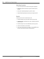
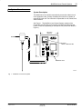
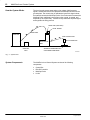
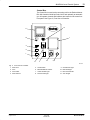
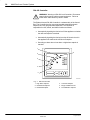
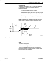
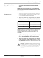
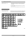
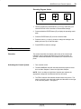
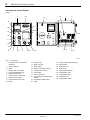
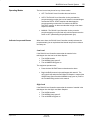
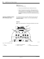
MultiPoint Level Control System Customer Product Manual Part 321 351A NORDSON CORPORATION D DULUTH, GEORGIA D USA www.nordson.com Nordson Corporation welcomes requests for information, comments and inquiries about its products. General information about Nordson can be found on the Internet using the following address: http://www.nordson.com. Address all correspondence to: Nordson Corporation Attn: Customer Service 11475 Lakefield Drive Duluth, GA 30097 Notice This is a Nordson Corporation publication which is protected by copyright. Original copyright date 2001. No part of this document may be photocopied, reproduced, or translated to another language without the prior written consent of Nordson Corporation. The information contained in this publication is subject to change without notice. Trademarks AccuJet, AquaGuard, Asymtek, Automove, Autotech, Blue Box, CF, CanWorks, Century, Clean Coat, CleanSleeve, CleanSpray, Compumelt, Control Coat, Cross-Cut, Cyclo-Kinetic, Dispensejet, DispenseMate, Durafiber, Durasystem, Easy Coat, Easymove Plus, Econo-Coat, EPREG, ETI, Excel 2000, Flex-O-Coat, FlexiCoat, Flexi-Spray, Flow Sentry, Fluidmove, Fluidshooter, FoamMelt, FoamMix, Helix, Horizon, Hose Mole, Hot Shot, Hot Stitch, Isocoil, Isocore, Iso-Flo, JR, KB30, Little Squirt, Magnastatic, MEG, Meltex, MicroSet, Millenium, Mini Squirt, Moist-Cure, Mountaingate, MultiScan, Nordson, OmniScan, Opticoat, Package of Values, PluraFoam, Porous Coat, PowderGrid, Powderware, Pro-Flo, ProLink, Pro-Meter, Pro-Stream, PRX, RBX, Ready Cost, Rhino, S. design stylized, Saturn, SC5, SCF, Select Charge, Select Coat, Select Cure, Shur-Lok, Slautterback, Smart-Coat, Spray Squirt, Spraymelt, Super Squirt, Sure-Bond, Sure Coat, System Sentry, Tela-Therm, Trends, Tribomatic, UniScan, UpTime, Veritec, Versa-Coat, Versa-Screen, Versa-Spray, Watermark, and When you expect more. are registered trademarks of Nordson Corporation. ATS, Auto-Flo, AutoScan, BetterBook, Chameleon, CanNeck, Check Mate, CPX, Control Weave, Controlled Fiberization, EasyClean, Ebraid, Eclipse, Equi=Bead, Fillmaster, Gluie, Ink-Dot, Kinetix, Maxima, MicroFin, Minimeter, Multifil, OptiMix, Pattern View, PluraMix, Primarc, Prism, Process Sentry, PurTech, Pulse Spray, Seal Sentry, Select Series, Sensomatic, Shaftshield, Spectral, Spectrum, Sure Brand, Swirl Coat, Vista, Walcom, and 2 Rings (Design) are trademarks of Nordson Corporation. 69–LVL–EH–IS–01 321 351A Issued 7/01 E 2001 Nordson Corporation All rights reserved Table of Contents i Table of Contents 1. Safety . . . . . . . . . . . . . . . . . . . . . . . . . . . . . . . . . . . . . . . . . . . . . . . . . . . . . 1 Safety Alert Symbols . . . . . . . . . . . . . . . . . . . . . . . . . . . . . . . . . . . . . . 1 Responsibilities of the Equipment Owner . . . . . . . . . . . . . . . . . . . . . 2 Safety Information . . . . . . . . . . . . . . . . . . . . . . . . . . . . . . . . . . . . . . 2 Instructions, Requirements, and Standards . . . . . . . . . . . . . . . . 2 User Qualifications . . . . . . . . . . . . . . . . . . . . . . . . . . . . . . . . . . . . . 3 Applicable Industry Safety Practices . . . . . . . . . . . . . . . . . . . . . . . . . 3 Intended Use of the Equipment . . . . . . . . . . . . . . . . . . . . . . . . . . . 3 Instructions and Safety Messages . . . . . . . . . . . . . . . . . . . . . . . . 4 Installation Practices . . . . . . . . . . . . . . . . . . . . . . . . . . . . . . . . . . . . 4 Operating Practices . . . . . . . . . . . . . . . . . . . . . . . . . . . . . . . . . . . . 5 Maintenance and Repair Practices . . . . . . . . . . . . . . . . . . . . . . . . 5 Equipment Safety Information . . . . . . . . . . . . . . . . . . . . . . . . . . . . . . 6 Equipment Shutdown . . . . . . . . . . . . . . . . . . . . . . . . . . . . . . . . . . . 6 Relieve System Hydraulic Pressure . . . . . . . . . . . . . . . . . . . . 6 De-energize the System . . . . . . . . . . . . . . . . . . . . . . . . . . . . . . 6 Disable the Gun . . . . . . . . . . . . . . . . . . . . . . . . . . . . . . . . . . . . . 7 General Safety Warnings and Cautions . . . . . . . . . . . . . . . . . . . . 7 Other Safety Precautions . . . . . . . . . . . . . . . . . . . . . . . . . . . . . . . 10 First Aid . . . . . . . . . . . . . . . . . . . . . . . . . . . . . . . . . . . . . . . . . . . . . . 10 2. System Overview . . . . . . . . . . . . . . . . . . . . . . . . . . . . . . . . . . . . . . . . . . 11 System Description . . . . . . . . . . . . . . . . . . . . . . . . . . . . . . . . . . . . 11 How the System Works . . . . . . . . . . . . . . . . . . . . . . . . . . . . . . . . . . . 12 System Components . . . . . . . . . . . . . . . . . . . . . . . . . . . . . . . . . . . . . 12 Control Box . . . . . . . . . . . . . . . . . . . . . . . . . . . . . . . . . . . . . . . . . . 13 RIA 450 Controller . . . . . . . . . . . . . . . . . . . . . . . . . . . . . . . . . . . . . 14 MultiCap Probe . . . . . . . . . . . . . . . . . . . . . . . . . . . . . . . . . . . . . . . 15 Lid Kit . . . . . . . . . . . . . . . . . . . . . . . . . . . . . . . . . . . . . . . . . . . . . . . 15 E 2001 Nordson Corporation All rights reserved 321 351A Issued 7/01 69-LVL-EH-IS-01 ii Table of Contents 3. Installation . . . . . . . . . . . . . . . . . . . . . . . . . . . . . . . . . . . . . . . . . . . . . . . . 16 Connecting the Feeding Unit to the H20 Gun . . . . . . . . . . . . . . . . 16 Connecting the Feeding Unit Without a Gun . . . . . . . . . . . . . . . . . 16 Connecting the H20 Gun to the Lid Kit/Applicator Unit . . . . . . . . . 16 Mounting the Level Control Cabinet . . . . . . . . . . . . . . . . . . . . . . . . 17 Wiring Instructions . . . . . . . . . . . . . . . . . . . . . . . . . . . . . . . . . . . . . . . 17 4. System Setup . . . . . . . . . . . . . . . . . . . . . . . . . . . . . . . . . . . . . . . . . . . . . 18 Verifying Program Values . . . . . . . . . . . . . . . . . . . . . . . . . . . . . . . . . 18 Resetting Program Values . . . . . . . . . . . . . . . . . . . . . . . . . . . . . . 19 5. Operation . . . . . . . . . . . . . . . . . . . . . . . . . . . . . . . . . . . . . . . . . . . . . . . . . 19 Overview . . . . . . . . . . . . . . . . . . . . . . . . . . . . . . . . . . . . . . . . . . . . . . . 19 Activating the Control System . . . . . . . . . . . . . . . . . . . . . . . . . . . . . 19 Operating Modes . . . . . . . . . . . . . . . . . . . . . . . . . . . . . . . . . . . . . . . . 21 Indicator Lamps and Alarms . . . . . . . . . . . . . . . . . . . . . . . . . . . . . . . 21 Low Level . . . . . . . . . . . . . . . . . . . . . . . . . . . . . . . . . . . . . . . . . . . . 21 High Level . . . . . . . . . . . . . . . . . . . . . . . . . . . . . . . . . . . . . . . . . . . 21 Operating the MultiCap Probe/ FEC 12 Electronic Insert . . . . . . . 22 Switches . . . . . . . . . . . . . . . . . . . . . . . . . . . . . . . . . . . . . . . . . . . . . 22 MultiCap Probe/FEC 12 Electronic Insert Calibration Procedures . . . . . . . . . . . . . . . . . . . . . . . . . . . . . . . . . 23 Calibration . . . . . . . . . . . . . . . . . . . . . . . . . . . . . . . . . . . . . . . . . . . . . . 23 6. Troubleshooting . . . . . . . . . . . . . . . . . . . . . . . . . . . . . . . . . . . . . . . . . . . 23 7. Schematics . . . . . . . . . . . . . . . . . . . . . . . . . . . . . . . . . . . . . . . . . . . . . . . 24 8. Parts . . . . . . . . . . . . . . . . . . . . . . . . . . . . . . . . . . . . . . . . . . . . . . . . . . . . . 27 Using the Illustrated Parts List . . . . . . . . . . . . . . . . . . . . . . . . . . . . . 27 Level Control Components . . . . . . . . . . . . . . . . . . . . . . . . . . . . . . . . 28 Lid Kit for FM 151 . . . . . . . . . . . . . . . . . . . . . . . . . . . . . . . . . . . . . . . . 30 Lid Kit for FM-190 . . . . . . . . . . . . . . . . . . . . . . . . . . . . . . . . . . . . . . . 31 69-LVL-EH-IS-01 321 351A Issued 7/01 E 2001 Nordson Corporation All rights reserved MultiPoint Level Control System 1 MultiPoint Level Control System 1. Safety Read this section before using the equipment. This section contains recommendations and practices applicable to the safe installation, operation, and maintenance (hereafter referred to as ”use”) of the product described in this document (hereafter referred to as “equipment”). Additional safety information, in the form of task-specific safety alert messages, appears as appropriate throughout this document. WARNING: Failure to follow the safety messages, recommendations, and hazard avoidance procedures provided in this document can result in personal injury, including death, or damage to equipment or property. Safety Alert Symbols The following safety alert symbol and signal words are used throughout this document to alert the reader to personal safety hazards or to identify conditions that may result in damage to equipment or property. Comply with all safety information that follows the signal word. WARNING: Indicates a potentially hazardous situation that, if not avoided, can result in serious personal injury, including death. CAUTION: Indicates a potentially hazardous situation that, if not avoided, can result in minor or moderate personal injury. CAUTION: (Used without the safety alert symbol) Indicates a potentially hazardous situation that, if not avoided, can result in damage to equipment or property. E 2001 Nordson Corporation All rights reserved 321 351A Issued 7/01 69–LVL–EH–IS–01 2 MultiPoint Level Control System Responsibilities of the Equipment Owner Equipment owners are responsible for managing safety information, ensuring that all instructions and regulatory requirements for use of the equipment are met, and qualifying all potential users. Safety Information S Research and evaluate safety information from all applicable sources, including the owner-specific safety policy, best industry practices, governing regulations, material manufacturer’s product information, and this document. S Make safety information available to equipment users in accordance with governing regulations. Contact the authority having jurisdiction for information. S Maintain safety information, including the safety labels affixed to the equipment, in readable condition. Instructions, Requirements, and Standards S Ensure that the equipment is used in accordance with the information provided in this document, governing codes and regulations, and best industry practices. S If applicable, receive approval from your facility’s engineering or safety department, or other similar function within your organization, before installing or operating the equipment for the first time. S Provide appropriate emergency and first aid equipment. S Conduct safety inspections to ensure required practices are being followed. S Re-evaluate safety practices and procedures whenever changes are made to the process or equipment. 69–LVL–EH–IS–01 321 351A Issued 7/01 E 2001 Nordson Corporation All rights reserved MultiPoint Level Control System 3 User Qualifications Equipment owners are responsible for ensuring that users: S Receive safety training appropriate to their job function as directed by governing regulations and best industry practices. S Are familiar with the equipment owner’s safety and accident prevention policies and procedures. S Receive, equipment- and task-specific training from another qualified individual. NOTE: Nordson can provide equipment-specific installation, operation, and maintenance training. Contact your Nordson representative for information. S Possess industry- and trade-specific skills and a level of experience appropriate to their job function. S Are physically capable of performing their job function and are not under the influence of any substance that degrades their mental capacity or physical capabilities. Applicable Industry Safety Practices The following safety practices apply to the use of the equipment in the manner described in this document. The information provided here is not meant to include all possible safety practices, but represents the best safety practices for equipment of similar hazard potential used in similar industries. Intended Use of the Equipment S Use the equipment only for the purposes described and within the limits specified in this document. S Do not modify the equipment. S Do not use incompatible materials or unapproved auxiliary devices. Contact your Nordson representative if you have any questions on material compatibility or the use of non-standard auxiliary devices. E 2001 Nordson Corporation All rights reserved 321 351A Issued 7/01 69–LVL–EH–IS–01 4 MultiPoint Level Control System Instructions and Safety Messages (contd) S Read and follow the instructions provided in this document and other referenced documents. S Familiarize yourself with the location and meaning of the safety warning labels and tags affixed to the equipment. Refer to Safety Labels in this section. S If you are unsure of how to use the equipment, contact your Nordson representative for assistance. Installation Practices S Install the equipment in accordance with the instructions provided in this document and in the documentation provided with auxiliary devices. S Ensure that the equipment is rated for the environment in which it will be used and that the processing characteristics of the material will not create a hazardous environment. Refer to the Material Safety Data Sheet (MSDS) for the material. S If the required installation configuration does not match the installation instructions, contact your Nordson representative for assistance. S Position the equipment for safe operation. Observe the requirements for clearance between the equipment and other objects. S Install lockable power disconnects to isolate the equipment and all independently powered auxiliary devices from their power sources. S Properly ground all equipment. Contact your local building code enforcement agency for specific requirements. S Ensure that fuses of the correct type and rating are installed in fused equipment. S Contact the authority having jurisdiction to determine the requirement for installation permits or inspections. 69–LVL–EH–IS–01 321 351A Issued 7/01 E 2001 Nordson Corporation All rights reserved MultiPoint Level Control System 5 Operating Practices S Familiarize yourself with the location and operation of all safety devices and indicators. S Confirm that the equipment, including all safety devices (guards, interlocks, etc.), is in good working order and that the required environmental conditions exist. S Use the personal protective equipment (PPE) specified for each task. Refer to Equipment Safety Information or the material manufacturer’s instructions and MSDS for PPE requirements. S Do not use equipment that is malfunctioning or shows signs of a potential malfunction. Maintenance and Repair Practices S Perform scheduled maintenance activities at the intervals described in this document. S Relieve system hydraulic and pneumatic pressure before servicing the equipment. S De-energize the equipment and all auxiliary devices before servicing the equipment. S Use only new factory-authorized refurbished or replacement parts. S Read and comply with the manufacturer’s instructions and the MSDS supplied with equipment cleaning compounds. NOTE: MSDSs for cleaning compounds sold by Nordson are available from Nordson’s Website at www.nordson.com or by calling Nordson Technical Support. S Confirm the correct operation of all safety devices before placing the equipment back into operation. S Dispose of waste cleaning compounds and residual process materials according to governing regulations. Refer to the applicable MSDS or contact the authority having jurisdiction for information. S Keep equipment safety warning labels clean. Replace worn or damaged labels. E 2001 Nordson Corporation All rights reserved 321 351A Issued 7/01 69–LVL–EH–IS–01 6 MultiPoint Level Control System Equipment Safety Information This part provides safety information applicable to the following types of Nordson equipment: S hot melt and cold adhesive application equipment, including melters, hoses, and guns. S auxiliary equipment, including pattern-controllers, timers, and other similar devices. Equipment Shutdown To safely complete many of the procedures described in this document, the user must first shut down the equipment. The level of shut-down required varies by the type of equipment in use and the procedure being completed. When required, shut-down instructions appear at the start of the procedure. Each level of shut-down is described below. Relieve System Hydraulic Pressure Completely relieve system hydraulic pressure before breaking any hydraulic connection or seal. Refer to the melter-specific product manual for instructions on relieving system hydraulic pressure. De-energize the System Isolate the system (melter, hoses, guns, and auxiliary devices) from all power sources before accessing any unprotected high-voltage wiring or connection point. 1. Turn off the equipment and all auxiliary devices connected to the equipment (system). 2. To prevent the equipment from being accidentally energized, lock and tag the disconnect switch(es) or circuit breaker(s) that provide input electrical power to the equipment and auxiliary devices. NOTE: Government regulations and industry standards dictate specific requirements for the isolation of hazardous energy sources. Refer to the appropriate regulation or standard. 69–LVL–EH–IS–01 321 351A Issued 7/01 E 2001 Nordson Corporation All rights reserved MultiPoint Level Control System 7 Disable the Gun All electrical or mechanical devices that provide an activation signal to the gun solenoid(s) or the melter pump must be disabled before work can be performed on or around a gun that is connected to a pressurized system. 1. Turn off or disconnect the gun triggering device (pattern controller, timer, PLC, etc.) 2. Disconnect the input signal wiring to the gun solenoid valve(s). 3. Reduce the air pressure to the gun solenoid valve(s) to zero; then relieve the residual air pressure between the regulator and the gun. General Safety Warnings and Cautions This part contains general safety warnings and cautions and first aid information applicable to the use of the equipment described in this document. WARNING: Hazardous vapors! Before processing any Polyurethane Reactive (PUR) hot melt or solvent-based material through a compatible Nordson melter, read and comply with the material’s MSDS. Ensure that the material’s processing temperature and flashpoints will not be exceeded and that all requirements for safe handling, ventilation, first aid, and personal protective equipment are met. Failure to comply with MSDS requirements can cause personal injury, including death. WARNING: Reactive material! Never clean any aluminum component or flush Nordson equipment with halogenated hydrocarbon fluids. Nordson melters and guns contain aluminum components that may react violently with halogenated hydrocarbons. The use of halogenated hydrocarbon compounds in Nordson equipment can cause personal injury, including death. E 2001 Nordson Corporation All rights reserved 321 351A Issued 7/01 69–LVL–EH–IS–01 8 MultiPoint Level Control System General Safety Warnings and Cautions (contd) WARNING: System pressurized! Relieve system hydraulic pressure before breaking any hydraulic connection or seal. Failure to relieve the system hydraulic pressure can result in the uncontrolled release of hot melt that can cause personal injury. WARNING: Molten Material! Wear eye or face protection, clothing that protects exposed skin, and heat-protective gloves when servicing equipment that contains molten hot melt. Even when solidified, hot melt can still cause burns. Failure to wear appropriate personal protective equipment can result in personal injury. WARNING: Equipment starts automatically! Remote triggering devices are used to control automatic hot melt guns. Before working on or near an operating gun, disable the gun’s triggering device and remove the air supply to the gun’s solenoid valve(s). Failure to disable the gun’s triggering device and remove the supply of air to the solenoid valve(s) can result in personal injury. WARNING: Risk of electrocution! Even when switched off and electrically isolated at the disconnect switch or circuit breaker, the equipment may still be connected to energized auxiliary devices. De-energize and electrically isolate all auxiliary devices before servicing the equipment. Failure to properly isolate electrical power to auxiliary equipment before servicing the equipment can result in personal injury, including death. WARNING: Risk of fire or explosion! Nordson cold adhesive equipment is not rated for use in explosive environments and should not be used with solvent-based adhesives that can create an explosive atmosphere when processed. Refer to the MSDS for the adhesive to determine its processing characteristics and limitations. The use of incompatible solvent-based adhesives or the improper processing of solvent-based adhesives can result in personal injury, including death. 69–LVL–EH–IS–01 321 351A Issued 7/01 E 2001 Nordson Corporation All rights reserved MultiPoint Level Control System 9 WARNING: Allow only personnel with appropriate training and experience to operate or service the equipment. The use of untrained or inexperienced personnel to operate or service the equipment can result in injury, including death, to themselves and others, and damage to the equipment. CAUTION: Hot surfaces! Avoid contact with the hot metal surfaces of guns, hoses, and certain components of the melter. If contact can not be avoided, wear heat-protective gloves and clothing when working around heated equipment. Failure to avoid contact with hot metal surfaces can result in personal injury. CAUTION: Some Nordson melters are specifically designed to process Polyurethane Reactive (PUR) hot melt. Attempting to process PUR in equipment not specifically designed for this purpose can damage the equipment and cause premature reaction of the hot melt. If you are unsure of the equipment’s ability to process PUR, contact your Nordson representative for assistance. CAUTION: Before using any cleaning or flushing compound on or in the equipment, read and comply with the manufacturer’s instructions and the MSDS supplied with the compound. Some cleaning compounds can react unpredictably with hot melt, resulting in damage to the equipment. CAUTION: Nordson hot melt equipment is factory tested with Nordson Type R fluid that contains Polyester Adipate plasticizer. Certain hot melt materials can react with Type R fluid and form a solid gum that can clog the equipment. Before using the equipment, confirm that the hot melt is compatible with Type R fluid. E 2001 Nordson Corporation All rights reserved 321 351A Issued 7/01 69–LVL–EH–IS–01 10 MultiPoint Level Control System Other Safety Precautions S Do not use an open flame to heat hot melt system components. S Check high pressure hoses daily for signs of excessive wear or damage. S Never point a dispensing handgun at yourself or others. S Suspend dispensing handguns by their proper suspension point. First Aid If molten hot melt comes in contact with your skin: 1. Do NOT attempt to remove the molten hot melt from your skin. 2. Immediately soak the affected area in clean, cold water until the hot melt has cooled. 3. Do NOT attempt to remove the solidified hot melt from your skin. 4. In case of severe burns, treat for shock. 5. Seek expert medical attention immediately. Give the MSDS for the hot melt to the medical personnel providing treatment. 69–LVL–EH–IS–01 321 351A Issued 7/01 E 2001 Nordson Corporation All rights reserved 11 MultiPoint Level Control System 2. System Overview System Description The MultiPoint Level Controller automatically senses the adhesive level in the applicator’s tank, thereby eliminating the need for an operator to manually fill each unit. The Controller is responsible for refill, shutoff, and alarm functions. See Figure 1. The MultiPoint Level Control System consists of the Control Box, the RIA 450 Level Controller, the MultiCap Probe and the Lid Kit. Lid kits vary depending on the specific unit (lid kit is not shown in Figure 1). 203.2 mm (8.00 in.) PROBE 323.9 mm (12.75 in.) MANUAL R1A 450 LEVEL CONTROLLER AUTO OFF MAN AUTO OVER NORMAL SILENCE ON UNDER OFF CONTROL BOX 6901001A Fig. 1 MultiPoint Level Control System E 2001 Nordson Corporation All rights reserved 321 351A Issued 7/01 69–LVL–EH–IS–01 12 MultiPoint Level Control System The level control process starts when a low voltage, high frequency signal is sensed and sent to the capacitance MultiCap Probe then to the ground plane. The control relay is calibrated to ignore this signal unless hot material contacts the MultiCap Probe. If hot melt material contacts the MultiCap Probe, additional current flows to the ground, is sensed, and amplified by the control relay. Internal circuitry reads this amplified signal and regulates the filling process. How the System Works FEED GUN (OPTIONAL) LEVEL PROBE FEED HOSE FEED UNIT APPLICATOR HOSE APPLICATOR APPLICATOR GUN UNIT LEVEL ADHESIVE DISPENSED ON CONTROL CUSTOMER SUBSTRATE BOX 6901004A Fig. 2 System Flow System Components The MultiPoint Level Control System consists of the following components. S S S S 69–LVL–EH–IS–01 Control Box RIA 450 Controller MultiCap Probe Lid Kit 321 351A Issued 7/01 E 2001 Nordson Corporation All rights reserved 13 MultiPoint Level Control System Control Box The Control Box is used as the connecting unit for the Endres+Hauser RIA 450 Controller, MultiCap Probe, lid kit, and optionally an automatic gun. All operator controls and indicators are located on the control box front panel. See Figure 3, Front View of Controller. 12 11 10 MANUAL 1 AUTO OFF MAN 9 OVER 8 NORMAL AUTO SILENCE ON 7 UNDER OFF 6 5 4 2, 3 6901002A Fig. 3 1. 2. 3. 4. Front View of Controller Alarm horn Fuse Fuse holder Alarm silencer E 2001 Nordson Corporation All rights reserved 5. 6. 7. 8. On/Off switch Manual/Off/Auto selector Under fill alarm light Normal mode light 321 351A Issued 7/01 9. 10. 11. 12. Overfill alarm light Manual fill light RIA 450 Controller Auto fill light 69–LVL–EH–IS–01 14 MultiPoint Level Control System RIA 450 Controller WARNING: Warning on RIA 450 Level Controller: Disconnect power before opening cabinet ground equipment. Failure to follow these instructions may result in death. The Endres+Hauser RIA 450 Controller is a subassembly of the Control Box. The Controller has four user programmable setpoints and each setpoint has a user programmable hysteresis. The Controller is responsible for refill, shutoff, and alarm functions as follows. S Automatically signaling the feed unit to fill the applicator unit when the refill start setpoint is reached. S Automatically signaling the feed unit to shut off when the level in the applicator unit reaches the refill shut off setpoint. S Sounding an alarm when a low alarm or high alarm setpoint is reached. 1 6 2 3 4 5 6901014A Fig. 4 RIA 450 Controller 1. High Alarm Setpoint 2. Refill Shutoff Setpoint 3. Refill Start Setpoint 69–LVL–EH–IS–01 321 351A Issued 7/01 4. Low Alarm Setpoint 5. Empty Calibration Point 6. Full Calibration Setpoint E 2001 Nordson Corporation All rights reserved 15 MultiPoint Level Control System MultiCap Probe The MultiCap Probe contains an FEC 12 electronic insert that functions as a transmitter for capacitance measurement. Capacitance measurement functions: S The MultiCap Probe and vessel form a capacitor. S Depending on the level, the space between these capacitor plates is filled either with air (empty vessel) or an unspecified quantity of material. S The initial capacitance for the empty vessel is low, but increases proportionally to the amount of material covering the MultiCap Probe. NOTE: The MultiCap Probe is shipped according to the specifications shown in Figure 5. The rod may be cut to a shorter length if needed. 117.6 mm (4.63 in.) 16.3 mm (.64 in.) 1 2 3 85.8 mm (3.38 in.) 19.1 mm (.75 in.) 76.2 mm (3.0 in.) Fig. 5 609.6 mm (24.0 in.) 6901003A MultiCap Probe 1. 3/4 NPT Connector 2. PTFE Covering 3. Stainless Steel Sensing Rod Lid Kit The Lid Kit is used as follows: S To mount the MultiCap Probe S To mount the hose or gun for refilling The original lid assembly is removed and a new applicator-specific replacement lid assembly is installed. Lid Kits vary according to the unit. Refer to the specific Parts List for details. E 2001 Nordson Corporation All rights reserved 321 351A Issued 7/01 69–LVL–EH–IS–01 16 MultiPoint Level Control System 3. Installation This section contains the installation procedures necessary to install the MultiPoint Level Control System for various applicators. Inventory and inspect the MultiPoint Level Control System components. The gun, solenoid, and filter/regulator are ordered and shipped separately. WARNING: Warning on RIA 450 Level Controller: Disconnect power before opening cabinet ground equipment. Failure to follow these instructions may result in death. 1. Remove the hinged lid and hopper enclosure from the applicator. S Refer to the applicator manual for detailed instructions and parts list. 2. Assemble the following components to the hopper enclosure using the fasteners supplied with this kit. S S S S Mounting plate Mounting spacer Hopper cover Loading kit 3. Install the hydraulic connectors to the hopper enclosure assembly. NOTE: The gun-to-cover connection is different than a hose-to-cover connection. These differences are shown in Figures 12 and 13. Connecting the Feeding Unit to the H20 Gun NOTE: Reference the H20 Gun Manual for connection instructions. Connecting the Feeding Unit Without a Gun If a Gun is not required: 1. Connect feed unit hose to the male connector 2. Connect male connector to the tank/hopper cover Connecting the H20 Gun to the Lid Kit/Applicator Unit 1. Connect the H20 gun to the adapter 2. Connect the adapter to the bushing 3. Connect the bushing to the tank cover 69–LVL–EH–IS–01 321 351A Issued 7/01 E 2001 Nordson Corporation All rights reserved MultiPoint Level Control System Mounting the Level Control Cabinet 17 1. Mount the level control cabinet in a location as far away as possible from vibration, corrosive atmosphere and potential mechanical damage. NOTE: in order to prevent signal drop-off, it is recommended that the level control cabinet be located as close as possible to the filling cabinet. (This instruction applies to the distance between the feed unit and the level control box). Wiring Instructions 1. Install two strain reliefs, one at each of the two holes in the bottom of the level control cabinet. Use the strain relief on the right for steps 2, 3, and 4. Use the strain relief on the left for step 5. 2. Using the wiring diagram in the Schematics section of this manual as a guide, connect a set of customer-supplied 22 AWG or 24 AWG wire leads inside the level control MultiCap Probe to XT1, inside the level control cabinet. Connect MultiCap Probe Wire To Control Box Panel #1 XT1 – #8 #2 XT1 – #9 #3 XT1 –#10 NOTE: The level control cabinet can be located up to 1,000 m from the MultiCap Probe assembly when 18 AWG is used. (This instruction applies to the distance between the MultiCap Probe and the Level Control Box). 3. Using the wiring diagram in the Schematics section of this manual as a guide, connect the pair of customer-supplied 22 AWG or 24 AWG wire leads from terminals XT1-4 and XT1-5, in the Control Box, to the feed unit. See feed unit applicator manual for the wiring position. 4. Using the wiring diagram in the Schematics section of this manual as a guide, connect the 120 VAC gun solenoid valve leads to XT1-6 and XT1-7, inside the level control cabinet. See feed unit manual for hose and gun connections. WARNING: This equipment contains electrical potentials that are dangerous and could be fatal. Disconnect and lock out input electrical power before connecting the input power supply line to this unit. Failure to observe and follow this warning could cause death. E 2001 Nordson Corporation All rights reserved 321 351A Issued 7/01 69–LVL–EH–IS–01 18 MultiPoint Level Control System Wiring Instructions (contd) 5. Route a 1-phase, 120 VAC input power supply line through the strain relief and connect it to terminals XT1-1 and XT1-2 inside the level control cabinet. 6. Connect the input power supply line ground wire to XT1-3 inside the level control cabinet. 7. Refer to feed unit manual and applicator manuals for specific setups. 4. System Setup Verifying Program Values Fig. 6 The RIA 450 Level Controller is pre-programmed prior to shipping. Check the program settings to confirm the correct settings. If the settings are not correct, reset per the Pre-set Programming Values listed in Figure 6. Preset Programming Values 69–LVL–EH–IS–01 321 351A Issued 7/01 E 2001 Nordson Corporation All rights reserved 19 MultiPoint Level Control System Resetting Program Values 1 2 3 6901015A 1. Use the programming buttons Minus (1), Plus (2), and Enter (3) to reset the RIA 450 Level Controller to recommended settings. 2. Press and hold the ENTER button (E) to display the operating matrix table. 3. Press the ENTER button (E) to move across the table. 4. Press the minus (–) or plus (+) button to change the settings in the display and move up or down the table. 5. Press ENTER to retain the settings. 5. Operation Overview This section describes the location and function of the controls and indicators used to operate the MultiPoint Level Control system. All operator controls and indicators are located on the control box front panel. Activating the Control System 1. Turn controller to ON. 2. The white NORMAL lamp will illuminate unless the system is below the Low Alarm Setpoint or above the High Alarm Setpoint. NOTE: If the Low Alarm or High Alarm Setpoints are reached, the appropriate red light will illuminate and the horn will sound. 3. The FEC12 has two slide switches located near the top center. The switch on the left is set to the right position and the switch on the right is set to the left position. See figure 8. E 2001 Nordson Corporation All rights reserved 321 351A Issued 7/01 69–LVL–EH–IS–01 20 MultiPoint Level Control System Activating the Control System (contd) 22 5 24 25 1 2 19 27 26 20, 23 AUTO 14 G 13 12 11 10 9 MANUAL 14 G 13 12 11 10 9 18 21, 22 14 G 13 12 11 10 9 OFF 28 MAN AUTO OVER 8 4 7 3 6 2 5 1 8 4 7 3 6 2 5 1 8 4 7 3 6 2 5 1 9 NORMAL SILENCE ON UNDER 29 OFF 8 30 7 3, 4 6 14, 15 12, 13 16, 17 10, 11 6901010A Fig. 7 Control Box 1. Level RIA 450 Level Controller Enclosure 2. Panel Enclosure 3. Switch 4. Manual, Auto, Off Legend 5. Level Controller (RIA 450) 6. Manual On/Off switch 7. Lamp Indicator, Under, Red 8. Lamp Indicator, White 9. Lamp Indicator, Over, Red 10. Relay 69–LVL–EH–IS–01 11. 12. 13. 14. 15. 16. 17. 18. Socket, relay Block, Terminal Strip, marker Switch, Push Button, Silence Legend Plate, Silencer Fuse Holder Fuse, Fast Acting Lamp Indicator, Round, Amber, Manual 19. Auto Mode Indicator Lamp 20. Alarm 321 351A Issued 7/01 21. 22. 23. 24. 25. 26. 27. 28. 29. Tag, warning, disconnect power Tag, Nordson Suppressor, arc Relay Timer Legend Plate, Manual Legend Plate, Auto Legend Plate, Over Suppressor, arc Legend Plate, Under E 2001 Nordson Corporation All rights reserved MultiPoint Level Control System Operating Modes 21 The level control may be set for any of three modes: S OFF: The RIA 450 Level Controller does not function. S AUTO: The RIA 450 Level Controller circuitry activates the pump/automatic gun when the level of material in the tank/hopper reaches the REFILL START setpoint and deactivates the pump/automatic gun when the level reaches the REFILL SHUTOFF setpoint. An alarm sounds when a high or low alarm setpoint is reached. S MANUAL: The RIA 450 Level Controller circuitry turns the pump/automatic gun on (fills feed unit) until the operator sets the switch to OFF (deactivating the pump/automatic gun). Indicator Lamps and Alarms When set to Auto, the RIA 450 Level Controller normally activates the pump/automatic gun as required and the Normal lamp on the enclosure door stays on. Low Level If the RIA 450 Level Controller senses that the material in the tank/hopper is at the Low Level Alarm Setpoint: S The ALARM sounds. S The NORMAL lamp goes off. S The red UNDER lamp goes on. The equipment operator must: S Press the horn SILENCE button to deactivate the alarm. S Begin the Refill process in the tank/hopper with material. The refill unit will stop when the Refill Shut Off Setpoint is reached (the UNDER lamp goes off and the NORMAL lamp goes on). Refer to the Troubleshooting section in this manual. High Level If the RIA 450 Level Controller senses that the amount of material in the tank/hopper is at the High Level Alarm Setpoint: S The ALARM sounds. S The NORMAL lamp goes off. S The red OVER lamp goes on. E 2001 Nordson Corporation All rights reserved 321 351A Issued 7/01 69–LVL–EH–IS–01 22 MultiPoint Level Control System High Level (contd) The equipment operator must: S Press the Horn SILENCE button to deactivate the alarm. S Stop the fill process that caused the overfilling and lower the amount of material in the tank/hopper to the Refill Start Setpoint (the OVER lamp goes off, the NORMAL lamp goes on and the RIA 450 Level Controller will activate the pump/automatic gun as required. Operating the MultiCap Probe/ FEC 12 Electronic Insert For operating instructions on the FEC 12 Electronic Insert, open the cover with a screwdriver. Inside the cover are symbols describing operating procedures. Switches NOTE: Verify switch positions. Both switches should be set to center. 1 – + – + 2 6 3 1 – 2 3 + 4 + 5 – 4...20 mA 4 5 6901009A Fig. 8 FEC 12 Electronic Insert 1. Lid 2. Switches 69–LVL–EH–IS–01 3. Pushbuttons (full calibration) 4. Ammeter connection 321 351A Issued 7/01 5. LED 6. Pushbuttons (empty calibration) E 2001 Nordson Corporation All rights reserved MultiPoint Level Control System Calibration 23 MultiCap Probe/FEC 12 Electronic Insert Calibration Procedures Calibration is carried out at the FEC 12 Electronic Insert by using four pushbuttons. (See Figure 8). 1. Press the two push buttons on the left of the MultiCap Probe simultaneously (6) when the material is just touching the bottom of MultiCap Probe to set low point. 2. Press and hold the 2 push buttons (6) until LED illuminates (5). 3. Reset level in hopper to high point and press two push buttons on the right simultaneously (3) until the LED illuminates. NOTE: The high and low points are 100% and 0% on the read out. NOTE: Refer to the Endress+Hauser website (www.Endress.com) for detailed calibration procedures. 6. Troubleshooting Problem 1. 2. Applicator Tank/Hopper Does Not Fill Unit Under fills or Overfills E 2001 Nordson Corporation All rights reserved Possible Cause Corrective Action System Incorrectly wired Check System Wiring. Incorrect voltage or no voltage to Level Controller Confirm 120V between XT1-1 and XT1-2. Fuse F1 is blown Replace fuse. Level Control power switch turned off Switch power on. Level Control Mode switch set to OFF Switch level control mode switch to Auto or Manual. Feed Applicator is empty Fill Feed Applicator. Feed Applicator, hose and gun has not reached setpoint or system ready Allow feed applicator to reach setpoint/system ready. See Feed Applicator Manual for more information. Feed Applicator Gun Solenoid has failed Replace Solenoid. Level Control MultiCap Probe out of Calibration Clean MultiCap Probe and re-calibrate. Setpoint in RIA 450 not set for unit size Review setpoints of RIA 450. Adhesive has change from original Recalibrate with new adhesive. (Underfill) Feed Applicator out of material Fill Feed Applicator. 321 351A Issued 7/01 69–LVL–EH–IS–01 24 MultiPoint Level Control System 7. Schematics SW230 1 2 ALARM 211 210D 230B SILENCE 60G 60D 60F 60E LT270 AUTO LT280 MAN 70A MANUAL 2 OFF 70B 1 3 SW40 4 270 AUTO 280 70C 60A 300A 280 270 291 70D 70E 2 2 4 4 1 1 60A 3 3 SW40 251B 290B 290A 50 250 F1 70A 1 AMP NO 1 2 NO 3 4 L1 N RCA LT190 GND3 180C OVER LT160 150C 60D NORMAL 60C LT200 201 UNDER 60B 9 10 11 12 4 14 3 8 G 2 7 13 1 6 GND3 CR170 5 70L 250 291 160 190 251A 300B GND2 170 GND4 GND1 60L 60M 160 150C 150B 150B 150A 4 3 70E 7 8 4 5 1 6 2 56 N/L– PE S 11 13 13 14 15 81 82 60G 60H GND1 (J1) P1 P2 12 8 180B 201 70N L/L+ 60K 60J 3 CR180 14 7 10 11 2 9 6 G 1 13 5 10 11 12 180B 180C 180A 200 9 190 210A 210B 70H 70G 150A 41 42 43 44 45 46 51 52 53 54 55 LEVEL CONTROL RIA 450 6 180A 70F 70G 70J 70H 170 5 6 7 5 L/C PROBE 2 4 SOLENOID 70F CR150 200 210A 70N 70J 60K 60L 3 CLUTCH L1 N GND3 GND2 290A 300A 300B RCA 60M 251B 251A P1 P2 GND4 8 2 AC–NEUT (120V) GND 1 1 AC–HOT TB1 (120V) 230A 230B G 10 11 12 14 4 9 8 CR230 3 13 7 210D 210C 230A 211 60J 60H 210B 210C 6901006A Fig. 9 Multi Point Level Control System Wiring Diagram 69–LVL–EH–IS–01 321 351A Issued 7/01 E 2001 Nordson Corporation All rights reserved XT1–1 3 1 L1 50 F1 (1 AMP) 70 13 PE 13 81 11 60 (J1) GND4 LEVEL CONTROL RIA 450 N/L– L/L+ SW 40 IN COMING POWER 120 VAC GND1 P1 P2 XT1–9 (TO PROBE) XT1–10 4 2 XT1–2 N 60 XT1–3 70 70 70 70 70 70 70 70 70 70 XT1–4 52 53 RIA 450 45 46 RIA 450 43 42 RIA 450 5 CR150 7 7 6 CR150 CR180 11 7 1 3 1 3 1 2 4 2 4 2 200 210 210 291 251 150 170 180 10 CR180 2 4 12 CR230 2 SW230 1 SILENCE 12 CR170 8 300 300 XT1–5 280 270 CR230 210 7 11 SW250 OFF MAN. AUTO CR170 250 251 4 3 7 11 290 290 To feed unit pump switch 150 180 201 211 230 1 8 CR150 LT160 14 CR170 13 14 CR180 13 LT190 LT200 RCA 14 CR230 13 EXT. LOCATION XT1–7 XT1–6 RCA LT270 LT280 60 60 60 60 60 60 60 60 60 60 60 60 60 HIGH ALARM ”OVER” LIGHT NORMAL FILL LOW ALARM ”UNDER” LIGHT ”AUTO” LIGHT FILL SOLENOID ALARM SILENCE ALARM ”NORMAL” LIGHT 6901007A ”MANUAL” LIGHT 69–LVL–EH–IS–01 321 351A Issued 7/01 E 2001 Nordson Corporation All rights reserved XT1–8 25 MultiPoint Level Control System Fig. 10 Schematics NOTE: Reference Feed Unit Manual for Pump Switch connections. 26 MultiPoint Level Control System This page left intentionally blank. 69–LVL–EH–IS–01 321 351A Issued 7/01 E 2001 Nordson Corporation All rights reserved 27 MultiPoint Level Control System 8. Parts To order parts, call the Nordson Customer Service Center or your local Nordson representative. Use the parts list, and the accompanying illustration, to describe and locate parts correctly. Using the Illustrated Parts List Numbers in the Item column correspond to numbers that identify parts in illustrations following each parts list. The code NS (not shown) indicates that a listed part is not illustrated. A dash (—) is used when the part number applies to all parts in the illustration. The number in the Part column is the Nordson Corporation part number. A series of dashes in this column (- - - - - -) means the part cannot be ordered separately. The Description column gives the part name, as well as its dimensions and other characteristics when appropriate. Indentions show the relationships between assemblies, subassemblies, and parts. Item Part Description Quantity — 000 0000 Assembly 1 1 000 000 S Subassembly 2 2 000 000 S S Part 1 Note A S If you order the assembly, items 1 and 2 will be included. S If you order item 1, item 2 will be included. S If you order item 2, you will receive item 2 only. The number in the Quantity column is the quantity required per unit, assembly, or subassembly. The code AR (As Required) is used if the part number is a bulk item ordered in quantities or if the quantity per assembly depends on the product version or model. Letters in the Note column refer to notes at the end of each parts list. Notes contain important information about usage and ordering. Special attention should be given to notes. E 2001 Nordson Corporation All rights reserved 321 351A Issued 7/01 69–LVL–EH–IS–01 28 MultiPoint Level Control System Level Control Components Item See Figure 11. Part Description Quantity Note 342886 MultiCap Probe 1 342884 Control Unit 1 1 ------ Enclosure, Level Control, 12 x 10 x 8 1 2 ------ Panel, Enclosure, L/C 1 3 181240 Switch, 3 Pos, Man, Spring Return 1 4 815328 Plate, Legend, Man, Off, Auto 1 5 342869 Controller, L/C, E-H 1 6 809128 Switch, 2 Pos, Dpst, Rocker, On/Off 1 7 ------ Lamp, Indicator, Round, Red 1 A 8 ------ Lamp, Indicator, Round, White 1 B A 9 ------ Lamp, Indicator, Round, Red 1 10 805175 Relay, 120 VAC, 4 PDT 3 11 805176 Socket, Relay 3 12 805218 Block, Terminal, 12 STA, 30 Amp 1 13 805219 Strip, Marker, 12 STA 1 14 939354 Switch, Push Button, Start 1 15 809130 Legend Plate, Silence 1 16 1-1/ 806797 Fuse Holder, 13-32 x 17 939062 Fuse, KLK, Fast Acting 1 18 ------ Lamp, Indicator, Round, Amber 1 C 19 ------ Lamp, Indicator, Round, Amber 1 C 20 804572 Alarm, 120V, 60Hz, .18 Amps 1 21 271880 Tag, Warning, Disconnect Power 1 22 153898 Tag, Nordson Oval 1 23 272620 Suppressor, Arc, w/Terminal 2 24 816463 Relay Timer, SS, 0.1 to 10 sec 1 25 240674 Tag, Ground 2 26 ------ Legend Plate, Manual 1 27 ------ Legend Plate, Auto 1 28 ------ Legend Plate, Over 1 29 ------ Legend Plate, Normal 1 30 ------ Legend Plate, Under 1 NOTE 2 1 A: Newark Part Number 93F3536 B: Newark Part Number 93F3539 C: Newark Part Number 93F3537 69–LVL–EH–IS–01 321 351A Issued 7/01 E 2001 Nordson Corporation All rights reserved MultiPoint Level Control System 22 5 1 24 25 29 2 19 27 26 20 AUTO 4 3 4 7 8 23 14 G 13 12 11 10 9 MANUAL 14 G 13 12 11 10 9 18 14 G 13 12 11 10 9 OFF 28 MAN AUTO 21 OVER 6 2 1 5 8 3 7 6 2 1 5 3 4 7 8 6 2 1 5 9 22 NORMAL SILENCE ON UNDER 29 OFF 8 30 7 3 4 6 14 16 15 17 12 10 13 11 6901008A Fig. 11 Level Control Mounting Hardware Kit for the FM-151 Applicator E 2001 Nordson Corporation All rights reserved 321 351A Issued 7/01 69–LVL–EH–IS–01 30 MultiPoint Level Control System Level Control Mounting Hardware Kit Parts List (for FM-151 Applicator) Lid Kit for FM 151 Item Part Description Quantity 809786 Kit H/W, Mounting, Level Control, FM-151 Version 1 981906 Screw, Socket Head Cap, 1/4-20 x 0.75 in. (Kit P/N 809786) 8 2 983140 Lockwasher, Split, 0.25 in. (Kit P/N 809786) 18 3 809783 Plate, Mounting, Level Control 1 4 809784 Spacer, Mounting, Level Control 1 1/ 5 981233 Screw, Socket Head, 6 809785 Cover, Tank, LC, Endres+Hauser (Kit P/N 809786) 1/ 4 - 20 x 1.00 in. 7 981233 Screw, Socket Head, 8 241889 Lid, Loading 9 803068 Adapter, Slot Nozzle, H20 4 Ref 8 1 - 20 x 1.00 in. (Kit P/N 809786) 2 1 1 3/ 10 973562 Bushing, Pipe, Hydraulic, 11 972622 Connector, Male, 37”, 11/16-12 x 3/8 NPT 1 12 972055 Connector, Male 1 8 x 1/ 4 (Kit P/N 809786 only) 1 1 2 9 3 12 11 10 4 2 8 5 14 6 7 2 13 6901013A Fig. 12 Lid Kit 151 69–LVL–EH–IS–01 321 351A Issued 7/01 E 2001 Nordson Corporation All rights reserved 31 MultiPoint Level Control System Level Control Mounting Hardware Kit Parts List (FM-190 Applicator) Lid Kit for FM-190 Item Part Description 100787 Kit Mounting E-H Level Control, FM-190 1 100789 Cover, Hopper (Kit P/N 100 787) 2 1/ 1 Screw, Fillister Head, 3 983140 Lock Washer, Split, 1/ 4 972055 Connector, Male 1 5 972622 Connector, Male, 37” 11/16-12 x 3/8 NPT 1 6 803068 Adapter, Slot Nozzle, H2O 1 2 2 4 7 973979 Adapter, SAE, 8 241889 Lid, Loading 1 9 981737 Screw, Soc, 10-32 x 2.00 (Kit P/N 100 787) 4 10 983120 Lock Washer, Split, #10 4 8 x 1/ x 0.375 in. Ref 981237 3/ 4-20 Quantity 4 (for kit P/N 100787) 1 6 7 4, 5 2, 3 8 9, 10 1 6901012A Fig. 13 Lid Kit 190 E 2001 Nordson Corporation All rights reserved 321 351A Issued 7/01 69–LVL–EH–IS–01 32 MultiPoint Level Control System 69–LVL–EH–IS–01 321 351A Issued 7/01 E 2001 Nordson Corporation All rights reserved