1
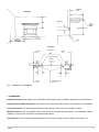
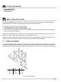
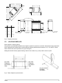
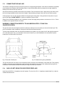
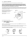
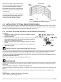
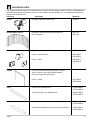
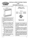
INSTALLATION AND OPERATING INSTRUCTIONS
EMPIRE COMFORT SYSTEMS, INC.
UNIVERSAL FIREPLACE FOR ALL
VENT-FREE LOG SYSTEMS
MODELS:
VFFB-36D Non-Circulating - Black Hood
VFFB-42D Non-Circulating - Black Hood
Effective Date
April, 2001
NON-CIRCULATING
APPLIANCES CAN BE
CONVERTED TO USE
LOUVER OPTIONS
SEE PAGE 14
WARNING: If the information in this manual is
not followed exactly, a fire or explosion may
result causing property damage, personal injury
or loss of life.
WHAT TO DO IF YOU SMELL GAS
- Do not try to light any appliance.
- Do not touch any electrical switch; do not
use any phone in your building.
- Immediately call your gas supplier from a
neighbor’s phone. Follow the gas supplier’s
instructions.
- If you cannot reach your gas supplier, call
the fire department.
• A qualified installer, service agency or the
gas supplier must perform installation and
service of the Vent-Free gas log heater.
FOR USE ONLY
WITH DECORATIVE TYPE
UNVENTED ROOM HEATERS
• Do not store or use gasoline or other
flammable vapors and liquids in the vicinity
of this or any other appliance.
DO NOT BUILD A WOOD FIRE.
DO NOT ATTEMPT TO MODIFY OR ALTER THE
CONSTRUCTION OF THE APPLIANCE OR ITS
COMPONENTS. ANY MODIFICATION OR
ALTERATION OF CONSTRUCTION MAY VOID
THE WARRANTY OF THESE UNITS.
CHILDREN AND ADULTS SHOULD BE
ALERTED TO THE HAZARDS OF HIGH
SURFACE TEMPERATURE and SHOULD
STAY AWAY TO AVOID BURNS OR CLOTHING
IGNITION.
YOUNG CHILDREN SHOULD BE CAREFULLY
SUPERVISED WHEN THEY ARE IN THE SAME
ROOM AS THE APPLIANCE.
R-5010
WARNING: Improper installation, adjustment,
alteration, service or maintenance can cause
injury or property damage. Refer to this manual.
For assistance or additional information,
consult a qualified installer, service agency or
the gas supplier.
Carefully review the instructions supplied
with the decorative type unvented room heater
for the minimum fireplace size requirement.
DO NOT INSTALL THE APPLIANCE IN
THIS FIREBOX, UNLESS THIS FIREBOX
MEETS THE MINIMUM DIMENSIONS REQUIRED
FOR THE INSTALLATION.
1
TABLE OF CONTENTS
PAGE
A
GENERAL INFORMATION
2
B
OPTIONAL ACCESSORIES
4
C
INSTALLATION OF FIREPLACE
4
D
INSTALLATION OF OPTIONAL ACCESSORIES
7
E
INSTALLATION OF YOUR VENT-FREE GAS LOG HEATER
10
F
MAINTENANCE
10
G
ACCESSORY PARTS
11
H
REPLACEMENT PARTS
12
A
GENERAL INFORMATION
The installation must conform with local codes or, in the absence of local codes, with the National Fuel Gas
Code, ANSI Z223.1 (latest edition) and to the National electrical Code, ANSI/NFPA70 (latest edition).
NOTE: Installation and repair should be done by a qualified service person. The appliance should be
inspected before use and at least annually by a qualified service person. More frequent cleaning may be
required due to excessive lint from carpeting, bedding material, etc. It is imperative that control compartment,
burners and circulating air passageways of the appliance be kept clean.
Any safety screen or guard removed for servicing an appliance must be replaced prior to operating the
appliance. Provide adequate combustion and ventilation air.
The flow of combustion and ventilation air MUST NOT be obstructed.
Provide adequate clearance around air openings into the combustion chamber and adequate accessibility
clearance for servicing and proper operation. NEVER obstruct the front opening of the appliance.
INSTALLATION PRECAUTIONS
This Empire Comfort Systems, Inc. fireplace and its components have been tested and will operate safely when installed in
accordance with this installation manual. Read all instructions before starting installation, then follow these instructions
carefully during installation to maximize fireplace benefit and safety. Report to your dealer any parts damaged in shipment.
The Empire Comfort Systems, Inc. warranty will be voided by, and Empire Comfort Systems, Inc. disclaims any
responsibility for the following actions:
- Installation of any damaged fireplace.
- Modification of the fireplace or any of the components parts thereof.
- Installation other than as instructed by Empire Comfort Systems, Inc.
- Installation and/or use of any component part or accessory not approved by Empire Comfort Systems, Inc. in
combination or assembly with a Empire Comfort Systems, Inc. fireplace, not withstanding any independent
testing laboratory or other third party approval of such component part or accessory.
Any such action may create a possible fire hazard.
Consult your local building codes.
Fireplace Screen.
The fireplace screen must be in place when the fireplace is operating.
2
R-5010
FINISHED
WALL
VFFB-36/42
8”
STAND-OFF
42” MIN.
FLAT
MANTEL
SHELF
3”
6” FROM
INSIDE EDGE
OF OPENING
11” MIN. CLEARANCE
HOOD
TOP VIEW
OUTER CASING
FINISHED
WALL
MANTEL
TRIM
FIREBOX
FIRE BOX
16" ON 36
19" ON 42
5”
MANTEL
TRIM
5”
NON-COMBUSTIBLE
MATERIAL
Fig. 1. Clearances to combustibles.
1. CLEARANCES.
Sidewall Clearances: The clearance from the inside of the fireplace to any combustible wall should not be less than 6”.
Fireplace Side and Back Clearances: The fireplace outer casing sides and back have zero clearance to combustibles.
Ceiling Clearances: The ceiling height should not be less than 42” from the top of the fireplace opening.
Mantel Clearances: Vent free fireplace models must use the hood supplied with the fireplace. If a combustible mantel is
installed, it must meet the clearance requirements detailed above.
Grate Clearance: The minimum clearance between the front legs of the grate and front edge of the fireplace is 2”.
R-5010
3
B
OPTIONAL ACCESSORIES.
- Simulated Brick Panels
- Polished Brass Hood
- Extended Hoods
C
INSTALLATION INSTRUCTIONS.
In planning the installation for the fireplace, it is necessary to determine where the unit is to be installed and whether
optional accessories are desired. Gas supply piping should also be planned at this time.
The fireplace can be mounted on any of these surfaces:
1. A flat hard combustible or non-combustible surface.
2. A raised platform of combustible or non-combustible material.
3. Four (4) corners of the fireplace so contact is made on all four perimeter edges on the bottom of the unit. (Example:
Four (4) concrete masonry blocks.)
If the fireplace is installed directly on carpeting, tile or other combustible material other than wood flooring, it should be
installed on a metal or wood panel extending the full width and depth of the unit.
At this point, you should have decided what components to include in your installation, and where the fireplace is to be
located. If this has not been done, stop and consult your dealer for assistance with this planning.
C-1.
FIREPLACE FRAMING.
Fireplace framing can be built before or after the fireplace is set in place. Framing should be positioned to accommodate
wall covering and fireplace facing material. The fireplace framing should be constructed of 2 x 4 lumber or heavier. The
framing headers may rest on the top of the fireplace standoffs. Refer to Fig. 2 and Fig. 3 for fireplace framing dimensions.
A
B
A
B
C
C
36
42
39-1/4"
39-1/4"
21-1/4"
41-1/4"
45-1/4"
24-1/4"
Fig. 2. Framing dimensions.
4
R-5010
L
E
F
K
D
M
STANDOFF
J
36
42
D
39"
45"
E
27 3/4"
32"
F
21"
24"
G
36"
42"
H
22"
24"
I
36"
38"
J
39"
41"
K
49 3/4"
56 3/4"
L
49 3/4"
56 3/4"
M
70 1/4"
80 3/8"
FRESH AIR
SYSTEM INTAKE
I
H
GAS LINE
OPENING
G
ELECTRICAL
CONNECTION
OPENING
GAS LINE
OPENING
Fig. 3. Fireplace dimensions.
C-2.
LOCATING FIREPLACE.
Place fireplace in framing opening.
Using the four (4) nailing tabs provided on the fireplace, attach two (2) tabs on each side. Attach tabs through prepunched
holes. Additional hole locations will be used for different finishing material with thicknesses of 1/2”, 5/8” and 3/4”. Attach
these materials with screws provided, two (2) per nailing tab.
Nailing tabs should fit directly against framing material. Use at least one (1) nail per tab to secure in place.
NAIL SIDE
THROUGH
FASTENING
TABS
NAIL SIDE
THROUGH
FASTENING
TABS
NAIL OR OTHER
SUITABLE
FASTENER
Fig. 4. Fasten fireplace in place with tabs.
R-5010
5
C-3.
CONNECTING THE GAS LINE.
The fireplace is designed to accept a 3/8-inch gas line for an approved gas fireplace. Have the line installed by a qualified
service person in accordance with all building codes. Consult local building codes to properly size the gas supply line
leading to the 3/8-inch hook-up at the unit.
Gas access holes are provided on both sides of the fireplace. Flex line should be used, if approved by local codes, when
the line is being installed in the left side of the fireplace. Hard plumbing could get in the way of the air dilution system.
Check gas type. Use only the gas type indicated on the gas log set rating plate. If the gas listed on the plate is not your
type of gas supply, DO NOT INSTALL. Contact your dealer for proper model.
Always use an external regulator for all LP fireplaces to reduce the supply tank pressure to a maximum of 14” w.c. This is
in addition to the regulator fitted to the heater.
WARNING: CONNECTION DIRECTLY TO AN UNREGULATED L.P. TANK CAN
CAUSE EXPLOSION.
The gas line comes into the fireplace under the hearth pan, although it is not necessary to remove the hearth pan. This
pan is removable to make installation of the gas line and all the accessories easier.
To remove the hearth pan, back out all screws that hold the pan in place, ten (10) screws for 42” and eight (8) screws for
36” in the bottom pan, one (1) on each side of the surround. (See Fig. 5). After installation of all accessories, replace
hearth pan in reverse order of its removal.
INSIDE WALL
OF FIREPLACE
1”
2”
2”
HEARTH
PAN
Fig. 5. Removal of hearth pan.
FRONT
EDGE
2”
Fig. 6. Clearances for gas log installation.
The gas line should be run directly to the bulkhead connector located in the middle/back of the hearth pan. This plumbing
should be connected, using all approved unions and shut-offs installed in the system. After making the proper gas line
connection to the bulkhead, reinstall the hearth pan using the screws you removed.
C-4.
GAS LOG SET SIZING FOR VENT-FREE FIREPLACE.
Install only a ANSI Z21.11.2 appliance into this fireplace. The size of the Z21.11.2 appliance should follow Fig. 6 and the
clearances shown above.
6
R-5010
C-5.
ELECTRICAL CONNECTION.
The VFFB36/42D with optional fan requires 120 VAC electrical hookup to the electrical box (installed).
CAUTION: ALL WIRING SHOULD BE DONE BY A QUALIFIED ELECTRICIAN AND SHALL BE IN COMPLIANCE
WITH ALL LOCAL, CITY AND STATE BUILDING CODES. BEFORE MAKING THE ELECTRICAL CONNECTION,
MAKE SURE THAT MAIN POWER SUPPLY IS DISCONNECTED. THE APPLIANCE, WHEN INSTALLED, MUST BE
ELECTRICALLY GROUNDED IN ACCORDANCE WITH LOCAL CODES OR, IN THE ABSENCE OF LOCAL CODES,
WITH THE NATIONAL ELECTRICAL CODE ANSI/NFPA 70 (LATEST EDITION).
A factory installed electrical box is located on the lower right hand side of the fireplace. Wiring must be fed to the electrical
box and attached to the receptacle that you must provide. Remove the knockout in the installed junction box to accept
wiring into the junction box. Install a UL listed cable clamp (not supplied) in the knockout hole. Leave approximately 6” of
wire in the junction box for connection.
Attach black wire to one side of the receptacle and
white wire to opposite side of receptacle.
The ground wire should be attached to the
green (neutral) screw.
JUNCTION
BOX
NEUTRAL
BLACK
WHITE
GROUND
Install the receptacle into the metal box.
Attach cover plate.
Fig. 7. Electrical junction box connection.
C-6.
OPTIONAL FRESH AIR INTAKE KITS
MODEL: VFFB-AK-36
VFFB-AK-42
Installation of our 6" fresh air intake kit is simple and easy to complete. This system MUST BE installed before the fireplace is enclosed with finishing material.
Install model VFFB-AK-36 on VFFB-36D. Install model VFFB-AK-42 on VFFB-42D. The air will be drawn into the cooling
layer of the fireplace and be completely separated from the combustion casing of the vent-free fireplace.
Cooler outside air will mix with room air, circulating around the firebox to reduce the heat output and bring heated, fresh
air into the house to provide a more positive balance.
INSULATED
DUCT
Fig. 8. Fresh air intake kit.
R-5010
7
INSTALLING AIR SYSTEM.
Remove cover plate and retain the four (4) screws. Install damper
assembly into the hole from the outside of the fireplace. Reinstall all
four (4) screws. (See Fig. 9).
OUTER
CASING
Attach the cover plate behind the bottom louver with four (4)
screws, provided to the support legs on the back left side of the
firebox, as shown in Fig. 9. Attach the (2) screws for damper rod
bracket to the bottom of the hearth pan, while holding the damper
rod bracket with the flange facing the rear of the unit. Connect
damper assembly to termination using 6” diameter duct. Insulated
duct is recommended when ducting through a heated space.
REMOVE
COVER
Fig. 9. Fresh air intake
PLATE
kit installation.
Fig. 10. Top view of air system installation.
CAULKING
RAIN CAP
DUCT TERMINATION
WALL
Fig. 12. Caulk and install duct termination.
Fig. 11. Example of installation.
8
R-5010
C-7.
INSTALLING THE HOOD.
A black hood is furnished with each model VFFB36/42D fireplace and MUST be installed before the fireplace is used.
Failure to do so may create a possible fire hazard. If brass hoods are desired, they can be purchased as an option.
Attachment is the same, as our standard black hood.
1. Remove the one top screw and one from each side of the fireplace surround. Be careful not to remove the screen rod
from the fireplace, during this procedure.
2. Line up the holes with holes in hood being installed. Insert screws and tighten securely.
EXTENDED HOODS.
If your facing material over 1" in thickness is used to finish
this fireplace, you must purchase a different hood that will
extend out 2" farther into the room. Follow steps 1 and 2
above for installation. Contact your local dealer for details.
Model: VFFBH-36BR-4 – BRASS 36"
VFFBH-36BK-4 – BLACK 36"
VFFBH-36BP-4 – BLACK PORCELAIN 36"
VFFBH-42BR-4 – BRASS 42"
VFFBH-42BK-4 – BLACK 42"
VFFBH-42BP-4 – BLACK PORCELAIN 42"
C-8.
HOOD
Fig. 13. Installation of Hood.
FINISHING.
All joints (top, bottom and sides), where the wall or decorative facing material meets the fireplace surround must be
completely sealed with a non-combustible material. Refer to Fig. 1.
Hearth extensions are recommended, not a requirement for these gas fireplaces.
Do not cover the louvers at any time with finishing materials. This could cause this product to overheat and cause
a fire.
D
D-1.
INSTALLATION OF THE OPTIONAL ACCESSORIES.
FAN KIT.
MODEL FB-BK-2 for VFFB-36D and VFFB-42D.
Attention:
Fan Kit, FB-BK-2
can only be used with optional louver.
Open the bottom louver completely. Insert fan kit into the bottom louver. Slide the fan assembly in the left side, away
from the gas line. Center this assembly in the back of the fireplace and line up the bottom bracket and the screws
coming out of the bottom of the fireplace. To attach the assembly to the fireplace. See Fig. 14.
Fig. 14. Fan kit installation.
R-5010
9
Hold the fan kit upright so the flow from the fan
kit is up the back of the fireplace. Tighten wing
nuts on the screws and tighten completely.
SIDE
PANEL
BACK PANEL
SIDE
PANEL
Place speed control into the mounting bracket
located in the right side of this fireplace behind
the bottom grill.
Locate the two legs over the screws coming up
out of the bottom of the fireplace. Attach wing
nuts and tighten completely. Plug into the
junction box on the right side of fireplace.
SCREW
Z BRACKET
Fig. 15. Installation of simulated brick panels.
D-2.
INSTALLATION OF OPTIONAL SIMULATED BRICK PANELS.
Remove anything within the fireplace. Install the back panel first and let it rest tight against the back wall. Place one side
panel inside the fireplace and align the brick pattern. The “Z” bracket mounts along the front edge of the side panel and is
held with (2) screws. Repeat the process for the other side panel. (See Fig. 15).
D-3. OPTIONAL JUNCTION BOX INSTALLATION INSTRUCTIONS FBJB-1
Installation:
1. Installing the FBJB-1, junction box, should be completed during the
installation of the fireplace.
2. Lower door assembly.
3. When facing the front of the appliance, the two screw holes for mounting
the junction box to the interior, right side of the outer casing are adjacent
to the front 1 3/4" diameter access hole.
4. Attach the junction box to the outer casing with (2) two #10 x 1/2" screws
provided.
5. Install wiring to the junction box and install and wire to the plug provided.
6. Attach the cover plate.
E
INSTALLATION OF YOUR VENT-FREE GAS LOG SET.
Any vent-free Gas Log Heater must be “For use with approved ANSI Z21.11.2 Decorative type unvented room heater.”
Follow and complete the installation instructions of the gas log set and the requirements of this fireplace.
Your gas log set can be completely attached to the gas line in the very back of your fireplace at the bulkhead connectors.
A gas shut off must be in this line.
Please check all fittings for leaks before lighting this gas log set.
F
MAINTENANCE.
Keep the control compartment, logs and burner area surrounding the logs clean by vacuuming or brushing area at least
twice a year.
THE LOGS CAN GET VERY HOT – HANDLE ONLY WHEN COOL.
Always turn off gas to the pilot before cleaning. For relighting, refer to lighting instructions located on the rating plate of the
log set.
Never obstruct the flow of the combustion and ventilation air. Keep the front of the fireplace clear of all obstacles and
materials.
Leave at least 36” clearance from the front of the fireplace.
Screens should be closed during operation.
10
R-5010
G
ACCESSORY PARTS.
The following accessory parts can be obtained from your Empire Comfort Systems, dealer. Should you need additional
information beyond what your dealer can furnish, contact Empire Comfort Systems, Inc., Nine Eighteen Freeburg Ave.,
Belleville, Illinois 62222-0529.
Accessory
Description
Model No.
Fan Kit
Designed to provide forced air flow.
FB-BK-2
Simulated Brick Panels
Designed to enhance appearance looking more
like real masonry.
EHL-36-1
EHL-42-1
Fresh Air Intake Kit
Designed to provide heated fresh air to the house.
VFFB-AK-2
Frame — Porcelain Black
FBF-36BP-2
FBF-42BP-2
Frame — Black
FBF-36BL-2
FBF-42BL-2
Trim Kit
Hood
Extended Hood
R-5010
2-1/2" trim kit for finishing of the fireplace, in place
of brick, marble or any other finishing materials.
Can only be used with optional grill.
Frame — Brass
FBF-36BR-2
FBF-42BR-2
2" Brass hood. Standard size.
VFFBH-36BR-2
VFFBH-42BR-2
2" Black porcelain hood. Standard size.
VFFBH-36BP-2
VFFBH-42BP-2
4" Brass Extended Hood for stone or brick facing material
VFFBH-36BR-4
VFFBH-42BR-4
4" Black Extended Hood for stone or brick facing material
VFFBH-36BL-4
VFFBH-42BL-4
11
H
4" Black Porcelain Extended Hood for stone or
brick facing material
VFFBH-36BP-4
VFFBH-42BP-4
Brass Louvers
FBL-36BR-2
FBL-42BR-2
Black Louvers
FBL-36BL-2
FBL-42BL-2
Black Porcelain Louvers
FBL-36BP-2
FBL-42BP-2
REPLACEMENT PARTS.
Contact the factory for questions concerning prices and policies covering these replacement parts. Parts will be shipped at
prevailing prices. Normally, all parts can be ordered through your Empire Comfort Systems, Inc. distributor or dealer.
When ordering repair parts, always give the following information:
1.
2.
3.
4.
The model number of the fireplace.
The part number.
The description of the part.
The installation date of the unit.
Should you need additional information, beyond what the dealer can give you, contact Empire Comfort Systems, Inc.
For further identification or information for replacement parts, refer to Part H of this manual. Replacement Parts.
5
1
6 Screen Tool One shipped with
each unit, used for closure of
screens. Packed with
instructions.
4
2
3
Empire Comfort Systems, Inc. reserves the right to make
changes at any time, without notice, in design, materials,
specifications, prices and also to discontinue colors and
products.
CIRCULATING VFFB-36D/VFFB-42D COMPONENTS
Part Number
Item/Model Number
36
42
1
Top/Bottom Louver Assembly
10057
10067
2
Firebox Bottom Assembly
10624
10625
3
Bulkhead Connector
10056
10056
4
Screen Assembly
R-4142/R-4143
R-4145/R4146
5
Black Hood
10021
10039
6
Screen Tool
R-4159
R-4159
12
R-5010
H
REPLACEMENT PARTS.
Contact the factory for questions concerning prices and policies covering these replacement parts. Parts will be shipped at
prevailing prices. Normally, all parts can be ordered through your Empire Comfort Systems, Inc. distributor or dealer.
When ordering repair parts, always give the following information:
1.
2.
3.
4.
The model number of the fireplace.
The part number.
The description of the part.
The installation date of the unit.
Should you need additional information, beyond what the dealer can give you, contact Empire Comfort Systems, Inc.
For further identification or information for replacement parts, refer to Part H of this manual. Replacement Parts.
4
5 Screen Tool One shipped with
each unit, used for closure of
screens. Packed with
instructions.
3
1
2
Empire Comfort Systems, Inc. reserves the right to make
changes at any time, without notice, in design, materials,
specifications, prices and also to discontinue colors and
products.
NON-CIRCULATING VFFB-36D/VFFB-42D COMPONENTS
Part Number
Item/Model Number
36”
42”
1
Firebox Bottom Assembly
10624
10625
2
Bulkhead Connector
10056
10056
3
Screen Assembly
R-4142/R-4143
R-4145/R-4146
4
Black Hood
10021
10039
5
Screen Tool
R-4159
R-4159
R-5010
13
OPTIONAL LOUVERS
INSTALLATION
INSTRUCTIONS
INSTALLING OPTIONAL LOUVER
Attention: Remove protective film on brass louver before
installation.
Attention: The optional top louver has (4) mounting tabs.
The optional bottom louver has (2) clearance holes.
1. Remove (2) Phillips screws that attach upper, panel
front to casing top.
2. At the top, leading edge of upper, panel front push down
and outward to remove upper, panel front.
3. Remove (2) Phillips screws that attach lower, panel
front to casing bottom.
4. At the top, leading edge of lower, front panel push up
and outward to remove lower, front panel.
14
Optional
Louver
FBL-36BR-2
FBL-36BP-2
FBL-36BL-2
FBL-42BR-2
FBL-42BP-2
FBL-42BL-2
Model
Number
VFFB-36D
VFFB-42D
5. Align and insert (4) mounting tabs on optional top
louver with (4) slots on casing top. Push downward to
lock the optional top louver into position.
6. Tighten one provided 1/2" screw into optional bottom
louver. Partially tighten second provided 1/2" screw
into optional bottom louver. Insert tightened 1/2" screw
in optional bottom louver into bottom of fireplace.
7. Push and pivot optional bottom louver into bottom of
fireplace. Complete tightening of second 1/2" screw
into bottom of fireplace.
8. Place magnets at top of one inch flanges that bottom
louver rests against when closed.
9. Installation of optional louvers is completed.
R-5010
Service Notes
R-5010
15
Empire Comfort Systems, Inc.
Nine Eighteen Freeburg Ave.
Belleville, Illinois 62222-0529
16
PH: 1-800-851-3153
FAX: 1-800-443-8648
E-MAIL: [email protected]
WEB SITE: www.empirecomfort.com
R-5010