1
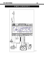
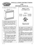
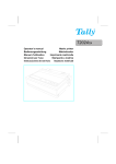
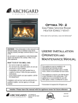
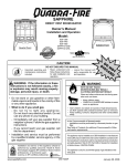
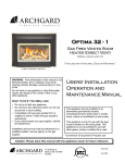
57-DVRS50 Gas Fired Vented Room Heater (Direct Vent) SERIAL NUMBERS 510000 AND HIGHER USERS’ INSTALLATION OPERATION and MAINTENANCE MANUAL WARNING: If the information in this manual is not followed exactly, a fire or explosion may result causing property damage, personal injury or loss of life. Do not store or use gasoline or other flammable vapors and liquids in the vicinity of this or any other appliance. This appliance may be installed in an aftermarket permanently located, manufactured home (USA only) or mobile home, where not prohibited by local codes. This appliance is only for use with the type of gas indicated on the rating plate. This appliance is not convertible for use with other gases, unless a certified kit is used. *Conversion kit required for Propane use WHAT TO DO IF YOU SMELL GAS: Do not try to light any appliance. Do not touch any electrical switch; do not use any phone in your building. Immediately call your gas supplier from a neighbor’s phone. Follow the gas supplier’s instructions. If you cannot reach your gas supplier, call the fire department. Installation and service must be performed by a qualified installer, service agency or the gas supplier. Tested and listed by INSTALLER: Leave this manual with the appliance. CONSUMER: Retain this manual for future reference. 7116 Beatty Dr Mission, BC V2V 6B4 Canada LABTEST Certification Inc Richmond, British Columbia ANSI Z21.88-2009/CSA 2.33-2009 200-0057 April 2013 INTRODUCTION Congratulations on choosing a Brigantia! The 57-DVRS50 is one of the most advanced Direct Vent Gas Fireplace heaters available today. It is solidly designed using the latest technology and manufactured to the highest quality. It is our aim to provide you with an appliance for many trouble-free years of reliable service. Some of the many features of your 57-DVRS50 are: Heater Classification The 57-DVRS50 is classified as a heating appliance. Therefore, it uses Direct Vent safety technology and it is suitable for continuously operated zone heating. High Efficiency The 57-DVRS50 has one of the highest efficiencies of any Direct Vent gas fireplace, which means that it is less expensive to operate. Adjustable Flame The flame aesthetics and heat output can be adjusted to suit the owner’s liking and heating needs. Solid Construction The 57-DVRS50 is mainly constructed of 16 and 18 gauge galvanized and aluminized coated steel for long life and durability. Optional Accessories Check with your Authorized Brigantia Dealer for optional accessories to suit your home’s décor and your tastes. Electronic Control System The 57-DVRS50 uses a gas control valve that is operated by a Multifunction Remote Control. It can be used as either an Intermittent Pilot or Standing Pilot system. Fireplace Model Number 57-DVRS50 Fireplace Serial Number Date of Installation Type of Gas Used by the Fireplace Dealer’s Name TABLE OF CONTENTS Caution and Safety Instructions 4 Appliance Certification, Installation Codes and Specifications 5 Rating Plate 6 Appliance Dimensions 7 Framing Dimensions and Clearance to Combustibles 8-9 Installation Instructions 10-12 Venting Instructions 13-18 Gas Connections 18 Panel & Baffle installation 19 Burner media, Door Surround Installation 20-21 Checking Inlet & Outlet pressures 22 Final Installation Check and Initial Operation 23 Lighting Instructions on Rating Plate 24 First Fire and Lighting Instructions (CAUTION) 25 Remote Control Setup and Operation 26-32 Conversion Kit Instructions 33-35 Maintenance and Cleaning the Appliance 36 Servicing Under Warranty 37 Wiring Schematics 38 Parts List 39 Frequently Asked Questions 40 Notes 41 Warranty 42 Warranty Registration Card 43 57-DVRS50 4 CAUTION & SAFETY FOR YOUR SAFETY - Do not install or operate your Brigantia 57-DVRS50 without reading and understanding this manual. Any installation or operational deviation from this instruction manual voids the Brigantia Industries Warranty and may prove hazardous. This appliance must be installed by a qualified gas installer and the installation must conform to the installation codes. Provide adequate clearance around air openings. Never obstruct front openings. Provide adequate clearances for proper operation and servicing of the appliance. This appliance must be properly connected to an approved venting system and must not be connected to a chimney flue serving a separate solid fuel burning appliance. Must provide adequate clearance around the intake and exhaust openings This appliance is equipped with a three pin plug for your protection against shock hazard and should be plugged directly into a properly grounded three prong receptacle. Do not cut or remove the grounding plug from this plug. Caution: Label all wires prior to disconnection when servicing controls. Wiring errors can cause improper and dangerous operation. Due to high temperatures, the appliance should be located out of traffic and away from furniture and draperies. Children and adults should be alerted to the hazards of high surface temperature and stay away to avoid burns or clothing ignition. Young children should be carefully supervised when they are in the same room as the appliance. Toddlers, young children and others may be susceptible to accidental contact burns. A physical barrier is recommended if there are at risk individuals in the house. To restrict access to a fireplace or stove, install an adjustable safety gate to keep toddlers, young children and other at risk individuals out of the room and away from hot surfaces. Clothing or other flammable material should not be placed on or near the appliance. Do not operate with cracked or broken glass. Be careful not to strike or slam the glass. Any safety screen or guard removed for servicing an appliance must be replaced prior to operating. Installation and Repair should be done by a qualified service person. The appliance should be inspected before use and at least annually by a professional service person. More frequent cleaning may be required due to excessive lint from carpeting, bedding materials, etc. It is imperative that the control compartments, burners and circulating air passageways of the appliance are kept clean. Do not use this appliance if any part has been under water. Immediately call a qualified service technician to inspect the appliance and to replace any part of the control system and any gas control which has been under water. 57-DVRS50 5 APPLIANCE CERTIFICATION This appliance was listed by LABTEST Certification Inc to the following USA and Canadian gas appliance standards. - ANSI Z21.88-2009/CSA 2.33-2009 Vented Gas Fireplace Heaters -CSA P.4.1-09 testing method for measuring annual fireplace efficiency. The listing label is attached to the appliance on the bottom right side of the appliance. A copy is shown on page Please contact Archgard Industries Ltd., if you have any questions regarding the certification of this appliance. INSTALLATION CODES This appliance must be installed by a qualified gas appliance installer. The installation must conform with the local codes or, in the absence of local codes, with the current National Fuel Gas Code ANSI Z223.1/ NFPA 54 in the US, or Installation Code CAN/CGA-B149.1 in Canada. Electrical connections and grounding must conform with local code, or current National Electrical code ANSI/NFPA No. 70-1987 in the US, and in Canada the current Canadian Electrical Code CSA C22.1. A manufactured home (USA only) or mobile home OEM installation must conform with the Manufactured Home Construction and Safety Standard, Title 24CFR, Part 3280, or, when such a standard is not applicable, the Standard for manufactured Home Installations, ANSI/NCSBCS A225.1 or Standard for Gas Equipped Recreational vehicles and Mobile Housing, CSA Z240.4 We recommend that our gas hearth products be installed and serviced by professionals who are certified in the U.S. by the National Fireplace Institute®(NFI) as NFI Gas Specialists. SPECIFICATIONS Maximum input rating / Entrée assignee Minimum input rating / Entrée assignee Maximum manifold pressure / Pression d’admission Minimum manifold pressure / Pression d’admission Orifice size - Center / Dimension de l’orifice Orifice size - Sides / Dimension de l’orifice Minimum supply pressure for purpose of input adjustment / Pression minimale d’alimentation pour le but d’adjustement de contribution Control Valve / La soupape controle Altitude / Elevation Electrical Rating / Tension electrique Primary Air opening Natural Gas LPG 50,000 BTU/hr (14.7kW) 21,000 BTU/hr (6.1 kW) 50,000 BTU/hr (14.7kW) 19,000 BTU/hr (5.6kW) 3.5” W.C. (0.9 kPa) 1.6” W.C. (0.4 kPa) 10” W.C. (2.5 kPa) 6” W.C. (1.5 kPa) #35 DMS (2.77mm) x 1 #48 DMS (1.93mm) x 2 #52 DMS (1.63mm) x 1 #57 DMS (1.09mm) x 2 5.0” W.C. (1.24kPa) 11.0” W.C. (2.8 kPa) SIT Proflame 885 SIT Proflame 885 0 - 2000ft (0 - 610m) 0 - 2000ft (0 - 610m) 120 VAC, 60 Hz, 1.4A 120 VAC, 60 Hz, 1.4A 1/16” (3mm) OPEN 1/4” (12mm) OPEN HIGH ALTITUDE INSTALLATION When installing this appliance beyond 2000 ft. (610 M) above sea level, the appliance must be properly de-rated and installed according to local codes, in the absence of local codes, with the current National Fuel Gas Code, ANSI Z223.1/ NFPA 54, in the US or Installation Code, CAN/ CGA-B149, in Canada. 57-DVRS50 Manifold pressure ( min - max)/ Pression d’ad6”W.C.(1.5kPa) - 10” W.C. (2.5 1.6”W.C.(.4 kPa) - 3.5”. W.C. (0.9 kPa) mission kPa) Orifice size-Center/ Dimension de l’orifice #35 DMS (2.77 mm dia.) x 1 #52 DMS (1.63 mm dia.) x 1 Orifice size-Sides/ Dimension de l’orifice #48 DMS (1.93 mm dia.) x 2 #57 DMS (1.09 mm dia.) x 2 Minimum supply pressure (for the purpose of input 5 in. W.C. (1.24 kPa) 11.0 in. W.C. (2.8 kPa) adjustment) / Pression minimale d’alimentation pour le but d’adustment de contribution Control valve / La soupape contrôle: SIT Proflame 885 SIT Proflame 885 Altitude / Elevation 0 - 2000 ft (0 - 610 m) 0 - 2000 ft (0 - 610 m) Electrical rating / Tension électrique 120 VAC, 60 Hz, 1.4 A 120 VAC, 0.6A Minimum Clearances to Combustibles / Distances: Keep burner and control compartment clean. Minimales entre l’appareil et les combustibles: See Instructions accompanying the heater. Maintenir propres le brûleur et le compartiment Ceiling / Plafond: 24” (609 mm) Measured from top of host shell de commande. Voir les instructions relatives à Floor / Plancher: 10” (152 mm) Measured from bottom of host shell l’installation et au fonctionnement qui accomAdjacent Side Wall/Paroi latérale adjacent: 18” (457 mm) pagnent le radiateur. 8” Deep Mantle : 12” (304 mm) Measured from top of host shell Adjacent sides and rear: 0” from stand-offs. Optional LP fuel conversion kit : 57-CKLP See Owner’s Manual for additional clearances Input rating (min/max)/ Entrée assignée LPG 19,000 - 50,000 BTU/hr (5.6 - 14.7kW) NG 21,000- 50,000 BTU/hr (6.1 - 14.7 kW) LISTED VENTED GAS FIREPLACE HEATER. RADIATEUR VENTILE, CIRCULATEUR DU TYPE VENTILATEUR. Tested to / Testée selon les normes : ANSI Z21.88-2009 / CSA 2.33-2009 VENTED GAS FIREPLACE HEATER-NOT FOR USE WITH SOLID FUEL. This vented gas fireplace heater is not for use with air filters. Certified for use in both CANADA and USA. / Certifié pour utilisation dans le Canada et les ÉTATS-UNIS MODEL / MODÈLE: 303-6057 APRIL Il faut que cet appareil soit installé selon les codes locaux, s’il y en a; sinon, suivre le CAN/CGA-B149 actuel au Canada et ANSI Z223.1 aux É.-U. Il faut que le raccordement électrique et la mise à la masse soient en conformité avec les codes locaux, s’il y en a; sinon, suivre le CAN/ CSA C22.1 actuel au Canada et ANSI/NFPA 70 aux É.-U. Cet appareil est certifié pour l’installation dans une chambre à coucher ou une pièce qui sert de chambre. This appliance must be installed in accordance with local codes, if any; if none, follow the National Fuel Gas Code, ANSI Z223.1/NFPA 54, or Natural Gas and Propane Installation Codes, CSA B149,1. Electrical connections and grounding must be in accordance with local codes, if any; if none, follow the current CAN/CSA C22.1 in Canada and ANSI/NFPA 70 in the US. This appliance is certified for installation in a bedroom or a bed sitting room. This appliance is only for use with the gas indicated on the rating plate and may be installed in an aftermarket, permanently located, manufactured (mobile) home where not prohibited by local codes. See owner’s manual for details. This appliance is not convertible with other gases, unless a certified kit is used. Made in Canada by / Fabrique au Canada par: Archgard Industries Ltd. LP / PROPANE NG / NATURAL NE PAS ENLEVER CETTE ÉTIQUETTE LC DO NOT REMOVE THIS LABEL # de série Serial # 57-DVRS50 6 RATING PLATE 57-DVRS50 APPLIANCE DIMENSIONS Surround Attached Surround Removed 7 57-DVRS50 8 Framing Dimensions The following section describes the requirements for framing for the model 57-DVRS50. Note: Framing should be constructed as required by local building codes 2 x 6 Framing, opening in framing should be minimum of 66.50”W x 42.00”H. Figure 1 Figure 2 57-DVRS50 9 Corner Install View Figure 3 Mantle Clearances 20” (504)mm 16” (403)mm Clearance to Combustibles 12” (304)mm Minimum measurements below are from the edge of door (unless otherwise noted). Measured from top of host shell. Figure 4 Inches MM Top - to standoffs 0” 0 Sides-to standoffs 0” 0 Adjacent Side Wall 18” 454 Room Floor* (From bottom of host shell) 5” 101 Vent - Top 2” 50 Vent - side/bottom 1” 25 Front 48” 1210 Room Ceiling (From top of host shell) 24” 907 * Clearance to combustible floor must maintain clearances from the top surface of carpet, flooring, etc. 57-DVRS50 10 Installation Instructions Figure 5 Stand-off 999-DV-8HTCL 57-DVRS50 11 Installation Instructions Frame opening and cut out hole for the termination and thimble as shown in fig. #6 Figure 6 When installing on an exterior wall you must install the exterior wall insulation board (#57-IB). Place insulation board with the foil facing into the room. Install the wall thimble (as shown below) and seal it and the edges of the insulation board with a good quality silicone sealant to prevent cold drafts. (exterior wall only) Se Figure 7 Nailing Flanges Figure 8 Figure 9 Install the nailing flanges provided, by screwing them to the side of the outer shell using the appropriate holes for the facing material. Place the fireplace into the framed opening and secure the nailing flanges to the wall. 57-DVRS50 Installation Instructions Cont. 12 Installed fireplace with stand-offs Figure 10 Figure 11 Caulk the outside portion of the vent collar to the fire-stop to prevent cold drafts. Next install the outer portion of the wall thimble and the termination. Figure 12 Note: For installations straight out the back of the 57-DVRS50 the Archgard 999-DV-8HTCL termination is required. The maximum horizontal run straight out the back is 6.00”(no rise). 57-DVRS50 13 Installation Instructions Cont. The following vent systems are certified for use with the model 57-DVRS50 Duravent 5 x 8 Direct Vent Selkirk 5 x 8 Direct Vent Ameri-vent 5 x 8 Direct Vent ICI 5 x 8 Direct Vent Archgard 999-DV-8HTCL (Through the wall termination) Note: ONLY THE LISTED VENT MANUFACTURERS LIST ABOVE MAY BE USED NOTE: Please refer to vent manufactures instructions regarding sealing methods and additional installation instructions as all vent manufactures use there own methods for sealing and general installation. VENTING Clearance to combustibles The following clearances must be maintained around the vent pipe: Vertical runs: 1” Horizontal runs: 2” on top, 1” sides and bottom IMPORTANT: This appliance venting system is a sealed system (DV), which means that all combustion air is supplied from outdoors and the combustion products are exhausted to the outdoors. Note: Only venting systems listed in this manual may be used with the model 57-DVRS50 Planning your vent installation This type of direct vent system may terminate in one of two ways: vertical termination using a vent cap, or horizontally using a wall termination. There are limitations to the vertical and/or horizontal lengths (see page 17 for venting chart). When calculating the length of the vent pipe from the outlet of the appliance to termination, allowing for ceiling thickness, the vertical rise in the attic or second story and sufficient vertical height above the roof. Fire stops are required at each floor level the vent passes through. 57-DVRS50 Installation Instructions Cont. LISTED VENTING SYSTEMS The listed chimney vent systems uses a twist lock connection. Assemble the vent system using the desired combination of sections and elbows for your installation. While assembling the vent pipe, ensure you bear in mind the aesthetic appearance if the venting is visible after installation. Keep seams oriented towards the wall or ceiling where possible. Make sure you fully insert and twist the mating sections all the way to make a solid connection. Figure 13 If for any reason the vent pipe is disconnected it must be correctly resealed 14 Horizontal Wall Vent Terminations The position of the horizontal vent termination must be positioned in such a way as to meet all local building codes. NOTE: ALLOWING THE VENT PIPE TO SLOPE DOWN TOWARDS THE VENT TERMINATION COULD CAUSE POOR COMBUSTION AND/OR HIGH TEMPERTURES THAT MAY PRESENT A FIRE HAZARD. Cut and frame the exterior wall to accept the Wall Thimble. Install the Wall Thimble shield using wood screws. If the wall being penetrated is constructed of non-combustible material concrete or block wall a 8” hole sufficient for the vent pipe is acceptable. To achieve the minimum vertical rise (6”), the Archgard 999-DV-8HTCL termination may be used. Do not install where vent may be blocked by snow or submerged in water. Ensure adequate space and drainage. Vent Restrictors Due to the extra flow produced by tall venting configurations the vent restrictors must be adjusted to maintain performance. The vent restrictor is designed into the appliance firebox. When required, adjust the restrictor inside the unit firebox. Release the screws and adjust the restrictor position according to the venting charts. Adjust restrictor as required using required hole position Venting terminals must not be recessed into wall or siding When the termination is to be attached to vinyl siding apply a bead of non-hardening mastic around the outside edge to form a seal between the standoff and the terminal. Attach the termination to the exterior wall using four wood screws through the holes in the corners. Complete the termination installation and apply a bead of mastic around the outer edge of the vinyl standoff. With the termination installed you can now connect the completed vent assembly by sliding the unit back towards the wall and carefully inserting the pipe into the terminal. Figure 14 Slide the pipe into the vent, making sure that at least 1¼” overlap between the pipe and the termination. 57-DVRS50 15 Installation Instructions Cont. Figure 22 – Vent Termination Locations Horizontal Installation G. The horizontal run must have a 1/4” rise on an exterior wall and must meet all local and national building codes, and must not be easily blocked or obstructed. Termination clearances are as follows (see Figure 16): Do not install above a meter/regulator assembly within 3 feet (90 cm) horizontally from the centerline of the meter/ regulator. Note: Clearances are to be in accordance with local installation codes and the requirements of the gas supplier. A. Clearance above ground, verandah, porch, deck, or bal- H. cony: 12” minimum (30 cm.) Clearance to a service regulator vent outlet: 6’ minimum (1.8 m) B. Clearance to a window or door that may be opened: 9” I. minimum (23 cm) Clearance to a non-mechanical air supply inlet to a building or the combustion air inlet to any other appliance: 12” minimum (30 cm) C. Vertical clearance to a ventilated soffit located above the termination within a horizontal distance of 2 feet from the J. centerline of the termination: 18” minimum (46 cm). Note: Clearances are to be in accordance with local installation codes and the requirements of the gas supplier. K. D. E. F. Clearance to an unventilated soffit: 18” minimum (45 cm). Note: Clearances are to be in accordance with local L. installation codes and the requirements of the gas supplier. Clearance to an outside corner: 12” (30 cm). Note: Clearances are to be in accordance with local installation M. codes and the requirements of the gas supplier. Clearance to an inside corner: 12” (30 cm). Note: Clearances are to be in accordance with local installation codes and the requirements of the gas supplier. Clearance to a mechanical air supply inlet: 6’ minimum (1.8 m) Clearance above paved sidewalk or paved driveway located on public property: refer to local code Clearance under open verandah, porch, deck, or balcony: 12” minimum (30 cm). Note: Clearances are to be in accordance with local installation codes and the requirements of the gas supplier. Maximum horizontal run 5’ after 2’ vertical rise. Liquid Propane gas 5’ horizontal run to 35’ vertical rise. Natural Gas maximum 35’ horizontal run with 7’ vertical rise. Note: Clearances are to be in accordance with local installation codes and the requirements of the gas supplier. 57-DVRS50 16 Installation Instructions Cont. Vertical Cap Installations Always maintain a 1” clearance around the vent pipe (vertical) and on horizontal venting 2” clearance on the top of the vent, when passing through ceilings, walls, roofs, enclosures, attic rafters or any combustible surfaces. DO NOT PACK AIR SPACES WITH INSULATION. Refer to the vent chart on page 17 for maximum allowable vertical and horizontal allowable installations. When planning your installation, determine if ceiling joists, roof rafters or other framing will obstruct the vent system. You may have to use 45° elbows to navigate around any obstacles. When passing through a flat ceiling, install a Box/Wall thimble. Cut a 10” square hole and frame as shown in the diagram opposite. Ensure all pipe sections are fully twist locked. NOTE: ALWAYS CHECK YOUR LOCAL CODES BEFORE INSTALLING VENTING. CLEARANCES, ETC, MAY VARY FROM STATE TO STATE(PROVINCE TO PROVINCE). Figure 15 Through Roof Framing Use a suitable round or square support through the roof as supplied by the vent manufacturer. 57-DVRS50 17 Installation Instructions Cont. Venting Chart Maximum Total Venting Length 40 Maximum total venting allowed is 50ft. This would be when configured for 40ft vertical with 10ft horizontal. Maximum vertical vent is 40ft. Maximum horizontal vent is 20ft. Minimum 10ft vertical vent rise required for maximum 20ft horizontal vent run. 35 V E R T I C A L V E N T R U N See chart for allowable vent runs. 30 Maximum horizontal elbows allowed - 3 Note: if more than 1 90˚ elbow is used horizontally the maximum horizontal is reduced by 1ft. 25 Example: If to reach the desired termination at point ‘A’ you use 2 90˚ elbows, you would be required to reduce the maximum horizontal from16’ to 15’. 20 If 3 90 ˚ elbows were used to reach point ’A’, the maximum horizontal would be reduced from 16’ to 14’. 15 10 A Restrictor Note: The model 57 DVRS50 is supplied with an adjustable restrictor. The restrictor is not required for most installs. However if the flame is considered too lively, the restrictor may be installed and adjusted to provide the required flame picture. Example: Using rigid pipe over 40’ may require restriction. 5 Figure 17 Figure 16 0 1 2 3 4 5 6 7 8 10 11 12 13 14 15 16 17 18 19 20 HORIZONTAL VENT RUN 57-DVRS50 18 GAS CONNECTIONS Before connecting the appliance to the gas supply line, double check that the appliance you have purchased is designed for the gas type you are using. The gas type markings are located on the certification label and also on the appliance’s gas valve. Adequate clearance for proper installation and checking of the gas connections must be provided. All gas connections must be checked for gas leaks. Have your gas supplier or a qualified gas fitter run a gas supply line into the fireplace. The line must be properly sized and fitted according to the installation codes. Immediately upstream of the supply connection, the fitter shall provide an accessible manual shut-off valve. When connecting the supply line to the gas valve, the installer shall brace the gas valve to ensure that the gas valve is not moved from its bracket. If the valve is not braced when the supply line is connected, the valve may be moved and cause a “break” in the main burner supply line. Such damage is not covered by the manufacturer’s warranty. CAUTION: The appliance must be isolated from the gas supply piping system by closing its individual manual shutoff valve during any pressure-testing of the gas supply piping system at test pressures equal to or less than 1/2 psig (3.5 kPa). Failure to do so will damage the appliance’s gas valve. Such damage is not covered by the manufacturer’s warranty. Natural Gas Pressure Settings: The inlet supply or line pressure must be a minimum of 5” W.C. (1.2 kPa) and a maximum of 14” W.C. (3.5 kPa). The orifices are a #35 DMS (2.73 mm) drill size for the center burner and #48 DMS (1.93 mm) for the two outer burners. ELEVATION INPUT RATING 0-2,000 ft (0-610 M) 50,000 BTU/hr (14.7 kW) 2,000 ft (610 M) and above. 50,000 BTU/hr (14.7 kW) less 4% per 1000 ft. (305 M) Please contact your local distributor for the appropriate orifice size you require. Propane Pressure Settings: The inlet supply or line pressure must be a minimum of 11” W.C. (2.8 kPa) and a maximum of 14” W.C. (3.5 kPa). The orifices are a #52 DMS (1.78 mm) drill size for the center burner and #57 DMS (1.07mm) for the two outer burners . ELEVATION INPUT RATING 0-2,000 ft. (0-610 M) 50,000 BTU/hr (14.7 kW) 2,000 ft. (610 M) and above. 50,000 BTU/hr (14.7 kW) less 4% per 1000 ft. (305 M) Please contact your local distributor for the appropriate orifice size you require. NOTE: THE INPUT RATING SHOULD ALWAYS BE CHECKED WHEN FIRST RUNNING THIS APPLIANCE. To do this, reduce the background flow rate, time the meter, light the fireplace and take another reading after 15 minutes of operation. Check with your gas supplier for the gas BTU content at your elevation. Input is the rate of flow multiplied by the heating value of the gas (cubic feet/hour x BTU per cubic feet). Adjust the manifold pressure so that the unit does not operate above the rated input. IMPORTANT: For high altitude installations above 2000 ft (610 meters), consult local gas distributor or the authority having jurisdiction for proper de-rating methods. 57-DVRS50 19 Rear Panel Installation Instructions 1. 2. Hang the left and right side back panel onto the bracket in the back of the firebox. Align with the far outside edge of the bracket. Hang the center back panel onto the bracket and slide the two outside panels in until they touch the center panel. Side Panel & Baffle Installation Instructions Set the right and left side panels by inserting the tabs into the slot of the support plate. Panel s should angle into the firebox (as shown) Set the baffle on top of the side panel so the slot in the baffle sets over the tab on the side panel. Small holes to the back The side panels are secured thru the side of the firebox 57-DVRS50 20 Glass Bead Installation BL AC KG Install the glass beads directly onto the burner so they are one layer deep and cover the entire burner pan. Do not use other media that is not approved by Archgard. LA SS Door Installation Install the top of the door so the slots in the door go over the tabs on the spring clips as shown to the right. Swing door down making sure it sits on top of the unit. CAUTION: Only doors certified with the appliance shall be used. Beware the glass does not drop out!! Pull the bottom spring clip out and over the tabs on the bottom of the door and release as shown below. NOTE: Do not remove any components while the appliance is hot. 57-DVRS50 21 Surround Clip Installation Install the four surround retaining clips so they are pushed back against the facing. Secure in place with the screws provided. See right Surround Installation The surround is held in place by clips buttons (two at the top, two at the bottom). Line up the clips with the fireplace and push until it locks in. You can adjust the surround by moving the brackets in and out on the fireplace NOTE: Do not remove any components while the appliance is hot. 57-DVRS50 22 CHECKING INLET AND OUTLET GAS PRESSURE 1. Remove the surround. 2. The pressure test taps are located on the valve. The taps are located in the gas valve front face. The inlet is marked ‘IN’ and the outlet is marked ‘OUT’. 3. Loosen the set screw inside the tap with a screwdriver. 4. Connect a 1/4” (6 mm) rubber tube to the tap post and a manometer. 5. Verify that the readings obtained are within specs (as shown on the appliance rating plate) 6. Be sure to tighten the set screw inside the tap after you have completed taking pressure readings. 7. Check for leaks. Outlet inlet Figure 19 Figure 18 The flame should not have yellow tips but should engulf the sensor. It can be adjusted by turning the screw marked “pilot” on the control valve. Figure 20 CHECKING AND ADJUSTING MAIN BURNER The main burner flame should be about 1/3 height of the viewing area and be strong without wispy or ghosting tips. 57-DVRS50 23 FINAL INSTALLATION CHECK Each Brigantia Gas Fireplace is checked and tested at the factory prior to being packaged and shipped to our dealers and finally installed in your home. Archgard recommends that before leaving this unit with the customer, the installer must ensure that the appliance is firing correctly and that the electrical system is in working order. This will include: 1. Perform leak tests of supply line, gas control valve, supply line from gas control valve and pilot assembly. 2. Clocking the appliance to ensure the correct firing rate (see page 5 of this manual). 3. If required, adjusting the primary air to burner to ensure that the flame does not carbon or soot. 4. Check for proper operation including correct drafting. As a reminder, a TAG is attached to all of our gas fireplaces. This TAG is located at the gas control valve. See Fig 21 Figure 21 ARCHGARD INDUSTRIES LTD. *** INSTALLER *** IMPORTANT NOTICE ALL GAS AND ELECTRICAL CONNECTIONS ** MUST ** BE CHECKED AND TESTED AT TIME OF INSTALLATION. Any alteration to the product that causes carboning or sooting that results in any damage or requires cleaning is not the responsibility of the manufacturer. INITIAL OPERATION 1. Check that the appliance is properly vented and connected to the gas supply. 2. Check that all external parts, such as door and faceplate are properly attached and fastened. 3. Do not operate this appliance with broken, cracked glass doors or without the door (s) in its correct (and latched) position. Do not abuse the glass by either striking or slamming shut. 4. Check that there are no fingerprints left on glass panels, as high temperature can bake these prints on permanently. 57-DVRS50 24 LIGHTING INSTRUCTIONS ON RATING PLATE FOR YOUR SAFETY READ BEFORE LIGHTING Pour votre sécurité Veuillez lire avant d'allumer WARNING: If you do not follow these instructions exactly, a fire of explosion may result causing property damage, personal injury or loss of life. ATTENTION: Si vous ne suivez pas ces instructions à la lettre, un feu d'une explosion entraînant des dommages matériels, des blessures ou la perte de la vie. A. This appliance has a pilot which must be lighted by a spark ignitor. When lighting the pilot follow these instructions exactly. B. BEFORE LIGHTING smell all around the appliance area for gas. Be sure to smell next to the floor because some gas is heavier than air and will settle on the floor. WHAT TO DO IF YOU SMELL GAS • Do not try to light any appliance. • Do not touch any electrical switch; do not use any phone in your building. • Immediately call your gas supplier from a neighbor’s phone. Follow the gas supplier’s instructions• If you cannot reach your gas supplier, call the fire department. C. Do not use this appliance if any part has been under water. Immediately call a qualified service technician to inspect the appliance and to replace any part of the control system and any gas control which has been under water. . A. Cet appareil possède une veilleuse qui doit être éclairée par une bougie d'allumage. En allumant le pilote suivez ces instructions à la lettre. B. AVANT D'ALLUMER odeur tout autour de l'appareil pour le gaz. Assurez-vous de sentir à côté du plancher, car certains gaz sont plus lourds que l'air et se déposent sur le sol. QUE FAIRE SI VOUS UNE ODEUR DE GAZ • Ne pas tenter d'allumer l'appareil. • Ne touchez à aucun interrupteur électrique; ne pas utiliser le téléphone dans votre immeuble. • Appelez immédiatement votre fournisseur de gaz de téléphone d'un voisin. Suivez les instructions du fournisseur de gaz • Si vous ne pouvez pas joindre votre fournisseur de gaz, appelez les pompiers. C. Ne pas utiliser cet appareil si une partie a été sous l'eau. Appeler immédiatement un technicien qualifié pour inspecter l'appareil et remplacer toute pièce du système de contrôle et de commande du gaz qui a été sous l'eau. LIGHTING INSTRUCTIONS INSTRUCTIONS D'ALLUMAGE STOP! Read the safety information above on this label. 1. This appliance is equipped with an ignition device which automatically lights the pilot. Do not try to light the pilot by hand 2. Set the remote switch to “OFF 3. Turn on the electric power to the appliance. STOP! Lire les consignes de sécurité ci-dessus sur cette étiquette. 1. Cet appareil est équipé d'un dispositif d'allumage qui allume automatiquement le pilote. Ne pas tenter d'allumer le pilote à la main 2. Réglez le commutateur à distance sur "OFF 3. Tournez sur la puissance électrique de l'appareil. 4. Ouvrez la vanne d'isolement de gaz 4. Open the Gas isolation valve 5. Tournez à distance à la position «ON» ". • Si le pilote et le brûleur ne reste pas allumée après serveral, • If the pilot and burner will not stay lit after serveral tries, turn the tourner la télécommande sur le "OFF" et vérifiez les instructions dans le manuel d'éclairage ou appelez votre technicien ou votre remote to the “OFF” and check the lighting instructions in the fournisseur de gaz. manual or call your service technician or gas supplier. 5. Turn remote to the “ON” position ”. TO TURN OFF GAS TO APPLIANCE INSTRUCTIONS D'ALLUMAGE 1. Set the remote switch to “OFF”. 2. Turn off all electric power to the appliance if service is to be performed. 3. Close the gas isolation valve 1. Réglez le commutateur à distance sur "OFF". 2. Coupez l'alimentation électrique de l'appareil si le service doit être exécuté. 3. Fermez la vanne d'isolement de gaz . 303-6001 16 JAN 2010 57-DVRS50 25 FIRST FIRE When operated for the first few times, the appliance will emit some odor and fumes. This is due to the heat from the appliance evaporating the oils and solvents used in fabricating the appliance. Close off the room to the rest of the house and open all windows. Keep the room well ventilated, as smoke alarm may sound. Run the appliance for at least 6 hours at maximum setting to allow paint to cure. Smoke and fumes caused by the curing process may cause discomfort to some individuals. LIGHTING INSTRUCTIONS - CAUTION WARNING : If you do not follow these instructions exactly, a fire or explosion may result causing property damage, personal injury or loss of life. Do not operate the appliance with the glass front removed, cracked or broken. Replacement of broken glass should be done by a licensed or qualified service person. WARNING : This appliance needs fresh air for safe operation and must be installed so there are provisions for adequate combustion and ventilation air. : use Thisgasoline appliance needs fresh air vapors for safeand operation DoWARNING not store or or other flammable liquids inand the must vicinitybeofinstalled this or any other appliance.so there are provisions for adequate combustion and ventilation air. WHAT TO DO IF YOU SMELL GAS: Do not try to light any appliance. Do not touch any electrical switch; do not use any phone in your building. Immediately call your gas supplier from a neighbor’s phone. Follow the gas supplier’s instructions. If you cannot reach your gas supplier, call the fire department. Installation and service must be performed by a qualified installer, service agency or the gas supplier. 1. 2. 3. 4. BEFORE LIGHTING, smell all around the appliance area for gas. Be sure to smell next to the floor, because some gasses are heavier than air and will settle on the floor. IF YOU SMELL GAS, follow the instructions as listed directly above or as shown on the front cover of this manual. Do not use this appliance if any part has been under water. Immediately call a qualified service technician to inspect the appliance and to replace any part of the control system and any gas control which has been under water. This appliance is equipped with an ignition device which automatically lights the pilot and main burner. The pilot and burner light automatically with the hand held remote or with the switch on the side of the surround if it is activated. 57-DVRS50 26 REMOTE CONTROL SETUP AND OPERATION (future option) 57-DVRS50 27 REMOTE CONTROL SETUP AND OPERATION, cont. * N.A. on this unit * Future Option 57-DVRS50 REMOTE CONTROL SETUP AND OPERATION, cont. 28 57-DVRS50 REMOTE CONTROL SETUP AND OPERATION, cont. 29 57-DVRS50 REMOTE CONTROL SETUP AND OPERATION, cont. 30 57-DVRS50 31 REMOTE CONTROL SETUP AND OPERATION, cont. The unit is shipped from the factory with the ability for IPI/CPI selection active. To disable the Continuous Pilot selection ability, cut one of the wires (blue or white) shown in the picture and cap. 57-DVRS50 REMOTE CONTROL SETUP AND OPERATION, cont. 32 57-DVRS50 33 CONVERSION KIT INSTRUCTIONS IMPORTANT: This fireplace is Natural gas ready. If converting to LP gas, follow instructions below KIT NUMBER: 57-CKNG for NAT GAS KIT NUMBER: 57-CKLP for LPG Step # 1 - PREPARATION Remove outer surround and door. Place to the side to prevent them from being damaged. Step # 2 - PREPARATION Remove the angled side panels and upper baffle. Remove side panel support plates on each side of the fireplace Step #3 - BURNER REMOVAL Remove the burner media. Remove burners by loosening and removing the wing nuts from underneath The outer burners are removed by sliding towards the outside of the firebox and lifting out. The center burner slides to the left and lifts out. Step #4 - ORIFICE CHANGE This fireplace uses three orifices. The two (2) outside burner orifices (#57DMS propane) and the center burner orifice (#52DMS propane) Care must be taken not to install the center orifice in an outside burner position. This will result in an unstable burn pattern that may cause venting and soot problems. Using a 1/2” wrench remove and replace the existing orifices one at a time. This will help prevent errors with the new orifice installation. Step #5 - PILOT CONVERSION Using a 7/16” wrench and loosen the pilot hood 1/4 turn. Slide the tab at the bottom of the orifice hood all the way so the red side (propane) with the hole in it is showing. Tighten the pilot hood back up so that it is lined up with the two probes on both sides of the pilot assembly. Figure 22 LP has hole and red dot Natural Gas Figure 23 WARNING: SHUT OFF GAS SUPPLY AND ELECTRICAL POWER TO FIREPLACE SHUT OFF GAS SUPPLY BEFORE DISCONNECTING ELECTRICAL POWER 57-DVRS50 CONVERSION KIT INSTRUCTIONS, con’t Step # 7 Valve Conversion 34 57-DVRS50 35 CONVERSION KIT INSTRUCTIONS, con’t Step # 8 Complete the Conversion Fill out and attach conversion label to the fireplace near the valve Change Rating Plate to show new fuel configuration Reinstall the burners, support plates and baffle by reversing the removal process. Turn on the gas and electrical supplies. Check for leaks using approved means Confirm correct incoming and manifold pressures Test fire the fireplace to confirm correct operation. Reinstall door assembly and surround Run through a complete firing cycle to confirm correct operation Figure 24 KIT NUMBERS: “57-CKLP” for LP gas and “57-CKNG” for Natural Gas KIT INCLUDES: 1- Gas conversion label (303-0128) 1- Center burner orifice (#52 DMS for LPG) (#35 DMS for Natural Gas) 2 - Side burner orifices (#57 DMS for LPG) (#48 DMS for Natural Gas) 1- Instruction Sheet 1- SIT 885 Valve conversion kit c/w instructions & gas type label (0.907.012 IMPORTANT: For high altitude installations above 2000 ft (610 meters), consult local gas distributor or the authority having jurisdiction for proper de-rating methods. 57-DVRS50 36 MAINTENANCE CAUTION: Do not conduct maintenance on the appliance while it is operating or while it is still hot. CLEANING THE APPLIANCE The exterior painted surfaces, glass and plated trims may be cleaned with a soft, non-abrasive cloth and water or a suitable, mild, non-abrasive cleaner. Regularly: Frequent cleaning of the ceramic glass is required. Archgard recommends using a good quality “gas fireplace” glass cleaner that is available at any hearth retail location. DO NOT CLEAN WHILE HOT. Clean and remove any lint accumulations or debris from the grills and in any combustion and convection air passage ways. Keep the appliance area free from combustible materials, such as paper, wood, clothing, gasoline and flammable solids, liquids and vapors. Visually check the height and color of the burner and pilot flames. Every 2 to 3 months: Remove the glass door and clean the inside of the glass with a good quality “gas fireplace” glass cleaner. DO NOT CLEAN WHILE HOT. Once a year, have a qualified service technician: Completely inspect the appliance and the venting system, if the vent pipe or seal is found to be defective, replace and or reseal Clean and remove any lint accumulations or debris in the firebox, on the burners, on the pilot, at the primary air opening, and in any combustion and convection air passageways. Check the safety system of the gas valve and the appliance. WARNING: All parts removed or disturbed, including guards and grills, must be properly replaced after maintenance. Service and repair must be conducted by a qualified service person. If these instructions are not followed, a fire or explosion may result, causing property damage, personal injury or loss of life. 57-DVRS50 37 SERVICING UNDER WARRANTY Before servicing, read the terms and conditions of the Brigantia warranty at the back of the manual. Contact the authorized Brigantia dealer where you purchased the appliance from and provide them with details of the problem, along with the initial installation information (from the front of this manual). WARNING: Servicing of this appliance must be conducted by a qualified service technician. Improper servicing, adjustment or alteration of this appliance may cause property damage, personal injury or loss of life. All servicing should be conducted with the appliance cold. All replacement parts must be authorized by Archgard Industries for suitability. 57-DVRS50 38 WIRING SCHEMATICS Figure 25 57-DVRS50 39 PARTS LIST Item # Item Description Unit 308-6011 SIT PROFLAME II CONTROL MODULE Main control module 308-6012 WIRING HARNESS Main wiring for module 308-6016 WIRING HARNESS SPLIT FLOW Split flow wiring harness 308-6013 BATTERY HOLDER AA Battery holder 308-6014 HANDHELD REMOTE - PROFLAME II Handheld remote control 308-6017 SIT 885 VALVE W/STEP MOTOR Main gas valve 308-6015 SPLIT FLOW VALVE (3/8" NPT) Valve for outside burners 308-6019 PSE SPARK PILOT ASSEMBLY PSE pilot assembly 857-0050-C CENTER PAN BURNER Burner 857-0050-L LEFT SIDE PAN BURNER Burner 857-0050-R RIGHT SIDE PAN BURNER Burner BURNER GLASS MEDIA - JET BLACK Glass bead media DOOR ASSEMBLY ** (BLACK) Door frame, glass & gasket INTEGRITY SPRING Relief spring for door system 57-FBJB 57-DB 300-0134 ** The door shall only be replaced as a complete unit as supplied by the manufacturer. Do not abuse glass doors by striking or slamming shut. Do not operate with broken glass. Substitute materials shall not be used. Optional fuel conversion kit : 57-CKLP LP Conversion (instructions supplied in kit) 57-CKNG NG Conversion (instructions supplied in kit) 57-DVRS50 40 FREQUENTLY ASKED QUESTIONS Listed below are some frequently asked questions regarding Brigantia Gas Fireplaces. If you have questions that are not listed below, or are not answered in this manual, please contact your Authorized Brigantia Dealer. Q. My glass has a condensation “fog” when the appliance is first lit. A. Condensation is normal and will disappear in a few minutes after the glass is heated. Q. I have a white “film” on my glass. What is the best way to clean the inside of the glass. A. Frequent cleaning of your glass is recommended. Archgard recommends using a good quality “gas fireplace” glass cleaner that is available at all authorized dealers. Do not use abrasive materials, and do not clean the glass or the appliance when the unit is hot. Q. How do I care for my plated trims. A. Clean with a damp cloth. DO NOT use chemical cleaners as they may harm the finish, and void your warranty. NOTE: If the top louvers, or top overlay starts to discolor, check the door gasket seal and replace if necessary. Q. I hear a “ticking”, “cracking” or “pinging” sound when my fireplace is running, and after it is turned off. A. The different gauges of steel used to manufacture your fireplace will expand and contract at different rates when your fireplace is on, and will continued as your fireplace completes its heating function. You will likely hear these same sounds more on start up and shut down. This is normal for steel fireplaces. Q. When my appliance is OFF and my pilot light is lit, I hear a “whisper” sound. A. The lit pilot can make a small noise. Sometimes in extreme wind conditions you may be able to hear air entering into the firebox chamber. Q. I hear a “click" when my main burner turns ON or OFF. A. Your Gas Control Valve will make a clicking sound when it opens to allow gas to flow to the main burner. This is a normal part of the operating system. Q. Can I burn wood and other materials in my gas fireplace. A. No! Burning anything other than natural or LP gas in a gas fireplace or stove will create a potential fire hazard and present a danger to your home and its occupants. Only burn the gas fuel for which the unit was originally designed. Q. Can I shut my pilot off in the summer? A. You will save energy by turning off the pilot light if you are not using your appliance for the hot summer months. Remember to relight it before you want to use the appliance for the first time in the fall. Refer to your owners manual for lighting instructions. 57-DVRS50 NOTES 41 57-DVRS50 42 BRIGANTIA LIMITED WARRANTY This Limited Warranty is made by Archgard Industries, hereinafter referred to as “Brigantia”. Brigantia warrants to the original purchaser of a Brigantia gas burning fireplace (s) that the product will be free of defects in materials and workmanship under normal use and service, for a “lifetime”. INCLUSIONS: “LIFETIME LIMITED WARRANTY“ ( to original purchaser) ❖ All heat exchangers, combustion chamber, burner tubes and pans. ❖ Ceramic Panels against splitting or cracking from heat exposure. ❖ Ceramic Glass against thermal breakage (i.e.: flaking) ❖ NOTE: Discoloration and some minor movement of certain parts are normal and are not a defect and therefore, not covered under warranty. The above will be covered “parts & labor” to the original purchaser for FIVE years and “parts” only thereafter from original date of purchase. INCLUSIONS: “FIVE YEAR LIMITED WARRANTY” ❖ Five year limited warranty on the Burner System. Warranty will cover any defective burner if defect is deemed as original by the manufacturer. The above will be covered “parts & labor” to the original purchaser for TWO years and “parts” only thereafter from original date of purchase. INCLUSIONS: “ONE YEAR LIMITED WARRANTY” All plated trims and accessories against tarnishing. All trim accessories against tarnishing and paint defects. Rocker switches and wiring. Gas control valves, pilot assemblies including electrodes, and igniters. The above will be covered “parts & labor” to the original purchaser for ONE year from date of purchase. ❖ ❖ ❖ ❖ EXCLUSIONS: ❖ Ember material. ❖ Travel time or mileage to original purchasers residence. Archgard suggests that you pre-arrange travel expenses with your Authorized Brigantia Dealer. WHAT TO DO IN THE EVENT OF A PROBLEM: ❖ Thoroughly read your manual. ❖ If you cannot solve the problem, contact your Brigantia Dealer or representative. ❖ When calling for help please have the following information: Model of your Fireplace Serial Number Place of Purchase Date of Purchase Problem Description ❖ NOTE: Warranty may be void if work is carried out by an unqualified person (s). Only original Brigantia parts may be used. Please consult your Brigantia dealer or representative if in doubt about a replacement part (s). OBTAINING WARRANTY SERVICE: To obtain warranty service, the original purchaser shall return the defective part (s) to the original authorized Brigantia selling dealer transportation prepaid, along with the serial number of the appliance and proof of purchase. Any defective part, in our judgment, will be repaired or replaced at Archgard's discretion. The dealer must obtain approval from Brigantia before any repairs are made. WARRANTY LIMITATION: THIS LIMITED WARRANTY IS MADE IN LIEU OF ALL OTHER WARRANTIES, EXPRESSED OR IMPLIED AS TO QUALITY, MERCHANTABILITY OR FITNESS FOR PARTICULAR PURPOSE. The appliance is only warranted for the use as intended by the installation and operating instruction and local building codes. The warranty will not cover damage due to accident, misuse, abuse, alteration, improper installation or “Acts Of God”. This limited warranty is void unless the appliance is installed by a qualified installer, in accordance with the instructions furnished with the appliance. Some Provinces or States do not allow limitations on how long an implied warranty lasts, so the above limitation may not apply to the original purchaser. Any damage resulting from defects in this product, is limited to the replacement of the defective part (s) and does not include incidental and consequential exposures sustained in connection with the product. This includes facing (s), mantle (s), cabinet (s), tile (s) or any other finishes resulting from removal of any gas appliance. This warranty is limited to residential use only and gives the consumer specific rights. These rights may vary from State to State or Province to Province. POSTAGE CUT ALONG LINE WARRANTY REGISTRATION ARCHGARD INDUSTRIES 7116 BEATTY DRIVE MISSION, B.C. CANADA V2V 6B4 CUT ALONG LINE FOLD DOWN AT LINE FOLD DOWN AT LINE & TAPE CLOSED Model # : 57-DVRS50 Serial #: Date Installed: / mm Name: Address: CUT ALONG LINE City: State/Prov: ZIP: Phone: ( _____ ) State/Prov: ZIP: Phone: ( _____ ) State/Prov: ZIP: Phone: ( _____ ) Dealer's Name & Address: City: Installer's Name & Address: City: Why did you choose this product? Thank you for purchasing our product and filling out this warranty card. / did yyyy ARCHGARD INDUSTRIES 7116 Beatty Drive Mission, B.C. V2V 6B4 Canada Website: www.archgard.com