1
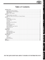
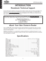
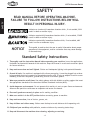
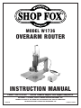
MODEL W1736
OVERARM ROUTER
INSTRUCTION MANUAL
Phone: 1-360-734-3482 • On-Line Technical Support: [email protected]
COPYRIGHT © OCTOBER, 2004 BY WOODSTOCK INTERNATIONAL, INC.
#6617TR
WARNING: NO PORTION OF THIS MANUAL MAY BE REPRODUCED IN ANY SHAPE OR FORM WITHOUT
THE WRITTEN APPROVAL OF WOODSTOCK INTERNATIONAL, INC.
Printed in Taiwan
WARNING
Some dust created by power sanding, sawing, grinding, drilling, and other construction activities contains chemicals known to the State of California to
cause cancer, birth defects or other reproductive
harm. Some examples of these chemicals are:
• Lead from lead-based paints.
• Crystalline silica from bricks, cement, and
other masonry products.
• Arsenic and chromium from chemically
treated lumber.
Your risk from these exposures varies, depending on
how often you do this type of work. To reduce your
exposure to these chemicals: work in a well ventilated area, and work with approved safety equipment, such as those dust masks that are specially
designed to filter out microscopic particles.
SAFETY
SET UP
OPERATIONS
MAINTENANCE
INTRODUCTION ..................................................................................................2
Woodstock Technical Support ............................................................................ 2
About Your New Overarm Router ........................................................................ 2
Specifications ............................................................................................... 2
Controls and Features ..................................................................................... 3
SAFETY............................................................................................................4
Standard Safety Instructions ............................................................................. 4
Additional Safety Instructions for Overarm Routers .................................................. 6
SET UP ............................................................................................................7
Unpacking ................................................................................................... 7
Items Needed for Set Up .................................................................................. 7
Cleaning Parts .............................................................................................. 7
Inventory .................................................................................................... 8
Assembling Overarm Router .............................................................................. 9
Mounting ....................................................................................................10
Attaching Foot Switch ....................................................................................11
Installing Router ...........................................................................................12
Aligning Router with Table Pin .........................................................................13
Connecting to Air .........................................................................................14
Test Run ....................................................................................................14
OPERATIONS ................................................................................................... 15
General .....................................................................................................15
Adjusting Valves ...........................................................................................15
Adjusting Plunge Depth ..................................................................................16
Using Table Pins ...........................................................................................17
MAINTENANCE ................................................................................................. 18
General .....................................................................................................18
Table ........................................................................................................18
Lubrication .................................................................................................18
Troubleshooting ...........................................................................................19
PARTS ........................................................................................................... 20
WARRANTY ..................................................................................................... 22
INTRODUCTION
Table of Contents
PARTS
WARRANTY
USE THE QUICK GUIDE PAGE LABELS TO SEARCH OUT INFORMATION FAST!
INTRODUCTION
W1736 Overarm Router
INTRODUCTION
Woodstock Technical Support
We stand behind our machines! In the event that a defect is found, parts are missing or questions arise
about your machine, please contact Woodstock International Technical Support at 1-360-734-3482 or
send e-mail to: [email protected]. Our knowledgeable staff will help you troubleshoot problems, send out parts or arrange warranty returns.
If you need the latest edition of this manual, you can download it from http://www.shopfox.biz.
If you still have questions after reading the latest manual, or if you have comments please contact us at:
Woodstock International, Inc.
Attn: Technical Support Department
P.O. Box 2309
Bellingham, WA 98227
About Your New Overarm Router
Your new SHOP FOX® Overarm Router has been specially designed to provide many years of troublefree service. Close attention to detail, ruggedly built parts and a rigid quality control program assure
safe and reliable operation.
Woodstock International, Inc. is committed to customer satisfaction in providing this manual. It is our
intent to make sure all the information necessary for safety, ease of assembly, practical use and durability of this product be included.
Specifications
Table ................................................................. 19-3/4" W x 14" D x 1-3/8" Thick
Overall Height .................................................................................... 31-3/8"
Overall Width ..................................................................................... 21-3/4"
Overall Depth ..................................................................................... 28-1/4"
Footprint ......................................................................... 21-3/4" W x 28-1/4" D
Machine Weight.................................................................................... 56 lbs
Maximum Head Stroke ............................................................................5-1/2"
Maximum Distance Spindle to Table.............................................................6-1/2"
Maximum Distance Housing to Table ........................................................... 8-3/4"
Throat Capacity ....................................................................................... 18"
Router Adapter Sizes ......................................................... 3.25", 3.328", 3.5", 4.2"
Router Housing Size................................................................................4-1/2"
Table Pins (3) ................................................ 3/16" x 1/4", 5/16" x 3/8", 7/16" x 1/2"
Table Construction ..............................................................Milled Cast Aluminum
Body Construction ......................................................................Cast Aluminum
Clamp Housing ...........................................................................Cast Aluminum
Required Operating Air Pressure ................................................................ 60 PSI
Maximum Air Pressure ........................................................................... 115 PSI
-2-
INTRODUCTION
W1736 Overarm Router
Controls and Features
A
B
F
C
D
G
E
A. Top Valve: Controls the speed that the router
rises from the plunge (down) position.
B.
Bottom Valve: Controls the plunge speed of the
router.
C. Head: The part of the overarm assembly that
houses the router motor and moves up and
down when activated by the foot pedal.
D. Pin Adjustment Knob: Locks the table pin in
place for pin routing operations.
E.
Foot Switch: When connected to air, controls
the up and down motion of the head.
F.
Router Motor Adapters: Allows various sizes
and brands of router motors to be installed on
the overarm assembly.
G. Plunge Depth Knob: Adjusts the plunging depth
of the head.
-3-
W1736 Overarm Router
SAFETY
SAFETY
READ MANUAL BEFORE OPERATING MACHINE.
FAILURE TO FOLLOW INSTRUCTIONS BELOW WILL
RESULT IN PERSONAL INJURY.
Indicates an imminently hazardous situation which, if not avoided, WILL
result in death or serious injury.
Indicates a potentially hazardous situation which, if not avoided, COULD
result in death or serious injury.
Indicates a potentially hazardous situation which, if not avoided, MAY
result in minor or moderate injury.
NOTICE
This symbol is used to alert the user to useful information about proper
operation of the equipment, and/or a situation that may cause damage
to the machinery.
Standard Safety Instructions
1. Thoroughly read the Instruction Manual before operating your machine. Learn the applications,
limitations and potential hazards of this machine. Keep the manual in a safe and convenient place
for future reference.
2. Keep work area clean and well lighted. Clutter and inadequate lighting invite potential hazards.
3. Ground all tools. If a machine is equipped with a three-prong plug, it must be plugged into a threehole grounded electrical receptacle or grounded extension cord. If using an adapter to aid in accommodating a two-hole receptacle, ground using a screw to a known ground.
4. Wear eye protection at all times. Use safety glasses with side shields or safety goggles that meet
the appropriate standards of the American National Standards Institute (ANSI).
5. Avoid dangerous environments. Do not operate this machine in wet or open flame environments.
Airborne dust particles could cause an explosion and severe fire hazard.
6. Ensure all guards are securely in place and in working condition.
7. Make sure switch is in the OFF position before connecting power to machine.
8. Keep work area clean, free of clutter, grease, etc.
9. Keep children and visitors away. Visitors must be kept at a safe distance while operating unit.
10. Childproof your workshop with padlocks, master switches or by removing starter keys.
11. Stop and disconnect the machine when cleaning, adjusting or servicing.
-4-
W1736 Overarm Router
12. Do not force tool. The machine will do a safer and better job at the rate for which it was
designed.
13. Use correct tool. Do not force machine or attachment to do a job for which it was not designed.
15. Remove adjusting keys, rags, and tools. Before turning the machine on, make it a habit to check
that all adjusting keys and wrenches have been removed.
16. Avoid using an extension cord. But if you must use one, examine the extension cord to ensure it
is in good condition. Immediately replace a damaged extension cord. Always use an extension cord
that uses a ground pin and connected ground wire. Use an extension cord that meets the amp rating
on the motor nameplate. If the motor is dual voltage, be sure to use the amp rating for the voltage
you will be using. If you use an extension cord with an undersized gauge or one that is too long,
excessive heat will be generated within the circuit, increasing the chance of a fire or damage to the
circuit.
17. Keep proper footing and balance at all times.
18. Lock the mobile base from moving before feeding the workpiece into the machine.
19. Do not leave machine unattended. Wait until it comes to a complete stop before leaving the
area.
20. Perform machine maintenance and care. Follow lubrication and accessory attachment instructions
in the manual.
21. Keep machine away from open flame. Operating machines near pilot lights or open flames creates
a high risk if dust is dispersed in the area. Dust particles and an ignition source may cause an explosion. Do not operate the machine in high-risk areas, including but not limited to, those mentioned
above.
22. If at any time you are experiencing difficulties performing the intended operation, stop using the
machine! Then contact our technical support or ask a qualified expert how the operation should be
performed.
23. Habits—good and bad—are hard to break. Develop good habits in your shop and safety will become
second-nature to you.
24. Be aware that certain woods may cause an allergic reaction in people and animals, especially
when exposed to fine dust. Make sure you know what type of wood dust you will be exposed to and
the possibility of an allergic reaction.
-5-
SAFETY
14. Wear proper apparel. Do not wear loose clothing, neck ties, gloves, jewelry, and secure long hair
away from moving parts.
W1736 Overarm Router
Additional Safety Instructions for Overarm Routers
SAFETY
READ and understand this
entire instruction manual
before using this machine.
Serious personal injury
may occur if safety and
operational information is
not understood and followed. DO NOT risk your
safety by not reading!
USE this and other machinery with caution
and respect. Always consider safety first,
as it applies to your individual working
conditions. No list of safety guidelines can
be complete—every shop environment is
different. Failure to follow guidelines could
result in serious personal injury, damage
to equipment or poor work results.
1.
READ THE ROUTER MANUAL. Read and understand the instruction manual that was included with
the router you intend to install. If you do not understand the safety and operation instructions for
your router, do not install it on the Model W1736.
2.
ROUTER INSTALLATION. Make sure the installed router is tightly secured in the housing before
turning it ON.
3.
PLUNGE DEPTH. Always check the plunge depth with the router turned OFF to make sure that an
installed router bit will not contact the table when the foot switch is pressed and the router is
running.
4.
GUARDS. Make sure all guards are in place during operation. If you remove them for cleaning,
replace them immediately. If guards become cracked, replace them immediately before operating
the Model W1736 again.
5.
AVOIDING CONTACT WITH ROUTER BIT.
• Never place your hand under the router while the router is ON or when plunging the router.
• Never attempt a routing operation that will bring any part of your hand/fingers within 12" of
the spinning router bit.
• If the workpiece is too small, build a clamping jig to hold in place, or use a longer workpiece
and cut to size after routing.
• Use the table pin. The table pin guides the workpiece in a predictable manner and greatly
increases operator control in the event of a kickback or climb cut.
6.
PATTERN ROUTING. Test all patterns with the table pin to make sure that the pattern template
works before attempting to rout your workpiece.
-6-
W1736 Overarm Router
SET UP
Unpacking
The SHOP FOX® Model W1736 has been carefully packaged for safe transporting. If you notice the machine has
been damaged, please contact Woodstock International
Technical Support at 1-360-734-3482 or send e-mail to:
[email protected]
Items Needed for Set Up
•
•
•
•
•
•
•
•
•
Air Compressor .............................................1
Air Hose with 3/8" Female Quick Connect Fitting ...1
Hex Wrench 6mm..........................................1
Hex Wrench 8mm..........................................1
Phillips Screwdriver .......................................1
Open-End Wrench 12mm .................................1
Open-End Wrench 17mm .................................1
Router w/Removable Base ...............................1
Mounting Hardware Specific to Application .... Varies
Cleaning Parts
The table and other unpainted parts of your overarm
router are coated with a waxy grease that protects them
from corrosion during shipment.
Clean this grease off with a solvent cleaner or citrusbased degreaser. DO NOT use chlorine-based solvents
such as brake parts cleaner or acetone—if you happen to
splash some onto a painted surface, you will ruin the finish.
-7-
READ and understand this entire instruction manual before using this machine.
Serious personal injury may occur if
safety and operational information is not
understood and followed. DO NOT risk
your safety by not reading!
MAKE your shop “child
safe.” Ensure that your
workplace is inaccessible
to youngsters by closing
and locking all entrances
when you are away. NEVER
allow untrained visitors in
your shop when assembling, adjusting or operating equipment.
SET UP
The following items are needed, but not included, to
setup your machine:
W1736 Overarm Router
Inventory
SET UP
The following is a description of the inventory of the
components shipped with the SHOP FOX® Model
W1736. Lay the components out and inventory your shipment.
SUFFOCATION
HAZARD!
Immediately discard
all plastic bags and
packing materials to
eliminate choking/suffocation hazards for
children and animals.
Main Inventory Components (Figure 1)
A. Table ........................................................1
B. Support Arm ................................................1
C. Router Adapters ..........................................4
• 3.25" (fits many Makita)
• 3.328" (fits many Milwaukee)
• 3.5" (fits many Bosch, Porter-Cable, & Makita)
• 4.2" (fits many Porter-Cable)
D. Head Assembly .............................................1
E. Foot Switch Assembly .....................................1
F. Router Safety Guard ......................................1
G. Front Guard ................................................1
H. Side Guard ..................................................1
Part and Fastener Hardware (Figure 2)
I. Table Pin Knob Bolt .......................................1
J. Rubber Gasket .............................................1
K. Table Pins...................................................3
L. Rubber Washer 11mm ....................................1
M. Round Adjustment Nuts M10-1.5 ........................2
N. Hardware Bag ..............................................1
• Cap Screws M10-1.5 x 45 ..............................4
• Cap Screws M10-1.5 x 25 ..............................4
• Lock Washers 10mm ....................................8
• Flat Head Screws M5-.8 x 10 ..........................4
• Lock Nut M10-1.5 .......................................1
• Thumbscrews M5-.8 x 10 ..............................2
• Plastic Washers 5mm ...................................2
• Flange Screw M4-.7 x 12...............................1
O. Cord Loop 5/8" .............................................1
P. Shaft Screw .................................................1
If any parts appear to be missing, examine the packaging carefully to be sure those parts are not among the
packing materials. If any parts cannot be found, find
the part number in the back of this manual and contact
Woodstock International, Inc. at 360-734-3482 or at
[email protected]
NOTICE
When ordering replacement parts, refer to the parts
list and diagram in the back of the manual.
-8-
A
B
C
D
F
E
G
H
Figure 1. Main inventory components.
I
K
J
L
M
N
O
P
Figure 2. Part and fastener hardware.
W1736 Overarm Router
Assembling Overarm
Router
1.
Using four M10-1.5 x 45 cap screws and lock washers, attach the support arm to the table with the
rubber gasket in the middle (see Figure 3).
2.
Mount the head assembly to the support arm with
four M10-1.5 x 25 cap screws and lock washers (see
Figure 3), and tighten evenly.
3.
Attach the side guard to the head assembly with two
flat head screws (see Figure 3).
5.
6.
Thread the round adjustment nuts onto the shaft,
and slide the rubber washer over the shaft and up
against the round adjustment nuts.
Insert the shaft into the head assembly and tighten
the lock nut onto the end of the shaft (see Figure
4).
Install the front guard with two flat head screws,
taking care not to break the guard by overtightening
(see Figure 5).
7.
Install the router safety guard with the two thumbscrews and plastic washers, taking care not to break
the guard by overtightening (see Figure 5).
8.
Thread the table pin knob bolt into the front of the
table (see Figure 5). (It may help to lift the table
so you can see where the shaft needs to thread into
the table.)
9.
Head to
Support Arm
Rubber
Gasket
Support Arm
to Table
Figure 3. Initial assembly of support arm,
head assembly, and side guard.
Shaft
Round Nuts
Rubber Washer
Lock Nut
Figure 4. Shaft, round nuts, rubber
washer, and lock nut installed.
Install the cord loop with the M4-.7 x 12 flange
screw (see Figure 5).
Front Guard
Table
Pin Knob
Cord Loop
Router
Safety
Guard
Figure 5. Front and router guards, cord
loop, and table pin knob installed.
-9-
SET UP
4.
Side Guard
to Head
W1736 Overarm Router
Mounting
For stable and safe operation, the overarm router should
be mounted to a workbench.
If you intend on using the overarm router for portable
applications, mount it to a heavy plywood base (at least
1" thick) that is wide enough to prevent tipping or rocking. Clamp the base to the workbench or stable work surface before operating the router.
�����
To mount the overarm router, do these steps:
SET UP
1.
Determine the surface or object to which you will
mount your overarm router, ensure that you have
enough space for the table footprint (Figure 6),
and obtain the needed hardware for your mounting
application.
Note: Bolts/screws should be long enough to
account for the thickness of the table and the supporting surface you are mounting it to.
2.
Fasten the table of the overarm router to your supporting surface.
3.
Check the stability of the mounted overarm router
to make sure it is stable enough to be used safely.
-10-
�����
Figure 6. Table footprint.
W1736 Overarm Router
Attaching Foot Switch
The foot switch attaches to the valves on the overarm
router assembly with the two small air hoses. The air
hose ports at the foot switch are labeled "R" and "S", as
shown in Figure 7.
To attach the foot switch, do these steps:
Attach the hose connected to port "R" to the top
valve (see Figure 8) on the air cylinder by pushing
the hose into the fitting.
2.
Attach the hose connected to port "S" to the bottom
valve on the air cylinder by removing the nut, pushing the hose all the way over the lip on the fitting,
and tightening the nut over the threads.
R
S
Figure 7. Hose/port labels on foot switch,
as viewed straight on.
Top
Valve
Bottom
Valve
Figure 8. Air hose attachment locations.
-11-
SET UP
1.
W1736 Overarm Router
Installing Router
The adapters included with the Model W1736 are
designed for most common sizes of Makita, Milwaukee,
Bosch, Porter-Cable, and Dewalt routers that have
detachable bases.
SET UP
To install a router motor into the overarm router
assembly, do these steps:
1.
Remove your router motor from its base and measure the diameter of the router motor or the base
from which it was removed. (If your router size does
not closely match any of the adapters, you may not
be able to safety mount your router motor on the
Model W1736.)
2.
Slide the correct size adapter over the router
motor, as shown in Figure 9, aligning any pins in
the router with the slots in the adapter and making
sure that the adapter lip is toward the top part of
the router.
Note: The adapter must have a snug fit all the way
around the router body or it will not secure to the
housing properly. Refer to Figure 10 to ensure a
proper fit.
3.
Insert the router motor/adapter assembly into the
housing on the overarm router assembly.
4.
Using a 6mm hex wrench, tighten the cap screw at
the front of the housing to secure the router motor
(see Figure 11).
5.
Check that the router motor is tightly secured in the
housing by pulling on it to see if it can be pulled out
of the housing.
• If the router motor is loose or can be pulled out
of the housing, then it is not fastened correctly
or installed with the correct adapter. Remove the
router and try refastening it, or remeasure your
router and ensure that you are using the correct
adapter.
Figure 9. Fitting correct size adapter onto
router motor.
�������
������
�����
�������
�������
������
�����
��������
Figure 10. Illustration of a good vs. bad
fit between router motor and adapter.
Cap
Screw
• If the router motor cannot be pulled out by hand,
then proceed with the rest of the setup process.
Note: If the router is contacting the table in the down
position, adjust the plunge depth knob (see Page 3) so
the router will not contact the table in the down position.
-12-
Figure 11. Router motor secured in
overarm assembly.
W1736 Overarm Router
Aligning Router with
Table Pin
The router motor must be aligned with the table pin to
ensure accurate work during pin routing operations.
������������
���������������������
To check/align the router to the table pin, do these
steps:
Install a 1/4" straight bit into the router.
2.
Insert the 1/4" table pin into the center of the table
so the 1/4" side of the pin is facing up.
3.
Locate a piece of scrap 2x4 that is at least 4" long,
drill completely through the center of it with a
17/64" drill bit, so it is slightly larger than the 1/4"
table pin (see Figure 12).
4.
Fit the hole in the scrap piece of wood over the
table pin so the scrap piece rests on the table.
5.
Using the plunge depth knob shown on Page 3,
lower the installed bit just above the drilled hole.
6.
Examine the alignment of the installed router bit
with the hole.
• If the router bit will fit into the hole, skip to
Step 8.
• If the router bit will not fit into the hole, then
the support arm must be adjusted so the router
bit will fit in the hole. Proceed to Step 7.
7.
Loosen the four cap screws that mount the support
arm to the base, align the router bit to the hole in
the scrap piece of wood as shown in Figure 13, and
tighten the four cap screws.
8.
Lower the router bit into the hole to check for linear alignment (see Figure 14).
• If the router bit lowers completely into the
hole without getting hung up, then the router is
aligned with the table pin.
• If the router bit gets hung up when being lowered into the hole, then slightly shim the support arm with shim stock and repeat Steps 7–8.
Note: Minor adjustments can be made by snugging down
the cap screws (squeezing the rubber gasket between the
support arm and the base) in the intended direction of
adjustment.
-13-
Figure 12. Example of shop-made
alignment block with 17/64" hole.
���������������
���������
�����
������
����
�����
��������������
Figure 13. Shop-made alignment block
being used to align router with table pin.
���������
���������
�������
���������
Figure 14. Checking linear alignment by
lowering router bit into the hole.
SET UP
1.
W1736 Overarm Router
Connecting to Air
Depending on the type of air fitting you have on the end
of your air hose, you may need to replace the included
male 1/4 NPT fitting with the style of 1/4 NPT fitting suitable for the female quick connect in your shop.
To connect your overarm router to the air compressor,
do these steps:
SET UP
1.
2.
Regulate the pressure of your air compressor to 60
PSI. NEVER exceed 115 PSI when your overarm router is connected to the air compressor or damage
may occur!
Connect your air hose to the small hose attached to
the foot switch.
DISCONNECT air line before you
attempt to remove any air fittings.
Otherwise, serious personal injury to
you or others may occur!
Note: If you hear any air leaks, locate the leaky fittings quickly and immediately disconnect the overarm router from the air system. Tighten the fittings
and reconnect them to the air system. If the components are still leaking, reinstall them with a liquid
thread sealer to ensure a sealed fit.
Test Run
The purpose of a test run is to ensure that the router
motor drops while the foot switch is pressed and raises
when the foot switch is released.
Note: Before performing the test run, make sure that the
router is adjusted high enough so that it will not hit the
table pin when the foot pedal is pressed.
Perform a test run now by pushing and releasing the foot
switch.
•
If the router does not perform correctly, then the
valves will likely need to be adjusted. See Adjusting
Valves on Page 15.
-14-
If the router is plunged into the pin or
table, the router bit may break apart
sending metal fragments flying toward
the operator. Always adjust the plunge
depth correctly before operating the
overarm router.
W1736 Overarm Router
OPERATIONS
General
We strongly recommend that you read books, trade
articles or seek training with overarm routers before performing any cuts in which you are not confident. Above
all, your safety should come first. This recommended
research will pay off with your increased safety, the quality of your work and the gain in knowledge you will make
as a woodworker.
Adjusting Valves
The top and bottom valves attached to the air cylinder
(Figure 15) allow the operator to adjust the speed in
which the router moves up and down when the foot switch
is pressed and released. Turning the valves counterclockwise increases the speed and turning them clockwise
decreases the speed in their respective direction.
Always wear safety glasses when operating the Overarm Router. Failure to
comply may result in serious personal
injury.
OPERATIONS
Bottom Valve = Down Speed
The bottom valve controls how fast the router moves
down when the foot switch is pressed.
Top Valve = Up Speed
The top valve controls how fast the router moves up when
the foot switch is released.
Proper plunge rates vary with bit type, hardness of
wood, and size of router installed. Usually this can
be determined with trial and error. However, always
set the plunge rate to the slowest effective speed
and work up from there. Using too fast of a plunge
rate may create an unsafe situation by breaking
apart the router bit, router, or workpiece at a high
rate of speed.
Only certain router bits are designed for plunge cuts.
Attempting to plunge cut with a non-plunging router
bit may create an unsafe situation by breaking apart
the router bit, router, or workpiece at a high rate of
speed.
-15-
DO NOT investigate problems or adjust
the router while it is running. Wait until
the machine is turned off, unplugged
and all working parts have come to a
complete stop before proceeding!
Top
Valve
Bottom
Valve
Figure 15. Top and bottom valve
locations.
W1736 Overarm Router
Adjusting Plunge Depth
The height adjustment nuts, shown in Figure 16, limit
how far down the router will plunge when the foot switch
is pressed.
OPERATIONS
To adjust the height, do these steps:
1.
Move the router guard all the way up and temporarily tighten it in place.
2.
Loosen the top adjustment nut.
3.
Turn both nuts up or down, as needed, and test the
plunge depth by pressing the foot pedal. Repeat this
step until the plunge depth is at the correct height.
4.
Tighten the top adjustment nut against the lower
adjustment nut to secure the lower nut in place.
5.
Adjust the height of the router guard so it is just
above the workpiece when the head is completely
lowered.
-16-
Height
Adjustment
Nuts
Figure 16. The height adjustment nuts for
controlling plunge depth.
If the router is plunged into the pin or
table, the router bit may break apart
sending metal fragments flying toward
the operator. Always adjust the plunge
depth correctly before operating the
overarm router.
W1736 Overarm Router
Using Table Pins
The table pins are provided so you can use your router as
a "Pin Router" (see Figure 17). Three double-sided table
pins are included with your overarm router in the following sizes: 3/16", 1/4", 5/16", 3/8", 7/16", and 1/2".
Pin
Location
With a table pin installed, the operator can use a prerouted pattern jig to easily replicate a pattern onto a
workpiece that is clamped to the jig. See Figure 18 for
details.
To use a table pin, do these steps:
1.
Select the table pin size that matches the pre-routed groove in your jig. (These instructions assume
that you have done your own research on building
template jigs, and that you have built a jig before
attempting this operation.)
Insert the table pin into the hole in the center of
the table.
3.
Make sure the shoulder on the table pin is flush with
the table top, and tighten it with the pin lock knob.
4.
Place the pattern of your pre-routed jig over the
table pin, and make sure the pattern moves freely
over the table pin and does not bind or stop.
5.
Adjust the plunge depth just beyond the thickness
of the workpiece you will clamp onto the jig.
6.
Start the router, plunge the router bit into the
workpiece, and guide the jig along the pre-routed
channel in the bottom to cut the workpiece clamped
to the top.
-17-
Figure 17. Pin location and lock knob.
���
������
���������������
����������������
�������������
���
���
���������
Figure 18. Example pattern template for
use with the table pin.
OPERATIONS
2.
Pin Lock
Knob
W1736 Overarm Router
MAINTENANCE
General
Regular periodic maintenance on your SHOP FOX®
Model W1736 will ensure its optimum performance. Make
a habit of inspecting your table saw each time you use
it.
Check for the following conditions and repair or
replace when necessary:
•
•
•
•
•
Loose mounting bolts
Damaged or leaky air hoses
Loose or leaky air fittings/valves
Cracked eye shields/guards
Loose router bit in collet
MAKE SURE that your machine is
unplugged during all maintenance procedures! If this warning is ignored, serious personal injury may occur.
Table
The table can be kept slippery with regular applications
of a non-staining, woodworking friendly lubrication.
Lubrication
MAINTENANCE
The air cylinder must be lubricated regularly. For best
results, install a lubricator in your air line.
If you do not have a lubricator installed in your air line,
put two drops of 30 WT non-detergent oil directly into
the air hose that connects to the foot switch. Repeat
this weekly.
-18-
W1736 Overarm Router
Troubleshooting
This section covers the most common overarm router problems. DO NOT make any adjustments until the
overarm router is unplugged, disconnected from air, and has completely stopped moving. If you need
additional help, please contact Woodstock International Technical Support at 1-360-734-3482 or send email to: [email protected].
SYMPTOM
POSSIBLE CAUSE
CORRECTIVE ACTION
Router will not plunge
when foot switch is
pressed.
1. Increase the air pressure to at least 60 PSI.
1. Low air pressure.
Bottom adjustment valve is closed.
Open the adjustment valve (turn counterclockwise).
2. Air lines from foot switch
2. Remove the air lines from the adjustment valves
connected to the adjustment
and re-install in the reverse order.
valves in the reverse position.
3. Pedal controller inside foot switch 3. Replace the foot switch control valve with a new
is worn or damaged.
one.
Sluggish performance
from the air cylinder (slow
plunging and raising even
after valves have been
adjusted correctly).
1. Low air pressure.
2. Air cylinder needs lubrication.
Router will not fit
correctly into adapter or
housing.
1. Router is not sized correctly for
the Model W1736.
3. Rings inside of air cylinder
damaged from lack of lubrication
or old age.
1. Increase the air pressure to at least 60 PSI.
2. Put 4-5 drops of non-detergent 30 WT oil into the
air line, or refill an in-line lubricator if installed.
3. Replace the air cylinder with a new one, and flush
any rust from the air supply lines in your shop.
1. Use the following size and type of router:
• 3.25" (fits many Makita)
• 3.328" (fits many Milwaukee)
• 3.5" (fits many Bosch, Porter-Cable, & Makita)
• 4.2" (fits many Porter-Cable)
-19-
MAINTENANCE
DISCONNECT air line before you
attempt to remove any air fittings
or components. Otherwise, serious
personal injury to you or others may
occur!
DO NOT investigate problems or adjust
the router while it is running. Wait until
the machine is turned off, unplugged
and all working parts have come to a
complete stop before proceeding!
W1736 Overarm Router
PARTS
����
����
����
����
���� ����
����
����
�
�
�
��
��
�
����
����
����
��
�
��
��
��
��
�
��
��
�
�
����
����
����
��
��
��
��
��
��
��
����
��
��
��
��
��
��
��
��
��
��
��
��
���
��
��
��
��
��
PARTS
��
��
��
���
��
��
��
��
���
���
��
��
-20-
W1736 Overarm Router
REF
PART #
1
2
3
4
5
6
8
9
10
11
12
13
14
15
16
17
18
18-1
18-3
18-4
18-5
18-6
18-7
19
20
21
22
23
24
25A
25B
25C
26
27
XPSB70M
XPLW06M
X1736003
X1736004
X1736005
XPS02M
X1736008
XPSB64M
XPLW06M
XPLN05M
X1736012
X1736013
X1736014
X1736015
XPFH07M
XPRP07M
X1736018
X1736018-1
X1736018-3
X1736018-4
X1736018-5
X1736018-6
X1736018-7
X1736019
X1736020
X1736021
XPR54M
X1736023
X1736024
X1736025A
X1736025B
X1736025C
XPFH14M
X1736027
REF
PART #
28
29
30
31
32
33
34
35
36
37
37-1
37-2
37-3
37-4
37-5
37-6
37-7
37-8
37-9
38A
38B
38C
38D
39
40
41
42
43
44
45
46
47
48
49
X1736028
X1736029
XPSB23M
XPLW02M
X1736032
X1736033
XPSS34M
X1736035
X1736036
X1736037
X1736037-1
X1736037-2
X1736037-3
X1736037-4
X1736037-5
X1736037-6
X1736037-7
X1736037-8
X1736037-9
X1736038A
X1736038B
X1736038C
X1736038D
X1736039
X1736040
X1736041
XPSB31M
XPLW04M
X1736044
XLABEL01
XLABEL08
X1736047
X1736048
X1736049
DESCRIPTION
CAP SCREW M10-1.5 X 45
LOCK WASHER 10MM
SUPPORT ARM
RUBBER GASKET
TABLE
PHLP HD SCR M4-.7 x 12
CORD CLAMP 5/8
CAP SCREW M10-1.5 X 25
LOCK WASHER 10MM
LOCK NUT M10-1.5
ROUND ADJUSTMENT NUT
RUBBER WASHER 11MM
SHAFT SCREW M10-1.5 X 360
SIDE GUARD
FLAT HD SCR M5-.8 X 10
ROLL PIN 6 X 20
AIR CYLINDER ASSEMBLY
UPPER FLOW CONTROL VALVE
LOWER FLOW CONTROL VALVE
CYLINDER NUT M10-1.25
QUICK JOINT (4 X 6)
ELBOW (4 X 6)
UNION
IMMOVABLE NUT M20-1.5
O-RING 11 X 1.5MM
IMMOBILE NUT
INT RETAINING RING 15MM
BUSHING
IMMOBILE HEAD BASE
TABLE PIN 3/16", 1/4"
TABLE PIN 5/16", 3/8"
TABLE PIN 7/16", 1/2"
FLAT HD CAP SCR M10-1.5 X 25
SHAFT SCREW M8-1.25 X 190
DESCRIPTION
PIN ADJUSTMENT KNOB M8-1.25
SHAFT
CAP SCREW M4-.7 X 12
LOCK WASHER 4MM
HEAD CLAMP
HEAD
SET SCREW M5-.8 X 16
FRONT GUARD
SAFETY GUARD
FOOT SWITCH ASSEMBLY
AIR HOSE 4 X 6 X 325MM
AIR HOSE 4 X 6 X 300MM
MUFFLER 1/4"
FOOT SWITCH CONTROL VALVE
SLIP JOINT 1/4" (4 X 6)
ALIGN JOINT 1/4" (4 X 6)
ALIGN JOINT 1/4" (5 X 8)
AIR HOSE 5 X 8 X 30
QUICK JOINT 8MM
INSERT COVER ONE 4.2
INSERT COVER TWO 3.5
INSERT COVER THREE 3.328
INSERT COVER FOUR 3.25
CONSTRAINT
PLASTIC WASHER 5MM
THUMB SCREW M5-.8 X 10
CAP SCREW M8-1.25 X 25
LOCK WASHER 8MM
MACHINE ID LABEL
SAFETY GLASSES LABEL
READ MANUAL LABEL
SHOP FOX LOGO LABEL
LUBRICATION NOTICE LABEL
GUARD CAUTION LABEL
PARTS
-21-
W1736 Overarm Router
WARRANTY
Woodstock International, Inc. warrants all SHOP FOX® machinery to be free of defects from workmanship and materials for a period of 2 years from the date of original purchase by the original owner.
This warranty does not apply to defects due directly or indirectly to misuse, abuse, negligence or
accidents, lack of maintenance, or to repairs or alterations made or specifically authorized by anyone
other than Woodstock International, Inc.
Woodstock International, Inc. will repair or replace, at its expense and at its option, the SHOP FOX®
machine or machine part which in normal use has proven to be defective, provided that the original
owner returns the product prepaid to the SHOP FOX® factory service center or authorized repair
facility designated by our Bellingham, WA office, with proof of their purchase of the product within 2
years, and provides Woodstock International, Inc. reasonable opportunity to verify the alleged defect
through inspection. If it is determined there is no defect, or that the defect resulted from causes not
within the scope of Woodstock International Inc.'s warranty, then the original owner must bear the
cost of storing and returning the product.
This is Woodstock International, Inc.'s sole written warranty and any and all warranties that may be
implied by law, including any merchantability or fitness, for any particular purpose, are hereby limited
to the duration of this written warranty. We do not warrant that SHOP FOX® machinery complies
with the provisions of any law or acts. In no event shall Woodstock International, Inc.'s liability under
this warranty exceed the purchase price paid for the product, and any legal actions brought against
Woodstock International, Inc. shall be tried in the State of Washington, County of Whatcom. We shall
in no event be liable for death, injuries to persons or property or for incidental, contingent, special or
consequential damages arising from the use of our products.
WARRANTY
Every effort has been made to ensure that all SHOP FOX® machinery meets high quality and durability standards. We reserve the right to change specifications at any time because of our commitment to
continuously improve the quality of our products.
-22-
WARRANTY REGISTRATION
Name___________________________________________________________________________________________
Street___________________________________________________________________________________________
City _______________________________________________________________State________Zip______________
Phone Number_______________________E-Mail_______________________FAX_________ ____________________
MODEL #
SERIAL #
DEALER NAME
PURCHASE DATE
/
/
The following information is given on a voluntary basis and is strictly confidential.
1.
How did you first learn about us?
___Advertisement
___Mail order Catalog
___World Wide Web Site
9.
___Air Compressor
___Panel Saw
___Band Saw
___Planer
___Drill Press
___Power Feeder
___Drum Sander
___Radial Arm Saw
___Dust Collector
___Shaper
___Horizontal Boring Machine
___Spindle Sander
___Jointer
___Table Saw
___Lathe
___Vacuum Veneer Press
___Mortiser
___Wide Belt Sander
___Other__________________________________________________
___Friend
___Local Store
___Other__________________________________________________
CUT ALONG DOTTED LINE
2.
Which of the following magazines do you subscribe to.
___Cabinetmaker
___WOOD
___Family Handyman
___Wooden Boat
___Fine Homebuilding
___Woodshop News
___Woodsmith
___Today’s Homeowner
___Home Handyman
___Woodwork
___Journal of Light Construction
___Woodworker
___Old House Journal
___Woodworker’s Journal
___Popular Mechanics
___Workbench
___Popular Science
___American How-To
___Popular Woodworking
___Other__________________________________________________
3.
Which of the following woodworking/remodeling shows do you watch?
10.
11.
5.
12.
What machines/supplies would you like to see?
__________________________________________________________
__________________________________________________________
__________________________________________________________
__________________________________________________________
13.
What new accessories would you like Woodstock International to carry?
__________________________________________________________
__________________________________________________________
14.
Do you think your purchase represents good value?
What is your age group?
___20-29
___30-39
___40-49
6.
___$60,000-$69,999
___$70,000-$79,999
___$80,000-$89,999
___$90,000 +
___50-59
___60-69
___70 +
How long have you been a woodworker?
___0 - 2 Years
___2 - 8 Years
___Yes
___8 - 20 Years
___20+ Years
15.
7.
How would you rank your woodworking skills?
___Simple
___Intermediate
8.
___Advanced
___Master Craftsman
How many SHOP FOX® machines do you own? ___________________
Which portable/hand held power tools do you own? Check all that
apply.
___Belt Sander
___Orbital Sander
___Biscuit Joiner
___Palm Sander
___Circular Saw
___Portable Planer
___Detail Sander
___Saber Saw
___Drill/Driver
___Reciprocating Saw
___Miter Saw
___Router
___Other__________________________________________________
What is your annual household income?
___$20,000-$29,999
___$30,000-$39,999
___$40,000-$49,999
___$50,000-$59,999
Which benchtop tools do you own? Check all that apply.
___1" x 42" Belt Sander
___6" - 8" Grinder
___5" - 8" Drill Press
___Mini Lathe
___8" Table Saw
___10" - 12" Thickness Planer
___8" - 10" Overarm Router
___Scroll Saw
___Disc/Belt Sander
___Spindle/Belt Sander
___Mini Jointer
___Other__________________________________________________
___Backyard America
___The New Yankee Workshop
___Home Time
___This Old House
___The American Woodworker
___Woodwright’s Shop
___Other__________________________________________________
4.
What stationary woodworking tools do you own? Check all that apply.
Would you recommend SHOP FOX® products to a friend?
___Yes
16.
___No
___No
Comments:________________________________________________
__________________________________________________________
__________________________________________________________
__________________________________________________________
__________________________________________________________
FOLD ALONG DOTTED LINE
Place
Stamp
Here
WOODSTOCK INTERNATIONAL INC.
P.O. BOX 2309
BELLINGHAM, WA 98227-2309
FOLD ALONG DOTTED LINE
TAPE ALONG EDGES--PLEASE DO NOT STAPLE