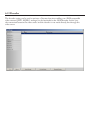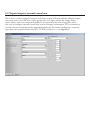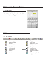
1
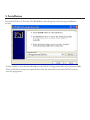
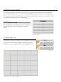
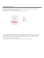
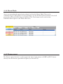
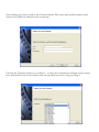
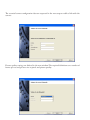
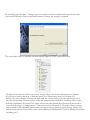
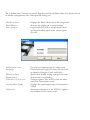
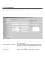
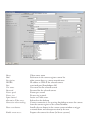
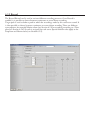
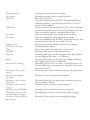
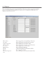
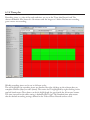
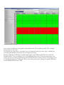
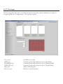
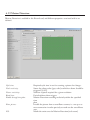
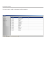
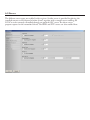
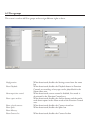
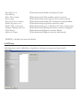
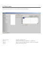
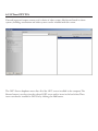
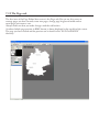
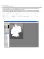
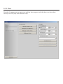
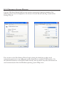
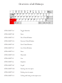
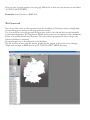
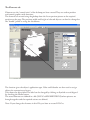
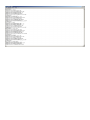
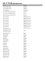
DiViCro
Management Software for network-based video systems
System specification
As at 10/2009
Inhalt
1. Introduction
6
2. System structure
6
2.1 System specification/System requirements
2.2 Access to the operating system
7
7
3. Installation
8
4. DiViCro Desktop/Functions
9
4.1 Menu bar
4.2 Connection control
9
10
4.2.1 Camera circuit 4.2.2 The Split area 4.2.3 The Memory area 4.2.4 Camera directory 4.2.5 The Report area 10
10
11
11
12
4.3 Video displays
4.4 Function control
13
14
4.4.1 Live Mode
4.4.2 Playback Mode 4.4.3 Export Mode 4.4.4 Alarm Mode 4.4.5 Picture export 15
15
16
17
17
5 First steps
18
5.1 Installing a video source
18
6 System configuration
22
6.1 Video displays
6.2 Desktop
6.3 Alarm monitoring
6.4 Export
6.5 Video sources
23
24
26
27
28
6.5.1 Video source 6.5.2 Record 6.5.3 Reports 6.5.4 Time plan 6.5.5 Memory 6.5.6 I/O Control 6.5.7 User login 6.5.8 PTZ Control 6.5.9 Motion Detection 6.5.10 Sabotage Detection 29
32
34
35
37
38
39
40
41
42
6.6 Video server
6.7 Camera list
6.8 Server
6.9 User groups
6.10 Users
6.11 Select camera
6.12 External PTZ Control
6.13 Client OPC DA
6.14 Automation
6.15 Decoder
6.16 Sabotage surveillance
6.17 Inputs/outputs, external control unit
43
44
45
46
47
48
49
50
51
52
53
54
7 Setting up the Programs desktop
55
7.1 Layout Mode
7.2 Editor pages
55
55
7.2.1 The Toolbar 7.2.2 The Pages tab 7.2.3 The Pictures tab 7.2.4 The Text tab 7.2.5 The Elements tab 7.2.6 Project options 55
56
57
58
59
60
8 Service
61
8.1 Statistics
61
8.1.1 Data 62
8.1.2 Export 63
9 Other Program functions
63
9.1 Licensing
63
10 Appendix
64
10.1 Installation of a V Module I/O USB
64
10.1.1 Driver installation 10.1.2 Settings in System Manager 64
65
10.2 Automation
10.3 Hotkeys
10.4 The Page Editor
10.5 Videosources
66
84
88
94
1. Introduction
DiViCro is a management software for network-based video systems.
The use of network-based video systems sets the operator the task of replacing or upgrading
the classic video monitoring processes with their crossbars, monitors and recording systems.
Virtually every video system for network use provides a web browser-based user interface,
although its usefulness is limited for security applications. Operating and display problems
occur, especially when using different video systems simultaneously. Also, systems are often
used that only possess simple functionalities and do not offer recording or Motion Detection.
2. System structure
Structured like a video crossbar, in its basic configuration, DiViCro incorporates 64
inputs and 25 outputs. An IP-based video source can be individually assigned to each input,
and its definition, quality and frame frequency can be calibrated. A number of matching
interfaces is available for this purpose, for the most varied types and different manufacturers.
Functionalities like swivel head control (PTZ) and digital inputs and outputs are also supported,
depending on the product. Each input is equipped with its own Motion Detection, capable of carrying out a series of successive events such as recording or switching. A high capacity crash resistant
picture memory is provided for each channel for recording the video signals, which also offers individual storage on freely adjustable hard disks or data servers.
The 25 outputs are organised as camera windows with unrestricted position adjustment, free to receive video signals driven by the operator or by events. Switching is controlled manually by selecting
a camera from the camera list or using an optional graphic desktop. Automatic
switching can result from different events such as received contacts, Motion Detection or even
through an external system using the optional OPC interface.
Events are saved in a reports list located internally or on external database servers. Each
report is linked to a secure video sequence and can be replayed directly by selection.
An optional enhancement based on the PVis control system can be supplied for showing
position plans and as an automation interface. AutoCAD® DWG and DXF, together with picture
import filters and symbol libraries can be used to set up a function- and user-friendly interface in
line with the standard for management systems. The automation interface can be used to integrate
external systems such as danger warning systems, contacts and buildings control systems into the
video management system.
An optional interface based on the OPC Data Access 2 Standard can be supplied to enable
integration into security and building management systems. This interface allows the entire
functionality of the system to be controlled through an external system using an OPC Data
Access 2 Client Interface.
DiViCro can be expanded as a client/server-based solution for use in large surveillance
systems. Up to 64 video servers can be used to configure networks with up to 4096 video
sources and 1600 outputs. In doing so, the network load is divided among the servers. The
server version also provides a WEB interface, enabling access to platform-independent WEB
browsers. The browser function can be driven on virtually any commercial operating system
such as Windows, Linux, Unix or Apple.
2.1 System specification/System requirements
The quality and picture speed of the video signals is the most important factor for system
performance. Another parameter is the computer hardware and the processing required of the video
sources (Motion Detection, recording). A standard PC (2 GHz, 512 MByte RAM) with a resolution of 640x480 pixels and good picture quality (70%) is capable of processing and supplying up to
120 frames per second, divided among the video sources. The network, the video card and the hard
disk for recording are also very important for speed. The output of 120 frames per second can be
improved by using faster computer components.
Minimum system specification:
•
•
•
•
Windows 2000, Windows XP
Minimum 2 GHz, 256 MB RAM
(Hard disk capacity depends on the requirements)
A good graphics card is recommended.
Optimum system specification for high performance systems
•
•
•
•
Windows XP
Dual Core Processor (2 GHz), 2 GB RAM
(Hard disk capacity depends on the requirements)
High performance graphics card
2.2 Access to the operating system
The operating system and the DiViCro-Software must be protected by setting up suitable authorised access for each user in the operating system’s user management system. It is especially important to protect the configuration file in the DiViCro-Software.
3. Installation
Insert the DiViCro CD in the CD-ROM drive and call up the self-extracting installation
archive.
In this window, select the desired folder for the DiViCro Programme files in Destination folder.
Click on Install to extract the required data from the selected list and select DiViCro.exe to
start the programme.
4. DiViCro Desktop/Functions
The DiViCro desktop is divided into the following three desktop areas, in addition to the menu and
status bars:
Connection Control
The three desktop areas of the DiViCro desktop
4.1 Menu bar
The menu bar contains the following elements: File,
Settings, Cancel and Details.
The system can only be rebooted or shut down with
File. Settings is used to define the complete configuration for camera, server, userdefined desktop
settings, authorised access and users/group passwords
etc. The Cancel tab on the menu bar allows the user
to quit the programme without closing it. Details is
used to show information
about the version number.
Video displays
Function control
4.2 Connection control
The configurations for the Show videos area are selected in the Connection control desktop
area containing Main menu, Camera circuit, Split, Memory, Camera directory and Report.
The number of connected local cameras and the actual number of pictures received per second
are displayed on the status bar at the bottom.
4.2.1 Camera circuit
The saved number of selected cameras is displayed
here(see Section 6.11). Choose Select to start
them.
Camera circuit area
4.2.2 The Split area
The number of camera windows to be displayed in the Show
videos area is selected in the Split area. The maximum
number of camera windows that can be displayed is 25.
Split area
Show videos area with the 5x5 Split option
4.2.3 The Memory area
Here, in addition to preset camera combinations, it is possible to save, name and call up
personalised camera combinations. 80 memory spaces are available.
Memory area
Save Button
Memory button
Navigation keys for the memory
buttons
Procedure: After defining the Show videos area (which includes selecting the number of video displays, positioning and organising the different windows and assigning the video sources), the settings are saved by clicking the Save button. Then left-click on the required memory space.
If desired, the entry can be made with the right mouse button, and confirmed with Enter. This way,
the selected camera combination for the Show videos area is saved at the checked button, and can be
called up at any time.
4.2.4 Camera directory
Every connected camera is displayed in the Camera directory. Colour codes mark the status of
each camera. Local and remote cameras are identified by different symbols in the list.
Motion Detection, Alarm/(picture
failure)
Live Switching active
Recording activated/enabled
Camera not switched on
Camera out of service
local camera
remote camera
To display Live Switching in a camera window, select the desired camera in the camera directory ad use drag&drop to move
it to the required window in the Show videos area.
Camera directory
4.2.5 The Report area
Alarm warnings are displayed here, triggered either by Motion Detection or directly by a user.
The time of the recording, the camera identification and the report type are recorded in the
Report area.
The required alarm recorded in the Report area is played
back by double-clicking on the relevant recording, which
is then pasted in the camera window in the Show videos area. It can then be controlled in the function control
playback mode.
4.3 Video displays
This area is used to display and play back Live Switching and Alarm reports.
Right-click in any display window to call up the associated Context menu, which offers the
following functions:
Disconnect
The camera is disconnected, i.e. Live Switching and playback
are ended.
Full picture:
The selected camera window is displayed in 1x1 mode. When
deactivated, the camera window returns to its original size.
Set position:
The selected camera window can be set to any scale and position.
Show Motion Detection:
This function can only be used if Motion Detection is
enabled(see Section 6.5.9). When the function is enabled,
each recording appears in grey scale, with movements marked
in red.
100% Zoom:
If an area was magnified in a camera window, the 100%
Zoom function in the Context menu resets the picture to the
original resolution.
4.4 Function control
Function control determines the current programme mode. It also provides general control of
the playback mode in the Show videos area.
It is possible to switch between the following functions (modes):
•
•
•
•
•
Live
Playback
Export
Alarm
Export picture
It is possible to display or play back the entire recording (using the Alarm button), or to use the
Export button to export and save only extracts (export in AVI format), or single still pictures
(export in BMP format). During Live Switching, a PTZ control can be used to control the
cameras from the workstation concerned.
The five function buttons illustrated above are used to switch to each mode.
4.4.1 Live Mode
Depending on the camera type, Live Mode can be used through an enhanced function to
remotely control the cameras.
PTZ Control:
Cameras are remotely controlled with PTZ Control. This is provided that PTZ Control is enabled
(see Sections 6.5.8 and 6.12), and the camera is fitted with a swivel function. This enables
Zoom, Focus and Iris, and also the preferred camera position, to be set, saved and called up.
Navigation keys
Starting Point
Dropdown POSITION Menu and
saved positions
A fixed camera position is defined by steering the camera to the required position using the
navigation keys. To save the camera position, select a free memory space in the dropdown
menu and click on the SAVE button to confirm.
To change the name of the saved position, select the required memory space in the POSITION
dropdown menu and [Enter] to confirm. A new name is given, and is saved with the SAVE
button.
The saved camera position can now be called up at any time by clicking the CALL-UP button.
4.4.2 Playback Mode
Playback Mode is only active if recording has been enabled for the camera concerned
(see Section 6.5.2).
Playback in this mode is controlled by recorded Alarm reports or other surveillance recordings.
It is possible to export recording time intervals.
Track start:
Time:
Track end:
Start of recording
Definition of a time interval to be exported or simply viewed
End of recording
Set track start
Set track end
To export an extract of a complete recording, use the navigation keys to set the start and end of
the extract. Only when both points have been set can Export mode be activated and accessed
by clicking on the Export button.
4.4.3 Export Mode
This mode is used to export recordings by means of a defined time interval initiated with the
Start button.
4.4.4 Alarm Mode
Any as yet unconfirmed reports (active alarms) are listed in Alarm Mode. They can be
confirmed singly or all together. It is also possible to use the Archive button to obtain a list of all
previously confirmed alarms (internal database). The View button can be used to view
individual alarm reports in the Show videos area.
4.4.5 Picture export
The Picture export function is used to export the latest single pictures in BMP or JPEG format
directly into the directory provided in Export (see Section 6.4).
5 First steps
This Section describes how to use the Wizard to install a video source and then to display it in a
camera window.
5.1 Installing a video source
Open the Assistant at menu item Settings > New video source. The “Assistant” window
opens at the first installation step:
Video source for display only
• The video source is produced without recording or Motion Detection. The link is only
obtained in the event of a display.
Video source in accordance with BGV-Kassen (Ger- • Permanent link
man Health and Safety Regulation for Cash points) • Motion Detection every 4th picture
• Recording with 15 minutes before and after
an alarm
• Recording in the event of motion on the
standard track
• Suspicion and Alarm recording
• Deletion of standard tracks at < 1 GByte and
those more than 3 days old
• Deletion of Suspicion and Alarm tracks
more than 10 days old
• “Picture failure” report in the event of failure
of the video source
Copy an existing video source
Adopts the settings of a previously installed
camera
After making your choice, click on the Continue button. The name, path and description of the
camera to be added are defined in the second step:
Click on the Continue button to go to Step 3 - to select the manufacturer and type of the camera
to be added. Select the desired camera from the specified camera list and go to Step 4.
The essential camera configuration data are requested in the next step to enable a link with the
camera:
Picture quality settings are defined in the next window. The required definitions are: number of
frames per second, picture size in pixels and picture quality.
By checking the Save data ... buttons, you can confirm all entries made until now, save the data
and end the Wizard. Click on the Back button to change the settings if required.
The new video source is installed and immediately appears in the camera directory:
To obtain a live picture of the new camera, navigate down the Camera directory (see Section
4.2.4) to the camera and drag it with the mouse to a Show videos area (see Section 4.3).
Release the mouse button to create the link with the camera and to view the camera picture in
the selected window. Cameras can be easily and conveniently installed by installing video sources
with the installation Assistant. Each video source can subsequently be selected and processed at
menu item Settings > Configuration > Video sources (see Section 6.5). The video source configuration enables both a detailed optimisation of camera settings (picture speed, picture quality etc.),
and an enhancement of the video sources with additional functionalities (such as Motion Detection,
recording etc.).
6 System configuration
In spite of the easy installation of video sources and their intuitive operation, the DiViCro-System
is an extremely comprehensive and at the same time, flexible software. The
system is fully configured and subsequently optimised in the configuration area, accessed
through menu item Settings> Configuration.
The following tabs are located in the configuration window:
•
•
•
•
•
Video displays
Desktop
Alarm monitoring
Export
Video sources
•
•
•
•
•
•
•
•
•
•
•
User groups
Users
Video server
Camera list
Server
Camera circuit
External PTZ control
OPC DA Client
Automation
Decoder
Inputs/outputs
• Sabotage monitoring
OSD (On-Screen-Displays) configuration
Desktop settings
Configures alarm processes
Specifies directories and further options
Summarises and configures options for video
sources
Defines user groups
Lists installed cameras
Installation of further server functions
Installation of a video server
Assigns users to the groups
Sets up video selections
Installs PTZ control
Installs an OPC Server
Writes scripts
Installation of an external decoder
Configuration of a Suspicion/Alarm input and
an error output
Changes recording settings
6.1 Video displays
The camera windows of the Show videos area are configured in this Record card, i.e. all the
information must be set before it can be displayed.
In the Show text box, information is displayed in the single camera window, enabled as a userdefined
setting with 4 positions using a dropdown menu, e.g. with time information top left,
camera name top right, frames per second bottom left. Different settings are possible,
according to whether the user is in live or playback mode. The dropdown menus provide the
following setting options:
None:
No display at this position of the Show
videos area
Camera name:
Camera manufacturer’s name
Monitor name:
Monitor1-Monitor25
URL:
Connection path to the camera
Time:
Time of recording display
Picture Counter
Picture counter, identification no. of all
received pictures
Description:
User-defined camera description
Resolution:
Picture resolution in pixels, horizontal/
vertical
Motion Detection: Motion Detection with red marking
Pictures per sec:
Picture playback in seconds
Record ID:
External values (identity) that can be
saved for a record.
Picture Size:
Picture size in bytes
Record Data:
External values (data) that can be saved
for a record.
Text font, size, background colour (including transparent) are also set here for the text boxes in
the information display.
The recommended default for the pictures per cycle setting is 100 (min. 10 and max. 1000).
This value represents the maximum number of frames per second in all connected video
displays.
6.2 Desktop
The user-defined appearance of the user window, i.e. the DiViCro desktop is set here.
The top left part of the screen is intended to be the zero position (start point) for the “left
position” and “top position” settings in the boxes in each of the 3 desktop areas. The input
values are pixel data.
The 3 desktop areas Connection control, Function control and Show videos (see Section 4) can
be hidden at programme start. Other possible settings are:
Window to front:
Dual Monitor:
Start-up logon:
Displays the Show videos area in the foreground
Activates the display on a second monitor
Logon exclusively with a user password; the logon/logoff window opens at the next programme start
Authorisation server
Language:
Uses the user administrator of a video server
Choice between English, German, French, Italian, Spanish, Potuguês, Czech and Polish
Show videos default setting at programme start
Activates the use of hotkeys
Changes between Tree and List view for video
sources in Connection control
Displays the input/output status in Connection
control
Automatic adjustment of the DiViCro- application window on the current screen
Memory at Start:
Enable hotkeys:
Video sources in List view
Activate Status display
Full picture:
6.3 Alarm monitoring
You can use this Record card to activate/configure report sending by e-mail and to assign the
Alarm display to a specific camera window
Overwrite oldest alarm:
Internal database as a ring buffer:
Alarm audio file:
Show alarm on:
New alarms overwrite the alarm picture already displayed on
the selected monitors
Writes the set number of entries to the database, and overwrites them from the start when the maximum number is reached
Plays back the audio file in cycles (provided the pointer is set)
when an alarm is triggered
A specific camera window is assigned for showing alarms
6.4 Export
A file is named at Export > Default path for placing picture material on the hard disk. Files in
AVI format, or optionally BMP or JPEG format, are exported to this file. The quality of the
exported picture material is expressed as a percentage (%). Single pictures (snapshots) can be
taken by operating the picture export button in Function control while a video source is
switching. A picture is saved for every click on the button (see Section 8.1.2).
Export default path
Export quality
Picture file name
Export FTP sender enabled
Sets the path on which exported data are to be
saved
The output quality can be reduced here Sets the export file name and type
Exports files to a (remote) FTP server using
FTP-Protocol p When a file name is selected at Picture file name, any previously existing files are
overwritten at each export operation. If no file name is entered, an internal file with a
name including the date and time of the export is allocated at each export operation.
6.5 Video sources
The currently connected cameras are listed in the Video sources Record card with the
identification number, name and description. Cameras can be immediately removed from this
list by clicking the Delete video source button. The New video source and Edit video source are
used to open the Camera settings sub-menu, where new cameras can be added or details of
existing cameras can be edited.
6.5.1 Video source
The Camera settings sub-menu accessed through the New video source button contains 10
Record cards: Video source, Record, Reports, Time plan, Memory, I/O control, User logon, PTZ
control, Motion Detection and Sabotage Detection. All camera data and settings are stored
here. The settings of existing cameras can be copied using the Copy from ... button.
•
•
•
•
•
•
•
•
•
•
Video source
Record
Reports
Time plan
Memory
I/O control
User logon
PTZ control
Motion Detection
Sabotage Detection
Adds and configures a new video source
Enables recording
Sets up Alarm reports
Installs a time plan
Edits maximum file size and deletes settings
Sets and reads external contacts
Defines user authorisations
Installs PTZ control
Enables and configures Motion Detection
Enables and configures Sabotage Detection
Name:
Path:
Description:
IP/URL:
Port:
User name:
Password:
Picture speed:
Picture size:
Input channel:
Alternative Video source:
Connection when tracking:
Show event button:
Enable remote access:
Video source name
Path name in the camera register camera list
other camera data e.g. camera manufacturer
IP address or URL of the selected camera
associated port (Standardport 80)
User name for the selected camera
Password for the selected camera
Frames per second
Picture size in pixels
Active on Video server
Selected on the desktop
Camera connection is set up using drag&drop to move the camera
from the camera register to the camera window.
Installs the user button in the current camera window to trigger
a manual alarm and subsequent action by the user
Prepares the camera for clients (in Server systems)
Mode change with alarm:
Mode change with display:
Mode change with no
recording:
Upgraded decoder
Selects alternative camera settings in alarm mode
Selects alternative camera settings in display mode
Selects alternative camera settings in no recording mode
(No recording mode must be active in the Time plan tab)
Provided it is supported by the camera, the upgraded decoder
offers a significantly faster display of JPEG pictures
Playback via alternative video The alternative source is played back in Playback mode
sources:
It is therefore possible, for example, to obtain a Live display
based on an ActiveX and a MJPEG recording from a source.
Provided that an alternative video source has been defined, a
checkbox marked “ALT” appears at the bottom.
To achieve this, the status bar display must be shown in the
Desktop configuration.
Test:
Camera connection test; correct connection data with picture
display in the check window above
Source type:
Camera type and data format selection ( JPEG, MJPEG, MPEG
etc.)
6.5.2 Record
The Record Record card is used to activate different recording processes. Once Record is
enabled, it is possible to choose between continuous or event-driven recording.
Target path is used to define a path in which the recordings made by this camera are stored. It
is then possible to choose between continuous or event-driven recording. There are different
event options, for example Motion alarm (see Section 6.5.9) or recording according to a Time
plan (see Section 6.5.4). A track is assigned for each event. Special deletion rules apply to the
Suspicion and Alarm tracks (see Section 6.5.5).
Enable recording:
Target path:
Cycle time:
GOP values:
Pre-alarm:
Post-alarm:
Snapshot event:
Continuous recording:
Track:
Standard:
Suspicion:
Alarm:
Event-driven recording:
Recording in the event of
motion:
Recording according to a
time plan:
Recording in the event of a
user action:
Recording in the event of a
trigger
Recording via an OPC Item
Recording in the event of an
activated suspicion trigger
Recording in the event of an
alarm trigger
Activation is needed to start recording
Recording memory location on the hard disk
Recording cycle in ms
Note: In compliance with the BGV (German Health and
Safety Regulation), ensure that the cycle time is set to 2.5
frames/second (400ms)
Frames per block (Group of Pictures): The value entered here
gives the maximum size of the file to be recorded. Once this
value is reached, a new file is automatically created.
Start of recording time (in seconds) before an alarm
End of recording time (in seconds) after an alarm.
Note: In compliance with the BGV, ensure that the pre- and
post-alarm times are each set to 900s (15 min.)
Records the specified number of frames for a snapshot
Uninterrupted recording
Selects the track to be used for the current event.
Recording takes place on the Standard track
Recording takes place on the Suspicion track. Special deletion rules apply to this track -> see Memory
Recording takes place on the Alarm track. Special deletion
rules apply to this track -> see Memory
Recording only in case of an event, i.e. when at least one of
the three following event options are activated: motion, time
plan or user action
Recording in the event of motion in the pre-designated area
Recording in the pre-designated timeframe
Recording when the user operates the event key, only for as
long as the key is held in.
Recording when a specific signal is triggered
Recording when a specific data item is triggered
Recording in the event of an activated suspicion trigger.
Recording in the event of an activated alarm trigger
6.5.3 Reports
This card enables alarm reports triggered by Motion Detection or alarms triggered manually by
the user to be defined. The message gives the report text to be displayed subsequently in the
Report area (see Section 4.2.5).
Motion alarm
User alarm
$ input trigger alarm
OPC Item alarm
Error alarm
Sabotage alarm
Message
Memory
Memory call-up for the
client
Alarm triggered by activating Motion Detection
Alarm triggered by activating the User button
Alarm triggered by activating an input
Alarm triggered by activating a specific data item
Alarm triggered by a software error
Alarm triggered by Sabotage
Output text displayed in the Reports window
Preset triggered on Alarm
Preset called up for the connected network client
6.5.4 Time plan
Recording times, e.g. day of the week and time, are set on the Time plan Record card. The
shortest definable time interval is 30 minutes and the longest is 8 hours. Red means recording,
green means not recording.
Weekly recording times can be set in 24-hour cycles.
The red highlights for recording times are obtained by right-clicking on the relevant box, on
complete columns (days) or rows (times). The entire area is highlighted by right-clicking in the
top left-hand corner. These boxes can be de-highlighted (to green) with the left mouse button.
The time interval for the table setting is defined with Trigger. The Standard time plan means
that the default recording settings defined in the Video sources Record card are used.
Let us now consider the two graphics (Standard mode, No-recording mode). This example
demonstrates a few cases:
On Sunday, the entire day is recorded, since in Standard mode, the entire day is enabled for
recording (Standard mode always has the highest priority).
Between Monday and Friday, recording takes place from 0000 until 0730 in line with the
Standard Plan. As no recording times are highlighted there after 0730, the programme now
checks the No-recording mode and records until 1230 in line with it. Since no recording times
are highlighted between 1230 and 1700, no recording takes place during this period. (Returns
to the Standard Plan from 1700).
6.5.5 Memory
The Memory Record card is used to define a maximum memory limit for recording video
sources. Once activated, an alarm report is issued as soon as the memory limit is reached. It is
also possible to set the time at which a recording should be deleted or moved.
Note: In the configuration conforming to the BGV (German Health and Safety Regulation), the
time for the deletion of Suspicion and Alarm tracks must be set to 10 days.
6.5.6 I/O Control
The I/O Control Record card allows the user to set and read external contacts.
Enable inputs:
Cycle/ms:
Enable when connected:
Input $$ Name
Output $$ Name
Enables management of external contacts
Sets the number of requests in milliseconds
Enables administration only when the equipment is switched
on
Gives input names
Gives output names
6.5.7 User login
The User login Record card is a user administration card, used to allocate different user rights to
assigned groups (see Configuration -> User groups register).
User groups
LIVE only:
PLAYBACK only:
CONTROL only:
Add group:
Remove group:
Installed user groups
Contains groups only authorised to use Live Mode
Contains groups only authorised to use Playback Mode
Contains groups only authorised to use Control Mode
Adds a selected group
Removes a selected group
6.5.8 PTZ Control
The PTZ Control Record card enables PTZ lines set in Configuration -> external PTZ Control to
be triggered.
PTZ Line:
PTZ Address:
PTZ Speed:
PTZ Monitor
Event
$ PTZ Position
Wait
Take pictures
Uses a line set in Configuration -> external PTZ Control
Sets the PTZ address
Sets the PTZ Control speed
Sets the output monitor for crossbar controlling.
Event triggers crossfire recording
Steers the camera to the set PTZ position
Holds the camera in position for a preset time in ms
Number of frames to be shot
6.5.9 Motion Detection
Motion Detection is enabled in this Record card, and different properties associated with it are
defined.
Cycle time:
Pixel sensitivity:
Picture sensitivity:
Break time:
Enable through time plan:
Enter picture:
Fill:
Required cycle time in ms for scanning a picture for changes
States the colour value (grey scale) at which an alarm should be
triggered [1-255]
Number of pixels required for a given resolution
Period without alarm triggers
Motion Detection recording exclusively within the specified
time
plan
Installs the picture from a surveillance camera, i.e. sets up a camera connection in order precisely to mark out the surveillance
area.
Marks the entire area for Motion Detection (red screen)
6.5.10 Sabotage Detection
It is possible here, individually for each video source, to activate Sabotage Detection, to detect
changes to the video signal by comparison with a reference picture, and to report them if
necessary.
6.6 Video server
Up to 64 servers can be added and processed. An DiViCro videoserver manages up to
64 local cameras, i.e. a total of 4096 cameras can be networked. When a server is added, its
name appears in the Video server Record card. Click on the relevant server to view the setting
details in Server Info.
6.7 Camera list
Lists every camera already in the network and their properties.
6.8 Server
The different server types are enabled in this register. A video server is provided for placing the
installed cameras at the disposal of other clients, together with a control server enabling the
DiViCro to be remotely controlled through an optional OPC server. The alarm server
prepares reports for the networked clients. The WEB and FTP servers are also enabled here.
6.9 User groups
This screen is used to add User groups and to assign different rights to them.
Configuration:
Show Playback:
Camera position control:
Show reports archive:
Show selected cameras:
Show Splits:
Show Memory:
Show Camera list:
When deactivated, disables the Settings menu from the menu
bar
When deactivated, disables the Playback button in Function
Control; no recordings of any type can be played back in the
Show videos area.
When deactivated, camera control is disabled, Live mode is
deactivated in the Function Control area
When deactivated, disables the Archive button and the confirmed alarm reports in the Alarm mode of the Function Control
area.
When deactivated, disables the Camera circuit box
When deactivated, disables the Splits box
When deactivated, disables the Camera list box
Show Reports list:
Save Memory:
Move Video window:
Remote logon:
Show Connections window:
Enable Programme end:
Enable Video context menu:
Configure Sabotage Detection:
Delete Reports:
Administer Export:
When deactivated, disables the Reports list box
When deactivated, Video window cannot be moved
When deactivated, remote logon to this account is denied
When deactivated, disables the Connections control window
When deactivated, programme cannot be ended
When deactivated, access is denied to the Video context menu
When deactivated, Sabotage Detection cannot be configured
When deactivated, Reports cannot be deleted
When deactivated, Exports cannot be administered
ADMIN is a default and cannot be deleted.
6.10 Users
Individual users can be added here, assigned to an existing user group, and a password is
requested.
6.11 Select camera
This Record card is used to set camera switch-on times and positions.
Time in seconds
Memory
Camera
Position
Sets the step display time
Selects the memory to be called up -> see Memory
Selects a camera for which position control is also required.
Selects the camera position.
6.12 External PTZ Control
This Record card is used to configure the PTZ control for connected cameras.
This is done by specifying a PTZ type, the relevant interface and connection settings
6.13 Client OPC DA
External input and output contacts and a choice of other systems like fire and break-in alarm
systems, buildings automation and video systems can be installed with this screen.
The OPC-Server dropdown menu lists all of the OPC servers installed in the computer. The
Browse button is used to view the selected OPC server and its items in the box below. These
items can then be installed in DiViCro by clicking the Add button.
6.14 Automation
This Record card enables personal scripts to be set up, using the default system variables and
installed OPC Items provided for the purpose.
test $KeyF1 =1
$SelectCamera=1
$ConnectMonitor=1
end
test $KeyF2=1
$SetMatrix=4
$SelectCamera=1
$ConnectMonitor=1
$SelectCamera=2
$ConnectMonitor=2
$SelectCamera=3
$ConnectMonitor=3
$SelectCamera=4
$ConnectMonitor=4
end
Operate Key F1 to connect Camera 1 to
Monitor 1
Operate Key F2 to call up a 2x2 Split (4) and
to connect Camera$ to Monitor$
6.15 Decoder
The decoder setting can be used to activate a Gateway function enabling non AXIS-compatible
video streams ( JPEG, MJPEG, analogue) to be forwarded to the AXIS decoder. In this case,
the connection between the video source and the decoder is not made directly, but through the
video server.
6.16 Sabotage surveillance
Activating the Enable Sabotage surveillance option at menu item New video source gives the
opportunity to activate changed recording settings at specific times. The area required is
selected in exactly the same way as for the Time plan (see Section 6.5.4).
6.17 Inputs/outputs, external control unit
This screen is used to configure suspicion and alarm contact utilisation and the collective output
for system errors. An OPC item can be specified for each input and for the output. Video
source failures and server connection problems are reported by the error output. This tab is
also used to configure external control units used to interpret and transpose PTZ commands or
recorder control commands sent by networked peripherals. No further configuring is required,
apart from one exception (Panasonic WV-CU 650 control unit -> see Appendix).
7 Setting up the Programs desktop
7.1 Layout Mode
To deactivate/activate the Graphics mode, change to Layout
modeand click on the Graphics checkbox to install or
remove created pictures and graphics.
7.2 Editor pages
7.2.1 The Toolbar
Create new page
Open selected page
Save page
Import AutoCAD
Cut (Clipboard)
Copy (Clipboard)
Paste (Clipboard)
Zoom out
Zoom in
Fit page
Delete object
Bring object to front
Send object to background
Select pointer
Open a text box
Add/change screen
Remove/add parameter
guide
Page preview (ALT + F4
to quit)
7.2.2 The Pages tab
The first item of the Page Editor Start screen is the Pages tab. You can use this screen to
manage pages you have created, create new pages, change page height and width and to
name pages you want to save.
Always make sure that you make changes with the red bracket.
A reduced whole page preview in BMP format is always displayed at the top left of the screen.
The page you have created and the preview can be found in the “\DiViCro\PAGES”
directory.
7.2.3 The Pictures tab
You can use this screen to select pictures from the checkbox at the bottom and use drag&drop
to move them in any format to the page you have created.
Use Left and Top to set the position of the picture, unless it has already been moved manually
to the required position. The Height and Width of the picture can be adjusted in the checkboxes
below, or manually, directly on the picture. The ratio remains proportional only as long as the
relevant checkbox is activated.
Picture transparency is also adjusted in the checkbox.
The Fit function ensures that the picture graphic fits the picture in the event of size changes.
All pictures are kept in BMP format in the “\DiViCro\PICTURES” directory.
7.2.4 The Text tab
This tab enables you to create any number of text boxes and position them on the page. To do
this, click on the “Open text box” symbol on the toolbar and then on the position on the page
where you want to place your text passage. Now, you can write your text. To change or edit
text, click on the relevant text object and then on the “Open text box” symbol on the toolbar.
To change the symbol set, click in the “Symbol set” box.
7.2.5 The Elements tab
Elements are the “control units” of the desktop you have created. They are used to produce
and control graphics with functions.
The elements are moved using drag&drop from the list or preview picture to the required
position on the page. The position, width and height of selected objects can then be changed at
the “handle” points or using the checkboxes.
The function gives the object’s application type. Value and Subvalue are then used to assign
objects for connection or for use.
Text shows the object label. The label can be changed by clicking on Symbol set and aligned
by checking the Radio button.
The actual elements are defined in a file (\DiViCro\ELEMENTS.INI) where pictures are
brought together and the required actions are defined.
7.2.6 Project options
Settings for organising page displays are provided under Project > Options in the menu. This
allows you to decide how to split and align your pictures, the positions they occupy and which
page should be displayed at Start.
8 Service
8.1 Statistics
This screen gives a graphic display of the current CPU workload and hard disk space used,
together with picture speed and data flow information.
8.1.1 Data
Provides the opportunity to copy, move or delete alarm reports and video data or to burn them
directly onto CD (only with Windows XP).
8.1.2 Export
Provides access to snapshots taken, with the opportunity, in addition to showing them, to copy,
move or delete them, or to copy them directly to CD (only with Windows XP).
9 Other Program functions
9.1 Licensing
This option is used to add and remove Dongle drivers and licenses.
10 Appendix
10.1 Installation of a V Module I/O USB
10.1.1 Driver installation
Switch the computer on and start Windows. Now
wait until the desktop has finished loading, then
connect the VModule with the USB cable to the
USB
port on your PC.
When the USB connector has been plugged in, the
operating system reports that it has found a USB
component and asks for a suitable driver in order to
install the unit in Windows. Select manual
installation and go to the directory containing the
video management software, for example
C:\Programme\DiViCro\VModul_IOMini to
enable Windows to install the module driver. You
will then be able to use Windows System Manager
to
control the entries to the USB module.
Start the System Manager by clicking on Start >
Settings > System Manager, then double-click on
System. Select the System manager Record card,
where you will find the USB components first at
Computer > Connections and secondly at USB
Controller.
The corresponding USB components should be
displayed here:
- USB Controller
- USB Serial Converter
10.1.2 Settings in System Manager
Click on USB Serial Port(COM5) to exit and then activate the Properties checkbox. The
following entries must be displayed on the relevant General Record card (Fig. 1) and in Port
Settings (Fig. 2):
You can now use the Port Settings Record card to change the baud rate or other serial
connection parameters to any values you usually obtain from a standard COM interface. Use
the Advanced button to set the FIFO buffer memory. You can obtain any other information on
serial communication from the Windows operating system Help screen.
10.2 Automation
In the Scriptlanguage is a new instruction implemented for control of Split of the 2nd monitor.
$SetMatrix2
Analog to the command „$SetMatrix“ for the 1st Monitor, this command applies to the Split of the
2nd Monitor.
Example:
$SetMatrix2=4 - applies the
2. Monitor up to a
2x2-Matrix
Following new variable has been integrated:
$CameraNNNNAlarmeAcknowledged
This Variable delivers the value 1, as soon as a message of the affected Videosource has been confirmed over the Alarmlist. The Variable can be interrogate with the command TEST.
Example:
test $Camera0001AlarmeAcknowledged=1
... [commands]
end
New Commands since the Version 1.7.01 Build 321 Beta
$CameraNNNNOverExposureAlarme
Videosource reports alarm of overexposure
$CameraNNNNUnderExposureAlarme
Videosource reports alarm of underexposure
$CameraNNNNAnalysisAlarme
Videosource reports Alarm from analysis
$CameraNNNNAnalysisValue
optional value of analysis
$CameraNNNNError
failure of the Videosource
$CameraNNNNSabotageAlarme
Sabotagealarm has been triggered for the Videosource
$MonitorControl_PTZUp
$MonitorControl_PTZDown
$MonitorControl_PTZLeft
$MonitorControl_PTZRight
$MonitorControl_ZoomNear
$MonitorControl_ZoomFar
$MonitorControl_FocusNear
$MonitorControl_FocusFar
$MonitorControl_IrisClose
$MonitorControl_IrisOpen
$MonitorControl_IrisAuto
$MonitorControl_FocusAuto
Trackcontrol_PlayForward
TrackControl_PlayBackward
TrackControl_PlayFastForward
TrackControl_PlayFastBackward
TrackControl_PlayFastBackward
TrackControl_PlayFastBackward
TrackControl_TrackStart
TrackControl_TrackEnd
TrackControl_NextImage
TrackControl_PreviousImage
From now on a subprogram will run at the start up and the end of the program in the Automation,
if it has been defined.
At the start up of the Program the Call of the Program „Startup“ occurs.
Example:
Program Startup
$Camera0012PresetPosition=2
End
The videosource 12 will launch the PTZ-Position 2 at the start-up of the program.
The Call „Shutdown“ occurs at the end of the program.
Example:
Program Shutdown
$Camera0012PresetPosition=1
End
The Videosource 12 will launch the PTZ-Position 1 at the start-up of the program.
The execution of the program is limited to 3 seconds.
Since Version 1.5.07 Build 281 two auxiliary variables, which can be read and written as bidirektional strings, with name
$CamerannnnAux01
$CamerannnnAux02,
has been integrated for each videosource.
Example:
test $KeyF1=1
$Camera0001Aux01=Test
end
test $Camera0001Aux02=1
$SelectCamera=3
$ConnectMonitor=1
end
This auxiliary variables are supported by the VM OPC Server since version 1.6.
In Version 1.5.05 Build 274 the Automail has been upgraded by the command to activate a
Snapshot.
It is called.
$SnapShot=1
The filename of the last executed Snapshot can be detected anymore:
$LastSnapShotFile
Furthermore it is possible to sen e-Mails in the Automation now. The E-Mail notice of the alarms
are absobing the account adjustment. From now on the following Variables are available in the automation:
$MailTo=[receiver E-Mail accountof the Message]
$MailSubject=[title of the message]
$MailMessage=[Text of the message]
$MailAttachFile=[Path and name
$SendMail=1
attached file
send the mail
Example:
test $KeyF1=1
[email protected]
$MailSubject=This is a testmail
$MailMessage=the quick brown fox jumps over the lazy dog
$MailAttachFile=$LastSnapShotFile
$SendMail=1
end
Concealing the Start-and End dialog
The start-up and the ending dialog cn be conceales for the execute as a service.
The function happens through the following entry:
[DESKTOP]
WaitWindowHide=1
If all dialogs are hidden, no monitoring occurs to the ending of the program.
The PTZ-Control of ActiveX Videosources
With the command „TRIGGER“ it is possible to execute commands for a certain time daily.
The command has the following Syntax:
TRIGGER [Time]
... Commands
END
The time has to be shown in hour:minute, whereas the formatting of the local adjustment has to be
observe.
Example:
TRIGGER 12:48
$SelectCamera = 3
$ConnectMonitor = 1
END
„Videosource 3 is connecting to Monitor 1 at 12:48“
MPEG4 Assignment
The assistance of the MPEG4-Format supports now optional theassignment between Server and
Clients. The assignment can be activated by the following entry in the INI-File.
[SYSTEM]
CodecSupport=1
Version 1.4.22 Build 214
A new command, which enabled thedelay of the next step achievment, has been implemented:
WAIT [n] [n] = holding time in seconds
Example:
WAIT 4 Wait 4 seconds and then make the next step.
Version 1.4.20 Build 21
Hard disk monitoring
All messages of the hard disk monitoring can be written in the file ‚HDCONTROL.LOG‘ through
the configuration file:
[SYSTEM]
LogHDControlMessages=1
Version 1.4.16 Build 204
Videoserver
The self-test of the videoserver can be choose optional now. The clearing results from the following
entry:
[SYSTEM]
EnableVideoServerCheck=1
Videoserver
For the compensation of the demand, the maximum frame rate of the videoserver, dependet on the
number of the client connections, will be reduced.
This Function can be disconnected by the following entry in the .INI file optional:
[SYSTEM]
DisableClientStreamingLimit=1
The Compensation results from the following parameters:
> 50 Client connections: Imaging cycle limited on 1s
> 40 Client connections: Imaging cycle limited on 800ms
> 30 Client connections: Imaging cycle limited on 600ms
> 20 Client connections: Imaging cycle limited on 400ms
> 10 Client connections: Imaging cycle limited on200ms
beneath this barrier: Imaging cycle on image source with up to 40ms
PTZ-Control
The display of the CGI-Camera command can be controlled now, for the PTZ-Controll via an
extern control panel.
The previous buffering can be deactivated by the entry
[IOCONTROL]
LockMultipleCGICommands=1
and the command can be forwarded to the Videosource directly. The entry of 0 activates the buffering.
Performance-Monitor
For testing purposes within the logfile.display you can display an overview of all important processs
with the associated terms now, by the entry
[DESKTOP]
PerformanceMonitor=1
in the .INI-File.
Backup of Videotracks
A parallel backup of Videotracks from all Videosources on an extarnal directory can be made by a
seperate entry in the .INI-file.
That occurs by the following entry:
[BACKUP]
BackupStandardTracks=
1 = Backup Standar Tracks
BackupSuspicionTracks=
1 = Backup Suspicion Track
BackupAlarmeTracks=
1 = Backup Alarme Tracks
BackupPath=
Target path for backup
128 entries will be secured in a Ringmemory during an unsuccesful backup. This setting takes place
for all Videosources simultancously.
Starter program RESTART.EXE
The starter-program has been extended by a dely in the program execution. This allowed a delayed
start of the Videomanagement, particulary the execution of the Windows-Autostart.
To this you have to create a Batch-File, which has to be add in the Autostart instead of the Videomanagement. The following has to be entered in the Batch-File:
RESTART Programname [Delay in seconds]
for example
RESTART DIVICRO.EXE 30
RESTART SINVR.EXE 30
RESTART ZELARIS_IP.EXE 30
for a Delayed Start of 30 Seconds.
Remote Setting from variables in the Automation
Now it is possible to set variables in the automation, which are lying on a videoserver. The Targetserver is defined by an attached @ (at) on the variable name.
The variables only let describe, but not to read. The server has to be defined in the Videoserver configuration and the controlserver has to be registered for this.
Example:
Test $KeyF1 = 1
$SetMatrix@LOCALHOST=1
[Audio Volume control Volume control Mute]@LOCALHOST=1
End
Test $KeyF2 = 1
$SetMatrix@LOCALHOST=2
[Audio.Volume control Volume control Mute]@LOCALHOST=0
End
When pressing the F1 key on the Client, the Matrix 1 will be set on the Server „LOCALHOST“
and the defined OPC-Datapoint will be labelled with the value 1.
When pressing the F2 key on the Client, the Matrix 2 will be set on the Server „LOCALHOST“
and the defined OPC-Datapoint will be labelled with the value 0.
New Systemvariables at the Automation
Function keys:
$KeyF1
call of the Function key F1
$KeyF2
call of the Function key F2
$KeyF3
call of the Function key F3
$KeyF4
call of the Function key F4
$KeyF5
call of the Function key F5
$KeyF6
call of the Function key F6
$KeyF7
call of the Function key F7
$KeyF8
call of the Function key F8
$KeyF9
call of the Function key F9
$KeyF11
call of the Function key F11
$KeyF12
call of the Function keyF12
Example (When pressing the function key F1 to F4, then selection of a Preset:
Test $KeyF1 = 1
$Preset = 0
End
Test $KeyF2 = 1
$Preset = 1
End
Test $KeyF3 = 1
$Preset = 2
End
Test $KeyF4 = 1
$Preset = 3
End
Controlcomannds:
$SelectCamera
Select Videosource
$SelectMonitor
Select Display
$ConnectMonitor
Connection of Monitor and selcted Camera
$LiveMode
Calling Live Display
$PlayMode
Calling play Display
$SetMatrix
Calling Split
Example (When pressing the function key F5 to F12, then controlcommands:
Test $KeyF5 = 1
$SelectCamera=1
End
Test $KeyF6 = 1
$SelectCamera=2
End
Test $KeyF7 = 1
$SelectCamera=3
End
Test $KeyF8 = 1
$SelectCamera=4
End
Test $KeyF9 = 1
$ConnectMonitor=1
End
Test $KeyF11 = 1
$LiveMode=1
End
Test $KeyF12 = 1
$PlayMode=1
End
The command „TEST“ has been extended by a query of an indefinitely change of an OPC-Item.
the Syntax is called:
TEST variable <>
instruction
END
The instruction will be executed at all changes of the OPC-Item here.
The list of the OPC-Items will not be updated by closing the Configuration dialog, but directly on
the Call of the Automation-tab.
The easy Scriptlanguage allows you to monitor the OPC-files and the the internal variables, also it is
allowed to set any values.
The following commands will be available:
Command
TEST
The command TEST initialized the value, followed from the applications and finished with the
command END.
Syntax:
TEST variable=value
instructions
END
Command PROGRAM
The Command PROGRAM initialized the definition of a sub-program, followed by theinstruction
and the finishing command END
Syntax:
PROGRAM programname
instructions
END
Command CALL
call in a sub-program. The program has to be defined in front of the called line.
Syntax:
CALL programname
OPC-Data points will be characterized with closed square brackets
(Example: [System.IOControl.In01]), Systemvariables by a prefixed dollarsign ($name).
The OPC-Data points will be predefined by the OPC-Client, the Systemvariables are given internal.
The Following are given at the time:
$Preset
current memory
$Sequence
current tour
Value 0..79, Read and Write
Value 0..8, Read and Write
$CameraNNNNPresetPosition Value 1..32, only write
PTZ-Control of the camera NNNN, 0001 bis 0064
$CameraNNNNUserEvent
Value 0 oder 1, read and write
user event of the camera NNNN, 0001 bis 0064
$CameraNNNNInput01
Value 0 oder 1, only read
input channel 01 of the camera NNNN, 0001 bis 0064
$CameraNNNNInput02
Value 0 oder 1, only read
input channel 02 of the camera NNNN, 0001 bis 0064
$CameraNNNNInput03
Value 0 oder 1, only read
input channel 03 der Kamera NNNN, 0001 bis 0064
$CameraNNNNInput04
Value 0 oder 1, only read
input channel 04 of the camera NNNN, 0001 bis 0064
$CameraNNNNInput05
Value 0 oder 1, only read
input channel 05 of the cameraNNNN, 0001 bis 0064
$CameraNNNNInput06
Value 0 oder 1, only read
input channel 06 of the camera NNNN, 0001 bis 0064
$CameraNNNNOutput01
Value 0 oder 1, read and write
output channel 01 of the cameraNNNN, 0001 bis 0064
$CameraNNNNOutput02
Value 0 oder 1, read and write
output channel 02 of the camera NNNN, 0001 bis 0064
$CameraNNNNOutput03
Value 0 oder 1, read and write
output channel 03 of the camera NNNN, 0001 bis 0064
$CameraNNNNOutput04
Value 0 oder 1, read and write
output channel 04 of the camera NNNN, 0001 bis 0064
$CameraNNNNOutput05
Value 0 oder 1, read and write
output channel 05 of the camera NNNN, 0001 bis 0064
$CameraNNNNOutput06
Value 0 oder 1, read and write
output channel 06 of the camera NNNN, 0001 bis 0064
Exampleprogram: (The program select the Preset 1, as soon as at the OPC-Item occurs the value.)
Program Intrusion
$Preset=1
End
Test [Audio.Volume control Volume control Mute] = True
Call Intrusion
End
List of all commands
$CameraNNNNOverExposureAlarme
Videosource reports alarm of overexposure
$CameraNNNNUnderExposureAlarme
Videosource reports alarm of underexposure
$CameraNNNNAnalysisAlarme
Videosource reports Alarm from analysis
$CameraNNNNAnalysisValue
optional value of analysis
$CameraNNNNError
failure of the Videosource
$CameraNNNNSabotageAlarme
Sabotagealarm has been triggered for the Videosource
$MonitorControl_PTZUp
$MonitorControl_PTZDown
$MonitorControl_PTZLeft
$MonitorControl_PTZRight
$MonitorControl_ZoomNear
$MonitorControl_ZoomFar
$MonitorControl_FocusNear
$MonitorControl_FocusFar
$MonitorControl_IrisClose
$MonitorControl_IrisOpen
$MonitorControl_IrisAuto
$MonitorControl_FocusAuto
Trackcontrol_PlayForward
TrackControl_PlayBackward
TrackControl_PlayFastForward
TrackControl_PlayFastBackward
TrackControl_PlayFastBackward
TrackControl_PlayFastBackward
TrackControl_TrackStart
TrackControl_TrackEnd
TrackControl_NextImage
TrackControl_PreviousImage
$SelectCamera
Select Videosource
$SelectMonitor
Select Display
$ConnectMonitor
Connection of Monitor and selcted Camera
$LiveMode
Calling Live Display
$PlayMode
Calling play Display
$SetMatrix
Calling Split
10.3 Hotkeys
Hotkeys in the Automation:
As at Version 1.3.12
Build 134
Since the Update to Version 1.3.11 Build 133 a new command in the automation enabled the Use
of Hotkeys.
The definition results of the command „HOTKEY“ followed by indicating the allocating keyboardcode:
HOTKEY=<button definition>
Command
End
The button definition consistsof any combination of the buttons
• CTRL
• ALT
• SHIFT
and a letter-, funtion- or number button. Each of theam has to be combined by a plus sign.
If the relevant Hotkey is already in use, it cannot be allocated another time.
Example:
HOTKEY=CTRL+ALT+SHIFT+A
$MonitorControl_PTZRight = 10
END
HOTKEY=CTRL+ALT+SHIFT+Z
$MonitorControl_PTZRight = 0
END
Overview of all Hotkeys
CTRL+SHIFT+A
Toggle Alarmlist
CTRL+SHIFT+B
Pause
CTRL+SHIFT+C
First Video Window
CTRL+SHIFT+D
Previous Video Window
CTRL+SHIFT+E
Next Video Window
CTRL+SHIFT+F
Last Video Window
CTRL+SHIFT+G
Pause
CTRL+SHIFT+H
Playmode
CTRL+SHIFT+I
Live
CTRL+SHIFT+J
Snapshot
CTRL+SHIFT+K
Logoff
CTRL+SHIFT+M
Starting time for export
CTRL+SHIFT+N
Ending time for export
CTRL+SHIFT+O
Calling and hiding of the export-area
CTRL+SHIFT+P
Image Backwards
CTRL+SHIFT+Q
Image Forwards
CTRL+SHIFT+R
Navigation to beginning of the recording
CTRL+SHIFT+S
Navigation to the end of the recording
CTRL+SHIFT+ALT+A
Play Fast Backwards
CTRL+SHIFT+ALT+B
Play Fast Backwards
CTRL+SHIFT+ALT+C
Play Fast Backwards
CTRL+SHIFT+ALT+D
Play Backwards
CTRL+SHIFT+ALT+E
Play Backwards
CTRL+SHIFT+ALT+F
Play Backwards
CTRL+SHIFT+ALT+G
Play Backwards
CTRL+SHIFT+ALT+J
Play Forwards
CTRL+SHIFT+ALT+K
Play Forwards
CTRL+SHIFT+ALT+L
Play Forwards
CTRL+SHIFT+ALT+M
Play Forwards
CTRL+SHIFT+ALT+N
Play Fast Forwards
CTRL+SHIFT+ALT+O
Play Fast Forwards
CTRL+SHIFT+ALT+P
Play Fast Forwards
CTRL+SHIFT+ALT+Q
Move the Zoom to the left
CTRL+SHIFT+ALT+R
Move the Zoom to the right
10.4 The Page Editor
Starting the Editor
You get to the Editor by opening the main menu. There you have to open the tab „Settings“ an then
to click on „Page Editor“.
Now you´re in the Page Editor.
The Pages tab
The first item of the Page Editor Start screen is the Pages tab. You can use this screen to
manage pages you have created, create new pages, change page height and width and to
name pages you want to save.
Always make sure that you make changes with the red bracket.
A reduced whole page preview in BMP format is always displayed at the top left of the screen.
The page you have created and the preview can be found in the “\DiViCro\PAGES”
directory.
First you have to create pictures for your page. When this is done save the pictures in the Folder
„C:\DiViCro\PICTURES“.
Remember: Save Pictures as .BMP-File.
The Pictures tab
You can use this screen to select pictures from the checkbox at the bottom and use drag&drop
to move them in any format to the page you have created.
Use Left and Top to set the position of the picture, unless it has already been moved manually
to the required position. The Height and Width of the picture can be adjusted in the checkboxes
below, or manually, directly on the picture. The ratio remains proportional only as long as the
relevant checkbox is activated.
Picture transparency is also adjusted in the checkbox.
The Fit function ensures that the picture graphic fits the picture in the event of size changes.
All pictures are kept in BMP format in the “\DiViCro\PICTURES” directory.
The Text tab
This tab enables you to create any number of text boxes and position them on the page. To do
this, click on the “Open text box” symbol on the toolbar and then on the position on the page
where you want to place your text passage. Now, you can write your text. To change or edit
text, click on the relevant text object and then on the “Open text box” symbol on the toolbar.
To change the symbol set, click in the “Symbol set” box.
The Elements tab
Elements are the “control units” of the desktop you have created. They are used to produce
and control graphics with functions.
The elements are moved using drag&drop from the list or preview picture to the required
position on the page. The position, width and height of selected objects can then be changed at
the “handle” points or using the checkboxes.
The function gives the object’s application type. Value and Subvalue are then used to assign
objects for connection or for use.
Text shows the object label. The label can be changed by clicking on Symbol set and aligned
by checking the Radio button.
The actual elements are defined in a file (\DiViCro\ELEMENTS.INI) where pictures are
brought together and the required actions are defined.
Note: If you change the elements in this File, you have to restart DiViCro.
10.5 Videosources
Name
ACTI ACM-4200
ACTI CAM-6510P
ACTI CAM-7322P
ACTI MPEG4
ACTI SED-2120 ENCODER
Arecont Vision AV13xx H.264
Arecont Vision AV21xx H.264
Arecont Vision AV31xx H.264
AV 1xxx Series
AV 1xxx Series
AV 2xxx Series
AV 2xxx Series
AV 3xxx Series
AV 3xxx Series
AV 5xxx Series
AV 5xxx Series
AV 8xxx Series
AV 8xxx Series
AVerMedia NC100
AVerMedia NC100
Aviosys IP Camera
Aviosys IP Camera
AXIS 206M
AXIS 206M
AXIS 207
AXIS 207
AXIS 209FD
AXIS 209FD
AXIS 210
AXIS 210
AXIS 211
AXIS 211
AXIS 211M
AXIS 211M
AXIS 212 PTZ
AXIS 212 PTZ
AXIS 214 PTZ
AXIS 214 PTZ
AXIS 215 PTZ
AXIS 215 PTZ
AXIS 216FD
Format
MPEG4
MPEG4
MPEG4
UNICAST
MPEG4
Unicast
Unicast
Unicast
JPEG (Arecont)
MJPEG (Arecont)
JPEG (Arecont)
MJPEG (Arecont)
JPEG (Arecont)
MJPEG (Arecont)
JPEG (Arecont)
MJPEG (Arecont)
JPEG (Arecont)
MJPEG (Arecont)
JPEG
JPEG
JPEG
MJPEG
JPEG
MJPEG
JPEG
MJPEG
JPEG
MJPEG
JPEG
MJPEG
JPEG
MJPEG
JPEG
MJPEG
JPEG
MJPEG
JPEG
MJPEG
JPEG
AXIS 216FD
AXIS 221
AXIS 221
AXIS 223M
AXIS 223M
AXIS 225FD
AXIS 225FD
AXIS 231/232 PTZ
AXIS 231/232 PTZ
AXIS 241Q
AXIS 241Q
AXIS 241Q
AXIS 241Q
AXIS 241Q
AXIS 241Q
AXIS 243Q
AXIS 243Q
Axis 292
AXIS 2100
AXIS 2100
AXIS 2120
AXIS 2120
AXIS 2130 PTZ
AXIS 2130 PTZ
AXIS 2400
AXIS 2400
AXIS 231232PTZ
AXIS 231232PTZ
AXIS ACTIVEX
AXIS H264
AXIS MPEG4
AXIS MPEG
AXIS P3301
AXIS Q1755
AXIS Q7401
AXIS Q7401
BASLER H.264
BASLER MPEG-4
BIP1000c
BIP1000c
BIP1300c
BIP1300c
BIP1600c
MJPEG
JPEG
MJPEG
JPEG
MJPEG
JPEG
MJPEG
JPEG
MJPEG
JPEG
JPEG (241S etc.)
MJPEG
MJPEG (241S etc.)
MJPEG QUAD
MJPEG Quadimage
JPEG
MJPEG
JPEG
MJPEG
JPEG
MJPEG
JPEG
MJPEG
JPEG
MJPEG
JPEG
MJPEG
MJPEG MPEG2 MPEG4
UNICAST (all H.264 Sources)
UNICAST (all MPEG-4 Sources)
ActiveX (incl. Audio)
MJPEG
MJPEG
JPEG
MJPEG
UNICAST
UNICAST
MJPEG
MJPEG EZOOM
MJPEG
MJPEG EZOOM
MJPEG
BIP1600c
Bosch AutoDome
BOSCH DiBos 7
Bosch DiBos 8
BOSCH DiBos 8
BOSCH DIVAR
C-50E
Camera Video Server Interface to Professional
SLR Cameras
Canon Network Camera
Canon Network Camera
CAPTUREDEVICE01
CAPTUREDEVICE02
CAPTUREDEVICE03
CAPTUREDEVICE04
CBC MP Series
CBC MP Series
CONVISION VServer
CONVISION VXXX Server
DALLMEIER ACTIVEX (Leonardo etc.) inkl.
PTZ
DALLMEIER CAM_INNET
DALLMEIER CAM_INNET
DEDICATED MICROS DVR
D Link DCS 2000
D Link DCS 2100
D Link DCS 5300
D Link Internet Camera
Eltis ET 1001
EMITALL Privacy One
ENEO DLR
ENEODLR ACTIVEX
Eneo ECS01
ENEO EDC1001
ENEO EDC1001
Eneo EKR 328
Eneo EKR 328A
ENEO ENC 501
ENEO ENC 501
ENEO ENC 1001
ENEO ENC 1001
ENEO ENC 1002
ENEO ENC 1002
ENEO ENC 1003
MJPEG EZOOM
JPEG
ActiveX
JPEG Imageserver
ActiveX
MJPEG
JPEG
MJPEG/WDM-Video
MJPEG/WDM-Video
MJPEG/WDM-Video
MJPEG/WDM-Video
JPEG
MJPEG
JPEG
JPEG
MJPEG
MPEG4 (Camera, Encoder, DIS-Recorder)
JPEG
JPEG
JPEG
JPEG
JPEG
ActiveX
MJPEG
ActiveX
JPEG
MJPEG
JPEG
MJPEG
JPEG
MJPEG
JPEG
MJPEG
JPEG
ENEO ENC 1003
ENEO ENC 1004
ENEO ENC 1004
Eneo Fast Trax
Eneo Fast Trax Extended
ENEO GLC-0501 / 1401
ENEO GLC-0501 / 1401
ENEO GLC 501
ENEO GLC 501
ENEO GLC 1401
ENEO GLC 1401
ENEO GLC 1601
ENEO GLC-1601
ENEO GLD 1401
ENEO GLD-1401
ENEO GLS 2101
ENEO GLS-2101
ENEO NT
Eneo VKC 1416
Eneo VPT 42
FCS 1010
Flexwatch Network Camera
Generic
Generic
Generic MJPEG Netscape(c) compatible
Generic RTP Multicast
Generic RTP Unicast
GeViScope
Grandtec IP Camera
Hawking NC200 NC220W
Hunt LAN Camera
IDS Falcon
Inform InfoControl
Intellinet 550710
IQEYE 511
IQEYE 752
IQEYE 753
JVC VN-C3WU
JVC VN-C10
JVC VN-C20
JVC VN-C20
JVC VN-C30
JVC VN-C30U
MJPEG
JPEG
MJPEG
JPEG
MJPEG
JPEG
MJPEG
JPEG
MJPEG
JPEG
MJPEG
JPEG
MJPEG
JPEG
JPEG
MPEG4 Encoder
JPEG
JPEG
JPEG
MJPEG
MPEG4
MPEG4
JPEG
JPEG
JPEG
JPEG
JPEG
MJPEG
MJPEG
JPEG
MJPEG
MJPEG
MJPEG
JVC VN-C205
JVC VN-C215
JVC VN-C215
JVC VN-C625U
JVC VN-C655U
JVC VNC
JVC VN-V25
JVC VN-V25
JVC VN-V26
JVC VN-V26
JVC VN-V225U
JVC VN-V225U
JVC VN-V225VPU
JVC VN-V225VPU
JVC VN-V685
JVC VN-V685
JVC VN-V685U
JVC VN-V685U
JVC VN-V686BU
JVC VN-V686BU
JVC VN-V686
JVC VN-V686
JVC VN-V686U
JVC VN-V686U
JVC VN-V686WPC
JVC VN-V686WPC
JVC VN-V686WPU
JVC VN-V686WPU
JVC VN-X35
JVC VN-X235U
Kingwave KW3701
Kingwave KW3702
Kingwave KW3715
Kingwave KW3716
Kingwave KW3720
Kingwave KW3730
Lenovo 1001
Levelone FCS-1010
Levo ET 1001
Lindy IP NetCam
Lindy IP NetCa
Lumenera LE175C
Lumenera LE175C
MJPEG
JPEG
MJPEG
MJPEG
MJPEG
MJPEG
JPEG
MJPEG
JPEG
MJPEG
JPEG
MJPEG
JPEG
MJPEG
JPEG
MJPEG
JPEG
MJPEG
JPEG
MJPEG
JPEG
MJPEG
JPEG
MJPEG
JPEG
MJPEG
JPEG
MJPEG
MJPEG
MJPEG
JPEG
JPEG
JPEG
JPEG
JPEG
JPEG
JPEG
JPEG
MJPEG
JPEG
MJPEG
Lumenera LE275C
Lumenera LE275C
Lumenera LE375C
Lumenera LE375C
Medina
Mobi Internet Camera
MOBOTIX
MOBOTIX D10
MOBOTIX D10
MOBOTIX D12
MOBOTIX D12
MOBOTIX
MOBOTIX
MOBOTIX M1
MOBOTIX M10
MOBOTIX M10
MOBOTIX M22
MOBOTIX M22
MOBOTIX
MOBOTIX Q22
Mobotix Q24
Mobotix Q24
NKF Optelecom SIQURA C-54 E
NKF Optelecom SIQURA S-50 E
NKF Optelecom SIQURA S-60 E
NKF Optelecom SIQURA V-30 E
ORITE IP Cam
ORITE IP Ca
Panasonic Conventional Protocol
PANASONIC KX/BL/BB Series
PANASONIC KX/BL/BB Series
PANASONIC KXSERIES
PANASONIC KXSERIES
PANASONIC
PANASONICWJNT104
PANASONIC WV-NT340
PANASONIC WV Series II
PANASONIC WV Series
PANASONIC WV SERIES
PANASONIC WV Series
Pelco D
Pelco P
Pixford VideoServer
JPEG
MJPEG
JPEG
MJPEG
JPEG
ActiveX
JPEG
MJPEG
JPEG
MJPEG
JPEG
JPEG
MJPEG
JPEG
MJPEG
JPEG
MJPEG
MJPEG
MJPEG
JPEG
MJPEG
MJPEG
MJPEG
MJPEG
MJPEG
MJPEG
JPEG
MJPEG
JPEG
MJPEG
MPEG4
MJPEG
MJPEG
MJPEG
JPEG
JPEG
MJPEG
JPEG
S-50E
SAMSUNG SNC B2315
SAMSUNG SNC B2315
SAMSUNG SNC B5395
SAMSUNG SNC B5395
SAMSUNG SNC M300
SAMSUNG SNC M300
Security Center TV7203
Security Center TV7214
Security Center TV7216
Security Center TV7219
Security Center TV7240
Sensormatic AD168
Sensormatic AD Dome
SIEMENS CCIC13nn
Siemens CCIC1345-LP
Siemens CCIC1345-LP
Siemens CCIC 1410
Siemens CCID1410 ST
Siemens CCIS1345-LP
Siemens CCIS1345-LP
Siemens CCIW1345-LP
Siemens CCIW1345-LP
Siemens CFMC1315
Siemens CFMC1315
SIEMENS CX1
SIEMENS CX4
SIEMENS CX8
Siemens IP-Module
Siemens IP-Module
Siemens TELSCAN
Siemens TELSCAN
SIQURA C-50E
SIQURA CAMERA
SIQURA ENCODER
SIQURA FD22
SIQURA S-50E
SIQURA V-30E
SONY SNC INV
SONY SNC INV
SONY SNC
SONY SNC
Stardor Netca
MJPEG
JPEG
MJPEG
JPEG
MJPEG
JPEG
MJPEG
JPEG
JPEG
JPEG
JPEG
JPEG
MPEG4
JPEG
MJPEG
MJPEG
MJPEG
JPEG
MJPEG
JPEG
MJPEG
JPEG
MJPEG
MPEG 4
MPEG 4
MPEG 4
JPEG
MJPEG
JPEG
MJPEG
MPEG4
MPEG4
MPEG4
MPEG4
MPEG4
MPEG4
JPEG
MJPEG
JPEG
MJPEG
MJPEG
Sweex IP Network Camera
Toshiba IK WB02A
Toshiba IK WB11A WB01A
Toshiba IK WR01A
TRENDnet TV IP100 100W
TRENDnet TV IP200 200W
Trust Surveillance Camera
V-30E
VCenter NC1000
VCenter NC1000 L10 W10
VC IP Camera
VCS ACTIVEX
VCS
VCS MPEG
VCS VIDEOJET 8008
VCS VideoJet 8008
VCS VIDEOJET
VCS Videoserver
VideoLAN Client
Video Server Interface to Geutebrück Multiscope,
Geviscope
Videoserver (SiVM)
Videoserver (SiVMS)
Vidisys Cobra
Vivotek 3000
Vivotek Video Server
WDM Devices
Xannet XIPCAM 1001
Y-CAM
Y-CAM
Y-CAM MPEG4
JPEG
JPEG
JPEG
JPEG
JPEG
JPEG
JPEG
MJPEG
JPEG
JPEG
MJPEG
MPEG2 MPEG4
JPEG
ActiveX
ActiveX
JPEG
ActiveX
JPEG
ActiveX
ActiveX
JPEG
JPEG
JPEG
JPEG
MJPEG
UNICAST