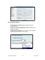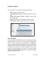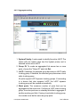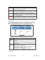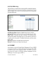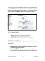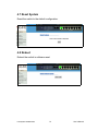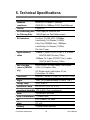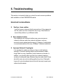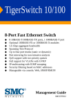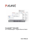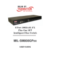
1
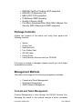
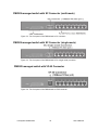
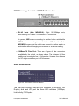
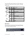
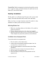
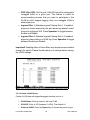
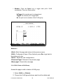
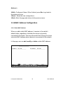
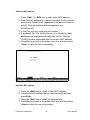
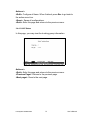
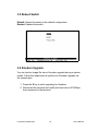
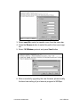
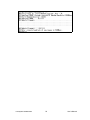
FriendlyNET® FM2008/2009
SNMP/Web Managed Switches
User’s Manual
Quick Start Guide
Follow these steps to install the switch:
1. Open the box and check the contents. See Chapter 1 for a complete list
of the items included with the switch.
2. Install the switch in an equipment or wall rack, or prepare it for desktop
placement.
3. Connect the power supply.
4. Connect network devices to the switch.
5. Refer to Chapters 4 and 5 for configuration and management
capabilities.
FriendlyNET FM2008/2009
2
User’s Manual
FriendlyNET FM2008/2009 SNMP/Web Managed Switches
User’s Manual
Asanté Technologies, Inc.
821 Fox Lane
San Jose, CA 95131
USA
SALES
800-662-9686 Home/Office Solutions
800-303-9121 Enterprise Solutions
408-435-8388
[email protected]
TECHNICAL SUPPORT
801-566-8991 Worldwide
801-566-3787 FAX
www.asante.com
[email protected]
Copyright © 2002 Asanté Technologies, Inc. Asanté and FriendlyNET are registered trademarks of Asanté Technologies, Inc. The Asanté
logo is a trademark of Asanté Technologies, Inc. All other names or marks are trademarks or registered trademarks of their respective
owners. All features and specifications are subject to change without prior notice.
Rev. A
FriendlyNET FM2008/2009
3
User’s Manual
Table of Contents
Quick Start Guide ................................................................................................... 2
1. Introduction......................................................................................................... 5
2. Hardware Description......................................................................................... 9
3. Console Management ...................................................................................... 15
4. Web-Based Management................................................................................. 55
5. Technical Specifications ................................................................................... 82
6. Troubleshooting................................................................................................ 83
FriendlyNET FM2008/2009
4
User’s Manual
1. Introduction
Thank you for purchasing the FM2008/2009 SNMP/Web Managed Switch.
The FM2008/2009 switches are compact desktop-sized switches that are
an ideal solution for the SOHO (Small Office or Home Office) network user.
They provide full wire-speed, Fast Ethernet switching that allows a
high-performance, low-cost connection. Each switch features
store-and-forward switching and can auto-learn and store source
addresses on an 8K-entry MAC address table.
Figure 1-1. The FriendlyNET FM2009 Switch
The FM2008/2009 both provide 8 switched, auto-sensing 10/100
Mbps RJ-45 Ethernet ports. Each switch will automatically detect the
speed of the device(s) connected to it, allowing the user to use both
10 and 100Mbps legacy devices. The 10Mbps bandwidth will
accommodate 10Mbps workgroup hubs while simultaneously
providing the 100Mbps bandwidth needed to accommodate
multimedia applications. In addition, each RJ-45 port supports Auto
MDI/MDI-X function.
The FM2009 switch also provides one 100Base-FX fiber port. Four
types of fiber connectors are available: SC, MT-RJ, VF-45
(multi-mode), and SC (single-mode). The fiber port can be used to
connect to a remote site up to 2 kilometers (multi-mode) or 15–60
kilometers (SC single-mode) away.
FriendlyNET FM2008/2009
5
User’s Manual
With its built-in Web-based Management, managing and configuring
the switch is easy: From cabinet management to port-level control
and monitoring, the user can visually configure and manage the
network via a web browser. Just click your mouse instead of typing
command strings. However, the switch can also be managed via
telnet, console, or SNMP management.
Features
• Conforms to IEEE 802.3, 802.3u, and 802.3x Ethernet
Standards
• 8x auto-sensing 10/100Mbps Ethernet RJ-45 ports
• Automatic MDI/MDI-X crossover for each 10BaseT/
100BaseTX port
• FM2009 only: 1 fixed 100Mbps fiber port (SC/SC single
mode/MT-RJ/VF-45 connector)
• Half-duplex mode for backpressure, and full-duplex for
flow control
• Store-and-forward switching architecture for abnormal
packet filtering
• Automatic address learning, address migration
• 8K-entry MAC address table
• 2Mbit memory buffer sharing
• Performs non-blocking full wire speed switching
• LED indicators for Power, 100Mbps, Link/Activity, Full
duplex
• 10 inch desktop-sized design
Intelligent Management Features
•
•
•
•
Web-based management
SNMP network management
Console and Telnet management
IEEE 802.1q Port Base VLAN and Tag VLAN up to 256
static VLANs, or up to 4094 dynamic VLANs
FriendlyNET FM2008/2009
6
User’s Manual
•
•
•
•
•
•
IEEE 802.1ad Port Trunking LACP supported
IEEE 802.1D Spanning Tree
MIB II (RFC1213) supported
IP Multicast, IGMP Snooping
Quality of Service (QoS)
Port Mirror, Broadcast Filter, Static MAC Address, Port
Security, MAC Filtering and GVRP supported
Package Contents
Unpack the contents of the switch and verify them against the
following checklist:
•
•
•
•
•
•
•
Switch
Power Cord
Rack Mount Kit
Four Rubber Feet
RS-232 Cable
Set-up Guide
User’s Manual (this document) on CD-ROM
If any item is missing or damaged, please contact your local dealer
immediately for service.
Management Methods
The switch series supports the following management methods:
• Console and Telnet Management
• Web-based Management
• SNMP Network Management
Console and Telnet Management
Console Management is done through the RS-232 Console Port.
Managing the switch in this method requires a direct connection
FriendlyNET FM2008/2009
7
User’s Manual
between the computer and the switch, while Telnet management is
done over the network. Once the switch is on the network, use Telnet
to log in and change the configuration.
Note: The default IP address of the switch is 192.168.0.1. Both the
default user name and the default password are root.
Web Based Management
The switch provides an embedded HTML web site residing in flash
memory. It offers advanced management features and allows users to
manage the switch from anywhere on the network through a standard
browser such as Microsoft Internet Explorer.
SNMP Network Management
SNMP (Simple Network Management Protocol) provides a means to
remotely manage network devices, and to monitor statistics, performance,
and security.
FriendlyNET FM2008/2009
8
User’s Manual
2. Hardware Description
This section describes the hardware of the FM2008 and 2009. (The
model shown is the FM2009. The FM2008 is identical, except that
there is no fiber uplink port.)
Front Panel
The front panel of the switch consists of 8 auto-sensing 10/100Mbps
Ethernet RJ-45 ports (automatic MDI/MDI-X), one 100Base-FX fiber
port, and the LED indicators.
FM2009 Managed Switch
Figure 2-1. The front panel of the switch
Four types of fiber connectors are available (FM2009 only): SC, SC
single-mode, MT-RJ, and VF-45.
FriendlyNET FM2008/2009
9
User’s Manual
FM2009 managed switch with SC Connector (multi-mode)
Figure 2-2. The front panel of the FM2009 with a SC connector
FM2009 managed switch with SC Connector (single-mode)
Figure 2-3. The front panel of the FM2009 with a SC (single mode) connector
FM2009 managed switch with VF-45 Connector
Figure 2-4. The front panel of the FM2009 with a VF45 connector
FriendlyNET FM2008/2009
10
User’s Manual
FM2009 managed switch with MT-RJ Connector
Figure 2-5. The front panel of the FM2009 with a MT-RJ connector
•
RJ-45 Ports (Auto MDI/MDI-X): Eight 10/100Mbps
auto-sensing for 10Base-T or 100Base-TX connections.
ports;
In general, MDI means connecting to another hub or switch while
MDI-X means connecting to a workstation or PC. Therefore, Auto
MDI/MDI-X means that the switch can connect to another switch or
workstation without changing non-crossover or crossover cabling.
• 100Base-FX Fiber Port: There are 4 types of fiber connectors
available for the switch, as shown above. The distance for fiber
cabling can be extended up to 2 kilometers. However, the distance
for SC single-mode fiber port is 60 kilometers.
LED Indicators
Figure 2-6. LED Indicators from the FM2009
The fiber port (FM2009) has two LED indicators (Link/Activity, Full
Duplex), and each UTP port has three LED indicators (100Mbps,
Link/Activity, Full Duplex).
FriendlyNET FM2008/2009
11
User’s Manual
The following table provides descriptions of the LEDs statuses and
meanings. These LEDs provide a real-time indication of systematic
operation status.
LED
Status Color
Power
100Mbps
On
Green Power On
On
Green The port is operating at 100Mbps
Off
On
Link/
Activity
The port is operating at 10Mbps, or no
device is attached
A valid link has been established on
Green
the port
Blinking Green
Off
On
Full
Duplex
Description
The port is receiving or transmitting
data
No device attached
The port is operating in full-duplex
Yellow mode. This LED is always lit on the
fiber port
Blinking Yellow Packet collision is occurring on the port
Off
Half-duplex mode or no device
attached
Table 2-1. The description of LED Indicators
Rear Panel
The console port and 3-pronged power plug are located at the rear
panel of the switch as shown in figure 2-7. The switch will work with
AC in the ranges 100–240V AC, 50–60Hz.
Figure 2-7. The rear panel of the switch
FriendlyNET FM2008/2009
12
User’s Manual
Console Port: Switch management can be done through the console
port. It requires a direct connection between the switch and an end
station (PC) via an RS-232 cable.
Desktop Installation
Set the switch on a sufficiently large flat space with a power outlet
nearby. The surface should be clean, smooth, level, and sturdy.
Make sure there is enough clearance around the switch to allow
attachment of cables, power cord and air circulation.
Attaching Rubber Feet
1. Make sure mounting surface on the bottom of the switch is
grease and dust free.
2. Remove adhesive backing from the rubber feet (supplied).
3. Apply the rubber feet to each corner on the bottom of the switch.
These footpads can prevent the switch from shock/vibration.
Installation Into an Equipment Rack
To mount the switch into an equipment rack:
1. Place the switch on a flat, stable surface.
2. Locate a rack-mounting bracket (supplied) and place it over the
mounting holes on one side of the unit.
3. Use the screws (supplied) to secure the bracket (with a Phillips
screwdriver).
4. Repeat the two previous steps on the other side of the unit.
5. Place the switch in the equipment rack.
6. Secure the switch by securing its mounting brackets onto the
equipment rack.
FriendlyNET FM2008/2009
13
User’s Manual
Important! Make sure the unit is supported until all of the mounting screws
for each bracket are secured to the equipment rack. Failure to do so could
cause the unit to fall, which may result in personal injury or damage to the
unit.
Equipment Rack Guidelines
•
•
•
Size: 10.0 x 5.2 x 1.5 inches
Ventilation: Ensure that the rack is installed in a room in which the
temperature remains below 40° C (104° F). Be sure that no
obstructions, such as other equipment or cables, block airflow to or
from the vents
Clearance: In addition to providing clearance for ventilation, ensure
that adequate clearance for servicing the switch from the front exists
Power On
Connect the power cord to the power socket on the rear panel of the
switch. The other side of power cord connects to the power outlet. The
internal power supply in the switch works with AC in the voltage
ranges 100-240VAC, frequency 50–60Hz.
Check the power indicator on the front panel to see if power is
properly supplied.
FriendlyNET FM2008/2009
14
User’s Manual
3. Console Management
This chapter explains how to configure console management via a
direct connection to the console port of the switch.
Console management involves the administration of the switch via a
direct connection to the RS-232 console port. This port is a female
DB-9 connector. From the main menu of the console program, user
has access to manage the functions of the switch.
Connecting a Terminal or PC to the Console Port
Figure 3-1. Connecting the switch to a terminal via an RS-232 cable
Use the supplied RS-232 cable to connect a terminal or PC to the
console port. The terminal or PC to be connected must support the
terminal emulation program.
After the connection between the switch and the PC is finished, turn
on the PC and run a terminal emulation program such as Hyper
Terminal to match the following default characteristics of the console
port:
FriendlyNET FM2008/2009
15
User’s Manual
Baud Rate: 9600
bps
Data Bits: 8
Parity: none
Stop Bit: 1
Control flow: None
Figure 3-2. Communication parameters settings
After entering the parameter settings, press the Enter key and the
Login screen for console management appears.
Console – Menu
The switch provides a serial interface to manage and monitor the
switch. The user can follow the Console Port Information provided by
the web interface to use Windows HyperTerminal program to connect
to the switch.
Type the user name and password to login. The default user name is
root and the default password is also root.
FriendlyNET FM2008/2009
16
User’s Manual
3.1 Main Menu
To move through each screen’s menu, use the Tab key or Backspace
bar to highlight an option, press Enter to select an option, and press
the Spacebar to toggle between configuration options.
The main menu contains the following options:
• Status and Counters: Displays the status of the switch
• Switch Static Configuration: Allows the user to configure the
switch
• Protocol Related Configuration: Allows the user to configure
supported protocols
FriendlyNET FM2008/2009
17
User’s Manual
• Reboot Switch: Restarts the system or resets switch to default
configuration
• Logout: Exits the menu line program
3.2 Status and Counters
From the main menu, select Status and Counters to configure the
following:
• Port Status
• Port Counters
• System Information
3.2.1 Port Status
This page displays the current status of each port.
• Type: Displays the port speed
• Enabled: Displays whether each port is enabled (“Yes”) or
disabled (“No”)
• Status: Displays each port’s link status; “Down” means there is
no link detected, and “Up” means there is a valid link detected
FriendlyNET FM2008/2009
18
User’s Manual
• Mode: Displays each port’s speed and duplex state
• FlowCtrl: Displays the flow control status of each port; “On”
indicates that flow control is enabled and “Off” indicates that it is
disabled
Actions->
Press the Tab or Backspace keys to choose action menu, and press
the Enter key to select an option.
<Quit>: Exits the port status page, and returns to the previous menu
<Previous Page>: Displays the previous page
<Next page>: Displays the next page
FriendlyNET FM2008/2009
19
User’s Manual
3.2.2 Port Counters
This page displays the current counter statistics for each port.
Actions->
Press the Tab or Backspace keys to choose action menu, and press
the Enter key to select an option.
<Quit>: Exits the port status page, and returns to the previous menu
<Reset All>: Sets all counters to 0
<Previous Page>: Displays the previous page
<Next page>: Displays the next page
3.2.3 System Information
This page displays the system information. Press the Esc key to
return to the main menu.
• System Description: Displays the name of the device
• MAC Address: Displays the unit’s MAC Address (the unique
hardware address assigned by the manufacturer)
• Firmware Version: Displays the firmware version
FriendlyNET FM2008/2009
20
User’s Manual
• Hardware Version: Displays the hardware version
• Default config value version: Displays the EEPROM version
3.3 Switch Static Configuration
From the main menu, select Switch Static Configuration to configure
the following options:
•
•
•
•
•
•
•
Administration Configuration
Port/Trunk Configuration
Port Mirroring Configuration
VLAN Configuration
Priority Configuration
MAC Address Configuration
Misc. Configuration
FriendlyNET FM2008/2009
21
User’s Manual
3.3.1 Administration Configuration
From the Switch Static Configuration menu, select Administration
Configuration to configure the following options:
•
•
•
•
Device Configuration
IP Configuration
Change Username
Change Password
FriendlyNET FM2008/2009
22
User’s Manual
3.3.1.1 Device Information
This page displays the device information. Use the action menu line to
change information.
Actions->
<Edit>: Allows the configuration of all items. When finished, press
Esc to return to the action menu line.
<Save>: Saves the new configuration.
<Quit>: Exits the Device Information page and returns to the previous
menu.
3.3.1.2 IP Configuration
From this page, the user can change the IP address from the default
IP address. Use the action menu line to enter the new IP setting.
FriendlyNET FM2008/2009
23
User’s Manual
Actions->
<Edit>: Configures all items. When finished, press Esc to go back to
the action menu line.
<Save>: Saves the new configuration.
<Quit>: Exits the IP Configuration page and returns to the previous
menu.
Note: You need to save and restart the computer after finishing IP
configuration.
FriendlyNET FM2008/2009
24
User’s Manual
3.3.1.3 Change Username
From this page the user can change the web management user
name.
3.3.1.4 Change Password
From this page the user can change the web management user
password.
FriendlyNET FM2008/2009
25
User’s Manual
3.3.2 Port/Trunk Configuration
From the Switch Static Configuration page, select Port/Trunk
Configuration to change each port’s status and to configure trunking
groups. Press the Space key to toggle between configuration options.
• Enabled: The user can disable or enable each port
• Auto Negotiate: The user can enable or disable auto
negotiation for each port
• Speed/Duplex Config: The user can set 100Mbps or 10Mbps
speed on ports 1-8 (port 9 is 100Mbps only), and set full-duplex
or half-duplex mode
• Flow Control: The user can enable or disable flow control
• Group: The user can set trunk groups for ports 1-8. There can
be up to four trunk groups
Actions->
<Quit>: Exits the port configuration page and returns to the previous
menu.
<Edit>: Configures all items. When finished, press Esc to go back to
the action menu line.
<Save>: Saves the new configurations.
FriendlyNET FM2008/2009
26
User’s Manual
<Previous Page>: Returns to the previous page.
<Next page>: Goes to the next page.
3.3.3 Port Mirroring Configuration
From the Switch Static Configuration page, select Port Mirroring
Configuration. Port mirroring is a method for monitoring traffic in
switched networks. Traffic through all the ports can be monitored by
one specific port. Press the Space key to toggle between the
configuration options:
• Port mirroring state: Use the space bar to toggle between
“Disabled” and “Enabled”
• Analysis Port: Select which port will act as a “sniffer” port to
monitor port traffic.
• Action: Select the ports to monitor. All monitored port traffic will
be copied to the “sniffer” port. You can select a maximum of 9
monitored ports in the switch. Under the Action option, you
may choose whether you want to monitor RX frames only or TX
frames only, or both.
Actions->
<Quit>: Exits the port monitoring configuration page and returns to
the previous menu.
FriendlyNET FM2008/2009
27
User’s Manual
<Edit>: Configures all items. When finished, press Esc to go back to
the action menu line.
<Save>: Saves the new configurations.
<Previous Page>: Returns to the previous page.
<Next page>: Goes to the next page.
3.3.4 VLAN Configuration
From the Switch Static Configuration page, select the VLAN
Configuration option to configure the following:
• VLAN Configure
• Create a VLAN Group
• Edit/Delete a VLAN Group
3.3.4.1 VLAN Configure
Use the console connection to enable VLANs on the switch. Select VLAN
Configure and Edit, then use the space bar to toggle between VLAN modes:
Disabled, Port-Based, 802.1Q, and 802.1QwithGVRP. When using 802.1Q
VLANs, enter the following values:
FriendlyNET FM2008/2009
28
User’s Manual
• PVID (Port VID): Set the port VLAN ID that will be assigned to
untagged traffic on a given port. This feature is useful for
accommodating devices that you want to participate in the
VLAN but don’t support tagging. Only one untagged VLAN is
allowed per port
• Ingress Filter 1: Matches Ingress Filtering Rule 1. If enabled,
drops any frame received by the port whose tag doesn’t match
the port’s configured VID. Press Spacebar to toggle between
Enable and Disable
• Ingress Filter 2: Matches Ingress Filtering Rule 2. If enabled,
drops any frame without a VLAN tag. Press Spacebar to toggle
between Enable and Disable
Important! Enabling either of these filters may disrupt communication
through the switch. Please double-check your settings before saving
the VLAN settings.
3.3.4.2 Create a VLAN Group
Create a VLAN and add tagged/untagged member ports to it.
•
•
•
VLAN Name: Enter a name for the new VLAN
VLAN ID: Enter a VID (between 2~4094). The default is 1
Protocol VLAN: Press the Space key to choose the protocol type
FriendlyNET FM2008/2009
29
User’s Manual
• Member: Press the Space key to toggle each port’s VLAN
membership. There are three options:
UnTagged: the member port is untagged port
Tagged: the member port is tagged port
No: the port is not a member of the VLAN group
Actions->
<Quit>: Exits this page and returns to the previous menu.
<Edit>: Configures all items. When finished, press Esc to go back to
the action menu line.
<Save>: Saves the new configurations.
<Previous Page>: Returns to the previous page.
<Next page>: Goes to the next page.
3.3.4.3 Edit / Delete a VLAN Group
Access this page to edit or delete a VLAN group.
1. Select <Edit> or <Delete>.
2. Choose the VLAN group that you want to edit or delete and
FriendlyNET FM2008/2009
30
User’s Manual
then press Enter.
3. Modify the options as desired, or add or remove member ports
as desired.
4. After completing the desired changes to the VLAN, press
<Save> to save the new configuration.
Note: The default VLAN cannot be deleted, nor can the VLAN Name
or VLAN ID be modified.
FriendlyNET FM2008/2009
31
User’s Manual
3.3.5 Priority Configuration
There are 7 priority levels that map traffic to two queues. The High/Low
Queue Service Ratio (H:L) allows the user to select the ratio of high priority
packets to low priority packets processed by the switch.
First In First Out: The packets are sent out in the order they were
received.
High to Low: High priority packets are sent before low priority
packets.
Ratio: The user may select the precedence given to packets in the
switch's high-priority queue. These options represent the number of
high priority packets sent before one or more low priority packets are
sent. For example, a ratio of 5:2 means that the switch sends 5 high
priority packets before sending 2 low priority packets.
FriendlyNET FM2008/2009
32
User’s Manual
Actions->
<Edit>: Configure all items. When finished, press Esc to go back to
the action menu line.
<Save>: Saves the new configurations.
<Quit>: Exits this page and returns to the previous menu.
3.3.6 MAC Address Configuration
3.3.6.1 Static MAC Address
When you add a static MAC address, it remains in the switch's
address table, regardless of whether the device is physically
connected to the switch. This saves the switch from having to re-learn
a device's MAC address when a device is reconnected to the network.
In this page user can add, modify or delete a static MAC address.
FriendlyNET FM2008/2009
33
User’s Manual
Add static MAC address
1. Press <Add> --> <Edit> key to add a static MAC address.
2. Enter the MAC address of a device from which the port should
permanently forward traffic regardless of the device’s network
activity. Enter the address without separators (e.g.
000094abcdef)
3. In the Port num item, enter the port number.
4. If tag-based (802.1Q) VLANs are set up on the switch, static
addresses are associated with individual VLANs. Type the
VLAN ID number associated with the device’s MAC address.
5. Press Esc to go back to the action menu line, and then select
<Save> to save the new configuration.
Edit static MAC address
1. Press the <Edit> key to modify a static MAC address.
2. Choose the MAC address that you want to modify and then
press Enter.
3. Press the <Edit> key to modify the desired items.
4. Press Esc to go back to the action menu line, and then select
<Save> to save the new configuration.
FriendlyNET FM2008/2009
34
User’s Manual
Delete static MAC address
1. Press the <Delete> key to delete a static MAC address.
2. Choose the MAC address that you want to delete and then
press Enter.
3. After deleting the static MAC address, press <Save> to have
the changes take effect.
FriendlyNET FM2008/2009
35
User’s Manual
3.3.6.2 Filter MAC Address
From this screen, add, edit, or delete filter MAC addresses.
3.3.7 Miscellaneous Configuration
3.3.7.1 Port Security
By default, the port security feature is disabled for each port to allow for
address learning. When port security is enabled, the port will only accept
incoming packets from a known static MAC address. The user can enable
port security on a port, and then use the Static MAC Address page to define
a list of MAC addresses that can use the secure port.
FriendlyNET FM2008/2009
36
User’s Manual
Select <Edit> to enable or disable the port security.
Press the Space bar to toggle between enabled and disabled on each
port.
Press Esc to go back to the action menu line, and then select <Save>
to save the new configuration.
3.3.7.2 MAC Age Interval
From this screen, you may enter the time (in seconds) that an inactive
MAC address remains in the switch’s address table. The valid range
is 300–765 seconds. The default is 300 seconds.
FriendlyNET FM2008/2009
37
User’s Manual
Actions->
<Edit>: Configure all items. When finished, press Esc to go back to
the action menu line.
<Save>: Saves the new configurations.
<Quit>: Exits this page and returns to the previous menu.
3.3.7.3 Broadcast Storm Filtering
From this page you may configure the broadcast storm filter. Press
<Edit> to proceed to configure the broadcast storm filter.
Press the Spacebar to choose the threshold value. This is the
percentage of total traffic that may be broadcast before the filter takes
effect. Valid threshold values are 5%, 10%, 15%, 20%, 25% and NO.
Actions->
<Edit>: Configure all items. When finished, press Esc to go back to
the action menu line.
<Save>: Saves the new configurations.
<Quit>: Exits this page and returns to the previous menu.
FriendlyNET FM2008/2009
38
User’s Manual
3.3.7.4 Max bridge transmit delay bound
• Max bridge transmit delay bound: Limits the packet queue
time in the switch. If enabled, the packets will be dropped from
the queue after the time has expired. Press the Space bar to
set the time. The options are 1 second, 2 seconds, 4 seconds
and off. The default is 1 second
• Enable Delay Bound: Limits the low priority packets’ queuing
time in the switch. If enabled, the low priority packets that stay
in the switch past the Max Delay Time will be sent. Press the
Space bar to enable or disable this function
Note: Make sure that Max bridge transit delay bound control is
enabled before enabling Delay Bound.
• Max Delay Time: Sets the time that low priority packets may
queue in switch. The valid range is 1–255 ms.
NOTE: Make sure that “Max bridge transit delay bound control” is
enabled before enabling Delay Bound.
FriendlyNET FM2008/2009
39
User’s Manual
Actions->
<Edit>: Configure all items. When finished, press Esc to go back to
the action menu line.
<Save>: Saves the new configurations.
<Quit>: Exits this page and returns to the previous menu.
3.4 Protocol Related Configuration
3.4.1 Spanning Tree Protocol (STP)
3.4.1.1 STP Enable
On this screen you may enable or disable the Spanning Tree function.
Press the Space bar to toggle between Enable and Disable.
FriendlyNET FM2008/2009
40
User’s Manual
3.4.1.2 System Configuration
On the left of this screen, you can view the Root Bridge Information.
On the right, you can configure new values for the STP parameters.
Bridge Priority
Setting the Bridge Priority to a low value will increase the likelihood that the
current bridge will become the root bridge. If the current bridge is located
physically near the center of your network, you may wish to decrease the
Bridge Priority from its default value of 32768 to make it become the root
bridge. If the current bridge is near the edge of your network, it is best to
leave the value of the Bridge Priority at its default setting.
Hello Time
This is the time period between BPDUs transmitted by each bridge. The
default setting is 3 seconds.
Maximum Age
Each bridge should receive regular configuration BPDUs from the direction
of the root bridge. If the maximum age timer expires before the bridge
receives another BPDU, it assumes that a change in the topology has
FriendlyNET FM2008/2009
41
User’s Manual
occurred, and it begins recalculating the spanning tree. The default setting
for Maximum Age is
15 seconds.
Forward Delay
After a recalculation of the spanning tree, the Forward Delay parameter
regulates the delay before each port begins transmitting traffic. If a port
begins forwarding traffic too soon (before a new root bridge has been
selected), the network can be adversely affected. The default value for
Forward Delay is 5 seconds.
Note: The above parameters (Hello Time, Maximum Age and Forward
Delay) are constrained by the following formula:
(Hello Time + 1) <= Maximum Age <= 2 x (Forward Delay – 1)
In general, reducing the values of these timers will make the spanning tree
react faster when the topology changes, but may cause temporary loops as
the tree stabilizes in its new configuration. Increasing the values of these
timers will make the tree react more slowly to changes in topology, but will
make an unintended reconfiguration less likely. All of the bridges on the
network will use the values set by the root bridge. It is only necessary to
reconfigure that bridge if you wish to change the parameters.
FriendlyNET FM2008/2009
42
User’s Manual
3.4.1.3 Per-port Configuration
PortState: View the spanning tree status for each port.
PathCost: Port path cost is the spanning tree parameter that assigns a
cost factor to each port. The lower the assigned port path cost is, the more
likely that port will be accessed. The default port path cost for a 10Mbps or
100Mbps port is the result to the equation:
Path cost = 1000/LAN speed (in Mbps)
Therefore, for ports operating at 10Mbps, the default port path cost is 100.
For ports operating at 100Mbps, it is 10. If you change the value, you
need to restart the switch for the change to take effect.
Priority: The port priority is a spanning tree parameter that ranks each port,
so that if two or more ports have the same path cost, the STP selects the
path with the highest priority (the lowest numerical value). By changing the
priority of a port, you can make it more, or less, likely to become the root
port. The default value is 128, and the value range is 0 – 255. If you
change the value, you need to restart the switch for the change to take
effect.
FriendlyNET FM2008/2009
43
User’s Manual
3.4.2 SNMP
Use this page to define management stations as trap managers and
to enter SNMP community strings. You can also define a system
name, location, and contact person for the switch.
4.4.2.1 System Options
Select <Edit> to enter the information, and then select <Save> to
have the changes take effect.
FriendlyNET FM2008/2009
44
User’s Manual
System Name: Enter a name to be used for the switch.
System Contact: Enter the name of contact person or organization.
System Location: Enter the location of the switch.
3.4.2.2 Community Strings
Use this page to enter SNMP community strings.
Community Name: Enter the name of the current string.
Write Access: Designate the access rights of the current string.
• Restricted: Read-only enables requests accompanied by this
string to retrieve MIB object information
• Unrestricted: Read-Write enables requests accompanied by
this string to retrieve MIB object information and to set MIB
objects to a new value
FriendlyNET FM2008/2009
45
User’s Manual
Actions->
<Add>: Creates community strings.
<Edit>: Modifies items. When finished, press Esc to go back to the
action menu line.
<Delete>: Deletes a community string. Press <Save> to have your
changes take effect.
<Save>: Saves the new configurations.
<Quit>: Exits this page and returns to the previous menu.
3.4.2.3 Trap Managers
A trap manager is a management station that receives traps, the
system alerts generated by the switch. If no trap manager is defined,
no traps are issued. Create a trap manager by entering the IP address
of the station and a community string.
FriendlyNET FM2008/2009
46
User’s Manual
Actions->
<Add>: Creates a trap manager.
<Edit>: Modifies all items. When finished, press Esc to go back to the
action menu line.
<Delete>: Deletes a trap manager. Press <Save> to have your
changes take effect.
<Save>: Saves all the new configurations.
<Quit>: Exits this page and returns to the previous menu.
FriendlyNET FM2008/2009
47
User’s Manual
3.4.3 GVRP
On this page you can enable or disable the GVRP (GARP VLAN
Registration Protocol) support.
Press the Space bar to toggle between Enabled/Disabled.
Actions->
<Edit>: Configure all items. When finished, press Esc to go back to
the action menu line.
<Save>: Saves all new configurations.
<Quit>: Exits this page and returns to the previous menu.
FriendlyNET FM2008/2009
48
User’s Manual
3.4.4 Link Aggregation Control Protocol (LACP)
3.4.4.1 Aggregator Setting
Group: Displays the trunk group ID.
LACP: Press the Space bar to enable or disable LACP (Link
Aggregation Control Protocol) support. If enabled, the group is a
LACP static trunking group. If disabled, the group is a local static
trunking group.
LACP Work Port Num: The maximum number of ports that can be
aggregated at the same time. If using the LACP static trunking group,
the extra ports are on standby and able to aggregate if a work port
fails. If using a local static trunking group, the number must be the
same as the number of group ports.
Note: Before setting LACP support, you first have to set trunking
groups in the Port/Trunk Configuration page.
FriendlyNET FM2008/2009
49
User’s Manual
Actions->
<Edit>: Configure all items. When finished, press Esc to go back to
the action menu line.
<Save>: Saves all configurations.
<Quit>: Exits this page and returns to the previous menu.
3.4.4.2 State Activity
Active: The port automatically sends LACP protocol packets.
Passive: The port does not automatically send LACP protocol
packets, but responds only if it receives LACP protocol packets from
another device.
FriendlyNET FM2008/2009
50
User’s Manual
Actions->
<Edit>: Configure all items. When finished, press Esc to go back to
the action menu line.
<Save>: Saves all configurations.
<Quit>: Exits this page and returns to the previous menu.
3.4.4.3 LACP Status
In this page, you may view the trunking group information.
Actions->
<Quit>: Exits this page and returns to the previous menu.
<Previous Page>: Returns to the previous page.
<Next page>: Goes to the next page.
FriendlyNET FM2008/2009
51
User’s Manual
3.5 Reboot Switch
Default: Resets the switch to the default configuration.
Restart: Reboots the switch.
3.6 Xmodem Upgrade
You can load an image file via an Xmodem upgrade during a system
restart. Follow the steps below to perform an Xmodem upgrade via
the console port.
1. Press the X key to start upgrading for Xmodem.
2. Disconnect the terminal and modify the baud rate to 57600bps,
then reconnect to the terminal.
FriendlyNET FM2008/2009
52
User’s Manual
3. Select send file under the transfer menu from the menu bar.
4. Press the Browse button to select the path to the new image
file.
5. Select 1K XModem protocol and press Send button.
6. After successfully upgrading the new firmware, please modify
the baud rate setting of your terminal program to 9600bps.
FriendlyNET FM2008/2009
53
User’s Manual
FriendlyNET FM2008/2009
54
User’s Manual
4. Web-Based Management
This section introduces the configuration and functions of the
web-based management of the switch.
The FM2009 provides an embedded HTML website residing in flash
memory that allows users to manage the switch from anywhere on the
network using a standard web browser.
Note: For those who use Windows 2000 and have installed Service
Pack#2, the web management function may have display problems if
the IE version is 5.5 or older.
Web Management Function
1. The web management function uses a web browser to manage
and monitor the switch. The switch has the following default
values:
IP Address:
User Name:
Password:
192.168.0.1
root
root
If you need to change the IP Address immediately, you can use the
console mode to modify it.
2. Launch your web browser and enter http://192.168.0.1 in the URL
field. When prompted, type the user name and password and click
OK.
FriendlyNET FM2008/2009
55
User’s Manual
4.1 Home Page
After entering the user name and password, you will come to the Home
page, as shown below. The following pages may be accessed from the
Home page:
•
•
•
•
•
•
•
Port Status
Port Statistics
Administrator
TFTP Update Firmware
Configuration Backup
Reset System
Reboot
FriendlyNET FM2008/2009
56
User’s Manual
4.2 Port Status
The following information is displayed in the Port Status page:
• State: Displays each port’s status; off or on depending on the
user’s setting
• Link Status: Displays each port’s link status (up or down)
• Auto Negotiation: Displays each port’s auto-negotiation mode
• Speed status: Displays each port’s link speed: Port 1-8 are
10/100Mbps, Port 9 is 100 Mbps only
• Duplex status: Displays each port’s duplex mode (full or half)
• Flow control: Displays each port’s flow control status (On is
enabled, Off is disabled)
• Config: Displays the current configuration setting
• Actual: Displays the negotiation result
FriendlyNET FM2008/2009
57
User’s Manual
4.3 Port Statistics
The Port Statistics page provides the current status of the unit.
4.4 Administrator
The management functions include:
IP Address, Switch Settings, Console Port Information, Port Controls,
Link Aggregation, Filter Database, VLAN Configuration, Spanning
Tree, Port Mirror, SNMP, Security Manager, TFTP Update Firmware,
Configuration Backup, Reset System and Reboot.
4.4.1 IP Address
From this page, you can change the IP Address from the default value
(recommended). Fill in the new values, then click the Apply button.
You must reset switch and then enter the new IP address into the
browser’s URL window to access the web management interface. You
may also need to change your computer’s IP address to the same
network as the switch’s new IP address.
FriendlyNET FM2008/2009
58
User’s Manual
4.4.2 Switch Settings
4.4.2.1 Basic
The Basic Switch Settings page displays the current information of the
switch. Click the Basic button on the Switch Settings page to display the
following information:
• Description: Displays the name of the device
• MAC Address: Displays the unique hardware address
assigned by the manufacturer
• Firmware Version: Displays the current firmware version
• Hardware Version: Displays the hardware version
• Default config value version: Displays the Default config
value version
FriendlyNET FM2008/2009
59
User’s Manual
4.4.2.2 Advanced
From the Switch Settings page, click the Advanced button to display
or configure the following information:
• MAC Address Age-out Time: Enter the number of seconds
that an inactive MAC address can remain in the switch's
address table. The valid range is 300–765 seconds, the default
is 300 seconds
• Max bridge transit delay bound control: Limits the packets’
queuing time in switch. If enabled, the packets in the queue will
be dropped when the time expires. The valid values are 1
second, 2 seconds, 4 seconds and off (default is 1 second)
• Broadcast Storm Filter: To configure broadcast storm control,
enable it and set the upper threshold for individual ports. The
threshold is the percentage of the port's total bandwidth used
by broadcast traffic. When broadcast traffic for a port rises
above the threshold you set, broadcast storm control becomes
active. The valid threshold values are 5%, 10%, 15%, 20%,
25% and off
.
FriendlyNET FM2008/2009
60
User’s Manual
Priority Queue Service settings:
• First Come First Served: The sequence of packets sent
depends on their order of arrival
• All High before Low: All high priority packets are sent before
any low priority packets
• Weighted Round Robin (WRR): Select the preference given
to packets in the switch's high-priority queue. These options
represent the number of high priority packets sent before one
low priority packet is sent. For example, a 5:2 ratio means that
the switch sends 5 high priority packets before sending 2 low
priority packets
• Enable Delay Bound: Limit the low priority packets queuing
time in switch. Default Max Delay Time is 255ms. If the low
priority packet stays in switch longer than the Max Delay Time,
it will be sent. The valid range is 1–255 ms
Note: Make sure that Max bridge transit delay bound control is
enabled before checking the Enable Delay Bound box
• QoS Policy: High Priority Levels: Select which priority levels
are mapped to the high priority output queue.
FriendlyNET FM2008/2009
61
User’s Manual
Protocol Enable Settings:
• Enable Spanning Tree Protocol: Enabled by default
(recommended)
• Enable Internet Group Multicast Protocol: IGMP protocol
enabled by default
• VLAN Operation Mode: Select Port Based, 802.1Q without
GVRP, 802.1Q with GVRP, or No VLAN
FriendlyNET FM2008/2009
62
User’s Manual
GVRP (GARP [Generic Attribute Registration Protocol] VLAN
Registration Protocol)
GVRP allows automatic VLAN configuration between the switch and
nodes. If the switch is connected to a device with GVRP enabled, you
can send a GVRP request using the VID of a VLAN defined on the
switch; the switch will automatically add that device to the existing
VLAN.
4.4.3 Console Port Information
The console is a standard UART interface used to communicate with
the serial port. You may use Windows HyperTerminal or a similar
program to link to the switch. From this page, you may view or
configure the desired parameters for your console connection:
Bits per seconds: 9600
Data bits: 8
Parity: none
Stop Bits: 1
Flow control: none
FriendlyNET FM2008/2009
63
User’s Manual
4.4.4 Port Controls
From this page you can configure the following parameters:
• State: Disable or enable each port
• Auto Negotiation: Disable or enable auto negotiation for each
port
• Speed: Set port speed (100Mbps or 10Mbps) on ports 1-8; port
9 is 100Mbps only
• Duplex: Set full-duplex or half-duplex mode for each port
• Flow Control: Enable or disable flow control for each port
4.4.5 Trunking
Trunking provides a standardized means for exchanging information
between multiple devices on a link. This allows their Link Aggregation
Control to reach an agreement on the identity of the Link Aggregation
Group, move the link to that Link Aggregation Group, and enable its
transmission and reception functions in an orderly manner. Trunk up
to eight consecutive ports into a single dedicated connection. This
feature can expand bandwidth to a device on the network. LACP
operation requires full-duplex mode. For more detailed information,
please refer to IEEE 802.3ad.
FriendlyNET FM2008/2009
64
User’s Manual
4.4.5.1 Aggregator setting
1. System Priority: A value used to identify the active LACP. The
switch with the lowest value has the highest priority and is
selected as the active LACP.
2. Group ID: To create an aggregated link across two or more
ports, choose the "Group ID" and click Get.
3. LACP: If enabled, the selected group becomes an LACP static
trunking group. If disabled, the selected group becomes a local
static trunking group.
All ports support LACP dynamic trunking groups. If connecting
to a device that also supports LACP, the LACP dynamic
trunking group will be created automatically.
4. Work ports: The maximum number of ports that can be
aggregated at the same time. If utilizing a LACP static trunking
group, the extra ports are on standby and able to aggregate if
another working port fails. If using a local static trunking group,
the number must be the same as group ports.
FriendlyNET FM2008/2009
65
User’s Manual
5. Select the ports to join the trunking group
6. If LACP is enabled, you can configure the LACP Active/Passive
status on each port.
7. Click Apply.
4.4.5.2 Aggregator Information
When setting the LACP aggregator, you can view the related
information by clicking Aggregator Information.
4.4.5.3 State Activity
Click on State Activity to configure each port to automatically send LACP
protocol packets.
Active (Status box selected): Check the box in each port to have that
port automatically send the LACP protocol packets.
Passive (Status box unselected): With the box unchecked, the port
will not automatically send the LACP protocol packets, and responds
only if it receives LACP protocol packets from the opposite device.
A link having either two active LACP ports or one active port can
perform dynamic LACP trunking.
FriendlyNET FM2008/2009
66
User’s Manual
A link that has two passive LACP ports will not perform dynamic LACP
trunking because both ports are waiting for a LACP protocol packet
from the opposite device.
If you select active LACP, the active status will be created
automatically when you select the trunking port.
4.4.6 Filter Database
4.4.6.1 IGMP Snooping
The switch supports IP multicasting. Enable the IGMP protocol on the web
interface’s Switch Setting/Advanced page, and then click the IGMP
Snooping button to view the multicast group, VID and member port. IP
FriendlyNET FM2008/2009
67
User’s Manual
multicast addresses range from 224.0.0.0 through 239.255.255.255.
The Internet Group Management Protocol (IGMP) is an internal protocol of
the Internet Protocol (IP) suite. IP manages multicast traffic by using
switches, routers, and hosts that support IGMP. Enabling IGMP allows the
ports to detect IGMP queries and report packets and manage IP multicast
traffic through the switch. IGMP has three types of messages, as described
in the table below:
Message
Description
A message sent from the IGMP router or switch asking for a response from
Query
each host belonging to the multicast group.
A message sent by a host to the IGMP router or switch to indicate that the host
Report
wants to be or is a member of a given group indicated in the report message.
A message sent by a host to the IGMP router or switch to indicate that the host
Leave
has quit to be a member of a specific multicast group.
Group
4.4.6.2 Static MAC Address
Click the Static MAC Addresses button to view or configure the static
addresses currently defined on the switch.
When you add a static MAC address, it remains in the switch's
address table, regardless of whether the device is physically
FriendlyNET FM2008/2009
68
User’s Manual
connected to the switch. This saves the switch from having to re-learn
a device's MAC address when the device is active on the network
again.
To add a static MAC address:
1. From the main menu, click Administrator, and then click Filter
Database.
2. Click Static MAC Addresses. In the MAC address box, enter
the MAC address to and from which the port should
permanently forward traffic, regardless of the network activity of
the device.
3. In the Port Number box, select a port number.
4. If tag-based (IEEE 802.1Q) VLANs are set up on the switch,
static addresses are associated with individual VLANs. Type
the VID (tag-based VLANs) associated with the MAC address.
5. Click Add.
4.4.6.3 Port Security
Click the Port Security button to enable security. A port in security
mode will be “locked” to traffic from devices whose MAC addresses
are not in the Static MAC Addresses table. Only incoming packets
with Source MAC already existing in the address table can be
forwarded normally. First, disable the port from learning any new MAC
addresses by checking the Enable Security box, and then use the
static MAC addresses screen to define a list of MAC addresses that
can use the secure port. After you are finished entering the settings,
click Submit to apply the changes to this page.
FriendlyNET FM2008/2009
69
User’s Manual
4.4.6.4 MAC Address Filtering
MAC address filtering allows the switch to drop unwanted traffic. Traffic is
filtered based on the source or destination addresses. For example, if your
network is congested because of high utilization from one MAC address,
you can filter all traffic transmitted from that MAC address, restoring
network flow while you troubleshoot the problem.
To add a MAC address filter
1. From the main menu, click Administrator, then click Filtering
Database.
FriendlyNET FM2008/2009
70
User’s Manual
2. Click MAC Filtering.
3. Click Add.
4. In the MAC Address box, type the MAC address (without hyphens) to
filter.
5. Select the port that will filter traffic from this address.
6. If port-based or tag-based VLANs are configured on the switch, type
the name or VID of the VLAN to use the filter.
7. Click Apply.
4.4.7 VLAN configuration
A Virtual LAN (VLAN) is a logical network grouping that limits the broadcast
domain. It allows you to isolate network traffic so only members of the same
VLAN receive traffic from other VLAN members. Creating a VLAN from a
switch is logically equivalent to reconnecting a group of network devices to
another Layer 2 switch. However, all the network devices are still plugged
into the same switch physically. The switch supports port-based and
protocol-based VLANs. In the default configuration, VLAN support is
enabled and all ports on the switch belong to the default VLAN, whose
VLAN ID (VID) is 1.
Note: The default VLAN cannot be deleted.
Port-based VLANs (IEEE 802.1Q VLAN)
This feature is an IEEE 802.1Q specification standard. Therefore, it is
possible to create a VLAN across devices from different switch vendors.
IEEE 802.1Q VLAN uses a technique to insert a “tag” into the Ethernet
frames. The tag contains a VLAN Identifier (VID) that indicates the VLAN
numbers.
FriendlyNET FM2008/2009
71
User’s Manual
Protocol-based VLANs
In order for an end station to send packets to different VLANs, it itself
has to be capable of tagging packets it sends with VLAN tags, or it
must be attached to a VLAN-aware bridge that is capable of
classifying and tagging the packets with different VLAN IDs, based on
not only on the default PVID but also other information about the
packet, such as the protocol.
4.4.7.1 Basic
Create a VLAN and add tagged member ports to it.
1. From the main menu, click Administrator -- VLAN
Configuration.
2. Click Add.
3. Type a name for the new VLAN.
4. Type a VID (between 2-4094). The default is 1.
5. From the Available Ports box, select ports to add to the switch
and click Add.
6. Click Apply.
FriendlyNET FM2008/2009
72
User’s Manual
4.4.7.2 Port VID
Configure port VID settings
From the main Tag-based (IEEE 802.1Q) VLAN page, click Port VID
Settings.
Port VID (PVID)
From this page, you can set the Port VLAN ID that will be assigned to
untagged traffic on a given port. For example, if port 9's Default PVID
is 100, all untagged packets on port 9 will belong to VLAN 100. The
default setting for all ports is VID 1.
This feature is useful for accommodating devices that you want to
participate in the VLAN but that don't support tagging. Only one
untagged VLAN is allowed per port.
FriendlyNET FM2008/2009
73
User’s Manual
Ingress Filtering
Ingress filtering lets frames belonging to a specific VLAN to be
forwarded if the port belongs to that VLAN. The switch has two
ingress filtering rules, as follows:
Ingress Filtering Rule 1: Forward only packets with a VID matching
this port's configured VID.
Ingress Filtering Rule 2: Drop untagged Frames.
4.4.8 Spanning Tree
The Spanning Tree Protocol (STP) is a standardized method (IEEE 802.1D)
for avoiding loops in switched networks. When STP is enabled, it ensures
that only one path at a time is active between any two nodes on the network.
You can enable Spanning Tree Protocol on the web interface Switch Setting
Advanced item by selecting Enable Spanning Tree protocol. It is
recommended that you enable STP on all switches to ensure a single active
path on the network.
FriendlyNET FM2008/2009
74
User’s Manual
1. You can view Spanning Tree information about the Root
Bridge, as in the following screen:
2. You can view Spanning Tree port status, as in the following
screen:
3. You can configure new values for the STP parameters, and
then click the Apply button to modify.
FriendlyNET FM2008/2009
75
User’s Manual
Parameter
Description
You can change the priority value used to identify the root bridge. The
Priority bridge with the lowest value has the highest priority and is selected as the
root. Enter a number 1 through 65535.
You can change the Max Age value, the number of seconds a bridge
Max Age
waits without receiving Spanning Tree Protocol configuration messages
before attempting a reconfiguration. Enter a number 6 through 40.
Hello Time You can change the Hello time value, the number of seconds between
the transmission of Spanning Tree Protocol configuration messages.
Enter a number 1 through 10.
You can change the forward delay time, the number of seconds a port
Forward
waits before changing from its Spanning Tree Protocol learning and
Delay time
listening states to the forwarding state. Enter a number 4 through 30.
Note: Only users familiar with the operation of Spanning Tree Protocol should change
these values.
4. The following parameters can be configured on each port.
Click the Apply button to have the changes take effect.
Parameter
Description
You can make a port more or less likely to become the root port, by
Port
adjusting the priority setting. The rage is 0-255, with the default
Priority
setting is 128.
The lower the number the higher priority the port is given, making it
more likely to be the root port. If you change the value, you must
reboot the switch.
Specifies the path cost of the port that the switch uses to determine
Path Cost which ports are the forwarding ports.
The port with the lowest path cost becomes the forwarding port. The
rage is 1-65535 and default value base on IEEE802.1D
10Mb/s = 50-600
100Mb/s = 10-60
If you change the value, you MUST reboot the switch.
Note: Only users familiar with the operation of Spanning Tree Protocol should change
these values.
FriendlyNET FM2008/2009
76
User’s Manual
4.4.9 Port Mirroring
The Port Mirror is a method for monitoring traffic in switched networks.
Traffic through the ports can be monitored by one specific port. That is,
traffic that goes into or out of the monitored ports will be duplicated
into the analysis port.
Port Mirroring State: Enable or disable the port mirror function.
Analysis Port: Select which port will copy all monitored ports’ traffic.
Mirror Ports: The ports you want to monitor. All monitored ports’
traffic will be copied to the analysis port. You can select a maximum of
9 monitor ports in the switch. To disable this function, set the monitor
port to none.
Monitor Rx: Monitor received frames from the port.
Monitor Tx: Monitor sent frames from the port.
4.4.10 SNMP
Any workstation running the Simple Network Management Protocol (SNMP)
can manage the switch, provided the Management Information Base (MIB)
is installed correctly on the management station. The SNMP is a protocol
that governs the transfer of information between management and the
SNMP agent. The switch supports SNMP v1.
FriendlyNET FM2008/2009
77
User’s Manual
Use this page to define management stations as trap managers and
to enter SNMP community strings. You can also define a name,
location, and contact person for the switch. Fill in the system options
data, and then click Apply to update the changes on this page.
4.4.10.1 System Options
• Name: Enter a name to be used for the switch
• Location: Enter the location of the switch
• Contact: Enter the name of a person or organization
4.4.10.2 Community Strings
Community strings serve as passwords and can be entered as one of
the following:
• Read only (RO): Enables requests accompanied by this string
to display MIB-object information
• Read-write (RW): Enables requests accompanied by this
string to display MIB-object information and to set MIB objects
FriendlyNET FM2008/2009
78
User’s Manual
4.4.10.3 Trap Manager
A trap manager is a management station that receives traps, the system
alerts generated by the switch. If no trap manager is defined, no traps are
issued. Create a trap manager by entering the IP address of the station and
a community string.
4.4.11 Security Manager
Use this page to change the web management user name and
password.
Default User name: root
Default Password: root
4.5 TFTP Update Firmware
TFTP is the Trivial File Transfer Protocol.
Use this page to set the TFTP server IP address (the new image code must
have been saved to the TFTP server). Enter the file name and click Apply.
The switch will download the new flash image from the server.
FriendlyNET FM2008/2009
79
User’s Manual
4.6 Configuration Backup
4.6.1 TFTP Restore Configuration
Use this page to set TFTP server address. You can restore the EEPROM
value from here, but you must put the back image in TFTP server, the switch
will download the back flash image.
4.6.2 TFTP Backup Configuration
Use this page to set the TFTP server IP address. You can save the
current EEPROM value from here, then go to the TFTP restore
configuration page to restore the EEPROM value.
FriendlyNET FM2008/2009
80
User’s Manual
4.7 Reset System
Reset the switch to the default configuration.
4.8 Reboot
Reboot the switch in software reset.
FriendlyNET FM2008/2009
81
User’s Manual
5. Technical Specifications
Standards
Compliance
IEEE 802.3 10Base-T Ethernet,
Protocol
CSMA/CD
IEEE 802.3u 100Base-TX/FX Fast Ethernet
Max Forwarding and 14,880 pps per Ethernet port
Max Filtering Rate
148,800 pps per Fast Ethernet port
LED Indicators
Per Port: (10/100 UTP): 100Mbps,
Link/Activity, Full Duplex (3 LEDs)
Fiber Port (FM2009 only): 100Mbps,
Link/Activity, Full Duplex (3 LEDs)
Per Unit: Power
Copper Network
Cables
10Base-T: 2-pair UTP/STP Cat. 3, 4, 5 cable
EIA/TIA-568 100-ohm (100m)
100Base-TX: 2-pair UTP/STP Cat. 5 cable
EIA/TIA-568 100-ohm (100m)
Fiber Link Max.
Distance (FM2009
only)
SC/MT-RJ/VF-45 Multi-mode: Half-duplex:
412m, Full-duplex: 2Km
Dimensions
254mm x 132mm x 37mm (10.0 x 5.2 x 1.5 in.)
Weight
1080 ±20 g (approximately 2.4 lbs ± 1 oz.)
Storage Temp.
-40ºC to 85ºC
Operational Temp.
0ºC to 45ºC (32ºF to 113ºF)
SC Single-mode: Half-duplex: 412m,
Full-duplex: 15~60Km
Operational Humidity 10% to 90% (Non-condensing)
Power
110-240VAC 50-60Hz
Power Consumption 17 Watts (Max)
EMI
FCC Class A, CE Mark
Safety
UL, cUL
Warranty
2 years limited warranty
FriendlyNET FM2008/2009
82
User’s Manual
6. Troubleshooting
This section is intended to help you solve the most common problems
with installation of the FM2008/2009 switch.
Incorrect connections
Faulty or loose cables
Look for loose or obviously faulty connections. If they appear to
be OK, make sure the connections are snug. If that does not
correct the problem, try a different cable.
Non-standard cables
Non-standard and miswired cables may cause numerous
network collisions and other network problems, and can
seriously impair network performance. A Category 5 cable tester
is a recommended tool for every 100Base-T network installation.
Improper Network Topologies
It is important to make sure that you have a valid network
topology. Common topology faults include excessive cable
length and too many repeaters (hubs) between end nodes. In
addition, you should make sure that your network topology
contains no data path loops. Between any two ends nodes, there
should be only one active cabling path at any time. Data path
loops will cause broadcast storms that will severely impact your
network performance.
FriendlyNET FM2008/2009
83
User’s Manual
Diagnosing LED Indicators
The switch can be easily monitored through LED indicators, which
assist in identifying common problems that you may encounter.
If the power LED indicator does not turn on when the power cord is
plugged in, you may have a problem with the power outlet or with the
power cord. However, if the switch powers off after having been
running for a while, check for loose power connections, power losses,
or surges at the power outlet. If you still cannot resolve the problem,
contact your local dealer for assistance.
Cabling
RJ-45 ports: Use unshielded twisted-pair (UTP) or shielded
twisted-pair (STP) cable for RJ-45 connections: Category 3, 4 or
5 cable for 10Mbps connections or Category 5 or better cable for
100Mbps connections. Also be sure that the length of any
twisted-pair connection does not exceed 100 meters (328 feet).
100Base-FX fiber port (FM2009 only): Fiber multi-mode
connectors must use 50/125 or 62.5/125 um multi-mode fiber
cable. You can connect two devices over a 2–kilometer distance.
However, fiber single-mode connectors must use 9/125 um
single-mode fiber cable. With single-mode, you can connect two
devices over a 15–60-kilometer distance in full duplex operation.
FriendlyNET FM2008/2009
84
User’s Manual
FriendlyNET 2-Year Limited Warranty
Subject to the following limitations and exclusions, Asanté warrants to the
original end user purchaser that the covered products will be free from
defects in title, materials, and manufacturing workmanship for a period of
two years from the date of purchase. This warranty excludes fans, power
supplies, non-integrated software, and accessories. Asanté warrants that
the fans and power supplies will be free from defects in title, materials, and
manufacturing workmanship for two years from date of purchase. Asanté
warrants that non-integrated software included with its products will be free
from defects in title, materials, and workmanship for a period of 90 days
from date of purchase, and the company will support such software for the
purpose for which it was intended for a period of 90 days from the date of
purchase. This warranty expressly excludes problems arising due to
compatibility with other vendors’ products, or future compatibility due to
third party software or driver updates. To take advantage of this warranty,
you must contact Asanté for a return materials authorization (RMA) number.
The RMA number must be clearly written on the outside of the returned
package. Product must be sent to Asanté postage paid. In the event of a
defect, Asanté will repair or replace defective product or components with
new, refurbished, or equivalent product or components as deemed
appropriate by Asanté. The foregoing is your sole remedy, and Asanté's
only obligation, with respect to any defect or non-conformity. Asanté makes
no warranty with respect to accessories (including but not limited to cables,
brackets, and fasteners) included with the covered product, nor to any
discontinued product, i.e., product purchased more than thirty days after
Asanté has removed such product from its price list or discontinued
shipments of such product. This warranty is exclusive and is limited to the
original end user purchaser only. This warranty shall not apply to
secondhand products or to products that have been subjected to abuse,
misuse, abnormal electrical or environmental conditions, or any condition
other than what can be considered normal use.
ASANTÉ MAKES NO OTHER WARRANTIES, EXPRESS, IMPLIED, OR
OTHERWISE, REGARDING THE ASANTÉ PRODUCTS. EXCEPT TO THE EXTENT
PROHIBITED BY APPLICABLE LAW ALL WARRANTIES OR CONDITIONS OF
FriendlyNET FM2008/2009
85
User’s Manual
MERCHANTABILITY OR FITNESS FOR A PARTICULAR PURPOSE ARE HEREBY
DISCLAIMED. ASANTÉ'S LIABILITY ARISING FROM OR RELATING TO THE
PURCHASE, USE OR INABILITY TO USE THE PRODUCTS IS LIMITED TO A
REFUND OF THE PURCHASE PRICE PAID. IN NO EVENT WILL ASANTÉ BE
LIABLE FOR INDIRECT, SPECIAL, INCIDENTAL, OR CONSEQUENTIAL DAMAGES
FOR THE BREACH OF ANY EXPRESS OR IMPLIED WARRANTY, INCLUDING
ECONOMIC LOSS, DAMAGE TO PROPERTY AND, TO THE EXTENT PERMITTED
BY LAW, DAMAGES FOR PERSONAL INJURY, HOWEVER CAUSED AND ON ANY
THEORY OF LIABILITY (INCLUDING NEGLIGENCE). THESE LIMITATIONS SHALL
APPLY EVEN IF ASANTÉ HAS BEEN ADVISED OF THE POSSIBILITY OF SUCH
DAMAGES OR IF THIS WARRANTY IS FOUND TO FAIL OF ITS ESSENTIAL
PURPOSE.
Some jurisdictions do not allow the exclusion or limitation of incidental or
consequential damages or limitations on how long an implied warranty lasts,
so the previous limitations or exclusions may not apply to you. This warranty
gives you specific legal rights, and you may have other rights, which vary
from jurisdiction to jurisdiction.
FriendlyNET FM2008/2009
86
User’s Manual