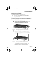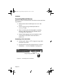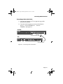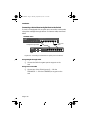
1
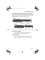
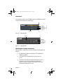
FRCH1Book Page 1 Thursday, September 25, 1997 11:23 AM
FriendlyNet
Fast Ethernet Switch
FS4004DS/FS4008DS
User’s Manual
FRCH1Book Page 2 Thursday, September 25, 1997 11:23 AM
FRCH1Book Page 1 Thursday, September 25, 1997 11:23 AM
FriendlyNet
Fast Ethernet Switch
FS4004DS/FS4008DS
User’s Manual
Asanté Technologies, Inc.
821 Fox Lane
San Jose, CA 95131
1.800.662.9686
www.asante.com
September 1997
Part Number: 06-00384-00 Rev. A
FRCH1Book Page 2 Thursday, September 25, 1997 11:23 AM
Copyright Notice
Copyright 1997 by Asanté Technologies, Inc.
All rights reserved. No part of this manual, or any associated artwork, software, product
design or design concept, may be copied, reproduced or stored, in whole or in part, in
any form or by any means mechanical, electronic, optical, photocopying, recording or
otherwise, including translation to another language or format, without the express
written consent of Asanté Technologies, Inc.
Trademarks
Asanté Technologies and FriendlyNet are trademarks of Asanté Technologies, Inc.
Ethernet is a registered trademark of the Xerox Corporation. All brand names and products are trademarks or registered trademarks of their respective holders.
FCC Information
This device complies with part 15 of the FCC Rules. Operation is subject to the following two conditions: (1) this device may not cause harmful interference and (2) this
device must accept any interference received, including interference that may cause
undesired operation.
Operation of this equipment in a residential area is likely to cause interference, in which
case, the user, at his or her own risk and expense, will be required to correct the interference.
Asanté Warranty
Asanté Technologies, Inc. warrants that this product will be free from defects in title,
materials and manufacturing workmanship. If the product is found to be defective,
then, as your sole remedy and as the manufacturer’s only obligation, Asanté Technologies, Inc. will repair or replace the product.
This warranty is exclusive and is limited to the FriendlyNet Fast Ethernet Switch. This
warranty shall not apply to products that have been subjected to abuse, misuse, abnormal electrical or environmental conditions, or any condition other than what can be
considered normal use.
Warranty Disclaimers
Asanté Technologies, Inc. makes no other warranties, express, implied or otherwise,
regarding the FriendlyNet Fast Ethernet Switch, and specifically disclaims any warranty
for merchantability or fitness for a particular purpose.
The exclusion of implied warranties is not permitted in some states and the exclusions
specified herein may not apply to you. This warranty provides you with specific legal
rights. There may be other rights that you have which vary from state to state.
Limitation of Liability
The liability of Asanté Technologies, Inc. arising from this warranty and sale shall be
limited to a refund of the purchase price. In no event shall Asanté Technologies, Inc. be
liable for costs of procurement of substitute products or services, or for any lost profits,
or for any consequential, incidental, direct or indirect damages, however caused and on
any theory of liability, arising from this warranty and sale. These limitations shall apply
notwithstanding any failure of essential purpose of any limited remedy.
FRCH1Book Page iii Thursday, September 25, 1997 11:23 AM
Table of Contents
About This Manual . . . . . . . . . . . . . . . . . . . . . . . . . . . . . . . . v
Chapter Contents . . . . . . . . . . . . . . . . . . . . . . . . . . . . . . . . . . . . . . . v
Document Conventions . . . . . . . . . . . . . . . . . . . . . . . . . . . . . . . . . .vi
Introduction . . . . . . . . . . . . . . . . . . . . . . . . . . . . . . . . . . . 1-1
FriendlyNet Fast Ethernet Switch. . . . . . . . . . . . . . . . . . . . . . . . . .1-1
Features . . . . . . . . . . . . . . . . . . . . . . . . . . . . . . . . . . . . . . . . . . . . .1-2
Performance Features . . . . . . . . . . . . . . . . . . . . . . . . . . . . . . .1-3
Fast Ethernet and Switching Technology. . . . . . . . . . . . . . . . . . . .1-3
Fast Ethernet Technology . . . . . . . . . . . . . . . . . . . . . . . . . . . .1-3
Switching Technology. . . . . . . . . . . . . . . . . . . . . . . . . . . . . . .1-4
Switch acts as a bridge between network segments . . . .1-4
Switch supports network expansion . . . . . . . . . . . . . . . .1-4
Installation . . . . . . . . . . . . . . . . . . . . . . . . . . . . . . . . . . . . . 2-1
Package Contents . . . . . . . . . . . . . . . . . . . . . . . . . . . . . . . . . . . . . .2-1
Components. . . . . . . . . . . . . . . . . . . . . . . . . . . . . . . . . . . . . . . . . .2-2
FS4004DS. . . . . . . . . . . . . . . . . . . . . . . . . . . . . . . . . . . . . . . . .2-2
FS4008DS. . . . . . . . . . . . . . . . . . . . . . . . . . . . . . . . . . . . . . . . .2-3
Cabling and Voltage Requirements . . . . . . . . . . . . . . . . . . . . . . . .2-4
Mounting Configurations . . . . . . . . . . . . . . . . . . . . . . . . . . . . . . . .2-5
Desktop Mounting. . . . . . . . . . . . . . . . . . . . . . . . . . . . . . . . . .2-5
Wall Mounting the FS4004DS . . . . . . . . . . . . . . . . . . . . . . . . .2-6
Rack Mounting the FS4008DS . . . . . . . . . . . . . . . . . . . . . . . . .2-7
Page iii
FRCH1Book Page iv Thursday, September 25, 1997 11:23 AM
Connecting Network Devices. . . . . . . . . . . . . . . . . . . . . . . . . . . . 2-8
Connecting a PC to the Switch . . . . . . . . . . . . . . . . . . . . . . . 2-8
Connecting a Hub to the Switch . . . . . . . . . . . . . . . . . . . . . . 2-9
Connecting a Hub without an Uplink Port to the Switch . . 2-10
Connecting the Switch to Another Switch or Network
Device . . . . . . . . . . . . . . . . . . . . . . . . . . . . . . . . . . . . . . . . . 2-11
Powering on the Switch . . . . . . . . . . . . . . . . . . . . . . . . . . . . . . . 2-12
FS4004DS . . . . . . . . . . . . . . . . . . . . . . . . . . . . . . . . . . . . . . . 2-12
FS4008DS . . . . . . . . . . . . . . . . . . . . . . . . . . . . . . . . . . . . . . . 2-12
LED Indicators . . . . . . . . . . . . . . . . . . . . . . . . . . . . . . . . . . 3-1
LED Indicators on the Switch . . . . . . . . . . . . . . . . . . . . . . . . . . . .
LED Indicators for Power Connections . . . . . . . . . . . . . . . . .
LED Indicators for Port Connections . . . . . . . . . . . . . . . . . . .
Link/Activity LED . . . . . . . . . . . . . . . . . . . . . . . . . . . . . .
100Mbps Operation LED. . . . . . . . . . . . . . . . . . . . . . . . .
FDX/Col LED . . . . . . . . . . . . . . . . . . . . . . . . . . . . . . . . . .
LED Indicators for Switch Connections. . . . . . . . . . . . . . . . .
PC to Switch Connection . . . . . . . . . . . . . . . . . . . . . . . .
Switch to Hub Connection . . . . . . . . . . . . . . . . . . . . . . .
Switch to Switch or other Network Devices
Connection . . . . . . . . . . . . . . . . . . . . . . . . . . . . . . . . . . .
3-1
3-2
3-3
3-3
3-3
3-4
3-5
3-5
3-5
3-6
Troubleshooting . . . . . . . . . . . . . . . . . . . . . . . . . . . . . . . . A-1
Specifications . . . . . . . . . . . . . . . . . . . . . . . . . . . . . . . . . . B-1
Technical Support . . . . . . . . . . . . . . . . . . . . . . . . . . . . . . . C-1
Page iv
FRCH1Book Page v Thursday, September 25, 1997 11:23 AM
About This Manual
This manual discusses two models of the FriendlyNet Fast Ethernet
Switch:
❏
FS4004DS — four-port 10/100Mps Fast Ethernet Switch
❏
FS4008DS — eight-port 10/100Mps Fast Ethernet Switch
These models are similar in every respect except for the number of
ports.Therefore, unless otherwise noted, all information provided in
this manual is applicable to both.
Chapter Contents
This manual is divided into the following chapters and appendices:
❏
Chapter 1,“Introduction,” describes the FriendlyNet
FS4004DS and FriendlyNet FS4008DS Fast Ethernet
Switch and their features.
❏
Chapter 2,“Installation,” explains how to install, mount,
and power on the FriendlyNet Fast Ethernet Switch.
❏
Chapter 3,“LED Indicators,” describes how to interpret
the FriendlyNet Fast Ethernet Switch’s LEDs.
❏
Appendix A,“Troubleshooting,” explains how to troubleshoot problems by monitoring the FriendlyNet Fast
Ethernet Switch’s LEDs.
Page v
FRCH1Book Page vi Thursday, September 25, 1997 11:23 AM
About This Manual
❏
Appendix B,“Specifications,” describes the FriendlyNet
Fast Ethernet Switch’s technical specifications.
❏
Appendix C,“Technical Support” explains how to contact Asanté Technical Support.
Document Conventions
This manual uses the terms “Switch” (first letter upper case) to refer to
the FriendlyNet FS4004DS or FS4008DS 10/100Mbps Fast Ethernet
Switch, and “switch” (first letter lower case) to refer to all other Ethernet switches.
This manual uses the following conventions to convey instructions
and information:
❏
Page vi
Commands and key words are in boldface font.
∆
Note:
Noteworthy information, which contains helpful suggestions or references to other
sections in the manual, is in this format.
▲
Important! Significant information that calls
attention to important features or instructions is in
this format.
FRCH1Book Page 1 Thursday, September 25, 1997 11:23 AM
1
Introduction
This chapter introduces the FriendlyNet Fast Ethernet Switch. It also
provides an overview of Fast Ethernet and switching technology.
FriendlyNet Fast Ethernet Switch
Thank you for purchasing the Asanté FriendlyNet FS4004DS or the
FriendlyNet FS4008DS 10/100Mbps Fast Ethernet Switch.
The FS4004DS and FS4008DS are unmanaged 10/100 Fast Ethernet
switches designed to address increasing network bandwidth needs
and accommodate future network expansion.
FS4004DS
FriendlyNet
4-port Dual Speed Ethernet Switch
1
2
3
4
Uplink
100Mbps
or
1
2
3
4
Link/Act
Power
FDX /Col
10/100Mbps Ports
Figure 1-1
FriendlyNet FS4004DS
FS4008DS
FriendlyNet
8-port Dual Speed Ethernet Switch
1
Power
2
3
4
5
6
7
8
100Mbps
Uplink
or
1
2
3
4
5
6
7
8
Link/Act
FDX
/ Col
Switched 10/100Mbps Ports
Figure 1-2
FriendlyNet FS4008DS
Each Switch is simple to install and features power, collision, full
duplex, 10/100Mbps, and link/activity LEDs for easy monitoring of the
Switch and its ports.
For network expansion, each Switch has an uplink port that makes it
easy to connect it to another Fast Ethernet switch.
Page 1-1
FRCH1Book Page 2 Thursday, September 25, 1997 11:23 AM
Introduction
Features
The FriendlyNet FS4004DS and the FS4008DS have the following features:
❏
Compact size — designed for small to large workgroups
in space-limited areas; installs on desktop, mounts on
wall, or installs in a standard equipment rack (depends
on model)
❏
Plug-and-play installation
❏
Connects from four to eight (depends on model)
10Base-T or 100Base-TX segments per switch
❏
Contains an uplink/ MDI-II (media dependent interface)
port for uplink to another switch
❏
Auto-negotiation on all ports to determine network
speed
❏
Full- or half-duplex operation on all ports
❏
Allows cascading from any port to any number of
switches
❏
Complies with the IEEE 802.3u Fast Ethernet standard
❏
Works with Category 5 UTP (unshielded twisted-pair)
cable
❏
Contains power, collision, full duplex, 10/100Mbps, and
link/activity LEDs to aid network diagnosis and simple
management
❏
Ideal for deployment with multiple high-speed servers
for dedicated bandwidth 10Mbps or 100Mbps workgroups
❏
Combines dynamic memory allocation with store-andforward switching
Page 1-2
FRCH1Book Page 3 Thursday, September 25, 1997 11:23 AM
Fast Ethernet and Switching Technology
Performance Features
The FriendlyNet FS4004DS and the FS4008DS have the following performance features:
❏
❏
❏
❏
❏
❏
Store-and-forward switching scheme ensures data integrity
N-Way auto-negotiation on all ports automatically
senses port speed (10/100 Mbps) and duplex mode
(full duplex or half duplex)
Data forwarding rate of 148,800pps (packets per second) per port at 100% of wire-speed
Data filtering rate of 148,800pps per port at 100% of
wire-speed
8K active MAC address entry table per device (selflearning)
8MB (FS4008DS) or 4MB (FS4004DS) packet buffer per
device (dynamically allocated for each port)
Fast Ethernet and Switching Technology
This section provides a brief overview of Fast Ethernet and Ethernet
switching technology.
Fast Ethernet Technology
Fast Ethernet, or 100Base-T, represents a non-disruptive, smooth evolution from the current 10Base-T technology.
The100Mbps Fast Ethernet technology:
❏
❏
❏
❏
Extends the 10Mbps Ethernet standard to transmit and
receive data at 100Mbps
Maintains the CSMA/CD Ethernet protocol
Allows for simple upgrades, since it is compatible with
all other 10Mbps Ethernet environments
Takes advantage of your company’s existing investment
in hardware, software and personnel training
Page 1-3
FRCH1Book Page 4 Thursday, September 25, 1997 11:23 AM
Introduction
Switching Technology
An Ethernet switch is a device that can direct network traffic among
several Ethernet and Fast Ethernet networks.
A switch increases network capacity and decreases network loading
by making it possible for a LAN to be divided into different segments.
Switch acts as a bridge between network segments
A switch acts as a high-speed selective bridge between individual segments.
Traffic that needs to go from one segment to another is automatically
forwarded by a switch, without interfering with any other segments.
This allows the total network capacity to be multiplied, while decreasing network loading.
To ensure network reliability, a switch monitors each of its ports for
signal quality and automatically disconnects stations transmitting
excessive noise, reconnecting them when the problem is resolved.
A switch automatically truncates data packets that exceed the maximum length for IEEE 802.3u, preventing a device from blocking the
network by transmitting continuous data streams or extra-long packets.
Switch supports network expansion
For Fast Ethernet networks, a switch is an effective way of eliminating
problems of chaining hubs beyond the “two-repeater limit.”
A switch can be used to split parts of the network into different collision domains, making it possible to expand your Fast Ethernet network beyond the 205 meter network diameter limit for 100BASE-TX
networks.
Switches supporting both traditional 10Mbps Ethernet and 100Mbps
Fast Ethernet are also ideal for bridging between existing 10Mbps networks and new 100Mbps networks.
Page 1-4
FRCH1Book Page 1 Thursday, September 25, 1997 11:23 AM
2
Installation
This chapter explains how to install the FriendlyNet Fast Ethernet
Switch. It contains the following sections:
❏
Package Contents
❏
FriendlyNet Fast Ethernet Switch components
❏
Cabling and voltage requirements
❏
Mounting configurations
❏
Connecting network devices
❏
Powering on the Switch
Package Contents
The FriendlyNet FS4004DS and the FS4008DS are shipped with the
following items:
❏
(1) FriendlyNet 4-port FS4004DS or 8-port FS4008DS
Fast Ethernet Switch
❏
(1) AC power cord
❏
(4) Self-adhesive rubber feet
❏
(1) Wall-mount kit (FS4004DS only) which includes two
screws and two screw anchors
❏
(1) Rack-mount kit (FS4008DS only) which includes
two rack-mounting brackets and mounting screws
❏
(1) User’s Manual (this book)
Page 2-1
FRCH1Book Page 2 Thursday, September 25, 1997 11:23 AM
Installation
Components
This section describes the front- and back-panel layouts of the
FS4004DS and FS4008DS.
FS4004DS
The front panel of the FS4004DS consists of four 10/100 Mbps ports,
one Uplink port, and LED indicators. See Figure 2-1.
Uplink Port
FS4004DS
FriendlyNet
4-port Dual Speed Ethernet Switch
1
2
100Mbps
3
4
Uplink
or
1
2
3
4
Link/Act
Power
FDX /Col
10/100Mbps Ports
LEDs
Figure 2-1
Four 10/100 Ports
FriendlyNet FS4004DS front panel
The back panel of the FS4004DS consists of an AC power connector.
See Figure 2-2.
AC Power Connector
Figure 2-2
∆
FriendlyNet FS4004DS back panel
Note: The FS4004DS does not have a power switch.
The FS4004DS is automatically powered on as soon as
the power cord is connected to the FS4004DS and to a
power outlet
Page 2-2
FRCH1Book Page 3 Thursday, September 25, 1997 11:23 AM
Components
FS4008DS
The front panel of the FS4008DS consists of eight 10/100 Mbps ports,
one Uplink port, and LED indicators. See Figure 2-3.
Uplink Port
FS4008DS
FriendlyNet
8-port Dual Speed Ethernet Switch
1
2
3
4
5
6
7
8
100Mbps
Power
Uplink
or
1
2
3
4
5
6
7
8
Link/Act
FDX
/ Col
Switched 10/100Mbps Ports
LEDs
Figure 2-3
Eight 10/100 Ports
FriendlyNet FS4008DS front panel
The back panel of the FS4008DS consists of a power switch, an AC
power connector, and a system fan.
AC Power Connector
System Fan
Figure 2-4
Power Switch
FriendlyNet FS4008DS back panel
Page 2-3
FRCH1Book Page 4 Thursday, September 25, 1997 11:23 AM
Installation
Cabling and Voltage Requirements
This section describes the cabling and voltage requirements of the
Switch.
Cabling Requirements
100Base-TX requires data-grade (Category 5) UTP (unshielded twistedpair) cable.
▲ Important! Some installations have Category 5
cabling but do not have wall outlets and/or wiring
closet punch-down blocks that meet Category 5 requirements.
100Base-TX requires that all wiring and accessories
meet EIA/TIA 568B specifications for proper operation.
When wiring a 100Base-TX network, make sure that the
entire cable plant meets specifications.
Voltage Requirements
▲ Important! Check the AC power line voltage used in
your area. The AC power adapter included with your
Switch must match the power supply voltage used in
your area.
❏
Page 2-4
AC input power: Equal to the AC power voltage
used in your area
FRCH1Book Page 5 Thursday, September 25, 1997 11:23 AM
Mounting Configurations
Mounting Configurations
This section describes how to mount the Switch on a desktop or a
wall. It also explains how to install the Switch in an equipment rack.
Desktop Mounting
To mount the Switch on a desktop or shelf:
1
Attach the four rubber feet (supplied) to the bottom of each corner on the Switch. See Figure 2-5
FS4008DS
lyNet
Friend
Uplink
1
2
3
4
5
6
7
2
4
3
100Mbps
Link/Act
FDX
2
1
5
6
7
8
8
Power
Figure 2-5
or
tch
rnet Swi
l Speed Ethe
8-port Dua
0Mbps Ports
10/10
Switched
/ Col
Desktop mounting
Place the Switch on a flat, stable, horizontal desktop or shelf.
Make sure you allow enough ventilation space
between the Switch and surrounding objects.
The Switch is ready for network connections.
Page 2-5
FRCH1Book Page 6 Thursday, September 25, 1997 11:23 AM
Installation
Wall Mounting the FS4004DS
The FS4004DS comes with a wall-mount kit.
▲ Important! The FS4008DS cannot be mounted on a
wall.
To mount the FS4004DS on a wall, consider the following when selecting a site for the FS4004DS:
❏
Select a site that is free of obstructions from other
equipment or devices
❏
Place the Switch high enough to easily observe LED
indicators and to allow for easy power and cable access
❏
Decide whether you want the Switch’s front panel to
face either up or down
To mount the FS4004DS on a wall:
1
Measure the screw holes on the bottom of the
FS4004DS.
2
Drill two holes into the wall equalling the same distance as measured in step 1.
▲ Important! Do not drill the holes too deep into
the wall.
3
Insert the plastic anchors (supplied) into the drilled
holes and gently tap them in with a hammer.
4
Insert and turn the screws (supplied) into the plastic anchors, leaving a small portion of the screws
sticking out.
5
Lift the FS4004DS and align the slots on the bottom
of the FS4004DS with the screw anchors.
6
Gently slide the FS4004DS onto the screws.
The FS4004DS wall mounting is complete. The
FS4004DS is ready for network connections.
Page 2-6
FRCH1Book Page 7 Thursday, September 25, 1997 11:23 AM
Mounting Configurations
Rack Mounting the FS4008DS
The FS4008DS comes with a rack-mounting kit.
▲ Important! The FS4004DS cannot be installed
in an equipment rack.
The FS4008DS can be mounted in a standard 19-inch equipment rack.
This rack can be placed in a wiring closet with other equipment.
To install the FS4008DS in an equipment rack:
1
Attach the two mounting brackets (supplied) on
each side of the FS4008DS. See Figure 2-6.
Power
1
2
3
4
5
FriendlyN
6
7
et
8-port Dual Speed
8
100Mbps
Uplink
Ethernet Switch
or
Link/Act
FDX
1
FS4008DS
2
3
4
5
6
7
/ Col
8
Switched 10/100Mb
ps Ports
Figure 2-6
2
Attaching mounting brackets to the FS4008DS
Mount the FS4008DS in the equipment rack by
screwing the mounting brackets to the equipment
rack. See Figure 2-7.
Power
1
2
3
4
5
FriendlyNe
6
7
8-port Dual Speed
8
100Mbps
Link/Act
FDX
Uplink
t
Ethernet Switch
or
1
2
FS4008DS
3
4
5
/ Col
6
7
8
Switched 10/100Mbp
s Ports
Figure 2-7
Mounting the FS4008DS in an equipment rack
The FS4008DS rack mounting is complete. The
FS4008DS is ready for network connections.
Page 2-7
FRCH1Book Page 8 Thursday, September 25, 1997 11:23 AM
Installation
Connecting Network Devices
Before you connect network devices to the Switch, review the following guidelines:
✔ Make sure the network cable length is less than 100
meters.
✔ Use a straight-through twisted pair cable or a
cross-over cable.
✔ When connecting two switches together (cascading
switches), make sure that the link between them is
not longer than 100 meters.
✔ Network cable segments can be connected to, or disconnected from, the Switch while the Switch’s
power is on.
Connecting a PC to the Switch
❏
Use a two-pair Category 5 UTP straight-through cable
with RJ-45 connectors.
❏
Connect the PC to any of the Switch’s ports (1 -4 for the
FS4004DS or 1 - 8 for the FS4008DS). See Figure 2-8.
FS4008DS
FriendlyNet
1
Power
2
3
4
5
6
7
8-port Dual Speed Ethernet Switch
8
100Mbps
Uplink
or
1
2
3
4
5
Link/Act
FDX
/ Col
Switched 10/100Mbps Ports
straight-through cable
Figure 2-8
Page 2-8
Connecting a PC to the Switch
6
7
8
FRCH1Book Page 9 Thursday, September 25, 1997 11:23 AM
Connecting Network Devices
Connecting a Hub to the Switch
❏
Use a two-pair Category 5 UTP straight-through cable
with RJ-45 connectors.
❏
Connect the hub’s uplink port to any of the Switch’s
ports (1 – 4 for the FS4004DS or 1 – 8 for the
FS4008DS). See Figure 2-9.
FS4008DS
FS4008DS
FriendlyNet
1
2
3
4
5
6
7
8-port Dual Speed Ethernet Switch
8
Uplink
100Mbps
Power
or
1
2
3
4
5
6
7
8
Link/Act
FDX
/ Col
Switched 10/100Mbps Ports
straight-through cable
Hub
FriendlyNet
FH100TX5
8-port Fast Ethernet Hub
Partition Partition
Pwr
1
2
3
4
5
6
7
8
Col
Link/Activity
1
2
3
4
5
6
7
8
Uplink
OR
hub’s uplink port
Figure 2-9
Connecting a hub to the Switch
Page 2-9
FRCH1Book Page 10 Thursday, September 25, 1997 11:23 AM
Installation
Connecting a Hub without an Uplink Port to the Switch
If a hub is not equipped with an uplink port, connection can be made
using either a straight-through cable or a cross-over cable, as outlined
below.
FS4008DS switch
FS4008DS
FriendlyNet
1
2
3
4
5
6
7
8-port Dual Speed Ethernet Switch
8
Uplink
100Mbps
Power
or
1
2
3
4
5
6
7
8
Link/Act
FDX
/ Col
Switched 10/100Mbps Ports
cross-over
cable
straight-through cable
FriendlyNet
FH100TX5
8-port Fast Ethernet Hub
Partition Partition
Pwr
1
2
3
4
5
6
7
8
Col
Link/Activity
1
2
3
4
5
6
7
8
Hub
Figure 2-10 Connecting a hub without an uplink port to the Switch
Using Straight-Through Cable
❏
Connect the Switch’s uplink port to any port on the
hub.
Using Cross-over Cable
❏
Connect any of the Switch’s ports (1 – 4 for the
FS4004DS or 1 – 8 for the FS4008DS) to any port on the
hub.
Page 2-10
FRCH1Book Page 11 Thursday, September 25, 1997 11:23 AM
Connecting Network Devices
Connecting the Switch to Another Switch or Network Device
The Switch can be connected to another switch or to other network
devices (such as a router, bridge, etc.) via a two-pair Category 5 UTP
straight-through or cross-over cable. See Figure 2-11.
Switch A
FS4008DS
FriendlyNet
1
2
3
4
5
6
8-port Dual Speed Ethernet Switch
8
7
Uplink
100Mbps
Power
or
1
2
3
4
5
6
7
8
Link/Act
FDX
/ Col
Switched 10/100Mbps Ports
cross-over cable
straight-through cable
Switch B
FS4008DS
FriendlyNet
1
2
Power
3
4
5
6
7
8-port Dual Speed Ethernet Switch
8
100Mbps
Uplink
or
1
2
3
4
5
6
7
8
Link/Act
FDX
/ Col
Switched 10/100Mbps Ports
Figure 2-11 Connecting the Switch to another switch or network device
Using Straight-Through Cable
❏
Connect the Switch’s uplink port to any of the other
switch’s/device’s 10Mbps or 100Mbps ports.
Using Crossover Cable
❏
Connect any port on the Switch (Switch A) to any of the
10Mbps or 100Mbps ports on the other switch (switch
B).
Page 2-11
FRCH1Book Page 12 Thursday, September 25, 1997 11:23 AM
Installation
Powering on the Switch
This section describes how to power on the FS4004DS and the
FS4008DS Fast Ethernet Switch.
FS4004DS
The FS4004DS’s may be turned on with or without LAN segment
cables connected.
To power on the FS4004DS:
1
Connect one end of the power cord (supplied) into
the AC power connector on the FS4004DS’ back
panel.
2
Connect the power cord to a local power source
outlet.
Note: There is no power switch on the FS4004DS.
The FS4004DS is automatically powered on as soon as
the power cord is connected to the Switch and to a
power outlet.
The FS4008DS’s power supply adjusts to the local
power source automatically. .
FS4008DS
The FS4009DS may be turned on with or without LAN segment cables
connected
To power on the FS4008DS:
1
Connect one end of the power cord (supplied) into
the AC power connector on the FS4008DS’ back
panel.
2
Connect the power cord to a local power source
outlet.
3
Turn the power switch to the “on” position.
The FS4008DS’s power supply adjusts to the local
power source automatically. .
Page 2-12
FRCH1Book Page 1 Thursday, September 25, 1997 11:23 AM
3
LED Indicators
This chapter explains how to interpret the front-panel LED indicators
on the FriendlyNet Fast Ethernet Switch.
The indicators are discussed in the following sections.
❏
LED indicators on the Switch
❏
LED indicators for power connections
❏
LED indicators for port connections
❏
LED indicators for Switch connections
LED Indicators on the Switch
The LED indicators on the Switch are used to facilitate monitoring and
troubleshooting.
These LEDs are:
❏
Power
❏
Link/Act (Link/Activity)
❏
100 Mbps Operation
❏
FDX/Col (Full-duplex/Collision)
Page 3-1
FRCH1Book Page 2 Thursday, September 25, 1997 11:23 AM
LED Indicators
The front-panel LEDs for the FS4004DS and the FS4008DS are shown
in Figure 3-1 and Figure 3-2, respectively.
FriendlyNet
4-port Dual Speed Ethernet Switch
1
2
3
Uplink
1
2
or
100Mbps
Link/Activity
Full Duplex/
10/100M
Collision
4
100Mbps
Link/Act
Power
FDX /Col
Power
Figure 3-1
FS4004DS LEDs
Power
1
Power
2
3
4
5
6
7
8
100Mbps
Link/Act
FDX
Figure 3-2
/ Col
100Mbps
Link/Activity
Full Duplex/
Collision
FS4008DS LEDs
LED Indicators for Power Connections
After the Switch is turned on, the LED indicators should respond as
follows:
❏
All LED indicators blink momentarily. This represents a
reset of the system.
❏
The FDX/Col LED indicators blink from yellow to
green.
❏
The power LED indicator lights and remains ON. If this
indicator is not lit, check to make sure that the AC
power connector is properly connected in the socket
and that the power switch is ON.
Page 3-2
FRCH1Book Page 3 Thursday, September 25, 1997 11:23 AM
LED Indicators for Port Connections
LED Indicators for Port Connections
Link/Activity LED
The green Link/Activity LED indicates if there is a device detected on
the other end of the port and if there is traffic on the port.
Table 3-1 describes the possible status indications of the Link/Activity
LEDs.
Table 3-1 Link/Activity LED status indicators
State
Status
On
Normal data/link pulse reception
Off
No twisted-pair cable connected
Link pulse disabled at other end
No power to the switch, twisted-pair connection
faulty
Non-100Base-TX device at other end
Twisted-pair cable exceeds recommended length
Blinking
Receiving network traffic
100Mbps Operation LED
The 100Mbps Operation LED indicates if a 10Mbps or a 100Mbps
device is connected to the port.
Table 3-2 describes the possible status indications of the 100Mbps
Operation LED
Table 3-2 100Mpbs LED status indicators
State
Status
On
A 100Mbps device is connected to a port or the
uplink port
Off
A 10Mbps device is connected to a port or the
uplink port
Page 3-3
FRCH1Book Page 4 Thursday, September 25, 1997 11:23 AM
LED Indicators
FDX/Col LED
The FDX/Col (full duplex/collision) LED indicates when a port is in full
duplex (FDX) mode, or when two or more stations on the specific network segment attempt to transmit packets simultaneously, causing a
packet collision.
∆
Note: This LED can display both green and yellow
colors (see Table 3-1).
∆
Note: Collisions are normal in Fast Ethernet networks.
Excessive collisions may indicate that your network is
congested.
Table 3-1 describes the possible status indications of the FDX/Col
LEDs.
Table 3-1 FDX/Collision LED status indicators
State
Status
On (green)
Port is in full duplex (FDX) mode
Off
Port is in half duplex (HDX) mode
Blinking (yellow)
Two or more stations on the network are
attempting to transmit packets simultaneously to
the port, causing a collision
Page 3-4
FRCH1Book Page 5 Thursday, September 25, 1997 11:23 AM
LED Indicators for Switch Connections
LED Indicators for Switch Connections
PC to Switch Connection
The LED indicators for PC connection are dependent on the PC’s LAN
card capabilities.
Table 3-2 describes the possible status indications of the PC to Switch
connections:
Table 3-2 PC to Switch Connection LED Status
100 Mbps
Link/Activity
FDX/Collision
On
Connected at
100 Mbps
PC connected
Connected at
full duplex
mode
Off
Connected at
10 Mbps
PC not connected
Connected at
half duplex
mode
Switch to Hub Connection
Table 3-3 describes the possible status indications of the Switch to
Hub connection:
Table 3-3 Hub to Switch Connection LED Status
Hub Types
100Mbps
Link/Act
FDX/
Collision
10BaseT Hub
OFF
ON
OFF
100Base-T Hub
ON
ON
OFF
Page 3-5
FRCH1Book Page 6 Thursday, September 25, 1997 11:23 AM
LED Indicators
Switch to Switch or other Network Devices Connection
Table 3-4 describes the possible status indications of the Switch to
switch or other network devices connection.
Table 3-4 Switch to Switch Connection LED Status
FDX/
Collision
Cable Types
100Mbps
Link/Act
Straight Cable
ON 100Mbps
ON
Depends on
the connected
switch or
other devices
ON
Depends on
the connected
switch or
other devices
OFF 10Mbps
Crossover Cable
ON 100Mbps
OFF 10Mbps
Page 3-6
FRCH1Book Page 1 Thursday, September 25, 1997 11:23 AM
A
Troubleshooting
Table A-1 describes how to troubleshoot problems with your network
and/or the Switch by monitoring the Switch’s LEDs.
Table A-1 Troubleshooting
Problem
Action
Power LED is off
✔
Make sure the power adapter is connected to
the power outlet and is properly inserted into
the power connector on the switch.
✔
Determine if the power outlet is functional by
plugging another device into the receptacle.
Collision LED is
blinking constantly
Collisions are normal in Fast Ethernet networks; however, excessive collisions may indicate that your network is overly congested.
✔
Make sure the workstation cables do not
exceed the maximum length of 100 meters.
✔
Make sure the workstation cables meet EIA/
TIA 568B specifications for Category 5 wiring.
✔
Make sure the total network diameter does not
exceed the maximum distance.
✔
Make sure there are no faulty Fast Ethernet
adapters or other equipment on the network.
Page A-1
FRCH1Book Page 2 Thursday, September 25, 1997 11:23 AM
Troubleshooting
Problem
Action
Link LED is off
✔
✔
Make sure the switch is powered on.
✔
Make sure the proper cabling is used between
the device and the Switch (refer to the cable
guidelines specified in Chapter 2).
✔
Make sure the correct cable is properly connected to the Switch and the network device.
✔
Make sure the cable does not exceed recommended length (100 meters).
✔
Make sure the duplex mode on both ends of
the link connection is configured to the same
mode (half or full duplex).
✔
If your adapter card supports NWay autonegotiation, make sure the driver also supports full duplex mode.
Slow performance
Page A-2
Make sure the device on the other end is powered on.
FRCH1Book Page 1 Thursday, September 25, 1997 11:23 AM
B
Specifications
FS4004DS and FS4008DS Specifications
Standards
❏
❏
❏
❏
IEEE 802.3 10Base-T Ethernet
IEEE 802.3u 100Base-TX Fast Ethernet
IEEE 802.3 frame types: transparent
IEEE 802.3 MAC layer frame size: 64 to
1518 bytes
Protocol
CSMA/CD
Data Transfer Rate
Ethernet: Fast Ethernet
10Mbps (half duplex): 100Mbps (half duplex)
20Mbps (full duplex): 200Mbps (full duplex)
Topology
Star
Network Cables
10Base-T:
❏
2-pair UTP Category 5 (100m maximum)
100Base-TX:
❏
Number of Ports
2-pair UTP Category 5 (100m maximum)
FS4004DS: 4 x 10/100 Mbps ports
FS4008DS: 8 x 10/100 Mbps ports
Page B-1
FRCH1Book Page 2 Thursday, September 25, 1997 11:23 AM
Specifications
FS4004DS and FS4008DS Specifications
Media Interface
Exchange
MDI-II RJ-45 shared with port 1x
Physical and Environmental
AC Inputs
100 - 240 VAC, 50/60 Hz (internal universal power
supply)
Power
Consumption
40 watts maximum
Operating
Temperature
32° – 122° F (0° - 50° C)
Storage
Temperature
-22° – 140° F (-30° – 60° C)
Humidity
5% to 95% non-condensing
Dimensions
FS4004DS: 232 x 142 x 43 mm (1U)
FS4008DS: 324 x 231 x 43 mm (1U)
Weight
FS4004DS: 1.2Kg
FS4008DS: 2.5Kg
EMI
FCC Class A, CE Mark, VCCI Class I
Safety
UL (UL 1950), CSA (CSA950)
Page B-2
FRCH1Book Page 3 Thursday, September 25, 1997 11:23 AM
Performance Specifications
FS4004DS and FS4008DS Specifications
Performance
Transmission
Method
Store-and-forward
RAM Buffer
FS4004DS: 4MB per device
FS4008DS: 8MB per device
Filtering Address
Table
8K entries per device
Packet Filtering/
Forwarding Rate
148,800 pps per port (for 100 Mbps)
Page B-3
FRCH1Book Page 4 Thursday, September 25, 1997 11:23 AM
FRCH1Book Page 1 Thursday, September 25, 1997 11:23 AM
C
Technical Support
Contacting Technical Support
To contact Asanté Technical Support:
Telephone
(800) 622-7464
Fax
(408) 432-6018
Fax-Back
(800) 741-8607
Internet Mail
[email protected]
World Wide Web Site
http://www.asante.com
Bulletin Board Service (BBS)
(408) 432-1416
ARA BBS (guest log-in)
(408) 894-0765
AppleLink Mail/BBS
ASANTE
FTP Archive
ftp.asante.com
Technical Support Hours
6:00 a.m. to 5:00 p.m. Pacific Standard Time USA, Monday - Friday.
Page C-1
FRCH1Book Page 2 Thursday, September 25, 1997 11:23 AM
FRCH1Book Page i Thursday, September 25, 1997 11:23 AM
Index
Numerics
E
100Base-TX, cables supported B-1
100Mbps LED 3-3
10Base-T, cables supported B-1
10Mbps LED 3-3
EMI B-2
equipment rack installation 2-7
expansion, network 1-4
A
fast ethernet
features of 1-3
overview 1-3
switch. See FS4008DS or FS4004DS
FDX/collision LED 3-4
features 1-2
performance 1-3
filtering
address table B-3
rate, data 1-3
/forwarding rate, packet B-3
forwarding rate, data 1-3
FriendlyNet switch. See FS4004DS or
FS4008DS
front panel LEDs, overview 3-1
FS4004DS
back panel 2-2
components 2-2
features 1-2
front panel 2-2
LEDs
diagram 3-2
overview 3-1
mounting options 2-5
overview 1-1
performance features 1-3
power, connecting 2-12
specifications B-1
wall mounting 2-6
FS4008DS
back panel 2-3
components 2-3
equipment rack installation 2-7
features 1-2
front panel 2-3
LEDs
diagram 3-2
overview 3-1
about this manual v
AC
inputs B-2
power connector 2-3
activity LED 3-3
address
entry table, MAC 1-3
table, filtering B-3
assistance. See technical support
auto-negotiation 1-3
B
bridge vs. switch 1-4
buffer
packet 1-3
RAM B-3
C
cabling requirements 2-4
category 5 cable 2-4
chapter contents v
collisions
LED 3-4
troubleshooting A-1
CSMA/CD B-1
D
data
filtering rate 1-3
forwarding rate 1-3
transfer rate B-1
desktop mounting 2-5
devices, connecting 2-8 – 2-11
dimensions B-2
document conventions vi
duplex mode, troubleshooting A-2
F
Index-i
FRCH1Book Page ii Thursday, September 25, 1997 11:23 AM
FS4008DS (continued)
mounting options 2-5
overview 1-1
performance features 1-3
power, connecting 2-12
specifications B-1
full duplex
LED 3-4
troubleshooting A-2
H
help. See technical support or
troubleshooting
hub
connecting to switch 2-9, 2-10
to switch, LED 3-5
humidity B-2
I
IEEE 802.3 B-1
installation 2-1
cabling requirements 2-4
devices, connecting
hub to switch 2-9, 2-10
PC to switch 2-8
switch to switch 2-11
network devices, connecting 2-8
package contents 2-1
powering on 2-12
voltage requirements 2-4
installation
desktop mounting 2-5
equipment rack installation 2-7
mounting options 2-5
wall mounting 2-6
L
LEDs
collision
description 3-4
troubleshooting A-1
duplex
description 3-4
troubleshooting A-2
Index-ii
LEDs (continued)
link/activity
description 3-3
troubleshooting A-2
overview 3-1
PC to switch connection 3-5
power
troubleshooting A-1
connections 3-2
switch
to hub connection 3-5
to switch connection 3-6
link
LED 3-3
troubleshooting A-2
M
MAC address entry table 1-3
manual
about v
chapter contents v
document conventions vi
media interface exchange B-2
mounting options 2-5
desktop 2-5
equipment rack 2-7
wall 2-6
N
network
cables supported B-1
devices
connecting 2-8
guidelines 2-8
expansion 1-4
segments, defined 1-4
O
operating temperature B-2
overview v, vi
fast ethernet 1-3
installation 2-1
manual v
switch 1-1
switching technology 1-3
FRCH1Book Page iii Thursday, September 25, 1997 11:23 AM
P
package contents 2-1
packet
buffer 1-3
filtering/forwarding rate B-3
PC (personal computer)
connecting to switch 2-8
to switch, LED 3-5
performance
features 1-3
troubleshooting A-2
personal computer (PC), connecting
to switch 2-8
port
100Mbps LED 3-3
10Mbps LED 3-3
activity LEDs 3-3
connection LEDs 3-4
link LEDs 3-3
power
connecting 2-12
connector 2-3
consumption B-2
LEDs 3-2
troubleshooting A-1
problems, determining A-1
product overview 1-1
protocol, supported B-1
R
rack, equipment, installation 2-7
RAM buffer B-3
requirements
cabling 2-4
voltage 2-4
switch
connecting to another switch 2-11
defined 1-4
to switch, LED 3-6
vs. bridge 1-4
See also FS4008DS or FS4004DS
switching
overview 1-3
scheme 1-3
technology, overview 1-4
system fan 2-3
T
table
filtering address B-3
MAC address entry 1-3
technical
specifications B-1
support C-1
temperature
operating B-2
storage B-2
topology supported B-1
transmission method B-3
troubleshooting A-1
U
UTP (unshielded twisted-pair)
cable 2-4
V
voltage requirements 2-4
W
wall mounting 2-6
weight B-2
S
safety specifications B-2
segments, network, defined 1-4
specifications B-1
standards, supported B-1
storage temperature B-2
store-and-forward switching
scheme 1-3
support, technical C-1
Index-iii
FRCH1Book Page iv Thursday, September 25, 1997 11:23 AM
FRCH1Book Page 1 Thursday, September 25, 1997 11:23 AM
FRCH1Book Page 2 Thursday, September 25, 1997 11:23 AM
ASANTÉ TECHNOLOGIES, INC., 821 FOX LANE, SAN JOSE, CA 95131
PHONE: 408.435.8388, 800.662.9686 • FAX: 408.432.7511 • e-mail address: [email protected] •
World Wide Web site: http://www.asante.com
©1997 Asanté Technologies Inc., Asanté is a trademark of Asanté Technologies, Inc.
All brand names and products are trademarks or registered trademarks of their respective holders.
September 1997
Part Number 06-00384-00 Rev. A