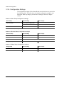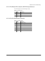
1
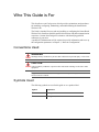
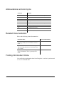
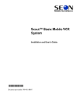
Smart-Reach™ Wireless Link
Installation and Configuration Guide
Manual Type
700 0055
700-0055 R001
Seon Design® Inc.
Seon Design Inc. is a specialist in the design and manufacture of video surveillance systems for mobile applications. Seon has
been the preferred solutions provider for the pupil transportation industry since 1999. Today, we are proud that our success in
this area has made us the leading manufacturer of mobile video surveillance systems in North America.
Contact Information
Seon Design Inc.
Unit 111, 3B Burbidge Street
Coquitlam, BC
Canada V3K 7B2
Telephone
Toll Free Telephone
Fax
Toll Free Fax
Email
Web site
604.941.0880
1.877.630.7366
604.941.0870
1.866.664.3677
[email protected]
www.seon.com
Seon Design Inc. Trademarks
Seon Design Inc. holds the following trademarks:
Explorer™ is a registered trademark of Seon Design Inc.
“Seon Design” is a registered trademark of Seon Design Inc.
The Seon logo (
) is a registered trademark of Seon Design Inc.
In this User Manual there are references to trademarks, registered trademarks, and product names not owned by Seon Design
Inc. that are the property of their respective owners. They are used in this User Manual for identification purposes only.
User Manual Revision
This is the November 2007 revision for this User Manual and is copyright, November 2007 of Seon Design Inc. All rights
reserved.
Exclusion of Liability
SEON DESIGN INC.:
(a) MAKES NO REPRESENTATION, WARRANTY, GUARANTEE OR COVENANT, EXPRESS OR IMPLIED, AS TO THE ACCURACY,
SUFFICIENCY OR SUITABILITY OF ANY TECHNICAL OR OTHER INFORMATION PROVIDED IN THIS USER MANUAL OR ANY OTHER
USER OR OTHER MANUAL OR OTHER DOCUMENTATION PROVIDED BY SEON DESIGN INC. WITH RESPECT TO THE PRODUCT(S)
DESCRIBED HEREIN, INCLUDING WITHOUT LIMITATION ANY DESCRIPTION OF GOODS OR SERVICES, SPECIFICATIONS, MODELS,
DRAWINGS, OR DIAGRAMS.
(b) DOES NOT ASSUME AND SHALL NOT BE SUBJECT TO AND DISCLAIMS ANY AND ALL RESPONSIBILITY AND/OR LIABILITY FOR
LOSSES, DAMAGES, COSTS OR EXPENSES ARISING OUT OF BREACH OF CONTRACT OR OF WARRANTY, TORT (INCLUDING
NEGLIGENCE AND STRICT LIABILITY) OR OTHERWISE, WHETHER SPECIAL, DIRECT, INDIRECT, CONSEQUENTIAL, INCIDENTAL,
SPECIAL OR CONTINGENT, WHICH MIGHT ARISE OUT OF THE USE OF SUCH INFORMATION. THE USE OF ANY SUCH INFORMATION
WILL BE ENTIRELY AT THE USER ’S RISK; AND
(c) EXPRESSLY DISCLOSES THAT IF THIS MANUAL IS WRITTEN IN ANY LANGUAGE OTHER THAN ENGLISH, THAT ALTHOUGH
SEON DESIGN INC. HAS USED REASONABLE CARE TO MAINTAIN THE ACCURACY OF THE TRANSLATION FROM THE ENGLISH
LANGUAGE, THE ACCURACY OF SUCH TRANSLATION IS NOT GUARANTEED OR WARRANTED BY SEON DESIGN INC. PLEASE REFER
TO THE ENGLISH LANGUAGE VERSION OF THIS USER MANUAL FOR APPROVED SEON CONTENT. THE ENGLISH LANGUAGE
VERSION IS AVAILABLE UPON REQUEST FROM THE SEON CUSTOMER SERVICE DEPARTMENT.
Please refer to the Seon Design Inc. Product Warranty applicable to the Product(s) described in this User Manual which
exclusively sets forth Seon Design Inc.’s entire liability arising from or in connection with such product(s) and their use and
the exclusive remedies available for purchasers and users thereof.
Document Part Number
This User Manual is valid for Seon Design Inc. Document Part Number 700-0055.
PRINTED IN CANADA
Who This Guide is For
This Installation and Configuration Guide provides explanations and procedures
for installing, configuring, maintaining, and troubleshooting the Smart-Reach
Wireless Link.
The Guide is intended for users who are installing or configuring the Smart-Reach
Wireless Link. Installers should be qualified electricians with data communication
experience. Contact Seon Design for assistance with identifying qualified
contractors in your area.
A qualified IT administrator will be required to provide information and/or set up
the configuration parameters in Chapter 3, “Network Configuration”.
Conventions Used
WARNING
Warnings identify conditions or practices that could result in personal injury or loss of life.
CAUTION
Cautions identify conditions or practices that could result in damage to the unit or other
equipment.
Important: These notes describe things which are important for you to know, but are
not as serious as a Caution.
Symbols Used
The following symbols are used in this guide or on a product label.
700-0055 R001
Symbol
Explanation
&
Warning or Caution
Earth (ground) terminal
iii
Abbreviations and Acronyms
Acronym
Definition
IEEE
Institute of Electrical and Electronics Engineers
LAN
Local Area Network
MAC
Address
Media Access Control address
SSID
Security Set Identifier
SMA-RP
SubMiniature version A, Reverse Polarity
WI-FI
Wireless Fidelity
WEP
Wired Equivalent Privacy
WLAN
Wireless Local Area Network
WPA
Wi-Fi Protected Access
Related Documentation
Refer to the following related documentation.
Document Name
Document Part Number
Explorer™ EX8 Plus Mobile Digital Video
Recording (DVR) System, Installation and User’s
Guide
700-0048
Explorer™ EX4 Basic and Plus Mobile Digital
Video Recording (DVR) System, Installation and
User’s Guide
700-0042
Explorer™ Mobile Digital Video Recording
System: DVR Remote Viewer, Quick Reference
Guide
700-0056
Finding Information Online
You can find more information about Seon Design Inc. as well as its products and
services at www.seon.com.
iv
700-0055 R001
Contents
Chapter 1
Introduction
1.1. About the Smart-Reach Wireless Network- - - - - - - - - - - - - - - - - - - - - - - - - - - - - - - - - - - 1–2
1.2. Smart-Reach Product Features - - - - - - - - - - - - - - - - - - - - - - - - - - - - - - - - - - - - - - - - - - - 1–3
Chapter 2
Installation
2.1. Installing the Smart-Reach Wireless LAN - - - - - - - - - - - - - - - - - - - - - - - - - - - - - - - - - - - 2–2
2.2. Installation Materials - - - - - - - - - - - - - - - - - - - - - - - - - - - - - - - - - - - - - - - - - - - - - - - - - 2–3
2.2.1. Smart-Reach Vehicle Installation Kit - - - - - - - - - - - - - - - - - - - - - - - - - - - - - - - - - - 2–3
2.2.2. WLAN Mobile Antenna Kit - - - - - - - - - - - - - - - - - - - - - - - - - - - - - - - - - - - - - - - - 2–3
2.2.3. Smart-Reach Base Station Installation Kit - - - - - - - - - - - - - - - - - - - - - - - - - - - - - - - 2–3
2.2.4. WLAN Terminal Antenna Kit - - - - - - - - - - - - - - - - - - - - - - - - - - - - - - - - - - - - - - - 2–4
2.3. Installing the Smart-Reach Vehicle Station and Antenna - - - - - - - - - - - - - - - - - - - - - - - - - 2–4
2.3.1. Step 1: Choosing a Location for the WLAN Mobile Antenna - - - - - - - - - - - - - - - - - - 2–4
2.3.2. Step 2: Installing the Mounting Assembly for the Antenna - - - - - - - - - - - - - - - - - - - - 2–5
2.3.3. Step 3: Mounting the WLAN Mobile Antenna - - - - - - - - - - - - - - - - - - - - - - - - - - - - 2–6
2.3.4. Step 4: Mounting the Smart-Reach - - - - - - - - - - - - - - - - - - - - - - - - - - - - - - - - - - - - 2–6
2.3.5. Step 5: Connecting to the Smart-Reach Front Panel - - - - - - - - - - - - - - - - - - - - - - - - 2–7
2.3.6. Step 6: Connecting to the Smart-Reach Back Panel - - - - - - - - - - - - - - - - - - - - - - - - - 2–9
2.4. Installing the Smart-Reach Base Station and Antenna - - - - - - - - - - - - - - - - - - - - - - - - - - 2–10
2.4.1. Step 1: Choosing a Location for the Base Station Antenna - - - - - - - - - - - - - - - - - - - 2–10
2.4.2. Step 2: Mounting the Smart-Reach - - - - - - - - - - - - - - - - - - - - - - - - - - - - - - - - - - - 2–12
2.4.3. Step 3: Connecting to the Smart-Reach Front Panel - - - - - - - - - - - - - - - - - - - - - - - 2–12
Chapter 3
Network Configuration
3.1. Setting up the Smart-Reach Wireless Network - - - - - - - - - - - - - - - - - - - - - - - - - - - - - - - - 3–2
3.1.1. Network Topologies - - - - - - - - - - - - - - - - - - - - - - - - - - - - - - - - - - - - - - - - - - - - - - 3–2
3.1.2. System Requirements - - - - - - - - - - - - - - - - - - - - - - - - - - - - - - - - - - - - - - - - - - - - - 3–2
3.1.3. Configuring the TCP/IP Settings on the Computer - - - - - - - - - - - - - - - - - - - - - - - - - 3–2
3.1.4. Setting up the Network Settings on the DVR - - - - - - - - - - - - - - - - - - - - - - - - - - - - - 3–5
3.1.5. Configuring the Smart-Reach - - - - - - - - - - - - - - - - - - - - - - - - - - - - - - - - - - - - - - - 3–5
3.2. Configuring the Terminal Program - - - - - - - - - - - - - - - - - - - - - - - - - - - - - - - - - - - - - - - - 3–6
3.3. Using the Smart-Reach Network Software- - - - - - - - - - - - - - - - - - - - - - - - - - - - - - - - - - - 3–8
3.3.1. Using the Basic Setup Menu - - - - - - - - - - - - - - - - - - - - - - - - - - - - - - - - - - - - - - - 3–10
3.3.2. Using the Wireless Setup Menu - - - - - - - - - - - - - - - - - - - - - - - - - - - - - - - - - - - - - 3–11
3.3.3. Using the Bridge Setup - - - - - - - - - - - - - - - - - - - - - - - - - - - - - - - - - - - - - - - - - - - 3–14
3.3.4. Configuration Settings - - - - - - - - - - - - - - - - - - - - - - - - - - - - - - - - - - - - - - - - - - - 3–16
700-0055 R001
v
Contents
Chapter 4
Maintenance and Troubleshooting
4.1. Updating the Software Program - - - - - - - - - - - - - - - - - - - - - - - - - - - - - - - - - - - - - - - - 4.2. Hardware and Connection Setup - - - - - - - - - - - - - - - - - - - - - - - - - - - - - - - - - - - - - - - - 4.2.1. DB-9 to RS-232 Asynchronous - - - - - - - - - - - - - - - - - - - - - - - - - - - - - - - - - - - - - 4.2.2. 4-Pin Molex AUX connector (RS-232) Asynchronous - - - - - - - - - - - - - - - - - - - - - 4.2.3. 8-Pin RJ-45 Ethernet Connector - - - - - - - - - - - - - - - - - - - - - - - - - - - - - - - - - - - - -
Appendix A
4–2
4–2
4–2
4–3
4–3
Specifications
A.1. Smart-Reach Wireless Link - - - - - - - - - - - - - - - - - - - - - - - - - - - - - - - - - - - - - - - - - - - - A–2
A.2. Antenna - - - - - - - - - - - - - - - - - - - - - - - - - - - - - - - - - - - - - - - - - - - - - - - - - - - - - - - - - A–3
A.2.1. WLAN Mobile Antenna Specifications - - - - - - - - - - - - - - - - - - - - - - - - - - - - - - - - A–3
A.2.2. WLAN Terminal Antenna Specifications - - - - - - - - - - - - - - - - - - - - - - - - - - - - - - - A–3
A.2.3. N-Male to N-Female Bulkhead 90 V Lightning Protector - - - - - - - - - - - - - - - - - - - - A–4
SEON DESIGN® INC. PRODUCT WARRANTY
DISCLAIMER - - - - - - - - - - - - - - - - - - - - - - - - - - - - - - - - - - - - - - - - - - - - - - - - - - - - - - W–2
Provisions Applicable to American Customers - - - - - - - - - - - - - - - - - - - - - - - - - - - - - - - - - W–3
Provisions Applicable to Canadian Customers - - - - - - - - - - - - - - - - - - - - - - - - - - - - - - - - - W–3
vi
700-0055 R001
Tables
Table 2-1
Table 2-2
Table 2-3
Table 3-1
Table 3-2
Table 3-3
Table 3-4
Table 3-5
Table 3-6
Table 3-7
Table 4-1
Table 4-2
Table 4-3
WLAN mobile antenna location requirements - - - - - - - - - - - - - - - - - - - - - - - - - - - - - 2–4
Smart-Reach front panel features - - - - - - - - - - - - - - - - - - - - - - - - - - - - - - - - - - - - - - 2–7
Smart-Reach back panel features - - - - - - - - - - - - - - - - - - - - - - - - - - - - - - - - - - - - - - 2–9
Terminal emulator program settings - - - - - - - - - - - - - - - - - - - - - - - - - - - - - - - - - - - - 3–6
Basic Setup menu items - - - - - - - - - - - - - - - - - - - - - - - - - - - - - - - - - - - - - - - - - - - 3–11
Wireless Setup menu - - - - - - - - - - - - - - - - - - - - - - - - - - - - - - - - - - - - - - - - - - - - - 3–13
Bridge Setup menu - - - - - - - - - - - - - - - - - - - - - - - - - - - - - - - - - - - - - - - - - - - - - - 3–15
Basic Setup Configuration settings- - - - - - - - - - - - - - - - - - - - - - - - - - - - - - - - - - - - 3–16
Wireless Setup Configuration settings - - - - - - - - - - - - - - - - - - - - - - - - - - - - - - - - - 3–16
Bridge Setup Configuration settings - - - - - - - - - - - - - - - - - - - - - - - - - - - - - - - - - - - 3–16
DB-9 Pinouts - - - - - - - - - - - - - - - - - - - - - - - - - - - - - - - - - - - - - - - - - - - - - - - - - - - 4–2
AUX Pinouts - - - - - - - - - - - - - - - - - - - - - - - - - - - - - - - - - - - - - - - - - - - - - - - - - - - 4–3
RJ-45 Pinouts - - - - - - - - - - - - - - - - - - - - - - - - - - - - - - - - - - - - - - - - - - - - - - - - - - - 4–3
700-0055 R001
vii
viii
Figures
Figure 1-1
Figure 2-1
Figure 2-2
Figure 2-3
Figure 2-4
Figure 2-5
Figure 2-6
Figure 2-7
Figure 2-8
Figure 2-9
Figure 2-10
Figure 2-11
Figure 3-1
Figure 3-2
Figure 3-3
Figure 3-4
Figure 3-5
Figure 3-6
Figure 3-7
Figure 3-8
Figure 3-9
Figure 3-10
Figure 3-11
Figure 3-12
Figure 3-13
Figure 3-14
Figure 3-15
Figure 3-16
Figure 3-17
Figure 3-18
Figure 3-19
Figure 3-20
Figure 3-21
Smart-Reach wireless network - - - - - - - - - - - - - - - - - - - - - - - - - - - - - - - - - - - - - - - 1–2
Smart-Reach wireless network: Vehicle and base stations - - - - - - - - - - - - - - - - - - - - - 2–2
Mounting assembly - - - - - - - - - - - - - - - - - - - - - - - - - - - - - - - - - - - - - - - - - - - - - - - 2–5
Stacking order on the mounting assembly - - - - - - - - - - - - - - - - - - - - - - - - - - - - - - - - 2–6
Smart-Reach mounting points - - - - - - - - - - - - - - - - - - - - - - - - - - - - - - - - - - - - - - - - 2–7
Smart-Reach front panel- - - - - - - - - - - - - - - - - - - - - - - - - - - - - - - - - - - - - - - - - - - - 2–7
Control connector 2-pin Molex - - - - - - - - - - - - - - - - - - - - - - - - - - - - - - - - - - - - - - - 2–8
Smart-Reach back panel - - - - - - - - - - - - - - - - - - - - - - - - - - - - - - - - - - - - - - - - - - - - 2–9
Installing the base station antenna on the bracket - - - - - - - - - - - - - - - - - - - - - - - - - - 2–10
Attaching lighting protector and antenna cable- - - - - - - - - - - - - - - - - - - - - - - - - - - - 2–11
SMA RP coaxial cable - - - - - - - - - - - - - - - - - - - - - - - - - - - - - - - - - - - - - - - - - - - - 2–11
Smart-Reach power adapter - - - - - - - - - - - - - - - - - - - - - - - - - - - - - - - - - - - - - - - - 2–12
Network and Internet Connections window - - - - - - - - - - - - - - - - - - - - - - - - - - - - - - - 3–2
Network Connections window - - - - - - - - - - - - - - - - - - - - - - - - - - - - - - - - - - - - - - - 3–3
Network Connections window - - - - - - - - - - - - - - - - - - - - - - - - - - - - - - - - - - - - - - - 3–3
Local Area Connection Properties window - - - - - - - - - - - - - - - - - - - - - - - - - - - - - - - 3–4
Internet Protocol (TCP/IP) Properties - - - - - - - - - - - - - - - - - - - - - - - - - - - - - - - - - - - 3–4
Tera Term: New connection window - - - - - - - - - - - - - - - - - - - - - - - - - - - - - - - - - - - 3–6
Tera Term: Terminal setup window - - - - - - - - - - - - - - - - - - - - - - - - - - - - - - - - - - - - 3–7
Tera Term: Serial port setup window - - - - - - - - - - - - - - - - - - - - - - - - - - - - - - - - - - - 3–7
Welcome to Smart Reach window - - - - - - - - - - - - - - - - - - - - - - - - - - - - - - - - - - - - - 3–8
Smart-Reach main menu - - - - - - - - - - - - - - - - - - - - - - - - - - - - - - - - - - - - - - - - - - - 3–9
Basic Setup menu–Operation Mode - - - - - - - - - - - - - - - - - - - - - - - - - - - - - - - - - - - 3–10
Basic Setup menu–Hostname - - - - - - - - - - - - - - - - - - - - - - - - - - - - - - - - - - - - - - - 3–10
Basic Setup menu–Software Versions - - - - - - - - - - - - - - - - - - - - - - - - - - - - - - - - - 3–10
Wireless Setup menu - - - - - - - - - - - - - - - - - - - - - - - - - - - - - - - - - - - - - - - - - - - - - 3–11
Wireless Setup menu–ESSID - - - - - - - - - - - - - - - - - - - - - - - - - - - - - - - - - - - - - - - 3–12
Wireless Setup menu–Channel - - - - - - - - - - - - - - - - - - - - - - - - - - - - - - - - - - - - - - 3–12
Wireless Setup menu– Encryption Mode- - - - - - - - - - - - - - - - - - - - - - - - - - - - - - - - 3–12
Wireless Setup menu–Encryption Key - - - - - - - - - - - - - - - - - - - - - - - - - - - - - - - - - 3–13
Bridge Setup menu - - - - - - - - - - - - - - - - - - - - - - - - - - - - - - - - - - - - - - - - - - - - - - 3–14
Bridge Setup menu–IP Address - - - - - - - - - - - - - - - - - - - - - - - - - - - - - - - - - - - - - - 3–14
Bridge Setup menu–Network - - - - - - - - - - - - - - - - - - - - - - - - - - - - - - - - - - - - - - - 3–15
700-0055 R001
ix
x
CHAPTER 1
Introduction
This chapter describes the product features and components of the SmartReach™ wireless network.
The Smart-Reach wireless network is for use with the Explorer series of
Mobile Digital Video Recording (DVR) Systems from Seon Design, which
includes the EX4 and EX8 family of products.
Introduction
1.1. About the Smart-Reach Wireless Network
What is a SmartReach wireless
network?
The Smart-Reach wireless LAN (local area network) is a communication system
designed for mobile applications.
In a standard Smart-Reach wireless network, as shown in Figure 1-1, a SmartReach vehicle station and a small mobile antenna are installed onboard a vehicle
with an Explorer DVR. Another Smart-Reach unit is located in the office with a
terminal antenna to create the base station. The base station is the connection
point that ties wireless communication devices into a network.
Using this system, the surveillance footage on the DVRs can be accessed by a
qualified user from the base station while the vehicle is in the yard.
The Smart-Reach wireless network is based on the IEEE 802.11b and 802.11g
wireless standards to provide a secure, high-speed connection. Password
protection and wireless encryption help to ensure that all communication can only
be accessed by authorized personnel.
Customizing the
Smart-Reach
network
The Smart-Reach network has the robustness to service a fleet of one vehicle or
several vehicles. A variety of antennas are available depending on your
application and site requirements.
Figure 1-1 Smart-Reach wireless network
1–2
700-0055 R001
Introduction
1.2. Smart-Reach Product Features
The Smart-Reach wireless network has been designed using extremely reliable
and easy-to-use technology, including:
•
•
•
•
•
•
•
•
700-0055 R001
Wireless DVR access that provides a high-speed connection to Explorer
DVRs.
Proven technology using the IEEE 802.11b and 802.11g wireless LAN
standard (2.4 GHz frequency).
Remote DVR access of live and recorded video footage using DVR Remote
Viewer, a Web-based program using the Internet Explorer® Web browser.
Two wireless operating modes as a vehicle station or base station.
Compact enclosure allows the Smart-Reach to be installed close to the
antenna, improving signal quality and range.
Different antennas are available to accommodate different vehicles.
Robust design engineered for operating reliability in harsh environments:
• Operating temperature range of –40°F to 158°F (–40°C to 70°C).
• Power input range of 10 to 32 VDC.
Field upgradeable software uses a standard USB memory device for SmartReach.
1–3
1–4
CHAPTER 2
Installation
This chapter provides information and procedures for installing the SmartReach wireless local area network (WLAN). The steps include installing:
• the Smart-Reach and WLAN mobile antenna onboard a vehicle.
• the Smart-Reach and WLAN terminal antenna at the base station.
Installation
2.1. Installing the Smart-Reach Wireless LAN
When planning the installation of the Smart-Reach wireless network, select a dry
indoor location for the Smart-Reach unit where the unit is not exposed to
moisture. Install the Smart-Reach within proximity of the antenna, which is
designed to be mounted in an outdoor location.
In a standard network, as shown in Figure 2-1, the Smart-Reach vehicle station is
installed onboard the vehicle within three feet of the mobile antenna for optimum
signal performance. The Smart-Reach base station is installed in the yard office
with a terminal antenna.
Important: Installers should be qualified electricians with data communications
experience. If you need assistance with identifying qualified contractors in your area,
please contact Seon Design for more information.
Before beginning the installation, assemble all the necessary system components
and inspect the units for any scratches or damage. Use the appropriate tools for the
installation.
Vehicle station with mobile antenna
Base station with terminal antenna
Figure 2-1 Smart-Reach wireless network: Vehicle and base stations
2–2
700-0055 R001
Installation
2.2. Installation Materials
The following materials are required to complete the installation of the SmartReach wireless LAN.
2.2.1. Smart-Reach Vehicle Installation Kit
The Smart-Reach vehicle installation kit includes the following materials:
•
•
•
•
•
•
•
•
•
•
Smart-Reach vehicle station
Power harness (20 ft)
Control harness (20 ft)
Ethernet cable, CAT5e (20 ft)
Fuse 1 A
Fuse holder (in-line)
Butt splice connector, 14–16 AWG on both ends
Four #10 × ¾ sheet metal screws
Four #10 × ¾ self drilling screws
Four #10 external lock washers
2.2.2. WLAN Mobile Antenna Kit
For specifications, see “WLAN Mobile Antenna Specifications” on page A–3.
The installation kit includes the following materials:
•
•
•
Antenna, 2 dBi, 1.5" × 3.5", white
Mounting hardware
Coaxial cable SMA-RP NMOHF, RG-58 (3.28 ft)
2.2.3. Smart-Reach Base Station Installation Kit
Two Ethernet CAT5e cables are required for installing the Smart-Reach base
station and are available by contacting your sales representative at Seon Design or
from any computer store. Purchase the length required for your installation.
The following materials are included in the installation kit:
•
•
•
•
•
•
•
•
700-0055 R001
Smart-Reach base station
Smart-Reach 110 V power adapter
Coaxial cable SMA-RP plug, RG-58 (6.5 ft)
Lightning protector, N-Male to N-Female (For specifications, see page A–4.)
Ethernet CAT5e cross-over adapter, RJ-45F to RJ-45F
Four #10 × ¾ sheet metal screws
Four #10 × ¾ self drilling screws
Four #10 external lock washers
2–3
Installation
2.2.4. WLAN Terminal Antenna Kit
For specifications, see “WLAN Terminal Antenna Specifications” on page A–3.
The following materials are included in the installation kit:
•
•
Antenna, 6 dBi radome omni, 12.25"
L mount bracket
2.3. Installing the Smart-Reach Vehicle Station and
Antenna
The Smart-Reach vehicle station is clearly labelled and is meant to be installed on
the vehicle. The vehicle station is configured before the product is shipped to the
customer. To change the configuration, see Chapter 3, “Network Configuration”.
The WLAN mobile antenna is installed on the roof of the vehicle. The antenna is
provided with a coaxial cable to connect to the Smart-Reach. For optimum signal
reception, use the antenna cable provided with the Smart-Reach. Longer cables
can be obtained; however, a longer antenna cable results in a weaker signal
strength, which means a shorter wireless range, similar to voltage losses which
occur on long transmission lines.
2.3.1. Step 1: Choosing a Location for the WLAN Mobile Antenna
The location of the antenna will affect the performance of the wireless network.
Install the antenna in a outdoor location that meets the requirements described in
Table 2-1:
Table 2-1 WLAN mobile antenna location requirements
Location requirement
Description
Close to the Smart-Reach
vehicle station on the vehicle.
The transmitting antenna must be within 3 feet
(1 meter) of the Smart-Reach unit on the vehicle.
Requires 3 feet (1 meter) of
clearance from other antennas.
The WLAN mobile antenna must have 3 feet
(1 meter) of clearance from any other antenna on the
vehicle, such as a GPS antenna or a radio antenna
used for onboard communication.
Requires a clear line-of-sight
view.
The onboard antenna requires a clear line-of-sight
view to the receiving antenna in the base station. The
antenna cannot be obstructed.
Important: Microwave ovens and cordless phones, for example, and other wireless
networks use the same 2.4 GHz frequency band as Smart-Reach. When too many devices
are being used simultaneously, signal interference can occur and affect performance.
2–4
700-0055 R001
Installation
2.3.2. Step 2: Installing the Mounting Assembly for the Antenna
The following procedure summarizes the mounting assembly installation. For
complete identification of parts and an illustrated procedure, see the product
documentation that is included with the Radiall/Larsen WLAN mobile LPT 2400
NMOHFW antenna.
To install the mounting assembly:
1. Drill a ¾" hole on a flat and metallic surface of the vehicle.
A fiberglass surface is less than optimal for installing the mounting assembly.
If the vehicle skin is not metal, Seon Design will provide a ground plane,
which is tin-plated copper. Contact Seon Design for more information.
2. Metal-to-metal contact between the vehicle and the mount will provide the
best performance. Remove any burrs on the under side of the hole.
3. Screw the locking nut onto the mounting assembly, and twist the nut
one-and-a-half turns. Feed the coax cable and the serrated part of the
mounting assembly through the hole, going from the bottom to topside of the
hole.
4. Pull up on the locking nut, and place the mounting step into proper alignment
in the hole. Continue pulling the locking nut upwards and tighten the nut until
it is finger tight. Check that the O ring between the locking nut and mounting
assembly is seated properly.
5. Holding the mounting assembly with a spanner wrench or long nose pliers,
use an adjustable or open end wrench on the locking nut and tighten firmly
(60 in-lbs. or 6.8 Nm maximum). Do not overtighten.
Mounting assembly
Mounting step
Figure 2-2 Mounting assembly
700-0055 R001
2–5
Installation
2.3.3. Step 3: Mounting the WLAN Mobile Antenna
To mount the WLAN mobile antenna:
1. Place the required gasket on the base of the antenna.
2. Align the antenna threads with the threads of the base and turn slowly.
3. Stop turning when the antenna feels snug on the base. Do not overtighten.
Figure 2-3 Stacking order on the mounting assembly
2.3.4. Step 4: Mounting the Smart-Reach
The typical mounting location for the Smart-Reach vehicle station will be inside a
vehicle’s electrical panel or header panel, within three feet of the antenna.
CAUTION: Equipment damage
Smart-Reach is rated for indoor use only and must be mounted in a dry location. Do not
expose the Smart-Reach to moisture.
The Smart-Reach unit can be installed in any orientation as long as the front and
back panel connections are accessible. Four mounting points are located on the
flanges for securing the unit.
2–6
700-0055 R001
Installation
Mounting points
Figure 2-4 Smart-Reach mounting points
To install the Smart-Reach:
1. Use the four #10 × ¾ sheet metal screws or the #10 × ¾ self drilling screws
and #10 external lock washers to secure the Smart-Reach to the surface.
2.3.5. Step 5: Connecting to the Smart-Reach Front Panel
The Smart-Reach front panel provides the following connections and indicator
light, as shown in Figure 2-5.
Figure 2-5 Smart-Reach front panel
Table 2-2 Smart-Reach front panel features
Item
Feature
Description
1
ETHERNET
The ETHERNET RJ-45 connector is used to connect to the DVR.
2
POWER
The POWER indicator (green) illuminates when the Smart-Reach
is powered on.
3
CTRL
The 2-pin control connector is for connecting the Smart-Reachto-DVR control harness.
4
12/24 VDC
The 3-pin POWER IN connector is for connecting the Smart-Reach
to the electrical panel of the vehicle.
POWER IN
700-0055 R001
2–7
Installation
To connect the CAT5e cable to the front panel:
1. Connect one end of the 20 ft CAT5e cable to the Ethernet RJ-45 connector.
2. Connect the other end of the cable to the ETHERNET connector on the DVR.
To customize your installation, longer Ethernet cables are available by contacting
your sales representative at Seon Design.
To connect the power harness to the vehicle’s electrical panel:
Power is supplied from the vehicle and not from the DVR. The power harness
uses the supplied 1 A fuse with the in-line automative fuse holder to protect the
red positive (+) battery wire.
1. Connect the black negative (–) battery power wire to the vehicle’s electrical
panel.
2. Strip the red wire end appropriately. Use the supplied butt splice connector to
connect the fuse holder to the red battery power wire. Connect the other end
of the fuse holder directly to the vehicle’s electrical panel.
3. The in-line fuse holder consists of a black plastic piece with an attached cap
that simply pulls apart. Install the 1 A fuse and push the holder back together.
4. Connect the POWER IN harness to the 12/24 VDC POWER IN connector.
To customize your installation, longer power harness cables are available by
contacting your sales representative at Seon Design.
To connect the 2-pin control connector:
1. Connect the 2-pin connector to the CTRL connector on the Smart-Reach.
2. Connect the 2-pin connector to the CONTROL connector on the DVR or on the
Smart-Link module.
Figure 2-6 Control connector 2-pin Molex
2–8
700-0055 R001
Installation
Powering the
Smart-Reach
Smart-Reach powers on when the Record Delay-On Time of the DVR1 is over,
and the DVR powers up the cameras and Smart-Reach.
When the Power Delay-Off Time2 is over, the DVR and Smart-Reach power
down.
To customize your installation, longer control signal cables are available by
contacting your sales representative at Seon Design.
2.3.6. Step 6: Connecting to the Smart-Reach Back Panel
Figure 2-7 Smart-Reach back panel
Table 2-3 Smart-Reach back panel features
Item
Feature
Description
1
ANTENNA SMA-RP
The ANTENNA SMA-RP provides the connection for a coaxial
cable from the antenna to the Smart-Reach.
2
AUX
The AUX connector is for Seon Design use only.
3
USB
The USB port supports USB devices for upgrading the
Smart-Reach software.
4
DIAGNOSTIC
The DB-9 serial port is for diagnostic purposes only.
1. Connect the coaxial cable from the antenna to the ANTENNA SMA-RP
connection on the back panel of the Smart-Reach.
2. Hand tighten the ANTENNA SMA-RP connection. The specified torque spec is
3–5 in-lbs (0.34–0.57 Nm). Do not overtighten.
1. Record Delay-On Time determines when the DVR system will start up. Record Delay-on Time is a configurable setting with values ranging from 0 seconds to 60 minutes. For more information on this feature, see the Installation and User’s Guide of the
DVR.
2. Power Delay-Off Time keeps power and control signal to the DVR only after the
vehicle ignition is turned off to allow a remote connection to access the DVR’s video.
Power Delay-Off Time is a configurable setting with values ranging from 0 minutes to
255 minutes. For more information on this feature, see the Installation and User’s
Guide of the DVR.
700-0055 R001
2–9
Installation
2.4. Installing the Smart-Reach Base Station and Antenna
The Smart-Reach base station is clearly labelled and is meant to be installed in the
yard office. The base station is configured before the product is shipped to the
customer. To change the configuration, see Chapter 3, “Network Configuration”.
2.4.1. Step 1: Choosing a Location for the Base Station Antenna
The base station antenna is supplied with an L mount bracket and a lightning
protector. (For more information on the base station antenna and lightning
protector, see Appendix A, “Specifications”.)
WARNING: Shock hazard
Check with the local electrical code requirements for the proper installation and grounding
of the lightning protector. Seon Design Inc. is not responsible for improper installation of
the lightning protector and does not provide protection against lightning strikes.
To install the base station antenna:
1. Secure the L mount bracket to the desired location on the outside of the
building.
2. Insert the antenna into the bracket and secure with the washer and nut, as
shown in Figure 2-8.
Figure 2-8 Installing the base station antenna on the bracket
3. Attach the lightning protector, as shown in Figure 2-2.
2–10
700-0055 R001
Installation
Base station antenna
Lightning protector
Ground terminal Coaxial cable
Figure 2-9 Attaching lighting protector and antenna cable
4. Use 12 AWG stranded wire (recommended) to connect the ground terminal
on the lightning protector to a pipe in the ground.
5. Connect the SMA-RP connector on the coaxial cable, as shown in Figure 2-10,
to the ANTENNA SMA-RP connector on the Smart-Reach.
6. Connect the other end of the cable to the lightning protector, as shown in
Figure 2-9. Tighten to a torque spec of 6–10 in-lbs (0.68–1.13 Nm). Do not
overtighten.
Figure 2-10 SMA RP coaxial cable
700-0055 R001
2–11
Installation
2.4.2. Step 2: Mounting the Smart-Reach
Mount the Smart-Reach in a dry location as described in “Step 4: Mounting the
Smart-Reach” on page 2–6.
2.4.3. Step 3: Connecting to the Smart-Reach Front Panel
1. Connect the Ethernet cable on the Smart-Reach to a computer using two
CAT5e cables and the supplied cross-over adapter.
The cross-over adapter uses normal CAT5 cable in the installation.
2. Connect the AC power adapter to the 12/24 VDC POWER IN connector.
Figure 2-11 Smart-Reach power adapter
3. Connect the AC power adapter to a 110 VAC source.
This configuration does not require a control cable.
2–12
700-0055 R001
CHAPTER 3
Network Configuration
This chapter provides information and procedures for planning and
configuring the Smart-Reach wireless local area network (WLAN). The
steps include:
• setting up the computer
• setting up the DVR
• configuring the Smart-Reach unit as a vehicle station (bridge) or a
base station (access point)
Network Configuration
3.1. Setting up the Smart-Reach Wireless Network
A qualified IT administrator will be required to provide network information.
3.1.1. Network Topologies
The wireless network configuration involves multiple vehicles. Each vehicle will
have a WLAN mobile antenna and a Smart-Reach vehicle station installed
onboard. Another Smart-Reach unit will be installed in the yard office and serves
as the base station.
3.1.2. System Requirements
A computer with the following minimum requirements is required:
•
•
a serial port
a terminal program such as HyperTerminal for Windows 2000/XP or Tera
Term for Windows
3.1.3. Configuring the TCP/IP Settings on the Computer
In order to set up the network, configure the TCP/IP settings on the computer and
set up the network menu on the DVR. A qualified IT administrator will be
required to provide information about the network.
To set up the TCP/IP settings on a computer running Windows 2000/XP:
1. Click on Start. In Control Panel, click Network and Internet Connections.
Figure 3-1 Network and Internet Connections window
3–2
700-0055 R001
Network Configuration
Figure 3-2 appears.
2. Click Network Connections.
Figure 3-2 Network Connections window
Figure 3-3 appears.
3. Click on Local Area Connection.
Figure 3-3 Network Connections window
700-0055 R001
3–3
Network Configuration
4. Under Network Tasks, click Change settings of this connection or right-click
to display Properties.
Figure 3-4 appears.
Figure 3-4 Local Area Connection Properties window
5. Under the General tab, click on Internet Protocol (TCP/IP), and click
Properties.
Figure 3-5 Internet Protocol (TCP/IP) Properties
3–4
700-0055 R001
Network Configuration
6. Click Use the following IP address.
7. In IP address, enter the IP address (typical 192.168.1.2).
8. In Subnet mask, enter the Subnet mask for the network (typical 255.255.0.0.).
9. In Default gateway, enter the IP address of the router or gateway on the LAN.
10. Click Use the following DNS server addresses, and enter the IP address of
the DNS server on the network.
11. Click OK.
3.1.4. Setting up the Network Settings on the DVR
The Explorer DVRs have a built-in network interface for connecting to an office
network or to certain peripheral devices.
Use the Network menu in the main menu to set the communication parameters,
such as an IP address, Subnet mask, and gateway IP.
To configure the network settings on the DVR, see using the Network menu in the
Installation and User’s Guide of your DVR.
3.1.5. Configuring the Smart-Reach
The Smart-Reach unit is configured at the factory to serve as a vehicle station or
as a base station. If the settings need to be reconfigured, see “Using the SmartReach Network Software” on page 3–8.
700-0055 R001
3–5
Network Configuration
3.2. Configuring the Terminal Program
A terminal program like HyperTerminal or Tera Term (a free open source terminal
program) communicates with the Smart-Reach unit through the serial port. Use
the appropriate terminal program for your Windows operating system.
To set up HyperTerminal:
1. Click on Start> All> Programs> Accessories> Communications>
HyperTerminal.
The New Connection window appears.
2. Type a name for the connection.
3. Click OK.
4. In the Com Port properties window, enter the standard settings for the
terminal emulator program described in Table 3-1.
Table 3-1 Terminal emulator program settings
Item
Program settings
Terminal type
VT100
Baud rate
115200
Data bits
8 bit
Parity
None
Stop bits
1 bit
Flow control
None
To set up Tera Term:
1. If you choose to use the Tera Term program, you can download it from
http://www.neocom.ca. Follow the on-screen instructions for installing onto
the computer.
2. Double click on the Tera Term icon to open the program.
3. In the File menu, click New Connection.
Figure 3-6 appears.
Figure 3-6 Tera Term: New connection window
3–6
700-0055 R001
Network Configuration
4. Select Serial, set the Port to COM1 (or to the COM port that will be used).
5. Click OK.
6. In the Setup menu, select Terminal.
Figure 3-7 appears.
Figure 3-7 Tera Term: Terminal setup window
7. Set the Terminal ID to VT100. Click OK.
8. In the Setup menu, select Serial Port.
Figure 3-8 appears.
Figure 3-8 Tera Term: Serial port setup window
9. Enter the standard settings for the serial port, as shown in Figure 3-8.
10. Click OK.
700-0055 R001
3–7
Network Configuration
3.3. Using the Smart-Reach Network Software
Use the Smart-Reach software to configure the unit for the different operating
modes as a vehicle station or as a base station.
The network menu appears as shown in Figure 3-9.
Figure 3-9 Welcome to Smart Reach window
To log on to Seon Smart-Reach:
1. Enter the login username: admin (default).
2. Press Enter.
3. Enter the password: admin (default).
4. Press Enter.
The Smart-Reach main menu appears as shown in Figure 3-10.
3–8
700-0055 R001
Network Configuration
Figure 3-10 Smart-Reach main menu
The menu has three sub menus:
•
•
•
Basic Setup
Wireless Setup
Bridge Setup
5. Use the left and right arrow keys on your keyboard to move between the three
menu items. Use the up arrow and down arrow keys to move between the submenu items.
The flashing cursor and asterisk indicate which menu item is active.
6. Press Enter to select the highlighted item.
Important: Pressing the Escape key on the keyboard will close and restart the SmartReach software program. Press Enter to select menu items. The exception is the Software
Versions menu—exit by pressing the Escape key.
700-0055 R001
3–9
Network Configuration
3.3.1. Using the Basic Setup Menu
Under the Basic Setup menu, select from the menu items which are described in
Table 3-2:
•
Operation Mode for Vehicle or Base.
Figure 3-11 Basic Setup menu–Operation Mode
•
Hostname
Figure 3-12 Basic Setup menu–Hostname
•
Software Versions wimenu V 0.91
Figure 3-13 Basic Setup menu–Software Versions
3–10
700-0055 R001
Network Configuration
Table 3-2 Basic Setup menu items
Item
Description
Operation Mode
VEHICLE
BASE
(Mobile Deployment) Configured as a wireless station.
(Base Station) Configured as a wireless access point.
Hostname
Enter a name to identify the device. For example, Vehicle (default
name is Mobile) or Base (default name).
Software
Versions
Identifies the software version. To exit the Software Versions
window, press the Escape key.
3.3.2. Using the Wireless Setup Menu
Set the configuration parameters for the wireless bridge in the Wireless Setup
menu. Under the Wireless Setup menu, select from the menu items which are
described in Table 3-3.
Figure 3-14 Wireless Setup menu
700-0055 R001
3–11
Network Configuration
The configuration parameters include:
•
ESSID
Figure 3-15 Wireless Setup menu–ESSID
•
Channel
Figure 3-16 Wireless Setup menu–Channel
•
Encryption Mode
Figure 3-17 Wireless Setup menu– Encryption Mode
3–12
700-0055 R001
Network Configuration
•
Encryption Key
Figure 3-18 Wireless Setup menu–Encryption Key
Table 3-3 Wireless Setup menu
700-0055 R001
Wireless Setup
Description
ESSID
ESSID
Channel
Channel selection ranges from 1 to 11. Select the channel which
will be the operating radio channel. Channel 11 is the default.
Encryption Mode
Encryption Mode uses WEP (Wired Encryption Privacy).
(WPA encryption will be available in the future.)
Encryption Key
Enter a 10-digit security encryption key.
(Extended Service Set Identifier) is the ID or name of a
wireless LAN which includes an access point. The ESSID must be
identical for all units on the wireless network.
3–13
Network Configuration
3.3.3. Using the Bridge Setup
Set the configuration parameters for the bridge connection in the Bridge Setup
menu. Under the Bridge Setup menu, select from the menu items which are
described in Table 3-4.
Figure 3-19 Bridge Setup menu
•
IP Address
Figure 3-20 Bridge Setup menu–IP Address
3–14
700-0055 R001
Network Configuration
•
Netmask
Figure 3-21 Bridge Setup menu–Network
Table 3-4 Bridge Setup menu
700-0055 R001
Ethernet Setup
Description
IP Address
The DHCP server is not available. Enter a static IP address for
the Smart-Reach unit.
Netmask
Enter the network mask 255.255.0.0.
3–15
Network Configuration
3.3.4. Configuration Settings
The configurations settings for the Smart-Reach network software are provided in
the following tables. The tables show the original configuration setting for each
menu item. Enter any changes you make to the settings in the Your Changes
column.
Table 3-5 Basic Setup Configuration settings
Basic Setup
Original Setting
Operation Mode
VEHICLE
BASE
Hostname
Your Changes
Mobile Deployment
Base Station
Vehicle
Software Versions (not changeable)
Table 3-6 Wireless Setup Configuration settings
Wireless Setup
Original Setting
ESSID
SEON
Channel
11
Encryption Mode
WEP
Encryption Key
1234567890
Your Changes
Wired Equivalent Privacy (not changeable)
Table 3-7 Bridge Setup Configuration settings
Bridge Setup
Original Setting
Your Changes
IP Address
Netmask
3–16
255.255.0.0.
700-0055 R001
CHAPTER 4
Maintenance and Troubleshooting
This chapter describes how to maintain and troubleshoot the Smart-Reach
wireless link.
Maintenance and Troubleshooting
4.1. Updating the Software Program
The software update must be obtained from Seon Design. Attempting to load
other software will not work on the Smart-Reach wireless link.
To install a software update, a USB memory device must be formatted from a
Windows computer using the FAT file format. Load the updated program onto the
USB memory device.
To install a software program update to the Smart-Reach:
1. Insert a USB memory device with the new software version into the USB
port.
2. Power up the Smart-Reach using the vehicle ignition.
The update procedure takes approximately 15 minutes.
Important: Do not turn the vehicle ignition off during the software update.
4.2. Hardware and Connection Setup
This section provides pinout information for the Diagnostic DB-9 serial port,
AUX connector, and RJ-45 Ethernet connector.
4.2.1. DB-9 to RS-232 Asynchronous
Communication control cable with DB-9 Female to DB-9 Female asynchronous
serial null modem cable. The cable length should be 10 feet.
Table 4-1 DB-9 Pinouts
4–2
Pin
Name
Description
1
N/C
No Connection
2
RX
Receive Data
3
TX
Transmit Data
4
N/C
No Connection
5
GND
Ground
6
N/C
No Connection
7
N/C
No Connection
8
N/C
No Connection
9
N/C
No Connection
700-0055 R001
Maintenance and Troubleshooting
4.2.2. 4-Pin Molex AUX connector (RS-232) Asynchronous
The AUX connector is for Seon Design use only.
Table 4-2 AUX Pinouts
Pin
Name
Description
1
N/C
No Connection
2
TX
Transmit Data
3
RX
Receive Data
4
GND
Ground
4.2.3. 8-Pin RJ-45 Ethernet Connector
Table 4-3 RJ-45 Pinouts
Pin
Name
1
Transmit Positive
2
Transmit Negative
3
Receive Positive
4
N/C
No Connection
5
N/C
No Connection
6
700-0055 R001
Description
Receive Negative
7
N/C
No Connection
8
N/C
No connection
4–3
4–4
Appendix A
Specifications
This appendix provides the product specifications for the Smart-Reach
wireless link and the antennas.
Note: Specifications are subject to change without notice.
Specifications
A.1. Smart-Reach Wireless Link
Wireless Specifications
IEEE Standard
IEEE Std. 802.11b (2.4 GHz)
IEEE Std. 802.11g (2.4 GHz)
Output power
600 mW
Encryption
WEP (Wired Equivalent Privacy)
WPA (Wi-Fi Protected Access) Currently not available
Wireless Operational Modes
Base Station
Non-mobile connection point
Vehicle Station
Used on mobile platform, allows access from any wireless
device (such as a laptop with a wireless card)
Interface Specifications
Power Input
3-pin: Ground, +Vbat, Control (+ input to activate)
Control Input
2-pin connector: Ground, control
Ethernet
RJ-45 connector, 10/100 Base T auto negotiation interface
Serial Console Port
DB-9 (male) for software update and diagnostics
USB
Host port for software updates
Antenna Connection
Reverse polarity SMA connector for 2.4 GHz
Environmental and Mechanical
Operating Temperature
–40°F to 158°F (–40°C to 70°C)
Storage Temperature
–40°F to 185°F (–40°C to 85°C)
Operating Humidity
0 to 95% relative humidity, non-condensing
Dimensions (H × W × D)
1.4 × 4.1 × 7.9" (35 × 103 × 200 mm)
Weight
0.88 lb (400 g)
Power Requirements
A–2
Power Input
10–32 VDC
Power Consumption
5 W (approximate)
Input Protection
Reverse polarity protection with in-line diode
Fuse
Requires external 1 A fuse (fast blow)
700-0055 R001
Specifications
A.2. Antenna
A.2.1. WLAN Mobile Antenna Specifications
WLAN Mobile Antenna
(LPT Low profile/Transit antenna)
Larsen® 2.4–2.5 GHz
Gain
20 dBi
Type
Low profile
VSWR (voltage standing wave ratio)
< 2.0:1
Power rating
10 W
Color
White
Base size
1.5"
Maximum height
3.5"
Coaxial cable
SMA RP NMOHF, RG-58, 3.28 ft
A.2.2. WLAN Terminal Antenna Specifications
WLAN Terminal antenna
Larsen® 2.4–2.5 MHz
Gain
6 dBi
Type
Radome omni
VSWR (voltage standing wave ratio)
1.5 maximum
Impedance
50 Ohm
Radiation pattern
Vertical plane: 30° typical
Horizontal plane: Omni-directional
Cross polarization
Vertical plane: > 23 dB
Horizontal plane: > 23 dB
700-0055 R001
Maximum input power
20 W
Operating temperature
–40° to 131°F (–40° to 55°C)
Ingress protection
IP67
Radome enclosure
Acrylonitrile Styrene Acrylate
Maximum length
12.25"
A–3
Specifications
A.2.3. N-Male to N-Female Bulkhead 90 V Lightning Protector
Lightning protector
Altelicon™, Multi-strike capability, Bi-directional
protection
Electrical Specifications
Frequency range
0–3 GHz
Protector complies with
IEC/IEEE Standard
VSWR (voltage standing wave ratio)
1:1.3 maximum (0–3 GHz)
Insertion loss
0.4 dB maximum (0–3 GHz)
Impedance
50 Ohm
Standard gas tube element
90 V ±20%
Gas tube insulation resistance
10,000 MΩ
Maximum withstand current
5 kA
Mechanical Specifications
A–4
Connector types
N-Male to N-Female bulkhead
Connector body material
Nickel plated brass
Body material
Aluminum
Pin material
Gold plated brass
O-ring material
Rubber
Ground lug
10 AWG maximum
12 AWG stranded copper wire recommended
Dimensions (H × W × D)
1.6 × 0.8 × 3.3" (40 × 20 × 84 mm)
Weight
3.17 oz (89.8 g)
700-0055 R001
SEON DESIGN® INC. PRODUCT WARRANTY
Seon Design Inc. (Seon) warrants the cameras and components listed below against defects in workmanship
and materials provided that such defects appear or are discovered within the respective periods specified
below and provided further that the purchaser of such products notifies Seon of such defects within thirty (30)
days of the appearance or discovery of such defects:
•
•
•
•
Five (5) years from date of purchase parts and labor on the SA Wedge Camera Series
One (1) year from date of purchase parts and labor on the SA-IR Illuminator
One (1) year from date of purchase parts and labor on the Explorer™ Mobile DVR Systems
One (1) year from date of purchase parts and labor on all other products and accessories
All service/replacement parts and repairs are warranted for a period of 90 days.
Subject to the terms and conditions listed below, during the relevant warranty period, Seon will repair,
replace, or refund the purchase price for the defective product, whichever Seon considers to be appropriate in
the circumstances, in Seon’s sole and arbitrary opinion, free of charge, any defective products returned
prepaid. In the event purchaser has a problem with any Seon product, please call and request a RETURN
AUTHORIZATION (RA) NUMBER from the Service Department.
Please call 877-630-7366 or (604) 941-0880 and ask for the Service Department. Be sure to have the model
number, serial number and the nature of the problem available for the customer service representative. Prior
authorization MUST be obtained for all returns, exchanges, or credits. ITEMS SHIPPED TO SEON WITHOUT A
CLEARLY IDENTIFIED RA NUMBER MAY BE REFUSED.
Products returned will be tested to verify the defect. Upon verification of the defect, the product will be
repaired or exchanged, or the purchase price will be refunded or credited to the customer’s account, at the sole
option of Seon. In the event of replacement, the returned product will be credited to the customer’s account
and a new invoice issued for the replacement item. Seon reserves the right to refund the purchase price or to
issue a credit only in lieu of replacement.
Seon may use new or refurbished replacement parts for repairing its products, at its sole and arbitrary
discretion. Seon may replace an entire unit with an equivalent model, at its sole and arbitrary discretion. If a
unit is exchanged, the returned product shall become the property of Seon and the exchange product becomes
the property of the purchaser, and the remainder of the warranty that applied to the original unit purchased
shall apply to the exchanged product. Exchange units may be new units or units that have been repaired to full
factory specifications at Seon’s discretion.
If the product is found to be in good working order or its inability to function properly is not covered by this
warranty, the product will be returned in the same condition as received unless repair is possible and
requested by the customer. Repairs of such nature will incur a charge for parts and labor and will proceed only
by agreement with the customer to accept the charge.
This warranty shall not apply:
(a) to equipment not supplied by Seon;
(b) to equipment, including, any components, which shall have been operated in excess of rated capacity,
subject to negligence, accident, or damage by circumstances beyond Seon’s control, or to improper
installation, operation, maintenance, servicing, alterations or storage, modification without Seon’s
written authorization, misuse, vandalism, fire, floods or acts of nature so as, in Seon’s exclusive and
arbitrary judgment, to affect the same adversely; or
(c) if the serial number for the product has been altered in any way.
700-0055 R001
W-1
(d) if the product has been operated outside of the specified Operating Environment specified in the
Seon Users Manual for such product.
DISCLAIMER
THIS WARRANTY IS EXCLUSIVE AND IN LIEU OF ALL OTHER REPRESENTATIONS, WARRANTIES,
GUARANTEES AND CONDITIONS, EXPRESS OR IMPLIED, STATUTORY OR OTHERWISE AND WITHOUT
LIMITING THE GENERALITY OF THE FOREGOING, SEON EXPRESSLY DISCLAIMS AND EXCLUDES ANY
IMPLIED WARRANTY OF MERCHANTABILITY, DURABILITY OR FITNESS FOR PURPOSE AND ANY
WARRANTIES OR MODIFIED WARRANTIES ARISING FROM USAGE OF TRADE OR COURSE OF DEALING.
Any description of the goods or services, whether in writing or made orally by Seon or Seon’s agents,
specifications, samples, models, bulletins, drawings, diagrams, engineering sheets or similar materials
used in connection with customer’s order are for the sole purpose of identifying the goods and/or services
and shall not be construed as an express warranty. Any suggestions by Seon or Seon’s agents regarding
use, applications or suitability of the goods and/or services shall not be construed as an express warranty
unless confirmed to be such in writing by Seon. Purchaser assumes full responsibility for selecting
products to achieve purchaser’s intended purposes, for properly installing and using those products, and for
verifying the results obtained therefrom.
PURCHASER’S EXCLUSIVE REMEDY AND SEON’S ENTIRE LIABILITY ARISING FROM OR IN CONNECTION
WITH PURCHASER’S USE OF THE PRODUCTS AND/OR THIS AGREEMENT SHALL BE REPAIR OR
REPLACEMENT OF DEFECTIVE PRODUCTS, OR REFUND OR CREDIT OF THE PURCHASE PRICE OF THE
PRODUCTS AS SET FORTH ABOVE. SEON SHALL NOT BE SUBJECT TO AND DISCLAIMS: (A) ANY OTHER
OBLIGATIONS OR LIABILITIES ARISING OUT OF BREACH OF CONTRACT OR OF WARRANTY, (B) ANY
OBLIGATIONS WHATSOEVER ARISING FROM TORT CLAIMS (INCLUDING NEGLIGENCE, AND STRICT
LIABILITY) OR ARISING UNDER OTHER THEORIES OF LAW WITH RESPECT TO GOODS SOLD OR
SERVICES RENDERED BY SEON, OR ANY UNDERTAKINGS, ACTS OR OMISSIONS RELATING THERETO, AND
(C) ALL CONSEQUENTIAL, INCIDENTAL, SPECIAL AND CONTINGENT DAMAGES WHATSOEVER, EVEN IF
SEON HAS BEEN SPECIFICALLY ADVISED OF THE POSSIBILITY OF SUCH DAMAGES.
Without limiting the generality of the foregoing, Seon specifically disclaims any liability for property or
personal injury damages, penalties, special or punitive damages, damages for lost profits or revenues, loss
of use of goods or any associated equipment, cost of capital, cost of substitute goods, facilities or services,
down-time, shut-down or slow-down costs, or for any other types of economic loss, and for claims of
customer’s customers or any third party for any such damages. Some jurisdictions do not allow limitation
or exclusion of incidental or consequential damages, so this limitation or exclusion may not apply to
purchaser. In no event shall Seon’s total liability for any damages to purchaser or any other person in
connection with the products or this agreement exceed the lower of the suggested list price or the actual
price paid for the products, regardless of whether such liability arises from contract, tort, warranty or any
other form of claim.
If any provision of this agreement is found to be void, invalid, or unenforceable, that finding shall not
affect the remaining provisions, all of which shall be enforced to the full extent permitted by law. If any
remedy hereunder is determined to have failed of its essential purpose, the limitations of liability and
exclusion of damages set forth above shall remain in full force and effect. This agreement may be modified
only in writing signed by a duly authorized representative of Seon.
W-2
700-0055 R001
Provisions Applicable to American Customers
For those customers whose mailing address is in the United States, Seon’s offer and any agreement of sale
resulting therefrom shall be governed by and construed in accordance with the internal and domestic laws
of the State of WASHINGTON without giving effect to the conflict of laws rules thereof. The Superior Court
of Washington for Whatcom County and U.S. District Court for the Western District of Washington (“the
U.S. Closed Courts”) shall have exclusive jurisdiction to entertain and determine all disputes and claims,
whether for specific performance, injunction, declaration or otherwise arising out of or in any way
connected with the construction, breach, or alleged, threatened or anticipated breach of the contract
resulting from this offer and shall have jurisdiction to hear and determine all questions as to the validity,
existence or enforceability thereof. Customer specifically consents to such Court’s exercise of jurisdiction
over it. The purchaser attorns to the exclusive jurisdictions of the jurisdiction of the U.S. Closed Courts,
waives any obligation to venue in any action or proceeding regarding Seon Products and waives any
objection that the U.S. Closed Courts are an inconvenient forum or do not have jurisdiction over the
purchaser of Seon. The United Nations Convention On Contracts For The International Sale Of Goods
shall not apply.
Provisions Applicable to Canadian Customers
For those customers whose mailing address is in Canada, Seon’s offer and any agreement of sale resulting
therefrom shall be governed by and construed in accordance with the internal and domestic laws of the
Province of BRITISH COLUMBIA and the laws of Canada applicable therein without giving effect to the
conflict of laws rules thereof. The courts of British Columbia (the “Canadian Closed Courts”) shall have
exclusive jurisdiction to entertain and determine all disputes and claims, whether for specific performance,
injunction, declaration or otherwise arising out of or in any way connected with the construction, breach,
or alleged, threatened or anticipated breach of the contract resulting from this offer and shall have
jurisdiction to hear and determine all questions as to the validity, existence or enforceability thereof. The
purchaser attorns to the exclusive jurisdictions of the jurisdiction of the Canadian Closed Courts, waives
any obligation to venue in any action or proceeding regarding Seon Products and waives any objection that
the Canadian Closed Courts are an inconvenient forum or do not have jurisdiction over the purchaser of
Seon. The United Nations Convention On Contracts For The International Sale Of Goods shall not apply.
700-0055 R001
W-3
W–4
Seon Design Inc.
Unit 111, 3B Burbidge Street
Coquitlam, BC
Canada V3K 7B2
Telephone
Toll Free Telephone
Fax
Toll Free Fax
Email
Web site
700-0055 R001
604.941.0880
1.877.630.7366
604.941.0870
1.866.664.3677
[email protected]
www.seon.com
Printed in Canada