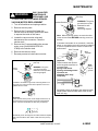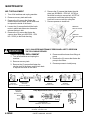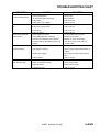
1
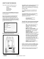
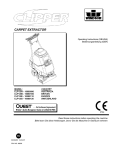
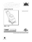
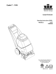
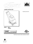
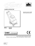
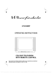
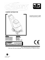
CARPET EXTRACTOR
Operating Instructions (USA)
Bedienungsanleitung (GER)
MODEL:
CDT7IA/10080050
CDT7IB/10080060
CDT7IE/10080070
CDT7IS/10080080
COUNTRY
AUSTRALIA
BRITIAN
EUROPE
SWITZERLAND
IPX4
Read instructions before operating the machine
Bitte lesen Sie diese Anleitungen, bevor Sie die Maschine in Gebrauch nehmen
AF
86038340 04/19/07
PRV NO. 98707
MACHINE DATA LOG/OVERVIEW
MODEL _______________________________________
DATE OF PURCHASE __________________________
SERIAL NUMBER ______________________________
SALES REPRESENTATIVE # _____________________
DEALER NAME ________________________________
OPERATIONS GUIDE NUMBER ___________________
PUBLISHED __________________________________________
Copyright 2002 Windsor Industries, Printed in USA
YOUR DEALER
Name: __________________________________________________________________________________________________
Address: _______________________________________________________________________________________________
For the name and address of your dealer contact: Windsor Industries
Phone Number: _________________________________________________________________________________________
2ENG
CADET 86038340 04/19/07
TABLE OF CONTENTS
Machine Data Log/Overview (English). ........1
Machine Data Log/Overview (German). .......2
Table of Contents (English) ..........................3
Table of Contents (German) .........................4
HOW TO USE THIS MANUAL
How to use this Manual. ........................1-1ENG
SAFETY
GROUP PARTS LIST
Frame Assembly..........................................5-1
Brush Assembly...........................................5-3
Pump Assembly...........................................5-5
Vacuum Shoe Assembly .............................5-9
Control Panel Assembly ..............................5-11
Solution Tank Assembly ..............................5-13
Recovery Tank Assembly............................5-15
Suggested Spare Parts ...............................5-17
EC Declaration of Conformity ......................5-18
Important Safety Instructions .................2-1ENG
Hazard Intensity Level. ..........................2-2ENG
Safety Label Location. ...........................2-3ENG
OPERATIONS
Technical Specifications. .......................3-1ENG
Controls/Components ............................3-2ENG
Filling the Solution Tank ........................3-5ENG
Machine Operation. ...............................3-6ENG
Cleaning Procedure. ..............................3-9ENG
Accessory Tool Usage........................3-10ENG
MAINTENANCE
Periodic Maintenance ............................4-1ENG
Daily/Regular Maintenance....................4-1ENG
Vacuum Motor Replacement. ................4-2ENG
Belt Replacement ..................................4-3ENG
Solution Pump Replacement. ................4-3ENG
Machine Troubleshooting ......................4-4ENG
Wiring Diagram ......................................4-5
CADET 86038340 04/19/07
3ENG
HOW TO USE THIS MANUAL
This manual contains the following sections:
-
-
HOW TO USE THIS MANUAL
SAFETY
OPERATIONS
MAINTENANCE
PARTS LIST
The HOW TO USE THIS MANUAL section will tell
you how to find important information for ordering
correct repair parts.
Parts may be ordered from authorized Windsor
dealers. When placing an order for parts, the
machine model and machine serial number are
important. Refer to the MACHINE DATA box which
is filled out during the installation of your machine.
The MACHINE DATA box is located on the inside of
the front cover of this manual.
MODEL _____________________________________
The SAFETY section contains important information
regarding hazard or unsafe practices of the
machine. Levels of hazards is identified that could
result in product or personal injury, or severe injury
resulting in death.
The OPERATIONS section is to familiarize the
operator with the operation and function of the
machine.
The MAINTENANCE section contains preventive
maintenance to keep the machine and its
components in good working condition. They are
listed in this general order:
-
Vacuum Motor Replacement
Belt Replacement
Solution Pump Replacement
The PARTS LIST section contains assembled parts
illustrations and corresponding parts list. The parts
lists include a number of columns of information:
DATE OF PURCHASE ________________________
-
SERIAL NUMBER ____________________________
SALES REPRESENTATIVE # ___________________
-
DEALER NAME ______________________________
-
OPERATIONS GUIDE NUMBER __________________
PUBLISHED ________________________________
-
Copyright 2002 Windsor Industries, Printed in USA
The model and serial number of your machine is on
the bottom back-end of the machine.
-
-
REF – column refers to the reference
number on the parts illustration.
PART NO. – column lists the part
number for the part.
PRV NO. – reference number.
QTY – column lists the quantity of the
part used in that area of the machine.
DESCRIPTION – column is a brief
description of the part.
SERIAL NO. FROM – column indicates
the first machine the part number is
applicable to. When the machine design
has changed, this column will indicate
serial number of applicable machine.
The main illustration shows the most
current design of the machine. The
boxed illustrations show older designs. If
column has an asterisk (*), call
manufacturer for serial number.
NOTES – column for information not
noted by the other columns.
NOTE: If a service or option kit is installed on your
machine, be sure to keep the KIT INSTRUCTIONS
which came with the kit. It contains replacement
parts numbers needed for ordering future parts.
NOTE: The number on the lower left corner of the
front cover is the part number for this manual.
1-1ENG
CADET 86038340 04/19/07
IMPORTANT SAFETY INSTRUCTIONS
When using an electrical appliance, basic precaution
must always be followed, including the following:
READ ALL INSTRUCTIONS BEFORE USING THIS MACHINE.
This machine is for commercial use.
! WARNING:
To reduce the risk of fire, electric shock, or injury:
Connect to a properly grounded outlet. See Grounding Instructions.
Do not leave the machine unattended. Unplug machine from outlet when not in use and before
maintenance or service.
Use only indoors. Do not use outdoors or expose to rain.
Do not allow machine to be used as a toy. Close attention is necessary when used by or near
children.
Use only as described in this manual. Use only manufacturer’s recommended components and
attachments.
Do not use damaged electrical cord or plug. Follow all instructions in this manual concerning grounding
the machine. If the machine is not working properly, has been dropped, damaged, left outdoors, or
dropped into water, return it to an authorized service center.
Do not pull or carry machine by electrical cord, use as a handle, close a door on cord, or pull cord
around sharp edges or corners.
Do not run machine over cord. Keep cord away from heated surfaces.
Do not unplug machine by pulling on cord. To unplug, grasp the electrical plug, not the electrical cord.
Do not handle the electrical plug or machine with wet hands.
Do not operate the machine with any openings blocked. Keep openings free of debris that may reduce
airflow.
This machine is intended for cleaning carpet only.
Do not vacuum anything that is burning or smoking, such as cigarettes, matches, or hot ashes.
This machine is not suitable for picking up health endangering dust.
Turn off all controls before unplugging.
Machine can cause a fire when operating near flammable vapors or materials. Do not operate this
machine near flammable fluids, dust or vapors.
This machine is suitable for commercial use, for example in hotels, schools, hospitals,
factories, shops and offices for more than normal housekeeping purposes.
Maintenance and repairs must be done by qualified personnel.
If foam or liquid comes out of machine, switch off immediately.
SAVE THESE INSTRUCTIONS
CADET 86038340 04/19/07
2-1ENG
HAZARD INTENSITY LEVEL
The following symbols are used throughout this guide as indicated in their descriptions:
HAZARD INTENSITY LEVEL
There are three levels of hazard intensity identified by signal words -WARNING and CAUTION and FOR
SAFETY. The level of hazard intensity is determined by the following definitions:
! WARNING
WARNING - Hazards or unsafe practices which COULD result in severe personal injury or death.
! CAUTION
CAUTION - Hazards or unsafe practices which could result in minor personal injury or product or property
damage.
FOR SAFETY: To Identify actions which must be followed for safe operation of equipment.
Report machine damage or faulty operation immediately. Do not use the machine if it is not in proper
operating condition. Following is information that signals some potentially dangerous conditions to the
operator or the equipment. Read this information carefully. Know when these conditions can exist. Locate
all safety devices on the machine. Please take the necessary steps to train the machine operating
personnel.
FOR SAFETY:
DO NOT OPERATE MACHINE:
Unless Trained and Authorized.
Unless Operation Guide is Read and understood.
In Flammable or Explosive areas.
In areas with possible falling objects.
WHEN SERVICING MACHINE:
Avoid moving parts. Do not wear loose clothing; jackets, shirts, or sleeves when working on the
machine. Use Windsor approved replacement parts.
2-2ENG
CADET 86038340 04/19/07
SAFETY LABEL LOCATION
NOTE: These drawings indicate the location of safety labels on the CDT7//10080230. If, at any time, the labels
become illegible contact your Windsor representative for prompt replacement.
WARNING DECAL
86242230
PRV NO. 500009
CADET 86038340 04/19/07
2-3ENG
ACCESSORY TOOL USAGE
STEP
1
Use only one of the following
acceptable accessory tools.
86000000 – PRV NO. DDH
86031540 – PRV NO. 39504
86041180 – PRV NO. ESW
86000050 – PRV NO. SPW
86000020 – PRV NO. HT
Pull back collar and insert over
machine mounted fitting, then
release collar to lock into place.
STEP
2
PUMP
VACUUM
ON
STEP
3
ON
Lift door on front of vacuum shoe
and insert 1 ½ inch hose cuff into
hole.
Turn on Pump and Vacuum Switch.
Note: Be sure
intermittent/continuous switch is in
center (off) position and brush is in
storage position.
OFF
STEP
4
Squeeze handle on accessory tool
to begin cleaning.
CADET 86038340 04/19/07
3-10ENG
TECHNICAL SPECIFICATIONS
POWER TYPE
GENERAL DIMENSIONS/WEIGHT
ELECTRICAL: 230-240 V, 7 A, 50 HZ
Vacuum shoe: 17” (43.18 cm) cast
aluminum with spring loaded down
pressure
ELECTRIC VACUUM MOTOR: (1) –3 stage, 1 hp, 99
cfm (2.80 cubic meters/min.) Waterlift –117” (297cm)
WHEELS: (2) 10” dia. (25 cm) wheels
by 2”
BRUSH: (1) 15” (38.1 cm.)
SOLUTION PUMP: 100 PSI, diaphragm style, internal
bypass
WEIGHT: 92lbs. (42kg)
LENGTH: 41” (104 cm)
SOLUTION CAPACITY: 7 gallons (26.5ltr)
HEIGHT: 34” (86.36 cm)
RECOVERY CAPACITY: 7 gallons (26.5ltr)
WIDTH: 17.5” (44.45 cm)
BRUSH SPEED: 1000 rpm
SOLUTION SPRAY: 2 quick change
jets.
POWER CABLE: 50’ (12.7 m) (1mm)
34”
(86.36cm)
41”
(104cm)
3-1ENG
17.5”
(44.45cm)
CADET 86038340 04/19/07
CONTROLS/COMPONENT LOCATIONS
3
5
4
1
1.
Main Handle. Used to pull and maneuver
machine.
2.
Electrical Cord.
3.
Pump Switch. Turns on pump and enables
spray.
4.
Brush/Spray switch. Turns on brush motor
and activates electro-valve to dispense
solution to floor through jets. Intermittent, off,
and continuous settings.
5.
Vacuum Motor Switch. Turns on vacuum
motor
6.
Brush Motor Circuit Breaker. 4 amp.
Breaker protecting brush motor.
7.
Vacuum Motor Circuit Breaker. 7 amp.
Breaker protecting vacuum motor.
8.
Recovery Dump Hose. Facilitates draining
dirty cleaning solution.
9.
Solution Dump Hose. Facilitates draining
excess cleaning solution from solution tank.
7
6
2
8
9
CADET 86038340 04/19/07
3-2ENG
CONTROLS/COMPONENT LOCATIONS
1.
Solution Accessory Tool Hookup. Used for
various auxiliary cleaning tools.
2.
Vacuum Hose Door. Used to connect
various auxiliary 1-1/2 inch cleaning tool
vacuum hoses.
3.
Brush Height Adjustment. Used to regulate
brush height from storage position to various
carpet heights.
4.
Recovery Tank. Used to collect dirty
cleaning solution.
5.
Solution Tank. Used to hold cleaning
solution.
6.
Recovery Tank Dome.
7.
Vacuum Shoe.
8.
Brush Housing.
9.
Front Lifting Handle.
10.
Cleaning Solution Filter.
10
1
9
2
3
6
4
5
7
8
3-3ENG
CADET 86038340 04/19/07
CONTROLS/COMPONENT LOCATIONS
1.
Solution Intake Cover.
2.
Vacuum Intake Cover.
3.
Float Shut-Off.
4.
Clean-Out Opening.
5.
Pour Spout.
6.
Lift Handle.
6
1
2
4
6
5
3
CADET 86038340 04/19/07
3-4ENG
FILLING OPERATIONS
STEP
1
RECOVERY TANK
Remove recovery
tank
SOLUTION
TANK
STEP
2
FILL LINE
Add water
7 gal.
(26.5 ltr.)
140°F (60°C)
STEP
3
FILLING THE CADET
NOTE: Use clean bucket of water to fill solution tank
Do not put defoamer, solvents, spotter or
prespray chemicals in the solution tank.
7 – 14oz.
(207ml – 414ml)
Add cleaning
chemical
Do not allow water to spill into vacuum motor inlet. Dry
spillage from top of solution tank before replacing
recovery tank.
CHEMICALS
Suitable Chemicals
Alkalis
Detergents
Hydroxides
Soaps
Vinegar
Non-Compatible Chemicals
Aldehydes
Aromatic Hydrocarbons
SP Butyls
Carbon Tetrachloride
Clorox*
Chlorinated Bleaches
Chlorinated Hydrocarbons
Lysol*
Methyl Ethel Ketone (MEK)
Perchorethylene (perc)
Phenolics
Trichlorethylene
D-Limonene
STEP
4
* Product Trademark Names
3-5ENG
CADET 86038340 04/19/07
Replace recovery
tank
OPERATIONS
STEP
1
STEP
2
STEP
3
1/8in
(3mm)
CORRECT
Remove electrical cord and literature
from recovery tank. Fill solution tank
(see filling operations, page 3-5).
Plug cord into grounded outlet. Note:
Be sure dome is seated on recovery
tank, and float shut-off is installed
correctly.
Adjust brush to proper setting. Note:
For good operation the brush must
skim the carpet. If circuit breaker
trips raise brush to prevent damage
to motor or carpet.
INCORRECT
STEP
PUMP
ON
VACUUM
4
Turn on both Vacuum and Pump
motor switches (“ON”=“I”).
ON
CADET 86038340 04/19/07
3-6ENG
OPERATIONS
Tip machine back by main handle
to move to starting point.
STEP
Lower machine to floor.
STEP
Select intermittent or continuous
switch setting to turn on brush and
start solution spray.
The intermittent setting requires the
operator to hold the switch in the
“on” position with the thumb, and is
typically used in small areas where
short cleaning passes are made.
The continuous setting allows the
operator to set the switch in the “on”
position with one touch, and is
typically used in large areas where
long cleaning passes are made.
STEP
3-7ENG
5
6
INTERMITTENT
7
CONTINUOUS
CADET 86038340 04/19/07
CLEANING PROCEDURE
STEP
1
STEP
2
1ft.
(30cm)
Release intermittent setting or turn
off continuous setting on
brush/spray switch approximately 1
foot before ending cleaning pass.
OFF
STEP
1in.
(25mm)
3
SOLUTION
INTAKE COVER
VACUUM
INTAKE COVER
Start at wall closest to power outlet.
Pull straight back without pushing
down on handle.
STEP
4
Push down on handle to raise
vacuum shoe and brush before
moving to the next cleaning pass.
Overlap brush contact area a
minimum of 1 inch on the right
(close cleaning) side of machine.
Overlap a minimum of 2 inches on
the left (drive belt) side of machine.
During operation, observe the following:
The Cadet is equipped with clear
internal covers to facilitate operator
viewing of dirty solution and vacuum air
flow.
During operation, observe the vacuum
intake cover. Large amounts of water or
foam entering the vacuum system can
damage the vacuum motor. If you
notice either condition, shut down the
machine immediately. Empty recovery
tank and/or add defoamer to recovery
tank.
CADET 86038340 04/19/07
3-8ENG
CLEANING PROCEDURE
Use right side of machine for
cleaning against walls.
STEP
After cleaning, turn off all controls,
return brush to storage position and
carefully unplug machine.
STEP
5
6
OFF
OFF
OFF
To speed drying, use a
Windblower™ fan.
STEP
Empty recovery tank by releasing
dump hose. Use a hose with cold
water to clean out the recovery tank.
Also drain solution tank after each
use.
STEP
7
8
RECOVERY
DRAIN
SOLUTION
DRAIN
3-9ENG
CADET 86038340 04/19/07
MAINTENANCE
PERIODIC MAINTENANCE
DAILY / REGULAR MAINTENANCE
Twice a month, flush a white vinegar solution
(One quart vinegar to two gallons of water) or
anti-browning solution (mixed as directed)
through the extractor. This will prevent build-up
of alkaline residue in the system. If spray jets
become clogged, remove the spray tips, wash
them thoroughly, and blow-dry.
Before making any adjustments or repairs to
the machine, disconnect the power cord from
electrical source.
NOTE: Do not use pins, wire, etc. to clean
nozzles as this could destroy spray pattern.
Periodically inspect all hoses, electrical cables
and connections on your machine. Frayed or
cracked hoses should be repaired or replaced
to eliminate vacuum or solution pressure loss. If
the cable insulation is broken or frayed, repair
or replace it immediately. Don’t take chances
with electrical fire or shock.
1. Empty unused cleaning solution from the
solution tank.
2. Inspect and clean filter screen in solution
tank.
3. Flush pumping system with 4 or 7 liters of
clean, hot water.
4. After each use, rinse tank with fresh water.
Periodically inspect the recovery tank and
decontaminate if necessary, using a
Hospital Grade Virucide or a 1-10 bleach to
water solution. Waste water should be
disposed of properly.
5. Check for and remove any lint or debris
around vac shoe.
6. Check spray jets for full spray pattern.
7. Remove lint and dirt build-up from brush
and housing.
NOTE: Brush removal.
A. To remove brush, grab and pull brush
out from end opposite drive belt
(operator’s right). Remove other end
from brush driver.
B. To install brush, line up slots in brush
core with pin in driver on drive belt side
(operator’s left) and push brush onto
driver. Then snap bearing end (opposite
end) of brush into retaining clip.
8. Check cooling air screen (located on frame
behind left wheel) for lint or debris.
9. Check float and shut-off screen and clean
as necessary.
NOTE: Always store machine with brush in
“Store” position.
4-1ENG
CADET 86038340 04/19/07
MAINTENANCE
ONLY QUALIFIED
MAINTENANCE
PERSONNEL ARE
TO PERFORM THE FOLLOWING REPAIRS.
Vac Motor Carbon Brushes Replacement (Ametek)
End Cap
VACUUM MOTOR REPLACEMENT
Carbon Brushes
! WARNING:
1. Turn off all switches and unplug machine.
2. Remove recovery tank.
3. Remove the (2) screws that fasten the
solution tank to the frame, and tilt tank back
to expose the inside of the frame.
4. Locate the vacuum motor wires and
disconnect at the connector. Close the
solution tank.
5. Remove the (6) screws holding the vacuum
motor cover (p/n 86003080-PRV NO.
27809) to the solution tank.
6. Remove the vacuum motor.
7. Reverse process to install vacuum motor.
Vacuum Motor Carbon Brushes Replacement (Windsor)
End Cap
Carbon
Brushes
WARNING: The green
ground wire must be
attached for safe operation.
See wiring diagram.
WARNING: The green
ground wire must be
attached for safe
operation.
See wiring diagram.
Note: When replacing carbon vac motor brushes
loosen wire terminal BEFORE removing screws on
bracket.
If armature commutator is not concentric, extremely
pitted, or grooved the motor will need to be replaced
or sent to a qualified service center to restore vac
performance.
Wire Terminal
Wire
Terminal
Important:
These brushes wear quicker
as the length shortens due to
increased heat.
Spring inside brush
housing will damage motor
if brushes are
allowed to wear away
completely.
If armature commutator is grooved, extremely pitted or not
concentric, the motor will need to be replaced or sent to a
qualified service center.
Note:
Place
stop in
groove.
3/8
Periodically check the length of the carbon brushes.
Replace both carbon brushes when either is less
than 3/8" long.
Important:
These brushes wear quicker as the length shortens due to
increased heat. Spring inside brush housing will damage
motor if brushes are allowed to wear away completely.
3 [9.5mm]
8
Periodically check the length of the carbon brushes. Replace
both carbon brushes when either is less than 3/8" (9.5mm)
long.
CADET 86038340 04/19/07
4-2ENG
MAINTENANCE
BELT REPLACEMENT
1. Turn off all switches and unplug machine.
2. Remove recovery tank and brush.
3. Remove the (2) screws that fasten the
solution tank to the frame, and tilt tank back
to expose the inside of the frame.
6. Remove the (3) screws that fasten the side
plate (p/n 86249420 – PRV NO. 62759) to
the brush housing to remove belt. NOTE: All
components associated with driving the
brush will come out with the side plate.
7. Reverse process to install belt.
4. Loosen the (4) screws that hold the brush
motor in place and slide motor forward to
release tension in belt.
86249420
PRV
NO. 62759
62759
5. Remove the (2) screws that fasten the
vacuum shoe links (p/n 86227350 – PRV
NO. 05016) to the brush housing.
! WARNING:
86227350
05016
PRV NO. 05016
ONLY QUALIFIED MAINTENANCE PERSONNEL ARE TO PERFORM
THE FOLLOWING REPAIRS.
SOLUTION PUMP REPLACEMENT
4. Remove solution hoses from fittings in
pump.
1. Turn off all switches and unplug the
machine.
5. Remove the (2) screws that fasten the
pump to the frame.
2. Remove recovery tank.
6. Reverse process to install pump.
3. Remove the (2) screws that fasten the
solution tank to the frame, and tilt tank back
to expose the inside of the frame.
Pump Replacement Parts for Shurflo 100 psi (86026400-PRV NO. 65254)
Pump Head
86251040
PRV NO. 65187
Pressure Switch
86161980
PRV NO. 42-809332
Pump Hsng
86288790
PRV NO. 41387
Valve Asm
86258830
PRV NO. 84161
Pump Replacement Parts for Flojet 73 psi (86006110-PRV NO. 65189)
Pump Repair Kit
86004600 – PRV NO. 47176
Hsng/Pump Repair Kit
86136040 – PRV NO. 47350
4-3ENG
Diaphram
86235100
PRV NO. 29206
CADET 86038340 04/19/07
TROUBLESHOOTING CHART
PROBLEM
CAUSE
SOLUTION
1. Is the cord plugged in.
1. Plug in cord.
2. Circuit breaker tripped in building.
2. Reset breaker
3. Faulty switch.
3. Call for service.
4. Faulty power cord or pigtail.
4. Call for service.
Vacuum Motor Will Not
1. Vacuum circuit breaker tripped.
1. Reset breaker
Run
2. Faulty main vacuum switch.
2. Call for service.
3. Loose wiring.
3. Call for service.
4. Faulty vac motor.
4. Call for service.
Vacuum Motor Runs But
1. Debris lodged in vac shoe.
1. Remove debris from vac shoe.
Suction Is Poor
2. Dome gasket defective or missing.
2. Replace as necessary.
3. Vacuum hose cracked or hose cuff loose.
3. Replace or repair as necessary.
4. Recovery tank full / float ball stuck in the up
4. Turn off vac motor. Drain and rinse
No Power, Nothing Runs
recovery tank.
position.
Poor Or No Water Flow
1. Main pump switch off.
1. Turn on.
(Carpet Is Streaky)
2. Jets clogged or missing.
2. Clean using a vinegar /water solution or
replace.
3. Solution filter clogged.
3. Drain solution tank and clean solution
filter.
Brush Does Not Spin
4. Faulty solenoid.
4. Call for service.
1. Brush switch off.
1. Turn on brush switch.
2. Brush circuit breaker tripped
2. Reset circuit breaker.
3. Brush belt broken.
3. Replace as necessary.
4. Faulty brush motor.
4. Call for service.
CADET 86038340 04/19/07
4-4ENG
WIRING DIAGRAM
86003650
PRV NO. 34362
86268750
PRV NO. 88567
86268750
PRV NO. 88567
86268900
PRV NO. 88655
86268750
PRV NO. 88567
86004480
PRV NO. 41353
86268900
PRV NO. 88655
4-5ENG
CADET 86038340 04/19/07
86268350
PRV NO. 88270
86001240
PRV NO. 14020
86268750
PRV NO. 88567
NOTES
CADET 86038340 04/19/07
4-6ENG