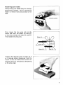
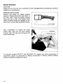
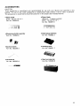
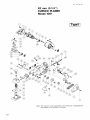
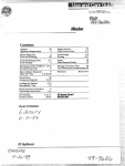
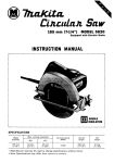
1
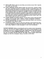
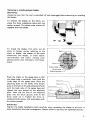
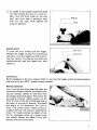
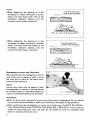
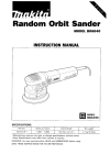
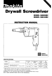
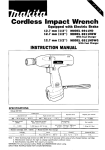
Curved Planer
82 mm (3-1/4")
MODEL 1001
INSTRUCTION MANUAL
Planing w i d t h
82 mm 13~114")
Planing depth
N o load speed
IRPMI
3 mm 1118"l
12,000
Overall length
370 mm 1,14~1/2"1
Net weight
6.0 kg 113.2 lbsl
IMPORTANT SAFETY INSTRUCTIONS
WARNING: When using electric tools, basic safety precautions should always
be followed t o reduce the risk of fire, electric shock, and personal injury, including the following:
READ ALL INSTRUCTIONS.
1. KEEP WORK AREA CLEAN. Cluttered areas and benches invite injuries.
2. CONSIDER WORK AREA ENVIRONMENT. Don't use power tools in damp
or wet locations. Keep work area well lit. Don't expose power tools t o rain.
Don't use tool in presence of flammable liquids or gases.
3. KEEP CHILDREN AWAY. All visitors should be kept away from work area.
Don't let visitors ccntact tool or extension cord.
4.STORE IDLE TOOLS. When not in use, tools should be stored in dry, and high
or locked-up place - out of reach of children.
5. DON'T FORCE TOOL. It will do the job better and safer at the rate for which
it was intended.
6. USE RIGHT TOOL. Don't force small tool or attachment t o do the job of a
heavy-duty tool. Don't use tool for purpose not intended.
7. DRESS PROPERLY. Don't wear loose clothing or jewelry. They can be caught
in moving parts. Rubber gloves and non-skid footwear are recommended
when working outdoors. Wear protective hair covering t o contain long hair.
8.USE SAFETY GLASSES. Also use face or dust mask if cutting operation is
dusty.
9. DON'T ABUSE CORD. Never carry tool by cord or yank it t o disconnect from
receptacle. Keep cord from heat, oil, and sharp edges.
IO. SECURE WORK.
Use clamps or a vise t o hold work. It's safer than using
your hand and it frees both hands t o operate tool.
1 1 . DON'T OVERREACH. Keep proper footing and balance at all times.
12. MAINTAIN TOOLS WITH CARE. Keep tools sharp and clean for better and
safer performance. Follow instructions for lubricating and changing accessories. Inspect tool cords periodically and if damaged, have repaired by authorized service facility. Inspect extension cords periodically and replace if
damaged. Keep handles dry, clean, and free from oil and grease.
13. DISCONNECT TOOLS. When not in use, before servicing, and when changing accessories, such as blades, bits, cutters.
14.REMOVE ADJUSTING KEYS AND WRENCHES. Form habit of checking t o
see that keys and adjusting wrenches are removed from tool before turning
it on.
15. AVOID UNINTENTIONALSTARTING. Don't carry plugged-in tool with finger
on switch. Be sure switch is OFF when plugging in.
16. OUTDOOR USE EXTENSION CORDS. When tool is used outdoors, use only
extension cords intended for use outdoors and so marked.
L
17. STAY ALERT. Watch what you are doing, use common sense. Don’t operate
tool when you are tired.
18. CHECK DAMAGED PARTS. Before further use of the tool, a guard or other
part that is damaged should be carefully checked t o determine that it will
operate properly and perform its intended function. Check for alignment of
moving parts, binding of moving parts, breakage of parts, mounting, and any
other conditions that may affect its operation. A guard or other part that
is damaged should be properly repaired or replaced by an authorized service center unless otherwise indicated elsewhere in this instruction manual.
Have defective switches replaced by authorized service center. Don’t use
tool if switch does not turn it on and off.
19. GUARD AGAINST ELECTRIC SHOCK. Prevent body contact with grounded
surfaces. For example; pipes, radiators, ranges, refrigerator enclosures.
20. PROPER GROUNDING. This tool should be grounded while in use t o protect
the operator from electric shock.
21. EXTENSION CORDS: Use only three-wire extension cords which have threeprong grounding-type plugs and three-pole receptacles which accept the
tool’s plug. Replace or repair damaged or worn cord immediately.
VOLTAGE WARNING: Before connecting the tool t o a power source (receptacle,
outlet, etc.) be sure the voltage supplied is the same as that specified on the
nameplate of the tool. A power source with voltage greater than that specified
for the tool can result in SERIOUS INJURY t o the user - as well as damage t o
the tool. If in doubt, DO NOT PLUG IN THE TOOL. Using a power source with
voltage less than the nameplate rating is harmful t o the motor.
3
ADDITIONAL SAFETY RULES
1. Rags, cloth, cord, string and the like should never be left around the work
area.
2. Avoid cutting nails. Inspect for and remove all nails from the workpiece before operation.
3. Handle the blades very carefully.
4. Be sure the blade installation bolts are securely tightened before operation.
5. Hold the tool firmly with both hands.
6. Keep hands away from rotating parts.
7. Before using the tool on an actual workpiece, let it run for a while. Watch
for vibration or wobbling that could indicate poor installation or a poorly
balanced blade.
8. Make sure the blade is not contacting the workpiece before the switch is
turned on.
9. Wait until the blade attains full speed before cutting.
IO. Keep at least 200 m m (8") away from the tool at all times.
1 1 . Always switch off and wait for the blades t o come t o a complete stop before any adjusting.
12. Never stick your finger into the chip chute. Chute may jam when cutting
damp wood. Clean out chips with a stick.
13. Do not leave the tool running. Operate the tool only when hand-held.
14. When leaving the planer, switch off and set it with the front base up on a
wooden block, so that the blades do not contact anything.
15. Always change both blades or covers on the drum, otherwise the resulting
imbalance will cause vibration and shorten tool life.
SAVE THESE INSTRUCTIONS.
4
Removing or installing planer blades
WARNING :
Always be sure that the tool is switched off and unplugged before removing or installing
the blades.
To remove the blades on the drum, unscrew the three installation bolts with the
socket wrench. The drum cover comes off
together with the blades.
To install the blades, first clean out all
chips or foreign matter adhering to the
drum or blades. Use blades of the same
dimensions and weight, or drum oscillationhibration will result, causing poor
planing action and, eventually, tool breakdown.
I
1
Place the blade on the gauge base so that
the blade edge i s perfectly flush with the
inside edge of the gauge plate. Place the
adjusting plate on the blade, then simply
press in the heel of the adjusting plate flush
with the back side of the gauge base and
tighten the two screws on the adjusting
plate. Now slip the heel of the adjusting
plate into the drum groove, then fit the
drum cover on it. Tighten the three installation bolts evenly and alternately with
the socket wrench.
Eo1t
Adjusting p l a t e d
I
WARN ING :
Tighten the blade installation bolts carefully when attaching the blades to the tool. A
loose installation bolt can be dangerous. Always check to see they are tightened securely.
5
Adjusting depth of cut
Depth of cut may be adjusted by simply
turning the knob on the front of the tool.
Adjusting front base
1. To create a curved surface, loosen the
wing nut. For a concave planing job,
raise the front base; for a convex planing job, lower the front base. In either
case, the front base must be aligned
with the cutting line. Then tighten the
wing nut securely.
NOTE :
As explained later, although the objective is to cut until the cutting line is
eventually reached, the planing must
take place gradually.
6
I
I
Convex
Cutting line
I
I
-
w
\
WlnO nut
Concave
Cutting line
\
2. To create a flat surface, loosen the wing
nut after setting the tool on a level surface. Turn the front knob on the tool
until the front base is perfectly level
with the rear base. Then tighten the
wing nut securely.
I
F
Wing n u t
Switch action
To start the tool, simply pull the trigger.
Release the trigger to stop. For continuous
operation, pull the trigger and then push in
the lock button. To stop the tool from the
locked position, pull the trigger fully, then
release it.
WARNING:
Before plugging in the tool, always check to see that the trigger switch actuates properly
and returns to the "OFF" position when released.
Planing operation
First, rest the tool front base flat upon the
workpiece surface without the blades making any contact. Switch on and wait until
the blades attain full speed. Then move the
tool gently forward. Apply pressure on the
front of tool a t the start of planing, and a t
the back a t the end of planing. The speed
and depth of cut determine the kind of
finish. The power planer keeps cutting a t
a speed that will not result in jamming by
chips. For rough cutting, the depth of cut
can be increased, while for a good finish
you should reduce the depth of cut and
advance the tool more slowly.
7
NOTE :
*When beginning the planing of a flat
workpiece to obtain eventually a convex
shape, first take down both ends of the
workpiece, gradually planing until the
ultimate convex shape is achieved.
*When beginning the planing of a flat
workpiece to obtain eventually a concave
shape, first take down the middle of the
workpiece, gradually planing until the
ultimate concave shape i s achieved.
I
First take down both
ends of the workpiece
F i r s t take down the
middle of the workpiece
Shiplappingor corner cuts (flush cuts)
When performing the shiplapping or corner
cuts (flush cuts up against a wall), remove
the wing bolt to take off the drum cover,
allowing flush-sidework.
NOTE :
Corner cuts (flush cuts up against a wall)
are impossible, of course, if the tool cannot
be moved forward or backward because of
a wall or something blocking the tool path.
WARNING :
With the drum cover removed for corner cuts (flush cuts) or shiplapping, be very careful
not to touch the drum/blades or allow your clothing to be caught during operation.
After performing the shiplapping or corner cuts (flush cuts), ALWAYS RE-INSTALL
THE DRUM COVER AND TIGHTEN THE WING BOLT SECURELY. Never forget to
switch off and unplug the tool, and wait for the blades to come to a complete stop
before re-installingthe drum cover.
8
Sharpening planer blades
I
Always keep your blades sharp for the best
performance possible. Use the sharpening
holder to remove nicks and produce a fine
edge.
First, loosen the two wing nuts on the
holder and insert the blades (A) and (B),
so that they contact the sides ( C ) and (D).
Then tighten the wing nuts.
Immerse the dressing stone in water for 2
or 3 minutes before sharpening.' Hold the
holder so that the blades both contact the
dressing stone for simultaneous sharpening
a t the same angle.
9
MAINTENANCE
CAUTION :
Always be sure that the tool is switched off and unplugged before attempting to perform
inspection or maintenance.
Replacingcarbon brushes
Remove and check the carbon brushes
regularly. Replace when they wear down to
the limit mark. Keep the carbon brushes
clean and free to slip in the holders. Both
carbon brushes should be replaced a t the
same time. Use only Makita carbon brushes.
/
Limit mark
Use a screwdriver to remove the brush
holder caps. Take out the worn carbon
brushes, insert the new ones and secure the
brush holder caps.
To maintain product SAFETY and RELIABILITY, repairs, any other maintenance or
adjustment should be performed by Makita Authorized or Factory Service Centers,
always using Makita replacement parts.
10
ACCESSORIES
CAUTION:
These accessories or attachments are recommended for use with your Makita tool specified in this
manual. The use of any other accessories or attachments might present a risk of injury to persons.
The accessories or attachments should be used only in the proper and intended manner.
0
Planer blade
(Material : Tungsten-carbide)
Width : 82 mm (3-1/4")
Part No. 793007-0
Planer blade
Width : 82 mm (3-1/4")
Part No. 793004-6
0
Sharpening holder assembly
Part No. 123004-6
0
Socket wrench
Part No. 782209-3
0
Screwdriver
Part No. 783002-8
0
0
0
0
Blade gauge assembly
Part No. 123062-2
Dressing stone
Part No. 794061-7
Steel carrying case
Part No. 181840-6
11
Jan
26-89 EN
82 mm (3-1/4")
CURVED PLANER
Model 1001
Note The switch, noise suppressor and other part configuratlons
may differ from country to country
12
MODEL 1 0 0 1
z:,
Jan - 2 6 - ' 8 9 EN
DESCRIPTION
ITEM
NO
NO
USED
33
34
35
36
31
38
3Y
40
41
42
43
44
45
46
41
48
49
50
51
52
53
54
55
56
51
58
59
60
61
62
63
64
65
1
1
DESCRIPTION
MACHINE
~
1
2
3
4
5
6
1
8
9
10
11
12
13
14
15
16
17
18
19
20
21
22
23
24
25
26
21
28
29
30
31
32
4
1
1
1
1
1
1
2
1
1
1
6
2
4
2
1
1
1
I
2
1
1
2
I
2
2
4
1
1
1
1
1
-
Pan Head Screw M 5 x 2 5 IWith Washer1
Bracket
Ball Bearing 6200LLB
Fan 80
ARMATURE ASSEMBLY
71
!With lfem 3
Flaf Washer 1 2
Ball Bearing 6201LLB
Pan Head Screw M 5 x 6 0 IWifh Washer)
FIELD ASSEMBLY
Rubber Pin 6
Rubber Pin 4
Hex Flange Head Bolt M 6 x 1 7
Drum Plate
Pan Head Screw M 4 x 5
Adlust Plate
Drum
Ball Bearing 600322
Rubber Pin 6
Cord
Pan Head Screw M 4 x 1 4 IWith Washerl
Strain Relief
Cord Guard
lnsulal~onWasher
Main Frame
Carbon Brush
Brush Holder Cap
Rivet 0 5
Wing Bo11 M 5 x 1 0
Spr~ngWasher 5
Drum Cover
spring P,n 8
Name Plate
80
___
1
1
1
Set Bo11 M 8
Knob 50
Flaf Washer I O
Noise Suppressor
1
1
Swttch
Pan Head Screw M 4 x 8 IWith Washer1
Handle Cover
Countersunk Head Screw M 4 x 3 0 IWith Washer]
Pan Head Screw M 4 x 3 0 !With Washeri
Bell cover
Poly V Belt 6 285
V Pulley 6 23L
Pan Head Screw M 5 x 1 0 IWith Washer1
Bearing Retainer 44
V Pulley 6 - 3 0
Pan Head Screw M 4 x 2 5 IWNth Washer)
D W tiouslny
~
Ball Bearing 6001LLB
Rubber Pin 4
1
Retaining Ring R
1
1
Wing Nu! M 8
Spring Washer 8
F l a f Washer 8
Bellows
1
1
3
2
1
1
1
2
1
1
4
1
1
1
2
4
1
1
1
1
1
1
1
-
28
PreSSwe Plate
Pan Head Screw M 4 x 1 0 IWith Washer1
From B o x
Compression Sprinq 1 1
Rubber Pdckinq
Sprinq Pin 5 24
:roll, Base
:hip Cover
>an Head Screw M 5 x 1 4 !With Washerl
Note The switch noise suppressor and other part spechcations may differ from country 10 country
13
14
Makita Corporation
3-11-8, Sumiyoshi-cho,
Anjo, Aichi 446 Japan
883000A0
PRINTED IN JAPAN
I991 - 1 0 E