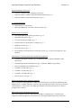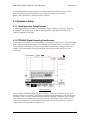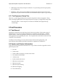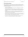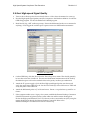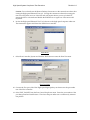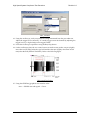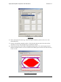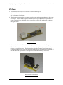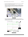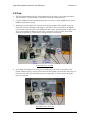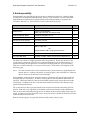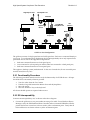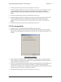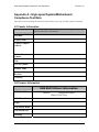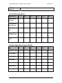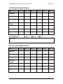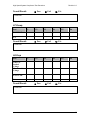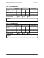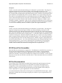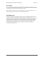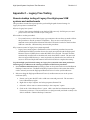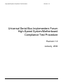
1
High Speed System Compliance Test Procedure
Revision 1.0
Universal Serial Bus Implementers Forum
High-Speed System/Motherboard
Compliance Test Procedure
Revision 1.0
January, 2004
1
Revision History
Rev
Date
Filename
0.91
Mar-15-2002
HS System Test.DOC
Preliminary review release
0.95
Jul-19-2002
HS System Test.DOC
Revised for 3rd Test House Use
0.96
Sept-9-2002
HS System Test.DOC
Added Legacy free test instructions
0.97
Dec-3-2002
HS System Test.DOC
0.98
Dec-15-2002
HS System Test.DOC
1.0 RC1
January 2004
HS System Test RC1.DOC
Comments
Formatting and Typo corrections
Added directions for setting up remote connection for
legacy free testing & matlab setup instructions.
Update to new gold tree and interop procedure
Update to require XP Professional only
Changed contact email
Please send comments via electronic mail to [email protected]
USB-IF High-speed System Electrical Test Procedure
© Copyright 2004, USB Implementers Forum, Inc.
All rights reserved.
High Speed System Compliance Test Procedure
Revision 1.0
DISCLAIMER OF WARRANTIES
THIS SPECIFICATION IS PROVIDED “AS IS” AND WITH NO WARRANTIES OF ANY KIND,
EXPRESS OR IMPLIED, INCLUDING, WITHOUT LIMITATION, NO WARRANTY OF
NONINFRINGEMENT, NO WARRANTY OF MERCHANTABILITY, NO WARRANTY OF
FITNESS FOR A PARTICULAR PURPOSE, NO WARRANTY OF TITLE, AND NO WARRANTY
ARISING OUT OF ANY PROPOSAL, SPECIFICATION, OR SAMPLE, ALL OF WHICH
WARRANTIES ARE EXPRESSLY DISCLAIMED.
WITHOUT LIMITING THE GENERALITY OF THE FOREGOING, USB-IF AND THE AUTHORS
OF THE SPECIFICATION DO NOT WARRANT OR REPRESENT THAT USE OF THE
SPECIFICATION WILL NOT INFRINGE THE INTELLECTUAL PROPERTY RIGHTS OF
OTHERS. USERS OF THE SPECIFICATIONASSUME ALL RISK OF SUCHINFRINGEMENT,
AND AGREE THAT THEY WILL MAKE NO CLAIM AGAINST USB-IF OR THE AUTHORS IN
THE EVENT OF CLAIMS OF INFRINGEMENT.
USB-IF IS NOT LIABLE FOR ANY CONSEQUENTIAL, SPECIAL OR OTHER DAMAGES
ARISING OUT OF THE USE OF THE SPECIFICATION.
LICENSE FOR INTERNAL USE ONLY
USB-IF HEREBY GRANTS A LICENSE TO REPRODUCE AND TO DISTRIBUTE THIS
SPECIFICATION FOR INTERNAL USE ONLY. NO OTHER LICENSE, EXPRESS OR IMPLIED,
BY ESTOPPEL OR OTHERWISE, IS GRANTED HEREWITH, AND NO LICENSE OF
INTELLECTUAL PROPERTY RIGHTS IS GRANTED HEREWITH.
All product names are trademarks, registered trademarks, or service marks of their respective
owners.
3
High Speed System Compliance Test Procedure
Revision 1.0
Table of Contents
1 Introduction...................................................................................................................... 5
2 Purpose............................................................................................................................. 5
3 Unit-Under-Test Requirements........................................................................................ 5
4 Equipment Required ........................................................................................................ 5
4.1 Equipment Setup....................................................................................................... 7
4.2 Operating Systems, Software, Drivers, and Setup Files ........................................... 8
4.3 Special Purpose Software ......................................................................................... 9
5 Test Procedure ............................................................................................................... 10
5.1 Test Record ............................................................................................................. 10
5.2 Vendor and Product Information ............................................................................ 10
5.3 Port Documentation ................................................................................................ 11
5.4 Host High-speed Signal Quality ............................................................................. 12
5.5 Full-speed Signal Quality ....................................................................................... 17
5.6 Low-speed Signal Quality....................................................................................... 23
5.7 Droop ...................................................................................................................... 27
5.8 Drop ........................................................................................................................ 30
5.9 Interoperability........................................................................................................ 32
Appendix A – High-speed System/Motherboard Compliance Test Data......................... 37
A1 Vendor Information................................................................................................. 37
A2 Product Information ................................................................................................ 37
A3 Port Documentation ................................................................................................ 38
A4 Host High-speed Signal Quality ............................................................................. 38
A5 Full-speed Signal Quality........................................................................................ 39
A6 Low-speed Signal Quality....................................................................................... 39
A7 Droop ...................................................................................................................... 40
A8 Drop ........................................................................................................................ 40
A9.1 S0 Interoperability................................................................................................ 41
A9.2 S1 Interoperability................................................................................................ 41
A9.3 S3 Interoperability................................................................................................ 42
A9.4 S4 Interoperability................................................................................................ 42
Appendix B – Certification Guidelines............................................................................. 43
B1 Submission Guidelines:........................................................................................... 43
B2 Off-board Port Assemblies...................................................................................... 44
B3 Port Documentation................................................................................................. 44
Appendix C – Legacy Free Testing .................................................................................. 46
Remote desktop testing of Legacy Free High-speed USB systems and motherboards 46
4
High Speed System Compliance Test Procedure
Revision 1.0
1 Introduction
The USB-IF High-speed System/Motherboard Compliance Test Procedure is developed by
the USB 2.0 Compliance Committee under the direction of USB-IF, Inc
The High-speed System/Motherboard Compliance Test Procedure is a test procedure designed
to be use for logo compliance test of PC system or motherboard implemented an EHCI host
controller that has successfully obtained the logo certification. The procedure is streamlined
with the removal of tests that are redundant with a known-good EHCI host controller. The
main goal of this procedure is to ensure the proper implementation of the system and
motherboard USB design. This procedure cannot be used for the compliance test of system or
motherboard with an unproven EHCI host controller.
2 Purpose
This USB-IF High-speed Compliance Test Procedure documents a series of tests used to evaluate
PC systems or motherboard with High-speed USB host controller that has obtained Hi-speed
logo status. These host controllers (EHCI host controllers) must either be integrated into the
motherboard chipset, or is a discrete host controller implemented onto the motherboard (i.e.
EHCI PCI adapter is excluded). This streamlined procedure affords a set of comprehensive tests
to ensure the minimum USB electrical integrity. It does not address other system functionality
like proper ACPI implementation. Although the drop and droop test of power delivery is
covered, this procedure does not exhaustively verify proper power delivery implementation such
as seamless power plane switching to support S3.
System or motherboard with new USB silicon must complete a set of more exhaustive compliance
tests. Please refer to the Compliance area of USB-IF website for detail.
3 Unit-Under-Test Requirements
The nature of system of motherboard integration for final product introduces a level of
configuration complexity not seen on hub, device, or host add-in card. Appendix B provides
some guidance such that the compliance test may be properly be carried out on a product family.
Please familiar yourself with this guidance on the submission configuration and test
documentation requirements.
4 Equipment Required
The commercial test equipment listed here are based on positive experience by the USB-IF
members in executing the USB high-speed electrical tests. This test procedure is written with a
set of specific models we use to develop this procedure. In time, there will be other equivalent or
better test equipment suitable for use. Some minor adaptation of the procedure will be required
in those cases.
5
High Speed System Compliance Test Procedure
Revision 1.0
Digital Sampling Oscilloscope:
•
Tektronix TDS694C digital sampling oscilloscope
•
Tektronix P6247 or P6248 or equivalent differential probe, qty = 1
•
Tektronix P6245 or equivalent FET probes, qty = 2
3 ½ Digital Multimeter
•
Fluke Model 77 or equivalent
•
Mini-clip DMM lead – one each of black and red color
USB Electrical Test Fixtures
•
Host high-speed signal quality test fixture, qty = 1
•
Disconnect test fixture, qty = 1
•
5V test fixture power supply, qty = 1
•
Female Serial B to female Serial A adaptor, qty = 1
•
SqiDD test fixture, qty = 1
•
Droop test fixture, qty = 1
•
Drop Dummy Load test fixture, 1 fixture per 2 ports (e.g. a 6-port system requires 3 test
fixtures)
Miscellaneous Certified Cables and Certified USB Peripherals
•
Certified High-speed USB Hub, qty = 5 (Belkin F5U221, or IOGear GUH224 or other
equivalent)
•
Certified High-speed USB Hard Drive, qty = 5 (Maxtor 3000LE or equivalent)
•
Microsoft Intellimouse USB Mouse, qty = 1
•
Certified 5 m USB cable, qty = 6
•
Certified 1 m USB cable, qty = 1
•
Certified 1.5 m USB cable, qty = 1
•
EIA AC power cord, qty = 2
High-speed Signal Quality Analysis Computer
This is a computer running Windows 2000 or XP Professional OS, and has the GPIB-DAQ and
Mathworks, Inc.'s Matlab installed. It retrieves the captured data from the oscilloscope through
a GPIB interface. Please refer to the High-speed Electrical Test Setup Instruction for steps to
configure this computer.
High-speed System/Motherboard Under Test
This is the computer under test with integrated USB 2.0 compliance host. The OS on this
computer is Microsoft Windows XP Professional. The High-speed Electrical Test Tool must
6
High Speed System Compliance Test Procedure
Revision 1.0
first be installed before performing the tests outlined in this document. Please refer to the
High-speed Electrical Test Setup Instruction for steps to configure this computer.
NOTE: Microsoft Windows XP Professional is required.
4.1 Equipment Setup
4.1.1 Test Equipment Setup Diskette
A setup floppy diskette is needed for the TDS 694C digital sampling oscilloscope. The setup
file simplifies equipment setup. Insert the Scope Tek 694C setup floppy diskette into the
Tektronix TDS694C oscilloscope.
4.1.2 TDS694C Digital Sampling Oscilloscope
Turn on the oscilloscope to allow for 10 minutes of warm up time prior to use. Perform the signal
path compensation procedure built into the TDS694C (in the Utility menu). During use, re-run
the signal path compensation procedure if the ambient temperature has changed more than 5
degrees. The compensation should be performed with the probes disconnected from the
oscilloscope.
Probe Calibration
Attach a P6247 or P6248 differential probe to Channel-1. Attach two P6245 FET probes, one to
Channel-2 and one to Channel-3. The probe assignment will be used through out the entire test
procedure. These two single-ended FET probes must be calibrated to minimize gain and offset
errors. Run the probe compensation procedure from the Vertical menu of the oscilloscope for
Channel 2 and Channel 3. If a FET probe has been removed from the oscilloscope, the probe
compensation routine should be run before use.
7
High Speed System Compliance Test Procedure
Revision 1.0
Probe Calibration
The offset errors of the differential probe will be compensated later as a part of the test procedure
process.
For P6247/P6248 differential probes, the following setting (on the probe) will be used through
out the entire test procedure:
• DC Reject <OFF>
(P6247 only)
• BW <Full>
(P6247 only)
• Attenuation <÷1>
NOTE: In certain test situation, there may not be a ground connection between the DSO and
the device under test. This may lead to the signal seen by the differential probe to be
modulated up and down due to mid frequency switching power supply (e.g. notebook
computer running on AC power). Connecting the DSO ground to the DUT ground will
be required to establish a common ground reference.
4.2 Operating Systems, Software, Drivers, and Setup Files
4.2.1 Operation Systems
Microsoft Windows XP Professional is required on the high-speed computer under test.
Microsoft Windows 2000 or XP Professional is required on the High-speed Signal Quality
Analysis Computer. Please refer to the High-speed Electrical Test Setup Instruction for steps to
configure these computers.
If testing a Legacy free system, Microsoft Windows XP Professional will be required on the highspeed computer under test and the computer used to remotely invoke HSET. The Home version
of XP will not work for testing a legacy free system. Refer to appendix C for more details.
8
High Speed System Compliance Test Procedure
Revision 1.0
4.3 Special Purpose Software
The following special purpose software is required. Please refer to the High-speed Electrical Test
Setup Instruction for steps to configure these computers.
•
High-speed Electrical Test Tool Software – To be used in the high-speed computer under
test.
•
Proprietary EHCI Driver Stack - The High-speed Electrical Test Tool software requires the
use of a proprietary EHCI driver stack. The use of this proprietary EHCI driver stack
facilitates the electrical testing that requires direct control of the command registers of the
USB EHCI host controllers. The end result is much more robust test bed environment. Since
the proprietary EHCI driver stack is designed for debug and test validation purposes, this
driver stack does not support the normal functionality as found in the EHCI drivers from
Microsoft (or the device vendor). An automatic driver stack switching function has been
implemented into the High-speed Electrical Test Tool for easy switching between the
proprietary EHCI driver stack and that from Microsoft. Upon invocation of the HS
Electrical Test Tool software, the driver stack will automatically switch to the Intel
proprietary EHCI driver stack. Upon exit of the HS Electrical Test Tool software, the driver
stack will automatically switch to the Microsoft EHCI driver stack.
•
Matlab 6 – Data analysis programming software
It is necessary to select the “–nodesktop” option when invoking the Matlab software so
that the GPIB DAQ software can export the scope data directly to the Matlab command
line. The easiest way to do this is to perform the following steps:
o
Install Matlab
o
Create a desktop shortcut for Matlab.
o
Add the “-nodesktop” option to the Matlab shortcut target field as shown:
9
High Speed System Compliance Test Procedure
Revision 1.0
•
USB Electrical Test Analysis Scripts for Matlab 6 – For performing electrical signal quality
test on USB devices.
•
GPIB DAQ – This is developed by USB-IF for importing the digitized signal in TSV (Tab
Separated Value) file format from the DSO into the Matlab analysis script for signal analysis.
4.3.1 Test Equipment Setup Files
These are 3 ½ inch floppy diskettes that contain the setup files for the test equipment. Please
refer to the High-speed Electrical Test Setup Instruction for steps to configure these setup disks.
DSO Setup Disk – Contain setup files for Tektronix TDS694C DSO (Digital Storage
Oscilloscope).
5 Test Procedure
5.1 Test Record
Appendix A contains the test result entry form for this test procedure. Please make copies of
Appendix A for use as test record documentation for compliance test submission. All fields
must be filled in. Fields not applicable for the device under test should be indicated as N/A,
with appropriate note explaining the reason. The completed test result shall be retained for the
compliance test submission.
In addition to the hardcopy test record, the electronic files from the signal quality, and
power delivery (drop and droop) shall be retained for compliance test submission.
5.2 Vendor and Product Information
Collect the following information and enter into a copy of the test record in Appendix A before
performing any tests.
1.
Test date
2.
Vendor name
3.
Vendor address and phone, and the contact name
4.
Test submission ID number
5.
Product name
6.
Product model and revision
7.
USB silicon vendor name
8.
USB silicon model
9.
USB silicon part marking
10. USB silicon stepping
11. Test Conducted by
10
High Speed System Compliance Test Procedure
Revision 1.0
5.3 Port Documentation
In most cases where there is only one USB host controller, identifying the USB port should be
straightforward matter. For systems with multiple host controllers a convention must be adhered
to for the purpose of test record documentation. Please adapt the following convention in
identifying each port under test.
•
Document all the USB EHCI host controllers. Please do not separately list the companion
controllers to the EHCI controller.
•
Document the number of ports and their physical location (e.g. Motherboard reference
designator of the USB port) for each of the USB EHCI host controller. Please use the logical
port number convention (e.g. Port number as identified by the USB High-Speed Electrical
Test Tool).
•
Document the USB ports not residing on the motherboard by identifying the reference
designator of the connector on the motherboard to which the harness is connected. (e.g. J5 is
the 2x5-pin Berg connector on the motherboard).
•
Identify the cable harness and daughter card for all ports not residing on the motherboard.
Document the manufacturer and part number for these assemblies. Please include a digital
photo of these assemblies - and copy of the specifications if available.
•
For each test section, please record the test result in Appendix A. Indicate with an ‘N/A’
when the entry is not applicable and supplement with remark as appropriate.
11
High Speed System Compliance Test Procedure
Revision 1.0
5.4 Host High-speed Signal Quality
1.
Turn on the oscilloscope if not have already done so. Allow about 10 minutes for warm up.
2.
Boot the High-speed Signal Quality Analysis Computer to the Windows 2000 OS. Invoke the
GPIB-DAQ program. Invoke also Mathworks’ Matlab program.
3.
Recall the HS_SQ_1.SET oscilloscope setup. Ensure the differential probe is not connected to
anything. Force-trigger the oscilloscope to capture a near-zero differential measurement.
Get Zeros on GPIB-DAQ
4.
On the GPIB-DAQ, click Get Zeros from the Traces drop down menu. This should generally
be less than a few tens of millivolt. The near-zero differential measurement will be used by
the Matlab script to null out the residual offset on the probe/oscilloscope combination.
5.
Attach the 5V power supply to J8 of the Host High-speed Signal Quality test fixture and
verify the green Power LED (D1) is lit. Set the Test switch (S1) of the test fixture to TEST and
verify the yellow TEST LED is lit.
6.
Attach the differential probe to J7 of the test fixture. Ensure + on probe lines up with D+ on
fixture.
7.
If the computer under test is a Legacy free system, establish the Remote Desktop Connection
(WinXP Professional only) between the system under test and the remote desktop host.
Invoke the High-speed Electrical Test Tool software on the system under test (SUT) using the
remote desktop host through the Remote Desktop Connection. Refer to the
HSElecTestSetup.doc for instructions on how to set this up.
12
High Speed System Compliance Test Procedure
Revision 1.0
Caution: Do not shut down the Remote Desktop Connection on the remote host without first
exiting the High-speed Electrical Test tool. Closing the connection without first exiting the
test tool will lock the user out of the SUT and will require them to power cycle the SUT,
startup the SUT in safe mode and disable the EHCI driver to regain use of the mouse and
keyboard.
8.
Invoke the High-speed Electrical Test Tool software on the high-speed computer under test.
The main menu appears and shows the USB2.0 host controller.
Main Menu
9.
Select Host Controller/System and click the TEST button to enter the Host Test menu.
Host Test Menu
10. Connect the Test port of the Host High-speed Signal Quality test fixture into the port under
test of the Host controller.
11. Select TEST_PACKET from the Port Control drop down menu. Enter the port number of the
port being tested and click Execute. This forces the port under test to continuously transmit
test packets.
13
High Speed System Compliance Test Procedure
Revision 1.0
TEST_PACKET
12. Using the oscilloscope, verify test packets are being transmitted from the port under test.
Adjust the trigger level as necessary. If a steady trigger cannot be obtained by adjusting the
trigger level, try a slight change to the trigger holdoff.
13. Pause the oscilloscope acquisitions using the Run/Stop button.
14. On the oscilloscope place the two vertical cursors around one test packet, one just (slightly
more than one bit time) before the sync field and the other just (slightly more than one bit
time) after the EOP (END OF PACKET). Refer to the following figure.
High-speed Test Packet
15. Using the GPIB DAQ graphical user interface select:
Auto → USB HS near end signals → Tier 6.
14
High Speed System Compliance Test Procedure
Revision 1.0
GPIB-DAQ
16. Enter a descriptive file name (e.g. TIDxxxxxxx port 1 HSNE.tsv) and save the *.tsv to the
desired directory.
17. Switch to the Matlab command window. Verify that the directory path, file name and test
selected are correct. Press the Enter key to initiate the analysis.
18. Verify the Signal Eye, EOP Width, and Signaling Rate all pass. The results displayed in the
Matlab command window are also recorded to an HTML report located in the same directory
as the *.tsv file.
High-speed SQ Eye Diagram
15
High Speed System Compliance Test Procedure
Revision 1.0
HTML Report for High Speed Signal Quality Test
19. Record the test result in Appendix A.
20. Remove the Host Signal Quality test fixture from the port.
21. Repeat steps 9 through 19 for all remaining ports.
22. Save all files created during the tests. Remove the Host Signal Quality test fixture from the
port under test.
NOTE: If you desire to save a file to the same name as a previous test run, be sure you delete the
old file first since the GPIB DAQ software will append the new data to the old file. This
will cause the Matlab analysis script to fail.
16
High Speed System Compliance Test Procedure
Revision 1.0
5.5 Full-speed Signal Quality
1.
Please ensure the requirements for oscilloscope signal path calibration and probe
compensation as described in section 3.1.2 have been met before proceeding.
2.
Recall the FS_DS2&3.SET oscilloscope setup. Ensure both Channel 2 and Channel 3 probes
are not connected to anything. Force-trigger the oscilloscope to capture the near-zero
measurements.
3.
On the GPIB-DAQ, click Get Zeros from the Traces drop down menu. This should generally
be less than a few millivolts. The near-zero single-ended measurements will be used by the
Matlab script to null out the residual offset on the probe/oscilloscope combination.
Get Zeros on GPIB-DAQ
4.
The full-speed signal quality requires using the SQIDD test fixture instead of the High-speed
Host test fixture. The SQIDD test fixture has three sections. Section 1 is the top most section
in the following figure, while the bottom most section is Section 3.
17
High Speed System Compliance Test Procedure
Revision 1.0
SQiDD Test Fixture
5.
6.
A Belkin High-speed hub is used as a known good full speed device necessary to perform the
full-speed signal quality test.
Invoke the Windows Device Manager. Look for the USB Enhanced Host Controller. It should
be under the Universal Serial Bus Controllers group. Right click on it and select Disable.
This will set the high-speed ports to function as USB1.1 ports.
Disable EHCI
7.
The USB Enhanced Host Controller should now have a red cross as in the figure below.
Leave the device manager window open.
Disabled EHCI
8.
Connect the Channel 2 FET probe to D- probe point at section 3 of the SQIDD test fixture.
Connect the Channel 3 FET probe to D+ probe point at section 3 of the SQIDD test fixture.
Please also connect the probe grounds to the fixture ground (not the shield ground). This
should be done with the 1.5-inch soft lead (signal and ground) in the P6245 probe accessory
kit.
18
High Speed System Compliance Test Procedure
9.
Revision 1.0
Connect the upstream port of the hub to J3 of the SQIDD fixture. Apply power to the hub.
Connect the B plug of a known good 5-meter USB cable to the B receptacle (XJ3) of the
SQIDD fixture.
10. Attach the A plug of the known good 5-meter USB cable to the port under test. Please refer
to the figure below for reference.
Full-Speed Far End Signal Quality Setup
11. Device Manager will detect the newly attached hub. The hub will be enumerated as a Generic
USB Hub in the Device Manager under the Universal Serial Bus Controllers group as in the
following figure.
Generic USB Hub
12. The scope should be triggering on the full-speed SOF packets similar to the figure below.
Pause the scope with the run/stop button. Place the two vertical cursors around one SOF
packet, one just (slightly more than one bit time) before the sync field and the other just
(slightly more than one bit time) after the EOP (END OF PACKET).
19
High Speed System Compliance Test Procedure
Revision 1.0
Downstream Full-Speed SOF Packet Captured
13. Using the GPIB DAQ graphical user interface select:
Auto → USB FS far end signals → Tier 6.
Select USB FS far end signals
14. Enter a descriptive file name (e.g. TIDxxxxxxx port 1 FSFE.tsv) and save the *.tsv to the
desired directory.
15. Switch to the Matlab command window. Verify that the directory path, file name and test
selected are correct. Press the Enter key to initiate the analysis.
20
High Speed System Compliance Test Procedure
Revision 1.0
16. Verify the Signal Eye, EOP Width, and Signaling Rate all pass. The results displayed in the
Matlab command window are also recorded to an HTML report located in the same directory
as the *.tsv file.
Full-Speed Signal Quality Eye
HTML Report for Full Speed Signal Quality Test
17. Record the test result in Appendix A.
21
High Speed System Compliance Test Procedure
Revision 1.0
18. Detach the A-plug of the 5-Meter cable from the port.
19. Repeat steps 10 through 18 for all remaining ports.
20. Save all files created during the tests. Detach the 5-Meter cable from the port under test and
the SQIDD test fixture.
NOTE: If you desire to save a file to the same name as a previous test run, be sure you delete the
old file first since the GPIB DAQ software will append the new data to the old file. This
will cause the Matlab analysis script to fail.
22
High Speed System Compliance Test Procedure
Revision 1.0
5.6 Low-speed Signal Quality
1.
Recall the LS_DS2&3.SET oscilloscope setup.
2.
A Microsoft Intellimouse is used as a known good low speed device necessary to perform the
low-speed signal quality test.
3.
Connect the Channel 2 FET probe to D- probe point at section 2 of the SQIDD test fixture.
Connect the Channel 3 FET probe to D+ probe point at section 2 of the SQIDD test fixture.
Please also connect the probe grounds to the signal ground of the test fixture (not the shield
ground). Connect the mouse to the A receptacle at section 2 (XJ2) of the test fixture.
4.
Connect USB A-plug at J2 of the fixture to the port under test. Please refer to the figure
below for reference.
Low-speed Signal Quality Probe Connection
5.
The Device Manager should detect the presence of the USB mouse and enumerate it as a
Microsoft Intellimouse under the Mice and Other Pointing Devices group.
6.
The scope should be triggering on the low-speed SOF packets. Pause the scope with the
run/stop button. Place the two vertical cursors around one SOF packet, one just (slightly
more than one bit time) before the sync field and the other just (slightly more than one bit
time) after the EOP (END OF PACKET). Please note that a packet from the mouse follows
the SOF packet. The right cursor should be place during the low-speed idle following the
EOP which is a single-ended zero with 2 low-speed bit time just before the start of the mouse
packet. Please refer to the following figure.
NOTE: To identify the packet from the mouse, just move the mouse and you can see the
packet content change correspondingly.
23
High Speed System Compliance Test Procedure
Revision 1.0
Downstream Low-Speed SOF Packet Captured
7.
Using the GPIB DAQ graphical user interface select:
Auto → USB LS near end and far end signals → Tier 6.
Select USB LS near end and far end signals
8.
Enter a descriptive file name (e.g. TIDxxxxxxx port 1 LSNE.tsv) and save the *.tsv to the
desired directory.
9.
Switch to the Matlab command window. Verify that the directory path, file name and test
selected are correct. Press the Enter key to initiate the analysis.
24
High Speed System Compliance Test Procedure
Revision 1.0
10. Verify the Signal Eye, EOP Width, and Signaling Rate all pass. The results displayed in the
Matlab command window are also recorded to an HTML report located in the same directory
as the *.tsv file.
Low-Speed Signal Quality Eye
HTML Report for Low Speed Signal Quality Test
11. Record the test result in Appendix A.
12. Detach the A-plug of the test fixture from the port.
13. Repeat steps 4 through 12 for all remaining ports.
25
High Speed System Compliance Test Procedure
Revision 1.0
14. Save all files created during the tests. Detach the A-plug of the SQIDD test fixture from the
port. Detach the mouse from the SQIDD test fixture. Remove both FET probes from the
SQIDD test fixture also.
26
High Speed System Compliance Test Procedure
Revision 1.0
5.7 Droop
1.
Two additional test fixtures are required to perform the droop test:
1) Drooper fixture and
2) Dual Dummy Load fixture.
2.
The Drooper fixture simulates a nominal inrush current resulting from plugging a device into
a USB port. Connect the B-receptacle of the Drooper to a port adjacent to the port under test
using a standard 1.5 m USB cable. It has a trigger test point for the oscilloscope as shown in
the figure below:
Drooper Test Fixture
3
Connect the Channel 3 FET probe to the Trigger and GND probe point of the Drooper.
4
The Dual Dummy Load fixture inserts a nominal 5-unit load (500mA) onto each port. Each
fixture can support two ports. The B-receptacles of the Dual Dummy Load fixture are to be
connected to all the ports except the one where the Drooper is connected using a standard 1.5
m USB cable. The figure below is the appearance of the Dual Dummy Load fixture:
Dual Dummy Load Fixture
27
High Speed System Compliance Test Procedure
5.
6.
Revision 1.0
Connect the Channel 2 FET probe to Vbus and GND probe points at section 2 of the SQIDD
test fixture. Load the DROOP2&3.SET setup file.
Identify the port to under test. Connect the A-plug at section 2 of the SqiDD to the port
under test. Connect a Dummy Load using a 1.5 m cable to the A- receptacle of the SqiDD.
Connect also a Dummy Load to each USB port of the system except one adjacent port to the
port under test. Connect the Drooper test fixture to the adjacent port. Please refer to the
figure below for reference:
Droop Test Setup
7.
The Drooper should trigger channel 3 of the oscilloscope. Look for the droop pulse on
Channel 2 and adjust the vertical gain as necessary. The measurement is set for an average of
25 samples so it may take a few seconds to obtain a stable (averaged) measurement. Please
refer to the figure below for reference:
Droop Measurement
28
High Speed System Compliance Test Procedure
Revision 1.0
8.
Measure the droop amplitude on Channel 2 with the horizontal cursors. Verify it is less than
330mV. Record the result in Appendix A.
9.
Repeat step 6 through 8 for all ports.
10. Detach the Drooper from the adjacent port.
11. Detach both oscilloscope probes from the fixtures.
29
High Speed System Compliance Test Procedure
Revision 1.0
5.8 Drop
1.
The drop measurement is the DC voltage difference of the Vbus of a port between loaded
and not loaded. A 5-unit Dummy Load fixture is used for loading each port.
2.
Connect a DMM to Vbus and GND probe points of at section 2 of the SqiDD fixture. Set the
DMM to measure DC voltage.
3.
Identify the port the under test. Connect the A-plug at section 2 of the SqiDD to the port
under test. Connect a Dummy Load using a 1.5 m cable to the A- receptacle of the SqiDD.
Connect also a Dummy Load to each USB port of the system. Measure the DC voltage of the
Vbus at the loaded port under test and verify it is between 4.75V and 5.25V. Record the
measure in Appendix A. Please refer to the figure below for reference:
Port Under Test – Loaded
4.
Now detach the Dummy Load at all ports, including the one at the A- receptacle of the
SqiDD. Measure the DC voltage of the Vbus at the not-loaded port under test and verify it is
between 4.75V and 5.25V. Record the measure in Appendix A. Please refer to the figure
below for reference:
Port Under Test – No Load
30
High Speed System Compliance Test Procedure
Revision 1.0
5.
Repeat step 3 through 4 for all ports.
6.
Detach the fixtures from all ports.
7.
To restore the High-speed ports to high-speed operation, right click at the USB Enhanced
Host Controller in the Device Manager and select Enable.
Enable EHCI
31
High Speed System Compliance Test Procedure
Revision 1.0
5.9 Interoperability
Interoperability uses the USB-IF gold tree devices as described in Section D, “Windows 2000
and Windows XP Peripheral Interoperability Testing” of the document “Universal Serial Bus
Implementers Forum Full and Low Speed Electrical and Interoperability Compliance Test
Procedure” Revision 1.3. The Gold Tree consists of the following devices:
Item
Description / Model
Qty
USB mouse
Logitech mouse P/N 830524-0000 or equivalent
1
USB Keyboard
Logitech Internet Navigator
Model:Y-BF37 RT7R25 Part: 867224-0100
1
HS Bulk USB Flash Media
LexarMedia JumpDrive Pro 2.0
1
FS Hub (Self-powered)
Belkin F5U100 / F5U101
2
HS Isochronous PC Camera
Veo Velocity Connect
1
HS Bulk USB Drive
Maxtor 3000 LE
1
HS Hub (Self-powered)
American Power Conversion (APC) 19500SG-1G
USB 2.0 4-port Hub
OR
IOGEAR GUH224 USB 2.0 High Speed 4-port Hub
4
Multi-Transaction Translator Hub
Belkin TetraHub F5U231
1
five meter USB cables
any listed on USB-IF Cables and Connectors Integrators List
12
The Gold Tree consists of a high-speed tree and a full-speed tree. Please note, however, that
system testing requires the gold tree to be configured differently from peripheral testing. In
peripheral testing, the full-speed tree is connected to the high-speed tree. In system testing,
each tree is connected directly to a root port of the system. Please refer to the diagram on the
following page.
NOTE: To avoid test failure due to other unrelated causes, please install any required platformspecific drivers – all devices should be ‘working properly’; there should be no ‘unknown
devices’ shown in the Windows Device Manager.
Interoperability verifies the host controller’s ability to enumerate and operate high-speed and
full-speed devices concurrently. All devices of the gold tree must enumerate and function as
expected. That means the host controller must handle interrupt, bulk, and isochronous traffic
concurrently. In addition, the host controller must handle the transfer of data between highspeed and full-speed devices.
The system must be able to properly handle ACPI suspend and resume with all the gold tree
devices. Each and every supported ACPI standby state must be tested including hibernation.
Thus, if the system/motherboard supports S1, S3 and S4, all three ACPI standby modes must be
tested. In order to enter the desired Sx state, it may be necessary to enable the desired ACPI state
within the BIOS before each test.
Remote wakeup support, if supported, must be tested in each of the Sx states.
32
High Speed System Compliance Test Procedure
High-Speed Tree
Revision 1.0
Full-Speed Tree
Hub FS3
LexarMedia
JumpDrive Pro
Logitech
Mouse
Veo
Camera
Maxtor
Hub HS1
Logitech
Keyboard
Hub HS2
Hub HS3
Hub HS4
Hub HS5
(Belkin TetraHub)
Gold Tree Test Configuration
The gold tree consists of a high-speed tree and a full-speed tree. Each tree is connected directly to
a root port. To avoid unnecessary duplication, the full interoperability test is only required to be
performed once in each of the supported configurations:
1.
2.
3.
both trees connected between two back panel ports;
a tree connected to a front panel port and the other tree connected to a back panel port;
both trees connected between two front panel ports.
This applies to desktop system/motherboards. In the case of notebooks, all user accessible ports
must be tested, but only once.
5.9.1 Functionality Procedure
The following procedure must be used to verify the functionality of all USB devices. All steps
should be done concurrently wherever possible.
1.
2.
3.
4.
View live video from the Veo Camera
Transfer a large file between the Maxtor drive and the JumpDrive
Move the mouse
Press the ‘Windows’ key on the keyboard
All devices should operate as expected without error.
5.9.2 S0 Interoperability
Construct an interoperability ‘tree’ as shown in the above diagram.
1.
Connect the gold trees to root ports under test using a 5 m cable. From Windows Device
Manager, verify the USB Enhanced Host Controller and its associated USB2.0 Root Hub is
present and are not crossed out or shown with a yellow exclamation point. Verify that all
hubs and devices are shown without a yellow exclamation point.
33
High Speed System Compliance Test Procedure
Revision 1.0
2.
Perform the Functionality Procedure as described in section 5.9.1
3.
Perform a Windows shutdown to power off (not Restart). Turn on the system from off and
verify all USB peripherals are accounted for in Windows Device Manager. Missing
peripherals, yellow exclamation points, Windows hang or blue screen is considered test
failure.
4.
Perform the Functionality Procedure as described in section 5.9.1
5.
Perform a Windows shutdown to Restart (not power off). Allow the system to reboot itself.
Verify all USB peripherals are accounted for in Windows Device Manager. Missing
peripherals, yellow exclamation points, Windows hang or blue screen is considered test
failure.
6.
Perform the Functionality Procedure as described in section 5.9.1
5.9.3 S1 Interoperability
1
Enable S1 ACPI state within the BIOS and disable other sleep states.
2
Double-click the Logitech Mouse in the Device Manager to bring up the Properties applet.
Select the Power Management tab and check ‘Allow this device to bring the computer out of
standby’.
Enable Mouse for Wakeup
2.
Select Standby from Windows Start → Shut Down → Standby option or other equivalent
means. Verify the system enters S1 standby. The monitor (display) should turns off but the
system hard drive will continue to spin.
3.
Wait a few seconds and then resume the system by performing a left-click of the USB mouse
connected to the first hub. The system should resume. Verify all USB peripherals are
accounted for in Windows Device Manager. Missing peripherals, yellow exclamation points,
Windows hang or blue screen is considered test failure.
4.
Perform the Functionality Procedure as described in section 5.9.1
34
High Speed System Compliance Test Procedure
Revision 1.0
5.9.4 S3 Interoperability
1.
Please set up the system standby mode to enter S3 (this is usually a BIOS setup option). If the
system/motherboard does not support S3, go to section 5.9.5 S4 Interoperability.
2.
Select Standby from Windows Start → Shut Down → Standby option or other equivalent
means. Verify the system enters S1 standby. The monitor (display) should turns off and the
system hard drive spins down to a stop (verify there is no sound emitting from the drive).
The system fans should turn off as well.
3.
Wait a few seconds and then resume the system by performing a left-click of the USB mouse
connected to the first hub. The system should resume. Verify all USB peripherals are
accounted for in Windows Device Manager. Missing peripherals, yellow exclamation points,
Windows hang or blue screen is considered test failure.
4.
Perform the Functionality Procedure as described in section 5.9.1
5.
Double click the Logitech Mouse in Windows Device Manager to bring up the Properties
applet. Select the Power Management tab and un-check ‘Allow this device to bring the
computer out of standby’.
Disable Mouse for Wakeup
6.
Select Standby from Windows Start → Shut Down → Standby option or other equivalent
means. Verify the system enters S3 standby. The monitor (display) should turns off and the
system hard drive spins down to a stop (verify there is no sound emitting from the drive).
The system fans should turn off as well.
7.
Wait a few seconds and then resume the system by pressing the space bar of the keyboard.
The system should resume. Verify all USB peripherals are accounted for in Windows Device
Manager. Missing peripherals, yellow exclamation points, Windows hang or blue screen is
considered test failure.
8.
Perform the Functionality Procedure as described in section 5.9.1
35
High Speed System Compliance Test Procedure
Revision 1.0
5.9.5 S4 Interoperability
1.
Select Hibernate from Windows Start → Shut Down → ‘H’ key option or other equivalent
means. Verify the system enters hibernation. The entire system should power down once
the system state has been save to disk.
2.
Wait a few seconds and then resume the system by performing a left-click of the USB mouse
connected to the first hub. The system should resume. Verify all USB peripherals are
accounted for in Windows Device Manager. Missing peripherals, yellow exclamation points,
Windows hang or blue screen is considered test failure.
3.
Perform the Functionality Procedure as described in section 5.9.1
36
High Speed System Compliance Test Procedure
Revision 1.0
Appendix A – High-speed System/Motherboard
Compliance Test Data
This section is for recording the actual test result. Please use a copy for each system to be tested.
A1 Vendor Information
Please fill in all fields. Please contact your silicon supplier if you are
unsure of the silicon information.
Test Date
Vendor Name
Vendor Complete
Address
Vendor Phone
Number
Vendor Contact,
Title
Test ID Number
Product Name
Product Model and
Revision
Tested By
A2 Product Information
USB EHCI Silicon Information
USB Host Silicon
Discrete
Integrated Chipset
(Please Circle One)
USB Silicon Vendor
Name
USB Silicon Model
USB Silicon Part
Marking
37
High Speed System Compliance Test Procedure
Revision 1.0
USB Silicon
Stepping
A3 Port Documentation
Logical Port
P1
P2
P3
P4
P5
P6
P4
P5
P6
Motherboard
Ref. Des
Cable Harness
Manufacturer
Cable Harness
P/N
Daughter Card
Manufacturer
Daughter Card
P/N
A4 Host High-speed Signal Quality
Port
P1
P2
P3
Signal Eye
EOP Width
Signaling Rate
Monotonic
Jitter
PASS/ FAIL
NA
38
High Speed System Compliance Test Procedure
Revision 1.0
A5 Full-speed Signal Quality
Port
P1
P2
P3
P4
P5
P6
Signal Eye
EOP Width
Signaling Rate
Crossover
Voltage
Jitter
PASS/ FAIL
NA
Overall Result:
Pass
Fail
N/A
Comments:
A6 Low-speed Signal Quality
Port
P1
P2
P3
P4
P5
P6
Signal Eye
EOP Width
Signaling Rate
Crossover
Voltage
Jitter
PASS/ FAIL
NA
39
High Speed System Compliance Test Procedure
Overall Result:
Pass
Revision 1.0
Fail
N/A
Comments:
A7 Droop
Port
P1
P2
P3
P4
P5
P6
PASS/ FAIL
NA
Overall Result:
Pass
Fail
N/A
Comments:
A8 Drop
Port
P1
P2
P3
P4
P5
P6
Vbus UnLoaded
Voltage
Vbus Loaded
Voltage
PASS/ FAIL
NA
Overall Result:
Pass
Fail
N/A
Comments:
40
High Speed System Compliance Test Procedure
Revision 1.0
A9.1 S0 Interoperability
Back Panel
Split Front /Back
Panel
Front Panel
Port ID
PASS/ FAIL
NA
Overall Result:
Pass
Fail
N/A
Comments:
A9.2 S1 Interoperability
Back Panel
Split Front /Back
Panel
Front Panel
Port ID
PASS/ FAIL
NA
Overall Result:
Pass
Fail
N/A
Comments:
41
High Speed System Compliance Test Procedure
Revision 1.0
A9.3 S3 Interoperability
Back Panel
Split Front /Back
Panel
Front Panel
Port ID
PASS/ FAIL
NA
Overall Result:
Pass
Fail
N/A
Comments:
A9.4 S4 Interoperability
Back Panel
Split Front /Back
Panel
Front Panel
Port ID
PASS/ FAIL
NA
Overall Result:
Pass
Fail
N/A
Comments:
42
High Speed System Compliance Test Procedure
Revision 1.0
Appendix B – Certification Guidelines
B1 Submission Guidelines:
System and motherboard present unique challenges for documenting the configuration of the
system submitted for test. This is due to the nature of SKU proliferation in creating system
models with different features. USB-IF realizes that it is cost prohibitive to require each system
model be submitted for compliance test. As follows is a set of general guidance for submission:
1.
High-speed systems should not have non-high-speed ports. A system with mixed port is not
USB 2.0 compliant and cannot bear the “Certified Hi-Speed USB” logo. It may however be
submitted for “Certified USB” logo.
2.
A logo submission is tied specifically to a PCB design as well as the configuration of the USB
electrical paths. The electrical path includes the USB D+ and D- signal pair, as well as Vbus
and GND affecting power delivery. A change to the PCB such as fab spin or BOM change
requires re-submission. The substitution of equivalent parts may not require re-submission
provided that sound engineering judgment is exercised.
3.
Off-board ports (commonly referred to as front panel ports) assemblies are a part of the USB
electrical path. Off-board ports are USB ports in which the USB series-A receptacle is not
located onto the motherboard. When submitting a motherboard where certain port(s) is
provisioned for off-board, the off-board port assembly must be submitted in order that all
ports can be tested. A change to the off-board port assembly requires re-submission as it
alters the USB electrical path.
4.
Some notebook manufacturer implements USB ports in port replicator (or docking station)
as an off-board port assembly. The submission of the replicator must be tied to specific
notebook(s) in which the replicator is tested with. USB ports in port replicator originate from
High-speed hub internal to the replicator does not fall in this category.
5.
A system built with a certified (logo’ed) motherboard is not certified by default
automatically. In order for the system to be certified by similarity, a request must be sent to
the Compliance Review Board [email protected] stating the system’s PCB design as well as the
configuration of the USB electrical paths (generally includes the off-board port assemblies) is
that same as the certified motherboard.
6.
PCB design change in the form of fab spin or component substitution not affecting USB
electrical path may submit request for certification by similarity. The submission must be
presented with creditable justification together with succinct description of the change. The
request should be submitted to USB-IF Compliance Review Board [email protected] .
7.
The general guidance to the submitter is to submit the most feature-rich configuration for
compliance test. Other less featured configurations can than be qualified by similarity. As
follows are some examples for selecting a system/motherboard for compliance test:
Example 1:
Vendor A uses the same motherboard with 4 back-panel ports and 2 ports routed to a 2x5-pin
header provisions for 2 off-motherboard ports in 3 different PC system models. Model X uses
the 4 back-panel ports while the 2 off-motherboard ports are unused. Model Y uses 3 of the 4
back-panel ports. One of the two off-motherboard ports is used within the chassis for USB
floppy drive. Model Z uses all 4 back-panel ports as well as the 2 off-motherboard ports is
configured as front panel ports in the system. Model Z should be chosen for submission. Model
X and Y can be certified by similarity.
43
High Speed System Compliance Test Procedure
Revision 1.0
Example 2:
Vendor A uses the same motherboard design in 3 different PC system models. The design can
support 4 back-panel ports and 2 ports routed to a 2x5-pin header provisions for 2 offmotherboard ports. However, the PCAs (printed circuit assembly loaded with parts) for these 3
PC system models are different through manufacturing options. Model X uses the 4 back-panel
ports while the 2 off-motherboard ports are unused. Model Y uses 2 of the 4 back-panel ports.
One of the two off-motherboard ports is used within the chassis for USB floppy drive. Model Z
uses 2 of the 4 back-panel ports as well as the 2 off-motherboard ports is configured as front
panel ports in the system. Model X and Z should be chosen for submission. Model Y can be
certified by similarity. Alternately, vendor A may configured a qualification PCA so all the ports
are accessible for compliance test. Although this configuration will never be marketed, model X,
Y, and Z can be certified by similarity or listed as a part of the original submission.
Example 3:
Vendor A uses the same motherboard design in 2 different PC system models. The design can
support 4 back-panel ports and 4 ports routed to two 2x5-pin headers provisions for 2 offmotherboard ports each. While the High-speed USB host controller only support 6 high-speed
ports, 2 ports are designed so that each can be routed to a back-panel port or to a 2x5-pin headers
through the used of 0-ohm resistors stuffing option. (e.g. When R1 and R2 are stuffed, the port is
routed to the back panel. When R3 and R4 are stuffed, the port is routed to the 2x5-pin header.)
Model X supports 4 back-panel ports and 2 off-motherboard ports. Two of the back-panel ports
are configured through 2 sets of 0-ohm stuffing resistors. Model Y supports 2 back-panel ports
and 4 off-motherboard ports. Two of the off-motherboard ports are configured through 2 sets of
0-ohm stuffing resistors. As one can see, the design does not lend itself to a most-featured
configuration for test submission as one cannot create a super set of model X and model Y.
Vendor A should submit both motherboard configurations for compliance test.
B2 Off-board Port Assemblies
Enter the USB silicon information in Appendix A. The USB silicon is the EHCI host controller. It
may be a discrete implementation or is integrated into the PC chipset. A high-speed host
controller always consists of an EHCI in conjunction with one or more companion UHCI or
OHCI host controllers. Please do not document the companion host controller. In some systems,
there may be more than one USB host controller silicon. Please document all the host controllers
in the system.
B3 Port Documentation
As the quality of the off-board port assembly directly impacts the signal integrity and power
delivery performance of the given port, it is important to accurately document the port
configuration of the system/motherboard under test. Off board port assemblies often are
difficult to identify as often time that the manufacturer and part number cannot readily be
found. Digital photo is a great supplemental tool in documentation.
A clear documentation of the location of all the ports is recommended in the test report. Again,
digital photo edited with text showing the logical port numbers is a great supplemental tool to
documentation.
44
High Speed System Compliance Test Procedure
Revision 1.0
B3.1 System
For a system submission, please document the physical port location of each logical port. The
logical port can be determined during signal quality test by finding the physical port responding
to the logical port where the Test_Packet command is issued.
High-speed systems should not have non-high-speed ports. A system with mixed port is not
USB 2.0 compliant and cannot bear the “Certified Hi-Speed USB” logo.
B3.2 Motherboard
All ports provisioned by the design must be tested. These often include USB ports where the Areceptacle is located on the motherboard, and the interconnect for USB ports where the Areceptacle is located off the motherboard. When submitting a motherboard for logo compliance
test, the appropriate off-board assembly must be submitted so these off-board ports may be
tested. Off board port assemblies may be an integral harness and USB receptacle assembly, a
daughter card with a cable harness, or other variations such as a riser card design. Please
document all the assemblies making up the off-board port assembly and identify the
corresponding logical EHCI port.
45
High Speed System Compliance Test Procedure
Revision 1.0
Appendix C – Legacy Free Testing
Remote desktop testing of Legacy Free High-speed USB
systems and motherboards
This procedure contains the steps required to perform High-speed electrical testing of a
Legacy free system or motherboard.
What is a Legacy free system?
A Legacy free system is defined as one that has USB ports only. No PS2 ports, no serial
ports, no PCI slots and no PCMCIA (PC Card) ports.
o
Who needs to use this procedure?
If a system has any or all of these legacy type connectors the user does not need to follow
this procedure to test the system for compliance. They can use a non-USB port to
maintain mouse and keyboard functions when the Test Stack is loaded or install another
USB host controller. Otherwise they must use this procedure.
o
Why is remote control of Legacy free systems required?
Legacy free systems require a modification to the normal test procedure because the
normal Microsoft EHCI controller drivers (the stack) are replaced with the High-speed
Electrical Test tool (HSET) drivers when the HSET tool is invoked. The stack switcher
automatically switches back to the Microsoft stack when HSET is exited. The test stack
does not support HID devices (i.e. mice, keyboards, etc) therefore the user will lose all
access to mouse and keyboard functions and will not be able to complete the testing.
o
To perform high-speed electrical testing on a legacy free system the tester must perform the
following steps in addition to the existing system/host controller test procedures.
1.
Install Windows XP Professional operating system on the system under test and the Remote
Desktop Connection host. The Remote Desktop Connection host is the system that will be
used to remotely activate the High-speed Electrical Test tool on the system under test.
2.
Before invoking the High-speed Electrical Test tool, enable remote access on the system
under test (SUT).
a.
Ensure you log into the SUT with a valid user name and password. The user must
have Administrative rights.
b. Right click on My Computer and select properties, Remote Tab.
c.
Select the “Allow users to connect remotely to this computer” option.
d. Click on the “Select Remote Users” option. Add a user that has administrative rights.
If necessary create one. This user must have a valid password (not blank or enter) to be
able to establish a “Remote Desktop Connection”.
46
High Speed System Compliance Test Procedure
Revision 1.0
3.
For more information on how to setup this type of connection refer to Microsoft XP
Professional “Remote Desktop Connection” help.
4.
The Remote Desktop Connection Help menu can be found in WinXP under Start → All
Programs → Accessories → Communications →Remote Desktop Connection, as shown in the
following figure.
Click on the Help button and follow the helpful steps provided by Microsoft to properly
setup both the SUT and the remote control system.
5.
When the procedure directs the tester to invoke the HSET software on the SUT, the tester
must do so using the Remote Desktop Connection.
47
High Speed System Compliance Test Procedure
CAUTION:
Revision 1.0
Do not shut down the Remote Desktop Connection without first exiting the Highspeed Electrical Test tool. Closing the connection without first exiting the test tool
will lock the user out of the SUT (the USB mouse and keyboard will no longer
work) and will require them to power cycle the SUT, startup the SUT in safe mode
and disable the EHCI driver to regain use of the mouse and keyboard.
48