
1
D-Control Version 7.3 ™ Legal Notices Safety Statement This guide is copyrighted ©2007 by Digidesign, a division of Avid Technology, Inc. (hereafter “Digidesign”), with all rights reserved. Under copyright laws, this guide may not be duplicated in whole or in part without the written consent of Digidesign. This equipment has been tested to comply with USA and Canadian safety certification in accordance with the specifications of UL Standards; UL6500 and Canadian CSA standard; CSA C22.2 No.1-M90. Digidesign Inc., has been authorized to apply the appropriate UL & CUL mark on its compliant equipment. 003, 003 Rack, 96 I/O, 96i I/O, 192 Digital I/O, 192 I/O, 888|24 I/O, 882|20 I/O, 1622 I/O, 24-Bit ADAT Bridge I/O, AudioSuite, Avid, Avid DNA, Avid Mojo, Avid Unity, Avid Unity ISIS, Avid Unity MediaNetwork, Avid Xpress, AVoption, AVoption|V10, Beat Detective, Bruno, Command|8, Control|24, D-Command, D-Control, D-Fi, D-fx, D-Show, DAE, Digi 002, Digi 002 Rack, DigiBase, DigiDelivery, Digidesign, Digidesign Audio Engine, Digidesign Intelligent Noise Reduction, Digidesign TDM Bus, DigiDrive, DigiRack, DigiTest, DigiTranslator, DINR, DV Toolkit, EditPack, Impact, Interplay, M-Audio, MachineControl, Maxim, Mbox, MediaComposer, MIDI I/O, MIX, MultiShell, OMF, OMF Interchange, PRE, ProControl, Pro Tools M-Powered, Pro Tools, Pro Tools|HD, Pro Tools LE, QuickPunch, Reel Tape, Reso, Reverb One, ReVibe, RTAS, Smack!, SoundReplacer, Sound Designer II, Strike, Structure, SYNC HD, SYNC I/O, Synchronic, TL Space, Velvet, and X-Form are trademarks or registered trademarks of Digidesign and/or Avid Technology, Inc. All other trademarks are the property of their respective owners. Product features, specifications, system requirements, and availability are subject to change without notice. PN 9106-58272-00 REV A 09/07 Comments or suggestions regarding our documentation? email: [email protected] Communications & Safety Regulation Information Compliance Statement Important Safety Instructions 1) Read these instructions. 2) Keep these instructions. 3) Heed all warnings. 4) Follow all instructions. 5) Do not use this apparatus near water. 6) Clean only with dry cloth. 7) Do not block any ventilation openings. Install in accordance with the manufacturer’s instructions. The models D-Control and XMON comply with the following standards regulating interference and EMC: • FCC Part 15 Class A • EN55103 – 1, environment E4 • EN55103 – 2, environment E4 • AS/NZS 3548 Class A • CISPR 22 Class A • ICES-003 Class A 8) Do not install near any heat sources such as radiators, heat registers, stoves, or other apparatus (including amplifiers) that produce heat. Canadian Compliance Statement: 10) Protect the power cord from being walked on or pinched particularly at plugs, convenience receptacles, and the point where they exit from the apparatus. This Class A digital apparatus complies with Canadian ICES-003 Cet appareil numérique de la classe A est conforme à la norme NMB-003 du Canada. CE Compliance Statement: 9) Do not defeat the safety purpose of the polarized or grounding-type plug. A polarized plug has two blades with one wider than the other. A grounding type plug has two blades and a third grounding prong. The wide blade or the third prong are provided for your safety. If the provided plug does not fit into your outlet, consult an electrician for replacement of the obsolete outlet. 11) Only use attachments/accessories specified by the manufacturer. 12) Use only with the cart, stand, tripod, bracket, or table specified by the manufacturer, or sold with the apparatus. When a cart is used, use caution when moving the cart/apparatus combination to avoid injury from tip-over. 13) Unplug this apparatus during lightning storms or when unused for long periods of time. Digidesign is authorized to apply the CE (Conformité Europénne) mark on this compliant equipment thereby declaring conformity to EMC Directive 89/336/EEC and Low Voltage Directive 73/23/EEC. Australian Compliance: Radio and Television Interference This equipment has been tested and found to comply with the limits for a Class A digital device, pursuant to Part 15 of the FCC Rules. Communications Statement This equipment has been tested to comply with the limits for a Class A digital device. Changes or modifications to this product not authorized by Digidesign, Inc., could void the Certification and negate your authority to operate the product. This product was tested for CISPR compliance under conditions that included the use of peripheral devices and shielded cables and connectors between system components. Digidesign recommends the use of shielded cables and connectors between system components to reduce the possibility of causing interference to radios, television sets, and other electronic devices. 14) Refer all servicing to qualified service personnel. Servicing is required when the apparatus has been damaged in any way, such as power-supply cord or plug is damaged, liquid has been spilled or objects have fallen into the apparatus, the apparatus has been exposed to rain or moisture, does not operate normally, or has been dropped. Do not attempt to service the equipment. There are no user-serviceable parts inside. Please refer all servicing to authorized Digidesign personnel. Any attempt to service the equipment will expose you to a risk of shock and will void the manufacturer’s warranty. SPECIAL WARNING REGARDING VENTILATION: Do not install D-Control anywhere or in any way that blocks free air flow at any time around the back panel of the unit. SPECIAL WARNING REGARDING AMBIENT TEMPERATURE: Before powering on the D-Control unit, be sure to allow it to reach room temperature. The unit includes some components that are senstive to cold temperatures, so it is recommended that you unpack the unit and allow it to acclimate before turning it on for the first time. Contents Part I Introduction Chapter 1. Introduction to D-Control . . . . . . . . . . . . . . . . . . . . . . . . . . . . . . . . . . . . . . . . . . . . . . . . . . . . . . . . . . . . . . . . 3 D-Control Features . . . . . . . . . . . . . . . . . . . . . . . . . . . . . . . . . . . . . . . . . . . . . . . . . . . . . . . . . . . . . . . . . . . . . . . . . . . . 3 D-Control System Components . . . . . . . . . . . . . . . . . . . . . . . . . . . . . . . . . . . . . . . . . . . . . . . . . . . . . . . . . . . . . . . . . . . . 3 System Expansion Options . . . . . . . . . . . . . . . . . . . . . . . . . . . . . . . . . . . . . . . . . . . . . . . . . . . . . . . . . . . . . . . . . . . . . . . 4 Operational Requirements . . . . . . . . . . . . . . . . . . . . . . . . . . . . . . . . . . . . . . . . . . . . . . . . . . . . . . . . . . . . . . . . . . . . . . . 4 Connection Requirements . . . . . . . . . . . . . . . . . . . . . . . . . . . . . . . . . . . . . . . . . . . . . . . . . . . . . . . . . . . . . . . . . . . . . . . 4 System Requirements . . . . . . . . . . . . . . . . . . . . . . . . . . . . . . . . . . . . . . . . . . . . . . . . . . . . . . . . . . . . . . . . . . . . . . . . . . 4 Mechanical Specifications . . . . . . . . . . . . . . . . . . . . . . . . . . . . . . . . . . . . . . . . . . . . . . . . . . . . . . . . . . . . . . . . . . . . . . . 5 Chapter 2. D-Control Overview . . . . . . . . . . . . . . . . . . . . . . . . . . . . . . . . . . . . . . . . . . . . . . . . . . . . . . . . . . . . . . . . . . . . . 7 D-Control Main Unit . . . . . . . . . . . . . . . . . . . . . . . . . . . . . . . . . . . . . . . . . . . . . . . . . . . . . . . . . . . . . . . . . . . . . . . . . . . . 7 D-Control Fader Module . . . . . . . . . . . . . . . . . . . . . . . . . . . . . . . . . . . . . . . . . . . . . . . . . . . . . . . . . . . . . . . . . . . . . . . . 10 D-Control XMON Interface . . . . . . . . . . . . . . . . . . . . . . . . . . . . . . . . . . . . . . . . . . . . . . . . . . . . . . . . . . . . . . . . . . . . . . 11 Part II Installation Chapter 3. Setting Up D-Control. . . . . . . . . . . . . . . . . . . . . . . . . . . . . . . . . . . . . . . . . . . . . . . . . . . . . . . . . . . . . . . . . . . 15 D-Control Stand. . . . . . . . . . . . . . . . . . . . . . . . . . . . . . . . . . . . . . . . . . . . . . . . . . . . . . . . . . . . . . . . . . . . . . . . . . . . . . 15 Installing D-Control Units . . . . . . . . . . . . . . . . . . . . . . . . . . . . . . . . . . . . . . . . . . . . . . . . . . . . . . . . . . . . . . . . . . . . . . . 22 Installing a Video Display . . . . . . . . . . . . . . . . . . . . . . . . . . . . . . . . . . . . . . . . . . . . . . . . . . . . . . . . . . . . . . . . . . . . . . . 27 Mounting D-Control Cables (Optional) . . . . . . . . . . . . . . . . . . . . . . . . . . . . . . . . . . . . . . . . . . . . . . . . . . . . . . . . . . . . . . 30 Reconfiguring the D-Control Keyboard for a Windows System . . . . . . . . . . . . . . . . . . . . . . . . . . . . . . . . . . . . . . . . . . . . . 30 Moving the Keyboard and Trackball (Optional) . . . . . . . . . . . . . . . . . . . . . . . . . . . . . . . . . . . . . . . . . . . . . . . . . . . . . . . . 31 Replacing the Trackball with an External Trackball or Mouse (Optional) . . . . . . . . . . . . . . . . . . . . . . . . . . . . . . . . . . . . . . 31 Chapter 4. Connecting D-Control . . . . . . . . . . . . . . . . . . . . . . . . . . . . . . . . . . . . . . . . . . . . . . . . . . . . . . . . . . . . . . . . . . 33 D-Control Connections . . . . . . . . . . . . . . . . . . . . . . . . . . . . . . . . . . . . . . . . . . . . . . . . . . . . . . . . . . . . . . . . . . . . . . . . . 33 Audio Connections . . . . . . . . . . . . . . . . . . . . . . . . . . . . . . . . . . . . . . . . . . . . . . . . . . . . . . . . . . . . . . . . . . . . . . . . . . . 35 Chapter 5. Configuring D-Control . . . . . . . . . . . . . . . . . . . . . . . . . . . . . . . . . . . . . . . . . . . . . . . . . . . . . . . . . . . . . . . . . . 39 Starting Up and Shutting Down the System . . . . . . . . . . . . . . . . . . . . . . . . . . . . . . . . . . . . . . . . . . . . . . . . . . . . . . . . . . 39 Software Configuration . . . . . . . . . . . . . . . . . . . . . . . . . . . . . . . . . . . . . . . . . . . . . . . . . . . . . . . . . . . . . . . . . . . . . . . . 39 Setting D-Control Preferences. . . . . . . . . . . . . . . . . . . . . . . . . . . . . . . . . . . . . . . . . . . . . . . . . . . . . . . . . . . . . . . . . . . . 40 System Calibration . . . . . . . . . . . . . . . . . . . . . . . . . . . . . . . . . . . . . . . . . . . . . . . . . . . . . . . . . . . . . . . . . . . . . . . . . . . 44 Contents v Part III Reference Chapter 6. Channel Strip Controls . . . . . . . . . . . . . . . . . . . . . . . . . . . . . . . . . . . . . . . . . . . . . . . . . . . . . . . . . . . . . . . . . 47 Channel Strips . . . . . . . . . . . . . . . . . . . . . . . . . . . . . . . . . . . . . . . . . . . . . . . . . . . . . . . . . . . . . . . . . . . . . . . . . . . . . . . 47 Channel Strip Master Section . . . . . . . . . . . . . . . . . . . . . . . . . . . . . . . . . . . . . . . . . . . . . . . . . . . . . . . . . . . . . . . . . . . . 54 Chapter 7. Plug-in Controls. . . . . . . . . . . . . . . . . . . . . . . . . . . . . . . . . . . . . . . . . . . . . . . . . . . . . . . . . . . . . . . . . . . . . . . . 67 Plug-ins and D-Control . . . . . . . . . . . . . . . . . . . . . . . . . . . . . . . . . . . . . . . . . . . . . . . . . . . . . . . . . . . . . . . . . . . . . . . . . 67 Displaying Dynamics Plug-in Gain Reduction on Channel Meters. . . . . . . . . . . . . . . . . . . . . . . . . . . . . . . . . . . . . . . . . . . . 71 Dynamics Section. . . . . . . . . . . . . . . . . . . . . . . . . . . . . . . . . . . . . . . . . . . . . . . . . . . . . . . . . . . . . . . . . . . . . . . . . . . . . 72 EQ Section. . . . . . . . . . . . . . . . . . . . . . . . . . . . . . . . . . . . . . . . . . . . . . . . . . . . . . . . . . . . . . . . . . . . . . . . . . . . . . . . . . 79 Chapter 8. Transport and Navigation Controls . . . . . . . . . . . . . . . . . . . . . . . . . . . . . . . . . . . . . . . . . . . . . . . . . . . . . . . 85 Transport Section . . . . . . . . . . . . . . . . . . . . . . . . . . . . . . . . . . . . . . . . . . . . . . . . . . . . . . . . . . . . . . . . . . . . . . . . . . . . . 85 Zoom/Navigate Section . . . . . . . . . . . . . . . . . . . . . . . . . . . . . . . . . . . . . . . . . . . . . . . . . . . . . . . . . . . . . . . . . . . . . . . . 91 Bank/Nudge Section . . . . . . . . . . . . . . . . . . . . . . . . . . . . . . . . . . . . . . . . . . . . . . . . . . . . . . . . . . . . . . . . . . . . . . . . . . 92 Bank Select Matrix . . . . . . . . . . . . . . . . . . . . . . . . . . . . . . . . . . . . . . . . . . . . . . . . . . . . . . . . . . . . . . . . . . . . . . . . . . . . 92 Chapter 9. Management and Soft Key Sections . . . . . . . . . . . . . . . . . . . . . . . . . . . . . . . . . . . . . . . . . . . . . . . . . . . . . 93 Window Management Section . . . . . . . . . . . . . . . . . . . . . . . . . . . . . . . . . . . . . . . . . . . . . . . . . . . . . . . . . . . . . . . . . . . . 93 Session Management Section . . . . . . . . . . . . . . . . . . . . . . . . . . . . . . . . . . . . . . . . . . . . . . . . . . . . . . . . . . . . . . . . . . . . 94 Soft Keys Section . . . . . . . . . . . . . . . . . . . . . . . . . . . . . . . . . . . . . . . . . . . . . . . . . . . . . . . . . . . . . . . . . . . . . . . . . . . . . 95 Miscellaneous Controls Section . . . . . . . . . . . . . . . . . . . . . . . . . . . . . . . . . . . . . . . . . . . . . . . . . . . . . . . . . . . . . . . . . . 104 Chapter 10. Monitor and Meter Sections . . . . . . . . . . . . . . . . . . . . . . . . . . . . . . . . . . . . . . . . . . . . . . . . . . . . . . . . . . 107 Monitor Section Controls . . . . . . . . . . . . . . . . . . . . . . . . . . . . . . . . . . . . . . . . . . . . . . . . . . . . . . . . . . . . . . . . . . . . . . . 107 Control Room Monitoring System. . . . . . . . . . . . . . . . . . . . . . . . . . . . . . . . . . . . . . . . . . . . . . . . . . . . . . . . . . . . . . . . . 108 Headphone/Cue System . . . . . . . . . . . . . . . . . . . . . . . . . . . . . . . . . . . . . . . . . . . . . . . . . . . . . . . . . . . . . . . . . . . . . . . 113 Talkback/Listen System . . . . . . . . . . . . . . . . . . . . . . . . . . . . . . . . . . . . . . . . . . . . . . . . . . . . . . . . . . . . . . . . . . . . . . . 114 Meter and Time Code Displays (Main Unit) . . . . . . . . . . . . . . . . . . . . . . . . . . . . . . . . . . . . . . . . . . . . . . . . . . . . . . . . . . 116 Meter Displays (Fader Module) . . . . . . . . . . . . . . . . . . . . . . . . . . . . . . . . . . . . . . . . . . . . . . . . . . . . . . . . . . . . . . . . . . 117 Setting D-Control Meters for Different Reference Levels . . . . . . . . . . . . . . . . . . . . . . . . . . . . . . . . . . . . . . . . . . . . . . . . . 117 Chapter 11. Operating Modes and Commands . . . . . . . . . . . . . . . . . . . . . . . . . . . . . . . . . . . . . . . . . . . . . . . . . . . . . 119 Normal Mode . . . . . . . . . . . . . . . . . . . . . . . . . . . . . . . . . . . . . . . . . . . . . . . . . . . . . . . . . . . . . . . . . . . . . . . . . . . . . . . 119 Inline Console Mode . . . . . . . . . . . . . . . . . . . . . . . . . . . . . . . . . . . . . . . . . . . . . . . . . . . . . . . . . . . . . . . . . . . . . . . . . . 125 Custom Fader Modes . . . . . . . . . . . . . . . . . . . . . . . . . . . . . . . . . . . . . . . . . . . . . . . . . . . . . . . . . . . . . . . . . . . . . . . . . 125 Working with Automation . . . . . . . . . . . . . . . . . . . . . . . . . . . . . . . . . . . . . . . . . . . . . . . . . . . . . . . . . . . . . . . . . . . . . . 133 vi D-Control Guide Appendix A. Utility Mode . . . . . . . . . . . . . . . . . . . . . . . . . . . . . . . . . . . . . . . . . . . . . . . . . . . . . . . . . . . . . . . . . . . . . . . . 137 Entering Utility Mode . . . . . . . . . . . . . . . . . . . . . . . . . . . . . . . . . . . . . . . . . . . . . . . . . . . . . . . . . . . . . . . . . . . . . . . . . 137 Navigating Utility Mode . . . . . . . . . . . . . . . . . . . . . . . . . . . . . . . . . . . . . . . . . . . . . . . . . . . . . . . . . . . . . . . . . . . . . . . 137 Exiting Utility Mode . . . . . . . . . . . . . . . . . . . . . . . . . . . . . . . . . . . . . . . . . . . . . . . . . . . . . . . . . . . . . . . . . . . . . . . . . . 138 D-Control System Info Page . . . . . . . . . . . . . . . . . . . . . . . . . . . . . . . . . . . . . . . . . . . . . . . . . . . . . . . . . . . . . . . . . . . . 138 D-Control Name Page . . . . . . . . . . . . . . . . . . . . . . . . . . . . . . . . . . . . . . . . . . . . . . . . . . . . . . . . . . . . . . . . . . . . . . . . 138 D-Control Test Pages . . . . . . . . . . . . . . . . . . . . . . . . . . . . . . . . . . . . . . . . . . . . . . . . . . . . . . . . . . . . . . . . . . . . . . . . . 139 Resetting D-Control to Factory Defaults . . . . . . . . . . . . . . . . . . . . . . . . . . . . . . . . . . . . . . . . . . . . . . . . . . . . . . . . . . . . 142 D-Control Preferences . . . . . . . . . . . . . . . . . . . . . . . . . . . . . . . . . . . . . . . . . . . . . . . . . . . . . . . . . . . . . . . . . . . . . . . . 142 Appendix B. Audio Connections and Pinouts . . . . . . . . . . . . . . . . . . . . . . . . . . . . . . . . . . . . . . . . . . . . . . . . . . . . . . 145 25-Pin Female Connector Pinouts . . . . . . . . . . . . . . . . . . . . . . . . . . . . . . . . . . . . . . . . . . . . . . . . . . . . . . . . . . . . . . . . 145 15-Pin Connector Pinouts. . . . . . . . . . . . . . . . . . . . . . . . . . . . . . . . . . . . . . . . . . . . . . . . . . . . . . . . . . . . . . . . . . . . . . 147 Index . . . . . . . . . . . . . . . . . . . . . . . . . . . . . . . . . . . . . . . . . . . . . . . . . . . . . . . . . . . . . . . . . . . . . . . . . . . . . . . . . . . . . . . . . 149 Contents vii viii D-Control Guide Part I: Introduction Chapter 1: Introduction to D-Control Welcome to the D-Control™ worksurface for Digidesign® ICON systems. D-Control provides hands-on control of every feature in Pro Tools, and offers powerful options for customizing the Pro Tools mix environment. D-Control System Components The following components are included in a D-Control 16-channel or 32-channel system: Main Unit • D-Control Main Unit D-Control Features D-Control provides a full set of controls for all Pro Tools recording, editing and mixing tasks, and a versatile remote-controlled audio monitoring system. • AC power cord • Ethernet cable • USB cable • Windows keyboard caps set • Ethernet loopback plug (for Ethernet testing) Control Features • Touch-sensitive, motorized Penny and Giles faders • Touch-sensitive, multi-purpose rotary controls Fader Module (1 for 16-Channel System, 2 for 32-Channel System) • Dedicated controls for assignment and activation of inputs, outputs, inserts and sends • D-Control Fader Module unit • Flexible display of pan, insert, send, plug-in and mic pre controls • Ethernet cable • Dedicated EQ and dynamics plug-in control sections • Dedicated controls for all channel strip functions including recording and input monitoring modes, mute, solo, and channel select • Dedicated controls for automation mode, enable and safe status • AC power cord XMON Monitoring System • XMON Interface • AC power cord • XMON cable D-Control Stand • Flip Mode for transfer of parameters from rotary controls to faders • Left and right leg assemblies • Custom Fader Mode for flexible channel and parameter mapping • Rear pan support rail • Full transport and navigation controls, including location commands and scrub/shuttle capability • Left and right plastic side caps • Rear crossbar assembly • Front pan support rail • Leg front caps • Leg rear caps Monitoring Features • Stand hardware • 8-channel control room monitoring system supports mono through 7.1 surround monitoring, with up to 6 possible input sources and 3 selectable output paths • Video display arm assembly and hardware • 2-channel cue system with 5 separate outputs and selectable talkback feed • Built-in talkback microphone and external talkback mic Input • Standalone mode for monitoring without Pro Tools Chapter 1: Introduction to D-Control 3 System Expansion Options Connection Requirements Fader Modules Power Connections Additional 16-channel Fader Modules can be added to D-Control, up to a total of 80 faders (five 16-channel Fader Modules). Each D-Control unit (Main Unit and Fader Modules) and the XMON Monitor Interface requires its own power connection. Make sure your power source is correctly rated for the number of units you are connecting. A surge protected power source (not included) is highly recommended. Surround Panner Option The Surround Panner option for D-Control work surfaces provides tactile control for many mixing and panning features to enhance multichannel mixing for surround sound. Ethernet Connections For details on D-Control expansion and customization options, visit the Digidesign website (www.digidesign.com). Each D-Control unit communicates with Pro Tools via Ethernet. A 10-BaseT Ethernet hub (not included) is required to connect D-Control units to the host computer. Operational Requirements USB Connections Temperature and Ventilation D-Control should be installed and operated in a climate-controlled environment, away from heat sources, and with adequate ventilation. D-Control should be operated at an ambient temperature that does not exceed 100 degrees F (35 degrees C). The back panel and the front half of the bottom panel of each unit should be exposed to ambient air. Blocking or partially blocking the back panel or bottom panel of a D-Control unit may cause the unit to malfunction and may void your warranty. The D-Control stand is designed to provide adequate ventilation for the D-Control units. Installation of D-Control units in other stands or studio furniture is not recommended, and may void your warranty if adequate ventilation is not maintained. The computer keyboard and trackball on the D-Control Main Unit require an available USB connector on the host computer or on a USB hub if your system has one. Audio Connections All external analog audio inputs and outputs for control room monitoring and studio communication are connected to the XMON interface. D-Control connects to the XMON interface with a single 15-pin cable (included). All analog inputs and outputs on XMON are DB-25 connectors. Audio Cables for D-Control Monitoring Digidesign offers a range of DigiSnake cabling options for connecting Digidesign interfaces and external sources to the XMON monitoring system. For details, visit the Digidesign website (www.digidesign.com). Water and Moisture D-Control units should be operated away from sources of moisture or humidity and should be kept clear of liquids that might spill into the units. Cleaning and Maintenance If you need to clean the D-Control top surface, apply a non-bleach cleaning solution to a cloth or paper towel, then carefully wipe the surface. Do not use abrasives, cleaning solutions with bleach, or spray cleaners. System Requirements D-Control requires the following system components: • Pro Tools|HD® system (which includes at least one Pro Tools|HD audio interface) An expanded HD-series system is required for higher track counts. For complete system requirements, visit the Digidesign website (www.digidesign.com). Compatibility Information Digidesign can only assure compatibility and provide support for hardware and software it has tested and approved. For a list of Digidesign-qualified computers, operating systems, and third-party devices, refer to the Digidesign website (www.digidesign.com). 4 D-Control Guide Mechanical Specifications D-Control Stand Dimensions (not including video display arm) Maximum Height 39.7 inches (100.9 cm) Maximum Width Main Unit with 1 Fader Module (16-channel system) 65.3 inches (165.9 cm) Main Unit with 2 Fader Modules (32-channel system) 88.5 inches (224.8 cm) Maximum Depth 45.7 inches (116.1 cm) 65.3 in 41.6 in 4.1 in 39.7 in 28.5 in 3.6 in 42.0 in Figure 1. Stand dimensions for a 16-fader D-Control system 41.6 in 88.5 in 4.1 in 39.7 in 28.5 in 3.6 in 42.0 in Figure 2. Stand dimensions for a 32-fader D-Control system Chapter 1: Introduction to D-Control 5 6 D-Control Guide Chapter 2: D-Control Overview D-Control Main Unit Main Unit Top Panel Display Arm Housing Talkback Microphone Display Shelf Time Scale displays and Location indicators Meter display Dynamics Section Channel Strip Master Assign and Display controls Monitor Section Ste reo 1 Focus Channel Strip Channel Strip Master section (also on left side of Main Unit) EQ Section Channel Strip Master Function controls Custom Fader controls Transport Section Automation Mode controls Talkback switch Bank Select section Bank/Nudge section Session Management section Window Management section Zoom/Navigation section Soft Keys section Miscellaneous controls Figure 3. D-Control Main Unit top panel Chapter 2: D-Control Overview 7 Meter Display The Meter display on the D-Control Main Unit can be set to show the output levels, or levels associated with a track or plug-in. See “Meter and Time Code Displays (Main Unit)” on page 116. Time Scale Displays and Location Indicators The Time Scale displays and Location indicators mirror the corresponding indicators in Pro Tools. See “Meter and Time Code Displays (Main Unit)” on page 116. Display Shelf and Display Arm Housing D-Control gives you two options for using a video display: You can place a free-standing display on the display shelf, or you can install a VESA TFT display on the included display arm. See “Installing a Video Display” on page 27. Window Management and Session Management Sections The Window Management and Session Management sections on the D-Control Main Unit include controls for opening and closing Pro Tools windows, and managing and saving Pro Tools sessions. See “Window Management Section” on page 93 and “Session Management Section” on page 94. Soft Keys Section The Soft Keys section on the D-Control Main Unit provides access to a wide range of Pro Tools commands directly from the control surface. It also provides access to preferences and settings specific to D-Control. See “Soft Keys Section” on page 95. Miscellaneous Controls Focus Channel Strip The Miscellaneous Controls section on the D-Control Main Unit includes controls for basic Pro Tools editing and display functions. See “Miscellaneous Controls Section” on page 104. The Focus Channel Strip on the D-Control Main Unit is used to bring the controls of any channel strip in a session to the center of the control surface, bringing them to the center mix position. See “Channel Strips” on page 47. Transport Section Dynamics and EQ Sections The D-Control Main Unit provides dedicated Dynamics and EQ sections for plug-ins that support D-Control Dynamics and EQ plug-in mapping. See “Plug-ins and D-Control” on page 67. Monitor Section The Monitor section on the D-Control Main Unit includes a full set of controls for the control room monitoring, headphone/cue, and talkback/listenback sections of D-Control. See “Monitor Section Controls” on page 107. Zoom/Navigation Section The Zoom/Navigate section on the D-Control Main Unit is used to control navigation, display, and selections in the Pro Tools Edit window. See “Zoom/Navigate Section” on page 91. The Transport section on the D-Control Main Unit includes two complete sets of transport controls, switches for setting the transport mode, scrub/shuttle controls, as well as advanced audition and locate controls. See “Transport Section” on page 85. Channel Strip Master Section The Channel Strip Master section is a set of controls that appears on both the left and right sides of the D-Control Main Unit, allowing easy access to powerful assignment, display, and channel function controls from any mixing position. See “Channel Strip Master Section” on page 54. Custom Fader Controls The Custom Fader controls in the D-Control Main Unit invoke a special set of D-Control modes, called Custom Fader modes, which let you set aside and customize channel strips for display and editing of a variety of functions. See “Custom Fader Controls” on page 64. Talkback Switches Bank/Nudge and Bank Select Sections The Bank/Nudge and Bank Select sections on the D-Control Main Unit are used to control the display of Pro Tools tracks on the control surface, in both Normal and Custom Fader modes. See “Bank/Nudge Section” on page 92 and “Bank Select Matrix” on page 92. 8 D-Control Guide Two Talkback switches on the Main Unit provide mirrored control of the D-Control Talkback function. See “Talkback Switch” on page 66. Automation Mode Controls The Automation Mode controls mirror the function of the on-screen Automation Mode selector for each track. See “Automation Mode Controls” on page 66. Main Unit Back Panel AC Power Footswitch jack Ethernet connector XMON Monitoring System connector Power switch Keyboard/Trackball USB connector Figure 4. D-Control Main Unit back panel connectors AC Power Keyboard/Trackball USB Connector The AC Power connector accepts a standard AC power cable. The D-Control Main Unit is auto power-selecting (100V to 240V) and automatically works with a standard modular power cord when connected to an AC receptacle in any country. The USB connector on the back panel of the D-Control Main Unit links the computer keyboard and trackball on the Main Unit to the Pro Tools system. See “USB Connections” on page 34. Ethernet Connector Power Switch The Power switch applies power to the D-Control Main Unit. The Ethernet connector on the back panel of the D-Control Main Unit provides communication to Pro Tools. See “Ethernet Connections” on page 33. Footswitch Jack The footswitch jack on the back panel of the D-Control Main Unit is a 1/4-inch TRS jack that supports two footswitch connections. See “Footswitch Connections” on page 34. XMON Monitoring System Connector The 15-pin connector on the back panel of the D-Control Main Unit provides remote control of all audio monitoring functions from the D-Control Monitoring section. See “XMON Monitoring System Connection” on page 35. Chapter 2: D-Control Overview 9 D-Control Fader Module Fader Module Top Panel Meter section Rotary Encoder section Channel Strip Channel Strip Mode controls Channel Strip Function controls Channel faders Modifier keys Figure 5. D-Control Fader Module top panel Meter Section The Meter section on the D-Control Fader Module can display track levels, plug-in meters, and other parameters depending on D-Control metering preferences. See “Meter Displays (Fader Module)” on page 117. Channel Strip Each channel strip on the D-Control Fader Module has identical channel controls, including six touch-sensitive rotary encoders, display and mode controls, and a touch-sensitive fader. See “Channel Strips” on page 47. Fader Module Back Panel AC Power The AC Power connector accepts a standard AC power cable. The D-Control Fader Module is auto power-selecting (100V to 240V) and automatically works with a standard modular power cord when connected to an AC receptacle in any country. Power Switch The Power switch applies power to the Fader Module. Modifier Keys Ethernet Connector Each D-Control Fader Module has a set of four switches in its lower left corner that duplicate the function of the Pro Tools computer keyboard modifiers. See “Modifier Key Switches” on page 54. The Ethernet connector on the back panel of the D-Control Fader Module provides communication to Pro Tools. See “Ethernet Connections” on page 33. 10 D-Control Guide D-Control XMON Interface D-Control monitoring is based on the XMON analog interface, which is remotely controlled from the D-Control monitoring section. XMON Front Panel XMON Power switch Mute indicator MIDI Receive indicator Mute button Figure 6. XMON front panel Power Switch MIDI Receive Indicator The Power switch applies power to the XMON Interface. The MIDI Receive indicator shows MIDI activity between XMON and D-Control. Mute Indicator The Mute indicator shows the mute status of XMON. Mute Button The Mute button mutes all XMON outputs. It is not possible to unmute XMON with this button. The XMON mute state can only be cleared from the D-Control Monitor section (see “Monitor Section Controls” on page 107). Chapter 2: D-Control Overview 11 XMON Back Panel The back panel of the XMON interface includes connectors for all external analog audio inputs and outputs for D-Control. See “Audio Connections” on page 35. Cue Inputs Main Inputs Cue Outputs Main Outputs Figure 7. XMON back panel 12 D-Control Guide Surround Inputs Alt Outputs Talkback/ Listenback/ Utility Stereo Inputs Meter Calibration Screws Control Surface AC Power Part II: Installation Chapter 3: Setting Up D-Control This chapter explains how to set up 16-fader (Main Unit plus one Fader Module) and 32-fader D-Control systems (Main Unit plus two Fader Modules). D-Control Stand (16-Fader and 32-Fader Systems) Figure 1. Assembled D-Control stand The stand configurations for 16-fader and 32-fader systems have similar assembly procedures and the same number of parts (the crossbar and support rails are longer for a 32-fader system). Chapter 3: Setting Up D-Control 15 Stand Components Unpack the stand and confirm that you have all of the necessary parts. Figure 2 shows the metal parts of the stand. Figure 3 shows the plastics parts of the stand. Set the plastic parts aside to protect them from damage during initial assembly. Rear pan support rail Front pan support rail Left leg assembly Right leg assembly Rear crossbar assembly Figure 2. D-Control metal stand parts (2) Leg front caps Left and right side caps (2) Leg rear caps Figure 3. D-Control plastic stand parts 16 D-Control Guide Stand Hardware The following hardware is provided with the D-Control stand (spare pieces may be included). 1/4-inch-20 x 1/2-inch button head cap screw M6 x 8mm Phillips pan head screw 1/4-inch-20 x 1/2-inch socket head cap screw #10-32 x 1-inch socket head cap screw #10-32 x 1/2-inch socket head cap screw #10-32 x 3/4-inch socket head cap screw 1/2-inch roll pin #6-32 x 7/16-inch Phillips pan head machine screw #10 x 3/4-inch Phillips pan head screw Figure 4. D-Control assembly hardware for metal and plastic parts Hardware for Metal Stand Parts • (14) 1/4-inch-20 x 1/2-inch button head cap screws Tools for Assembling the Stand The following tools are included with D-Control: • (10) 1/4-inch-20 x 1/2-inch socket head cap screws • 5/32-inch hex driver (for button head cap screws) • (22) M6 x 8mm Phillips pan head screws • 3/16-inch hex driver (for socket head cap screws) • (8) 1/2-inch-20 x 1-inch socket head cap screws for leveling the stand (not pictured) • 3/8-inch hex driver (for stand leveling screws) • (3) 1/2-inch roll pins Hardware for Plastic Stand Parts The following additional tools are required to assemble the D-Control stand: • #2 Phillips screwdriver (for large Phillips head screws) • (3) #10-32 x 1/2-inch socket head cap screws • #1 Phillips screwdriver (for small Phillips head screws) • (4) #10-32 x 3/4-inch socket head cap screws • small hammer (for 1/2-inch roll pins) • (26) #10-32 x 1-inch socket head cap screws • (8) #10 x 3/4-inch Phillips pan head screws • (3) #6-32 x 7/16-inch Phillips pan head machine screws The following tools are optional, but will help with assembly: • rubber mallet for adjusting the stand • ratcheting nylon strap for closing up the stand Cabling Accessories • (14) cable tie mounts • (8) screw mount cable ties • (14) cable ties • (4) Velcro rip ties • (10) #8 x 1/2-inch self-tapping screws (for use with rip ties and screw mount cable ties) Chapter 3: Setting Up D-Control 17 Placement of D-Control Preparing the Stand Legs In planning the placement of your D-Control, make sure to account for the dimensions of the assembled system, allowing for at least 1 inch (2.5 cm) of open space behind the finished unit. This meets the ventilation requirements for the D-Control units. Before assembling the D-Control stand, make sure the floor in the installation space is level and the areas directly under the legs are flat. Each stand leg has three holes for leveling screws in its base, which can be used to fine-tune the leveling of the unit. For detailed dimensional information, see “Mechanical Specifications” on page 5. When assembling the unit, you will need additional clearance on either side of the unit to push the sides of the stand together in the final steps of assembly. You will also need access to the rear of the unit to make cable connections. (3) 1/2-inch–20 x 1-inch socket head cap screws Figure 5. Location of leveling screws If you are placing the unit on a cement or hardwood floor, you can apply adhesive-backed rubber pads (included) to the bottoms of the legs to protect the floor and help level the stand. If you are using the leveling screws, you can place rubber pads directly under the screws to further protect the floor. Figure 6. Applying rubber pads to bottom of D-Control leg 18 D-Control Guide Assembling the Stand After you have prepared the installation space for D-Control, begin by assembling the metal parts of the stand. It is important that you first build the stand slightly wider than its final dimensions, and leave all screws loose enough to allow the stand legs to move side-to-side relative to the rear crossbar and rails. After you install the D-Control units on the stand, you will then slide the leg assemblies inward and tighten all screws. To assemble the stand: 1 Place the right and left leg assemblies upright, and at the approximate width of the rear crossbar assembly. Position the legs so that their crossbar mounting brackets are on the insides of the legs, facing each other as in Figure 7. Right stand leg Crossbar mounting brackets Left stand leg Figure 7. D-Control stand legs positioned with crossbar brackets facing each other 2 Lift the rear crossbar assembly into position and slide it onto the crossbar mounting bracket on each leg. (The two sides of the crossbar are identical, so it does not matter which side faces front.) Position the legs so there is a small gap between the sides of the crossbar and the inner surface of each leg. The screw holes in the brackets should be visible in the slots on the crossbar. Crossbar mounting bracket Gap between crossbar and stand leg Figure 8. Placing the rear crossbar assembly on the mounting bracket (left); Detail of gap between crossbar and leg (right) Chapter 3: Setting Up D-Control 19 3 Using a 5/32-inch hex wrench, attach the crossbar to the 5 Position the rear rail so that the edge with the V-shaped brackets with 1/4-inch-20 x 1/2-inch button head cap screws (see Figure 9), using 6 screws on each side (3 in front and 3 in back). Make sure to leave the screws loose enough so that the legs can be moved side-to-side relative to the rear crossbar. notch points toward the left stand leg. Notch indicating left side of rear pan support rail Figure 11. V-shaped notch in rear pan support rail 6 Lift the rear rail into place so that the rail rests on the rear rail tabs of the stand legs (see Figure 12). The holes on the ends of the rail should line up with the slots in the rear rail tabs on each leg. Figure 9. Attaching the crossbar 4 Locate the rear pan support rail, which is the larger of the two rails provided with the stand. Rear pan support rail Figure 12. Rear support rail in place on left stand leg Front pan support rail Figure 10. Side view of pan support rails 20 D-Control Guide 7 Using a 3/16-inch hex wrench, attach the rear rail to the rail tabs on each leg from below with 1/4-inch-20 x 1/2 inch socket head cap screws (see Figure 13), using 2 screws in each side. Make sure to leave the screws loose enough so that the leg assemblies can be moved side-to-side relative to the rear rail. 10 Lift the front rail into place so that the rail rests on the front rail tabs of the stand legs. The holes on the ends of the rail should line up with the slots in the front rail tabs on each leg. 11 Using a 3/16-inch hex wrench, attach the front rail to the rail tabs on each leg from below with 1/4-inch-20 x 1/2 inch socket head cap screws, using 2 screws in each side. Make sure to leave the screws loose enough so that the leg assemblies can be moved side-to-side relative to the front rail. Figure 15. Front and rear support rails in place on left stand leg Figure 13. Attaching support rail from below 8 Locate the front pan support rail, which is the smaller of the two rails provided with the stand. With the rear crossbar, rear support rail and front support rail in place (see Figure 15), you are now ready to install the D-Control units on the stand. 9 Position the front rail so that the edge with the V-shaped notch points toward the left stand leg. Notch indicating left side of front pan support rail Figure 14. V-shaped notch in front pan support rail Chapter 3: Setting Up D-Control 21 Installing D-Control Units After the stand has been assembled, the next step is preparing the D-Control Main Unit and Fader Modules for installation. 32-Fader System If you are building a 32-fader D-Control, you can place the Main Unit to the left, to the right, or in between the two Fader Modules. Attaching the Spacer Plate A metal spacer plate goes between each D-Control unit on the D-Control stand. Fader Main Fader Fader Fader Main 32-fader system, Main in center 32-fader system, Main on right Figure 16. D-Control spacer plate (removed from a Fader Module) A spacer plate is pre-installed on the right side of each Fader Module. Depending on the size and configuration of your D-Control system, you may need to move the plate from one of the Fader Modules to the Main Unit. Refer to the section below for your system configuration. If you are building a 16-fader D-Control, you can place the Main Unit either to the left or to the right of the Fader Module. Main Main Fader 16-fader system, Main on right 16-fader system, Main on left Figure 17. 16-channel configurations If you are placing the Main Unit to the left of the Fader Module, you need to move the spacer plate from the Fader Module to the Main Unit. Refer to “Moving the Spacer Plate” on page 23 before installing the units on the stand. If you are placing the Main Unit to the right of the Fader Module, you can use the spacer plate on the Fader Module as pre-installed. Proceed to “Installing the Units on the Stand” on page 24. 22 D-Control Guide Fader Fader 32-fader system, Main on left Figure 18. 32-channel configurations 16-Fader System Fader Main If you are placing the Main Unit to the left or in between the two Fader Modules, you need to move the spacer plate from the far-right Fader Module to the Main Unit. Refer to “Moving the Spacer Plate” on page 23 before installing the units on the stand. If you are placing the Main Unit to the right of the two Fader Modules, you can use the spacer plates as pre-installed on the Fader Modules. Proceed to “Installing the Units on the Stand” on page 24. Moving the Spacer Plate Leveling the Pins on the Rightmost Unit When installing any Fader Modules on the right of the Main Unit, you will need to remove the spacer plate and its screws from the far right Fader Module and place them on the right side of the Main Unit. Fader Modules and Producer’s Desks ship with two pins in their right side to help anchor the units together on the stand. (These pins are not needed on the rightmost unit in your configuration, and can be removed.) Do not use a power screwdriver or similar high-torque device to remove and replace the screws for the spacer plate, as it might strip the threads in the screw housing. To move the spacer plate: 1 Remove the screws holding the spacer plate in place. Make sure to note the location of the longer screws (2 in the front and 5 in the back) as you remove them. To level the roll pins on the rightmost unit: 1 Identify the unit that will occupy the rightmost position in your configuration. 2 Use a small hammer to tap in the two pins the right side of until they are flush with the side of the unit. (There is no stop inside the pin rails, so you will be able to install new pins if you expand your system later.) long screws (5) Top roll pin location long screws (2) Figure 19. D-Control spacer plate (removed from a Fader Module) 2 Remove the spacer plate from the right side of the Fader Figure 21. Installing the roll pin in the top of a D-Control unit Module. Front roll pin location Figure 22. Installing the roll pin in the front of a D-Control unit Figure 20. Removing the spacer plate from a Fader Module 3 Remove the corresponding screws from the right side of the Main Unit, and save them for the Fader Module. 4 Position the spacer plate on the right side of the Main Unit, and attach it in place with the screws that originally held it on the Fader Module. Make sure to note the location of the longer screws. 5 Place the remaining screws in the side of the Fader Module. Make sure to note the location of the longer screws. The holes on the spacer plate are countersunk for installation on the right side of a unit. Do not attach the spacer plate to the left side of any D-Control unit. Chapter 3: Setting Up D-Control 23 Installing the Units on the Stand 3 Lift successive units into place on the stand, being careful not to bend the pins in the units you installed previously. After the D-Control Main Unit and Fader Modules are prepared for installation, the units are placed on the stand in the appropriate order for your configuration. Install the units from left to right on the stand. To install the D-Control units on the stand: 1 Lift the first unit into place on the stand so the channels in the bottom of the unit go over the rear and front rails of the stand. 4 Slide the units together, guiding the pins in each unit into the corresponding holes in the side of the next unit. 5 Attach the units to the front and rear rails from below with M6 x 8mm Phillips pan head screws, using a total of 6 screws for the Main Unit (3 each in the front and rear rails) and a total of 4 screws for the Fader Module (2 each in the front and rear rails). Make sure to leave these screws loose enough so that the units can still move side-to-side relative to the rails. Figure 25. Attaching a unit to the rails from below Figure 23. Placing a Fader Module on the stand 2 Slide the unit to the left side of the stand, leaving a gap of about an inch (2 cm) between the side of the unit and the flange on the inside of the stand. Figure 24. Leaving a gap between the unit and stand 24 D-Control Guide Closing Up the Stand Next, you will close up the stand and finish attaching the units. To close up the stand: 1 Move the stand legs together to completely close the gap be- tween the stand and the outer units. (You may want to tap the base of the legs with a rubber mallet to help move them into place.) 2 Use a ratcheting nylon strap to compress the stand legs to- gether. Figure 27. Using a nylon strap on the D-Control units 6 Tighten the 2 socket head cap screws on each side of the front and rear rails from below. 7 Attach the outside (rightmost and leftmost) units to the flanges on the legs from below with M6 x 8mm Phillips pan head screws. Tighten these screws. Figure 26. Using a nylon strap on the stand legs 3 If there is still any gap between the rear crossbar assembly and either of the legs, position the crossbar so that the gap is equal on both sides. 4 Tighten the 6 button cap screws on each side of the rear crossbar. 5 If necessary, use the ratcheting nylon strap to compress the D-Control units together by running the strap around the top part of the legs and across the D-Control units as shown in Figure 27. Make sure the nylon strap does not contact any switches or encoders on the surface. (2) M6 x 8mm Phillips pan head screws Figure 28. Attaching a unit to the leg flanges (view from below) 8 Tighten the Phillips pan head screws that attach the D-Con- trol units to the front and rear rails from below. 9 Remove the nylon strap. Chapter 3: Setting Up D-Control 25 Installing the Plastic Side Caps With the D-Control units in place and attached to the stand rails, you are now ready to install the plastic side caps. 3 Place the plastic side caps over each side of the unit, starting by hooking the front of each cap around the front part of the stand leg, then sliding the cap backward into place. The holes on the cap should line up with holes on the stand. Do not use a power screwdriver or similar high-torque device to attach the plastic side caps, as it may distort or damage the caps. To install the plastic side caps: 1 On each side of the system, locate the pair of #6-32 machine screws, arranged one above the other, near the front of each unit. Remove the lower of the two screws from each side of the unit. Figure 31. Placing a plastic side cap on the stand 4 Attach each plastic side cap with the screws indicated in Fig- ure 32. Leave the screws loose until you have placed all of the screws, then go back and tighten all of the screws carefully. Remove this screw (6) #10-32 x 1-inch socket head cap screws Figure 29. Removing the machine screw from a unit 2 Locate the two small blue rubber meter break caps and in- (1) #6-32 x 7/16-inch Phillips pan head machine screw stall them in the inside of the plastic side caps. (3) #10 x 3/4-inch Phillips pan head screws Figure 32. Attaching the plastic side caps Figure 30. Installing a meter break cap in a plastic side cap 26 D-Control Guide Installing the Plastic Leg Caps Installing a Video Display You can install the D-Control plastic leg caps at any time. D-Control gives you two options for using a video display: To protect the plastic leg caps from damage, install them last, after you have finished installing and configuring any other D-Control components and moved the system into place. If necessary, continue with other installations and return to these steps when you are finished. Free-Standing Display The display shelf on D-Control can support a free-standing flat screen display. Arm-Mounted TFT Display Using the video display arm included with the Main Unit, you can mount a TFT-type display on D-Control. General instructions for installing each display are given in the following sections. For details on setting up a particular display, refer to the manufacturer’s instructions. Installing a Free-Standing Display The display shelf on the D-Control Main Unit can support a free-standing flat screen display (such as an Apple Cinema display) up to a 20-inch screen size. (Larger displays may obstruct the view of the meter bridge on the Main Unit.) To install a free-standing display: 1 Remove the display shelf panel from the Main Unit. Figure 33. Plastic leg cap placement To install the plastic leg caps: 1 Place the front leg caps over each leg. Attach each front cap with the screws indicated in Figure 34. (2) #10-32 x 3/4-inch socket head cap screws (2) #10-32 x 1-inch socket head cap screws (1) #10-32 x 1/2-inch socket head cap screw Figure 36. Removing the display shelf from the Main Unit Figure 34. Attaching the plastic front leg caps 2 Place the rear leg caps over each leg. Attach each rear cap with the screws indicated in Figure 35. (3) #10-32 x 1-inch socket head cap screws Figure 35. Attaching the plastic rear leg caps Chapter 3: Setting Up D-Control 27 2 Replace the mounting post housing on the underside of the Installing an Arm-Mounted TFT Display display shelf panel with the provided cover plate. The articulated video display arm included with the D-Control Main Unit can support a VESA-style display that weighs up to 20 pounds (9 kg). The video display arm is packaged separately and includes hardware that is not needed for D-Control. The arm-mounting hardware is pre-installed in the bottom of the Main Unit. To install an arm-mounted TFT display: 1 Mount the video display on the display arm assembly ac- cording to the manufacturer’s instructions. Figure 37. Mounting post housing (back of display shelf panel) 3 Run the display cabling through the cable port in the dis- play shelf panel. 4 Route the display cabling down through the Main Unit and 2 Discard the mounting post included with the monitor arm assembly. A correctly sized replacement post is included with the D-Control Main Unit. 3 Install the new mounting post in the Main Unit. Note the orientation of the post (the side with the longer slot faces the back of the unit). through the cable port in the bottom of the Main Unit. (You may need to remove a panel covering this cable port.) Figure 38. Cable port in bottom of Main Unit (view from below) 5 Replace the display shelf panel on the Main Unit. 6 Place the display on the display shelf. Figure 39. Installing the mounting post in the Main Unit 4 Run the display cabling through the cable port behind the mounting post housing (you many need to remove the display shelf to route any connectors through the port). 5 Route the display cabling down through the Main Unit and through the cable port in the bottom of the Main Unit. (You may need to remove a panel covering this cable port. See Figure 38.) 6 Place the display arm collar over the mounting post assem- bly. Do not tighten the set screw for the collar. 28 D-Control Guide 7 Place the display arm assembly on the mounting post as- 10 Insert the top cap/threaded rod in the mounting post as- sembly. sembly and tighten it with the provided wrench. Figure 40. Placing the arm assembly on the mounting post Figure 42. Attaching the arm assembly with the top cap/threaded rod 8 Adjust the display arm collar so that its stops prevent the arm assembly and video display from hitting the D-Control meter bridge. In most cases, the setscrew should not go into the hole in the mounting post assembly, but should be slightly to the right of the hole and the cable port as shown in Figure 41. Figure 41. Detail of display arm collar and setscrew Figure 43. Installed arm mount assembly and video display 9 Tighten the setscrew to fix the collar in place. Chapter 3: Setting Up D-Control 29 Mounting D-Control Cables (Optional) 5 Install the included Start (or “Windows”) keys to replace the Alt/Option keys. Three different kinds of cable ties are provided with D-Control. Velcro Rip Ties These ties can be affixed to the D-Control stand legs. Two pre-drilled holes inside each leg accept #8 x 1/2-inch self-tapping screws. Screw-Mount Ties These ties can be affixed to the D-Control stand legs with the #8 x 1/2-inch self-tapping screws. Adhesive-Backed Ties These self-sticking tie mounts let you place cable ties anywhere on the D-Control unit, and can be used to dress cables or to mount an Ethernet hub under the unit. Figure 45. Windows keys in place on alpha keyboard 6 Remove the Equals (=) key, also called “Capture” key, from Reconfiguring the D-Control Keyboard for a Windows System The computer keyboard on the D-Control Main Unit ships with a Mac keyboard configuration. If you will be using D-Control with a Windows-based Pro Tools system, you will need to reconfigure the computer keyboard. the numeric keypad. 7 Move the Slash (/) key, also called the “Enter Start End Length” key, to replace the Equals key. 8 Move the Asterisk (*) key, also called the Enter Main Counter key, to replace the Slash key. 9 Move the Minus (–) key to replace the Asterisk key. 10 Remove the Plus (+) key and install the included dou- ble-sized plus key to replace the old Plus and Minus keys. To reconfigure the D-Control computer keyboard for Windows: 1 Using a 5/64-inch hex wrench, remove the screws in the computer keyboard panel and detach it from the D-Control Main Unit. Figure 44. Removing the computer keyboard from the Main Unit 2 Locate the switch on the printed circuit board under the keyboard and move it to the opposite position. 3 Remove the two Apple Command (a) keys from either side of the Spacebar on the alpha keyboard. 4 Move the Alt/Option keys inward to replace the Apple Command keys. 30 D-Control Guide Figure 46. Windows keys in place on the numeric keypad 11 Replace the computer keyboard panel on the D-Control Main Unit and reattach its screws. Moving the Keyboard and Trackball (Optional) You can move the trackball on the D-Control Main Unit to the left of the computer keyboard. To move the keyboard and trackball: 1 Using a 5/64-inch hex wrench, remove the screws in the 6 Locate the USB connector on the printed circuit board, and connect your trackball or mouse to it. 7 Connect the Molex plug you disconnected in Step 3 to the P2 connector on the printed circuit board. Make sure you fit the connector and plug together correctly (so that the plug snaps into place) to maintain polarity of this connection. 8 Route the cable of your trackball or mouse through the slot in the blank plate. computer keyboard panel and the trackball panel on the D-Control Main Unit. 9 Attach the blank plate to the Main Unit. 2 Exchange the position of the trackball and keyboard panels, and carefully rearrange their cables underneath the panels. Reinstalling the Trackball 3 Reattach the computer keyboard and trackball panels to the If you need to reinstall the factory trackball on a D-Control Main Unit, carry out the following procedure. Main Unit. To replace the trackball: 1 Using a 5/64-inch hex wrench, remove the blank plate from the Main Unit. 2 Disconnect the Molex plug from the P2 connector on the printed circuit board. 3 Disconnect the external trackball or mouse from the USB connector on the printed circuit board. 4 Remove the screws holding the printed circuit board to the bottom of the blank plate. Set the blank plate aside. 5 Locate the D-Control trackball plate and install the printed circuit board on the underside of the trackball plate. Figure 47. Trackball located on left side of keyboard on the Main Unit 6 Connect the Molex plug that runs from the D-Control track- Replacing the Trackball with an External Trackball or Mouse (Optional) If you prefer to work with your own trackball or mouse, you can remove the D-Control trackball from the D-Control Main Unit and replace it with the provided blank plate, and place your USB-compatible trackball or mouse on top of the blank plate. ball assembly to the P1 connector on the printed circuit board. Make sure you fit the connector and plug together correctly (so that the plug snaps into place) to maintain polarity of this connection. 7 Connect the Molex cable that comes from under the D-Control keyboard to the connector on the D-Control trackball assembly. 8 Reattach the trackball plate to the Main Unit. To remove the trackball: 1 Using a 5/64-inch hex wrench, remove the trackball plate on the D-Control Main Unit. 2 Disconnect the Molex plug from the P1 connector on the printed circuit board on the bottom of the trackball plate. 3 Disconnect the Molex plug that comes from under the D-Control keyboard from the trackball assembly. 4 Remove the screws holding the printed circuit board to the trackball plate. Set the D-Control trackball plate aside. 5 Locate the blank plate and install the printed circuit board on the underside of the blank plate. Chapter 3: Setting Up D-Control 31 32 D-Control Guide Chapter 4: Connecting D-Control D-Control Connections D-Control units require power, Ethernet and USB connections to operate with Pro Tools. An optional footswitch connection is also available on the Main Unit. The connectors on the back panel of the D-Control Main Unit are shown in Figure 48. Be sure to make all connections with your D-Control units and computer turned off. Ethernet connector XMON Monitoring System connector Footswitch jack Keyboard/Trackball USB connector Figure 48. D-Control Main Unit back panel connectors Power Connections Ethernet Connections Each D-Control unit (Main Unit and Fader Modules) and the XMON Monitor Interface requires its own power connection. D-Control Main Units, Fader Modules, and XMON Interfaces are auto power-selecting (100V to 240V) and automatically work with a standard modular power cord when connected to an AC receptacle in any country. A power cable is provided with each D-Control unit and the XMON interface. Each D-Control unit communicates with Pro Tools using Ethernet. An Ethernet cable is included with each D-Control unit. A 10-BaseT Ethernet hub (not included) is required to connect D-Control units to the host computer. To make D-Control power connections: For each D-Control unit and the XMON Interface, connect the included AC power cord the unit and to a power source. To make D-Control Ethernet connections: 1 Install the Ethernet hub according to its instructions, apply power to it, and verify that it is functioning properly. 2 Connect the Ethernet hub to the Ethernet port on your computer. 3 For each D-Control unit, connect one end of the supplied Ethernet cable to a port on the Ethernet hub, and the other end to the Ethernet port on the back of the unit. Do not use any port labelled for LAN connections. Connection sequence to the Ethernet hub does not matter, because the order of the units can be configured from within Pro Tools. Chapter 4: Connecting D-Control 33 Using D-Control on an Ethernet Network Footswitch Connections You can purchase a combined 10/100-BaseT Ethernet hub that can simultaneously support D-Control over 10-BaseT and other network traffic over 100-BaseT. This will allow you to use D-Control over a local area network. You can connect two SPST (single-pole, single-throw) footswitch units to the D-Control Main Unit to control any of the following functions: Moderate network traffic (such as e-mail) should not affect communication between D-Control and the computer. If your network experiences heavy traffic, you may want to create a dedicated Ethernet network for D-Control. Controlling Pro Tools Systems Over a Network When D-Control is connected to an Ethernet network, it will be available to be declared by any Pro Tools system on that network. This lets you control different Pro Tools systems on the network with a single D-Control console. (You can only control one Pro Tools system at a time.) USB Connections The computer keyboard and trackball on the D-Control Main Unit use a USB connection to communicate with the host computer. A USB cable is required (not included). The D-Control USB connection supports the use of a USB hub, if your system has one. A powered USB hub is not required. To make the D-Control USB connection: Connect one end of a USB cable to the USB port on the back panel of the D-Control Main Unit, and the other end to the USB port on the computer or USB hub. 34 D-Control Guide • Starting and stopping Pro Tools playback • Starting Pro Tools recording • Toggling Talkback on and off The footswitch connector is a single 1/4-inch TRS jack on the back panel of the D-Control Main Unit. To wire a TRS connector for the D-Control footswitch jack: Use the following wiring convention: Tip = Footswitch 2, Ring = Footswitch 1, Sleeve = Ground. Audio Connections D-Control monitoring is based on the XMON analog interface, which is remotely controlled from the D-Control monitoring section. All external analog audio inputs and outputs for control room monitoring and studio communication are connected to the XMON interface. XMON provides 18V phantom for its three external mic inputs (External Talkback Mic, Listen Mic 1, Listen Mic 2). All audio connections are made with standard DB-25 connectors. The back panel of the XMON is shown in Figure 49. Cue Inputs Main Inputs Cue Outputs Main Outputs Surround Inputs Alt Outputs Talkback/ Listenback/ Utility Stereo Inputs Meter Calibration Screws Control Surface AC Power Figure 49. XMON back panel XMON Monitoring System Connection D-Control connects to XMON with a single 15-pin cable. A 50-foot (15.25 m) cable is included with the D-Control Main Unit. The system supports up to an 80-foot (24.5 m) cable. To connect the XMON to D-Control: 1 Connect the included AC power cord to the back panel of the XMON and to a power source. A surge protected power source is highly recommended. 2 Connect one end of the included XMON cable to the Control Surface port on your XMON unit, and the other end to the 15-pin Control port on the back panel of the D-Control Main Unit. Chapter 4: Connecting D-Control 35 Control Room Monitoring Connections Pro Tools Solo Command AFL/PFL Level AFL/PFL Input (2 channels) Main Input (8 channels) Surround Input (8 channels) Control Room Output Select Main Output (8 channels) Stereo 1 Input (2 channels) Level, Dim, Solo, Mute, Trim + Cal Mono Summing Alt Output (8 channels) Stereo 2 Input (2 channels) Mini Output (2 channels) Stereo 3 Input (2 channels) [To Cue System] Stereo 4 Input (2 channels) Listen Mic 1 Listen Mic 2 Input Source Select Level Level Figure 50. Control room monitoring system block diagram Inputs • Main Inputs (8 channels), balanced, +4 dBu (from Pro Tools) • Surround Inputs (8 channels), balanced, +4 dBu • Stereo 1 Inputs (2 channels), balanced, +4 dBu/–10dBV • Stereo 2 Inputs (2 channels), balanced, +4 dBu/–10dBV • Stereo 3 Inputs (2 channels), balanced, +4 dBu/–10dBV • Stereo 4 Inputs (2 channels), balanced, +4 dBu/–10dBV • AFL/PFL Inputs (2 channels), balanced, +4 dBu • Listen Mic 1 (external), mic level (XMON provides 18V phantom power) • Listen Mic 2 (external), mic level (XMON provides 18V phantom power) Outputs • Main Control Room Outputs (8 channels), balanced or unbalanced, +4 dBu • Alt Control Room Outputs (8 channels), balanced or unbalanced, +4 dBu • Mini Control Room Outputs (2 channels), balanced or unbalanced, +4 dBu 36 D-Control Guide Headphone/Cue System Connections Main Monitor Input (2 channels) [from Control Room System] Talkback/Slate Out (1 channel) Cue 1 Input (2 channels) Cue 1 Out (2 channels) Cue 2 Input (2 channels) Cue 2 Out (2 channels) Cue 3 Input (2 channels) Cue 3 Out (2 channels) HP Out (2 channels) Internal Talkback Input External Talkback Input Internal Talkback Level External Talkback Level Studio LS (2 channels) Talkback switch Talkback Assign Figure 51. Headphone/Cue system block diagram Inputs • Main Monitor Input (2 channels) • Cue 1 Input (2 channels), balanced, +4 dBu • Cue 2 Input (2 channels), balanced, +4 dBu • Cue 3 Input (2 channels), balanced, +4 dBu • Internal Talkback Mic (from internal mic) • External Talkback Mic, mic level (XMON provides 18V phantom power) Outputs • Cue 1 (2 channels), +4 dBu • Cue 2 (2 channels), +4 dBu • Cue 3 (2 channels), +4 dBu • Headphone (2 channels), to internal headphone jack • Studio Loudspeaker (2 channels) • Talkback/Slate Output (1 channel) Chapter 4: Connecting D-Control 37 Example XMON Wiring Diagram The following diagram shows basic XMON connections for a Pro Tools|HD system with a Digidesign 192 I/O with 16 analog outputs (with a 192 AD card installed). 192 I/O Analog Outputs 1-8 Analog Outputs 9-16 DB-25 to DB-25 connectors Cue Inputs Main Inputs XMON Cue Outputs Main Outputs Alt Outputs To Main Speakers To Alternate Speakers To Cue System Amplifiers Talkback/Listenback To Various Inputs and Outputs DB-25 to XLR snakes 1-2: 3-4: 5-6: 7-8: Studio Cue 1 Cue 2 Cue 3 1 2 3 4 5 6 7 8 = = = = = = = = L Lc C Rc R Ls Rs LFE Figure 52. Wiring diagram for 192 I/O and XMON 38 D-Control Guide 1 2 3 4 5 6 7 8 =L = Lc =C = Rc =R = Ls = Rs = LFE 1 2 3 4 5 6 7 8 = = = = = = = = Ext Talkback Mic Input Listen Mic 1 Input Listen Mic 2 Input AFL Input 1 AFL Input 2 Mini Speaker Out 1 (L) Mini Speaker Out 2 (R) Talkback/Slate (Out) Chapter 5: Configuring D-Control Starting Up and Shutting Down the System Your D-Control-based system must be started up and shut down in a specific order. Updating System Firmware Each release of Pro Tools software includes the most current D-Control firmware. When you declare a D-Control unit in the Pro Tools Peripherals dialog, Pro Tools compares the firmware of all connected units to the version available in Pro Tools software, and prompts you if an update is available. Start your D-Control-based system in this order: 1 Turn on external hard drives first. Wait 10 to 15 seconds for them to come up to speed. If you are prompted to update firmware, follow the on-screen instructions to load the latest firmware to each D-Control unit. 2 Turn on the D-Control units. 3 If you plan to work with MIDI equipment, turn on MIDI in- terfaces and other MIDI devices. 4 Turn on all Pro Tools audio interfaces. 5 Turn on the computer. 6 Turn on the XMON interface. Declaring D-Control Units in Pro Tools Communication between D-Control and Pro Tools is configured from Pro Tools. To declare D-Control units in Pro Tools: 1 Choose Setups > Peripherals, and click Ethernet Controllers. 7 Turn on monitor amplifiers or self-powered speakers. Shut down your D-Control-based system in this order: 1 Turn off monitor amplifiers or self-powered speakers. 2 Turn off the XMON interface. 3 Turn off all Pro Tools audio interfaces. 4 Shut down the computer. 5 If using MIDI equipment, turn off MIDI interfaces or con- trollers. 6 Turn off the D-Control units. 7 Turn off external hard drives. Ethernet Controllers display in the Peripherals dialog 2 Select Enable. Pro Tools scans the Ethernet connection for Software Configuration any D-Control units connected to the system. All D-Control software is included when Pro Tools software is installed. The Pro Tools software installer places the D-Control Personality folder on the system drive. 3 Select the units in order as you want them arranged left to Refer to the Getting Started Guide that came with your system for instructions on installing or updating Pro Tools software. right. It is not necessary to declare units in the same sequence as they are physically arranged in the D-Control stand. You can set a Pro Tools system to use D-Control units in any order, to fit your workflow. Chapter 5: Configuring D-Control 39 As each unit is selected, Pro Tools scans and brings it online. The current status of each unit is indicated in the Peripherals dialog in the following ways: • Bold indicates a connected unit. • Italics indicate an offline or disconnected unit. • Underlining indicates that the selected unit is in use by another Pro Tools system. 4 After enabling all units, click OK to close the Peripherals window. When communication is established, Pro Tools displays colored outlines identifying each bank of Pro Tools tracks. The colors in each unit row are used to identify controller focus on-screen in Pro Tools. The bank, track, insert, send, or other element currently the focus of D-Control is outlined in the color associated with each unit. Naming D-Control Units in Pro Tools You can set the names for D-Control units from Pro Tools. To name D-Control units in Pro Tools: Fader, Encoder and Switch Preferences The following settings and preferences affect operation of the faders, encoders, and switches on D-Control. Fader Bank Justification The Bank Justification preference determines whether banks of channels in Normal mode are justified at the left, left center (to the left of the Main Unit), right center, (to the right of the Main Unit) or right side of the control surface. To set bank justification: 1 In the Soft Keys section, press the Operation switch repeat- edly to display the page that includes Bank Justification (“BnkJus”). 2 Press the Soft Key that corresponds to “BnkJus” to choose between the “Left,” “CenterL,” “CenterR,” and “Right” settings. 3 Hold Control (Windows) or Command (Mac) and press the Operation switch to exit. Faders On/Off 1 Choose Setup > Peripherals, and click Ethernet Controllers. 2 Click Name Units. The Faders On/Off preference lets you temporarily turn off D-Control faders to prevent fader movement when monitoring a mix. To toggle D-Control faders on and off: 1 In the Soft Keys section, press the Operation switch repeat- edly to display the page that includes the Faders On/Off preference (“Faders”). 2 Press the Soft Key that corresponds to “Faders” to toggle all faders on and off. 3 Hold Control (Windows) or Command (Mac) and press the Operation switch to exit. Touch Value Naming D-Control units 3 Enter the names for the units and click OK. You can also set the names for D-Control Main Units and Fader Modules directly from the units themselves, by using Utility mode. For details on naming D-Control units in Utility mode, see “D-Control Name Page” on page 138. Setting D-Control Preferences The Touch Value preference determines whether faders and encoders, when touched, temporarily show the value of the parameter they are controlling. To toggle display of values on or off: 1 In the Soft Keys section, press the Operation switch repeat- edly to display the page that includes Touch Value (“TchVal”). 2 Press the Soft Key that corresponds to “TchVal” to toggle value display On and Off. 3 Hold Control (Windows) or Command (Mac) and press the This section describes the settings and preferences for D-Control that are set directly from the control surface. For details on preferences that are set from Pro Tools, see the Pro Tools Reference Guide. 40 D-Control Guide Operation switch to exit. Rotary Encoder Velocity Mode Select Switch Latch Mode The Rotary Encoder Velocity mode affects responsiveness of rotary encoder knobs. Fixed mode is at normal resolution. In Velocity Sensitive mode, acceleration can be set to slow, medium or fast. In Fine mode, response is fixed at fine resolution. The Select Switch Latch mode determines whether channel Select switches follow latching or exclusive-or (non-latching) behavior when in Select mode. To set the Select switch mode: To set the Rotary Encoder Velocity mode: 1 In the Soft Keys section, press the Operation switch repeat- edly to display the page that includes the Rotary Encoder Velocity Mode preference (“Rotary”). 2 Press the Soft Key that corresponds to “Rotary” to choose be- tween the “Fixed,” “Vel-Sl” (velocity-sensitive slow) “Vel-Md” (velocity-sensitive medium) “Vel-Fa” (velocity-sensitive fast) and “Fine” settings. 1 In the Soft Keys section, press the Operation switch repeat- edly to display the page that includes the Select Switch Latch mode preference (“Select”). 2 Press the Soft Key that corresponds to “Select” to toggle the setting between the “Latch” and “ExclOr” (unlatched) settings. 3 Hold Control (Windows) or Command (Mac) and press the Operation switch to exit. 3 Hold Control (Windows) or Command (Mac) and press the Operation switch to exit. Pan on Lower Encoder The Pan on Lower Encoder preference determines whether Pan controls are displayed on the bottom encoder of each channel, even when another type of control is displayed on the upper encoders. To set the Pan on Lower Encoder preference: 1 In the Soft Keys section, press the Operation switch repeat- edly to display the page that includes the Pan on Lower Encoder preference (“PanBot”). 2 Press the Soft Key that corresponds to “PanBot” to toggle the setting between “Yes” and “No.” 3 Hold Control (Windows) or Command (Mac) and press the Operation switch to exit. Encoder Order The Encoder Order preference determines whether inserts, sends, and pan controls will be displayed in order from top-to-bottom or bottom-to-top on D-Control rotary encoders. To set the Encoder Order preference: 1 In the Soft Keys section, press the Operation switch repeat- edly to display the page that includes the Encoder Order preference (“Encod”). 2 Press the Soft Key that corresponds to “Encod” to toggle the setting between “Bot-Tp” (bottom-to-top ordering) and “Tp-Bot” (top-to-bottom ordering). 3 Hold Control (Windows) or Command (Mac) and press the Operation switch to exit. Custom Fader Preferences The following settings and preferences affect display of Custom Faders on D-Control. For more information on using Custom Faders, see “Custom Fader Modes” on page 125. Maximum Custom Fader Bank Size The Maximum Custom Fader Bank Size preference determines the number of channels to be used when displaying tracks in the Left or Right Custom Fader bank. Custom Fader Bank Size is set independently for each category of Custom Fader modes (Plug-Ins, Groups, and Track Types). Options for bank size include 4, 8, 16, or 32 channels, up to the total number of channels on the D-Control system. You can choose settings for each of these sizes (indicated by the prefix “Min”) that use the minimum number of channels necessary, so that the Custom Fader section dynamically resizes to match the number of channels in the group. To set the maximum Custom Fader bank size: 1 In the Soft Keys section, press the Operation switch repeat- edly to display the page that includes the following Custom Fader Bank Size preferences: LCFPI (Left CF Bank Size for Plug-ins) Determines the number of channels allocated for Custom Fader Plug-in mode in the Left Custom Fader section. RCFPI (Right CF Bank Size for Plug-ins) Determines the number of channels allocated for Custom Fader Plug-in mode in the Right Custom Fader section. LCFGrp (Left CF Bank Size for Custom Groups and Mix/Edit Groups) Determines the number of channels allocated for Custom Groups mode in the Left Custom Fader section. RCFGrp (Right CF Bank Size for Custom Groups and Mix/Edit Groups) Determines the number of channels allocated for Custom Groups in the Right Custom Fader section. Chapter 5: Configuring D-Control 41 LCFTyp (Left CF Bank Size for Track Type) Determines the number of channels allocated for Custom Fader Tracks mode in the Left Custom Fader section. RCFTyp (Right CF Bank Size for Track Type) Determines the number of channels allocated for Custom Fader Tracks mode in the Right Custom Fader section. 2 Do one of the following: Display of Hidden Tracks in Custom Faders You can set D-Control to show hidden tracks in the Custom Fader views. You can then mix those hidden tracks, but you cannot select or record-enable them. Hidden track names are displayed in yellow in the Custom Faders. To make hidden tracks visible in Custom Fader views: • To increment the number of channel strips, press the Soft Key that corresponds to the preference setting you want to change. 1 In the Soft Keys section, press the Operation switch repeat- – or – 2 Press the Soft Key that corresponds to “CFTrks” to toggle the setting between Show Hidden Tracks (“ShwHdn”) and Hide Hidden Tracks (“HidHdn”). • To decrement the number of channel strips, hold Shift and press the Soft Key that corresponds to the preference setting you want to change. 3 Hold Control (Windows) or Command (Mac) and press the edly to display the page that includes Custom Fader Tracks (“CFTrks”). 3 Hold Control (Windows) or Command (Mac) and press the Operation switch to exit. Operation switch to exit. Custom Fader Plug-In Mode View Definitions Custom Fader Bank Justification The Custom Fader Bank Justification preference determines the distribution of the two available Custom Fader banks on the control surface. LCFJst (Left Custom Fader Justification) Determines whether the Custom Faders controlled by the left Custom Faders section are placed at the left, left center, right center, or right of the Main Unit. RCFJst (Right Custom Fader Justification) Determines whether the Custom Faders controlled by the right Custom Faders section are placed at the left, left center, right center, or right of the Main Unit. To set Custom Fader bank justification: 1 In the Soft Keys section, press the Operation switch repeat- edly to display the page that includes the Custom Fader Bank Justification preferences (“LCFJst” or “RCFJst”): 2 Repeatedly press the Soft key that corresponds to “LCFJst” or “RCFJst” to choose between the “Left,” “CenterL,” “CenterR,” and “Right” settings for the corresponding bank of Custom Faders. 3 Hold Control (Windows) or Command (Mac) and press the Operation switch to exit. There are three view options available for display of plug-in parameters in the channel displays of the Custom Faders. These options, or view definitions, are accessible from the D-Control operation preferences. To set the Custom Fader Plug-In Mode view: 1 In the Soft Keys section, press the Operation switch repeat- edly to display the page that includes Plug-In View Definitions (“LPIDef” and “RPIDef”). 2 Repeatedly press the Soft key that corresponds to “LPIDef” or “RPIDef” to choose between the following settings for the Plug-In Mode view: Name View Shows the track name, plug-in name and channel format of the currently focused plug-in in the channel displays of the Custom Faders. Expanded View Shows additional plug-in controls in the channel displays of the Custom Faders. This view can also be seen at any time by pressing and holding the Plug-In switch in the Custom Fader section until the switch flashes. See “Expanded Plug-In View” on page 130. Fader View Maintains track names on channel displays and fader control of track volume while Custom Fader plug-in parameters are displayed in the channel encoders. Entering Expanded view or Plug-In Map mode automatically exits Fader view. 3 Hold Control (Windows) or Command (Mac) and press the Operation switch to exit. 42 D-Control Guide Display Preferences Meter Preferences The following preferences affect the interaction of D-Control with on-screen display of elements in Pro Tools. The following preferences affect operation of the meters on D-Control. Target Track from Application Send Meters On/Off The Target Track from Application preference determines whether selecting an Insert or Send on-screen makes its track the focused track on the D-Control Main Unit. For details on focusing a track on D-Control, see “Focusing a Track” on page 121. The Send Meters On/Off preference toggles send metering on and off. This preference applies when sends are displayed on the D-Control rotary encoders. This metering follows Send pre- or post-metering settings in Pro Tools. To toggle send meters on and off: To set the Target Track from Application preference: 1 In the Soft Keys section, press the Operation switch repeat- edly to display the page that includes the Application Target preference (“APTrgt”). 2 Press the Soft Key that corresponds to “ApTrgt” to toggle the setting between “Yes” and “No.” 3 Hold Control (Windows) or Command (Mac) and press the 1 In the Soft Keys section, press the Meter switch repeatedly to display the page that includes the Send Meters On/Off preference (“SndMtr”). 2 Press the Soft Key that corresponds to “SndMtr” to toggle the setting On and Off. 3 Hold Control (Windows) or Command (Mac) and press the Meter switch to exit. Operation switch to exit. Insert Meter On/Off Channel Window Display The Channel Window display preference determines whether displaying plug-in or send pan parameters (by pressing an encoder Select switch) on D-Control opens the corresponding plug-in or send window on-screen in Pro Tools. This preference also determines whether the Channel Select switches (in the Dynamics or EQ sections) change the channel display of multi-mono plug-ins. When this preference is set to “Yes,” the on-screen display of plug-in and send windows changes to reflect the state of the control surface. When this preference is set to “No,” the on-screen display of plug-in and send windows does not change to reflect the state of the control surface. The Insert Meters On/Off preference toggles insert metering on and off. This preference applies when inserts are displayed on the D-Control rotary encoders. To toggle insert meters on and off: 1 In the Soft Keys section, press the Meter switch repeatedly to display the page that includes the Insert Meters On/Off preference (“InsMtr”). 2 Press the Soft Key that corresponds to “InsMtr” to toggle the setting On and Off. 3 Hold Control (Windows) or Command (Mac) and press the Meter switch to exit. Meters Pre/Post Fader To set the Channel Window display preference: 1 In the Soft Keys section, press the Operation switch repeat- The Meters Pre/Post Fader preference toggles channel metering between pre- and post-fader modes. edly to display the page that includes the Channel Window display preference (“ChanWn”). To toggle channel meters between pre- and post-fader metering: 2 Press the Soft Key that corresponds to “ChanWn” to toggle this setting between “Yes” and “No.” 3 Hold Control (Windows) or Command (Mac) and press the Operation switch to exit. 1 In the Soft Keys section, press the Meter switch repeatedly to display the page that includes the Meters Pre/Post Fader preference (“Meters”). 2 Press the Soft Key that corresponds to “Meters” to toggle the setting between “PreFad” (pre-fader metering) and “PostFd” (post-fader metering). 3 Hold Control (Windows) or Command (Mac) and press the Meter switch to exit. Chapter 5: Configuring D-Control 43 Center Meters Track/Output The Center Meters Track/Output preference toggles the 8-channel meter display on the Main Unit meter bridge between main output levels and the focused track. When set to meter the focused track, you can view levels for multichannel tracks up to 8 channels (7.1 surround). System Calibration Recalibrating D-Control Faders If a fader on a D-Control Unit shows response problems, you can recalibrate the faders with the Recal command in Utility mode. See “Recal” on page 141 for details. To toggle the center meters between output and track metering: 1 In the Soft Keys section, press the Meter switch repeatedly to display the page that includes the Center Meters Track/Output preference (“CtrMtr”). 2 Press the Soft Key that corresponds to “CtrMtr” to toggle the setting between “Output” and “Track.” 3 Hold Control (Windows) or Command (Mac) and press the Meter switch to exit. Gain Reduction Priority When encoder LED rings and channel meters are set to display dynamics plug-in gain reduction, you can set which function has priority when multi-function Compressor/Gate plug-ins are used. Calibrating the Output Meters You can calibrate the output meters on the Main Unit meter bridge from XMON, in order to match metering levels in Pro Tools with metering levels of external sources. The example below uses a Digidesign 192 I/O as the reference source. To calibrate the D-Control output meters: 1 Set the reference level of your 192 I/O according to the in- structions in the 192 I/O Guide. 2 With the 192 I/O analog output connected to the XMON Main Input, send a calibration tone to the D-Control Main Outputs, and note the output level on the D-Control meters. 3 Disconnect the 192 I/O analog output from the XMON Main Input and connect it to the XMON Alt Input. To set the gain reduction metering priority: 1 In the Soft Keys section, press the Meter switch repeatedly to display the page that includes the Gain Reduction Priority preference (“GRPrio”). 2 Press the Soft Key that corresponds to “GRPrio” to toggle the setting between Compressor/Limiter (“CompLm”) and Expander/Gate (“ExpGat”). 3 Hold Control (Windows) or Command (Mac) and press the Meter switch to exit. VCA Slave Metering On/Off The VCA Meters On/Off preference toggles metering of VCA slave track levels on VCA channel rotary encoders on and off. To toggle VCA slave track metering on and off: 1 In the Soft Keys section, press the Meter switch repeatedly to display the page that includes the VCA Meters On/Off preference (“VCAMtr”). 2 Press the Soft Key that corresponds to “VCAMtr” to toggle the setting On and Off. 3 Hold Control (Windows) or Command (Mac) and press the Meter switch to exit. 44 D-Control Guide 4 Activate the Alt Output. 5 Adjust the trim pots on the back panel of the XMON until the output level for each channel on the D-Control matches the level displayed for the Main Output. 6 When you are finished, reconnect the 192 I/O analog out- put to the XMON Main Input. Calibrating SPL Indication on the Monitor Section The D-Control Monitor section lets you display output level in dB or dB SPL. You can calibrate the SPL display to reflect the sound pressure level at the mix position. See “Calibration Mode Switch” on page 109. Part III: Reference Chapter 6: Channel Strip Controls Rotary Encoder Section Channel Strips The D-Control Main Unit has one central channel strip, called the Focus Channel Strip, and each D-Control Fader Module has 16 channel strips. Each channel strip (Figure 1) has identical controls, including six touch-sensitive rotary encoders, display and mode controls, and a touch-sensitive fader. Each channel strip has six touch-sensitive rotary encoders with LED ring, display, mode switches, and status indicators. Rotary encoders control channel input, insert, send, pan, and mic pre parameters. Encoder LED Ring Encoder Knob Rotary Encoder Encoder Automation Mode indicator Encoder Display Dynamics/EQ Plug-in indicators Mute/Pre indicators Bypass/Mute/Pre switch Select switch Channel Strip Rotary Encoder Rotary Encoder section Encoder Knob The encoder knobs on D-Control channel strips are touch-sensitive. When you touch the encoder, the encoder display switches from the parameter name to the parameter value. Touch display of parameter values can be turned off. When you are automating a parameter controlled by an encoder, touching the encoder knob starts writing automation. Inputs, Outputs, Inserts and Sends D yn Channel Strip Mode controls When assigning a channel input or output, or an insert or send, the encoder knob is used to scroll through available inputs, outputs, inserts, or sends. When adjusting the phantom power on a remote-controlled mic preamplifier (such as the Digidesign PRE), the encoder knob can be used to toggle phantom power on and off. Channel Strip Function controls Instrument Tracks On Instrument tracks, the bottom encoder knob is used to control MIDI Volume. Automation Mode and Channel Status indicators VCA Master Tracks Channel Fader On VCA Master tracks, the encoder knobs are used to control the Volume of slave tracks. Figure 1. D-Control Channel Strip Chapter 6: Channel Strip Controls 47 Encoder LED Ring Dynamics and EQ Plug-in Indicators Each encoder has a ring of 15 three-color LEDs. Discrete or stepped information is shown by single LEDs, and continuously variable information is shown by an expanding series of LEDs. When viewing inserts on an encoder, these LEDs light to indicate the presence of a Dynamics plug-in (yellow LED) or EQ plug-in (green LED). In Normal mode, encoder LED rings can show send level, pan position, plug-in parameter values, and mic pre settings. In Flip mode, they show track level. Mute and Pre Indicators When viewing sends on an encoder, these LEDs light to indicate that the send is muted (red LED) or set to pre-fader operation (green LED). Instrument Tracks On Instrument tracks, the bottom encoder LED ring shows MIDI Velocity. VCA Master Tracks Encoder Select Switch Each encoder has a Select switch that is used to assign an insert or send to that encoder, or to display insert or send parameters for editing. On VCA Master tracks, encoder LED rings show levels of slave tracks. Inserts Encoder Automation Mode Indicator When assigning an insert, the encoder Select switch is used to confirm the selection of the following elements on each level: Below each encoder knob is an LED marked “auto,” which lights when the corresponding parameter is enabled for automation. The indicator lights green for Read mode, solid yellow when armed for automation in any of the Write modes, and flashes red when writing automation in any of the Write modes. Encoder Display Each encoder has a six-character display that shows parameter names. When the corresponding encoder knob is touched or moved, the display shows parameter values. Encoder displays use colors and backlighting to indicate the following: • Green: Default color for input, insert, send, pan, and mic pre parameter names and values • Inverted green: Inactive input, inactive output, inactive plug-in or inactive send names • Yellow: Assignment options in Assign mode, any parameters in Flip mode • Red: Clipped plug-in, send or channel • Insert type (TDM plug-in, RTAS plug-in, Multi-Mono TDM plug-in, Multi-Mono RTAS plug-in, or Hardware Insert) • Plug-in subfolder (such as EQ, Dynamics, Pitch Shift, Reverb, or Delay) • Individual insert or plug-in When viewing a plug-in, the encoder Select switch is used to display and edit plug-in parameters on that channel’s rotary encoders. Sends When assigning a send, the encoder Select switch is used to confirm the selection of the following: • Send type (interface or bus) • Send assignment When viewing a send, the encoder Select switch is used to display and edit send pan information on that channel’s rotary encoders. VCA Master Tracks On VCA Master tracks, encoder Select switches focus the corresponding slave tracks in the Focus Channel Strip. 48 D-Control Guide Bypass/Mute/Pre Switch MIDI Controls on Instrument Tracks Each encoder has a Bypass/Mute/Pre (B/M/P) switch whose function depends on what is currently displayed on the encoder. With Sends, the function of the B/M/P switch also depends on the current Switch Mode setting. The Instruments View in Pro Tools contains MIDI controls that can be displayed on the bottom encoder of D-Control channel strips. See “Switch Mode Switch” on page 59 for more information on changing the Switch mode and viewing the current function of the B/M/P switch. Inserts When a plug-in name is displayed on an encoder (in the top level Inserts display), the B/M/P switch bypasses the corresponding plug-in. The B/M/P switch lights when the plug-in is bypassed. When a plug-in parameter is displayed on an encoder (by pressing its Select switch) the B/M/P switch affects certain parameters (such as polarity or channel linking) that can be toggled on and off. To display MIDI volume and mute controls on an Instrument track: Press the Input switch in the Channel Strip Mode controls section of the Instrument channel strip. The MIDI controls appear on the bottom encoder (Encoder 6) as follows: • Encoder knob: MIDI Volume • B/M/P switch: MIDI Mute • Encoder LED ring: MIDI Velocity meter Sends When a send name is displayed on an encoder, the B/M/P switch does one of the following: • If the Switch Mode is set to Mute, the B/M/P switch mutes the corresponding send. The red Mute LED lights to indicate that the send is muted. • If the Switch Mode is set to Pre, the B/M/P switch toggles the corresponding send between pre- and post-fader operation. The green Pre LED lights to indicate that the send is set for pre-fader operation. To display MIDI pan controls: Hold the Input switch and press the Pan switch in the Channel Strip Mode controls section of the channel strip. The bottom encoder (Encoder 6) knob controls MIDI Pan. To exit display of MIDI controls: Press another switch in the Channel Strip Mode section. Slave Track Display on VCA Master Tracks In normal Mode, VCA Master tracks show their slave tracks in their rotary encoders, as follows: • Encoder knob: Slave track Volume control • Encoder LED ring: Slave track meter level Mic Pre • Encoder B/M/P switch: Slave track mute When mic pre parameters are displayed on a channel strip’s encoders (in the top level Mic Pre display), the B/M/P switches do the following: • Encoder Select switch: Focuses slave track in Focus Channel Strip • Top encoder B/M/P: toggles phantom power on and off • Gain encoder B/M/P: toggles mic pre HPF on and off If there are more than six slave tracks for a VCA Master, you can the press the channel Page Up/Page Down switches to display the additional slave tracks on the rotary encoders. • Source encoder B/M/P: toggles mic pre Insert on and off • Pad encoder B/M/P: toggles mic pre Pad on and off • Polarity encoder B/M/P: toggles mic pre Polarity Instrument Tracks On Instrument Tracks, the bottom B/M/P switch is used to control MIDI Mute state. VCA Master Tracks On VCA Master tracks, B/M/P switches are used to control the Mute state of slave tracks. Chapter 6: Channel Strip Controls 49 Channel Strip Mode Controls Mic Pre Switch Each channel strip has a set of Channel Strip Mode controls for displaying and editing pan, plug-in, mic pre, insert, or send parameters on the encoder section of the D-Control channel strip. When you press the Mic Pre switch, the controls for an available remote-controlled microphone preamplifier (such as the Digidesign PRE) are displayed on the channel strip’s rotary encoders for editing. Microphone preamplifiers are declared in the Pro Tools Peripherals dialog, and assigned to channels in the Pro Tools I/O Setup dialog. Page Down switch Dynamics switch Input switch Inserts switch Bypass/Spill switch Page Up switch EQ switch Microphone Preamplifier switch Inserts Switch When you press the Inserts switch, the plug-in names on that channel strip are displayed on the encoder displays. Pan switch Sends switch To view the parameters for an individual plug-in: Press the Select switch on the corresponding encoder. Channel Strip Mode controls Page Up and Page Down Switches To return to the top level display of plug-ins on the channel strip: Control parameters are arranged on channel strip rotary encoders in pages, or groups of up to six parameters at a time. The Page Up and Page Down switches light to indicate the presence of additional pages of sends, pan, plug-in, mic pre parameters, or (for VCA Master tracks) slave tracks, in the corresponding direction on each channel strip. If no additional pages are available, neither switch is lit. To move the page display of parameters on the encoders up or down: Press a lit Page Up or Page Down switch. Dynamics and EQ Switches Press the Inserts switch again. The Inserts switch flashes when a plug-in on that channel has clipped. To clear a clip, press the Clear Clip switch in the Session Management section. See “Clear Clip Switch and Plug-in Clip Indicator” on page 94 for more information. Pan Switch When you press the Pan switch, the pan controls for the channel strip are displayed on the encoder displays. If the track is a multichannel track, its Page Up switch lights to indicate that there are multiple pages of pan controls. Multichannel pan controls are arranged as follows: Surround Pan Display, Page 1 The Dynamics and EQ switches light to indicate the presence of the corresponding type of plug-in on a channel strip. To display a channel strip’s first Dynamics or EQ plug-in on the rotary encoders for editing: Press a lit Dynamics or EQ switch. Display Pan Control LFE LFE channel Cntr% Center Speaker Percentage F Div Front Divergence Rear Rear Pan F/R Front/Rear Balance Front Front Pan To cycle through all the Dynamics or EQ plug-ins on a channel: Repeatedly press the corresponding switch. Input Switch Surround Pan Display, Page 2 With Audio and Auxiliary Input tracks, the Input switch is used to put channels into Inline mode. See “Inline Console Mode” on page 125. With Instrument tracks, the Input switch is used to display that track’s MIDI controls on the rotary encoders. See “MIDI Controls on Instrument Tracks” on page 49. 50 D-Control Guide Display Pan Control R Div Rear Divergence Rear Rear Pan F/R Div Front/Rear Divergence F/R Front/Rear Balance F Div Front Divergence Front Front Pan To open/close the Output window on-screen for a track: To toggle display of Sends A–E and F–J on a channel strip: 1 Press the Pan switch on the channel. 1 Press the Sends switch in the Channel Strip Mode controls 2 Hold Start (Windows) or Control (Mac) and press the chan- section of the channel strip to show the top level Send display. nel’s encoder switch. 2 Press the Page Up and Page Down switches to toggle the top Two-Knob Surround Panning level Send display between the two sets of five sends (A–E and F–J). When working in surround, you can link the front and rear pan controls on D-Control to facilitate X-axis motion in the sound field. To link front and rear surround panners: 1 Press the Operation switch in Console Prefs section until To open/close a Send window on-screen: 1 Press the Sends switch on the channel whose Send window you want to open/close. 2 Hold Start (Windows) or Control (Mac) and press the en- coder Select switch for the Send you want to open/close. “2KbPan” appears in the Soft Keys. 2 Press the Soft Key that corresponds to “2KbPan” to toggle the preference on or off. Bypass/Spill Switch The function of the Bypass/Spill switch depends on what is currently displayed on the channel strip. Inserts In the top level Inserts view (when plug-in names are displayed on a channel strip’s encoders), the Bypass/Spill switch bypasses all plug-ins on that channel. When a single plug-in’s parameters are displayed on a channels strip’s encoders, the Bypass/Spill switch bypasses that plug-in only. Sends In the top level Sends view (when send names are displayed on a channel strip’s encoders), the Bypass/Spill switch mutes all sends on that channel. When a single send’s parameters are displayed on a channels strip’s encoders, the Bypass/Spill switch has no effect. Send Pan Mode Send Pan mode allows you to adjust panning and level for an individual send on a channel at the same time. In Send Pan mode, Send Level is controlled by the channel fader and Send Pan is controlled by the encoders. Send Pan mode lets you view different sends on individual channels, or by using the Do To All or Do To Selected switches, the same send across multiple channels. In Send Pan mode, you can link Pan controls of individual Sends to the Main Pan controls of their tracks (the “Follow Main Pan” or “FMP”). To enter Send Pan mode: 1 Press the Sends switch to display sends on the channel’s encoders. 2 Press the encoder Select switch that corresponds to the send you want to display. The channel’s Send and Pan switches light to indicate that it is in Send/Pan mode. To return to the top level display of sends on the channel strip: Press the Sends switch again. VCA Master Tracks On VCA Master tracks, the Bypass/Spill switch displays (or “spills”) the slave tracks for the VCA in Custom Faders. To link a Send’s Pan controls to the Main Pan controls of a track: 1 Put the track in Send Pan mode for the Send you want to link. Sends Switch When you press the Sends switch on a channel strip, sends are show in two groups of five (Sends A–E or Sends F–J) on the encoder displays. The rotary encoders control Send level. You can use Flip mode to transfer controls for any send position (A–J) to the Faders. See “Flip Mode” on page 123. 2 Press the B/M/P switch on any of the active encoders on the track to toggle the FMP status of the send. Send Clipping Indication The Sends switch flashes when a send on that channel has clipped. To clear a clip, press the Clear Clip button in the Session Management section. See “Clear Clip Switch and Plug-in Clip Indicator” on page 94 for more information. Chapter 6: Channel Strip Controls 51 Channel Strip Function Controls Solo Switch Each channel strip has a set of Channel Strip Function controls for controlling channel selection and focus, mute, solo, and record enable status, input monitor mode, and automation mode. The Solo switch toggles solo status for the channel. When a channel is soloed, the Solo switch lights, and the Mute switches on other channels in the session flash to indicate implicit mute. The Solo switch function follows the Pro Tools Operation preference for latched operation. Input Monitor Mode switch Record Enable switch Channel Select switch When a track is solo safed, its Solo switch flashes once. Solo switch Mute switch Mute Switch The Mute switch toggles mute status for the channel. Channel display Automation Mode switch Solo Safe Mode To solo safe a track, hold Control (Windows) or Command (Mac) and press the track’s Solo switch. Automation Trim switch When a track is muted, its Mute switch lights solid. When a track is implicitly muted (when another track is soloed), its Mute switch flashes. Channel Display Channel Strip Function controls Input Monitor Mode Switch The Input Monitor Mode switch toggles the input monitoring mode for that channel between Auto Input and Input Only mode. The switch lights when the channel is in Input Only mode. Record Enable Switch The Record Enable switch toggles record enable status for the channel. When the channel is record-enabled and the Pro Tools transport is stopped, the switch flashes. During recording, the switch lights continuously. Record Safe Mode To record safe a track from D-Control, hold Control (Windows) or Command (Mac) and press the track’s Record Enable switch. Each channel display shows the channel information in the following display modes. In each mode, when the channel fader is touched, the display shows the channel volume in dB. Track Name Mode Shows the track name only. Group/Name Mode Shows the group membership of the track (by group letter) and an abbreviated track name. Track Position Number/Name Mode Shows the track position number and an abbreviated track name. Headroom Mode Shows the abbreviation “HR” followed by the remaining headroom in dB. Level Mode Shows the track volume level in dB only. Channel displays use colors and backlighting to indicate the following: • Green: Channel names and values Channel Select Switch • Inverted green: Inactive channel The function of the Channel Select switch depends on the Select/Focus Mode setting. See “Select/Focus Mode Switch and Indicators” on page 64 for more information on changing the Select/Focus mode. • Red: Clipped channel Select Mode If the Select/Focus Mode is set to Select, the Channel Select switch selects the channel in Pro Tools. The switch lights when the channel is selected. In this mode, the Channel Select switch can be set to follow latching or exclusive-or (non-latching) behavior. Focus Mode If the Select/Focus Mode is set to Focus, the Channel Select switch focuses that channel’s controls on the Focus Channel Strip on the Main Unit. The switch lights when the channel is focused. In this mode, because only one track can be focused at a time, the Select switch follows exclusive-or (non-latching) behavior only. 52 D-Control Guide Automation Mode Switch Fader Section The Automation Mode switch cycles the channel through the Pro Tools automation modes (Write, Latch, Touch, Read and Off). The active mode is shown by the Automation Mode LED indicators to the left of each channel’s fader. When in Off mode, none of the indicators is lit. Automation Mode indicators Channel Fader The Automation Mode switch lets you cycle the channel through Touch, Latch, and Read modes during playback, but it prevents you from entering Write or Off mode during playback. To directly enter Write or Off mode during playback, use the Automation Mode controls in the lower left and right of the Main Unit. (See “Automation Mode Controls” on page 66.) Group Status indicator Custom Fader Mode indicator AutoMatch indicators You can use the Do To All and Do To Selected switches to select automation modes across multiple channels. To select an automation mode for a channel, do one of the following: • To cycle forward through the automation modes, press the Automation Mode switch on the channel. – or – • To cycle backward through the automation modes, hold Shift and press the Automation Mode switch on the channel. Automation Trim Switch The Automation Trim switch toggles the channel into the corresponding Trim mode for Write, Latch, Touch, and Read modes. Active Trim mode is shown by the yellow Trim mode LED indicator to the left of each channel’s fader. The Automation Trim switch has no effect while the channel is in Off mode. Channel Strip Fader section Fader The touch-sensitive faders on D-Control channel strips control channel volume in Normal mode, and a wide range of parameters in Flip mode or the Custom Fader modes. When you touch a fader, its channel strip display changes from track name to track volume level (in Normal mode), or from parameter name to parameter value (in Flip modes or Custom Fader modes). When you are automating a parameter on a fader, touching the fader starts writing automation. Automation Mode Indicators The Automation Mode indicators, located to the left of each channel’s fader, indicate the active automation mode. WR (Write), TC (Touch) and LT (Latch) are red LEDs; TM (Trim) is a yellow LED; and RD (Read) is a green LED. When in Write mode, the Write indicator flashes at all times. When in Touch or Latch modes, the corresponding indicator lights solid until automation writing begins. When a track in Latch mode is primed for writing automation, its Latch mode indicator flashes. When automation writing begins, the appropriate indicator flashes. If automation is turned off for the channel (Off), none of the indicators is lit. Group Status Indicator The Group Status indicator (a green LED marked GRP), located to the left of each channel’s fader, lights to indicate that the channel is a member of an active Mix or Edit group in Pro Tools. If the channel is a member of an inactive group, or if groups are suspended, this indicator is off. Chapter 6: Channel Strip Controls 53 Custom Fader Mode Indicator The Custom Fader Mode indicator (a blue LED marked CF), located to the left of each channel’s fader, lights to indicate that the channel is currently in Custom Fader Mode. AutoMatch Indicators The AutoMatch indicators (green arrow-shaped LEDs), located to the left of each channel’s fader, light to indicate the direction you need to move the fader in order to match the automation level previously written for that track. This is especially useful when editing fader automation. Modifier Key Switches Each D-Control Fader Module has a set of four switches in its lower left corner that duplicate the function of the Pro Tools computer keyboard modifiers. Channel Strip Master Section The Channel Strip Master section (Figure 2) is a set of channel-related controls that appears on both the left and right sides of the D-Control Main Unit, allowing easy access to these controls from any mixing position. The operation of each control in this section is mirrored on both sets of controls at all times. Flip Switches The six yellow Flip switches in the Channel Strip Master section correspond to the six horizontal rows of rotary encoders on the D-Control channel strips. Flip Mode The Flip switches invoke Flip mode, which transfers controls from the corresponding rotary encoder to the fader on each channel strip, allowing convenient editing and automation of send, pan, plug-in, and mic pre parameters directly from the channel faders. In Flip mode, the rotary encoder control swaps with the channel fader; the encoder Select switch swaps with the channel Select switch; the encoder Bypass/Mute/Pre switch swaps with the channel Mute switch; and the encoder display swaps with the channel display. Shift Control Win (Start) (Windows) Alt (Windows) Option (Mac) a (Command) (Mac) Modifier Keys (Fader Module) Shift Switch (Windows and Mac) The Shift switch duplicates the function of the Shift key on the D-Control computer keyboard. Control Switch (Windows and Mac) The Control switch duplicates the function of the Control key on the D-Control computer keyboard. Win Switch (Windows) or Option Switch (Mac) The Win/Option switch duplicates the function of the Windows (Start) key (Windows) or the Option key (Mac) on the D-Control computer keyboard. In Flip mode, the Flip switch for the affected row of encoders is lit, and the affected encoder displays appear in yellow. Instrument Tracks and Flip Mode In Flip mode, Instrument track controls are transferred as follows: • The fader on each channel controls the parameter (MIDI Volume or MIDI Pan) that was assigned to the bottom encoder, and the bottom encoder controls track Volume. • The channel Mute switch controls the MIDI Mute function, and the B/M/P switch on the bottom encoder controls channel mute. To transfer controls from a row of rotary encoders to the channel faders: Alt Switch (Windows) or Command Switch (Mac) The Alt/Command switch duplicates the function of the Alt key (Windows) or the Command key (Mac) on the D-Control computer keyboard. The order of the modifier keys on the Fader Module reflects the order of the corresponding keys on a Windows or Mac keyboard, from left to right. 54 D-Control Guide Press the Flip switch that corresponds to the encoder row. To exit Flip mode: Press a lighted Flip switch. When D-Control is in Flip mode and you enter Make Inactive mode or Assign mode, it is temporarily taken out of Flip mode, but the Flip switch remains lit. When you exit Make Inactive mode or Assign mode, controls return to their flipped positions. Flop Mode A variation of Flip mode, Flop mode transfers controls from any of the top five rows of rotary encoders to the bottom row of rotary encoders, allowing you to bring any encoder control within easy reach from the mix position. Make Inactive controls Plug-in Automation controls In Flop mode, the affected row of encoders moves to the bottom row of encoders, the Flip switches for both affected rows are lit, and the encoder displays for both rows appear in yellow. Assignment controls Switch Information controls To transfer controls from any of the top five rows of encoders to the bottom row of encoders: Flip switches Hold the Start key (Windows) or Control key (Mac) and press the Flip switch that corresponds to the encoder row. Channel Strip Master Assign and Display controls Automation Enable controls To exit Flop mode: Press either of the lighted Flip switches. When D-Control is in Make Inactive mode or Assign mode, it is temporarily taken out of Flop mode, but the Flip switches remains lit. When you exit Make Inactive mode or Assign mode, controls return to their flopped positions. Automation Write controls Make Inactive Controls Global controls The Make Inactive controls are used to make tracks, inputs, outputs, sends, or inserts inactive. Each switch puts D-Control into a temporary Make Inactive mode in which elements are made inactive or reactivated. The switch flashes while Make Inactive mode is in effect. Global Channel Strip Mode controls Channel Strip Master Function controls Inputs Inactive switch Outputs Inactive switch Sends Inactive switch Inserts Inactive switch Make Inactive Controls Making a Track Inactive Custom Fader controls In Make Inactive mode, channel Select switches are lit on all tracks. To toggle a track inactive/active: Automation Mode controls 1 Press any of the Make Inactive switches. Talkback switch 2 Press the channel strip Select switch for each track you want to deactivate or activate. 3 Press the flashing Make Inactive switch to exit Inactive Figure 2. Channel Strip Master section mode. Chapter 6: Channel Strip Controls 55 Inputs Inactive Switch Plug-in Automation Controls The Inputs switch invokes Inputs Inactive mode and displays channel inputs in the bottom row of encoders. The Bypass/Mute/Pre switch on the bottom encoder toggles the input inactive and active. The Plug-in Automation controls are used to enable parameters for automation and to place them in automation safe mode. Outputs Inactive Switch Enable Parameter switch Automation Safe switch The Outputs switch invokes Outputs inactive mode and displays the main channel outputs in the bottom row of encoders. The Bypass/Mute/Pre switch on the bottom encoder toggles the output inactive and active. Plug-in Automation controls Sends Inactive Switch The Enable Parameters switch lets you enable parameters for automation by touching or pressing their controls. The Sends switch invokes Sends Inactive mode and displays the channel’s sends on its encoders. The Bypass/Mute/Pre switch on each encoder toggles the corresponding send inactive and active. Inserts Inactive Switch The Inserts switch invokes Inserts Inactive mode and displays a channel’s inserts on its encoders. The Bypass/Mute/Pre switch on each encoder toggles the corresponding insert inactive and active. To toggle an input, output, send, or insert active/inactive: 1 Make sure the channel is showing the top-level view for the element you want to make active/inactive. 2 Press a Make Inactive switch to enter the appropriate Make Inactive mode. 3 Press the Bypass/Mute/Pre switches on encoders to deactivate or reactivate their corresponding track elements. 4 Press the flashing Make Inactive switch to exit Inactive mode. Enable Parameters Switch In Enable Parameters mode, the Enable Parameters switch is lit. While in this mode, the Auto LED for any rotary encoder enabled for automation is lit red, and the switch for any parameter enabled for automation is lit. To toggle automation on and off for plug-in parameters: 1 Press the Enable Parameters switch. 2 Touch the rotary encoders or press the switches for the con- trols whose automation you want to toggle on or off. 3 Press the Enable Parameters switch again to exit Enable Parameters mode. You can also toggle automation for a plug-in parameter by holding Control+Alt+Start (Windows) or Command+Option+Control (Mac) and touching the rotary encoder for the parameter. Automation Safe Switch The Automation Safe switch invokes a mode in which the Bypass/Mute/Pre switch for each plug-in or send and the channel Select switch for each track become Safe switches. Plug-ins and Sends While in Automation Safe mode, pressing a Bypass/Mute/Pre switch on a plug-in or send protects any automation on that plug-in or send from being overwritten. The Bypass/Mute/Pre switch for any protected plug-in or send is lit, reflecting the state of the Safe button in the on-screen plug-in or send output window. Tracks While in Automation Safe mode, pressing a channel Select switch protects volume, pan and mute parameters on that track from being overwritten. The channel Select switch for any protected track is lit, reflecting the state of the Safe button in the on-screen track output window. 56 D-Control Guide To toggle automation safe on and off: Assign Outputs Switch 1 Press the Automation Safe switch. The Outputs switch invokes Assign Outputs mode, in which the bottom row of encoders shows channel outputs. 2 Press the channel Select switch on the tracks for which you want to toggle automation safe status. The automation safe status of the track is reflected by the Safe button in the track’s on-screen output window. 3 Press the Bypass/Mute/Pre switch for the plug-ins or sends When assigning an output, the Select switch on the bottom encoder is used to navigate down through Output menu levels, and the encoder knob is used to scroll through available choices at each level: for which you want to toggle automation safe status. • Output type (Interface or Bus), shown in yellow 4 Press the Automation Safe switch again to exit Automation • Individual outputs, shown in green Safe mode. Press the Bypass/Mute/Pre switch on the bottom encoder to navigate back up the Output menu levels. Assign Controls The Assign controls are used to assign inputs, outputs, inserts, and sends to channels. Each switch puts D-Control into a temporary Assign mode in which elements are assigned or removed from channels. The switch flashes while Assign mode is in effect. You can enter Assign mode while Pro Tools is playing back. To confirm the assignment of inputs, outputs, and sends, the transport must be stopped. You can, however, confirm the assignment of inserts during playback. Assign Sends Switch The Sends switch invokes Assign Sends mode, in which the channel encoders shows the sends on a channel. When assigning a send, the encoder Select switch is used to navigate down through Send menu levels, and the encoder knob is used to scroll through available choices at each level: • Send type (Interface or Bus), shown in yellow • Individual sends, shown in green The Bypass/Mute/Pre switch on each encoder is used to navigate back up the Send menu levels. Assign Inserts Switch Assign Inputs switch Assign Outputs switch Assign Sends switch Assign Inserts switch Assignment controls Assign Inputs Switch The Inputs switch invokes Assign Inputs mode, in which the bottom row of encoders shows channel inputs. When assigning an input, the Select switch on the bottom encoder is used to navigate down through Input menu levels, and the encoder knob is used to scroll through available choices at each level: • Input type (Interface or Bus), shown in yellow • Individual inputs, shown in green Press the Bypass/Mute/Pre switch on the bottom encoder to navigate back up the Input menu levels. The Inserts switch invokes Assign Inserts mode, in which the channel encoders show the inserts on a channel. When assigning an insert, the encoder Select switch is used to navigate down through Insert menu levels, and the encoder knob is used to scroll through available choices. The Bypass/Mute/Pre switch on the bottom encoder is used to navigate back up the Insert menu levels. The order in which plug-ins appear in the Insert menu is determined by the Pro Tools Display preference for plug-in organization. If the Organize Plug-in Menus by Category option is selected, menu levels and choices include: • Insert type (TDM plug-in, RTAS plug-in, Multi-Mono TDM plug-in, Multi-Mono RTAS plug-in, or Hardware Insert), shown in yellow • Plug-in subfolder (such as EQ, Dynamics, Pitch Shift, Reverb, and Delay), shown in yellow • Individual insert or plug-in, shown in green If the Organize Plug-in Menus by Category option is not selected, the Plug-in subfolder level is not present. Chapter 6: Channel Strip Controls 57 To assign an input, output, send or insert: Removing Plug-in Assignments 1 Press an Assign switch to enter the corresponding Assign mode. You can use the Set to Default switch to quickly remove plug-in assignments from tracks, without having to go into Assign mode. 2 On the channel where you want to make the assignment, turn an encoder knob to select from the first level of menu choices. This method removes the assignments immediately, and cannot be canceled. 3 Press the encoder Select switch to move down and the By- pass/Mute/Pre switch to move up through menu levels. 4 Do one of the following: To quickly remove plug-in assignments: 1 Press the Set to Default switch. • Press the flashing encoder Select switch or press the flashing Assign switch to confirm the assignment. 2 Press the encoder Select switch for each plug-in assignment – or – 3 Press the flashing Set to Default switch. • Press the flashing Escape switch to cancel the assignment. you want to remove. Assigning MIDI Inputs and Outputs on Instrument Tracks To assign multiple inputs, outputs, sends, or inserts: 1 Press an Assign switch to enter the corresponding Assign mode. The Assign Inputs and Assign Outputs switches can be used to assign the MIDI Inputs and Outputs on Instrument tracks. 2 Turn the encoder knobs and use the encoder Select and By- To assign a MIDI Input or Output on an Instrument track: pass/Mute/Pre switches to select each assignment. 1 Press the Assign Inputs or Assign Outputs switch to enter the 3 Do one of the following: corresponding Assign mode. Encoder row #5 shows MIDI inputs/outputs. • Press the flashing Assign switch to confirm all the assignments at once. – or – • Press the flashing Escape switch to cancel all the assignments. To remove an input, output, send or insert: 1 Press an Assign switch to enter the corresponding Assign 2 On each channel where you want to make an assignment, turn the encoder knob in encoder row #5 to select from the first level of MIDI menu choices. 3 Press the encoder’s Select switch to move down and the Bypass/Mute/Pre switch to move up through MIDI menu levels. 4 Do one of the following: mode. • Press the flashing encoder Select switch or press the flashing Assign switch to confirm the assignments. 2 For the assignment you want to remove, press the encoder – or – Bypass/Mute/Pre switch repeatedly until you reach top level menu for the assignment. 3 Turn the encoder knob counter-clockwise until no assign- ment is visible. 4 Do one of the following: • Press the flashing encoder Select switch or press the flashing Assign switch to confirm the removal. – or – • Press the flashing Escape switch to cancel the removal and restore the assignment. 58 D-Control Guide • Press the flashing Escape switch to cancel the assignments. Switch Information Controls Automation Enable Controls The Switch Information controls are used to change the mode and display of encoder Bypass/Mute/Pre switches, and globally show encoder parameter values. The Automation Enable controls are used to enable or suspend writing of each type of automation on all channels. The Automation Enable controls mirror the function of the corresponding buttons in the Automation Enable window. Switch Mode switch When writing is enabled for an automation type but it is not currently writing on any track in the session, the corresponding switch lights solid. Mute Mode indicator Pre-Fader Mode indicator Switch Info switch Show Values switch When writing is enabled for an automation type and it is currently writing on any track in the session, the corresponding switch flashes. Enable Inserts Automation switch Switch Information controls Switch Mode Switch The Switch Mode switch toggles the function of encoder Bypass/Mute/Pre switches between Mute and Pre-Fader functions when displaying sends on the encoders. • When the Switch Mode is set to Bypass, the encoder B/M/P switch mutes the corresponding send. • When the Switch Mode is set to Pre, the encoder B/M/P switch toggles the corresponding send between pre- or post-fader operation. To set the Switch Mode: Press the Switch mode switch repeatedly until the appropriate indicator lights (Mute or Pre). Switch Info Switch The Switch Info switch can follow toggling or momentary behavior. If pressed briefly, it toggles the encoder display to show the function assigned to the Bypass/Mute/Pre switch on each rotary encoder. If held, the function is shown until the switch is released. Enable Volume Automation switch Enable Send Volume Automation switch Enable Pan Automation switch Enable Send Pan Automation switch Enable Mute Automation switch Enable Send Mute Automation switch Automation Enable controls Inserts Switch The Inserts switch enables and suspends writing of automation for any automation-enabled plug-in parameters on all tracks in the session. Volume Switch The Volume switch enables and suspends writing of channel volume automation on all tracks in the session. Pan Switch The Pan switch enables and suspends writing of channel pan automation on all tracks in the session. Show Values Switch Mute Switch The Show Values switch can follow toggling or momentary behavior. If pressed briefly, it toggles encoder display between parameter name and parameter value. If held, parameter value is shown until the switch is released. The Mute switch enables and suspends writing of channel mute automation on all tracks in the session. Send Volume Switch The Send Volume switch enables and suspends writing of send volume automation on all tracks in the session. Send Pan Switch The Send Pan switch enables and suspends writing of send pan automation on all tracks in the session. Chapter 6: Channel Strip Controls 59 Send Mute Switch All Switch The Send Mute switch enables and suspends writing of send mute automation on all channels. The All switch writes the current automation value of all write-enabled parameters to an entire selection or track when performing an automation pass. Automation Write Controls To manually Write to All: The Automation Write controls invoke the manual “Write to Start/End/All” commands, the automatic “Write to Start/End/All on Stop” automation commands, and the “Write to Current Parameter” and “Write to All Enabled Parameters” snapshot automation commands in Pro Tools. The “Write to Start/End/All” commands and the “Write to Next” command can also be invoked from the Soft Keys section of D-Control. Press the All switch during playback. To enable automatic Write to All on Stop: Hold the Start key (Windows) or the Control key (Mac) and press the All switch. To disable automatic Write to All on Stop: Press the flashing All switch. End Switch Automation Write to Start switch Automation Write to All switch Automation Write to End switch Write to Current Parameter switch Write to All Enabled Parameters switch Automation Write controls Start Switch The End switch writes the current automation value of all write-enabled parameters to the end of a selection or track when performing an automation pass. To manually Write to End: Press the End switch during playback. To enable automatic Write to End on Stop: Hold the Start key (Windows) or the Control key (Mac) and press the End switch. The Start switch writes the current automation value of all write-enabled parameters to the start of a selection or track when performing an automation pass. To disable automatic Write to End on Stop: To manually Write to Start: Current Switch Press the Start switch during playback. To enable automatic Write to Start on Stop: Hold the Start key (Windows) or the Control key (Mac) and press the Start switch. To disable automatic Write to Start on Stop: Press the flashing Start switch. 60 D-Control Guide Press the flashing End switch. The Current switch writes a snapshot of the current parameter value to the currently displayed automation parameter. All Enabled Switch The All Enabled switch writes a snapshot of all current parameter values to all enabled automation parameters. Global Controls To apply actions to multiple tracks in a Pro Tools Session: The Global controls are used to apply commands that affect multiple channels in various ways. 1 Do one of the following: • Press the Do To All or the Do To Selected switch to apply the action to one parameter. – or – Do to Selected switch Do to All switch Set to Default switch Suspend Groups switch • Double-press the Do To All or the Do To Selected switch to latch the corresponding action and apply it to multiple parameters. 2 Press any of the following switches to apply the corresponding action to all tracks or all selected tracks in the current session: Global controls • Channel Mute switch Do To All and Do To Selected Switches • Channel Solo switch The Do To All and the Do To Selected switches on D-Control can be used in two different ways: to apply actions to multiple tracks in a Pro Tools session, and to change the display mode of multiple channel strips on D-Control. • Channel Solo Safe: Control (Windows) or Command (Mac) + Solo switch • Automation Mode switch • Automation Trim switch • Channel Select switch (in Select mode) The Do To All and Do To Selected switches can follow momentary or latching behavior. When single-pressed, their effect applies only to the next operation. When held, they apply to all operations carried out while being held. When double-pressed, they latch on and flash until pressed a second time. Applying Actions to Multiple Tracks in Pro Tools The Do To All and Do To Selected switches are convenient for performing tasks such as muting, soloing, assigning sends, or assigning the same plug-in across multiple tracks in a session. • Record Enable switch • Record Safe: Control (Windows) or Command (Mac) + Record Enable switch • Input Monitor Mode switch 3 Depending on the current channel strip display mode, you can apply the following across all tracks or all selected tracks in the session: • Mic Pre Controls: Polarity, Pad, Impedance, Source, Gain • Send Pre/Post: B/M/P switch in Send Pre/Post mode • Send Mute: B/M/P switch in Send Mute mode • Plug-in Bypass: B/M/P switch in Inserts mode 4 You can also carry out any of the following tasks across all tracks or all selected tracks in the session: • Assigning Inputs, Outputs, Inserts and Sends • Deactivating Inputs, Outputs, Inserts, Sends and Tracks • Resetting controls with the Set to Default switch • Changing panner linkage • Changing panner editor choice 5 When you are finished, if Do To all or Do To Selected are latched on, press the flashing Do To All or Do To Selected switch to exit the corresponding mode. Chapter 6: Channel Strip Controls 61 Changing Parameter Display on D-Control Channel Strips The Do To All and Do To Selected switches can be used to display and edit pan, mic pre, insert, or send parameters across all tracks or all selected tracks in a session. The Do To All and Do To Selected switches are applied independently to channel strips in Normal mode and channel strips in Custom Fader mode. The display mode of the Focus Channel Strip is not affected by Do To All or Do To Selected operations. This independent operation lets you put banks of channels in several display modes at once (for example, pan on channels in Normal mode, plug-ins on channels in Custom Fader mode, and sends on the Focus Channel Strip). To change the display mode of D-Control channel strips: 1 Press the Do To All or the Do To Selected switch. 2 Press any of the following Channel Strip Mode switches on any individual channel to apply the corresponding action to all or all selected channels on D-Control: • Dynamics switch The Set to Default switch can follow momentary or latching behavior. When single-pressed, its effect applies only to the next operation. When double-pressed, it latches on and flashes until pressed a second time. You can also use the Set to Default switch to remove plug-in assignments from channels. See “Removing Plug-in Assignments” on page 58. While the Set to Default switch is pressed or latched on, the following parameters can be reset: To reset a channel’s track volume to 0 dB: Press the Set to Default switch + the channel Select switch. – or – Hold Alt (Windows) or Option (Mac) and touch the channel fader. To reset a channel’s pan control to 0 (center) Press Set to Default + the pan encoder Select switch. To reset a send’s level to 0 dB: • EQ switch Press Set to Default + the send encoder Select switch. This sets the send level to 0 dB, regardless of the Send default setting in Pro Tools Operation preferences. • Input switch • Microphone Preamplifier switch • Inserts switch • Pan switch To reset a channel’s mic pre gain to 0 dB: • Bypass/Spill switch Press Set to Default + the mic pre gain encoder Select switch • Sends switch To reset an LFE channel’s gain to 0 dB: Press Set to Default + the encoder Select switch for the LFE channel. Dynamics switch Input switch Inserts switch Bypass/Spill switch EQ switch Microphone Preamplifier switch Pan switch Sends switch To set a plug-in’s parameters to their default values: Press Set to Default + the Compare switch for the plug-in. (The Compare switch appears in the D-Control Dynamics and EQ sections, and in Custom Fader Expanded Plug-in mode.) Channel Strip Mode controls Suspend Groups Switch 3 When you are finished, if Do To all or Do To Selected are The Suspend Groups switch suspends all groups in the session. latched on, press the flashing Do To All or Do To Selected switch to exit the corresponding mode. Set To Default Switch The Set to Default switch is used to reset parameters on the D-Control surface to their default values. This switch works in both Normal and Custom Fader modes. Instead of using the Set To Default switch, you can also hold the Alt key (Windows) or the Option key (Mac) and press the corresponding switch to reset parameters to their default values. 62 D-Control Guide The Suspend Groups switch follows latching behavior, and flashes to indicate groups are suspended. To exit Suspend Groups mode, press the Suspend Groups switch again. Global Channel Strip Mode Controls Global Inserts Switch The Global Channel Strip Mode controls are used to display and edit pan, mic pre, insert, or send parameters across all tracks in a session. These controls do not affect channel strips in any of the Custom Fader modes. The Global Inserts switch displays inserts on the rotary encoders across all channels. Global Pan Switch The Global Pan switch displays the channel pan controls on the rotary encoders across all channels. Global Page Up and Page Down switches Global Sends Switch The Global Sends switch displays the send controls on the rotary encoders across all channels. Global Dynamics switch Global Input switch Global Inserts switch Global EQ switch Global Mic Pre switch Global Pan switch Channel Strip Master Function Controls The Channel Strip Master Function controls are used to change modes for the channel Select switches, channel displays, clear Solo and Mute states, and globally suspend automation. Global Sends switch Escape switch Global Channel Strip Mode controls Global Page Up and Page Down Switches Select/Focus Mode switch and indicators The Global Page Up and Page Down switches change the page display on all channel strips. Solo Clear switch To move the page display of parameters on all rotary encoders up or down, press the Global Page Up or Page Down switch. Mute Clear switch Global Dynamics and EQ Switches Display Mode switch The Global Dynamics and EQ switches display the first plug-in of the corresponding type on the rotary encoders across all channels. To cycle through all the Dynamics or EQ plug-ins across all channels, repeatedly press the corresponding switch. Suspend Automation switch Channel Strip Master Function controls Global Input Switch Escape Switch The Global Input switch toggles all applicable channels into Inline mode (Audio and Auxiliary Input tracks) or to display MIDI controls on the rotary encoders (Instrument tracks). See “Inline Console Mode” on page 125 and “MIDI Controls on Instrument Tracks” on page 49. The Escape switch is used to exit modes and to cancel operations or on-screen dialogs. When an action has occurred that can be exited or canceled with the Escape switch, the switch flashes. Global Mic Pre Switch The Global Mic Pre switch displays the controls for remote-controlled microphone preamplifiers on the rotary encoders across all channels. Chapter 6: Channel Strip Controls 63 Select/Focus Mode Switch and Indicators Custom Fader Controls The Select/Focus Mode switch toggles the function of channel Select switches between Select and Focus mode. The Custom Fader controls invoke a special set of D-Control modes, called Custom Fader modes, which let you set aside and customize channel strips for display and editing of a variety of functions. The Custom Fader modes are Custom Groups mode, Mix/Edit Groups mode, Tracks mode, and Plug-in mode. See “Custom Fader Modes” on page 125 for complete information on Custom Fader modes. In Select mode, channel Select switches are used to select channels in Pro Tools. In Focus mode, channel Select switches are used to focus a channel’s controls on the Focus Channel Strip on the Main Unit. The LEDs on either side of this switch indicate the current mode. Custom Faders display Solo Clear Switch The Solo Clear switch clears all latched Solo switches in the session. This switch flashes when any channel is soloed. Mute Clear Switch Custom Groups switch Map switch Mix/Edit Groups switch Flip switch The Mute Clear switch clears all mutes for all tracks in the session. This switch lights when any channel is muted. Tracks switch Lock switch The Mute Clear action can be undone by pressing the Undo switch. Plug-in switch Window switch Display Mode Switch Bank/Cycle switch The Display Mode switch toggles the channel display between the five display modes: Track Name, Group/ Name, Channel Number/Name, Headroom Value, and Level modes. See “Channel Display” on page 52 for more information. Automation Suspend Switch The Automation Suspend switch suspends reading and writing of all automation on all tracks in the session. All channels are left in their current automation mode, but automation operations are temporarily suspended. The Automation Suspend switch flashes while automation is suspended. Custom Fader controls Custom Faders Display When a Custom Fader mode is active, the Custom Faders display shows the name of the Custom Group, Mix/Edit Group, or the plug-in displayed on the Custom Fader channels. When no Custom Fader mode is active, the Custom Faders display shows the name of one of the plug-ins on the focused channel. (When you enter Custom Fader Plug-in mode, this plug-in will be displayed on the Custom Fader channels.) Custom Switch The Custom switch invokes Custom Groups mode, which lets you create a custom collection of channels and arrange them in any order in the Custom Fader channels. Custom Groups are unique to D-Control and are not reflected on-screen in Pro Tools. Groups Switch The Groups switch invokes Mix/Edit Groups mode, which lets you create, edit, and recall Pro Tools Mix and Edit groups to the Custom Fader channels. 64 D-Control Guide Tracks Switch Lock Switch The Tracks switch invokes Track Type mode, which lets you call any of the following track types to the Custom Fader channels: Master Faders, Audio Tracks, Auxiliary Inputs, MIDI Tracks, Instrument Tracks, or Hidden Tracks. The Lock switch applies to Custom Fader Plug-in mode only. This switch locks the plug-in that is currently displayed in the Custom Faders display, so that it does not change when you focus a different channel in the Focus Channel strip. The Lock switch lights when the plug-in is locked. In Track Type mode, the Bank Select switches in the Bank Select Matrix are used to select the track type to display. Plug-in Switch The Plug-in switch invokes Plug-in mode, which lets you call the currently focused channel’s plug-in controls to the Custom Fader channels. Map Switch The Map switch works with Custom Groups mode, Mix/Edit Groups mode, and Plug-in mode. While in these modes, the Map switch lets you further customize the control layout by mapping individual rotary encoder controls to faders within the Custom Fader channels. The Map switch has no effect on other D-Control channels in Normal mode. When Custom Fader Plug-in mode is active, the locked plug-in appears in the Custom Fader channels, so you can focus a different channel on the Focus Channel Strip and keep the locked plug-in in the Custom Fader channels. When Custom Fader Plug-in mode is not active, the locked plug-in appears in the Custom Faders display, so you can focus a different channel on the Focus Channel Strip and keep the locked plug-in in the Custom Faders display. (When you enter Custom Fader Plug-in mode, this plug-in will be displayed on the Custom Fader channels.) Window Switch The Window switch opens and closes the plug-in window on-screen for any plug-in whose name is displayed in the Custom Faders display. Bank/Cycle Switch Flip Switch The Custom Fader Flip switch works with Custom Groups mode, Mix/Edit Groups mode, and Plug-in mode. While in these modes, pressing the Flip switch transfers controls from the top row of encoders to the faders in the Custom Fader channels. Pressing the Flip switch additional times flips subsequent rows of encoders to the faders. The Custom Fader Flip switch has no effect on other D-Control channels in Normal mode. While in Custom Groups or Mix/Edit Groups mode, the Bank/Cycle switch is used to bank faders within the Custom Fader channels, if there are more channels than can be displayed at one time. While in Custom Fader Plug-in mode, the Bank/Cycle switch cycles through the plug-ins on the focused channel, displaying their controls on the Custom Fader channels. When no Custom Fader mode is active, the Bank/Cycle switch cycles through the plug-ins on the focused channel, displaying their names in the Custom Faders display. Chapter 6: Channel Strip Controls 65 Automation Mode Controls Trim Switch The Automation Mode controls are used to display and set automation modes. These switches light to indicate that at least one channel is in that automation mode. If multiple channels are selected and set to different automation modes, all applicable mode switches are lit. The Trim switch indicates or sets the automation mode for the selected tracks to Trim mode. These Automation Mode controls mirror the function of the on-screen Automation Mode selector for each track, and let you change automation modes during playback. Read Switch The Read switch indicates or sets the automation mode for the selected tracks to Read mode. Off Switch Automation Write Mode switch Automation Trim Mode switch The Off switch indicates or sets the automation mode for the selected tracks to Off. Automation Touch Mode switch Automation Read Mode switch Talkback Switch Automation Latch Mode switch Automation Off switch Automation Mode controls Two Talkback switches, located at the bottom of each Channel Strip Master section on the Main Unit, provide mirrored control of the D-Control Talkback function. To set the automation mode of one or more channels: 1 Hold an Automation Mode switch (Write, Touch, Latch, Trim, Read, or Off). 2 Press the Select switches on the channels whose automation mode you want to set. Talkback switch To set the automation mode of one or more selected channels: 1 Press the Do To Selected switch. 2 Press the Select switches on the channels whose automation mode you want to set. 3 Press an Automation Mode switch (Write, Touch, Latch, Trim, Read, or Off). To set the automation mode of all channels: 1 Press the Do To All switch. 2 Press an Automation Mode switch (Write, Touch, Latch, Trim, Read, or Off). Write Switch The Write switch indicates or sets the automation mode for the selected tracks to Write mode. Touch Switch The Touch switch indicates or sets the automation mode for the selected tracks to Touch mode. Latch Switch The Latch switch indicates or sets the automation mode for the selected tracks to Latch mode. 66 D-Control Guide Talkback switch The Talkback switches can follow momentary or latched behavior. If held, the switch is active only when pressed down. If rapidly double-pressed, the switch latches on and flashes to indicate that talkback is active. Press the switch again to turn off talkback. Talkback can be activated automatically. See “Auto Talkback Switch” on page 115 for more information. Talkback level is set with the Talkback controls in the Monitor section. See “Talkback/Listen System” on page 114 for more information. Chapter 7: Plug-in Controls Plug-ins and D-Control D-Control provides dedicated Dynamics and EQ sections for plug-ins that support Dynamics and EQ plug-in mapping. These sections include encoders and switches that map to standard controls for each plug-in type. Plug-ins of all types can be focused across multiple D-Control channels using Custom Fader Plug-ins mode. See “Plug-In Mode” on page 130. 3 At the insert position where you want to make the assign- ment, turn the encoder knob to select from the first level of menu choices. 4 Press the encoder Select switch to move down and the By- pass/Mute/Pre switch to move up through menu levels. 5 When the plug-in you want to assign is displayed, press the encoder Select switch to confirm your selection. To assign plug-ins to multiple tracks: 1 Press the Assign Inserts switch to enter Inserts Assign mode. Plug-in Channel Formats D-Control supports mono, stereo, multichannel and multi-mono plug-in channel formats. Multi-mono plug-ins comprise up to eight individual mono channels that can be linked in any combination. With D-Control, you can display, edit, and link specific channels of multi-mono Dynamics and EQ plug-ins directly from the Channel Select switches in the corresponding section. The first two send or insert positions will show on the encoder displays by default. 2 At the insert position where you want to make the assign- ment, turn the encoder knob to select from the first level of menu choices. 3 Press the encoder Select switch to move down and the By- pass/Mute/Pre switch to move up through menu levels. 4 When the plug-in you want to assign is displayed, press the encoder Select switch to confirm your selection. Assigning and Removing Plug-ins 5 Repeat steps 2–4 to make additional insert assignments. You can make plug-in assignments directly from D-Control in several ways. In Inserts mode, plug-ins can be added on an insert-by-insert basis. In Assign Inserts mode you can assign plug-ins to insert positions on multiple tracks. 6 Press the flashing Assign switch to confirm the assignments To assign a plug-in in Inserts mode: 1 Press the Inserts switch to display inserts on the channel where you want to assign the plug-in. 2 Do one of the following: • If the insert location you want to use is empty, press the corresponding encoder Select switch. and exit Inserts Assign mode. To remove a plug-in: 1 Press the Set to Default switch. 2 Press the encoder Select switch for each plug-in you want to remove. 3 Press the flashing Set to Default switch to exit Set to Default mode. – or – • If a plug-in is already present in the insert location you want to use, press and hold the corresponding encoder Select switch. Chapter 7: Plug-in Controls 67 Default Plug-in Preferences 2 Press the Inserts switch on the channel. The plug-in names are displayed in the channel’s encoders. You can set a default EQ plug-in and default Dynamics plug-in in Pro Tools, which makes them available for quick assignment from D-Control. 3 Press the Select switch under the name of the plug-in you To set a default EQ or Dynamics plug-in: 4 If there is more than one page of parameters for the plug-in, 1 In Pro Tools, choose Setup > Preferences and click Mixing. the Page Up or Page Down switches light. To move through parameter pages, press the corresponding switch. 2 Under Setup, choose a plug-in from the Default EQ or De- fault Dynamics pop-up menu. want to focus. The plug-in parameters are displayed in the Focus Channel Strip’s encoders. To focus a plug-in in the Dynamics or EQ section: 3 Click OK to close the Preferences window. 1 Focus the plug-in’s track on the Focus Channel Strip by To assign a default EQ or Dynamics plug-in on a D-Control channel: pressing the track’s Select switch. The first dynamics and EQ plug-ins on that track are automatically focused in the corresponding D-Control section. Hold the EQ or Dyn switch on the channel and press the Select switch where you want to make the assignment. – or – 2 Press the Cycle switch in the Dynamics or EQ section to focus successive dynamics or EQ plug-ins on that channel. (The No Insert option is always available.) Do the following: • Press the Inserts switch on the channel to enter Local Assign mode. • Press the Select switch on the encoder where you want to make the assignment. • Press the EQ or Dyn switch on the channel. To focus a plug-in in the Custom Faders section: 1 Focus the plug-in’s track on the Focus Channel Strip by pressing the track’s Select switch. The first plug-in that is not a dynamics or EQ plug-in is automatically focused, and its name appears in the Custom Faders display. 2 In the Custom Faders section, press the Bank/Cycle switch Focusing Plug-ins on D-Control to cycle through the plug-ins on the focused channel. (The No Insert option is always available.) A plug-in is focused when its controls are mapped to the knobs, switches or faders on D-Control. Its parameters can then be edited and automated from the control surface. D-Control lets you focus a plug-in with or without displaying its window on-screen. The plug-in whose name appears in the Custom Faders display is then available for Custom Fader Plug-in mode. See “Plug-In Mode” on page 130. You can focus a plug-in in several ways: on the encoders of its channel; on the encoders of the Focus Channel Strip, and in the Custom Faders section. With dynamics and EQ plug-ins, you can also focus plug-in parameters on the dedicated Dynamics and EQ sections of D-Control. Opening Plug-in Windows On-Screen There are several ways to open plug-in windows on-screen from D-Control. To open a plug-in window from any channel on D-Control: Hold Start (Windows) or Control (Mac) and press the encoder Select switch for the plug-in. To focus a plug-in on a channel strip: 1 Press the Inserts switch for the channel to display plug-in names on the channel’s encoders. 2 Press the encoder Select switch for the plug-in you want to focus. The controls of the focused plug-in appear on the channel’s encoders. You can page through the plug-in’s controls by pressing the Page Up and Page Down switches on the channel. To open a plug-in window on a focused track: 1 Focus a track in the Focus Channel Strip by pressing its Se- lect switch. 2 In the Custom Faders section, press the Bank/Cycle switch to cycle through the plug-ins on the focused track. Plug-in names are shown in the Custom Faders display. 3 In the Custom Faders section, press the Win switch to open the plug-in whose name is displayed. To focus a plug-in on the Focus Channel Strip: To open a focused Dynamics or EQ plug-in window: 1 Focus the plug-in’s track on the Focus Channel Strip. Press the Window switch in the Dynamics or EQ section of D-Control. 68 D-Control Guide To open or close all focused plug-in windows: To swap multiple plug-in windows while changing track focus: Press the Plug-in switch in the Window Management section. 1 Focus a track with multiple plug-ins (for example, dynam- To close all open plug-in windows: Hold Alt (Windows) or Option (Mac) and press the Plug-in switch in the Window Management section. This closes all real-time and AudioSuite plug-in windows. To set D-Control to automatically open plug-in windows: 1 Press the Operation switch in the D-Control Soft Keys sec- tion repeatedly to display the page that includes the Channel Window Display preference (“ChanWn”). ics, EQ and Pitch Shift plug-ins) by pressing the track’s Select switch. 2 Open multiple plug-in windows on the focused track while holding the Shift modifier. 3 Hold Alt (Windows) or Option (Mac) while changing focus to another track with multiple plug-ins by pressing the track’s Select switch. Focused plug-ins with open windows swap into new plug-in windows on-screen, wherever plug-ins are present in the new track. 2 Press the Soft Key that corresponds to “ChanWn” until its value is “Yes.” Making Plug-ins Inactive or Active With this preference set to “Yes,” when you assign a new plug-in, press an encoder Select switch to edit a plug-in, or cycle through plug-ins on the focused track, the plug-in window will automatically open on-screen. You can toggle the active/inactive status of a plug-in directly from a channel strip without putting D-Control into Make Inactive mode. To toggle a plug-in active/inactive directly from a channel strip: Managing Multiple Plug-in Windows D-Control lets you open and swap multiple plug-in windows on-screen. This makes it possible keep plug-in windows open while focusing on different tracks (for example, in a session where several tracks have Dynamics and EQ plug-ins). Targeting Plug-ins A plug-in is said to be targeted on-screen when its target icon in the plug-in window header is lit red. The first plug-in window to be opened is automatically targeted. When a plug-in window is targeted, it is replaced when you open any new plug-in window. When a plug-in window is not targeted (when its target icon is grey) the plug-in window will remain on-screen. To open multiple plug-in windows: Hold Shift while opening each new window. The new plug-in windows are not targeted. 1 Press the Inserts switch on a channel strip to display the names of the plug-ins on the channel’s encoders. 2 Hold Control+Start (Windows) or Control+ Command (Mac) and press the encoder Select switch for the plug-in. Changing Plug-in Presets from Channel Strips You can activate next or previous settings in the Plug-in Librarian menu directly from any channel strip on D-Control. These commands mirror the Next and Previous Setting buttons in the plug-in header. To enable the next or previous plug-in setting from a channel strip: 1 Focus the plug-in in a channel strip so its controls are visible on the channel strip encoders. 2 Hold Control (Windows) or Command (Mac) and press the Page Up (Next) or Page Down (Previous) switch in that channel strip’s Channel Strip Mode controls. Chapter 7: Plug-in Controls 69 Copying and Pasting Plug-in Settings You can copy plug-in settings from a plug-in and paste them into another instance of the same plug-in directly from a channel strip on D-Control, from either the top-level view or the focused view of the plug-in. To toggle automation on and off for a parameter of a plug-in: 1 Press the Inserts switch in the Channel Strip Mode controls of a track to show the top level Inserts display. Plug-in names appear in the encoder displays of that track. 2 Press an encoder Select switch to display a plug-in’s param- eters on the rotary encoders. To copy and paste plug-in settings from the top level plug-in view: 1 On channel strips where you want to copy and paste the plug-in settings, press the Inserts switches to display the names of the plug-ins on the channel encoders. 3 Hold Control+Alt+Start (Windows) or Command+Op- tion+Control (Mac) and touch the rotary encoder for the plug-in parameters you want to enable for automation. 2 Copy the settings of a plug-in by holding Shift+Control To toggle automation on and off for all parameters of a plug-in: (Windows) or Shift+Command (Mac) and pressing the encoder Select switch under the name of the plug-in. 1 Press the Inserts switch in the Channel Strip Mode controls of a track to show the top level Inserts display. Plug-in names appear in the encoder displays of that track. 3 Paste the settings into another instance of the same plug-in by holding Shift+Control (Windows) or Shift+Command (Mac) and pressing the B/M/P switch under the name of that plug-in. You can use the Do To All and Do To Selected switches to copy and paste settings to all plug-ins at the same insert position on all or all selected tracks. To copy and paste settings from the focused plug-in view: 1 On channel strips where you want to copy and paste the plug-in settings, focus the plug-ins on the channels so their controls are visible on the channel strip encoders. 2 Copy the settings of a plug-in by holding Shift+Control (Windows) or Shift+Command (Mac) and pressing the encoder Select switch under the bottom row of encoders of the plug-in’s channel. 3 Paste the settings into another instance of the same plug-in by holding Shift+Control (Windows) or Shift+Command (Mac) and pressing the B/M/P switches under the bottom row of encoders for that plug-in. Enabling Plug-in Automation When plug-in names are displayed in top-level view on a D-Control channel strip, you can quickly enable all parameters of a plug-in for automation. You can also use the Do To All or Do To Selected switches on D-Control to automate multiple plug-ins in the same insert position in a session. 70 D-Control Guide 2 Hold Control+Alt+Start (Windows) or Command+Op- tion+Control (Mac) and touch the rotary encoder for the plug-in whose parameters you want to enable for automation. To toggle automation on and off for all plug-ins in a given Insert position: 1 Press the Inserts switch in the Channel Strip Mode controls of a track to show the top level Inserts display. Plug-in names appear in the encoder displays of that track. 2 Press the Do To All switch in the Global controls section. 3 Hold Control+Alt+Start (Windows) or Command+Op- tion+Control (Mac) and touch the rotary encoder for any plug-in at the insert position (Insert 1–5) where you want to enable plug-in automation. To toggle automation on and off for plug-ins in a given Insert position on all selected tracks: 1 Select the tracks containing the plug-ins you want to enable for automation. 2 Press the Inserts switch in the Channel Strip Mode controls of a track to show the top level Inserts display. Plug-in names appear in the encoder displays of that track. 3 Press the Do To Selected switch in the Global controls sec- tion. 4 Hold Control+Alt+Start (Windows) or Command+Op- tion+Control (Mac) and touch the rotary encoder for any plug-in at the insert position (Insert 1–5) where you want to enable plug-in automation. Displaying Dynamics Plug-in Gain Reduction on Channel Meters You can display gain reduction metering for dynamics plug-ins directly on channel meters in Normal mode. When this metering mode is active, the D-Control channel meters show both track level and compressor gain reduction when you display the plug-in’s parameters on the channel encoders. To display dynamics plug-in gain reduction on the center meters: 1 In the Soft Keys section, press the Meter Prefs 1 switch. 2 Press the Soft Key that corresponds to “CtrMtr” to toggle the display to “Track.” 3 Press the Soft Key that corresponds to “GRChan” to turn on display of gain reduction. 4 Press the Meter Prefs 1 switch to exit. Mono Tracks When a mono track is displayed on a D-Control channel strip, the channel’s left meter shows track level, and the channel’s right meter shows plug-in gain reduction. 5 Focus a channel with a dynamics plug-in on the Focus Multichannel Tracks When a multichannel track is displayed on a D-Control channel strip, the channel’s left meter shows the first channel’s level, and the channel’s right meter shows gain reduction. play controls to display the plug-in’s parameters on the Focus Channel Strip encoders. Center Meter Display When the 8-channel center meters on the D-Control Main Unit is set to display levels for the focused track, the center meters show levels for up to two output channels, plus input, output, gain reduction, and downward expansion for a dynamics plug-in on the focused track. Channel Strip. 6 Press the Dynamics switch in the Focus Channel Strip Dis- The dynamics plug-in input level, output level, gain reduction, and downward expansion are displayed in the rightmost center meters, from the top down. To display dynamics plug-in gain reduction on channel meters: 1 In the Soft Keys section, press the Meter switch. 2 Press the Soft Key that corresponds to “GRChan” to turn on display of gain reduction. 3 Press the Meter switch to exit. 4 On a channel with a dynamics plug-in, press the Dynamics switch in the Channel Strip Display controls to display the plug-in’s parameters on the channel strip encoders. The dynamics plug-in gain reduction is displayed in the channel’s right meter, from the top down. Chapter 7: Plug-in Controls 71 Dynamics Section The Dynamics section includes standard controls for compressor, gate, and limiter plug-ins, an array of controls for managing the display and editing of plug-in parameters, and selecting or linking channels in multi-mono plug-ins. Knee/Hysteresis controls Attack control Gain/Hold controls Channel Select switches Low Filter controls Ratio/Range controls Release control Threshold control Dynamics Edit and Display controls High Filter controls Level controls Gain Reduction meters Input and Output meters D-Control Dynamics section Dynamics Plug-in Support Displaying Dynamics Plug-ins Dynamics processing plug-ins may have widely varying controls, depending on their applications. The D-Control Dynamics Section provides dedicated knobs and switches to accommodate the widest range of plug-ins possible. Not all plug-ins will require all the Dynamics controls, while others may have more parameters than can be displayed in the Dynamics section at one time. To display all controls in any plug-in, you can use Custom Fader Plug-ins mode. The D-Control Dynamics section automatically focuses the first dynamics plug-in on the channel displayed in the Focus Channel Strip on the Main Unit. 72 D-Control Guide To display successive dynamics plug-ins that are on the focused channel, press the Cycle switch in the Dynamics section. Knee/Hysteresis and Ratio/Range Controls Attack and Release Controls Attack encoder Knee/Hysteresis encoder Knee indicator Hysteresis indicator Ratio/Range encoder Ratio indicator Release encoder Range indicator Knee/Hysteresis and Ratio/Range controls in the Dynamics section Attack and Release controls in the Dynamics section Knee/Hysteresis Control Attack Control The top encoder in this section controls the knee shape or the hysteresis value for the current plug-in page, depending on which indicator is lit. The Auto indicator under the encoder knob lights when the displayed parameter is enabled for automation. The top encoder in this section controls the attack value for the current plug-in. The Auto indicator under the encoder knob lights when the parameter is enabled for automation. Ratio/Range Control The bottom encoder in this section controls the compression ratio or the range value for the current plug-in page, depending on which indicator is lit. The Auto indicator under the encoder knob lights when the displayed parameter is enabled for automation. Release Control The bottom encoder in this section controls the release value for the current plug-in. The Auto indicator under the encoder knob lights when the parameter is enabled for automation. Chapter 7: Plug-in Controls 73 Gain/Hold and Threshold Controls Low Filter and High Filter Controls Gain/Hold encoder Gain indicator Filter Frequency encoders Hold indicator Q/Slope encoders Threshold encoder Notch/Shelf switches and indicators Filter In switches Gain/Hold and Threshold controls in the Dynamics section Gain/Hold Control The top encoder in this section controls the gain (make-up gain) or the hold value for the current plug-in page, depending on which indicator is lit. The Auto indicator under the encoder knob lights when the displayed parameter is enabled for automation. Threshold Control The bottom encoder in this section controls the threshold value for the current plug-in page. The Auto indicator under the encoder knob lights when the parameter is enabled for automation. Low Filter and High Filter controls in the Dynamics section The Dynamics section includes controls for high- and low-frequency EQ filters available on certain dynamics plug-ins. Filter Frequency Encoders The top encoders in these sections control the filter frequency for each filter. When the filter is a notch filter, these encoders control the center frequency. When the filter is a high-pass or low-pass filter, these encoders control the cutoff frequency. Q/Slope Encoders The bottom encoders in these sections control the Q value (for notch filters) or the slope of the cutoff (for high-pass or low-pass filters). Notch/Shelf Switch and Indicators The Notch/Shelf switches in these sections let you switch between the two filter types when they are available. The indicators above the switch light to show which type of filter is active. Filter In Switches The Filter In switches in these sections let you engage or bypass each filter independently. 74 D-Control Guide Dynamics Channel Select Controls Dynamics displays Channel Select switches Master Link switch Select/Link/Bypass Mode switch Bypass indicator Channel Select controls in the Dynamics section Dynamics Displays Master Link Switch The LED displays in the Dynamics section show the name of the focused plug-in by default. When any rotary encoder is touched, these displays show the corresponding parameter name and value. Multichannel Plug-ins Channel Select Switches Multichannel Plug-ins When you are working with a multichannel plug-in, all channels are controlled in tandem, and the Master Link switch has no effect. Multi-Mono Plug-ins When you are working with a multichannel plug-in, all channels are controlled in tandem and the Channel Select switches have no effect. When you are working with a multi-mono plug-in, the Master Link switch toggles the Master Link button in the plug-in window, which links or unlinks all channels of the plug-in. When the Master Link button is enabled, the Link switch is lit. Multi-Mono Plug-ins Select/Link/Bypass Mode Switch When you are working with a multi-mono plug-in, the controls for the channels are usually linked and edited together. The Select/Link/Bypass Mode switch determines the function of the Channel Select switches with multi-mono plug-ins. However, you can edit plug-in settings for individual channels of a multi-mono plug-in by using the Channel Select switches to unlink all of the channels, or to link specific channels. Select Mode In this mode, the Channel Select switches determine which channel of a multi-mono plug-in is the focus of the plug-in controls. When a channel is selected, its switch is lit. If any channels are linked, their switches follow linked behavior. There are Channel Select switches for the following channels: • L (Left) • Lc (Left Center) • C (Center) • Rc (Right Center) • R (Right) • Ls (Left Surround) • Cs (Center Surround) • Rs (Right Surround) • LFE These choices support all possible channel configurations in Pro Tools. A maximum of eight channels (7.1 surround) may be in use at any time. In Select mode, if the D-Control Channel Window Display preference is set to Yes, the Channel Select switches also change the channel display in the plug-in window. Bypass Mode In this mode, the Channel Select switches determine which channels of a multi-mono plug-in are bypassed. When a channel is bypassed, its switch is lit. If any channels are linked, their switches follow linked behavior. Link Mode In this mode, the Channel Select switches determine which individual channels of a multi-mono plug-in are linked together. Linked channels are indicated by switches that are lit. Chapter 7: Plug-in Controls 75 Dynamics Edit and Display Controls Key Listen Save As Lock switch switch switch Page switch External Key switch Automation switch Compare switch Automation Safe switch Cycle switch Window switch Bypass switch Edit and Display controls in the Dynamics section Page Switch Save As Switch With plug-ins that have more than one page of controls, the Page switch lights. Pressing this switch steps through the pages for the currently displayed plug-in. The Save As switch performs the Save As command in the Plug-in settings menu. Active paged controls are shown in the plug-in window by colored outlines. External Key Switch The External Key switch turns the Key Input on or off for plug-ins that support side-chain processing with external input. This switch lights when Key Input is on. Key Listen Switch The Key Listen switch turns the Key Listen function on or off for plug-ins that support auditioning the Key Input. This switch lights when Key Listen is on. 76 D-Control Guide To save a Dynamics plug-in setting from D-Control: 1 Press the Save As switch in the Edit and Display controls of the Dynamics section. The Save As switch flashes while the Save Settings dialog is open. 2 Type a name for the plug-in setting. 3 Do one of the following: • Click OK to save the settings and close the dialog. • Press the flashing Save As switch to save the settings and close the dialog. • Press the Escape switch to exit the dialog without saving the settings. Lock Switch Safe Switch The Lock switch is used to lock the focus of the Dynamics section on the current plug-in. When the plug-in focus is locked, the current plug-in remains in the Dynamics section, even when a different track is focused on D-Control. This switch lights when the plug-in focus is locked. The Safe switch toggles the Safe button in the plug-in window, which protects existing automation for that plug-in from being overwritten. Cycle Switch Compare Switch The Cycle switch steps through all available Dynamics plug-ins on the focused channel. The Compare switch toggles the Compare button in the plug-in window, which alternates between the currently saved plug-in setting and any changes you have made. Bypass Switch The Bypass switch bypasses the plug-in. Automation Switch Window Switch The Automation switch lets you enable Dynamics parameters for automation by touching or pressing their controls in the Dynamics section only. The Window switch is used to open and close the on-screen window for the currently focused plug-in. In Automation mode, the Auto switch is lit. While in this mode, the Auto LED for any rotary encoder enabled for automation is lit red, and the switch for any parameter enabled for automation is lit. To toggle automation on and off for individual Dynamics parameters: 1 Press the Automation switch. 2 Touch the rotary encoders or press the switches in the Dy- namics section for which you want to toggle automation. 3 Press the Automation switch again to exit Automation mode. To toggle automation on and off for all parameters of a Dynamics plug-in: 1 Press the Automation switch. 2 Do one of the following: • Hold Alt (Windows) or Option (Mac). – or – • Hold Do to All. 3 Touch any rotary encoder or press any switches in the Dynamics section. 4 Press the Automation switch again to exit Automation mode. Chapter 7: Plug-in Controls 77 Dynamics Gain Controls and Meters Input Gain encoder Output Gain encoder Clip indicator Input meter Output meter Compressor/Limiter Gain Reduction meter Expander/Gate Gain Reduction meter Level controls (left) and meters (right) in the Dynamics section Input and Output Gain Encoders The Input and Output Gain encoders control the input gain and output gain for the current plug-in. The Auto indicator under each encoder knob lights when the parameter is enabled for automation. Input and Output Meters and Clip Indicator The Input and Output meters show the input and output levels for the current plug-in. The Clip indicator lights when a clip is reported by the plug-in, and can be cleared by pressing the Clear Clip switch in the Session Management section. Gain Reduction Meters The Gain Reduction meters show the amount of gain reduction for Compressor/Limiter functions (on the left) and Expander/Gate functions (on the right). You can also display gain reduction metering for dynamics plug-ins directly on channel meters in Normal mode. See “Displaying Dynamics Plug-in Gain Reduction on Channel Meters” on page 71. 78 D-Control Guide EQ Section The EQ section includes standard controls for a variety of multi-band plug-ins, an array of controls for managing the display and editing of plug-in parameters, and controls for selecting or linking channels in multi-mono plug-ins. High-Pass Filter controls Low Filter controls Low-Mid Filter controls Mid Filter controls Channel Select switches High-Mid Filter controls High Filter controls EQ Edit and Display controls Low-Pass Filter controls Level controls Input and Output meters D-Control EQ section EQ Plug-in Support Displaying EQ Plug-ins EQ processing plug-ins may have widely varying controls, depending on their applications. The D-Control EQ Section provides dedicated knobs and switches to accommodate the widest range of plug-ins possible. Not all plug-ins will require all the EQ controls, while others may have more parameters than can be displayed in the EQ section at one time. The D-Control EQ section automatically displays the first EQ plug-in on the channel that is focused in the Focus Channel Strip on the Main Unit. To display successive EQ plug-ins that are on the focused channel, press the Cycle switch in the EQ section. To simultaneously display all controls in any plug-in, you can use Custom Fader Plug-ins mode. Chapter 7: Plug-in Controls 79 High-Pass Filter and Low-Pass Filter Controls Low Shelf/Peak and High Shelf/Peak EQ Controls There are similar controls for high-pass and low-pass filters on the extreme left and right sides of the EQ section. There are similar controls for the low and high shelf/peak EQ bands on the left and right sides of the EQ section, just inside the high-pass and low-pass filter controls. Q encoders Q encoders Notch/Shelf switches and indicators Notch/Shape switches and indicators Frequency encoders Frequency encoders Gain encoders Filter In switches High-Pass Filter and Low-Pass Filter controls in the EQ section Band In switches Q Encoders Low Filter and High Filter controls in the EQ section The top encoders for these EQ bands control the Q of each filter. The Auto indicator under each encoder knob lights when the parameter is enabled for automation. Notch/Shelf Switches and Indicators The Notch/Shelf switches in these EQ bands let you switch between the two filter types when they are available. The indicators on either side of the switch light to show which type of filter is active. Frequency Encoders The bottom encoders in these EQ bands control the filter frequency for each filter. When the filter is a notch filter, these encoders control the center frequency. When the filter is a high-pass or low-pass filter, these encoders control the cutoff frequency. The Auto indicator under each encoder knob lights when the parameter is enabled for automation. Band In Switches The Band In switches in these EQ bands let you engage or bypass their corresponding EQ band in the plug-in. Q Encoders The top encoders for these EQ bands control the Q of each band. The Auto indicator under each encoder knob lights when the parameter is enabled for automation. Notch/Shape Switch and Indicators The Notch/Shape switches in these EQ bands let you switch between the two EQ types when they are available. The indicators on either side of the switch light to show which type of EQ is active. Frequency Encoders The middle encoders in these EQ bands control the frequency for each band. When the EQ is a peaking type, these encoders control the center frequency. When the EQ is a high- or low-shelf type, these encoders control the cutoff frequency. The Auto indicator under each encoder knob lights when the parameter is enabled for automation. Gain Encoders The bottom encoders in these EQ bands control the gain for each band. The Auto indicator under each encoder knob lights when the parameter is enabled for automation. Band In Switches The Band In switches in these EQ bands let you engage or bypass their corresponding EQ band in the plug-in. 80 D-Control Guide Low-Mid, Mid, and High-Mid EQ Band Controls There are similar controls for low-mid, mid, and high-mid EQ bands in the center of the EQ section. Q encoders Frequency encoders Gain encoders Band In switches Low-Mid, Mid and High-Mid EQ band controls in the EQ section Q Encoders The top encoders for these EQ bands control Q values for each band. The Auto indicator under each encoder knob lights when the parameter is enabled for automation. Frequency Encoders The middle encoders in these EQ bands control the center frequency for each band. The Auto indicator under each encoder knob lights when the parameter is enabled for automation. Gain Encoders The bottom encoders in these EQ bands control the gain for each band. The Auto indicator under each encoder knob lights when the parameter is enabled for automation. Band In Switches The Band In switches in these EQ bands let you engage or bypass the corresponding EQ band in the plug-in. Chapter 7: Plug-in Controls 81 EQ Channel Select Controls EQ displays Channel Select switches Link switch Select/Link/Bypass Mode switch Bypass indicator Channel Select controls in the EQ section EQ Displays Master Link Switch The LED displays in the EQ section show the name of the focused plug-in by default. When any rotary encoder is touched, these displays show the corresponding parameter name and value. Multichannel Plug-ins Channel Select Switches When you are working with a multichannel plug-in, all channels are controlled in tandem, so the Master Link switch has no effect, except with multichannel plug-ins (such as Focusrite d2) that directly support channel linking. Multichannel Plug-ins Multi-Mono Plug-ins When you are working with a multichannel plug-in, all channels are controlled in tandem and the Channel Select switches have no effect, except with multichannel plug-ins (such as Focusrite d2) that directly support channel selection. When you are working with a multi-mono plug-in, the Master Link switch toggles the Master Link button in the plug-in window, which links or unlinks all channels of the plug-in. When the Master Link button is enabled, the Link switch is lit. Multi-Mono Plug-ins Select/Link/Bypass Mode Switch When you are working with a multi-mono plug-in, the controls for the channels are usually linked and edited together. The Select/Link/Bypass Mode switch determines the function of the Channel Select switches with multi-mono plug-ins. However, you can edit plug-in settings for individual channels of a multi-mono plug-in by unlinking all of the channels, or by using the Channel Select switches to link specific channels. Select Mode In this mode, the Channel Select switches determine which channel of a multi-mono plug-in is the focus of the plug-in controls. When a channel is selected, its switch is lit. If any channels are linked, their switches follow linked behavior. There are Channel Select switches for the following channels: • L (Left) • Lc (Left Center) • C (Center) • Rc (Right Center) • R (Right) • Ls (Left Surround) • Cs (Center Surround) • Rs (Right Surround) • LFE These choices support all possible channel configurations in Pro Tools. A maximum of eight channels (7.1 surround) may be in use at any time. 82 D-Control Guide In Select mode, if the D-Control Channel Window Display preference is set to Yes, the Channel Select switches also change the channel display in the plug-in window. Bypass Mode In this mode, the Channel Select switches determine which channels of a multi-mono plug-in are bypassed. When a channel is bypassed, its switch is lit. If any channels are linked, their switches follow linked behavior. Link Mode In this mode, the Channel Select switches determine which individual channels of a multi-mono plug-in are linked together. Linked channels are indicated by switches that are lit. EQ Edit and Display Controls Save As switch Lock switch Automation switch Compare switch Automation Safe switch Cycle switch Window switch Master Bypass switch Edit and Display controls in the EQ section Save As Switch Automation Switch The Save As switch performs the Save As command in the Plug-in settings menu, which saves a new settings file for the plug-in. The Automation switch lets you enable EQ parameters for automation by touching or pressing their controls in the EQ section only. To save an EQ plug-in setting from D-Control: 1 Press the Save As switch in the Edit and Display controls of the Dynamics section. The Save As switch flashes while the Save Settings dialog is open. 2 Type a name for the plug-in setting. 3 Do one of the following: In Automation mode, the Auto switch is lit. While in this mode, the Auto indicator for any rotary encoder enabled for automation is lit red, and the switch for any parameter enabled for automation is lit. To toggle automation on and off for individual EQ parameters: 1 Press the Automation switch. • Click OK to save the settings and close the dialog. 2 Touch the rotary encoders or press the switches in the EQ • Press the flashing Save As switch to save the settings and close the dialog. section for which you want to toggle automation. • Press the Escape switch to exit the dialog without saving the settings. Lock Switch The Lock switch is used to lock the focus of the EQ section on the current plug-in. When the plug-in focus is locked, the current plug-in remains in the EQ section, even when a different track is focused on D-Control. This switch lights when the plug-in focus is locked. 3 Press the Automation switch again to exit Automation mode. To toggle automation on and off for all parameters of an EQ plug-in: 1 Press the Automation switch. 2 Do one of the following: • Hold Alt (Windows) or Option (Mac). – or – • Hold Do to All. Compare Switch The Compare switch toggles the Compare button in the plug-in window, which alternates between the currently saved plug-in setting and any changes you have made. 3 Touch any rotary encoder or press any switches in the EQ section. 4 Press the Automation switch again to exit Automation mode. Chapter 7: Plug-in Controls 83 Safe Switch EQ Level Controls and Meters The Safe switch toggles the Safe button in the plug-in window, which protects existing automation for that plug-in from being overwritten. Input Gain encoder Cycle Switch The Cycle switch steps through all available EQ plug-ins on the focused channel. Output Gain encoder Bypass Switch The Bypass switch bypasses the plug-in. Clip indicator Window Switch Input meter The Window switch is used to open and close the on-screen window for the currently focused plug-in. Output meter Level controls and meters in the EQ section Input and Output Gain Encoders The Input and Output Gain encoders control the input gain and output gain for the current plug-in. The Auto indicator under each encoder knob lights when the parameter is enabled for automation. Input and Output Meters and Clip Indicator The Input and Output meters show the input and output levels for the current plug-in. The Clip indicator lights when a clip is reported by the plug-in, and can be cleared by pressing the Clear Clip switch in the Session Management section. 84 D-Control Guide Chapter 8: Transport and Navigation Controls Transport Section The D-Control Transport section includes two complete sets of transport switches, switches for setting the transport mode, scrub/shuttle switches and controls, and advanced audition and locate switches. Audition switches Transport Mode switches External Machines switches Master Record Mode switches Online switches Locate switches Scrub/Shuttle switches and controls Machine Transport switches Pro Tools Transport switches D-Control Transport Section Transport Switches Pro Tools Transport D-Control has two sets of transport switches, one for Pro Tools, and the other reserved for external machines controlled with Digidesign MachineControl. The D-Control Pro Tools Transport switches correspond to the controls in the Pro Tools Transport window. MIDI Merge indicator Rewind Switch Moves backward through the Pro Tools session beginning from the current cursor position. Fast Forward Switch Moves forward through the Pro Tools session beginning from the current cursor position. Stop Switch Stops playback of the Pro Tools session. Rewind Stop Fast Forward Play Record Pro Tools Transport switches Machine Transport This function is currently not implemented for D-Control. Play Switch Begins playback of the Pro Tools session from the current cursor position. Record Switch Arms Pro Tools for recording. Exact function depends on current Pro Tools record mode (QuickPunch, TrackPunch, Wait for Note, Pause). MIDI Merge Indicator Shows when MIDI Merge is activated. Chapter 8: Transport and Navigation Controls 85 Latching Behavior for Fast Forward and Rewind Switches Scrub/Shuttle Wheel You can set Fast Forward or Rewind to follow latched behavior from the D-Control Transport section. The Scrub/Shuttle wheel is used to control cursor position in Pro Tools, and for zooming, window navigation, and banking faders. To set Fast Forward to latch: Scrolling and Locating in Pro Tools Windows Hold the Fast Forward switch and momentarily press the Rewind switch. To horizontally scroll the contents of the Edit window or Mix window: 1 Focus the window you want to scroll by clicking in it or by To set Rewind to latch: Hold the Rewind switch and momentarily press the Fast Forward switch. pressing the corresponding window key in the Window Management section. 2 Hold Alt (Windows) or Option (Mac) while turning the Playback of Timeline Selection and Edit Selection from the Transport When the Timeline and Edit selections in the Edit window are unlinked, you can set the D-Control Transport to control playback of either the Timeline selection or the Edit selection. Scrub/Shuttle Wheel. To vertically scroll the contents of the Edit window or Mix window: 1 Focus the window you want to scroll by clicking in it or by pressing the corresponding window key in the Window Management section. To focus the D-Control Transport on the Timeline selection: Press the Edit/Timeline Selection switch in the Miscellaneous Controls section so that the Timeline LED is lit. 2 Hold Shift while turning the Scrub/Shuttle Wheel. To locate the cursor in the Edit window while in Continuous Scroll Mode: To focus the D-Control Transport on the Edit selection: Press the Edit/Timeline Selection switch in the Miscellaneous Controls section so that the Edit LED is lit. Hold Control+Alt+Start (Windows) or Command+Option+Control (Mac) and press the Mark In or Mark Out switch in the Audition section. Scrub/Shuttle Controls Selecting with the Scrub/Shuttle Wheel The Scrub/Shuttle controls are used for the following: To create selections with the Scrub/Shuttle wheel: • Edit cursor operations, including scrubbing, scrubbing while trimming, shuttling, and making selections. 1 Locate the cursor in a track. • Zooming, Pro Tools window navigation, and banking faders on D-Control. Scrub switch Trim switch 2 Press the Scrub switch or the Shuttle switch. 3 Do one of the following: • Hold the Mark In switch and turn the Scrub/Shuttle wheel counter-clockwise to create or extend the selection to the left. Shuttle switch – or – • Hold the Mark Out switch and turn the Scrub/Shuttle wheel clockwise to create or extend the selection to the right. To scrub while adding to the front of a selection: Scrub/Shuttle Wheel Hold Start+Shift (Windows) or Control + Shift (Mac) while scrubbing the front of the selection. To scrub while adding to the end of a selection: Scrub/Shuttle controls 86 D-Control Guide Hold Start+Shift+Alt (Windows) or Control+Shift+Option (Mac) while scrubbing the end of the selection. To scrub with fine resolution while adding to the front of a selection: Hold Start+Shift+Control (Windows) or Control+Shift+Command (Mac) while scrubbing the front of the selection. Scrub Switch The Scrub switch places the transport in Scrub mode, which lets you scrub from the cursor position or across a selection. To scrub audio in Scrub mode: To scrub with fine resolution while adding to the end of a selection: 1 While Pro Tools is stopped, press the Scrub switch. Hold Start+Shift+Alt+Control (Windows) or Control+Shift+Option+Command (Mac) while scrubbing the end of the selection. ward, or counter-clockwise to scrub audio backward. Continuous Zooming in the Edit Window To horizontally zoom continuously in the Edit window: Hold Control (Windows) or Command (Mac) while turning the Scrub/Shuttle Wheel. 2 Rotate the Scrub/Shuttle wheel clockwise to scrub audio for- 3 To exit, press the Scrub switch again. Scrubbing Without Entering Scrub Mode You can use the Scrub/Shuttle Wheel to scrub while the transport is stopped or during playback, without entering Scrub mode. To scrub during playback: To vertically zoom continuously in the Edit window: Hold Control+Alt (Windows) or Command+Option (Mac) while turning the Scrub/Shuttle Wheel. Moving Windows On-Screen with the Scrub/Shuttle Wheel To move a Pro Tools window horizontally on-screen: In the Window Management section, hold the switch for the window and turn the Scrub/Shuttle wheel. To move a Pro Tools window vertically on-screen: In the Window Management section, hold the switch for the window, hold Shift, and turn the Scrub/Shuttle wheel. Nudging Track Position or Focus on D-Control with the Scrub/Shuttle Wheel To nudge the position of tracks on D-Control in Normal mode: 1 Click in a track you want to scrub. 2 Hold Start (Windows) or Control (Mac) while turning the Scrub/Shuttle Wheel. To latch the Scrub/Shuttle Wheel in scrub: Press Start (Windows) or Control (Mac) momentarily (less than 1/2 second) while turning the Scrub/Shuttle Wheel. To scrub with fine resolution: Hold Start+Control (Windows) or Control+Command (Mac) while turning the Scrub/Shuttle Wheel. Trim Switch The Trim switch places the transport in Trim/Scrub mode, which lets you scrub to locate an edit point, then trim to that point. Hold any of the Nudge/Bank switches and turn the Scrub/Shuttle wheel. To scrub while trimming: To nudge the position of tracks on D-Control in Custom Faders: 2 Press the Trim switch. Hold the Bank/Cycle switch in the Custom Faders section and turn the Scrub/Shuttle wheel. 1 Navigate to a region or selection you want to trim. To trim to the end of a selection, hold Alt (Windows) or Option (Mac) while pressing the Trim switch. To nudge the track focused in the Focus Channel Strip: 3 Press the Scrub switch. 1 Hold Control (Windows) or Command (Mac) and press the left or right Nudge 1 switch. 4 Rotate the Scrub/Shuttle wheel to move the cursor to the 2 While holding the Nudge1 switch, turn the Scrub/Shuttle 5 To trim to the cursor location or to the beginning of the selection, press the Trim switch again. wheel. trim location. Chapter 8: Transport and Navigation Controls 87 Shuttle Switch Transport Mode Switches The Shuttle switch places the transport in Shuttle mode, which lets you locate the cursor in the Edit window The Transport Mode switches are used to put the Pro Tools transport in the various playback and record modes. To use Shuttle mode: 1 While Pro Tools is stopped, press the Shuttle switch. 2 Rotate the Scrub/Shuttle wheel clockwise to shuttle forward, or counter-clockwise to shuttle backward. 3 To exit, press the Shuttle switch again. Scrub, Trim/Scrub and Shuttle modes can be used to create selections and define regions in the Pro Tools Edit window. Master Record Mode Switches The Master Record Mode switches are used to change the record enable and the input monitoring mode of all channels in a session. Master Record Enable switch 9-Pin Remote switch Loop Playback switch Pro Tools Online Machine Online switch switch QuickPunch switch TrackPunch switch Transport Mode switches Pro Tools Online Switch The Pro Tools Online switch toggles the Pro Tools online state. The online state is mirrored in the Online button in the Pro Tools Transport window. While Pro Tools is online and waiting for time code, this switch flashes. When time code is received, this switch lights continuously. 9-Pin Remote Switch Master Input Monitor Mode switch Master Record Mode switches Master Record Enable Switch The Master Record Enable switch toggles record enable status for all applicable audio tracks in a session. This switch flashes when channels are record-enabled and the Pro Tools transport is stopped, and lights continuously during recording. If any tracks in the session are record-enabled, pressing the Master Record Enable switch takes them out of their enabled state. If no channels are record-enabled, pressing the Master Record Enable switch places all applicable audio tracks into record-enabled state. Master Input Monitor Mode Switch The Master Input Monitor Mode switch toggles the input monitoring mode for all record-enabled audio tracks in a session. (This is the same as choosing the “Change Record Enabled Tracks to Auto Input” or “Input Only” in Pro Tools.) This switch lights only when there are record-enabled tracks in Input Only mode. To toggle the input monitoring mode of all audio tracks in a session, hold Alt (Windows) or Option (Mac) while pressing the Master Input Monitor Mode switch. 88 D-Control Guide The 9-Pin Remote switch enables 9-pin Remote Deck Emulation mode with Digidesign MachineControl. Machine Online Switch This feature has not been implemented for D-Control. Loop Playback Switch The Loop Playback switch toggles Loop Playback mode in Pro Tools. When Loop Playback mode is active, this switch lights. The Loop Playback state is mirrored in the Play button in the Pro Tools Transport window. QuickPunch Switch The QuickPunch switch toggles QuickPunch record mode in Pro Tools. When QuickPunch mode is active, this switch lights. The QuickPunch state is mirrored in the Record button in the Pro Tools Transport window. TrackPunch Switch The TrackPunch switch toggles TrackPunch record mode in Pro Tools. When TrackPunch mode is active, this switch lights. The TrackPunch state is mirrored in the Record button in the Pro Tools Transport window. Audition Switches To move the selection start: The Audition switches are used to activate pre-roll and post-roll in playback, define selection in and out points, and trigger automatic playback of ranges. With the transport stopped, hold the Mark In switch and turn the Scrub/Shuttle wheel. To move the selection end: With the transport stopped, hold the Mark In switch and turn the Scrub/Shuttle wheel. To move the entire selection: Pre-Roll switch Audition switch With the transport stopped, hold both the Mark In and Mark Out switches and turn the Scrub/Shuttle wheel. Mark Out switch Mark In switch Post-Roll switch Audition switches Audition Switch The Audition switch toggles Audition mode on and off. When Audition mode is on, this switch lights. Locate Switches The Locate switches move the Pro Tools transport to the designated location. Go To Start switch Instant Back Back and Play Playback switch switch switch Go To End switch When Audition mode is on, you can quickly listen to either the start or end of a selection, with or without pre-roll or post-roll, by pressing the following switches: Pre-Roll Switch Plays audio starting at the pre-roll point up to the beginning of the selection. Locate switches Mark In Switch Plays audio starting at the selection start through the length of the post-roll amount. Go To Start Switch Mark Out Switch Plays audio back-timed from the selection end by the pre-roll amount. The Go To Start switch returns the playback cursor to the beginning of the session. Post-Roll Switch Plays audio starting at the end of a selection through the post-roll amount. Go to End Switch Pre-Roll and Post-Roll Switches The Go To End switch moves the playback cursor to the end of the session. When Audition mode is off, the Pre-Roll and Post-Roll switches toggle pre-roll and post-roll playback on and off in Pro Tools. When pre-roll or post-roll is active, the corresponding switch lights. Back Switch When Audition mode is on, the Pre-Roll and Post-Roll switches play a range of audio around the current Edit selection. To move the playback location forward: Mark In and Mark Out Switches When Audition mode is off, the Mark In and Mark Out switches are used to define selection start and end during playback, or when using the Scrub/Shuttle wheel. When Audition mode is on, the Mark In and Mark Out switches play a range of audio around the current Edit selection. The Back switch moves the playback location backward by the Back/Forward Amount. Hold Alt (Windows) or Option (Mac) and press the Back switch in the Transport section. Back & Play Switch The Back and Play switch moves the current playback location backward by the Back/Forward Amount and automatically begins playback. Forward & Play Mode Forward & Play mode can be invoked by doing the following: Chapter 8: Transport and Navigation Controls 89 To move the playback location forward and begin playback: Hold Alt (Windows) or Option (Mac) and press the Back and Play switch in the Transport section. Insert/Assemble Switch The Insert/Assemble switch toggles the MachineControl record mode between Insert and Assemble modes, as displayed in the Pro Tools Track Arming window. Instant Playback The Instant Playback switch primes Pro Tools for playback, so that pressing Play will begin playback instantaneously. This switch can also be used during recording to put Pro Tools in Record Pause mode. External Machine Online Switches External Machines Switches The External Machines switches allow direct access to remote machine track arming functions of Digidesign MachineControl™. These functions are available when MachineControl is enabled and a track arming profile is declared. For details on remote track arming functions and record modes, refer to the MachineControl Guide. Machine 1 Machine 3 Online Online switch switch Machine 2 Machine 4 Online Online switch switch External Machine Online switches Machine 1 Online Switch The Machine 1 Online switch toggles external machine online status. The online state is mirrored in the Online button in the Pro Tools Transport window. Track Arm Machine Auto from Insert Insert/Punch Channel Strips switch switch switch Insert/ Assemble switch Machine 2 Online Switch This function is currently not implemented for D-Control. External Machines switches Track Arm from Channel Strips Switch Machine 3 Online Switch The Track Arm from Channel Strips switch displays track arming controls for the currently enabled external machine on Custom Fader channels. Track names appear in the Custom Fader channel displays and the tracks can be record enabled with the corresponding Record Enable switch. This function is currently not implemented for D-Control. If more machine tracks are available for arming than can be displayed, the Bank/Cycle switch allows banking of the channels. Machine Insert Switch The Machine Insert switch toggles the “Machine Follows Edit Insertion/Scrub” Machine Control preference in the Pro Tools Operation Preferences. Auto Insert/Punch Switch The Auto Insert/Punch switch toggles the MachineControl record protocol between Auto Edit and Punch In/Out modes, as displayed in the Pro Tools Track Arming window. 90 D-Control Guide Machine 4 Online Switch This function is currently not implemented for D-Control. Zoom/Navigate Section The Zoom/Navigate section is used to control navigation, display, and selections in the Pro Tools Edit window. Navigate Mode switch Zoom Mode switch The Arrow switches can be used to enter numerical values in the on-screen Main and Sub Counters, Start/End/Length fields, and Pre/Post Roll fields in the Edit and Transport windows. The Previous (Left) and Next (Right) Arrow switches move between fields, and the Up and Down Arrow switches change the value. Dialog Box Navigation In Pro Tools, the Arrow switches can be used to navigate through folders in dialog boxes such the Open Session dialog. In the New Track dialog, the Arrow switches do the following: Arrow switches • Up and Down Arrows: increase and decrease the number of tracks • Control (Windows) or Command (Mac)+Up and Down Arrows: scroll through track types • Control (Windows) or Command (Mac)+Previous (Left) and Next (Right) Arrows: scroll through track formats • Control+Alt (Windows) or Command+Option (Mac)+Previous (Left) and Next (Right) Arrows: toggle the timebase menu Zoom Preset switches D-Control Zoom/Navigate Section Zoom Mode Switch In the Name Tracks dialog, the Arrow switches do the following: • Control (Windows) or Command (Mac)+Previous (Left) and Next (Right) Arrows: move to previous or next track’s name The Zoom Mode switch puts the arrow switches in Zoom mode. Navigate Mode Switch The Navigate Mode switch puts the arrow switches in Navigate mode. Edit Window Navigation In the Edit window, the Arrow switches do the following: Control (Windows) or Command (Mac)+Previous (Left) and Next (Right) Arrows: scroll the Edit window Arrow Switches (Up, Down, Previous, Next) The function of the Arrow switches depends on the current mode. Zoom Mode When set to Zoom Mode, the Up and Down Arrow switches change the vertical zoom and the Previous (Left) and Next (Right) Arrow switches change the horizontal zoom. Zoom Preset Switches The Zoom Preset switches recall the five horizontal Zoom presets in Pro Tools. To store a Zoom Preset: 1 Using either the Horizontal Zoom buttons or the Zoomer Navigate Mode In Navigate mode, the Up and Down Arrow switches move the edit cursor up and down among tracks, and the Previous (Left) and Next (Right) Arrow switches move the edit cursor left and right among region boundaries or transients (according to the Tab to Transients setting). tool, set the zoom level that you want to store. 2 While pressing Control (Windows) or Command (Mac), press a Zoom Preset switch. To recall a Zoom Preset: Pro Tools Window Text Entry In both Zoom or Navigate modes, the Arrow switches can be used to navigate on-screen text fields. The Previous (Left) and Next (Right) Arrow switches move the cursor one character at a time, and the Up and Down Arrow switches move the cursor to the beginning and end of the text field. Press the corresponding Zoom preset switch. Chapter 8: Transport and Navigation Controls 91 Bank/Nudge Section Bank Select Matrix The Bank/Nudge section controls the display of any channels in Normal mode on the D-Control surface. They are also used to nudge the display of the Focus Channel Strip forward or backward in 1-channel or 8-channel increments. The Bank Select matrix is used in Custom Fader modes to create and select Custom Groups and Mix/Edit Groups, to select Track Types for display in the Custom Faders, and to select Custom Fader Plug-in parameter pages. If any channels are in any of the Custom Fader modes, they are not affected by Bank or Nudge commands, and the other channels move around them. See “Custom Fader Modes” on page 125 for complete information on the use of Bank Select matrix Custom Fader modes Bank Select Edit switch Nudge by 1 Track Left and Right switches Nudge by 8 Tracks Left and Right switches Bank Select switches 1–12 Bank Left and Right switches Home switch D-Control Bank Select Section D-Control Bank/Nudge Section Bank Select Edit Switch Nudge 1 Switches The Nudge 1 switches move the display of tracks on the control surface to the left or right, one channel at a time. The Bank Select Edit switch is used when creating Mix/Edit Groups or Custom Groups from D-Control. After you press this switch, you can then select the tracks you want to add to the group. To nudge the track focus forward or backward by one channel: With a track focused in the Focus Channel Strip, hold Control (Windows) or Command (Mac) and press the left or right Nudge 1 switch in the Bank/Nudge section. Nudge 8 Switches The Nudge 8 switches move the display of tracks on the controls surface to the left or right in eight-channel increments. To nudge the track focus forward or backward by eight channels: With a track focused in the Focus Channel Strip, hold Control (Windows) or Command (Mac) and press the left or right Nudge 8 switch in the Bank/Nudge section. Bank Switches The Bank switches move the display of tracks on the control surface to the left or right by the number of available channels on the control surface. Home Switch The Home switch moves the display of tracks so that the first track in the session is shown on the leftmost channel of the control surface. 92 D-Control Guide You can also create new Mix/Edit Groups by selecting the tracks you want in the group and double-pressing the Bank Select Edit switch. Bank Select Switches The Bank Select switches are used when assigning or recalling Custom Groups or Mix/Edit Groups, and selecting Track Types or plug-in parameter pages from D-Control. Chapter 9: Management and Soft Key Sections Window Management Section The Window Management section includes controls for opening and closing Pro Tools windows on-screen. When a window is open, its corresponding switch is lit. Where applicable, you can hold Alt (Windows) or Option (Mac) when pressing a switch to maximize a window, and hold Control (Windows) or Command (Mac) when pressing a switch to minimize a window. MIDI Operations window MIDI Event window Beat Detective window Big Counter window Workspace Browser window Mic Pre window Transport window Memory Locations window Pan window Edit window Mix window Plug-in window D-Control Window Management section MIDI Event Window Switch Mic Pre Window Switch The MIDI Event Window switch opens and closes the MIDI Event window or brings it to the front. The Mic Pre Window switch opens and closes the Mic Pre window for the focused track. MIDI Operations Window Switch Memory Locations Window Switch The MIDI Operations Window switch opens and closes the MIDI Operations window. The Memory Locations Window switch opens and closes the Memory Locations window. Beat Detective Window Switch Transport Window Switch The Beat Detective Window switch opens and closes the Beat Detective window. The Transport Window switch opens and closes the Transport window. Hold the following keys and press this switch to show/hide Transport controls: Workspace Browser Switch The Workspace Browser switch opens and closes the DigiBase Workspace Browser. Hold Alt (Windows) or Option (Mac) and press this switch to close all DigiBase windows. • Alt (Windows) or Option (Mac): MIDI controls and counters • Control (Windows) or Command (Mac): MIDI controls only • Start (Windows) or Control (Mac): counters only Big Counter Switch The Big Counter switch opens and closes the Big Counter window. Pan Window Switch The Pan Window switch opens and closes the Pan window for the focused track. Hold Alt (Windows) or Option (Mac) to close all Pan windows. Chapter 9: Management and Soft Key Sections 93 Mix Window Switch All Notes Off Switch The Mix Window switch opens the Mix Window or brings it to the front. The All Notes Off switch can be used to silence stuck notes with MIDI devices. It sends an All Notes Off message to each channel for all connected MIDI devices. Edit Window Switch The Edit Window switch opens the Edit Window or brings it to the front. Plug-in Window Switch The Plug-in Window switch opens and closes windows for any currently targeted plug-ins in the session. Hold Alt (Windows) or Option (Mac) to close all plug-in windows. QWERTY Disable Switch The QWERTY Disable switch temporarily disables the computer keyboard on D-Control, to prevent the possibility of accidental key presses. When the keyboard is disabled, this switch lights. The QWERTY Disable switch does not affect D-Control trackball operation. Utility Switch Session Management Section The Session Management section includes controls for session-wide management and save operations. Plug-in Clip indicator Clear Clip switch All Notes Off switch QWERTY Keyboard switch Utility Mode switch Publish switch Redo switch Save switch Undo switch The Utility switch places D-Control in Utility mode. When D-Control is in Utility mode, this switch flashes. Utility mode lets you view D-Control system information, name D-Control units, run D-Control diagnostic tests, and set certain D-Control hardware preferences. For complete information on Utility mode, see Appendix A, “Utility Mode.” Publish Switch The Publish switch executes the Send Session Via DigiDelivery command in Pro Tools, opening the Send To DigiDelivery dialog on-screen. Save Switch D-Control Session Management section Clear Clip Switch and Plug-in Clip Indicator D-Control indicates occurrences of signal clipping on audio tracks, sends, and plug-ins. (Clip indication on D-Control follows the clip settings in the Pro Tools Display preferences.) • If an audio track clips, its fader display lights red. • If a send clips, the Send switch flashes in the channel’s Display Controls section. In addition, if the channel strip is displaying sends, the corresponding encoder display lights red. The Save switch executes the Save Session command in Pro Tools. Whenever a change is made in a session and the Save command is available, this switch lights. To save the current session: 1 Press the Save switch. The switch flashes, prompting confirmation of the Save command. 2 Do one of the following: • To confirm the Save command, press the Save switch again. • To cancel the Save command, press Escape. • If a plug-in clips, the Insert switch flashes in the channel’s Display Controls section. In addition, if the channel strip is in top-level Inserts view, the corresponding encoder display lights red. Redo Switch The Clear Clip switch lights if a clip occurs on an audio track or on a send anywhere in the session. The Plug-in Clip indicator lights if a clip occurs on a plug-in anywhere in the session. Undo Switch Pressing the Clear Clip switch clears all peaks and clips in the session. 94 D-Control Guide The Redo switch executes the Redo command in Pro Tools. The Undo switch executes the Undo command in Pro Tools. Soft Keys Section The Soft Keys section provides access to a wide range of Pro Tools commands directly from the control surface. It also provides access to preferences and settings specific to D-Control. The section consists of six variable-function soft keys and displays, along with a matrix of mode switches that change the functions shown in the displays. When a function is shown in a Soft Key display, pressing the corresponding Soft Key switch activates that function. Edit Modes switch Snap switch Group switch Track switch Playlist switch Edit Tools switch Window Audio Files switch switch Show/Hide switch Edit Function switches AutoMatch switch Modes switch Auto Join switch Join switch Prefs switch Actions switch Bank Sel Mem Loc MIDI switch switch switch User switch Soft Key switches and displays Operation switch Meter switch D-Control Soft Keys section Default Soft Key Display Management Controls When a session is first opened, the Soft Key displays show basic information about the session: Snap Switch • Session Name The Snap switch displays the following commands: • Bit: Session Bit Depth Page 1 • Sampl: Session Sample Rate • Captre: Capture • File: Session File Type • Punch Captre: Punch Capture • Tcode: Session Time Code Rate • Snap 1–4: Snapshots 1–4 • Delay Compensation On/Off Status Pages 2–12 Delay Compensation can be toggled on and off from this display. The other settings shown above cannot be changed from the Soft Keys section. Soft Keys Display with Pro Tools Dialogs When Pro Tools has a dialog on-screen, the two lower Soft Keys temporarily display “Escape” and “Enter,” letting you cancel or confirm the dialog from the control surface. • Snap 5–48: Snapshots 5–48 (in groups of 4) Group Switch Page 1 The Group switch displays the following commands: • Create Edit: Create Edit Groups • Suspnd: Suspend Groups • Create Mix: Create Mix Groups Exiting from Soft Key Modes • Modify: Modify Groups You can exit a Soft Key mode and return to the default Soft Key display by holding Control (Windows) or Command (Mac) and pressing the currently lit Soft Key switch. • Create Both: Create Mix and Edit Groups Page 2 • Preset 1–6: Group Dialog Presets 1–6 Chapter 9: Management and Soft Key Sections 95 Track Switch The Track switch displays the following commands: Edit Controls Edit Function 1 Switch (Basic Edit Commands) • New Track: Track > New • Dup Track: Track > Duplicate • Delete Selectd: Track > Delete The Edit Function 1 switch displays the following commands: Page 1 • Make Act/In: Track > Make Active/Inactive • Cut: Edit > Cut • Bounce: File > Bounce To > Disk • Copy: Edit > Copy Playlist Switch The Playlist switch displays the following playlist commands: • New: New Playlist • Duplicate: Duplicate Playlist • Delete Audio: Delete Unused Audio Playlists • Delete MIDI: Delete Unused MIDI Playlists • Paste: Edit > Paste • Clear: Edit > Clear • TCE To TLSel: Edit > TCE Edit to Timeline Selection Page 2 • CutSP AllAut: Edit > Cut Special > All Automation • CopySP AllAut: Edit > Copy Special > All Automation • CutSP PanAut: Edit > Cut Special > Pan Automation Window Switch The Window switch displays the following commands: • CopySP PanAut: Edit > Copy Special > Pan Automation • CutSP PI Aut: Edit > Cut Special > Plug-in Automation • CopySP PI Aut: Edit > Copy Special > Plug-in Automation Page 1 • Auto Enabls: Window > Automation • Track Arm: Window > Machine Track Arming • Strip Silnce: Edit > Strip Silence • Sessn Setup: Setup > Session • Task Managr: Window > Task Manager • Projct Browsr: Window > Project Browser Page 2 • Color Pallet: Window > Color Palette • Big Countr: Window > Big Counter • Undo Histry: Window > Undo History Page 3 • PsteSP Merge: Edit > Paste Special > Merge • ClrSP AllAut: Edit > Clear Special > All Automation • PsteSP RepFil: Edit > Paste Special > Repeat to Fill Selection • ClrSP PanAut: Edit > Clear Special > Pan Automation • PsteSP ToCurr: Edit > Paste Special > To Current Automation Type • ClrSP PI Aut: Edit > Clear Special > Plug-in Automation Edit Function 2 Switch • Disk Space: Window > Disk Space The Edit Function 2 switch displays the following commands: • Video Window: Window > Video Page 1 • System Usage: Window > System Usage Page 3 • Trim To Sel: Edit > Trim > To Selection • Cpture Region: Edit > Capture Region • I/O Setup: Setup > I/O • Seprte Region: Edit > Separate Region • HW Setup: Setup > Hardware • Heal Seprtn: Edit > Heal Separation • PB Engine: Setup > Playback Engine • Consolidate: Edit > Consolidate Selection • Disk Alloc: Setup > Disk Allocation • Time Stamp: Audio Regions List > Time Stamp Selected • Preferences: Setup > Preferences • Peripherals: Setup > Peripherals Page 2 • SendTo Back: Region > Send to Back • SendTo Front: Region > Bring to Front • Group Region: Region > Group • Ungrp Region: Region > Ungroup • Ungrp All: Region > Ungroup All • Regrp Region: Region > Regroup 96 D-Control Guide Edit Function 3 Switch The Edit Function 3 switch displays the following commands: Page 1 • Duplicate: Edit > Duplicate • Repeat: Edit > Repeat • Shift: Edit > Shift • Insert Silnce: Edit > Insert Silence • Lock Region: Region > Lock/Unlock • Mute Region: Region > Mute/Unmute Page 2 Select/MIDI Controls Bank Select Switch The Bank Select switch (“Bank Sel”) sets the Soft Keys to mirror the selection in the Bank Select Matrix. When Bank Select is enabled, the Soft Keys show the names of the Mix/Edit Groups, Custom Groups, track types, or plug-in page numbers being controlled by the Bank Select Matrix. Because the Bank Select Matrix has 12 switches, the Soft Keys display each bank of twelve in two pages of six. The Soft Key display is paged by repeatedly pressing the Bank Select switch in the Soft Keys section. • Loop Region: Region > Loop Region • Unloop Region: Region > Unloop Region • ID/Rem SyncPT: Region > Identify/Remove Sync Point • Rename Rgns: Region > Rename Regions To page through the currently displayed bank in the Soft Keys: Press the Bank Select switch (“Bank Sel”) repeatedly to page through the current bank. • Quantz ToGrid: Region > Quantize to Grid • RgnDrop: Region List > Timeline Drop Order > L to R/Top to Bottom Edit Modes Switch The Edit Modes switch displays the Pro Tools Edit modes: • Shuffl: Shuffle Mode Memory Location Switch The Memory Location switch (“Mem Loc”) displays the names of Memory Locations in pages of six. The Soft Key display is paged by repeatedly pressing the Memory Location switch in the Soft Keys section. To page backwards, hold Shift while pressing the Memory Location switch. • Spot: Spot Mode • Slip: Slip Mode MIDI Switch • Grid Rel: Relative Grid Mode The MIDI switch displays the following commands: • Grid Abs: Absolute Grid Mode Edit Tools Switch The Edit Tools switch displays the Pro Tools Edit Tools. To cycle through multiple versions of the same tool, repeatedly press the corresponding Soft Key. Page 1 • Wait Note: Transport Window > Wait for Note button • Count Off: Transport Window > Countoff button • Merge Record: Transport Window > MIDI Merge button • Transpose: Event > MIDI > Transpose • Zoom: Normal/Single Zoomer tools • Veloc: Event > MIDI > Change Velocity • Trim: Standard/Scrub/TCE Trimmer tools • Click On/Off: Options > Click • Select: Selector tool • Grabbr: Time/Separation/Object Grabber tools • Scrub: Scrubber tool • Pencil: Square, Random, Free, Line, Triangle, Arc, S-Curve To select the Smart Tool, press any two buttons for the Trimmer, Selector or Grabber simultaneously. Page 2 • Change Tempo: Change Tempo window • Change Meter: Change Meter window • Split Notes: Event > MIDI > Split Notes • Quantz: Event > MIDI > Grid/Groove Quantize • Input Quantz: Event > MIDI > Input Quantize Page 3 • Write PTProp: Track > Write MIDI Real Time Properties • Remove DpNote: Event > Remove Duplicate Notes Chapter 9: Management and Soft Key Sections 97 User Switch The User switch lets you assemble a custom set of up to 24 Soft Key operations (six on each of four pages), providing quick access to frequently used commands or modes. You can add operations to any of the four available pages. To add a Soft Key operation to the User Soft Key set: 1 In the Soft Keys section, press the User switch repeatedly to display the page (Page 1, 2, 3, or 4) where you want to add the operation. 2 Press the Soft Keys to display the page containing the oper- ation you want to add. 3 Hold Control (Windows) or Command (Mac) and press the Soft Key for the operation. The operation is appended to the list of User Soft Key operations on the corresponding User page. To remove a Soft Key operation from the User set: 1 In the Soft Keys section, press the User switch repeatedly to display the operation you want to remove. 2 Hold Control (Windows) or Command (Mac) and press the Soft Key for the User operation. Console Preferences Meter Switch Meter Switch (Page 1) The Meter switch displays the D-Control metering preferences, in pages of six. The Soft Key display is paged by repeatedly pressing the Meter Prefs switch in the Soft Keys section. The Meter switch control D-Control meters only, and do not affect the Pro Tools on-screen display. SndMtr (Send Meters) Toggles send metering on channel rotary encoders on and off. InsMtr (Insert Meters) Toggles plug-in metering on channel rotary encoders on and off. VCAMtr (VCA Meters) Toggles metering of VCA slaves on channel rotary encoders on and off. Meters Toggles channel metering between pre- and post-fader modes. CtrMtr (Center Meters) Toggles the 8-channel meter display on the Main Unit meter bridge between main output levels and the focused track. GrChan (Gain Reduction Channel Display) Sets channel meters to display dynamics plug-in gain reduction when the plug-in is focused on a channel strip. Meter Switch (Page 2) RefLvl (Reference Level) Lets you change the D-Control meter display to help monitor program material with respect to different reference levels. GRPrio (Gain Reduction Priority) When a multi-function Compressor/Limiter or Expander/Gate plug-in is used, this preference determines which function (“CompLm” or “ExpGat”) has metering priority when encoder LED rings and channel meters are set to display dynamics plug-in gain reduction. 98 D-Control Guide Operation Switch The Operation switch controls behaviors that are specific to D-Control, and that do not affect the Pro Tools on-screen display. D-Control operation preferences are saved with Pro Tools application preferences. For details on setting operation preferences, see “Setting D-Control Preferences” on page 40. LCFTyp (Left CF Bank Size for Track Type) Determines the number of channels allocated for Custom Fader Tracks mode in the Left Custom Fader section. RCFTyp (Right CF Bank Size for Track Type) Determines the number of channels allocated for Custom Fader Tracks mode in the Right Custom Fader section. Operation Switch (Page 3) Operation Switch (Page 1) BnkJus (Bank Justification) Determines whether banks of channels in Normal mode are justified at the left side, left center (to the left of the Main Unit), right center, (to the right of the Main Unit) or right side of the control surface. Rotary (Rotary Encoder Velocity Mode) Determines responsiveness of rotary encoder knobs. Fixed mode is at normal resolution. The velocity modes set different rates of encoder acceleration. In Fine mode, response is fixed and at fine resolution. LCFJst (Left Custom Fader Justification) Determines whether the Custom Faders controlled by the Left Custom Faders section are placed at the left, left center, right center, or right of the Main Unit. RCFJst (Right Custom Fader Justification) Determines whether the Custom Faders controlled by the Right Custom Faders section are placed at the left, left center, right center, or right of the Main Unit. LPIDef (Left Plug-in View Definition) Determines the view of plug-in parameters on the Custom Faders in the Left Custom Fader section (Name view, Expanded view, or Fader view). RPIDef (Right Plug-in View Definition) Determines the view of plug-in parameters on the Custom Faders in the Right Custom Fader section (Name view, Expanded view, or Fader view). Operation Switch (Page 2) LCFPI (Left CF Bank Size for Plug-ins) Determines the number of channels allocated for Custom Fader Plug-in mode in the Left Custom Fader section. RCFPI (Right CF Bank Size for Plug-ins) Determines the number of channels allocated for Custom Fader Plug-in mode in the Right Custom Fader section. PanBot (Pan on Lower Encoder) Determines whether Pan controls are displayed on the bottom encoder of each channel, even when another type of controls is displayed on the upper encoders. For stereo tracks, the encoder shows by default L (left channel). To change to the R channel, press Select. Encod (Encoder Order) Determines whether inserts, sends, and pan controls will be displayed in order from top-to-bottom or bottom-to-top on D-Control rotary encoders. ApTrgt (Target Track from Application) Determines whether selecting an Insert or Send on-screen focuses its track on the D-Control Main Unit. Faders (Faders On/Off) Temporarily turns off D-Control faders to prevent fader movement when monitoring a mix. ChanWn (Channel Window Display) Determines whether displaying plug-in or send parameters (by pressing an encoder Select switch) on D-Control opens the corresponding plug-in or send window on-screen in Pro Tools. Also determines whether the Channel Select switches (in the Dynamics or EQ sections) change the channel display of multi-mono plug-ins. When this preference is set to “Yes,” the on-screen display of plug-in and send windows changes to reflect the state of the control surface. When this preference is set to “No,” the on-screen display of plug-in and send windows does not change to reflect the state of the control surface. Select (Select Switch Latch Mode) Determines whether channel Select buttons follow latching or exclusive-or (non-latching) behavior when in Select mode. LCFGrp (Left CF Bank Size for Custom Groups and Mix/Edit Groups) Determines the number of channels allocated for Custom Groups mode in the Left Custom Fader section. RCFGrp (Right CF Bank Size for Custom Groups and Mix/Edit Groups) Determines the number of channels allocated for Custom Groups in the Right Custom Fader section. Chapter 9: Management and Soft Key Sections 99 Operation Switch (Page 4) SoloFc (Focused Track Follows Solo) Determines whether a soloed track is automatically focused in the Focus Channel Strip (this function works in both Select and Focus modes) 2KbPan (Two-Knob Panning) Toggles linking of front and rear pan controls in surround panner windows to facilitate left-right motion in the surround field. TchVal (Touch Display of Parameter Values) Determines the display of parameter values when faders or encoders are touched. This can be set to On, Off, or NoVol, which turns off the display of volume values in the main fader only. CFTrks (Custom Faders Display Hidden Tracks) Determines whether tracks that are hidden in Pro Tools are displayed or hidden in Custom Fader modes. Tracks that are hidden in Pro Tools but shown in Custom Faders cannot be Selected or Record enabled. Brdcst (Broadcast) Determines whether the XMON monitoring system is in Broadcast mode, which prevents AFL and PFL solo modes from changing the XMON Control Room Input source. Trk/Ed (Link Track and Edit Selection) Toggles the Options > Link Track and Edit Selection option, which automatically selects a track or range of tracks when a selection is made in the track’s timeline. Automation Controls AutoMatch Switch The AutoMatch switch activates the AutoMatch command in Latch or Write automation modes. Join Switch The Join switch is used in Latch mode to manually resume writing of automation on all channels that were previously writing automation after an interrupted automation pass. When you stop the transport during an automation pass, the Join buffer is loaded with the current values of all controls that were actively writing automation. When you press the Join switch during playback, writing of automation begins at the values stored in the Join buffer. To clear the Join buffer: Hold Control+Start (Windows) or Command+Control (Mac) and press the Join switch. Auto Join Switch The Auto Join switch is used in Latch mode to automatically resume writing of automation after the transport is stopped and started again during an automation pass. Operation Switch (Page 5) Actions Switch Import PIMaps (Import Plug-in Maps) Opens “Choose a mapping file” dialog in Pro Tools. The Actions switch displays the following commands: Export PIMaps (Export Plug-in Maps) Opens “Save Plug-in Mapping As” dialog in Pro Tools. Actions Switch (Page 1) Prview (Preview) Puts Pro Tools in Preview mode SplFcs (Focus VCA Master When Spilled) Causes a VCA Master track to be focused in the Focus Channel Strip when its slave tracks are “spilled,” or displayed in Custom Faders by pressing the Byp/Mute switch on the VCA Master. Punch Prview (Punch Preview) Executes the Punch Preview command FilBnk (Always Fill Channel Strips When Banking) Toggles the preference setting that maximizes the number of channels displayed in Normal mode when banking. When selected, banking follows end stop behavior. Captre (Capture) Executes the Capture command FillCF (Always Fill Custom Faders When Banking) Toggles the preference setting that maximizes the number of channels displayed in Custom Faders when banking. When selected, banking follows end stop behavior. 100 D-Control Guide Prview Suspnd (Preview Suspend) Suspends Preview mode Punch Captre (Punch Capture) Executes the Punch Capture command See “Previewing Automation” on page 133 and “Capturing and Recalling Automation” on page 133 for more information on these commands. Actions Switch (Page 2) Actions Switch (Page 3) Wrt To Start (Write To Start) Writes current automation values from the insertion point backward to the beginning of a selection or track while performing an automation pass. Wrt To Currnt (Write To Current Parameter) Writes the current control value to the currently displayed automation parameter (Edit > Automation > Write To Current). Wrt To Punch (Write To Punch Point) Writes current automation values back to the point where writing of automation began Wrt To All Ena (Write To All Enabled Parameters) Writes current control values to all enabled automation parameters (Edit > Automation > Write To All Enabled). Wrt To All (Write to All) Writes current automation values to an entire selection or track while performing an automation pass. Trm To Currnt (Trim To Current Parameter) Applies the current trim value to the currently displayed automation parameter (Edit > Automation > Trim To Current). Wrt To End (Write to End) Writes current automation values from the insertion point forward to the end of a selection or track while performing an automation pass. Trm To AllEna (Trim To All Enabled Parameters) Applies current trim values to all enabled automation parameters (Edit > Automation > Trim To All Enabled). Wrt To Next (Write to Next Breakpoint) Writes current automation values from the insertion point forward to the next automation breakpoint while performing an automation pass. Gld To Currnt (Glide To Current Parameter) Applies a transition between automation values to the currently displayed automation parameter (Edit > Automation > Glide To Current). Snap Back Causes all Latch or Write enabled tracks to exit their current automation pass and return instantly to the previously written automation levels. During playback, this command stops writing of automation without applying any AutoMatch ramping. Gld To AllEna (Glide To All Enabled Parameters) Applies a transition between automation values to all enabled automation parameters (Edit > Automation > Glide To All Enabled). Actions Switch (Page 4) Copy To Send Opens the Copy To Send dialog to allow copying of track control values to each selected track’s send (Edit > Automation > Copy To Send). Thin Auto (Thin Automation) Performs the Thin Automation command. (Edit > Automation > Thin). Colesc VCAAtm (Coalesce VCA Automation) Executes the Track > Coalesce VCA Master Automation command Colesc TrmAtm (Coalesce Trim Automation) Executes the Track > Coalesce Trim Automation Command Clear TrmAtm (Clear Trim Automation) Executes the Track > Clear Trim Automation Command Suspend TrmAtm (Suspend Trim Automation) Temporarily suspends Trim automation to allow auditioning of Trim moves Chapter 9: Management and Soft Key Sections 101 Modes Switch Prefs Switch The Modes switch displays the following modes: The Prefs switch displays the following preferences: AWrtTo Start (Auto Write to Start on Stop) Automatically writes current automation values from the insertion point backward to the beginning of a selection or track when the transport is stopped after an automation pass. Prefs Switch (Page 1) By default, Automatic Write to Start on Stop mode is enabled for a single automation pass only. To configure the mode to remain enabled after an automation pass, hold Start+Alt (Windows) or Control+Option (Mac) while pressing the AWrtTo Strt switch. AWrtTo Punch (Auto Write to Punch Point on Stop) Writes current automation values back to where the current automation pass began. By default, Automatic Write to Punch Point on Stop mode is enabled for a single automation pass only. To configure the mode to remain enabled after an automation pass, hold Alt (Windows) or Option (Mac) while pressing the AWrtTo Punch switch. Match Time Determines the AutoMatch Time, or the amount of time it takes for automation values to return to the previously written values after an automation pass stops. Glide Time Determines the AutoGlide Time, or the amount of time it takes for surround pan values to move between two points in an automation pass performed with the optional D-Control surround panner. LchStp (Allow Latch Prime in Stop) Toggles the Allow Latch Prime in Stop preference, which allows tracks in Latch mode to be primed for writing automation while the transport is stopped. When a track in Latch mode is primed for writing automation, its Latch mode indicator flashes. PlgAut (Plug-In Controls Default to Auto-Enabled) Toggles the preference that enables plug-in controls automatically when they are added to a track AWrtTo All (Auto Write to All on Stop) Writes current automation values to an entire selection or track when the transport is stopped after an automation pass. AutCls (Coalesce when Removing Slaves from VCA Group) Toggles the preference that automatically coalesces automation to slave track when they are removed from a VCA-controlled group By default, Automatic Write to All on Stop mode is enabled for a single automation pass only. To configure the mode to remain enabled after an automation pass, hold Start+Alt (Windows) or Control+Option (Mac) while pressing the AWrtTo All switch. TrmCols (Coalesce Trim Automation) Sets the preference that determines when Trim automation is coalesced (After Every Pass, On Exiting Trim Mode, or Manually) Prefs Switch (Page 2) AWrtTo End (Auto Write to End on Stop) Writes current automation values from the insertion point forward to the end of a selection or track when the transport is stopped after an automation pass. By default, Automatic Write to End on Stop mode is enabled for a single automation pass only. To configure the mode to remain enabled after an automation pass, hold Start+Alt (Windows) or Control+Option (Mac) while pressing the AWrtTo End switch. AWrtTo Next (Auto Write to Next Breakpoint on Stop) Writes current automation values from the insertion point forward to the next automation breakpoint when the transport is stopped after an automation pass. Automatic Write to Next Breakpoint on Stop remains enabled after each automation pass, until you disable it by pressing the lit AWrtTo Next switch. 102 D-Control Guide MmtTch (Latching Behavior for Switched Controls in Touch) Toggles the preference that determines the behavior of switched controls in Touch mode. StdVCA (Standard VCA Logic for Group Attributes) Toggles the preference that disables normal group linking behavior when a VCA is assigned to a group WrtWrn (Suppress Automation “Write To” Warnings Toggles the preference that suppresses dialogs after invoking the Write To Start/End/All commands PanLnk (Use Absolute Pan Linking) Toggles the preference that determines the behavior of pan controls in grouped tracks SndTrm (Include Sends in Trim Mode) Toggles the preferences that determines whether Send Faders go into Trim mode along with Main Volume Audio Files Switch Show/Hide Switch Open Recent Session Commands The Show/Hide switch displays commands from the Show/Hide Tracks List menu. When no session is open, the Audio Files switch displays the names of the ten most recent Pro Tools sessions in its display pages 1 and 2. Show/Hide Switch (Page 1) When a session is open, the Audio Files switch displays the names of the ten most recent Pro Tools sessions in the first two pages in its display pages 3 and 4. To open a recent session: • Show All: Show All Tracks • Hide All: Hide All Tracks • Show Selctd: Show Only Selected Tracks • Hide Selctd: Hide Only Selected Tracks • Show Inactv: Show Only Inactive Tracks • Hide Inactv: Hide Only Inactive Tracks 1 In the Soft Keys section, press the Audio Files switch repeat- edly until the session name is displayed in the Soft Keys. 2 Press the Soft Key that corresponds to the session name. Show/Hide Switch (Page 2) • Show Audio: Show Only Audio Tracks • Hide Audio: Hide Only Audio Tracks Import and Export Commands • Show Aux: Show Only Auxiliary Inputs When a session is open, the Audio Files switch displays the following commands for importing and exporting data into Pro Tools: • Hide Aux: Hide Only Auxiliary Inputs Audio Files Switch (Page 1) • Show MIDI: Show Only MIDI Tracks • Hide MIDI: Hide Only MIDI Tracks Show/Hide Switch (Page 3) • Import Audio: File > Import > Audio • Show Instmt: Show Only Instrument Tracks • Import MIDI: File > Import > MIDI • Hide Instmt: Hide Only Instrument Tracks • Import SesDat: File > Import > Session Data • Show VCA: Show Only VCA Master Tracks • Import RgnGrp: File > Import > Region Group • Hide VCA: Hide Only VCA Master Tracks • Import Video: File > Import > Video You can select multiple Show/Hide categories by holding Shift while pressing the corresponding Soft Key. Audio Files Switch (Page 2) • Export Region: Region List Menu > Export Regions as Files • Export MIDI: File > Export > MIDI • Export OMFAAF: File > Export > Selected Track as OMF/AAF • Export Text: File > Export Session Info As Text Chapter 9: Management and Soft Key Sections 103 Miscellaneous Controls Section The Miscellaneous Controls section includes controls for basic Pro Tools editing and display functions. Selection Start switch Main Counter switch Sub Counter switch Selection Length switch Link Edit/Timeline switch Shuffle Mode switch Selection End switch Cut switch Spot Mode switch Slip Mode switch Edit/Timeline Selection switch and indicators Track Size Up switch Copy switch Paste switch Grid Mode switch Track Size Down switch Explode View switch Repeat switch Go To switch D-Control Miscellaneous controls (expanded view) Main and Sub Counter Switches Edit Modes The Main and Sub Counter switches cycle through the time code display modes (Bars:Beats, Min.Secs, Time Code, Feet+Frames and Samples) on the corresponding counter. The Edit Mode switches place Pro Tools directly in the corresponding Edit mode. The switch lights to indicate the current mode. Link Edit and Timeline Switch The Link Edit and Timeline switch toggles the Link Edit and Timeline Selection command on and off. The switch is lit when the selections are linked. Location Start/End/Length Switches The Start/End/Length switches select the corresponding values in the Selection indicators. New values can be typed and confirmed by pressing Return. Edit/Timeline Switch and Indicators The Edit/Timeline switch toggles the Selection indicator values and the D-Control transport function between the edit selection and the timeline selection. The indicators above the switch light to show which is displayed. If Edit and Timeline Selections are linked, these values will be the same. Shuffle Switch Places Pro Tools in Shuffle mode. Spot Switch Places Pro Tools in Spot mode. Slip Switch Places Pro Tools in Slip mode. Grid Switch Toggles Pro Tools between Absolute and Relative Grid mode. Shuffle Lock Mode Shuffle Lock Mode prevents you from inadvertently entering Shuffle mode. To lock out Shuffle mode: While in any Edit mode other than Shuffle mode, hold Control (Windows) or Command (Mac) and press the Shuffle switch. To unlock Shuffle mode: Control-click (Windows) or Command-click (Mac) the Shuffle button on-screen. 104 D-Control Guide Edit Functions The Edit Function switches directly execute the corresponding command in Pro Tools. The switches light to indicate which functions are available. Cut Switch Cuts the current edit selection. Copy Switch Copies the current edit selection to the Clipboard. Paste Switch Pastes the current Clipboard contents. Repeat Switch Pastes the current Clipboard contents end-to-end the specified number of times. Track Size Switches The Track Size Up and Down switches increase and decrease the height of all tracks where a selection or edit cursor is present. Explode Switch The Explode switch invokes the Zoom Toggle command in Pro Tools, which zooms in on the current edit selection and sets the track height to the size specified in the Pro Tools Display preferences. Go To Switch The Go To switch is used to focus a specific track onto the Focus Channel Strip on the Main Unit. To go to a specific track: 1 Press the Go To switch. 2 Enter the track position number for the track and press En- ter. Chapter 9: Management and Soft Key Sections 105 106 D-Control Guide Chapter 10: Monitor and Meter Sections Monitor Section Controls The Monitor section includes a full set of controls for the control room monitoring, headphone/cue, and talkback/listenback sections of D-Control. All input and output connections to the D-Control monitoring system are made on the XMON interface, which is connected to the D-Control console with the XMON cable, and remotely controlled from this section. Talkback/Listenback controls Talkback controls Control Room controls Control Room Input Listen Mic Source Mini Monitor Dim Level controls selectors controls control Main Monitor controls Alt Monitor controls Headphone/Cue controls Output Channel Select and Mode switches Monitor Mode controls AFL/PFL controls Cue Input Source selectors Studio Headphone Loudspeaker controls controls Cue 1 controls Cue 2 controls Cue 3 controls D-Control Monitor section Chapter 10: Monitor and Meter Sections 107 Control Room Monitoring System The Control Room Monitoring system is an 8-channel system with six input sources (two 8-channel surround, four stereo), and three available outputs (two 8-channel surround, one stereo). Input sources are selected with dedicated switches, and can be combined in a special sum mode to allow monitoring of multiple inputs at the same time. Control Room outputs are activated with dedicated switches and level controls, including a Dim function for momentary level reduction. Input Level Trim Mode Each input source can be trimmed independently, to allow for setting of different reference levels or to compensate for differences in gain structure. Available trim values range from –20 dB to +10 dB in 0.5 dB steps. To trim input levels: 1 Press and hold the Input Source Selector switch for the input you want to trim, until the switch flashes. 2 Turn the Main Output Level encoder knob to set the trim value. The monitor section display shows “Trim” and the trim value in dB. 3 Press the flashing Input Source Selector switch to exit Trim Control Room Input Source Selectors mode. Sum Switch Sum switch Stereo Input switches In normal operation, the Control Room Input Source switches follow exclusive-or (non-latching) behavior, allowing only one source to be monitored at a time. However, D-Control has a Sum mode that allows multiple input sources to be monitored at the same time. When Sum mode is on, multiple input source switches can be active. Sum mode ignores any input trim values when it is active. To add or remove inputs in Sum mode: Surround switch Main switch Control Room Input Source selectors Input Source Switches The Control Room monitor system has six input sources: • Main Inputs (8 channels) • Surround Inputs (8 channels) • Stereo 1 Inputs (2 channels) • Stereo 2 Inputs (2 channels) • Stereo 3 Inputs (2 channels) • Stereo 4 Inputs (2 channels) These sources are selected by pressing their corresponding Input switches, which light when the source is activated. 108 D-Control Guide 1 Press the Sum switch. The switch lights to indicate Sum mode is on. 2 Press any number of Input Source switches to toggle their corresponding inputs on or off. It is possible to turn all inputs off in this mode. To exit Sum mode: Press the Sum switch again. Monitoring reverts to the input that was selected when you entered Sum mode. Control Room Output Controls Mini Output Level control Dim Level control Dim Level Control The Dim Level control lets you adjust the amount of level reduction applied by the Dim switch, located at the bottom of the Monitor section. Level reduction ranges from –30 dB to 0 dB, in 1 dB steps. When the Dim encoder knob is touched, the monitor section display shows “Dim” and the gain reduction in dB. Mini Output On/Off switch Monitor Output Mode Controls Main Output Level control Alt Output Level control Main Output On/Off switch Alt Output On/Off switch Setup switch Calibration Mode switch Mono switch Dim switch Mute switch Control Room Output controls Output On/Off Switches Monitor Output Mode controls The Control Room monitor system has three outputs: Setup Switch • Main Control Room Outputs (8 channels) • Alt Control Room Outputs (8 channels) • Mini Control Room Outputs (2 channels) Only one output can be active at a time. The Output On/Off switches follow exclusive-or (non-latching) behavior. When you activate an output, its name and gain value (in dB) are shown in the monitor section display. Output Level Controls Each of the three Control Room Outputs has a touch-sensitive rotary encoder for control of output level. When any of these encoder knobs is touched, the monitor section display shows the output name and its current level in dB. Gain ranges from a minimum level of –INF to a maximum level of +10 dB, in 1 dB steps. Output Level Trim Mode Each output level control can be trimmed independently, to allow for setting of different reference levels or to compensate for differences in gain structure. Available trim values range from –20 dB to +10 dB, in 0.5 dB steps. This function is currently not implemented for D-Control. Calibration Mode Switch The Calibration Mode switch invokes a mode that changes the output value displayed by the Monitor section display from gain (expressed in dB) to sound pressure level (expressed in dB SPL) for each of the control room outputs. This switch lights when an SPL value is shown for the active output. To display output levels in dB SPL, you must first calibrate each output. This SPL calibration requires the use of a pink noise source (or other reference material) and a sound pressure level meter to measure the output of individual control room speakers. To calibrate Control Room outputs to display SPL: 1 Send the reference material to the Main Control Room Out- puts, and set the output level in Pro Tools to your studio reference level (for example, –18 dBFS). 2 Pan the signal to center (so that equal level is sent to all Main Control Room Output speakers). 3 Set the speaker-to-speaker balance for all speakers in the sys- To trim output levels: 1 Press and hold the On/Off switch for the output you want to trim, until the switch flashes. 2 Turn the corresponding encoder knob to set the trim value. The monitor display shows “Trim” and the trim value in dB. 3 Press the flashing On/Off switch to exit Trim mode. tem using Output Trim mode for each channel, using the sound pressure level meter to measure SPL at the mix position. See “Individual Output Trim Mode” on page 111. 4 Solo the Center speaker, and adjust the Main Control Room Output level encoder until the sound pressure level meter measures the target reference level (for example, 85 dB) at the mix position. You can Output Level Trim mode for fine adjustment of the output level. See “Output Level Trim Mode” on page 109. Chapter 10: Monitor and Meter Sections 109 5 Press and hold the Calibration Mode switch until it flashes. Dim Switch 6 Adjust the Main Control Room Output level encoder until The Dim function applies an adjustable gain reduction to the Control Room outputs. This function affects all three output destinations. The Dim switch toggles the dim function on and off, and lights to indicate that it is active. the target reference level is displayed in the Monitor Section display. 7 Press the flashing Cal switch. 8 Repeat steps 4–7 for the Alt and Mini outputs. To toggle the output display between dB and dB SPL: 1 Select the output whose display you want to toggle (Main, Alt, or Mini). 2 Do one of the following: • To display output in dB SPL, press the Calibration Mode switch so that it is lit. – or – • To display output in dB, press the Calibration Mode switch so that it is unlit. The amount of gain reduction is set with the Dim Level control, located at the top right of the Control Room Output section. Mute Switch The Mute switch toggles the mute state for all Control Room outputs. Mute operates globally on all three output destinations. The Mute switch lights to indicate that it is active. If the Mute switch on the XMON interface front panel is activated, the Mute switch on D-Control must be used to unmute the monitor system. (Outputs cannot be unmuted from XMON front panel.) Mono Switch The Mono switch mixes the Left and Right signals of any of the output modes (any surround channels are not affected) to provide mono output, useful for checking phase and balance relationships. The Mono switch lights to indicate that it is active. Monitor Displays Monitor displays Mono Trim Mode Mono output can be trimmed to adjust its reference level in comparison to other outputs. Available trim values range from –12 dB to 0 dB, in 0.5 dB steps. To trim mono output: 1 Press and hold the Mono switch until it flashes. 2 Turn Alt Output encoder knob to set the Mono trim value. The monitor display shows “Trim” and the trim value in dB. 3 Press the flashing Mono switch to exit Trim mode. 110 D-Control Guide Monitor Section displays When any rotary encoder knob in the Monitor section is touched, the LED displays show the name of the control and its value. Output Channel Select Controls Channel Select switches Solo/Mute switch and indicators Output Channel Select controls Channel Select Switches The Channel Select switches let you solo or mute individual channels of the Control Room outputs. The function of the Channel Select switches depends on the mode of the Solo/Mute switch. Individual Output Trim Mode Each output channel can be trimmed individually for each of the three control room outputs (Main, Alt, and Mini), allowing you adjust the channel balance for each set of control room speakers. Trim values are stored for each of the three outputs. Available trim values range from –30 dB to +10 dB, in 0.5 dB steps. To trim the output level for an individual output channel: 1 Activate the control room output (Main, Alt, or Mini) whose channel levels you want to trim. 2 Press and hold the Channel Select switch for the output channel you want to trim, until the switch flashes. 3 Turn the Main Output encoder knob to set the trim value for the channel. The monitor display shows “Trim” and the trim value in dB. • When the mode is set to Solo, each Channel Select switch solos the corresponding output channel. 4 Press the flashing Channel Select switch to exit Trim mode. • When the mode is set to Mute, each Channel Select switch mutes the corresponding output channel. 5 Repeat the above steps for each output channel and each set of outputs (Main, Alt, or Mini) you want to trim. In both modes, the Channel Select switches follow latched behavior, allowing multiple outputs to be soloed or muted. The Channel Select switches light to indicate that they are active. Solo/Mute Switch and Indicators There are Channel Select switches for the following channels: The Solo/Mute switch toggles the function of the Channel Select switches between Solo and Mute modes. The indicators light to indicate which mode is active. • L (Left) • Lc (Left Center) • C (Center) • Rc (Right Center) • R (Right) • Ls (Left Surround) • Cs (Center Surround) • Rs (Right Surround) • LFE These choices support all possible channel configurations in Pro Tools. A maximum of eight channels (7.1 surround) may be in use at any time. Chapter 10: Monitor and Meter Sections 111 Solo Mode Controls To set the AFL or PFL level to its default setting: 1 Press the AFL or PFL switch in the D-Control Monitor sec- tion. 2 Hold Alt (Windows) or Option (Mac) and touch the AFL/PFL rotary encoder. AFL/PFL Level control Broadcast Mode for AFL and PFL Monitoring You can put the D-Control monitoring system in Broadcast mode, which prevents AFL and PFL solo modes from changing the XMON Control Room Input source. This lets you solo channels while preserving the main monitor mix. AFL switch Latch switch PFL switch Momentary switch SIP switch X-OR switch You can then use the AFL/PFL path selector in the I/O Setup dialog to route the AFL/PFL solo signal to a separate set of speakers or headphones. To put the XMON monitoring system in Broadcast mode: Solo Mode controls in the D-Control Monitor section 1 Press the Operation switch in the Soft Key section. The Solo function has three available modes: Solo in Place (SIP), After-Fader Listen (AFL) and Pre-Fader Listen (PFL). 2 Press the Soft Key that corresponds to “Broadcast” to set the SIP mode mutes all unsoloed tracks, causing the soloed tracks to be auditioned alone in the main mix. The XMON Control Room Input source remains unchanged, so you can monitor the soloed channels in the Main control room monitors. While in Broadcast mode, any channels soloed while in AFL or PFL are still sent to the AFL/PFL path, but XMON does not switch the Control Room Input source to monitor that path. option to “On.” AFL and PFL modes send signal to a separate output path with independently adjustable levels for each mode. The XMON Control Room Input source is automatically changed to monitor the AFL/PFL input, unless you put D-Control in Broadcast mode (see “Broadcast Mode for AFL and PFL Monitoring” on page 112). This lets you monitor the soloed channels in the Main control room monitors (with Broadcast mode off) or in a dedicated solo monitoring system (with Broadcast mode on). AFL and PFL Solo modes require the use of the Surround Mixer plug-in. To select the Solo mode: Press the SIP, AFL, or PFL switch in the D-Control Monitor section to select the corresponding Solo mode. Setting AFL and PFL Levels Levels can be set separately for AFL and PFL modes from the D-Control Monitor section. AFL or PFL levels can be adjusted even if no channels are currently soloed. To set the AFL or PFL level: 1 Press the AFL or PFL switch in the D-Control Monitor sec- tion. 2 Turn the AFL/PFL rotary encoder. The AFL/PFL level is shown in the Monitor displays. 112 D-Control Guide While in Broadcast mode, any channels soloed while in SIP mode will still cause all other tracks to be muted. Solo Latch Options The three solo latch options can be selected directly from the D-Control Monitor section. These options apply to all three Solo modes (SIP, AFL and PFL). Latch When this option is selected, pressing subsequent channel Solo switches adds the channels to the Solo output. X–OR When this option is selected, pressing subsequent Solo switches cancels previous solos. To override X–OR mode and solo more than one track at a time, press and hold the Solo button on the first track. Subsequently pressed Solo switches will latch. Momentary When this option is selected, you can temporarily solo any number of channels by holding a single channel Solo switch and pressing any additional channel Solo switches. When you release the held Solo switch, all solos are cleared. Headphone/Cue System The Headphone/Cue system is a two-channel system with four stereo input sources and five available stereo outputs. Headphone/Cue Output Controls Headphone Level control Studio Loudspeaker Level control Headphone On/Off switch Studio Loudspeaker On/Off switch Cue Output Level controls Cue Output On/Off switches Cue/Headphone Output controls Headphone/Cue Output On/Off Switches Headphone/Cue Talkback Dim Function The Headphone/Cue system has five available outputs: When talkback is engaged, an independent Dim function is automatically applied to the Headphone/Cue outputs. The amount of gain reduction is set from this section. • Cue 1 (2 channels) • Cue 2 (2 channels) • Cue 3 (2 channels) • Headphone (2 channels) • Studio Loudspeaker (2 channels) The three Cue Outputs, Headphone Output, and Studio Loudspeaker Output can be active in any combination, including all on or all off. The On/Off switches light to indicate that an output is active. To set the gain reduction value for the Headphone/Cue Dim Function: 1 Press and hold the Talkback Assign switch until it flashes. 2 Turn the Main Output encoder knob to set the Dim value for the channel. The monitor display shows “TB Dim” and the gain reduction value in dB. 3 Press the flashing Talkback Assign switch. You have the option of adding talkback signal to any of these cue outputs independently. 4 Repeat the above steps for each output channel and each set of outputs (Main, Alt, or Mini) you want to trim. Headphone/Cue Level Controls Each of the five outputs in the Headphone/Cue system has a touch-sensitive rotary encoder for control of output level. When any of these encoder knobs is touched, the monitor section display shows the name of the output and its current level in dB. Gain ranges from a minimum level of –INF to a maximum level of +10 dB, in 1 dB steps. In addition, when any of these encoder knobs is touched, the Cue Input Source Selectors display the current input source and talkback assignment for the corresponding output. You can then edit the input source and talkback assignment for the displayed output. The output does not need to be active to display or change these assignments. Chapter 10: Monitor and Meter Sections 113 Cue Input Source Selectors Talkback/Listen System Assign Talkback switch External Talkback Level control Listen Mic Level control Cue Input Source switches Built-in Talkback Level control Auto Talkback switch Cue Input Source selectors Cue Input Source Switches The Headphone/Cue monitor system has four input sources: • Cue 1 Input (2 channels) Listen Mic Select switches Talkback and Listen controls The Talkback/Listen system has two talkback microphone inputs with independent level controls, and two Listen microphone inputs with a shared level control. • Cue 2 Input (2 channels) • Cue 3 Input (2 channels) Talkback Controls • Main Monitor Input (2 channels) These input sources are routed to applicable outputs with the Cue Input Source switches, which light when the corresponding input source is active for a given output. The table below shows possible outputs for each input source. (Talkback can be added to each of the outputs.) Input Possible Outputs Cue 1 Cue 1, HP, Studio LS Cue 2 Cue 2, HP, Studio LS Cue 3 Cue 3, HP, Studio LS Main Monitor Cue 1, Cue 2, Cue 3, HP, Studio LS The Talkback system has two talkback microphone inputs (one external, one built-in) each with a touch-sensitive rotary encoder for control of output volume. When either of these encoders is touched, the monitor section display shows the name of the input and its current volume level in dB. Level control on each ranges from a minimum level of –INF to a maximum level of +30 dB. External Talkback Level Control Assign Talkback Switch The Assign Talkback switch lets you add the talkback signal to any of the Headphone/Cue system outputs. The Assign Talkback switch lights to indicate that talkback is active for a given output. Headphone Outputs A Headphone output is located on the underside of the D-Control Main Unit, near the front right side. The other four pairs of headphone outputs are available on the XMON interface. 114 D-Control Guide The External Talkback Level control adjusts the volume for the external talkback microphone. When this encoder knob is touched, the monitor section display shows “Ext TB” and the level in dB. Talkback Level Control The Talkback Level control adjusts the volume of the built-in (Internal) microphone, located on the meter bridge of the D-Control Main Unit. When this encoder knob is touched, the monitor section display shows “Int TB” and the level in dB. Talkback Dim Function Listen Controls When Talkback is engaged, the Dim function (as set by the Dim Level control in the Control Room Output section) is automatically applied to the Main outputs. Any adjustment of the Dim Level control affects both the Talkback Dim function and the Control Room Output Dim function. When Talkback is engaged, the Dim switch in the Monitor Output Mode section lights. The Listen system has two selectable microphone inputs, with a shared touch-sensitive rotary encoder for level control. Auto Talkback Switch The Auto Talkback switch activates a mode in which the talkback and listen microphones are automatically turned on whenever the Pro Tools transport is not in Play or Record. When Auto Talkback is active, the Auto Talkback switch lights, and the Talkback switches flash. While in Auto Talkback mode, you can temporarily disable and re-enable talkback, while staying in Auto Talkback mode. Listen Mic Level Control The Listen Mic Level control adjusts the volume for the selected listen microphone input, Mic 1 or Mic 2. When this encoder knob is touched, the monitor section display shows the input name “Lstn 1” or “Lstn2” and the level in dB. When both inputs are active, the monitor section display shows both input names and levels. When one input is active, the encoder controls the level of that input independently. When both inputs are active, the encoder controls both levels simultaneously, maintaining any relative offset between the two. Level control ranges from a minimum level of –INF to a maximum level of +30 dB. To temporarily disable Talkback while in Auto Talkback mode: Press either of the flashing Talkback switches. To re-enable talkback while in Auto Talkback mode: Double-press either Talkback switch so it flashes again. Listen Mic Select Switches There are two Listen Mic Select switches for the external listen microphone inputs: • Mic 1 • Mic 2 Talkback Switch Two Talkback switches, located at the bottom of each Channel Strip Master section on the Main Unit, provide control of the D-Control Talkback function. Either or both of these inputs can be active at any time. If neither input is active, the Listen Mic Level control can still be adjusted, to prepare for the next time an input is activated. Talkback switch Talkback switch The Talkback switches can follow momentary or latched behavior. If held, the switch is active only when pressed down. If rapidly double-pressed, the switch latches on and flashes to indicate that talkback is active. Press the switch again to turn off talkback. Chapter 10: Monitor and Meter Sections 115 Meter and Time Code Displays (Main Unit) Time Code display format indicators Meter displays Main Time Scale Sub Time Scale Start indicator End indicator Length indicator Talkback Microphone Meter and Time Code displays (Main Unit) Meters The meter bridge on the Main Unit includes eight 32-segment LED bar graphs for displaying output levels or the level of the track focused in the Focus Channel Strip, depending on the D-Control Meter Preferences setting. The top LED is red and indicates clipping on the corresponding channel. For details on setting meter preferences, see “Meter Preferences” on page 43. Time Scale and Location Displays The five displays on the Main Unit mirror the Main and Sub Time Scales, and the Selection Start, End and Length indicators in Pro Tools. Time Code Display Format Indicators The indicators to the left of the Time Code displays show the currently displayed Time Code format for both the Main Time Scale and the Sub Time Scale. Formats include: • Hours:Minutes:Seconds:Milliseconds • Hours:Minutes:Seconds:Frames • Feet+Frames • Bars|Beats Talkback Microphone The built-in D-Control talkback microphone is located between the Meters and the Time Scale displays. 116 D-Control Guide Meter Displays (Fader Module) Meter displays (Fader Module) The meter displays on each Fader Module feature dual 32-segment LED bar graphs for each channel, and can display pre- or post-fader levels depending on the D-Control Meter Preferences setting. In Custom Fader mode, these meter displays can show plug-in input and output meters, gain reduction meters for Dynamics plug-ins, and other parameters. The top LED is red and indicates clipping on the corresponding channel or parameter. Setting D-Control Meters for Different Reference Levels The Pro Tools Reference Level meter preference lets you change the D-Control meter display to help monitor program material with respect to different reference levels. At each setting except 0 dB, a single LED lights continuously across the meter bridge at a fixed point to indicate that reference level. You can then compare the peaks of the program material to the indicated level. The following reference level settings are available: 0 dB This is the normal setting used for referencing material to a 0 dB (full code) reference level. –14 dB This reference level setting lights a single amber LED at –14 dB across the meter bridge. –18 dB This reference level setting lights a single amber LED at –18 dB across the meter bridge. –20 dB This reference level setting lights a single amber LED at –20 dB across the meter bridge. B–20 dB This reference level is designed specifically for broadcast applications, with a lower threshold for the change to amber. The settings lights a single amber LED at –20 dB across the D-Control meter bridge. This mode also changes the meter LED colors: LEDs above –20 dB through –13 dB are green, and the LEDs from –12 dB to 0 dB are amber, with 0 dB remaining red. To set a D-Control meter reference level: 1 In the Soft Keys section, press the Meter switch. 2 Press the Soft Key that corresponds to “RefLvl” to cycle among the meter reference level settings. 3 Press the Meter Prefs 1 switch to exit. Chapter 10: Monitor and Meter Sections 117 118 D-Control Guide Chapter 11: Operating Modes and Commands The power and flexibility of D-Control lies in its different operating modes, which let you customize the behavior of its channel strip controls to fit your workflow. The two types of D-Control operating modes are Normal mode and the four Custom Fader modes. This chapter provides an overview of each mode and its associated commands. Assigning Elements to Tracks You can assign Inputs, Outputs, Inserts, and Sends to tracks directly from D-Control by entering a temporary Assign mode. To assign an input, output, insert or send: 1 Press an Assign switch to enter the corresponding Assign mode. Normal Mode In Normal mode, Pro Tools tracks are displayed on D-Control in a standard console format. In this mode, each channel strip corresponds to a track in the session, and most of the channel strip controls correspond directly to on-screen controls or views in Pro Tools: Channel Fader controls channel volume Channel Display shows track name, and track volume when fader is touched Pan switch shows Pan values on encoders (this is the default view when a new track is created) Inserts switch shows name of each Insert on encoders Sends switch shows name of Send and Send level on encoders Pre switch shows controls for the channel’s Pre on encoders Dyn switch cycles through dynamics plug-ins on the track EQ switch cycles through EQ plug-ins on the track 2 On the channel where you want to make the assignment, turn an encoder knob to select from the first level of menu choices. 3 Press the encoder Select switch to move down and the By- pass/Mute/Pre switch to move up through menu levels. 4 Press the flashing encoder Select switch or press the flashing Assign switch to confirm the assignment. To assign multiple inputs, outputs, inserts, or sends: 1 Press an Assign switch (Input, Output, Insert, or Send) to en- ter the corresponding Assign mode. 2 Turn the encoder knobs and use the encoder Select and By- pass/Mute/Pre switches to select each assignment. 3 Press the flashing Assign switch to confirm all the assignments at once. To remove an input, output, insert or send: 1 Press an Assign switch (Input, Output, Insert, or Send) to en- ter the corresponding Assign mode. 2 For the assignment you want to remove, press the encoder Bypass/Mute/Pre switch repeatedly until you reach the top level menu for the assignment. 3 Turn the encoder knob counter-clockwise until no assign- ment is visible. 4 Do one of the following: • Press the flashing encoder Select switch or press the flashing Assign switch to confirm the removal. – or – • Press the flashing Escape switch to cancel the removal and restore the assignment. Chapter 11: Operating Modes and Commands 119 Assigning Inputs in Sessions with Multiple Plug-in Outputs In sessions with plug-ins that have multiple outputs, the auxiliary outputs of those plug-ins are available as inputs in other audio and Auxiliary Input tracks. These appear as a third category of inputs, labelled plug-ins, in the track input menu. When assigning inputs from D-Control, this third category of inputs appears as a top-level menu choice. To assign an input from a plug-in output: 5 Do one of the following: • Press the flashing encoder Select switch to confirm the assignment. – or – • Press the flashing Escape switch to cancel the assignment. To change a previously assigned insert or send: 1 On the channel where you want to change the assignment, press the Inserts or Sends switch to display the corresponding elements on the channel’s encoders. 1 Press the Assign Inputs switch. 2 Press and hold the encoder Select switch for the insert or 2 On the channel where you want to make the assignment, turn an encoder knob to select Plug-in from the first level of menu choices. send you want to change, until the encoder scribble strip shows a right arrow (“>”) next to the assignment to indicate the encoder is in Assign mode. 3 Press the encoder Select switch to move down to the indi- 3 Do one of the following to select a new insert or send: vidual plug-in level. 4 Turn the encoder knob to select the plug-in whose auxiliary • Turn the corresponding encoder knob to select from the current level of menu choices. output you want to select. – or – 5 Press the encoder Select switch to move down to the list of • Press the encoder Select switch to move down and the Bypass/Mute/Pre switch to move up through menu levels. plug-in auxiliary outputs. 6 Do one of the following: • Press the flashing encoder Select switch or press the flashing Assign Inputs switch to confirm the assignment. – or – • Press the flashing Escape switch to cancel the assignment. Assigning Inserts and Sends Directly from a Channel You can assign Inserts or Sends directly to individual channels without entering global Assign mode. 4 When the new insert or send is displayed in the encoder scribble strip, do one of the following: • Press the flashing encoder Select switch to confirm the assignment. – or – • Press the flashing Escape switch to cancel the assignment. To remove an individual insert or send: 1 On the channel where you want to remove the assignment, press the Inserts or Sends switch to display the corresponding elements on the channel’s encoders. To assign an individual insert or send: 1 On the channel where you want to make the assignment, 2 Press and hold the encoder Select switch for the insert or press the Inserts or Sends switch to display the corresponding elements on the channel’s encoders. send you want to remove, until the encoder scribble strip shows a right arrow (“>”) next to the assignment to indicate the encoder is in assign mode. 2 Press the Select switch on the encoder where you want to make the assignment. The encoder scribble strip shows a right arrow (“> – –”) to indicate the encoder is in Assign mode. 3 Press the encoder Bypass/Mute/Pre switch repeatedly until you reach the top level menu for the assignment. 3 Turn the corresponding encoder knob to select from the first level of menu choices. 4 Press the encoder Select switch to move down and the By- pass/Mute/Pre switch to move up through menu levels. 4 Turn the encoder knob counter-clockwise until no assign- ment is visible. 5 Do one of the following: • Press the flashing encoder Select switch to confirm the removal. – or – • Press the flashing Escape switch to cancel the removal and restore the assignment. 120 D-Control Guide Making Elements Active or Inactive Focusing a Track You can make Inputs, Outputs, Inserts, Sends, and entire tracks active or inactive directly from D-Control by entering a temporary Make Inactive mode. You can focus any track in a session on the D-Control Focus Channel Strip. This mirrors the track controls in the channel strip on the D-Control main unit, bringing them to the center mix position. Focusing a track also focuses the first EQ and Dynamics plug-ins in the center EQ and Dynamics section, and makes the Custom Fader plug-in mode available. See “Focusing a Plug-In” on page 122. To toggle an input, output, send, or plug-in active/inactive: 1 Make sure the channel is showing the top-level view for the element you want to make active/inactive. 2 Press a Make Inactive switch to enter the appropriate Make Inactive mode. 3 Press the Bypass/Mute/Pre switches on encoders to deacti- vate or reactivate their corresponding track elements. To focus a track on the Focus Channel Strip from D-Control: 1 Make sure the Select/Focus switch mode is set to Focus. 2 Press the channel Select switch for the track you want to focus. 4 Press the flashing Make Inactive switch to exit Inactive mode. To toggle a track inactive/active: 1 Press any of the Make Inactive switches. 2 Press channel strip Select buttons to deactivate or reactivate the corresponding tracks. To focus a track on the Focus Channel Strip while staying in Select mode: Hold Start+Shift (Windows) or Control+Shift (Mac) and press the channel Select switch for the track you want to focus. To focus a track on the Focus Channel Strip from Pro Tools: 3 Press the flashing Make Inactive switch to exit Inactive 1 Make sure the Target Track from Application preference is mode. set to Yes. For details on this preference, see “Target Track from Application” on page 43. Selecting a Track You can select tracks in Pro Tools directly from D-Control. In Select mode, Select switches can follow latching or non-latching behavior. For details on setting the latch mode for the Select switch, see “Select Switch Latch Mode” on page 41. 2 On-screen in Pro Tools, click the plug-in state plate, send window, panner window, or mic pre pane for the track you want to focus. To focus a specific track number: 1 Do one of the following: To select a track from D-Control: • Press the Go To switch on D-Control. 1 Make sure the Select/Focus switch mode is set to Select. – or – 2 Press the channel Select switch for the track you want to select. • Choose Operations > Scroll to Track Number in Pro Tools. To select a range of tracks: 2 Enter the track position number for the track and press En- ter. 1 Press the Select switch on the channel at the start of the range you want to select. To nudge the track focus left or right by one channel: 2 Hold Shift and press the Select switch on channel at the end range you want to select. Hold Control (Windows) or Command (Macintosh) and press the left or right Nudge 1 switch in the Bank/Nudge section. All tracks between the first channel and last channel (inclusive) are selected. To select or deselect multiple, non-contiguous tracks, do one of the following: If the Select Switch Latch Mode is set to latch, press additional Select switches. To nudge the track focus left or right by eight channels: Hold Control (Windows) or Command (Macintosh) and press the left or right Nudge 8 switch in the Bank/Nudge section. – or – Hold Control (Windows) or Command (Macintosh) and press the Select switches on multiple channels. Chapter 11: Operating Modes and Commands 121 To nudge the track focus with the Scrub/Shuttle wheel: To focus a plug-in in the Dynamics or EQ section: 1 Hold Control (Windows) or Command (Mac) and press the left or right Nudge 1 switch. 1 Focus the plug-in’s track on the Focus Channel Strip by 2 While holding the Nudge1 switch, turn the Scrub/Shuttle wheel. Focusing Tracks when Soloing pressing the track’s Select switch. The first dynamics and EQ plug-ins on that track are automatically focused in the corresponding D-Control section. 2 Press the Cycle switch in the Dynamics or EQ section to focus successive dynamics or EQ plug-ins on that channel. (The No Insert option is always available.) To set D-Control to automatically focus a track when it is soloed: 1 Press the Operation switch repeatedly to display the page that includes the Focused Track Follows Solo preference (SoloFc). 2 Press the Soft Key that corresponds to “SoloFc” until its value is “Yes.” To focus a plug-in in the Custom Faders section: 1 Focus the plug-in’s track on the Focus Channel Strip by pressing the track’s Select switch. The first plug-in that is not a dynamics or EQ plug-in is automatically focused, and its name appears in the Custom Faders display. 2 In the Custom Faders section, press the Bank/Cycle switch Focusing a Plug-In Focusing a plug-in on D-Control brings the plug-in’s controls to channel strip encoders and faders for convenient editing. You can focus a plug-in in several ways: on the encoders of its channel; on the encoders of the Focus Channel Strip, and in the Custom Faders section. With dynamics and EQ plug-ins, you can also focus plug-in parameters on the dedicated Dynamics and EQ sections of D-Control. To focus a plug-in on a channel strip: 1 Press the Inserts switch on the channel. The plug-in names are displayed in the channel’s encoders. 2 Press the Select switch under the name of the plug-in you to cycle through the plug-ins on the focused channel. (The No Insert option is always available.) The plug-in whose name appears in the Custom Faders display is then available for Custom Fader Plug-In mode. (See “Plug-In Mode” on page 130.) Automation Safe Mode The Automation Safe switch invokes a mode in which the Bypass/Mute/Pre switch for each encoder and the channel Select switch become Automation Safe switches. While in this mode, pressing a Bypass/Mute/Pre switch on a plug-in or send protects any automation on that plug-in or send from being overwritten. Pressing a channel Select switch protects any automated parameters on that track from being overwritten. 3 If there is more than one page of parameters for the plug-in, In Automation Safe mode, the Automation Safe switch is lit. While in this mode, the Bypass/Mute/Pre switch for any protected insert or send is lit, and the channel Select switch for any protected channel is lit. the Page Up or Page Down switches light. To move through parameter pages, press the corresponding switch. To toggle Automation Safe mode on and off: want to focus. The plug-in parameters are displayed in the channel’s encoders. To focus a plug-in on the Focus Channel Strip: 1 Focus the plug-in’s track on the Focus Channel Strip. 2 Press the Inserts switch on the channel. The plug-in names are displayed in the channel’s encoders. 3 Press the Select switch under the name of the plug-in you want to focus. The plug-in parameters are displayed in the Focus Channel Strip’s encoders. 4 If there is more than one page of parameters for the plug-in, the Page Up or Page Down switches light. To move through parameter pages, press the corresponding switch. 122 D-Control Guide 1 Press the Automation Safe switch. 2 Press the channel Select switch on the tracks for which you want to toggle automation safe status. 3 Press the Bypass/Mute/Pre switch for the plug-ins or sends for which you want to toggle automation safe status. 4 Press the Automation Safe switch again to exit Automation Safe mode. Bypassing Plug-Ins 2 Press the Switch Mode switch to set the mode to Pre. When a plug-in name is displayed on an encoder (in the top level Inserts display), the encoder’s Bypass/Mute/Pre (B/M/P) switch bypasses the corresponding plug-in. The B/M/P switch lights when the insert or plug-in is bypassed. 3 Press the B/M/P switch for the send you want to toggle. The green Pre LED lights to indicate that the send is set for pre-fader operation. Flip Mode To bypass a Plug-In: 1 Press the Inserts switch on the plug-in’s channel to display the Insert names on the channel’s encoders. 2 Press the B/M/P switch that corresponds to the plug-in you want to bypass. The B/M/P switch lights when the plug-in is bypassed. Channels in Normal mode can use Flip Mode, which transfers controls from a row of encoders to the channel faders. In Flip mode, the rotary encoder control swaps with the channel fader; the encoder Select switch swaps with the channel Select switch; the encoder Bypass/Mute/Pre switch swaps with the channel Mute switch; and the encoder display swaps with the channel display. Making Plug-Ins Active/Inactive When a plug-in name is displayed on an encoder (in the top level Inserts display), it can be made inactive without entering Make Inactive mode. To toggle a plug-in active/inactive: 1 Press the Inserts switch on a channel strip to display the In Flip mode, the Flip switch for the affected row of encoders lights, and the affected encoder displays appear in yellow. To transfer controls from a row of rotary encoders to the channel faders: Press the Flip switch that corresponds to the encoder row that you want to transfer. names of the plug-ins on the channel’s encoders. 2 If the insert location for the plug-in that you want to make active/inactive is not showing, press the Page Up or Page Down switches on the channel where you want to make the assignment until the appropriate location is displayed. 3 Hold Control+Start (Windows) or Control+ Command (Macintosh) and press the encoder Select switch for the plug-in. To exit Flip mode: Press a lighted Flip switch. Flop Mode Channels in Normal mode can use Flop mode, which transfers controls between any two rows of rotary encoders, allowing you to bring any encoder control within easy reach from the mix position. Muting Sends You can mute sends directly from D-Control by setting the appropriate mode for the Bypass/Mute/Pre switch. To mute sends: 1 Press the Sends switch on the track to display Send names in the channel encoders. 2 Press the Switch Mode switch to set the mode to Mute. 3 Press the B/M/P switch for the send you want to mute. The To transfer controls between any two rows of rotary encoders: Hold Start (Windows) or Control (Macintosh) and repeatedly press the Flip switch on row of encoders where you want to transfer the controls. The Flip switches on each row light to indicate which controls are being transferred. The transferred (or “flopped”) controls are indicated by yellow text in their encoder displays. To return flopped controls to their original positions: red Mute LED lights to indicate that the send is muted. Press either of the lit Flip switches. Setting Send Pre-/Post-Fader Operation You can set sends to pre-fader or post-fader operation directly from D-Control, by setting the appropriate mode for the Bypass/Mute/Pre switch. To toggle sends between pre-fader and post-fader operation: 1 Press the Sends switch on the track to display Send names in the channel encoders. Chapter 11: Operating Modes and Commands 123 Assigning Inserts and Sends While in Flip Mode You can assign Inserts or Sends directly to an encoder even when its controls are flipped to the channel fader. When an encoder’s controls are flipped to the channel fader, the channel Select switch replaces the encoder Select switch, the channel Mute switch replaces the Bypass/Mute/Pre switch, and the channel Fader replaces the encoder knob. To assign an individual insert or send to a flipped encoder: 1 On the channel where you want to make the assignment, press the Inserts or Sends switch to display the corresponding elements on the channel. The controls for the flipped encoder appear on the channel fader. 2 Press and hold the channel Select switch on the channel where you want to assign the insert or send. The channel scribble strip shows a right arrow (“>– –”) to indicate the channel is in assign mode. 3 Move the channel fader to select from the first level of menu choices. 4 Press the channel Select switch to move down and the chan- nel Mute switch to move up through menu levels. 5 Do one of the following: • Press the flashing channel Select switch to confirm the assignment. – or – • Press the flashing Escape switch to cancel the assignment. To change a previously assigned insert or send on a flipped encoder: 1 On the channel where you want to change the assignment, press the Inserts or Sends switch to display the corresponding elements on the channel. 2 Press and hold the channel Select switch for the flipped in- sert or send you want to change, until the channel scribble strip shows a right arrow (“>”) next to the assignment to indicate the channel is in assign mode. 3 Do one of the following to select a new insert or send: • Move the channel fader to select from the current level of menu choices. – or – • Press the channel Select switch to move down and the channel Mute switch to move up through menu levels. 4 When the new insert or send is displayed in the channel scribble strip, do one of the following: • Press the flashing channel Select switch to confirm the assignment. – or – • Press the flashing Escape switch to cancel the assignment. To remove an individual insert or send on a flipped encoder: 1 On the channel where you want to remove the assignment, press the Inserts or Sends switch to display the corresponding elements on the channel. 2 Press and hold the channel Select switch for the flipped in- sert or send you want to remove, until the channel scribble strip shows a right arrow (“>”) next to the assignment to indicate the channel is in assign mode. 3 Press the encoder Bypass/Mute/Pre switch repeatedly until you reach the top level menu for the assignment. 4 Move the channel fader until no assignment is visible. 5 Do one of the following: • Press the flashing channel Select switch to confirm the removal. – or – • Press the flashing Escape switch to cancel the removal and restore the assignment. 124 D-Control Guide Inline Console Mode Custom Fader Modes With Inline mode, you can control an input channel and its corresponding monitor channel from a single channel strip on D-Control. With the Custom Faders feature, you can temporarily set aside channel strips on D-Control and focus them on your own customized groups of tracks, on Pro Tools Mix and Edit groups, on specific track types, or on plug-in controls. Custom Fader modes are only accessible on D-Control, and are not displayed on-screen in Pro Tools. An input signal (for example, from a Digidesign PRE) is brought into an Auxiliary Input track, and routed to an Audio track for recording and monitoring. Inline mode on D-Control is then used to control each of these elements from a single channel strip: the PRE and Auxiliary Input level controls are controlled with the channel strip encoders, and the record track levels are controlled with the channel strip fader. To control an Auxiliary Input track and Audio track from a single D-Control channel strip: 1 Assign the output of a Digidesign PRE (optional) or other audio source to an Auxiliary Input track. 2 Assign the output of the Auxiliary Input track to an Audio track. 3 On D-Control, press the Input switch in the Channel Strip Mode controls for the Audio channel. 4 On the Audio channel, press the encoder Select switch on the lowest row of encoders and turn the encoder knob to select the Auxiliary Input track. 5 Press Select to confirm the choice. The controls for the PRE and the Auxiliary Input appear on the Audio channel’s rotary encoders as follows, from top to bottom: • Encoder 1 Knob/Switch: PRE Phantom Power • Encoder 2 Knob/Switch: PRE Polarity On D-Control, Custom Fader channels are completely separate from the surrounding channels on the control surface. All tracks in the session bank around the Custom Fader channels, and continue to behave normally in Pro Tools and on D-Control. All Custom Fader modes essentially duplicate the controls on tracks already represented in Normal mode, but let you rearrange them to fit your workflow. Any control moves performed on a Custom Fader channel are mirrored in the Normal mode channel if it is present on D-Control. When channels are in use by any of the Custom Fader modes, the blue indicator marked “CF,” located to the left of the channel fader, is lit. The status of Custom Fader modes is saved with the Pro Tools session. If you save and close a session with a Custom Fader mode active, the session will reopen with the same mode active. Dual Custom Fader Banks D-Control has available two independent banks of Custom Faders (Left Custom Faders and Right Custom Faders), controlled by the Custom Fader Control sections on the left and right sides of the Main Unit. • Encoder 3 Knob/Switch: PRE Impedance/Pad • Encoder 4 Knob/Switch: PRE Source/Insert • Encoder 5 Knob/Switch: PRE Gain/HPF • Encoder 6 Knob/Switch: Aux Gain/Aux Mute 6 (Optional) Hide the Auxiliary Input channels using the Each of the Custom Fader banks can be controlled from the Bank Select Matrix, with the corresponding group, track or plug-in information appearing in the Soft Keys. The Custom Fader bank currently targeted in the Bank Select Matrix is indicated by yellow text in the Custom Fader display. Show/Hide Soft Keys. 7 Adjust the PRE gain using Encoder 5. 8 Fine tune the input gain by adjusting the Auxiliary Input level using Encoder 6 (the bottom encoder). 9 Press the Sends switch in the Channel Strip Mode controls and configure any cue mixes or effects sends for the channel. 10 Adjust the monitoring level with the Audio channel fader. To view a hidden Auxiliary Input channel while in Inline mode: Press Control (Windows) or Command (Macintosh) and press the encoder Select switch on Encoder 6. The Auxiliary Input channel is focused in the Focus Channel strip. Chapter 11: Operating Modes and Commands 125 Overview of Custom Fader Modes Custom Fader Controls The four Custom Fader modes are covered in detail later in this section: The Custom switch, Groups switch, Master switch, and Plug-In switch in the Custom Faders sections light when the corresponding Custom Fader mode is active. Custom Groups Mode Lets you create and recall up to 48 custom arrangements of tracks on D-Control that are independent of Mix/Edit groups in Pro Tools. Mix/Edit Groups Mode Lets you recall Pro Tools Mix or Mix/Edit groups and display them on the Custom Fader channel strips. You can also activate and delete Mix or Mix/Edit groups from this mode. Tracks Mode Lets you bring all tracks of a particular type to the Custom Fader channel strips. Track Types include Audio tracks, Auxiliary Input tracks, MIDI tracks, Instrument tracks, Master Fader tracks, VCA Master tracks, and Hidden tracks. Plug-In Mode Lets you focus the controls of two separate plug-in on the two available Custom Fader channel banks. A special expanded Plug-In mode focuses the plug-in header controls (such as Bypass, Compare and Safe) on the channel strip Mute switches. Two additional modes work in conjunction with these Custom Fader modes: Custom Fader Flip Mode Lets you flip rows of encoder controls to the faders on the Custom Fader channel strips. The Map switch and Flip switch work in combination with the Custom Fader modes (except Master Faders mode), and have no independent effect. The Lock switch and Window switch function both in the Custom Fader modes and independently. See “Lock Switch” on page 65. Custom Faders display Custom Groups switch Map switch Mix/Edit Groups switch Flip switch Tracks switch Lock switch Plug-in switch Window switch Custom Fader Map Mode Lets you map individual encoder controls to faders on the Custom Fader channel strips on a track-by-track basis. Bank/Cycle switch Custom Fader controls Custom Fader Preferences Custom Groups Mode Setting the Maximum Custom Fader Bank Size You can independently set the size of each of the two available Custom Fader banks for each of the Custom Fader modes. See “Maximum Custom Fader Bank Size” on page 41. Setting the Custom Fader Justification You can set the location of the two available Custom Fader banks on the control surface. See “Custom Fader Bank Justification” on page 42. Displaying Hidden Tracks in Custom Faders You can set D-Control to show hidden tracks in the Custom Fader views. See “Display of Hidden Tracks in Custom Faders” on page 42. 126 D-Control Guide Custom Groups mode lets you create a custom collection of tracks and arrange them in any order in either of the two available banks of Custom Fader channels. You can create up to 48 independent Custom Groups in a session. Custom Groups are useful for temporarily associating tracks that are not part of a Pro Tools Mix/Edit group. Also, because you can add multiple instances of the same track to a Custom Group, you can use this mode, in conjunction with Flip mode or Map mode, to map multiple parameters from a single track onto adjacent channel faders. Custom Groups are created and recalled entirely on D-Control, and are independent of Mix/Edit groups in Pro Tools. D-Control Custom Groups are not reflected on-screen in Pro Tools. Custom Groups are saved in the Pro Tools session file, and move with the session to any other system that supports D-Control operation. Displaying Custom Groups Custom Groups are accessible in the Bank Select Matrix in four pages of 12 (1–12, 13–24, 25–36, and 37–48). Custom Groups can also be displayed and recalled from the Soft Keys section (in pages of six) by repeatedly pressing the Bank Select switch in the Soft Keys section. To create a new Custom Group: 1 Press the Custom switch in the left or right Custom Faders section. The switch lights to indicate the mode is active for the corresponding Custom Fader bank. 2 Hold Shift and press the Bank/Cycle switch in that Custom Faders section to go to the page (1–12, 13–24, 25–36, or 37–48) of the Bank Select Matrix where you want to assign the new Custom Group. 3 In the Bank Select Matrix, press the Bank Select switch (1–12) to which you want to assign the new Custom Group. The switch lights to indicate the selection. 4 Press the Edit switch in the Bank Select section. The Edit switch flashes to indicate Edit mode. 5 Do one of the following: • Press the Select switch for each source channel you want to add to the Custom Group. • Hold Shift while pressing a lit Select switch to put the same track on multiple faders. • To remove a track from the Custom Group, press its Select switch in the Custom Fader channels. Tracks are added to the Custom Group in the order you select them, and are right-justified in the Custom Fader channels. 6 Press the flashing Edit switch in the Bank Select section when you are finished. To recall a Custom Group from the Custom Fader rotary encoders: 1 Hold the Custom switch in either of the Custom Fader sec- tions until the available Groups appear in the rotary encoder displays of the Custom Faders. 2 Press the encoder Select switch to select the group you want to display in the Custom Faders. To name a Custom Group: 1 Recall the Custom Group you want to name. 2 Double-press the Edit switch in the Bank Select section. 3 Enter a name for the Custom Group and click OK. To add channels to a Custom Group: 1 Recall the Custom Group you want to edit. 2 Press the Edit switch in the Bank Select section. The Edit switch flashes to indicate Custom Groups Edit mode. 3 Press the channel Select switch on the Custom Fader chan- nel strip to the right of the position where you want to insert new channels. 4 Press the channel Select switch on each source channel you want to add to the Custom Group. 5 Press the flashing Edit switch in the Bank Select section to exit. The new channels are added the Custom Group, located to the left of the selected Custom Fader channel strip. To remove channels from a Custom Group: 1 Recall the Custom Group you want to edit. 2 Do one of the following: • Press the channel Select switch on the source channels you want to remove from the Custom Group. To recall a Custom Group from the Bank Select Matrix: • Hold Control+Start (Windows) or Control+Command (Macintosh) and press the channel Select switch on the Custom Fader channels you want to remove. 1 Press the Custom switch in the left or right Custom Faders section. The switch lights to indicate the mode is active for the corresponding Custom Fader bank. • Hold the Set To Default switch and press the channel Select switch on a Custom Fader channel you want to remove. 2 Hold Shift and press the Bank/Cycle switch in that Custom Faders section to go to the page (1–12, 13–24, 25–36, or 37–48) of the Bank Select Matrix containing the Custom Group you want to recall. 3 Press the Bank Select switch (1–12) for the Custom Group you want to recall. To delete a Custom Group: 1 Recall the Custom Group you want to delete. 2 Hold Start+Alt+Control (Windows) or Control+Op- The Bank Select switches remember their previous mode of operation (either Custom Groups or Mix/Edit Groups). If you last used the Bank Select switch in Custom Groups mode, you can recall a Custom Group directly from the Bank Select switches. It is not necessary to press the Custom Group switch first. tion+Command (Macintosh) and press the corresponding switch in the Bank Select Matrix. To exit Custom Groups Mode: Press the lit Custom Groups switch. Chapter 11: Operating Modes and Commands 127 Mix/Edit Groups Mode Mix/Edit Groups mode lets you create, display, and edit Pro Tools Mix and Mix/Edit groups in either of the two available banks of Custom Fader channels. Mix/Edit Groups mode is useful for quickly calling the members of a group to a set of faders for mixing and automation. To show and activate a Mix/Edit Group from the Custom Fader rotary encoders: 1 Hold the Groups switch in either of the Custom Fader sections until the available Groups appear in the rotary encoder displays of the Custom Faders. 2 Press the encoder Select switch to select the group you want to display in the Custom Faders. To show a Mix/Edit group in the Custom Fader channels: Press the Groups switch in the left or right Custom Fader section. The switch lights, the group’s letter and name appear in the corresponding Custom Fader display, and the group members appear in the Custom Fader channels. Mix/Edit Groups can also be displayed and recalled from the Soft Keys section (in pages of six) by repeatedly pressing the Bank Select switch in the Soft Keys section. 3 Press the encoder BMP switch to toggle the corresponding group active or inactive. To create a Mix/Edit group: 1 Make sure you are in Select mode. 2 Select the tracks you want to group by pressing their Select switches. 3 Press the Groups switch to enter Mix/Edit Groups mode. 4 In the Bank Select Matrix, press the Bank Select switch to To focus different groups, press the corresponding switch in the Bank Select Matrix. Groups are recalled in sequence according to their group letter: • Bank Select 1 corresponds to the All group. • Bank Select 2–12 correspond to groups a–k. which you want to assign the new Mix/Edit group. 5 Double-press the Edit switch in the Bank Select section. 6 Choose the type of group to create: Edit Group, Mix Group, or Edit/Mix Group. • Hold Shift and press Bank/Cycle to change Bank Select switches 1–12 to correspond to groups l–w. 7 Enter a name for the Group and press Enter. • Hold Shift and press Bank/Cycle a second time to change Bank Select switches 1–3 to correspond to groups x–z. To edit a Mix/Edit group: The Bank Select switches remember their previous mode of operation (either Custom Groups or Mix/Edit Groups). If you last used the Bank Select switch in Mix/Edit Groups mode, you can recall a Mix/Edit Group directly from the Bank Select switches. It is not necessary to press the Mix/Edit Group switch first. 1 Make sure you are in Select mode. 2 Press the Groups switch to enter Mix/Edit Groups mode. 3 In the Bank Select Matrix, press the Bank Select switch to re- call the Mix/Edit group you want to edit. 4 Press the Edit switch in the Bank Select section. 5 Do any of the following: • Press the channel Select switch on the source channels you want to add or remove from the group. To activate/deactivate a Mix/Edit group: While in Mix/Edit Groups mode, do one of the following: • Hold Start+Control (Windows) or Control+Command (Macintosh) and press the group’s corresponding switch in the Bank Select section. • Hold the Custom Fader Groups switch until it flashes, then press switches in the Bank Select section for the groups you want to activate/deactivate. When you are finished, press the flashing Groups switch. A deactivated group is indicated by inverted text in the Custom Faders display. • Press the lit channel Select switch on the Custom Fader channels you want to remove from the group. 6 Press the flashing Edit switch to confirm the group. To delete a Mix/Edit group: In Mix/Edit Groups mode, hold Start+Alt+Control (Windows) or Control+Option+Command (Macintosh) and press the switch in the Bank Select section that corresponds to the group you want to delete. To exit Mix/Edit Groups Mode: 128 D-Control Guide Press the lit Groups switch. Displaying Mix/Edit Group Tracks On-Screen Tracks Mode In the top level of Mix/Edit Groups mode, you can display the tracks in a Mix/Edit group and hide all other tracks from D-Control. Tracks Mode lets you bring all tracks of a particular type to either of the two available banks of Custom Fader channels. To display tracks in a Mix/Edit group on-screen: Track type for each bank of Custom Faders can be selected from the Bank Select Matrix: • Bank Select 1 = Master Faders Hold Start (Windows) or Control (Mac) and press the Select switch for the Mix/Edit group to perform the “Show Only Tracks In Group” command. • Bank Select 2 = Audio Tracks • Bank Select 3 = Auxiliary Inputs • Bank Select 4 = MIDI Tracks Displaying or “Spilling” VCA Slave Tracks to Custom Faders • Bank Select 5 = Instrument Tracks You can display all of the slave tracks for a VCA Master track into the Custom Faders. This feature uses Mix/Edit Groups mode to replicate a “VCA spill” command. • Bank Select 7 = Hidden Tracks Whenever a VCA Master track is assigned to group, its Bypass/Mute switch lights. • Bank Select 6 = VCA Master Tracks The name of the selected track type is shown in the Custom Faders display. If the number of tracks exceeds the number of Custom Fader channel strips, the tracks can be banked with the Bank/Cycle switch in the Custom Faders section. To spill VCA slave tracks in Custom Faders: Press the lit Bypass/Mute switch on a VCA Master track. The Bypass/Mute switch flashes to indicate that the VCA Group is spilled. To exit display of VCA slave tracks in Custom Faders, do one of the following: Press the flashing Bypass/Mute switch in the VCA Master track. – or – Press the Groups switch in the Custom Fader controls. Focusing VCA Masters When Their Slave Tracks Are Spilled You can set D-Control to automatically focus a VCA Master track in the Focus Channel Strip when its slave tracks are spilled. Track types can also be displayed and selected in the Soft Keys section by pressing the Bank Select switch in the Soft Keys section. To bring a Track type to Custom Fader channels: 1 Press the Tracks switch in the left or right Custom Fader section. 2 Press the Bank Select switch to display track types in the Soft Keys section. 3 Press the Soft Key that corresponds to the track type you want to display in the Custom Fader channels. The name of the Track type appears in the corresponding Custom Fader display. Tracks of the designated type appear in the Custom Fader channels. To exit Tracks mode: Press the lit Tracks switch. To automatically focus VCA tracks when they are spilled: 1 In the Soft Keys section, press the Operation switch repeat- edly to display the page that includes the Focus VCA Master When Spilled preference (“SplFcs”). 2 Press the Soft Key that corresponds to “SplFcs” to toggle the setting to “On.” 3 Hold Control (Windows) or Command (Mac) and press the Operation switch to exit. Chapter 11: Operating Modes and Commands 129 Plug-In Mode To display the parameter controlled by the B/M/P switches: Plug-In mode focuses available plug-ins on the focused channel on the left and right Custom Fader channels. This places all of the plug-in’s parameters on the Custom Fader channel encoders, and any plug-in meters on the Custom Fader channel meters. With plug-ins that have multiple pages of parameters, you can select pages from the Bank Select Matrix. If a plug-in has more than 12 pages, you can cycle though banks of pages by holding Shift and pressing the Bank/Cycle switch in the Custom Faders section. The plug-in pages can also be accessed from the Soft Keys section by pressing the Bank Select switch in the Soft Keys section. This mode is useful for controlling plug-ins with a large number of controls, such as virtual instruments. To focus a plug-in on Custom Fader channels: 1 Focus the plug-in’s track on the Focus Channel Strip by pressing the track’s Select switch. The names of available plug-ins appear in the left and right Custom Fader displays. 2 Press the Plug-In switch in either of the Custom Fader sec- tions. The switch lights to indicate the mode is active. The plug-in’s parameters appear in the Custom Fader channel encoders. 3 In either of the Custom Faders sections, press the Bank/Cy- cle switch to cycle through the plug-ins on the focused channel. (The No Insert option is always available.) Press the Switch Info switch. In some cases, the same control may be mapped to both an encoder knob and its corresponding switch, allowing you to use either control to adjust the parameter. Plug-in meters map to the Custom Fader channel meters. Plug-in input and output meters appear as standard level meters with green, yellow, and red segments. Any dynamics gain reduction meters (for example, in a compressor or limiter plug-in) are shown as top-to-bottom meters with yellow segments. Expanded Plug-In View In Custom Fader Plug-In mode, Expanded Plug-In view lets you access additional plug-in controls and manage individual channels (also called streams) of a multi-mono plug-in. This mode places the following standard header controls in the channel displays: • Plug-In Bypass • Plug-In Compare • Plug-In Automation Safe • Plug-In Automation Enable If the Custom Fader Plug-In Mode View Definition is set to Expanded view, then you are automatically in Expanded Plug-In View when you enter Plug-In mode. To enter Expanded Plug-In view: To focus a plug-in in Custom Fader mode directly from top-level Inserts view: Hold Control+Alt (Windows) or Command+Option (Mac) and press the encoder Select switch for the plug-in you want to focus. Custom Faders and Display of Plug-In Parameters There are three view options available for display of plug-in parameters in the channel displays of the Custom Faders. These options, or view definitions, are accessible from the D-Control operation preferences. See “Custom Fader Plug-In Mode View Definitions” on page 42 for more information. Display of Parameter Types in the Rotary Encoders In general, continuous plug-in parameters map to the Custom Fader encoder knobs, and switched parameters functions map to the B/M/P (Bypass/Mute/Pre) encoder switches. The presence of a switched parameter is indicated by the Pre indicator above the corresponding B/M/P switch. 130 D-Control Guide Press and hold the Plug-In switch in the Custom Fader section until the switch flashes. The plug-in header controls are mapped as follows: Plug-In Bypass To bypass the currently displayed plug-in, press the Mute switch that corresponds to “Bypass” in the channel displays. This toggles the Effect Bypass button in the Plug-In window. Plug-In Compare To toggle between the original saved plug-in setting and any changes you have made to it, press the Mute switch that corresponds to “Comp” in the channel displays. This toggles the Compare button in the Plug-In window. Plug-In Automation Safe To prevent existing plug-in automation from being overwritten, press the Mute switch that corresponds to “Safe” in the channel displays. This toggles the Safe button in the Plug-In window. Plug-In Automation Enable To enable individual plug-in controls for automation, press the Mute switch that corresponds to “AutoEn” in the channel displays. This lists the automatable plug-in controls on the Custom Fader encoders. Choose the controls to automate by pressing their encoder Select switches. This toggles the Auto button in the Plug-In window. Multi-Mono Plug-Ins and Expanded Plug-In Mode With multi-mono plug-ins, the following plug-in channel controls are also mapped to the Custom Fader channel displays: Link To link channels of a multi-mono plug-in, press the Mute switch that corresponds to “Link” in the channel displays. This toggles the Master Link button in the Plug-In window Target Stream To target a particular multi-mono plug-in channel for editing, press the Mute switch that corresponds to “TargtS” in the channel displays. This lists the channels of the plug-in on the Channel Fader encoders. You can then choose a channel by pressing its encoder Select switch. The switch lights to indicate the targeted channel. Group Stream To group individual multi-mono plug-in channels for editing, press the Mute switch that corresponds to “GroupS” in the channel displays. This lists the channels of the plug-in on the Channel Fader encoders. You can then group any number of streams by pressing their encoder Select switches. The Select switches light to indicate grouped channels. Bypass Stream To bypass individual multi-mono plug-in streams, press the Mute switch that corresponds to “BypS” in the channel displays. This lists the channels of the plug-in on the Channel Fader encoders. You can then bypass a stream by pressing its encoder B/M/P switch. The B/M/P switch lights to indicate the bypassed stream. To exit Expanded Plug-In mode: Press the flashing Plug-In switch. Custom Fader Flip Mode When in any of the Custom Fader modes, you can flip Custom Fader encoder rows to the faders with Custom Fader Flip mode. The single Custom Fader Flip switch is used to cycle the encoder rows through the faders. The Custom Fader Flip switch only affects Custom Fader channels, and has no effect on channels in Normal mode. In Custom Fader Flip mode, the Custom Fader Flip switch is lit, and the affected encoder displays appear in yellow. To enter Custom Fader Flip mode: 2 To flip successive rows, repeatedly press the Custom Fader switch. To exit Custom Fader Flip mode: Press the Custom Fader Flip switch repeatedly until you exit Flip mode. – or – Hold Control (Windows) or Command (Macintosh) and press the Custom Fader Flip switch. Custom Fader Map Modes When in Custom Groups, Mix/Edit Groups, or Plug-In mode, you can map individual encoder controls to faders on a track-by-track basis with Custom Fader Map modes. This mapping feature works differently depending on which of the main Custom Fader modes you are in. (Mapping is not available in Master Faders mode.) Custom Groups and Mix/Edit Groups Map Modes When in Custom Groups or Mix/Edit Groups mode, you can map any encoder parameter to the fader on the same Custom Fader channel. In these Map modes, the rotary encoder control swaps with the channel fader, and the encoder Bypass/Mute/Pre switch swaps with the channel Mute switch. Mapping while in these modes is vertically restricted to encoders and faders in the same channel strip. How Custom Group and Mix/Edit Group Mapping is Stored Custom Group and Mix/Edit Group mapping is saved in the Pro Tools session file, and moves with the session to any other system that supports D-Control operation. To map an encoder to a fader (Custom Groups mode or Mix/Edit Groups mode): 1 While in Custom Groups mode or Mix/Edit Groups mode, press and hold the Map switch in the Custom Faders section until the switch flashes. 2 In the Custom Fader channels, touch any rotary encoders that you want to map to their corresponding channel fader. 3 Do one of the following: • Press the flashing Map switch to confirm the mapping. – or – • Press the Escape switch to cancel the mapping and leave Map edit mode. The Map switch lights solid to indicate that the mapping is active. 1 From any of the Custom Fader modes, press the Custom Fader Flip switch. The top row of encoders transfers to the faders. Chapter 11: Operating Modes and Commands 131 To bypass mapping (Custom Groups mode or Mix/Edit Groups mode): Press the lit Map switch. Even when it is not displayed, mapping is remembered for each Custom Group or Mix/Edit Group. To recall mapping (Custom Groups mode or Mix/Edit Groups mode): The mapped control appears on the selected channel’s fader. Plug-In parameter mapping is remembered for that plug-in, and is usable on any channel where it occurs. To bypass mapping (Plug-In mode): Press the lit Map switch. Even when it is not displayed, mapping is remembered for each plug-in. 1 Recall the Custom Group or Mix Edit Group by pressing the To recall mapping (Plug-In mode): corresponding switch in the Custom Faders section. 1 Focus the plug-in in the Focus Channel Strip. 2 Press the Map switch. 2 Recall the plug-in by pressing the Plug-In switch in the Cus- tom Faders section. Plug-in Map Mode When in Custom Faders Plug-in mode, you can map any plug-in parameter to any of the faders in the Custom Fader channels, including faders on different channels. In Plug-In Map mode, a mapped rotary control is duplicated on the fader, and a mapped switch is duplicated on the channel Mute switch. (Because Plug-In mode does not use the faders, no swapping takes place.) Mapping while in this mode has no restriction on the vertical relationship between encoders and faders. How Plug-In Mapping is Stored When you map a plug-in, all other instances of that plug-in in the session will use the same mapping. 3 Press the Map switch. To clear mapping (Plug-In mode): 1 In Custom Faders Plug-In Map mode, display the plug-in whose map you want to clear. 2 Press the Set to Default switch. 3 Press the Do To All switch. 4 Press the Select switch on any of the Custom Fader channel strips. Exporting and Importing .pim Files Plug-in mapping is saved as a preference file with a .pim extension. Plug-In mapping for the last opened session is remembered by the Pro Tools system (saved in the Pro Tools application preferences file), so when you create a new session on the system, all instances of the same plug-in will use the stored mapping. Plug-in mapping files (.pim) files can be imported and exported for use with other D-Control and D-Command consoles. To map an encoder to a fader (Plug-In mode): 1 While in Plug-In mode, press the Map switch in the Custom Faders section. 2 In the Custom Fader channels, press the channel Select switch on the channel where you want to map the encoder. The Select switch flashes to indicate Map mode. 3 Do one of the following: • In the Custom Fader channels, touch any rotary encoder that you want to map to the selected channel’s fader. – or – • In the Custom Fader channels, press any switch that you want to map to the selected channel’s Mute switch. 132 D-Control Guide To export plug-in mapping: 1 Press the Operation switch repeatedly to display the page that includes Export Plug-In Maps (“Export PIMaps”). 2 Press the Soft Key that corresponds to “Export PIMaps.” 3 Enter a name for the Plug-In Map (.pim) file, choose a loca- tion, and click Save. 4 Hold Control (Windows) or Command (Macintosh) and press the Operation switch to exit. To import plug-in mapping: 1 Press the Operation switch repeatedly to display the page that includes Import Plug-In Maps (“Import PIMaps”). 2 Press the Soft Key that corresponds to “Import PIMaps.” 3 Locate the Plug-In Map (.pim) file you want to use and click Import. 4 Hold Control (Windows) or Command (Macintosh) and press the Operation switch to exit. Working with Automation Previewing Automation To preview a new automation value for a control: Setting the Automation Mode of Channels 1 Enable the track for automation by cycling its Automation Mode switch to enable Touch, Latch, or Touch/Latch mode. To cycle a channel forward through the automation modes: Press the Automation Mode switch on the channel. To cycle a channel backward through the automation modes: 2 Enable the automation type by pressing its switch in the Automation Enable section. 3 Do one of the following: • Press the Preview Soft Key in the Actions Soft Keys Page. Hold the Shift (add) Modifier switch and press the Automation Mode switch on the channel. – or – • Hold Control (Win) or Command (Mac) and press the Off switch in the Automation Mode controls. The Off switch flashes to indicate Preview mode. To toggle a channel in and out of Trim mode: Press the Trim switch on the channel. 4 Isolate a control by moving it. To set the automation mode of one or more channels: 1 Hold an Automation Mode switch (Write, Touch, Latch, Trim, Read, or Off). 2 Press the Select switches or Auto switches on the channels whose automation mode you want to set. 5 Start playback and adjust the isolated control to audition the new automation value. To suspend Preview mode; • Press the Suspend Preview Soft Key in the Actions Soft Keys Page. To set the automation mode of all or all selected channels: 1 Press the Do To All or Do To Selected switch. – or – • Hold Control (Win) or Command (Mac) and press the Read switch in the Automation Mode controls. 2 Press an Automation Mode switch (Write, Touch, Latch, Trim, Read, or Off). To toggle the write enable status of an automation type across all channels: Press the switch for the corresponding automation type (Volume, Pan, Mute, Send Level, Send Pan, Send Mute, or Plug-In) in the Automation Enable section. To suspend automation for all tracks: Press the Auto Suspend switch in the Channel Strip Master Function controls. Displaying the Automation Playlist for a Control Do one of the following: To punch a preview value to the automation playlist: Do one of the following: • Press the Punch Preview Soft Key in the Actions Page. – or – • Hold Control (Win) or Command (Mac) and press the flashing Off switch in the Automation Mode controls. Capturing and Recalling Automation You can capture the current automation values of actively writing controls and store them as snapshots. On D-Control, up to 48 snapshots can be stored and recalled. These stored snapshots are saved with the Pro Tools session. To display the automation playlist on-screen for a fader: Hold Control+Start (Windows) or Command+Control (Mac) and touch the fader. Capturing Automation Values Before you can store automation values as a snapshot preset, they must be loaded into the Capture buffer. To display the automation playlist on-screen for an encoder: Hold Control+Start (Windows) or Command+Control (Mac) and touch the encoder. To capture automation values: 1 In the Channel Strip Function controls, press the Auto switch on each channel whose automation values you want to capture so that it is in a write-enabled state (Write, Touch, Latch, Touch/Latch or Latch). Chapter 11: Operating Modes and Commands 133 2 In the Automation Enable controls, press the corresponding switch to enable each automation type you want to capture (Volume, Pan, Mute, Send level, Send pan, Send mute, or Plug-in). 3 In the Management section, press the Snap key to display the Capture commands in the Soft Keys section. 4 Start playback, and if necessary, touch a write-enabled con- trol to start writing automation. The Capture switch in the Soft Keys section lights to indicate that a capture is possible. 5 When the currently writing controls reach a value you want to capture, press the Capture switch in the Soft Keys section. The Punch Capture switch lights in the Soft Keys section lights to indicate captured values are available to punch. To recall a snapshot: 1 In the Management section, press the Snap key repeatedly until the desired snapshot preset number appears. The bottom four Soft Keys show four snapshot presets at a time (1–4, 5–8, etc.). 2 Press the Soft Key that corresponds to the snapshot preset you want to recall. The switch flashes to indicate that the preset is loaded into the Capture buffer, and available to punch. To clear a stored snapshot: Hold Control+Alt+Start (Windows) or Command+Option+Control (Mac) and press the Soft Key that corresponds to the snapshot you want to clear. Punching Recalled Automation Values Storing and Recalling Captured Automation Values After automation values are captured, the captured state can be stored in any of 48 available snapshot presets. These can then be recalled to the Capture buffer, where they are available to punch. To punch a recalled snapshot: 1 Move to a location where you want to apply the captured automation states. You can do this during playback or while the transport is stopped. 2 Press the Punch Capture switch in the Soft Keys section to To store a snapshot: 1 Capture the automation values you want to store. (See “Cap- turing Automation Values” on page 133.) apply the captured automation states. The captured states are applied to all automation types that are currently enabled in the Automation window. 2 In the Management section, press the Snap key repeatedly until the desired snapshot preset number appears. The bottom four Soft Keys show four snapshot presets at a time (1–4, 5–8, etc.). Joining Automation Values 3 Hold the Soft Key that corresponds to the preset you want 1 Make sure the controls you want to join are in a write-en- save for more than one second. abled state. The automation values currently in the Capture buffer are stored in the preset. Any previously saved preset is overwritten. To name a snapshot: To Join automation values: 2 Stop playback during an automation pass. 3 Start playback. 4 When you want to resume automation writing at the previous values, press the Join switch in the Automation area of the Soft Keys section. 1 In the Management section, press the Snap key repeatedly until the desired snapshot preset number appears. AutoMatching Automation Values 2 Double-press the Soft Key that corresponds to the snapshot you want to name. To AutoMatch all currently writing controls: 3 Type the name of the snapshot and press the Soft Key that 1 Make sure the automation types you want to AutoMatch are write-enabled. corresponds to Enter. 2 Start playback. 3 When you reach a point in the session where you want to return controls to their previously written values, press the AutoMatch switch in the Automation area of the Soft Keys section. 134 D-Control Guide AutoMatching Individual Controls On D-Control, you can invoke AutoMatch on individual controls or control types on single channels. To AutoMatch all controls of a type on a channel: Hold Control (Windows) or Command (Mac) and press any of the following in the Channel Strip Mode controls for the track whose controls you want to AutoMatch: • Inserts • Sends • Pan • Dyn • EQ To AutoMatch the volume fader on a channel: Hold Control (Windows) or Command (Mac) and press the Auto switch in the Channel Strip Function controls for the channel. To AutoMatch a pan control or the controls for an individual insert or send on a channel: 1 Press the switch in the Channel Strip Mode controls to dis- play the Pan controls or the top level of Inserts or Sends for the channel. 2 Hold Control (Windows) or Command (Mac) and press the Rotary Encoder Select switch for the control you want to AutoMatch: • For Sends, the Send level, pan, and mute will AutoMatch. • For Inserts, all automated controls will AutoMatch. • For Pan, all pan sliders on the channel will AutoMatch. To AutoMatch all controls for a plug-in displayed in the Dynamics or EQ section: Hold Control (Windows) or Command (Mac) and press the Auto switch in the Dyn or EQ section of the console. Chapter 11: Operating Modes and Commands 135 136 D-Control Guide Appendix A: Utility Mode D-Control Utility mode lets you view system information, run diagnostic tests, set hardware preferences, and reset system settings. 2 Press and hold the Modifier Keys in the lower left of the Fader Module in the following sequence: Shift + Alt/Command + Win/Option. The encoder Select switches in the bottom row flash to indicate Utility mode is active. Entering Utility Mode You can enter Utility mode at any time to change D-Control settings. Utility mode can be accessed from the D-Control Main Unit and also on individual D-Control Fader Modules. 2 1 Entering Utility Mode from a Main Unit When putting a D-Control Main Unit into Utility mode, the behavior of connected Fader Modules depends on whether or not the units are online. A D-Control unit is online if Pro Tools is running and the unit is declared in the Peripherals page of the Setups dialog. A unit is offline when Pro Tools is not running, or if it is not declared on a system that is running Pro Tools. To enter Utility mode from the Main Unit: Press the Utility switch in the Session Management section. The Utility switch and the Soft Keys flash to indicate Utility mode is active. • If the Main Unit is online, any Fader Modules declared on the same Pro Tools system also enter Utility mode. • If the Main Unit is offline, all offline Fader Modules on the same Ethernet network enter Utility mode. Entering Utility Mode on a Fader Module You can put individual Fader Modules into Utility mode to test them independently of other D-Control units. To put an individual Fader Module into Utility mode: 1 If Pro Tools is running, do one of the following: • Quit Pro Tools. 3 Fader Module Modifier Key sequence for Utility mode Navigating Utility Mode When the unit is in Utility mode, the Utility Setup Page is displayed on the Soft Key displays (Main Unit) or on the bottom row of encoders (Fader Module). The Utility Setup page has five top level options: • System: System Info Page • Name: Name Setup Page • Test: Test Setup Page • Reset: Reset D-Control to Defaults • Pref: Preference Setup Page To access an option on the Utility Setup Page: Press the Soft Key (Main Unit) or the encoder Select switch (Fader Module) that corresponds to the option. To move back up to the Utility Setup Page: Press the Soft Key (Main Unit) or the encoder Select switch (Fader Module) that corresponds to “Escape.” – or – • Choose Setups > Peripherals, click Ethernet Controllers, and make sure the Fader Module is not declared. Appendix A: Utility Mode 137 Exiting Utility Mode To exit Utility mode, do one of the following: Press the flashing Utility switch (Main Unit). – or – Press the Soft Key (Main Unit) or encoder Select switch (Fader Module) that corresponds to “Escape.” D-Control Name Page The Name page is used to view and change D-Control unit names. These names appear in the Pro Tools Peripherals dialog, and must be unique so as to identify each D-Control unit correctly. This is especially important if your system is on an Ethernet network with multiple controllers connected to it. To display the Name page for a D-Control unit: 1 Put the unit you want to name into Utility mode. Fader D-Control System Info Page The System Info page provides access to the system firmware version and Ethernet information. Modules must be put into Utility mode independently. (See “Entering Utility Mode on a Fader Module” on page 137.) 2 From the Utility Setup page, press the Soft Key (Main Unit) or the encoder Select switch (Fader Module) that corresponds to “Name.” To display the System Info page: From the Utility Setup page, press the Soft Key (Main Unit) or the encoder Select switch (Fader Module) that corresponds to “System.” To exit the System Info page: Press the Soft Key (Main Unit) or encoder Select switch (Fader Module) that corresponds to “Escape.” The Main Unit name appears in the Soft Keys section. The Fader Module name appears in its encoder displays. The first character of the name flashes to indicate text entry. To change the unit name: 1 Turn the Scrub/Shuttle wheel (Main Unit) or any encoder knob (Fader Module) to change the selected text. 2 To move forward and backward through the name field, Firmware Version In the System Info page, hold the Soft Key (Main Unit) or encoder Select switch (Fader Module) that corresponds to “FW ver.” This shows the Comm board and Motor Control board firmware versions. press the flashing Soft Keys (Main Unit) or encoder Select switches (Fader Module) that correspond to the “<” and “>” symbols. 3 When you are finished entering text, do one of the follow- ing: Ethernet Info • Confirm the new name by pressing the Soft Key (Main Unit) or the encoder Select switch (Fader Module) that corresponds to “OK.” In the System Info page, hold the Soft Key (Main Unit) or encoder Select switch (Fader Module) that corresponds to “Ethrnt” to display the following information: • Clear the name field by pressing the Soft Key (Main Unit) or the encoder Select switch (Fader Module) that corresponds to “Clear.” Unit Name (as named on the Name Page) ID: Ethernet address (Machine Address Code) for the unit Num: The Digidesign serial number for the unit Type: The Ethernet packet type used by Digidesign for control surface communication 138 D-Control Guide • Cancel the new name by pressing the Soft Key (Main Unit) or the encoder Select switch (Fader Module) that corresponds to “Cancel.” D-Control Test Pages Internal The Test pages let you test various mechanical and electronic components of the unit. The Internal test verifies the first stage of Ethernet communication by sending data packets through the unit’s Ethernet link chip. To display the Test Setup page: To perform the Internal Ethernet test: From the Utility Setup page, press the Soft Key (Main Unit) or the encoder Select switch (Fader Module) that corresponds to “Test.” The Test Setup page has five top level test modes: • Ethernet: Ethernet Test Page 1 From the Ethernet Test page, press the Soft Key (Main Unit) or the encoder Select switch (Fader Module) that corresponds to “Clear” to clear any values in the unit’s test data page. 2 Press the Soft Key (Main Unit) or the encoder Select switch (Fader Module) that corresponds to “Intrnl.” • LED: Switch and LED Test Pages • Display: Display Test Page • Fader: Fader Test Page • Rotary: Rotary Encoder Test Page To enter a test mode on the Test Setup page: Press the Soft Key (Main Unit) or the encoder Select switch (Fader Module) that corresponds to the test mode name. To exit the Internal Ethernet test: Press the flashing Soft Key (Main Unit) or encoder Select switch (Fader Module). Mendec The Mendec (Manchester Encoder/Decoder) test verifies the second stage of Ethernet communication by sending data packets through the unit’s Ethernet encoder and decoder. To exit the Test Setup page: Press the Soft Key (Main Unit) or encoder Select switch (Fader Module) that corresponds to “Escape.” Ethernet Test Page There are three test levels for Ethernet communication on D-Control: Internal, Mendec, and External. These tests can assist Digidesign Technical Support should you ever experience difficulty with Ethernet communication between D-Control and Pro Tools. Each test sends data packets through that unit’s Ethernet system. The Transmit (Xmit) and Receive (Recv) values for each test show the number of packets sent and received in the test, and the “Error” and “Retry” fields show percentage error in the transmission and receiving process. An error rate of 1 percent or less generally indicates acceptable performance. (In normal operation, errors are retried and no data loss occurs.) To perform the Mendec Ethernet test: 1 From the Ethernet Test page, press the Soft Key (Main Unit) or the encoder Select switch (Fader Module) that corresponds to “Clear” to clear any values in the unit’s test data page. 2 Press the Soft Key (Main Unit) or the encoder Select switch (Fader Module) that corresponds to “Mendec.” To exit the Mendec Ethernet test: Press the flashing Soft Key (Main Unit) or encoder Select switch (Fader Module). External The External test verifies the third stage of Ethernet communication by sending data packets out of the unit’s external Ethernet port and back into the unit using the Ethernet loopback connector (provided with the D-Control Main Unit). To display the Ethernet Test page: To perform the External Ethernet test: 1 Put the unit you want to test into Utility mode. Fader Mod- 1 If Pro Tools is running, quit Pro Tools. ules must be put into Utility mode independently. (See “Entering Utility Mode on a Fader Module” on page 137.) 2 Disconnect the unit from the Ethernet network. 2 From the Test Setup page, press the Soft Key (Main Unit) or 3 Plug the Ethernet Loopback connector into the unit’s Ether- net port. encoder Select switch (Fader Module) that corresponds to “Ethrnt.” 4 From the Ethernet Test page, press the Soft Key (Main Unit) To exit the Ethernet Test page: or the encoder Select switch (Fader Module) that corresponds to “Clear” to clear any values in the unit’s test data page. Press the Soft Key (Main Unit) or encoder Select switch (Fader Module) that corresponds to “Escape.” 5 Press the Soft Key (Main Unit) or the encoder Select switch (Fader Module) that corresponds to “Extrnl.” Appendix A: Utility Mode 139 To exit the External Ethernet test: To exit LED Test mode: Press the flashing Soft Key (Main Unit) or encoder Select switch (Fader Module). Press the Soft Key (Main Unit) or encoder Select switch (Fader Module) that corresponds to “Escape.” Switch and LED Test Page Vegas Mode The Switch and LED Test page has five modes: Vegas mode randomly lights every switch, meter, and display on the unit, and runs the faders in sine wave mode. • Switch: Switch Test Mode • Red: Red LED Test Mode To enter Vegas mode: • Yellow: Yellow LED Test Mode • Green: Green LED Test Mode • Vegas: Vegas Mode To display the Switch and LED Test page: From the Test Setup page, press the Soft Key (Main Unit) or encoder Select switch (Fader Module) that corresponds to “LED.” To exit the Switch and LED Test page: Press the Soft Key (Main Unit) or encoder Select switch (Fader Module) that corresponds to “Escape.” To enter any of the Switch and LED Test modes: Press the Soft Key (Main Unit) or the encoder Select switch (Fader Module) that corresponds to the mode name. Switch Test Mode Press the Soft Key that corresponds to “Vegas.” To exit Vegas mode: Press any switch on the unit. Display Test Page The Display Test page has three modes: • Text: Display Test • Time Code: Time Code Display Test • Meter: Meter Bridge LED Test To display the Display Test page: From the Test Setup page, press the Soft Key (Main Unit) or encoder Select switch (Fader Module) that corresponds to “Disply.” To exit the Display Test page: Switch Test mode lets you test each switch on the unit individually. Press the Soft Key (Main Unit) or encoder Select switch (Fader Module) that corresponds to “Escape.” To test any switch: To enter any of the Display Test modes: Press the switch you want to test. The switch LED lights as long as it is held and the Soft Key display (Main Unit) or encoder displays (Fader Module) show the location information for the switch. To exit Switch Test mode: Press the Soft Key (Main Unit) or encoder Select switch (Fader Module) that corresponds to “Escape.” LED Test Modes (Red, Yellow, Green) The LED Test modes lets you test all red, yellow, and green LEDs on the unit individually. To test LEDs: Press the Soft Key that corresponds to “Red,” “Yellow,” or “Green” to test all LEDs of the corresponding color. Press the Soft Key (Main Unit) or the encoder Select switch (Fader Module) that corresponds to the mode name. Text (Display) Test The Text test mode cycles through a series of display tests that check all displays on the control surface. To exit Text Test mode: Press any flashing Soft Key (Main Unit) or encoder Select switch (Fader Module). Meter Bridge LED Test The Meter Bridge LED test cycles through a series of automated tests that check all LEDs on each meter. To exit Meter Bridge LED Test mode: Press the Soft Key (Main Unit) or encoder Select switch (Fader Module) that corresponds to “Escape.” 140 D-Control Guide Time Code Display Test Cycle Test Mode (Main Unit Only) In Cycle Test mode, faders move together, from the bottom to top, in a continuous cycle, at a speed that is adjustable with the Scrub/Shuttle wheel (Main Unit) or any encoder knob (Fader Module). The Time Code Display test cycles through a series of automated tests that check all LED segments on the Main Unit Time Code display. To exit Time Code Display Test mode: Fader position values are shown in the channel displays and are updated in real time as the faders move. Press the Soft Key that corresponds to “Escape.” To exit Cycle Test mode: Fader Test Page The Fader Test page provides four test modes and a calibration mode: Press the Soft Key (Main Unit) or encoder Select switch (Fader Module) that corresponds to “Escape.” Group Test Mode • Step: Fader Step Test Mode • Cycle: Fader Cycle Test Mode • Group: Fader Group Test Mode • Touch: Fader Touch Test Mode • Recal: Recalibrates Faders To display the Fader Test page: From the Test Setup page, press the Soft Key (Main Unit) or encoder Select switch (Fader Module) that corresponds to “Fader.” In Group Test mode, faders can be moved to test group response. This mode displays which faders are currently being touched by showing the letter “T” in their channel displays. To exit Group Test mode: Press the Soft Key (Main Unit) or encoder Select switch (Fader Module) that corresponds to “Escape.” Touch Test Mode To exit the Fader Test page: Press the Soft Key (Main Unit) or encoder Select switch (Fader Module) that corresponds to “Escape.” The Touch Test page lets you test the touch sensitivity of each fader. The channel displays show when a fader is touched and what frequency the fader is currently recognizing. The fader frequency value is updated in real time. To enter any of the Fader Test modes: Press the Soft Key (Main Unit) or the encoder Select switch (Fader Module) that corresponds to the test name. This mode displays which faders are currently being touched by showing the letter “T” in their channel displays. To exit Touch Test mode: Step Test Mode In Step Test mode, faders jump together, in stepped fashion, to positions that are adjustable with the Scrub/Shuttle wheel (Main Unit) or any encoder knob (Fader Module). To exit Step Test mode: Press the Soft Key (Main Unit) or encoder Select switch (Fader Module) that corresponds to “Escape.” Press the Soft Key (Main Unit) or encoder Select switch (Fader Module) that corresponds to “Escape.” Recal The Recal command recalibrates D-Control fader touch sensitivity and position to factory specifications. In addition, under conditions of heavy use, the D-Control fader motor protection feature may disengage a fader if it is in danger of overheating. The Recal command reengages any disengaged faders. To recalibrate the faders: From the Fader Test page, press the Soft Key (Main Unit) or the encoder Select switch (Fader Module) that corresponds to “Recal.” Appendix A: Utility Mode 141 Rotary Test Page D-Control Preferences The Rotary Test page lets you test the touch-sensitive encoder knob and the LED ring in each rotary encoder, as well as the Scrub/Shuttle wheel on the Main Unit. D-Control Preferences let you set various display and operation preferences for the unit. To enter Rotary Test mode: To display the Preferences page: From the Test Setup page, press the Soft Key (Main Unit) or encoder Select switch (Fader Module) that corresponds to “Rotary.” To exit Rotary Test mode: Press the Soft Key next to “Escape” (Main Unit) or the flashing encoder Select switch. To test the rotary encoders: Touch any encoder knob. When the encoder knob is touched, the encoder’s display turns red and the “Auto” indicator LED below the knob lights. From the Utility Setup Page, press the Soft Key (Main Unit) or the encoder Select switch (Fader Module) that corresponds to “Prefs.” The D-Control Preferences page has five preferences: • Bright: Display Brightness • Contrast: Display Contrast • Foot 1: Footswitch 1 Settings • Foot 2: Footswitch 2 Settings • Sleep: Sleep Mode Settings To access a preference on the Preferences page: Press the Soft Key (Main Unit) or the encoder Select switch (Fader Module) that corresponds to the preference name. To test the Scrub/Shuttle wheel: Display Brightness Page Turn any encoder knob. When the encoder knob is turned, each LED in the LED ring lights in order. Turn the Scrub/Shuttle wheel. The numerical value in the lower left display of the Soft Key section value changes depending on which way you turn the wheel. The Display Brightness page lets you adjust the brightness of the display LEDs. To set the display brightness: Resetting D-Control to Factory Defaults The Reset (Factory Default) page lets you reset the D-Control Main Unit and Fader Modules to their factory default settings. To reset D-Control: 1 From the Utility Setup Page, press the Soft Key (Main Unit) 1 From the Preferences page, press the Soft Key (Main Unit) or the encoder Select switch (Fader Module) that corresponds to “Bright.” 2 Turn the Scrub/Shuttle wheel (Main Unit) or any encoder knob (Fader Module) to change the brightness value. Brightness values range from 0–127. 3 Do one of the following: or the encoder Select switch (Fader Module) that corresponds to “Reset.” • Confirm the new brightness value by pressing the Soft Key (Main Unit) or the encoder Select switch (Fader Module) that corresponds to “OK.” 2 Press the Soft Key (Main Unit) or the encoder Select switch – or – (Fader Module) that corresponds to “OK.” • Cancel the new brightness value by pressing the Soft Key (Main Unit) or the encoder Select switch (Fader Module) that corresponds to “Cancel.” 3 Do one of the following: • Confirm your choice by pressing OK again. – or – • Cancel the reset operation by pressing the Soft Key (Main Unit) or the encoder Select switch (Fader Module) that corresponds to “Cancel.” 142 D-Control Guide Display Contrast Page Footswitch 1 and 2 Settings Pages The Display Contrast page lets you adjust the level of backlighting in the display LEDs. (Main Unit Only) To set the display contrast: 1 From the Preferences page, press the Soft Key (Main Unit) or the encoder Select switch (Fader Module) that corresponds to “Contrast.” The Footswitch Settings pages for Footswitch 1 and Footswitch 2 let you set the function for each. For each setting, pressing the footswitch is the functional equivalent of pressing the corresponding switch on the D-Control Main Unit. Each Footswitch Settings page has four options: • Flip + / Flip – : Changes the polarity of the footswitch connection to positive (+) or negative (–). 2 To adjust the overall contrast for all displays, press the Soft Keys (Main Unit) or the encoder Select switches (Fader Module) that correspond to “>>” or “<<” to increase or decrease the contrast value. Overall contrast values range from 0–9. • Play: Simulates pressing the Play switch on the transport • Record: Simulates pressing the Record switch on the transport 3 To adjust the relative contrast for individual rows of dis- • Talkback: Simulates pressing the Talkback switch on the D-Control Main Unit plays, turn the Flip encoder knobs (Main Unit) or any encoder knobs in a given row (Fader Module). Individual contrast values are shown as “Step” numbers ranging from 0–62. To set the function of the footswitches: 4 To cycle the displays through inverted text display, repeat- 1 From the Preferences page, press the Soft Key that corre- edly press the Soft Key (Main Unit) or the encoder Select switch (Fader Module) that corresponds to “Invert.” sponds to “Foot 1” or “Foot 2.” 5 Do one of the following: • Confirm the new contrast values by pressing the Soft Key (Main Unit) or the encoder Select switch (Fader Module) that corresponds to “OK.” • Reset the contrast values to their defaults by pressing the Soft Key (Main Unit) or the encoder Select switch (Fader Module) that corresponds to “Reset.” • Cancel the new contrast values by pressing the Soft Key (Main Unit) or the encoder Select switch (Fader Module) that corresponds to “Cancel.” 2 Press the Soft Key that corresponds to the function you want to assign to the footswitch. The Soft Key for the selected function lights continuously. Press the Soft Key that corresponds to “Escape.” Sleep Mode Settings Page Sleep mode saves power by dimming the LEDs on the D-Control unit. The Sleep Mode Settings page lets you set the amount of idle time before the LEDs on the unit dim automatically. To set the time before the D-Control unit sleeps: 1 From the Preferences page, press the Soft Key (Main Unit) or the encoder Select switch (Fader Module) that corresponds to “Sleep.” 2 Turn the Scrub/Shuttle wheel (Main Unit) or any encoder knob (Fader Module) to change the time before the unit goes to sleep. Times range in 1-minute increments from 1 to 59 minutes, then in 1-hour increments from 1 to 12 hours, to Off (the unit never goes to sleep). Appendix A: Utility Mode 143 144 D-Control Guide Appendix B: Audio Connections and Pinouts All external D-Control audio connections are made to the back panel of the XMON interface, shown below. All audio connectors are standard female DB-25 connectors. The connector for communication with D-Control is a 15-pin female connector. Cue Inputs Main Inputs Cue Outputs Main Outputs Surround Inputs Alt Outputs Stereo Inputs Talkback/Listenback/Utility D-Control connector XMON back panel connectors 25-Pin Female Connector Pinouts All XMON DB-25 connector pinouts conform to the pin numbering scheme shown below. 13 1 25 14 Main Inputs Main Inputs Signal Name Hot (+) Cold (–) Ground (shield) Main Input 1 (L) 24 12 25 Main Input 2 (Lc) 10 23 11 Main Input 3 (C) 21 9 22 Main Input 4 (Rc) 7 20 8 Main Input 5 (R) 18 6 19 Main Input 6 (Ls) 4 17 5 Main Input 7 (Rs) 15 3 16 Main Input 8 (LFE) 1 14 2 DB-25 Connector (user view) Cue Inputs Cue Inputs Signal Name Hot (+) Cold (–) Ground (shield) Cue Input 1 (Left) 24 12 25 Cue Input 1 (Right) 10 23 11 Cue Input 2 (Left) 21 9 22 Cue Input 2 (Right) 7 20 8 Cue Input 3 (Left) 18 6 19 Cue Input 3 (Right) 4 17 5 [Not Connected] 15 3 16 [Not Connected] 1 14 2 GND 13 SHIELD GND connector housing GND 13 SHIELD GND connector housing Known Issue with XMON REV A, B, C, and D With XMON REV A–D, if you have any need to mix signals from Cue Outputs 1, 2, or 3 with other signals from Pro Tools or the XMON, swap the Hot (+) and Cold (–) connections for either the Cue Inputs or the Cue Outputs. Known Issue with XMON REV E With XMON REV E, if you have any need to mix signals from Cue Outputs 1, 2, or 3 with other signals from Pro Tools or the XMON, swap the Hot (+) and Cold (–) connections for both the Cue Inputs and the Cue Outputs. Appendix B: Audio Connections and Pinouts 145 Surround Inputs Cue Outputs Surround Inputs Cue Outputs Signal Name Hot (+) Cold (–) Ground (shield) Signal Name Hot (+) Cold (–) Ground (shield) Surround Input 1 (L) 24 12 25 SLS Output (Left) 24 12 25 Surround Input 2 (Lc) 10 23 11 SLS Output (Right) 10 23 11 Surround Input 3 (C) 21 9 22 Cue Output 1 (Left) 21 9 22 Surround Input 4 (Rc) 7 20 8 Cue Output 1 (Right) 7 20 8 Surround Input 5 (R) 18 6 19 Cue Output 2 (Left) 18 6 19 Surround Input 6 (Ls) 4 17 5 Cue Output 2 (Right) 4 17 5 Surround Input 7 (Rs) 15 3 16 Cue Output 3 (Left) 15 3 16 Surround Input 8 (LFE) 1 14 2 Cue Output 3 (Right) 1 14 2 GND 13 GND 13 SHIELD GND connector housing SHIELD GND connector housing Stereo Inputs Main Speaker Outputs Stereo Inputs Main Speaker Outputs Signal Name Hot (+) Cold (–) Ground (shield) Signal Name Hot (+) Cold (–) Ground (shield) Stereo Input 1 (Left) 24 12 25 Main 1 (L) 24 12 25 Stereo Input 1 (Right) 10 23 11 Main 2 (Lc) 10 23 11 Stereo Input 2 (Left) 21 9 22 Main 3 (C) 21 9 22 Stereo Input 2 (Right) 7 20 8 Main 4 (Rc) 7 20 8 Stereo Input 3 (Left) 18 6 19 Main 5 (R) 18 6 19 Stereo Input 3 (Right) 4 17 5 Main 6 (Ls) 4 17 5 Stereo Input 4 (Left) 15 3 16 Main 7 (Rs) 15 3 16 Stereo Input 4 (Right) 1 14 2 Main 8 (LFE) 1 14 2 GND 13 GND 13 SHIELD GND connector housing SHIELD GND connector housing 146 D-Control Guide Alt Speaker Outputs 15-Pin Connector Pinouts Alt Speaker Outputs The XMON 15-pin connector pinouts conform to the pin numbering scheme shown below. Signal Name Hot (+) Cold (–) Ground (shield) Alt 1 (L) 24 12 25 Alt 2 (Lc) 10 23 11 Alt 3 (C) 21 9 22 Alt 4 (Rc) 7 20 8 Alt 5 (R) 18 6 19 Alt 6 (Ls) 4 17 5 XMON to D-Control Connector Pinouts Alt 7 (Rs) 15 3 16 XMON to D-Control Pinouts Alt 8 (LFE) 1 14 2 Signal Name Hot (+) Cold (–) GND 13 RS422 Input 1 9 SHIELD GND connector housing RS422 Output 2 10 (NC) 12 4 (NC) 11 3 Headphones L 5 13 Headphones R 6 14 Internal Talkback Mic 15 8 8 1 15 9 15-pin connector (user view) Ground (shield) Talkback/Listenback Pinouts Talkback/Listenback Signal Name Hot (+) Cold (–) Ground (shield) Ext Talkback Mic Input 24 12 25 Listen Mic 1 Input 10 23 11 GND 7 Listen Mic 2 Input 21 9 22 SHIELD GND connector housing AFL Input 1 20 7 8 AFL Input 2 6 18 19 Mini Speaker Out (L) 4 17 5 Mini Speaker Out (R) 15 3 16 Talkback/Slate Out 1 14 2 GND 13 SHIELD GND connector housing Appendix B: Audio Connections and Pinouts 147 148 D-Control Guide Index Numerics 9-Pin Remote switch 88 A Actions switch (automation) 100 After-Fader Listen (Monitor section) 112 All Enabled switch (automation) 60 All Notes Off switch 94 All switch (automation) 60 Alt outputs (Monitor section) 109 Arrow switches 91 Assign controls 57, 119, 120 Inputs 57 Inserts 57 Outputs 57 plug-ins 58 Sends 57 Assign Talkback switch 114 Attack control (Dynamics plug-ins) 73 Audio Files switch 103 Audition Mode switch 89 Audition switches 89 Audition Mode 89 Mark In 89 Mark Out 89 Post-Roll 89 Pre-Roll 89 Auto Insert/Punch switch 90 Auto Join switch 100 Auto Talkback switch 115 AutoMatch indicators 54 AutoMatch switch 100 AutoMatching automation 135 automation AutoMatching 135 capturing 133, 134 enabling for plug-ins 70, 131 encoder mode indicator 48 plug-ins 56, 77, 83 punching 134 snapshots 134 Automation controls 100 Action 100 Auto Join 100 AutoMatch 100 Join 100 Modes 102 Prefs 102 Automation Enable controls 59 Inserts 59 Mute 59 Pan 59 Send Mute 60 Send Pan 59 Send Volume 59 Volume 59 Automation Mode controls 8, 66 Latch 66 Off 66 Read 66 Touch 66 Trim 66 Write 66 Automation Mode indicators 53 Automation Mode switches 53 Automation Safe mode 56, 122, 130 Automation Safe switch (plug-ins) 77 Automation Suspend switch 64 Automation switch (plug-ins) 77, 83 Automation Trim switch 53 Automation Write controls 60 Write to All 60 Write to All Enabled 60 Write to Current 60 Write to End 60 Write to Start 60 Auxiliary Input tracks 125 B B/M/P (see Bypass/Mute/Pre) Back and Play switch 89 Back switch 89 Bank Justification preference 40 Bank Select matrix 92 Bank Select switch 97 Bank Select switches 8 bank size (Custom Faders) 126 Bank/Cycle switch and Custom Fader mode 65 Bank/Nudge switches 8, 92 banking (tracks) 8 Broadcast mode (Monitor section) 112 Bypass switch (plug-ins) 77, 84 Bypass/Mute/Pre switch 122 Bypass/Mute/Pre switches (rotary encoders) 49 Show Values 59 Switch Info 59 switch mode 59 Bypass/Spill switches (channel strips) 51 Index 149 C calibration faders 44 meters 44 output level indication 44 Calibration Mode switch 109 capturing automation 133, 134 channel display modes 52 Channel Select switches for channel strips 52 for Monitor section 111 for plug-ins 75, 82 Channel Strip Function controls 52 Automation Mode 53 Automation Trim 53 Channel Select 52 display modes 52 Input Monitor Mode 52 Mute 52 Record Enable 52 Record Safe mode 52 Solo 52 Channel Strip Master Function controls 63 Automation Suspend 64 Display Mode 64 Escape 63 Mute Clear 64 Select/Focus 64 Solo Clear 64 Channel Strip Master section 8 Channel Strip Mode controls 50, 51 Bypass/Spill 51 Dynamics 50 EQ 50 Global Input 63 Input 50 Inserts 50 Mic Pre 50 Pan 50 Sends 51 channel strips 47 Channel Select switch 52 fader section 53 Focus Channel Strip 8, 47 master section 54 channels focusing 52, 87, 121, 122 Inline Console mode 125 PRE controls 125 selecting 52 Clear Clip switch 94 clipping indication 51, 94, 116, 117 Compare switch (plug-ins) 77, 83 connections audio 35, 145 alt 147 control room 36 cue system 37, 145, 146 headphone 37 main 145, 146 solo outputs 147 stereo inputs 146 surround inputs 146 talkback/listenback 147 Ethernet 9, 10, 33, 34, 39 footswitch 9, 34 power 33 USB 9, 34 XMON 9, 12, 35, 147 Console Preferences Meter 98 Operation 99 User 98 Control Room Monitor system 108 Dim Level control 109 Input controls 108 Input Level Trim controls 108 Input Source Sum controls 108 Monitor Output Mode controls 109 Output Channel Select switches 111 Output controls 109 Output Level Trim controls 109 150 D-Control Guide Current switch (automation) 60 Custom Fader Bank Justification preference 42 Custom Fader Flip mode 65, 131 Custom Fader Hidden Tracks preference 42 Custom Fader Map modes 65, 131 and Custom Fader Plug-in mode 132 and Custom Groups mode 131 and Mix/Edit Groups mode 131 Custom Fader Mode indicators 54 Custom Fader modes 64, 125, 126 Custom Groups 64, 126 Expanded Plug-in view 130 Mix/Edit Groups 64, 128 Plug-in 65, 130 Tracks 65, 129 Custom Faders 8 bank size 126 banks 125 display 64 displaying plug-ins 65 locking plug-ins 65 plug-in view definitions 42, 130 preferences 41 Custom Groups mode (Custom Fader) 64, 126 Cycle switch (plug-ins) 77, 84 D D-Control Units declaring 39 naming 40 Dim function 113, 115 Dim Level control 109 Display Brightness 142 Display Contrast 143 Display Mode switch 64 Display preferences 43 Do To All switches 61, 62 Do To Selected switches 61, 62 Dynamics (plug-ins) 8, 67, 72 gain reduction display 71, 78 Dynamics plug-in controls Attack 73 External Key 76 Filter Frequency 74 Filter In 74 Filter Q/Slope 74 Gain 74 Hold 74 Hysteresis 73 Key Listen 76 Knee 73 Notch/Shelf 74 Range 73 Ratio 73 Release 73 Threshold 74 Dynamics switches (channel strips) 50 E Edit Controls Edit Functions 96, 97 Edit Modes 97 Edit Tools 97 Edit controls 96 Edit Function switches 96, 97, 105 Edit Mode switches 104 Edit window navigation 8, 91 playback of selections 86 Edit/Timeline switch 104 Enable Parameters switch 56 Encoder Order preference 41 Encoder Select switches 48 End (Start/End/Length) switch 104 End switch (automation) 60 EQ (plug-ins) 8, 67, 79 EQ Band Pass controls (plug-ins) 81 EQ plug-in controls Band Pass 81 High Shelf/Peak 80 High-Pass 80 Low Shelf/Peak 80 Low-Pass 80 EQ switches (channel strips) 50 Escape switch 63 Ethernet 9, 10, 33, 34, 39 expansion options 4 Explode switch 105 External Key switch (Dynamics plug-ins) 76 External Machine Online switches 90 External Machines switches 90 Auto Insert/Punch 90 Insert/Assemble 90 Machine Insert 90 Track Arm from Channel Strips 90 F Fader Module back panel overview 10 components 3 top panel overview 10 Utility mode 137 faders 53 calibration 44 Faders On/Off preference 40 Filter Frequency controls (Dynamics plug-ins) 74 Filter In switches (Dynamics plug-ins) 74 Filter Q /Slope controls (Dynamics plug-ins) 74 Flip mode 54, 123, 124 Flip switch (Custom Fader mode) 65 Flip switches 54 Flop mode 55, 123 Focus Channel Strip 8, 47 Focus mode (Channel Select switch) 52 focusing channels 52, 87, 105, 121, 122 plug-ins 68, 122 footswitch 9, 34 Footswitch settings 143 Forward and Play 89 I Inline Console mode 125 Input controls (Monitor section) 108 Input Level Trim controls (Monitor section) 108 Input Monitor Mode switches 52 Input Source Sum controls (Monitor section) 108 Input switches 50 inputs assigning 119, 120 making inactive 121 inputs (Monitor section) main 108 selecting 108 stereo 108 summing 108 surround 108 trimming 108 Insert/Assemble switch 90 inserts assigning 119, 120, 124 making inactive 121 Inserts switch (automation) 59 Inserts switches 50 Instant Playback switch 90 Instrument tracks 47, 48, 49, 54, 58 J Join switch 100 K Key Listen switch (Dynamics plug-ins) 76 keyboard reconfiguring for Windows 30 keyboard modifiers 54 Knee/Hysteresis control (Dynamics plug-ins) 73 G L Gain controls (plug-ins) 78, 84 Gain/Hold control (Dynamics plug-ins) 74 Global Channel Strip Mode controls 63 Dynamics 63 EQ 63 Inserts 63 Mic Pre 63 Page 63 Pan 63 Sends 63 Global controls 61 Do To All 61 Do To Selected 61 Set To Default 62 Suspend Groups 62 Global Input switch 63 Go To End switch 89 Go To Start switch 89 Go To switch 105 Group Status indicators 53 Group switch 95 groups activating 128 creating 128 deleting 128 editing 128 Latch switch (automation) 66 latching solos 52 transport controls 86 Length (Start/End/Length) switch 104 levels inputs (Monitor section) 108 output channels (Monitor section) 111 outputs (Monitor section) 109 Solo modes (Monitor section) 112 Link Edit and Timeline switch 104 Listen system 115 Mic Level control 115 Mic Select switches 115 listenback connections 147 Locate switches 89 Back 89 Back and Play 89 Forward and Play 89 Go To End 89 Go To Start 89 Instant Playback 90 location display 116 Lock switch (Custom Fader Plug-In mode) 65 Lock switch (plug-ins) 77, 83 Loop Playback switch 88 Low Shelf/Peak controls (EQ plug-ins) 80 Low-Pass controls (EQ plug-ins) 80 H Headphone/Cue system 113 Input controls 114 Output controls 113 High Shelf/Peak controls (EQ plug-ins) 80 High-Pass controls (EQ plug-ins) 80 Index 151 M Machine Insert switch 90 MachineControl and transport controls 85 Main and Sub Counter switches 104 Main inputs (Monitor section) 108 Main outputs (Monitor section) 109 Main Unit back panel overview 9 components 3 top panel overview 7 Utility mode 137 Make Inactive controls 55, 121 Inputs 56 Inserts 56 Outputs 56 Sends 56 Management controls 95 Map switch (Custom Fader mode) 65 Mark In switch 89 Mark Out switch 89 Master Input Monitor Mode switch 88 Master Link switch (plug-ins) 75, 82 Master Record Enable switch 88 Master Record Mode switches 88 Master Input Monitor Mode switch 88 Master Record Enable switch 88 Maximum Custom Fader Bank Size preference 41 Memory Location switch 97 meter displays (Fader Module) 117 meter displays (Main Unit) 116 Meter preferences Preferences (D-Control) Meters 43 Meter switch 98 meters 8 calibration 44 plug-ins 78 reference levels 117 Mic Pre switches 50 MIDI controls 49 MIDI switch 97 Mini (stereo) outputs (Monitor section) 109 Miscellaneous controls 8, 104 Mix/Edit Groups mode (Custom Fader) 64, 128, 129 Modes switch (automation) 102 modifier switches 54 Monitor Output Mode controls 109 Calibration switch 109 Dim switch 110 Mono switch 110 Mute switch 110 Monitor section 107 Control Room Monitoring controls 108 displays 110 Headphone/Cue controls 113 Talkback/Listen controls 114 monitoring 8, 107, 108 Mono switch 110 Mute Clear switch 64 Mute switch (automation) 59 Mute switch (Monitor section) 110 Mute switches (channel strips) 52 N Navigate Mode switch 91 navigation controls 8, 91 Notch/Shelf switches (Dynamics plug-ins) 74 nudging (tracks) 8 O Off switch (automation) 66 opening sessions 103 Operation switch 99 Output Channel Select switches (Monitor section) Mute 111 Solo 111 Output Channel Trim mode (Monitor section) 111 Output controls (Monitor section) 109 Output Level Trim controls (Monitor section) 109 outputs assigning 119 making inactive 121 152 D-Control Guide outputs (Monitor section) Alt 109 calibrating 109 channels 111 main 109 Mini (stereo) 109 selecting 109 trimming 109, 111 P Page switch (plug-ins) 76 Page switches (channel strips) 50 Pan on Lower Encoder preference 41 Pan switch (automation) 59 Pan switches 50 pinout diagrams 145 Playlist switch 96 Plug-in Automation controls 56 plug-in controls Dynamics 8, 67, 72 EQ 8, 67, 79 Gain 78, 84 Plug-in mode (Custom Fader) 65, 130 plug-ins 8, 67, 72, 79 assigning 67 Automation Safe 56, 130 Automation Safe switch 77 Automation switch 77, 83 Bypass switch 77, 84 bypassing 77, 84, 123, 130 changing settings 69 Channel Select switches 75, 82 Compare switch 77, 83, 130 copying settings 70 Custom Fader mode 130 Cycle switch 77, 84 Dynamics 72, 122 Dynamics gain reduction 71 enabling automation 56, 70, 131 EQ 79, 122 focusing 68, 122, 130 Lock switch 77, 83 making inactive 69, 123 Master Link switch 75, 82 meters 78 multichannel 67, 75, 82 multi-mono 67, 75, 82, 131 multiple plug-in windows 69 opening plug-in windows 68, 77, 84 Page switch 76 Safe switch 84 Save As switch 76, 83 Select/Link/Bypass Mode switch 75, 82 targeting 69 Window switch 77, 84 Post-Roll switch 89 PRE controls tracks PRE controls 125 Pre-Fader Listen (Monitor section) 112 Preferences (D-Control) 40, 142 Bank Justification 40 Custom Fader Bank Justification 42 Custom Fader Hidden Tracks 42 Custom Faders 41 Display 43 Display Brightness 142 Display Contrast 143 Encoder Order 41 Faders On/Off 40 Footswitch settings 143 Maximum Custom Fader Bank Size 41 Pan on Lower Encoder 41 Rotary Encoder Velocity mode 41 Select Switch Latch mode 41 Sleep Mode settings 143 Touch Value 40 Prefs switch (automation) 102 Pre-Roll switch 89 Pro Tools Online switch 88 Publish switch 94 Punch Capture command 134 punching automation 134 Q QuickPunch switch 88 QWERTY Disable switch 94 R Ratio/Range control (Dynamics plug-ins) 73 Read switch (automation) 66 Record Enable switches 52 Record Safe mode 52 Redo switch 94 reference level preference (meters) 117 Release Control (Dynamics plug-ins) 73 requirements connections 4, 33, 35, 145 operational 4 system 4 resetting D-Control units (Utility mode) 142 Rotary Encoder Velocity mode 41 rotary encoders 47, 48, 49 automation mode indicator 48 Bypass/Mute/Pre Switch mode 59 display color 48 S Safe switch (plug-ins) 84 Save As switch (plug-in settings) 76, 83 Save switch (sessions) 94 saving settings 76, 83 scrolling Scrub/Shuttle wheel 86 Scrub switch 87 Scrub/Shuttle controls 86 Scrub switch 87 Scrub/Shuttle wheel 86 Shuttle switch 88 Trim switch 87 Scrub/Shuttle wheel 86 moving windows 87 nudging tracks 87 scrolling 86 scrubbing 87 selecting 86 zooming 87 scrubbing Scrub/Shuttle wheel 87 Select mode (Channel Select switch) 52 Select Switch Latch mode 41 Select/Focus switch 64 Select/Link/Bypass Mode switch (plug-ins) 75, 82 Select/MIDI controls 97 Bank Select 97 Memory Location 97 MIDI 97 selecting Scrub/Shuttle wheel 86 selections playback from transport controls 86 setting Start/End/Length 104 Send Mute switch (automation) 60 Send Pan mode 51 Send Pan switch (automation) 59 Send Volume switch (automation) 59 sends assigning 119, 120, 124 Automation Safe 56 clipping indication 51 making inactive 121 muting 123 setting pre- or post-fader 123 Sends switches 51 Session Management switches 8, 94 All Notes Off 94 Clear Clip 94 Publish 94 QWERTY Disable 94 Redo 94 Save 94 Undo 94 Utility 94 sessions opening 103 saving 94 Set to Default switch 62 Show Values switch 59 Show/Hide switch 103 Shuttle switch 88 slave tracks 49 Sleep Mode settings 143 Snap switch 95 snapshots 134 Soft Keys 8, 95 Automation controls 100 Edit controls 96 Management controls 95 Select/MIDI controls 97 solo focusing tracks 122 latching 52 output connections 147 Solo Clear switch 64 Solo In Place (Monitor section) 112 Solo Latch options (Monitor section) 112 Solo Mode controls (Monitor section) After-Fader Listen 112 Broadcast 112 Pre-Fader Listen 112 Solo in Place 112 Solo Safe mode 52 Solo switches 52 Solo/Mute switch (Monitor section) 111 specifications mechanical 5 stand assembly 19, 20, 21 components 3, 16 finishing 25, 26 hardware 17 installing D-Control units 22, 23, 24 leveling 18 Start (Start/End/Length) switch 104 Start switch (automation) 60 Stereo inputs (Monitor section) 108 Sum mode (Monitor section) 108 Surround inputs (Monitor section) 108 Suspend Groups switch 62 Switch Info switch 59 System Info (Utility mode) 138 Index 153 T V talkback Assign switch 114 connections 147 Dim function 113, 115 External level control 114 Level control (built-in) 114 microphone (built-in) 116 Talkback switches 8, 66, 115 Auto Talkback switch 115 Talkback/Listen system 114 targeting plug-ins 69 Test pages (Utility mode) 139 Threshold control (Dynamics plug-ins) 74 time scale display 8, 116 time scale display format indicator 116 Touch switch (automation) 66 Touch Value preference 40 Track Arm from Channel Strips switch 90 Track Size switches 105 Track switch 96 trackball moving or replacing 31 TrackPunch switch 88 tracks Automation Safe 56 focusing 52, 87, 121, 122 Inline Console mode 125 making inactive 121 nudging 87 selecting 52, 121 Tracks mode (Custom Fader) 65, 129 transport controls 8, 85 latching behavior 86 Transport Mode switches 88 9-pin Remote 88 Loop Playback 88 Pro Tools Online 88 QuickPunch 88 TrackPunch 88 Trim mode (Monitor section) 111 Trim switch (automation) 66 Trim switch (Scrub/Shuttle controls) 87 VCA Master tracks 47, 48, 49, 51, 129 video display 8, 27 view definitions 42, 130 Volume switch (automation) 59 U Undo switch 94 Unit Name (Utility mode) 138 User switch 98 Utility mode 94, 137 Reset Unit 142 System Info 138 Test pages 139 Unit Name 138 Utility switch (Utility mode) 94 154 D-Control Guide W Window Management switches 8, 93 Window switch (Custom Fader Plug-In mode) 65 Window switch (plug-ins) 77, 84 windows moving 87 opening 93, 96 Write switch (automation) 66 Write to All (automation) 60 Write to All Enabled (automation) 60 Write to Current (automation) 60 Write to End (automation) 60 Write to Start (automation) 60 X XMON 145 back panel overview 12 components 3 connections 9, 12, 35, 147 front panel overview 11 Z Zoom Mode switch 91 Zoom Preset switches 91 Zoom Toggle 105 Zoom/Navigate section 91 Arrow switches 91 Navigate Mode switch 91 Zoom Mode switch 91 Zoom Preset switches 91 zooming Scrub/Shuttle wheel 87 www.digidesign.com DIGIDESIGN 2001 Junipero Serra Boulevard Daly City, CA 94014-3886 USA Tel: 650.731.6300 Fax: 650.731.6399 TECHNICAL SUPPORT (USA) Tel: 650.731.6100 Fax: 650.731.6384 PRODUCT INFORMATION (USA) Tel: 800.333.2137 INTERNATIONAL OFFICES Visit the Digidesign website for contact information


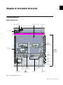
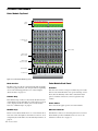
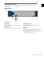
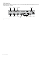


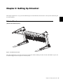
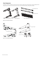
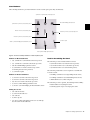
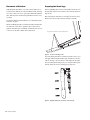
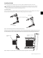
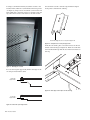
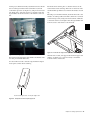
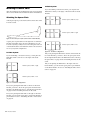
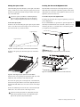
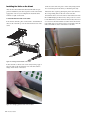
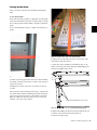
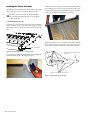
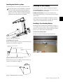
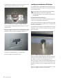
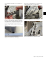
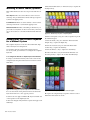
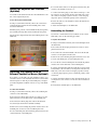

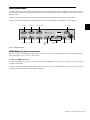
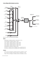

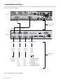

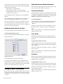

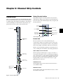
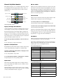
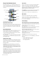
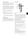
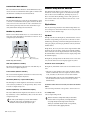
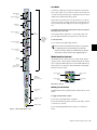
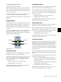

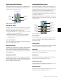
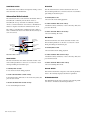
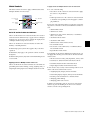
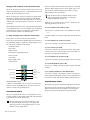
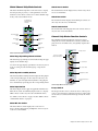
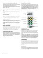
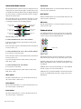

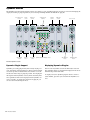

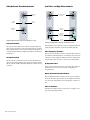
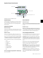

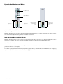
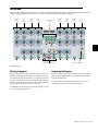
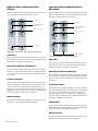
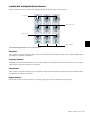

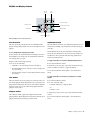
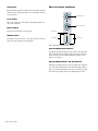
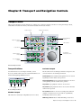
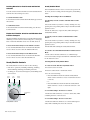

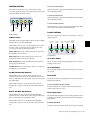
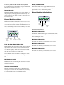
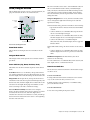

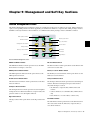
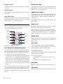
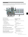
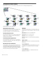

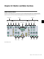
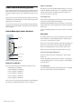
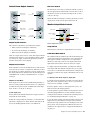
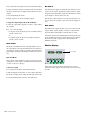
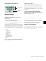
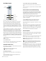
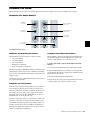
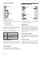

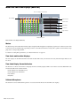
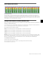


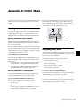

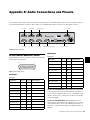
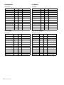
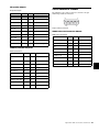


![D-Control Guide v7.3 - akmedia.[bleep]digidesign.](http://vs1.manualzilla.com/store/data/006638518_3-22bc31a56bb7c920ddb184f9348826e8-150x150.png)