1
DATA U10
CITY MULTI
SYSTEM DESIGN H2i Y SERIES
1. Electrical work.................................................................................................................................................. 4 - 86
1-1.General cautions ....................................................................................................................................... 4 - 86
1-2.Power supply for Indoor unit and Outdoor unit .......................................................................................... 4 - 87
1-3.Power cable specifications ........................................................................................................................ 4 - 89
1-4.Power supply examples............................................................................................................................. 4 - 90
2. M-NET control.................................................................................................................................................. 4 - 92
2-1.Transmission cable length limitation.......................................................................................................... 4 - 92
2-2.Transmission cable specifications ............................................................................................................. 4 - 93
2-3.System configuration restrictions............................................................................................................... 4 - 94
2-4.Address setting.......................................................................................................................................... 4 - 97
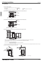
3. Piping Design................................................................................................................................................... 4 - 110
3-1.R410A Piping material............................................................................................................................... 4 - 110
3-2.Piping Design ............................................................................................................................................ 4 - 110
3-3.Refrigerant charging calculation ................................................................................................................ 4 - 112
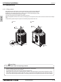
4. Outdoor Installation.......................................................................................................................................... 4 - 113
4-1.Requirement on installation site ................................................................................................................ 4 - 113
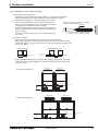
4-2.Spacing...................................................................................................................................................... 4 - 114
4-3.Piping direction .......................................................................................................................................... 4 - 116
4-4.Weather countermeasure .......................................................................................................................... 4 - 121
4-5.Caution on selecting outdoor units ............................................................................................................ 4 - 122
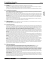
5. Installation information..................................................................................................................................... 4 - 123
5-1.General precautions .................................................................................................................................. 4 - 123
5-2.Precautions for Indoor unit ........................................................................................................................ 4 - 124
5-3.Precautions for Outdoor unit/Heat source unit .......................................................................................... 4 - 125
5-4.Precautions for Control-related items ........................................................................................................ 4 - 126
6. Caution for refrigerant leakage ........................................................................................................................ 4 - 127
6-1.Refrigerant property................................................................................................................................... 4 - 127
6-2.Confirm the Critical concentration and take countermeasure.................................................................... 4 - 127
SYSTEM DESIGN H2i Y SERIES
4 - 85
1. Electrical work
DATA U10
1-1. General cautions
1. Electrical work
I.
Follow ordinance of your governmental organization for technical standard related to electrical equipment, wiring
regulations, and guidance of each electric power company.
Wiring for control (hereinafter referred to as transmission cable) shall be (50mm[1-5/8in] or more) apart from power source
wiring so that it is not influenced by electric noise from power source wiring. (Do not insert transmission cable and power
S.D. H2i Y
source wire in the same conduit.)
Be sure to provide designated grounding work to outdoor unit.
Give some allowance to wiring for electrical part box of indoor and outdoor units, because the box is sometimes removed
at the time of service work.
Never connect 100V, 208~230V power source to terminal block of transmission cable. If connected, electrical parts will be
damaged.
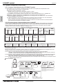
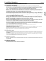
Use 2-core shield cable for transmission cable. If transmission cables of different systems are wired with the same
multiplecore cable, the resultant poor transmitting and receiving will cause erroneous operations.
When extending the transmission line, make sure to extend the shield cable as well.
Indoor unit
Outdoor
unit
OK
2-core shield cable
Indoor unit
Outdoor
unit
NO
Multiplecore cable
Remote
controller
BC controller
Remote
controller
BC controller
2-core shield cable
SYSTEM DESIGN
4 - 86
1. Electrical work
DATA U10
1-2. Power supply for Indoor unit and Outdoor unit
1-2-1. Electrical characteristics of Indoor unit
Symbols: MCA : Minimum Circuit Ampacity (=1.25xFLA) FLA : Full Load Amps
IFM :Indoor Fan Motor
Model
PMFY-P06NBMU-E
PMFY-P08NBMU-E
PMFY-P12NBMU-E
PMFY-P15NBMU-E
PEFY-P06NMAU-E3
PEFY-P08NMAU-E3
PEFY-P12NMAU-E3
PEFY-P15NMAU-E3
PEFY-P18NMAU-E3
PEFY-P24NMAU-E3
PEFY-P27NMAU-E3
PEFY-P30NMAU-E3
PEFY-P36NMAU-E3
PEFY-P48NMAU-E3
PEFY-P54NMAU-E3
PEFY-P06NMSU-E
PEFY-P08NMSU-E
PEFY-P12NMSU-E
PEFY-P15NMSU-E
PEFY-P18NMSU-E
PEFY-P24NMSU-E
PEFY-P15NMHU-E2
PEFY-P18NMHU-E2
PEFY-P24NMHU-E2
PEFY-P27NMHU-E2
PEFY-P30NMHU-E2
PEFY-P36NMHU-E2
PEFY-P48NMHU-E2
PEFY-P54NMHU-E2
PEFY-P72NMHSU-E
PEFY-P96NMHSU-E
Output(kW)
0.015 / 0.015
0.015 / 0.015
0.015 / 0.015
0.015 / 0.015
0.020 / 0.020
0.015 / 0.015
0.020 / 0.020
0.020 / 0.020
0.050 / 0.050
0.050 / 0.050
0.050 / 0.050
0.050 / 0.050
0.050 / 0.050
0.120 / 0.120
FLA(A)
0.34 / 0.37
0.34 / 0.37
0.34 / 0.37
0.38 / 0.42
0.39 / 0.43
0.23 / 0.23
0.28 / 0.28
0.28 / 0.28
0.51 / 0.51
0.51 / 0.51
0.51 / 0.51
0.51 / 0.51
0.51 / 0.51
1.00 / 1.00
198 to 253V
0.25 / 0.25
0.25 / 0.25
0.26 / 0.26
0.33 / 0.33
0.028 / 0.028
0.028 / 0.028
0.028 / 0.028
0.028 / 0.028
0.20 / 0.20
0.20 / 0.20
0.21 / 0.21
0.26 / 0.26
188 to 253V
1.05 / 1.05
1.05 / 1.05
1.20 / 1.20
1.45 / 1.45
1.56 / 1.56
2.73 / 2.73
2.73 / 2.73
2.73 / 2.73
3.32 / 3.32
3.41 / 3.41
3.31 / 3.31
0.085 / 0.085
0.085 / 0.085
0.085 / 0.085
0.085 / 0.085
0.085 / 0.085
0.121 / 0.121
0.121 / 0.121
0.121 / 0.121
0.244 / 0.244
0.244 / 0.244
0.244 / 0.244
0.84 / 0.84
0.84 / 0.84
0.96 / 0.96
1.16 / 1.16
1.25 / 1.25
2.18 / 2.18
2.18 / 2.18
2.18 / 2.18
2.66 / 2.66
2.73 / 2.73
2.65 / 2.65
0.47 / 0.50
0.47 / 0.50
0.68 / 0.74
1.20 / 1.33
1.20 / 1.33
1.57 / 1.73
1.63 / 1.50
1.63 / 1.50
2.11 / 1.83
2.35 / 2.13
2.70 / 2.45
4.16 / 3.67
4.16 / 3.67
4.18 / 3.69
7.7
8.2
0.023 / 0.023
0.023 / 0.023
0.032 / 0.032
0.130 / 0.130
0.130 / 0.130
0.180 / 0.180
0.17
0.17
0.25
0.26
0.31
0.49
0.49
0.55
0.87
0.87
0.32 / 0.31
0.41 / 0.39
0.46 / 0.43
0.47 / 0.45
0.64 / 0.60
0.88 / 0.83
1.30 / 1.20
1.30 / 1.20
1.69 / 1.46
1.88 / 1.70
2.16 / 1.96
3.32 / 2.94
3.32 / 2.94
3.34 / 2.95
6.2
6.6
208 / 230V
198 to 253V
60Hz
60Hz
208 / 230V
208 / 230V
188 to 253V
60Hz
IFM
MCA(A)
0.43 / 0.47
0.43 / 0.47
0.43 / 0.47
0.48 / 0.53
0.49 / 0.54
0.29 / 0.29
0.35 / 0.35
0.35 / 0.35
0.64 / 0.64
0.64 / 0.64
0.64 / 0.64
0.64 / 0.64
0.64 / 0.64
1.25 / 1.25
188 to 253V
60Hz
Output : Fan motor rated output
208 / 230V
187 to 253V
SYSTEM DESIGN
4 - 87
S.D. H2i Y
PLFY-P06NLMU-E
PLFY-P08NLMU-E
PLFY-P12NLMU-E
PLFY-P15NLMU-E
PLFY-P18NLMU-E
PLFY-P08NCMU-E
PLFY-P12NCMU-E
PLFY-P15NCMU-E
PLFY-P12NBMU-E
PLFY-P15NBMU-E
PLFY-P18NBMU-E
PLFY-P24NBMU-E
PLFY-P30NBMU-E
PLFY-P36NBMU-E
Hz
Indoor Unit
Volts
Voltage range
1. Electrical work
DATA U10
Symbols: MCA : Minimum Circuit Ampacity (=1.25xFLA) FLA : Full Load Amps
IFM :Indoor Fan Motor
Model
S.D. H2i Y
PCFY-P15NKMU-E
PCFY-P24NKMU-E
PCFY-P30NKMU-E
PCFY-P36NKMU-E
PKFY-P06NBMU-E2
PKFY-P08NHMU-E2
PKFY-P12NHMU-E2
PKFY-P15NHMU-E2
PKFY-P18NHMU-E2
PKFY-P24NKMU-E2
PKFY-P30NKMU-E2
PFFY-P06NEMU-E
PFFY-P08NEMU-E
PFFY-P12NEMU-E
PFFY-P15NEMU-E
PFFY-P18NEMU-E
PFFY-P24NEMU-E
PFFY-P06NRMU-E
PFFY-P08NRMU-E
PFFY-P12NRMU-E
PFFY-P15NRMU-E
PFFY-P18NRMU-E
PFFY-P24NRMU-E
Hz
60Hz
60Hz
60Hz
60Hz
Indoor Unit
Volts
Voltage range
208 / 230V
208 / 230V
208 / 230V
208 / 230V
Output : Fan motor rated output
IFM
MCA(A)
0.44 / 0.44
0.52 / 0.52
1.22 / 1.22
1.22 / 1.22
Output(kW)
0.090 / 0.090
0.095 / 0.095
0.160 / 0.160
0.160 / 0.160
FLA(A)
0.35 / 0.35
0.41 / 0.41
0.97 / 0.97
0.97 / 0.97
198 to 253V
0.19 / 0.19
0.38 / 0.38
0.38 / 0.38
0.38 / 0.38
0.38 / 0.38
0.63 / 0.63
0.63 / 0.63
0.008 / 0.008
0.030 / 0.030
0.030 / 0.030
0.030 / 0.030
0.030 / 0.030
0.056 / 0.056
0.056 / 0.056
0.15 / 0.15
0.30 / 0.30
0.30 / 0.30
0.30 / 0.30
0.30 / 0.30
0.50 / 0.50
0.50 / 0.50
188 to 253V
0.32 / 0.34
0.32 / 0.34
0.34 / 0.38
0.40 / 0.44
0.48 / 0.53
0.59 / 0.64
0.015 / 0.015
0.015 / 0.015
0.018 / 0.018
0.030 / 0.030
0.035 / 0.035
0.063 / 0.063
0.25 / 0.27
0.25 / 0.27
0.27 / 0.30
0.32 / 0.35
0.38 / 0.42
0.47 / 0.51
188 to 253V
0.32 / 0.34
0.32 / 0.34
0.34 / 0.38
0.40 / 0.44
0.48 / 0.53
0.59 / 0.64
0.015 / 0.015
0.015 / 0.015
0.018 / 0.018
0.030 / 0.030
0.035 / 0.035
0.063 / 0.063
0.25 / 0.27
0.25 / 0.27
0.27 / 0.30
0.32 / 0.35
0.38 / 0.42
0.47 / 0.51
198 to 253V
SYSTEM DESIGN
4 - 88
1. Electrical work
DATA U10
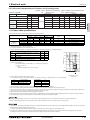
1-2-2. Electrical characteristics of Outdoor unit of cooling mode
Symbols: MCA : Minimum Circuit Ampacity
SC : Starting Current
PUHY-HP-T(S)JMU
Compressor
Outdoor Units
Unit Combination
Model
MOCP : Maximum Overcurrent Protection
RLA : Rated Load Amps
Hz
Volts
Voltage range
RLA(A)
RLA(MAX)(A)
MCA(A)
MOCP
Fan
Output(kW) SC(A) Output(kW)
60Hz 208 / 230V
19.4 / 17.6
38.4 / 38.4
59 / 54
101 / 92
5.3
15
0.92
PUHY-HP96TJMU-A
60Hz 208 / 230V
28.2 / 25.5
52.4 / 52.4
74 / 68 127 / 116
6.7
15
0.92
PUHY-HP
144TSJMU-A PUHY-HP72TJMU-A
60Hz 208 / 230V
19.4 / 17.6
38.4 / 38.4
59 / 54
101 / 92
5.3
15
0.92
60Hz 208 / 230V
19.4 / 17.6
38.4 / 38.4
59 / 54
101 / 92
5.3
15
0.92
PUHY-HP96TJMU-A
PUHY-HP
192TSJMU-A PUHY-HP96TJMU-A
60Hz 208 / 230V
28.2 / 25.5
52.4 / 52.4
74 / 68 127 / 116
6.7
15
0.92
60Hz 208 / 230V
28.2 / 25.5
52.4 / 52.4
74 / 68 127 / 116
6.7
15
0.92
PUHY-HP72TJMU-A
188 to 253V
1-3. Power cable specifications
Thickness of wire for main power supply, capacities of the switch and system impedance
3-phase 3-wire, 208V, 60Hz
Swith (A)
Breaker for wiring
(NFB)
Breaker for current leakage
60
60
60A 100mA 0.1sec. or less
75
75
75A 100mA 0.1sec. or less
15
15
15
15A current sensitivity *2
3.3/12
20
20
20
20A current sensitivity *2
5.3/10
30
30
30
30A current sensitivity *2
Main cable
Branch
Ground
Capacity
Fuse
HP72
13.3/6
-
13.3/6
60
HP96
21.2/4
-
21.2/4
75
F0 = 15 or less *1
2.1/14
2.1/14
2.1/14
F0 = 20 or less *1
3.3/12
3.3/12
F0 = 30 or less *1
5.3/10
5.3/10
PUHY-HP-TJMU
Total operating
current of
the indoor unit
Minimum wire thickness (mm2/AWG)
*1 Please take the larger of F1 or F2 as the value for F0.
F1 = Total operating maximum curent of the indoor units × 1.2
F2 = {V1 × (Quantity of Type1)/C} + {V1 × (Quantity of Type2)/C} + {V1 × (Quantity of Type3)/C} + {V1 × (Quantity of Others)/C}
PLFY-NBMU, PMFY-NBMU, PEFY-NMSU, PCFY-NKMU,
PKFY-NHMU, PKFY-NKMU
Type2
PEFY-NMAU
Type3
PEFY-NMHSU
Others
V1
V2
18.6
2.4
38
1.6
13.8
4.8
0
0
Other indoor unit
C : Multiple of tripping current at tripping time 0.01s
Please pick up "C" from the tripping characteristic of the breaker.
<Example of "F2" calculation>
*Condition PEFY-NMSU × 4 + PEFY-NMAU × 1, C = 8 (refer to right sample chart)
6000
600
Tripping Time [s]
Indoor unit
Type1
SAMPLE
60
10
1
F2 = 18.6 × 4/8 + 38 × 1/8
= 14.05
0.1
16 A breaker (Tripping current = 8 × 16 A at 0.01s)
0.01
1
2
3 4
6 8 10
20
C
Rated Tripping current (x)
Sample chart
*2 Current sensitivity is calculated using the following formula.
G1 = (V2 × Quantity of Type1) + (V2 × Quantity of Type2) + (V2 × Quantity of Type3) + (V2 × Quantity of Others) + (V3 × Wire length [km])
Wire thickness
V3
30 or less
G1
30 mA 0.1sec or less
Current sensitivity
1.5 mm2
48
100 or less
100 mA 0.1sec or less
2.5 mm2
56
4.0 mm2
66
1. Use dedicated power supplies for the outdoor unit and indoor unit. Ensure OC and OS are wired individually.
2. Bear in mind ambient conditions (ambient temperature,direct sunlight, rain water,etc.) when proceeding with the wiring and connections.
3. The wire size is the minimum value f or metal conduit wiring. The power cord size should be 1 rank thicker consideration of voltage drops. Make sure the power-supply voltage does not
drop more than 10 %. Make sure that the voltage imbalance between the phases is 2% or less.
4. Specific wiring requirements should adhere to the wiring regulations of the region.
5. Power supply cords o f parts of appliances for outdoor use shall not be lighter than polychloroprene sheathed flexible cord (design 245 IEC57). For example, use wiring such as YZW.
6. A switch with at least 3 mm [1/8 in] contact separation in each pole shall be provided by the Air conditioner installation.
Be sure to use specified wires to connect so that no external force is imparted to terminal connections. If connections are not fixed firmly, it may cause heating or fire.
Be sure to use the appropriate type of overcurrent protection switch. Note that generated overcurrent may include some amount of direct current.
The breakers for current leakage should support Inverter circuit. (e.g. Mitsubishi Electric's NV-C series or equivalent). If no earth leakage breaker is installed, it may cause an electric shock.
Breakers for current leakage should combine using of switch.
Do not use anything other than a breaker with the correct capacity. Using a breaker of too large capacity may cause malfunction or fire.
If a large electric current flows due to malfunction or faulty wiring, earth-leakage breakers on the unit side and on the upstream side of the power supply system may both operate.
Depending on the importance of the system, separate the power supply system or take protective coordination of breakers.
SYSTEM DESIGN
4 - 89
S.D. H2i Y
PUHY-HP72TJMU-A
1. Electrical work
DATA U10
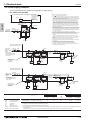
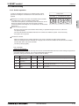
1-4. Power supply examples
The local standards and/or regulations is applicable at a higher priority.
1-4-1. PUHY-HP72, 96TJMU
Note:
1 The transmission cable is not-polarity double-wire.
2 Symbol
means a screw terminal for wiring.
3 The shield wire of transmission cable should be connected to the grounding terminal at
Outdoor unit. All shield wire of M-Net transmission cable among Indoor units should be
connected to the S terminal at Indoor unit or all shield wire should be connected together.
The broken line at the scheme means shield wire.
4 When the Outdoor unit connected with system controller, power-supply to TB7 of the
outdoor unit(s) is needed. The connector change from CN41 to CN40 at one of the
outdoor units will enable the outdoor unit to supply power to TB7, or an extra power
supply unit PAC-SC50KUA should be used. The transmission cable (above 1.25mm2,
shielded, CVVS/CPEVS/MVVS) among Outdoor units and system controllers is called
central control transmission cable. The shield wire of the central control transmission
cable must be grounded at the Outdoor unit whose CN41 is changed to CN40. When the
power supply unit PAC-SC51KUA is used, connect the shielded cable to the ground
terminal on the PAC-SC51KUA.
5 MA R/C transmission cable (0.3-1.25mm2) must be less than 200m in length, while ME
R/C transmission cable (0.3-1.25mm2) must be less than 10m in length. But transmission
cable to the ME R/C can be extend using a M-NET cable (>=1.25mm2) when the length
is counted in the M-Net length. Both Compact MA and ME R/C transmission cables size
0.75~1.25mm2 in thickness.
6 To wire PAC-YT53CRAU, use a wire with a diameter of 0.3mm2 [AWG 22].
7 MA remote controller and ME remote controller should not be grouped together.
8 If using 1 or 2 (main/sub) MA remote controller to control more than 1 Indoor unit, use MA
transmission cable to connect all the TB15 terminals of the Indoor units. It is called
"Grouping".
If using 1 or 2 (main/sub) ME remote controller control more than 1 indoor unit, set
address to Indoor unit and ME remote controller. For the method, refer to 2-4. "Address
setting".
9 Indoor board consumes power from TB3. The power balance should be considered
according to System Design 2-3 "System configuration restrictions".
10 If Transmission booster is needed, be sure to connect the shield wires to the both sides
to the booster.
11 The critical current for choosing power source equipment is approximate
1.4 times of total rated current of the Outdoor unit(s) or Indoor unit(s).
12 When System controller (SC) is connected to the system, turn the SW2-1 on.
13 The phases of electricity power must be confirmed to be right used. Phase-reverse, or
phase-missing could break the controllers.
<In the case a system controller is connected.>
S.D. H2i Y
Note12
Central control
transmission cable
>=1.25mm2
Shield cable
(CVVS, CPEVS
MVVS)
SC
Connector
CN41 CN40 OU
Note4
Note4
To other OU
Breakers for
current leakage Switch
Power supply
3-phase 3-wire
208-230V 60Hz
Note11,13
TB1
TB3 TB7
(L1,L2,L3) (M1,M2) (M1,M2)
TB7
(S)
G
Note3
To *1 or *2
*1
(Using MA remote controller)
Connecting TB5 terminal.
Breakers for
Pull box
Power supply current leakage Switch
1-phase
208-230V 60Hz
Note11
Note8
TB5 TB2 TB15
(M1,M2) (L,N) (1,2)
S
(Shield)
IU
* Power supply
specifications vary with
the model of connected
indoor units
TB5 TB2 TB15
(M1,M2) (L,N) (1,2)
S
(Shield)
Breakers for
Power supply current leakage Switch
1-phase
208-230V 60Hz
TB1
(L1,L2) E
TB2 TB3
TB5 TB2 TB15
(M1,M2) (L,N) (1,2)
S
(Shield)
S
(Shield)
Indoor-outdoor
transmission cable
>=1.25mm2
Shield cable
(Shield)
MA R/C cable
0.3-1.25mm2
<=200m
Note5
Transmission
booster
Note9
Note10
Note7
Note8
MA R/C
S
TB5 TB2 TB15
(M1,M2) (L,N) (1,2)
S
(Shield)
G
MA R/C
MA R/C
*2
(Using ME remote controller)
Connecting TB5 terminal.
Breakers for
Pull box
Power supply current leakage Switch
1-phase
208-230V 60Hz
Note11
Note8
TB5 TB2 TB15
(M1,M2) (L,N) (1,2)
S
(Shield)
IU
* Power supply
specifications vary with
the model of connected
indoor units
TB5 TB2 TB15
(M1,M2) (L,N) (1,2)
S
(Shield)
Breakers for
Power supply current leakage Switch
1-phase
208-230V 60Hz
TB5 TB2 TB15
(M1,M2) (L,N) (1,2)
S
(Shield)
TB1
(L1,L2) E
TB2 TB3
(Shield)
Indoor-outdoor
transmission cable
>=1.25mm2
Shield cable
ME R/C
Symbol
Model
BKC
OCP
NFB
OU
IU
SC
Breaker capacity
Over-current protector
Non-fuse breaker
Outdoor unit
Indoor unit
System controller
MA R/C
MA remote controller
ME R/C
ME remote controller
PUHY-HP72TJMU
PUHY-HP96TJMU
*1
*2
*3
*4
60A 100mA 0.1sec. or less
75A 100mA 0.1sec. or less
S
ME R/C cable
0.3~1.25mm2
<=10m
Note5
(Shield)
Transmission
booster
Note9
Note10
Note7
Note8
ME R/C
Breakers for current leakage
*1, *2, *4
S
TB5 TB2 TB15
(M1,M2) (L,N) (1,2)
S
(Shield)
G
ME R/C
Switch
Switch*4
BKC
<A>
OCP*3, *4
<A>
(NFB)
<A>
60
75
60
75
60
75
Minimum Wire thickness
Power wire
<mm2/AWG>
13.3/6
21.4/4
PE wire
<mm2/AWG>
13.3/6
21.4/4
The breakers for current leakage should support Inverter circuit. (e.g. Mitsubishi Electric's NV-C series or equivalent).
Breakers for current leakage should combine using of switch.
It shows data for B-type fuse of the breaker for current leakage.
If a large electric current flows due to malfunction or faulty wiring, earth-leakage breakers on the unit side and on the centralized controller side
may both operate.
Depending on the importance of the system, separate the power supply system or take protective coordination of breakers.
SYSTEM DESIGN
4 - 90
1. Electrical work
DATA U10
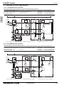
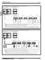
The local standards and/or regulations is applicable at a higher priority.
1-4-2. PUHY-HP144, 192TSJMU
<In the case a system controller is connected.>
Note12
Central control
transmission cable
>=1.25mm2
Shield cable
(CVVS, CPEVS
MVVS)
SC
Connector
CN41 CN40 OU
Note4
Note4
OU
To other OU
TB1
TB3 TB7
(L1,L2,L3) (M1,M2) (M1,M2)
Breakers for
TB7
(S)
TB1
(L1,L2,L3)
TB3
TB7
(M1,M2) (M1,M2)
Power supply current leakage Switch
3-phase 3-wire
208-230V 60Hz
Note11,13
G
G
Note3
Note3
To *1 or *2
*1
(Using MA remote controller)
Connecting TB5 terminal.
Breakers for
current leakage Switch
Pull box
Power supply
1-phase
208-230V 60Hz
Note11
Note8
TB5 TB2 TB15
(M1,M2) (L,N) (1,2)
S
(Shield)
IU
* Power supply
specifications vary with
the model of connected
indoor units
TB5 TB2 TB15
(M1,M2) (L,N) (1,2)
S
(Shield)
Breakers for
Power supply current leakage Switch
1-phase
208-230V 60Hz
TB5 TB2 TB15
(M1,M2) (L,N) (1,2)
S
(Shield)
TB1
(L1,L2) E
TB2 TB3
S
(Shield)
Indoor-outdoor
transmission cable
>=1.25mm2
Shield cable
MA R/C cable
0.3-1.25mm2
<=200m
Note5
(Shield)
Transmission
booster
Note9
Note10
Note7
Note8
MA R/C
S
TB5 TB2 TB15
(M1,M2) (L,N) (1,2)
S
(Shield)
G
MA R/C
MA R/C
*2
(Using ME remote controller)
Connecting TB5 terminal.
Breakers for
current leakage Switch
Pull box
Power supply
1-phase
208-230V 60Hz
Note11
Note8
TB5 TB2 TB15
(M1,M2) (L,N) (1,2)
S
(Shield)
IU
* Power supply
specifications vary with
the model of connected
indoor units
TB5 TB2 TB15
(M1,M2) (L,N) (1,2)
S
(Shield)
TB5 TB2 TB15
(M1,M2) (L,N) (1,2)
S
(Shield)
Breakers for
Switch
Power supply current leakage
1-phase
208-230V 60Hz
TB1
(L1,L2) E
TB2 TB3
(Shield)
Indoor-outdoor
transmission cable
>=1.25mm2
Shield cable
ME R/C
Symbol
Model
BKC
OCP
Breaker capacity
Over-current protector
NFB
OU
IU
SC
Non-fuse breaker
Outdoor unit
Indoor unit
System controller
MA R/C
MA remote controller
ME R/C
ME remote controller
PUHY-HP72TJMU
PUHY-HP96TJMU
*1
*2
*3
*4
60A 100mA 0.1sec. or less
75A 100mA 0.1sec. or less
S
ME R/C cable
0.3~1.25mm2
<=10m
Note5
(Shield)
Transmission
booster
Note9
Note10
Note7
Note8
ME R/C
Breakers for current leakage
*1, *2, *4
S
TB5 TB2 TB15
(M1,M2) (L,N) (1,2)
S
(Shield)
G
ME R/C
Switch
Switch*4
BKC
<A>
OCP*3, *4
<A>
(NFB)
<A>
60
75
60
75
60
75
Minimum Wire thickness
Power wire
<mm2/AWG>
13.3/6
21.4/4
PE wire
<mm2/AWG>
13.3/6
21.4/4
The breakers for current leakage should support Inverter circuit. (e.g. Mitsubishi Electric's NV-C series or equivalent).
Breakers for current leakage should combine using of switch.
It shows data for B-type fuse of the breaker for current leakage.
If a large electric current flows due to malfunction or faulty wiring, earth-leakage breakers on the unit side and on the centralized controller side
may both operate.
Depending on the importance of the system, separate the power supply system or take protective coordination of breakers.
SYSTEM DESIGN
4 - 91
S.D. H2i Y
Breakers for
Power supply current leakage Switch
3-phase 3-wire
208-230V 60Hz
Note11,13
Note:
1 The transmission cable is not-polarity double-wire.
2 Symbol
means a screw terminal for wiring.
3 The shield wire of transmission cable should be connected to the grounding terminal at
Outdoor unit. All shield wire of M-Net transmission cable among Indoor units should be
connected to the S terminal at Indoor unit or all shield wire should be connected together.
The broken line at the scheme means shield wire.
4 When the Outdoor unit connected with system controller, power-supply to TB7 of the
outdoor unit(s) is needed. The connector change from CN41 to CN40 at one of the
outdoor units will enable the outdoor unit to supply power to TB7, or an extra power
supply unit PAC-SC50KUA should be used. The transmission cable (above 1.25mm2,
shielded, CVVS/CPEVS/MVVS) among Outdoor units and system controllers is called
central control transmission cable. The shield wire of the central control transmission
cable must be grounded at the Outdoor unit whose CN41 is changed to CN40. When the
power supply unit PAC-SC51KUA is used, connect the shielded cable to the ground
terminal on the PAC-SC51KUA.
5 MA R/C transmission cable (0.3-1.25mm2) must be less than 200m in length, while ME
R/C transmission cable (0.3-1.25mm2) must be less than 10m in length. But transmission
TB7 cable to the ME R/C can be extend using a M-NET cable (>=1.25mm2) when the length
(S) is counted in the M-Net length. Both Compact MA and ME R/C transmission cables size
0.75~1.25mm2 in thickness.
6 To wire PAC-YT53CRAU, use a wire with a diameter of 0.3mm2 [AWG 22].
7 MA remote controller and ME remote controller should not be grouped together.
8 If using 1 or 2 (main/sub) MA remote controller to control more than 1 Indoor unit, use MA
transmission cable to connect all the TB15 terminals of the Indoor units. It is called
"Grouping".
If using 1 or 2 (main/sub) ME remote controller control more than 1 indoor unit, set
address to Indoor unit and ME remote controller. For the method, refer to 2-4. "Address
setting".
9 Indoor board consumes power from TB3. The power balance should be considered
according to System Design 2-3 "System configuration restrictions".
10 If Transmission booster is needed, be sure to connect the shield wires to the both sides
to the booster.
11 The critical current for choosing power source equipment is approximate
1.4 times of total rated current of the Outdoor unit(s) or Indoor unit(s).
12 When System controller (SC) is connected to the system, turn the SW2-1 on.
13 The phases of electricity power must be confirmed to be right used. Phase-reverse, or
phase-missing could break the controllers.
2. M-NET control
DATA U10
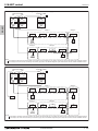
2-1. Transmission cable length limitation
2. M-NET control
2-1-1. Using MA Remote controller
MA remote controller refers to Simple MA remote controller and wireless remote controller.
Long transmission cable causes voltage down, therefore, the length limitation should be obeyed to secure proper transmission.
Max. length via Outdoor (M-NET cable) L1+L2+L3+L4, L1+L2+L6+L7, L3+L4+L6+L7 <=500m[1640ft.] 1.25mm2 [AWG16] or thicker
Max. length to Outdoor (M-NET cable) L1+L8, L3+L4, L6, L2+L6+L8, L7
<=200m[656ft.] 1.25mm2 [AWG16] or thicker
Max. length from MA to Indoor
a1+a2, a1+a2+a3+a4
<=200m[656ft.] 0.3-1.25 mm2 [AWG22-16]
24VDC to AG-150A-A
n
<=50m[164ft.]
0.75-2.0 mm2 [AWG18-14]
L1
Group1
Group3
Group5
OS
OC
IC
IC
IC
IC
(52)
(51)
(01)
(04)
(05)
(06)
TB3
M1M2
TB3
M1M2
TB5
M1M2 S
TB15
1 2
TB5
M1M2 S
TB15
1 2
TB5
M1M2 S
TB15
1 2
TB5
M1M2 S
TB15
1 2
a2
TB7
M1M2 S
L2
MA
L4
IC
(54 )
TB7
IC
(03)
(02)
TB3
M1M2
TB5
M1M2 S
IC
(07)
TB5 TB 15
M1M2 S 1 2
TB15
1 2
TB15
1 2
TB5
M1M2 S
V+V-FG
AG-150A-A
A B S
A B
A B
MA
MA
n
L7
A B S
a1
Power Supply Unit
PAC-SC51KUA
a4
L6
M1 M2 S
MA
L3
OC
a3
A B
a2
A B
Shielded wire
a2
a1
a1
TB7
M1M2 S
V+V-FG
NOTE
Do not daisy-chain remote controllers.
OC, OS : Outdoor unit controller; IC: Indoor unit controller; MA: MA remote controller
2-1-2. Using ME Remote controller
ME remote controller refers to Smart ME Controller.
Long transmission cable causes voltage down, therefore, the length limitation should be obeyed to secure proper transmission.
Max. length via Outdoor (M-NET cable) L1+L2+L3+L4, L1+L2+L6+L7,L1+L2+L3+L5, L3+L4+L6+L7 <=500m[1640ft.] 1.25mm2 [AWG16] or thicker
Max. length to Outdoor (M-NET cable) L1+L8, L3+L4, L6, L2+L6+L8, L7, L3+L5
<=200m[656ft.] 1.25mm2 [AWG16] or thicker
Max. length from ME to Indoor
e1, e2+e3, e4
<=10m[32ft.]*1
0.3-1.25 mm2 [AWG22-16] *1
24VDC to AG-150A-A
n
<=50m[164ft.]
0.75-2.0 mm2 [AWG18-14]
*1. If the length from ME to Indoor exceed 10m, use 1.25 mm2 [AWG16] shielded cable, but the total length should be counted into Max. length via Outdoor.
L1
L8
Group1
Group3
Group5
OS
OC
IC
IC
IC
IC
(52)
(51)
(01)
(04)
(05)
(06)
TB3
M1M2
TB3
M1M2
TB7
M1M2 S
TB7
M1M2 S
TB5
M1M2 S
e2
A B
A B
A B
(101)
(105)
(155)
ME
ME
L2
ME
L3
OC
L4
(54 )
TB7
TB3
M1M2
IC
IC
(02)
(03)
TB5
M1M2 S
TB5
M1M2 S
IC
(07)
TB5
M1M2 S
L6
L5
M1 M2 S
TB5
M1M2 S
e3
TB5
M1M2 S
e1
TB5
M1M2 S
Shielded wire
A B S
e4
Power Supply Unit
PAC-SC51KUA
V+V-FG
A B
n
(103)
L7
S.D. H2i Y
L8
AG-150A-A
A B S
ME
V+V-FG
OC, OS : Outdoor unit controller; IC: Indoor unit controller; ME: ME remote controller
SYSTEM DESIGN
NOTE
Do not daisy-chain remote controllers.
4 - 92
2. M-NET control
DATA U10
2-2. Transmission cable specifications
Transmission cables (Li)
Type of cable
Cable size
Remarks
ME Remote controller cables
Shielding wire (2-core)
CVVS, CPEVS or MVVS
More than 1.25
[AWG16]
0.3 1.25
2
[AWG22 16]*2
When 10m [32ft] is exceeded, use cables with
the same specification as transmission cables.
—
MA Remote controller cables
Sheathed 2-core cable (unshielded)
CVV
mm2
SYSTEM DESIGN
2
[AWG22 16] *1 *2
Max length : 200m [656ft]
CVVS, MVVS: PVC insulated PVC jacketed shielded control cable
CPEVS: PE insulated PVC jacketed shielded communication cable
CVV: PV insulated PVC sheathed control cable
4 - 93
S.D. H2i Y
*1 To wire PAC-YT53CRAU, use a wire with a diameter of 0.3
[AWG22]
*2 The use of cables 0.75 mm2 [AWG18] or greater is recommended for easy
handling.
0.3 1.25
2. M-NET control
DATA U10
2-3. System configuration restrictions
S.D. H2i Y
2-3-1. Common restrictions for the CITY MULTI system
For each Outdoor unit, the maximum connectable quantity of Indoor unit is specified at its Specifications table.
A) 1 Group of Indoor units can have 1-16 Indoor units;
B) Maximum 2 remote controllers for 1 Group;
*MA/ME remote controllers cannot be present together in 1group.
*To wire PAC-YT53CRAU, use a wire with a diameter of 0.3 mm2 [AWG22]
C) 1 LOSSNAY unit can interlock maximum 16 Indoor units; 1 Indoor unit can interlock only 1 LOSSNAY unit.
D) Maximum 3 System controllers are connectable when connecting to TB3 of the Outdoor unit.
E) Maximum 6 System controllers are connectable when connecting to TB7 of the Outdoor unit, if the transmission
power is supplied by the Outdoor unit.
F) 4 System controllers or more are connectable when connecting to TB7 of the Outdoor unit, if the transmission
power is supplied by the power supply unit PAC-SC51KUA. Details refer to 2-3-3-C.
*System controller connected as described in D) and E) would have a risk that the failure of connected Outdoor
unit would stop power supply to the System controller.
2-3-2. Ensuring proper communication power for M-NET
In order to ensure proper communication among Outdoor unit, Indoor unit, LOSSNAY and Controllers, the transmission
power situation for the M-NET should be observed. In some cases, Transmission booster should be used. Taking the
power consumption index of Indoor unit sized P06-P54 as 1, the equivalent power consumption index and supply
capability index of others are listed at Table 2-3-1 and Table 2-3-2.
Table 2-3-1 The equivalent power consumption
BC
Indoor unit
PWFY
LOSSNAY controller
CMB
Sized
PEFY-AF1200 LGH-RX-E
P36NMU-E-BU P36NMU-E-AU P72NMU-E-AU
Sized
P06-P54 P72, 96 CFMR
1
7
2
0
2
6
1
MA RC.
PAC-YT53CRAU
PAR-FA32MA
PZ-41SLB
PZ-60DR-E
5
ME Remote controller/Adapter
PZ-52SF
PAC-YG60MCA
PAC-YG66DCA
PAC-YG63MCA
0
PAR-U01MEDU
PAC-IF01AHC-J
1/4
1/2
Centralized
ON/OFF
M-NET
Outdoor unit
MN Converter
controller
Remote controller
Interface/Converter
AG-150A-A TC-24B GB-24A LMAP04U-E PAC-YT40ANRA CMS-MNF-B CMS-MNG-E MAC-333
TB7 power consumption
EB-50GU-A
BAC-HD150
PAC-SF83MA-E
1/2
4
3
0
1
*RC: Remote Controller
1/2
0
2
0
Table 2-3-2 The equivalent power supply
Transmission Booster
Power supply unit
Expansion controller
BM ADAPTER
System Controller
Outdoor unit
Outdoor unit
PAC-SF46EPA
25
PAC-SC51KUA
5
PAC-YG50ECA
6
BAC-HD150
6
GB-50ADA-A
6
Connector TB3 and TB7 total *
32
Connector TB7 only
6
*If PAC-SC51KUA is used to supply power at TB7 side, no power supply need from Outdoor unit at TB7, Connector TB3 itself will therefore have 32.
Not applicable to the PUMY model.
With the equivalent power consumption values in Table 2-3-1 and Table 2-3-2, PAC-SF46EPA can be designed into the airconditioner system to ensure proper system communication according to 2-3-2-A, B, C.
2-3-2-A) Firstly, count from TB3 at TB3 side the total quantity of Indoor units, ME remote controller, and System
controllers. If the total quantity reaches 40, a PAC-SF46EPA should be set.In this case, Indoor units sized P72 and 96 are
counted as 2 indoor units, but MA remote controller(s) and PZ-41SLB are NOT counted.
2-3-2-B) Secondly, count from TB7 side to TB3 side the total transmission power consumption index. If the total power consumption
reaches 32, a PAC-SF46EPA should be set. Yet, if a PAC-SC51KUA or another controller with a built-in power supply,
such as PAC-YG50ECA, is used to supply power at TB7 side, count from index TB3 side only.
2-3-2-C) Thirdly, count from TB7 at TB7 side the total transmission power consumption index, If the total power consumption reaches
6, a PAC-SF46EPA should be set.
System example
TB7
TB3
UP
TRANSMISSION BOOSTER
MODEL
PAC-SF46EPA
POWER RATING
220-240V:0.7A ~/N
50
WEIGHT
3.4kg
MADE IN JAPAN
01
Transmission
booster
(No.1)
02
ME remote
controller
ME remote
controller
TB7
TB3
Outdoor unit
N1
N2
Within N2, conditions 1,2 should be followed.
1.The total quantity of Indoor units and ME remote controller
should not exceed 40.
*Indoor units sized P72 and 96 are counted as 2 units.
2.The total equivalent transmission power consumption
should not exceed 25.
Transmission booster (No.1) should be used,
if the total quantity of Indoor units and ME remote controllers
reaches 40, (Indoor units sized P72 and 96 are counted as 2);
or if the total equivalent transmission power consumption reaches 32.
UP
TRANSMISSION BOOSTER
MODEL
PAC-SF46EPA
POWER RATING
220-240V:0.7A ~/N
50
WEIGHT
3.4kg
MADE IN JAPAN
M-NET
24VDC
Power supply unit
PAC-SC51KUA
Transmission
booster
PAC-SF46EPA
(No.2)
LOSSNAY
unit
CENTRALIZED CONTROLLER AG-150A
Centralized controller
(AG-150A-A)
LOSSNAY
unit
LOSSNAY
remote controller
LOSSNAY
remote controller
N4
N3
Transmission booster (No.2) should be used,
if the total equivalent transmission power consumption reaches 5.
Within N4, the total equivalent transmission
power consumption should not exceed 25.
SYSTEM DESIGN
4 - 94
2. M-NET control
DATA U10
2-3-3. Ensuring proper power supply to System controller
The power to System controller (excluding LM-AP) is supplied via M-NET transmission line. M-NET transmission line at
TB7 side is called Central control transmission line while one at TB3 side is called Indoor-Outdoor transmission line.
There are 3 ways to supply power to the System controller .
A) Connecting to TB3 of the Outdoor unit and receiving power from the Outdoor unit.
B) Connecting to TB7 of the Outdoor unit and receiving power from the Outdoor unit.
C) Connecting to TB7 of the Outdoor unit but receiving power from power supply unit PAC-SC51KUA.
2-3-3-A. When connecting to TB3 of the Outdoor unit and receiving power from the Outdoor unit.
Fig. 2-3-3-A
M-NET transmission lines
(Indoor-Outdoor transmission lines)
Outdoor unit
Group
System controller
(excluding LM-AP)
Group
TB3
TB7
Replacement of
CN41 with CN40
Indoor unit
M-NET transmission lines
(transmission lines
for central controller)
MA remote controller
Outdoor unit
Group
Group
TB3
TB7
Use CN41
as it is.
Indoor unit
ME remote controller
System
controller
Maximum 3 System controllers can be connected to TB3.
2-3-3-B. When connecting to TB7 of the Outdoor unit and receiving power from the Outdoor unit.
Maximum 6 System controllers can be connected to TB7
and receiving power from the Outdoor unit.
It is necessary to replace power supply switch connector
CN41 with CN40 on one Outdoor unit.
Fig. 2-3-3-B
M-NET transmission lines
(Indoor-Outdoor transmission lines)
Outdoor unit
Group
Group
TB3
TB7
Replacement of
CN41 with CN40
M-NET transmission lines
(transmission lines
for central controller)
Indoor unit
MA remote controller
Outdoor unit
Group
Group
TB3
TB7
Use CN41
as it is.
Indoor unit
ME remote controller
System
controller
Maximum 6 System controllers can be connected to TB7.
2-3-3-C. When connecting to TB7 of the Outdoor unit but receiving power from PAC-SC51KUA.
When using PAC-SC51KUA to supply transmission power,
Fig. 2-3-3-C
M-NET transmission lines
the power supply connector CN41 on the Outdoor units
(Indoor-Outdoor transmission lines)
Outdoor unit
should be kept as it is. It is also a factory setting.
Group
TB3
1 PAC-SC51KUA supports maximum 1 AG-150A-A or 1
TB7
Use CN41
EB-50GU-A unit due to the limited power 24VDC at its TB3.
as it is.
However, 1 PAC-SC51KUA supplies transmission power at
M-NET transmission lines
(transmission lines
MA remote controller
for central controller)
its TB2 equal to 5 Indoor units, which is referable at Table
2-3-2.
Outdoor unit
Group
If PZ-52SF, System controller, ON/OFF controller connected
TB3
TB7
to TB7 consume transmission power more than 5 (Indoor
Use CN41
as it is.
units), Transmission booster PAC-SF46EPA is needed.
PAC-SF46EPA supplies transmission power equal to 25
PAC-SC51KUA
ME remote controller
Indoor units.
CAUTION
Group
Indoor unit
Group
Indoor unit
System
controller
AG-150A-A/EB-50GU-A*1 are recommended to connect to TB7 because it performs back-up to a number of data.
In an air conditioner system has more than 1 Outdoor units, AG-150A-A/EB-50GU-A receiving transmission power through TB3 or TB7 on one of the Outdoor
units would have a risk that the connected Outdoor unit failure would stop power supply to AG-150A-A/EB-50GU-A and disrupt the whole system.
When applying apportioned electric power function, AG-150A-A/EB-50GU-A are necessary to connected to TB7 and has its own power supply unit
PAC-SC51KUA.
Note: Power supply unit PAC-SC51KUA is for AG-150A-A/EB-50GU-A.
*1: AG-150A-A is an example model of system controllers.
SYSTEM DESIGN
4 - 95
S.D. H2i Y
Maximum 3 System controllers can be connected to TB3.
If there is more than 1 Outdoor unit, it is necessary to
replace power supply switch connector CN41 with CN40
on one Outdoor unit.
2. M-NET control
DATA U10
2-3-4. Power supply to LM-AP
1-phase 208-230V AC power supply is needed.
The power supply unit PAC-SC51KUA is not necessary when connecting only the LM-AP. Yet, make sure to change
the power supply changeover connector CN41 to CN40 on the LM-AP.
2-3-5. Power supply to expansion controller
S.D. H2i Y
1-phase 100-240VAC power supply is needed.
The power supply unit PAC-SC51KUA is not necessary.
The expansion controller supplies power through TB3, which equals 6 indoor units. (refer to Table 2-3-2)
2-3-6. Power supply to BM ADAPTER
1-phase 100-240VAC power supply is needed.
The power supply unit PAC-SC51KUA is not necessary when only BM ADAPTER is connected.
Yet, make sure to move the power jumper from CN41 to CN40 on the BM ADAPTER.
2-3-7. Power supply to GB-50ADA-A
1-phase 100-240VAC power supply is needed.
The power supply unit PAC-SC51KUA is not necessary.
GB-50ADA-A supplies power through TB3, which equals 6 indoor units. (refer to Table 2-3-2)
SYSTEM DESIGN
4 - 96
2. M-NET control
DATA U10
2-4. Address setting
2-4-1. Switch operation
01
9
2 3
S.D. H2i Y
7 8
01
7 8
9
2 3
D
BC E
F 0 12
Unit address No. setting
45 6
Branch
No. setting
3456
789A
Address No. of outdoor unit, indoor unit and ME remote controller.
The address No. is set at the address setting board.
In the case of R2 system, it is necessary to set the same No. at the
branch No. switch of indoor unit as that of the BC controller
connected. (When connecting two or more branches, use the lowest
branch No.)
Caution for switch operations
Rotary switch
45 6
In order to constitute CITY MULTI in a complete system, switch
operation for setting the unit address No. and connection No. is
required.
Be sure to shut off power source before switch setting. If operated with power source on, switch can
not operate properly.
No units with identical unit address shall exist in one whole air conditioner system. If set erroneously,
the system can not operate.
MA remote controller
When connecting only one remote controller to one group, it is always the main remote controller.
When connecting two remote controllers to one group, set one remote controller as the main remote controller
and the other as the sub remote controller.
The factory setting is Main .
PAC-YT53CRAU
Setting the dip switches
There are switches on the back of the top case. Remote controller Main/Sub and other function settings are performed
using these switches. Ordinarily, only change the Main/Sub setting of SW1.
(The factory settings are ON for SW1, 3, and 4 and OFF for SW2.)
SW No
3
SW contents Main
Remote controller
Main/Sub setting
Temperature display
units setting
Cooling/heating
display in AUTO mode
4
Indoor temperature
display
1
2
Comment
ON
OFF
Main
Sub
Celsius
Fahrenheit
When the temperature is displayed in [Fahrenheit], set to “OFF”.
Yes
No
When you do not want to display “Cooling” and “Heating” in the
AUTO mode, set to “OFF”.
Yes
No
When you do not want to display the indoor temperature,
set to “OFF”.
Set one of the two remote controllers at one group to “ON”.
SYSTEM DESIGN
4 - 97
2. M-NET control
DATA U10
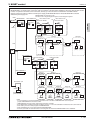
2-4-2. Rule of setting address
Unit
Address setting
Example
Note
7 8
9 0 1
2 3
10
1
S.D. H2i Y
4 5 6
4 5 6
01 ~ 50
2 3
7 8
9 0 1
Indoor unit
10
1
01
9
7 8
7 8
1
01
9
01
7 8
9
7 8
7 8
45 6
45 6
10
0
0
0
100
10
1
0
0
0
100
10
1
0
0
0
100
10
1
9 0 1
9 0 1
Lowest address within the indoor units connected to
the BC controller (Sub) plus 50.
The smallest address of indoor unit in the group + 100
The address of main remote controller + 50
The address automatically becomes "200" if it is set
as "00"
The smallest group No. to be managed + 200
The smallest group No. to be managed is changeable.
Settings are made on the initial screen of AG-150A-A.
Settings are made with setting tool of BM ADAPTER.
2 3
2 3
4 5 6
4 5 6
2
Fixed
7 8
1
7 8
45 6
45 6
45 6
10
Please reset one of them to an address between 51
and 99 when two addresses overlap.
The address automatically becomes "100" if it is set
as "01~ 50"
The place of "100" is fixed to "1"
01
100
000, 201 ~ 250
201 ~ 250
7 8
7 8
45 6
000, 201 ~ 250
01
2 3
PAC-YG50ECA
9
2 3
000, 201 ~ 250
01
45 6
Fixed
01
7 8
1
2 3
1
7 8
4 5 6
4 5 6
10
2 3
151 ~ 199, 200
7 8
7 8
7 8
9 0 1
2 3
Local remote controller
4 5 6
4 5 6
9 0 1
2 3
1
2 3
System controller
4 5 6
4 5 6
1
The smallest address of indoor unit in same refrigerant
system + 50
Assign sequential address numbers to the outdoor
units in one refrigerant circuit system. OC and OS are
automatically detected. (Note 2)
Please reset one of them to an address between 51
and 99 when two addresses overlap.
The address automatically becomes "100" if it is set
as "01~ 50"
The address of outdoor unit + 1
2 3
10
9
000, 201 ~ 250
LMAP04U-E
9 0 1
Fixed
AG-150A-A
GB-50ADA-A
GB-24A
EB-50GU-A
BAC-HD150
9 0 1
9
101 ~ 150
2 3
52 ~ 99, 100
9
ON/OFF remote
controller
1
2 3
ME, LOSSNAY
Remote controller
(Sub)
10
2 3
ME, LOSSNAY
Remote controller
(Main)
52 ~ 99, 100
9 0 1
2 3
BC controller
(Sub)
51 ~ 99, 100
(Note1)
2 3
BC controller
(Main)
7 8
9 0 1
Outdoor unit
Use the most recent address within the same group of
indoor units. Make the indoor units address connected
to the BC controller (Sub) larger than the indoor units
address connected to the BC controller (Main).
If applicable, set the sub BC controllers in an PURY
system in the following order:
(1) Indoor unit to be connected to the BC controller (Main)
(2) Indoor unit to be connected to the BC controller (No.1 Sub)
(3) Indoor unit to be connected to the BC controller (No.2 Sub)
Set the address so that (1)<(2)<(3)
10
1
Note1: To set the address to "100", set it to "50"
Note2: Outdoor units OC and OS in one refrigerant circuit system are automatically detected.
OC and OS are ranked in descending order of capacity. If units are the same capacity, they are ranked in ascending
order of their address.
SYSTEM DESIGN
4 - 98
2. M-NET control
DATA U10
2-4-3. System examples
Factory setting
Original switch setting of the outdoors, indoors, controllers, LM-AP, and BM ADAPTER at shipment is as follows.
Outdoor unit
: Address: 00, CN41: ON (Jumper), DipSW2-1: OFF
Indoor unit
: Address: 00
ME remote controller : Address: 101
LM-AP
: Address: 247, CN41: ON (Jumper), DipSW1-2: OFF
BM ADAPTER
: Address: 000, CN41: ON (Jumper)
DipSW2-1(Outdoor) : When the System Remote Controller is used, all the Dip SW2-1 at the outdoor units should be
set to "ON". * Dip SW2-1 remains OFF when only LM-AP is used.
DipSW1-2(LM-AP)
: When the LM-AP is used together with System Remote Controller, DipSW1-2 at the LM-AP
should be set to "ON".
CN40/CN41
: Change jumper from CN41 to CN 40 at outdoor control board will activate central transmission
power supply to TB7;
(Change jumper at only one outdoor unit when activating the transmission power supply
without using a power supply unit.)
Change jumper from CN41 to CN 40 at LM-AP will activate transmission power supply to LM-AP
itself;
Power supply unit is recommended to use for a system having more than 1 outdoor unit,
because the central transmission power supply from TB7 of one of outdoor units is risking that
the outdoor unit failure may let down the whole system controller system.
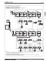
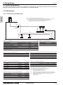
2-4-3-1. MA remote controller, Single-refrigerant-system, No System Controller
<Two outdoor units>
PUHY-HP-TSJMU
OC
OS
00
CN40
CN41
00
CN40
DipSW2-1
OFF
TB3
*1
To *1 or *2
<One outdoor unit>
PUHY-HP-TJMU
OC
CN41
DipSW2-1
OFF
TB3
00
CN40
CN41
DipSW2-1
OFF
TB3
*2
Group 1
Group 2
Group 3
Group 4
Indoor unit
00
TB5
SRU
00
TB15
TB5
00
TB15
TB5
00
TB15
TB5
00
TB15
TB5
TB15
*3
MA R/C
MA R/C
MA R/C MA R/C
(Main)
(Sub)
*3
Wireless R/C
*3 For Wireless R/C and Signal receiver unit (SRU), channel 1, 2 and 3 are selectable and should be set to same channel.
NOTE:
1. Outdoor units OC and OS in one refrigerant circuit system are automatically detected.
OC and OS are ranked in descending order of capacity. If units are the same capacity, they are ranked in ascending order
of their address.
2. No address setting is needed.
3. For a system having more than 16 indoor unit, confirm the need of Booster at 2-3 "System configuration restrictions".
SYSTEM DESIGN
4 - 99
S.D. H2i Y
Setting at the site
2. M-NET control
DATA U10
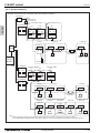
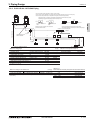
2-4-3-2. MA remote controller, Single-refrigerant-system, System Controller
<Two outdoor units>
PUHY-HP-TSJMU
OC
OS
51
S.D. H2i Y
CN40
CN41
52
CN40
DipSW2-1
ON
TB3
*1
<One outdoor unit>
PUHY-HP-TJMU
OC
CN41
DipSW2-1
ON
TB3
To *1 or *2
51
CN40
CN41
DipSW2-1
ON
TB3
*2
Group 1
Group 2
Group 3
Group 4
Indoor unit
01
TB5
201
02
TB15
TB5
03
TB15
TB5
04
TB15
TB5
05
TB15
TB5
TB15
SRU *3
SC
MA R/C
MA R/C
MA R/C MA R/C
(Main)
(Sub)
*3
Wireless R/C
*3 For Wireless R/C and Signal receiver unit (SRU), channel 1, 2 and 3 are selectable and should be set to same channel.
*SC can be connected to TB3 side or TB7 side;
Should SC connected to TB7 side, change Jumper from CN41 to CN40 at the Outdoor unit module so as to supply power to the SC.
NOTE:
1. Outdoor units OC and OS in one refrigerant circuit system are automatically detected.
OC and OS are ranked in descending order of capacity. If units are the same capacity, they are ranked in ascending order
of their address.
2. Address should be set to Indoor units and central controller.
3. For a system having more than 16 indoor unit, confirm the need of Booster at 2-3 "System configuration restrictions".
SYSTEM DESIGN
4 - 100
2. M-NET control
DATA U10
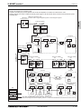
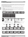
2-4-3-3. MA remote controller, Multi-refrigerant-system, System Controller at TB7 side, Booster for long M-NET wiring
PUHY-HP-TSJMU
OC
OS
TB7
TB7
51
CN40
52
CN41
CN40
ON
TB3
91
CN41
CN40
DipSW2-1
92
CN41
CN40
DipSW2-1
ON
CN40
DipSW2-1
ON
TB3
TB3
97
CN41
DipSW2-1
ON
ON
TB3
TB3
Group 1
CN41
S.D. H2i Y
DipSW2-1
PUHY-HP-TJMU
OC
TB7
PUHY-HP-TSJMU
OC
OS
TB7
TB7
Group 2
Group 21
Indoor unit
01
TB5
02
TB15
03
TB5
TB15
TB5
30
TB15
TB2
TB3
TB5
TB15
Transmission Booster
PAC-SF46EPA
SRU *1
PSU
MA R/C
Power supply
unit (PSU)
(PAC-SC51KUA)*2
MA R/C MA R/C
(Main)
(Sub)
*1
Wireless R/C
000 or 201
SC*3
Group 31
Group 32
Indoor unit
42
TB15
SRU *1
203
SC*3
Group 34
Group 35
LOSSNAY
41
TB5
Group 33
45
43
TB5
TB5
TB5
142
143
ME R/C
LOSSNAY
remote controller
46
TB15
MA R/C
TB5
TB15
MA R/C MA R/C
(Main)
(Sub)
*1
Wireless R/C
*1 For Wireless R/C and Signal receiver unit (SRU), channel 1, 2 and 3 are selectable and should be set to same channel.
*2 System controller should connect to TB7 at Outdoor and use power supply unit together in Multi-Refrigerant-System.
For AG-150A, 24V DC should be used with the PAC-SC51KUA.
*3 When multiple system controllers are connected in the system, set the controller with more functions than others as a "main"
controller and others as "sub".
TC-24A is for exclusive use as a "main" system controller and cannot be used as a "sub" system controller.
Make the setting to only one of the system controllers for "prohibition of operation from local remote controller".
NOTE:
1. Outdoor units OC and OS in one refrigerant circuit system are automatically detected.
OC and OS are ranked in descending order of capacity. If units are the same capacity, they are ranked in ascending order
of their address.
2. Address should be set to Indoor units, LOSSNAY and central controller.
3. M-NET power is supplied by the Outdoor unit at TB3, while Indoor unit and ME remote controller consume the M-NET power for
transmission use. The power balance is needed to consider for long M-NET wiring. Details refer to 2-3 "System configuration
restrictions".
SYSTEM DESIGN
4 - 101
2. M-NET control
DATA U10
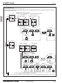
2-4-3-4. ME remote controller, Single-refrigerant-system, No system controller
<Two outdoor units>
PUHY-HP-TSJMU
OC
OS
51
S.D. H2i Y
CN40
CN41
52
CN40
DipSW2-1
OFF
TB3
*1
<One outdoor unit>
PUHY-HP-TJMU
OC
51
CN41
CN40
DipSW2-1
CN41
DipSW2-1
OFF
OFF
TB3
*2
TB3
Group 1
To *1 or *2
Group 2
Group 3
Group 4
Indoor unit
01
02
TB5
03
TB5
04
TB5
05
TB5
TB5
101
102
104
ME R/C
ME R/C
ME R/C
105
155
ME R/C ME R/C
NOTE:
1. Outdoor units OC and OS in one refrigerant circuit system are automatically detected.
OC and OS are ranked in descending order of capacity. If units are the same capacity, they are ranked in ascending order of their
address.
2. Address should be set to Indoor units, system controller and ME remote controllers.
3. M-NET power is supplied by the Outdoor unit at TB3, while Indoor unit and ME R/C consume the M-NET power for transmission
use. The power balance is needed to consider for long M-NET wiring. Details refer to 2-3 "System configuration restrictions".
2-4-3-5. ME remote controller, Single-refrigerant-system, System controller, LOSSNAY
<Two outdoor units>
PUHY-HP-TSJMU
OC
OS
51
CN40
CN41
52
CN40
CN41
DipSW2-1
DipSW2-1
ON
ON
TB3
*1
<One outdoor unit>
PUHY-HP-TJMU
OC
TB3
51
CN40
CN41
DipSW2-1
ON
TB3
*2
To *1 or *2
Group 1
Group 2
Indoor unit
Group 4
Group 5
LOSSNAY
02
01
TB5
TB5
Group 3
04
03
TB5
TB5
05
TB5
201
101
102
103
104
SC
ME R/C
ME R/C
LOSSNAY
remote controller
ME R/C
105
155
ME R/C ME R/C
*SC can be connected to TB3 side or TB7 side;
Should SC connected to TB7 side, change Jumper from CN41 to CN40 at the Outdoor unit module so as to supply power to the SC.
NOTE:
1. Outdoor units OC and OS in one refrigerant circuit system are automatically detected.
OC and OS are ranked in descending order of capacity. If units are the same capacity, they are ranked in ascending order of their
address.
2. Address should be set to Indoor units, LOSSNAY central controller, ME remote controllers.
3. For a system having more than 16 indoor unit, confirm the need of Booster at 2-3 "System configuration restrictions".
SYSTEM DESIGN
4 - 102
2. M-NET control
DATA U10
2-4-3-6. ME remote controller, Multi-refrigerant-system, System Controller at TB 7side, LOSSNAY, Booster for long M-NET wiring
PUHY-HP-TSJMU
OC
OS
TB7
TB7
51
CN40
52
CN41
CN40
PUHY-HP-TJMU
OC
TB7
PUHY-HP-TSJMU
OC
OS
TB7
TB7
91
CN41
CN40
92
CN41
CN40
96
CN41
DipSW2-1
DipSW2-1
DipSW2-1
ON
ON
ON
ON
TB3
TB3
TB3
DipSW2-1
ON
TB3
TB3
Group 1
CN41
S.D. H2i Y
DipSW2-1
CN40
Group 2
Group 21
Indoor unit
01
TB5
201
SC
02
03
TB5
TB5
101
102
SC *2
ME R/C
ME R/C
Group 31
Group 32
Indoor unit
Power supply
unit (PSU)
(PAC-SC51KUA)
*1
203
TB5
130
Group 33
Group 34
Group 35
LOSSNAY
TB5
141
TB3
ME R/C
42
41
TB5
TB2
Transmission Booster
PAC-SF46EPA
202
PSU
30
142
44
43
TB5
TB5
143
LOSSNAY
remote controller
45
TB5
144
145
195
ME R/C ME R/C
ME R/C
ME R/C
ME R/C
SC *2
*1 System controller should connect to TB7 at Outdoor and use power supply unit together in Multi-Refrigerant-System.
For AG-150A-A, 24V DC should be used with the PAC-SC51KUA.
*2 When multiple system controllers are connected in the system, set the controller with more functions than others as a "main"
controller and others as "sub".
TC-24A, AG-150A-A, GB-50ADA-A and GB-24A are for exclusive use as a "main" system controller and cannot be used as a "sub"
system controller.
Make the setting to only one of the system controllers for "prohibition of operation from local remote controller".
NOTE:
1. Outdoor units OC and OS in one refrigerant circuit system are automatically detected.
OC and OS are ranked in descending order of capacity. If units are the same capacity, they are ranked in ascending order of their address.
2. M-NET power is supplied by the Outdoor unit at TB3, while Indoor unit and ME remote controller consume the M-NET power for
transmission use. The power balance is needed to consider for long M-NET wiring. Details refer to 2-3 "System configuration
restrictions".
SYSTEM DESIGN
4 - 103
2. M-NET control
DATA U10
2-4-3-7. ME remote controller, Multi-refrigerant-system, No Power supply unit
PUHY-HP-TSJMU
OC
OS
TB7
TB7
51
CN40 CN41
S.D. H2i Y
DipSW2-1
OFF
TB3
PUHY-HP-TJMU
OC
TB7
52
CN40
56
CN41
CN40
DipSW2-1
CN41
DipSW2-1
OFF
OFF
TB3
TB3
Group 1
01
02
Group 2
03
04
05
101
105
ME R/C
ME R/C
Group 4
Group 3
10
09
08
07
110
107
ME R/C
ME R/C
06
NOTE
It is necessary to change the connecter to CN40 on the outdoor unit control board (only one outdoor unit) when the group is set between other refrigerant systems.
It is necessary to set on the remote controller by manual when group sets on the different refrigerant system. Please refer to remote controller installation manual.
2-4-3-8. ME remote controller, Multi-refrigerant-system, System Controller at TB7 side, No Power supply unit
PUHY-HP-TSJMU
OC
OS
TB7
TB7
51
CN40 CN41
DipSW2-1
ON
TB3
PUHY-HP-TJMU
OC
TB7
52
CN40
56
CN41
CN40
DipSW2-1
CN41
DipSW2-1
ON
ON
TB3
TB3
Group 1
01
02
Group 2
03
04
05
201
101
105
SC
ME R/C
ME R/C
Group 4
10
Group 3
09
08
07
110
107
ME R/C
ME R/C
06
NOTE
It is necessary to change the connecter to CN40 on the outdoor unit control board (only one outdoor unit) when the group is set between other refrigerant systems.
It is necessary to set on the remote controller by manual when group sets on the different refrigerant system. Please refer to remote controller installation manual.
SYSTEM DESIGN
4 - 104
2. M-NET control
DATA U10
2-4-3-9. TG-2000A(*1)+AG-150A-A*2,GB-50ADA-A
AG-150A-A can control max. 50 indoor units;
GB-50ADA-A can control max. 50 indoor units;
TG-2000A can control max. 40 of AG-150A-A and GB-50ADA-A;*3
TG-2000A can control max. 2000 indoor units.
GB-50ADA-A
<Three outdoor units>
PUHY-P-TSJMU/YSJMU
OC
000
PSU
OS1
TB7
51
CN40
CN41
OS2
TB7
52
CN40
OC
TB7
53
CN41
CN40
OS1
TB7
51
CN41
CN40
<One outdoor unit>
PUHY-P-TJMU/YJMU
OC
TB7
52
CN41
CN40
S.D. H2i Y
TB7
<Two outdoor units>
PUHY-P-TSJMU/YSJMU
51
CN41
CN40
CN41
(PAC-SC51KUA)
DipSW2-1
ON
TB3
DipSW2-1
DipSW2-1
ON
ON
TB3
DipSW2-1
DipSW2-1
ON
TB3
TB3
Group 1
DipSW2-1
ON
ON
TB3
TB3
Group 2
Group 40
Indoor unit
01
HUB
02
TB5
TB15
03
TB5
TB15 TB5
42
TB15 TB2
TB3 TB5
Transmission Booster
PAC-SF46EPA
SRU *1
MA R/C
PC with
TG-2000A
LAN
TB15
MA R/C MA R/C
(Main)
(Sub)
*1
Wireless R/C
AG-150A-A
PUHY-P-TSJMU/YSJMU
OC
000
TB7
OS1
TB7
51
24VDC
CN40
CN41
(PAC-SC51KUA)
ON
TB3
OS2
TB7
52
CN40
DipSW2-1
PSU
PUHY-P-TSJMU/YSJMU
CN41
OC
TB7
53
CN40
OS1
TB7
91
CN41
CN40
OC
TB7
92
CN41
CN40
96
CN41
DipSW2-1
DipSW2-1
DipSW2-1
DipSW2-1
ON
ON
ON
ON
TB3
TB3
TB3
Group 1
PUHY-P-TJMU/YJMU
CN40
CN41
DipSW2-1
ON
TB3
TB3
Group 2
Group 21
Indoor unit
01
02
TB5
TB5
101
102
ME R/C
ME R/C
Group 31
Group 32
Indoor unit
TB3
TB5
Transmission Booster
PAC-SF46EPA
130
ME R/C
Group 33
42
TB5
30
TB2
Group 34
Group 35
LOSSNAY
41
NOTE
03
TB5
TB5
141
142
ME R/C
ME R/C
44
43
TB5
TB5
143
LOSSNAY
remote controller
45
TB5
144
ME R/C
145
195
ME R/C ME R/C
*1 TG-2000A (Ver.5.5 or later) supports AG-150A-A (Ver.1 series).
TG-2000A (Ver. 6.1 or later) supports AG-150A-A (Ver. 2.1 or later) connected with the expansion controller (EC).
TG-2000A (Ver. 6.3 or later) supports GB-50ADA-A.
*2 AG-150A-A (Ver.1 series) does not support the expansion controller (EC).
*3 When AG-150A-A connected with the expansion controller (EC) is connected, the number of EC will be the maximum controllable number.
TG-2000A can control up to 40 EC or AG-150A-A without EC connection.
SYSTEM DESIGN
4 - 105
2. M-NET control
DATA U10
2-4-3. System examples
2-4-3-10. AG-150A-A + PAC-YG50ECA (Expansion controller)
AG-150A-A can control max. 150 indoor units/ via expansion controllers.
AG-150A-A
TB3
24VDC
PAC-YG50ECA
Power supply unit
(PAC-SC51KUA)
<Two outdoor units>
PUHY-HP-TSJMU
OC
S.D. H2i Y
000
CN40
CN41
TB7
OS
TB7
51
CN40
CN41
OC
TB7
52
CN40
DipSW2-1
ON
TB3
<One outdoor unit>
PUHY-HP-TJMU
51
CN41
CN40
DipSW2-1
CN41
DipSW2-1
ON
ON
TB3
TB3
Group 1
Group 2
Group 40
Indoor unit
01
HUB
02
TB5
TB15
03
TB5
TB15 TB5
42
TB15 TB2
TB3 TB5
Transmission Booster
PAC-SF46EPA
SRU *1
MA R/C
PC with
Browser
LAN
TB15
MA R/C MA R/C
(Main)
(Sub)
*1
Wireless R/C
PAC-YG50ECA
000
CN40
CN41
PUHY-HP-TSJMU
OC
TB7
PUHY-HP-TJMU
OS
TB7
51
CN40
PAC-YG50ECA
000
CN40
CN41
CN41
OC
TB7
52
CN40
91
CN41
DipSW2-1
DipSW2-1
ON
ON
TB3
CN40
CN41
DipSW2-1
ON
TB3
TB3
Group 1
Group 2
Group 21
Indoor unit
01
02
TB5
TB5
03
TB5
101
102
ME R/C
ME R/C
Group 31
Group 32
Indoor unit
TB5
TB5
130
ME R/C
Group 33
Group 34
Group 35
ME R/C
44
43
TB5
142
ME R/C
TB3
Transmission Booster
PAC-SF46EPA
42
141
TB2
LOSSNAY
41
TB5
30
TB5
143
LOSSNAY
remote controller
45
TB5
144
ME R/C
145
195
ME R/C ME R/C
NOTE
When connecting AG-150A-A to PAC-YG50ECA, TB2 for power supply unit does not need to be connected to AG-150A-A.
*1 For Wireless R/C and Signal receiver unit (SRU), channel 1, 2 and 3 are selectable and should be set to same channel.
SYSTEM DESIGN
4 - 106
2. M-NET control
DATA U10
2-4-3-11. LM-AP
LM-AP can transmit max. 50 indoor units;
If system controller (SC) is used, DipSW1-2 at LM-AP and DipSW2-1 at Outdoor unit should set to "ON".
Change Jumper from CN41 to CN40 to activate power supply to LM-AP itself for those LM-AP connected without system
controller (SC).
LM-AP can transmit for max.
LM-AP(01) 50 indoor units in single-refrigerant-system or multi-refrigerant-system.
identified by Neuron ID
247
OC
TB7
DipSW1-2
OS
TB7
51
OFF
CN40
S.D. H2i Y
PUHY-HP-TSJMU
CN40 CN41
52
CN41
CN40
DipSW2-1
CN41
DipSW2-1
OFF
TB3
OFF
TB3
Group 1
Group 2
Group 40
Indoor unit
01
02
TB5
TB15
03
TB5
42
TB15 TB5
TB15
AG-150A-A
Power supply unit
(PAC-SC51KUA)
24VDC
PSU
TB3 TB5
TB15
Transmission Booster
PAC-SF46EPA
SRU *1
000
TB2
MA R/C
MA R/C MA R/C
(Main) (Sub)
*1
LONWORKS®
Wireless R/C
LM-AP(02)
identified by Neuron ID
247
CN40 CN41
DipSW1-2
ON
PUHY-HP-TSJMU
OC
OS
TB7
TB7
CN40
51
CN41
DipSW2-1
ON
TB3
CN40
PUHY-HP-TSJMU
OC
OS
TB7
TB7
52
CN41
CN40
DipSW2-1
CN41
CN40
DipSW2-1
ON
ON
TB3
TB3
Group 1
91
PUHY-HP-TJMU
OC
TB7
92
CN40
CN41
DipSW2-1
96
CN41
DipSW2-1
ON
ON
TB3
TB3
Group 2
Group 21
Indoor unit
01
TB5
02
TB5
101
102
ME R/C
ME R/C
Group 31
Indoor unit
Group 32
41
42
PC
30
TB2
TB3
TB5
Transmission Booster
PAC-SF46EPA
130
ME R/C
Group 33
Group 34
Group 35
LOSSNAY
TB5
TB5
03
TB5
44
43
TB5
TB5
45
TB5
LONWORKS® card
®
LONWORKS card
LONWORKS® card
141
142
ME R/C
ME R/C
143
LOSSNAY
remote controller
144
ME R/C
145
195
ME R/C ME R/C
For other equipments (Lighting, security, elevator etc.)
*1 For Wireless R/C and Signal receiver unit (SRU), channel 1, 2 and 3 are selectable and should be set to same channel.
SYSTEM DESIGN
4 - 107
2. M-NET control
DATA U10
2-4-3-12. BM ADAPTER
BM ADAPTER can transmit max. 50 indoor units;
Change Jumper from CN41 to CN40 to activate power supply to BM ADAPTER itself for those BM ADAPTER connected
without the power supply unit.
BM ADAPTER(01)
<Two outdoor units>
PUHY-HP-TSJMU
000
S.D. H2i Y
HUB
BM ADAPTER can transmit for max.
50 indoor units in single-refrigerant-system or multi-refrigerant-system.
CN40 CN41
OC
TB7
<One outdoor unit>
PUHY-HP-TJMU
OS
TB7
51
CN40
OC
TB7
52
CN41
CN40
DipSW2-1
51
CN41
CN40
DipSW2-1
ON
TB3
CN41
DipSW2-1
ON
ON
TB3
TB3
Group 1
Group 2
Group 40
Indoor unit
01
02
TB5
TB15
03
TB5
TB15 TB5
42
TB15
TB2
TB3 TB5
TB15
Transmission Booster
PAC-SF46EPA
SRU *1
MA R/C
MA R/C MA R/C
(Main) (Sub)
*1
BACnet ®
Wireless R/C
BM ADAPTER(02)
000
CN40 CN41
PUHY-HP-TSJMU
OC
OS
TB7
TB7
CN40
51
CN41
CN40
PUHY-HP-TJMU
OC
TB7
52
CN41
DipSW2-1
DipSW2-1
ON
ON
TB3
CN40
91
CN41
DipSW2-1
TB3
ON
TB3
Group 1
Group 2
Group 21
Indoor unit
01
TB5
02
TB5
102
ME R/C
ME R/C
Group 32
HUB
TB2
TB3
TB5
Transmission Booster
PAC-SF46EPA
130
ME R/C
Group 33
Group 34
Group 35
LOSSNAY
41
TB5
30
TB5
101
Group 31
Indoor unit
03
42
TB5
141
142
ME R/C
ME R/C
44
43
TB5
TB5
143
LOSSNAY
remote controller
45
TB5
144
ME R/C
145
195
ME R/C ME R/C
For other equipments (Lighting, security, elevator etc.)
*1 For Wireless R/C and Signal receiver unit (SRU), channel 1, 2 and 3 are selectable and should be set to same channel.
SYSTEM DESIGN
4 - 108
2. M-NET control
DATA U10
2-4-3-13. BM ADAPTER + PAC-YG50ECA (Expansion controller)
BM ADAPTER*1 can transmit max. 150 indoor units via expansion controllers (PAC-YG50ECA). When the dual-set-point function
is used, no expansion controllers can be connected, and only up to 50 units can be controlled from each BAC-HD150.
Change Jumper from CN41 to CN40 to activate power supply to BM ADAPTER itself for those BM ADAPTER connected
without the power supply unit.
BM ADAPTER can transmit for max.
50 indoor units in single-refrigerant-system or multi-refrigerant-system.
LAN1
BM ADAPTER
BACnet ®
PAC-YG50ECA *4
000
000
CN40 CN41
CN40 CN41
<Two outdoor units>
PUHY-HP-TSJMU
OS
TB7
51
CN40
LAN2
OC
TB7
52
CN41
CN40
DipSW2-1
51
CN41
CN40
DipSW2-1
ON
TB3
S.D. H2i Y
OC
TB7
<One outdoor unit>
PUHY-HP-TJMU
CN41
DipSW2-1
ON
ON
TB3
TB3
Group 1
Group 2
Group 40
Indoor unit
01
02
TB5
TB15
03
TB5
TB15 TB5
42
TB15
TB2
TB3 TB5
TB15
LAN
Transmission Booster
PAC-SF46EPA
SRU *2
MA R/C
MA R/C MA R/C
(Main) (Sub)
HUB
*2
Wireless R/C
PAC-YG50ECA *4
000
CN40 CN41
PUHY-HP-TSJMU
OC
OS
TB7
TB7
CN40
51
CN41
CN40
52
CN41
DipSW2-1
DipSW2-1
ON
ON
TB3
PUHY-HP-TJMU
OC
TB7
CN40
91
CN41
DipSW2-1
ON
TB3
TB3
PAC-YG50ECA *4
000
Group 1
Group 2
Group 21
Indoor unit
01
TB5
AG-150A-A *3,*5
24VDC
TB3
Power supply unit
(PAC-SC51KUA)
02
TB5
101
102
ME R/C
ME R/C
Group 31
Indoor unit
Group 32
41
42
TB5
03
TB5
30
TB2
TB3
TB5
Transmission Booster
PAC-SF46EPA
130
ME R/C
Group 33
Group 34
Group 35
LOSSNAY
TB5
TB5
141
142
ME R/C
ME R/C
44
43
TB5
143
LOSSNAY
remote controller
45
TB5
144
ME R/C
145
195
ME R/C ME R/C
NOTE
• It is not necessary to connect the M-NET transmission line to the TB3 on BM ADAPTER. Leave the power
jumper of BM ADAPTER connected to CN41.
*1 BM ADAPTER (Ver.2.00 or later) supports the expansion controller.
*2 For Wireless R/C and Signal receiver unit (SRU), channel 1, 2 and 3 are selectable and should be set to same channel.
*3 AG-150A-A (Ver.2.30 or later) supports the BM ADAPTER.
*4 PAC-YG50ECA (Ver.1.30 or later) supports the BM ADAPTER.
*5 Consult your dealer for restrictions when connecting both AG-150A-A and BM ADAPTER to PAC-YG50ECA.
SYSTEM DESIGN
4 - 109
3. Piping Design
DATA U10
3-1. R410A Piping material
3. Piping Design
The maximum operation pressure of R410A air conditioner is 4.15 MPa [601 psi]. The refrigerant piping should ensure the safety
under the maximum operation pressure. You shall follow the local industrial standard.
3-2. Piping Design
3-2-1. PUHY-HP-72, 96TJMU Piping
S.D. H2i Y
OU
Note1. No joint after Header; Piping direct to Indoor Unit from Header;
Note2. If the A/C system is designed to use Cooling-mode under Outside temperature 10°C [50°F], H'<=40m [131ft.];
Note3. As bents cause pressure loss on transportation of refrigerant, fewer bents design is better;
Piping length needs to consider the actual length and equivalent length which bents are counted.
Equivalent piping length = Actual piping length + "M" x Quantity of bent.
A
Header
B
d
H'
H
The first joint
C
a
b
c
IU
IU
IU
IU
L1
L2
h
D
e
f
IU
IU
Joint
g
IU
Fig. 3-2-1A Piping scheme
Table3-2-1-1. Piping length
Item
Total piping length
Farthest IU from OU (L1)
Farthest IU from first joint (L2)
Height between OU and IU (OU above IU)
Height between OU and IU (OU under IU)
Height between IU and IU
IU : Indoor unit , OU : Outdoor unit
Piping in the figure
A+B+C+D+a+b+c+d+e+f+g
A+C+D+g / A+B+d
C+D+g / B+d
H
H'
h
Max. length
300 [984']
150 [492']
40 [131']
50 [164']
40 [131']
15 [49']
(m [ft.]) Table3-2-1-2. Bent equivalent length "M"
Max. equivalent length
Outdoor Model
M (m/bends [ft./bends])
PUHY-HP72TJMU
0.30 [0.99]
PUHY-HP96TJMU
0.35 [1.15]
175 [574']
40 [131']
-
OU: Outdoor Unit, IU: Indoor Unit
Table3-2-1-3. Piping "A" size selection rule
Outdoor and the first joint
PUHY-HP72TJMU=CMY-Y102SS-G2
PUHY-HP96TJMU=CMY-Y102LS-G2
Pipe(Liquid)
ø12.70 [1/2"]
ø12.70 [1/2"]
(mm [in.])
Pipe(Gas)
ø19.05 [3/4"]
ø22.20 [7/8"]
Table3-2-1-6. R410A Selection criteria for joints (second and successive branches)
Total down-stream Indoor capacity
Joint
~ P72
CMY-Y102SS-G2
P73 ~ P144
CMY-Y102LS-G2
P145 ~ P234
CMY-Y202S-G2
P235 ~
CMY-Y302S-G2
*Concerning detailed usage of joint parts, refer to its Installation Manual.
Table3-2-1-4. Piping "B","C","D"size selection rule
Total down-stream Indoor capacity
Pipe(Liquid)
~ P54
ø9.52 [3/8"]
P55 ~ P72
ø9.52 [3/8"]
P73 ~ P108
ø9.52 [3/8"]
P109 ~ P144
ø12.70 [1/2"]
P145 ~ P234
ø15.88 [5/8"]
(mm [in.])
Pipe(Gas)
ø15.88 [5/8"]
ø19.05 [3/4"]
ø22.20 [7/8"]
ø28.58 [1-1/8"]
ø28.58 [1-1/8"]
Table3-2-1-7. R410A Header selection rule
4-branch Header 8-branch Header 10-branch Header
CMY-Y104C-G CMY-Y108C-G CMY-Y1010C-G
Total down-stream Indoor capacity <=P72
<=P144
<=P234
* CMY-Y104C-G can directly connect PUHY-HP72TJMU, but can NOT directly connect PUHY-HP96TJMU or above;
* CMY-Y108C-G can directly connect PUHY-HP72-144T(S)JMU, but can NOT directly connect PUHY-HP192TSJMU
* CMY-Y1010C-G can directly connect PUHY-HP72-192T(S)JMU;
* CMY-Y104C-G can NOT connect P72, P96 Indoor, but CMY-Y108, Y1010C-G can do;
* Concerning detailed usage of Header parts, refer to its Installation Manual.
Note4.
Table3-2-1-5. Piping "a","b","c","d","e","f","g"size selection rule
Indoor Unit size
Pipe(Liquid)
P06,P08,P12,P15,P18
ø6.35 [1/4"]
P24,P27,P30,P36,P48,P54
ø9.52 [3/8"]
P72
ø9.52 [3/8"]
P96
ø9.52 [3/8"]
(mm [in.])
Pipe(Gas)
ø12.70 [1/2"]
ø15.88 [5/8"]
ø19.05 [3/4"]
ø22.20 [7/8"]
Note5.
Note6.
Indoor capacity is described as its model size;
For example, PEFY-P08NMAU-E3, its capacity is P06;
Total down-stream Indoor capacity is the summary of the model size of Indoors downstream.
For example, PEFY-P06NMAU-E3+PEFY-P08NMAU-E3: Total Indoor capacity=P06+P08=P14
Piping sized determined by the Total down-stream indoor capacity is NOT necessary
to be bigger than the up-stream one.
i.e. A>=B; A>=C>=D
SYSTEM DESIGN
4 - 110
3. Piping Design
DATA U10
3-2-2. PUHY-HP144-192TSJMU Piping
Note1. No joint after Header; Piping direct to Indoor Unit from Header;
Note2. If the A/C system is designed to use cooling-mode under outside temperature 10°C [50°F], H’<=40m [131ft].
Note3. As bents cause pressure loss on transportation of refrigerant, fewer bents design is better;
Piping length needs to consider the actual length and equivalent length which bents are counted.
Equivalent piping length=Actual piping length+"M" x Quantity of bent.
OU
OU
OK
Trap (gas
pipe only)
NO
h2
S
2m [6.56ft] To indoor unit 2m [6.56ft] max To indoor unit
Upward To indoor unit
incline
Install the pipes from the outdoor unit to the branch
joint with a downward incline.
If the length of pipe between the branch joint and outdoor
unit exceeds 2m [6.56ft], provide at rap at a distance 2m [6.56ft] or
less from the branch joint.
Header
Capped
B
1st joint
Outdoor Twinning Kit
CMY-Y100CBK3
C
L1
L2
D
a
b
c
IU
IU
IU
E
d
e
f
IU
IU
IU
Joint
g
h1
H' (OU under IU)
H (OU above IU)
A
IU
Fig. 3-2-1B Piping scheme
Table3-2-2-1. Piping length
Item
Total piping length
Distance between OU and OU
Height between OU and OU
Farthest IU from OU (L1)
Farthest IU from the first joint (L2)
Height between OU and IU (OU above IU)
Height between OU and IU (OU under IU)
Height between IU and IU
IU : Indoor unit , OU : Outdoor unit
(m [ft.])
Piping in the figure
Max. length Max. equivalent length
S+T+A+B+C+D+E+a+b+c+d+e+f+g 300 [984']
S+T
10[32']
h2
0.1[0.3']
S(T)+A+C+D+E+g / S(T)+A+B+c 150 [492']
175 [574']
C+D+E+g / B+c
40 [131']
40 [131']
H
50 [164']
H'
40 [131']
h1
15 [49']
-
Table3-2-2-2. Bent equivalent length "M"
Outdoor Model
M (m/bends [ft./bends])
PUHY-HP144TSJMU
0.50 [1.64]
PUHY-HP192TSJMU
0.50 [1.64]
OU: Outdoor Unit, IU: Indoor Unit
Table3-2-2-3. Piping "A" size selection rule
Outdoor unit
Twinning kit and the first joint
PUHY-HP144-192TSJMU CMY-Y100CBK3=CMY-Y202S-G2
For Piping size "S","T", please refer to specification of the Twinning kit CMY-Y100CBK2
external drawing.
Table3-2-2-4.
(mm [in.]) R410A Selection criteria for joints (second and successive branches)
Total down-stream Indoor capacity
Joint
Pipe(Liquid)
Pipe(Gas)
~ P72
CMY-Y102SS-G2
ø15.88[5/8"] ø28.58[1-1/8"]
P73 ~ P144
CMY-Y102LS-G2
at the Outdoor unit's
P145 ~ P234
CMY-Y202S-G2
*Concerning detailed usage of joint parts, refer to its Installation Manual.
SYSTEM DESIGN
4 - 111
S.D. H2i Y
Downward To indoor unit
incline
T
3. Piping Design
DATA U10
3-3. Refrigerant charging calculation
At the time of shipping, the outdoor unit is charged with the refrigerant. As this charge does not include the amount needed
for extended piping, additional charging for each refrigerant line will be required on site. In order that future servicing may be
properly provided, always keep a record of the size and length of each refrigerant line and the amount of additional charge
by writing it in the space provided on the outdoor unit.
(1) Calculation of additional refrigerant charge
S.D. H2i Y
Calculate the amount of additional charge based on the length of the piping extension and the size of the refrigerant
line.
Use the table to the below as a guide to calculating the amount of additional charging and charge the system
accordingly.
If the calculation results in a fraction of less than 0.1kg, round up to the next 0.1kg. For example, if the result of the
calculation was 12.38kg, round the result up to 12.4kg.
If the calculation results in a fraction of less than 1oz, round up to the next 1oz. For example, if the result of the
calculation was 435.1oz, round the result up to 436oz.
<Additional Charge>
Additional
refrigerant charge
(kg)
(oz)
Total length of liquid
=
(m) x 0.29 (kg/m)
(ft.) x 3.1 [oz/ft.]
Total length of liquid
+
(m) x 0.20 (kg/m)
(ft.) x 2.15 [oz/ft.]
Table3-2-3-1. Value of
Total capacity of connecting indoor units
Models
27
Models
28
54
Models
55 126
Models 127 144
Models 145 180
Models 181 234
Models 235
Total length of liquid
+
(m) x 0.12 (kg/m)
(ft.) x 1.29 [oz/ft.]
Total length of liquid
+
(m) x 0.06 (kg/m)
(ft.) x 0.65 [oz/ft.]
Total length of liquid
+
+
(m) x 0.024 (kg/m)
(ft.) x 0.26 [oz/ft.]
2.0 kg [71 oz]
2.5 kg [89 oz]
3.0 kg [106 oz]
3.5 kg [124 oz]
4.5 kg [159 oz]
5.0 kg [177 oz]
6.0 kg [212 oz]
Example: PUHY-HP96TJMU
m [kg]
A
ft. [oz]
Indoor 1: P48
A:
40 m
a:
10 m
2: P36
B:
10 m
b:
5m
3: P15
15 m
c:
10 m
4: P12
10 m
d:
10 m
5: P24
e:
10 m
The total length of liquid pipe of each size is as follows:
12.7 : A= 40 = 40 m
9.52 : B + C + D+ a + b + e = 10 + 15 + 10 + 10 + 5 + 10 = 60 m
6.35 : c +d = 10 + 10 = 20 m
Indoor 1: P48
A:
131ft.
32ft.
2: P36
B:
32ft.
b:
16ft.
3: P15
C:
49ft.
c:
32ft.
4: P12
D:
32ft.
d:
32ft.
5: P24
e:
32ft.
The total length of liquid pipe of each line is as follows:
A= 131 = 131ft.
+ a + b + e = 32 + 49 + 32 + 32 + 16 + 32 = 193ft.
Total capacity of connecting Indoor units Pt :
Pt = P48 + P36 + P15 + P12 + P24 = P135, therefore
Total capacity of connecting Indoor units Pt :
Pt = P48 + P36 + P15 + P12 + P24 = P135, therefore
B
= 3.5kg
C
= 124oz
e
D
a
b
c
d
P48
P36
P15
P12
P24
m [kg]
Additional
refrigerant charge
Total length of liquid
=
x 0.29 (kg/m)
+
0 (m) x 0.29 (kg/m)
(kg)
=
0
= 12.4 kg
or
Total length of liquid
x 0.20 (kg/m)
Total length of liquid
+
0 (m) x 0.20 (kg/m)
+
0
x 0.12 (kg/m)
Total length of liquid
+
40 (m) x 0.12 (kg/m)
+
40 x 0.12
x 0.06 (kg/m)
Total length of liquid
+
60 (m) x 0.06 (kg/m)
+
60 x 0.06
x 0.024 (kg/m)
+ 3.5
20 (m) x 0.024 (kg/m)
+
20 x 0.024
+ 3.5
ft. [oz]
Additional
refrigerant charge
(oz)
Total length of liquid
=
x 3.1 (oz/ft.)
Total length of liquid
+
0 (ft.) x 3.1 (oz/ft.)
=
0
= 436 [oz]
x 2.15 (oz/ft.)
Total length of liquid
+
0 (ft.) x 2.15 (oz/ft.)
+
0
x 1.29 (oz/ft.)
Total length of liquid
+
131 (ft.) x 1.29 (oz/ft.)
+
131 x 1.29
SYSTEM DESIGN
x 0.65 (oz/ft.)
Total length of liquid
+
193 (ft.)x 0.65 (oz/ft.)
+
193 x 0.65
x 0.26 (oz/ft.)
+ 124
64 (ft.) x 0.26 (oz/ft.)
+
64 x 0.26
+ 124
4 - 112
4. Outdoor Installation
DATA U10
4-1. Requirement on installation site
4. Outdoor Installation
1. No direct thermal radiation to the unit.
2. No possibility of annoying the neighbors by the sound of the unit.
Valves and refrigerant flow on the outdoor unit may generate noise.
Avoid the sites where strong winds blow.
With strength to bear the weight of the unit.
Drain flow from the unit is cared at heating mode.
Enough space for installation and service as shown at 4-2.
Avoid the sites where acidic solutions or chemical sprays (sulfur series) are used frequently.
The unit should be secure from combustible gas, oil, steam, chemical gas like acidic solution, sulfur gas and so on.
SYSTEM DESIGN
S.D. H2i Y
3.
4.
5.
6.
7.
8.
4 - 113
4. Outdoor Installation
DATA U10
4-2. Spacing
In case of single installation
• Secure enough space around the unit as shown in the figure.
<A> : Top view
A : Front
C : Back
<B> : Side view
B : Unit height
D : Air outlet guide (Procured at the site)
<C> : When there is little space up to an obstruction
(1) If the distance is 300 mm [11-13/16 in.] or more between the rear side and the wall
S.D. H2i Y
300*
[11-13/16]
450*
[17-23/32]
A
15* [19/32]
15* [19/32]
<A>
(2) If the distance is 100 mm [3-15/16 in.] or more between the rear side and the wall
100*
[3-15/16]
A
50* [1-31/32]
450*
[17-23/32]
50* [1-31/32]
<A>
500
H
A
[19-11/16]
B
h
H
h
(3) If the wall height (H) of the front, rear or side exceeds the wall height restriction
<B>
• When the height of the walls on the front, back or on the sides <H> exceeds the wall height limit as defined below,
add the height that exceeds the height limit <h> to the figures that are marked with an asterisk.
<Wall height limit> Front: Up to the unit height
Back: Up to 500mm [19-11/16 in.] from the unit bottom
Side: Up to the unit height
If the unit cannot be kept clear of the wall, please change the direction of the air outlet of the unit to blow against the wall to avoid air short cycle.
(4) If there are obstacles at the upper part of the unit
1000
[39-3/8]
45°
D
240
[9-15/32]
C
A
50 [1-31/32]
<C>
SYSTEM DESIGN
(Unit : mm [in.])
4 - 114
4. Outdoor Installation
DATA U10
In case of collective installation and continuous installation
A : Front
C : Wall height (H)
B : Must be open
C
B
C
A
C
A
C
100*
[3-15/16]
30
[1-3/16]
450*
[17-23/32]
C
300*
300*
[11-13/16] [11-13/16]
A
B
900
[35-7/16]
B
900
[35-7/16]
B
300*
[11-13/16]
300*
[11-13/16]
C
S.D. H2i Y
• When multiple units are installed adjacent to each other, secure enough space to allow for air circulation and
passageways between groups of units as shown in the figures.
• At least two sides must be left open.
• As with the single installation, add the height that exceeds the height limit <h> to the figures that are marked with
an asterisk.
• If there is a wall at both the front and the rear of the unit, install up to six units consecutively in the side direction and
provide a space of 1000mm or more as inlet space/passage space for each six units.
B
B
C
100
[3-15/16]
450*
[17-23/32]
A
B
A
C
450*
[17-23/32]
1000*
[39-3/8]
A
A
450
450
B
B
C
100*
[17-23/32] [17-23/32] [3-15/16]
15*
B
C
A
A
A
450
450
[17-23/32] [17-23/32]
(Unit : mm [in.])
SYSTEM DESIGN
4 - 115
4. Outdoor Installation
DATA U10
4-3. Piping direction
S.D. H2i Y
4-3-1. Lifting method
· When lifting the unit with ropes, run the ropes under the unit and use the lifting hole.
· Support the unit at four points with two ropes, and avoid giving mechanical shock.
· Suspension rope angle must be 40° or less, so as to avoid compressing fan guard.
· Use two ropes, each at least 8m [26 ft.] in length
· Use ropes strong enough to support the weight of the unit.
· Always suspend the unit from four corners. (It is dangerous to suspend a unit from two corners and must not be attempted.)
· Use protective pads to keep the ropes from scratching the panels on the unit.
1 HP72
2 HP96
8 [26]
8 [26]
40°
40°
8 [26]
8 [26]
CAUTION
Exercise caution when transporting products.
· Products weighing more than 20 kg [45 LBS] should not be carried alone.
· Do not carry the product by the PP bands.
· To avoid the risk of injury, do not touch the heat exchanger fins.
· Plastic bags may pose a risk of choking hazard to children. Tear plastic bags into pieces before disposing of them.
· When lifting and transporting outdoor units with ropes, run the ropes through lifting hole at the unit base. Securely
fix the unit so that the ropes will not slide off, and always lift the unit at four points to prevent the unit from falling.
SYSTEM DESIGN
4 - 116
4. Outdoor Installation
DATA U10
4-3-2. Installation
WARNING
Properly install the unit on a surface that can withstand the weight of
the unit. Unit installed on an unstable surface may fall and cause injury.
30mm [1-3/16in]
WARNING
Ta ke appropriate safety measures against strong winds and earthquakes to prevent the unit from falling.
Install the unit in such a
way that the corner of
the angle bracket at the
base of the unit shown
in the figure is securely
supported. The brackets
may bend if they are not
securely supported.
Fixing bracket for postinstallation-type anchor
bolts.
Ta ke into consideration the durability of the base, water drainage route (Drain water is discharged from outdoor units
during operation.), piping route, and wiring route when performing foundation work.
4-3-3. Anchor bolt positions
(Unit : mm [in.])
724±3 [(28-13/32~28-5/8)]
• Collective installation
724±3 [(28-13/32~28-5/8)]
<HP72, 96>
• Individual installation
A
(For maintenance)
A
30 [1-3/16]
190 [7-1/2]
30 [1-3/16]
190 [7-1/2]
A
A
Leave a minimum of 30 mm [1-3/16 in.] between units.
PUHY
A
SYSTEM DESIGN
HP72
HP96
760±2 [29-15/16(29-27/32~30)] 1060±2 [41-3/4(41-21/32~41-13/16)]
4 - 117
S.D. H2i Y
· Secure the unit with anchor bolts as shown in the figure below so that the unit will not topple over with strong wind or during an earthquake.
· Install the unit on a durable base made of such materials as concrete or angle steel.
· Ta ke appropriate anti-vibration measures (e.g., vibration damper pad, vibration isolation base) to keep vibrations and
noise from being transmitted from the unit through walls and floors.
· Install the unit in such a way that the corner of the angle bracket at the base of the unit shown in the figure below is
securely supported.
· Install the anchor bolt in such a way that the top end of the anchor bolt do not stick out more than 30 mm [1-3/16in].
· This unit is not designed to be anchored with post-installation-type anchor bolts, although by adding fixing brackets
anchoring with such type of anchor bolts becomes possible.
4. Outdoor Installation
DATA U10
4-3-4. Installation
When the pipes and/or cables are routed at the bottom of the unit, make sure that the through hole at the base of
the unit does not get blocked with the installation base.
When the pipes are routed at the bottom of the unit, the base should be at least 100 mm [3-15/16 in] in height.
· HP96
760 (29-15/16)
(Mounting pitch)
145 (5-23/32)
84 (3-5/16)
80
(3-5/32)
80
(3-5/32)
Bottom view
1060 (41-3/4)
(Mounting pitch)
760 (29-15/16)
18
(23/32)
80
(3-5/32)
(28-13/32~28-5/8)
(Mounting pitch)
Refrigerant service
valve <gas>
Refrigerant service
valve <liquid>
2X2-14(9/16)X20(13/16) Oval hole
(28-17/32)
724(721~727)
94
131 (5-3/16)
150 (5-29/32)
18
(23/32)
150 (5-29/32)
83 (3-9/32)
18
(23/32)
80
(3-5/32)
Refrigerant service
valve <gas>
(10-11/16) 271
(11-7/8) 301
(8-17/32) 216
(Unit : mm [in.])
(3-23/32)
Refrigerant service
valve <liquid>
2X2-14(9/16)X20(13/16) Oval hole
(3-5/8)
150 (5-29/32)
83(3-9/32)
(28-17/32)
18
724(721~727)
(28-13/32~28-5/8)
(23/32)
(Mounting pitch)
(760)(29-15/16)
(8-23/32) 221
(9-29/32) 251
(7-11/32) 186
145 (5-23/32)
86(3-13/32)
(Unit : mm [in.])
92
131 (5-3/16)
150 (5-29/32)
S.D. H2i Y
· HP72
Bottom view
Installation base parallel to the unit’s front panel
Installation base perpendicular to the unit’s front panel
4-3-5. Refrigerant pipe routing
The gaps around the edges of through holes for pipes and wires on the
unit allow water or mice to enter the unit and damage its parts. Close
these gaps with filler plates.
This unit allows two types of pipe routing:
• Bottom piping
• Front piping
CAUTION
To prevent small animals, water and snow from
entering the unit and damage its parts, close the
gap around the edges of through holes for pipes
and wires with filler plates.
Fill the gap at the site
Example of closure materials (field-supplied)
SYSTEM DESIGN
4 - 118
4. Outdoor Installation
DATA U10
4-3-6. Twinning on the outdoor unit side
The tilt angle of the twinning pipe
The tilt angle of the twinning pipe must be within ±15° with the horizontal plane.
Tilting the twinning pipe more than specified will cause damage to the unit.
The length of the straight part of the pipe before the branching
For the twinning kit, always use the accessory piping parts.
The length of the straight part of pipe connected in front of the
twinning pipe must be 500 mm (19 in) or longer.
(Connect the field piping so that the length of the straight part
of pipe connected in front of the twinning pipe can be 500 mm
(19 in) or longer.)
If the length is less than 500 mm (19 in), it will cause damage
to the unit.
The tilt angle of the reducer should be
within ±15° with the horizontal plane.
The piping connection
When connecting the twinning kit to the outdoor unit, note the following:
If the length of piping from the twinning kit to the outdoor unit is more than 2 m (6 ft),
install a trap within 2 m (6 ft) from the outdoor unit. The height of the trap must be 200
mm (7 in) or higher.
<2 m (6 ft) or less>
<More than 2 m (6 ft)>
Trap
(gas pipe only)
200 mm (7 in)
or over
To Indoor unit
To Indoor unit
2m (6 ft)
Less than 2 m (6 ft)
When installing the twinning kit in a higher position than the outdoor unit base, make
sure that the twinning kit is installed in a position lower than 200 mm (7 in) from the
outdoor unit base.
Outdoor unit 1
<PUHY-HP144TSJMU-A>
Outdoor unit 2
Twinning pipe1
To Indoor unit
200 mm (7 in)
or less
Outdoor unit 1
Outdoor unit 2
<PUHY-HP192TSJMU-A>
Twinning pipe 1
To indoor unit
200mm [7 in.]
or less
SYSTEM DESIGN
4 - 119
S.D. H2i Y
±15°
Note: See the following drawing for the fitting
position of the twinning pipe.
Reducer
4. Outdoor Installation
DATA U10
4-3-7. Twinning on the outdoor unit side
See the following drawing for connecting the pipes between the outdoor units.
S.D. H2i Y
<PUHY-HP144 TSJMU-A>
Field piping
Twinning kit
Field piping
The
le
mus ngth of
t be
t
500 he straig
mm
[19 i ht pipe
n.] o
r lon
ger
<PUHY-HP192TSJMU-A>
Field piping
Twinning kit
Field piping
The
le
mus ngth of
t be
t
500 he straig
mm
h
[19 i t pipe
n.] o
r lon
ger
CAUTION
The length of the straight pipe must be 500mm[19in.] or longer.
If not, it may cause improper operation.
SYSTEM DESIGN
4 - 120
4. Outdoor Installation
DATA U10
4-4. Weather countermeasure
• Snow hood
Unit : mm[in]
1206 [47-1/2]
906 [35-11/16]
800 [31-1/2]
A
(920)[36-1/4]
1324 [52-5/32]
B
(760)
[29-15/16]
B
B
B
H
B
86
[3-13/32]
1324 [52-5/32]
(1220)[48-1/16]
H
86
[3-13/32]
S.D. H2i Y
800 [31-1/2]
750 [29-17/32]
453
[17-27/32]
910 [35-27/32]
453
[17-27/32]
453
[17-27/32]
<Front view>
1210 [47-21/32]
<Front view>
453
[17-27/32]
453
760 [29-15/16] [17-27/32]
<Side view>
Outlet
Inlet
Note:
1.Height of frame base for snow damage prevention (H) shall be twice as high as expected snowfall. Width of frame base shall
not exceed that of the unit. The frame base shall be made of angle steel, etc., and designed so that snow and wind slip
through the structure. (If frame base is too wide, snow will be accumulated on it.)
2.Install unit so that wind will not directly lash against openings of inlet and outlet ducts.
3.Build frame base at customer referring to this figure.
Material: Galvanized steel plate 1.2T [1/16 in T]
Painting: Overall painting with polyester powder
Color: Munsell 5Y8/1 (same as that of unit)
4.When the unit is used in a cold region and the heating operation is continuously performed for a long time when the outside air
temperature is below freezing, install a heater to the unit base or take other appropriate measures to prevent water from
freezing on the base.
5.Do not use a snow hood made of stainless steel, which may cause the unit to rust. If the use of a stainless snow hood is the only
option, contact the sales office before installing it.
Countermeasure to wind
Referring to the figure shown below, take appropriate measures which will suit the actual situation of the place for installation.
Wind
Install the outdoor unit where seasonal
winds do not blow directly against the
unit, such as behind a building.
SYSTEM DESIGN
Install the outdoor unit to avoid having
seasonal winds against the front of air
outlet/inlet on the unit.
4 - 121
4. Outdoor Installation
DATA U10
4-5. Caution on selecting outdoor units
S.D. H2i Y
Consult your dealer when the following issues on Y system are the key concern.
· Warm air may flow out from the indoor unit during heating Thermo-OFF.
· Refrigerant flow sound may occur in the rooms with low background noise such as hotel rooms, hospital rooms,
bedrooms, or conference rooms.
To avoid the above issues on Y system, changing board settings on the indoor and outdoor units is required.
Ask AC&R Works for details.
SYSTEM DESIGN
4 - 122
5. Installation information
DATA U10
5-1. General precautions
5. Installation information
5-1-1. Usage
The air-conditioning system described in this Data Book is designed for human comfort.
This product is not designed for preservation of food, animals, plants, precision equipment, or art objects. To prevent
quality loss, do not use the product for purposes other than what it is designed for.
To reduce the risk of water leakage and electric shock, do not use the product for air-conditioning vehicles or vessels.
5-1-2. Installation environment
5-1-3. Backup system
In a place where air conditioner's malfunctions may exert crucial influence, it is recommended to have two or more systems of single outdoor units with multiple indoor units.
5-1-4. Unit characteristics
Heat pump efficiency depends on outdoor temperature. In the heating mode, performance drops as the outside air temperature drops. In cold climates, performance can be poor. Warm air would continue to be trapped near the ceiling and
the floor level would continue to stay cold. In this case, heat pumps require a supplemental heating system or air circulator. Before purchasing them, consult your local distributor for selecting the unit and system.
When the outdoor temperature is low and the humidity is high, the heat exchanger on the outdoor unit side tends to
collect frost, which reduces its heating performance. To remove the frost, Auto-defrost function will be activated and the
heating mode will temporarily stop for 3-10 minutes. Heating mode will automatically resume upon completion of defrost
process.
Air conditioner with a heat pump requires time to warm up the whole room after the heating operation begins, because
the system circulates warm air in order to warm up the whole room.
The sound levels were obtained in an anechoic room. The sound levels during actual operation are usually higher than
the simulated values due to ambient noise and echoes. Refer to the section on "SOUND LEVELS" for the measurement
location.
Depending on the operation conditions, the unit generates noise caused by valve actuation, refrigerant flow, and pressure changes even when operating normally. Please consider to avoid location where quietness is required.
For BC controller, it is recommended to unit to be installed in places such as ceilings of corridor, restrooms and plant
rooms.
The total capacity of the connected indoor units can be greater than the capacity of the outdoor unit. However, when the
connected indoor units operate simultaneously, each unit's capacity may become smaller than the rated capacity.
When the unit is started up for the first time within 12 hours after power on or after power failure, it performs initial startup
operation (capacity control operation) to prevent damage to the compressor. The initial startup operation requires 90
minutes maximum to complete, depending on the operation load.
5-1-5. Relevant equipment
Use an earth leakage breaker (ELB) with medium sensitivity, and an activation speed of 0.1 second or less.
Consult your local distributor or a qualified technician when installing an earth leakage breaker.
If the unit is inverter type, select an earth leakage breaker for handling high harmonic waves and surges.
Leakage current is generated not only through the air conditioning unit but also through the power wires. Therefore, the
leakage current of the main power supply is greater than the total leakage current of each unit. Take into consideration
the capacity of the earth leakage breaker or leakage alarm when installing one at the main power supply. To measure
the leakage current simply on site, use a measurement tool equipped with a filter, and clamp all the four power wires
together. The leakage current measured on the ground wire may not accurate because the leakage current from other
systems may be included to the measurement value.
Do not install a phase advancing capacitor on the unit connected to the same power system with an inverter type unit
and its equipment.
If a large current flows due to the product malfunctions or faulty wiring, both the earth leakage breaker on the product
side and the upstream overcurrent breaker may trip almost at the same time. Separate the power system or coordinate
all the breakers depending on the system's priority level.
SYSTEM DESIGN
4 - 123
S.D. H2i Y
Do not install any unit other than the dedicated unit in a place where the voltage changes a lot, large amounts of mineral
oil (e.g., cutting oil) are present, cooking oil may splash, or a large quantity of steam can be generated such as a kitchen.
Do not install the unit in acidic or alkaline environment.
Installation should not be performed in the locations exposed to chlorine or other corrosive gases. Avoid near a sewer.
To reduce the risk of fire, do not install the unit in a place where flammable gas may be leaked or inflammable material
is present.
This air conditioning unit has a built-in microcomputer. Take the noise effects into consideration when deciding the installation position. Especially in a place where antenna or electronic device are installed, it is recommended that the air
conditioning unit be installed away from them.
Install the unit on a solid foundation according to the local safety measures against typhoons, wind gusts, and earthquakes to prevent the unit from being damaged, toppling over, and falling.
5. Installation information
DATA U10
5-1-6. Unit installation
Your local distributor or a qualified technician must read the Installation Manual that is provided with each unit carefully
before performing installation work.
Consult your local distributor or a qualified technician when installing the unit. Improper installation by an unqualified
person may result in water leakage, electric shock, or fire.
Ensure there is enough space around each unit.
S.D. H2i Y
5-1-7. Optional accessories
Only use accessories recommended by Mitsubishi Electric. Consult your local distributor or a qualified technician when
installing them. Improper installation by an unqualified person may result in water leakage, electric leakage, system
breakdown, or fire.
Some optional accessories may not be compatible with the air conditioning unit to be used or may not suitable for the
installation conditions. Check the compatibility when considering any accessories.
Note that some optional accessories may affect the air conditioner's external form, appearance, weight, operating
sound, and other characteristics.
5-1-8. Operation/Maintenance
Read the Instruction Book that is provided with each unit carefully prior to use.
Maintenance or cleaning of each unit may be risky and require expertise. Read the Instruction Book to ensure safety.
Consult your local distributor or a qualified technician when special expertise is required such as when the indoor unit
needs to be cleaned.
5-2. Precautions for Indoor unit
5-2-1. Operating environment
The refrigerant (R410A) used for air conditioner is non-toxic and nonflammable. However, if the refrigerant leaks, the
oxygen level may drop to harmful levels. If the air conditioner is installed in a small room, measures must be taken to
prevent the refrigerant concentration from exceeding the safety limit even if the refrigerant should leak.
If the units operate in the cooling mode at the humidity above 80%, condensation may collect and drip from the indoor
units.
5-2-2. Unit characteristics
The return air temperature display on the remote controller may differ from the ones on the other thermometers.
The clock on the remote controller may be displayed with a time lag of approximately one minute every month.
The temperature using a built-in temperature sensor on the remote controller may differ from the actual room temperature due to the effect of the wall temperature.
Use a built-in thermostat on the remote controller or a separately-sold thermostat when indoor units installed on or in
the ceiling operate the automatic cooling/heating switchover.
The room temperature may rise drastically due to Thermo OFF in the places where the air conditioning load is large
such as computer rooms.
Be sure to use a regular filter. If an irregular filter is installed, the unit may not operate properly, and the operation noise
may increase.
The room temperature may rise over the preset temperature in the environment where the heating air conditioning load
is small.
5-2-3. Unit installation
For simultaneous cooling/heating operation type air conditioners (R2, H2i R2, WR2 series), the G-type BC controller
cannot be connected to the P144 outdoor unit model or above, and the G- and GA-type BC controllers cannot be connected to the P264 model or above. The GB- and HB-type BC controllers (sub) cannot be connected to the outdoor unit
directly, and be sure to use them with GA- and HA-type BC controllers (main).
The insulation for low pressure pipe between the BC controller and outdoor unit shall be at least 20 mm thick. If the unit
is installed on the top floor or in a high-temperature, high-humidity environment, thicker insulation may be necessary.
Do not have any branching points on the downstream of the refrigerant pipe header.
When a field-supplied external thermistor is installed or when a device for the demand control is used, abnormal stop of
the unit or damage of the electromagnetic contactor may occur. Consult your local distributor for details.
When indoor units operate a fresh air intake, install a filter in the duct (field-supplied) to remove the dust from the air.
The 4-way or 2-way Airflow Ceiling Cassette Type units that have an outside air inlet can be connected to the duct, but
need a booster fan to be installed at site. Refer to the chapter "Indoor Unit" for the available range for fresh air intake
volume.
Operating fresh air intake on the indoor unit may increase the sound pressure level.
SYSTEM DESIGN
4 - 124
5. Installation information
DATA U10
5-3. Precautions for Outdoor unit/Heat source unit
5-3-1. Installation environment
5-3-2. Circulating water
Follow the guidelines published by JRAIA (JRA-GL02-1994) to check the water quality of the water in the heat source
unit regularly.
A cooling tower and heat source water circuit should be a closed circuit that water is not exposed to the atmosphere.
When a tank is installed to ensure that the circuit has enough water, minimize the contact with outside air so that the
oxygen from being dissolved in the water should be 1 mg/L or less.
5-3-3. Unit characteristics
When the Thermo ON and OFF is frequently repeated on the indoor unit, the operation status of outdoor units may become unstable.
5-3-4. Relevant equipment
Provide grounding in accordance with the local regulations.
SYSTEM DESIGN
4 - 125
S.D. H2i Y
Outdoor unit with salt-resistant specification is recommended to use in a place where it is subject to salt air.
Even when the unit with salt-resistant specification is used, it is not completely protected against corrosion. Be sure to
follow the directions or precautions described in Instructions Book and Installation Manual for installation and maintenance. The salt-resistant specification is referred to the guidelines published by JRAIA (JRA9002).
Install the unit in a place where the flow of discharge air is not obstructed. If not, the short-cycling of discharge air may
occur.
Provide proper drainage around the unit base, because the condensation may collect and drip from the outdoor units.
Provide water-proof protection to the floor when installing the units on the rooftop.
In a region where snowfall is expected, install the unit so that the outlet faces away from the direction of the wind, and
install a snow guard to protect the unit from snow. Install the unit on a base approximately 50 cm higher than the expected snowfall. Close the openings for pipes and wiring, because the ingress of water and small animals may cause equipment damage. If SUS snow guard is used, refer to the Installation Manual that comes with the snow guard and take
caution for the installation to avoid the risk of corrosion.
When the unit is expected to operate continuously for a long period of time at outside air temperatures of below 0ºC,
take appropriate measures, such as the use of a unit base heater, to prevent icing on the unit base. (Not applicable to
the PUMY-P-NHMU series)
Install the snow guard so that the outlet/inlet faces away from the direction of the wind.
When the snow accumulates approximately 50 cm or more on the snow guard, remove the snow from the guard. Install
a roof that is strong enough to withstand snow loads in a place where snow accumulates.
Provide proper protection around the outdoor units in places such as schools to avoid the risk of injury.
A cooling tower and heat source water circuit should be a closed circuit that water is not exposed to the atmosphere.
When a tank is installed to ensure that the circuit has enough water, minimize the contact with outside air so that the
oxygen from being dissolved in the water should be 1 mg/L or less.
Install a strainer (50 mesh or more recommended) on the water pipe inlet on the heat source unit.
Interlock the heat source unit and water circuit pump.
Note the followings to prevent the freeze bursting of pipe when the heat source unit is installed in a place where the
ambient temperature can be 0ºC or below.
Keep the water circulating to prevent it from freezing when the ambient temperature is 0ºC or below.
Before a long period of non use, be sure to purge the water out of the unit.
5. Installation information
DATA U10
5-4. Precautions for Control-related items
S.D. H2i Y
5-4-1. Product specification
To introduce the MELANS system, a consultation with us is required in advance. Especially to introduce the electricity
charge apportioning function or energy-save function, further detailed consultation is required. Consult your local distributor for details.
Billing calculation for AG-150A-A, GB-50ADA-A, EB-50GU-A, TG-2000A, or the billing calculation unit is unique and
based on our original method. (Backup operation is included.) It is not based on the metering method, and do not use it
for official business purposes. It is not the method that the amount of electric power consumption (input) by air conditioner is calculated. Note that the electric power consumption by air conditioner is apportioned by using the ratio corresponding to the operation status (output) for each air conditioner (indoor unit) in this method.
In the apportioned billing function for AG-150A-A, GB-50ADA-A, and EB-50GU-A, use separate watthour meters for
A-control units, K-control units*1., and packaged air conditioner for City Multi air conditioners. It is recommended to use
an individual watthour meter for the large-capacity indoor unit (with two or more addresses).
When using the peak cut function on the AG-150A-A, GB-50ADA-A or EB-50GU-A, note that the control is performed
once every minute and it takes time to obtain the effect of the control. Take appropriate measures such as lowering the
criterion value. Power consumption may exceed the limits if AG-150A-A, GB-50ADA-A or EB-50GU-A malfunctions or
stops. Provide a back-up remedy as necessary.
The controllers cannot operate while the indoor unit is OFF. (No error)
Turn ON the power to the indoor unit when operating the controllers.
When using the interlocked control function on the AG-150A-A, GB-50ADA-A, EB-50GU-A, PAC-YG66DCA, or PACYG63MCA, do not use it for the control for the fire prevention or security. (This function should never be used in the way
that would put people's lives at risk.) Provide any methods or circuit that allow ON/OFF operation using an external
switch in case of failure.
5-4-2. Installation environment
The surge protection for the transmission line may be required in areas where lightning strikes frequently occur.
A receiver for a wireless remote controller may not work properly due to the effect of general lighting. Leave a space of
at least 1 m between the general lighting and receiver.
When the Auto-elevating panel is used and the operation is made by using a wired remote controller, install the wired
remote controller to the place where all air conditioners controlled (at least the bottom part of them) can be seen from
the wired remote controller. If not, the descending panel may cause damage or injury, and be sure to use a wireless
remote controller designed for use with elevating panel (sold separately).
Install the wired remote controller (switch box) to the place where the following conditions are met.
Where installation surface is flat
Where the remote controller can detect an accurate room temperature
The temperature sensors that detect a room temperature are installed both on the remote controller and indoor unit.
When a room temperature is detected using the sensor on the remote controller, the main remote controller is used to
detect a room temperature. In this case, follow the instructions below.
Install the controller in a place where it is not subject to the heat source.
(If the remote controller faces direct sunlight or supply air flow direction, the remote controller cannot detect an accurate
room temperature.)
Install the controller in a place where an average room temperature can be detected.
Install the controller in a place where no other wires are present around the temperature sensor.
(If other wires are present, the remote controller cannot detect an accurate room temperature.)
To prevent unauthorized access, always use a security device such as a VPN router when connecting
AG-150A-A, GB-50ADA-A, EB-50GU-A or TG-2000A to the Internet.
*1.EB-50GU-A cannot be used to control K-control units.
SYSTEM DESIGN
4 - 126
6. Caution for refrigerant leakage
DATA U10
The installer and/or air conditioning system specialist shall secure safety against refrigerant leakage according to local regulations or standards.
The following standard may be applicable if no local regulation or standard is available.
6. Caution for refrigerant leakage
6-1. Refrigerant property
R410A refrigerant is harmless and incombustible. The R410A is heavier than the indoor air in density. Leakage of the refrigerant in a room
has possibility to lead to a hypoxia situation. Therefore, the Critial concentration specified below shall not be exceeded even if the leakage
happens.
Critical concentration
The Critical concentration is subject to ISO5149, EN378-1.
For the CITY MULTI system, the concentration of refrigerant leaked should not have a chance to exceed the Critical concentration in
any situntion.
6-2. Confirm the Critical concentration and take countermeasure
The maximum refrigerant leakage concentration (Rmax) is defined as the result of the possible maximum refrigerant weight (Wmax)
leaked into a room divided by its room capacity (V). It is referable to Fig.6-1. The refrigerant of Outdoor unit here includes its original
charge and additional charge at the site.
The additional charge is calculated according to “3-3. Refrigerant charging calculation” and shall not be over charged at the site.
Procedure 6-2-1~3 tells how to confirm maximum refrigerant leakage concentration (Rmax) and how to take countermeasures against
a possible leakage.
Outdoor unit (No.1)
Outdoor unit (No.1)
Outdoor unit (No.2)
Flow of refrigerant
Indoor unit
Flow of refrigerant
Flow of refrigerant
Indoor unit
Maximum refrigerant leakage concentration (Rmax)
Rmax=Wmax / V (kg/m3)
Maximum refrigerant leakage concentration (Rmax)
Rmax=Wmax / V (kg/m3) W1: Refrigerant weight of Outdoor unit No.1
where, Wmax=W1+W2 W2: Refrigerant weight of Outdoor unit No.2
Fig. 6-1 The maximum refrigerant leakage concentration
6-2-1.Find the room capacity (V),
If a room having total opening area more than 0.15% of the floor area at a low position with another room/space, the two rooms/space are
considered as one. The total space shall be added up.
6-2-2.Find the possible maximum leakage (Wmax) in the room. If a room has Indoor unit(s) from more than 1 Outdoor unit, add up the refrigerant of the Outdoor units.
6-2-3.Divide (Wmax) by (V) to get the maximum refrigerant leakage concentration (Rmax).
6-2-4.Find if there is any room in which the maximum refrigerant leakage concentration (Rmax) is over 0.44kg/m3.
If no, then the CITY MULTI is safe against refrigerant leakage.
If yes, following countermeasure is recommended to do at site.
Countermeasure 1: Let-out (making V bigger)
Design an opening of more than 0.15% of the floor area at a low position of the wall to let out the refrigerant whenever leaked.
e.g.make the upper and lower seams of door big enough.
Countermeasure 2: Smaller total charge (making Wmax smaller)
e.g.Avoid connecting more than 1 Outdoor unit to one room.
e.g.Using smaller model size but more Outdoor units.
e.g.Shorten the refrigerant piping as much as possible.
Countermeasure 3: Fresh air in from the ceiling (Ventilation)
As the density of the refrigerant is bigger than that of the air.Fresh air supply from the ceiling is better than air exhausting from the ceiling.
Fresh air supply solution refers to Fig.6-2~4.
Fresh air supply fan (always ON)
Refrigerant pipe
Refrigerant pipe (high pressure pipe)
Fresh air supply fan
Refrigerant pipe
to Outdoor unit
Indoor space
(Floor)
Opening
Opening
Sensor for refrigerant leakage (Oxygen sensor or refrigerant sensor).
[At 0.3m height from the floor]
Fig.6-2. Fresh air supply always ON
to Outdoor unit
Indoor unit
Indoor space
(Floor)
Refrigerant stop valve
to Outdoor unit
Indoor unit
Indoor space
Fresh air supply fan
Fig.6-3. Fresh air supply upon sensor action
Indoor unit
(Floor)
Opening
Sensor for refrigerant leakage (Oxygen sensor or refrigerant sensor).
[At 0.3m height from the floor]
Fig.6-4. Fresh air supply and refrigerant
shut-off upon sensor action
Note 1.Countermeasure 3 should be done in a proper way in which the fresh air supply shall be on whenever the leakage happens.
Note 2.In principle, MITSUBISHI ELECTRIC requires proper piping design, installation and air-tight testing after installation to avoid leakage happening.
In the area should earthquake happen, anti-vibration measures should be fully considered.
The piping should consider the extension due to the temperature variation.
SYSTEM DESIGN
4 - 127
S.D. H2i Y
Critical concentration hereby is the refrigerant concentration in which no human body would be hurt if immediate measures can be taken
when refrigerant leakage happens.
Critical concentration of R410A: 0.44kg/m3
(The weight of refrigeration gas per 1 m3 air conditioning space.);