1
DATA U10
CITY MULTI
SYSTEM DESIGN WR2 SERIES - 575V
1. Electrical work.................................................................................................................................................. 4 - 340
1-1.General cautions ....................................................................................................................................... 4 - 340
1-2.Power supply for Indoor unit and Heat source unit.................................................................................... 4 - 341
1-3.Power cable specifications ........................................................................................................................ 4 - 345
1-4.Power supply examples............................................................................................................................. 4 - 346
2. M-NET control.................................................................................................................................................. 4 - 348
2-1.Transmission cable length limitation.......................................................................................................... 4 - 348
2-2.Transmission cable specifications ............................................................................................................. 4 - 349
2-3.System configuration restrictions............................................................................................................... 4 - 350
2-4.Address setting.......................................................................................................................................... 4 - 353
3. Piping Design................................................................................................................................................... 4 - 366
3-1.R410A Piping material............................................................................................................................... 4 - 366
3-2.Piping Design ............................................................................................................................................ 4 - 366
3-3.Refrigerant charging calculation ................................................................................................................ 4 - 370
4. Installation........................................................................................................................................................ 4 - 371
4-1.Requirement on installation site ................................................................................................................ 4 - 371
4-2.Spacing...................................................................................................................................................... 4 - 371
4-3.Piping direction .......................................................................................................................................... 4 - 372
5. Installation information..................................................................................................................................... 4 - 373
5-1.General precautions .................................................................................................................................. 4 - 373
5-2.Precautions for Indoor unit ........................................................................................................................ 4 - 374
5-3.Precautions for Outdoor unit/Heat source unit .......................................................................................... 4 - 375
5-4.Precautions for Control-related items ........................................................................................................ 4 - 376
6. Caution for refrigerant leakage ........................................................................................................................ 4 - 377
6-1.Refrigerant property................................................................................................................................... 4 - 377
6-2.Confirm the Critical concentration and take countermeasure.................................................................... 4 - 377
SYSTEM DESIGN WR2 SERIES - 575V
4 - 339
1. Electrical work
DATA U10
1-1. General cautions
1. Electrical work
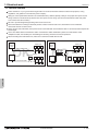
I.
Follow ordinance of your governmental organization for technical standard related to electrical equipment, wiring
regulations, and guidance of each electric power company.
Wiring for control (hereinafter referred to as transmission cable ) shall be (50mm[1-5/8in] or more) apart from power source
wiring so that it is not influenced by electric noise from power source wiring. (Do not insert transmission cable and power
source wire in the same conduit.)
Be sure to provide designated grounding work to heat source unit.
Give some allowance to wiring for electrical part box of indoor and heat source unit, because the box is sometimes
removed at the time of service work.
Never connect 100V, 208-230V, 575V power source to terminal block of transmission cable. If connected, electrical parts will
be damaged.
Use 2-core shield cable for transmission cable. If transmission cables of different systems are wired with the same
multiplecore cable, the resultant poor transmitting and receiving will cause erroneous operations.
When extending the transmission line, make sure to extend the shield cable as well.
Heat
source
unit
Indoor unit
OK
2-core shield cable
Heat
source
unit
Indoor unit
NO
Multiplecore cable
Remote
controller
BC controller
Remote
controller
BC controller
S.D. WR2 575V
2-core shield cable
SYSTEM DESIGN
4 - 340
1. Electrical work
DATA U10
1-2. Power supply for Indoor unit and Heat source unit
1-2-1. Electrical characteristics of Indoor unit
Symbols: MCA : Minimum Circuit Ampacity (=1.25xFLA) FLA : Full Load Amps
IFM :Indoor Fan Motor
Model
PLFY-P06NLMU-E
PLFY-P08NLMU-E
PLFY-P12NLMU-E
PLFY-P15NLMU-E
PLFY-P18NLMU-E
PLFY-P08NCMU-E
PLFY-P12NCMU-E
PLFY-P15NCMU-E
PLFY-P12NBMU-E
PLFY-P15NBMU-E
PLFY-P18NBMU-E
PLFY-P24NBMU-E
PLFY-P30NBMU-E
PLFY-P36NBMU-E
PMFY-P06NBMU-E
PMFY-P08NBMU-E
PMFY-P12NBMU-E
PMFY-P15NBMU-E
PEFY-P06NMSU-E
PEFY-P08NMSU-E
PEFY-P12NMSU-E
PEFY-P15NMSU-E
PEFY-P18NMSU-E
PEFY-P24NMSU-E
PEFY-P15NMHU-E2
PEFY-P18NMHU-E2
PEFY-P24NMHU-E2
PEFY-P27NMHU-E2
PEFY-P30NMHU-E2
PEFY-P36NMHU-E2
PEFY-P48NMHU-E2
PEFY-P54NMHU-E2
PEFY-P72NMHSU-E
PEFY-P96NMHSU-E
Output(kW)
0.015 / 0.015
0.015 / 0.015
0.015 / 0.015
0.015 / 0.015
0.020 / 0.020
0.015 / 0.015
0.020 / 0.020
0.020 / 0.020
0.050 / 0.050
0.050 / 0.050
0.050 / 0.050
0.050 / 0.050
0.050 / 0.050
0.120 / 0.120
FLA(A)
0.34 / 0.37
0.34 / 0.37
0.34 / 0.37
0.38 / 0.42
0.39 / 0.43
0.23 / 0.23
0.28 / 0.28
0.28 / 0.28
0.51 / 0.51
0.51 / 0.51
0.51 / 0.51
0.51 / 0.51
0.51 / 0.51
1.00 / 1.00
198 to 253V
0.25 / 0.25
0.25 / 0.25
0.26 / 0.26
0.33 / 0.33
0.028 / 0.028
0.028 / 0.028
0.028 / 0.028
0.028 / 0.028
0.20 / 0.20
0.20 / 0.20
0.21 / 0.21
0.26 / 0.26
188 to 253V
1.05 / 1.05
1.05 / 1.05
1.20 / 1.20
1.45 / 1.45
1.56 / 1.56
2.73 / 2.73
2.73 / 2.73
2.73 / 2.73
3.32 / 3.32
3.41 / 3.41
3.31 / 3.31
0.085 / 0.085
0.085 / 0.085
0.085 / 0.085
0.085 / 0.085
0.085 / 0.085
0.121 / 0.121
0.121 / 0.121
0.121 / 0.121
0.244 / 0.244
0.244 / 0.244
0.244 / 0.244
0.84 / 0.84
0.84 / 0.84
0.96 / 0.96
1.16 / 1.16
1.25 / 1.25
2.18 / 2.18
2.18 / 2.18
2.18 / 2.18
2.66 / 2.66
2.73 / 2.73
2.65 / 2.65
0.47 / 0.50
0.47 / 0.50
0.68 / 0.74
1.20 / 1.33
1.20 / 1.33
1.57 / 1.73
1.63 / 1.50
1.63 / 1.50
2.11 / 1.83
2.35 / 2.13
2.70 / 2.45
4.16 / 3.67
4.16 / 3.67
4.18 / 3.69
7.7
8.2
0.023 / 0.023
0.023 / 0.023
0.032 / 0.032
0.130 / 0.130
0.130 / 0.130
0.180 / 0.180
0.17
0.17
0.25
0.26
0.31
0.49
0.49
0.55
0.87
0.87
0.32 / 0.31
0.41 / 0.39
0.46 / 0.43
0.47 / 0.45
0.64 / 0.60
0.88 / 0.83
1.30 / 1.20
1.30 / 1.20
1.69 / 1.46
1.88 / 1.70
2.16 / 1.96
3.32 / 2.94
3.32 / 2.94
3.34 / 2.95
6.2
6.6
208 / 230V
198 to 253V
60Hz
60Hz
208 / 230V
208 / 230V
188 to 253V
60Hz
IFM
MCA(A)
0.43 / 0.47
0.43 / 0.47
0.43 / 0.47
0.48 / 0.53
0.49 / 0.54
0.29 / 0.29
0.35 / 0.35
0.35 / 0.35
0.64 / 0.64
0.64 / 0.64
0.64 / 0.64
0.64 / 0.64
0.64 / 0.64
1.25 / 1.25
188 to 253V
60Hz
Output : Fan motor rated output
208 / 230V
187 to 253V
SYSTEM DESIGN
4 - 341
S.D. WR2 575V
PEFY-P06NMAU-E3
PEFY-P08NMAU-E3
PEFY-P12NMAU-E3
PEFY-P15NMAU-E3
PEFY-P18NMAU-E3
PEFY-P24NMAU-E3
PEFY-P27NMAU-E3
PEFY-P30NMAU-E3
PEFY-P36NMAU-E3
PEFY-P48NMAU-E3
PEFY-P54NMAU-E3
Hz
Indoor Unit
Volts
Voltage range
1. Electrical work
DATA U10
Symbols: MCA : Minimum Circuit Ampacity (=1.25xFLA) FLA : Full Load Amps
IFM :Indoor Fan Motor
Model
PCFY-P15NKMU-E
PCFY-P24NKMU-E
PCFY-P30NKMU-E
PCFY-P36NKMU-E
PKFY-P06NBMU-E2
PKFY-P08NHMU-E2
PKFY-P12NHMU-E2
PKFY-P15NHMU-E2
PKFY-P18NHMU-E2
PKFY-P24NKMU-E2
PKFY-P30NKMU-E2
PFFY-P06NEMU-E
PFFY-P08NEMU-E
PFFY-P12NEMU-E
PFFY-P15NEMU-E
PFFY-P18NEMU-E
PFFY-P24NEMU-E
60Hz
60Hz
60Hz
60Hz
208 / 230V
208 / 230V
208 / 230V
208 / 230V
Output : Fan motor rated output
IFM
MCA(A)
0.44 / 0.44
0.52 / 0.52
1.22 / 1.22
1.22 / 1.22
Output(kW)
0.090 / 0.090
0.095 / 0.095
0.160 / 0.160
0.160 / 0.160
FLA(A)
0.35 / 0.35
0.41 / 0.41
0.97 / 0.97
0.97 / 0.97
198 to 253V
0.19 / 0.19
0.38 / 0.38
0.38 / 0.38
0.38 / 0.38
0.38 / 0.38
0.63 / 0.63
0.63 / 0.63
0.008 / 0.008
0.030 / 0.030
0.030 / 0.030
0.030 / 0.030
0.030 / 0.030
0.056 / 0.056
0.056 / 0.056
0.15 / 0.15
0.30 / 0.30
0.30 / 0.30
0.30 / 0.30
0.30 / 0.30
0.50 / 0.50
0.50 / 0.50
188 to 253V
0.32 / 0.34
0.32 / 0.34
0.34 / 0.38
0.40 / 0.44
0.48 / 0.53
0.59 / 0.64
0.015 / 0.015
0.015 / 0.015
0.018 / 0.018
0.030 / 0.030
0.035 / 0.035
0.063 / 0.063
0.25 / 0.27
0.25 / 0.27
0.27 / 0.30
0.32 / 0.35
0.38 / 0.42
0.47 / 0.51
188 to 253V
0.32 / 0.34
0.32 / 0.34
0.34 / 0.38
0.40 / 0.44
0.48 / 0.53
0.59 / 0.64
0.015 / 0.015
0.015 / 0.015
0.018 / 0.018
0.030 / 0.030
0.035 / 0.035
0.063 / 0.063
0.25 / 0.27
0.25 / 0.27
0.27 / 0.30
0.32 / 0.35
0.38 / 0.42
0.47 / 0.51
198 to 253V
S.D. WR2 575V
PFFY-P06NRMU-E
PFFY-P08NRMU-E
PFFY-P12NRMU-E
PFFY-P15NRMU-E
PFFY-P18NRMU-E
PFFY-P24NRMU-E
Hz
Indoor Unit
Volts
Voltage range
SYSTEM DESIGN
4 - 342
1. Electrical work
DATA U10
1-2-2. Electrical characteristics of Heat source unit at cooling mode
Symbols: MCA: Minimum Circuit Ampacity
SC: Starting Current
MOCP: Maximum Over Current Protection
PQRY-P-Z(S)KMU
Heat source unit
Model
Unit Combination
Hz
Volts
Voltage range MCA(A)
Compressor
Max.CKT.
BKR(A)
MOCP(A)
Output(kW)
SC(A)
PQRY-P72ZKMU-A
-
9
15
15
4.3
7
PQRY-P96ZKMU-A
-
11
15
18
6.0
7
PQRY-P120ZKMU-A
-
13
20
22
7.7
7
9
15
15
4.3
7
PQRY-P144ZSKMU-A
PQRY-P72ZKMU-A
PQRY-P72ZKMU-A
9
15
15
4.3
7
PQRY-P168ZSKMU-A
PQRY-P72ZKMU-A
9
15
15
4.3
7
PQRY-P192ZSKMU-A
PQRY-P96ZKMU-A
PQRY-P96ZKMU-A
11
15
18
6.0
7
PQRY-P216ZSKMU-A
PQRY-P96ZKMU-A
11
15
18
6.0
7
7
PQRY-P96ZKMU-A
PQRY-P240ZSKMU-A
60Hz
575V
518 to 633V
11
15
18
6.0
7
11
15
18
6.0
7
PQRY-P120ZKMU-A
13
20
22
7.7
PQRY-P120ZKMU-A
13
20
22
7.7
7
PQRY-P120ZKMU-A
13
20
22
7.7
7
S.D. WR2 575V
SYSTEM DESIGN
4 - 343
1. Electrical work
DATA U10
1-2-3. Electrical characteristics of BC controller
Symbols: MCA : Minimum Circuit Ampacity
FLA : Full Load Amps RLA : Rated Load Amps
Hz
Volts
60Hz
208 / 230V
Voltage range
198 to 253V
188 to 253V
MCA(A)
0.36 / 0.33
0.44 / 0.40
0.52 / 0.47
0.68 / 0.61
0.83 / 0.75
1.08 / 0.97
1.30 / 1.18
0.68 / 0.61
0.83 / 0.75
1.08 / 0.97
1.30 / 1.18
0.32 / 0.29
0.64 / 0.58
1.65 / 1.93
2.22 / 1.71
FLA(A)
15 / 15
15 / 15
15 / 15
15 / 15
15 / 15
15 / 15
15 / 15
15 / 15
15 / 15
15 / 15
15 / 15
15 / 15
15 / 15
15 / 15
15 / 15
RLA(A)
0.29 / 0.26
0.35 / 0.32
0.41 / 0.37
0.54 / 0.49
0.66 / 0.60
0.86 / 0.77
1.04 / 0.94
0.54 / 0.49
0.66 / 0.60
0.86 / 0.77
1.04 / 0.94
0.25 / 0.23
0.51 / 0.46
1.32 / 1.54
1.17 / 1.37
S.D. WR2 575V
Model
CMB-P104NU-G
CMB-P105NU-G
CMB-P106NU-G
CMB-P108NU-G
CMB-P1010NU-G
CMB-P1013NU-G
CMB-P1016NU-G
CMB-P108NU-GA
CMB-P1010NU-GA
CMB-P1013NU-GA
CMB-P1016NU-GA
CMB-P104NU-GB
CMB-P108NU-GB
CMB-P1016NU-HA
CMB-P1016NU-HB
SYSTEM DESIGN
4 - 344
1. Electrical work
DATA U10
1-3. Power cable specifications
Thickness of wire for main power supply, capacities of the switch and system impedance
Model
Heat source unit
Minimum wire thickness (mm2/AWG)
Main cable
Branch
Switch (A)
Breaker for current leakage
Ground
Capacity
Breaker for
Fuse
wiring (NFB)
15
PQRY-P72ZKMU-A
2.1/14
-
2.1/14
15A 30mA or 100mA 0.1sec. or less
15
15
PQRY-P96ZKMU-A
2.1/14
-
2.1/14
15A 30mA or 100mA 0.1sec. or less
15
15
15
PQRY-P120ZKMU-A
3.3/12
-
3.3/12
20A 30mA or 100mA 0.1sec. or less
20
20
20
F0 = 15 or less *1
2.1/14
2.1/14
2.1/14
15A current sensitivity *2
15
15
15
F0 = 20 or less *1
3.3/12
3.3/12
3.3/12
20A current sensitivity *2
20
20
20
F0 = 30 or less *1
5.3/10
5.3/10
5.3/10
30A current sensitivity *2
30
30
30
Total operating
current of
the indoor unit
*1 Please take the larger of F1 or F2 as the value for F0.
F1 = Total operating maximum curent of the indoor units × 1.2
F2 = {V1 × (Quantity of Type1)/C} + {V1 × (Quantity of Type2)/C} + {V1 × (Quantity of Type3)/C} + {V1 × (Quantity of Others)/C}
PLFY-NBMU, PMFY-NBMU, PEFY-NMSU, PCFY-NKMU,
PKFY-NHMU, PKFY-NKMU
Type2
PEFY-NMAU
Type3
PEFY-NMHSU
Others
V1
V2
18.6
2.4
38
1.6
13.8
4.8
0
0
Other indoor unit
C : Multiple of tripping current at tripping time 0.01s
Please pick up "C" from the tripping characteristic of the breaker.
<Example of "F2" calculation>
*Condition PEFY-NMSU × 4 + PEFY-NMAU × 1, C = 8 (refer to right sample chart)
6000
600
Tripping Time [s]
Indoor unit
Type1
SAMPLE
60
10
1
F2 = 18.6 × 4/8 + 38 × 1/8
= 14.05
0.1
16 A breaker (Tripping current = 8 × 16 A at 0.01s)
0.01
1
2
3 4
6 8 10
20
C
Rated Tripping current (x)
Sample chart
*2 Current sensitivity is calculated using the following formula.
G1 = (V2 × Quantity of Type1) + (V2 × Quantity of Type2) + (V2 × Quantity of Type3) + (V2 × Quantity of Others) + (V3 × Wire length [km])
Wire thickness
V3
30 or less
G1
30 mA 0.1sec or less
Current sensitivity
1.5 mm2
48
100 or less
100 mA 0.1sec or less
2.5 mm2
56
4.0 mm2
66
1. Use dedicated power supplies for the heat source unit and indoor unit. Ensure OC and OS are wired individually.
2. Bear in mind ambient conditions (ambient temperature,direct sunlight, rain water,etc.) when proceeding with the wiring and connections.
4. Specific wiring requirements should adhere to the wiring regulations of the region.
5. Power supply cords of parts of appliances for heat source use shall not be lighter than polychloroprene sheathed flexible cord (design 245 IEC57). For example, use wiring such as YZW.
6. A switch with at least 3 mm [1/8 in.] contact separation in each pole shall be provided by the Air Conditioner installer.
Be sure to use specified wires for connections and ensure no external force is imparted to terminal connections. If connections are not fixed firmly, heating or fire may result.
Be sure to use the appropriate type of overcurrent protection switch. Note that generated overcurrent may include some amount of direct current.
The breakers for current leakage should support Inverter circuit. (e.g. Mitsubishi Electric's NV-C series or equivalent). If no earth leakage breaker is installed, it may cause an electric shock.
Breakers for current leakage should combine using of switch.
Do not use anything other than a breaker with the correct capacity. Using a breaker of too large capacity may cause malfunction or fire.
If a large electric current flows due to malfunction or faulty wiring, earth-leakage breakers on the unit side and on the upstream side of the power supply system may both operate.
Depending on the importance of the system, separate the power supply system or take protective coordination of breakers.
SYSTEM DESIGN
4 - 345
S.D. WR2 575V
3. The wire size is the minimum value for metal conduit wiring. If the voltage drops, use a wire that is one rank thicker in diameter. Make sure the power-supply voltage does not drop more
than 10%. Make sure that the voltage imbalance between the phases is 2% or less.
1. Electrical work
DATA U10
1-4. Power supply examples
The local standards and/or regulations is applicable at a higher priority.
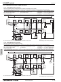
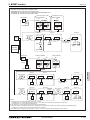
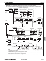
1-4-1. PQRY-P72, 96, 120ZKMU
Note:
1 The transmission cable is not-polarity double-wire.
2 Symbol
means a screw terminal for wiring.
3 The shield wire of transmission cable should be connected to the grounding terminal at
Heat source unit. All shield wire of M-Net transmission cable among Indoor units should be
connected to the S terminal at Indoor unit or all shield wire should be connected
together.
The broken line at the scheme means shield wire.
4 When the Heat source unit connected with system controller, power-supply to TB7 of the
heat source unit(s) is needed. The connector change from CN41 to CN40 at one of the
heat source units will enable the heat source unit to supply power to TB7, or an extra power
supply unit PAC-SC51KUA should be used. The transmission cable (above 1.25mm2,
shielded, CVVS/CPEVS/MVVS) among Heat source units and system controllers is called
central control transmission cable. The shield wire of the central control transmission
cable must be grounded at the Heat source unit whose CN41 is changed to CN40. When
the power supply unit PAC-SC51KUA is used, connect the shielded cable to the ground
terminal on the PAC-SC51KUA.
5 MA R/C transmission cable (0.3-1.25mm2) must be less than 200m in length, while ME
R/C transmission cable (0.3-1.25mm2) must be less than 10m in length. But transmission
cable to the ME R/C can be extend using a M-NET cable (>=1.25mm2) when the length
is counted in the M-Net length. Both Compact MA and ME R/C transmission cables size
0.75~1.25mm2 in thickness.
6 To wire PAC-YT53CRAU, use a wire with a diameter of 0.3mm2 [AWG 22].
7 MA remote controller and ME remote controller should not be grouped together.
8 If using 1 or 2 (main/sub) MA remote controller to control more than 1 Indoor unit, use MA
transmission cable to connect all the TB15 terminals of the Indoor units. It is called
"Grouping".
If using 1 or 2 (main/sub) ME remote controller control more than 1 indoor unit, set
address to Indoor unit and ME remote controller. For the method, refer to 2-4. "Address
setting".
9 Indoor board consumes power from TB3. The power balance should be considered
according to System Design 2-3 "System configuration restrictions".
10 If Transmission booster is needed, be sure to connect the shield wires to the both sides
to the booster.
11 The critical current for choosing power source equipment is approximate
1.4 times of total rated current of the Heat source unit(s) or Indoor unit(s).
12 When System controller (SC) is connected to the system, turn the SW2-1 on.
13 The phases of electricity power must be confirmed to be right used. Phase-reverse, or
phase-missing could break the controllers.
<In the case a system controller is connected.>
Note12
Central control
transmission cable
>=1.25mm2
Shield cable
(CVVS, CPEVS
MVVS)
SC
Connector
CN41 CN40 HU
Note4
Note4
To other HU
Breakers for
current leakage Switch
TB1
TB3 TB7
(L1,L2,L3) (M1,M2) (M1,M2)
Power supply
3-phase 3-wire
575V 60Hz
Note11,13
TB7
(S)
G
Note3
To *1 or *2
BC controller
*1
TB02
(M1,M2)
TB01
S L,N
(Shield)
(Using MA remote controller)
Connecting TB5 terminal.
G
Pull box
Breakers for
current leakage Switch
Power supply
1-phase
208-230V 60Hz
Note11
* Power supply
specifications vary with the
model of connected indoor
units or BC controller
Note8
TB5 TB2 TB15
(M1,M2) (L,N) (1,2)
S
IU
(Shield)
TB5 TB2 TB15
(M1,M2) (L,N) (1,2)
S
(Shield)
Breakers for
current leakage
Power supply
1-phase
208-230V 60Hz
TB5 TB2 TB15
(M1,M2) (L,N) (1,2)
S
(Shield)
Switch
TB1
(R,S) E
TB2 TB3
S
(Shield)
Indoor-heat source
transmission cable
>=1.25mm2
Shield cable
MA R/C cable
0.3-1.25mm2
<=200m
Note5
(Shield)
Transmission
booster
Note9
Note10
Note7
Note8
MA R/C
S
TB5 TB2 TB15
(M1,M2) (L,N) (1,2)
S
(Shield)
G
MA R/C
MA R/C
BC controller
*2
TB02
(M1,M2)
TB01
S L,N
(Shield)
S.D. WR2 575V
(Using ME remote controller)
Connecting TB5 terminal.
G
Pull box
Breakers for
current leakage Switch
Power supply
1-phase
208-230V 60Hz
Note11
* Power supply
specifications vary with the
model of connected indoor
units or BC controller
Note8
TB5 TB2 TB15
(M1,M2) (L,N) (1,2)
S
(Shield)
IU
TB5 TB2 TB15
(M1,M2) (L,N) (1,2)
S
(Shield)
Breakers for
current leakage
Power supply
1-phase
208-230V 60Hz
TB5 TB2 TB15
(M1,M2) (L,N) (1,2)
S
(Shield)
Switch
TB1
(R,S) E
TB2 TB3
(Shield)
Indoor-heat source
transmission cable
>=1.25mm2
Shield cable
ME R/C
Symbol
Model
BKC
OCP
Breaker capacity
Over-current protector
NFB
HU
IU
SC
Non-fuse breaker
Heat source unit
Indoor unit
System controller
MA R/C
MA remote controller
ME R/C
ME remote controller
PQRY-P72ZKMU
PQRY-P96ZKMU
PQRY-P120ZKMU
*1
*2
*3
*4
15 A 30 mA or 100 mA 0.1 sec. or less
15 A 30 mA or 100 mA 0.1 sec. or less
20 A 30 mA or 100 mA 0.1 sec. or less
S
(Shield)
Transmission
booster
Note9
Note10
Note7
Note8
ME R/C
Breakers for current leakage
*1, *2, *4
S
TB5 TB2 TB15
(M1,M2) (L,N) (1,2)
S
(Shield)
G
ME R/C cable
0.3~1.25mm2
<=10m
Note5
ME R/C
Switch
Switch*4
Minimum Wire thickness
BKC
<A>
OCP*3, *4
<A>
(NFB)
<A>
Power wire
<mm2/AWG>
G wire
<mm2/AWG>
15
15
20
15
15
20
15
15
20
2.1/14
2.1/14
3.3/12
2.1/14
2.1/14
3.3/12
The breakers for current leakage should support Inverter circuit. (e.g. Mitsubishi Electric's NV-C series or equivalent).
Breakers for current leakage should combine using of switch.
It shows data for B-type fuse of the breaker for current leakage.
If a large electric current flows due to malfunction or faulty wiring, earth-leakage breakers on the unit side and on the centralized controller side
may both operate.
Depending on the importance of the system, separate the power supply system or take protective coordination of breakers.
SYSTEM DESIGN
4 - 346
1. Electrical work
DATA U10
The local standards and/or regulations is applicable at a higher priority.
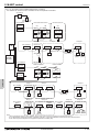
1-4-2. PQRY-P144, 168, 192, 216, 240ZSKMU
<In the case a system controller is connected.>
Note12
Note:
1 The transmission cable is not-polarity double-wire.
2 Symbol
means a screw terminal for wiring.
3 The shield wire of transmission cable should be connected to the grounding terminal at
Heat source unit. All shield wire of M-Net transmission cable among Indoor units should be
connected to the S terminal at Indoor unit or all shield wire should be connected
together.
The broken line at the scheme means shield wire.
4 When the Heat source unit connected with system controller, power-supply to TB7 of the
heat source unit(s) is needed. The connector change from CN41 to CN40 at one of the
heat source units will enable the heat source unit to supply power to TB7, or an extra power
supply unit PAC-SC51KUA should be used. The transmission cable (above 1.25mm2,
shielded, CVVS/CPEVS/MVVS) among Heat source units and system controllers is called
central control transmission cable. The shield wire of the central control transmission
cable must be grounded at the Heat source unit whose CN41 is changed to CN40. When
the power supply unit PAC-SC51KUA is used, connect the shielded cable to the ground
terminal on the PAC-SC51KUA.
5 MA R/C transmission cable (0.3-1.25mm2) must be less than 200m in length, while ME
R/C transmission cable (0.3-1.25mm2) must be less than 10m in length. But transmission
cable to the ME R/C can be extend using a M-NET cable (>=1.25mm2) when the length
TB7 is counted in the M-Net length. Both Compact MA and ME R/C transmission cables size
(S) 0.75~1.25mm2 in thickness.
6 To wire PAC-YT53CRAU, use a wire with a diameter of 0.3mm2 [AWG 22].
7 MA remote controller and ME remote controller should not be grouped together.
8 If using 1 or 2 (main/sub) MA remote controller to control more than 1 Indoor unit, use MA
transmission cable to connect all the TB15 terminals of the Indoor units. It is called
"Grouping".
If using 1 or 2 (main/sub) ME remote controller control more than 1 indoor unit, set
address to Indoor unit and ME remote controller. For the method, refer to 2-4. "Address
setting".
9 Indoor board consumes power from TB3. The power balance should be considered
according to System Design 2-3 "System configuration restrictions".
10 If Transmission booster is needed, be sure to connect the shield wires to the both sides
to the booster.
11 The critical current for choosing power source equipment is approximate
1.4 times of total rated current of the Heat source unit(s) or Indoor unit(s).
. on.
12 When System controller (SC) is connected to the system, turn the SW2-1
13 The phases of electricity power must be confirmed to be right used. Phase-reverse, or
phase-missing could break the controllers.
Central control
transmission cable
>=1.25mm2
Shield cable
(CVVS, CPEVS
MVVS)
SC
Connector
CN41 CN40
Note4
Note4
HU
HU
To other HU
Breakers for
current leakage Switch
Power supply
3-phase 3-wire
575V 60Hz
Note11,13
TB1
TB1
TB3 TB7
(L1,L2,L3) (M1,M2) (M1,M2)
TB7
(S)
TB3
TB7
(M1,M2) (M1,M2)
Breakers for
(L1,L2,L3)
current leakage Switch
Power supply
3-phase 3-wire
575V 60Hz
Note11,13
G
G
Note3
Note3
To *1 or *2
BC controller(Main)
BC controller(Sub)
TB02
(M1,M2)
*1
TB01
S L,N
(Shield)
(Using MA remote controller)
Connecting TB5 terminal.
TB02
(M1,M2)
G
Breakers for
current leakage Switch
TB01
S L,N
G
Pull box
Power supply
1-phase
208-230V 60Hz
Note11
* Power supply
specifications vary with the
model of connected indoor
units or BC controller
Note8
TB5 TB2 TB15
(M1,M2) (L,N) (1,2)
S
(Shield)
IU
TB5 TB2 TB15
(M1,M2) (L,N) (1,2)
S
(Shield)
TB5 TB2 TB15
(M1,M2) (L,N) (1,2)
S
(Shield)
Breakers for
Power supply current leakage Switch
1-phase
208-230V 60Hz
TB1
(R,S) E
TB2 TB3
(Shield)
Indoor-heat source
transmission cable
>=1.25mm2
Shield cable
TB02
(M1,M2)
(Using ME remote controller)
Connecting TB5 terminal.
TB01
S L,N
MA R/C
BC controller(Sub)
TB02
(M1,M2)
G
TB01
S L,N
G
(Shield)
Pull box
Breakers for
current leakage Switch
Note8
TB5 TB2 TB15
(M1,M2) (L,N) (1,2)
S
(Shield)
IU
TB5 TB2 TB15
(M1,M2) (L,N) (1,2)
S
(Shield)
TB5 TB2 TB15
(M1,M2) (L,N) (1,2)
S
(Shield)
Breakers for
Power supply current leakage Switch
1-phase
208-230V 60Hz
TB1
(R,S) E
TB2 TB3
(Shield)
Indoor-heat source
transmission cable
>=1.25mm2
Shield cable
ME R/C
Model
Symbol
BKC
OCP
Breaker capacity
Over-current protector
NFB
HU
IU
SC
Non-fuse breaker
Heat source unit
Indoor unit
System controller
MA R/C
MA remote controller
ME R/C
ME remote controller
PQRY-P72ZKMU
PQRY-P96ZKMU
PQRY-P120ZKMU
*1
*2
*3
*4
S
S
TB5 TB2 TB15
(M1,M2) (L,N) (1,2)
S
(Shield)
G
(Shield)
Transmission
booster
Note9
Note10
Note7
Note8
ME R/C
S.D. WR2 575V
Power supply
1-phase
208-230V 60Hz
Note11
* Power supply
specifications vary with the
model of connected indoor
units or BC controller
MA R/C cable
0.3-1.25mm2
<=200m
Note5
(Shield)
MA R/C
BC controller(Main)
*2
S
Transmission
booster
Note9
Note10
Note7
Note8
MA R/C
S
TB5 TB2 TB15
(M1,M2) (L,N) (1,2)
S
(Shield)
G
ME R/C cable
0.3~1.25mm2
<=10m
Note5
ME R/C
Breakers for current leakage
*1, *2, *4
15 A 30 mA or 100 mA 0.1 sec. or less
15 A 30 mA or 100 mA 0.1 sec. or less
20 A 30 mA or 100 mA 0.1 sec. or less
Switch
Switch*4
Minimum Wire thickness
BKC
<A>
OCP*3, *4
<A>
(NFB)
<A>
Power wire
<mm2/AWG>
G wire
<mm2/AWG>
15
15
20
15
15
20
15
15
20
2.1/14
2.1/14
3.3/12
2.1/14
2.1/14
3.3/12
The breakers for current leakage should support Inverter circuit. (e.g. Mitsubishi Electric's NV-C series or equivalent).
Breakers for current leakage should combine using of switch.
It shows data for B-type fuse of the breaker for current leakage.
If a large electric current flows due to malfunction or faulty wiring, earth-leakage breakers on the unit side and on the centralized controller side
may both operate.
Depending on the importance of the system, separate the power supply system or take protective coordination of breakers.
SYSTEM DESIGN
4 - 347
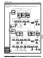
2. M-NET control
DATA U10
2-1. Transmission cable length limitation
2. M-NET control
2-1-1. Using MA Remote controller
MA remote controller refers to Simple MA remote controller and wireless remote controller.
Long transmission cable causes voltage down, therefore, the length limitation should be obeyed to secure proper transmission.
Max. length via Heat source (M-NET cable) L1+L2+L3+L4, L1+L2+L6+L7, L3+L4+L6+L7 <=500m[1640ft.] 1.25mm2 [AWG16] or thicker
Max. length to Heat source (M-NET cable) L1+L8, L3+L4, L6, L2+L6+L8, L7
<=200m[656ft.] 1.25mm2 [AWG16] or thicker
Max. length from MA to Indoor
a1+a2, a1+a2+a3+a4
<=200m[656ft.] 0.3-1.25 mm2 [AWG22-16]
24VDC to AG-150A-A
n
<=50m[164ft.]
0.75-2.0 mm2 [AWG18-14]
L8
L1
Group1
BC(Main)
OC
OS
(52)
(51)
(53)
TB3
M1M2
TB3
M1M2
TB02
M1M2 S
Group3
IC
(04)
(01)
TB5
M1M2 S
Group5
BC(Sub)
IC
TB15
1 2
TB5
M1M2 S
(55)
TB15
1 2
IC
IC
(05)
TB02
M1M2 S
TB5
M1M2 S
(06)
TB15
1 2
TB5
M1M2 S
TB15
1 2
a2
TB7
M1M2 S
L2
MA
(54 )
L4
BC(Main)
IC
IC
BC(Sub)
IC
(56)
(02)
(03)
(57)
(07)
TB7
TB3
M1M2
TB5
M1M2 S
TB02
M1M2 S
TB5 TB 15
M1M2 S 1 2
TB15
1 2
TB02
M1M2 S
TB5
M1M2 S
TB15
1 2
V+V-FG
AG-150A-A
A B S
A B
A B
MA
MA
n
L7
A B S
a1
Power Supply Unit
PAC-SC51KUA
a4
L6
M1 M2 S
MA
L3
OC
a3
A B
a2
A B
Shielded wire
a2
a1
a1
TB7
M1M2 S
V+V-FG
NOTE
Do not daisy-chain remote controllers.
OC, OS: Heat source unit controller; IC: Indoor unit controller; ME: ME remote controller
L1
L8
Group3
IC
(01)
(51)
(53)
TB3
M1M2
TB02
M1M2 S
TB7
M1M2 S
TB7
M1M2 S
BC(Sub)
(04)
TB5
M1M2 S
(55)
TB5
M1M2 S
TB02
M1M2 S
L2
Shielded wire
(05)
TB7
TB3
M1M2
A B
A B
A B
(105)
(155)
ME
ME
ME
L4
BC(Main)
IC
IC
BC(Sub)
IC
(56)
(02)
(03)
(57)
(07)
TB02
M1M2 S
TB5
M1M2 S
TB5
M1M2 S
TB5
M1M2 S
TB02
M1M2 S
TB5
M1M2 S
L6
L5
M1 M2 S
(06)
TB5
M1M2 S
(101)
L3
OC
(54 )
IC
IC
e2
(52)
TB3
M1M2
Group5
IC
e3
Group1
BC(Main)
OC
OS
A B S
e4
Power Supply Uni t
PAC-SC51KUA
V+V-FG
A B
n
(103)
L7
S.D. WR2 575V
2-1-2. Using ME Remote controller
ME remote controller refers to Smart ME Controller.
Long transmission cable causes voltage down, therefore, the length limitation should be obeyed to secure proper transmission.
Max. length via Heat source (M-NET cable) L1+L2+L3+L4, L1+L2+L6+L7,L1+L2+L3+L5, L3+L4+L6+L7 <=500m[1640ft.] 1.25mm2 [AWG16] or thicker
Max. length to Heat source (M-NET cable)
L1+L8, L3+L4, L6, L2+L6+L8, L7, L3+L5
<=200m[656ft.] 1.25mm2 [AWG16] or thicker
Max. length from ME to Indoor
e1, e2+e3, e4
<=10m[32ft.]*1
0.3-1.25 mm2 [AWG22-16] *1
24VDC to AG-150A-A
n
<=50m[164ft.]
0.75-2.0 mm2 [AWG18-14]
2
*1. If the length from ME to Indoor exceed 10m, use 1.25 mm [AWG16] shielded cable, but the total length should be counted into Max. length via Heat source.
AG-150A-A
A B S
ME
V+V-FG
OC, OS: Heat source unit controller; IC: Indoor unit controller; ME: ME remote controller
SYSTEM DESIGN
NOTE
Do not daisy-chain remote controllers.
4 - 348
2. M-NET control
DATA U10
2-2. Transmission cable specifications
Transmission cables (Li)
Type of cable
Cable size
Remarks
ME Remote controller cables
Shielding wire (2-core)
CVVS, CPEVS or MVVS
More than 1.25
[AWG16]
0.3 1.25
2
[AWG22 16]*2
When 10m [32ft] is exceeded, use cables with
the same specification as transmission cables.
—
MA Remote controller cables
Sheathed 2-core cable (unshielded)
CVV
mm2
*1 To wire PAC-YT53CRAU, use a wire with a diameter of 0.3
[AWG22]
*2 The use of cables 0.75 mm2 [AWG18] or greater is recommended for easy
handling.
0.3 1.25
2
[AWG22 16] *1 *2
Max length : 200m [656ft]
CVVS, MVVS: PVC insulated PVC jacketed shielded control cable
CPEVS: PE insulated PVC jacketed shielded communication cable
CVV: PV insulated PVC sheathed control cable
S.D. WR2 575V
SYSTEM DESIGN
4 - 349
2. M-NET control
DATA U10
2-3. System configuration restrictions
2-3-1. Common restrictions for the CITY MULTI system
For each Heat source unit, the maximum connectable quantity of Indoor unit is specified at its Specifications table.
A) 1 Group of Indoor units can have 1-16 Indoor units;
B) Maximum 2 remote controllers for 1 Group;
*MA/ME remote controllers cannot be present together in 1group.
*To wire PAC-YT53CRAU, use a wire with a diameter of 0.3 mm2 [AWG22]
C) 1 LOSSNAY unit can interlock maximum 16 Indoor units; 1 Indoor unit can interlock only 1 LOSSNAY unit.
D) Maximum 3 System controllers are connectable when connecting to TB3 of the Heat source unit.
E) Maximum 6 System controllers are connectable when connecting to TB7 of the Heat source unit, if the transmission
power is supplied by the Heat source unit.
F) 4 System controllers or more are connectable when connecting to TB7 of the Heat source unit, if the transmission
power is supplied by the power supply unit PAC-SC51KUA. Details refer to 2-3-3-C.
*System controller connected as described in D) and E) would have a risk that the failure of connected Heat source
unit would stop power supply to the System controller
2-3-2. Ensuring proper communication power for M-NET
In order to ensure proper communication among Heat source unit, Indoor unit, LOSSNAY and Controllers, the transmission
power situation for the M-NET should be observed. In some cases, Transmission booster should be used. Taking the power
consumption index of Indoor unit sized P06-P54 as 1, the equivalent power consumption index and supply capability index
of others are listed at Table 2-3-1 and Table 2-3-2.
Table 2-3-1 The equivalent power consumption
BC
Indoor unit
PWFY
LOSSNAY controller
CMB
Sized
PEFY-AF1200 LGH-RX-E
P36NMU-E-BU P36NMU-E-AU P72NMU-E-AU
Sized
P06-P54 P72, 96 CFMR
1
7
2
0
2
6
1
ME Remote controller/Adapter
MA RC.
PAC-YT53CRAU
PAR-FA32MA
PZ-41SLB
PZ-60DR-E
5
PZ-52SF
PAC-YG60MCA
PAC-YG66DCA
PAC-YG63MCA
0
1/4
PAR-U01MEDU
PAC-IF01AHC-J
1/2
Centralized
ON/OFF
M-NET
Heat source unit
MN Converter
controller
Remote controller
Interface/Converter
AG-150A-A TC-24B GB-24A LMAP04U-E PAC-YT40ANRA CMS-MNF-B CMS-MNG-E MAC-333
TB7 power consumption
EB-50GU-A
BAC-HD150
PAC-SF83MA-E
1/2
4
3
0
1
1/2
0
2
0
*RC: Remote Controller
Table 2-3-2 The equivalent power supply
Transmission Booster
Power supply unit
Expansion controller
PAC-SF46EPA
25
PAC-SC51KUA
5
PAC-YG50ECA
6
Heat source unit
Heat source unit
Connector TB3 and TB7 total *
32
Connector TB7 only
6
BM ADAPTER System Controller
BAC-HD150
6
GB-50ADA-A
6
S.D. WR2 575V
*If PAC-SC51KUA is used to supply power at TB7 side, no power supply need from Heat source unit at TB7, Connector TB3 itself will therefore have 32.
With the equivalent power consumption values in Table 2-3-1 and Table 2-3-2, PAC-SF46EPA can be designed into the airconditioner system to ensure proper system communication according to 2-3-2-A, B, C.
2-3-2-A) Firstly, count from TB3 at TB3 side the total quantity of Indoor units, ME remote controller, and System controllers.
If the total quantity reaches 40, a PAC-SF46EPA should be set. In this case, Indoor units sized P72 and 96 are
counted as 2 indoor units, but MA remote controller(s) and PZ-41SLB are NOT counted.
2-3-2-B) Secondly, count from TB7 side to TB3 side the total transmission power consumption index. If the total power consumption
reaches 32, a PAC-SF46EPA should be set. Yet, if a PAC-SC51KUA or another controller with a built-in power supply,
such as PAC-YG50ECA, is used to supply power at TB7 side, count from index TB3 side only.
2-3-2-C) Thirdly, count from TB7 at TB7 side the total transmission power consumption index, If the total power consumption reaches
6, a PAC-SF46EPA should be set.
System example
TB7
TB3
UP
TRANSMISSION BOOSTER
MODEL
PAC-SF46EPA
POWER RATING
220-240V:0.7A ~/N
50
WEIGHT
3.4kg
MADE IN JAPAN
01
Transmission
booster
(No.1)
02
ME remote
controller
TB7
TB3
Heat source unit
ME remote
controller
N1
N2
Within N2, conditions 1,2 should be followed.
1.The total quantity of Indoor units and ME remote controller
should not exceed 40.
*Indoor units sized P72 and 96 are counted as 2 units.
2.The total equivalent transmission power consumption
should not exceed 25.
Transmission booster (No.1) should be used,
if the total quantity of Indoor units and ME remote controllers
reaches 40, (Indoor units sized P72 and 96 are counted as 2);
or if the total equivalent transmission power consumption reaches 32.
UP
TRANSMISSION BOOSTER
MODEL
PAC-SF46EPA
POWER RATING
220-240V:0.7A ~/N
50
WEIGHT
3.4kg
MADE IN JAPAN
M-NET
24VDC
Power supply unit
PAC-SC51KUA
Transmission
booster
PAC-SF46EPA
(No.2)
LOSSNAY
unit
CENTRALIZED CONTROLLER AG-150A
Centralized controller
(AG-150A-A)
LOSSNAY
remote controller
LOSSNAY
unit
LOSSNAY
remote controller
N3
N4
Transmission booster (No.2) should be used,
if the total equivalent transmission power consumption reaches 5.
Within N4, the total equivalent transmission
power consumption should not exceed 25.
SYSTEM DESIGN
4 - 350
2. M-NET control
DATA U10
2-3-3. Ensuring proper power supply to System controller
The power to System controller (excluding LM-AP) is supplied via M-NET transmission line. M-NET transmission line at
TB7 side is called Central control transmission line while one at TB3 side is called Indoor-Heat source transmission line.
There are 3 ways to supply power to the System controller .
A) Connecting to TB3 of the Heat source unit and receiving power from the Heat source unit.
B) Connecting to TB7 of the Heat source unit and receiving power from the Heat source unit.
C) Connecting to TB7 of the Heat source unit but receiving power from power supply unit PAC-SC51KUA.
2-3-3-A. When connecting to TB3 of the Heat source unit and receiving power from the Heat source unit.
Maximum 3 System controllers can be connected to TB3.
Fig. 2-3-3-A
If there is more than 1 Heat source unit, it is necessary to
System controller
M-NET transmission lines
(excluding LM-AP)
(Indoor-Heat source transmission lines)
Heat source unit
replace power supply switch connector CN41 with CN40
Group
Group
on one Heat source unit.
TB3
TB7
Replacement of
CN41 with CN40
Indoor unit
M-NET transmission lines
(transmission lines
for central controller)
MA remote controller
Heat source unit
Group
Group
TB3
TB7
Use CN41
as it is.
Indoor unit
ME remote controller
System
controller
Maximum 3 System controllers can be connected to TB3.
2-3-3-B. When connecting to TB7 of the Heat source unit and receiving power from the Heat source unit.
Maximum 6 System controllers can be connected to TB7
and receiving power from the Heat source unit.
Fig. 2-3-3-B
M-NET transmission lines
(Indoor-Heat source transmission lines)
It is necessary to replace power supply switch connector
Heat source unit
Group
Group
CN41 with CN40 on one Heat source unit.
TB3
TB7
Replacement of
CN41 with CN40
Indoor unit
M-NET transmission lines
(transmission lines
for central controller)
MA remote controller
Heat source unit
Group
Group
TB3
TB7
Use CN41
as it is.
Indoor unit
ME remote controller
System
controller
Maximum 6 System controllers can be connected to TB7.
S.D. WR2 575V
2-3-3-C. When connecting to TB7 of the Heat source unit but receiving power from PAC-SC51KUA.
When using PAC-SC51KUA to supply transmission power,
the power supply connector CN41 on the Heat source units
should be kept as it is. It is also a factory setting.
1 PAC-SC51KUA supports maximum 1 AG-150A-A or 1
EB-50GU-A unit due to the limited power DC 24V at its
TB3.
However, 1 PAC-SC51KUA supplies transmission power at
its TB2 equal to 5 Indoor units, which is referable at Table
2-3-2.
If PZ-52SF, System controller, ON/OFF controller
connected to TB7 consume transmission power more than
5 (Indoor units), Transmission booster PAC-SF46EPA is
needed. PAC-SF46EPA supplies transmission power equal
to 25 Indoor units.
Fig. 2-3-3-D
M-NET transmission lines
(Indoor-Heat source transmission lines)
Heat source unit
Group
Group
TB3
TB7
Use CN41
as it is.
Indoor unit
M-NET transmission lines
(transmission lines
for central controller)
MA remote controller
Heat source unit
Group
Group
TB3
TB7
Use CN41
as it is.
PAC-SC51KUA
Indoor unit
ME remote controller
System
controller
CAUTION
AG-150A-A/EB-50GU-A*1 are recommended to connect to TB7 because it performs back-up to a number of data.
In an air conditioner system has more than 1 Heat source units, AG-150A-A/EB-50GU-A receiving transmission power at TB3 or TB7 on one of the Heat
source units would have a risk that the connected Heat source unit failure would stop power supply to AG-150A-A/EB-50GU-A, and disrupt the whole system.
When applying apportioned electric power function, AG-150A-A/EB-50GU-A are necessary to connected to TB7 and has its own power supply unit
PAC-SC51KUA.
Note: Power supply unit PAC-SC51KUA is for AG-150A-A/EB-50GU-A.
*1: AG-150A-A is an example model of system controllers.
SYSTEM DESIGN
4 - 351
2. M-NET control
DATA U10
2-3-4. Power supply to LM-AP
1-phase 208-230V AC power supply is needed.
The power supply unit PAC-SC51KUA is not necessary when connecting only the LM-AP. Yet, make sure to change
the power supply changeover connector CN41 to CN40 on the LM-AP.
2-3-5. Power supply to expansion controller
1-phase 100-240VAC power supply is needed.
The power supply unit PAC-SC51KUA is not necessary.
The expansion controller supplies power through TB3, which equals 6 indoor units. (refer to Table 2-3-2)
2-3-6. Power supply to BM ADAPTER
1-phase 100-240VAC power supply is needed.
The power supply unit PAC-SC51KUA is not necessary when only BM ADAPTER is connected.
Yet, make sure to move the power jumper from CN41 to CN40 on the BM ADAPTER.
2-3-7. Power supply to GB-50ADA-A
S.D. WR2 575V
1-phase 100-240VAC power supply is needed.
The power supply unit PAC-SC51KUA is not necessary.
GB-50ADA-A supplies power through TB3, which equals 6 indoor units. (refer to Table 2-3-2)
SYSTEM DESIGN
4 - 352
2. M-NET control
DATA U10
2-4. Address setting
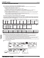
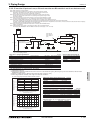
2-4-1. Switch operation
01
9
2 3
7 8
01
7 8
9
2 3
D
BC E
Unit address No. setting
45 6
F 0 12
3456
789A
Address No. of heat source unit, indoor unit and ME remote controller.
The address No. is set at the address setting board.
In the case of WR2 system, it is necessary to set the same No. at the
branch No. switch of indoor unit as that of the BC controller
connected. (When connecting two or more branches, use the lowest
branch No.)
Caution for switch operations
Rotary switch
Branch
No. setting
45 6
In order to constitute CITY MULTI in a complete system, switch
operation for setting the unit address No. and connection No. is
required.
Be sure to shut off power source before switch setting. If operated with power source on, switch can
not operate properly.
No units with identical unit address shall exist in one whole air conditioner system. If set erroneously,
the system can not operate.
MA remote controller
When connecting only one remote controller to one group, it is always the main remote controller.
When connecting two remote controllers to one group, set one remote controller as the main remote controller
and the other as the sub remote controller.
The factory setting is Main .
PAC-YT53CRAU
Setting the dip switches
There are switches on the back of the top case. Remote controller Main/Sub and other function settings are performed
using these switches. Ordinarily, only change the Main/Sub setting of SW1.
(The factory settings are ON for SW1, 3, and 4 and OFF for SW2.)
SW No
4
Indoor temperature
display
1
2
Comment
ON
OFF
Main
Sub
Celsius
Fahrenheit
When the temperature is displayed in [Fahrenheit], set to “OFF”.
Yes
No
When you do not want to display “Cooling” and “Heating” in the
AUTO mode, set to “OFF”.
Yes
No
When you do not want to display the indoor temperature,
set to “OFF”.
Set one of the two remote controllers at one group to “ON”.
SYSTEM DESIGN
4 - 353
S.D. WR2 575V
3
SW contents Main
Remote controller
Main/Sub setting
Temperature display
units setting
Cooling/heating
display in AUTO mode
2. M-NET control
DATA U10
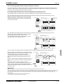
2-4-2. Rule of setting address
Unit
Address setting
Example
Note
7 8
9 0 1
4 5 6
4 5 6
10
1
7 8
7 8
7 8
7 8
7 8
9 0 1
4 5 6
4 5 6
10
1
01
9
0
0
0
100
10
1
0
0
0
100
10
1
0
0
0
100
10
1
9 0 1
9 0 1
The smallest address of indoor unit in the group + 100
The address of main remote controller + 50
The address automatically becomes "200" if it is set
as "00"
The smallest group No. to be managed + 200
The smallest group No. to be managed is changeable.
Settings are made on the initial screen of AG-150A-A.
Settings are made with setting tool of BM ADAPTER.
2 3
2 3
4 5 6
4 5 6
Fixed
7 8
1
7 8
45 6
45 6
10
2
Lowest address within the indoor units connected to
the BC controller (Sub) plus 50.
01
7 8
7 8
7 8
7 8
7 8
9
100
000, 201 ~ 250
201 ~ 250
1
45 6
000, 201 ~ 250
45 6
PAC-YG50ECA
01
10
Please reset one of them to an address between 51
and 99 when two addresses overlap.
The address automatically becomes "100" if it is set
as "01~ 50"
The place of "100" is fixed to "1"
2 3
000, 201 ~ 250
9
2 3
AG-150A-A
GB-50ADA-A
GB-24A
EB-50GU-A
01
45 6
01
7 8
7 8
45 6
45 6
1
2 3
Fixed
2 3
1
01
10
9
000, 201 ~ 250
9
2 3
Local remote controller
9 0 1
Fixed
2 3
System controller
4 5 6
4 5 6
1
The smallest address of indoor unit in same refrigerant
system + 50
Assign sequential address numbers to the heat source
units in one refrigerant circuit system. OC and OS are
automatically detected. (Note 2)
Please reset one of them to an address between 51
and 99 when two addresses overlap.
The address automatically becomes "100" if it is set
as "01~ 50"
The address of heat source unit + 1
2 3
151 ~ 199, 200
1
9
S.D. WR2 575V
4 5 6
4 5 6
10
2 3
ME, LOSSNAY
Remote controller
(Sub)
LMAP04U-E
9 0 1
0
9 1
101 ~ 150
BAC-HD150
9 0 1
2 3
52 ~ 99, 100
2 3
52 ~ 99, 100
ME, LOSSNAY
Remote controller
(Main)
ON/OFF remote
controller
1
2 3
BC controller
(Sub)
10
2 3
BC controller
(Main)
9 0 1
2 3
Heat source unit
7 8
9 0 1
51 ~ 99, 100
(Note1)
2 3
01 ~ 50
2 3
7 8
9 0 1
Indoor unit
Use the most recent address within the same group of
indoor units. Make the indoor units address connected
to the BC controller (Sub) larger than the indoor units
address connected to the BC controller (Main).
If applicable, set the sub BC controllers in an PQRY
system in the following order:
(1) Indoor unit to be connected to the BC controller (Main)
(2) Indoor unit to be connected to the BC controller (No.1 Sub)
(3) Indoor unit to be connected to the BC controller (No.2 Sub)
Set the address so that (1)<(2)<(3)
10
1
Note1: To set the address to "100", set it to "50"
Note2: Heat source units OC and OS in one refrigerant circuit system are automatically detected.
OC and OS are ranked in descending order of capacity. If units are the same capacity, they are ranked in ascending
order of their address.
SYSTEM DESIGN
4 - 354
2. M-NET control
DATA U10
2-4-3. System examples
Factory setting
Original switch setting of the heat sources, indoors, controllers, LM-AP, and BM ADAPTER at shipment is as follows.
• Heat source unit
: Address: 00, CN41: ON (Jumper), DipSW5-1: OFF
• Indoor unit
: Address: 00
• BC controller
: Address: 00
• ME remote controller : Address: 101
• LM-AP
: Address: 247, CN41: ON (Jumper), DipSW1-2: OFF
: Address: 000, CN41: ON (Jumper)
• BM ADAPTER
Setting at the site
• DipSW5-1(Heat source) : When the System Controller is used, all the Dip SW5-1 at the heat source units should be
set to "ON". * Dip SW5-1 remains OFF when only LM-AP is used.
• DipSW1-2(LM-AP)
: When the LM-AP is used together with System Controller, DipSW1-2 at the LM-AP
should be set to "ON".
• CN40/CN41
: Change jumper from CN41 to CN 40 at heat source control board will activate central
transmission power supply to TB7;
(Change jumper at only one heat source unit when activating the transmission power supply
without using a power supply unit.)
Change jumper from CN41 to CN 40 at LM-AP will activate transmission power supply to LM-AP
itself;
Power supply unit is recommended to use for a system having more than 1 heat source unit,
because the central transmission power supply from TB7 of one of heat source units is risking
that the heat source unit failure may let down the whole central control system.
2-4-3-1. MA remote controller, Single-refrigerant-system, No System Controller
<Two heat source units>
PQRY-P-ZSKMU
OC
OS
00
CN40
CN41
00
CN40
DipSW5-1
OFF
TB3
<One heat source units>
PQRY-P-ZKMU
OC
CN41
DipSW5-1
OFF
TB3
00
CN40
CN41
DipSW5-1
OFF
TB3
BC controller
Group 3
Group 4
Indoor unit
00
TB02
Group 2
S.D. WR2 575V
Group 1
00
TB5
SRU
00
TB15
TB5
00
TB15
TB5
00
TB15
TB5
00
TB15
TB5
TB15
1*
MA R/C
MA R/C
MA R/C MA R/C
(Main)
(Sub)
1*
Wireless R/C
*1 For Wireless R/C and Signal receiver unit (SRU), channel 1, 2 and 3 are selectable and should be set to same channel.
NOTE:
1. Heat source units OC and OS in one refrigerant circuit system are automatically detected.
OC and OS are ranked in descending order of capacity. If units are the same capacity, they are ranked in ascending order
of their address.
2. No address setting is needed.
3. For a system having more than 32 indoor unit (P06-P54), confirm the need of Booster at 2-3 "System configuration
restrictions".
4. Indoor units should be set with a branch number.
5. Address setting is required if a sub BC controller is connected.
SYSTEM DESIGN
4 - 355
2. M-NET control
DATA U10
2-4-3-2. MA remote controller, Single-refrigerant-system, System Controller
<Two heat source units>
PQRY-P-ZSKMU
OC
OS
51
CN40
CN41
52
CN40
DipSW5-1
ON
TB3
<One heat source units>
PQRY-P-ZKMU
OC
CN41
DipSW5-1
ON
TB3
51
CN40
CN41
DipSW5-1
ON
TB3
Group 1
BC controller
01
TB5
02
TB15
201
SC
Group 3
Group 4
Indoor unit
53
TB02
Group 2
03
TB5
SRU
TB15
TB5
04
TB15
TB5
05
TB15
TB5
TB15
1*
MA R/C
MA R/C
MA R/C MA R/C
(Main)
(Sub)
1*
Wireless R/C
*1 For Wireless R/C and Signal receiver unit (SRU), channel 1, 2 and 3 are selectable and should be set to same channel
.
S.D. WR2 575V
*SC can be connected to TB3 side or TB7 side;
Should SC connected to TB7 side, change Jumper from CN41 to CN40 at the Heat source unit module so as to supply power to the
SC.
NOTE:
1. Heat source units OC and OS in one refrigerant circuit system are automatically detected.
OC and OS are ranked in descending order of capacity. If units are the same capacity, they are ranked in ascending order
of their address.
2. Address should be set to Indoor units and central controller.
3. For a system having more than 32 indoor unit (P06-P54), confirm the need of Booster at 2-3 "System configuration
restrictions".
4. Indoor units should be set with a branch number.
SYSTEM DESIGN
4 - 356
2. M-NET control
DATA U10
2-4-3-3. MA remote controller, Multi-refrigerant-system, System Controller at TB7/TB3 side, Booster for long M-NET wiring
PQRY-P-ZSKMU
OC
OS
TB7
TB7
51
CN40
52
CN41
CN40
DipSW5-1
ON
TB3
PQRY-P-ZSKMU
OC
OS
TB7
TB7
91
CN41
CN40
DipSW5-1
92
CN41
CN40
DipSW5-1
ON
CN41
DipSW5-1
ON
TB3
TB3
Group 2
BC controller
Indoor unit
53
01
TB5
CN40
ON
Group1
TB02
97
CN41
DipSW5-1
ON
TB3
TB3
PQRY-P-ZKMU
OC
TB7
Group 21
02
TB15
03
TB5
TB15
TB5
30
TB15
TB2
TB3
TB5
TB15
Transmission Booster
PAC-SF46EPA
PSU
SRU *1
MA R/C
202
Power supply
unit (PSU)
(PAC-SC51KUA)
*2
MA R/C MA R/C
(Main)
(Sub)
SC*3
*1
Wireless R/C
000 or 201
SC
Group 31
BC controller
(Main)
Indoor unit
93
TB02
Group 32
LOSSNAY
BC controller
(Sub1)
43
95
42
41
TB5
TB15
SRU *1
SC*3
TB5
45
TB5
142
143
ME R/C
LOSSNAY
remote
controller
Group 35
46
TB15
MA R/C
TB5
TB15
MA R/C MA R/C
(Main)
(Sub)
*1
Wireless R/C
*1 For Wireless R/C and Signal receiver unit (SRU), channel 1, 2 and 3 are selectable and should be set to same channel.
*2 System controller should connect to TB7 at the Heat source unit and use power supply unit together in Multi-Refrigerant-System.
For AG-150A-A, 24VDC should be used with the PAC-SC51KUA.
*3 When multiple system controllers are connected in the system, set the controller with more functions than others as a "main"
controller and others as "sub".
TC-24A, AG-150A-A, GB-50ADA-A and GB-24A are for exclusive use as a "main" system controller and cannot be used as a “sub”
system controller.
Make the setting to only one of the system controllers for "prohibition of operation from local remote controller".
NOTE:
1. Heat source units OC and OS in one refrigerant circuit system are automatically detected.
OC and OS are ranked in descending order of capacity. If units are the same capacity, they are ranked in ascending order
of their address.
2. Address should be set to Indoor units, LOSSNAY and system controller.
3. M-NET power is supplied by the Heat source unit at TB3, while Indoor unit and ME remote controller consume the M-NET power
for transmission use. The power balance is needed to consider for long M-NET wiring. Details refer to 2-3 "System configuration
restrictions".
4. Indoor units should be set with a branch number.
5. Assign an address to each of the sub BC controllers which equals the sum of the smallest address of the indoor
units that are connected to each sub BC controller and 50.
SYSTEM DESIGN
4 - 357
S.D. WR2 575V
203
TB5
Group 34
Group 33
2. M-NET control
DATA U10
2-4-3-4. ME remote controller, Single-refrigerant-system, No system controller
<One heat source units>
PQRY-P-ZKMU
OC
<Two heat source units>
PQRY-P-ZSKMU
OC
OS
51
CN40
CN41
52
CN40
DipSW5-1
OFF
TB3
51
CN41
CN40
DipSW5-1
CN41
DipSW5-1
OFF
OFF
TB3
TB3
Group 1
Group 2
Group 3
Group 4
Indoor unit
BC controller
53
01
TB02
02
TB5
03
TB5
04
TB5
05
TB5
TB5
101
102
104
ME R/C
ME R/C
ME R/C
105
155
ME R/C ME R/C
NOTE:
1. Heat source units OC and OS in one refrigerant circuit system are automatically detected.
OC and OS are ranked in descending order of capacity. If units are the same capacity, they are ranked in ascending order of their
address.
2. Address should be set to Indoor units, system controller and ME remote controllers.
3. M-NET power is supplied by the Heat source unit at TB3, while Indoor unit and ME R/C consume the M-NET power for transmission
use. The power balance is needed to consider for long M-NET wiring. Details refer to 2-3 "System configuration restrictions".
4. Indoor units should be set with a branch number.
2-4-3-5. ME remote controller, Single-refrigerant-system, System controller, LOSSNAY
<Two heat source units>
PQRY-P-ZSKMU
OC
OS
51
S.D. WR2 575V
CN40
CN41
52
CN40
DipSW5-1
ON
TB3
<One heat source units>
PQRY-P-ZKMU
OC
CN41
51
CN40
DipSW5-1
CN41
DipSW5-1
ON
ON
TB3
TB3
Group 1
BC controller
Indoor unit
53
01
TB02
201
SC
Group 2
Group 4
Group 5
LOSSNAY
02
TB5
TB5
Group 3
03
TB5
101
102
ME R/C
ME R/C
04
TB5
103
LOSSNAY
remote
controller
05
TB5
104
ME R/C
105
155
ME R/C ME R/C
*SC can be connected to TB3 side or TB7 side;
Should SC connected to TB7 side, change Jumper from CN41 to CN40 at the Heat source unit module so as to supply power to the SC.
NOTE:
1. Heat source units OC and OS in one refrigerant circuit system are automatically detected.
OC and OS are ranked in descending order of capacity. If units are the same capacity, they are ranked in ascending order of their
address.
2. Address should be set to Indoor units, LOSSNAY central controller, ME remote controllers.
3. For a system having more than 32 indoor unit (P06-P54), confirm the need of Booster at 2-3 "System configuration
restrictions".
4. Indoor units should be set with a branch number.
SYSTEM DESIGN
4 - 358
2. M-NET control
DATA U10
2-4-3-6. ME remote controller, Multi-refrigerant-system, System Controller at TB 7side, LOSSNAY, Booster for long M-NET wiring
PQRY-P-ZSKMU
OC
OS
TB7
TB7
51
CN40
52
CN41
CN40
DipSW5-1
ON
TB3
PQRY-P-ZSKMU
OC
OS
TB7
TB7
91
CN41
CN40
DipSW5-1
92
CN41
CN40
DipSW5-1
ON
ON
TB3
TB3
Power supply
unit (PSU)
(PAC-SC51KUA)
*1
Indoor unit
01
000 or 201
CN41
DipSW5-1
ON
ON
TB3
TB3
Group 21
BC controller
(Sub)
02
TB5
03
TB5
ME R/C
ME R/C
Group 31
41
TB5
130
ME R/C
Group 32
93
TB3
TB2
TB02
Transmission Booster
PAC-SF46EPA
102
Indoor unit
30
80
TB5
101
BC controller
TB02
CN40
Group 2
53
PSU
96
CN41
DipSW5-1
Group 1
BC controller
(Main)
TB02
PQRY-P-ZKMU
OC
TB7
Group 34
Group 33
Group 35
LOSSNAY
42
TB5
TB5
143
142
ME R/C
TB5
144
LOSSNAY
remote controller
ME R/C
45
TB5
TB5
SC
141
44
43
145
195
ME R/C ME R/C
ME R/C
2-4-3-7. Example : BC, BC sub
NOTE
• Indoor units should be set with a branch number.
• BC (main) address = O/U address + 1
• BC (sub) address = Lowest address within the indoor units connected to the BC controller (sub) + 50
• If applicable, set the sub BC controllers in an PQRY system in the following order:
(1) Indoor unit to be connected to the BC controller (Main)
(2) Indoor unit to be connected to the BC controller (No.1 Sub)
(3) Indoor unit to be connected to the BC controller (No.2 Sub)
Set the address so that (1)<(2)<(3)
PQRY-P-ZSKMU
OS
OC
52
51
CN40 CN41
CN40 CN41
DipSW5-1
OFF
TB3
DipSW5-1
OFF
TB3
: Piping
: M-NET wiring
53
54
BC controllers
CMB-NU-GA(main)
TB02
01
TB5
TB02
02
TB5
03
TB5
57
BC controllers
CMB-NU-GB(No.1 sub)
04
05
TB5
TB5
101
Group 1
Group 2
SYSTEM DESIGN
06
TB5
104
BC controllers
CMB-NU-GB(No.2 sub)
TB02
07
08
TB5
TB5
106
Group 3
107
Group 4
4 - 359
S.D. WR2 575V
*1 System controller should connect to TB7 at the Heat source unit and use power supply unit together in Multi-Refrigerant-System.
.
For AG-150A-A, 24VDC should be used with the PAC-SC51KUA.
NOTE:
1. Heat source units OC and OS in one refrigerant circuit system are automatically detected.
OC and OS are ranked in descending order of capacity. If units are the same capacity, they are ranked in ascending order of their address.
2. M-NET power is supplied by the Heat source unit at TB3, while Indoor unit and ME RC consume the M-NET power for transmission
use. The power balance is needed to consider for long M-NET wiring. Details refer to 2-3 "System configuration restrictions".
3. Indoor units should be set with a branch number.
4. Assign an address to each of the sub BC controllers which equals the sum of the smallest address of the indoor units that are connected
to each sub BC controller and 50.
When the address assigned to sub BC controller overlaps those of any other units including heat source units (OC/OS) or main BC
controller, sub BC controller will be given priority to have the address.
2. M-NET control
DATA U10
2-4-3-8. ME remote controller, Multi-refrigerant-system, No Power supply unit
PQRY-P-ZSKMU
OC
OS
TB7
TB7
51
CN40
CN41
DipSW5-1
OFF
TB3
PQRY-P-ZKMU
OC
TB7
52
CN40
56
CN41
CN40
DipSW5-1
CN41
DipSW5-1
OFF
OFF
TB3
TB3
Group 1
Group 2
BC controller
53
01
02
03
04
05
TB02
101
105
ME R/C
ME R/C
Group 4
Group 3
BC controller
57
10
09
08
07
06
TB02
110
107
ME R/C
ME R/C
NOTE
• It is necessary to change the connecter to CN40 on the heat source unit control board (only one heat source unit) when the group is set between other refrigerant systems.
• It is necessary to set on the remote controller by manual when group sets on the different refrigerant system. Please refer to remote controller installation manual.
2-4-3-9. ME remote controller, Multi-refrigerant-system, System Controller at TB7 side, No Power supply unit
PQRY-P-ZSKMU
OC
OS
TB7
TB7
51
S.D. WR2 575V
CN40
CN41
DipSW5-1
ON
TB3
PQRY-P-ZKMU
OC
TB7
52
CN40
56
CN41
CN40
DipSW5-1
CN41
DipSW5-1
ON
ON
TB3
TB3
Group 1
Group 2
BC controller
53
01
02
03
04
05
TB02
201
101
105
SC
ME R/C
ME R/C
Group 4
Group 3
BC controller
57
10
09
08
07
06
TB02
110
107
ME R/C
ME R/C
SYSTEM DESIGN
4 - 360
2. M-NET control
DATA U10
2-4-3-10. TG-2000A(*1)+AG-150A-A*2,GB-50ADA-A
AG-150A-A can control max. 50 indoor units;
GB-50ADA-A can control max. 50 indoor units;
TG-2000A can control max. 40 of AG-150A-A and GB-50ADA-A;*3
TG-2000A can control max. 2000 indoor units.
<Two heat source units>
PQRY-P-ZSKMU
GB-50ADA-A
OC
TB7
000
OS
TB7
51
PSU
CN40
<One heat source units>
PQRY-P-ZKMU
OC
TB7
52
CN41
CN40
51
CN41
CN40
CN41
(PAC-SC51KUA)
DipSW5-1
DipSW5-1
ON
ON
TB3
DipSW5-1
ON
TB3
TB3
Group 1
BC controller
Indoor unit
53
01
HUB
TB02
Group 2
Group 40
02
TB5
03
TB5
TB15
42
TB15 TB5
TB15 TB2
TB3 TB5
Transmission Booster
PAC-SF46EPA
SRU *4
MA R/C
PC with
TG-2000A
TB15
MA R/ C MA R/C
(Main)
(Sub)
*4
Wireless R/C
LAN
AG-150A-A
PQRY-P-ZSKMU
OC
000
PQRY-P-ZKMU
OS
TB7
TB7
91
CN40
24VDC
92
CN41
CN40
DipSW5-1
ON
ON
TB3
01
TB02
TB5
ME R/C
ME R/C
Group 31
41
TB02
NOTE
TB5
03
30
TB5
102
Indoor unit
Group 21
02
101
93
DipSW5-1
Group 2
TB5
BC controller
(Main)
CN41
TB2
TB3
TB5
Transmission Booster
PAC-SF46EPA
130
ME R/C
Group 32
Group 33
Interlocked
LOSSNAY
42
TB5
S.D. WR2 575V
Indoor unit
52
CN40
ON
TB3
TB3
Group 1
BC controller
51
CN41
DipSW5-1
PSU
(PAC-SC51KUA)
OC
TB7
94
43
TB5
Group 34
BC controller
(Sub)
TB02
44
TB5
45
TB5
141
142
144
ME R/C
ME R/C
ME R/C
145
195
ME R/C ME R/C
*1 TG-2000A (Ver.5.5 or later) supports AG-150A-A (Ver.1 series).
TG-2000A (Ver. 6.1 or later) supports AG-150A-A (Ver. 2.1 or later) connected with the expansion controller (EC).
TG-2000A (Ver. 6.3 or later) supports GB-50ADA-A.
*2 AG-150A-A (Ver.1 series) does not support the expansion controller (EC).
*3 When AG-150A-A connected with the expansion controller (EC) is connected, the number of EC will be the maximum controllable number.
TG-2000A can control up to 40 EC or AG-150A-A without EC connection.
*4 For Wireless R/C and Signal receiver unit (SRU), channel 1, 2 and 3 are selectable and should be set to same channel.
SYSTEM DESIGN
4 - 361
2. M-NET control
DATA U10
2-4-3-11. AG-150A-A+PAC-YG50ECA (Expansion controller)
AG-150A-A can control for max. 150 indoor units/ via expansion controllers.
AG-150A-A
24VDC
TB3
Power supply unit
(PAC-SC51KUA)
PAC-YG50ECA
000
<Two heat source units>
PQRY-P-ZSKMU
OC
TB7
CN40 CN41
OS
TB7
51
CN40
<One heat source unit>
PQRY-P-ZKMU
OC
TB7
52
CN41
CN40
51
CN41
DipSW5-1
DipSW5-1
ON
ON
TB3
ON
TB3
TB3
BC controller
Indoor unit
53
01
TB02
Group 2
Group 40
02
TB5
CN41
DipSW5-1
Group 1
HUB
CN40
TB15
03
42
TB15 TB5
TB5
TB15 TB2
TB3 TB5
Transmission Booster
PAC-SF46EPA
SRU *4
MA R/C
PC with
Browser
TB15
MA R/C MA R/C
(Main) (Sub)
*4
Wireless R/C
PAC-YG50ECA
LAN
000
PQRY-P-ZSKMU
OC
OS
TB7
TB7
CN40 CN41
51
CN40
PAC-YG50ECA
PQRY-P-ZKMU
OC
TB7
52
CN41
CN40
91
CN41
CN40
CN41
000
CN40 CN41
DipSW5-1
DipSW5-1
ON
ON
S.D. WR2 575V
TB3
Indoor unit
53
01
TB02
TB5
Group 2
03
ME R/C
ME R/C
Group 31
41
TB02
TB5
TB2
TB3
TB5
Transmission Booster
PAC-SF46EPA
102
Indoor unit
30
TB5
101
92
Group 21
02
TB5
BC controller
(Main)
ON
TB3
TB3
Group 1
BC controller
DipSW5-1
Group 32
Group 33
Interlocked
LOSSNAY
42
TB5
Group 34
BC controller
(Sub)
94
43
TB5
130
ME R/C
TB02
44
TB5
45
TB5
141
142
144
ME R/C
ME R/C
ME R/C
145
195
ME R/C ME R/C
NOTE
When connecting AG-150A-A to PAC-YG50ECA, TB2 for power supply unit does not need to be connected to AG-150A-A.
*1 For Wireless R/C and Signal receiver unit (SRU), channel 1, 2 and 3 are selectable and should be set to same channel.
*2 AG-150A-A (Ver.1series) does not support the expansion controller (EC).
SYSTEM DESIGN
4 - 362
2. M-NET control
DATA U10
2-4-3-12. LM-AP
LM-AP can transmit for max. 50 indoor units;
If system controller (SC) is used, DipSW1-2 at LM-AP and DipSW5-1 at Heat source unit should set to "ON".
Change Jumper from CN41 to CN40 to activate power supply to LM-AP itself for those LM-AP connected without system
controller (SC).
LM-AP can transmit for max.
LM-AP(01) 50 indoor units in single-refrigerant-system or multi-refrigerant-system.
identified by Neuron ID
<Two heat source units>
PQRY-P-ZSKMU
247
CN40 CN41
OC
TB7
DipSW1-2
OFF
OS
TB7
51
CN40
OC
TB7
52
CN41
CN40
DipSW5-1
51
CN41
CN40
DipSW5-1
OFF
TB3
OFF
TB3
TB3
Group 1
Group 2
Indoor unit
53
01
Group 40
02
TB5
CN41
DipSW5-1
OFF
BC controller
TB02
<One heat source units>
PQRY-P-ZKMU
TB15
03
TB5
TB15 TB5
42
TB15
AG-150A-A
Power supply unit
(PAC-SC51KUA)
24VDC
PSU
TB3 TB5
TB15
Transmission Booster
PAC-SF46EPA
SRU *1
000
TB2
MA R/C
MA R/C MA R/C
(Main) (Sub)
*1
LONWORKS®
Wireless R/C
LM-AP(02)
identified by Neuron ID
247
CN40 CN41
DipSW1-2
ON
PQRY-P-ZSKMU
OC
OS
TB7
TB7
CN40
51
CN41
DipSW5-1
52
CN41
DipSW5-1
TB3
Group 2
01
TB5
102
ME R/C
ME R/C
Group 31
Indoor unit
Group 32
93
41
42
TB02
TB5
TB5
03
92
CN41
CN40
DipSW5-1
96
CN41
DipSW5-1
ON
ON
TB3
TB3
Group 21
30
80
TB02
TB5
101
CN40
BC controller
(Sub)
02
TB5
BC controller
(Main)
PC
CN41
ON
TB3
Indoor unit
53
TB02
91
DipSW5-1
ON
Group 1
BC controller
(Main)
CN40
PQRY-P-ZKMU
OC
TB7
S.D. WR2 575V
ON
TB3
CN40
PQRY-P-ZSKMU
OC
OS
TB7
TB7
TB3
TB2
TB5
Transmission Booster
PAC-SF46EPA
130
ME R/C
Group 33
LOSSNAY
BC controller
(Sub)
43
94
TB5
TB02
Group 34
Group 35
44
TB5
45
TB5
LONWORKS®card
141
142
ME R/C
ME R/C
®
LONWORKS card
LONWORKS®card
143
LOSSNAY
remote controller
144
ME R/C
145
195
ME R/C ME R/C
For other equipments (Lighting, security, elevator etc.)
*1 For Wireless R/C and Signal receiver unit (SRU), channel 1, 2 and 3 are selectable and should be set to same channel.
SYSTEM DESIGN
4 - 363
2. M-NET control
DATA U10
2-4-3-13. BM ADAPTER
BM ADAPTER can transmit for max. 50 indoor units;
Change Jumper from CN41 to CN40 to activate power supply to BM ADAPTER itself for those BM ADAPTER connected
without the power supply unit.
BM ADAPTER can transmit for max. 50 indoor units
in single-refrigerant-system or multi-refrigerant-system.
BM ADAPTER(01)
<Two heat source units>
PQRY-P-ZSKMU
000
HUB
CN40 CN41
OC
TB7
OS
TB7
51
CN40
OC
TB7
52
CN41
CN40
DipSW5-1
51
CN41
CN40
DipSW5-1
ON
TB3
ON
TB3
TB3
Group 2
BC controller
Indoor unit
53
01
Group 40
02
TB5
CN41
DipSW5-1
ON
Group 1
TB02
<One heat source unit>
PQRY-P-ZKMU
03
TB5
TB15
TB15 TB5
42
TB2
TB15
TB3 TB5
TB15
Transmission Booster
PAC-SF46EPA
SRU *1
MA R/C
MA R/C MA R/C
(Main) (Sub)
*1
Wireless R/C
BACnet ®
BM ADAPTER(02)
000
CN40 CN41
PQRY-P-ZSKMU
OC
OS
TB7
TB7
CN40
51
CN41
DipSW5-1
S.D. WR2 575V
ON
TB3
CN40
52
CN41
BC controller
(Main)
ME R/C
ME R/C
ME R/C
ME R/C
CN41
CN40
DipSW5-1
96
CN41
DipSW5-1
ON
ON
TB3
TB3
Group 21
30
TB2
TB3
TB5
Transmission Booster
PAC-SF46EPA
130
ME R/C
Group 33
LOSSNAY
BC controller
(Sub)
43
94
TB5
142
92
80
TB02
42
TB5
141
HUB
Group 32
41
TB5
03
TB5
102
CN40
PQRY-P-ZSKMU
OC
TB7
BC controller
(Sub)
02
101
93
TB02
Group 2
TB5
Group 31
Indoor unit
CN41
ON
TB3
TB3
01
TB5
91
DipSW5-1
ON
Indoor unit
53
TB02
CN40
DipSW5-1
Group 1
BC controller
(Main)
PQRY-P-ZSKMU
OC
OS
TB7
TB7
TB02
143
LOSSNAY
remote controller
Group 34
Group 35
44
TB5
45
TB5
144
ME R/C
145
195
ME R/C ME R/C
For other equipments (Lighting, security, elevator etc.)
*1 For Wireless R/C and Signal receiver unit (SRU), channel 1, 2 and 3 are selectable and should be set to same channel.
SYSTEM DESIGN
4 - 364
2. M-NET control
DATA U10
2-4-3-14. BM ADAPTER
BM ADAPTER(*1) can transmit for max. 150 indoor units/via expansion controllers (PAC-YG50ECA).
When the dual-set-point function is used, no expansion controllers can be connected, and only up to 50 units can be
controlled from each BAC-HD150.
LAN1
BM ADAPTER can transmit for max.
50 indoor units in single-refrigerant-system or multi-refrigerant-system.
BM ADAPTER
BACnet ®
PAC-YG50ECA*4
000
<Two heat source units>
PQRY-P-ZSKMU
000
CN40 CN41
CN40 CN41
OC
TB7
OS
TB7
51
LAN2
CN40
OC
TB7
52
CN41
CN40
DipSW5-1
51
CN41
ON
TB3
TB3
Group 2
BC controller
Indoor unit
53
01
Group 40
02
TB5
CN41
DipSW5-1
ON
Group 1
TB02
CN40
DipSW5-1
ON
TB3
LAN
<One heat source unit>
PQRY-P-ZKMU
03
TB5
TB15
TB15 TB5
42
TB2
TB15
TB3 TB5
TB15
Transmission Booster
PAC-SF46EPA
SRU *2
MA R/C
HUB
MA R/C MA R/C
(Main) (Sub)
*2
Wireless R/C
PAC-YG50ECA*4
000
CN40 CN41
PQRY-P-ZSKMU
OC
OS
TB7
TB7
CN40
PAC-YG50ECA *4
51
CN41
DipSW5-1
000
ON
TB3
CN40 CN41
CN40
52
CN41
24VDC
TB3
Power supply unit
(PAC-SC51KUA)
Group 2
102
ME R/C
ME R/C
BC controller
(Main)
Group 31
Indoor unit
Group 32
93
41
42
TB02
TB5
TB5
03
CN41
CN40
DipSW5-1
96
CN41
DipSW5-1
ON
ON
TB3
TB3
Group 21
30
80
TB02
TB5
101
92
BC controller
(Sub)
02
TB5
CN40
PQRY-P-ZKMU
OC
TB7
S.D. WR2 575V
AG-150A-A *3, *5
CN41
ON
TB3
TB3
01
TB5
91
DipSW5-1
ON
Indoor unit
53
TB02
CN40
DipSW5-1
Group 1
BC controller
(Main)
PQRY-P-ZSKMU
OC
OS
TB7
TB7
TB3
TB2
TB5
Transmission Booster
PAC-SF46EPA
130
ME R/C
Group 33
LOSSNAY
BC controller
(Sub)
43
94
TB5
TB02
Group 34
Group 35
44
TB5
45
TB5
143
141
ME R/C
142
LOSSNAY
remote
controller
144
ME R/C
145
195
ME R/C ME R/C
ME R/C
NOTE
• It is not necessary to connect the M-NET transmission line to the TB3 on BM ADAPTER. Leave the power jumper of
BM ADAPTER connected to CN41.
*1 BM ADAPTER (Ver.2.00 or later) supports the expansion controller.
*2 For Wireless R/C and Signal receiver unit (SRU), channel 1, 2 and 3 are selectable and should be set to same channel.
*3 AG-150A-A (Ver.2.30 or later) supportsthe BM ADAPTER.
*4 PAC-YG50ECA (Ver.1.30 or later) supports the BM ADAPTER.
*5 Consult your dealer for restrictions when connecting both AG-150A-A and BM ADAPTER to PAC-YG50ECA.
SYSTEM DESIGN
4 - 365
3. Piping Design
DATA U10
3-1. R410A Piping material
3. Piping Design
The maximum operation pressure of R410A air conditioner is 4.15 MPa [601 psi]. The refrigerant piping should ensure the safety
under the maximum operation pressure. You shall follow the local industrial standard.
3-2. Piping Design
3-2-1. IF 16 ports or less are in use, I.e., if only one BC controller is in use with no sub BC controller.
r
Note1. PQRY systems do not require headers.
Note2. Indoor units sized P72-P96 should be connected to a BC controller using the Y-shaped
CMY-R160C-J joint adapter. These indoor units cannot use the same BC controller ports
as other units. (They must use their own individual BC controller port.)
Note3. As bends cause pressure loss on transportation of refrigerant, the fewer bends in the system,
the better it is. Piping length needs to factor in the actual length and equivalent length in
which the bends are counted.
Note4. Indoor units connected to the BC controller sharing one port cannot operate separately in
heating and cooling modes simultaneously; i.e., they must function in either heating or cooling in tandem.
Note5. Indoor unit capacities are included in the model name. For example, PEFY-P24NMSU-E has a capacity
of 24,000 BTUs.
Note6. Total “downstream indoor capacity” is the total of all the indoor units connected downstream. For example,
PEFY-P24NMSU-E + PEFY-P12NMSU-E: Total Indoor Unit Capacity = P24 + P12 = P36.
HU
A
For heat source units equal to or larger than a size P144, on
the BC controller please ensure CMB-P•NU-GA is used.
BC controller
H
H'
CMY-Y102SS-G2
(Joint)
Reducer (P06~P18)
(attached with BC controller)
h1
d
h2
B
a
b
IU
IU
(P06-P18)
CMY-R160C-J
(Joint)
IU
c
IU
(P24-P54) (P72-P96)
Max.3 sets for 1 port.
Total capacity <= P54
Fig. 3-2-1-1 Piping scheme
(m [ft.])
Table 3-2-1-1. Piping length limitation
Item
Piping in the figure
Max. length
Total piping length
Farthest IU from HU
Distance between HU and BC
Farthest IU from BC controller
Height between HU and IU (HU above IU)
A+B+a+b+c+d
A+B+d
A
B+d
H
*1
165 [541']
110 [360'] *1
40 [131'] *2
50 [164']
40 [131']
15 [49'] (10 [32']) *3
Height between HU and IU (HU under IU ) H'
Height between IU and BC
h1
Height between IU and IU
h2
Max. equivalent length
15 [49'] (10 [32']) *3
190 [623']
110 [360'] *1
40 [131'] *2
Table3-2-1-2. Bends equivalent length "M"
Heat source Model M (m/bends [ft./bends])
P72ZKMU
P96ZKMU
P120ZKMU
0.35 [1.15']
0.42 [1.38']
0.47 [1.54']
-
HU : Heat source Unit ; IU : Indoor Unit ; BC : BC controller
*1. Please refer to Fig.3-2-4
*2. Farthest Indoor from BC controller "B+d" can exceed 40 m [131 ft.] till 60 m [197 ft.] if no Indoor sized P72, P96 connected. Details refer to Fig.3-2-1-2
*3. Distance of Indoor sized P72, P96 from BC must be less than 10 m [32 ft.], if any.
Fig. 3-2-1-2 Piping length and height between IU and BC controller
Pipe length between the main BC
controller and indoor unit (m)
70
60
50
40
30
10
0
Table3-2-1-3. Piping "A"size selection rule
Heat source Model Pipe(High pressure)
P72ZKMU
ø15.88 [5/8"]
P96ZKMU
ø19.05 [3/4"]
P120ZKMU
ø19.05 [3/4"]
(mm [in.])
Pipe(Low pressure)
ø19.05 [3/4"]
ø22.20 [7/8"]
ø22.20 [7/8"]
Table3-2-1-4. Piping "B" size seleciton rule
Total down-stream Indoor capacity Pipe(Liquid)
P54 or less
ø9.52 [3/8"]
20
0
5
10
15
Height difference between the main BC controller
and farthest indoor unit (m)
250
Pipe length between the main BC
controller and indoor unit (ft)
S.D. WR2 575V
IU
200
150
(mm [in.])
Pipe(Gas)
ø15.88 [5/8"]
Table3-2-1-5. Piping "a", "b", "c", "d" size selection rule (mm [in.])
Indoor Unit size
Pipe(Liquid) Pipe(Gas)
P06 to P18
ø6.35 [1/4"]
ø12.70 [1/2"]
P24 to P54
ø9.52 [3/8"]
ø15.88 [5/8"]
P72
ø9.52 [3/8"]
ø19.05 [3/4"]
P96
ø9.52 [3/8"]
ø22.20 [7/8"]
100
50
0
0
5
10
15
20
25
30
35
40
45
Height difference between the main BC controller
and farthest indoor unit (ft)
SYSTEM DESIGN
4 - 366
3. Piping Design
DATA U10
3-2-2. IF more than 16 ports are in use, or if there is more than one BC controller in use for one heat source unit
Note1. PQRY systems do not require headers.
Note2. Indoor units sized P72-P96 should be connected to a BC controller using the Y-shaped
CMY-R160C-J joint adapter. These indoor units cannot use the same BC controller ports
as other units. (They must use their own individual BC controller port.)
Note3. As bends cause pressure loss on transportation of refrigerant, the fewer bends in the system,
the better it is. Piping length needs to factor in the actual length and equivalent length in which
the bends are counted.
Note4. Indoor units connected to the BC controller sharing one port cannot operate separately in heating
and cooling modes simultaneously; i.e., they must function in either heating or cooling in tandem.
Note5. For sub BC controller CMB-P-NU-GB, the total connectable indoor unit capacity can be 126,000 BTUs or less.
If two sub BC controllers are used, the total indoor unit capacity connected to BOTH sub BC controllers also cannot exceed 126,000 BTUs.
For sub BC controller CMB-P1016NU-HB the total connectable indoor unit capacity can be 126,000 BTUs or less. However, if two sub controllers are used, the total indoor unit capacity
connected to BOTH sub controllers must NOT exceed 168,000 BTUs.
Note6. Indoor unit capacities are included in the model name. For example, PEFY-P24NMSU-E has a
capacity of 24,000 BTUs.
Note7. Total "downstream indoor capacity" is the total of all the indoor units connected downstream.
For example, PEFY-P24NMSU-E + PEFY-P12NMSU-E: Total Indoor Unit Capacity = P24 + P12 = P36.
HU
A
BC controller (Main BC)
H
e
h1
BC controller (Sub BC)
D
h3
C
CMY-Y102SS- G2
(Joint)
Reducer (P06-P18)
(attached with BC controller)
H'
IU
CMY-Y202S-G2
CMY-Y102LS-G2
CMY-Y102SS-G2
(Joint)
BC controller (Sub BC)
E
h2
B
a
b
h1
IU
IU
(P06-P18)
CMY-R160C-J
(Joint)
IU
(P24-P54)
(P72-P96)
c
d
IU
IU
f
Max.3 sets for 1 port.
Total capacity < = P54
h1
IU
HU : Heat source unit, IU : Indoor unit
Fig. 3-2-2-1 Piping scheme
Table 3-2-2-1. Piping length limitation
Item
Total piping length
Farthest IU from HU
Distance between HU and BC
Farthest IU from BC controller
Height between HU and IU (HU above IU )
Height between HU and IU (HU under IU )
Height between IU and BC
Height between IU and IU
Height between BC(Main or Sub) and BC(Sub)
Piping in the figure
A+B+C+D+E+a+b+c+d+e+f
A+C+E+f
A
B+d or C+D+e or C+E+f
H
H'
h1
h2
h3
(m [ft.])
Max. length
Max. equivalent length
*1
165 [541']
190 [623']
110 [360'] *1
110 [360'] *1
40 [131'] *2
40 [131'] *2
50 [164']
40 [131']
15 [49'] (10 [32']) *3
15 [49'] (10 [32']) *3
15 [49'] (10 [32']) *4
-
Table3-2-2-2. Bent equivalent length "M"
Heat source Model
P72ZKMU
P96ZKMU
P120ZKMU
M (m/bends [ft./bends])
0.35 [1.15']
0.42 [1.38']
0.47 [1.54']
Fig. 3-2-2-2 Piping length and height between IU and BC controller
Pipe length between the main BC
controller and indoor unit (m)
60
50
Pipe(High pressure)
ø15.88 [5/8"]
ø19.05 [3/4"]
ø19.05 [3/4"]
(mm [in.])
Pipe(Low pressure)
ø19.05 [3/4"]
ø22.20 [7/8"]
ø28.58 [1-1/8"]
40
Table3-2-2-4. Piping "B" size selection rule
30
Total down-stream Indoor capacity
P54 or less
20
10
Pipe(Liquid)
ø9.52 [3/8"]
(mm [in.])
Pipe(Gas)
ø15.88 [5/8"]
Table3-2-2-5 . Piping "C", "D", "E" size selection rule
0
0
5
10
15
Height difference between the main BC controller
and farthest indoor unit (m)
250
Pipe length between the main BC
controller and indoor unit (ft)
Table3-2-2-3. Piping "A"size selection rule
Heat source Model
P72ZKMU
P96ZKMU
P120ZKMU
70
200
Total down-stream Indoor capacity
P72 or less
P73 to P108
P109 to P126
P127 to P144
P145 to P168
Pipe(Liquid)
ø9.52 [3/8"]
ø9.52 [3/8"]
ø12.70 [1/2"]
ø12.70 [1/2"]
ø15.88 [5/8"]
Pipe(HP Gas)
ø15.88 [5/8"]
ø19.05 [3/4"]
ø19.05 [3/4"]
ø22.20 [7/8"]
ø22.20 [7/8"]
(mm [in.])
Pipe(LP Gas)
ø19.05 [3/4"]
ø22.20 [7/8"]
ø28.58 [1-1/8"]
ø28.58 [1-1/8"]
ø28.58 [1-1/8"]
HP : High pressure, LP:Low pressure
150
Table3-2-2-6 . Piping "a", "b", "c", "d" saize selection rule (mm [in.])
Indoor Unit size
P06 to P18
P24 to P54
P72
P96
100
50
0
0
5
10
15
20
25
30
35
40
Pipe(Liquid)
ø6.35 [1/4"]
ø9.52 [3/8"]
ø9.52 [3/8"]
ø9.52 [3/8"]
Pipe(Gas)
ø12.70 [1/2"]
ø15.88 [5/8"]
ø19.05 [3/4"]
ø22.20 [7/8"]
45
Height difference between the main BC controller
and farthest indoor unit (ft)
SYSTEM DESIGN
4 - 367
S.D. WR2 575V
HU : Heat source Unit ; IU : Indoor Unit ; BC : BC controlle
r
*1. Please refer to Fig.3-2-4
*2. Farthest Indoor from BC controller "B+d or C+D+e or C+E+f " can exceed 40 m [131 ft.] till 60 m [197 ft.] if no Indoor sized P72, P96 connected.
Details refer to Fig.3-2-2-2
*3. Distance of Indoor sized P72, P96 from BC must be less than 10 m [32 ft.], if any.
*4. When using 2 Sub BC controllers, max. height "h3" should be considered.
3. Piping Design
DATA U10
3-2-3. IF more than 16 ports are in use, or if there is more than one BC controller in use for two heat source units
Note1. PQRY systems do not require headers.
Note2. Indoor units sized P72-P96 should be connected to a BC controller using the Y-shaped
CMY-R160C-J joint adapter. These indoor units cannot use the same BC controller ports
as other units. (They must use their own individual BC controller port.)
Note3. As bends cause pressure loss on transportation of refrigerant, the fewer bends in the system,
the better it is. Piping length needs to factor in the actual length and equivalent length in which
the bends are counted.
Note4. Indoor units connected to the BC controller sharing one port cannot operate separately in heating
and cooling modes simultaneously; i.e., they must function in either heating or cooling in tandem.
Main unit
Sub unit
h4
F
Note5. For sub BC controller CMB-P-NU-GB, the total connectable indoor unit capacity can be 126,000 BTUs or
less. If two sub BC controllers are used, the total indoor unit capacity connected to BOTH sub BC
controllers also cannot exceed 126,000 BTUs.
For sub BC controller CMB-P1016NU-HB the total connectable indoor unit capacity can be 126,000 BTUs
or less. However, if two sub controllers are used, the total indoor unit capacity connected to BOTH sub
controllers must NOT exceed 168,000 BTUs.
Note6. Indoor unit capacities are included in the model name. For example, PEFY-P24NMSU-E has a
capacity of 24,000 BTUs.
Note7. Total "downstream indoor capacity" is the total of all the indoor units connected downstream.
For example, PEFY-P24NMSU-E + PEFY-P12NMSU-E: Total Indoor Unit Capacity = P24 + P12 = P36.
Heat source Twinning kit (High/Low press.)
CMY-Z100CBK
The Low press. kit must be placed in the heat source unit that has a larger capacity index
of the two, regardless of the relative positions of the heat source units or their addresses.
(If heat source units that have the same capacity are used in combination, the distributor
can be placed in either heat source unit.)
The High press. kit is to be installed in the field.
H
A
BC controller (Main BC)
H
H'
D
h1
BC controller (Sub BC)
h3
E
BC controller (Sub BC)
h2
B
a
IU
e
C
CMY-Y102SS-G2
(Joint)
Reducer (P06-P18)
(attached with BC controller)
h1
IU
CMY-Y202S-G2
CMY-Y102LS-G2
CMY-Y102SS-G2
(Joint)
G
b
IU
IU
CMY-R160C-J
(Joint)
(P06-P18) (P24-P54) (P72-P96)
c
d
IU
IU
f
h1
Max.3 sets for 1 port.
Total capacity < = P54
IU
IU : Indoor unit
Fig. 3-2-3-1 Piping scheme
Table3-2-3-1. Piping length limitation
Item
Total piping length
Farthest IU from HU
Distance between HU and BC
Farthest IU from BC controller
Height between HU and IU (HU above IU )
Height between HU and IU (HU under IU )
Height between IU and BC
Height between IU and IU
Height between BC(Main or Sub) and BC(Sub)
Distance between Main unit and Sub unit
Height between Main unit and Sub unit
Piping in the figure
F+G+H+A+B+C+D+E+a+b+c+d+e+f
F(G)+A+C+E+f
F(G)+A
B+d or C+D+e or C+E+f
H
H'
h1
h2
h3
F+G or H
h4
(m [ft.])
Max. length
Max. equivalent length
*1
165 [541']
190 [623']
110 [360'] *1
110 [360'] *1
40 [131'] *2
40 [131'] *2
50 [164']
40 [131']
15 [49'] (10 [32']) *3
15 [49'] (10 [32']) *3
15 [49'] (10 [32']) *4
5 [16']
0.1 [0.3']
-
Table3-2-3-2. Bent equivalent length "M"
Heat source Model
M (m/bends [ft./bends])
P144ZSKMU
0.50 [1.64']
0.50 [1.64']
P168ZSKMU
P192ZSKMU
0.50 [1.64']
P216ZSKMU
0.50 [1.64']
P240ZSKMU
0.50 [1.64']
HU : Heat source Unit ; IU : Indoor Unit ; BC : BC controller
*1. Please refer to Fig.3-2-4
*2. Farthest Indoor from BC controller "B+d or C+D+e or C+E+f " can exceed 40 m [131 ft.] till 60 m [197 ft.] if no Indoor sized P72, P96 connected.
Details refer to Fig.3-2-3-2
*3. Distance of Indoor sized P72, P96 from BC must be less than 10 m [32 ft.], if any.
*4. When using 2 Sub BC controllers, max. height "h3" should be considered.
S.D. WR2 575V
Fig. 3-2-3-2 Piping length and height between IU and BC controller
Table3-2-3-3. Piping "A"size selection rule
Heat source Model
Pipe(High pressure)
ø22.20 [7/8"]
P144ZSKMU
P168ZSKMU
ø22.20 [7/8"]
P192ZSKMU
ø22.20 [7/8"]
P216ZSKMU
ø28.58 [1-1/8"]
P240ZSKMU
ø28.58 [1-1/8"]
(mm [in.])
Pipe(Low pressure)
ø28.58 [1-1/8"]
ø28.58 [1-1/8"]
ø28.58 [1-1/8"]
ø28.58 [1-1/8"]
ø28.58 [1-1/8"]
Table3-2-3-4. Piping "B" size seleciton rule
Total down-stream Indoor capacity Pipe(Liquid)
P54 or less
ø9.52 [3/8"]
(mm [in.])
Pipe(Gas)
ø15.88 [5/8"]
Table3-2-3-5. Piping "C", "D", "E" size selection rule
Total down-stream Indoor capacity Pipe(Liquid)
P72 or less
ø9.52 [3/8"]
P73 to P108
ø9.52 [3/8"]
P109 to P126
ø12.70 [1/2"]
P127 to P144
ø12.70 [1/2"]
P145 to P168
ø15.88 [5/8"]
Pipe(HP Gas)
ø15.88 [5/8"]
ø19.05 [3/4"]
ø19.05 [3/4"]
ø22.20 [7/8"]
ø22.20 [7/8"]
(mm [in.])
Pipe(LP Gas)
ø19.05 [3/4"]
ø22.20 [7/8"]
ø28.58 [1-1/8"]
ø28.58 [1-1/8"]
ø28.58 [1-1/8"]
HP : High pressure, LP:Low pressure
Table3-2-3-6. Piping "F", "G", "H" size selection rule
(mm [in.])
Heat source Model
Pipe(High pressure) Pipe(Low pressure)
P72ZKMU
ø15.88 [5/8"]
ø19.05 [3/4"]
P96ZKMU
ø19.05 [3/4"]
ø22.20 [7/8"]
P120ZKMU
ø19.05 [3/4"]
ø28.58 [1-1/8"]
Table3-2-3-7. Piping "a", "b", "c", "d"size selection rule
(mm [in.])
Indoor Unit size
Pipe(Liquid)
Pipe(Gas)
P06 to P18
ø6.35 [1/4"]
ø12.70 [1/2"]
P24 to P54
ø9.52 [3/8"]
ø15.88 [5/8"]
P72
ø9.52 [3/8"]
ø19.05 [3/4"]
P96
ø9.52 [3/8"]
ø22.20 [7/8"]
SYSTEM DESIGN
4 - 368
3. Piping Design
DATA U10
3-2-4. Total piping length restrictions (m)
[PQRY-P144, 168, 192, 216, 240ZSKMU-A]
1000
1000
900
900
Total extended pipe length (m)
Total extended pipe length (m)
[PQRY-P72, 96, 120ZKMU-A]
800
700
600
500
400
300
800
700
600
500
400
300
200
200
10
20
30
40
50
60
70
80
90 100 110
10
Distance between heat source unit and BC controller (m)
20
30
40
50
60
70
80
90 100 110
Distance between heat source unit and BC controller (m)
3-2-5. Total piping length restrictions (ft.)
[PQRY-P72, 96, 120ZKMU-A]
[PQRY-P144, 168, 192, 216, 240ZSKMU-A]
2500
Total extended pipe length (ft.)
1500
1000
2000
S.D. WR2 575V
Total extended pipe length (ft.)
2000
1500
500
30
90
150
210
270
330
Distance between heat source unit and BC controller (ft.)
SYSTEM DESIGN
30
90
150
210
270
330
Distance between heat source unit and BC controller䋨ft.䋩
4 - 369
3. Piping Design
DATA U10
3-3. Refrigerant charging calculation
Sample connection (with 3 BC controller and 6 indoor units)
HU
(Main unit)
HU
(Sub unit)
Heat source Twinning kit (High/Low press.)
CMY-Q100CBK:
The Low press. kit must be placed in the heat source unit that has a larger capacity index
of the two, regardless of the relative positions of the heat source units or their addresses.
(If heat source units that have the same capacity are used in combination, the distributor
can be placed in either heat source unit.)
The High press. kit is to be installed in the field.
H
F
G
IU
CMY-Y202S-G2
CMY-Y102LS-G2
CMY-Y102SS-G2
(Joint)
A
BC controller (Main BC)
e
5 : P54
BC controller (Sub BC)
D
C
CMY-Y102SS-G
(Joint)
Reducer (P06-P18)
(attached with BC controller)
BC controller (Sub BC)
E
B
a
CMY-R160C-J b
(Joint)
c
d
IU
IU
IU
IU
1 : P18
2 : P96
3 : P06
4 : P08
f
IU
6 : P72
Amount of additional refrigerant to be charged
Refrigerant for extended pipes (field piping) is not factory-charged to the heat source unit. Add an appropriate amount of refrigerant for each pipes on site.
Record the size of each high pressure pipe and liquid pipe, and the amout of refrigerant that was charged on the heat source unit for future reference.
Calculating the amount of additional refrigerant to be charged
The amount of refrigerant to be charged is calculated with the size of the on-site-installed high pressure pipes and liquid pipes, and their length.
Calculate the amount of refrigerant to be charged according to the formula below.
Round up the calculation result to the nearest 0.1kg[4oz]. (i.e., 16.08 kg = 16.1 kg)
<Amount of additional refrigerant to be charged>
Calculating the amount of additional refrigerant to be charged
Additional refrigerant
charge
=
(kg)[oz]
+
Liquid Piping size
Total length of
ø 15.88mm[5/8 in]
(m)
(ft)
+
+
High pressure
pipe size
Total length of
ø 28.58mm[1-1/8 in]
(m) 0.36(kg/m)
(ft) 3.88(oz/ft)
Liquid Piping size
Total length of
ø 12.7mm[1/2 in]
0.2(kg/m)
2.16(oz/ft)
BC controller
(Standard / Main)
(m)
(ft)
+
3.0 kg[106oz]
High pressure
pipe size
Total length of
ø 22.2mm[7/8 in]
(m) 0.23(kg/m)
(ft) 2.48(oz/ft)
+
+
Liquid Piping size
Total length of
ø 9.52mm[3/8 in]
0.12(kg/m)
1.30(oz/ft)
BC controller
(Main) HA-Type
+
(m)
(ft)
+
+
0.06(kg/m)
0.65(oz/ft)
High pressure
pipe size
Total length of
ø 19.05mm[3/4 in]
(m) 0.16(kg/m)
(ft) 1.73(oz/ft)
Liquid Piping size
Total length of
ø 6.35mm[1/4 in]
(m)
(ft)
0.024(kg/m)
0.26(oz/ft)
BC controller
(Sub) Total Units
Charged amount
1
1.0 kg[36oz]
Models
~ 27
2.0 kg [71 oz]
2
2.0 kg[71oz]
Models
28 ~ 54
2.5 kg [89 oz]
Models
55 ~ 126
3.0 kg [106 oz]
Models 127 ~ 144
3.5 kg [124 oz]
Models 145 ~ 180
4.5 kg [159 oz]
Models 181 ~ 234
5.0 kg [177 oz]
Models 235 ~ 273
6.0 kg [212 oz]
Models 274 ~ 307
8.0 kg [283 oz]
+
S.D. WR2 575V
2.0 kg[71oz]
Amount of factory charged refrigerant
Heat source unit
Model
Total Capacity of
Connected Indoor Units
Charged amount
Models 308 ~ 342
9.0 kg [318 oz]
Models 343 ~ 411
10.0 kg [353 oz]
Models 412 ~
12.0 kg [424 oz]
Sample calculation
Indoor
A:
ø28.58 [1-1/8"]
40m [131ft.]
1 : P18
a:
ø6.35 [1/4"]
5m [16ft.]
B:
ø9.52 [3/8"]
10m [32ft.]
2 : P96
b:
ø9.52 [3/8"]
3m [10ft.]
C:
3 : P06
c:
ø6.35 [1/4"]
2m [6ft.]
ø12.70 [1/2"]
10m [32ft.]
4 : P08
d:
ø6.35 [1/4"]
3m [10ft.]
D:
ø9.52 [3/8"]
5m [16ft.]
5 : P54
e:
ø9.52 [3/8"]
3m [10ft.]
E:
ø9.52 [3/8"]
5m [16ft.]
10m [32ft.]
6 : P72
f :
ø9.52 [3/8"]
F:
ø22.20 [7/8"]
2m [6ft.]
1m [4ft.]
G:
ø22.20 [7/8"]
Total length for each pipe size :
ø28.58
A = 40m [131ft.]
ø22.20
F+G = 2+1 = 3m [10ft.]
ø12.70
C = 10m [32ft.]
ø9.52
B+D+E+b+e+f = 36m [116ft.]
ø6.35
a+c+d =10m [32ft.]
= 40 0.36+3 0.23+10 0.12+36 0.06+10 0.024+3.0+2.0+6.0
Therefore, additional refrigerant charge
(kg) = 29.69kg
= 29.7kg
or
Therefore, additional refrigerant charge
= 131 3.88+10 2.48+32 1.30+116 0.65+32 0.26+106+71+212
(oz) = 1047.4oz
= 1048oz
Charged amount
P72
P96
+
High pressure
pipe size
Total length of
ø 15.88mm[5/8 in]
(m) 0.11(kg/m)
(ft) 1.19(oz/ft)
5.0 kg
P120
Limitation of the amount of refrigerant to be charged
The above calculation result of the amount of refrigerant to be charged must become below the value in the table below.
Heat source unit model
P72
P96
P120
P144
P168
P192
P216
Maximum amount of refrigerant *1 kg
26.3
32.8
33.8
45.5
47.0
58.2
67.2
P240
70.9
(oz)
928
1157
1192
1605
1658
2053
2370
2501
*1 Amount of additional refrigerant to be charged on site.
SYSTEM DESIGN
4 - 370
4. Installation
DATA U10
4-1. Requirement on installation site
4. Installation
1. No direct thermal radiation to the unit.
2. No possibility of annoying the neighbors by the sound of the unit.
Valves and refrigerant flow on the Heat source unit may generate noise.
3.
4.
5.
6.
7.
8.
Avoid the sites where strong winds blow.
With strength to bear the weight of the unit.
Drain flow from the unit is cared at heating mode.
Enough space for installation and service as shown at 4-2.
Avoid the sites where acidic solutions or chemical sprays (sulfur series) are used frequently.
The unit should be secure from combustible gas, oil, steam, chemical gas like acidic solution, sulfur gas and so on.
4-2. Spacing
In case of single installation, 600mm or more of back space as front space makes easier access when servicing the unit
from rear side.
600
450
(17-3/4)
581
(22-7/8)
350
(19-11/16)
1100 (43-5/16)
Top view
(499)
161 (6-3/8)
Unit: mm (in.)
(23-5/8)
161
(6-3/8)
Service space
(front side)
(23-5/8)
600
450 (17-3/4)
The space for
control box
replacement
(13-13/16)
(55.5)
769
(55.5)
(2-3/16)
(30-5/16)
(2-3/16)
880
Service space
(front side)
The space for
control box
replacement
(34-11/16)
S.D. WR2 575V
SYSTEM DESIGN
4 - 371
4. Installation
DATA U10
4-3. Piping direction
<Model : PQHY, PQRY-P-ZKMU-A>
1. Insulation installation
With City Multi WY/ WR2 Series piping, as long as the temperature range
of the circulating water is kept to average temperatures year-round
(29.4°C[85°F] in the summer, 21.1°C[70°F] in the winter), there is no
need to insulate or otherwise protect indoor piping from exposure. You
should use insulation in the following situations:
• Any heat source piping.
• Indoor piping in cold-weather regions where frozen pipes are a problem.
• When air coming from the outside causes condensation to form on
piping.
• Any drainage piping.
2. Water processing and water quality control
Main circulating water pipe
Y-type strainer
Shutoff valve
Water inlet (lower)
Shutoff valve
Drain pipe
Water outlet (upper)
Refrigerant pipes
To preserve water quality, use the closed type of cooling tower for WY/
WR2. When the circulating water quality is poor, the water heat
exchanger can develop scales, leading to a reduction in heat-exchange
power and possible corrosion of the heat exchanger. Please pay careful
attention to water processing and water quality control when installing the
water circulation system.
• Removal of foreign objects or impurities within the pipes.
During installation, be careful that foreign objects, such as welding
fragments, sealant particles, or rust, do not enter the pipes.
• Water Quality Processing
Depending on the quality of the cold-temperature water used in the
air conditioner, the copper piping of the heat exchanger may become
corroded. We recommend regular water quality processing.
Cold water circulation systems using open heat storage tanks are
particularly prone to corrosion.
When using an open-type heat storage tank, install a water-to-water
heat exchanger, and use a closed-loop circuit on the air conditioner
side. If a water supply tank is installed, keep contact with air to a
minimum, and keep the level of dissolved oxygen in the water no
higher than 1mg/ .
Water quality standard
S.D. WR2 575V
Items
pH (25°C)[77°F]
Electric conductivity (mS/m) (25°C)[77°F]
(S/cm) (25°C)[77°F]
Standard
items
Reference
items
Chloride ion
(mg Cl-/
Sulfate ion
(mg SO4 2-/
Acid consumption (pH4.8)
(mg CaCO3/
Total hardness
(mg CaCO3/
Calcium hardness (mg CaCO3/
Ionic silica
(mg SiO2/
Iron
(mg Fe/
Copper
(mg Cu/
Sulfide ion
)
)
)
)
)
)
)
)
(mg S2-/ )
+
Ammonium ion
(mg NH4 / )
Residual chlorine
(mg Cl/ )
Free carbon dioxide (mg CO2/ )
Ryzner stability index
Lower mid-range
Tendency
temperature water system
Recirculating
Scalewater
Make-up
[20<T<60°C] water Corrosive forming
[68<T<140°F]
7.0 ~ 8.0
7.0 ~ 8.0
30 or less 30 or less
[300 or less] [300 or less]
50 or less 50 or less
50 or less 50 or less
50 or less
50 or less
70 or less
50 or less
30 or less
1.0 or less
1.0 or less
not to be
detected
0.3 or less
0.25 or less
0.4 or less
–
70 or less
50 or less
30 or less
0.3 or less
0.1 or less
not to be
detected
0.1 or less
0.3 or less
4.0 or less
–
Reference : Guideline of Water Quality for Refrigeration and Air Conditioning
Equipment. (JRA GL02E-1994)
Please consult with a water quality control specialist about water
quality control methods and water quality calculations before using
anti-corrosive solutions for water quality management.
When replacing a previously installed air conditioning device (even
when only the heat exchanger is being replaced), first conduct a
water quality analysis and check for possible corrosion.
Corrosion can occur in cold-water systems even if there has been no
prior signs of corrosion. If the water quality level has dropped, please
adjust water quality sufficiently before replacing the unit.
SYSTEM DESIGN
4 - 372
5. Installation information
DATA U10
5-1. General precautions
5. Installation information
5-1-1. Usage
The air-conditioning system described in this Data Book is designed for human comfort.
This product is not designed for preservation of food, animals, plants, precision equipment, or art objects. To prevent
quality loss, do not use the product for purposes other than what it is designed for.
To reduce the risk of water leakage and electric shock, do not use the product for air-conditioning vehicles or vessels.
5-1-2. Installation environment
Do not install any unit other than the dedicated unit in a place where the voltage changes a lot, large amounts of mineral
oil (e.g., cutting oil) are present, cooking oil may splash, or a large quantity of steam can be generated such as a kitchen.
Do not install the unit in acidic or alkaline environment.
Installation should not be performed in the locations exposed to chlorine or other corrosive gases. Avoid near a sewer.
To reduce the risk of fire, do not install the unit in a place where flammable gas may be leaked or inflammable material
is present.
This air conditioning unit has a built-in microcomputer. Take the noise effects into consideration when deciding the installation position. Especially in a place where antenna or electronic device are installed, it is recommended that the air
conditioning unit be installed away from them.
Install the unit on a solid foundation according to the local safety measures against typhoons, wind gusts, and earthquakes to prevent the unit from being damaged, toppling over, and falling.
5-1-3. Backup system
In a place where air conditioner's malfunctions may exert crucial influence, it is recommended to have two or more systems of single outdoor units with multiple indoor units.
5-1-4. Unit characteristics
5-1-5. Relevant equipment
Use an earth leakage breaker (ELB) with medium sensitivity, and an activation speed of 0.1 second or less.
Consult your local distributor or a qualified technician when installing an earth leakage breaker.
If the unit is inverter type, select an earth leakage breaker for handling high harmonic waves and surges.
Leakage current is generated not only through the air conditioning unit but also through the power wires. Therefore, the
leakage current of the main power supply is greater than the total leakage current of each unit. Take into consideration
the capacity of the earth leakage breaker or leakage alarm when installing one at the main power supply. To measure
the leakage current simply on site, use a measurement tool equipped with a filter, and clamp all the four power wires
together. The leakage current measured on the ground wire may not accurate because the leakage current from other
systems may be included to the measurement value.
Do not install a phase advancing capacitor on the unit connected to the same power system with an inverter type unit
and its equipment.
If a large current flows due to the product malfunctions or faulty wiring, both the earth leakage breaker on the product
side and the upstream overcurrent breaker may trip almost at the same time. Separate the power system or coordinate
all the breakers depending on the system's priority level.
SYSTEM DESIGN
4 - 373
S.D. WR2 575V
Heat pump efficiency depends on outdoor temperature. In the heating mode, performance drops as the outside air temperature drops. In cold climates, performance can be poor. Warm air would continue to be trapped near the ceiling and
the floor level would continue to stay cold. In this case, heat pumps require a supplemental heating system or air circulator. Before purchasing them, consult your local distributor for selecting the unit and system.
When the outdoor temperature is low and the humidity is high, the heat exchanger on the outdoor unit side tends to
collect frost, which reduces its heating performance. To remove the frost, Auto-defrost function will be activated and the
heating mode will temporarily stop for 3-10 minutes. Heating mode will automatically resume upon completion of defrost
process.
Air conditioner with a heat pump requires time to warm up the whole room after the heating operation begins, because
the system circulates warm air in order to warm up the whole room.
The sound levels were obtained in an anechoic room. The sound levels during actual operation are usually higher than
the simulated values due to ambient noise and echoes. Refer to the section on "SOUND LEVELS" for the measurement
location.
Depending on the operation conditions, the unit generates noise caused by valve actuation, refrigerant flow, and pressure changes even when operating normally. Please consider to avoid location where quietness is required.
For BC controller, it is recommended to unit to be installed in places such as ceilings of corridor, restrooms and plant
rooms.
The total capacity of the connected indoor units can be greater than the capacity of the outdoor unit. However, when the
connected indoor units operate simultaneously, each unit's capacity may become smaller than the rated capacity.
When the unit is started up for the first time within 12 hours after power on or after power failure, it performs initial startup
operation (capacity control operation) to prevent damage to the compressor. The initial startup operation requires 90
minutes maximum to complete, depending on the operation load.
5. Installation information
DATA U10
5-1-6. Unit installation
Your local distributor or a qualified technician must read the Installation Manual that is provided with each unit carefully
before performing installation work.
Consult your local distributor or a qualified technician when installing the unit. Improper installation by an unqualified
person may result in water leakage, electric shock, or fire.
Ensure there is enough space around each unit.
5-1-7. Optional accessories
Only use accessories recommended by Mitsubishi Electric. Consult your local distributor or a qualified technician when
installing them. Improper installation by an unqualified person may result in water leakage, electric leakage, system
breakdown, or fire.
Some optional accessories may not be compatible with the air conditioning unit to be used or may not suitable for the
installation conditions. Check the compatibility when considering any accessories.
Note that some optional accessories may affect the air conditioner's external form, appearance, weight, operating
sound, and other characteristics.
5-1-8. Operation/Maintenance
Read the Instruction Book that is provided with each unit carefully prior to use.
Maintenance or cleaning of each unit may be risky and require expertise. Read the Instruction Book to ensure safety.
Consult your local distributor or a qualified technician when special expertise is required such as when the indoor unit
needs to be cleaned.
5-2. Precautions for Indoor unit
5-2-1. Operating environment
The refrigerant (R410A) used for air conditioner is non-toxic and nonflammable. However, if the refrigerant leaks, the
oxygen level may drop to harmful levels. If the air conditioner is installed in a small room, measures must be taken to
prevent the refrigerant concentration from exceeding the safety limit even if the refrigerant should leak.
If the units operate in the cooling mode at the humidity above 80%, condensation may collect and drip from the indoor
units.
S.D. WR2 575V
5-2-2. Unit characteristics
The return air temperature display on the remote controller may differ from the ones on the other thermometers.
The clock on the remote controller may be displayed with a time lag of approximately one minute every month.
The temperature using a built-in temperature sensor on the remote controller may differ from the actual room temperature due to the effect of the wall temperature.
Use a built-in thermostat on the remote controller or a separately-sold thermostat when indoor units installed on or in
the ceiling operate the automatic cooling/heating switchover.
The room temperature may rise drastically due to Thermo OFF in the places where the air conditioning load is large
such as computer rooms.
Be sure to use a regular filter. If an irregular filter is installed, the unit may not operate properly, and the operation noise
may increase.
The room temperature may rise over the preset temperature in the environment where the heating air conditioning load
is small.
5-2-3. Unit installation
For simultaneous cooling/heating operation type air conditioners (R2, H2i R2, WR2 series), the G-type BC controller
cannot be connected to the P144 outdoor unit model or above, and the G- and GA-type BC controllers cannot be connected to the P264 model or above. The GB- and HB-type BC controllers (sub) cannot be connected to the outdoor unit
directly, and be sure to use them with GA- and HA-type BC controllers (main).
The insulation for low pressure pipe between the BC controller and outdoor unit shall be at least 20 mm thick. If the unit
is installed on the top floor or in a high-temperature, high-humidity environment, thicker insulation may be necessary.
Do not have any branching points on the downstream of the refrigerant pipe header.
When a field-supplied external thermistor is installed or when a device for the demand control is used, abnormal stop of
the unit or damage of the electromagnetic contactor may occur. Consult your local distributor for details.
When indoor units operate a fresh air intake, install a filter in the duct (field-supplied) to remove the dust from the air.
The 4-way or 2-way Airflow Ceiling Cassette Type units that have an outside air inlet can be connected to the duct, but
need a booster fan to be installed at site. Refer to the chapter "Indoor Unit" for the available range for fresh air intake
volume.
Operating fresh air intake on the indoor unit may increase the sound pressure level.
SYSTEM DESIGN
4 - 374
5. Installation information
DATA U10
5-3. Precautions for Outdoor unit/Heat source unit
5-3-1. Installation environment
Outdoor unit with salt-resistant specification is recommended to use in a place where it is subject to salt air.
Even when the unit with salt-resistant specification is used, it is not completely protected against corrosion. Be sure to
follow the directions or precautions described in Instructions Book and Installation Manual for installation and maintenance. The salt-resistant specification is referred to the guidelines published by JRAIA (JRA9002).
Install the unit in a place where the flow of discharge air is not obstructed. If not, the short-cycling of discharge air may
occur.
Provide proper drainage around the unit base, because the condensation may collect and drip from the outdoor units.
Provide water-proof protection to the floor when installing the units on the rooftop.
In a region where snowfall is expected, install the unit so that the outlet faces away from the direction of the wind, and
install a snow guard to protect the unit from snow. Install the unit on a base approximately 50 cm higher than the expected snowfall. Close the openings for pipes and wiring, because the ingress of water and small animals may cause equipment damage. If SUS snow guard is used, refer to the Installation Manual that comes with the snow guard and take
caution for the installation to avoid the risk of corrosion.
When the unit is expected to operate continuously for a long period of time at outside air temperatures of below 0ºC,
take appropriate measures, such as the use of a unit base heater, to prevent icing on the unit base. (Not applicable to
the PUMY-P-NHMU series)
Install the snow guard so that the outlet/inlet faces away from the direction of the wind.
When the snow accumulates approximately 50 cm or more on the snow guard, remove the snow from the guard. Install
a roof that is strong enough to withstand snow loads in a place where snow accumulates.
Provide proper protection around the outdoor units in places such as schools to avoid the risk of injury.
A cooling tower and heat source water circuit should be a closed circuit that water is not exposed to the atmosphere.
When a tank is installed to ensure that the circuit has enough water, minimize the contact with outside air so that the
oxygen from being dissolved in the water should be 1 mg/L or less.
Install a strainer (50 mesh or more recommended) on the water pipe inlet on the heat source unit.
Interlock the heat source unit and water circuit pump.
Note the followings to prevent the freeze bursting of pipe when the heat source unit is installed in a place where the
ambient temperature can be 0ºC or below.
Keep the water circulating to prevent it from freezing when the ambient temperature is 0ºC or below.
Before a long period of non use, be sure to purge the water out of the unit.
5-3-2. Circulating water
Follow the guidelines published by JRAIA (JRA-GL02-1994) to check the water quality of the water in the heat source
unit regularly.
A cooling tower and heat source water circuit should be a closed circuit that water is not exposed to the atmosphere.
When a tank is installed to ensure that the circuit has enough water, minimize the contact with outside air so that the
oxygen from being dissolved in the water should be 1 mg/L or less.
When the Thermo ON and OFF is frequently repeated on the indoor unit, the operation status of outdoor units may become unstable.
5-3-4. Relevant equipment
Provide grounding in accordance with the local regulations.
SYSTEM DESIGN
4 - 375
S.D. WR2 575V
5-3-3. Unit characteristics
5. Installation information
DATA U10
5-4. Precautions for Control-related items
5-4-1. Product specification
To introduce the MELANS system, a consultation with us is required in advance. Especially to introduce the electricity
charge apportioning function or energy-save function, further detailed consultation is required. Consult your local distributor for details.
Billing calculation for AG-150A-A, GB-50ADA-A, EB-50GU-A, TG-2000A, or the billing calculation unit is unique and
based on our original method. (Backup operation is included.) It is not based on the metering method, and do not use it
for official business purposes. It is not the method that the amount of electric power consumption (input) by air conditioner is calculated. Note that the electric power consumption by air conditioner is apportioned by using the ratio corresponding to the operation status (output) for each air conditioner (indoor unit) in this method.
In the apportioned billing function for AG-150A-A, GB-50ADA-A, and EB-50GU-A, use separate watthour meters for
A-control units, K-control units*1., and packaged air conditioner for City Multi air conditioners. It is recommended to use
an individual watthour meter for the large-capacity indoor unit (with two or more addresses).
When using the peak cut function on the AG-150A-A, GB-50ADA-A or EB-50GU-A, note that the control is performed
once every minute and it takes time to obtain the effect of the control. Take appropriate measures such as lowering the
criterion value. Power consumption may exceed the limits if AG-150A-A, GB-50ADA-A or EB-50GU-A malfunctions or
stops. Provide a back-up remedy as necessary.
The controllers cannot operate while the indoor unit is OFF. (No error)
Turn ON the power to the indoor unit when operating the controllers.
When using the interlocked control function on the AG-150A-A, GB-50ADA-A, EB-50GU-A, PAC-YG66DCA, or PACYG63MCA, do not use it for the control for the fire prevention or security. (This function should never be used in the way
that would put people's lives at risk.) Provide any methods or circuit that allow ON/OFF operation using an external
switch in case of failure.
S.D. WR2 575V
5-4-2. Installation environment
The surge protection for the transmission line may be required in areas where lightning strikes frequently occur.
A receiver for a wireless remote controller may not work properly due to the effect of general lighting. Leave a space of
at least 1 m between the general lighting and receiver.
When the Auto-elevating panel is used and the operation is made by using a wired remote controller, install the wired
remote controller to the place where all air conditioners controlled (at least the bottom part of them) can be seen from
the wired remote controller. If not, the descending panel may cause damage or injury, and be sure to use a wireless
remote controller designed for use with elevating panel (sold separately).
Install the wired remote controller (switch box) to the place where the following conditions are met.
Where installation surface is flat
Where the remote controller can detect an accurate room temperature
The temperature sensors that detect a room temperature are installed both on the remote controller and indoor unit.
When a room temperature is detected using the sensor on the remote controller, the main remote controller is used to
detect a room temperature. In this case, follow the instructions below.
Install the controller in a place where it is not subject to the heat source.
(If the remote controller faces direct sunlight or supply air flow direction, the remote controller cannot detect an accurate
room temperature.)
Install the controller in a place where an average room temperature can be detected.
Install the controller in a place where no other wires are present around the temperature sensor.
(If other wires are present, the remote controller cannot detect an accurate room temperature.)
To prevent unauthorized access, always use a security device such as a VPN router when connecting
AG-150A-A, GB-50ADA-A, EB-50GU-A or TG-2000A to the Internet.
*1.EB-50GU-A cannot be used to control K-control units.
SYSTEM DESIGN
4 - 376
6. Caution for refrigerant leakage
DATA U10
The installer and/or air conditioning system specialist shall secure safety against refrigerant leakage according to local regulations or standards.
The following standard may be applicable if no local regulation or standard is available.
6. Caution for refrigerant leakage
6-1. Refrigerant property
R410A refrigerant is harmless and incombustible. The R410A is heavier than the indoor air in density. Leakage of the refrigerant in a room
has possibility to lead to a hypoxia situation. Therefore, the Critial concentration specified below shall not be exceeded even if the leakage
happens.
Critical concentration
Critical concentration hereby is the refrigerant concentration in which no human body would be hurt if immediate measures can be taken
when refrigerant leakage happens.
Critical concentration of R410A: 0.44kg/m3
(The weight of refrigeration gas per 1 m3 air conditioning space.);
The Critical concentration is subject to ISO5149, EN378-1.
For the CITY MULTI system, the concentration of refrigerant leaked should not have a chance to exceed the Critical concentration in
any situntion.
6-2. Confirm the Critical concentration and take countermeasure
The maximum refrigerant leakage concentration (Rmax) is defined as the result of the possible maximum refrigerant weight (Wmax)
leaked into a room divided by its room capacity (V). It is referable to Fig. 6-1. The refrigerant of Heat source unit here includes its original
charge and additional charge at the site.
The additional charge is calculated according to the refrigerant charging calculation of each kind of Heat source unit, and shall not be over charged
at the site. Procedure 6-2-1~3 tells how to confirm maximum refrigerant leakage concentration (Rmax) and how to take countermeasures
against a possible leakage.
Heat source unit (No.1)
Heat source unit (No.1)
Heat source unit (No.2)
Flow of refrigerant
Indoor unit
Flow of refrigerant
Flow of refrigerant
Indoor unit
Maximum refrigerant leakage concentration (Rmax)
Rmax=Wmax / V (kg/m3)
Maximum refrigerant leakage concentration (Rmax)
Rmax=Wmax / V (kg/m 3) W1: Refrigerant weight of Heat source unit No.1
where, Wmax=W1+W 2 W2: Refrigerant weight of Heat source unit No.2
Refrigerant pipe (high pressure pipe)
Fresh air supply fan (always ON)
Refrigerant pipe
Fresh air supply fan
Fresh air supply fan
to Heat source unit
Indoor unit
Indoor space
(Floor)
(Floor)
Opening
Indoor space
Indoor unit
(Floor)
Opening
Sensor for refrigerant leakage (Oxygen sensor or refrigerant sensor).
[At 0.3m height from the floor]
Fig.6-2. Fresh air supply always ON
to Heat source unit
to Heat source unit
Indoor unit
Indoor space
Refrigerant stop valve
Refrigerant pipe
Fig.6-3. Fresh air supply upon sensor action
Opening
Sensor for refrigerant leakage (Oxygen sensor or refrigerant sensor).
[At 0.3m height from the floor]
Fig.6-4. Fresh air supply and refrigerant
shut-off upon sensor action
Note 1. Countermeasure 3 should be done in a proper way in which the fresh air supply shall be on whenever the leakage happens.
Note 2. In principle, MITSUBISHI ELECTRIC requires proper piping design, installation and air-tight testing after installation to avoid leakage happening.
In the area should earthquake happen, anti-vibration measures should be fully considered.
The piping should consider the extension due to the temperature variation.
SYSTEM DESIGN
4 - 377
S.D. WR2 575V
Fig. 6-1 The maximum refrigerant leakage concentration
6-2-1.Find the room capacity (V),
If a room having total opening area more than 0.15% of the floor area at a low position with another room/space, the two rooms/space are
considered as one. The total space shall be added up.
6-2-2.Find the possible maximum leakage (Wmax) in the room. If a room has Indoor unit(s) from more than 1 Heat source unit, add up the
refrigerant of the Heat source units.
6-2-3.Divide (Wmax) by (V) to get the maximum refrigerant leakage concentration (Rmax).
6-2-4.Find if there is any room in which the maximum refrigerant leakage concentration (Rmax) is over 0.44kg/m3.
If no, then the CITY MULTI is safe against refrigerant leakage.
If yes, following countermeasure is recommended to do at site.
Countermeasure 1: Let-out (making V bigger)
Design an opening of more than 0.15% of the floor area at a low position of the wall to let out the refrigerant whenever leaked.
e.g. make the upper and lower seams of door big enough.
Countermeasure 2: Smaller total charge (making Wmax smaller)
e.g. Avoid connecting more than 1 Heat source unit to one room.
e.g. Using smaller model size but more Heat source units.
e.g. Shorten the refrigerant piping as much as possible.
Countermeasure 3: Fresh air in from the ceiling (Ventilation)
As the density of the refr igerant is bigger than that of the air . Fresh air supply from the ceiling is better than air exhausting from the ceiling.
Fresh air supply solution refers to Fig. 6-2~4.