1
AIR-COOLED LIQUID CHILLERS
HERMETIC SCROLL
INSTALLATION, OPERATION, MAINTENANCE
Supersedes 150.66-NM1 (1005)
Form 150.66-NM1 (708)
035-20895-000
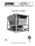
YCAL0041EC - YCAL0071EC
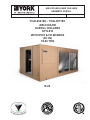
AIR-COOLED
SCROLL CHILLERS
STYLE D
WITH IPU II & I/O BOARDS
(60 Hz)
35-60 TON
LD10950
R-22
FORM 150.66-NM1 (708)
IMPORTANT!
READ BEFORE PROCEEDING!
GENERAL SAFETY GUIDELINES
This equipment is a relatively complicated apparatus.
During installation, operation, maintenance or service,
individuals may be exposed to certain components or
conditions including, but not limited to: refrigerants,
oils, materials under pressure, rotating components,
and both high and low voltage. Each of these items
has the potential, if misused or handled improperly, to
cause bodily injury or death. It is the obligation and
responsibility of operating/service personnel to identify
and recognize these inherent hazards, protect themselves,
and proceed safely in completing their tasks. Failure to
comply with any of these requirements could result in
serious damage to the equipment and the property in
which it is situated, as well as severe personal injury or
death to themselves and people at the site.
This document is intended for use by owner-authorized
operating/service personnel. It is expected that this
individual possesses independent training that will
enable them to perform their assigned tasks properly
and safely. It is essential that, prior to performing any
task on this equipment, this individual shall have read
and understood this document and any referenced
materials. This individual shall also be familiar with and
comply with all applicable governmental standards and
regulations pertaining to the task in question.
SAFETY SYMBOLS
The following symbols are used in this document to alert the reader to areas of potential hazard:
DANGER indicates an imminently
hazardous situation which, if not
avoided, will result in death or serious
injury.
CAUTION identifies a hazard which
could lead to damage to the machine,
damage to other equipment and/or
environmental pollution. Usually an
instruction will be given, together with
a brief explanation.
WARNING indicates a potentially
haz ard ous sit u a tion which, if not
avoided, could result in death or serious injury.
NOTE is used to highlight additional
information which may be helpful to
you.
External wiring, unless specified as an optional connection in the manufacturer’s product
line, is NOT to be connected inside the micro panel cabinet. Devices such as relays, switches,
transducers and controls may NOT be installed inside the panel. NO external wiring is allowed to be run through the micro panel. All wiring must be in accordance with YORK’s
published specifications and must be performed ONLY by qualified YORK personnel. YORK
will not be responsible for damages/problems resulting from improper connections to the
controls or application of improper control signals. Failure to follow this will void the
manufacturer’s warranty and cause serious damage to property or injury to persons.
2
JOHNSON CONTROLS
FORM 150.66-NM1 (708)
CHANGEABILITY OF THIS DOCUMENT
In complying with YORK’s policy for continuous product improvement, the information contained in this document
is subject to change without notice. While YORK makes no commitment to update or provide current information
automatically to the manual owner, that information, if applicable, can be obtained by contacting the nearest YORK
Engineered Systems Service office.
It is the responsibility of operating/service personnel to verify the applicability of these documents to the equipment in
question. If there is any question in the mind of operating/service personnel as to the applicability of these documents,
then prior to working on the equipment, they should verify with the owner whether the equipment has been modified
and if current literature is available.
JOHNSON CONTROLS
3
FORM 150.66-NM1 (708)
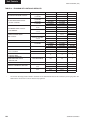
TABLE OF CONTENTS
GENERAL SAFETY GUIDELINES ......................................................................................................2
TABLE OF CONTENTS .......................................................................................................................4
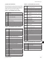
LIST OF FIGURES ...............................................................................................................................9
LIST OF TABLES...............................................................................................................................10
SECTION 1 - GENERAL CHILLER INFORMATION & SAFETY ......................................................13
INTRODUCTION .........................................................................................................................................13
WARRANTY ................................................................................................................................................13
SAFETY .......................................................................................................................................................13
Standards for Safety ...........................................................................................................................13
RESPONSIBILITY FOR SAFETY ...............................................................................................................14
ABOUT THIS MANUAL ..............................................................................................................................14
MISUSE OF EQUIPMENT ...........................................................................................................................14
Suitability for Application ...................................................................................................................14
Structural Support ...............................................................................................................................14
Mechanical Strength ..........................................................................................................................15
General Access ....................................................................................................................................15
Pressure Systems ...............................................................................................................................15
Electrical...............................................................................................................................................15
Rotating Parts ......................................................................................................................................15
Sharp Edges.........................................................................................................................................15
Refrigerants and Oils ..........................................................................................................................15
High Temperature and Pressure Cleaning ........................................................................................15
Emergency Shutdown .........................................................................................................................15
SECTION 2 - PRODUCT DESCRIPTION ..........................................................................................16
INTRODUCTION .........................................................................................................................................16
GENERAL SYSTEM DESCRIPTION ..........................................................................................................16
Compressors .......................................................................................................................................16
Cooler ...................................................................................................................................................16
Condenser ............................................................................................................................................17
Millennium Control Center..................................................................................................................17
Power Panel .........................................................................................................................................18
ACCESSORIES AND OPTIONS .................................................................................................................19
Power Options: ....................................................................................................................................19
Control Options: ..................................................................................................................................19
Compressor, Piping, Evaporator Options .........................................................................................20
Condenser and Cabinet Options........................................................................................................20
Sound Reduction Options ..................................................................................................................21
UNIT COMPONENTS ..................................................................................................................................22
CONTROL / POWER PANEL COMPONENTS ...........................................................................................23
PRODUCT IDENTIFICATION NUMBER (PIN)............................................................................................24
UNIT NOMENCLATURE .............................................................................................................................24
BASIC UNIT NOMENCLATURE .................................................................................................................24
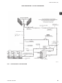
REFRIGERANT FLOW DIAGRAM .............................................................................................................29
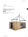
SECTION 3 - HANDLING AND STORAGE .......................................................................................30
DELIVERY AND STORAGE ........................................................................................................................30
INSPECTION ...............................................................................................................................................30
MOVING THE CHILLER ..............................................................................................................................30
Lifting Weights .....................................................................................................................................30
UNIT RIGGING ............................................................................................................................................31
4
JOHNSON CONTROLS
FORM 150.66-NM1 (708)
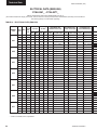
TABLE OF CONTENTS (CONT’D)
SECTION 4 - INSTALLATION ...........................................................................................................32
INSTALLATION CHECKLIST......................................................................................................................32
HANDLING ..................................................................................................................................................32
INSPECTION ...............................................................................................................................................32
LOCATION AND CLEARANCES ................................................................................................................32
Foundation ...........................................................................................................................................33
Ground Level Locations .....................................................................................................................33
Rooftop Locations ...............................................................................................................................33
Noise Sensitive Locations ..................................................................................................................33
SPRING ISOLATORS (OPTIONAL)............................................................................................................33
COMPRESSOR MOUNTING ......................................................................................................................33
REMOTE COOLER OPTION ......................................................................................................................33
CHILLED LIQUID PIPING ...........................................................................................................................33
DUCT WORK CONNECTION ....................................................................................................................34
WIRING ........................................................................................................................................................34
Evaporator Pump Start Contacts .......................................................................................................35
System Run Contacts .........................................................................................................................35
Alarm Status Contacts ........................................................................................................................35
Remote Start/Stop Contacts ...............................................................................................................35
Remote Emergency Cutoff .................................................................................................................35
PWM Input ............................................................................................................................................35
Load Limit Input...................................................................................................................................35
Flow Switch Input ................................................................................................................................35
COMPRESSOR HEATERS .........................................................................................................................35
SINGLE-POINT SUPPLY CONNECTION – TERMINAL BLOCK, NON-FUSED DISCONNECT
SWITCH OR CIRCUIT BREAKER (0041 - 0071) .......................................................................................36
SINGLE-POINT SUPPLY CONNECTION ...................................................................................................36
CONTROL WIRING .....................................................................................................................................37
SECTION 5 - COMMISSIONING .......................................................................................................38
PREPARATION – POWER OFF..................................................................................................................38
Inspection ...........................................................................................................................................38
Refrigerant Charge ..............................................................................................................................38
Service and Oil Line Valves ................................................................................................................38
Compressor Oil....................................................................................................................................38
Fans .....................................................................................................................................................38
Isolation / Protection ...........................................................................................................................38
Control Panel .......................................................................................................................................38
Power Connections .............................................................................................................................38
Grounding ............................................................................................................................................39
Supply Voltage .....................................................................................................................................39
PREPARATION – POWER ON ...................................................................................................................39
Switch Settings ....................................................................................................................................39
Compressor Heaters ...........................................................................................................................39
Water System .......................................................................................................................................39
Flow Switch ..........................................................................................................................................39
Temperature Sensor(s) .......................................................................................................................39
EQUIPMENT STARTUP CHECKLIST ........................................................................................................40
Checking the System Prior To Initial Start (No Power) ....................................................................40
Compressor Heaters (Power ON – 24 Hours Prior To Start) ...........................................................40
Panel Checks (Power ON – Both Unit Switches OFF)....................................................................40
JOHNSON CONTROLS
5
FORM 150.66-NM1 (708)
TABLE OF CONTENTS (CONT’D)
SETPOINTS ENTRY LIST ...........................................................................................................................41
CHECKING SUPERHEAT AND SUBCOOLING .........................................................................................42
LEAK CHECKING .......................................................................................................................................42
UNIT OPERATING SEQUENCE .................................................................................................................43
SECTION 6 - TECHNICAL DATA ......................................................................................................44
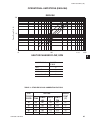
OPERATIONAL LIMITATIONS (ENGLISH) ................................................................................................44
Temperatures and Flows ....................................................................................................................44
Voltage Limitations ..............................................................................................................................44
Ethylene Glycol Correction Factors ..................................................................................................45
OPERATIONAL LIMITATIONS (SI) .............................................................................................................46
Temperatures and Flows ....................................................................................................................46
Voltage Limitations ..............................................................................................................................46
Ethylene Glycol Correction Factors ..................................................................................................47
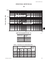
PHYSICAL DATA (ENGLISH) .....................................................................................................................48
SOUND DATA (ENGLISH) ..........................................................................................................................50
ELCTRICAL DATA (ENGLISH) ...................................................................................................................52
ELECTRICAL NOTES AND LEGEND ........................................................................................................55
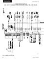
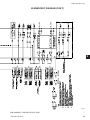
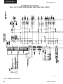
WIRING DIAGRAMS ...................................................................................................................................56
CONNECTION DIAGRAMS ........................................................................................................................63
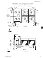
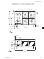
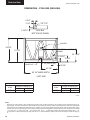
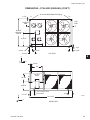
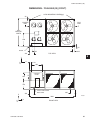
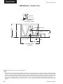
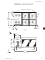
DIMENSIONS - (ENGLISH) .........................................................................................................................66
DIMENSIONS - (SI) .....................................................................................................................................80
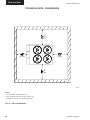
TECHNICAL DATA - CLEARANCES ..........................................................................................................94
ISOLATORS ................................................................................................................................................95
SECTION 7 - UNIT CONTROLS ......................................................................................................101
INTRODUCTION .......................................................................................................................................101
MICROPROCESSOR BOARD ..................................................................................................................101
UNIT SWITCH ...........................................................................................................................................102
DISPLAY ....................................................................................................................................................102
KEYPAD ....................................................................................................................................................102
BATTERY BACK-UP .................................................................................................................................102
TRANSFORMER ......................................................................................................................................102
SINGLE SYSTEM SELECT ANDPROGRAMMING # OF COMPRESSORS ..........................................102
“STATUS” KEY ........................................................................................................................................103
Unit Status..........................................................................................................................................103
General Status Messages .................................................................................................................103
Fault safety Status Messages ..........................................................................................................105
System Safeties ............................................................................................................................105
Unit Safeties: ................................................................................................................................107
Unit Warning ......................................................................................................................................107
STATUS KEY MESSAGES QUICK REFERENCE LIST ...........................................................................108
DISPLAY/PRINT KEYS .............................................................................................................................109
Oper Data Key ....................................................................................................................................109
Operation Data Quick Reference List ..............................................................................................112
Print Key ............................................................................................................................................. 113
Operating Data Printout ....................................................................................................................113
History Printout ................................................................................................................................. 114
History Displays ................................................................................................................................ 114
Software Version ............................................................................................................................... 116
6
JOHNSON CONTROLS
FORM 150.66-NM1 (708)
TABLE OF CONTENTS (CONT’D)
“ENTRY” KEYS......................................................................................................................................... 117
Up and Down Arrow Keys .................................................................................................................117
Enter/Adv Key .................................................................................................................................... 117
“SETPOINTS” KEYS ................................................................................................................................ 118
Cooling Setpoints ..............................................................................................................................118
Leaving Chilled Liquid Control ........................................................................................................118
Return Chilled Liquid Control ..........................................................................................................119
Remote Setpoint Control ..................................................................................................................119
Schedule/advance Day Key ..............................................................................................................119
Program Key ......................................................................................................................................121
System Trip Volts .........................................................................................................................122
Unit Trip Volts ...............................................................................................................................123
Program Key Limits and Defaults ....................................................................................................124
Setpoints Quick Reference List .......................................................................................................125
“UNIT” KEYS ...........................................................................................................................................126
Options Key .......................................................................................................................................126
CLOCK ......................................................................................................................................................130
UNIT KEYS PROGRAMMING QUICK REFERENCE LIST ......................................................................131
SECTION 8 - UNIT OPERATION .....................................................................................................132
CAPACITY CONTROL ..............................................................................................................................132
SUCTION PRESSURE LIMIT CONTROLS ..............................................................................................132
DISCHARGE PRESSURE LIMIT CONTROLS .........................................................................................132
LEAVING CHILLED LIQUID CONTROL ...................................................................................................132
LEAVING CHILLED LIQUID CONTROLOVERRIDE TO REDUCE CYCLING.........................................133
LEAVING CHILLED LIQUID SYSTEM LEAD/LAG AND COMPRESSOR SEQUENCING .....................133
RETURN CHILLED LIQUID CONTROL....................................................................................................133
RETURN CHILLLED LIQUID SYSTEM LEAD/LAG AND COMPRESSOR SEQUENCING ....................134
ANTI-RECYCLE TIMER ............................................................................................................................135
ANTI-COINCIDENCE TIMER ....................................................................................................................135
EVAPORATOR PUMP CONTROL ............................................................................................................135
EVAPORATOR HEATER CONTROL ........................................................................................................135
PUMPDOWN CONTROL ..........................................................................................................................136
CONDENSER FAN CONTROL .................................................................................................................136
LOW AMBIENT FAN CONTROL OPTION ................................................................................................138
General ...............................................................................................................................................138
Configuration (Jumpers and Potentiometers) ................................................................................139
Wiring .................................................................................................................................................140
PROGRAMMING .......................................................................................................................................141
LOAD LIMITING ........................................................................................................................................141
COMPRESSOR RUN STATUS .................................................................................................................142
ALARM STATUS .......................................................................................................................................142
EMS-PWM REMOTE TEMPERATURE RESET ........................................................................................142
BAS/EMS TEMPERATURE RESET OPTION ...........................................................................................143
JOHNSON CONTROLS
7
FORM 150.66-NM1 (708)
TABLE OF CONTENTS (CONT’D)
SECTION 9 - SERVICE AND TROUBLESHOOTING .....................................................................145
CLEARING HISTORY BUFFERS .............................................................................................................145
SERVICE MODE – OUTPUTS ..................................................................................................................145
SERVICE MODE – CHILLER CONFIGURATION .....................................................................................145
SERVICE MODE – INPUTS ......................................................................................................................146
CONTROL INPUTS/OUTPUTS .................................................................................................................147
IPU II & I/O LAYOUT .................................................................................................................................148
CHECKING INPUTS AND OUTPUTS .......................................................................................................149
Digital Inputs ......................................................................................................................................149
Analog Inputs – Temperature ...........................................................................................................149
Outside Air Sensor ............................................................................................................................149
Liquid & Refrigerant Sensor Test Points ........................................................................................150
Analog Inputs – Pressure .................................................................................................................151
Digital Outputs ...................................................................................................................................152
OPTIONAL PRINTER INSTALLATION .....................................................................................................153
Parts....................................................................................................................................................153
Assembly and Wiring ........................................................................................................................153
Obtaining a Printout ..........................................................................................................................153
TROUBLESHOOTING ..............................................................................................................................154
SECTION 10 - MAINTENANCE .......................................................................................................157
IMPORTANT ..............................................................................................................................................157
COMPRESSORS .......................................................................................................................................157
Oil Level check ..................................................................................................................................157
Oil Analysis ........................................................................................................................................157
CONDENSER FAN MOTORS ...................................................................................................................157
CONDENSER COILS ................................................................................................................................157
OPERATING PARAMETERS ....................................................................................................................157
ON-BOARD BATTERY BACK-UP ............................................................................................................157
PLATE AND FRAME HEAT EXCHANGER (EVAPORATOR) HEATER ...................................................157
OVERALL UNIT INSPECTION .................................................................................................................158
ISN CONTROL ..........................................................................................................................................159
Received Data (Control Data) ...........................................................................................................159
Transmitted Data ...............................................................................................................................159
BACNET AND MODBUS DATA COMMUNICATION ................................................................................162
8
JOHNSON CONTROLS
FORM 150.66-NM1 (708)
LIST OF FIGURES
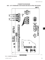
FIG. 1 – REFRIGERANT FLOW DIAGRAM ......................................................................................29
FIG. 2 – SINGLE-POINT SUPPLY CONNECTION – TERMINAL BLOCK, NON-FUSED
DISCONNECT SWITCH OR CIRCUIT BREAKER (0041 - 0071) .......................................36
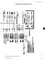
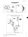
FIG. 3 – CONTROL WIRING ............................................................................................................37
FIG. 4 – CONTROL CIRCUIT, DUAL.................................................................................................56
FIG. 5 – CONTROL CIRCUIT, DUAL.................................................................................................58
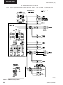
FIG. 6 – POWER CIRCUIT, DUAL .....................................................................................................60
FIG. 7 – POWER CIRCUIT, DUAL .....................................................................................................61
FIG. 8 – WIRING DETAILS ................................................................................................................62
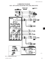
FIG. 9 – CONNECTION DIAGRAM ...................................................................................................63
FIG. 10 – CONNECTION DIAGRAM .................................................................................................64
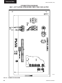
FIG. 11 – CONNECTION DIAGRAM MICROBOARD (PARTIAL) ....................................................65
FIG. 12 – UNIT CLEARANCES .........................................................................................................94
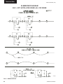
FIG. 13 – LEAVING WATER TEMPERATURE CONTROL EXAMPLE ...........................................133
FIG. 14 – SETPOINT ADJUST ........................................................................................................133
FIG. 15 – YCAL0041 – YCAL0071 FAN LOCATION (TYPICAL) ...................................................137
FIG. 16 – TYPICAL INVERTER LOCATION ...................................................................................138
FIG. 17 – INVERTER ENCLOSURE ................................................................................................138
FIG. 18 – POTENTIOMETER SETTINGS........................................................................................139
FIG. 19 – INVERTER POWER WIRING SCHEMATIC ....................................................................140
FIG. 20 – INVERTER WIRING .........................................................................................................140
FIG. 21 – FIELD AND FACTORY ELECTRICAL CONNECTIONS OPTIONAL REMOTE
TEMPERATURE RESET BOARD ...................................................................................144
FIG. 22 – IPU II & I/O LAYOUT ........................................................................................................148
FIG. 23 – MICROBOARD RELAY CONTACT ARCHITECTURE ....................................................152
FIG. 24 – PRINTER TO MICROBOARD ELECTRICAL CONNECTIONS ......................................153
JOHNSON CONTROLS
9
FORM 150.66-NM1 (708)
LIST OF TABLES
TABLE 1 – SETPOINTS ENTRY LIST...............................................................................................41
TABLE 2 – TEMPERATURES AND FLOWS.....................................................................................44
TABLE 3 – VOLTAGE LIMITATIONS ................................................................................................44
TABLE 4 – ETHYLENE GLYCOL CORRECTION FACTORS ..............................................................45
TABLE 5 – TEMPERATURES AND FLOWS (SI) ..............................................................................46
TABLE 6 – VOLTAGE LIMITATIONS ................................................................................................46
TABLE 7 – ETHYLENE GLYCOL CORRECTION FACTORS ..............................................................47
TABLE 8 – PHYSICAL DATA (ENGLISH) .........................................................................................48
TABLE 9 – SOUND DATA (ENGLISH) ..............................................................................................50
TABLE 10 – ELECTRICAL DATA (ENGLISH) ..................................................................................52
TABLE 11 – MICRO PANEL POWER SUPPLY ................................................................................54
TABLE 12 – VOLTAGE RANGE ........................................................................................................54
TABLE 13 – STATUS KEY MESSAGES QUICK REFERENCE LIST.............................................108
TABLE 14 – OPERATION DATA .....................................................................................................112
TABLE 15 – COOLING SETPOINTS, PROGRAMMABLE LIMITS AND DEFAULTS ....................120
TABLE 16 – PROGRAM KEY LIMITS AND DEFAULTS ................................................................124
TABLE 17 – SETPOINTS QUICK REFERENCE LIST ....................................................................125
TABLE 18 – UNIT KEYS PROGRAMMING QUICK REFERENCE LIST ........................................131
TABLE 19 – COMPRESSOR STAGING FOR RETURN WATER CONTROL.................................134
TABLE 20 – RETURN CHILLED LIQUID CONTROL FOR 4 COMPRESSORS (6 STEPS) ..........135
TABLE 21 – RETURN CHILLED LIQUID CONTROL FOR 4 COMPRESSORS (6 STEPS) ..........136
TABLE 22 – YCAL0041 – YCAL0071 CONDENSER FAN CONTROL USING OUTDOOR
AMBIENT TEMPERATURE AND DISCHARGE PRESSURE (DISCHARGE
PRESSURE CONTROLS WILL NOT FUNCTION AND FAN CONTROL WILL BE
BASED ON AMBIENT TEMPERATURES ONLY, UNLESS THE OPTIONAL
DISCHARGE PRESSURE .........................................................................................137
TABLE 23 – YCAL0041 – YCAL0071 CONDENSER FAN CONTROL USING DISCHARGE
PRESSURE ONLY ......................................................................................................137
TABLE 24 – INVERTER OPTION CONDENSER FAN CONTROL OPERATION ...........................141
TABLE 25 – COMPRESSOR OPERATION – LOAD LIMITING ......................................................142
TABLE 26 – MICROBOARD DIGITAL INPUTS ..............................................................................147
TABLE 27 – MICROBOARD DIGITAL OUTPUTS ..........................................................................147
TABLE 28 – MICROBOARD ANALOG INPUTS .............................................................................147
TABLE 29 – MICROBOARD ANALOG OUTPUTS .........................................................................147
TABLE 30 – OUTDOOR AIR SENSOR TEMPERATURE/VOLTAGE/ RESISTANCE
CORRELATION ..........................................................................................................149
TABLE 31 – ENTERING/LEAVING CHILLED LIQUID TEMP. SENSOR, COOLER INLET
TEMPERATURE SENSOR, AND SUCTION TEMPERATURE SENSOR:
TEMPERATURE/VOLTAGE CORRELATION ............................................................150
TABLE 32 – TROUBLESHOOTING ................................................................................................154
10
JOHNSON CONTROLS
FORM 150.66-NM1 (708)
LIST OF TABLES (CONT’D)
TABLE 33 – ISN RECEIVED DATA .................................................................................................159
TABLE 34 – ISN TRANSMITTED DATA..........................................................................................159
TABLE 35 – ISN OPERATIONAL AND FAULT CODES .................................................................161
TABLE 36 – MINIMUM, MAXIMUM AND DEFAULT VALUES ........................................................163
TABLE 37 – REAL TIME ERROR NUMBERS ................................................................................163
JOHNSON CONTROLS
11
FORM 150.66-NM1 (708)
THIS PAGE INTENTIONALLY LEFT BLANK
12
JOHNSON CONTROLS
FORM 150.66-NM1 (708)
SECTION 1 - GENERAL CHILLER INFORMATION & SAFETY
INTRODUCTION
YORK YCAL0041-0071 chillers are manufactured
to the highest design and construction standards to
ensure high performance, reliability and adaptability
to all types of air conditioning installations.
The unit is intended for cooling water or glycol
solutions and is not suitable for purposes other than
those specified in this manual.
This manual contains all the information required for
correct installation and commissioning of the unit,
together with operating and maintenance instructions.
The manuals should be read thoroughly before
attempting to operate or service the unit.
All procedures detailed in the manuals, including
installation, commissioning and maintenance tasks
must only be performed by suitably trained and
qualified personnel.
The manufacturer will not be liable for any
injury or damage caused by incorrect installation,
commissioning, operation or maintenance resulting
from a failure to follow the procedures and
instructions detailed in the manuals.
For warranty purposes, the following conditions must
be satisfied:
• The initial start of the unit must be carried out
by trained personnel from an Authorized YORK
Service Center (see Commissioning Page 38).
• Only genuine YORK approved spare parts, oils,
coolants, and refrigerants must be used.
• All the scheduled maintenance operations detailed
in this manual must be performed at the specified
times by suitably trained and qualified personnel
(see Maintenance Section, Page 157).
• Failure to satisfy any of these conditions will
automatically void the warranty (see Warranty
Policy).
SAFETY
Standards for Safety
YCAL chillers are designed and built within an ISO
9002 accredited design and manufacturing organization.
The chillers comply with the applicable sections of the
following Standards and Codes:
WARRANTY
YORK International warrants all equipment and
materials against defects in workmanship and
materials for a period of eighteen months from date of
shipment, unless labor or extended warranty has been
purchased as part of the contract.
The warranty is limited to parts only replacement and
shipping of any faulty part, or sub-assembly, which
has failed due to poor quality or manufacturing errors.
All claims must be supported by evidence that the
failure has occurred within the warranty period, and
that the unit has been operated within the designed
parameters specified.
All warranty claims must specify the unit model,
serial number, order number and run hours/starts.
Model and serial number information is printed on the
unit identification plate.
• ANSI/ASHRAE Standard 15- Safety Code for
Mechanical Refrigeration.
• ANSI/NFPA Standard 70- National Electrical
Code (N.E.C.).
• ASME Boiler and Pressure Vessel Code- Section
VIII Division 1.
• ARI Standard 550/590-98- Water Chilling
Packages Using the Vapor Compression Cycle.
• ASHRAE 90.1- Energy Efficiency compliance.
• ARI 370- Sound Rating of Large Outdoor
Refrigeration and Air Conditioning Equipment.
In addition, the chillers conform to Underwriters
Laboratories (U.L.) for construction of chillers and
provide U.L./cU.L. Listing Label.
The unit warranty will be void if any modification to
the unit is carried out without prior written approval
from YORK International.
JOHNSON CONTROLS
13
General Chiller Introduction & Safety
FORM 150.66-NM1 (708)
RESPONSIBILITY FOR SAFETY
Every care has been taken in the design and
manufacture of the unit to ensure compliance with
the safety requirements listed above. However, the
individual operating or working on any machinery is
primarily responsible for:
•
Personal safety, safety of other personnel, and
the machinery.
•
Correct utilization of the machinery in
accordance with the procedures detailed in the
manuals.
ABOUT THIS MANUAL
The following terms are used in this document to alert
the reader to areas of potential hazard.
A NOTE is used to highlight additional information,
which may be helpful to you but where there are no
special safety implications.
The contents of this manual include suggested best
working practices and procedures. These are issued
for guidance only, and they do not take precedence
over the above stated individual responsibility and/or
local safety regulations.
This manual and any other document supplied with
the unit are the property of YORK which reserves
all rights. They may not be reproduced, in whole or
in part, without prior written authorization from an
authorized YORK representative.
MISUSE OF EQUIPMENT
Suitability for Application
A WARNING is given in this document to identify a
hazard, which could lead to personal injury. Usually
an instruction will be given, together with a brief
explanation and the possible result of ignoring the
instruction.
The unit is intended for cooling water or glycol
solutions and is not suitable for purposes other than
those specified in these instructions. Any use of the
equipment other than its intended use, or operation
of the equipment contrary to the relevant procedures
may result in injury to the operator, or damage to the
equipment.
The unit must not be operated outside the design
parameters specified in this manual.
Structural Support
A CAUTION identifies a hazard which could lead to
damage to the machine, damage to other equipment
and/or environmental pollution. Usually an instruction
will be given, together with a brief explanation and
the possible result of ignoring the instruction.
14
Structural support of the unit must be provided as
indicated in these instructions. Failure to provide
proper support may result in injury to the operator, or
damage to the equipment and/or building.
JOHNSON CONTROLS
FORM 150.66-NM1 (708)
Mechanical Strength
Rotating Parts
The unit is not designed to withstand loads or stresses
from adjacent equipment, pipework or structures.
Additional components must not be mounted on the
unit. Any such extraneous loads may cause structural
failure and may result in injury to the operator, or
damage to the equipment.
Fan guards must be fitted at all times and not
removed unless the power supply has been isolated. If
ductwork is to be fitted, requiring the wire fan guards
to be removed, alternative safety measures must be
taken to protect against the risk of injury from rotating
fans.
General Access
Sharp Edges
There are a number of areas and features, which
may be a hazard and potentially cause injury when
working on the unit unless suitable safety precautions
are taken. It is important to ensure access to the unit
is restricted to suitably qualified persons who are
familiar with the potential hazards and precautions
necessary for safe operation and maintenance of
equipment containing high temperatures, pressures
and voltages.
The fins on the air-cooled condenser coils have sharp
metal edges. Reasonable care should be taken when
working in contact with the coils to avoid the risk of
minor abrasions and lacerations. The use of gloves is
recommended.
Frame rails, brakes, and other components may also
have sharp edges. Reasonable care should be taken
when working in contact with any components to
avoid risk of minor abrasions and lacerations.
Pressure Systems
Refrigerants and Oils
The unit contains refrigerant vapor and liquid under
pressure, release of which can be a danger and cause
injury. The user should ensure that care is taken
during installation, operation and maintenance to
avoid damage to the pressure system. No attempt
should be made to gain access to the component parts
of the pressure system other than by suitably trained
and qualified personnel.
Refrigerants and oils used in the unit are generally
nontoxic, non-flammable and non-corrosive, and pose
no special safety hazards. Use of gloves and safety
glasses is, however, recommended when working on
the unit. The build up of refrigerant vapor, from a
leak for example, does pose a risk of asphyxiation in
confined or enclosed spaces and attention should be
given to good ventilation.
Electrical
High Temperature and Pressure Cleaning
The unit must be grounded. No installation or
maintenance work should be attempted on the
electrical equipment without first switching power
OFF, isolating and locking-off the power supply.
Servicing and maintenance on live equipment must
only be performed by suitably trained and qualified
personnel. No attempt should be made to gain access
to the control panel or electrical enclosures during
normal operation of the unit.
High temperature and pressure cleaning methods
(e.g. steam cleaning) should not be used on any part
of the pressure system as this may cause operation of
the pressure relief device(s). Detergents and solvents,
which may cause corrosion, should also be avoided.
Emergency Shutdown
In case of emergency, the control panel is fitted
with a Unit Switch to stop the unit in an emergency.
When operated, it removes the low voltage 120
VAC electrical supply from the inverter system, thus
shutting down the unit.
JOHNSON CONTROLS
15
1
Product Description
FORM 150.66-NM1 (708)
SECTION 2 - PRODUCT DESCRIPTION
LD10950
INTRODUCTION
YORK Millennium® Air-Cooled Scroll Chillers provide
chilled water for all air conditioning applications using
central station air handling or terminal units. They are
completely self-contained and are designed for outdoor
(roof or ground level) installation. Each unit includes
hermetic scroll compressors, a liquid cooler, air cooled
condenser, and a weather resistant microprocessor
control center, all mounted on a pressed steel base.
The units are completely assembled with all
interconnecting refrigerant piping and internal wiring,
ready for field installation.
Prior to delivery, the unit is pressure-tested,
evacuated, and fully charged with Refrigerant-22
(HCFC-22) and includes an initial oil charge. After
assembly, a complete operational test is performed
with water flowing through the cooler to assure that
the refrigeration circuit operates correctly.
The unit structure is heavy-gauge, galvanized steel. This
galvanized steel is coated with baked-on powder paint,
which, when subjected to ASTM B117 1000 hour, salt
spray testing, yields a minimum ASTM 1654 rating of
“6”. Corrosion resistant wire mesh panels are added to
protect the condenser coil from incidental damage and
restrict unauthorized access to internal components.
Units are designed in accordance with NFPA 70
16
(National Electric Code), ASHRAE/ANSI 15 Safety
code for mechanical refrigeration, ASME, Listed and
labeled with Intertek Testing Services (ETL) and rated
in accordance with ARI Standard 550/590-2003.
All exposed power wiring is routed through liquidtight, non-metallic conduit.
GENERAL SYSTEM DESCRIPTION
Compressors
The chiller has suction-gas cooled, hermetic, scroll
compressors. The YCAL compressors incorporate
a compliant scroll design in both the axial and
radial direction. All rotating parts are statically and
dynamically balanced. A large internal volume and oil
reservoir provides greater liquid tolerance. Compressor
crankcase heaters are also included for extra protection
against liquid migration.
Cooler
The Brazed Plate Heat Exchanger is equipped with a
heater controlled by the microprocessor. The heater
provides freeze protection for the cooler down to -20°F (29°C) ambient. The cooler is covered with 3/4” (19mm)
flexible, closed-cell, foam insulation (K~0.25).
JOHNSON CONTROLS
FORM 150.66-NM1 (708)
Brazed plate heat exchangers shall be UL (Underwriters
Laboratories) listed. Installing contractor must include
accommodations in the chilled water piping to allow
proper drainage and venting of the heat exchanger. Water
inlet and outlet connections are grooved for compatibility
with factory supplied victaulic connections.
A strainer with a mesh size between .5 and 1.5 mm (40
mesh) is recommended upstream of the heat exchanger
to prevent clogging.
Condenser
Coils – Fin and tube condenser coils of seamless,
internally-enhanced, high-condensing-coefficient,
corrosion resistant copper tubes are arranged in
staggered rows, mechanically expanded into aluminum
fins. Integral subcooling is included. The design working
pressure of the coil is 450 PSIG (31 bar).
Low Sound Fans – The condenser fans are composed
of corrosion resistant aluminum hub and glass-fiber
reinforced composite blades molded into a low noise
airfoil section. They are designed for maximum
efficiency and are statically and dynamically balanced
for vibration free operation. They are directly driven
by independent motors, and positioned for vertical air
discharge. All blades are statically and dynamically
balanced for vibration-free operation. The fan guards
are constructed of heavy-gauge, rust-resistant, PVC
coated steel wire.
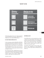
DISPLAY/PRINT of typical information:
• Chilled liquid temperatures
• Ambient temperature
• System pressures (each circuit)
• Operating hours and starts (each compressor)
• Print calls up to the liquid crystal display
• Operating data for the systems
• History of fault shutdown data for up to
the last six fault shutdown conditions.
• An RS-232 port, in conjunction with this
press-to-print button, is provided to permit
the capability of hard copy print-outs via a
separate printer (by others).
ENTRY section to:
ENTER setpoints or modify system values.
SETPOINTS updating can be performed to:
• Chilled liquid temperature setpoint and range
• Remote reset temperature range
• Set daily schedule/holiday for start/stop
• Manual override for servicing
• Low and high ambient cutouts
• Number of compressors
• Low liquid temperature cutout
• Low suction pressure cutout
• High discharge pressure cutout
• Anti-recycle timer (compressor start cycle
time)
• Anti-coincident timer (delay compressor
starts)
Motors – The fan motors are Totally Enclosed AirOver, squirrel-cage type, current protected. They feature
ball bearings that are double-sealed and permanently
lubricated.
UNIT section to:
• Set time
• Set unit options
Millennium Control Center
UNIT ON/OFF switch
All controls are contained in a NEMA 3R/12 (and
equivalent to IP55*) cabinet with hinged outer door
and includes:
Liquid Crystal Display with Light Emitting Diode backlighting for outdoor viewing:
• Two display lines
• Twenty characters per line
Color coded 12-button non-tactile keypad with sections
for:
JOHNSON CONTROLS
The microprocessor control center is capable of
displaying the following:
•
•
•
•
•
•
•
Return and leaving liquid temperature
Low leaving liquid temperature cutout setting
Low ambient temperature cutout setting
Outdoor air temperature
English or Metric data
Suction pressure cutout setting
Each system suction pressure
17
2
Product Description
FORM 150.66-NM1 (708)
• Discharge pressure (optional)
• Liquid Temperature Reset via a YORK ISN DDC
or Building Automation System (by others) via:
- a pulse width modulated (PWM) input as standard.
- a 4-20 milliamp or 0 -10 VDC input, or contact
closure with the optional B.A.S. interface option.
• Anti-recycle timer status for each system
• Anti-coincident system start timer condition
• Compressor run status
• No cooling load condition
• Day, date and time
• Daily start/stop times
• Holiday status
• Automatic or manual system lead/lag control
• Lead system definition
• Compressor starts & operating hours
(each compressor)
• Status of hot gas valves, evaporator heater
and fan operation
• Run permissive status
• Number of compressors running
• Liquid solenoid valve status
• Load & unload timer status
• Water pump status
Power Panel
Each panel contains:
• Compressor power terminals
• Compressor motor starting contactors per
l.E.C.**
• Control power terminals to accept incoming for
115-1-60 control power
• Fan contactors & overload current protection
The power wiring is routed through liquid-tight
conduit to the compressors and fans.
Provisions are included for: pumpdown at shutdown;
optional remote chilled water temperature reset and
two steps of demand load limiting from an external
building automation system. Unit alarm contacts are
standard.
The operating program is stored in non-volatile
memory (EPROM) to eliminate chiller failure due to
AC powered failure/battery discharge. Programmed
setpoints are retained in lithium battery-backed RTC
memory for 5 years minimum.
* Intensity of Protection European Standard
** International Electrotechnical Commission
18
JOHNSON CONTROLS
FORM 150.66-NM1 (708)
ACCESSORIES AND OPTIONS
POWER OPTIONS:
COMPRESSOR POWER CONNECTION – Singlepoint (YCAL0041-0071) terminal block connection is
provided as standard. The following power connections
are available as options. (See electrical data for specific
voltage and options availability) (Factory-Mounted).
SINGLE-POINT SUPPLY TERMINAL BLOCK
– (standard on YCAL0041 - 0071 models) Includes
enclosure, terminal-block and interconnecting wiring to
the compressors. Separate external protection must be
supplied, by others, in the incoming compressor-power
wiring. (Do not include this option if either the Single
Point Non Fused Disconnect Switch or Single-Point
Circuit Breaker options have been included).
SINGLE-POINT NON-FUSED DISCONNECT
SWITCH – Unit-mounted disconnect switch with
external, lockable handle (in compliance with Article
440-14 of N.E.C.), can be supplied to isolate the unit
power voltage for servicing. Separate external fusing
must be supplied, by others in the power wiring, which
must comply with the National Electrical Code and/or
local codes.
SINGLE-POINT CIRCUIT BREAKER – A unit
mounted circuit breaker with external, lockable handle
(in compliance with N.E.C. Article 440-14), can be
supplied to isolate the power voltage for servicing (this
option includes the Single-Point Power connection).
CONTROL TRANSFORMER – Converts unit power
voltage to 115-1-60 (0.5 or 1.0 KVA capacity). Factory mounting includes primary and secondary wiring
between the transformer and the control panel (Factory-Mounted).
POWER FACTOR CORRECTION CAPACITORS
– Will correct unit compressor power factors to a 0.900.95 (Factory-Mounted).
AMBIENT KIT (HIGH) – Required if units are to
operate when the ambient temperature is above 115°F
(46°C). Includes discharge pressure transducers. (This
option includes the Discharge Pressure Transducer /
Readout Capability option) (Field-Mounted).
BUILDING AUTOMATION SYSTEM INTERFACE – The factory addition of a Printed Circuit Board
to accept a 4-20 milliamp, 0-10VDC or contact closure
input to reset the leaving chiller liquid temperature from
a Building Automation System. (Only one of following
options can be offered on a unit at a time: BAS, Remote
Control Panel or Multi-unit Sequence Control) (Factory-Mounted). (The standard unit capabilities include
remote start/stop, remote water temperature reset via a
PWM input signal or up to two steps of demand (load)
limiting depending on model). (The standard control
panel can be directly connected to a YORK Building
Automated System via the standard onboard RS485
communication port).
LANGUAGE LCD AND KEYPAD DISPLAY – Spanish, French, and German unit LCD controls and keypad
displays are available. Standard language is English.
DISCHARGE PRESSURE TRANSDUCERS AND
READOUT CAPABILITY – The addition of pressure
transducers allows models to sense and display discharge
pressure. This is recommended for brine chilling applications. (This option is included with either the low or
high ambient kits) (Factory-Mounted).
•
Suction Pressure Transducers: Permits unit to
sense and display suction pressure. This capability
is standard on YCAL0041-0071 models.
MOTOR CURRENT MODULE – Capable of monitoring compressor motor current. Provides extra protection against compressor reverse rotation, phase-loss and
phase imbalance. Option consists of one module per
electrical system (Factory-Mounted).
CONTROL OPTIONS:
AMBIENT KIT (LOW) – Units will operate to 25°F (4°C). This accessory includes all necessary components
to permit chiller operation to 0°F (-18°C). (This option
includes the Discharge Pressure Transducer / Readout
Capability option). For proper head pressure control
in applications below 25°F (-4°C), where wind gusts
may exceed five mph, it is recommended that Optional
Condenser Louvered Enclosure Panels also be included
(Factory-Mounted).
JOHNSON CONTROLS
OPTIVIEW REMOTE CONTROL PANEL - Graphical interface panel to remotely control and monitor up to
8 different units. (Refer to form 201.18-SG4 for detailed
information).
MULTI-UNIT SEQUENCING – A separate Sequencing Control Center is provided to handle sequencing
control of up to eight chillers in parallel based on mixed
liquid temperature (interconnecting wiring by others).
(Only one of following options can be offered on a unit
at a time: BAS, Remote Control Panel or Multi-unit
Sequence Control) (Factory-Mounted).
19
2
Product Description
FORM 150.66-NM1 (708)
COMPRESSOR, PIPING, EVAPORATOR OPTIONS
LOW TEMPERATURE BRINE – Required for brine
chilling below 30°F (-1°C) leaving brine temperature
for YCAL0041 - 0071 models. Option includes resized
thermal expansion valve (Factory-Mounted).
CHICAGO CODE RELIEF VALVES – Unit will
be provided with relief valves to meet Chicago code
requirements (Factory-Mounted).
SERVICE ISOLATION VALVE – Service suction
and discharge (ball type) isolation valves are added to
unit per system. This option also includes a system high
pressure relief valve in compliance with ASHRAE 15
(Factory-Mounted).
HOT GAS BY-PASS – Permits continuous, stable
operation at capacities below the minimum step of compressor unloading to as low as 5% capacity (depending
on both the unit and operating conditions) by introducing an artificial load on the cooler. Hot gas by-pass is
installed on only refrigerant system #1 on two-circuited
units (Factory-Mounted).
DX COOLER 300 PSIG (21 bar) DWP WATERSIDE
– The waterside will be of 300 PSIG (21 bar) instead of
the standard 150 PSIG DWP. 300 PSIG R.F. flanges are
included on the DX cooler nozzles (Factory-Mounted).
The companion flanges will be field-supplied by others.
FLANGES (VICTAULIC TYPE) – Consists of two
(2) Flange adapters for grooved end pipe (standard 150
psi [10.5 bar] cooler).
FLOW SWITCH – The flow switch or its equivalent
must be furnished with each unit.
150 PSIG (10.5 bar) DWP – For standard units. Johnson
Controls model F61MG-1C Vapor-proof SPDT, NEMA
4X switch (150 PSIG [10.5 bar] DWP), -20°F to 250°F
(-29°C to 121°C), with 1” NPT connection for upright
mounting in horizontal pipe (Field-Mounted).
300 psig (21 bar) DWP – For units with optional 300
PSIG (21 bar) DX cooler. McDonnell & Miller model
FS74W Vapor-proof SPDT, NEMA 4X switch (300
PSIG (21 bar) DWP), -20°F to 300°F (-29°C to 149°C),
with 1¼ inch MPT connection for upright mounting in
horizontal pipe (Field-Mounted).
DIFFERENTIAL PRESSURE SWITCH – Alternative to an above mentioned flow switch. Pretempco
model DPS300AP40PF-82582-5 (300 psi max. working
pressure), SPDT 5 amp 125/250VAC switch, Range
0 - 40 PSID, deadband 0.5 - 0.8 psi, with 1/4” NPTE
Pressure Connections.
20
REMOTE DX COOLER – A split system arrangement
with the cooler, leaving & return water sensors, liquid
line solenoid valves, filter driers, sightglasses & TXVs
shipped loose for field connection to the air-cooled condensing section. The DX cooler and outdoor section will
have a nitrogen holding charge. Interconnecting rigid
piping, wiring and refrigerant are by others. Includes
YORK Service startup. See Form 150.62-NM1.1 (200)
for other application information (this option includes
the Crankcase Heater option) (Field-Mounted).
CONDENSER AND CABINET OPTIONS
Condenser coil protection against corrosive environments is available by choosing any of the following
options. For additional application recommendations,
refer to FORM 150.12-ES1 (Factory-Mounted).
PRE-COATED FIN CONDENSER COILS – The
unit's coils are constructed with black epoxy coated
aluminum fins. This can provide corrosion resistance
comparable to copper-fin coils in typical seashore locations. Either these or the post-coated coils (below) are
recommended for units being installed at the seashore
or where salt spray may hit the unit.
POST-COATED DIPPED CONDENSER COILS
– The unit's coils are constructed with dipped-cured
condenser coils. This is another choice for seashore and
other corrosive applications (with the exception of strong
alkalis, oxidizers and wet bromine, chlorine and fluorine
in concentrations greater than 100 ppm).
COPPER FIN CONDENSER COILS – The unit's
coils are constructed with copper fins. (This is not recommended for units in areas where they may be exposed
to acid rain).
ENCLOSURE PANELS (UNIT) – Tamperproof
Enclosure Panels prevent unauthorized access to units.
Enclosure Panels can provide an aesthetically pleasing alternative to expensive fencing. Additionally, for
proper head pressure control, YORK recommends the
use of :
LOUVERED PANELS (Full Unit) – Louvered panels
surround the front, back, and sides of the unit. They
prevent unauthorized access and visually screen unit
components. Unrestricted air flow is permitted through
generously sized louvered openings. This option is applicable for any outdoor design ambient temperature up
to 115°F (46°C) (Factory-Mounted).
JOHNSON CONTROLS
FORM 150.66-NM1 (708)
SOUND REDUCTION OPTIONS
SOUND ATTENUATION – One or both of the following sound attenuation options are recommended for
residential or other similar sound-sensitive locations.
Louvered Panels can be ordered for winter applications
where wind gusts may exceed five miles per hour. The
following types of enclosure options are available:
2
COMPRESSOR ACOUSTIC SOUND BLANKET
– Each compressor is individually enclosed by an acoustic sound blanket. The sound blankets are made with
one layer of acoustical absorbent textile fiber of 5/8”
(15mm) thickness; one layer of anti-vibrating heavy
material thickness of 1/8” (3mm). Both are closed by
two sheets of welded PVC, reinforced for temperature
and UV resistance (Factory-Mounted).
ULTRA QUIET FANS – Lower RPM, 8-pole fan
motors are used with steeper-pitch fans (FactoryMounted).
VIBRATION ISOLATORS – Level adjusting, spring
type 1” (25.4mm) or seismic deflection or neoprene
pad isolators for mounting under unit base rails (FieldMounted).
JOHNSON CONTROLS
21
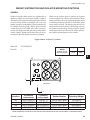
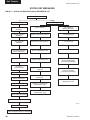
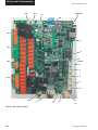
LD11419
22
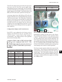
HEAT EXCHANGER
COMPRESSORS
LD11420
COMPRESSORS
LD11419
LD10950
CONDENSER COILS
LD11457
CONTROL / POWER PANEL
LD11464
Product Description
FORM 150.66-NM1 (708)
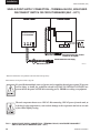
UNIT COMPONENTS
JOHNSON CONTROLS
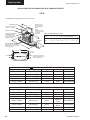
FORM 150.66-NM1 (708)
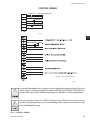
CONTROL / POWER PANEL COMPONENTS
TERMINAL BLOCK
FAN FUSES
CR1 / CR2
2
LD11459
LD11460
LD11461
LD11458
LD11462
COMPRESSOR CONTACTS
JOHNSON CONTROLS
TB1 / CTB1
LD11463
23
Product Description
FORM 150.66-NM1 (708)
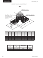
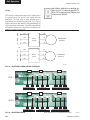
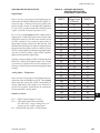
PRODUCT IDENTIFICATION NUMBER (PIN)
BASIC UNIT NOMENCLATURE
YCAL0041EC 46XBA
1 2 3 4
BASE PRODUCT TYPE
Y
C
A
U
5 6 7 8
NOMINAL CAPACITY
0
: YORK
1
: Chiller
: Air-Cooled
: Condensing
Unit
L : Scroll
9
UNIT DESIGNATOR
# # #
E : High Efficiency
# # #
Even Number:
60 HZ Nominal Tons
Odd Number:
50 HZ Nominal kW
FEATURE
MODEL
DESCRIPTION
Model (PIN 1-4)
CAP
Capacity (PIN 5-8)
UNIT
REF
Unit Designator (PIN 9)
Refrigerant (PIN 10)
VOLTS
Voltage (PIN 11 & 12)
STARTER
DESIGN
Starter (PIN 13)
Design Series (PIN 14)
24
10
REFRIGERANT
C : R-22
OPTION
YCAL
0012
0018
0021
0025
0027
0032
0041
0045
0051
0055
0061
0065
0071
E
C
17
28
40
46
58
X
D
11 12 17
14 15
VOLTAGE/STARTER
DESIGN/DEVELOPMENT LEVEL
1
2
4
4
5
7
8
0
6
8
: 200 / 3/ 60 B
: 230 / 3 / 60
: 380 / 3 / 60
: 460 / 3 / 60
: 575 / 3 / 60
X
: Across the Line
A
: Design Series A
: Engineering
Change
or PIN Level
DESCRIPTION
YCAL
0012
0018
0021
0025
0027
0032
0041
0045
0051
0055
0061
0065
0071
High Efficiency
R-22
200/3/60
230/3/60
380/3/60
460/3/60
575/3/60
Across The Line Starter
Design Series D
JOHNSON CONTROLS
FORM 150.66-NM1 (708)
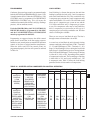
PRODUCT IDENTIFICATION NUMBER (PIN) (CON’T)
FEATURE
DEV
POWER
TRANS
PFC
AMB
BAS
LCD
RDOUT
SAFETY
SENSOR
PUMP
REMOTE
SEQ
DESCRIPTION
Developement Level (PIN 15)
OPTION
A
SX
Power Field (PIN 16 & 17)
SD
BX
QQ
X
Cntrl Transformer (PIN 18)
T
Q
X
Power Factor Capacitor (PIN 19) C
Q
X
L
Ambient Kits (PIN 20)
H
A
Q
X
BAS Reset/Offset (PIN 21)
M
T
Q
X
S
Language (PIN 22)
F
G
Q
X
Readout Kits (PIN 23)
R
Q
Safety Codes (PIN 24)
L
X
(PIN 25)
Q
X
(PIN 26)
C
Q
X
Remote Panel (PIN 27)
O
Q
X
Sequence Kit (PIN 28)
S
Q
JOHNSON CONTROLS
DESCRIPTION
Development Level A
Single Point Terminal Block
Single Point Non-Fused Disconnect
Single Point Circuit Breaker
Special Power Option Required
No Control Transformer Required
Control Transformer Required
Special Control Transformer Required
No Power Capacitor Required
Power Capacitor Required
Special Power Capacitor Required
No Ambient Kits Required
Low Ambient Kits Required
High Ambient Kits Required
High/Low Ambient Kits Required
Special Ambient Kits Required
No BAS Reset/Offset Required
ISN Microgateway Required
BAS Reset/Offset Required
Special BAS Reset/Offset Required
English
Spanish
French
German
Special Language Required
No Readout Kit Required
Discharge Readout Kit Required
Special Pressure Readout Required
N American Safety Code(Cul/Cet)
No Option Required
Special Quote
No Motor Current
Motor Current Readout
Special Quote
No Remote Panel Required
OptiView Remote Panel Required
Special Remote Panel Required
No Sequence Kit Required
Sequence Kit Required= {SEQ/S}
Special Sequence Required
25
2
Product Description
FORM 150.66-NM1 (708)
PRODUCT IDENTIFICATION NUMBER (PIN) (CON’T)
FEATURE
TEMP
DESCRIPTION
Leaving Water Temp
(PIN 29, 30)
CHICAGO
Chicago Code Kit (PIN 31)
VALVES
Valves (PIN 32)
HGBP
Hot Gas Bypass (PIN 33)
GAUGE
(PIN 34)
OVERLOAD
(PIN 35)
PIN 36
(PIN 36)
HTR
Crankcase Heater (PIN 37)
DWP
DWP (PIN 38)
INS
Insulation (PIN 39)
FLANGES
Flanges (PIN 40)
FLOW
Flow Switch (PIN 41)
OPTION
NUM
QQ
X
C
S
B
Q
X
Q
X
1
2
Q
X
Q
X
Q
X
Q
X
Q
X
3
Q
X
D
Q
X
V
Q
X
S
T
U
D
E
F
Q
26
DESCRIPTION
Leaving Water Temp=
{TEMP/NUM} Degrees
Special LWT Requirements
No Chicago Code Kit Required
Chicago Code Kit Required
Service Isolation Valves
Both Chicago Code & Serv Isolation
Special Chicago Code Kit Required
Standard Valves Required
Special Optional Valves Required
No Hot Gas Bypass Required
Hot Gas Bypass Required-1 Circuit
Hot Gas Bypass Required-2 Circuit
Special Hot Gas Required
No Option Required
Special Quote
No Option Required
Special Quote
No Option Required
Special Quote
Crankcase Heater Standard
Special Crankcase Heater Required
150 psig DWP Waterside
300 psig DWP Waterside
Special DWP
Standard Insulation
Double Thick Insulation
Special Insulation Required
Standard Victaulic
Victaulic to Flange Adapter
Special Flanges Required
No Flow Switch Required
One Flow Switch Required
Two Flow Switches Required
Three Flow Switches Required
One Differential Pressure Switch
Required
Two Differential Pressure Switches
Required
Three Differential Pressure Switches
Required
Special Flow Switch Required
JOHNSON CONTROLS
FORM 150.66-NM1 (708)
PRODUCT IDENTIFICATION NUMBER (PIN) (CON’T)
FEATURE
DESCRIPTION
VESSEL
Vessel Codes (PIN 42)
CLR
Cooler (PIN 43)
PIN 44
(PIN 44)
COILS
Coils (PIN 45)
PIN 46
(PIN 46)
FANMOTORS
Fan Motors (PIN 47)
ENCL
Enclosure Panel (PIN 48)
ACOUSTIC
Acoustic Blanket (PIN 49)
PIN 50
(PIN 50)
PIN 51
(PIN 51)
FANS
Sound Fans (PIN 52)
PAINT
(PIN 53)
ISOL
Vibration Isolators (PIN 54)
JOHNSON CONTROLS
OPTION
X
A
Q
X
R
Q
X
Q
X
B
C
P
Q
X
Q
X
Q
1
7
8
Q
X
B
Q
X
Q
X
Q
X
L
Q
X
Q
X
1
N
S
Q
DESCRIPTION
UL Pressure Code Vessel
ASME Pressure Vessel Code
Special Pressure Vessel Code
Standard Cooler Required
Remote Cooler Required
Special Cooler Required
No Option Required
Special Quote
Aluminum Coil
Pre-Coated Fin Coil
Copper Coil
Post-Coated Dipped Coil
Special Coil
No Option Required
Special Quote
TEAO Fan Motors
Special Fan Motors Required
Wire Enclosures-Factory
Louvered Enclosure-Factory
Louvered Enclosures-Field
Special Encolsures Panels
No Acoustic Blanket Required
Acoustic Blanket Required
Special Acoustic Blanket Required
No Option Required
Special Quote
No Option Required
Special Quote
Standard Low Sound Fans Required
Ultra Low Sound Fans Required
Special Sound Fans Required
No Option Required
Special Quote
No Isolators Required
1” Deflection Isolators Required
Neoprene Isolators Required
Seismic Isolators Required
Special Isolators Required
2
27
Product Description
FORM 150.66-NM1 (708)
PRODUCT IDENTIFICATION NUMBER (PIN) (CON’T)
FEATURE
DESCRIPTION
WARRANTY
Warranty (PIN 55)
REFWTY
Refrigerant Warranty (PIN 56)
SHIP
Ship Instructions (PIN 57)
PIN 58
(PIN 58)
PIN 59
(PIN 59)
PIN 60
(PIN 60)
MFG
Plant of Mfg. (PIN 61)
LOC
Mfg. Location
YW
YorkWorks Version
SQ
Special Quote
28
OPTION
X
B
C
D
E
F
G
H
X
1
2
5
X
A
B
C
Q
X
Q
X
Q
X
Q
R
MEX
SAT
CV
UV
Q
DESCRIPTION
1st Year Parts Only
1st Year Parts & Labor
2nd Year Parts Only
2nd Parts & Labor
5 Year Compressor Parts Only
5 Year Compressor Parts & Labor
5 Year Unit Parts Only
5 Year Unit Parts & labor
No Refrigerant Warranty Required
1 Year Refrigerant
2 Year Refrigerant
5 Year Refrigerant
No Option Required
Buy American Act Compliance
Both Buy American Act Compliance
and Container Shipping Kit
Container Shipping
Special Quote
No Option Required
Special Quote
No Option Required
Special Quote
No Option Required
Special Quote
Plant of Manufacture-Monterrey
Mexico
San Antonio
YorkWorks ConVersion
YorkWorks Version
Special Quote
JOHNSON CONTROLS
FORM 150.66-NM1 (708)
REFRIGERANT FLOW DIAGRAM
2
AIR COOLED CONDENSERS
HOT DISCHARGE
GAS LINE
“OPTIONAL”
“OPTIONAL”
DISCHARGE LINE
BALL VALVE
“OPTIONAL”
“OPTIONAL”
SERVICE VALVE
“OPTIONAL”
“OPTIONAL”
“OPTIONAL”
LD11417
FIG. 1 – REFRIGERANT FLOW DIAGRAM
JOHNSON CONTROLS
29
Handling and Storage
FORM 150.66-NM1 (708)
SECTION 3 - HANDLING AND STORAGE
DELIVERY AND STORAGE
MOVING THE CHILLER
To ensure consistent quality and maximum reliability,
all units are tested and inspected before leaving the
factory. Units are shipped completely assembled
and containing refrigerant under pressure. Units are
shipped without export crating unless crating has been
specified on the Sales Order.
Prior to moving the unit, ensure that the installation
site is suitable for installing the unit and is easily
capable of supporting the weight of the unit and all
associated services.
If the unit is to be put into storage, prior to
installation, the following precautions should be
observed:
• The chiller must be “blocked” so that the base is
not permitted to sag or bow.
• Ensure that all openings, such as water
connections, are securely capped.
• Do not store where exposed to ambient air
temperatures exceeding 110°F (43°C).
• The condensers should be covered to protect
the fins from potential damage and corrosion,
particularly where building work is in progress.
• The unit should be stored in a location where there
is minimal activity in order to limit the risk of
accidental physical damage.
The units are designed to be lifted using cables. A
spreader bar or frame should be used in order to
prevent damage to the unit from the lifting chains.
Units are provided with lifting eyes in the sides of the
base frame, which can be attached to directly using
shackles or safety hooks.
The unit must only be lifted by the base
frame at the points provided. Never
move the unit on rollers, or lift the unit
using a forklift truck.
Care should be taken to avoid damaging the
condenser cooling fins when moving the unit.
Lifting Weights
For details of weights and weight distribution, refer to
the data shipped in the chiller information packet and
unit nameplate.
• To prevent inadvertent operation of the pressure
relief devices the unit must not be steam cleaned.
• It is recommended that the unit is periodically
inspected during storage.
INSPECTION
Remove any transit packing and inspect the unit to
ensure that all components have been delivered and
that no damage has occurred during transit. If any
damage is evident, it should be noted on the carrier’s
freight bill and a claim entered in accordance with the
instructions given on the advice note.
Major damage must be reported immediately to your
local YORK representative.
30
JOHNSON CONTROLS
FORM 150.66-NM1 (708)
UNIT RIGGING
Use spreader bars to avoid lifting chains hitting the
chiller.
3
Never lift the chiller using a forklift or
by hooking to the top rails. Use only
the lifting holes provided.
Lifting Instructions are placed on a label on the chiller
and on the shipping bag.
LD10951
JOHNSON CONTROLS
31
Installation
FORM 150.66-NM1 (708)
SECTION 4 - INSTALLATION
To ensure warranty coverage, this
equipment must be commissioned
and serviced by an authorized YORK
service mechanic or a qualified service
person experienced in chiller installation. Installation must comply with
all applicable codes, particularly in
regard to electrical wiring and other
safety elements such as relief valves,
HP cutout settings, design working
pressures, and ventilation requirements consistent with the amount and
type of refrigerant charge.
The unit should be lifted by inserting
hooks through the holes provided in unit
base rails. Spreader bars should be used
to avoid crushing the unit frame rails with
the lifting chains (See below).
Lethal voltages exist within the control
panels. Before servicing, open and tag
all disconnect switches.
INSTALLATION CHECKLIST
The following items, 1 through 5, must be checked
before placing the units in operation.
1. Inspect the unit for shipping damage.
2. Rig unit using spreader bars.
3. Open the unit only to install water piping system.
Do not remove protective covers from water connections until piping is ready for attachment. Check
water piping to ensure cleanliness.
4. Pipe unit using good piping practice (see ASHRAE
handbook section 215 and 195).
5. Check to see that the unit is installed and operated
within limitations (Refer to LIMITATIONS).
The following pages outline detailed procedures to be
followed to install and start-up the chiller.
HANDLING
These units are shipped as completely assembled units
containing full operating charge, and care should be
taken to avoid damage due to rough handling.
LD10951
INSPECTION
Immediately upon receiving the unit, it should be
inspected for possible damage which may have
occurred during transit. If damage is evident, it should
be noted in the carrier’s freight bill. A written request
for inspection by the carrier’s agent should be made at
once. See “Instruction” manual, Form 50.15-NM for
more information and details.
LOCATION AND CLEARANCES
These units are designed for outdoor installations on
ground level, rooftop, or beside a building. Location
should be selected for minimum sun exposure and to
insure adequate supply of fresh air for the condenser.
The units must be installed with sufficient clearances for
air entrance to the condenser coil, for air discharge away
from the condenser, and for servicing access.
In installations where winter operation is intended and
snow accumulations are expected, additional height must
be provided to ensure normal condenser air flow.
Clearances are listed under “Notes” in the
“DIMENSIONS” section.
32
JOHNSON CONTROLS
FORM 150.66-NM1 (708)
Foundation
The unit should be mounted on a flat and level
foundation, floor, or rooftop capable of supporting the
entire operating weight of the equipment. See PHYSICAL
DATA for operating weight. If the unit is elevated beyond
the normal reach of service personnel, a suitable catwalk
must be capable of supporting service personnel, their
equipment, and the compressors.
Ground Level Locations
It is important that the units be installed on a substantial
base that will not settle. A one piece concrete slab
with footers extended below the frost line is highly
recommended. Additionally, the slab should not be tied
to the main building foundations as noise and vibration
may be transmitted. Mounting holes are provided in the
steel channel for bolting the unit to its foundation (see
DIMENSIONS).
For ground level installations, precautions should be
taken to protect the unit from tampering by or injury to
unauthorized persons. Screws and/or latches on access
panels will prevent casual tampering. However, further
safety precautions such as a fenced-in enclosure or
locking devices on the panels may be advisable.
Rooftop Locations
Choose a spot with adequate structural strength to
safely support the entire weight of the unit and service
personnel. Care must be taken not to damage the roof.
Consult the building contractor or architect if the roof
is bonded. Roof installations should have wooden
beams (treated to reduce deterioration), cork, rubber,
or vibration isolators under the base to minimize
vibration.
Noise Sensitive Locations
Efforts should be made to assure that the chiller is not
located next to occupied spaces or noise sensitive areas
where chiller noise level would be a problem. Chiller
noise is a result of compressor and fan operation.
Considerations should be made utilizing noise levels
published in the YORK Engineering Guide for
the specific chiller model. Sound blankets for the
compressors and low sound fans are available.
JOHNSON CONTROLS
SPRING ISOLATORS (OPTIONAL)
When ordered, four (4) isolators will be furnished.
Identify the isolator, locate at the proper mounting point,
and adjust per instructions.
COMPRESSOR MOUNTING
The compressors are mounted on four (4) rubber
isolators. The mounting bolts should not be loosened
or adjusted at installation of the chiller.
REMOTE COOLER OPTION
For units using remote cooler option, refer to instructions
included with miscellaneous cooler parts kit.
The unit and remote cooler are shipped with a 6 lb. (2.7
kg) nitrogen holding charge. The nitrogen charge must
be removed, and system evacuated, and the refrigerant
charge must be weighed-in according to the operating
charge listed under PHYSICAL DATA. Additional
charge must also be added for the refrigerant lines.
CHILLED LIQUID PIPING
General – When the unit(s) has been located in its
final position, the unit water piping may be connected.
Normal installation precautions should be observed in
order to receive maximum operating efficiencies. Piping
should be kept free of all foreign matter. All chilled water
evaporator piping must comply in all respects with local
plumbing codes and ordinances.
Since elbows, tees and valves decrease pump capacity,
all piping should be kept as straight and as simple as
possible. All piping must be supported independent
of the chiller.
Consideration should be given to compressor access when laying out water
piping. Routing the water piping too
close to the unit could make compressor servicing/replacement difficult.
Hand stop valves should be installed in all lines to facilitate servicing.
Piping to the inlet and outlet connections of the chiller
should include high-pressure rubber hose or piping
loops to ensure against transmission of water pump
vibration. The necessary components must be obtained
in the field.
33
4
Installation
FORM 150.66-NM1 (708)
Drain connections should be provided at all low points
to permit complete drainage of the cooler and system
water piping.
A small valve or valves should be installed at the highest
point or points in the chilled water piping to allow any
trapped air to be purged. Vent and drain connections
should be extended beyond the insulation to make them
accessible.
The Flow Switch MUST NOT be used
to start and stop the chiller (i.e. starting and stopping the chilled water
pump). It is intended only as a safety
switch.
DUCT WORK CONNECTION
General Requirements
The piping to and from the cooler must be designed to
suit the individual installation. It is important that the
following considerations be observed:
1. The chilled liquid piping system should be laid out
so that the circulating pump discharges directly
into the cooler. The suction for this pump should
be taken from the piping system return line and not
the cooler. This piping scheme is recommended,
but is not mandatory.
2. The inlet and outlet cooler connection sizes are 3”
(YCAL0041 - 0071).
3. A strainer, preferably 40 mesh, must be installed
in the cooler inlet line just ahead of the cooler. This
is important to protect the cooler from entrance of
large particles which could cause damage to the
evaporator.
4. All chilled liquid piping should be thoroughly
flushed to free it from foreign material before
the system is placed into operation. Use care not
to flush any foreign material into or through the
cooler.
The following duct work recommendations are
intended to ensure satisfactory operation of the unit.
Failure to follow these recommendations could cause
damage to the unit, or loss of performance, and may
invalidate the warranty.
When ducting is to be fitted to the fan discharge it
is recommended that the duct should be the same
cross-sectional area as the fan outlet and straight for
at least three feet (1 meter) to obtain static regain
from the fan. Duct work should be suspended with
flexible hangers to prevent noise and vibration being
transmitted to the structure. A flexible joint is also
recommended between the duct attached to the fan
and the next section for the same reason. Flexible
connectors should not be allowed to concertina.
The unit(s) is not designed to take structural loading.
No significant amount of weight should be allowed
to rest on the fan outlet flange, deck assemblies or
condenser coil module. No more than 3 feet (1 meter)
of light construction duct work should be supported
by the unit. Where cross winds may occur, any duct
work must be supported to prevent side loading on the
unit.
5. As an aid to servicing, thermometers and pressure
gauges should be installed in the inlet and outlet
water lines.
If the ducts from two or more fans are to be combined
into a common duct, back-flow dampers should be
fitted in the individual fan ducts. This will prevent recirculation of air when only one of the fans is running.
6. The chilled water lines that are exposed to outdoor
ambients should be wrapped with supplemental
heater cable and insulated to protect against freezeup during low ambient periods, and to prevent
formation of condensation on lines in warm humid
locations.
Units are supplied with outlet guards for safety and
to prevent damage to the fan blades. If these guards
are removed to fit duct work, adequate alternative
precautions must be taken to ensure persons cannot be
harmed or put at risk from rotating fan blades.
WIRING
7. A chilled water flow switch, (either by YORK or
others) MUST be installed in the leaving water
piping of the cooler. There should be a straight
horizontal run of at least 5 diameters on each side
of the switch. Adjust the flow switch paddle to the
size of the pipe in which it is to be installed (see
manufacturer’s instructions furnished with the
switch). The switch is to be wired to terminals 13
- 14 of CTB1 located in the control panel, as shown
on the unit wiring diagram.
34
Liquid Chillers are shipped with all factory-mounted
controls wired for operation.
Field Wiring – Power wiring must be provided
through a fused disconnect switch to the unit terminals
(or optional molded disconnect switch) in accordance
with N.E.C. or local code requirements. Minimum
circuit ampacity and maximum dual element fuse size
are given in Table 10.
JOHNSON CONTROLS
FORM 150.66-NM1 (708)
A 120-1-60, 15 amp source must be supplied for the
control panel through a fused disconnect when a control
panel transformer (optional) is not provided (Refer to
Fig. 2).
See unit wiring diagrams for field and power wiring
connections, chilled water pump starter contacts,
alarm contacts, compressor run status contacts, PWM
input, and load limit input. Refer to section on UNIT
OPERATION for a detailed description of operation
concerning aforementioned contacts and inputs.
Evaporator Pump Start Contacts
Terminal block TB1 – terminals 23 to 24, are normallyopen contacts that can be used to switch field supplied
power to provide a start signal to the evaporator pump
contactor. The contacts will be closed when any of the
following conditions occur:
1. Low Leaving Chilled Liquid Fault
2. Any compressor is running
3. Daily schedule is not programmed OFF and the
Unit Switch is ON
The pump will not run if the micro panel has been
powered up for less than 30 seconds, or if the pump
has run in the last 30 seconds, to prevent pump motor
overheating. Refer to Fig. 3 and unit wiring diagram.
System Run Contacts
Contacts are available to monitor system status.
Normally-open auxiliary contacts from each compressor
contactor are wired in parallel with TB1 – terminals 25
to 26 for system 1, and TB1 – terminals 27 to 28 for
system 2 (YCAL0041 - YCAL0071). Refer to Fig. 3
and unit wiring diagram.
Alarm Status Contacts
Normally-open contacts are available for each refrigerant
system. These normally-open contacts close when the
system is functioning normally. The respective contacts
will open when the unit is shut down on a unit fault, or
locked out on a system fault. Field connections are at
TB1 terminals 29 to 30 (system 1), and terminals 31 to
32 (system 2 YCAL0041 - YCAL0071). Refer to Fig.
3 and unit wiring diagram.
Remote Start/Stop Contacts
To remotely start and stop the chiller, dry contacts can
be wired in series with the flow switch and CTB1 - terminals 13 to 14. Refer to Fig. 3 and unit wiring diagram.
JOHNSON CONTROLS
Remote Emergency Cutoff
Immediate shutdown of the chiller can be accomplished
by opening a field-installed dry contact to break the electrical circuit between terminals 5 to L on terminal block
TB1. The unit is shipped with a factory jumper installed
between terminals 5 to L, which must be removed if
emergency shutdown contacts are installed. Refer to
Fig. 3 and unit wiring diagram.
PWM Input
The PWM input allows reset of the chilled liquid setpoint
by supplying a “timed” contact closure. Field wiring
should be connected to CTB1 – terminals 13 to 20. A
detailed explanation is provided in the Unit Control
section. Refer to Page 37 & and unit wiring diagram.
Load Limit Input
Load limiting is a feature that prevents the unit from
loading beyond a desired value. The unit can be “load
limited” either 33%, 40%, 50%, 66% or 80%, depending
on the number of compressors on unit. The field
connections are wired to CTB1 – terminals 13 to 21, and
work in conjunction with the PWM inputs. A detailed
explanation is provided in the Unit Control section. Refer
to Page 37 and unit wiring diagram.
When using the Load Limit feature,
the PWM feature will not function
– SIMULTANEOUS OPERATION
OF LOAD LIMITING AND TEMPERATURE RESET (PWM INPUT)
CANNOT BE DONE.
Flow Switch Input
The flow switch is field wired to CTB1 terminals 13
- 14. See Page 37 and unit wiring diagram.
COMPRESSOR HEATERS
Compressor heaters are standard. SM90 - SM160
compressors utilize 50W heaters; SM185 compressors
utilize 75W heaters. If power is OFF more than two
hours, the crankcase heaters must be energized for 18
- 24 hours prior to restarting a compressor. This will
assure that liquid slugging and oil dilution does not
damage the compressors on start.
35
4
Installation
FORM 150.66-NM1 (708)
SINGLE-POINT SUPPLY CONNECTION – TERMINAL BLOCK, NON-FUSED
DISCONNECT SWITCH OR CIRCUIT BREAKER (0041 - 0071)
Power Panel
Control Panel
2
L
Terminal Block,
NF Disconnect SW
or Circuit Breaker
MICROPANEL
CTB2
Flow Switch
GRD
1L1 1L2 1L3
13
14
CTB1
Field Provided 120-1-60
Micropanel Power Supply if Control
Transformer not Supplied
Field Provided Unit Power Supply
LD07719
See electrical note 9
* Models YCAL0040-0071 Only (Models YCAL0014-0034 are Single Point)
Electrical Notes and Legend located on page 55.
It is possible that multiple sources of power can be supplying the unit power panel. To prevent
serious injury or death, the technician should verify that NO LETHAL VOLTAGES are
present inside the panel AFTER disconnecting power, PRIOR to working on equipment.
The unit evaporator heater uses 120VAC. Disconnecting 120VAC power from the unit, at
or below freezing temperatures, can result in damage to the evaporator and unit as a result
of the chilled liquid freezing.
FIG. 2 – SINGLE-POINT SUPPLY CONNECTION – TERMINAL BLOCK, NON-FUSED DISCONNECT
SWITCH OR CIRCUIT BREAKER (0041 - 0071)
36
JOHNSON CONTROLS
FORM 150.66-NM1 (708)
CONTROL WIRING
FLOW SW
REMOTE START/STOP
13
14
13
20
13
PWM INPUT
LOAD LIMIT INPUT
21
CTB1
LD07725
4
*
* Factory wired with optional transformer.
TB1
LD07730
It is possible that multiple sources of power can be supplying the unit power panel. To prevent
serious injury or death, the technician should verify that NO LETHAL VOLTAGES are
present inside the panel AFTER disconnecting power, PRIOR to working on equipment.
The unit evaporator heater uses 120VAC. Disconnecting 120VAC power from the unit, at
or below freezing temperatures, can result in damage to the evaporator and unit as a result
of the chilled liquid freezing.
FIG. 3 – CONTROL WIRING
JOHNSON CONTROLS
37
Commissioning
FORM 150.66-NM1 (708)
SECTION 5 - COMMISSIONING
Commissioning of this unit should
only be carried out by YORK Authorized personnel.
Commissioning personnel should be thoroughly
familiar with the information contained in this
literature, in addition to this section.
Perform the commissioning using the detailed checks
outlined in the EQUIPMENT START-UP CHECK
LIST (Page 40) as the commissioning procedure is
carried out.
PREPARATION – POWER OFF
The following basic checks should be made with the
customer power to the unit switched OFF.
Inspection
Inspect unit for installation damage. If found, take
action and/or repair as appropriate.
Refrigerant Charge
Packaged units are normally shipped as standard
with a full refrigerant operating charge. Check that
refrigerant pressure is present in both systems and
that no leaks are apparent. If no pressure is present, a
leak test must be undertaken, the leak(s) located and
repaired. Remote systems and units are supplied with
a nitrogen holding charge. These systems must be
evacuated with a suitable vacuum pump/recovery unit
as appropriate to below 500 microns.
Do not liquid charge with static water in the cooler.
Care must also be taken to liquid charge slowly to
avoid excessive thermal stress at the charging point.
Once the vacuum is broken, charge into the condenser
coils with the full operating charge as given in the
Technical Data Section.
Service and Oil Line Valves
Open each compressor suction, economizer, and
discharge service valve. If valves are of the back-seat
type, open them fully (counterclockwise) then close
one turn of the stem to ensure operating pressure
is fed to pressure transducers. Open the liquid line
service valve and oil return line ball valve fully in
each system.
38
Compressor Oil
To add oil to a circuit - connect a YORK hand oil
pump (Part No. 470-10654-000) to the 1/4” oil
charging valve on the oil separator piping with a
length of clean hose or copper line, but do not tighten
the flare nut. Using clean oil of the correct type (“F”
oil), pump oil until all air has been purged from the
hose then tighten the nut. Stroke the oil pump to add
oil to the oil system. The oil level should be between
the middle of the lower and middle of the upper
sight glasses of the oil separator. Approximately 45 gallons is present in the each refrigerant system,
with typically 1-2 gallons in each oil separator. Oil
levels in the oil separators above the top sight glass
in either oil separator should be avoided and may
cause excessive oil carryover in the system. High oil
concentration in the system may cause nuisance trips
resulting from incorrect readings on the level sensor
and temperature sensors. Temperature sensor errors
may result in poor liquid control and resultant liquid
overfeed and subsequent damage to the compressor.
Fans
Check that all fans are free to rotate and are not
damaged. Ensure blades are at the same height when
rotated. Ensure fan guards are securely fixed.
Isolation / Protection
Verify all sources of electrical supply to the unit are
taken from a single point of isolation. Check that
the maximum recommended fuse sizes given in the
Technical Data Section has not been exceeded.
Control Panel
Check the panel to see that it is free of foreign
materials (wire, metal chips, etc.) and clean out if
required.
Power Connections
Check that the customer power cables are connected
correctly to the terminal blocks or optional circuit
breaker. Ensure that connections of power cables
within the panels to the circuit breaker or terminal
blocks are tight.
JOHNSON CONTROLS
FORM 150.66-NM1 (708)
Grounding
Water System
Verify that the unit’s protective ground terminal(s)
are properly connected to a suitable grounding point.
Ensure that all unit internal ground connections are
tight.
Verify the chilled liquid system has been installed
correctly, and has been commissioned with the correct
direction of water flow through the cooler. The inlet
should be at the refrigerant piping connection end of
the cooler. Purge air from the top of the cooler using
the plugged air vent mounted on the top of the cooler
body.
Supply Voltage
Verify that the site voltage supply corresponds to the
unit requirement and is within the limits given in the
Technical Data Section.
PREPARATION – POWER ON
Perform the commissioning using
the detailed checks outlined in the
EQUIPMENT
S TA R TUP CHECK SHEET as the
commissioning procedure is carried
out.
Apply power to the chiller. Turn ON the option panel
circuit breaker if supplied.
The machine is now live!
Flow rates and pressure drops must be within the
limits given in the Technical Data Section. Operation
outside of these limits is undesirable and could cause
damage.
If mains power must be switched OFF for extended
maintenance or an extended shutdown period, the
compressor suction, discharge and economizer service
stop valves should be closed (clockwise). If there is
a possibility of liquid freezing due to low ambient
temperatures, the coolers should be drained or power
should be applied to the chiller. This will allow the
cooler heater to protect the cooler from freezing down
to –20°F. Before placing the unit back in service,
valves should be opened and power must be switched
on (if power is removed for more than 8 hours) for
at least 8 hours (24 hours if ambient temperature is
below 86°F [30°C]) before the unit is restarted.
Flow Switch
Switch Settings
Assure the chiller OFF/ON UNIT switch at the
bottom of the keypad is OFF. Place the optional
circuit breaker handle on the panel door to ON. The
customer’s disconnection devices can now be set to
ON.
Verify a chilled water flow switch is correctly fitted in
the customer’s piping on the cooler outlet, and wired
into the control panel correctly using shielded cable.
There should be a straight run of at least 5 pipe
diameters on either side of the flow switch. The flow
switch should be connected to terminals 2 and 13 in
the panel.
Temperature Sensor(s)
Verify the control panel display is illuminated. Assure
the system switches under the SYSTEM SWITCHES
Key are in the OFF position.
Compressor Heaters
Verify the compressor heaters are energized. If
the ambient temperature is above 96°F (36°C) the
compressor heaters must be on for at least 8 hours
before start-up to ensure all refrigerant liquid is driven
out of the compressor and the oil. If the ambient
temperature is below 86°F (30°C), allow 24 hours.
JOHNSON CONTROLS
Ensure the leaving liquid temperature sensor is coated
with heat conductive compound (Part No. 013-00890000) and is inserted to the bottom of the water outlet
sensor well in the cooler. This sensor also provides
some freeze protection and must always be fully
inserted in the water outlet sensor well.
39
5
Commissioning
FORM 150.66-NM1 (708)
EQUIPMENT STARTUP CHECKLIST
JOB NAME: ______________________________
SALES ORDER #: _________________________
LOCATION: ______________________________
SOLD BY: ________________________________
INSTALLING
CONTRACTOR: ___________________________
START-UP
TECHNICIAN/
COMPANY: _______________________________
START-UP DATE : _________________________
CHILLER MODEL #: _______________________
SERIAL #: ______________________________
CHECKING THE SYSTEM
PRIOR TO INITIAL START (NO POWER)
Unit Checks
1. Inspect the unit for shipping or installation damage.
2. Assure that all piping has been completed.
3. Visually check for refrigerant piping leaks.
4. Open suction line ball valve, discharge line ball
valve, and liquid line valve for each system.
5. The compressor oil level should be maintained so
that an oil level is visible in the sight glass. The
oil level can only be tested when the compressor
is running in stabilized conditions, guaranteeing
that there is no liquid refrigerant in the lower shell
of the compressor. In this case, the oil should be
between 1/4 and 1/2 in the sight glass. At shutdown, the oil level can fall to the bottom limit of
the oil sight glass.
6. Assure water pumps are on. Check and adjust
water pump flow rate and pressure drop across
the cooler (see OPERATIONAL LIMITATIONS).
Verify flow switch operation.
Excessive flow may cause catastrophic
damage to the evaporator.
40
❑ 7. Check the control panel to ensure it is free of
foreign material (wires, metal chips, etc.).
❑ 8. Visually inspect wiring (power and control). Wiring MUST meet N.E.C. and local codes.
❑ 9. Check tightness of power wiring inside the power
panel on both sides of the motor contactors and
overloads.
❑10. Check for proper size fuses in main and control
circuits, and verify overload setting corresponds
with RLA and FLA values in electrical tables.
❑11. Assure 120VAC Control Power to TB1 has 15
amp minimum capacity.
❑ 12. Be certain all water temp sensors are inserted
completely in their respective wells and are coated
with heat conductive compound.
❑13. Assure that evaporator TXV bulbs are strapped
onto the suction lines at 4 or 8 o’clock positions
or suction temp. sensors if EEVs are installed.
COMPRESSOR HEATERS
(POWER ON – 24 HOURS PRIOR TO START)
❑ 1. Apply 120VAC and verify its value between terminals 5 and 2 of CTB2. The voltage should be
120VAC +/- 10%.
Power must be applied 24 hours prior to
start-up.
Each heater should draw approximately 0.5-1A.
PANEL CHECKS
(POWER ON – BOTH UNIT SWITCHES OFF)
1. Apply 3-phase power and verify its value. Voltage imbalance should be no more than 2% of the
average voltage.
2. Apply 120VAC and verify its value on the terminal
block in the Power Panel. Make the measurement
between terminals 5 and 2 of CTB2. The voltage
should be 120VAC +/- 10%.
3. Program/verify the Cooling Setpoints, Program
Setpoints, and unit Options. Record the values
below (see sections on Setpoints and Unit Keys
for programming instruction) in TABLE 1.
JOHNSON CONTROLS
FORM 150.66-NM1 (708)
TABLE 1 – SETPOINTS ENTRY LIST
OPTIONS
*
*
*
**
**
**
**
Display Language
Sys 1 Switch
Sys 2 Switch
Chilled Liquid
Ambient Control
Local/Remote Mode
Control Mode
Display Units
Lead/Lag Control
Fan Control
Manual Override
Current Feedback
Soft Start
Unit Type
Refrigerant Type
Expansion Valve Type
COOLING SETPOINTS
Cooling Setpoint
Range
EMS-PWM Max. Setpoint
PROGRAM
*
*
*
*
Discharge Pressure Cutout
Suct. Pressure Cutout
Low Amb. Temp. Cutout
Leaving Liquid Temp. Cutout
Anti-Recycle Time
Fan Control On Pressure
Fan Differential Off Pressure
Total # of Compressors
Number of Fans/System
Unit/Sys Voltage
Unit ID
Sys 1 Superheat Setpoint
Sys 2 Superheat Setpoint
The chilled liquid setpoint may need
to be temporarily lowered to ensure
all compressors cycle “on.”
This unit uses scroll compressors
which can only operate in one direction. Failure to observe this will lead
to compressor failure.
6. YCAL0041 - YCAL0071 units only – Turn system
1 “OFF” and system 2 “ON” (refer to Option 2
under “UNIT KEYS” section for more information
on system switches).
Place the Unit Switch in the control panel to the
“ON” position. As each compressor cycles “ON”,
ensure that the discharge pressure rises and the
suction pressure decreases. If this does not occur, the compressor being tested is operating in
the reverse direction and must be corrected. After
verifying proper compressor rotation, turn the
Unit Switch to “OFF”.
The chilled liquid setpoint may need
to be temporarily lowered to ensure all
compressors cycle “ON”.
* NOT ON ALL MODELS
** VIEWABLE ONLY
4. Put the unit into Service Mode (as described under
the Control Service and Troubleshooting section)
and cycle each condenser fan to ensure proper
rotation.
5. Prior to this step, turn system 2 off (if applicable
–refer to Option 2 under “Unit Keys” section for
more information on system switches). Connect a
manifold gauge to system 1 suction and discharge
service valves.
Place the Unit Switch in the control panel to the
“ON” position. As each compressor cycles on,
ensure that the discharge pressure rises and the
suction pressure decreases. If this does not occur, the compressor being tested is operating in
the reverse direction and must be corrected. After
verifying proper compressor rotation, turn the
Unit Switch to “OFF.”
JOHNSON CONTROLS
41
5
Commissioning
FORM 150.66-NM1 (708)
CHECKING SUPERHEAT AND SUBCOOLING
The subcooling temperature of each system can be
calculated by recording the temperature of the liquid
line at the outlet of the condenser and subtracting it from
the liquid line saturation temperature at the liquid stop
valve (liquid line saturation temp. is converted from a
temperature/pressure chart).
Example:
Liquid line pressure =
202 PSIG converted to temp.
minus liquid line temp.
Subcooling =
102°F
- 87°F
15°F
The subcooling should be adjusted to 15°F at design
conditions.
1. Record the liquid line pressure and its corresponding temperature, liquid line temperature and
subcooling below:
Liq Line Press =
Saturated Temp =
Liq Line Temp =
Subcooling =
SYS 1
_______
_______
_______
_______
SYS 2
_______ PSIG
_______ °F
_______ °F
_______ °F
After the subcooling is verified, the suction superheat
should be checked. The superheat should be checked
only after steady state operation of the chiller has been
established, the leaving water temperature has been pulled
down to the required leaving water temperature, and the
unit is running in a fully loaded condition. Correct superheat
setting for a system is 10°F - 15°F (5.56°C - 8.33°C) 18”
(46 cm) from the cooler.
The EEV is non-adjustable. Superheat
setpoint is programmable from the
keypad.
Assure that superheat is set at a minimum of 10°F (5.56°C)
with a single compressor running on each circuit.
2. Record the suction temperature, suction pressure,
suction saturation temperature, and superheat of
each system below:
Suction Temp =
Suction Pressure =
Saturation Temp =
Superheat =
SYS 1
_______
_______
_______
_______
SYS 2
_______ °F
_______ PSIG
_______ °F
_______ °F
LEAK CHECKING
1. Leak check compressors, fittings, and piping to
ensure no leaks.
If the unit is functioning satisfactorily during the initial
operating period, no safeties trip and the compressors
cycle to control water temperature to setpoint, the chiller
is ready to be placed into operation.
Superheat should typically be set for no less than 10°F
with only a single compressor running on a circuit.
The superheat is calculated as the difference between the
actual temperature of the returned refrigerant gas in the
suction line entering the compressor and the temperature
corresponding to the suction pressure as shown in a
standard pressure/temperature chart.
Example:
Suction Temp =
minus Suction Press
60 PSIG converted to Temp
Superheat =
46°F
- 34°F
12°F
When adjusting the expansion valve (TXV only), the
adjusting screw should be turned not more than one
turn at a time, allowing sufficient time (approximately
15 minutes) between adjustments for the system and the
thermal expansion valve to respond and stabilize.
42
JOHNSON CONTROLS
FORM 150.66-NM1 (708)
UNIT OPERATING SEQUENCE
The operating sequence described below relates to
operation on a hot water start after power has been
applied, such as start-up commissioning. When a
compressor starts, internal timers limit the minimum
time before another compressor can start to 1 minute.
4. Several seconds after the compressor starts, that
systems first condenser fan will be cycled on (outdoor air temperature > 25°F (-4°C) or discharge
pressure). See the section on Operating Controls
for details concerning condenser fan cycling.
1. For the chiller system to run, the Flow Switch must
be closed, any remote cycling contacts must be
closed, the Daily Schedule must not be scheduling
the chiller off, and temperature demand must be
present.
5. After 1 minute of compressor run time, the next
compressor in sequence will start when a system
has to load. Additional compressors will be started
at 60 second intervals as needed to satisfy temperature setpoint.
2. When power is applied to the system, the microprocessor will start a 2 minute timer. This is the same
timer that prevents an instantaneous start after a
power failure.
6. If demand requires, the lag system will cycle
on with the same timing sequences as the lead
system after the lead system has run for five minutes. Refer to the section on Capacity Control for
a detailed explanation of system and compressor
staging.
3. At the end of the 2 minute timer, the microprocessor will check for cooling demand. If all conditions
allow for start, a compressor on the lead system will
start and the liquid line solenoid will open or the
EEV will begin to operate (EEV equipped chillers
only). Coincident with the start, the anti-coincident
timer will be set and begin counting downward
from “60” seconds to “0” seconds.
If the unit is programmed for Auto Lead/Lag, the
system with the shortest average run-time of the
compressors will be assigned as the “lead” system.
A new lead/lag assignment is made whenever all
systems shut down.
JOHNSON CONTROLS
7. As the load decreases below setpoint, the compressors will be shut down in sequence. This will occur
at intervals of either 60, 30, or 20 seconds based
on water temperature as compared to setpoint, and
control mode. See the section on Capacity Control
for a detailed explanation.
8. When the last compressor in a “system” (two or
three compressors per system), is to be cycled off,
the system will initiate a pump-down. Each “system” has a pump-down feature upon shut-off. On
a non-safety, non-unit switch shutdown, the LLSV
will be turned off or the EEV will close (EEV
equipped chillers only), and the last compressor
will be allowed to run until the suction pressure
falls below the suction pressure cutout or for 180
seconds, whichever comes first.
43
5
Technical Data
FORM 150.66-NM1 (708)
SECTION 6 - TECHNICAL DATA
OPERATIONAL LIMITATIONS (ENGLISH)
TABLE 2 – TEMPERATURES AND FLOWS
ENGLISH
YCAL
0041
0045
0051
0055
0061
0065
0071
LEAVING WATER
TEMPERATURE (°F)
MIN
MAX
40
55
40
55
40
55
40
55
40
55
40
55
40
55
COOLER FLOW (GPM)
VOLTAGE LIMITATIONS
The following voltage limitations are absolute and operation beyond these limitations may cause serious damage
to the compressor.
MIN
40
40
40
60
60
60
60
MAX
200
200
200
300
300
300
300
AIR ON CONDENSER (°F)
MIN
0
0
0
0
0
0
0
MAX
125
125
125
125
125
125
125
Excessive flow will cause damage to
the cooler. Do not exceed max. cooler
flow. Special care should be taken
when multiple chillers are fed by a
single pump.
TABLE 3 – VOLTAGE LIMITATIONS
UNIT POWER
200-3-60
230-3-60
380-3-60
460-3-60
575-3-60
MIN.
180
207
355
414
517
MAX.
220
253
415
506
633
NOTES:
1. For leaving brine temperature below 40°F (4.4°C), contact your nearest YORK Office for application requirements.
2. For leaving water temperature higher than 55°F (12.8°C), contact the nearest YORK Office for application guidelines.
3. The evaporator is protected against freezing to -20°F (-28.8°C) with an electric heater as standard.
4. For operation at temperatures below 25°F (-3.9°C), the optional Low Ambient Kit will need to be installed on the system.
5. For operation at temperatures above 115°F (46.1°C), the optional High Ambient Kit will need to be installed on the system.
44
JOHNSON CONTROLS
FORM 150.66-NM1 (708)
OPERATIONAL LIMITATIONS (ENGLISH)
ENGLISH
100
A
C
D
Press Drop, Ft H 2O
B
10
1
10
100
1000
LD13280
HEAT EXCHANGER FLOW, GPM
MODEL YCAL
0041
0045,0051
0055
0061,0065, 0071
6
COOLER
CURVE
A
B
C
D
TABLE 4 – ETHYLENE GLYCOL CORRECTION FACTORS
% WT
ETHYLENE
GLYCOL TONS
10
20
30
40
50
JOHNSON CONTROLS
.994
.986
.979
.970
.959
FACTORS
COMPR.
kW
.997
.993
.990
.985
.980
DELTA
P
1.03
1.06
1.09
1.13
1.16
GPM/°F/
TON
24.1
24.9
25.9
27.3
29.0
FREEZE
POINT
(°F)
26
16
5
-10
-32
45
Technical Data
FORM 150.66-NM1 (708)
OPERATIONAL LIMITATIONS (SI)
TABLE 5 – TEMPERATURES AND FLOWS (SI)
SI UNITS
YCAL
0041
0045
0051
0055
0061
0065
0071
LEAVING WATER
TEMPERATURE (°DC)
MIN
MAX
4.4
12.8
4.4
12.8
4.4
12.8
4.4
12.8
4.4
12.8
4.4
12.8
4.4
12.8
COOLER FLOW (L/S)
VOLTAGE LIMITATIONS
The following voltage limitations are absolute and
operation beyond these limitations may cause serious
damage to the compressor.
MIN
2.5
2.5
2.5
3.8
3.8
3.8
3.8
MAX
12.6
12.6
12.6
18.9
18.9
18.9
18.9
AIR ON CONDENSER (°C)
MIN
-17.7
-17.7
-17.7
-17.7
-17.7
-17.7
-17.7
MAX
51.7
51.7
51.7
51.7
51.7
51.7
51.7
Excessive flow will cause damage to
the cooler. Do not exceed max. cooler
flow. Special care should be taken
when multiple chillers are fed by a
single pump.
TABLE 6 – VOLTAGE LIMITATIONS
UNIT POWER
200-3-60
230-3-60
380-3-60
460-3-60
575-3-60
MIN.
180
207
355
414
517
MAX.
220
253
415
506
633
NOTES:
1. For leaving brine temperature below 40°F (4.4°C), contact your nearest YORK Office for application requirements.
2. For leaving water temperature higher than 55°F (12.8°C), contact the nearest YORK Office for application guidelines.
3. The evaporator is protected against freezing to -20°F (-28.8°C) with an electric heater as standard.
4. For operation at temperatures below 25°F (-3.9°C), the optional Low Ambient Kit will need to be installed on the system.
5. For operation at temperatures above 115°F (46.1°C), the optional High Ambient Kit will need to be installed on the system.
46
JOHNSON CONTROLS
FORM 150.66-NM1 (708)
OPERATIONAL LIMITATIONS (SI)
SI
Pressure Drop, kPA
1000
YCAL0041-0051
100
YCAL0055-0065
10
6
1
1
10
HEAT EXCHANGER FLOW, L/S
MODEL YCAL
0041
0045,0051
0055
0061,0065, 0071
100
LD113281
COOLER
CURVE
A
B
C
D
TABLE 7 – ETHYLENE GLYCOL CORRECTION FACTORS
% WT
ETHYLENE
GLYCOL TONS
10
20
30
40
50
JOHNSON CONTROLS
.994
.986
.979
.970
.959
FACTORS
COMPR.
kW
.997
.993
.990
.985
.980
DELTA
P
1.03
1.06
1.09
1.13
1.16
GPM/°F/
TON
24.1
24.9
25.9
27.3
29.0
FREEZE
POINT
(°F)
26
16
5
-10
-32
47
Technical Data
FORM 150.66-NM1 (708)
PHYSICAL DATA (ENGLISH)
YCAL0041_ - YCAL0071_
TABLE 8 – PHYSICAL DATA (ENGLISH)
60Hz
Dimension
YCAL
Model
No.
0041
0045
0051
0055
0061
0065
0071
48
General Unit Data
Nominal Compressor Capacity
Refrig.Charge,
Oil Charge,
Operating
Operating,
Shipping Weight
Circuit 1
Ciruict 2
Weight
Gallons
NumR-22 (Lbs)
Nom.
Alumiber Of
Alumi- Copper
Copper
Length Width Height Tons,
num
Refrig.
num Fin Fin
Fin Comp. Comp. Comp. Comp. Comp. Comp.
R-22
Ckt1/ckt2
Fin
Circuits Ckt1/Ckt2
Coils, Coils,
Coils,
1
2
3
4
5
6
Coils,
Lbs
Lbs
Lbs
Lbs
144.8 90.6 47.75 34.9
2
35/35
1.7/1.7
2942
3300 2967 3325
10
10
–
10
10
–
144.8 90.6 47.75 38.0
2
40/35
1.7/1.7
2968
3326 3001 3359
12
12
–
10
10
–
144.8 90.6 47.75 43.4
2
40/45
1.7/2.2
3448
3985 3480 4017
12
12
–
13
15
–
144.8 90.6
62.6
47.4
2
50/50
2.2/2.2
3558
4035 3595 4073
15
13
–
13
15
–
144.8 90.6
62.6
56.0
2
65/55
2.2/2.2
3863
4436 3908 4481
20
15
–
15
15
–
153.6 90.6
62.6
61.0
2
65/60
2.2/2.2
4097
4703 4142 4748
20
20
–
15
15
–
153.6 90.6
62.6
65.0
2
65/70
2.2/2.2
4257
5047 4302 5092
20
15
–
20
20
–
JOHNSON CONTROLS
FORM 150.66-NM1 (708)
PHYSICAL DATA (ENGLISH) (CON’T)
YCAL0041_ - YCAL0071_
60Hz
Condenser
Condenser Fans, Low Sound
Number Of
Rows
Total Face
Area Ft2
Ckt1/Ckt2
87.0
87.0
87.0
116.0
116.0
128.0
128.0
Number Of
Fans
Fins
Per
Inch
2/2
2/2
3/3
2/2
3/2
3/3
3/3
JOHNSON CONTROLS
17
17
17
17
17
13
17
Ckt1/Ckt2
2/2
2/2
2/2
2/2
2/2
2/2
2/2
Condenser Fans, Ultra Quiet
Evaporator
Number
Of Fans
Fan
Fan
Power
RPM
HP/fan
2
2
2
2
2
2
2
1140
1140
1140
1140
1140
1140
1140
Total
Chiller
CFM
47400
47400
47400
52000
52000
52000
52000
Min.
Max. Max.
Water
Chiller
Total
Water Refrig.
Fan
VolWater
Fan HP
Chiller
Side Side
RPM
ume,
Flow
CFM
Press., Press.,
Ckt1/Ckt2
Gallons
Rate,
PSIG PSIG
GPM
2/2
2/2
2/2
2/2
2/2
2/2
2/2
2
2
2
2
2
2
2
838
838
838
838
838
838
838
47400
47400
47400
52000
52000
52000
52000
2.7
3.5
3.5
4.1
4.9
4.9
4.9
300
300
300
300
300
300
300
450
450
450
450
450
450
450
40
40
40
60
60
60
60
Max.
Nominal
Chiller
Water
Water
Connections
Flow
Size,
Rate,
Inches
GPM
200
200
200
300
300
300
300
6
3
3
3
3
3
3
3
49
Technical Data
FORM 150.66-NM1 (708)
SOUND DATA (ENGLISH)
YCAL0041_ - YCAL0071_
TABLE 9 – SOUND DATA (ENGLISH)
YCAL0041
YCAL0045
YCAL0051
YCAL0055
YCAL0061
YCAL0065
YCAL0071
63
92
92
91
93
93
94
125
91
91
92
95
95
94
60Hz Line Frequency
LOW NOISE FAN R-22
250
500
1000
2000
92
90
86
81
92
90
86
81
92
91
87
82
95
93
90
85
95
93
90
86
95
93
90
86
DATA NOT AVAILABLE
4000
77
77
79
81
82
82
8000
74
74
75
77
77
77
60Hz Line Frequency
LOW NOISE FAN WITH COMPRESSOR SOUND BLANKETS INSTALLED R-22
63
125
250
500
1000
2000
4000
8000
YCAL0041
92
91
93
90
86
81
77
73
YCAL0045
92
91
93
90
86
81
77
73
YCAL0051
91
92
93
90
86
81
77
73
YCAL0055
93
95
95
93
89
84
80
76
YCAL0061
93
95
95
93
89
84
80
76
YCAL0065
94
94
95
93
89
84
80
75
YCAL0071
DATA NOT AVAILABLE
YCAL0041
YCAL0045
YCAL0051
YCAL0055
YCAL0061
YCAL0065
YCAL0071
63
96
96
96
96
96
96
125
91
91
92
93
93
92
60Hz Line Frequency
ULTRA QUIET FAN R-22
250
500
1000
2000
90
89
86
81
90
89
86
81
91
89
86
82
91
90
87
83
91
90
87
84
91
90
87
84
DATA NOT AVAILABLE
4000
78
78
78
79
80
81
8000
76
76
77
77
77
77
60Hz Line Frequency
ULTRA QUIET FAN WITH COMPRESSOR SOUND BLANKETS INSTALLED R-22
63
125
250
500
1000
2000
4000
8000
YCAL0041
96
91
90
88
85
80
77
75
YCAL0045
96
91
90
88
85
80
77
75
YCAL0051
96
92
91
88
85
80
77
75
YCAL0055
96
93
91
89
85
81
77
76
YCAL0061
96
93
91
89
85
81
78
76
YCAL0065
YCAL0071
50
96
92
91
89
86
81
78
75
dBA
92
92
92
95
95
95
dBA
91
91
91
94
94
94
dBA
91
91
91
92
92
92
dBA
90
90
90
91
91
91
DATA NOT AVAILABLE
JOHNSON CONTROLS
FORM 150.66-NM1 (708)
SOUND DATA (ENGLISH)
YCAL0041_ - YCAL0071_
YCAL0041
YCAL0045
YCAL0051
YCAL0055
YCAL0061
YCAL0065
YCAL0071
63
92
92
91
93
93
94
125
91
91
92
95
95
94
60Hz Line Frequency
LOW NOISE FAN (STANDARD) R-22
250
500
1000
2000
92
90
86
81
92
90
86
81
92
91
87
82
95
93
90
85
95
93
90
86
95
93
90
86
DATA NOT AVAILABLE
4000
77
77
78
81
82
82
8000
74
74
75
77
77
77
60Hz Line Frequency
LOW NOISE FAN WITH COMPRESSOR SOUND BLANKETS INSTALLED R-22
63
125
250
500
1000
2000
4000
8000
YCAL0041
92
91
92
90
86
81
77
73
YCAL0045
92
91
92
90
86
81
77
73
YCAL0051
91
92
92
90
86
81
77
73
YCAL0055
93
95
95
93
89
84
80
76
YCAL0061
93
95
95
93
89
84
80
76
YCAL0065
94
94
95
93
89
84
80
75
YCAL0071
DATA NOT AVAILABLE
YCAL0041
YCAL0045
YCAL0051
YCAL0055
YCAL0061
YCAL0065
YCAL0071
63
94
94
94
96
96
96
125
88
88
90
93
93
92
60Hz Line Frequency
ULTRA QUIET FAN (OPTIONAL) R-22
250
500
1000
2000
88
87
83
79
88
87
83
79
89
88
84
80
91
90
87
83
91
90
87
84
91
90
87
84
DATA NOT AVAILABLE
4000
75
75
76
79
80
81
8000
74
74
75
77
77
77
60Hz Line Frequency
ULTRA QUIET FAN WITH COMPRESSOR SOUND BLANKETS INSTALLED R-22
63
125
250
500
1000
2000
4000
8000
YCAL0041
94
88
88
85
82
77
74
73
YCAL0045
94
88
88
85
82
77
74
73
YCAL0051
94
90
89
86
83
78
74
73
YCAL0055
96
93
91
89
85
81
77
76
YCAL0061
96
93
91
89
85
81
78
76
YCAL0065
96
92
91
89
86
81
78
75
YCAL0071
DATA NOT AVAILABLE
JOHNSON CONTROLS
dBA
92
92
92
95
95
95
dBA
91
91
91
94
94
94
6
dBA
88
88
90
92
92
92
dBA
87
87
88
91
91
91
51
Technical Data
FORM 150.66-NM1 (708)
ELCTRICAL DATA (ENGLISH)
YCAL0041_ - YCAL0071_
SINGLE POINT FIELD SUPPLIED POWER WIRING (See Fig. 2)
(One Field Provided Power Supply to the chiller. Field connections to Factory Provided Power Terminal Block (standard), Non-Fused Disconnect Switch (optional) or Circuit Breaker (optional)).
TABLE 10 – ELECTRICAL DATA (ENGLISH)
MODEL
YCAL
VOLT/
60Hz
200
0041
0045
0051
0055
0061
0065
0071
MCA1
MIN N/F
DISC
SW2
D.E. FUSE
CKT. BKR.5
FIELD WIRING LUGS6
TERMINAL BLOCK (STD)
REC.
MAX4
REC.
MAX
LUGS/
PHASE
LUG WIRE RANGE
225
225
225
225
1
6awg - 500MCM
FIELD WIRING LUGS6
NF DISC. SWITCH (OPT)
FIELD WIRING LUGS6
CIRCUIT BREAKER (OPT)
LUGS/
LUGS/
LUG WIRE RANGE
PHASE
PHASE
1
6awg - 350MCM
1
LUG WIRE RANGE
197
250
6awg - 350MCM
230
184
250
200
200
200
200
1
6awg - 500MCM
1
6awg - 350MCM
1
6awg - 350MCM
380
107
150
125
125
125
125
1
6awg - 500MCM
1
6awg - 350MCM
1
6awg - 350MCM
460
90
100
100
100
100
100
1
6awg - 500MCM
1
6awg - 350MCM
1
6awg - 350MCM
575
71
100
80
80
80
80
1
6awg - 500MCM
1
6awg - 350MCM
1
6awg - 350MCM
200
199
250
225
225
225
225
1
6awg - 500MCM
1
6awg - 350MCM
1
6awg - 350MCM
230
186
250
200
200
200
200
1
6awg - 500MCM
1
6awg - 350MCM
1
6awg - 350MCM
380
108
150
125
125
125
125
1
6awg - 500MCM
1
6awg - 350MCM
1
6awg - 350MCM
460
91
100
100
100
100
100
1
6awg - 500MCM
1
6awg - 350MCM
1
6awg - 350MCM
6awg - 350MCM
575
71
100
80
80
80
80
1
6awg - 500MCM
1
6awg - 350MCM
1
200
228
250
250
250
250
250
1
6awg - 500MCM
2
3/0 - 250MCM
2
3/0 - 250MCM
230
212
250
225
250
225
250
1
6awg - 500MCM
2
3/0 - 250MCM
2
3/0 - 250MCM
380
123
150
150
150
150
150
1
6awg - 500MCM
1
6awg - 350MCM
1
6awg - 350MCM
460
103
150
110
110
110
110
1
6awg - 500MCM
1
6awg - 350MCM
1
6awg - 350MCM
6awg - 350MCM
575
81
100
90
90
90
90
1
6awg - 500MCM
1
6awg - 350MCM
1
200
251
400
300
300
300
300
1
6awg - 500MCM
2
3/0 - 250MCM
2
3/0 - 250MCM
230
234
400
250
300
250
300
1
6awg - 500MCM
2
3/0 - 250MCM
2
3/0 - 250MCM
380
136
150
150
150
150
150
1
6awg - 500MCM
1
6awg - 350MCM
1
6awg - 350MCM
460
113
150
125
125
125
125
1
6awg - 500MCM
1
6awg - 350MCM
1
6awg - 350MCM
575
90
100
100
100
100
100
1
6awg - 500MCM
1
6awg - 350MCM
1
6awg - 350MCM
200
278
400
300
300
300
300
1
6awg - 500MCM
1
250MCM - 500MCM
1
250MCM - 500MCM
230
259
400
300
300
300
300
1
6awg - 500MCM
1
250MCM - 500MCM
1
250MCM - 500MCM
380
150
200
175
175
175
175
1
6awg - 500MCM
1
6awg - 350MCM
1
6awg - 350MCM
460
124
150
150
150
150
150
1
6awg - 500MCM
1
6awg - 350MCM
1
6awg - 350MCM
575
99
150
110
110
110
110
1
6awg - 500MCM
1
6awg - 350MCM
1
6awg - 350MCM
200
292
400
350
350
350
350
1
6awg - 500MCM
1
250MCM - 500MCM
1
250MCM - 500MCM
230
272
400
300
300
300
300
1
6awg - 500MCM
1
250MCM - 500MCM
1
250MCM - 500MCM
380
158
200
175
175
175
175
1
6awg - 500MCM
1
6awg - 350MCM
1
6awg - 350MCM
460
132
150
150
150
150
150
1
6awg - 500MCM
1
6awg - 350MCM
1
6awg - 350MCM
575
104
150
110
125
110
125
1
6awg - 500MCM
1
6awg - 350MCM
1
6awg - 350MCM
200
307
400
350
350
*
*
*
*
*
*
*
*
230
286
400
350
300
*
*
*
*
*
*
*
*
380
166
200
175
200
*
*
*
*
*
*
*
*
460
138
150
150
150
*
*
*
*
*
*
*
*
575
109
150
125
125
*
*
*
*
*
*
*
*
* - Chiller not available at time of publication.
52
JOHNSON CONTROLS
FORM 150.66-NM1 (708)
ELCTRICAL DATA (ENGLISH) (CON’T)
YCAL0041_ - YCAL0071_
SINGLE POINT FIELD SUPPLIED POWER WIRING (See Fig. 2)
(One Field Provided Power Supply to the chiller. Field connections to Factory Provided Power Terminal Block (standard), Non-Fused Disconnect Switch (optional) or Circuit Breaker (optional)).
SYSTEM #1 COMPRESSOR & FAN
COMPR. #1
COMPR. #2
SYSTEM #2 COMPRESSOR & FAN
FANS
COMPR. #1
COMPR. #2
FANS
FANS
FANS
OPTIONAL ULTRA
STANDARD FAN
LOW SOUND FAN
RLA
LRA
RLA
LRA
QTY
RLA
LRA
RLA
LRA
QTY
FLA
RLA
FLA
RLA
39.1
250
39.1
250
2
39.1
250
39.1
250
2
7.3
44.0
8.9
22.8
36.2
250
36.2
250
2
36.2
250
36.2
250
2
6.2
17.5
6.9
22.8
20.9
155
20.9
155
2
20.9
155
20.9
155
2
3.8
23.0
4.5
12.7
17.2
125
17.2
125
2
17.2
125
17.2
125
2
2.8
17.5
3.4
21.0
13.8
100
13.8
100
2
13.8
100
13.8
100
2
2.5
15.3
3.0
8.3
40.0
250
40.0
250
2
39.1
250
39.1
250
2
7.3
44.0
8.9
22.8
37.0
250
37.0
250
2
36.2
250
36.2
250
2
6.2
17.5
6.9
22.8
21.3
155
21.3
155
2
20.9
155
20.9
155
2
3.8
23.0
4.5
12.7
17.6
125
17.6
125
2
17.2
125
17.2
125
2
2.8
17.5
3.4
21.0
14.1
100
14.1
100
2
13.8
100
13.8
100
2
2.5
15.3
3.0
8.3
40.0
350
40.0
350
2
49.4
316
53.8
374
2
7.3
44.0
8.9
22.8
37.0
350
37.0
350
2
45.8
316
49.8
374
2
6.2
17.5
6.9
22.8
21.3
195
21.3
195
2
26.4
199
28.7
235
2
3.8
23.0
4.5
12.7
17.6
167
17.6
167
2
21.8
158
23.7
187
2
2.8
17.5
3.4
21.0
14.1
125
14.1
125
2
17.4
126
19.0
150
2
2.5
15.3
3.0
8.3
53.8
374
49.4
316
2
49.4
316
53.8
374
2
7.3
44.0
8.9
22.8
49.8
374
45.8
316
2
45.8
316
49.8
374
2
6.2
17.5
6.9
22.8
28.7
235
26.4
199
2
26.4
199
28.7
235
2
3.8
23.0
4.5
12.7
23.7
187
21.8
158
2
21.8
158
23.7
187
2
2.8
17.5
3.4
21.0
19.0
150
17.4
126
2
17.4
126
19.0
150
2
2.5
15.3
3.0
8.3
68.3
505
53.8
425
2
53.8
425
53.8
425
2
7.3
44.0
8.9
22.8
63.3
505
49.8
425
2
49.8
425
49.8
425
2
6.2
17.5
6.9
22.8
36.5
280
28.7
239
2
28.7
239
28.7
239
2
3.8
23.0
4.5
12.7
30.1
225
23.7
198
2
23.7
198
23.7
198
2
2.8
17.5
3.4
21.0
24.1
180
19.0
148
2
19.0
148
19.0
148
2
2.5
15.3
3.0
8.3
68.3
505
68.3
505
2
53.8
425
53.8
425
2
7.3
44.0
8.9
22.8
63.3
505
63.3
505
2
49.8
425
49.8
425
2
6.2
17.5
6.9
22.8
36.5
280
36.5
280
2
28.7
239
28.7
239
2
3.8
23.0
4.5
12.7
30.1
225
30.1
225
2
23.7
198
23.7
198
2
2.8
17.5
3.4
21.0
24.1
180
24.1
180
2
19.0
148
19.0
148
2
2.5
15.3
3.0
8.3
68.3
505
53.8
425
*
68.3
505
68.3
505
*
7.3
44.0
8.9
22.8
63.3
505
49.8
425
*
63.3
505
63.3
505
*
6.2
17.5
6.9
22.8
36.5
280
28.7
239
*
36.5
280
36.5
280
*
3.8
23.0
4.5
12.7
30.1
225
23.7
198
*
30.1
225
30.1
225
*
2.8
17.5
3.4
21.0
24.1
180
19.0
148
*
24.1
180
24.1
180
*
2.5
15.3
3.0
8.3
JOHNSON CONTROLS
6
6
53
Technical Data
FORM 150.66-NM1 (708)
ELECTRICAL DATA
TABLE 11 – MICRO PANEL POWER SUPPLY
UNIT VOLTAGE
MODELS w/o
CONTROL
TRANS
MODELS w/
CONTROL
TRANS
UNIT
VOLTAGE
CONTROL
POWER
115-1-60/50
MCA
NOTE A
OVER CURRENT PROTECTION,
SEE NOTE B
NF DISC SW
MIN
MAX
15A
10A
15A
30 A / 240V
-17
200-1-60
15A
10A
15A
30 A / 240V
-28
230-1-60
15A
10A
15A
30 A / 240V
-40
380-1-60
15A
10A
15A
30 A / 480V
-46
460-1-60
15A
10A
15A
30 A / 480V
-50
380/415-1-60
15A
10A
15A
30A / 415V
-58
575-1-60
15A
10A
15A
30 A / 600V
A. Minimum #14 AWG, 75°C, Copper Recommended
B. Minimum and Maximum Over Current Protection, Dual Element Fuse or Circuit Breaker
It is possible that multiple sources of power can be supplying the unit power panel. To prevent serious injury or death, the technician should verify that NO LETHAL VOLTAGES are
present inside the panel AFTER disconnecting power, PRIOR to working on equipment.
The unit evaporator heater uses 120VAC. Disconnecting 120VAC power from the unit, at or
below freezing temperatures, can result in damage to the evaporator and unit as a result of
the chilled liquid freezing.
TABLE 12 – VOLTAGE RANGE
VOLTAGE RANGE
VOLTAGE CODE
-17
-28
-40
-46
-50
-58
54
UNIT POWER
200-3-60
230-3-60
380/415-3-60
460-3-60
380/415-3-50
575-3-60
MIN.
180
207
342
414
342
517
MAX.
220
253
440
506
440
633
JOHNSON CONTROLS
FORM 150.66-NM1 (708)
ELECTRICAL NOTES AND LEGEND
NOTES:
1. Minimum Circuit Ampacity (MCA) is based on 125% of the rated load amps for the largest motor plus 100% of
the rated load amps for all other loads included in the circuit, per N.E.C. Article 430-24. If the optional Factory
Mounted Control Transformer is provided, add the following MCA values to the electrical tables for the system
providing power to the transformer: -17, add 2.5 amps; -28, add 2.3 amps; -40, add 1.5 amps, -46, add 1.3 amps;
-58, add 1 amp.
2. The minimum recommended disconnect switch is based on 115% of the rated load amps for all loads included
in the circuit, per N.E.C. Article 440.
3. Minimum fuse size is based upon 150% of the rated load amps for the largest motor plus 100% of the rated load
amps for all other loads included in the circuit to avoid nuisance trips at start-up due to lock rotor amps. It is not
recommended in applications where brown outs, frequent starting and stopping of the unit, and/or operation at
ambient temperatures in excess of 95ºF (35ºC) is anticipated.
4. Maximum fuse size is based upon 225% of the rated load amps for the largest motor plus 100% of the rated
load amps for all other loads included in the circuit, per N.E.C. Article 440-22.
5. Circuit breakers must be UL listed and CSA certified and maximum size is based on 225% of the rated load amps
for the largest motor plus 100% of the rated load amps for all other loads included in the circuit. Otherwise, an
HACR-type circuit breakers must be used. Maximum HACR circuit breaker rating is based on 225% of the rated
load amps for the largest motor plus 100% of the rated load amps for all other loads included in the circuit.
6. The “INCOMING WIRE RANGE” is the minimum and maximum wire size that can be accommodated by the
unit wiring lugs. The (2) preceding the wire range indicates the number of termination points available per phase
of the wire range specified. Actual wire size and number of wires per phase must be determined based on the
National Electrical Code, using copper connectors only. Field wiring must also comply with local codes.
7. A ground lug is provided for each compressor system to accommodate a field grounding conductor per N.E.C.
Table 250-95. A control circuit grounding lug is also supplied.
8. The supplied disconnect is a “Disconnecting Means” as defined in the N.E.C. 100, and is intended for isolating the
unit for the available power supply to perform maintenance and troubleshooting. This disconnect is not intended
to be a Load Break Device.
9. Field Wiring by others which complies with the National Electrical Code & Local Codes.
LEGEND:
ACR-LINE
C.B.
D.E.
DISC SW
FACT MOUNT CB
FLA
HZ
MAX
MCA
MIN
MIN NF
RLA
S.P. WIRE
UNIT MTD SERV SW
LRA
JOHNSON CONTROLS
ACROSS THE LINE START
CIRCUIT BREAKER
DUAL ELEMENT FUSE
DISCONNECT SWITCH
FACTORY MOUNTED CIRCUIT BREAKER
FULL LOAD AMPS
HERTZ
MAXIMUM
MINIMUM CIRCUIT AMPACITY
MINIMUM
MINIMUM NON-FUSED
RATED LOAD AMPS
SINGLE POINT WIRING
UNIT MOUNTED SERVICE (NON-FUSED
DISCONNECT SWITCH)
LOCKED ROTOR AMPS
VOLTAGE CODE
-17 = 200-3-60
-28 = 230-3-60
-40 = 380-3-60
-46 = 460-3-60
-58 = 575-3-60
LEGEND:
Field Wiring
Factory Wiring
55
6
Technical Data
FORM 150.66-NM1 (708)
ELEMENTARY DIAGRAM
0041 - 0071 STANDARD LOW SOUND AND 460V ULTRA LOW SOUND
LD13247
FIG. 4 – CONTROL CIRCUIT, DUAL
56
JOHNSON CONTROLS
FORM 150.66-NM1 (708)
ELEMENTARY DIAGRAM (CON’T)
6
LD13248
FIG. 4 (CON’T) - CONTROL CIRCUIT, DUAL
JOHNSON CONTROLS
57
Technical Data
FORM 150.66-NM1 (708)
ELEMENTARY DIAGRAM
0041 - 0071 ULTRA LOW SOUND, 200V, 230V, 380V & 575V
LD13259
FIG. 5 – CONTROL CIRCUIT, DUAL
58
JOHNSON CONTROLS
FORM 150.66-NM1 (708)
ELEMENTARY DIAGRAM (CON’T)
6
LD13260
FIG. 5 (CON’T) - CONTROL CIRCUIT, DUAL
JOHNSON CONTROLS
59
Technical Data
FORM 150.66-NM1 (708)
ELEMENTARY DIAGRAM
0041 - 0071 STANDARD LOW SOUND AND 460V ULTRA LOW SOUND
LD13249
FIG. 6 – POWER CIRCUIT, DUAL
60
JOHNSON CONTROLS
FORM 150.66-NM1 (708)
ELEMENTARY DIAGRAM
0041 - 0071 ULTRA LOW SOUND, 200V, 230V, 380V & 575V
6
LD13261
FIG. 7 – POWER CIRCUIT, DUAL
JOHNSON CONTROLS
61
Technical Data
FORM 150.66-NM1 (708)
ELEMENTARY DIAGRAM
0041 - 0071 ULTRA LOW SOUND, ALL VOLTAGES
LD10958
FIG. 8 – WIRING DETAILS
62
JOHNSON CONTROLS
FORM 150.66-NM1 (708)
CONNECTION DIAGRAM
0041 - 0071 STANDARD LOW SOUND AND 460V ULTRA LOW SOUND
6
LD13250
FIG. 9 – CONNECTION DIAGRAM
JOHNSON CONTROLS
63
Technical Data
FORM 150.66-NM1 (708)
CONNECTION DIAGRAM
0041 - 0071 ULTRA LOW SOUND, 200V, 230V, 380V & 575V
LD13262
FIG. 10 – CONNECTION DIAGRAM
64
JOHNSON CONTROLS
FORM 150.66-NM1 (708)
CONNECTION DIAGRAM
ALL MODELS
BACNET MICROGATEYWAY OPTION
6
LD10960A
FIG. 11 – CONNECTION DIAGRAM MICROBOARD (PARTIAL)
JOHNSON CONTROLS
65
Technical Data
FORM 150.66-NM1 (708)
DIMENSIONS - YCAL0041 (ENGLISH)
6 3/4"
3 1/4"
3 15/16"
7/8" TYP.
VIEW B-B
BOTTOM OF PANEL
LIQUID IN
ELECTRICAL ACCESS
PANEL
47 3/4"
46 15/16"
34 5/8"
9 15/16"
15 3/4"
LIQUID OUT
3" VICTAULIC (typ)
12 5/8"
45 1/8"
90 1/4" BASE WIDTH
LEFT END
YCAL
0041
Aluminum
Center of Gravity (in.)
X
Y
59.6
43.6
YCAL
0041
Copper
Center of Gravity (in.)
X
Y
63.6
43.7
LD10962
NOTE:
Placement on a level surface of free of obstructions (including snow, for winter operation) or air circulation ensures rated performance, reliable operation, and ease of maintenance. Site restrictions may compromise minimum clearances indicated below, resulting in unpredictable
airflow patterns and possible diminished performance. YORK’s unit controls will optimize operation without nuisance high-pressure safety
cutouts; however, the system designer must consider potential performance degradation. Recommended minimum clearances: front to wall
– 6'; rear to wall – 6'; cooler end to wall – 4'0"; coil end to wall - 6'; top – no obstructions allowed; distance between adjacent units – 10'.
No more than one adjacent wall may be higher than the unit. 1" nominal deflection isolators (not shown) will increase overall unit height by
6".
66
JOHNSON CONTROLS
FORM 150.66-NM1 (708)
DIMENSIONS - YCAL0041 (ENGLISH) (CON’T)
9/16" DIA MOUNTING HOLES(typ)
1 1/16"
L2
L1
COIL
END
COOLER
END
90 9/16"
END CAP
WIDTH
45 5/16"
R2
R1
9 13/16"
ORIGIN
1 1/16"
9 13/16"
TOP VIEW
21 13/16"
6
Y
X
CG
5 5/16"
38"
CONTROL PANEL
25 3/8"
B
B
13 5/8"
LD10962
TWO LIFTING HOLES
BOTH SIDES
Z
13 15/16"
15 1/16"
144 13/16"
C
G
X
JOHNSON CONTROLS
FRONT VIEW
67
Technical Data
FORM 150.66-NM1 (708)
DIMENSIONS - YCAL0045 (ENGLISH)
6 3/4"
3 1/4"
3 15/16"
7/8" TYP.
VIEW B-B
BOTTOM OF PANEL
LIQUID IN
ELECTRICAL ACCESS
PANEL
47 3/4"
46 15/16"
34 5/8"
9 15/16"
15 3/4"
LIQUID OUT
3" VICTAULIC (typ)
12 5/8"
45 1/8"
90 1/4" BASE WIDTH
LEFT END
YCAL
0045
Aluminum
Center of Gravity (in.)
X
Y
59.2
43.5
YCAL
0045
Copper
Center of Gravity (in.)
X
Y
63.2
43.7
LD10963
NOTE:
Placement on a level surface of free of obstructions (including snow, for winter operation) or air circulation ensures rated performance, reliable operation, and ease of maintenance. Site restrictions may compromise minimum clearances indicated below, resulting in unpredictable
airflow patterns and possible diminished performance. YORK’s unit controls will optimize operation without nuisance high-pressure safety
cutouts; however, the system designer must consider potential performance degradation. Recommended minimum clearances: front to wall
– 6'; rear to wall – 6'; cooler end to wall – 4'0"; coil end to wall - 6'; top – no obstructions allowed; distance between adjacent units – 10'.
No more than one adjacent wall may be higher than the unit. 1" nominal deflection isolators (not shown) will increase overall unit height by
6".
68
JOHNSON CONTROLS
FORM 150.66-NM1 (708)
DIMENSIONS - YCAL0045 (ENGLISH) (CON’T)
9/16" DIA MOUNTING HOLES(typ)
1 1/16"
L2
L1
COIL
END
COOLER
END
90 9/16"
END CAP
WIDTH
45 5/16"
R2
R1
9 13/16"
ORIGIN
1 1/16"
9 13/16"
6
TOP VIEW
20 1/16"
Y
X
CG
5 5/16"
38"
CONTROL PANEL
25 3/8"
B
B
13 5/8"
LD10964
TWO LIFTING HOLES
BOTH SIDES
Z
13 15/16"
15 1/16"
144 13/16"
C
G
X
JOHNSON CONTROLS
FRONT VIEW
69
Technical Data
FORM 150.66-NM1 (708)
DIMENSIONS - YCAL0051 (ENGLISH)
6 3/4"
3 1/4"
3 15/16"
7/8" TYP.
VIEW B-B
BOTTOM OF PANEL
LIQUID IN
ELECTRICAL ACCESS
PANEL
47 3/4"
46 15/16"
34 5/8"
9 15/16"
15 3/4"
LIQUID OUT
3" VICTAULIC (typ)
12 5/8"
45 1/8"
90 1/4" BASE WIDTH
LEFT END
YCAL
0051
Aluminum
Center of Gravity (in.)
X
Y
59.2
42.6
YCAL
0051
Copper
Center of Gravity (in.)
X
Y
64.3
42.9
LD10965
NOTE:
Placement on a level surface of free of obstructions (including snow, for winter operation) or air circulation ensures rated performance, reliable operation, and ease of maintenance. Site restrictions may compromise minimum clearances indicated below, resulting in unpredictable
airflow patterns and possible diminished performance. YORK’s unit controls will optimize operation without nuisance high-pressure safety
cutouts; however, the system designer must consider potential performance degradation. Recommended minimum clearances: front to wall
– 6'; rear to wall – 6'; cooler end to wall – 4'0"; coil end to wall - 6'; top – no obstructions allowed; distance between adjacent units – 10'.
No more than one adjacent wall may be higher than the unit. 1" nominal deflection isolators (not shown) will increase overall unit height by
6".
70
JOHNSON CONTROLS
FORM 150.66-NM1 (708)
DIMENSIONS - YCAL0051 (ENGLISH) (CON’T)
9/16" DIA MOUNTING HOLES(typ)
1 1/16"
L2
L1
COIL
END
COOLER
END
90 9/16"
END CAP
WIDTH
45 5/16"
R2
R1
9 13/16"
ORIGIN
1 1/16"
9 13/16"
TOP VIEW
20 1/16"
6
Y
X
CG
5 5/16"
38"
CONTROL PANEL
25 3/8"
B
B
13 5/8"
TWO LIFTING HOLES
BOTH SIDES
Z
13 15/16"
15 1/16"
LD10966
144 13/16"
C
G
X
JOHNSON CONTROLS
FRONT VIEW
71
Technical Data
FORM 150.66-NM1 (708)
DIMENSIONS - YCAL0055 (ENGLISH)
6 3/4"
3 1/4"
3 15/16"
7/8" TYP.
VIEW B-B
BOTTOM OF PANEL
LIQUID IN
62 5/8"
ELECTRICAL ACCESS
PANEL
61 7/8"
34 11/16"
9 15/16"
15 3/4"
LIQUID OUT
3" VICTAULIC (typ)
12 5/8"
45 1/8"
90 1/4" BASE WIDTH
LEFT END
YCAL
0055
Aluminum
Center of Gravity (in.)
X
Y
57.9
43.0
YCAL
0055
Copper
Center of Gravity (in.)
X
Y
62.5
43.2
LD10967
NOTE:
Placement on a level surface of free of obstructions (including snow, for winter operation) or air circulation ensures rated performance, reliable operation, and ease of maintenance. Site restrictions may compromise minimum clearances indicated below, resulting in unpredictable
airflow patterns and possible diminished performance. YORK’s unit controls will optimize operation without nuisance high-pressure safety
cutouts; however, the system designer must consider potential performance degradation. Recommended minimum clearances: front to wall
– 6'; rear to wall – 6'; cooler end to wall – 4'0"; coil end to wall - 6'; top – no obstructions allowed; distance between adjacent units – 10'.
No more than one adjacent wall may be higher than the unit. 1" nominal deflection isolators (not shown) will increase overall unit height by
6".
72
JOHNSON CONTROLS
FORM 150.66-NM1 (708)
DIMENSIONS - YCAL0055 (ENGLISH) (CON’T)
9/16" DIA MOUNTING HOLES(typ)
1 1/16"
L2
L1
COIL
END
COOLER
END
90 9/16"
END CAP
WIDTH
45 5/16"
R2
R1
9 13/16"
ORIGIN
1 1/16"
9 13/16"
TOP VIEW
18 7/16"
6
Y
X
CG
5 3/16"
38"
25 3/8"
B
CONTROL
PANEL
B
28 9/16"
TWO LIFTING HOLES
BOTH SIDES
Z
14"
15 1/16"
LD10968
144 13/16"
C
G
X
JOHNSON CONTROLS
FRONT VIEW
73
Technical Data
FORM 150.66-NM1 (708)
DIMENSIONS - YCAL0061 (ENGLISH)
6 3/4"
3 1/4"
3 15/16"
7/8" TYP.
VIEW B-B
BOTTOM OF PANEL
LIQUID IN
62 5/8"
61 7/8"
ELECTRICAL ACCESS
PANEL
34 11/16
9 15/16"
15 3/4"
LIQUID OUT
3" VICTAULIC (typ)
12 5/8"
43 1/8"
90 1/4" BASE WIDTH
LEFT END
YCAL
0061
Aluminum
Center of Gravity (in.)
X
Y
56.6
45.2
YCAL
0061
Copper
Center of Gravity (in.)
X
Y
61.8
45.8
LD10969
NOTE:
Placement on a level surface of free of obstructions (including snow, for winter operation) or air circulation ensures rated performance, reliable operation, and ease of maintenance. Site restrictions may compromise minimum clearances indicated below, resulting in unpredictable
airflow patterns and possible diminished performance. YORK’s unit controls will optimize operation without nuisance high-pressure safety
cutouts; however, the system designer must consider potential performance degradation. Recommended minimum clearances: front to wall
– 6'; rear to wall – 6'; cooler end to wall – 4'0"; coil end to wall - 6'; top – no obstructions allowed; distance between adjacent units – 10'.
No more than one adjacent wall may be higher than the unit. 1" nominal deflection isolators (not shown) will increase overall unit height by
6".
74
JOHNSON CONTROLS
FORM 150.66-NM1 (708)
DIMENSIONS - YCAL0061 (ENGLISH) (CON’T)
9/16" DIA MOUNTING HOLES(typ)
1 1/16"
L2
L1
COIL
END
COOLER
END
90 9/16"
END CAP
WIDTH
43 5/16"
R2
R1
9 13/16"
ORIGIN
1 1/16"
9 13/16"
TOP VIEW
16 11/16"
6
Y
X
CG
5 3/16"
38"
25 3/8"
B
CONTROL
PANEL
B
28 9/16"
TWO LIFTING HOLES
BOTH SIDES
Z
14"
15 1/16"
LD10970
144 13/16"
C
G
X
JOHNSON CONTROLS
FRONT VIEW
75
Technical Data
FORM 150.66-NM1 (708)
DIMENSIONS - YCAL0065 (ENGLISH)
6 3/4"
3 1/4"
3 15/16"
7/8" TYP.
VIEW B-B
BOTTOM OF PANEL
LIQUID IN
62 5/8"
61 7/8"
ELECTRICAL ACCESS
PANEL
34 11/1
9 15/16"
15 3/4"
LIQUID OUT
3" VICTAULIC (typ)
12 5/8"
43 1/8"
90 1/4" BASE WIDTH
LEFT END
YCAL
0065
Aluminum
Center of Gravity (in.)
X
Y
59.7
44.9
YCAL
0065
Copper
Center of Gravity (in.)
X
Y
65.2
44.9
LD10971
NOTE:
Placement on a level surface of free of obstructions (including snow, for winter operation) or air circulation ensures rated performance, reliable operation, and ease of maintenance. Site restrictions may compromise minimum clearances indicated below, resulting in unpredictable
airflow patterns and possible diminished performance. YORK’s unit controls will optimize operation without nuisance high-pressure safety
cutouts; however, the system designer must consider potential performance degradation. Recommended minimum clearances: front to wall
– 6'; rear to wall – 6'; cooler end to wall – 4'0"; coil end to wall - 6'; top – no obstructions allowed; distance between adjacent units – 10'.
No more than one adjacent wall may be higher than the unit. 1" nominal deflection isolators (not shown) will increase overall unit height by
6".
76
JOHNSON CONTROLS
FORM 150.66-NM1 (708)
DIMENSIONS - YCAL0065 (ENGLISH) (CON’T)
9/16" DIA MOUNTING HOLES(typ)
L2
L1
1 1/16"
COIL
END
COOLER
END
90 9/16"
END CAP
WIDTH
43 5/16"
R1
ORIGIN
R2
9 13/16"
1 1/16
9 13/16
TOP VIEW
16 11/16"
Y
CG
X
5 3/16"
38"
25 3/8"
B
CONTROL
PANEL
B
28 9/16"
LD10972
TWO LIFTING HOLES
BOTH SIDES
Z
16"
15 1/16"
153 5/8"
JOHNSON CONTROLS
77
6
Technical Data
FORM 150.66-NM1 (708)
DIMENSIONS - YCAL0071 (ENGLISH)
6 3/4"
3 1/4"
7/8" TYP.
3 15/16"
VIEW B-B
BOTTOM OF PANEL
LIQUID IN
62 5/8"
61 7/8"
ELECTRICAL ACCESS
PANEL
9 15/16"
15 3/4"
LIQUID OUT
34 11/16"
3" VICTAULIC (typ)
12 5/8"
43 1/8"
90 1/4" BASE WIDTH
LEFT END
LD13251
NOTE:
Placement on a level surface of free of obstructions (including snow, for winter operation) or air circulation ensures rated performance, reliable operation, and ease of maintenance. Site restrictions may compromise minimum clearances indicated below, resulting in unpredictable
airflow patterns and possible diminished performance. YORK’s unit controls will optimize operation without nuisance high-pressure safety
cutouts; however, the system designer must consider potential performance degradation. Recommended minimum clearances: front to wall
– 6'; rear to wall – 6'; cooler end to wall – 4'0"; coil end to wall - 6'; top – no obstructions allowed; distance between adjacent units – 10'.
No more than one adjacent wall may be higher than the unit. 1" nominal deflection isolators (not shown) will increase overall unit height by
6".
78
JOHNSON CONTROLS
FORM 150.66-NM1 (708)
DIMENSIONS - YCAL0071 (ENGLISH) (CON’T)
9/16" DIA MOUNTING HOLES(typ)
1 1/16"
COIL
END
COOLER
END
90 9/16"
END CAP
WIDTH
43 5/16"
1 1/16"
ORIGIN
9 13/16"
9 13/16"
TOP VIEW
6
16 11/16"
Y
X
CG
5 3/16"
38"
25 3/8"
B
CONTROL
PANEL
B
28 9/16"
Z
C
G
15 1/16"
X
TWO LIFTING HOLES
BOTH SIDES
16"
153 5/8"
FRONT VIEW
LD13252
JOHNSON CONTROLS
79
Technical Data
FORM 150.66-NM1 (708)
DIMENSIONS - YCAL0041 (SI)
171
82
100
22 TYP.
VIEW B-B
BOTTOM OF PANEL
LIQUID IN
ELECTRICAL ACCESS
PANEL
1213
1192
879
252
401
76 VICTAULIC (typ)
LIQUID OUT
321
1146
2292 BASE WIDTH
LEFT END
YCAL
0041
Aluminum
Center of Gravity (in.)
X
Y
1513.7
1107.0
YCAL
0041
Copper
Center of Gravity (in.)
X
Y
1616.1
111.1
LD10973
NOTE: All dimensions are in mm unless specified otherwise.
NOTE:
Placement on a level surface of free of obstructions (including snow, for winter operation) or air circulation ensures rated performance, reliable
operation, and ease of maintenance. Site restrictions may compromise minimum clearances indicated below, resulting in unpredictable airflow
patterns and possible diminished performance. YORK’s unit controls will optimize operation without nuisance high-pressure safety cutouts;
however, the system designer must consider potential performance degradation. Recommended minimum clearances: front to wall – 2m;
rear to wall – 2m; cooler end to wall – 1.2m; coil end to wall - 2m; top – no obstructions allowed; distance between adjacent units – 3m.
No more than one adjacent wall may be higher than the unit. 1" nominal deflection isolators (not shown) will increase overall unit height by
152mm.
80
JOHNSON CONTROLS
FORM 150.66-NM1 (708)
DIMENSIONS - YCAL0041 (SI) (CON’T)
14 DIA MOUNTING HOLES(typ)
28
L2
L1
COIL
END
COOLER
END
2301
END CAP
WIDTH
1150
R2
R1
249
ORIGIN
28
249
TOP VIEW
554
6
Y
X
CG
135
965
CONTROL PANEL
645
B
B
346
TWO LIFTING HOLES
BOTH SIDES
355
383
Z
LD10974
3678
C
G
X
JOHNSON CONTROLS
FRONT VIEW
81
Technical Data
FORM 150.66-NM1 (708)
DIMENSIONS - YCAL0045 (SI)
171
82
100
22 TYP.
VIEW B-B
BOTTOM OF PANEL
LIQUID IN
ELECTRICAL ACCESS
PANEL
1213
1192
879
252
401
76 VICTAULIC (typ)
LIQUID OUT
321
1146
2292 BASE WIDTH
LEFT END
YCAL
0045
Aluminum
Center of Gravity (in.)
X
Y
1503.5
1105.5
YCAL
0045
Copper
Center of Gravity (in.)
X
Y
1605.9
1109.7
LD10975
NOTE: All dimensions are in mm unless specified otherwise.
NOTE:
Placement on a level surface of free of obstructions (including snow, for winter operation) or air circulation ensures rated performance, reliable
operation, and ease of maintenance. Site restrictions may compromise minimum clearances indicated below, resulting in unpredictable airflow
patterns and possible diminished performance. YORK’s unit controls will optimize operation without nuisance high-pressure safety cutouts;
however, the system designer must consider potential performance degradation. Recommended minimum clearances: front to wall – 2m;
rear to wall – 2m; cooler end to wall – 1.2m; coil end to wall - 2m; top – no obstructions allowed; distance between adjacent units – 3m.
No more than one adjacent wall may be higher than the unit. 1" nominal deflection isolators (not shown) will increase overall unit height by
152mm.
82
JOHNSON CONTROLS
FORM 150.66-NM1 (708)
DIMENSIONS - YCAL0045 (SI) (CON’T)
14 DIA MOUNTING HOLES(typ)
28
L2
L1
COIL
END
COOLER
END
2301
END CAP
WIDTH
1150
R2
R1
249
ORIGIN
28
249
TOP VIEW
509
6
Y
X
CG
135
965
CONTROL PANEL
645
B
B
346
TWO LIFTING HOLES
BOTH SIDES
355
383
Z
LD10976
3678
C
G
X
JOHNSON CONTROLS
FRONT VIEW
83
Technical Data
FORM 150.66-NM1 (708)
DIMENSIONS - YCAL0051 (SI)
171
82
100
22 TYP.
VIEW B-B
BOTTOM OF PANEL
LIQUID IN
ELECTRICAL ACCESS
PANEL
1213
1192
879
252
401
76 VICTAULIC (typ)
LIQUID OUT
321
1146
2292 BASE WIDTH
LEFT END
YCAL
0051
Aluminum
Center of Gravity (in.)
X
Y
1504.6
1082.4
YCAL
0051
Copper
Center of Gravity (in.)
X
Y
1633.0
1090.8
LD10977
NOTE: All dimensions are in mm unless specified otherwise.
NOTE:
Placement on a level surface of free of obstructions (including snow, for winter operation) or air circulation ensures rated performance, reliable
operation, and ease of maintenance. Site restrictions may compromise minimum clearances indicated below, resulting in unpredictable airflow
patterns and possible diminished performance. YORK’s unit controls will optimize operation without nuisance high-pressure safety cutouts;
however, the system designer must consider potential performance degradation. Recommended minimum clearances: front to wall – 2m;
rear to wall – 2m; cooler end to wall – 1.2m; coil end to wall - 2m; top – no obstructions allowed; distance between adjacent units – 3m.
No more than one adjacent wall may be higher than the unit. 1" nominal deflection isolators (not shown) will increase overall unit height by
152mm.
84
JOHNSON CONTROLS
FORM 150.66-NM1 (708)
DIMENSIONS - YCAL0051 (SI) (CON’T)
14 DIA MOUNTING HOLES(typ)
28
L2
L1
COIL
END
COOLER
END
2301
END CAP
WIDTH
1150
R2
R1
249
ORIGIN
28
6
249
TOP VIEW
509
Y
X
CG
135
965
CONTROL PANEL
645
B
B
LD10978
346
TWO LIFTING HOLES
BOTH SIDES
355
383
Z
3678
C
G
X
JOHNSON CONTROLS
FRONT VIEW
85
Technical Data
FORM 150.66-NM1 (708)
DIMENSIONS - YCAL0055 (SI)
171
82
100
22 TYP.
VIEW B-B
BOTTOM OF PANEL
LIQUID IN
1590
ELECTRICAL ACCESS
PANEL
1572
880
252
401
76 VICTAULIC (typ)
LIQUID OUT
321
1146
2292 BASE WIDTH
LEFT END
YCAL
0055
Aluminum
Center of Gravity (in.)
X
Y
1470.3
1092.0
YCAL
0055
Copper
Center of Gravity (in.)
X
Y
1586.9
1098.3
LD10979
NOTE: All dimensions are in mm unless specified otherwise.
NOTE:
Placement on a level surface of free of obstructions (including snow, for winter operation) or air circulation ensures rated performance, reliable
operation, and ease of maintenance. Site restrictions may compromise minimum clearances indicated below, resulting in unpredictable airflow
patterns and possible diminished performance. YORK’s unit controls will optimize operation without nuisance high-pressure safety cutouts;
however, the system designer must consider potential performance degradation. Recommended minimum clearances: front to wall – 2m;
rear to wall – 2m; cooler end to wall – 1.2m; coil end to wall - 2m; top – no obstructions allowed; distance between adjacent units – 3m.
No more than one adjacent wall may be higher than the unit. 1" nominal deflection isolators (not shown) will increase overall unit height by
152mm.
86
JOHNSON CONTROLS
FORM 150.66-NM1 (708)
DIMENSIONS - YCAL0055 (SI) (CON’T)
14 DIA MOUNTING HOLES(typ)
28
L2
L1
COIL
END
COOLER
END
2301
END CAP
WIDTH
1151
R2
R1
249
ORIGIN
28
249
TOP VIEW
468
6
Y
X
CG
131
965
645
B
CONTROL
PANEL
B
726
TWO LIFTING HOLES
BOTH SIDES
356
383
Z
LD10980
3678
C
G
X
JOHNSON CONTROLS
FRONT VIEW
87
Technical Data
FORM 150.66-NM1 (708)
DIMENSIONS - YCAL0061 (SI)
171
82
100
22 TYP.
VIEW B-B
BOTTOM OF PANEL
LIQUID IN
1590
1572
ELECTRICAL ACCESS
PANEL
880
252
401
76 VICTAULIC (typ)
LIQUID OUT
321
1095
2292 BASE WIDTH
LEFT END
YCAL
0061
Aluminum
Center of Gravity (in.)
X
Y
1438.0
1147.1
YCAL
0061
Copper
Center of Gravity (in.)
X
Y
1569.3
1162.9
LD10981
NOTE: All dimensions are in mm unless specified otherwise.
NOTE:
Placement on a level surface of free of obstructions (including snow, for winter operation) or air circulation ensures rated performance, reliable
operation, and ease of maintenance. Site restrictions may compromise minimum clearances indicated below, resulting in unpredictable airflow
patterns and possible diminished performance. YORK’s unit controls will optimize operation without nuisance high-pressure safety cutouts;
however, the system designer must consider potential performance degradation. Recommended minimum clearances: front to wall – 2m;
rear to wall – 2m; cooler end to wall – 1.2m; coil end to wall - 2m; top – no obstructions allowed; distance between adjacent units – 3m.
No more than one adjacent wall may be higher than the unit. 1" nominal deflection isolators (not shown) will increase overall unit height by
152mm.
88
JOHNSON CONTROLS
FORM 150.66-NM1 (708)
DIMENSIONS - YCAL0061 (SI) (CON’T)
14 DIA MOUNTING HOLES(typ)
28
L2
L1
COIL
END
COOLER
END
2301
END CAP
WIDTH
1100
R2
R1
249
ORIGIN
28
249
TOP VIEW
424
6
Y
X
CG
131
965
645
B
CONTROL
PANEL
B
726
TWO LIFTING HOLES
BOTH SIDES
356
383
Z
LD10982
3678
C
G
X
JOHNSON CONTROLS
FRONT VIEW
89
Technical Data
FORM 150.66-NM1 (708)
DIMENSIONS - YCAL0065 (SI)
171
82
100
22 TYP.
VIEW B-B
BOTTOM OF PANEL
LIQUID IN
1590
1572
ELECTRICAL ACCESS
PANEL
880
252
401
LIQUID OUT
76 VICTAULIC (typ)
321
1095
2292 BASE WIDTH
LEFT END
YCAL
0065
Aluminum
Center of Gravity (in.)
X
Y
1517.6
1140.3
YCAL
0065
Copper
Center of Gravity (in.)
X
Y
1655.5
1141.1
LD10983
NOTE: All dimensions are in mm unless specified otherwise.
NOTE:
Placement on a level surface of free of obstructions (including snow, for winter operation) or air circulation ensures rated performance, reliable
operation, and ease of maintenance. Site restrictions may compromise minimum clearances indicated below, resulting in unpredictable airflow
patterns and possible diminished performance. YORK’s unit controls will optimize operation without nuisance high-pressure safety cutouts;
however, the system designer must consider potential performance degradation. Recommended minimum clearances: front to wall – 2m;
rear to wall – 2m; cooler end to wall – 1.2m; coil end to wall - 2m; top – no obstructions allowed; distance between adjacent units – 3m.
No more than one adjacent wall may be higher than the unit. 1" nominal deflection isolators (not shown) will increase overall unit height by
152mm.
90
JOHNSON CONTROLS
FORM 150.66-NM1 (708)
DIMENSIONS - YCAL0065 (SI) (CON’T)
14 DIA MOUNTING HOLES(typ)
28
COIL
END
COOLER
END
2301
END CAP
WIDTH
1100
28
ORIGIN
249
249
TOP VIEW
424
6
Y
X
CG
131
965
645
B
CONTROL
PANEL
B
726
TWO LIFTING HOLES
BOTH SIDES
406
383
Z
3902
C
G
LD10984
X
JOHNSON CONTROLS
FRONT VIEW
91
Technical Data
FORM 150.66-NM1 (708)
DIMENSIONS - YCAL0071 (SI)
171
82
100
22 TYP.
VIEW B-B
BOTTOM OF PANEL
LIQUID IN
1590
1572
ELECTRICAL ACCESS
PANEL
880
252
401
LIQUID OUT
76 VICTAULIC (typ)
321
1095
2292 BASE WIDTH
LEFT END
NOTE: All dimensions are in mm unless specified otherwise.
NOTE:
Placement on a level surface of free of obstructions (including snow, for winter operation) or air circulation ensures rated performance, reliable
operation, and ease of maintenance. Site restrictions may compromise minimum clearances indicated below, resulting in unpredictable airflow
patterns and possible diminished performance. YORK’s unit controls will optimize operation without nuisance high-pressure safety cutouts;
however, the system designer must consider potential performance degradation. Recommended minimum clearances: front to wall – 2m;
rear to wall – 2m; cooler end to wall – 1.2m; coil end to wall - 2m; top – no obstructions allowed; distance between adjacent units – 3m.
No more than one adjacent wall may be higher than the unit. 1" nominal deflection isolators (not shown) will increase overall unit height by
152mm.
92
JOHNSON CONTROLS
FORM 150.66-NM1 (708)
DIMENSIONS - YCAL0071 (SI) (CON’T)
14 DIA MOUNTING HOLES(typ)
28
COIL
END
COOLER
END
2301
END CAP
WIDTH
1100
28
ORIGIN
249
6
249
TOP VIEW
424
Y
X
CG
131
965
645
B
CONTROL
PANEL
B
726
TWO LIFTING HOLES
BOTH SIDES
406
383
Z
3902
C
G
X
JOHNSON CONTROLS
FRONT VIEW
93
Technical Data
FORM 150.66-NM1 (708)
(2 m)
TECHNICAL DATA - CLEARANCES
(2 m)
(2 m)
(1.3 m)
LD10506
NOTES:
1. No obstructions allowed above the unit.
2. Only one adjacent wall may be higher than the unit.
3. Adjacent units should be 10 feet (3 Meters) apart.
FIG. 12 – UNIT CLEARANCES
94
JOHNSON CONTROLS
FORM 150.66-NM1 (708)
WEIGHT DISTRIBUTION AND ISOLATOR MOUNTING POSITIONS
GENERAL
Weights of specific chiller models vary significantly as
options are added. As a result, total weights, weights at
individual isolator positions, and actual isolator selection
at each position cannot be published due to the vast
number of possible combinations. This information will
be available when the specific chiller/ option selection
is made from the local YORK sales office. Be aware,
weights will change with each option along with possible
isolator changes. Weights and isolators may need to be
recalculated when the option selections are changed.
Whenever the isolator option is ordered, the isolators
will be shipped loose with the chiller. Packed with the
isolators and also in the control panel information packet
is a drawing and table specifically for each chiller, based
on the option selection. The drawing and table will be
similar to the ones shown below. The drawing will show
the isolator locations along with the weight in pounds
and kilograms at the specific location, isolator position,
and location measurements for each isolator.
Approximate Isolator Locations
Order No:
Line No:
051138540701
1
Unit Shipping
Weight
(Display on unit
data nameplate)
L2
0
kg
lbs.
1564
3448
6
R2
L1
R1
TOP VIEW
0
Y
X
Location
R1
L1
R2
L2
X Distance
inches (mm)
135.01 (3429.3)
9.79 (248.7)
135.01 (3429.3)
9.79 (248.7)
Y Distance
inches (mm)
1.09 (27.7)
1.09 (27.7)
89.16 (2264.7)
89.16 (2264.7)
Vendor Number
Operating Weight
CIP-B-1000 / Blue
CIP- B-1650 / Black
CIP-B-1000 / Blue
CIP-B- 1250 / Gray
726 (329.3)
1113 (504.9)
648 (293.9)
993 (450.4)
SAMPLE PRINTOUT SUPPLIED IN THE ISOLATOR PACKAGE AND IN THE CHILLER PANEL LITERATURE PACKET.
JOHNSON CONTROLS
95
Technical Data
FORM 150.66-NM1 (708)
ONE INCH DEFLECTION SPRING ISOLATOR CROSS-REFERENCE
CIP-XIllustration shows single spring CIP-B or CIP-C mount.
Mounting may be
operated 1/2" above
Free & Operating
Height.
EQUIPMENT BASE
A
Dowel Pin is 3/8" dia. for
CIP-A & 1/2" thereafter
NOTECIP Mounts are not
to be used in seismic
or wind load
applications.
FERROUS HOUSING
SIDE ACCESS INTERNAL
ADJUSTMENT BOLT
Turn clockwise to load
spring and maintain Free
& Operating Height.
TYPE CIP DIMENSIONS (inches)†
Size
CIP-B
CIP-C
FREE &
OPERATING
HEIGHT
NON-SKID NEOPRENE
L
ACOUSTICAL ISOLATION PAD
(Bolting to floor is not necessary for
indoor applications)
A
L
T
5 3/ 4
6 5/ 8
8 1/4
8 7/8
1/ 2
9/ 16
W SW
2 3/4
3 1/2
7/ 16
7/ 16
HCL HCW MBD SBC
6 1/2 11/2
7 1/4 13/4
3 /8
3/ 8
7 1/4
7 7/8
Free Min
Ht. Ht.
61/8 5 1/4
63/4 6 3/4
†Casting dimensions may vary ±1/8"
T
W
SBC
HCL
MAX BOLT
DIA. - MBD
Slot Width - SW
HCW
All springs have additional
travel to solid equal to 50%
of the rated deflection.
BASE PLATE DIMENSIONS
FOR UNITS WITH ALL POINT LOADS LESS THATN 1404 LBS (637 KG)
Weight Range (lbs)
Weight Range (kg)
Model Number
Color
YORK P/N
239 to 384 lbs
108 to 174 kg
CIP-B-
Red
029-24583-002
384 to 639 lbs
174 to 290 kg
CIP-B-
White
029-24583-003
639 to 851 lbs
290 to 386 kg
CIP-B-
Blue
029-24583-004
851 to 1064 lbs
386 to 483 kg
CIP-B-
Gray
029-24583-005
1064 to 1404 lbs
483 to 637 kg
CIP-B-
Black
029-24583-006
FOR UNITS WITH ANY POINT LOAD ABOVE 1404 LBS (637 KG)
96
Weight Range (lbs)
Weight Range (kg)
Model Number
Color
YORK P/N
Up to 851 lbs
Up to 386 kg
CIP-C-
Black
029-24583-007
851 to 1149 lbs
386 to 521 kg
CIP-C-
Yellow
029-24583-008
1149 to 1489 lbs
521 to 675 kg
CIP-C-
Black
029-24583-009
1489 to 1786 lbs
675 to 910 kg
CIP-C-
Yellow w/
Red
029-24583-010
1786 to 2028 lbs
910 to 920 kg
CIP-C-
Yellow w/
Green
029-24583-011
2028 to 2254 lbs
920 to 1022 kg
CIP-C-
Red w/ Red
029-24583-012
2254 to 2936 lbs
1022 to 1332 kg
CIP-C-
Red w/ Green 029-24583-013
JOHNSON CONTROLS
FORM 150.66-NM1 (708)
INSTALLATION OF 1" DEFLECTION MOUNTS
1. Floor or steel frame should be level and smooth.
2. For pad installations, isolators do not normally
require bolting. If necessary, anchor isolators to
floor through bolt holes in the base plate.
Isolators must be bolted to the substructure and the equipment must be
bolted to the isolators when outdoor
equipment is exposed to wind forces.
5. Complete piping and fill equipment with water,
refrigerant, etc.
6. Turn leveling bolt of first isolator four full revolutions and proceed to each mount in turn.
7. Continue turning leveling bolts until the equipment
is fully supported by all mountings and the equipment is raised free of the spacer blocks or shims.
Remove the blocks or shims.
3. Lubricate the threads of adjusting bolt. Loosen the
hold down bolts to allow for isolator adjustment.
8. Turn the leveling bolt of all mountings in either
direction in order to level the installation.
4. Block the equipment 10mm (1/4”) higher than
the specified free height of the isolator. To use
the isolator as blocking for the equipment, insert
a 10mm (1/4”) shim between the upper load plate
and vertical uprights. Lower the equipment on the
blocking or shimmed isolators.
9. Tighten the nuts on hold down bolts to permit a
clearance of 2mm (1/8”) between resilient washer
and underside of channel cap plate.
JOHNSON CONTROLS
10. Installation is now complete.
6
97
Technical Data
FORM 150.66-NM1 (708)
NEOPRENE ISOLATOR CROSS-REFERENCE
ND-X
"CS" Cap Screw
D
"MBD" Max. Bolt Dia.
Steel Plate - Top &
Bottom Neoprene
covered to prevent
corrosion
BC
L
H
W
98
T
Size
ND-C
ND-D
ND-E
D
2 9/16
3 3/ 8
4 1/ 2
H
2 3/ 4
2 3/ 4
4 3/ 4
L
5 1/ 2
6 1/ 4
7 3/ 8
ND-C
ND-D
ND-E
65.1
85.7
114.3
69.9
69.9
120.7
139.7
158.8
187.3
ENGLISH
T
1/ 4
2
5/16
1/ 4
5
SI
6.4
7.9
6.4
W
5/16
4
1/80
BC
4 1/80
5
6 1/80
CS
1/2- 13 x 1”
1/2- 13 x 1”
1/2- 13 x 1”
MBD
1/ 2"
1/ 2"
1/ 2"
58.7
101.6
127.3
101.9
127.0
152.7
1/2- 13 x 1”
1/2- 13 x 1”
1/2- 13 x 1”
1/ 2"
1/ 2"
1/ 2"
Weight Range
(lbs)
Weight Range
(kg)
Model Number
Color
Up to 751 lbs
Up to 341 kg
ND-C
Yellow
751 to 1651 lbs
341 to 749 kg
ND-D
Yellow
1651 to 3226 lbs
749 to 1463 kg
ND-E
Yellow
JOHNSON CONTROLS
FORM 150.66-NM1 (708)
TWO INCH DEFLECTION, SEISMIC SPRING ISOLATOR CROSS-REFERENCE
SLRS
SLRS-2-C2 has 2 springs.
"D" Tap - 4 Holes unless
otherwise requested
Vertical Limit
Stops-Out of
contact during
normal operation
E
E
E
E
H
MBD -Max
Bolt
Diameter
Rubber
Snubbing
Collar
T
HCL
L
HCW
W
Lower
Restraining
Nut
Adjustment
Bolt
Non-Skid Neoprene PadInternal
Enclosed Neoprene Pad can be removed if
mounts are welded
Steel
Acoustical into position.
Housing
Pad
6
NOTES: Illustration above shows a SLRS-4-C2 (4 springs). SLRS-8-2 & C2 have 1 spring, and SLRS-2-C2 has two springs.
SLRS-6-C2 has six springs and SLRS-9-C2 has nine springs.
ENGLISH
SIZE
H
2-C2 8-1/2”
T
D
E
L
3/8”
5/8” 1-3/8”
HCL
W
HCW MBD
14” 12-1/4” 5-1/4” 3-1/ 2”
5/8"
SI
SIZE
H
2-C2 215.9
T
D
9.5
15.9
E
L
HCL
W
HCW MBD
34.9 355.6 311.2 133.4 88.9
5/8"
*Weight Range
(lbs)
Weight Range
(kg)
Model Number
Color
YORK P/N
Up to 358 lbs
Up to 162 kg
SLRS-2-C2-
Red
029-24585-006
358 to 443 lbs
162 to 201 kg
SLRS-2-C2-
White
029-24585-007
443 to 582 lbs
201 to 264 kg
SLRS-2-C2-
Black
029-24585-008
582 to 783 lbs
264 to 335 kg
SLRS-2-C2-
Blue
029-24585-009
783 to 1038 lbs
335 to 471 kg
SLRS-2-C2-
Green
029-24585-010
1038 to 1497 lbs
471 to 679 kg
SLRS-2-C2-
Gray
029-24585-011
1497 to 2058 lbs
679 to 933 kg
SLRS-2-C2-
Silver
029-24585-012
2058 to 2619 lbs
933 to 1188 kg
SLRS-2-C2-
Gray w/ red
029-24585-013
2619 to 3180 lbs
1188 to 1442 kg
SLRS-2-C2-
Silver w/ red
029-24585-014
*Value is de-rated by 15%
JOHNSON CONTROLS
99
Technical Data
FORM 150.66-NM1 (708)
SLRS SEISMIC ISOLATOR INSTALLATION AND ADJUSTMENT
TO INSTALL AND ADJUST MOUNTS
1. Supports for mountings must be leveled to installation's acceptable tolerances.
2. Mountings not subjected to seismic or wind forces do not require bolting to supports.
3. Mountings subjected to seismic or wind forces must be bolted or welded in position.
4. If mountings are welded in position, remove lower friction pad before welding.
5. Set mountings with top channels held in place by the lower restraining nuts and limit stops.
6. Place equipment on mountings and secure by bolting or welding.
7. Hold lower restraining nut in place and turn vertical limit stop bolt counter-clockwise until there is a 1/8" gap
between the bolt head and the steel washer.
8. Turn adjustment bolt 8 turns on each mount.
9. Take one additional complete turn on each adjustment bolt in sequence until the top plate lifts off of the lower
restraining nuts. Take no additional turns on that mount. Continue with equal turns on the other mounts until
the top plates lift off of the lower restraining nuts of all mounts.
10. Hold the limit stop bolt in place and turn the lower restraining nut clockwise and tighten it against the stanchion.
Repeat the same procedure on all mounts.
11. Top plate should remain at a fixed elevation, plus or minus 1/8".
"D" Tap - 4 Holes unless
otherwise requested
Vertical Limit
Stops-Out of
contact during
normal operation
Rubber
Snubbing
Collar
LIMIT STOP
BOLT
MBD -Max
Bolt
Diameter
1/8"
LOWER
RESTRAINING
BOLTS
1/4"
Adjustment
Bolt
Lower
Restraining
Nut
Non-Skid Neoprene PadInternal
Enclosed Neoprene Pad can be removed if
mounts are welded
Steel
Acoustical into position.
Housing
Pad
SHIPPED & INSTALLED
AFTER ADJUSTMENT
LD10568
100
JOHNSON CONTROLS
FORM 150.66-NM1 (708)
SECTION 7 - UNIT CONTROLS
YORK MILLENNIUM CONTROL CENTER
00065VIP
INTRODUCTION
MICROPROCESSOR BOARD
The YORK MicroComputer Control Center is a
microprocessor based control system designed to provide
the entire control for the liquid chiller. The control logic
embedded in the microprocessor based control system
will provide control for the chilled liquid temperatures,
as well as sequencing, system safeties, displaying status,
and daily schedules. The MicroComputer Control Center
consists of four basic components, 1) microprocessor
board, 2) transformer, 3) display and 4) keypad. The
keypad allows programming and accessing setpoints,
pressures, temperatures, cutouts, daily schedule, options,
and fault information.
The Microprocessor Board is the controller and
decision maker in the control panel. System inputs
such as pressure transducers and temperature sensors
are connected directly to the Microprocessor Board.
The Microprocessor Board circuitry multiplexes the
analog inputs, digitizes them, and scans them to keep
a constant watch on the chiller operating conditions.
From this information, the Microprocessor then issues
commands to the Relay Outputs to control contactors,
solenoids, etc. for Chilled Liquid Temperature Control
and to react to safety conditions.
Remote cycling, demand limiting and chilled liquid
temperature reset can be accomplished by field supplied
contacts.
Compressor starting/stopping and loading/unloading
decisions are performed by the Microprocessor to
maintain leaving or return chilled liquid temperature.
These decisions are a function of temperature deviation
from setpoint.
A Master ON/Off switch is available to activate or
deactivate the unit.
JOHNSON CONTROLS
Keypad commands are acted upon by the micro to change
setpoints, cutouts, scheduling, operating requirements,
and to provide displays.
The on-board power supply converts 24VAC from the 1T
transformer to a +12VDC and +5VDC regulated supply
located on the Microprocessor Board. This voltage is
used to operate integrated circuitry on the board. The
40 character display and unit sensors are supplied power
from the microboard 5VDC supply.
24VAC is rectified and filtered to provide unregulated
+30VDC to supply the flow switch, PWM remote
temperature reset, and demand limit circuitry which is
available to be used with field supplied contacts. The
Microprocessor Board energizes on-board relays to
output 120VAC to motor contactors, solenoid valves,
etc. to control system operation. 120VAC is supplied
to the optimal T3 Transformer, which supplies 12VAC
to the bridge diode module. The Bridge Diode Module
rectifies the voltage to -12V unreg. The +12V unreg
voltage supplies power to the Remote Temp. Reset
Circuit Board.
101
7
Unit Controls
FORM 150.66-NM1 (708)
UNIT SWITCH
BATTERY BACK-UP
A unit ON/OFF switch is just underneath the keypad.
This switch allows the operator to turn the entire unit
“OFF” if desired. The switch must be placed in the “ON”
position for the chiller to operate.
The Microprocessor Board contains a Real Time Clock
integrated circuit chip with an internal battery backup.
The purpose of this battery backup is to assure any
programmed values (setpoints, clock, cutouts, etc.) are
not lost during a power failure regardless of the time
involved in a power cut or shutdown period.
DISPLAY
The 40 Character Display (2 lines of 20 characters)
is a liquid crystal display used for displaying system
parameters and operator messages.
The display in conjunction with the keypad, allows the
operator to display system operating parameters as well
as access programmed information already in memory.
The display has a lighted background for night viewing
and for viewing in direct sunlight.
TRANSFORMER
A 40 VA, 120/24VAC 50/60Hz transformer is provided
to supply power to the Microprocessor Board, which in
turn rectifies, filters, and regulates as necessary to supply
power to the display, sensors, and transducers.
SINGLE SYSTEM SELECT AND
PROGRAMMING # OF COMPRESSORS
When a key is pressed, such as the OPER DATA key,
system parameters will be displayed and will remain
on the display until another key is pressed. The system
parameters can be scrolled with the use of the ↑ (UP)
and ↓ (DOWN) arrow keys. The display will update all
information at a rate of about 1 a second.
The control software is common between single (1) and
dual (2) system units. A jumper is installed between
terminals 13 and 17 on the user terminal block to
configure a unit for a single system. Dual (2) system
chillers do not have a jumper installed. The jumper is
only checked by the micro on power-up.
Display Messages may show characters indicating
“greater than” (>) or “less than” (<). These characters
indicate the actual values are greater than or less than
the limit values which are being displayed.
The total number of compressors is programmable under
the Program Key. Single (1) system chillers can have 2
or 3 compressors. Dual (2) system chillers can have 4,
5, or 6 compressors.
KEYPAD
The 12 button non-tactile keypad allows the user
to retrieve vitals system parameters such as system
pressures, temperatures, compressor running times
and starts, option information on the chiller, and
system setpoints. This data is useful for monitoring
chiller operation, diagnosing potential problems,
troubleshooting, and commissioning the chiller.
It is essential the user become familiar with the use of the
keypad and display. This will allow the user to make full
use of the capabilities and diagnostic features available.
102
JOHNSON CONTROLS
FORM 150.66-NM1 (708)
“STATUS” KEY
00066VIP
UNIT STATUS
R E MO T E
C O N T R O L L E D
S H U T D OWN
Pressing the STATUS key will enable the operator to
determine current chiller operating status. The messages
displayed will include running status, cooling demand,
fault status, external cycling device status. The display
will be a single message relating to the highest priority
message as determined by the micro. Status messages
fall into the categories of General Status and Fault
Status.
The following General, Safety, and Warning messages
are displayed when the Status key is pressed. Following
each displayed message is an explanation pertaining to
that particular message.
In the case of messages which apply to individual
systems, SYS 1 and SYS 2 messages will both be
displayed and may be different. In the case of single
system units, all SYS 2 messages will be blank.
O F F
This message informs the operator that the UNIT switch
on the control panel is in the OFF position which will
not allow the unit to run.
JOHNSON CONTROLS
7
D A I L Y
S C H E D U L E
S H U T D OWN
The DAILY SCHEDULE SHUTDOWN message
indicates that the daily/holiday schedule programmed
is keeping the unit from running.
F L OW
GENERAL STATUS MESSAGES
U N I T
SW I T C H
S H U T D OWN
The REMOTE CONTROLLED SHUTDOWN message
indicates that either an ISN system or RCC has turned
the unit “OFF”, not allowing it to run.
SW I T C H / R E M
NO R U N
P E R M
S T O P
NO RUN PERM shows that either the flow switch is
open or a remote start/stop contact is open in series
with the flow switch. A 3-second delay is built into the
software to prevent nuisance shutdowns due to erroneous
signals on the run permissive input.
S Y S
S Y S
1
2
S Y S
S Y S
SW I T C H
SW I T C H
O F F
O F F
SYS SWITCH OFF tells that the system switch under
OPTIONS is turned “OFF”. The system will not be
allowed to run until the switch is turned back on.
103
Unit Controls
FORM 150.66-NM1 (708)
S Y S
S Y S
1
2
N O
N O
C O O L
C O O L
L O A D
L O A D
This message informs the operator that the chilled
liquid temperature is below the point (determined by the
setpoint and control range) that the micro will bring on a
system or that the micro has not loaded the lead system
far enough into the loading sequence to be ready to bring
the lag system “ON”. The lag system will display this
message until the loading sequence is ready for the lag
system to start.
S Y S
S Y S
1
2
C OM P S
C OM P S
R U N
R U N
X
X
The COMPS RUNNING message indicates that the
respective system is running due to demand. The “X”
will be replaced with the number of compressors in that
system that are running.
S Y S
S Y S
1
2
A R
A R
T I M E R
T I M E R
X X
X X
S
S
The anti-recycle timer message shows the amount of
time left on the respective systems anti-recycle timer.
This message is displayed when the system is unable to
start due the anti-recycle timer being active.
S Y S
S Y S
1
2
A C
A C
T I M E R
T I M E R
X X
X X
S
S
The anti-coincidence timer is a software feature that
guards against 2 systems starting simultaneously. This
assures instantaneous starting current does not become
excessively high due to simultaneous starts. The micro
limits the time between compressor starts to 1 minute
regardless of demand or the anti-recycle timer being
timed out. The anti-coincidence timer is only present
on two system units.
S Y S
S Y S
1
2
D S C H
D S C H
L I M I T I N G
L I M I T I N G
When this message appears, discharge pressure limiting
is in effect. The Discharge Pressure Limiting feature
is integral to the standard software control; however
the discharge transducer is optional on some models.
Therefore, it is important to keep in mind that this
control will not function unless the discharge transducer
is installed in the system.
104
The limiting pressure is a factory set limit to keep the
system from faulting on the high discharge pressure
cutout due to high load or pull down conditions. When
the unload point is reached, the micro will automatically
unload the affected system by de energizing one
compressor. The discharge pressure unload will occur
when the discharge pressure gets within 15 PSIG of the
programmed discharge pressure cutout. This will only
happen if the system is fully loaded and will shut only
one compressor off. If the system is not fully loaded,
discharge limiting will not go into effect. Reloading the
affected system will occur when the discharge pressure
drops to 85% of the unload pressure and 10 minutes
have elapsed.
S Y S
S Y S
1
2
S U C T
S U C T
L I M I T I N G
L I M I T I N G
When this message appears, suction pressure limiting is
in effect. The suction pressure limit is a control point that
limits the loading of a system when the suction pressure
drops to within 15% above the suction pressure cutout.
On a standard system programmed for 44 PSIG/3.0 Bar
suction pressure cutout, the micro would inhibit loading
of the affected system with the suction pressure less than
or equal to 1.15 * 44 PSIG/3.0 Bar = 50 PSIG/3.5 Bar.
The system will be allowed to load after 60 seconds
and after the suction pressure rises above the suction
pressure load limit point.
S Y S
S Y S
1
2
L O A D
L O A D
L I M I T
L I M I T
X X %
X X %
This message indicates that load limiting is in effect and
the percentage of the limiting in effect. This limiting
could be due to the load limit/pwm input, ISN or RCC
controller sending a load limit command.
M A N U A L
O V E R R I D E
If MANUAL OVERRIDE mode is selected, the STATUS
display will display this message. This will indicate that
the Daily Schedule is being ignored and the chiller will
start-up when chilled liquid temperature allows, Remote
Contacts, UNIT switch and SYSTEM switches permitting.
This is a priority message and cannot be overridden by
anti-recycle messages, fault messages, etc. when in the
STATUS display mode. Therefore, do not expect to see
any other STATUS messages when in the MANUAL
OVERRIDE mode. MANUAL OVERRIDE is to only
be used in emergencies or for servicing. Manual override
mode automatically disables itself after 30 minutes.
JOHNSON CONTROLS
FORM 150.66-NM1 (708)
S Y S
S Y S
1
2
P U M P I N G
P U M P I N G
D OWN
D OWN
The PUMPING DOWN message indicates that a
compressor in the respective system is presently in the
process of pumping the system down. When pumpdown
is initiated on shutdown, the liquid line solenoid or EEV
will close and a compressor will continue to run. When
the suction pressure decreases to the suction pressure
cutout setpoint or runs for 180 seconds, whichever
comes first, the compressor will cycle off.
S Y S
S Y S
L OW
L OW
S U C T
S U C T
P R E S S
P R E S S
The Suction Pressure Cutout is a software cutout that
helps protect the chiller from an evaporator freeze-up
should the system attempt to run with a low refrigerant
charge or a restriction in the refrigerant circuit.
Repeated starts after resetting a low suction pressure fault will cause evaporator
freeze-up. Whenever a system locks out
on this safety, immediate steps should
be taken to identify the cause.
FAULT SAFETY STATUS MESSAGES
Safety Status messages appear when safety thresholds
in the unit have been exceeded. Safeties are divided
into two categories – system safeties and unit safeties.
System safeties are faults that cause the individual
system to be shut down. Unit safeties are faults that cause
all running compressors to be shut down. Following are
display messages and explanations.
1
2
At system start, the cutout is set to 10% of programmed
value. During the next 3 minutes the cutout point is
ramped up to the programmed cutout point. If at any
time during these 3 minutes the suction pressure falls
below the ramped cutout point, the system will stop. This
cutout is completely ignored for the first 30 seconds of
system run time to avoid nuisance shutdowns, especially
on units that utilize a low pressure switch in place of the
suction pressure transducer.
System Safeties
System safeties are faults that cause individual systems
to be shut down if a safety threshold is exceeded for 3
seconds. They are auto reset faults in that the system
will be allowed to restart automatically after the fault
condition is no longer present. However, if 3 faults on
the same system occur within 90 minutes, that system
will be locked out on the last fault. This condition is then
a manual reset. The system switch (under OPTIONS
key) must be turned off and then back on to clear the
lockout fault. Fault messages will be displayed whenever
a system is locked out.
S Y S
S Y S
1
2
H I G H
H I G H
D S C H
D S C H
P R E S
P R E S
The Discharge Pressure Cutout is a software cutout in
the microprocessor and is backed-up by a mechanical
high pressure cutout switch located in the refrigerant
circuit. It assures that the system pressure does not
exceed safe working limits. The system will shutdown
when the programmable cutout is exceeded and will be
allowed to restart when the discharge pressure falls 40
PSIG below the cutout. Discharge transducers must be
installed for this function to operate.
JOHNSON CONTROLS
After the first 3 minutes, if the suction pressure falls
below the programmed cutout setting, a “transient
protection routine” is activated. This sets the cutout at
10% of the programmed value and ramps up the cutout
over the next 30 seconds. If at any time during these
30 seconds the suction pressure falls below the ramped
cutout, the system will stop.
S Y S
S Y S
1
2
M P / H P C O
M P / H P C O
F A U L T
F A U L T
S Y S
S Y S
1
2
M P / H P C O
M P / H P C O
I N H I B
I N H I B
The Motor Protector/Mechanical High Pressure Cutout
protects the compressor motor from overheating or the
system from experiencing dangerously high discharge
pressure.
This fault condition is present when CR1 (SYS 1) or
CR2 (SYS 2) relays de-energize due to the HP switch or
motor protector opening. This causes the respective CR
contacts to open causing 0VDC to be read on the inputs
to the microboard. The fault condition is cleared when a
30VDC signal is restored to the input.
105
7
Unit Controls
FORM 150.66-NM1 (708)
The internal motor protector opens at 185°F - 248°F
(85°C - 120°C) and auto resets. The mechanical HP
switch opens at 405 PSIG +/- 10 PSIG (27.92 barg +/- .69
barg) and closes at 330 PSIG +/- 25 PSIG (22.75 barg
+/- 1.72 barg).
The compressor is also equipped with a discharge
temperature sensor for the purpose of sensing internal
scroll temperature. This sensor protects the scrolls
from overheating due to inadequate cooling that may
occur when refrigerant charge is low, or superheat is
too high.
When the sensor senses a high temperature, it opens the
motor protector circuit in the compressor causing the
compressor to shut down.
During the first two faults an MP/HP INHIBIT message
will be displayed and the system will not be locked
out. Only after the third fault in 90 minutes will the
MP/HPCO FAULT message be displayed.
Whenever the motor protector or discharge sensor
shuts down a compressor and the system, the internal
compressor contacts will open for a period of 30 minutes
to assure that the motor or scroll temperatures have time
to dissipate the heat and cool down.
After 30 minutes, the contacts will close and the system
will be permitted to restart. The micro will not try to
restart the compressors in a system that shuts down on
this safety for a period of 30 minutes to allow the internal
compressor to time out.
During the 30 minute timeout, the MP/HPCO INHIB
message will be displayed. The MP/HPCO fault will
only be displayed after 3 shutdowns in 90 minutes,
indicating the system is locked out and will not
restart.
S Y S
S Y S
1 H I G H
2 H I G H
M T R
M T R
C U R R
C U R R
When the System Current Feedback option is installed
and selected (Option 11 under OPTIONS Key Current
Feedback), this safety will operate as follows. If the
actual feedback voltage of the system proportional to
currents exceeds the programmed trip voltage for 5
seconds, the system will shutdown.
106
S Y S
S Y S
1
2
L O W
L O W
E V A P
E V A P
T E M P
T E M P
The Low Evaporator Temperature Cutout is to protect
the evaporator from freeze-up with R-407C. This
safety uses the Cooler Inlet Refrigerant Temp Sensors
to monitor evaporator inlet refrigerant temperature
on each system and will shut down the system if the
cutout is exceeded. These sensors are only installed on
R-407C units. This safety is ignored for the first 300
seconds of runtime.
After 5 minutes of run time there is a 5 minute Low
Evap Temp Safety Bypass Ramp: anytime the cooler
inlet refrigerant temperature drops below the cutout will
be lowered 6° F and ramped up to the original value
over the next 5 minutes. If the cooler inlet refrigerant
temperature rises above the original cutout during the
ramp, the cutout will be reset to the original value and
the ramp will be ended.
In water cooling mode, the cutout is fixed at 20°F. In
glycol cooling mode, the cutout is 15° F below the
leaving chilled liquid temperature cutout.
In either cooling mode, if the cooler inlet refrigerant
temp. sensor reads out of range low, the system will
also shut down.
S Y S
S Y S
1
2
L O W
L O W
S U P E R H E A T
S U P E R H E A T
The Low Superheat Cutout is to protect the compressor(s)
from liquid floodback due to low suction superheat.
This safety is only active when EEV is selected as the
expansion valve in SERVICE Mode. This safety is
ignored for the first 15 seconds of system runtime.
This safety can be triggered by two events. The first is
when suction superheat < 2.0°F for 3 seconds. The second
is when the EEV pilot solenoid is closed 10 times in 2
minutes due to low superheat.
S Y S
S Y S
1
2
S E N S O R
S E N S O R
F A I L U R E
F A I L U R E
The Sensor Failure Safety prevents the system from
running when the sensors measuring superheat are not
functioning properly. This safety is only active when
EEV is selected as the expansion valve type in SERVICE
Mode. This safety is ignored for the first 15 seconds of
system runtime.
JOHNSON CONTROLS
FORM 150.66-NM1 (708)
This safety will shut down a system if either suction
temperature or suction pressure sensors read out of
range high or low. This condition must be present for 3
seconds to cause a system shutdown. The safety locks
out a system after the first fault and will not allow
automatic restarting.
U N I T
F A U L T :
H I G H
M T R
C U R R
When the CURRENT FEEDBACK ONE PER UNIT
option is selected under the OPTIONS Key, the unit will
shut down when the voltage exceeds the programmed
trip voltage for 5 seconds.
Unit Safeties:
Unit safeties are faults that cause all running compressors
to be shut down. Unit faults are auto reset faults in that
the unit will be allowed to restart automatically after the
fault condition is no longer present.
U N I T
F A U L T :
L OW
A M B I E N T
T E M P
The Low Ambient Temp Cutout is a safety shutdown
designed to protect the chiller from operating in a low
ambient condition. If the outdoor ambient temperature
falls below the programmable cutout, the chiller will
shut down. Restart can occur when temperature rises
2°F above the cutoff.
U N I T
F A U L T :
L OW
L I Q U I D
T E M P
The Low Leaving Chilled Liquid Temp Cutout protects
the chiller form an evaporator freeze-up should the
chilled liquid temperature drop below the freeze point.
This situation could occur under low flow conditions
or if the micro panel setpoint values are improperly
programmed. Anytime the leaving chilled liquid
temperature (water or glycol) drops below the cutout
point, the chiller will shutdown. Restart can occur when
chilled liquid temperature rises 2°F above the cutout.
U N I T
F A U L T :
1 1 5 V A C
U N D E R
V O L T A G E
The Under Voltage Safety assures that the system is
not operated at voltages where malfunction of the
microprocessor could result in system damage. When the
115VAC to the micro panel drops below a certain level, a
unit fault is initiated to safely shut down the unit. Restart
is allowed after the unit is fully powered again and the
anti-recycle timers have finished counting down.
JOHNSON CONTROLS
The trip voltage is programmed at the factory according
to compressor or unit RLA.
Restart will occur after the anti-recycle timer times
out.
UNIT WARNING
The following messages are not unit safeties and will not
be logged to the history buffer. They are unit warnings
and will not auto-restart. Operator intervention is
required to allow a restart of the chiller.
! !
L OW
B A T T E R Y
! !
C H E C K
P R O G / S E T P / O P T N
The Low Battery Warning can only occur at unit
power-up. On micro panel power-up, the RTC battery
is checked. If a low battery is found, all programmed
setpoints, program values, options, time, schedule, and
history buffers will be lost. These values will all be reset
to their default values which may not be the desired
operating values. Once a faulty battery is detected,
the unit will be prevented from running until the
PROGRAM key is pressed. Once PROGRAM is pressed
the anti-recycle timers will be set to the programmed
anti-recycle time to allow the operator time to check
setpoints, and if necessary, reprogram programmable
values and options.
If a low battery is detected, it should be replaced as
soon as possible. The programmed values will all be
lost and the unit will be prevented from running on
the next power interruption. The RTC/battery (03102565-000) is located at U15 on the IPU microboard
(031-02630-000).
I N C O R R E C T
U N I T
T Y P E
This indicates the condensing unit jumper is installed
between J4-11 and J4-6, on a liquid chiller. This jumper
must be removed to operate the chiller.
107
7
Unit Controls
FORM 150.66-NM1 (708)
STATUS KEY MESSAGES
TABLE 13 – STATUS KEY MESSAGES QUICK REFERENCE LIST
STATUS KEY MESSAGES
General Messages
Fault Messages
Unit Switch Off
Shutdown
System Safeties
Unit Safeties &
Warning Messages
Remote Controlled
Shutdown
System X High Disch Pressure
Low Ambient Temp
Daily Schedule
Shutdown
System X Low Suct Pressure
Low Liquid Temp
Flow Switch/Rem Stop
No Run Permissive
System X MP/HPCO Inhibit
115VAC Undervoltage
System X Switch Off
System X
No Cooling load
System X MP/HPCO Fault
System X HIGH MTR CURR
(Optional)
System X Comps Run
System X AR Timer
Low Battery
Check Prog/Step/Optn
(Unit Warning Message)
Incorrect Unit Type
(Unit Warning Message)
System X Low Evap Temp
(407C only)
High Motor Current
System X AC Timer
System X Low Superheat
(Optional EEV only)
System X Disch Limiting
System X Sensor Failure
(Optional EEV only)
System X Suction Limiting
System X Percentage Load Limiting
LD11297
Manual Overide Status
System X Pumping Down (on shutdown)
108
JOHNSON CONTROLS
FORM 150.66-NM1 (708)
DISPLAY/PRINT KEYS
00067VIP
The Display/Print keys allow the user to retrieve system
and unit information that is useful for monitoring
chiller operation, diagnosing potential problems,
troubleshooting, and commissioning the chiller.
System and unit information, unit options, setpoints,
and scheduling can also be printed out with the use of
a printer. Both real-time and history information are
available.
OPER DATA Key
The OPER DATA key gives the user access to unit and
system operating parameters. When the OPER DATA
key is pressed, system parameters will be displayed and
remain on the display until another key is pressed. After
pressing the OPER DATA key, the various operating data
screens can be scrolled through by using the ↑ (UP) and
↓ (DOWN) arrow keys or the ENTER/ADV key located
under the “ENTRY” section.
System 2 information will only be displayed for 2 system units.
With the “UNIT TYPE” set as a liquid chiller (via no
jumper between J4-11 and J4-6), the following list of
operating data screens are viewable under the Oper Data
key in the order that they are displayed. The ↓ (DOWN)
arrow key scrolls through the displays in the order they
appear below:
The chiller MUST be set to be a liquid
chiller via no jumper between J117 and J11-12. DO NOT operate the
chiller if not properly set up.
L C H L T
R C H L T
=
=
4 6 . 2 ° F
5 7 . 4 ° F °
This display shows chilled leaving and return liquid
temperatures. The minimum limit on the display for
these parameters are 9.2°F (-12.7°C). The maximum
limit on the display is 140°F (60°C).
A M B I E N T
A I R
=
8 7 . 5 ° F
T E M P
This display shows the ambient air temperature. The
minimum limit on the display is 0.4°F (-17.6°C). The
maximum limit on the display is 131.2°F (55.1°C).
JOHNSON CONTROLS
109
7
Unit Controls
FORM 150.66-NM1 (708)
S Y S
X
S P
D P
=
7 2 . 1
= 2 2 7 . 0
Run times and starts will only be displayed for the actual number of systems and compressors on the unit.
P S I G
P S I G
These displays show suction and discharge pressures
for each system. The discharge pressure transducer is
optional on some models.
If the optional discharge transducer is not installed, the
discharge pressure would display 0 PSIG (0 barg).
Some models come factory wired with a low pressure
switch in place of the suction transducer. In this case,
the suction pressure would only be displayed as the
maximum suction pressure reading of >200 PSIG (13.79
barg) when closed, or < 0 PSIG (0 barg) when open.
The minimum limits for the display are:
Suction Pressure: 0 PSIG (0 barg)
Discharge Pressure: 0 PSIG (0 barg)
The maximum limits for the display are:
Suction Pressure: 200 PSIG (13.79 barg)
Discharge Pressure: 400 PSIG (27.58 barg)
S Y S
X
S A T
S U C T
S U C T
=
=
X X X . X ° F
X X X . X ° F
S Y S
X
E E V
S U C T
S H E A T
=
=
X X X . X
%
X X X . X ° F
These messages will be displayed for each system, if an
EEV is installed in the system. The EEV % is the EEV
controller output.
S Y S
X
C O O L E R
I N L E T
R E F R I G
T E M P = X X X . X ° F
Cooler inlet temperatures, as measured by the refrigerant
temperature sensor in the cooler, will be displayed on
R-407c units for both systems.
SY S
S Y S
X
H O U R S
2 = X X X X X,
X
S T A R T S
2 = X X X X X,
1 = X X X X X
3 = X X X X X
1 = X X X X X
3 = X X X X X
The above two messages will appear sequentially for
each system. The first display shows accumulated
running hours of each compressor for the specific
system. The second message shows the number of starts
for each compressor on each system.
110
A total of 99,999 hours and starts can be logged before
the counter rolls over to “0”.
L O A D
U N L O A D
T I M E R
T I M E R
5 8
0
S E C
S E C
This display of the load and unload timers indicate
the time in seconds until the unit can load or unload.
Whether the systems loads or unloads is determined by
how far the actual liquid temperature is from setpoint.
A detailed description of unit loading and unloading is
covered under the topic of Capacity Control.
C O O L I N G
2
O F
8
D E M A N D
S T E P S
The display of COOLING DEMAND indicates the
current “step” in the capacity control scheme when in
Return Water Control Mode. The number of available
steps are determined by how many compressors are in
the unit. In the above display, the “2” does not mean
that two compressor are running but only indicates that
the capacity control scheme is on step 2 of 8. Capacity
Control is covered in more detail in this publication
which provides specific information on compressor
staging (for Return Water Control only).
T E M P
T E M P
E R R O R
R A T E
X X X . X ° F
X X X . X ° F / M
The COOLING DEMAND message will be replaced
with this message when Leaving Chilled liquid control
is selected. This message indicates the temperature
error and the rate of change of the chilled liquid
temperature.
L E A D
S Y S T E M
I S
S Y S T E M
N U M B E R
2
This display indicates the current LEAD system. In this
example system 2 is the LEAD system, making system
1 the LAG system. The LEAD system can be manually
selected or automatic. Refer to the programming under
the “OPTIONS” key. The Lead System display will only
appear on a two system unit.
JOHNSON CONTROLS
FORM 150.66-NM1 (708)
A unit utilizing hot gas bypass should
be programmed for MANUAL with
system 1 as the lead system. Failure
to do so will prevent hot gas operation
if system 2 switches to the lead system
when programmed for AUTOMATIC
LEAD/LAG.
E V A P
P U M P
I S
E V A P
H E A T E R
I S
O N
O F F
This display indicates the status of the evaporator pump
contacts and the evaporator heater.
The evaporator pump dry contacts are energized when
any compressor is running, or the unit is not OFF on
the daily schedule and the unit switch is on, or the unit
has shutdown on a Low Leaving Chilled Liquid fault.
However, even if one of above is true, the pump will not
run if the micro panel has been powered up for less than
30 seconds or if the pump has run in the last 30 seconds
to prevent pump motor overheating.
The evaporator heater is controlled by ambient air temperature. When the ambient temperature drops below
40°F the heater is turned on. When the temperature rises
above 45°F the heater is turned off. An under voltage
condition will keep the heater off until full voltage is
restored to the system.
A C T I V E
R E MO T E
N O N E
C T R L
If the micro is programmed for CURRENT FEEDBACK
ONE PER UNIT under the OPTIONS Key, the display
will show up as the first display prior to the SYS 1
displays. Total chiller current is displayed as shown
below:
U N I T
A M P S = 5 4 . 0
V O L T S =
1 . 2
If the micro is programmed for CURRENT FEEDBACK
NONE, no current display will appear.
S Y S
X
1 = X X X
C OM P
S T A T U S
2 = X X X
3 = X X X
S Y S
X
R U N
X X - X X - X X - X X
S Y S
H O T
T I M E
D - H - M - S
X
L L S V
I S
O N
G A S
S O L
I S
O F F
S Y S
X
S Y S
X
F A N
S T A G E
3
A M P S = 3 6 . 0
V O L T S =
0 . 8
The preceding five messages will appear sequentially,
first for system 1, then for system 2.
The first message indicates the system and the associated
compressors which are running.
There are several types of remote systems that can
be used to control or monitor the unit. The following
messages indicate the type of remote control mode
active:
NONE – no remote control active. Remote monitoring
may be via ISN.
ISN – YORK Talk via ISN allows remote load limiting
and temperature reset through an ISN system.
*LOAD LIM – load limiting enabled. Can be either
stage 1 or stage 2 of limiting.
*PWM TEMP – EMS-PWM temperature reset
* R e f e r t o t h e s e c t i o n o n O P E R AT I N G
CONTROLS.
JOHNSON CONTROLS
The second message indicates the system run time in
days – hours – minutes – seconds. Please note that this
is not accumulated run time but pertains only to the
current system cycle.
The third message indicates the system, and whether the
liquid line solenoid or EEV pilot solenoid and hot gas
solenoid are being turned on by the microboard. Please
note that hot gas is not available for system 2, so there
is no message pertaining to the hot gas solenoid when
a system 2 message is displayed.
The fourth message indicates what stage of condenser fan
operation is active. For YCAL0041 to YCAL0071unless
a low ambient kit is added, only stages 1 and 3 will be
actually used to cycle the condenser fans.
111
7
Unit Controls
FORM 150.66-NM1 (708)
See the section on Condenser Fan Control in the UNIT
OPERATION section for more information.
The fifth message displays current as sensed by the
optional current feedback circuitry. The display reads
out in amps along with the DC feedback voltage from
the module. Current is calculated by:
225A • Actual Volts
5 Volts
Individual displays will be present for each system, if
CURRENT FEEDBACK ONE PER SYSTEM is programmed under the OPTIONS Key. Combined compressor current for each system is displayed.
TABLE 14 – OPERATION DATA
Oper Data Key
Leaving & Chilled Liquid Temps
Ambient Air Temperature
System 1 Discharge & Suction Pressure
EEV Only
SYS 1 Suction and SAT Suction Temp
EEV Only
SYS 1 EEV Output & Suction Superheat
R-407c Only
SYS 1 Cooler Inlet Refrigerant Temp
OPER DATA Quick Reference List
System 2 Discharge & Suction Pressure
The following table is a quick reference list for
information available under the OPER DATA key.
EEV Only
SYS 2 Suction and SAT Suction Temp
EEV Only
SYS 2 EEV Output & Suction Superheat
R-407c Only
SYS 2 Cooler Inlet Refrigerant Temp
*System X Accumulated Hours
*System X Accumulated Starts
Load and Unload Timers
Cooling Demand Steps
(Return Chilled Liquid Control Only)
Temp Rate & Temp Error
(Leaving Chilled Liquid Control Only)
Lead System Indicator
Evaporator Pump Contacts & Heater Status
Active Remote Control
Current Feedback One Per Unit
*System X Compressors Status
*System X Run Time
Sys X LLSV & HGSV Status
*System X Condenser Fan Stage
Current Feedback One Per System
* Block of information repeats for each system
112
LD07381
JOHNSON CONTROLS
FORM 150.66-NM1 (708)
PRINT KEY
LEAVING LIQUID TEMP
The PRINT key allows the operator to obtain a printout
of real-time system operating data or a history printout
of system data at the “instant of the fault” on the last six
faults which occurred on the unit. An optional printer is
required for the printout.
OPERATING DATA PRINTOUT
Pressing the PRINT key and then OPER DATA key
allows the operator to obtain a printout of current system
operating parameters. When the OPER DATA key is
pressed, a snapshot will be taken of system operating
conditions and panel programming selections. This data
will be temporarily stored in memory and transmission
of this data will begin to the printer. A sample Operating
Data printout is shown below. (Note: Not all values are
printed for all models.)
YORK INTERNATIONAL CORPORATION
MILLENNIUM LIQUID CHILLER
UNIT STATUS
2:04PM 01 JAN 08
SYS 1
SYS 2
NO COOLING LOAD
COMPRESSORS RUNNING 2
OPTIONS
CHILLED LIQUID
WATER
AMBIENT CONTROL
STANDARD
LOCAL/REMOTE MODE
REMOTE
CONTROL MODE
LEAVING LIQUID
LEAD/LAG CONTROL
AUTOMATIC
FAN CONTROL
AMB & DSCH PRESS
CURRENT FEEDBACK
NONE
SOFT START
ENABLED
EXPANSION VALVE
THERMOSTATIC
PROGRAM VALUES
DSCH PRESS CUTOUT
395 PSIG
SUCT PRESS CUTOUT
44 PSIG
LOW AMBIENT CUTOUT
25.0
DEGF
LEAVING LIQUID CUTOUT
36.0
DEGF
ANTI RECYCLE TIME
600 SECS
FAN CONTROL ON PRESS
240 PSIG
FAN DIFF OFF PRESS
80 PSIG
NUMBER OF COMPRESSORS
6
NUMBER OF FANS PER SYSTEM
4
UNIT TRIP VOLTS
3.0
REFRIGERANT TYPE
R-22
REMOTE UNIT ID PROGRAMMED
2
UNIT DATA
RETURN LIQUID TEMP
JOHNSON CONTROLS
53.0
DEGF
COOLING RANGE
42.0 +/- 2.0 DEGF
AMBIENT AIR TEMP
74.8 DEGF
LEAD SYSTEM
SYS 2
EVAPORATOR PUMP
ON
EVAPORATOR HEATER
OFF
ACTIVE REMOTE CONTROL
NONE
UNIT XXX.X AMPS
X.X VOLTS
SOFTWARE VERSION
C.MMC.03.03
SYSTEM 1 DATA
COMP STATUS
1=OFF 2=OFF 3=OFF
RUN TIME
0- 0- 0- 0 D-H-M-S
SUCTION PRESSURE
66 PSIG
DISCHARGE PRESSURE
219 PSIG
SUCTION TEMPERATURE
52.8 DEGF
SAT SUCTION TEMP
40.0 DEGF
SUCTION SUPERHEAT
12.8 DEGF
COOLER INLET REFRIG
31.6 DEGF
LIQUID LINE SOLENOID
OFF
HOT GAS BYPASS VALVE
OFF
CONDENSER FAN STAGES
OFF
EEV OUTPUT
0.0 %
SYSTEM
XXX.X AMPS X.X VOLTS
SYSTEM 2 DATA
COMP STATUS 1=OFF, 2=OFF, 3=OFF
SUCTION PRESSURE
51 PSIG
DISCHARGE PRESSURE
157 PSIG
SUCTION TEMPERATURE
44.3 DEGF
SAT SUCTION TEMP
32.1 DEGF
SUCTION SUPERHEAT
12.2 DEGF
COOLER INLET REFRIG
31.6 DEGF
LIQUID LINE SOLENOID
ON
CONDENSER FAN STAGE
3
EEV OUTPUT
0.0%
SYSTEM
XXX.X AMPS X.X VOLTS
7
DAILY SCHEDULE
S M T W T F S
*=HOLIDAY
MON START=00:00AM
STOP=00:00AM
TUE START=00:00AM
STOP=00:00AM
WED START=00:00AM
STOP=00:00AM
THU START=00:00AM
STOP=00:00AM
FRI START=00:00AM
STOP=00:00AM
SAT START=00:00AM
STOP=00:00AM
HOL START=00:00AM
STOP=00:00AM
See Service And Troubleshooting section
for Printer Installation information.
58.2
DEGF
113
Unit Controls
FORM 150.66-NM1 (708)
HISTORY PRINTOUT
HISTORY DISPLAYS
Pressing the PRINT key and then the HISTORY key
allows the operator to obtain a printout of information
relating to the last 6 Safety Shutdowns which occurred.
The information is stored at the instant of the fault,
regardless of whether the fault caused a lockout to
occur. The information is also not affected by power
failures (long-term internal memory battery backup
is built into the circuit board) or manual resetting of a
fault lock-out.
The HISTORY key gives the user access to many unit
and system operating parameters at the time of a unit
or system safety shutdown. When the HISTORY key is
pressed the following message is displayed.
When the HISTORY key is pressed, a printout is
transmitted of all system operating conditions which
were stored at the “instant the fault occurred” for each of
the 6 Safety Shutdowns buffers. The printout will begin
with the most recent fault which occurred. The most
recent fault will always be stored as Safety Shutdown
No. 1. identically formatted fault information will then
be printed for the remaining safety shutdowns.
Information contained in the Safety Shutdown buffers is
very important when attempting to troubleshoot a system
problem. This data reflects the system conditions at the
instant the fault occurred and often reveals other system
conditions which actually caused the safety threshold
to be exceeded.
The history printout is similar to the operational data
printout shown in the previous section. The differences
are in the header and the schedule information. The daily
schedule is not printed in a history print.
One example history buffer printout is shown following.
The data part of the printout will be exactly the same as
the operational data print so it is not repeated here. The
difference is that the Daily Schedule is not printed in the
history print and the header will be as follows.
YORK INTERNATIONAL CORPORATION
MILLENNIUM LIQUID CHILLER
SAFETY SHUTDOWN NUMBER 1
SHUTDOWN @ 3:56PM 29 JAN 08
SYS 1
SYS 2
HIGH DSCH PRESS SHUTDOWN
NO FAULTS
D I S P L A Y
S A F E T Y
S H U TD OWN
N O .
1
( 1 TO 6 )
While this message is displayed, the ↑ (UP) arrow key can be
used to select any of the six history buffers. Buffer number
1 is the most recent, and buffer number 6 is the oldest safety
shutdown that was saved.
After selecting the shutdown number, pressing the ENTER
key displays the following message which shows when the
shutdown occurred.
S H U T D OWN
0 3 : 5 6
P M
O C C U R R E D
2 9
J A N
0 2
Pressing the ↓ (DOWN) arrow key repeatedly from the DISPLAY SAFETY SHUTDOWN NO. X displays the software
version.
S O F T WA R E
V E R S I O N
C . MM C . 0 4 . 0 1
The ↑ (UP) and ↓ (DOWN) arrow keys are used to scroll
forward and backward through the history buffer to
display the shutdown conditions stored at the instant the
fault occurred. The ↓ (DOWN) arrow key scrolls through
the displays in the order they appear below:
L OW
U N I T
F A U L T :
L I Q U I D
T E M P
Displays the type of fault that occurred.
U N I T
L I Q U I D
T Y P E
C H I L L E R
Displays the type of chiller; Liquid, Condensing Unit
or Heat Pump.
C H I L L E D
L I Q U I D
X X X X X
114
JOHNSON CONTROLS
FORM 150.66-NM1 (708)
A M B I E N T
C O N T R O L
X X X X X X X X X X
OW
A M B I Suction
E N T Pressure
T E MCutout.
P
DisplaysLthe
programmed
C U T O U T
=
X X X . X
° F
Displays the chilled liquid type; Water or Glycol.
Displays the programmed Low Ambient Cutout.
Displays the type of Ambient Control; Standard or Low
Ambient.
L O C A L / RE MO T E
MO D E
X X X X X X X X X
Displays Local or Remote control selection.
C O N T R O L
MO D E
L E A V I N G
L I Q U I D
Displays the type of chilled liquid control; Leaving or
Return.
L E A D / L A G
C O N T R O L
X X X X X X X X
L E A V I N G
C U T O U T
Displays the Leaving Liquid Temp. Cutout
programmed.
F A N
C O N T R O L
O N
P R E S S U R E = X X X
P S I G
Displays the programmed Fan On Pressure.
F A N
D I F F E R E N T I A L OFF
P R E S S U R E = PS I G
Displays the programmed Fan Off Differential.
S Y S 1
Displays the type of lead/lag control; Manual System 1,
Manual System 2 or Automatic. This is only selectable
on 2-system chillers.
F A N
CO N T R O L
D I S C H A R G E
PR E S S U R E
Displays the type of fan control; Discharge Pressure or
Ambient and Discharge Pressure.
M A N U A L
O V E R R I D E
X X X X X X X X X
MO D E
Displays whether Manual Override was Enabled or
Disabled.
C U R R E N T
F E E D B A C K
X X X X X X X X X X X X X X X X
Displays type of Current Feedback utilized.
S O F T S T A R T
X X X X X X X
Displays whether the optional European Soft Start was
installed and selected.
D I S C H A R G E
P R E S S U R E
C U T O U T
=
X X X X
P S I G
Displays the programmed Discharge Pressure Cutout.
S U C T I O N
P R E S S U R E
C U T O U T
=
X X X X
P S I G
JOHNSON CONTROLS
L I Q U I D
T E M P
=
X X X . X
° F
=
T R I P
X . X
V O L T S
V O L T S
Displays the programmed High Current Trip Voltage.
S Y S 2
T R I P V O L T S
= X . X
V O L T S
Displays the programmed High Current Trip Voltage.
L C H L T
R C H L T
=
=
X X X . X
X X X . X
7
° F
° F
Displays the Leaving and Return chilled Liquid
Temperature at the time of the fault.
S E T P O I N T
R A N G E
=
=
X X X . X
+ / - ° F
° F
Displays the programmed Setpoint and Range, if
the chiller is programmed for leaving chilled liquid
control.
S E T P O I N T
R A N G E
=
=
X X X . X
+ X X . X
° F
° F
Displays the programmed Setpoint and Range, if the
chiller is programmed for return chilled liquid control.
A M B I E N T
A I R
=
X X X . X
T E M P
° F
Displays the Ambient Temp. at the time of the fault.
L E A D
S Y S T E M
I S
S Y S T E M
N U M B E R
X
115
Unit Controls
FORM 150.66-NM1 (708)
DisplaysEwhich
V A Psystem
P UisMinPthe lead
I S at the
X Xtime
X of the
fault. E V A P H E A T E R
I S
X X X
Displays status of the Evaporator Pump and Heater at
the time of the fault.
A C T I V E
R E MO T E
X X X X
C T R L
Displays whether Remote Chiller Control was active
when the fault occurred.
U N I T
A C T U A L
= X X X . X
A M P S
A M P S
This is only displayed when the Current Feedback
Option is one per unit.
S Y S
X
1 = X X X
C OM P
2 = X X X
S T A T U S
3 = X X X
Displays which Compressors were running in the system
when the fault occurred.
S Y S
X
R U N
X X - X X - X X - X X
T I M E
D - H - M - S
Displays the system run time when the fault occurred.
S Y S
X
S P
=
X X X X
P S I G
D P
=
X X X X
P S I G
S Y S
X
F A N
S T A G E
X X X
Displays the number of Fan Stages in the system active
at the time of the fault.
S Y S
X
AC T U A L
A M P S
= X X X . X
A M P S
Displays the system Amperage (calculated approximately)
at the time of the fault.
For this message to appear, CURRENT FEEDBACK ONE
PER SYSTEM must be programmed under the options
key. If the micro is programmed as one CURRENT
FEEDBACK ONE PER UNIT under the program key, the
display will be the first display prior to the SYS 1 info. If
the micro is programmed for CURRENT FEEDBACK
NONE, no current display will appear.
Displays for System 1 starting with SYS X NUMBER
OF COMPS RUNNING X through SYS X AMPS =
XXX.X VOLTS = X.X will be displayed first, followed
by displays for System 2.
Further explanation of the above displays is covered
under the STATUS, OPER DATA, COOLING
SETPOINTS, PROGRAM, and OPTIONS keys.
SOFTWARE VERSION
Displays the system Suction and Discharge Pressure of
the time of the fault.
S Y S
X
S A T
S U C T
S U C T
=
=
X X X . X ° F
X X X . X ° F
Displays the System Suction Temp and Saturated
Suction Temp when an EEV is installed.
S Y S
X
E E V
S U C T
S H E A T
=
=
X X X . X
%
X X X . X ° F
Displays the EEV signal % and Suction Superheat when
an EEV is installed.
S Y S
X
C O O L E R
I N L E T
R E F R I G
T E M P = X X X . X ° F
The software version may be viewed by first pressing the
HISTORY key and then the ↓ (DOWN) arrow key.
After pressing the HISTORY key, the display safety
shutdown message will be displayed.
D I S P L A Y
S A F E T Y
S H U T D OWN
N O . 1
( 1 T O 6 )
After the ↓ (DOWN) arrow key is pressed, the software
version will appear.
S O F T WA R E
V E R S I O N
C . MM C . 0 3 . 0 6
System Inlet cooler temperature will be displayed only
on R-407c units.
S Y S
H O T
X
L L S V
G A S
S O L
I S
I S
X X X
X X X
Displays whether the System Liquid Line Solenoid
or Hot Gas Solenoid was energized at the time of the
fault.
116
JOHNSON CONTROLS
FORM 150.66-NM1 (708)
“ENTRY” KEYS
00068VIP
The Entry Keys allows the user to view, change programmed
values. The ENTRY keys consist of an ↑ (UP) arrow key, ↓
(DOWN) arrow key, and an ENTER/ADV key.
UP AND DOWN ARROW KEYS
Used in conjunction with the OPER DATA, HISTORY,
COOLING SETPOINTS, SCHEDULE/ADVANCE
DAY, OPTIONS and CLOCK keys, the ↑ (UP) and ↓
(DOWN) arrow keys allow the user to scroll through
the various data screens. Refer to the section on
“DISPLAY/PRINT” keys for specific information on the
displayed information and specific use of the ↑ (UP) and
↓ (DOWN) arrow keys.
ENTER/ADV KEY
The ENTER/ADV key must be pushed after any change
is made to the cooling setpoints, daily schedule, safety
setpoints, chiller options, and the clock. Pressing this key
“enters” the new values into memory. If the ENTER/
ADV key is not pressed after a value is changed, the
changes will not be “entered” and the original values
will be used to control the chiller.
Programming and a description on the use of the ↑ (UP)
arrow key, and ↓ (DOWN) arrow, and ENTER/ADV
keys are covered in detail under the SETPOINTS, and
UNIT keys.
The ↑ (UP) arrow key, and ↓ (DOWN) arrow key are also
used for programming the control panel such as changing
numerical or text values when programming cooling
setpoints, setting the daily schedule, changing safety
setpoints, chiller options, and setting the clock.
JOHNSON CONTROLS
117
7
Unit Controls
FORM 150.66-NM1 (708)
“SETPOINTS” KEYS
00069VIP
Programming of the cooling setpoints, daily schedule,
and safeties is accomplished by using the keys located
under the SETPOINTS section.
The three keys involved are labeled COOLING
SETPOINTS, SCHEDULE/ADVANCE DAY, and
PROGRAM.
Following are instructions for programming the
respective setpoints. The same instruction should be
used to view the setpoints with the exception that the
setpoint will not be changed.
COOLING SETPOINTS
The Cooling Setpoint and Range can be programmed by
pressing the COOLING SETPOINTS key. The cooling
mode (leaving chilled liquid or return chilled liquid) will
be displayed for a few seconds, and the setpoint display
entry screen will appear.
LEAVING CHILLED LIQUID CONTROL
S E T P O I N T
R A N G E
=
=
+/-
4 5 . 0 ° F
2 . 0 ° F
The above message shows the current chilled water
temperature SETPOINT at 45.0°F (notice the cursor positioned under the number 0). Pressing either the ↑ (UP)
or ↓ (DOWN) arrow will change the setpoint in .5°F
increments. After using the ↑ (UP) or ↓ (DOWN) arrow
keys to adjust to the desired setpoint, the ENTER/ADV
key must be pressed to enter this number into memory
and advance to the RANGE SETPOINT.
Entry of the setpoint will be indicated by the cursor moving under the current RANGE setpoint. The ↑ (UP) and
↓ (DOWN) arrow keys are used to set the RANGE, in
.5 °F increments, to the desired RANGE setpoint. After
adjusting the setpoint, the ENTER/ADV key must be
pressed to enter the data into memory.
Notice that the RANGE was programmed for +/- X.X° F.
This indicates the SETPOINT to be in the center of the
control range. If the control mode has been programmed
for RETURN LIQUID control, the message below
would be displayed in place of the previous message.
118
JOHNSON CONTROLS
FORM 150.66-NM1 (708)
When in leaving chilled liquid temperature control, the
micro will attempt to control the leaving water temperature within the temperature range of the setpoint + or
- the range. In the above example, control will be in the
range of 43 - 47°F.
R E M
S E T P
R A N G E
=
=
4 4 . 0 ° F
+ / - 2 . 0 ° F
(leaving chilled liquid control)
R E M
RETURN CHILLED LIQUID CONTROL
S E T P
R A N G E
=
=
4 4 . 0 ° F
+ 10 . 0 ° F
(return chilled liquid control)
S E T P O I N T
R A N G E
=
=
4 5 . 0
° F
+ 1 0 . 0 ° F
In return chilled liquid control, the range no longer has
a +/- X.X °F, but only a + X.X °F RANGE setpoint.
This indicates that the setpoint is not centered within
the RANGE but could be described as the bottom of
the control range. A listing of the limits and the programmable values for the COOLING SETPOINTS are
shown in Table 15.
The SETPOINT and RANGE displays just described
were based on LOCAL control. If the unit was programmed for REMOTE control (under the OPTIONS
key), the above programmed setpoints would have no
effect.
When in return chilled liquid temperature control, the
micro will turn all compressors off at setpoint and will
turn compressors on as return chilled liquid temperature rises. All compressors will be on at setpoint + the
range. If the range equals the temperature drop across
the evaporator when fully loaded, the leaving chilled
liquid temperature will remain near the setpoint + or - a
few degrees as the chiller loads and unloads according
to return chilled liquid temperature.
Both LEAVING and RETURN control are described in
detail under the section on CAPACITY CONTROL.
REMOTE SETPOINT CONTROL
Pressing the COOLING SETPOINTS key a second
time will display the remote setpoint and cooling
range. This display automatically updates about every
2 seconds. Notice that these setpoints are not “locally”
programmable, but are controlled by a remote device
such as an ISN control, remote reset option board, or
remote PWM signal. These setpoints would only be valid
if the unit was operating in the REMOTE mode.
The following messages illustrate both leaving
chilled liquid control and return chilled liquid control
respectively.
JOHNSON CONTROLS
The low limit, high limit, and default values for the keys
under “SETPOINTS” are listed in Table 15.
Pressing the COOLING SETPOINTS a third time will
bring up the display that allows the Maximum EMSPWM Temperature Reset to be programmed. This
message is shown below.
M A X E M S - PWM
R E MO T E
T E M P
R E S E T
=
+ 2 0 ° F
The Temp Reset value is the maximum allowable reset
of the temperature setpoint. The setpoint can be reset
upwards by the use of a contact closure on the PWM
Temp Reset input (CTB1 terminals 13 - 20). The PWM
signal may be applied directly on these terminals from
an Energy Management System or from the Temperature
Reset Option Board. See page 142 for a detailed
explanation of this feature.
As with the other setpoints, the ↑ (UP) arrow and ↓
(DOWN) arrow keys are used to change the Temp Reset
value. After using the ↑ (UP) and ↓ (DOWN) arrows to
adjust to the desired setpoint, the ENTER/ADV key must
be pressed to enter this number into memory.
SCHEDULE/ADVANCE DAY KEY
The SCHEDULE is a seven day daily schedule that
allows one start/stop time per day. The schedule can be
programmed Monday through Sunday with an alternate
holiday schedule available. If no start/stop times are
programmed, the unit will run on demand, providing the
chiller is not shut off on a unit or system shutdown. The
daily schedule is considered “not programmed” when
the times in the schedule are all zeros (00:00 AM).
To set the schedule, press the SCHEDULE/ADVANCE
DAY key. The display will immediately show the
following display.
MO N
S T A R T
S T O P
=
=
0 0 : 0 0
0 0 : 0 0
A M
A M
119
7
Unit Controls
FORM 150.66-NM1 (708)
TABLE 15 – COOLING SETPOINTS, PROGRAMMABLE LIMITS AND DEFAULTS
SETPOINT KEY
LEAVING CHILLED LIQUID SETPOINT
GLYCOL COOLING
LEAVING CHILLED LIQUID
CONTROL RANGE
RETURNED CHILLED LIQUID SETPOINT
GLYCOL COOLING
RETURN CHILLED LIQUID
CONTROL RANGE
MAX EMS-PWM REMOTE
TEMPERATURE RESET
MODE
WATER COOLING
4.4°C
*10.0°F
-12.2°C
—
WATER COOLING
4.4°C
10.0°F
-12.2°C
—
—
LOW LIMIT
40.0°F
21.1°C
**70.0°F
21.1°C
1.5°F
0.8°C
40.0°F
21.1°C
70.0°F
21.1°C
4.0°F
2.2°C
2°F
1.0°C
HIGH LIMIT
**70.0°F
6.7°C
44.0°F
6.7°C
2.5°F
DEFAULT
44.0°F
2.0°F
1.4°C
1.1°C
70.0°F
6.7°C
44.0°F
6.7°C
20.0°F
11.1°C
40°F
22.0°C
44.0°F
*
Refer to Engineering Guide for operation below 30°F (-1.1°C). Alternate thermal expansion valves must be used
below 30°F (-1.1°C).
*
When using glycol, Leaving Chilled Liquid Setpoint should not be set below 20°F (-6.7°C).
10.0°F
5.6°C
20°F
11.0°C
** Do not exceed 55°F (12.8°C) setpoint before contacting the nearest YORK Office for application
guidelines.
The line under the 0 is the cursor. If the value is wrong,
it may be changed by using the ↑ (UP) and ↓ (DOWN)
arrow keys until correct. Pressing the ENTER/ADV
key will enter the times and then move the cursor to the
minute box. The operation is then repeated if necessary.
This process may be followed until the hour, minutes,
and meridian (AM or PM) of both the START and STOP
points are set. After changing the meridian of the stop
time, pressing the ENTER/ADV key will advance the
schedule to the next day.
Whenever the daily schedule is changed
for Monday, all the other days will
change to the new Monday schedule.
This means if the Monday times are
not applicable for the whole week
then the exceptional days would need
to be reprogrammed to the desired
schedule.
To page to a specific day, press the SCHEDULE/
ADVANCE DAY key until the desired day appears. The
start and stop time of each day may be programmed
differently using the ↑ (UP) and ↓ (DOWN) arrow, and
ENTER/ADV keys.
H O L
S T A R T
S T O P
=
=
0 0 : 0 0
0 0 : 0 0
A M
A M
The times may be set using the same procedure as
described above for the days of the week. After
changing the meridian of the stop time, pressing the
ENTER/ADV key will advance the schedule to the
following display:
S __ M
T
W
T
F
S
H O L I D A Y
N O T E D
B Y
*
The line below the empty space next to the S is the
cursor and will move to the next empty space when
the ENTER/ADV key is pressed. To set the Holiday,
the cursor is moved to the space following the day of
the week of the holiday and the ↑ (UP) arrow key is
pressed. An * will appear in the space signifying that
day as a holiday. The * can be removed by pressing the
↓ (DOWN) arrow key.
The Holiday schedule must be programmed weekly
–once the Holiday schedule runs, it will revert to the
normal daily schedule.
After SUN (Sunday) schedule appears on the display a
subsequent press of the SCHEDULE/ADVANCE DAY
key will display the Holiday schedule. This is a two part
display. The first reads:
120
JOHNSON CONTROLS
FORM 150.66-NM1 (708)
PROGRAM KEY
L OW
A M B I E N T
T E M P
C U T O U T
=
2 5 . 0 ° F
There are several operating parameters under the
PROGRAM key that are programmable. These setpoints
can be changed by pressing the PROGRAM key, and
then the ENTER/ADV key to enter Program Mode.
Continuing to press the ENTER/ADV key will display
each operating parameter. While a particular parameter
is being displayed, the ↑ (UP) and ↓ (DOWN) arrow
keys can be used to change the value. After the value is
changed, the ENTER/ADV key must be pressed to enter
the data into memory. Table 16 shows the programmable
limits and default values for each operating parameter.
Following are the displays for the programmable values
in the order they appear:
d D I S C H A R G E
C U T O U T
=
P R E S S U R E
3 9 5
P S I G
DISCHARGE PRESSURE CUTOUT is the discharge
pressure at which the system will shutdown as monitored
by the optional discharge transducer. This is a software
shutdown that acts as a backup for the mechanical high
pressure switch located in the refrigerant circuit. The
system can restart when the discharge pressure drops
40 PSIG (2.76 BARG) below the cutout point.
If the optional discharge pressure transducer is not
installed, this programmable safety would not apply.
It should be noted that every system has a mechanical
high pressure cutout that protects against excessive
high discharge pressure regardless of whether or not the
optional discharge pressure is installed.
S U C T I O N
C U T O U T
=
P R E S S U R E
4 4 . 0
P S I G
The SUCTION PRESSURE CUTOUT protects the
chiller from an evaporator freeze-up. If the suction
pressure drops below the cutout point, the system will
shut down. Typically, the cutout should be set to 44 PSIG
(3.03 Bars) form water cooling.
There are some exceptions when the
suction pressure is permitted to temporarily drop below the cutout point.
Details are explained under the topic
of SYSTEM SAFETIES.
JOHNSON CONTROLS
The LOW AMBIENT TEMP CUTOUT allows the user
to select the chiller outside ambient temperature cutout
point. If the ambient falls below this point, the chiller
will shut down. Restart can occur when temperature
rises 2°F (1.11°C) above the cutout setpoint.
L E A V I N G
L I Q U I D
T E M P
C U T O U T
=
3 6 . 0 ° F
The LEAVING LIQUID TEMP CUTOUT protects
the chiller from an evaporator freeze-up. Anytime the
leaving chilled liquid temperature drops to the cutout
point, the chiller shuts down. Restart will be permitted
when the leaving chilled liquid temperature rises 2°F
(1.11°C) above the cutout setpoint.
When water cooling mode is programmed (OPTIONS
key), the value is fixed at 36.0°F (2.22°C) and cannot
be changed. Glycol cooling mode can be programmed
to values listed in Table 16.
A N T I
=
R E C Y C L E
T I M E R
6 0 0
S E C
The programmable anti-recycle timer assures that
systems do not short cycle, and the compressor motors
have sufficient time to dissipate heat after a start.
This timer is programmable under the PROGRAM
key between 300 - 600 seconds. Whenever possible,
to reduce cycling and motor heating, the anti-recycle
timer should be adjusted as high as possible. The
programmable anti-recycle timer starts the timer when
the first compressor in a system starts. The timer begins
to count down. If all the compressors in the circuit cycle
off, a compressor within the circuit will not be permitted
to start until the anti-recycle timer has timed out. If the
lead system has run for less than 5 minutes, 3 times
in a row, the anti-recycle timer will be extended to 10
minutes, if currently programmed for < 10 minutes.
F A N
C O N T R O L
P R E S S U R E = XX X
O N
P S I G
The Fan Control On-Pressure is the programmed
pressure value that is used to stage the condenser fans
on, in relation to discharge pressure. Refer to Condenser
Fan Control in the UNIT OPERATION section and
Tables 22, 23, and 24.
121
7
Unit Controls
FORM 150.66-NM1 (708)
The microprocessor will not allow
programming the “FAN CONTROL
ON PRESSURE” minus the “FAN
CONTROL DIFFERENTIAL OFF
PRESSURE” below 160PSIG. This
assures discharge pressure does not
drop too low.
F A N
D I F F E R E N T I A L
O F F
PR E S S U R E = XX X
P S I G
The Fan Differential Off Pressure is the programmed
differential pressure value that is used to stage the
condenser fans off, in relation to discharge pressure. Refer
to Condenser Fan Control in the UNIT OPERATION
section and Tables 22, 23, and 24.
The microprocessor will not allow
programming the “FAN CONTROL
ON PRESSURE” minus the “FAN
CONTROL DIFFERENTIAL OFF
PRESSURE” below 160 PSIG. This
assures discharge pressure does not
drop too low.
T O T A L
N U M B E R
O F
C OM P R E S S O R S
=
6
The TOTAL NUMBER OF COMPRESSORS is the total
quantity of compressors in the chiller, and determines
the stages of cooling available. Note in Table 16, the
chiller may have single or dual systems.
This MUST be programmed correctly
to assure proper chiller operation.
A single system chiller MUST have a
jumper between terminals 13 - 17 on
terminal block CTB1. If the jumper
is not installed, the unit will act as a
2-system chiller. The jumper is only
checked by the micro at unit power-up.
If the jumper is removed, power must
be removed and re-applied to register
the change in memory.
122
This MUST be programmed correctly
to assure proper chiller operation.
S Y S
U N I T
X
T R I P V O L T S
= X. X
V O L T S
T R I P
= X. X
V O L T S
V O L T S
Depending on the option, the trip voltage for a
specific system or unit high current trip can be
programmed. It also calibrates the current readout
under the OPER DATA key. The approximate
programmed value is calculated using the following
formulas:
SYSTEM TRIP VOLTS
For individual system high current trip programming
on chillers:
• Add the sum of the compressor and fan RLA’s in
the system
• Multiply the sum by 1.25
• Divide by 225A
• The resulting voltage is the value that should be
programmed
For example, if fan and compressor RLA’s total 100A:
5V x 100A
x
225A
1.25 =
625VA
= 2.8V
225A
The programmed value will be 2.8V. A similar
calculation and programming will be necessary for the
other system in a 2-system chiller.
JOHNSON CONTROLS
FORM 150.66-NM1 (708)
UNIT TRIP VOLTS
S Y S 1 S U C T S U P E R H E A T
S E T P O I N T = X X . X ° F
For total chiller high current trip programming on
460VAC chillers:
• Add the sum of all the compressor and fan RLA’s
in the chiller.
• Multiply the sum by 1.25
• Divide by 225A
• The resulting voltage is the value that should be
programmed.
S Y S 2 S U C T S U P E R H E A T
S E T P O I N T = X X . X ° F
These messages only appear and are programmable
when EEV is selected as the expansion valve type in the
Service Mode. EEV must only be selected when an EEV
is installed. Superheat is programmable between 10°F
- 15°F. A setpoint of 12°F - 15°F is recommended.
For example, if fan and compressor RLA’s total 180A:
5V x 180A
x
225A
1.25 =
1125VA
= 5.0V
225A
The programmed value will be 5.0V.
R E M O T E U N I T
P R O G R A M M E D =
I D
X
When communications is required with a BAS or
OptiView Panel, individual unit IDs are necessary for
communications with specific chillers on a single RS485 line. ID 0-7 is selectable.
7
JOHNSON CONTROLS
123
Unit Controls
FORM 150.66-NM1 (708)
TABLE 16 – PROGRAM KEY LIMITS AND DEFAULTS
PROGRAM VALUE
DISCHARGE PRESSURE CUTOUT
SUCTION PRESSURE CUTOUT
GLYCOL COOLING
LOW AMBIENT TEMP. CUTOUT
LOW AMBIENT
LEAVING CHILLED LIQUID
TEMP. CUTOUT
ANTI-RECYCLE TIMER
FAN CONTROL ON PRESSURE
MODE
LOW LIMIT
HIGH LIMIT
DEFAULT
—
13.8 BARG
200 PSIG
27.5 BARG
399 PSIG
27.2 BARG
395 PSIG
44.0 PSIG
4.83 BARG
70.0 PSIG
4.83 BARG
25.0°F
15.6°C
60.0°F
70.0 PSIG
3.03 BARG
44.0 PSIG
3.03 BARG
60.0°F
-3.9°C
25.0°F
44.0 PSIG
15.6°C
-3.9°C
WATER COOLING
—
—
2.2°C
GLYCOL COOLING
-13.3°C
—
8.0°F
2.2°C
300 SEC.
225 PSIG
17.9 BARG
50 PSIG
3.45 BARG
2
6
36.0°F
2.2°C
600 SEC.
260 PSIG
16.5 BARG
100 PSID*
6.89 BARG*
3
6
3
4
3
0.5
4.5
2
WATER COOLING
3.03 BARG
20.0 PSIG
1.38 BARG
STANDARD AMBIENT
-3.9°C
0°F
-17.8°C
—
15.5 BARG
FAN DIFFERENTIAL OFF PRESSURE
—
TOTAL NUMBER OF COMPRESSORS
TWO SYSTEMS
SINGLE SYSTEM
4
YCAL0090 –
NUMBER OF FANS PER SYSTEM
YCAL0124 ONLY
CURRENT FEEDBACK
UNIT/SYSTEM TRIP VOLTS
ONE PER UNIT
REMOTE UNIT ID
OPTION ENABLED
25.0°F
36°F
36.0°F
600 SEC.
240 PSIG
80 PSID
5.52 BARG
3
—
0
7
0
SYSTEM 1 SUPERHEAT SETPOINT
EEV
5.5°C
EEV
5.5°C
15.0°F
6.6°C
15.0°F
6.6°C
12.0°F
SYSTEM 2 SUPERHEAT SETPOINT
10.0°F
8.3°C
10.0°F
8.3°C
*
124
12.0°F
The minimum discharge pressure allowed is 160 PSIG. The fan differential Off Pressure will be lowered to prevent going below 160
PSIG based on where the fan control On Pressure is programmed.
JOHNSON CONTROLS
FORM 150.66-NM1 (708)
TABLE 17 – SETPOINTS QUICK REFERENCE LIST
Quick Reference Programming Chart
Setpoints Section
Cooling Setpoints Key
(press key to adv.)
Schedule/
Advance Day Key
Program Mode
(press enter to adv.)
Local Leaving
Water Temp Control
(Display Only)
Mon. – Sun.
&
Holiday
Schedule
Discharge
Pressure
Cutout
Chilled Liquid
Setpoint
&
Range
Suction
Pressure
Cutout
Remote Setpoint
&
Range
(Display Only)
Low Ambient Temp.
Cutout
EMS - PWM
Remote Temp
Reset Setpoint
Leaving Liquid
Temperature
Cutout
Anti-Recycle
Timer
Table 17 provides a quick reference of the setpoints list for the Setpoints Keys.
Fan Control
On-Pressure
7
Fan Differential
Off-Pressure
Total Numbers
of
Compressors
Number of
Fans Per System
YCAL0041 - 0071 ONLY
SYS / Unit
Trip Volts Option
Remote Unit ID
SYS 1 & 2
Superheat Setpoints
LD07404A
JOHNSON CONTROLS
125
Unit Controls
FORM 150.66-NM1 (708)
“UNIT” KEYS
00070VIP
OPTIONS KEY
There are many user programmable options under the
OPTIONS key. The OPTIONS key is used to scroll
through the list of options by repeatedly pressing the
OPTIONS key . After the selected option has been
displayed, the ↑ (UP) and ↓ (DOWN) arrow keys are
then used to change that particular option. After the
option is changed, the ENTER/ADV key must be
pressed to enter the data into memory. Table 18 shows
the programmable options. Following are the displays
in the order they appear:
Option 1 – Language:
D I S P L A Y
L A N G U A G E
E N G L I S H
English, Spanish, French, German, and Italian can be
programmed.
Option 2 – System Switches: (two system units
only)
(Single System Display is similar)
S Y S
S Y S
1
2
SW I T C H
SW I T C H
O N
O N
This allows both systems to run
or
S Y S
S Y S
1
2
SW I T C H
SW I T C H
O N
O F F
S Y S
S Y S
1
2
or
SW I T C H
SW I T C H
O F F
O N
This turns system 1 off
or
S Y S
S Y S
1
2
SW I T C H
SW I T C H
O F F
O F F
This turns systems 1 & 2 off
Turning a system off with its system
switch allows a pumpdown to be performed prior to shutdown.
Option 3 – Chilled Liquid Cooling Type:
C H I L L E D
L I Q U I D
WA T E R
The chilled liquid is water. The Cooling Setpoint can be
programmed from 40°F to 70°F (4.4°C to 21.1°C)
or
C H I L L E D
L I Q U I D
G L Y C O L
The chilled liquid is glycol. The Cooling Setpoint can be
programmed from 10°F to 70°F (-12.2°C to 21.1°C).
This turns system 2 off
126
JOHNSON CONTROLS
FORM 150.66-NM1 (708)
Option 4 – Ambient Control Type:
Option 7 – Display Units:
A M B I E N T C O N T R O L
S T A N D A R D
The low ambient cutout is adjustable from 25°F to 60°F
(-3.9°C to 15.6°C).
or
A M B I E N T
C O N T R O L
L OW
A M B I E N T
The low ambient cutout is programmable down to 0°F
(-17.8°C). A low ambient kit MUST be installed for
this option to be chosen. If the kit is NOT installed,
and low ambient is selected, low pressure faults and
compressor damage may occur.
Option 5 – Local/Remote Control Type:
L O C A L
/
R E MO T E
L O C A L
MO D E L
When programmed for LOCAL, an ISN or RCC control
can be used to monitor only. The micro panel will operate
on locally programmed values and ignore all commands
from remote devices, or through the RS-485 inputs. The
chiller will communicate and send data to the remote
monitoring devices.
or
L O C A L / R E MO T E
R E MO T E
MO D E
This mode should be selected when an ISN or RCC
control is to be used to control the chiller. This mode
will allow the ISN to control the following items:
Remote Start/Stop, Cooling Setpoint, Load Limit, and
History Buffer Request. If the unit receives no valid
ISN transmission for 5 minutes, it will revert back to
the locally programmed values.
Option 6 – Unit Control Mode:
C O N T R O L
MO D E
R E T U R N
L I Q U I D
Unit control is based on return chilled liquid temp. Return Chilled Liquid Control can only be selected on units
that have 4 to 6 compressors (dual system units).
or
C O N T R O L
MO D E
L E A V I N G
L I Q U I D
JOHNSON CONTROLS
D I S P L A Y
U N I T S
I M P E R I A L
This mode displays system operating values in Imperial
units of °F or PSIG.
or
D I S P L A Y
U N I T S
S I
This mode displays system operating values in Scientific
International Units of °C or BARG.
Option 8 – Lead/Lag Type (two system units
only):
L E A D / L A G
C O N T R O L
M A N U A L
S Y S
1
L E A D
SYS 1 selected as lead compressor. SYS 1 lead option
MUST be chosen if Hot Gas Bypass is installed.
or
L E A D / L A G
C O N T R O L
M A N U A L
S Y S
2
L E A D
SYS 2 selected as lead compressor.
or
7
L E A D / L A G
C O N T R O L
A U T OM A T I C
Lead/lag between systems may be selected to help
equalize average run hours between systems on
chillers with 2 refrigerant systems. Auto lead/lag
allows automatic lead/lag of the two systems based
on an average run hours of the compressors in each
system. A new lead/lag assignment is made whenever
all compressors shut down. The micro will then assign
the “lead” to the system with the shortest average run
time.
Option 9 – Condenser Fan Control Mode:
F A N
C O N T R O L
D I S C H A R G E
PR E S S U R E
Condenser fans are controlled by discharge pressure
only. This mode may only be chosen when discharge
pressure transducers are installed.
127
Unit Controls
FORM 150.66-NM1 (708)
or
F A N
A M B I E N T
Option 12 – Power Fail Restart:
C O N T R O L
&
D S C H
P R E S S
Condenser fans are controlled by ambient temperature
and discharge pressure. This mode must be chosen if the
discharge pressure transducers are not installed.
Option 10 – Manual Override Mode:
M A N U A L
O V E R R I D E
D I S A B L E D
MO D E
This option allows overriding of the daily schedule
that is programmed. MANUAL OVERRIDE MODE
– DISABLED indicates that override mode has no
effect.
or
M A N U A L
O V E R R I D E
E N A B L E D
MO D E
Manual Override Mode is enabled. This is a service
function and when enabled, will allow the unit to
start when shut down on the daily schedule. It will
automatically be disabled after 30 minutes.
Option 11 – Current Feedback Options
Installed:
C U R R E N T F E E D B A C K
N O N E
This mode should be selected when the panel is not
equipped with current sensing capability.
or
C U R R E N T F E E D B A C K
O N E P E R U N I T
This mode should be selected when an optional 2ACE
Module is installed to allow combined current monitoring
of all systems by sensing current on the incoming line.
Current input is to J8-5 of the micro.
or
P O W E R F A I L R E S T A R T
A U T O M A T I C
Chiller auto restarts after a power failure.
P O W E R
F A I L R E S T A R T
M A N U A L
After a power failure, the UNIT switch must be toggled
before restart at the unit is allowed. NORMALLY
MANUAL RESTART should NOT BE SELECTED.
Option 13 – Soft Start Enable/Disable:
S O F T S TART
D I S A B L E D
SOFT START “DISABLED” MUST be selected on
all chillers.
This message may not be viewable on non-European
chillers.
Option 14 – Unit Type:
U N I T T Y P E
L I Q U I D C H I L L E R
The UNIT TYPE message cannot be modified under
the unit keys.
“LIQUID CHILLER” must be displayed, or damage to compressors or
other components will occur if operated in the HEAT PUMP or CONDENSING UNIT modes.
If unit type needs to be changed to make the unit a
liquid chiller, remove power and then remove the
jumper between J11-7 and J11-12. Reapply power
to the micropanel and the microprocessor will store
the change.
Option 15 – Refrigerant Type:
C U R R E N T F E E D B A C K
O N E P E R S Y S T E M
This mode should be selected when an optional
2ACE module is installed to allow individual current
monitoring of each system. SYS 1 input is to J8-5 of the
micro. SYS 2 input is to J8-6 of the micro.
128
R E F R I G E R A N T
R - 2 2
T Y P E
Refrigerant type R-22 or R-410A may be selected under
Service Mode. Refrigerant type is displayed under the
Options Key, but is only programmable in Service
Mode.
JOHNSON CONTROLS
FORM 150.66-NM1 (708)
Incorrect programming may cause
damage to compressors.
Option 16 – Expansion Valve Type:
E X P A N S I O N
V A L V E
T Y P E
T H E R M O S T A T I C
Expansion valve type, thermostatic or electronic
may be selected under Service Mode. Expansion
valve type is displayed under the Options key, but is
only programmable in Service Mode. YCAL 0041
– 0071 chillers will typically always be equipped with
thermostatic expansion valves.
Incorrect programming may cause
damage to compressors.
Press the ENTER key and the following message will
be displayed until the update has been completed. The
keypad and display will not respond during the update.
DO NOT reset or power down the chiller until the update
is completed.
F L A S H
C A R D
U P D A T I N G
P L E A S E
WA I T . . .
After the update is completed, an automatic reboot will
occur. If an error occurred, the following message will
appear with the error code and no reboot will occur:
F L A S H
E R R O R
C A R D
U P D A T E
XXXXX
If the update resulted in an error, the original program
will still be active. When an error occurs, assure the
correct Flash Card was utilized. Incorrect chiller
software will cause an error. If this is not the case, the
Flash Card is most likely defective or the IPU and I/O
combo board is bad.
Option 18 – Remote Temperature Reset:
Also see the UNIT KEYS PROGRAMMING QUICK
REFERENCE LIST in Table 18.
Option 17 – Flash Card Update:
F L A S H
C A R D
U P D A T E
D I S A B L E D
A Flash Card is used to input the operating program
into the chiller IPU. A Flash Card is used instead of an
EPROM. Normally, a Flash Card update is not required
and the message above will be displayed.
If the operating software is to be updated, insert the
Flash Card into the Flash Card input port. Turn off the
unit switch and set the FLASH CARD UPDATE TO
“ENABLED” using the ↑ and ↓ keys.
F L A S H
R E MO T E
IN P U T
T E M P
R E S E T
XXXXXXXXXXXXXX
Remote Temp Reset input selection is programmable
according to the type of input utilized. The following
options are available:
• DISABLED (default)
• 0.0 – 10.0V (DC)
• 2.0 – 10.0V (DC)
• 0.0 – 20.0 mA
• 4.0 – 20.0 mA
The options display message for Remote Temp Reset Input only appears if
the Temp reset Option is enabled under
Service Mode.
C A R D
U P D A T E
E N A B L E D
JOHNSON CONTROLS
129
7
Unit Controls
FORM 150.66-NM1 (708)
Option 19 – Pump Control:
P U M P
S E L E C T I 0 N
M A N U A L
P U M P
N O 2
Pump Control is utilized to operate the optional onboard
pump kit or to control an external pump through dry
contacts 23 and 24. To use this option, the following
selection should be made in the Service Mode:
K I T
Y O R K
H Y D R O
P U M P S
= 1
When YORK HYDRO KIT PUMPS = 1, the controls
will be closed to run the pumps whenever any one of
the following conditions are true:
• Low Leaving Chilled Liquid Fault
• Any compressor is running
• Daily Schedule is ON and Remote Stop is
closed.
Even if one of the above conditions
are true, the pump will not run if the
chiller has been powered up for less
than 30 seconds; or if the pump has
run in the last 30 seconds to prevent
pump overheating.
E X T E R N A L
E V A P
P U M P
EXTERNAL EVAP PUMP should be selected if an
external pump is being controlled with the chiller pump
contacts. The operation will be the same as YORK
HDRO KIT PUMPS = 1
The following option should not be selected.
K I T
Y O R K
H Y D R O
P U M P S
Selecting Manual Pump 2 allows pump 2 to operate
as the duty pump without automatic change over to
pump 1.
= 2
Option 20 – Pump Selection:
The displays for this PUMP SELECTION option should
only appear if “YORK HYDRO KIT PUMPS = 2” are
selected under Option 19.
P U M P
S E L E C T I 0 N
M A N U A L
P U M P
N O 1
P U M P
S E L E C T I O N
A U T OM A T I C
Selecting Automatic allows both pumps to operate as
the duty pump with automatic change over to standby,
if a pump trip occurs.
CLOCK
The CLOCK display shows the current day, time, and
date. Pressing the CLOCK key will show the current
day, time, and date.
It is important that the date and time be correct,
otherwise the daily schedule will not function as desired
if programmed. In addition, for ease of troubleshooting
via the History printouts, the day, time, and date should
be correct.
To change the day, time, and date press the CLOCK
key. The display will show something similar to the
following:
T O D A Y
I S
F R I
0 8 : 5 1 A M
2 5
J A N
0 2
The line under the F is the cursor. If the day is correct,
press the ENTER/ADV key. The cursor will move under
the 0 in 08 hours. If the day is incorrect, press the ↑
(UP) or ↓ (DOWN) arrow keys until the desired day is
displayed and then press the ENTER/ADV key at which
time the day will be accepted and the cursor will move
under the first digit of the “2 digit hour”. In a similar
manner, the hour, minute, meridian, month, day, and
year may be programmed, whenever the cursor is under
the first letter/numeral of the item. Press the ↑ (UP) or
↓ (DOWN) arrow keys until the desired hour, minute,
meridian; day, month, and year are displayed. Pressing
the ENTER/ADV Key will save the valve and move the
cursor on to the next programmable variable.
Selecting Manual Pump 1 allows pump 1 to operate
as the duty pump without automatic change over to
pump 2.
130
JOHNSON CONTROLS
FORM 150.66-NM1 (708)
TABLE 18 – UNIT KEYS PROGRAMMING QUICK REFERENCE LIST
7
Unit Type
("Chiller" MUST be Selected
Via No Jumper Installed)
(Viewable Only)
(Programmed under Service Mode)
(Viewable Only)
(Programmed under Service Mode)
(Viewable Only)
Table 18 provides a quick reference list for the Unit key setpoints.
JOHNSON CONTROLS
LD07405
131
Unit Operation
FORM 150.66-NM1 (708)
SECTION 8 - UNIT OPERATION
CAPACITY CONTROL
To initiate the start sequence of the chiller, all run
permissive inputs must be satisfied (flow/remote start/
stop switch), and no chiller or system faults exist.
The first phase of the start sequence is initiated by the
Daily Schedule Start or any Remote Cycling Device. If
the unit is shut down on the daily schedule, the chilled
water pump microboard contacts (TB5 3-4) will close
to start the pump when the daily schedule start time
has been reached. Once flow has been established and
the flow switch closes, capacity control functions are
initiated, if the remote cycling contacts wired in series
with the flow switch are closed.
It should be noted that the chilled water pump contacts
(TB5 3-4) are not required to be used to cycle the chilled
water pump. However, in all cases the flow switch must
be closed to allow unit operation.
The control system will evaluate the need for cooling
by comparing the actual leaving or return chilled liquid
temperature to the desired setpoint, and regulate the
leaving or return chilled liquid temperature to meet that
desired setpoint.
SUCTION PRESSURE LIMIT CONTROLS
The anticipatory controls are intended to prevent the
unit from ever actually reaching a low-pressure cutout.
Loading is prevented, if the suction pressure drops
below 1.15 x suction pressure cutout. Load may reoccur
after suction pressure rises above the unload point and
a period of one minute elapses. This control is only
operable if the optional suction pressure transducers
are installed.
DISCHARGE PRESSURE LIMIT CONTROLS
The discharge pressure limit controls unload a system
before it reaches a safety limit due to high load or dirty
condenser coils. The micro monitors discharge pressure
and unloads a system, if fully loaded, by one compressor
when discharge pressure exceeds the programmed cutout
minus 15 PSIG. Reloading will occur when the discharge
pressure on the affected system drops to 85% of the
unload pressure and 10 minutes have elapsed.
This control is only applicable if optional discharge
pressure transducers are installed.
LEAVING CHILLED LIQUID CONTROL
The setpoint, when programmed for Leaving Chilled
Liquid Control, is the temperature the unit will control
132
to within +/- the (control) cooling range. The Setpoint
High Limit is the Setpoint plus the Cooling Range. The
Setpoint Low Limit is the Setpoint minus the Cooling
Range. Fig. 13 should be utilized to aid in understanding
the following description of Leaving Chilled Liquid
Control.
If the leaving chilled liquid temperature is above the
Setpoint High Limit, the lead compressor on the lead
system will be energized along with the liquid line
solenoid. Upon energizing any compressor, the 60
second Anti-Coincidence timer will be initiated to
prevent multiple compressors from turning on.
If after 60 seconds of run-time the leaving chilled liquid
temperature is still above the Setpoint High Limit,
the next compressor in sequence will be energized.
Additional compressors will be energized at a rate of
once every 60 seconds if the chilled liquid temperature
remains above the Setpoint High Limit and the chilled
liquid temperature is dropping less than 3°F/min. The
lag system will not be allowed to start a compressor until
the lead system has run for 5 minutes.
If the chilled liquid temperature falls below the Setpoint
High Limit but is greater than the Setpoint Low Limit,
loading and unloading do not occur. This area of control
is called the control range.
If the chilled liquid temperature drops to between
Setpoint Low Limit and 0.5°F (.28°C) below the
Setpoint Low Limit, unloading (a compressor turns off)
occurs at a rate of 1 every 60 seconds. If the chilled liquid
temperature falls to a value greater than 0.5°F (.28°C)
below the Setpoint Low Limit but not greater than 1.5°F
(.83°C) below the Setpoint Low Limit, unloading occurs
at a rate of 30 seconds. If the chilled liquid temperature
falls to a value greater than 1.5°F (.83°C) below the
Setpoint Low Limit, unloading occurs at a rate of 20
seconds. If the chilled liquid temperature falls below
1°F above the low chilled liquid temperature cutout,
unloading occurs at a rate of 10 seconds.
In water cooling mode on R-407C chillers, the minimum
low limit of the control range will be 40.0ºF. For leaving
chilled liquid temperature setpoint and control range
combinations that result in the low limit of the control
range being below 40.0ºF, the low limit will be reset
to 40.0ºF and the difference will be added to the high
limit. This will result in a control range the same size as
programmed but not allow the unit to run below 40.0ºF.
This control will not affect glycol chillers.
Hot gas, if present, will be the final step of capacity. Hot
gas is energized when only a single compressor is running
and LWT<SP. Hot gas is turned off as temperature rises
when LWT>SP + CR/2. If temperature remains below
JOHNSON CONTROLS
FORM 150.66-NM1 (708)
The leaving chilled liquid setpoint is programmable from
40°F to 70°F (4.4°C to 21.1°C) in water chilling mode
and from 10°F to 70°F (-12.2°C to 21.1°C) in glycol
chilling mode. In both modes, the cooling range can be
from +/-1.5°F to +/-2.5°F (+/-.83°C to 1.39°C).leaving
chilled liquid control
LEAVING CHILLED LIQUID CONTROL
OVERRIDE TO REDUCE CYCLING
To avoid compressor cycling the micro will adjust the
setpoint upward temporarily. The last run time of the
system will be saved. If the last run time was greater
than 5 minutes, no action is to be taken. If the last run
time for the lead system was less than 5 minutes, the
microprocessor will increase the setpoint high limit
according to the chart in Fig. 14, with a maximum value
allowed of 50°F. If adding the setpoint adjust value to
the setpoint high limit causes the setpoint high limit to
be greater than 50°F, the setpoint high limit will be set
to 50°F, and the difference will be added to the setpoint
low limit.
Once a system runs for greater than 5 minutes, the
setpoint adjust will be set back to 0. This will occur
while the system is still running.
SETPOINT ADJUST (DEG. F)
the setpoint low limit on the lowest step of capacity, the
micro will close the liquid line solenoid or EEV, after
turning off hot gas, and pump the system down before
turning off the last compressor in a system.
6
5
4
3
2
1
0
0
1
2
3
4
5
6
LAST RUN TIME OF LEAD SYSTEM (MINUTES)
FIG. 14 – SETPOINT ADJUST
30 sec.
unloading
LWT
Control Range
(no compressor staging)
44.0°F
(6.7°C)
Low Limit
46.0°F
(7.8°C)
Setpoint
60 sec.
loading
48.0°
(8.9°C)
High limit
Leaving Water Temp. Control – Compressor Staging
Setpoint = 46.0°F (7.8°C) Range = +/- 2°F(1.1°C)
FIG. 13 – LEAVING WATER TEMPERATURE CONTROL EXAMPLE
LEAVING CHILLED LIQUID SYSTEM LEAD/LAG AND
COMPRESSOR SEQUENCING
A Lead/Lag option may be selected to help equalize
average run hours between systems with 2 refrigerant
systems. This may be programmed under the OPTIONS
key. Auto Lead/Lag allows automatic Lead/Lag of the two
systems based on average run hours of the compressors
in each system. Manual Lead/Lag selects specifically the
sequence which the micro starts systems.
On a hot water start, once a system starts, it will turn on all
compressors before the next system starts a compressor.
The microprocessor will Lead/Lag compressors within
each circuit to maximize individual compressor run time
on individual compressors within a system.
Each compressor in a system will be assigned an
arbitrary priority number 1, 2, or 1, 2, 3. The non-running
compressor within a system with the lowest priority
JOHNSON CONTROLS
number will always be the next compressor to start. The
running compressor with priority number 1 will always
be the next to shut off. Whenever a compressor is shut
off, the priority numbers of all compressors will be
decreased by 1 with wrap-around. This control scheme
assures the same compressor does not repeatedly cycle
on and off.
Once the second system starts a compressor on a 2
system chillers, the micro will attempt to equally load
each system as long as the system is not limiting or
pumping down. Once this occurs, loading and unloading
will alternate between systems, loading the lead system
first or unloading the lag system first.
RETURN CHILLED LIQUID CONTROL
(Can be used on Dual System 4, 5 & 6 Comp
Units Only)
133
8
Unit Operation
FORM 150.66-NM1 (708)
hot gas) segments, with the Control Range determining
the separation between segments. Note also that the
Cooling Setpoint is the point at which all compressors
are off, and Cooling Setpoint plus Range is the point
all compressors are on. Specifically, if the return water
temperature is 55°F (12.8°C), then all compressors will
be on, providing full capacity. At nominal gpm, this
would provide approximately 45°F (7.2°C) leaving
water temperature out of the evaporator.
Return chilled liquid control is based on staging the
compressors to match the cooling load. The chiller will
be fully loaded when the return water temperature is
equal to the Cooling Setpoint plus the Range. The chiller
will be totally unloaded (all compressors off) when the
return water temperature is equal to the Cooling Setpoint
(See sample in Table 19). At return water temperatures
between the Cooling Setpoint and Cooling Setpoint
plus Range, compressor loading and unloading will be
determined by the formulas in Table 20.
If the return water temperature drops to 53.4°F (11.9°C),
one compressor would cycle off leaving five compressors
running. The compressors would continue to cycle off
approximately every 1.7°F (.94°C), with the exception
of hot gas bypass. Notice that the hot gas bypass would
cycle on when the return water temperature dropped to
46.25°F (7.9°C). At this point one compressor would be
running with hot gas.
Return Chilled Liquid Control MUST
only be used when constant chilled
liquid flow is ensured.
The RANGE MUST always be programmed to equal the temperature
drop across the evaporator when the
chiller is “fully loaded”. Otherwise,
chilled liquid temperature will over or
under shoot. Variable flow must never
be used in return chilled liquid mode.
Should the return water temperature rise from this point
to 46.7°F (8.2°C), the hot gas bypass would shut off, still
leaving one compressor running. As the load increased,
the compressors would stage on every 1.7°F (.94°C).
Also note that Table 20 not only provides the formulas
for the loading (ON POINT) and unloading (OFF
POINT) of the system, the “STEP” is also shown in the
tables. The “STEP” is the increment in the sequence
of the capacity control scheme that can be viewed
under the OPER DATA key. Refer to the section on the
DISPLAY/PRINT keys for specific information on the
OPER DATA key.
Normal loading will occur at intervals of 60 seconds
according to the temperatures determined by the formulas.
Unloading will occur at a rate of 30 seconds according
to the temperatures determined in the formulas used
to calculate the on and off points for each step of
capacity.
The return chilled liquid setpoint is programmable from
40°F to 70°F (4.4°C to 21.1°C) in water chilling mode
and from 10°F to 70°F (-12.2°C to 21.1°C) in glycol
chilling mode. In both modes, the cooling range can be
from 4°F to 20°F (2.2° to 11.1°C).
RETURN CHILLLED LIQUID SYSTEM LEAD/LAG
AND COMPRESSOR SEQUENCING
A lead/Lag option may be selected to help equalize
average run hours between systems with 2 refrigerant
systems. This may be programmed under the OPTIONS
key. Auto Lead/Lag of the 2 systems based on average
run hours of the compressors in each system. Manual
Lead/Lag selects specifically the sequence which the
micro starts the systems.
As an example of compressor staging (refer to Table 19),
a chiller with six compressors using a Cooling Setpoint
programmed for 45°F (7.20°C) and a Range Setpoint
of 10°F (5.56°C). Using the formulas in Table 20, the
control range will be split up into six (seven including
TABLE 19 – COMPRESSOR STAGING FOR RETURN WATER CONTROL
Compressor Staging for Return Water Control
4 Compressor
Cooling Setpoint = 45°F (7.2°C) Range = 10°F(5.6°C)
# of Comp
ON
0
* 1+HG
1
2
3
4
RWT
45°F
(7.2°C)
46.25°F
(7.9°C)
47.5°F
(8.6°C)
50.0°F
(10.0°C)
52.5°F
(11.4°C)
55.0°F
(12.8°C)
*Unloading only
134
JOHNSON CONTROLS
FORM 150.66-NM1 (708)
TABLE 20 – RETURN CHILLED LIQUID CONTROL FOR 4 COMPRESSORS (6 STEPS)
*STEP
0
1
2
3
4
5
6
COMPRESSOR
0
1 W/HGB
1 NO HGB
2
2
3
4
COMPRESSOR ON POINT
SETPOINT
SP + CR/8 (Note 1)
SP + CR/4
SP + 2*CR/4 (Note 2)
SP + 2*CR/4
SP + 3*CR/4
SP + CR
COMPRESSOR OFF POINT
SETPOINT
SETPOINT
SP + CR/8
SP + CR/4
SP + CR/4
(Note 3)
SP + 2*CR/4
SP + 3*CR/4
Notes:
1. Step 1 is Hot Gas Bypass and is skipped when loading occurs. Hot Gas Bypass operation is inhibited during Pumpdown.
2. Step 3 is skipped when loading occurs.
3. Step 4 is skipped when unloading occurs.
* STEP can be viewed using the OPER DATA key and scrolling to COOLING DEMAND.
The micro will sequence compressors load and unload
systems according to Table 21. The microprocessor will
lead/lag compressors within each circuit to maximize
individual compressor run time for the purpose of
lubrication. It will also prevent the same compressor
from starting 2 times in a row. The micro will not attempt
to equalize run time on individual compressors within
a system.
Each compressor in a system will be assigned an
arbitrary number 1, or 2. The non-running compressor
within a system with the lowest priority number will
always be the next compressor to start. The running
compressor with priority number 1 will always be the
next compressor to shut off. Whenever a compressor is
shut off, the priority numbers of all compressors in each
system will be decreased by 1 with the wrap around.
This control scheme assures the same compressor does
not repeatedly cycle on and off.
ANTI-RECYCLE TIMER
The programmable anti-recycle timer assures that
systems do not cycle. This timer is programmable
under the PROGRAM key between 300 - 600 seconds.
Whenever possible, to reduce cycling and motor heating,
the anti-recycle timer should be adjusted to 600 seconds.
The programmable anti-recycle timer starts the timer
when the first compressor in a system starts. The timer
begins to count down. If all of the compressors in a
circuit cycle off, a compressor within the circuit will
not be permitted to start until the anti-recycle timer
has timed out. If the lead system has run for less than 5
minutes, 3 times in a row, the anti-recycle timer will be
extended to 10 minutes.
JOHNSON CONTROLS
ANTI-COINCIDENCE TIMER
Two timing controls are present in software to assure
compressors within a circuit or between systems, do not
start simultaneously. The anti-coincidence timer assures
there is at least a one minute delay between system starts
on 2-circuit systems. This timer is NOT programmable.
The load timers further assure that there is a minimum
time between compressor starts within a system.
EVAPORATOR PUMP CONTROL
The evaporator pump dry contacts (CTB2 – terminals 23
- 24) are energized when any of the following conditions
are true:
1. Low Leaving Chilled Liquid Fault
2. Any compressor is running
3. Daily Schedule is not programmed OFF and Unit
Switch is ON
The pump will not run if the micro panel has been
powered up for less than 30 seconds or if the pump
has run in the last 30 seconds to prevent pump motor
overheating.
EVAPORATOR HEATER CONTROL
The evaporator heater is controlled by ambient air
temperature. When the ambient temperature drops
below 40°F (4.4°C) the heater is turned on. When the
temperature rises above 45°F (7.2°C) the heater is turned
off. An under voltage condition will keep the heater off
until full voltage is restored to the system.
135
8
Unit Operation
FORM 150.66-NM1 (708)
TABLE 21 – RETURN CHILLED LIQUID CONTROL FOR 4 COMPRESSORS (6 STEPS)
LEAD SYSTEM
Step
LAG SYSTEM
COMP 1
COMP 2
-
COMP 1
COMP 2
-
0
OFF
OFF
-
OFF
OFF
-
1
ON + HG
OFF
-
OFF
OFF
-
2
ON
OFF
-
OFF
OFF
-
3
ON
OFF
-
See NOTE 2
ON
OFF
-
4
ON
ON
-
See NOTE 3
OFF
OFF
-
5
ON
ON
-
ON
OFF
-
6
ON
ON
-
ON
ON
-
See NOTE 1
NOTES
1. Step is Hot Gas Bypass and is skipped when loading occurs. Hot Gas Bypass operation is inhibited during pumpdown. For Leaving Chilled
Liquid Control the Hot Gas Bypass solenoid is energized only when the lead compressor is running and the LWT < SP, the Hot Gas Bypass
solenoid is turned off when the LWT > SP + CR/2.
1. Step 1 is not used for loading or unloading.
2. Step 3 is skipped when loading occurs.
3. Step 4 is skipped when unloading occurs.
PUMPDOWN CONTROL
CONDENSER FAN CONTROL
(YCAL0041 – YCAL0071 CHILLERS)
Each system has a pump-down feature upon shut-off.
Manual pumpdown from the keypad is not possible. On a
non-safety, non-unit switch shutdown, all compressors but
one in the system will be shut off. The LLSV or EEV will
also be turned off. The final compressor will be allowed
to run until the suction pressure falls below the cutout, or
for 180 seconds, whichever comes first.
The EEV pilot solenoid is also used as a low superheat
safety device when the EEV is selected as the expansion
valve type. While the system is running and not in a
pumpdown mode, the EEV pilot solenoid will close if
the suction superheat falls below 4°F. The EEV pilot
solenoid will open again when the superheat rises above
7.0°F. This safety device is ignored for the first 30
seconds of system run time. If the EEV pilot solenoid
is closed 10 times in 2 minutes on the safety device, the
low superheat safety will be triggered.
Condenser fan operation must be programmed with
the Options key under “Fan Control.” Condenser fan
control can be selected for Ambient Temp. and Discharge
Pressure, or Discharge Pressure only.
The condenser fan control by “Ambient Temperature
and Discharge Pressure” is a feature that is integral to
the standard software control. If the optional discharge
transducer is not installed, the condenser fans will
operate based on outdoor ambient temperature only.
See Table 22.
The condenser fan control by “Discharge Pressure” is
a feature that can be selected if the discharge pressure
transducer is installed and fan recycling is not a concern.
Fan control by discharge pressure will work according
to Table 23. The fan control on-pressure and fan
differential off-pressure are programmable under the
PROGRAM key.
A low ambient kit MUST be installed
when “AMBIENT CONTROL LOW
AMBIENT” is selected under the OPTIONS key.
Compressor damage could occur if
programming does not match installed
hardware.
136
JOHNSON CONTROLS
FORM 150.66-NM1 (708)
STANDARD CONDENSER FAN CONTROL - YCAL0041 – YCAL0071
TABLE 22 – YCAL0041 – YCAL0071 CONDENSER FAN CONTROL USING OUTDOOR AMBIENT
TEMPERATURE AND DISCHARGE PRESSURE (DISCHARGE PRESSURE CONTROLS WILL
NOT FUNCTION AND FAN CONTROL WILL BE BASED ON AMBIENT TEMPERATURES ONLY,
UNLESS THE OPTIONAL DISCHARGE PRESSURE TRANSDUCER IS INSTALLED).
FAN
STAGE
1
2
ON
OFF
CONTACTOR
MICRO BOARD
OUTPUT
FAN #
SYS 1
SYS 2
SYS 1
SYS 2
SYS 1
SYS 2
OAT > 25°F (-3.9°C)
or
DP> Fan Ctrl On
Press
OAT < 20°F (6.7°C)
and
DP < Fan Ctrl On
Press - (Diff. Press)
7M
10M
TB7-9
TB10-9
1
2
OAT > 65°F (18.3°C)
or
DP > Fan Ctrl On
Press
+40 PSIG (2.76 Bars)
OAT < 60°F (15.6°C)
and
DP < Fan Ctrl On
Press (Diff. Press + 40 PSIG
(2.76 Bars))
7M
&
8M
10M
&
11M
TB7-9 TB10-9
&
&
TB7-10 TB10-10
1
&
3
2
&
4
TABLE 23 – YCAL0041 – YCAL0071 CONDENSER FAN CONTROL USING DISCHARGE PRESSURE ONLY
FAN
STAGE
ON
OFF
CONTACTOR
MICRO BOARD
OUTPUT TB-4
FAN #
SYS 1
SYS 2
SYS 1
SYS 2
SYS 1
SYS 2
1
DP > Fan Ctrl
On Press
DP < Fan Ctrl On
Press - (Diff. Press.)
7M
10M
TB7-9
TB10-9
3
4
2
DP > Fan Ctrl On
Press +
40 PSIG (2.76 Bars)
DP < Fan Ctrl On
Press - ((Diff. Press.)
+ 40 PSIG
(2.76 Bars))
7M
&
8M
10M
&
11M
TB7-9 TB10-9
&
&
TB7-10 TB10-10
1
&
3
2
&
4
FAN #3
FAN #2
FAN #1
8
FAN #4
LD11419
FIG. 15 – YCAL0041 – YCAL0071 FAN LOCATION (TYPICAL)
JOHNSON CONTROLS
137
Unit Operation
FORM 150.66-NM1 (708)
LOW AMBIENT FAN CONTROL OPTION
General
The low ambient option consists of a VFD (Variable
Frequency Drive) for each system that controls the
speed of the first fan (Fan 1, Sys #1 or Fan 2, Sys # 2)
in the fan staging sequence. The VFD’s are located in
an enclosure in the compressor/piping/heat exchanger
section on (2) compressor chillers. System # 1 VFD
is located on the bottom and System # 2 is on the top.
Single system chillers have the VFD installed on the top
of chiller above the compressor section. Examples of
the typical VFD location and enclosure mountings are
shown in Figs. 13 and 14.
The VFD will control fan speed when only a single fan
is running on a system. As discharge pressure rises and
falls, the fan speed will be increased from zero RPM to
full speed. As discharge pressure continues to rise, the
VFD will operate the fan at full speed and the second
fan will be brought on in a system, if needed. Whenever
the second fan is brought on, the inverter will already
be running the first fan at full speed.
If discharge pressure falls, the chiller microprocessor
will turn the second fan off by de-energizing the fan
contactor. If pressure continues to fall, VFD speed will
decrease in an effort to maintain discharge pressure.
Speed may drop to the point where the VFD turns the
fan completely off or virtually off with a continued drop
in pressure.
The VFD control input signal is from the discharge
pressure transducer in the respective system. The
transducer signal feeds both the chiller microprocessor
board input and the VFD.
The VFD will control the fan speed not only in low
ambient conditions, but in all ambients based on
discharge pressure. Speed control of the respective
system will occur whenever high voltage power is
applied to the VFD power inputs through the 7M (Sys
1) or 10M (Sys 2) contactors. The chiller microprocessor
will energize the 7M and 10M contactors whenever the
respective system liquid line solenoid is energized.
LD11298
FIG. 16 – TYPICAL INVERTER LOCATION
S YS .
#2
S YS .
#1
LD11299
FIG. 17 – INVERTER ENCLOSURE
138
The VFD controls the speed of the fan based on a
discharge pressure setpoint and a differential control
range. When a compressor starts in a system, the
inverter is activated through the 7M (Sys 1) or 10 M
(Sys 2) contactor, which is controlled from the respective
liquid line solenoid valve control signal. At discharge
pressures below 160 PSIG, the VFD will turn the fan
off or speed will be reduced to small movements in fan
rotation.
The pressures indicated in this section
describing the VFD control will vary
from VFD to VFD. Expect tolerances
for the entire pressure range of control to potentially shift -0 PSIG/+24
PSIG.
JOHNSON CONTROLS
FORM 150.66-NM1 (708)
The VFD will ramp up the speed of the fan as pressure
rises above the low end of the speed control range.
Throughout the pressure control range, the VFD controls
the speed of the fan based on discharge pressure in the
range of approx 160-180 PSIG. At pressures above 180
PSIG, the VFD will run the system fan at full speed.
POTENTIOMETER SETTINGS
P1
P2
180 PSI
20 PSI
As pressure drops below 180 PSIG, the VFD will slow
the speed of the fan to try to maintain discharge pressure
within the control range. The VFD will try to maintain
pressure in the range of 160-180 PSIG by raising and
lowering the speed of the fan. If pressure drops below
160 PSIG, the VFD will virtually turn the system fan
completely off. Some slight fan movement or very slow
rotation may be noted, although the fan may appear to
stop completely.
Configuration (Jumpers and Potentiometers)
P1
P2
LD11300A
Each VFD is pre-configured at the factory prior to
shipping and should be ready for operation when
it arrives onsite. A quick check of the settings is
recommended. The jumpers must be in the positions
shown in the following Table.
Chillers built in 2005 and early 2006
were configured with J4 IN. This
jumper must be removed. Also be sure
to check J2 and remove if necessary.
VFD JUMPERS
J2
Remove
-
J3
IN
-
J4
Remove
-
J5
IN
-
J6
IN
-
J7
IN
-
J8
IN
-
J9
IN for 60Hz
Remove for 50Hz
JOHNSON CONTROLS
FIG. 18 – POTENTIOMETER SETTINGS
Potentiometer settings are also preset at the factory.
The potentiometers should be in the positions shown
in Fig.18. The pots do not have numerical settings and
are set according to the arrow positions indicated. DO
NOT change the potentiometer settings unless they do
not match the positioning of the potentiometers shown in
Fig. 18. P1 should be full CW (180 PSIG) and P2 should
be full CCW (20 PSIG). Modifying these settings may
cause damage to the chiller or control problems.
The P1 pot sets the setpoint which is the top end of the
control range. This setting is the discharge pressure at
which the fan will be operating at full speed. The P2 pot
sets the range. This is the range of pressure where the
VSD modulates the fan speed from 0 RPM to full speed.
The range is subtracted from the setpoint to calculate
the 0 RPM pressure.
139
8
Unit Operation
FORM 150.66-NM1 (708)
On chillers with the low ambient option, wire 127 is removed from TB7-3.
Wire 227 is removed from TB10-9 and
connected to TB10-3.
Wiring
VFD wiring is simple and requires only 3-phase power
in, 3-phase power out, and a 2-wire signal from the
transducer. No start, stop, or other alternate power
requirements are needed to run the VFD. Fig’s 19 and
20 show the power and control wiring schematically as
well as the actual connections. The VFD controlled fan
will operate whenever the liquid line solenoid on the
respective system is energized.
150A
L1
T1
150
151A
L2
T2
151
152A
L3
T3
152
250A
L1
T1
250
251A
L2
T2
251
252A
L3
T3
252
SPEED
CONTR.
CONDENSER
FAN NO. 1
10M
SPEED
CONTR.
CONDENSER
FAN NO. 2
LD11301
FIG. 19 – INVERTER POWER WIRING SCHEMATIC
TB3
TB2
TB1
TB3
SYS 1
WHT
BLK
152A
TO MICROBOARD (P4)
151A
151A
150A
150A
TO PANEL 7 M
TB3
150
151
152
TO FAN #1 (EXIS TING HARNESS)
TB2
TB1
TB3
SYS 2
WHT
BLK
TO MICROBOARD (P7)
FIG. 20 – INVERTER WIRING
140
252A
251A
250A
TO PANEL 10 M
250
251
252
TO FAN #2 (EXIS TING HARNESS)
NOTE: Fans must run in the forward direction (AIR ↑)
LD11302
JOHNSON CONTROLS
FORM 150.66-NM1 (708)
PROGRAMMING
LOAD LIMITING
Condenser fan control type must be programmed under
both the OPTIONS and PROGRAM keys when a VFD
is installed on the chiller. Under the OPTIONS key, FAN
CONTROL must be programmed for DISCHARGE
PRESSURE CONTROL only. This will assure the
condenser fan control of the chiller is solely by discharge
pressure, with no ambient control..
Load Limiting is a feature that prevents the unit from
loading beyond the desired value. 2 and 4 compressor
units can be load limited to 50%. This would allow only
1 compressor per system to run. 3 and 6 compressor units
can be load limited to 33% or 66%. The 66% limit would
allow up to 2 compressors per system to run, and the
33% limit would allow only 1 compressor per system
to run. Five-compressor units may be load limited to
40% (1 compressor per system runs) or 80% (up to 2
compressors per system) are permitted to run. No other
values of limiting are available.
Under the PROGRAM key, the FAN CONTROL ON
PRESSURE should be programmed for 240 PSIG
and the FAN DIFFERENTIAL OFF PRESSURE
must be programmed for 80 PSIG.
Programming as suggested assures the chiller control
points for the second fan in the fan staging sequence
and the inverter control points are matched for optimum
control of the fans at reduced ambient temperatures.
When the chiller and VFD fan control points are
programmed properly, the fans will operate as outlined
in Table 24.
There are two ways to load limit the unit. The first is
through remote communication via an ISN.
A second way to load limit the unit is through closing
contacts connected to the Load Limit (CTB1 – Terminals
13 - 21) and PWM inputs (CTB1 – Terminals 13 - 20).
Stage 1 of load limiting involves closing the Load Limit
input. Stage 2 of load limiting involves closing both the
Load Limit and PWM inputs. The first stage of limiting
is either 80 %, 66% or 50%, depending on the number
of compressors on the unit. The second stage of limiting
is either 40% or 33% and is only available on 3, 5 &
6 compressor units. Table 25 shows the load limiting
permitted for the various number of compressors.
TABLE 24 – INVERTER OPTION CONDENSER FAN CONTROL OPERATION
FAN STAGE
ON
OFF
CONTACTOR
SYS 1
1:
INVERTER
CONTROL
(1 FAN
VARIABLE
SPEED)
DISCHARGE
PRESSURE
> 145 PSIG
(FAN SPEED
VARIED WITH
PRESSURE
CHANGE FROM
145-170 PSIG)
DISCHARGE
PRESSURE
< 145 PSIG
2:
INVERTER
CONTROL
(1 FAN FULL
SPEED UNDER
INVERTER
CONTROL AND
2ND FAN FULL
SPEED UNDER
CONTACTOR
CONTROL)
DISCHARGE
PRESSURE
>
PROGRAMMED
FAN
CONTROL ON
PRESSURE
DISCHARGER
PRESSURE
< 170 PSIG
(PRESSURE IS
< FAN
CONTROL ON
PRESSURE
MINUS FAN
DIFFERENTIAL
PRESSURE
=170 PSIG)
JOHNSON CONTROLS
SYS 2
MICROBOARD
SYS 1
SYS 2
FAN #
SYS 1
SYS 2
8
7M
10M
TB7-3
TB10-3
1
2
7M
&
8M
10M
&
11M
TB7-3
TB10-3
&
&
TB7-10 TB10-10
1
&
3
2
&
4
141
Unit Operation
FORM 150.66-NM1 (708)
TABLE 25 – COMPRESSOR OPERATION – LOAD
LIMITING
COMPRESSORS
IN UNIT
2
3
4
5
6
STAGE 1
STAGE 2
50%
66%
50%
80%
66%
33%
40%
33%
Simultaneous operation of Remote
Load Limiting and EMS-PWM Temperature Reset (described on following
pages) cannot occur.
COMPRESSOR RUN STATUS
Compressor run status is indicated by closure of contacts
at CTB2 – terminals 25 to 26 for system 1 and CTB2
– terminals 27 to 28 for system 2.
ALARM STATUS
System or unit shutdown is indicated by normally-open
alarm contacts opening whenever the unit shuts down on
a unit fault, locks out on a system fault, or experiences
a loss of power to the chiller electronics . System 1
alarm contacts are located at CTB2 – terminals 29 to 30.
System 2 alarm contacts are located at CTB2 – terminals
31 to 32. The alarm contacts will close when conditions
allow the unit to operate, or the fault is reset during a
loss of power, the contacts will remain open until power
is reapplied and no fault conditions exist.
EMS-PWM REMOTE TEMPERATURE RESET
EMS-PWM Remote Temperature Reset is a value that
resets the Chilled Liquid Setpoint based on a PWM
input (timed contact closure) to the microboard. This
PWM input would typically be supplied by an Energy
Management System.
A contact closure on the PWM Temp Reset input at
CTB1 terminals 13 - 20, will reset the chilled liquid
setpoint based on the length of time the contacts remain
closed. The maximum temperature reset is achieved
at a contact closure of 11 seconds. This is the longest
contact closure time allowed. One second is the shortest
time allowed and causes the Chilled Liquid Setpoint to
revert back to the Local programmed value. The reset
value is always added to the Chilled Liquid Setpoint,
meaning that this function never lowers the Chilled
Liquid Setpoint below the locally programmed value,
it can only reset to a higher value. The microboard must
be refreshed between 30 seconds and 30 minutes. Any
contact closure occurring sooner than 30 seconds will
be ignored. If more than 30 minutes elapse before the
next contact closure, the setpoint will revert back to
the locally programmed value. The new chilled liquid
setpoint is calculated by the following equations:
Setpoint = Local Chilled Liquid Setpoint + °Reset
°Reset = (Contact Closure - 1) x (*Max. Reset Value)
10
Example:
Local Chilled Liquid Setpoint = 45°F (7.22°C).
*Max Reset Value = 10°F (5.56°C)
Contact Closure Time = 6 Seconds.
(English)
(6 sec. - 1) (10°F/10) = 5°F Reset
The new chilled liquid setpoint = 45°F + 5°F= 50°F.
This can be viewed by pressing the Cooling Setpoints key twice. The new value will be displayed
as “REM SETP = 50.0°F.”
(Metric)
(6 sec - 1) * (5.56°C/10) = 2.78°C
Reset Cooling Setpoint = 7.22°C + 2.78°C =
10.0°C
The new Reset Cooling Setpoint = 7.22 °C + 2.78°C
= 10°C. This can be viewed by pressing the Cooling
Setpoints key twice. The new value will be displayed
as “REM SETP = 10.0°C.”
*
142
Max Reset Value is the “Max EMS-PWM Remote Temp. Reset” setpoint
value described in the programming section under Cooling Setpoints.
Programmable values are from 2°F to 40°F (1.11°C to 11.11°C).
JOHNSON CONTROLS
FORM 150.66-NM1 (708)
BAS/EMS TEMPERATURE RESET OPTION
The Remote Reset Option allows the Control Center
of the unit to reset the chilled liquid setpoint using a
0 - 10VDC input, a 4-20mA input, or a contact closure
input. The Remote Reset circuit board converts the
signals mentioned above into pulse width modulated
(PWM) signals which the microprocessor can understand.
Whenever a reset is called for, the change may be noted
by pressing the Cooling Setpoints key twice. The new
value will be displayed as “REM SETP = XXX°F.”
The optional Remote Reset option would be used when
reset of the chilled liquid setpoint is required and a
PWM signal (timed contact closure) cannot be supplied
by an Energy Management System. The Remote Temp.
Reset Board will convert a voltage, current, or contact
signal that is available from an EMS to a PWM signal,
and every 80 seconds provide a PWM input to the
microboard. Fig. 21 shows a diagram of the field and
factory electrical connections.
If a 0 - 10VDC signal is available, it is applied to
terminals A+ and A-, and jumpers are applied to
JU4 and JU2 on the reset board. This DC signal is
conditioned to a 1 - 11 second PWM output and supplied
to the PWM input on the microboard at CTB1 terminals
13 - 20. To calculate the reset chilled liquid setpoint for
values between 0VDC and 10VDC use the following
formula:
Setpoint = Local Chilled Liquid Setpoint + °Reset
°Reset = (DC voltage signal) x (*Max Reset Value)
10
Example:
Local Chilled Liquid Setpoint = 45°F (7.22°C)
*Max Reset Value = 20°F (11.11°C)
Input Signal = 6VDC
(English)
°Reset = 6VDC x 20°F = 12°F Reset
10
New Setpoint = 45°F + 12°F = 57°F
(Metric)
°Reset = 6VDC x 11. 11°C = 6.67°C Reset
10
New Setpoint = 7.22°C + 6.67°C = 13.89°C
*
Max Reset Value is the “Max EMS-PWM Remote Temp. Reset” setpoint
value described in the programming section under Cooling Setpoints.
Programmable values are from 2°F to 40°F (1.11°C to 11.11°C).
JOHNSON CONTROLS
If a 4-20mA signal is available, it is applied to terminals A+ and A- and jumpers are applied to JU5 and
JU3 on the reset board. The mA signal is conditioned
to a 1 - 11 second PWM output. The PWM output is
then supplied to the PWM input on the microboard at
CTB1 terminals 13 - 20. To calculate the chilled liquid
setpoint for values between 4mA and 20 mA use the
following formula:
Setpoint = Local Chilled Liquid Setpoint + °Reset
°Reset = (mA signal - 4) x (*Max Reset Value)
16
Example:
Local Chilled Liquid Setpoint = 45° (7.22°C)
*Max Reset Value = 10°F (5.56°C)
Input Signal = 12 mA
(English)
°Reset = 8mA x 10°F = 5°F Reset
16
Setpoint = 45°F + 5°F = 50°F
(Metric)
°Reset = 8mA x 5.56°C = 2.78°C Reset
16
Setpoint = 7.22°C + 2.78°C = 10.0°C
A 240-24 Volt Ratio Transformer (T3)
is used to derive nominal 12 volt output
from the 120 volt supply.
If the Contact Closure input is used. The connections
are made to terminals C and D and only jumper JUI
must be in place on the reset board. This input is used
when a single reset value is needed. When the contacts
are closed, the remote temperature reset board will convert this contact closure to a PWM signal that is applied
to CTB1 terminals 13 - 20.
To set the PWM output, the contacts must be closed
on inputs C - D, and potentiometer R11 (located on the
front edge of the PC board) is adjusted to 10VDC as
measured at TP3 to terminal 10 on the circuit board. The
reset value will be the “Max EMS-PWM Remote Temp.
Reset” setpoint value programmed in the SETPOINTS
section under the Cooling Setpoints key.
The coil of any added relay used for reset must be suppressed to prevent possible component damage. Use YORK
PN 031-00808-000 suppressor.
143
8
Unit Operation
FORM 150.66-NM1 (708)
+
–
035-15961-000
FIG. 21 – FIELD AND FACTORY ELECTRICAL CONNECTIONS OPTIONAL
REMOTE TEMPERATURE RESET BOARD
144
LD03875A
JOHNSON CONTROLS
FORM 150.66-NM1 (708)
SECTION 9 - SERVICE AND TROUBLESHOOTING
CLEARING HISTORY BUFFERS
The history buffers may be cleared by pressing the HISTORY key and then repeatedly pressing the UP arrow
key until you scroll past the last history buffer choice.
The following message will be displayed:
I
I N I T I A L I Z E
E N T E R
=
H I S T O R Y
Y E S
Pressing the ENTER/ADV key at this display will cause
the history buffers to be cleared. Pressing any other key
will cancel the operation.
DO NOT CLEAR BUFFERS. Important information may be lost. Contact
factory service.
SERVICE MODE
Service Mode is a mode that allows the user to enable
or disable all of the outputs (except compressors) on the
unit, change chiller configuration setup parameters and
view all the inputs to the microboard.
To enter Service Mode, turn the Unit Switch off and
press the following keys in the sequence shown; PROGRAM, UP ARROW, UP ARROW, DOWN ARROW,
DOWN ARROW, ENTER. Service Mode will time out
after 30 minutes and return to normal control mode, if
the panel is accidentally left in this mode. Otherwise,
turning the unit switch on will take the panel out of
Service Mode.
SERVICE MODE – OUTPUTS
After pressing the key sequence as described, the control
will enter Service Mode permitting the outputs (except
compressors), operating hours, refrigerant type, expansion valve type, and start/hour counters to be viewed/
modified. The ENTER/ADV key is used to advance
through the outputs. Using the ↑ and ↓ (UP/DOWN ) arrow keys will turn the respective digital output on/off
or modify the value.
JOHNSON CONTROLS
Following is the order of outputs that will appear as the
ENTER/ADV key is pressed:
SYS 1 COMP 1 STATUS TB7-2 IS:
SYS 1 LLSV STATUS TB7-3 IS:
SYS 1 COMP 2 STATUS TB7-4 IS:
SYS 1 COMP 3 STATUS TB7-5 IS:
SYS 1 HGBP STATUS TB7-7 IS:
SYS 2 COMP 1 STATUS TB10-2 IS:
SYS 2 LLSV STATUS TB10-3 IS:
SYS 2 COMP 2 STATUS TB10-4 IS:
SYS 2 COMP 3 STATUS TB10-5 IS:
SYS 1 FAN OUTPUT 1 TB7-8 IS:
SYS 1 FAN OUTPUT 2 TB7-9 IS:
SYS 1 FAN OUTPUT 3 TB7-10 IS:
SYS 2 FAN OUTPUT 1 TB10-8 IS:
SYS 2 FAN OUTPUT 2 TB10-9 IS:
SYS 2 FAN OUTPUT 3 TB10-10 IS:
EVAP HEATER STATUS TB8-2 IS:
SYS 1 ALARM STATUS TB8-3 IS:
SYS 2 ALARM STATUS TB9-2 IS:
EVAP PUMP STATUS TB8-6&7 IS:
Each display will also show the output connection on
the microboard for the respective output status shown.
For example:
S Y S
1
L L S V
T B 7 - 3
I S
S T A T U S
O F F
This display indicates that the system 1 liquid line solenoid valve is OFF, and the output connection from the
microboard is coming from terminal block 3 - pin 2.
Pressing the ↑ (UP) arrow key will energize the liquid
line solenoid valve and “OFF” will change to “ON” in
the display as the LLSV is energized. Energizing and
de-energizing outputs may be useful during troubleshooting.
SERVICE MODE – CHILLER CONFIGURATION
After the Outputs are displayed, the next group of
displays relate to chiller configuration and start/hour
counters. Data logging, soft start, refrigerant type, and
expansion valve type all must be programmed to match
actual chiller configuration.
145
9
Service and Troubleshooting
FORM 150.66-NM1 (708)
SYS 1 MTR VOLTS
SYS 2 MTR VOLTS
Soft start, Refrigerant Type, and Expansion Valve Type MUST be properly
programmed or damage to compressors and other system components
may result.
Following is a list, in order of appearance:
DATA LOGGING MODE = : DO NOT MODIFY
DATA LOGGING TIMER = : DO NOT MODIFY
SOFT START
REFRIGERANT TYPE
EXPANSION VALVE TYPE
SYS 1 HOURS
SYS 2 HOURS
SYS 1 STARTS
SYS 2 STARTS
The last displays shown on the above list is for the accumulated run and start timers for each system. All values
can also be changed using the ↑ (UP) and ↓ (Down)
arrow keys, but under normal circumstances would
not be advised. After the last start display, the micro
will display the first programmable value under the
PROGRAM key.
SERVICE MODE – INPUTS
After entering Service Mode (PROGRAM ↑↑ ↓↓),
all digital and analog inputs to the microboard can be
viewed by pressing the OPER DATA key. After pressing
the OPER DATA key, the ↑ (UP) arrow and ↓ (DOWN)
arrow keys are used to scroll through the analog and
digital inputs.
Following is the order of analog and digital inputs that
will appear when sequenced with the ↓ (Down) arrow
key:
(analog inputs)
SYS 1 *SUCT PRESSURE
UNIT TYPE
SYS 1 **DISCH PRESSURE
SYS 1*** COOLER INLET REFRIG. TEMP.
SYS 2*** COOLER INLET REFRIG. TEMP.
SYS 1**** SUCTION TEMP.
SYS 2**** SUCTION TEMP.
AMBIENT AIR TEMP.
LEAVING LIQUID TEMP.
RETURN LIQUID TEMP.
SYS 2 *SUCTION PRESSURE
SYS 2 SPARE
SYS 2 **DISCH PRESSURE
146
(digital inputs)
PWM TEMP RESET INPUT
LOAD LIMIT INPUT
FLOW SW / REM START
SPARE
SINGLE SYSTEM SELECT
SYS 1 MP / HPCO INPUT
SYS 2 MP / HPCO INPUT
*
The suction pressure transducer is optional on YCAL0014 YCAL0060. A low pressure switch is standard on these models in
place of the suction transducer.
** The discharge pressure transducer is optional on some models.
*** The cooler inlet refrigerant temp. sensor is on R-407c units only.
****The suction temp. sensor is on EEV units only.
The analog inputs will display the input connection,
the temperature or pressure, and corresponding input
voltage such as:
S Y S
1
S U C T
2 . 1
V D C
=
P R
8 1
J 7 - 1 0
P S I G
This example indicates that the system 1 suction
pressure input is connected to plug 4 - pin 10 (J7-10)
on the microboard. It indicates that the voltage is 2.1
volts dc which corresponds to 81 PSIG (5.6 bars)
suction pressure.
The digital inputs will display the input connection and
ON/OFF status such as:
F L OW
SW / R E M
J 13 - 5
I S
S T A R T
O N
This indicates that the flow switch/remote start input is
connected to plug 9- pin 5 (J13-5) on the microboard,
and is ON (ON = +30VDC unregulated input, OFF =
0VDC input on digital inputs).
JOHNSON CONTROLS
FORM 150.66-NM1 (708)
CONTROL INPUTS/OUTPUTS
Tables 26 through 29 are a quick reference list providing
the connection points and a description of the inputs and
outputs respectively. All input and output connections
pertain to the connections at the microboard.
TABLE 28 – MICROBOARD ANALOG INPUTS
J7-10
J11-12 Unit Type Select: Chiller, Cond Unit, Heatpump
J7-11
TABLE 26 – MICROBOARD DIGITAL INPUTS
Sys 1 Suction Pressure Transducer
or
Sys 1 Low Pressure Switch
Sys 1 Discharge Pressure Transducer (Optional)
J11-11 Remote Temperature Reset
J8-7
Sys 1 Suction Temp Sensor (Non-MMHP Cond
Unit - Optional)
Sys 1 Discharge Temp Sensor (R22 - Optional)
J10-7
Sys 2 Suction Temp Sensor (Non-MMHP Cond
Unit - Optional)
Sys 2 Discharge Temp Sensor (R22 - Optional)
Spare (Sys 2 Zone Thermostat - SP Control
Only)
J8-8
Sys 1 Suction Temp Sensor (EEV Option &
MMHP Cond Unit)
J13-7
Single System Select (Jumper = Single Sys, No
Jumper = Two Sys)
J10-8
Sys 2 Suction Temp Sensor (EEV Option &
MMHP Cond Unit)
J13-8
CR1 (Sys 1 MP/HPCO)
J6-9
Ambient Air Temp Sensor
J13-2
Unit Switch
J13-3
Load Limit Stage 2 (3, 5 & 6 comp units)
J13-4
Load Limit Stage 1
J13-5
Flow Switch and Remote Start / Stop
(Sys 1 Zone Thermostat)
J13-6
J13-10 CR2 (Sys 2 MP/HPCO)
J13-9
Spare
J6-7
Leaving Chilled Liquid Temp Sensor
J6-8
Return Chilled Liquid Temp Sensor / Discharge
Air Temp Sensor
J9-10
Sys 2 Suction Pressure Transducer
or
Sys 2 Low Pressure Switch
J13-11 Spare
TABLE 27 – MICROBOARD DIGITAL OUTPUTS
J11-13
TB7-2
Sys 1 Compressor 1
TB7-3
Sys 1 Liquid Line Solenoid Valve
Sys 1 Mode Solenoid Valve (HP only)
TB7-4
Sys 1 Compressor 2
TB7-5
Sys 1 Compressor 3
TB7-7
Sys 1 Hot Gas Bypass Valve
TB10-2
Sys 2 Compressor 1
J9-11
Sys 2 Discharge Pressure Transducer (Optional)
J7-12
Unit/Sys 1 Voltage
J9-12
Sys 2 Voltage
J11-14 Evap Pump 1 Trip Input
J11-15 Evap Pump 2 Trip Input
J8-9
Spare
J10-9
Spare
J12-9
Spare
TB10-3
Sys 2 Liquid Line Solenoid Valve
Sys 2 Mode Solenoid Valve (HP Only)
TB10-4
Sys 2 Compressor 2
J12-10 Spare
TB10-5
Sys 2 Compressor 3
J12-11 Spare
TB7-8
Sys 1 Condenser Fan Output 1
J12-12 Spare
TB7-9
Sys 1 Condenser Fan Output 2
TB7-10
Sys 1 Condenser Fan Output 3
TB10-8
Sys 2 Condenser Fan Output 1
TB10-9
Sys 2 Condenser Fan Output 2
TB10-10
Sys 2 Condenser Fan Output 3
TB8-2
Evaporator Heater
TB8-3
Sys 1 Alarm
TB9-2
Sys 2 Alarm
TABLE 29 – MICROBOARD ANALOG OUTPUTS
TB5-1 & 2 Sys 1 EEV Output
TB6-1 & 2 Sys 2 EEV Output
J15-3, 7
Spare
J15-4 ,8
Spare
J15-1&5
Sys 1 Condenser Fan Speed
J15-2&6
Sys 2 Condenser Fan Speed
TB8-6 & 7 Evaporator Pump Starter
TB10-7
Sys 2 Hot Gas Bypass Valve
TB8-4
Evaporator Pump Starter 2
TB8-5
Spare
TB8-9
Spare
TB9-4
Bivalent Heat Step (HP only)
JOHNSON CONTROLS
147
9
Service and Troubleshooting
FORM 150.66-NM1 (708)
TB6
TB5
I/O BOARD
J15
TB1
TB7
J3
TB8
J5
IPU
BOARD
TB9
J6
J7
J8
TB10
J9
J10
LD12721
J14
J13
J12
J11
JP1
LD12721
FIG. 22 – IPU II & I/O LAYOUT
148
JOHNSON CONTROLS
FORM 150.66-NM1 (708)
CHECKING INPUTS AND OUTPUTS
Digital Inputs
Refer to the unit wiring diagram. All digital inputs are
connected to J9 of the microboard. The term “digital” refers to two states – either on or off. As an example, when
the flow switch is closed, 30 volts DC will be applied to
J13, pin 5 (J13-5) of the microboard. If the flow switch
is open, 0 volts DC will then be present at J13-5.
Pin 1 of J13 is an unregulated 30VDC source used to
supply the DC voltage to the various user contacts, unit
switch, flow switch, etc. This DC source is factory wired
to CTB1, terminal 13. Any switch or contact used as a
digital input would be connected to this terminal, with
the other end connecting to its respective digital input on
the microboard. Any time a switch or contact is closed,
30VDC would be applied to that particular digital input.
Any time a switch or contact is open, 0VDC would be
applied to that particular digital input.
Typically, voltages as high as 34VDC could be measured
for the DC voltage on the digital inputs. This voltage
is in reference to ground. The unit case should be sufficient as a reference point when measuring digital input
voltages.
Analog Inputs – Temperature
Refer to the unit wiring diagram. Temperature inputs are
connected to the microboard on plug J6. These analog
inputs represent varying DC signals corresponding to
varying temperatures. All voltages are in reference to
the unit case (ground). Following are the connections
for the temperature sensing inputs:
Outside Air Sensor
J6-6 = +5VDC regulated supply to sensor.
J6-9 = VDC input signal to the microboard.
See Table 30 for voltage readings that corre
spond to specific outdoor temperatures.
J6-3 = drain (shield connection = 0VDC) Return
JOHNSON CONTROLS
TABLE 30 – OUTDOOR AIR SENSOR
TEMPERATURE/VOLTAGE/
RESISTANCE CORRELATION
TEMP°F
0
5
10
15
20
25
30
35
40
45
50
55
60
65
70
75
80
85
90
95
100
105
110
115
120
125
130
VOLTAGE
(Signal Input
to Return)
0.7
0.8
0.9
1.0
1.1
1.2
1.4
1.5
1.7
1.8
2.0
2.2
2.3
2.5
2.6
2.8
2.9
3.1
3.2
3.4
3.5
3.6
3.7
3.8
3.9
4.0
4.1
TEMP°C
-18
-15
-12
-9
-7
-4
-1
2
4
7
10
13
16
18
21
24
27
29
32
35
38
41
43
46
49
52
54
9
149
Service and Troubleshooting
FORM 150.66-NM1 (708)
TABLE 31 – ENTERING/LEAVING CHILLED LIQUID
TEMP. SENSOR, COOLER INLET
TEMPERATURE SENSOR, AND SUCTION
TEMPERATURE SENSOR: TEMPERATURE/
VOLTAGE CORRELATION
TEMP°F
10
12
14
16
18
20
22
24
26
28
30
32
34
36
38
40
42
44
46
48
50
52
54
56
58
60
62
64
66
68
70
72
74
76
78
80
150
VOLTAGE
(Signal Input
to Return)
1.33
1.39
1.46
1.51
1.58
1.65
1.71
1.78
1.85
1.91
1.98
2.05
2.12
2.19
2.26
2.33
2.40
2.47
2.53
2.60
2.65
2.73
2.80
2.86
2.92
2.98
3.05
3.11
3.17
3.23
3.29
3.34
3.39
3.45
3.5
3.54
TEMP°C
-12
-11
-10
-9
-8
-7
-6
-4
-3
-2
-1
0
1
2
3
4
6
7
8
9
10
11
12
13
14
16
17
18
19
20
21
22
23
24
26
27
Liquid & Refrigerant Sensor Test Points
(TABLE 31)
Entering Chilled Liquid Sensor
J6-5 = +5VDC regulated supply to sensor.
J6-8 = VDC input signal to the microboard. See
Table 31 for voltage readings that correspond
to specific liquid temperatures.
J6-2 = drain (shield connection = 0VDC) Return
Leaving Chilled Liquid Temperature Sensor
J6-4 = +5VDC regulated supply to sensor.
J6-7 = VDC input signal to the microboard. See
Table 31 for voltage readings that correspond
to specific liquid temperatures.
J6-1 = drain (shield connection = 0VDC) Return
JOHNSON CONTROLS
FORM 150.66-NM1 (708)
Analog Inputs – Pressure
Refer to the unit wiring diagram. Pressure inputs are
connected to the microboard on plugs J7 and J9. These
analog inputs represent varying dc signals corresponding
to varying pressures. All voltages are in reference to the
unit case (ground).
V = (Pressure in PSIG x .01) + .5
or
V = (Pressure in BARG x .145) + .5
where V = dc voltage output
Pressure = pressure sensed by transducer
System 1 discharge and suction pressures will be
connected to J7 of the microboard. System 2 discharge
and suction pressure transducers will be connected to
J9 of the microboard.
The microboard connections for the Discharge
Transducers:
The discharge transducers are optional on all units. If the
discharge transducers are not installed, no connections
are made to the microboard and the discharge pressure
readout on the display would be zero.
J7-6 = +5VDC regulated supply to transducer.
J7-11 =VDC input signal to the microboard. See
the formula above for voltage readings
that correspond to specific discharge
pressures.
J7-7 = +5VDC return
J7-2 = drain (shield connection = 0VDC)
The suction pressure transducers are standard on all
YCAL’s. The suction pressure transducers have a range
of 0 to 200 PSIG. The output will be linear from 0.5VDC
to 4.0VDC over the 200 PSIG (13.79 BARG) range.
The discharge transducers have a range from 0 to 400
PSIG. The output will be linear from 0.5VDC to 4.5VDC
over the 400 PSIG (27.5 BARG) range. Following is the
formula that can be used to verify the voltage output of
the transducer. All voltage reading are in reference to
ground (unit case).
System 1 Discharge Transducer
System 2 Discharge Transducer
J9-6 = +5VDC regulated supply to transducer.
J9-11 = VDC input signal to the microboard. See
the formula above for voltage readings
that correspond to specific discharge
pressures.
J9-7 = +5VDC return
J9-2 = drain (shield connection = 0VDC)
9
JOHNSON CONTROLS
151
Service and Troubleshooting
FORM 150.66-NM1 (708)
The suction transducers have a range from 0 to 200
PSIG (13.79 BARG). The output will be linear from
.5VDC to 4.5VDC over the 200 PSIG (13.79 BARG)
range. Following is a formula that can be used to verify
the voltage output of the transducer. All voltage reading
are in reference to ground (unit case).
V = (Pressure in PSIG x .02) + .5
or
V = (Pressure in BARG x .29) + .5
where V = dc voltage input to micro
Pressure = pressure sensed by transducer
Following are the microboard connections for the Suction Transducer:
Digital Outputs
Refer to the unit wiring diagram and Fig. 23. The digital outputs are located on TB3, TB4, and TB5 of the
microboard. ALL OUTPUTS ARE 120VAC with the
exception of TB5-3 to TB5-4. TB5-3 to TB5-4 are the
contacts that can be used for an evaporator pump start
signal. The voltage applied to either of these terminals
would be determined by field wiring.
Each output is controlled by the microprocessor by
switching 120VAC to the respective output connection
energizing contactors, evaporator heater, and solenoids
according to the operating sequence.
System 1 Suction Transducer
J7-5 = +5VDC regulated supply to transducer.
J7-10 = VDC input signal to the microboard. See
the formula above for voltage readings
that correspond to specific suction pressures.
J7-9 = +5VDC return
J7-1 = drain (shield connection = 0VDC)
TB7-2
SYS 1
COMP 1
TB7-3
LLSV 1
TB7
TB7-5
SYS 1
COMP 2
SYS 1
COMP 3
TB7-7
SYS 1
HGSV
TB7-4
TB7-8
System 2 Suction Transducer
J9-5 = +5VDC regulated supply to transducer.
J9-10 = VDC input signal to the microboard. See
the formula above for voltage readings
that correspond to specific suction pressures.
J9-9 = +5VDC return
J9-1 = drain (shield connection = 0VDC)
TB7
TB7-9
SYS 1
FAN 1
SYS 1
TB7-10 FAN 3
SYS 2
TB10-2 COMPR 1 (4)
TB10-3 LLSV 2
TB10
SYS 2
TB10-4 COMPR 2 (5)
SYS 2
TB10-5 COMPR 3 (6)
SYS 2
TB10-7 HGSV
TB10-8
TB10
TB10-9 SYS 2
FAN 2
SYS 2
TB10-10 FAN 4
TB8-6
TB8
TB8-7
EVAP
PUMP
TB8-2
HEAT EXCH
HEATER
LD12722A
FIG. 23 – MICROBOARD RELAY CONTACT
ARCHITECTURE
152
JOHNSON CONTROLS
FORM 150.66-NM1 (708)
OPTIONAL PRINTER INSTALLATION
The micro panel is capable of supplying a printout of
chiller conditions or fault shutdown information at any
given time. This allows operator and service personnel
to obtain data and system status with the touch of the
keypad. In addition to manual print selection, the micro
panel will provide an automatic printout whenever a
fault occurs. Detailed explanation of the print function
is given under “Print Key” located in the Keypad and
Display section.
YORK recommends the field tested WEIGH-TRONIX
model 1220 printer (or former IMP 24). This is a compact low cost printer that is ideal for service work and
data logging.
Parts
The following parts are required:
1. WEIGH-TRONIX model 1220 printer.
2. 2.25” (5.7cm) wide desk top calculator paper.
3. 25 ft. (7.62m) maximum length of Twisted Pair
Shielded Cable (minimum 3 conductor), #18 AWG
stranded, 300V minimum insulation.
4. One 25 pin Cannon connector and shell.
Connector: Cannon P/N DB-25P or equivalent.
Shell: Cannon P/N DB-C2-J9.
The WEIGH-TRONIX printer can be obtained by contacting WEIGH-TRONIX for purchase information at:
Assembly and Wiring
WEIGH-TRONIX
2320 Airport Blvd.
Santa Rosa, CA 95402
Phone: 1-800-982-6622 or 1-707-527-5555
(International Orders Only)
All components should be assembled and wired as
shown in Fig. 24. Strip the outside insulation back several inches and individual wires about 3/8” (9.5 mm) to
connect the cable at the Microboard. Do not connect the
shield at the printer-end of the cable.
The part number for the printer that is packaged specifically for YORK is P/N 950915576. The cable to connect
the printer can either be locally assembled from the parts
listed, or ordered directly from WEIGH-TRONIX under
part number 287-040018.
Obtaining a Printout
A printout is obtained by pressing the “PRINT” key on
the keypad and then pressing either the “OPER DATA”
key or “HISTORY” key.
Chiller I/O Board
Printer
TB3
TB3-3 TXD
2 RD
TB3-2 CTS
5 CTS
TB3-5 GND
7 SG
Shield (connect shield to
Pin 5 of the connector)
9
Do not connect shield
at printer end.
LD13278
FIG. 24 – PRINTER TO MICROBOARD ELECTRICAL CONNECTIONS
JOHNSON CONTROLS
153
Service and Troubleshooting
FORM 150.66-NM1 (708)
TROUBLESHOOTING
TABLE 32 – TROUBLESHOOTING
PROBLEM
NO DISPLAY ON PANEL.
UNIT WILL NOT OPERATE.
CAUSE
1. No 115VAC to 24 VAC
Transformer IT
SOLUTION
1a. Check wiring and fuse
1FU
b. Check wiring emergency
stop contacts 5 to L of TB1
Terminal Block.
c. Replace 1T
2. No 24VAC to Microboard
2. Check wiring 1T to
Microboard.
3. Control Transformer IT defective,
no 24VAC output.
3. Replace 1T
4. Short in wire to temp. sensors
or pressure transducers.
4. Unplug connections at
Microboard to isolate.
5. Defective IPU & I/O board
or Display board.
5. Replace Microboard.
Contact YORK
Service before
Replacing circuit
Boards!
“FLOW SWITCH/REM
STOP NO RUN PERMISSIVE”
“LOW SUCTION PRESSURE”
FAULT
1. No chilled liquid flow.
1. Check chilled liquid flow.
2. Flow switch improperly
installed.
2. Check that the flow switch
is installed according to
manufacturer’s
instructions.
3. Defective flow switch.
3. Replace flow switch.
4. Remote cycling device open.
4. Check cycling devices
connected to terminals
13 and 14 of the CTB1
Terminal Block.
1. Improper suction pressure
cutouts adjustments.
1. Adjust per recommended
settings.
2. Low refrigerant charge.
2. Repair leak if necessary
and add refrigerant.
3. Fouled filter dryer.
3. Change dryer/core.
CONT’D
154
JOHNSON CONTROLS
FORM 150.66-NM1 (708)
TROUBLESHOOTING (CONT’D)
PROBLEM
“LOW SUCTION PRESSURE”
FAULT (CONT’D)
“HIGH DISCHARGE
PRESSURE” FAULT
“LOW LIQUID TEMP”
FAULT
JOHNSON CONTROLS
CAUSE
SOLUTION
4. TXV defective.
4. Replace TXV.
5. Reduced flow of chilled
5. Check GPM (See “Limita
tions” liquid through the
cooler in Installation section).
Check operation of pump,
clean pump strainer, purge
chilled liquid system of air.
6. Defective suction pressure
transducer/low pressure
switch or wiring.
6. Replace transducer/low
pressure switch or faulty
wiring. Refer to “Service”
section for pressure/voltage
formula.
7. LLSV defective
7. Replace LLSV
1. Condenser fans not operating
or operating backwards.
1. Check fan motor, fuses,
and contactors. Assure fan
blows air upward.
2. Too much refrigerant.
2. Remove refrigerant.
3. Air in refrigerant system.
3. Evacuate and recharge
system.
4. Defective discharge
pressure transducer.
4. Replace discharge pressure
transducer. Refer to Service
section for pressure/voltage
formula.
1. Improperly adjusted leaving
chilled liquid temp. cutout
(glycol only).
1. Re-program the leaving
chilled liquid temp. cutout.
2. Micro panel setpoint/range
values improperly programmed.
2. Re-adjust setpoint/range.
3. Chilled liquid flow too low.
3. Increase chilled liquid flow refer to Limitations in Installation section.
4. Defective LWT or RWT sensor
(assure the sensor is properly
installed in the bottom of the well
with a generous amount of heat)
conductive compound).
4. Compare sensor against a
known good temperature
sensing device. Refer to
Service section for temp./
voltage table.
CONT’D
9
155
Service and Troubleshooting
FORM 150.66-NM1 (708)
TROUBLESHOOTING (CONT’D)
PROBLEM
“MP / HPCO” FAULT
COMPRESSOR(S) WON’T
START
LACK OF COOLING EFFECT
156
CAUSE
SOLUTION
1. Compressor internal motor
protector (MP) open.
1. Verify refrigerant charge is
not low. Verify superheat
setting of °10 - 15°F (5.6° 8. 3°C). Verify correct compressor rotation. Verify
compressor is not over
loaded.
2. External overload tripped.
2. Determine cause and reset.
3. HPCO switch open.
3. See “High Press. Disch.”
Fault.
4. Defective HPCO switch.
4. Replace HPCO switch.
5. Defective CR relay.
5. Replace relay.
1. Demand not great enough.
1. No problem. Consult
“Installation” Manual to aid
in understanding compressor operation and capacity
control.
2. Defective water temperature
sensor.
2. Compare the display with a
thermometer. Should be
within +/- 2 degrees. Refer
to Service section for RWT/
LWT temp./voltage table.
3. Contactor/Overload failure.
3. Replace defective part.
4. Compressor failure.
4. Diagnose cause of failure
and replace.
1. Fouled evaporator surface.
Low suction pressure will
be observed.
1. Contact the local YORK
service representative.
2. Improper flow through the
evaporator.
2. Reduce flow to within chiller
design specs. See Limitations in Installation section.
3. Low refrigerant charge.
Low suction pressure will
be observed.
3. Check subcooling and add
charge as needed.
JOHNSON CONTROLS
FORM 150.66-NM1 (708)
SECTION 10 - MAINTENANCE
It is the responsibility of the equipment owner to provide
maintenance on the system.
IMPORTANT
If system failure occurs due to improper maintenance
during the warranty period, YORK will not be liable
for costs incurred to return the system to satisfactory
operation. The following is intended only as a guide and
covers only the chiller unit components. It does not cover
other related system components which may or may not
be furnished by YORK. System components should be
maintained according to the individual manufacture’s
recommendations as their operation will affect the
operation of the chiller.
COMPRESSORS
Oil Level check
The oil level can only be tested when the compressor is
running in stabilized conditions, to ensure that there is
no liquid refrigerant in the lower shell of the compressor.
When the compressor is running at stabilized conditions,
the oil level must be between 1/4 and 3/4 in the oil sight
glass. Note: at shutdown, the oil level can fall to the
bottom limit of the oil sight glass. Use YORK “F” oil
when adding oil.
Oil Analysis
The oil used in these compressors is pale yellow in color
(mineral oil). If the oil color darkens or exhibits a change
in color, this may be an indication of contaminants in the
refrigerant system. If this occurs, an oil sample should
be taken and analyzed. If contaminants are present, the
system must be cleaned to prevent compressor failure.
Never use the scroll compressor to
pump the refrigerant system down into
a vacuum. Doing so will cause internal
arcing of the compressor motor which
will result in failure of compressor.
CONDENSER FAN MOTORS
Condenser fan motors are permanently lubricated and
require no maintenance.
JOHNSON CONTROLS
CONDENSER COILS
Dirt should not be allowed to accumulate on the
condenser coil surfaces. Cleaning should be as often as
necessary to keep coils clean.
Exercise care when cleaning the coil
so that the coil fins are not damaged.
OPERATING PARAMETERS
Regular checks of the system should be preformed to
ensure that operating temperatures and pressures are
within limitations, and that the operating controls are set
within proper limits. Refer to the Operation, Start-Up,
and Installation sections of this manual.
ON-BOARD BATTERY BACK-UP
U5 is the Real Time Clock chip located on the 03102630 IPU II board that maintains the date/time and
stores customer programmed setpoints. The Real Time
Clock is a 128K bram, P/N 031-02565-000. The IPU
II board must have JP1 removed when the 128K bram
is installed.
Do not confuse JP1 on the IPU II
(031-02630) board with JP1 on the I/O
(031-02550) board.
PLATE AND FRAME HEAT EXCHANGER
(EVAPORATOR) HEATER
The Plate and Frame Heat Exchanger (evaporator) heater is 120VAC.
Disconnecting 120VAC power from
the unit, at or below freezing temperatures, can result in damage to the
evaporator and unit as a result of the
chilled liquid freezing.
157
10
Maintenance
FORM 150.66-NM1 (708)
OVERALL UNIT INSPECTION
In addition to the checks listed on this page, periodic
overall inspections of the unit should be accomplished
to ensure proper equipment operation. Items such as
loose hardware, component operation, refrigerant leaks,
unusual noises, etc. should be investigated and corrected
immediately.
158
JOHNSON CONTROLS
FORM 150.66-NM1 (708)
ISN CONTROL
RECEIVED DATA (CONTROL DATA)
The Middle Market receives 8 data values from the
ISN. The first 4 are analog values and the last 4 are
digital values. These 8 data values are used as control
parameters when in REMOTE mode. When the unit is
in LOCAL mode, these 8 values are ignored. If the unit
receives no valid ISN transmission for 5 minutes it will
revert back to all local control values. Table 33 lists
the 4 control parameters. These values are found under
feature 54 on the ISN.
TABLE 34 – ISN TRANSMITTED DATA
ISN
PAGE
CHARACTER
TYPE
P11
8-11
Analog
Leaving Chilled
Liquid Temp.
P12
12-15
Analog
Return Chilled
Liquid Temp.
P13
16-19
Analog
----
P14
20-23
Analog
----
P15
24-27
Analog
SYS 1 Suction
Temp. (EEV Only)
P16
28-31
Analog
Ambient Air Temp.
P17
32-35
Analog
SYS 1 Suction
Superheat
(EEV Only)
P18
36-39
Analog
SYS 1 Run Time
(Seconds)
P19
40-43
Analog
P20
44-47
Analog
P21
48-51
Analog
P22
52-55
Analog
----
TABLE 33 – ISN RECEIVED DATA
ISN
PAGE
P03
P04
P05
P06
P07
P08
P09
P10
CONTROL DATA
SETPOINT
99 = AUTO
LOAD LIMIT STAGE (0,1, 2)
–
–
START/STOP COMMAND
(0 = STOP, 1 = RUN)
—
—
HISTORY BUFFER REQUEST
(0 = CURRENT DATA, 1 = LAST HISTORY DATA)
ISN PAGES listed are ENG PAGE
REFERENCES and must be decoded
to the corresponding PAGE REF
point map related to the communications protocol type utilized. The latest
point map information is listed on the
Johnson Controls Group Equipment
Integration website.
JOHNSON CONTROLS
SYS 1 Suction
Pressure
SYS 1 Discharge
Pressure
----
P23
56-59
Analog
SYS 1 EEV
Output %
(EEV Only)
P24
60-63
Analog
SYS 1
Anti-Recycle Timer
P25
64-67
Analog
Anti-Coincidence
Timer
P26
68-71
Analog
SYS 2 Suction
Temp. (EEV Only)
P27
72-75
Analog
SYS 2 Run Time
(Seconds)
P28
76-79
Analog
SYS 2
Suction Pressure
P29
80-83
Analog
SYS 2
Discharge Pressure
P30
84-87
Analog
----
P31
88-91
Analog
----
P32
92-95
Analog
SYS 2
Suction Superheat
(EEV Only)
P33
96-99
Analog
SYS 2
Anti-Recycle Timer
P34
100-103
Analog
SYS 2 EEV
Output %
(EEV Only)
P35
104-107
Analog
# of Compressors
P36
108
Digital
SYS 1 Alarm
P37
109
Digital
SYS 2 Alarm
TRANSMITTED DATA
After receiving a valid transmission from the ISN, the
unit will transmit either operational data or history buffer
data depending on the “History Buffer Request” on
ISN PAGE 10. Data must be transmitted for every ISN
page under feature 54. If there is no value to be sent to
a particular page, a zero will be sent. Tables 34 and 35
show the data values and page listings for this unit.
DATA
159
10
Maintenance
FORM 150.66-NM1 (708)
ISN CONTROL (CON’T)
TABLE 34 – ISN TRANSMITTED DATA (CONT’D)
ISN
PAGE
CHARACTER
TYPE
P38
110
Digital
Evaporator Heater
Status
Digital
Evaporator Pump
Status
P39
P40
112
Digital
SYS 1
Comp. 2 Run
P41
113
Digital
SYS 2
Comp. 2 Run
Digital
SYS 1 Liquid Line
Solenoid Valve or
EEV Pilot Solenoid
P42
*
111
DATA
114
ISN
PAGE
CHARACTER
TYPE
DATA
P60
132
Coded
----
P61
133
Coded
P62
134
Coded
P63
135
Coded
P64
136
Coded
SYS 1 Condenser
Fan Stage
---SYS 2 Condenser
Fan Stage
----
P65
137
Coded
Unit Control Mode
(0=Leaving Water,
1=Return Water,
2=Discharge Air,
3=Suction Press.,
4=Cooling
5=Heating)
P66
138-141
Analog
Anti-Recycle Timer
P67
142-145
Analog
Leaving Chilled Liquid
Temp. Cutout
P68
146-149
Analog
Low Ambient
Temp. Cutout
P69
150-153
Analog
P43
115
Digital
SYS 1 Hot Gas
Bypass Valve
P44
116
Digital
SYS 1
Comp. 2 Run
P45
117
Digital
SYS 2
Comp. 2 Run
P46
118
Digital
SYS 2 Liquid Line
Solenoid Valve or
EEV Pilot Solenoid
P70
154-157
Analog
Low Suction
Pressure Cutout
----
P47
119
Digital
Lead System
(0=SYS 1, 1=SYS 2)
P48
120
Digital
SYS 1
Comp.3 Run
P71
158-161
Analog
High Discharge
Pressure Cutout
P49
121
Digital
SYS 2
Comp. 3 Run
P72
162-165
Analog
Setpoint
166-169
Analog
Cooling Range
122
Digital
Chilled Liquid Type
(0=Water, 1=Glycol)
P73
P50
P74
170-173
Analog
----
174-177
Analog
----
123
Digital
Ambient Control Mode
(0=Std. Ambient,
1=Low Ambient)
P75
P51
P76
178-181
Analog
SYS 1 Discharge
Temp.
(EEV Only-Optional)
P77
182-185
Analog
SYS 1 Discharge
Superheat
(EEV Only- Optional)
P52
124
Digital
Local/Remote
Control Mode
(0=Local,
1=Remote)
P53
125
Digital
Units
(0=Imperial, 1= SI)
P78
186-189
Analog
P54
126
Digital
Lead/Lag Control
Mode
(0=Manual,1= Remote)
SYS 2 Discharge
Temp.
(EEV Only- Optional)
P79
190-193
Analog
SYS 2 Discharge
Superheat
(EEV Only- Optional)
P55
127
Digital
----
P56
128
Coded
* SYS 1
Operational Code
P80
194
Digital
----
P81
195
Digital
----
P57
129
Coded
* SYS 1
Fault Code
P82
196
Digital
----
P83
197
Digital
----
P58
130
Coded
* SYS 2
Operational Code
P84
198
Digital
----
P59
131
Coded
* SYS 2
Fault Code
The operational and fault codes sent to pages 56 through 59 are defined in Table 35. Note that this table of fault and operational codes is for
all DX products.
160
JOHNSON CONTROLS
FORM 150.66-NM1 (708)
ISN CONTROL (CON’T)
TABLE 35 – ISN OPERATIONAL AND FAULT CODES
P56/58
0
OPERATIONAL CODE
NO ABNORMAL CONDITION
P57/59
0
FAULT CODE
NO FAULT
1
UNIT SWITCH OFF
1
VAC UNDER VOLTAGE
2
SYSTEM SWITCH OFF
2
LOW AMBIENT TEMPERATURE
3
LOCK-OUT
3
HIGH AMBIENT TEMPERATURE
4
UNIT FAULT
4
LOW LEAVING CHILLED LIQUID TEMP
5
SYSTEM FAULT
5
HIGH DISCHARGE PRESSURE
6
REMOTE SHUTDOWN
6
HIGH DIFFERENTIAL OIL PRESSURE
7
DAILY SCHEDULE SHUTDOWN
7
LOW SUCTION PRESSURE
8
NO RUN PERMISSIVE
8
HIGH MOTOR CURRENT
9
NO COOL LOAD
9
LLSV NOT ON
10
ANTI-COINCIDENCE TIMER ACTIVE
10
LOW BATTERY WARNING
11
ANTI-RECYCLE TIMER ACTIVE
11
HIGH OIL TEMPERATURE
12
MANUAL OVERRIDE
12
HIGH DISCHARGE TEMPERATE
13
SUCTION LIMITING
13
IMPROPER PHASE ROTATION
14
DISCHARGE LIMITING
14
LOW MOTOR CURRENT /MP / HPCO
15
CURRENT LIMITING
15
MOTOR CURRENT UNBALANCED
16
LOAD LIMITING
16
LOW DIFFERENTIAL OIL PRESSURE
17
COMPRESSOR(S) RUNNING
17
GROUND FAULT
18
HEAT PUMP LOAD LIMITING
18
MP /HPCO
19
LOW EVAPORATOR TEMPERATURE
20
INCORRECT REFRIGERANT PROGRAMMED
21
REQUIRED
POWER FAILURE, MANUAL RESET
22
UNIT MOTOR CURRENT
23
LOW SUPERHEAT
24
SENSOR FAIL
25
DISCHARGE INHIBIT
26
MP/HPCO INHIBIT
27
PUMP TRIP
28
PUMP FAIL MAKE FLOW
10
JOHNSON CONTROLS
161
Maintenance
FORM 150.66-NM1 (708)
BACNET AND MODBUS DATA COMMUNICATION
Data can be read and in some cases modified using
a serial communication BACnet or Modbus network
connection. This information allows communications of
chiller operating parameters and external control changes
to setpoint, load limiting, and start/stop commands.
modified. Modification is accomplished by pressing
the PROGRAM, DOWN ARROW, DOWN ARROW,
DOWN ARROW, DOWN ARROW, and ENTER keys
in sequence. The list below shows the displays for the
values that may be modified:
In some cases, BACnet parameters may need to be
P2 PROTOCOL
DE MODIFIER ADDRESS
XXXXXXXXXX
XXXXX
P2 MANUAL MAC
DE MODIFIER OFFSET
XX
ADDRESS
P2 BAUD RATE
P1 PROTOCOL
XXXXX
XXXXXX
P2 PARITY
P1 MANUAL MAC
ADDRESS
XXX
XXXXX
XXX
P2 STOP BITS
P1 BAUD RATE
X
XXXXX
REAL TIME ERROR
P1 PARITY
XXXXX
##
RESET 1 = YES, 0 = NO 0
P1 STOP BITS
X
162
JOHNSON CONTROLS
FORM 150.66-NM1 (708)
The table below shows the minimum, maximum, and default values.
TABLE 36 – MINIMUM, MAXIMUM AND DEFAULT VALUES
DESCRIPTION
MINIMUM
MAXIMUM
DEFAULT
DE MODIFIER ADDRESS
-1
41943
-1
DE MODIFIER OFFSET
-1
99
-1
1200
76800
4800
P1 BAUD RATE
1200, 4800, 9600, 19200, 38400, 76800, AUTO SELECTABLE
P2 BAUD RATE
1200
57600
1200
1200, 4800, 9600, 19200, 38400, 57600 SELECTABLE
P1, P2 MANUAL MAC ADDRESS
P1, P2 PARITY
-1
127
-1
NONE
IGNORE
NONE
API
BACNET
MODBUS CLIENT
API
NONE, EVEN, ODD, IGNORE SELECTABLE
P1 PROTOCOL
BACNET
BACNET, API SELECTABLE
P2 PROTOCOL
TERMINAL
TERMINAL, MODBUS IO, MODBUS SERVER, API, MODBUS CLIENT SELECTABLE
P1, P2 STOP BITS
RESET REAL TIME ERROR
1
2
1
NO
YES
NO
The table below shows the real time error numbers and a description of each.
TABLE 37 – REAL TIME ERROR NUMBERS
ERROR NUMBER (##)
JOHNSON CONTROLS
DESCRIPTION
0
ALL OK
1
DATUM TYPE OK TEST FAILED
2
ENGLISH TEXT TOO LONG
3
FLOATING POINT EXCEPTION
4
GET PACKET FAILED
5
GET TYPE FAILED
6
INVALID UNIT CONVERSION
7
INVALID HARDWARE SELECTION
8
REAL TIME FAULT
9
SPANISH TEXT TOO LONG
10
THREAD EXITED
11
THREAD FAILED
12
THREAD STALLED
13
IO BOARD RESET
14
BRAM INVALID
15
BACNET SETUP FAILED
163
FORM 150.66-NM1 (708)
Chiller data that can be read and modified using specific Modbus Register Addresses; and the data associated with
the addresses, is outlined in the following description:
SERIAL COMMUNICATION ANALOG VALUE DATA
This data can be read and modified using a BACnet or Modbus network connection. The Modbus Register Address
for these points is 1025 + AV #.
AV
BACNET NAME
ANALOG VALUE DESCRIPTION
SETPOINT
1
REM_SETP
COOLING SETPOINT (HP ONLY), 99 = AUTO
2
SP_REM_SP_S1
3
LOAD_LIMIT
(40 °F - 70 °F)
SYS 1 SETPOINT (SUCTION PRESSURE CONTROL)
LOAD LIMIT STAGE (0, 1, 2)
4
REM_CR
5
SP_REM_SP_S2
SYS 2 SETPOINT (SUCTION PRESSURE CONTROL)
COOLING RANGE (DAT MODE ONLY)
6
REM_SP_HEAT
HEATING SETPOINT (HP ONLY) 99 = AUTO (95 °F - 122 °F)
7
HP_MODE
MODE (HP ONLY) (0 = PANEL, 1 = COOLING, 2 = HEATING)
SERIAL COMMUNICATION BINARY VALUE DATA
This data can be read and modified using a BACnet or Modbus network connection. The Modbus Register Address
for these points is 1537 + BV #.
BV
BACNET NAME
1
START_STOP
BINARY VALUE DESCRIPTION
2
SS_SYS1
SYS 1 START / STOP COMMAND (SUCTION PRESSURE CONTROL)
3
SS_SYS2
SYS 2 START / STOP COMMAND (SUCTION PRESSURE CONTROL)
START / STOP COMMAND
SERIAL COMMUNICATION ANALOG INPUT DATA
This data can be read using a BACnet or Modbus network connection and can NOT be modified using this connection.
The Modbus Register Address for these points is 513 + AI #.
AI
BACNET NAME
ANALOG INPUT DESCRIPTION
1
LCHLT
LEAVING CHILLED LIQUID TEMP
2
RCHLT
RETURN CHILLED LIQUID TEMP
3
DAT
4
S1_SUCT_TEMP
DISCHARGE AIR TEMP (COND UNIT ONLY)
SYS 1 SUCTION TEMPERATURE (EEV AND COND UNIT ONLY)
5
OAT
6
S1_SUCT_SH
AMBIENT AIR TEMPERATURE
7
S1_RUN_TIME
SYS 1 RUN TIME (SECONDS)
8
S1_SUCT_PR
SYS 1 SUCTION PRESSURE
9
S1_DSCH_PR
SYS 1 DISCHARGE PRESSURE
10
S1_SUCT TEMP
11
S1_CIR_TEMP
SYS 1 COOLER INLET REFRIGERANT TEMPERATURE (R-407C ONLY)
12
S1_DEF_TEMP
SYS 1 DEFROST TEMPERATURE (HP ONLY)
SYS 1 SUCTION SUPERHEAT (EEV ONLY)
SYS 1 SUCTION TEMPERATURE
Continued on next page
164
JOHNSON CONTROLS
FORM 150.66-NM1 (708)
Continued from previous page
AI
BACNET NAME
ANALOG INPUT DESCRIPTION
13
S1_EEV_OUT
SYS 1 EEV OUTPUT % (EEV ONLY)
14
S1_AR_TIMER
SYS 1 ANTI-RECYCLE TIMER
15
AC_TIMER
16
S2_SUCT_TEMP
ANTI-COINCIDENT TIMER
17
S2_RUN_TIME
SYS 2 RUN TIME (SECONDS)
18
S2_SUCT_PR
SYS 2 SUCTION PRESSURE
19
S2_DSCH_PR
SYS 2 DISCHARGE PRESSURE
20
S2_SUCT_TEMP
21
S2_CIR_TEMP
22
S2_DEF_TEMP
23
S2_SUCT_SH
SYS 2 SUCTION SUPERHEAT (EEV ONLY)
24
S2_AR_TIMER
SYS 2 ANTI-RECYCLE TIMER
25
S2_EEV_OUT
SYS 2 EEV OUTPUT % (EEV ONLY)
SYS 2 SUCTION TEMPERATURE (EEV AND COND UNIT ONLY)
SYS 2 SUCTION TEMPERATURE
SYS 2 COOLER INLET REFRIGERANT TEMPERATURE (R407C ONLY)
SYS 2 DEFROST TEMPERATURE (HP ONLY)
26
NUM_COMPS
NUMBER OF COMPRESSORS
27
S1_OP_CODE
SYS 1 OPERATIONAL CODE
28
S1_FLT_CODE
SYS 1 FAULT CODE
29
S2_OP_CODE
SYS 2 OPERATIONAL CODE
30
S2_FLT_CODE
SYS 2 FAULT CODE
31
S1_DBG_CODE
SYS 1 DEBUG CODE
32
S1_FAN_STAGE
SYS 1 CONDENSER FAN STAGE
33
S2_DBG_CODE
SYS 2 DEBUG CODE
34
S2_FAN_STAGE
SYS 2 CONDENSER FAN STAGE
35
CONTROL_M0DE
36
AR_TIME
UNIT CONTROL MODE (1=LEAVING WATER, 2=RETURN WATER. 3=DISCHARGE AIR, 4=SUCTION
PRESS, 5=COOLING, 6=HEATING)
ANTI-RECYCLE TIME (PROGRAMMED)
37
LCHLT_CUT
38
LOW_AMB_CUT
LEAVING CHILLED LIQUID TEMP CUTOUT
39
SUCT_P_CO_HT
40
L_SUCT_P_CO
LOW SUCTION PRESSURE CUTOUT (COOLING ON HP UNITS)
41
H_DSCH_P_CO
HIGH DISCHARGE PRESSURE CUTOUT
42
COOL_SETP
LOW AMBIENT TEMPERATURE CUTOUT
LOW SUCTION PRESSURE CUTOUT HEATING (HP ONLY)
SETPOINT
43
SP_SETP_S1
44
CONTROL_RG
45
SP_CTL_RG_S1
46
SP_SETP_S2
SETPOINT 2 (SP CONTROL)
47
HEAT_SETP
HEATING SETPOINT (HP ONLY)
48
SP_CTL_RG_S2
49
HEAT_RANGE
50
S1_DSCH_TEMP
51
S1_DSCH_SH
52
S2_DSCH_TEMP
53
S2_DSCH_SH
JOHNSON CONTROLS
SETPOINT 1 (SP CONTROL)
COOLING RANGE
COOLING RANGE 1 (SP CONTROL)
COOLING RANGE 2 (SP CONTROL)
HEATING RANGE (HP ONLY)
SYS 1 DISCHARGE TEMPERATURE (EEV ONLY)
SYS 1 DISCHARGE SUPERHEAT (EEV ONLY)
SYS 2 DISCHARGE TEMPERATURE (EEV ONLY)
SYS 2 DISCHARGE SUPERHEAT (EEV ONLY)
165
FORM 150.66-NM1 (708)
SERIAL COMMUNICATION BINARY INPUT DATA
This data can be read using a BACnet or Modbus network connection and can NOT be modified using this connection.
The Modbus Register Address for these points is 1281 + BI #.
BI
BACNET NAME
1
S1_ALARM
2
S2_ALARM
SYS 2 ALARM
3
EVAP_HTR
EVAPORATOR HEATER STATUS
4
EVAP_PUMP
5
SI_C1_RUN
SYS COMP 1 RUN
6
S2_C1_RUN
SYS 2 COMP 1 RUN
7
S1_LLSV
8
S1_MODE_SV
BINARY INPUT DESCRIPTION
SYS 1 ALARM
EVAPORATOR PUMP STATUS
SYS 1 LIQUID LINE SOLENOID VALVE
SYS 1 MODE SOLENOID VALVE (HP ONLY)
9
S1_HGBV
10
S1_BHS
11
S1_C2_RUN
SYS 1 COMP 2 RUN
12
S2_C2_RUN
SYS 2 COMP 2 RUN
13
S2_LLSV
14
S2_MODE_SV
SYS 1 HOT GAS BYPASS VALVE
BIVALENT HEAT SOURCE (HP ONLY)
SYS 2 LIQUID LINE SOLENOID VALVE
SYS 2 MODE SOLENOID VALVE (HP ONLY)
15
LEAD_SYS
16
S1_C3_RUN
LEAD SYSTEM (0 = SYS 1, 1 = SYS 2)
SYS 1 COMP 3 RUN
17
S2_C3_RUN
SYS 2 COMP 3 RUN
18
CH_LIQ_TYPE
19
AMB_MODE
20
CNTL_MODE
21
DATA_UNIT
CHILLED LIQUID TYPE (0 = WATER, 1 = GLYCOL)
AMBIENT CONTROL MODE (O = STD AMB, 1 = LOW AMB)
LOCAL / REMOTE CONTROL MODE (0 = LOCAL, 1 = REMOTE)
UNITS (0 = IMPERIAL, 1 = SI)
22
AUTO_LL
LEAD / LAG CONTROL MODE (0 = MANUAL, 1 = AUTO)
23
S2_HGBV
SYS 2 HOT GAS BYPASS VALVE
166
JOHNSON CONTROLS
FORM 150.66-NM1 (708)
NOTES
JOHNSON CONTROLS
167
©2008 Johnson Controls, Inc.
P.O. Box 423, Milwaukee, WI 53203
www.johnsoncontrols.com
Printed in USA 150.66-NM1 (708)
Supersedes 150.66-NM1 (1005)