1
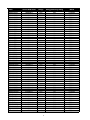
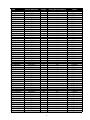
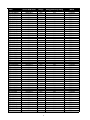
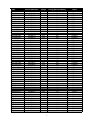
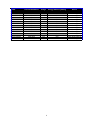
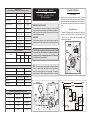
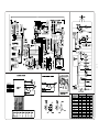
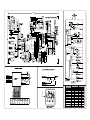
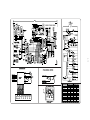
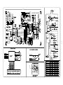
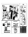
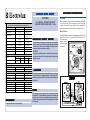
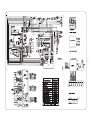
Product Information
and Technical Guide
Side by Side and Top Mount Refrigerators
July 2003 - December 2003
®
®
5995540384
White-Westinghouse
®
January 2004
TABLE OF CONTENTS
Safe Servicing Practices ------------------------------------------------------------------------------------------ 2
Service Data Sheet, Refrigerant Charge & Energy Efficiency Rating Indexes ------------------- 3 - 9
Troubleshooting Guide --------------------------------------------------------------------------------------------- 10 - 14
Appendix A - Service Data Sheets
240379010 --------------------------------------------------------------------------------------------------------- A1 - A2
240379011 --------------------------------------------------------------------------------------------------------- A3 - A4
240379012 --------------------------------------------------------------------------------------------------------- A5 - A6
240379013 --------------------------------------------------------------------------------------------------------- A7 - A8
240389610 --------------------------------------------------------------------------------------------------------- A9 - A10
240389611 --------------------------------------------------------------------------------------------------------- A11 - A12
240389612 --------------------------------------------------------------------------------------------------------- A13 - A14
240389613 --------------------------------------------------------------------------------------------------------- A15 - A16
240389614 --------------------------------------------------------------------------------------------------------- A17 - A18
240389015 --------------------------------------------------------------------------------------------------------- A19 - A20
241532600 --------------------------------------------------------------------------------------------------------- A21- A22
1
SAFE SERVICING PRACTICES - ALL APPLIANCES
To avoid personal injury and/or property damage, it is important that Safe Servicing
Practices be observed. The following are some limited examples of safe practices:
1. DO NOT attempt a product repair if you have any doubts as to your ability to
complete it in a safe and satisfactory manner.
2. Before servicing or moving an appliance:
• Remove the power cord from the electrical outlet, trip the circuit breaker to the
OFF position, or remove the fuse.
• Turn off the gas supply.
• Turn off the water supply.
3. Never interfere with the proper operation of any safety device.
4. USE ONLY REPLACEMENT PARTS CATALOGED FOR THIS APPLIANCE.
SUBSTITUTIONS MAY DEFEAT COMPLIANCE WITH SAFETY
STANDARDS SET FOR HOME APPLIANCES.
5. GROUNDING: The standard color coding for safety ground wires is GREEN, or
GREEN with YELLOW STRIPES. Ground leads are not to be used as current
carrying conductors. It is EXTREMELY important that the service technician
reestablish all safety grounds prior to completion of service. Failure to do so will
create a hazard.
6. Prior to returning the product to service, ensure that:
• All electrical connections are correct and secure
• All electrical leads are properly dressed and secured away from sharp edges,
high-temperature components, and moving parts
• All non-insulated electrical terminals, connectors, heaters, etc. are adequately
spaced away from all metal parts and panels
• All safety grounds (both internal and external) are correctly and securely
connected
• All panels are properly and securely reassembled
ATTENTION!!!
This service manual is intended for use by persons having electrical and mechnical
training and a level of knowledge of these subjects generally considered acceptable in the
appliance repair trade. Electrolux Home Products, Inc. cannot be responsible, nor assume
any liability, for injury or damage of any kind arising from the use of this manual.
© 2004 Electrolux Home Products, Inc.
2
Model
E23CS75DSS0
FRS23BH5CQ1
FRS23BH5CW1
FRS23BH6CB1
FRS23BH6CS1
FRS23F4CB2
FRS23F4CB3
FRS23F4CQ2
FRS23F4CQ3
FRS23F4CW2
FRS23F4CW3
FRS23H5ASB8
FRS23H7CB1
FRS23H7CQ1
FRS23H7CSB1
FRS23H7CW1
FRS23KF5CB2
FRS23KF5CB3
FRS23KF5CQ2
FRS23KF5CQ3
FRS23KF5CS0
FRS23KF5CW2
FRS23KF5CW3
FRS23KF6CB1
FRS23KF6CQ1
FRS23KF6CW1
FRS23R4CB2
FRS23R4CB3
FRS23R4CQ2
FRS23R4CQ3
FRS23R4CW2
FRS23R4CW3
FRS23W3AQ9
FRS23W3AW9
FRS26BH5CQ2
FRS26BH5CW2
FRS26BH6CB1
FRS26BH6CB2
FRS26BH6CB3
FRS26BH6CS3
FRS26BH6CW2
FRS26BH6CW3
FRS26F4CB1
FRS26F4CQ1
FRS26F4CW1
FRS26H5ASB6
FRS26H5ASB7
FRS26H5ASB8
FRS26H7CB1
FRS26H7CB2
FRS26H7CB3
FRS26H7CQ1
Service Data Sheet
Charge
Energy Efficiency Rating
Brand
241532600
240389613
240389613
240389613
240389613
240389612
240389613
240389612
240389613
240389612
240389613
240389613
240389613
240389613
240389613
240389613
240389612
240389613
240389612
240389613
240389613
240389612
240389613
240389613
240389613
240389613
240389612
240389613
240389612
240389613
240389612
240389613
240389612
240389612
240389613
240389613
240389613
240389613
240389614
240389614
240389613
240389613
240389613
240389613
240389613
240389610
240389613
240389613
240389613
240389613
240389614
240389613
5.75
5
5
5
5
5
5
5
5
5
5
5
5
5
5
5
5
5
5
5
5
5
5
5
5
5
5
5
5
5
5
5
5
5
5.25
5.25
5.25
5.25
5.25
5.25
5.25
5.25
5.25
5.25
5.25
5.25
5.25
5.25
5.25
5.25
5.25
5.25
687
617
617
617
617
686
686
686
686
686
686
617
617
617
617
617
686
686
686
686
686
686
686
617
617
617
686
686
686
686
686
686
686
686
654
654
654
654
654
654
654
654
727
727
727
654
654
654
654
654
654
654
Electrolux
Frigidaire
Frigidaire
Frigidaire
Frigidaire
Frigidaire
Frigidaire
Frigidaire
Frigidaire
Frigidaire
Frigidaire
Frigidaire
Frigidaire
Frigidaire
Frigidaire
Frigidaire
Frigidaire
Frigidaire
Frigidaire
Frigidaire
Frigidaire
Frigidaire
Frigidaire
Frigidaire
Frigidaire
Frigidaire
Frigidaire
Frigidaire
Frigidaire
Frigidaire
Frigidaire
Frigidaire
Frigidaire
Frigidaire
Frigidaire
Frigidaire
Frigidaire
Frigidaire
Frigidaire
Frigidaire
Frigidaire
Frigidaire
Frigidaire
Frigidaire
Frigidaire
Frigidaire
Frigidaire
Frigidaire
Frigidaire
Frigidaire
Frigidaire
Frigidaire
3
Model
FRS26H7CQ2
FRS26H7CQ3
FRS26H7CSB1
FRS26H7CSB2
FRS26H7CSB3
FRS26H7CW1
FRS26H7CW2
FRS26H7CW3
FRS26HF6BB3
FRS26HF6BB4
FRS26HF6BQ3
FRS26HF6BQ4
FRS26HF6BW3
FRS26HF6BW4
FRS26HF7BB3
FRS26HF7BB4
FRS26HF7BQ3
FRS26HF7BQ4
FRS26HF7BW3
FRS26HF7BW4
FRS26KF5CB1
FRS26KF5CQ1
FRS26KF5CW1
FRS26KF6CB1
FRS26KF6CB2
FRS26KF6CB3
FRS26KF6CQ1
FRS26KF6CQ2
FRS26KF6CQ3
FRS26KF6CW1
FRS26KF6CW2
FRS26KF6CW3
FRS26KR4CB1
FRS26KR4CQ1
FRS26KR4CW1
FRS26LF8CB0
FRS26LF8CQ0
FRS26LF8CS0
FRS26LF8CW0
FRS26LR5CB0
FRS26LR5CQ0
FRS26LR5CW0
FRS26R2AQ6
FRS26R2AW6
FRS26R4CB1
FRS26R4CQ1
FRS26R4CW1
FRS26RBCW1
FRS26RLECS0
FRS26W2AW7
FRS26W2BSB5
FRT14A2AW3
Service Data Sheet
Charge
Energy Efficiency Rating
Brand
240389613
240389614
240389613
240389613
240389614
240389613
240389613
240389614
240389613
240389613
240389613
240389613
240389613
240389613
240389613
240389613
240389613
240389613
240389613
240389613
240389613
240389613
240389613
240389611
240389613
240389614
240389611
240389613
240389614
240389611
240389613
240389614
240389613
240389613
240389613
240389614
240389614
240389614
240389614
240389615
240389615
240389615
240389613
240389613
240389613
240389613
240389613
240389613
240389613
240389613
240389613
240379011
5.25
5.25
5.25
5.25
5.25
5.25
5.25
5.25
5.25
5.25
5.25
5.25
5.25
5.25
5.25
5.25
5.25
5.25
5.25
5.25
5.25
5.25
5.25
5.25
5.25
5.25
5.25
5.25
5.25
5.25
5.25
5.25
5.25
5.25
5.25
5.25
5.25
5.25
5.25
5.25
5.25
5.25
5.25
5.25
5.25
5.25
5.25
5.25
5.25
5.25
5.25
4.5
654
654
654
654
654
654
654
654
654
654
654
654
654
654
654
654
654
654
654
654
727
727
727
654
654
654
654
654
654
654
654
654
727
727
727
654
617
654
654
727
727
727
727
727
727
727
727
727
727
727
727
440
Frigidaire
Frigidaire
Frigidaire
Frigidaire
Frigidaire
Frigidaire
Frigidaire
Frigidaire
Frigidaire
Frigidaire
Frigidaire
Frigidaire
Frigidaire
Frigidaire
Frigidaire
Frigidaire
Frigidaire
Frigidaire
Frigidaire
Frigidaire
Frigidaire
Frigidaire
Frigidaire
Frigidaire
Frigidaire
Frigidaire
Frigidaire
Frigidaire
Frigidaire
Frigidaire
Frigidaire
Frigidaire
Frigidaire
Frigidaire
Frigidaire
Frigidaire
Frigidaire
Frigidaire
Frigidaire
Frigidaire
Frigidaire
Frigidaire
Frigidaire
Frigidaire
Frigidaire
Frigidaire
Frigidaire
Frigidaire
Frigidaire
Frigidaire
Frigidaire
Frigidaire
4
Model
FRT14A2AZ3
FRT15B1BW1
FRT15B3AQ4
FRT15B3AT4
FRT15B3AW4
FRT15B3AZ4
FRT15G4BQ2
FRT15G4BW2
FRT15G5CSB1
FRT15G5CSK1
FRT15HB3AQ5
FRT15HB3AW5
FRT15HB3AZ5
FRT17A2AQ3
FRT17A2AW3
FRT17A2AZ3
FRT17B3AQ4
FRT17B3AT4
FRT17B3AW4
FRT17B3AZ4
FRT17G4BD2
FRT17G4BQ2
FRT17G4BW2
FRT17HB3CW1
FRT18B1BW2
FRT18B4AQ8
FRT18B4AT8
FRT18B4AW8
FRT18B4AZ8
FRT18B5AB9
FRT18B5AW9
FRT18B5AWA
FRT18B6CB3
FRT18G4AQB
FRT18G4AWB
FRT18G5AQA
FRT18G5AWA
FRT18G7CW2
FRT18H6CSB2
FRT18H6CSK2
FRT18H7CW2
FRT18HS6AWA
FRT18IB4AW8
FRT18IG4AQ8
FRT18IG4AT8
FRT18IG4AW8
FRT18IG4AZ8
FRT18KB2CW2
FRT18KG3CW2
FRT18LN5BQ3
FRT18LN5BQ5
FRT18LN5BW3
Service Data Sheet
Charge
Energy Efficiency Rating
Brand
240379011
240379011
240379011
240379011
240379011
240379011
240379011
240379011
240379011
240379011
240379011
240379011
240379011
240379011
240379011
240379011
240379011
240379011
240379011
240379011
240379011
240379011
240379011
240379010
240379011
240379011
240379011
240379011
240379011
240379012
240379012
4.5
4.5
4.5
4.5
4.5
4.5
4.5
4.5
4.5
4.5
4.25
4.25
4.25
4.5
4.5
4.5
4.5
4.5
4.5
4.5
4.5
4.5
4.5
4.5
4.5
4.5
4.5
4.5
4.5
4.25
4.25
4.5
4.25
4.5
4.5
4.25
4.25
4.5
4.25
4.25
4.25
4.25
4.5
4.5
4.5
4.5
4.5
4.5
4.5
4.25
4.25
4.25
440
443
443
443
443
443
443
443
443
443
398
398
398
460
460
460
460
460
460
460
460
460
460
460
479
479
479
479
479
479
479
479
479
479
479
479
479
479
431
431
431
431
479
479
479
479
479
479
479
479
479
479
Frigidaire
Frigidaire
Frigidaire
Frigidaire
Frigidaire
Frigidaire
Frigidaire
Frigidaire
Frigidaire
Frigidaire
Frigidaire
Frigidaire
Frigidaire
Frigidaire
Frigidaire
Frigidaire
Frigidaire
Frigidaire
Frigidaire
Frigidaire
Frigidaire
Frigidaire
Frigidaire
Frigidaire
Frigidaire
Frigidaire
Frigidaire
Frigidaire
Frigidaire
Frigidaire
Frigidaire
Frigidaire
Frigidaire
Frigidaire
Frigidaire
Frigidaire
Frigidaire
Frigidaire
Frigidaire
Frigidaire
Frigidaire
Frigidaire
Frigidaire
Frigidaire
Frigidaire
Frigidaire
Frigidaire
Frigidaire
Frigidaire
Frigidaire
Frigidaire
Frigidaire
240379012
240379011
240379011
240379012
240379012
240379011
240379011
240379011
240379011
240379011
240379011
240379011
240379011
240379011
240379011
240379011
240379011
240379012
240379012
240379012
5
Model
FRT18LN5BW5
FRT18LR7AQA
FRT18LR7AWA
FRT18P6BSB2
FRT18P6BSK2
FRT18P6CQ3
FRT18P6CQ5
FRT21BH8CB1
FRT21BH8CS1
FRT21BH8CW1
FRT21C5AQ7
FRT21C5AQ8
FRT21C5AW7
FRT21C5AW8
FRT21FG3CQ1
FRT21FG3CQ2
FRT21FG3CW1
FRT21FG3CW2
FRT21FG4CQ2
FRT21FG4CW2
FRT21H7ASB4
FRT21H7ASK3
FRT21H8CB1
FRT21H8CQ1
FRT21H8CSB1
FRT21H8CSK1
FRT21H8CW1
FRT21HR6AB5
FRT21HR6AQ5
FRT21HR6AW5
FRT21IS6BB3
FRT21IS6BB4
FRT21IS6BQ3
FRT21IS6BQ4
FRT21IS6BW3
FRT21IS6BW4
FRT21KG3CQ2
FRT21KG3CW1
FRT21KG3CW2
FRT21LR7AB8
FRT21LR7AW8
FRT21P5AB8
FRT21P5AB9
FRT21P5AQ8
FRT21P5AQ9
FRT21P5AW8
FRT21P5AW9
FRT21P6CQ1
FRT21P6CQ2
FRT21P6CSB1
FRT21P6CSB2
FRT21P6CSK1
Service Data Sheet
Charge
Energy Efficiency Rating
Brand
240379012
240379011
240379011
240379011
240379011
240379012
240379012
240379012
240379012
240379012
240379012
240379012
240379012
240379012
240379012
240379012
240379012
240379012
240379012
240379012
240379012
240379012
240379012
240379012
240379012
240379012
240379012
240379013
240379013
240379013
240379012
240379012
240379012
240379012
240379012
240379012
240379012
240379012
240379012
240379012
240379012
240379012
240379012
240379012
240379012
240379012
240379012
240379012
240379012
240379012
240379012
240379012
4.25
4.25
4.25
4.25
4.25
4.25
4.25
4.25
4.25
4.25
4.25
4.25
4.25
4.25
4.25
4.25
4.25
4.25
4.25
4.25
4.25
4.25
4.25
4.25
4.25
4.25
4.25
4.25
4.25
4.25
4.25
4.25
4.25
4.25
4.25
4.25
4.25
4.25
4.25
4.25
4.25
4.25
4.25
4.25
4.25
4.25
4.25
4.25
4.25
4.25
4.25
4.25
479
431
431
431
431
479
479
458
458
458
509
509
509
509
509
509
509
509
509
509
458
458
458
458
458
458
458
458
458
458
509
509
509
509
509
509
509
509
509
458
458
509
509
509
509
509
509
509
509
509
509
509
Frigidaire
Frigidaire
Frigidaire
Frigidaire
Frigidaire
Frigidaire
Frigidaire
Frigidaire
Frigidaire
Frigidaire
Frigidaire
Frigidaire
Frigidaire
Frigidaire
Frigidaire
Frigidaire
Frigidaire
Frigidaire
Frigidaire
Frigidaire
Frigidaire
Frigidaire
Frigidaire
Frigidaire
Frigidaire
Frigidaire
Frigidaire
Frigidaire
Frigidaire
Frigidaire
Frigidaire
Frigidaire
Frigidaire
Frigidaire
Frigidaire
Frigidaire
Frigidaire
Frigidaire
Frigidaire
Frigidaire
Frigidaire
Frigidaire
Frigidaire
Frigidaire
Frigidaire
Frigidaire
Frigidaire
Frigidaire
Frigidaire
Frigidaire
Frigidaire
Frigidaire
6
Model
FRT21P6CSK2
FRT21P6CW1
FRT21P6CW2
FRT21S6AB6
FRT21S6AB7
FRT21S6AQ7
FRT21S6AW6
FRT21S6AW7
GLHS237ZCB1
GLHS237ZCQ1
GLHS237ZCW1
GLHS269ZCB2
GLHS269ZCB3
GLHS269ZCQ2
GLHS269ZCQ3
GLHS269ZCW2
GLHS269ZCW3
GLRS237ZCB2
GLRS237ZCQ2
GLRS237ZCW2
GLRS267ZCB1
GLRS267ZCQ1
GLRS267ZCW1
GLRT184TCB3
GLRT184TCB5
GLRT184TCQ3
GLRT184TCQ5
GLRT184TCW3
GLRT184TCW5
GLRT214TCB1
GLRT214TCB2
GLRT214TCQ1
GLRT214TCQ2
GLRT214TCW1
GLRT214TCW2
GRS23R4CQ2
GRS23R4CW2
GRS23R4CW3
GRS26R4CQ0
GRS26R4CQ1
GRS26R4CW0
GRS26R4CW1
GRT15B3BW2
GRT17B3BQ2
GRT17B3BW2
GRT17G4BQ2
GRT17G4BW2
GRT18C6AQ9
GRT18C6AW7
GRT18C6AW9
GRT18S6AW7
GRT18S6AW9
Service Data Sheet
Charge
Energy Efficiency Rating
Brand
240379012
240379012
240379012
240379012
240379012
240379012
240379012
240379012
240389613
240389613
240389613
240389613
240389614
240389613
240389614
240389613
240389614
240389612
240389612
240389612
240389613
240389613
240389613
240379012
240379012
240379012
240379012
240379012
240379012
240379012
240379012
240379012
240379012
240379012
240379012
240379012
240379012
240379013
240389610
240389613
240389610
240389613
240379011
240379011
240379011
240379011
240379011
240379012
240379012
240379012
240379012
240379012
4.25
4.25
4.25
4.25
4.25
4.25
4.25
4.25
5
5
5
5.25
5.25
5.25
5.25
5.25
5.25
5
5
5
5.25
5.25
5.25
4.25
4.25
4.25
4.25
4.25
4.25
4.25
4.25
4.25
4.25
4.25
4.25
5
5
5
5.25
5.25
5.25
5.25
4.5
4.5
4.5
4.5
4.5
4.25
4.25
4.25
4.25
4.25
509
509
509
509
509
509
509
509
617
617
617
654
654
654
654
654
654
686
686
686
727
727
727
479
479
479
479
479
479
509
509
509
509
509
509
686
686
686
727
727
727
727
443
443
443
443
443
479
479
479
479
479
Frigidaire
Frigidaire
Frigidaire
Frigidaire
Frigidaire
Frigidaire
Frigidaire
Frigidaire
Frigidaire
Frigidaire
Frigidaire
Frigidaire
Frigidaire
Frigidaire
Frigidaire
Frigidaire
Frigidaire
Frigidaire
Frigidaire
Frigidaire
Frigidaire
Frigidaire
Frigidaire
Frigidaire
Frigidaire
Frigidaire
Frigidaire
Frigidaire
Frigidaire
Frigidaire
Frigidaire
Frigidaire
Frigidaire
Frigidaire
Frigidaire
Gibson
Gibson
Gibson
Gibson
Gibson
Gibson
Gibson
Gibson
Gibson
Gibson
Gibson
Gibson
Gibson
Gibson
Gibson
Gibson
Gibson
7
Model
GRT21G3CQ2
GRT21G3CW2
GRT21S6CQ2
GRT21S6CW1
GRT21S6CW2
GS18HTZCQ2
GS18HTZCSB2
GS18HTZCW2
GS21HTZCB0
GS21HTZCB1
GS21HTZCC0
GS21HTZCC1
GS21HTZCK1
GS21HTZCQ0
GS21HTZCQ1
GS21HTZCW1
GS23HSZCB1
GS23HSZCQ1
GS23HSZCW1
GS26HSZCB3
GS26HSZCC1
GS26HSZCC2
GS26HSZCC3
GS26HSZCC4
GS26HSZCQ1
GS26HSZCQ2
GS26HSZCQ3
GS26HSZCW2
GS26HSZCW3
PLHS237ZCB1
PLHS239ZCB1
PLHS267ZCB1
PLHS267ZCB2
PLHS268ZCB2
PLHS268ZCB3
PLHS268ZCB4
PLHS269ZCB1
PLHS269ZCB2
PLHT189CSB2
PLHT189CSK2
PLHT219TCB3
PLHT219TCK2
PLHT219TCK3
WRS23MF5AS9
WRS23MW3AQ8
WRS23MW3AW7
WRS23MW3AW8
WRS23W0AW8
WRS23W0AW9
WRS26MF5AS8
WRT15MG4BQ0
WRT15MG4BW0
Service Data Sheet
Charge
Energy Efficiency Rating
Brand
240379012
240379012
240379012
240379012
240379012
240379011
240379011
240379011
240379010
240379010
240379010
240379010
240379010
240379010
240379010
240379010
240389613
240379013
240389613
240389614
240389613
240389613
240389614
240389614
240389613
240389613
240389614
240389613
240389614
240389613
240389613
240389613
240389613
240389610
240389613
240389613
240389613
240389613
240379011
240379011
240379012
240379010
240379012
240389615
240389613
240389612
240389613
240389612
240389615
240389613
240379010
240379010
4.25
4.25
4.25
4.25
4.25
4.25
4.25
4.25
4.25
4.25
4.25
4.25
4.25
4.25
4.25
4.25
5
5
5
5.25
5.25
5.25
5.25
5.25
5.25
5.25
5.25
5.25
5.25
5
5
5.25
5.25
5.25
5.25
5.25
5.25
5.25
4.25
4.25
4.25
4.25
4.25
5
5
5
5
5
5
5.25
4.25
4.25
509
509
509
509
509
431
431
431
458
458
458
458
458
458
458
458
617
617
617
654
654
654
654
654
654
654
654
654
654
617
617
654
654
654
654
654
654
654
431
431
458
458
458
686
686
686
686
686
686
727
443
443
Gibson
Gibson
Gibson
Gibson
Gibson
Gibson
Gibson
Gibson
Gibson
Gibson
Gibson
Gibson
Gibson
Gibson
Gibson
Gibson
Gibson
Gibson
Gibson
Gibson
Gibson
Gibson
Gibson
Gibson
Gibson
Gibson
Gibson
Gibson
Gibson
Frigidaire
Frigidaire
Frigidaire
Frigidaire
Frigidaire
Frigidaire
Frigidaire
Frigidaire
Frigidaire
Frigidaire
Frigidaire
Frigidaire
Frigidaire
Frigidaire
White Westinghouse
White Westinghouse
White Westinghouse
White Westinghouse
White Westinghouse
White Westinghouse
White Westinghouse
White Westinghouse
White Westinghouse
8
Model
W RT15MG4BW1
W RT17MG4BQ0
W RT17MG4BW0
W RT17MG4BW1
W RT18A0AW 8
W RT18MP5AQ8
W RT18MP5AQA
W RT18MP5AQB
W RT18MP5AW8
W RT18MP5AWB
W RT21MG3AQ4
W RT21MG3AQ5
W RT21MG3AW5
W RT21S4AW 4
W RT21S4AW 5
Service Data Sheet
Charge
Energy Efficiency Rating
240379011
240379010
240379010
240379011
240379011
240379011
240379012
240379012
240379011
240379012
240379012
240379012
240379012
240379012
240379012
4.25
4.25
4.25
4.25
4.5
4.25
4.25
4.25
4.25
4.25
4.25
4.25
4.25
4.25
4.25
443
460
460
460
479
479
479
479
479
479
509
509
509
509
509
9
Brand
W hite
W hite
W hite
W hite
W hite
W hite
W hite
W hite
W hite
W hite
W hite
W hite
W hite
W hite
W hite
Westinghouse
Westinghouse
Westinghouse
Westinghouse
Westinghouse
Westinghouse
Westinghouse
Westinghouse
Westinghouse
Westinghouse
Westinghouse
Westinghouse
Westinghouse
Westinghouse
Westinghouse
TROUBLESHOOTING
GUIDE
PROBLEM
Compressor will not run.
Compressor runs but does not cool.
CAUSE
No voltage at wall receptacle.
Check circuit breaker, fuse or GFCI
(Ground Fault Circuit Interruptor - It
is not recommended to connect
your refrigerator to a GFCI.)
Service cord defective or unplugged
at wall receptacle.
Check service cord.
Low voltage causing compressor to
cycle on overload.
Voltage fluctuation should not
exceed ± 10% of 115 vac (104-127)
Control thermostat knob in OFF
position.
Turn control thermostat knob to ON
position.
Inoperative control thermostat.
Replace control thermostat
Compressor stuck.
Replace compressor.
Compressor windings open.
Replace compressor.
Defrost timer stuck in defrost mode.
Replace defrost timer. (if equipped)
ADC (Adaptive Defrost Control) not
turning on compressor after defrost.
Replace ADC.
Compressor overload stuck open.
Replace compressor overload. (if
equipped – compressor starter relay
& overload may be plugged into
each other)
Relay lead loose.
Repair or replace lead.
Relay loose or inoperative.
Repair or replace relay. (if equipped)
Service cord pulled out of harness.
Repair connection.
Faulty cabinet wiring.
Repair wiring.
System out of refrigerant.
Check for leaks. *
Compressor not pumping.
Replace compressor. *
Restricted filter drier.
Replace filter drier. *
Restricted capillary tube.
Replace heat exchanger
evaporator assembly.
Moisture in system.
See NOTE. *
* NOTE:
•
•
•
•
•
SOLUTION
Repair or replace component that is leaking.
Replace the compressor if the system is contaminated.
Blow out remaining part of system with dry Nitrogen.
Pump down and recharge per listing on product serial label.
Always replace filter drier when repairing sealed system.
10
and
PROBLEM
Compressor short cycles.
Compressor runs too much.
Noisy.
*
CAUSE
SOLUTION
Erratic control thermostat.
Replace control thermostat.
Faulty relay.
Replace relay or starter.
Restricted air flow over condenser.
Ensure air flow is unobstructed over
condenser.
Low voltage … fluctuation exceeds ±
10% of 115 vac (104-127).
Call qualified electrician.
Compressor draws excessive watts.
Replace compressor.
Inoperative condenser fan motor.
Replace condenser fan motor.
Control thermostat is erratic or not
properly set.
Replace control thermostat or reset to
normal position.
Refrigerator exposed to high heat.
(110° or higher)
Move refrigerator to cooler location.
High room temperature.
(110° F or higher)
Advise customer not to install
refrigerator where temperature will rise
above 110°F because compressor will
not maintain proper temperatures.
Low pumping capacity compressor.
Replace compressor.
Door gaskets not sealing.
Adjust doors or replace door gaskets.
System undercharged.
Check for leaks. *
System overcharged.
Charge per listing on product serial
plate. *
Interior light stays on.
Check
door
adjustment.
Contaminants in system.
Flush out system. Replace filter drier,
evacuate, and recharge. *
Capillary tube kinked or partially
restricted.
Replace
heat
exchanger
evaporator assembly. *
Filter drier partially restricted.
Replace filter drier. *
Refrigerator
and/or
freezer
compartment overloaded … poor air
circulation
Advise customer.
Restricted air flow over condenser.
Ensure air flow is unobstructed over
condenser.
Condenser fan motor is inoperative.
(Forced air condenser models only)
Replace condenser fan motor.
Tubing vibrates.
Adjust tubing.
Internal compressor noise.
Replace compressor.
Loose parts.
Check shelving.
Compressor operating at high head
pressure due to restricted air flow
over condenser.
Ensure air flow is unobstructed over
condenser.
See NOTE at bottom of page 10
11
switch
and
door
and
PROBLEM
Freezer compartment too warm.
Fig. A
Freezer compartment too cold.
* See NOTE at bottom of page 10
CAUSE
SOLUTION
Inoperative evaporator fan motor.
Check wiring and evaporator fan motor.
(Check ADC on Side-by-Sides.)
Improperly positioned fan blade.
Position fan blade properly. See Figure
A.
Evaporated frosted up.
Check
defrost
system,
adjustments, and door gaskets.
Inoperative condenser fan motor.
(Forced air condenser models
only)
Replace condenser fan motor.
Restricted air flow over condenser
– On static condensers, be sure
you have 1” between condenser
and wall, and 3” over top, or 1
side of condenser is clear.
Clean
only.)
Freezer compartment overloaded
– poor air circulation.
Advise customer.
Low room temperature. (60° or
lower, 55° for models with Service
Data Sheet numbers 24038960015 and 240379001-13.)
Advise
customer
not
to
install
refrigerator where temperature will drop
below 60°F. Compressor will not
maintain proper temperatures.
Freezer
or
refrigerator
compartment doors left open.
Advise customer.
Control
thermostat
calibration.
Replace control thermostat.
out
of
condenser.
(Dynamic
door
models
Door gaskets not sealing.
Adjust doors or replace door gaskets.
Control thermostat capillary tube
improperly positioned.
Reposition
element.
Shortage of refrigerant.
Check for leaks. *
Restricted filter drier or capillary
tube.
Check for leaks and burnt compressor
windings. *
Evaporator fan motor covered in
ice.
Check seal around ice maker fill spout.
Check seal between evaporator cover
and liner. (Side-by-sides only)
Inoperative cold control. (Top
mount-No Frost or Side-by-Side
freezer cold control)
Replace cold control.
Freezer compartment inlet air
duct is loose or restricted. Door is
loose.
Re-install air duct or remove obstruction
from inlet air duct. Adjust door.
Food compartment air return duct
blocked (Top Mount only)
If foam block is frozen, replace block. If
duct is blocked, remove obstruction.
Diffuser (foam block) in top of
food compartment is broken.
(Foam block located in control
housing for models with Service
5 Sheets 240389600-15 and
Data
240379001-13.)
Replace diffuser. (Top Mount only)
Freezer compartment cold control
installed
incorrectly.
(Side-by-Sides
only)
12
temperature
sensing
PROBLEM
Refrigerator
warm.
compartment
too
Refrigerator compartment too cold.
*
CAUSE
SOLUTION
Inoperative evaporator fan motor.
Check wiring and evaporator fan motor.
(Check ADC on Side-by-Sides.)
Improperly positioned fan blade.
Position fan blade properly. See page
12, Figure A.
Evaporated frosted up.
Check
defrost
system,
adjustments, and door gaskets.
Refrigerator
compartment
overloaded – poor air circulation.
Advise customer.
Low room temperature. (60° or
lower, 55° for models with Service
Data Sheet numbers 24038960015 and 240379001-13.)
Advise
customer
not
to
install
refrigerator where temperature will drop
below 60°F. Compressor will not
maintain proper temperatures.
Freezer
or
refrigerator
compartment doors left open.
Advise customer.
Damper control out of calibration
or not opening.
Replace damper control.
Shortage of refrigerant.
Check for leaks. *
Restricted filter drier or capillary
tube.
Check for leaks and burnt compressor
windings. *
Refrigerator compartment inlet air
duct loose or restricted. Door is
loose.
Re-install air duct or remove obstruction
from air duct. Adjust door.
Freezer compartment return air
duct restricted.
Remove obstruction from return air duct.
Control thermostat knob set at too
warm a position.
Set control knob to a colder position.
Inoperative
or
erratic
refrigerator/freezer compartment
door switch.
Replace door switch.
Freezer compartment inlet air
duct is loose or restricted. Door is
loose.
Re-install air duct or remove obstruction
from inlet air duct. Adjust door.
Food compartment air return duct
blocked (Top Mount only)
If foam block is frozen, replace block. If
duct is blocked, remove obstruction.
Inoperative cold control.
Replace cold control.
Refrigerator compartment inlet air
duct loose or restricted. Door is
loose.
Re-install air duct or remove obstruction
from air duct. Adjust door.
Diffuser (foam block) in top of
food compartment is broken.
(Foam blocked located in control
housing for models with Service
Data Sheet numbers 24038960015 and 240379001-13.)
Replace diffuser. (Top Mounts only)
See NOTE at bottom of page 10.
13
door
PROBLEM
Refrigerator compartment too cold.
(Continued)
CAUSE
SOLUTION
Inoperative cold control.
Replace cold control.
Refrigerator compartment inlet air
duct loose or restricted. Door is
loose.
Re-install air duct or remove obstruction
from air duct. Adjust door.
Diffuser (foam block) in top of
food compartment is broken.
(Foam blocked located in control
housing for models with Service
Data Sheet numbers 24038960015 and 240379001-13.)
Replace diffuser. (Top Mounts only)
Door in damper control not
closing or not closing all the way.
Replace damper control.
Check freezer control bulb for correct
positioning to ensure it is installed
correctly.
Evaporator blocked with ice. (See
Adaptive defrost Control below for
models with Service Data Sheet
numbers
240389600-15
and
240379010-13.)
Frozen drain.
Adaptive Defrost Control (ADC) not
responding correctly.
Cold air blowing into food
compartment with damper door
closed all the way.
Check foam seal between damper
housing and cabinet liner. Check to see
that the control box is mounted flush
against the cabinet liner.
Inoperative defrost timer.
Check wiring. Repair or replace defrost
timer.
Defrost thermostat terminates too
early. Thermostat is open.
Check for correct positioning of defrost
thermostat. Repair or replace.
Refrigerator/Freezer compartment
doors left open.
Advise customer.
Open defrost heater.
Replace heater.
Air leak around ice maker fill tube,
or opening.
Seal with permagum.
Ice maker water line and wiring
harness openings not sealed.
Seal water line and wiring harness
openings.
Drain trough not properly formed.
Ensure drain trough is at 90° angle to
back of freezer and that lip is up on front
and ends.
Divider (foam block) frozen.
Replace divider. Check drain trough.
Faulty ADC board.
Replace ADC board.
Bad wire between ADC, defrost
heater, and limiter.
Check wiring and wiring connectors.
14
PERFORMANCE DATA
NO LOAD AND NO DOOR OPENINGS AT MID-POINT CONTROL SETTING
Type A With Run Capacitor
SERVICE DATA SHEET
65°F (18°C) Ambient
90°F (32°C) Ambient
25 to 35%
45 to 55%
2° to 8°F
-17° to -13°C
0° to 5°F
-18° to -15°C
Refrigerature Temperature
35° to 40°F
2° to 4°C
35° to 40°F
2° to 4°C
Low Side Pressure (cut-in)
8 to 16 psig
55 to 110 kPa
8 to 16 psig
55 to 110 kPa
Low Side Pressure (cut-out)
1 to 4 psig
7 to 28 kPa
1 to 4 psig
7 to 28 kPa
110 to 120 psig
758 to 827 kPa
150 to 175 psig
1034 to 1207 kPa
Wattage (Last 1/3 of cycle)
140 to 185
140 to 185
Amps (Running)
1.1 to 1.6
1.1 to 1.6
115 VAC (127 VAC Max)
115 VAC (127 VAC Max)
Operating Time
Freezer Temperature
High Side Pressure (Last 1/3 of cycle)
Base Voltage
DEFROST SPECIFICATIONS
Cabinet Size
Thermostat
Heater
Cut-out
Watts
Ohms
18' & 21'
25°F
-4°C
47°F
8°C
375
35
14', 15' & 17'
25°F
-4°C
47°F
8°C
325
41
Mechanical Timer - Defrost 30 Minutes Every 10 Hours of Compressor Run Time
Electronic Timer (ADC) Defrost Up To 24 Minutes Every 6 - 72 Hours of Compressor Run Time
CONDENSER FAN MOTOR
Watts
RPM
Amps
2.3
1100 CW Opposite Shaft
.15 Running
Test Cycling
P/N: 240379010
IMPORTANT SAFETY NOTICE
The information provided herein is designed to assist qualified
repair personnel only. Untrained persons should not attempt to
make repairs due to the possibility of electrical shock. Disconnect
power cord before servicing.
IMPORTANT
If any green grounding wires are moved during servicing, they
must be returned to their original position and properly secured.
Remove cover by inserting screwdriver in notch at bottom
and prying cover from housing. Use screwdriver to rotate motor
gear counterclockwise until holding switch circuit is completed.
All components of ice maker should function to complete the
cycle.
Water Fill Volume
The water fill adjustment screw will change the fill time. One
full turn is equal to 20cc (.68 oz.). The correct fill is 102 to
130cc (3.4 to 4.3 oz.). When a water valve is replaced, the fill
volume must be checked.
CAUTION: All electrical parts and wiring must be shielded
from torch flame. Do not allow torch to contact insulation;
it will char at 200°F and flash ignite (burn) at 500°F. Excessive
heat will distort the plastic liner.
A-1
Cut-in
STANDARD - AUTOMATIC
DEFROST TOP FREEZER
MODELS
(R134a)
ICE MAKER INFORMATION
NOTE: This product comes equipped with an Electronic Defrost
Control. To initiate defrost, depress the fresh food light switch 5
times in 6 seconds (light bulb must be working). To terminate
defrost, depress the fresh food light switch 5 times in 6 seconds.
ICE MAKER SPECIFICATIONS
ICE MAKER
Heater Wattage
P-3
165
THERMAL
CUT-OUT
Yellow
Ground
Water Valve
3
Black
Line
4
Lt. Blue
Neutral
RED
HOLD
SWITCH
ICE MAKER
Connects to:
C
YEL
NO
RED
NC
THERMOSTAT
NO
BLU
BLK
C
GRN / YEL
2
Green/Yellow
MOTOR
MOLD HEATER
165 WATTS
GRN / YEL
C
P-1
MOLD
MOUNTING
PLATE
P-4
NC
NO
SHUT-OFF
SWITCH
NC
LT. BLU
WATER FILL
SWITCH
P-2
WATER VALVE
1
Wire Color
BLK
ICE MAKER CONNECTOR PLUG CONNECTIONS
Wire Number
ICE MAKER
BRN
BLK
YEL
Closes at 15°F (-9°C)
NEUTRAL
POWER
YEL
Opens at 48°F (9°C)
LINE
RED
60 Her tz
BLK
Thermostat
115 VAC (127 VAC Max)
ICE MAKER
Electrical
Pictorial Schematic
Ladder Schematic
A-2
Compressor Wiring
SERVICE PARTS
Compressor Kit *
Starter/PTC *
Run Capacitor *
Temperature Control
Timer (if applicable)
ADC (if applicable)
Defrost Heater Kit
Defrost Thermostat Kit
Evaporator Fan Motor
Condenser Fan Motor
15 & 17 CUBIC FOOT
STATIC
DYNAMIC
E-STAR
5303918264 5303918264 5303918280
218721120 218721120 218721119
218909901 218909901 218909901
5304421256 5304421256 5304421256
215846606 215846606
N/A
N/A
N/A
240545401
5303918203 5303918203 5303918203
5303918202 5303918202 5303918202
240369701 240369701 240369701
N/A
240397101 240397101
18 CUBIC FOOT
STATIC
DYNAMIC
E-STAR
5303918264 5303918264 5303918280
218721120 218721120 218721119
218909901 218909901 218909901
5304421256 5304421256 5304421256
215846606 215846606
N/A
N/A
N/A
240545401
5303918208 5303918208 5303918208
5303918202 5303918202 5303918202
240369701 240369701 240369701
N/A
240397101 240397101
* Typical compressor kit includes compressor, electrical components, and filter-drier
21 CUBIC FOOT
DYNAMIC
E-STAR
5303918264 5303918251
218721120 218721119
218909901 216787800
5304421256 5304421256
215846606
N/A
N/A
240545401
5303918247 5303918247
5303918202 5303918202
240369701 240369701
240334001 240334001
PERFORMANCE DATA
NO LOAD AND NO DOOR OPENINGS AT MID-POINT CONTROL SETTING
Type A With Run Capacitor
SERVICE DATA SHEET
65°F (18°C) Ambient
90°F (32°C) Ambient
25 to 35%
45 to 55%
2° to 8°F
-17° to -13°C
0° to 5°F
-18° to -15°C
Refrigerature Temperature
35° to 40°F
2° to 4°C
35° to 40°F
2° to 4°C
Low Side Pressure (cut-in)
8 to 16 psig
55 to 110 kPa
8 to 16 psig
55 to 110 kPa
Low Side Pressure (cut-out)
1 to 4 psig
7 to 28 kPa
1 to 4 psig
7 to 28 kPa
110 to 120 psig
758 to 827 kPa
150 to 175 psig
1034 to 1207 kPa
Wattage (Last 1/3 of cycle)
140 to 185
140 to 185
Amps (Running)
1.1 to 1.6
1.1 to 1.6
115 VAC (127 VAC Max)
115 VAC (127 VAC Max)
Operating Time
Freezer Temperature
High Side Pressure (Last 1/3 of cycle)
Base Voltage
DEFROST SPECIFICATIONS
Cabinet Size
Thermostat
Heater
Cut-out
Watts
Ohms
18' & 21'
25°F
-4°C
47°F
8°C
375
35
14', 15' & 17'
25°F
-4°C
47°F
8°C
325
41
Mechanical Timer - Defrost 30 Minutes Every 10 Hours of Compressor Run Time
Electronic Timer (ADC) Defrost Up To 24 Minutes Every 6 - 72 Hours of Compressor Run Time
CONDENSER FAN MOTOR
Watts
RPM
Amps
2.3
1100 CW Opposite Shaft
.15 Running
Test Cycling
P/N: 240379011
IMPORTANT SAFETY NOTICE
The information provided herein is designed to assist qualified
repair personnel only. Untrained persons should not attempt to
make repairs due to the possibility of electrical shock. Disconnect
power cord before servicing.
IMPORTANT
If any green grounding wires are moved during servicing, they
must be returned to their original position and properly secured.
Remove cover by inserting screwdriver in notch at bottom
and prying cover from housing. Use screwdriver to rotate motor
gear counterclockwise until holding switch circuit is completed.
All components of ice maker should function to complete the
cycle.
Water Fill Volume
The water fill adjustment screw will change the fill time. One
full turn is equal to 20cc (.68 oz.). The correct fill is 102 to
130cc (3.4 to 4.3 oz.). When a water valve is replaced, the fill
volume must be checked.
CAUTION: All electrical parts and wiring must be shielded
from torch flame. Do not allow torch to contact insulation;
it will char at 200°F and flash ignite (burn) at 500°F. Excessive
heat will distort the plastic liner.
A-3
Cut-in
STANDARD - AUTOMATIC
DEFROST TOP FREEZER
MODELS
(R134a)
ICE MAKER INFORMATION
NOTE: This product comes equipped with an Electronic Defrost
Control. To initiate defrost, depress the fresh food light switch 5
times in 6 seconds (light bulb must be working). To terminate
defrost, depress the fresh food light switch 5 times in 6 seconds.
ICE MAKER SPECIFICATIONS
ICE MAKER
Heater Wattage
P-3
165
THERMAL
CUT-OUT
Yellow
Ground
Water Valve
3
Black
Line
4
Lt. Blue
Neutral
RED
HOLD
SWITCH
ICE MAKER
Connects to:
C
YEL
NO
RED
NC
THERMOSTAT
NO
BLU
BLK
C
GRN / YEL
2
Green/Yellow
MOTOR
MOLD HEATER
165 WATTS
GRN / YEL
C
P-1
MOLD
MOUNTING
PLATE
P-4
NC
NO
SHUT-OFF
SWITCH
NC
LT. BLU
WATER FILL
SWITCH
P-2
WATER VALVE
1
Wire Color
BLK
ICE MAKER CONNECTOR PLUG CONNECTIONS
Wire Number
ICE MAKER
BRN
BLK
YEL
Closes at 15°F (-9°C)
NEUTRAL
POWER
YEL
Opens at 48°F (9°C)
LINE
RED
60 Her tz
BLK
Thermostat
115 VAC (127 VAC Max)
ICE MAKER
Electrical
Pictorial Schematic
Ladder Schematic
A-4
NOTE:
_ _ _ _ _ _ DENOTES NOT ON ALL MODELS
COMPRESSOR WIRING
Induction Run Compressor with Relay
SERVICE PARTS
Compressor / Kit *
Starter/PTC *
Run Capacitor *
Relay
Overload
Temperature Control
Timer (if applicable)
ADC (if applicable)
Defrost Heater Kit
Defrost Thermostat Kit
Evaporator Fan Motor
Condenser Fan Motor
15 & 17 CUBIC FOOT
STATIC
DYNAMIC
E-STAR
5303918264 5303918264 5303918295
218721120
218721120
218721120
218909913
218909913
218909912
N/A
N/A
N/A
N/A
N/A
N/A
5304421256 5304421256 5304421256
215846606
215846606
215846606
N/A
N/A
N/A
5303918203 5303918203 5303918203
5303918202 5303918202 5303918202
240369701
240369701
240369701
N/A
240523601
240523601
STATIC
240435705
218721120
218909913
5304433579
5304433578
5304421256
215846606
N/A
5303918208
5303918202
240369701
N/A
18 CUBIC FOOT
DYNAMIC
E-STAR
240435705 5303918295
218721120
218721120
218909913
218909912
5304433579
N/A
5304433578
N/A
5304421256 5304421256
215846606
215846606
N/A
N/A
5303918208 5303918208
5303918202 5303918202
240369701
240369701
240523601
240523601
21 CUBIC FOOT
DYNAMIC
E-STAR
5303918264 5303918295
218721120 218721120
218909913 218909912
N/A
N/A
N/A
N/A
5304421256 5304421256
215846606 215846606
N/A
N/A
5303918247 5303918247
5303918202 5303918202
240369701 240369701
240334001 240334001
PERFORMANCE DATA
NO LOAD AND NO DOOR OPENINGS AT MID-POINT CONTROL SETTING
Type A With Run Capacitor
SERVICE DATA SHEET
65°F (18°C) Ambient
90°F (32°C) Ambient
25 to 35%
45 to 55%
2° to 8°F
-17° to -13°C
0° to 5°F
-18° to -15°C
Refrigerature Temperature
35° to 40°F
2° to 4°C
35° to 40°F
2° to 4°C
Low Side Pressure (cut-in)
8 to 16 psig
55 to 110 kPa
8 to 16 psig
55 to 110 kPa
Low Side Pressure (cut-out)
1 to 4 psig
7 to 28 kPa
1 to 4 psig
7 to 28 kPa
110 to 120 psig
758 to 827 kPa
150 to 175 psig
1034 to 1207 kPa
Wattage (Last 1/3 of cycle)
140 to 185
140 to 185
Amps (Running)
1.1 to 1.6
1.1 to 1.6
115 VAC (127 VAC Max)
115 VAC (127 VAC Max)
Operating Time
Freezer Temperature
High Side Pressure (Last 1/3 of cycle)
Base Voltage
DEFROST SPECIFICATIONS
Cabinet Size
Thermostat
Heater
Cut-out
Watts
Ohms
18' & 21'
25°F
-4°C
47°F
8°C
375
35
14', 15' & 17'
25°F
-4°C
47°F
8°C
325
41
Mechanical Timer - Defrost 30 Minutes Every 10 Hours of Compressor Run Time
Electronic Timer (ADC) Defrost Up To 24 Minutes Every 6 - 72 Hours of Compressor Run Time
CONDENSER FAN MOTOR
Watts
RPM
Amps
2.3
1100 CW Opposite Shaft
.15 Running
P/N: 240379012
IMPORTANT SAFETY NOTICE
The information provided herein is designed to assist qualified
repair personnel only. Untrained persons should not attempt to
make repairs due to the possibility of electrical shock. Disconnect
power cord before servicing.
IMPORTANT
If any green grounding wires are moved during servicing, they
must be returned to their original position and properly secured.
Test Cycling
Remove cover by inserting screwdriver in notch at bottom
and prying cover from housing. Use screwdriver to rotate motor
gear counterclockwise until holding switch circuit is completed.
All components of ice maker should function to complete the
cycle.
Water Fill Volume
The water fill adjustment screw will change the fill time. One
full turn is equal to 20cc (.68 oz.). The correct fill is 102 to
130cc (3.4 to 4.3 oz.). When a water valve is replaced, the fill
volume must be checked.
CAUTION: All electrical parts and wiring must be shielded
from torch flame. Do not allow torch to contact insulation;
it will char at 200°F and flash ignite (burn) at 500°F. Excessive
heat will distort the plastic liner.
A-5
Cut-in
STANDARD - AUTOMATIC
DEFROST TOP FREEZER
MODELS
(R134a)
ICE MAKER INFORMATION
NOTE: This product comes equipped with an Electronic Defrost
Control. To initiate defrost, depress the fresh food light switch 5
times in 6 seconds (light bulb must be working). To terminate
defrost, depress the fresh food light switch 5 times in 6 seconds.
ICE MAKER SPECIFICATIONS
ICE MAKER
Heater Wattage
P-3
165
THERMAL
CUT-OUT
Yellow
Ground
Water Valve
3
Black
Line
4
Lt. Blue
Neutral
RED
HOLD
SWITCH
ICE MAKER
Connects to:
C
YEL
NO
RED
NC
THERMOSTAT
NO
BLU
BLK
C
GRN / YEL
2
Green/Yellow
MOTOR
MOLD HEATER
165 WATTS
GRN / YEL
C
P-1
MOLD
MOUNTING
PLATE
P-4
NC
NO
SHUT-OFF
SWITCH
NC
LT. BLU
WATER FILL
SWITCH
P-2
WATER VALVE
1
Wire Color
BLK
ICE MAKER CONNECTOR PLUG CONNECTIONS
Wire Number
ICE MAKER
BRN
BLK
YEL
Closes at 15°F (-9°C)
NEUTRAL
POWER
YEL
Opens at 48°F (9°C)
LINE
RED
60 Her tz
BLK
Thermostat
115 VAC (127 VAC Max)
ICE MAKER
Electrical
Pictorial Schematic
Ladder Schematic
A-6
NOTE:
_ _ _ _ _ _ DENOTES NOT ON ALL MODELS
COMPRESSOR WIRING
Induction Run Compressor with Relay
SERVICE PARTS
Compressor / Kit *
Starter/PTC *
Run Capacitor *
Relay
Overload
Temperature Control
Timer (if applicable)
ADC (if applicable)
Defrost Heater Kit
Defrost Thermostat Kit
Evaporator Fan Motor
Condenser Fan Motor
15 & 17 CUBIC FOOT
STATIC
DYNAMIC
E-STAR
5303918264 5303918264 5303918295
218721120
218721120
218721120
218909913
218909913
218909912
N/A
N/A
N/A
N/A
N/A
N/A
5304421256 5304421256 5304421256
215846606
215846606
215846606
N/A
N/A
N/A
5303918203 5303918203 5303918203
5303918202 5303918202 5303918202
240369701
240369701
240369701
N/A
240523601
240523601
STATIC
5303918297
N/A
N/A
5304433579
5304433578
5304421256
215846606
N/A
5303918208
5303918202
240369701
N/A
* Typical compressor kit includes compressor, electrical components, and filter-drier
18 CUBIC FOOT
DYNAMIC
E-STAR
5303918297 5303918251
N/A
218721119
N/A
218909913
5304433579
N/A
5304433578
N/A
5304421256 5304421256
215846606
215846606
N/A
N/A
5303918208 5303918208
5303918202 5303918202
240369701
240369701
240523601
240523601
21 CUBIC FOOT
DYNAMIC
E-STAR
5303918297 5303918251
N/A
218721119
N/A
218909913
5304433579
N/A
5304433578
N/A
5304421256 5304421256
215846606
215846606
N/A
N/A
5303918247 5303918247
5303918202 5303918202
240369701
240369701
240334001
240334001
PERFORMANCE DATA
NO LOAD AND NO DOOR OPENINGS AT MID-POINT CONTROL SETTING
Type A With Run Capacitor
SERVICE DATA SHEET
65°F (18°C) Ambient
90°F (32°C) Ambient
25 to 35%
45 to 55%
2° to 8°F
-17° to -13°C
0° to 5°F
-18° to -15°C
Refrigerature Temperature
35° to 40°F
2° to 4°C
35° to 40°F
2° to 4°C
Low Side Pressure (cut-in)
8 to 16 psig
55 to 110 kPa
8 to 16 psig
55 to 110 kPa
Low Side Pressure (cut-out)
1 to 4 psig
7 to 28 kPa
1 to 4 psig
7 to 28 kPa
110 to 120 psig
758 to 827 kPa
150 to 175 psig
1034 to 1207 kPa
Wattage (Last 1/3 of cycle)
140 to 185
140 to 185
Amps (Running)
1.1 to 1.6
1.1 to 1.6
115 VAC (127 VAC Max)
115 VAC (127 VAC Max)
Operating Time
Freezer Temperature
High Side Pressure (Last 1/3 of cycle)
Base Voltage
DEFROST SPECIFICATIONS
Cabinet Size
Thermostat
Heater
Cut-out
Watts
Ohms
18' & 21'
25°F
-4°C
47°F
8°C
375
35
14', 15' & 17'
25°F
-4°C
47°F
8°C
325
41
Mechanical Timer - Defrost 30 Minutes Every 10 Hours of Compressor Run Time
Electronic Timer (ADC) Defrost Up To 24 Minutes Every 6 - 72 Hours of Compressor Run Time
CONDENSER FAN MOTOR
Watts
RPM
Amps
2.3
1100 CW Opposite Shaft
.15 Running
Test Cycling
P/N: 240379013
IMPORTANT SAFETY NOTICE
The information provided herein is designed to assist qualified
repair personnel only. Untrained persons should not attempt to
make repairs due to the possibility of electrical shock. Disconnect
power cord before servicing.
IMPORTANT
If any green grounding wires are moved during servicing, they
must be returned to their original position and properly secured.
Remove cover by inserting screwdriver in notch at bottom
and prying cover from housing. Use screwdriver to rotate motor
gear counterclockwise until holding switch circuit is completed.
All components of ice maker should function to complete the
cycle.
Water Fill Volume
The water fill adjustment screw will change the fill time. One
full turn is equal to 20cc (.68 oz.). The correct fill is 102 to
130cc (3.4 to 4.3 oz.). When a water valve is replaced, the fill
volume must be checked.
CAUTION: All electrical parts and wiring must be shielded
from torch flame. Do not allow torch to contact insulation;
it will char at 200°F and flash ignite (burn) at 500°F. Excessive
heat will distort the plastic liner.
A-7
Cut-in
STANDARD - AUTOMATIC
DEFROST TOP FREEZER
MODELS
(R134a)
ICE MAKER INFORMATION
NOTE: This product comes equipped with an Electronic Defrost
Control. To initiate defrost, depress the fresh food light switch 5
times in 6 seconds (light bulb must be working). To terminate
defrost, depress the fresh food light switch 5 times in 6 seconds.
ICE MAKER SPECIFICATIONS
ICE MAKER
Heater Wattage
P-3
165
THERMAL
CUT-OUT
Yellow
Ground
Water Valve
3
Black
Line
4
Lt. Blue
Neutral
RED
HOLD
SWITCH
ICE MAKER
Connects to:
C
YEL
NO
RED
NC
THERMOSTAT
NO
BLU
BLK
C
GRN / YEL
2
Green/Yellow
MOTOR
MOLD HEATER
165 WATTS
GRN / YEL
C
P-1
MOLD
MOUNTING
PLATE
P-4
NC
NO
SHUT-OFF
SWITCH
NC
LT. BLU
WATER FILL
SWITCH
P-2
WATER VALVE
1
Wire Color
BLK
ICE MAKER CONNECTOR PLUG CONNECTIONS
Wire Number
ICE MAKER
BRN
BLK
YEL
Closes at 15°F (-9°C)
NEUTRAL
POWER
YEL
Opens at 48°F (9°C)
LINE
RED
60 Her tz
BLK
Thermostat
115 VAC (127 VAC Max)
ICE MAKER
Electrical
Pictorial Schematic
Ladder Schematic
A-8
NOTE:
COMPRESSOR WIRING
Induction Run Compressor with Relay
SERVICE PARTS
Compressor / Kit *
Starter/PTC/TSD *
Run Capacitor *
Relay
Overload
Temperature Control
Timer (if applicable)
ADC (if applicable)
Defrost Heater Kit
Defrost Thermostat Kit
Evaporator Fan Motor
Condenser Fan Motor
15 & 17 CUBIC FOOT
STATIC
DYNAMIC
E-STAR
5303918264 5303918264 5303918299
218721120
218721120
241527802
218909913
218909913
218909915
N/A
N/A
N/A
N/A
N/A
N/A
5304421256 5304421256 5304421256
215846606
215846606
215846606
N/A
N/A
N/A
5303918203 5303918203 5303918203
5303918202 5303918202 5303918202
240369701
240369701
240369701
N/A
240523601
240523601
STATIC
5303918297
N/A
N/A
5304433579
5304433578
5304421256
215846606
N/A
5303918208
5303918202
240369701
N/A
* Typical compressor kit includes compressor, electrical components, and filter-drier
18 CUBIC FOOT
DYNAMIC
E-STAR
5303918297 5303918299
N/A
241527802
N/A
218909915
5304433579
N/A
5304433578
N/A
5304421256 5304421256
215846606
215846606
N/A
N/A
5303918208 5303918208
5303918202 5303918202
240369701
240369701
240523601
240523601
21 CUBIC FOOT
DYNAMIC
E-STAR
5303918297 5303918299
N/A
241527802
N/A
218909915
5304433579
N/A
5304433578
N/A
5304421256 5304421256
215846606
215846606
N/A
N/A
5303918247 5303918247
5303918202 5303918202
240369701
240369701
240334001
240334001
PERFORMANCE DATA
NO LOAD AND NO DOOR OPENINGS AT MID-POINT CONTROL SETTING
Type A With Run/Star t Capacitor
65°F (18°C) Ambient
90°F (32°C) Ambient
32 to 40%
55 to 65%
0° to 4°F
-18° to -16°C
-1° to 3°F
-18° to -16°C
Refrigerator Temperature
34° to 39°F
1° to 4°C
34° to 39°F
1° to 4°C
Low Side Pressure (cut-in)
5 to 12 psig
34 to 83 kPa
5 to 12 psig
34 to 83 kPa
Low Side Pressure (cut-out)
-2 to 2 psig
-14 to 14 kPa
-2 to 2 psig
-14 to 14 kPa
90 to 115 psig
621 to 793 kPa
130 to 155 psig
896 to 1069 kPa
Wattage (Last 1/3 of cycle)
120 to 150
130 to 160
Amps (Running)
1.2 to 1.5
1.2 to 1.5
115 vac (127 vac max)
115 vac (127 vac max)
Operating Time
Freezer Temperature
High Side Pressure (Last 1/3 of cycle)
Base Voltage
DEFROST SPECIFICATIONS
Cabinet Size
Heater
Cut-in
Cut-out
Watts
Ohms
25°F
-4°C
47°F
8°C
450
30
IMPORTANT SAFETY NOTICE
The information provided herein is designed to assist qualified
repair personnel only. Untrained persons should not attempt to
make repairs due to the possibility of electrical shock. Disconnect
power cord before servicing.
IMPORTANT
If any green grounding wires are moved during servicing, they
must be returned to their original position and properly secured.
ICE MAKER INFORMATION
Test Cycling
Remove cover by inserting screwdriver in notch at bottom
and prying cover from housing. Use screwdriver to rotate motor
gear counterclockwise until holding switch circuit is completed.
All components of ice maker should function to complete the
cycle.
Water Fill Volume
The water fill adjustment screw will change the fill time. One
full turn is equal to 20cc (.68 oz.). The correct fill is 102 to
130cc (3.4 to 4.3 oz.). When a water valve is replaced, the fill
volume must be checked.
CAUTION: All electrical parts and wiring must be shielded
from torch flame. Do not allow torch to contact insulation;
it will char at 200°F and flash ignite (burn) at 500°F. Excessive
heat will distort the plastic liner.
A-9
23' & 26'
Thermostat
SERVICE DATA SHEET - 240389610
R134a
ICE & WATER - AUTOMATIC DEFROST
SIDE BY SIDE MODELS
Electronic Timer - (ADC) Defrost 24 minutes every 6 to 72 hours of compressor run time.
Amps
7
1100 CW Opposite Shaft
.1 Running
ICE MAKER SPECIFICATIONS
Electrical
Thermostat
115 vac (127 vac max)
60 Her tz
Opens at 48°F (9°C)
Closes at 15°F (-9°C)
LINE
165
ICE MAKER
P-3
Connects to:
Green/Yellow
Ground
2
Yellow
Water Valve
RED
HOLD
SWITCH
C
YEL
NO
RED
NC
THERMOSTAT
NO
BLU
BLK
Black
Line
4
Lt. Blue
Neutral
GRN / YEL
165 WATTS
GRN / YEL
C
P-1
MOLD
MOUNTING
PLATE
NC
NO
SHUT-OFF
SWITCH
NC
LT. BLU
WATER FILL
SWITCH
ICE MAKER
3
C
MOLD HEATER
P-4
P-2
WATER VALVE
1
MOTOR
ICE MAKER
Wire Color
THERMAL
CUT-OUT
BLK
ICE MAKER CONNECTOR PLUG CONNECTIONS
ICE MAKER
BRN
BLK
Wire Number
NEUTRAL
POWER
BLK
Heater Wattage
NOTE: This product comes equipped with an Electronic Defrost
Control. To initiate defrost, depress the fresh food light switch 5
times in 6 seconds (light bulb must be working). To terminate
defrost, depress the fresh food light switch 5 times in 6 seconds.
YEL
RP M
YEL
Watts
RED
CONDENSER FAN MOTOR
240593801
A - 10
SERVICE PARTS
Compressor Kit *
Starter/PTC *
Run Capacitor *
Temp. Control-Refr
Temp. Control-Frzr
Timer (if applicable)
ADC (if applicable)
Defrost Heater Kit
Defrost Thermostat Kit
Evaporator Fan Motor
Condenser Fan Motor
23 CUBIC FOOT
STANDARD E-STAR
5303918251 5303918251
218721119 218721119
218787800 218787800
240448303 240448303
5304429602 5304429602
N/A
N/A
240554502 240554502
5303918253 5303918253
5303918214 5303918214
240315803 240315802
240397101 240334001
26 CUBIC FOOT
STANDARD E-STAR
5303918254 5303918254
218721119 218721119
218909901 218909901
240448303 240448303
450226-14 450226-14
N/A
N/A
240554502 240554502
5303918253 5303918253
5303918214 5303918214
240315803 240315802
240397101 240334002
* Typical compressor kit includes compressor, electrical components, and filter-drier
PERFORMANCE DATA
NO LOAD AND NO DOOR OPENINGS AT MID-POINT CONTROL SETTING
Type A With Run/Star t Capacitor
65°F (18°C) Ambient
90°F (32°C) Ambient
32 to 40%
55 to 65%
0° to 4°F
-18° to -16°C
-1° to 3°F
-18° to -16°C
Refrigerator Temperature
34° to 39°F
1° to 4°C
34° to 39°F
1° to 4°C
Low Side Pressure (cut-in)
5 to 12 psig
34 to 83 kPa
5 to 12 psig
34 to 83 kPa
Low Side Pressure (cut-out)
-2 to 2 psig
-14 to 14 kPa
-2 to 2 psig
-14 to 14 kPa
90 to 115 psig
621 to 793 kPa
130 to 155 psig
896 to 1069 kPa
Wattage (Last 1/3 of cycle)
120 to 150
130 to 160
Amps (Running)
1.2 to 1.5
1.2 to 1.5
115 vac (127 vac max)
115 vac (127 vac max)
Operating Time
Freezer Temperature
High Side Pressure (Last 1/3 of cycle)
Base Voltage
DEFROST SPECIFICATIONS
Cabinet Size
Heater
Cut-in
Cut-out
Watts
Ohms
25°F
-4°C
47°F
8°C
450
30
IMPORTANT SAFETY NOTICE
The information provided herein is designed to assist qualified
repair personnel only. Untrained persons should not attempt to
make repairs due to the possibility of electrical shock. Disconnect
power cord before servicing.
IMPORTANT
If any green grounding wires are moved during servicing, they
must be returned to their original position and properly secured.
ICE MAKER INFORMATION
Test Cycling
Remove cover by inserting screwdriver in notch at bottom
and prying cover from housing. Use screwdriver to rotate motor
gear counterclockwise until holding switch circuit is completed.
All components of ice maker should function to complete the
cycle.
Water Fill Volume
The water fill adjustment screw will change the fill time. One full
turn is equal to 20cc (.68 oz.). The correct fill is 102 to 130cc
(3.4 to 4.3 oz.). When a water valve is replaced, the fill volume
must be checked.
CAUTION: All electrical parts and wiring must be shielded
from torch flame. Do not allow torch to contact insulation;
it will char at 200°F and flash ignite (burn) at 500°F. Excessive
heat will distort the plastic liner.
A - 11
23' & 26'
Thermostat
SERVICE DATA SHEET - 240389611
R134a
ICE & WATER - AUTOMATIC DEFROST
SIDE BY SIDE MODELS
Electronic Timer - (ADC) Defrost 24 minutes every 6 to 72 hours of compressor run time.
CONDENSER FAN MOTOR
Watts
RP M
Amps
7
1100 CW Opposite Shaft
.1 Running
ICE MAKER SPECIFICATIONS
Electrical
Thermostat
115 vac (127 vac max)
60 Her tz
Opens at 48°F (9°C)
Closes at 15°F (-9°C)
Heater Wattage
NOTE: This product comes equipped with an Electronic Defrost
Control. To initiate defrost, depress the fresh food light switch 5
times in 6 seconds (light bulb must be working). To terminate
defrost, depress the fresh food light switch 5 times in 6 seconds.
P-3
165
ICE MAKER CONNECTOR PLUG CONNECTIONS
Wire Number
Wire Color
Connects to:
1
Green/Yellow
Ground
2
Yellow
Water Valve
3
Black
Line
4
Lt. Blue
Neutral
GREEN/YELLOW
P-4
GREEN/YELLOW
P-1
P-2
240593801
A - 12
SERVICE PARTS
Compressor Kit *
Starter/PTC *
Run Capacitor *
Temp. Control-Refr
Temp. Control-Frzr
Timer (if applicable)
ADC (if applicable)
Defrost Heater Kit
Defrost Thermostat Kit
Evaporator Fan Motor
Condenser Fan Motor
23 CUBIC FOOT
STANDARD E-STAR
5303918296 5303918251
218721124 218721119
216787800 216787800
240448303 240448303
5304429602 5304429602
N/A
N/A
240554502 240554502
5303918253 5303918253
5303918214 5303918214
240315803 240315802
240397101 240334001
26 CUBIC FOOT
STANDARD E-STAR
5303918254 5303918254
218721119 218721119
218909901 218909901
240448303 240448303
450226-14 450226-14
N/A
N/A
240554502 240554502
5303918253 5303918253
5303918214 5303918214
240315803 240315802
240397101 240334002
* Typical compressor kit includes compressor, electrical components, and filter-drier
PERFORMANCE DATA
NO LOAD AND NO DOOR OPENINGS AT MID-POINT CONTROL SETTING
Type A With Run/Star t Capacitor
65°F (18°C) Ambient
90°F (32°C) Ambient
32 to 40%
55 to 65%
0° to 4°F
-18° to -16°C
-1° to 3°F
-18° to -16°C
Refrigerator Temperature
34° to 39°F
1° to 4°C
34° to 39°F
1° to 4°C
Low Side Pressure (cut-in)
5 to 12 psig
34 to 83 kPa
5 to 12 psig
34 to 83 kPa
Low Side Pressure (cut-out)
-2 to 2 psig
-14 to 14 kPa
-2 to 2 psig
-14 to 14 kPa
90 to 115 psig
621 to 793 kPa
130 to 155 psig
896 to 1069 kPa
Wattage (Last 1/3 of cycle)
120 to 150
130 to 160
Amps (Running)
1.2 to 1.5
1.2 to 1.5
115 vac (127 vac max)
115 vac (127 vac max)
Operating Time
Freezer Temperature
High Side Pressure (Last 1/3 of cycle)
Base Voltage
DEFROST SPECIFICATIONS
Cabinet Size
Heater
Cut-in
Cut-out
Watts
Ohms
25°F
-4°C
47°F
8°C
450
30
IMPORTANT SAFETY NOTICE
The information provided herein is designed to assist qualified
repair personnel only. Untrained persons should not attempt to
make repairs due to the possibility of electrical shock. Disconnect
power cord before servicing.
IMPORTANT
If any green grounding wires are moved during servicing, they
must be returned to their original position and properly secured.
ICE MAKER INFORMATION
Test Cycling
Remove cover by inserting screwdriver in notch at bottom
and prying cover from housing. Use screwdriver to rotate motor
gear counterclockwise until holding switch circuit is completed.
All components of ice maker should function to complete the
cycle.
Water Fill Volume
The water fill adjustment screw will change the fill time. One full
turn is equal to 20cc (.68 oz.). The correct fill is 102 to 130cc
(3.4 to 4.3 oz.). When a water valve is replaced, the fill volume
must be checked.
CAUTION: All electrical parts and wiring must be shielded
from torch flame. Do not allow torch to contact insulation;
it will char at 200°F and flash ignite (burn) at 500°F. Excessive
heat will distort the plastic liner.
A - 13
23' & 26'
Thermostat
SERVICE DATA SHEET - 240389612
R134a
ICE & WATER - AUTOMATIC DEFROST
SIDE BY SIDE MODELS
Electronic Timer - (ADC) Defrost 24 minutes every 6 to 72 hours of compressor run time.
CONDENSER FAN MOTOR
Watts
RP M
Amps
7
1100 CW Opposite Shaft
.1 Running
ICE MAKER SPECIFICATIONS
Electrical
Thermostat
115 vac (127 vac max)
60 Her tz
Opens at 48°F (9°C)
Closes at 15°F (-9°C)
Heater Wattage
NOTE: This product comes equipped with an Electronic Defrost
Control. To initiate defrost, depress the fresh food light switch 5
times in 6 seconds (light bulb must be working). To terminate
defrost, depress the fresh food light switch 5 times in 6 seconds.
P-3
165
ICE MAKER CONNECTOR PLUG CONNECTIONS
Wire Number
Wire Color
Connects to:
1
Green/Yellow
Ground
2
Yellow
Water Valve
3
Black
Line
4
Lt. Blue
Neutral
GREEN/YELLOW
P-4
GREEN/YELLOW
P-1
P-2
A - 14
SERVICE PARTS
Compressor Kit *
Starter/PTC *
Run Capacitor *
Temp. Control-Refr
Temp. Control-Frzr
Timer (if applicable)
ADC (if applicable)
Defrost Heater Kit
Defrost Thermostat Kit
Evaporator Fan Motor
Condenser Fan Motor
23 CUBIC FOOT
STANDARD E-STAR
5303918296 5303918251
218721124 218721119
216787800 216787800
241507701 241507701
450226-07 450226-07
N/A
N/A
241508001 241508001
5303918253 5303918253
5303918214 5303918214
240315803 240315802
240397101 240334001
26 CUBIC FOOT
STANDARD E-STAR
5303918254 5303918254
218721119 218721119
218909901 218909901
241507701 241507701
450226-07 450226-07
N/A
N/A
241508001 241508001
5303918253 5303918253
5303918214 5303918214
240315803 240315802
240397101 240334002
* Typical compressor kit includes compressor, electrical components, and filter-drier
PERFORMANCE DATA
NO LOAD AND NO DOOR OPENINGS AT MID-POINT CONTROL SETTING
Type A With Run/Star t Capacitor
65°F (18°C) Ambient
90°F (32°C) Ambient
32 to 40%
55 to 65%
0° to 4°F
-18° to -16°C
-1° to 3°F
-18° to -16°C
Refrigerator Temperature
34° to 39°F
1° to 4°C
34° to 39°F
1° to 4°C
Low Side Pressure (cut-in)
5 to 12 psig
34 to 83 kPa
5 to 12 psig
34 to 83 kPa
Low Side Pressure (cut-out)
-2 to 2 psig
-14 to 14 kPa
-2 to 2 psig
-14 to 14 kPa
90 to 115 psig
621 to 793 kPa
130 to 155 psig
896 to 1069 kPa
Wattage (Last 1/3 of cycle)
120 to 150
130 to 160
Amps (Running)
1.2 to 1.5
1.2 to 1.5
115 vac (127 vac max)
115 vac (127 vac max)
Operating Time
Freezer Temperature
High Side Pressure (Last 1/3 of cycle)
Base Voltage
DEFROST SPECIFICATIONS
Cabinet Size
Heater
Cut-in
Cut-out
Watts
Ohms
25°F
-4°C
47°F
8°C
450
30
IMPORTANT SAFETY NOTICE
The information provided herein is designed to assist qualified
repair personnel only. Untrained persons should not attempt to
make repairs due to the possibility of electrical shock. Disconnect
power cord before servicing.
IMPORTANT
If any green grounding wires are moved during servicing, they
must be returned to their original position and properly secured.
ICE MAKER INFORMATION
Test Cycling
Remove cover by inserting screwdriver in notch at bottom
and prying cover from housing. Use screwdriver to rotate motor
gear counterclockwise until holding switch circuit is completed.
All components of ice maker should function to complete the
cycle.
Water Fill Volume
The water fill adjustment screw will change the fill time. One full
turn is equal to 20cc (.68 oz.). The correct fill is 102 to 130cc
(3.4 to 4.3 oz.). When a water valve is replaced, the fill volume
must be checked.
CAUTION: All electrical parts and wiring must be shielded
from torch flame. Do not allow torch to contact insulation;
it will char at 200°F and flash ignite (burn) at 500°F. Excessive
heat will distort the plastic liner.
A - 15
23' & 26'
Thermostat
SERVICE DATA SHEET - 240389613
R134a
ICE & WATER - AUTOMATIC DEFROST
SIDE BY SIDE MODELS
Electronic Timer - (ADC) Defrost 24 minutes every 6 to 72 hours of compressor run time.
CONDENSER FAN MOTOR
Watts
RP M
Amps
7
1100 CW Opposite Shaft
.1 Running
ICE MAKER SPECIFICATIONS
Electrical
Thermostat
115 vac (127 vac max)
60 Her tz
Opens at 48°F (9°C)
Closes at 15°F (-9°C)
Heater Wattage
NOTE: This product comes equipped with an Electronic Defrost
Control. To initiate defrost, depress the fresh food light switch 5
times in 6 seconds (light bulb must be working). To terminate
defrost, depress the fresh food light switch 5 times in 6 seconds.
P-3
165
ICE MAKER CONNECTOR PLUG CONNECTIONS
Wire Number
Wire Color
Connects to:
1
Green/Yellow
Ground
2
Yellow
Water Valve
3
Black
Line
4
Lt. Blue
Neutral
GREEN/YELLOW
P-4
GREEN/YELLOW
P-1
P-2
A - 16
SERVICE PARTS
Compressor Kit *
Starter/PTC *
Run Capacitor *
Temp. Control-Refr
Temp. Control-Frzr
Timer (if applicable)
ADC (if applicable)
Defrost Heater Kit
Defrost Thermostat Kit
Evaporator Fan Motor
Condenser Fan Motor
23 CUBIC FOOT
STANDARD E-STAR
5303918251 5303918251
218721119 218721119
216787800 216787800
241507701 241507701
450226-07 450226-07
N/A
N/A
241508001 241508001
5303918253 5303918253
5303918214 5303918214
240315803 240315802
240397101 240334001
26 CUBIC FOOT
STANDARD E-STAR
5303918254 5303918254
218721119 218721119
218909901 218909901
241507701 241507701
450226-07 450226-07
N/A
N/A
241508001 241508001
5303918253 5303918253
5303918214 5303918214
240315803 240315802
240397101 240334002
* Typical compressor kit includes compressor, electrical components, and filter-drier
PERFORMANCE DATA
NO LOAD AND NO DOOR OPENINGS AT MID-POINT CONTROL SETTING
Type A With Run/Star t Capacitor
65°F (18°C) Ambient
90°F (32°C) Ambient
32 to 40%
55 to 65%
0° to 4°F
-18° to -16°C
-1° to 3°F
-18° to -16°C
Refrigerator Temperature
34° to 39°F
1° to 4°C
34° to 39°F
1° to 4°C
Low Side Pressure (cut-in)
5 to 12 psig
34 to 83 kPa
5 to 12 psig
34 to 83 kPa
Low Side Pressure (cut-out)
-2 to 2 psig
-14 to 14 kPa
-2 to 2 psig
-14 to 14 kPa
90 to 115 psig
621 to 793 kPa
130 to 155 psig
896 to 1069 kPa
Wattage (Last 1/3 of cycle)
120 to 150
130 to 160
Amps (Running)
1.2 to 1.5
1.2 to 1.5
115 vac (127 vac max)
115 vac (127 vac max)
Operating Time
Freezer Temperature
High Side Pressure (Last 1/3 of cycle)
Base Voltage
DEFROST SPECIFICATIONS
Cabinet Size
Heater
Cut-in
Cut-out
Watts
Ohms
25°F
-4°C
47°F
8°C
450
30
IMPORTANT SAFETY NOTICE
The information provided herein is designed to assist qualified
repair personnel only. Untrained persons should not attempt to
make repairs due to the possibility of electrical shock. Disconnect
power cord before servicing.
IMPORTANT
If any green grounding wires are moved during servicing, they
must be returned to their original position and properly secured.
ICE MAKER INFORMATION
Test Cycling
Remove cover by inserting screwdriver in notch at bottom
and prying cover from housing. Use screwdriver to rotate motor
gear counterclockwise until holding switch circuit is completed.
All components of ice maker should function to complete the
cycle.
Water Fill Volume
The water fill adjustment screw will change the fill time. One full
turn is equal to 20cc (.68 oz.). The correct fill is 102 to 130cc
(3.4 to 4.3 oz.). When a water valve is replaced, the fill volume
must be checked.
CAUTION: All electrical parts and wiring must be shielded
from torch flame. Do not allow torch to contact insulation;
it will char at 200°F and flash ignite (burn) at 500°F. Excessive
heat will distort the plastic liner.
A - 17
23' & 26'
Thermostat
SERVICE DATA SHEET - 240389614
R134a
ICE & WATER - AUTOMATIC DEFROST
SIDE BY SIDE MODELS
Electronic Timer - (ADC) Defrost 24 minutes every 6 to 72 hours of compressor run time.
CONDENSER FAN MOTOR
Watts
RP M
Amps
7
1100 CW Opposite Shaft
.1 Running
ICE MAKER SPECIFICATIONS
Electrical
Thermostat
115 vac (127 vac max)
60 Her tz
Opens at 48°F (9°C)
Closes at 15°F (-9°C)
Heater Wattage
NOTE: This product comes equipped with an Electronic Defrost
Control. To initiate defrost, depress the fresh food light switch 5
times in 6 seconds (light bulb must be working). To terminate
defrost, depress the fresh food light switch 5 times in 6 seconds.
P-3
165
ICE MAKER CONNECTOR PLUG CONNECTIONS
Wire Number
Wire Color
Connects to:
1
Green/Yellow
Ground
2
Yellow
Water Valve
3
Black
Line
4
Lt. Blue
Neutral
GREEN/YELLOW
P-4
GREEN/YELLOW
P-1
P-2
A - 18
SERVICE PARTS
Compressor Kit *
Starter/PTC *
Run Capacitor *
Temp. Control-Refr
Temp. Control-Frzr
Timer (if applicable)
ADC (if applicable)
Defrost Heater Kit
Defrost Thermostat Kit
Evaporator Fan Motor
Condenser Fan Motor
23 CUBIC FOOT
STANDARD E-STAR
5303918251 5303918251
218721119 218721119
216787800 216787800
241507701 241507701
450226-07 450226-07
N/A
N/A
241508001 241508001
5303918253 5303918253
5303918214 5303918214
240315803 240315802
240397101 240334001
26 CUBIC FOOT
STANDARD E-STAR
5303918254 5303918254
218721119 218721119
218909901 218909901
241507701 241507701
450226-07 450226-07
N/A
N/A
241508001 241508001
5303918253 5303918253
5303918214 5303918214
240315803 240315802
240397101 240334002
* Typical compressor kit includes compressor, electrical components, and filter-drier
PERFORMANCE DATA
NO LOAD AND NO DOOR OPENINGS AT MID-POINT CONTROL SETTING
Type A With Run/Star t Capacitor
65°F (18°C) Ambient
90°F (32°C) Ambient
32 to 40%
55 to 65%
0° to 4°F
-18° to -16°C
-1° to 3°F
-18° to -16°C
Refrigerator Temperature
34° to 39°F
1° to 4°C
34° to 39°F
1° to 4°C
Low Side Pressure (cut-in)
5 to 12 psig
34 to 83 kPa
5 to 12 psig
34 to 83 kPa
Low Side Pressure (cut-out)
-2 to 2 psig
-14 to 14 kPa
-2 to 2 psig
-14 to 14 kPa
90 to 115 psig
621 to 793 kPa
130 to 155 psig
896 to 1069 kPa
Wattage (Last 1/3 of cycle)
120 to 150
130 to 160
Amps (Running)
1.2 to 1.5
1.2 to 1.5
115 vac (127 vac max)
115 vac (127 vac max)
Operating Time
Freezer Temperature
High Side Pressure (Last 1/3 of cycle)
Base Voltage
DEFROST SPECIFICATIONS
Cabinet Size
Heater
Cut-in
Cut-out
Watts
Ohms
25°F
-4°C
47°F
8°C
450
30
ICE MAKER INFORMATION
R134a
ICE & WATER - AUTOMATIC DEFROST
SIDE BY SIDE MODELS
Test Cycling
IMPORTANT SAFETY NOTICE
The information provided herein is designed to assist qualified
repair personnel only. Untrained persons should not attempt to
make repairs due to the possibility of electrical shock. Disconnect
power cord before servicing.
IMPORTANT
If any green grounding wires are moved during servicing, they
must be returned to their original position and properly secured.
Remove cover by inserting screwdriver in notch at bottom
and prying cover from housing. Use screwdriver to rotate motor
gear counterclockwise until holding switch circuit is completed.
All components of ice maker should function to complete the
cycle.
Water Fill Volume
The water fill adjustment screw will change the fill time. One full
turn is equal to 20cc (.68 oz.). The correct fill is 102 to 130cc
(3.4 to 4.3 oz.). When a water valve is replaced, the fill volume
must be checked.
CAUTION: All electrical parts and wiring must be shielded
from torch flame. Do not allow torch to contact insulation;
it will char at 200°F and flash ignite (burn) at 500°F. Excessive
heat will distort the plastic liner.
A - 19
23' & 26'
Thermostat
SERVICE DATA SHEET - 240389615
Electronic Timer - (ADC) Defrost 24 minutes every 6 to 72 hours of compressor run time.
CONDENSER FAN MOTOR
Watts
RP M
Amps
7
1100 CW Opposite Shaft
.1 Running
ICE MAKER SPECIFICATIONS
Electrical
Thermostat
115 vac (127 vac max)
60 Her tz
Opens at 48°F (9°C)
Closes at 15°F (-9°C)
Heater Wattage
NOTE: This product comes equipped with an Electronic Defrost
Control. To initiate defrost, depress the fresh food light switch 5
times in 6 seconds (light bulb must be working). To terminate
defrost, depress the fresh food light switch 5 times in 6 seconds.
P-3
165
ICE MAKER CONNECTOR PLUG CONNECTIONS
Wire Number
Wire Color
Connects to:
1
Green/Yellow
Ground
2
Yellow
Water Valve
3
Black
Line
4
Lt. Blue
Neutral
GREEN/YELLOW
P-4
GREEN/YELLOW
P-1
P-2
A - 20
23 CUBIC FOOT
26 CUBIC FOOT
SERVICE PARTS
STANDARD
E-STAR
STANDARD
E-STAR
Compressor Kit *
5303918251 5303918299 5303918254 5303918298
Starter/PTC/TSD *
218721119 241527802 218721119 241527801
Run Capacitor *
218909912 218909915 218909912 218909915
Temp. Control-Refr
241507701 241507701 241507701 241507701
Temp. Control-Frzr
450226-07
450226-07
450226-07
450226-07
Timer (if applicable)
N/A
N/A
N/A
N/A
ADC (if applicable)
241508001 241508001 241508001 241508001
Defrost Heater Kit
5303918253 5303918253 5303918253 5303918253
Defrost Thermostat Kit 5303918214 5303918214 5303918214 5303918214
Evaporator Fan Motor
240369701 240369701 240369701 241537301
Condenser Fan Motor
240397101 241538001 240397101 241538001
* Typical compressor kit includes compressor, electrical components, and filter-drier
SER
VICE D
ATA SHEET
SERVICE
DA
241532600
ICE & WATER - AUTOMATIC DEFROST
COUNTER DEPTH SIDE BY SIDE – R134a
PERFORMANCE DATA
NO LOAD AND NO DOOR OPENINGS AT MID-POINT CONTROL SETTING
Type A with Run/Start Capacitor
ICE MAKER INFORMA
TION
INFORMATION
Test Cycling
Remove cover by inserting screwdriver in notch at bottom and prying
cover from housing. Use screwdriver to rotate motor gear
counterclockwise until Holding Switch circuit is completed. All
components of ice maker should function to complete the cycle.
85°F (18°C) Ambient
90°F (32°C) Ambient
32 TO 40%
55 TO 65%
Freezer Temperature
0° TO 4°F
-18° to -16°C
-1° TO 3°F
-18° to -16°C
Water Fill Volume
Refrigerator Temperature
34° TO 39°F
1° to 4°C
34° TO 39°F
1° to 4°C
Low Side Pressure (cut-in)
5 to 12 psig
34 to 83 kPa
5 to 12 psig
34 to 83 kPa
Low Side Pressure (cut-out)
-2 to 2 psig
-14 to 14 kPa
-2 to 2 psig
-14 to 14 kPa
90 to 115 psig
621 to 793 kPa
130 to 155 psig
896 to 1069 kPa
The water fill adjustment screw will change the fill time. One full turn is
equal to 20cc (.68 oz.). The correct fill is 102 to 130cc (3.4 to 4.3
oz.). When a water
valve is replaced,
the fill volume must
be checked.
120 to 150
130 to 160
Operating Time
High Side Pressure (last 1/3 of cycle)
Wattage (last 1/3 of cycle)
Amps (running)
Base Voltage
IMPOR
TANT SAFETY NO
TICE
IMPORT
NOTICE
1.0 to 1.4
1.1 to 1.5
115 vac (127 vac max)
115 vac (127 vac max)
DEFROST SPECIFICATIONS
Thermostat
23’
Heater
Cut-In
Cut-Out
Watts
Ohms
25°F
-4°C
47°F
8°C
450
30
Electronic Timer – (ADC) Defrost 24 minutes every 6 to 96 hours of compressor run time.
CONDENSER FAN MOTOR
Watts
RPM
Amps
2.8
950 CW Opposite Shaft
.1 Running
ICE MAKER SPECIFICATIONS
Electrical
115 vac (127 vac max)
Thermostat
Opens at 48°F (9°C)
Heater Wattage
Closes at 15°F (-9°C)
85
ICE MAKER CONNECTOR PLUG CONNECTIONS
Wire Number
Wire Color
1
Green/Yellow
Ground
2
Yellow
Water Valve
Black
Line
4
Light Blue
Neutral
Please return this sheet to it’s original location.
CA
UTION
CAUTION
All electrical parts and wiring must be shielded from torch flame.
Do not allow torch to contact insulation; it will char at 200°F
and flash ignite (burn) at 500°F. Excessive heat will distort the
plastic liner.
Connects to:
3
IMPOR
TANT
IMPORT
!
NO
TE
NOTE
This product comes equipped with an Adaptive Defrost
Control (ADC). To initiate Defrost, depress the Fresh Food light
switch 5 times in 6 seconds (light bulb must be working). To
terminate defrost, depress the Fresh Food light switch 5 times
in 6 seconds.
A - 21
Cabinet Size
The information provided herein is designed to assist qualified
repair personnel only. Untrained persons should not attempt
to make repairs due to the possibility of Electrical shock.
Disconnect power cord before servicing.
IMPORTANT
If any green grounding wires are removed during servicing,
they must be returned to their original position position and
properly secured.
A - 22