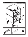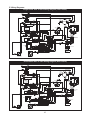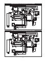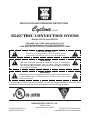
1
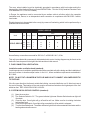
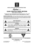
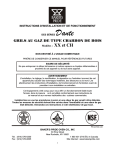
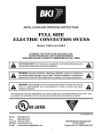
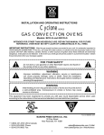
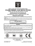
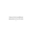
BAKERS
PRIDE
INSTALLATION AND OPERATING INSTRUCTIONS
Cyclone
SERIES
ELECTRIC CONVECTION OVENS
Models: BCO-E and GDCO-E
INTENDED FOR OTHER THAN HOUSEHOLD USE
RETAIN THIS MANUAL FOR FUTURE REFERENCE
OVEN MUST BE KEPT CLEAR OF COMBUSTIBLES AT ALL TIMES
FOR YOUR SAFETY
!
Do not store or use gasoline or other flammable vapors
and liquids in the vicinity of this or any other appliance.
WARNING
!
Improper installation, adjustment, alteration, service or maintenance
can cause property damage, injury or death. Read the Installation,
Operating and Maintenance Instructions thoroughly before installing or
servicing this equipment.
!
Initial heating of oven may generate smoke or fumes and must be done in
a well-ventilated area. Overexposure to smoke or fumes may cause
nausea or dizziness.
!
!
WARNING
!
This equipment has been engineered to provide you with year round dependable service when used
according to the instructions in this manual and standard commercial kitchen practices.
6/03 Form # 8898400 REV A
BAKERS PRIDE OVEN CO., INC.
30 Pine Street
New Rochelle, NY 10801
(914) 576-0200 Phone
(914) 576-0605 Fax
(800) 431-2745 US & Canada
www.bakerspride.com Web Address
1
INDEX
I. INSTALLATION INSTRUCTIONS
SECTION
ITEM
PAGE
A
Receiving
3
B
Set-up/Mounting
3
C
Installation with Casters
4
D
Location & Minimum Clearances
4
E
Electrical Connections
4
F
Flue Connection Ventilation
5
G
System Check - Rotary Controls
5
II. OPERATING INSTRUCTIONS
SECTION
ITEM
PAGE
A
General Instructions
6
B
Operation Sequence For Rotary Controls
1. Cook Only
2. Timed Cooking
3. Cook & Hold
4. Steam Injection (Optional)
5. Oven Cool Down
6
6
6
7
7
7
C
Cleaning
7
D
Servicing
8
E
Wiring Diagrams
1. Single Phase 208V or 240V Wiring Diagram
(Dial Control)
2. Three Phase 208V or 240V Wiring Diagram
(Dial Control)
3. Single Phase 208V or 240V Wiring Diagram
(CH-100 Control)
4. Three Phase 208V or 240V Wiring Diagram
(CH-100 Control)
10
10
F
International Distribution and Service Centers
2
10
11
11
12
I. INSTALLATION INSTRUCTIONS
A. RECEIVING
Read the notice on the outside carton regarding damage in transit. Damage discovered after opening
the carton is “CONCEALED DAMAGE.” Carrier must be notified immediately to send an inspector and
to furnish forms for claims against the carrier.
When the oven arrives, it should consist of:
A crate or carton containing your new oven (two for a stacked unit).
A carton containing four 31” legs with mounting hardware (set of four 6” legs is supplied for stacked
installations).
A carton containing a Flue Adapter and a Draft Hood. Optional: for Direct Venting (Not available for
European Community Countries).
B. SET UP / MOUNTING:
NOTE:
This appliance must be installed by competent personnel in accordance with the rules in force.
Your oven will be packed sitting on its bottom. The skid may be left under the oven for convenience in
further handling. Unpack carefully, avoiding damage to the Stainless Steel front and/or trim. If
concealed damage is found, follow the instructions detailed in Section A (Receiving). Keep the area
around the ovens free and clear of combustible materials. Do not store any materials on top of or under
any oven. The provision of adequate air supply to your oven for ventilation is essential. As a minimum,
observe the clearances detailed in Section D (Location). Provide adequate ventilation and make up air
in accordance with local codes. Servicing your oven is done through the front control panel and right
side access cover. Ensure that these areas are kept unobstructed for easy access.
For a single unit:
(1) Tilt Oven over to left-hand side and attach two 31” legs on the right-hand side with four 3/8-16”
bolts and washers. Tighten firmly.
(2) Using proper lifting equipment, lift up the left-hand side and attach two 31” legs on the left-hand
side the same way.
For a stack of two ovens: Refer to Figure 3
(1) Remove flue from top oven and replace with flue-adaptor supplied in the stacking kit.
(2) Tilt lower unit over to the left side and position two 6" legs on the right side (one for front and one
for back), secure in place by using 4 bolts (3/8-16) per leg. Tighten firmly.
(3) Using proper lifting equipment, lift up the left side of the unit and attach the other two legs in the
same way.
(4) Using the lifting equipment, raise the top oven to proper height and slide onto top of the bottom
oven. Line up sides and front and fasten to each other at the rear of the units by using a
mounting bracket supplied in the stacking kit.
To assemble an open rack stand: Refer to Figure 2
(1) Loosen 12 bolts (attaching 31” legs) slightly.
(2) Remove 4 inner bolts, 1 from each of the 4 legs, place top right angle and top left angle
underneath and tighten these 4 bolts.
(3) Insert “Open Rack Shelf” and tighten into place with eight 3/8-16 screws, washers and nuts.
(4) Position “Rack Supports” and tighten in place using 4 each of flat washers and 5/16-18 Hex
Nuts.
3
C. INSTALLATION WITH CASTERS (OPTIONAL):
Four casters (two with wheel brakes) and the mounting hardware are packed and included in the
shipment if ordered. Install casters with wheel brakes on the front of the unit. Installation must conform
to UL 197: Electrical Supply Connections For Permanently Connected Appliances. It requires that
permanently connected appliances with casters be provided with a means for securing the appliance to
the building structure to limit the movement of the appliance.
Oven Restraint: When casters are installed on either a single or double unit, a fixed restraint must be
used to limit the movement of the appliance without depending on or transmitting stress to the electrical
conduit. The restraint (a heavy-gauge cable) should be attached to the rear legs of the oven on which
casters are mounted. If disconnection of the restraint is necessary, the restraint must be reconnected
after the oven has been repositioned in its permanent location. The appliance shall be installed using
flexible conduit.
D. LOCATION AND MINIMUM CLEARANCES:
Move the oven to its final location keeping the minimum clearance from the back of the oven to the wall.
This clearance is necessary for safe operation and to provide proper air flow.
MINIMUM CLEARANCES FROM COMBUSTIBLE AND NONCOMBUSTIBLE CONSTRUCTION
Under Ventilation Hood
RIGHT WALL
1”
LEFT WALL
1”
REAR WALL
3”
!
SUITABLE FOR INSTALLATION ON COMBUSTIBLE FLOOR WHEN
INSTALLED WITH LEGS OR CASTERS PROVIDED.
!
!
CAUTION: DO NOT SET THE OVEN WITH ITS BACK FLAT AGAINST THE
WALL. IT WILL NOT OPERATE PROPERLY UNLESS THERE IS AT LEAST
THREE INCHES BREATHING SPACE BEHIND THE OVEN
!
!
NOTICE: LOCAL CODES REGARDING INSTALLATION VARY GREATLY
FROM ONE AREA TO ANOTHER. THE NATIONAL FIRE PROTECTION
ASSOCIATION, INC., STATES IN IT’S NFPA 96 LATEST EDITION THAT LOCAL
CODES ARE “AUTHORITY HAVING JURISDICTION” WHEN IT COMES TO
REQUIREMENTS FOR INSTALLATION OF EQUIPMENT. THEREFORE,
INSTALLATIONS SHOULD COMPLY WITH ALL LOCAL CODES.
!
E. ELECTRICAL CONNECTION:
Install according to the spacing requirements listed in the installation section of this manual. We strongly
recommend having a competent professional install this equipment. A licensed electrician should make
the electrical connections and connect power to the unit. Local codes should always be used when
connecting these units to electrical power. In the absence of local codes, use the latest version of the
National Electrical Code.
Note: For supply connections use No. 6 AWG wires suitable for at least 90°C.
4
The oven, when installed, must be electrically grounded in accordance with local codes and/or the
latest edition of the National Electrical Code ANSI/NFPA No. 70 in the USA (Canadian Electrical Code
CSA Standard C22.1, Part 1 in Canada).
In Europe, the appliance must be connected by an earthen cable to all other units in the complete
installation and, thence, to an independent earth connection in compliance with EN 60335-1 and/or
local codes.
Electrical power is to be supplied to the oven(s) by means of hard wiring, which is to be performed by a
qualified licensed electrician.
BCO-E, GDCO-E
Motor-50hz
Amps
Model
KW Voltage
10.5
BCO-E, GDCO-E
208
Phase
1
Line 2
Line 3
N
48
48
-
-
-
-
850
1725
-
-
850
1725
850
1725
-
-
850
1725
3
30
30
10.5 220-240
1
44
44
28
-
10.5 220-240
3
26
26
24
-
208
RPM RPM RPM RPM
(Low) (High) (Low) (High)
Line 1
-
10.5
Motor-60hz
Each oven requires separate electrical connectionsl
Normal factory connections are made for 208 V.A.C. or 208/240 V.A.C., 60 hz.
This unit is provided with a permanently lubricated electric motor. A wiring diagram may be found on the
back of the service panel on the right-hand side and also in this manual.
F. FLUE CONNECTION VENTILATION:
Installation under ventilation hood (standard):
Local inspectors and ventilation specialists should be consulted so that the design and the installation of
the hood conform to local/municipal codes. In the U.K., follow ventilation requirements as detailed in
B.S. 5440.
NOTE: DO NOT PUT A DAMPER IN THE FLUE AND DO NOT CONNECT A BLOWER DIRECTLY
TO THE FLUE.
If the flue runs directly to the free air outside the building, use a wind deflector or a UL listed vent cap at
the end of the pipe. Termination of the vent must be at least two feet above the highest part of the roof
within ten feet. REF: AGA CATALOG NO. XH0474.
G. SYSTEM CHECK- ROTARY CONTROL (standard):
(1) Open the oven door.
(2) Turn Selector Switch to “HI.” The green indicator light near Selector Switch and oven light will
illuminate.
(3) Close the door. Oven lights will go off and fan will run. Make sure fan is rotating clockwise
looking from front.
(4) Press Oven Light switch. Oven light will go on and will go off as switch is released.
(5) Turn the thermostat knob. The amber indicator light near the thermostat will illuminate and the
heating elements will come on.
5
(6) Turn the timer knob past 10 minutes and back to 2 minutes. At the end of 2 minutes the buzzer
will sound. Reset by turning to “0.” All settings below 10 minutes require turning past 10
minutes and then back to the time required.
(7) Open the oven doors. Oven lights will go on and elements and fan will go off.
(8) Turn Selector Switch to “Cool Down” position. The fan will run to cool down the oven.
(9) Turn Selector Switch to “0” position.
(10) Close the oven doors.
NOTE: WITH THE DOORS CLOSED, THE POWER SWITCH “ON” AND THE SELECTOR SWITCH
IS IN ANY POSITION OTHER THAN “0”, THE OVEN WILL START HEATING AS SOON AS THE SET
TEMPERATURE IS HIGHER THAN THE OVEN TEMPERATURE.
THERMOSTAT INDICATOR LIGHT GOES OUT WHEN OVEN REACHES SET TEMPERATURE
AND COMES ON WHEN OVEN IS HEATING UP.
IN THE EVENT OF POWER FAILURE, THE OVEN WILL NOT OPERATE.
PROGRAMMING MENUS:
!
See Operating/Programming Instruction Booklet for Programmable
Oven Control with Bakers Pride Software for Cyclone
Series Convection Ovens supplied with this option.
!
II. OPERATING INSTRUCTIONS
A. GENERAL INSTRUCTIONS:
(1) This equipment has an Electronic Temperature Control.
(2) Due to increased efficiency of this oven, the temperature of standard recipes may be reduced
50°F (30°C).
(3) Always load each shelf evenly. Space pans away from each other and from sides and back of
oven to allow maximum air flow between them.
(4) Large tempered glass windows and interior lights allow a close check on the product making it
unnecessary to frequently open the doors. Products cook faster in a convection oven as
compared to a conventional oven. Depending on the product and the type of pans used, time
saving may run from 20 percent to as high as 50 percent.
B. OPERATION SEQUENCE ROTARY CONTROL:
Cook only rotary control:
(1) Close the oven doors.
(2) Turn Selector Switch to “HI” or “LO” position. The indicator light near the Selector Switch will be
illuminated.
(3) Turn the thermostat knob to the desired cooking temperature.
(4) Upon reaching the set temperature, the indicator light near the thermostat will go out.
(5) Load the oven with product to be cooked.
(6) Remove the product from the oven when done.
Timed cooking rotary control:
(1) Close the oven doors.
(2) Turn Selector Switch to “HI” or “LO” position. The indicator light near the Selector Switch will be
illuminated.
(3) Turn the thermostat knob to the desired cooking temperature.
(4) Upon reaching the set temperature, the indicator light near the thermostat will go out.
(5) Load the oven with product to be cooked.
(6) Turn the timer knob to the desired bake time and timer will start counting down.
6
(7) When timer reaches zero, a buzzer will sound.
(8) Turn the timer knob to “O” position.
(9) Remove the product from the oven.
NOTE: TIMER DOES NOT CONTROL THE OVEN.
Cook and Hold Rotary Control:
(1) Close the oven doors.
(2) Turn Selector Switch to “HI” or “LO” position. The indicator light near the Selector Switch will be
illuminated.
(3) Turn the thermostat knob to the desired cooking temperature.
(4) Upon reaching the set temperature, the indicator light near the thermostat will go out.
(5) Load the oven with product to be cooked.
(6) Turn the timer knob to the desired bake time and timer will start counting down.
(7) When timer reaches zero, a buzzer will sound.
(8) Turn the Timer knob to “O” position.
(9) Turn the thermostat knob to the desired hold temperature.
(10) Remove the product from the oven when done.
Optional steam injection Rotary control:
The solenoid valve for steam injection is mounted behind the service panel on the right-hand side of the
unit. The electronic timer is preset at the factory. A ¼” copper tubing is provided on the Solenoid Valve
for water hookup with a compression fitting. After the water hookup is made, make sure that there are no
leaks. For steam injection, press the Steam switch momentarily.
NOTE: DO NOT USE STEAM INJECTION AT TEMPERATURES BELOW 275°F (135°C).
Oven cool down Rotary control:
To cool down the oven to a lower desired temperature, follow the steps detailed below.
(1) Open the oven doors.
(2) Turn Selector Switch to “oven cool down” position. Fan will now operate and cool down the
oven.
(3) When the oven has cooled down to the desired temperature, turn the Selector Switch to “O”
position. Close oven doors.
C. CLEANING:
!
CLEAN ONLY WHEN OVEN IS COLD
SHOCK HAZARD
De-energize all power to
equipment
before cleaning the
equipment.
!
!
WARNING
Never clean any electrical
unit by immersing it in water.
Turn unit off before cleaning
surface.
!
(1) With porcelain enamel interiors, this oven is designed to be as maintenance free as
possible. However, for best results, the oven should be cleaned regularly. Enameled
interiors can be easily cleaned with oven cleaners. KEEP CLEANING FLUIDS AWAY
FROM ELECTRICAL WIRES, LIGHT SOCKETS, SWITCHES AND CONTROL PANEL.
(2) Baked on splatter, oil, grease or discoloration on the stainless steel front or inside of the oven
may be removed with stainless steel cleaner, or any other similar cleaning agent.
NOTE: ALWAYS RUB THE STAINLESS STEEL ALONG THE GRAINS.
(3) To clean the blower wheel, remove and immerse in ammoniated water for 20 to 25 minutes.
Then, scrub it off with a small, stiff brush. The same procedure can be followed for wire racks
and rack supports. To remove the blower wheel, loosen the set screws (2) on the hub of the
blower wheel and tighten the 3/8” wheel puller bolt (supplied) in center of hub (See Fig. 1).
(4) To clean wire shelves and rack supports, remove and immerse in ammoniated water for 20 25 minutes. Use a small stiff brush to remove any remaining dirt/debris (See Figure 2).
7
Cleaning The Blower Wheel
Figure 1
Blower Wheel
Set Screws (2)
Motor
Wheel Puller Bolt 3/8”-Hex
D. SERVICING:
NOTE: THIS APPLIANCE MUST BE SERVICED BY AN AUTHORIZED SERVICE AGENT.
(1) Power supply to the unit must be disconnected before any service is performed.
(2) Most of the service on the unit can be performed from the front and/or control panel side.
(3) For proper servicing, access to the control panel side of the unit will be required.
(4) It will be necessary to have access to the back of the oven for service needs related to the
electric power supply.
(5) A system wiring diagram is provided in this manual and on the back of the service panel on the
right side of the oven.
(6) All servicing should be performed by a factory-authorized technician only.
(7) For proper maintenance and repairs, call the factory toll free (800-431-2745) for an authorized
service agency in your area.
!
CAUTION
This product, when stacked, has
more than one power-supply
connection point. Disconnect all
power supplies before servicing.
WARNING-RISK OF FIRE
!
!
When stacked two high
maximum, use stacking kit
part # E3771A only.
!
Open Rack Stand
Figure 2
Top Left Angle
31” Legs
Top Right Angle
1/2” Flat Washer
(4 corners only)
3/8”-16 x 3/4” large
Truss Head Screw
w/Nut & Washer (8)
1/2”-13 x 1” Large
Hex Head Bolt (12)
5/16” Flat Washer (4)
Open Rack Shelf
Rack Support
5/16”-18 Hex Nut (4)
8
Figure 3
Stacking Two Ovens
REMOVE FLUE FROM TOP OVEN
AND REPLACE WITH ITEM 1
1
2
3
Item 1
Item 2
E3770A
E3771A
9
Item 3
3/8”-16 Bolt
E. Wiring Diagrams:
Single Phase 208V or 240V Wiring Diagram (Dial Control)
Green Power Light
18
2
1
27
Centrifugal Switch
High
10
23
30
4
2 Speed
1725/850
48
1
Low
MOTOR
2
Amber Pilot Light
Centrifugal Switch
24
T1TOT4
T4 T5 T2
T1TOT2
Com
3
RTD Probe
T1 T3
T3 TOT2
47
Probe
Thermostat
T’stat Relay
Lights
26
25
8
4
Front
Element
32
6
9
T6 T7 T8 T9T10T11
46
7
37
33
36
34
23
Light Push
Button Switch
28
35
9
Buzzer
Timer
A1
5
49
4
22
1
4 Pole, 40 Amp
Contactor
A2
11
L1
21
L1
38
L2
29
39
Fuse Box
13
44
L2
L3
41
12
L4
42
45
16
Power
17
Ground Stud
14
15
6
L1 L3 L 2
3
43
NC
Single Phase
208/240V
44
C
29
NO
Doors Close To
Activate Switch
Cooling Fan
Three Phase 208V or 240V Wiring Diagram (Dial Control)
Green Power Light
18
2
1
27
Centrifugal Switch
2 Speed
1725/850
48
10
23
30
High
4
Low
1
MOTOR
2
Centrifugal Switch
Amber Pilot Light
24
T1TOT4
T4 T5 T2
T1TOT2
COM
RTD Probe
3
T1 T3
T3 TOT2
47
Probe
Thermostat
T’stat Relay
Front
Element
Lights
6
9
T6 T7 T8 T9T10T11
32
26
25
8
4
46
7
37
33
36
34
23
Light Push
Button Switch
9
28
Buzzer
Timer
4
A1
5
49
22
1
L2
L1 2
L
38
39
Fuse Box
13
44
4 Pole, 40 Amp
Contactor
A2
11
L1
21
29
12
41
L3
L4
42
45
16
Power
17
Ground Stud
14
15
6
3
43
NC
29
44
C
NO
Doors Close To
Activate Switch
35
Cooling Fan
10
L1 L3 L2
Three Phase
208/240V
Single Phase 208V or 240V Wiring Diagram (CH-100 Control)
18
2
1
27
CENTRIFUGAL SWITCH
HIGH
FAN
MOTOR MOTOR
6
FUSE BOX
4
48
CENTRIFUGAL SWITCH
RELAY
8
T1TOT2
7
46
6
19
27
T1TOT4
3
18
10
29
COM
T3TOT2
24
DOOR
47
45
44
PROBE
HEAT
FRONT
ELEMENT
9
32
4
33
GND
LOW
2
23
22
28
1
37
36
35
34
21
FAN
20
A1
5
26
25
4 POLES, 40 AMPS
CONTACTOR
A2
11
38
10
LIGHTS
39
41
9
12
42
13
Ground
Stud
16
POWER
L1 L3 L2
SINGLE PHASE
17
208/ 240V
14
NC
15
C
NO
DOORS ACTIVATE
SWITCH WHEN
CLOSED
30
31
Three Phase 208V or 240V Wiring Diagram (CH-100 Control)
18
2
1
27
CENTRIFUGAL SWITCH
6
FUSEOX
B
RELAY
45
44
PROBE
2
8
46
6
19
27
COM
T1TOT4
T1TOT2
3
18
10
29
CENTRIFUGAL SWITCH
T3TOT2
24
DOOR
47
7
9
FRONT
ELEMENT
32
4
33
GND
LOW
1
48
23
HEAT
4
MOTOR
22
28
HIGH
FAN
MOTOR
37
36
35
34
21
FAN
20
5
26
25
A1
4 POLES, 40 AMPS
CONTACTOR
A2
11
38
10
LIGHTS
39
9
12
41
42
13
Ground
Stud
16
POWER
L1 L 3 L 2
THREE PHASE
17
NC
C
208/240V
14
15
NO
DOORS ACTIVATE
SWITCH WHEN
CLOSED
30
31
COOLING
FAN
11
F. INTERNATIONAL DISTRIBUTION AND SERVICE CENTERS
BAKERS
PRIDE
BAKERS PRIDE
INTERNATIONAL
30 Pine Street
New Rochelle, NY 10801 USA
+1 (914) 576-0200
+1 (914) 576-0605 fax
[email protected]
www.bakerspride.com
RUSSIA
Perfi, Ltd. — Dmitri Slavin
22 Marksistskaya Street
Moscow, Russia 109147
+7 (095) 912 4100
+7 (095) 913 3553 fax
[email protected]
729 Third Avenue
Dallas, TX 75226 USA
+1 (214) 421-7366
+1 (214) 565-0976 fax
[email protected]
NETHERLANDS
CANADA
Wisselaar Fast Food & Systeemgastronomie B.V.
— Jankees Rovers
Nijverheidsweg 41
3341 LJ, Hendrik Ido Ambacht
The Netherlands
+31 (78) 683 3833
+31 (78) 683-3830 fax
www.wisselaar.nl
Rabco — Steve Vella
4500 Sheppard Avenue E.
Unit 9-11 Scarborough
Ontario Canada MIS 3R6
+1 (416) 321-5823
+1 (416) 321-5826 fax
[email protected]
GERMANY
UNITED KINGDOM / IRELAND
FEM Food Equipment Mktg — Horst Herbert
Fuchshaldeweg 37
D-77654 Offenburg, Germany
+49 (781) 32077
+49 (781) 42365 fax
[email protected]
www.femgmbh.com
BAKERS PRIDE Europe — Tim White
Wealden Est Farningham Rd
Crowborough, E. Sussex, TN6 2JR
United Kingdom
+44 (1892) 667 311
+44 (1892) 667 322 fax
[email protected]
ASIA / AFRICA/ ME / C ARIBBEAN
/ MEXICO / LATIN AMERICA
GREECE
Heinami S. A. — Thanos Georgacopoulos
87 Alimou Avenue
17455 Alimos, Greece
+30 (210) 99 66 040
+30 (210) 99 66 047 fax
[email protected]
www.heinami.gr
Dorian Drake International
2 Gannett Drive
White Plains, NY 10604 USA
+1 (914) 697-9800
+1 (914) 697-9190 fax
[email protected]
www.doriandrake.com
JAPAN
DENMARK
Niwa Shoji Kaisha - Proserv — Akio Matsunaga
3-4-26, Tsukamoto
Yodogawa-ku, Osaka, 532-0026
Japan
+81 (6) 6307 7471
+81 (6) 6307 9181 fax
[email protected]
FiBeMa Catering Udstyr Aps.
Kodboderne 18, Kodbyen
1714 Copenhagen, Denmark
+45 (33) 21 33 70
+45 (31) 21 10 30 fax
[email protected]
www.fibema.dk
FRANCE
SCAL — Jacques Merran
20 Ave de la Baltique
Za Courtaboeuf 1
Courtaboeuf Cedex 91958
France
+33 (1) 6982 8585
+33 (1) 6982 8599 fax
www.scal.fr
NORWAY
Einar Riise & Son — Svein Riise
Enebakkveien 64C
Oslo 6, Norway
+47 (2) 208 3300
+47 (2) 219 0317 fax
[email protected]
www.riise.no
BAKERS PRIDE OVEN CO., INC.
30 Pine Street
New Rochelle, NY 10801
(914) 576-0200 Phone
(914) 576-0605 Fax
12
(800) 431-2745 US & Canada
www.bakerspride.com Web Address