1
Aruba AP 60/61
Access Point
Installation Guide
Copyright
© 2005 Aruba Wireless Networks, Inc. All rights reserved.
Trademarks
Aruba Networks and Aruba The Mobile Edge Company are trademarks of Aruba
Wireless Networks, Inc.
Specifications are subject to change without notice.
Sygate On-Demand Agent and Sygate Enforcer are trademarks of Sygate
Technologies.
All other trademarks or registered trademarks are the property of their respective
holders.
Legal Notice
The use of Aruba Wireless Networks, Inc. switching platforms and software, by
all individuals or corporations, to terminate Cisco or Nortel VPN client devices
constitutes complete acceptance of liability by that individual or corporation for
this action and indemnifies, in full, Aruba Wireless Networks, Inc. from any and all
legal actions that might be taken against it with respect to infringement of
copyright on behalf of Cisco Systems or Nortel Networks.
ii
Aruba AP 60/61
Installation Guide
0500160
December 2005
Contents
Chapter 1
Introduction . . . . . . . . . . . . . . . . . . . . . . . . . . . . . . . . . . . . . . . . . . . . . .
Front View . . . . . . . . . . . . . . . . . . . . . . . . . . . . . . . . . . . . . . . . . . . . . . . . . .
Back View . . . . . . . . . . . . . . . . . . . . . . . . . . . . . . . . . . . . . . . . . . . . . . . . . .
The Aruba AP Setup Process . . . . . . . . . . . . . . . . . . . . . . . . . . . . . . . .
1
2
5
6
Chapter 2
Provisioning Access Points . . . . . . . . . . . . . . . . . . . . . . . . . . . . 7
Aruba Discovery Protocol . . . . . . . . . . . . . . . . . . . . . . . . . . . . . . . . . . . . 8
AP Reprovisioning . . . . . . . . . . . . . . . . . . . . . . . . . . . . . . . . . . . . . . . . 9
AP Provisioning . . . . . . . . . . . . . . . . . . . . . . . . . . . . . . . . . . . . . . . . . . . . . 9
Manual Provisioning . . . . . . . . . . . . . . . . . . . . . . . . . . . . . . . . . . . . . . . . 12
Requirements . . . . . . . . . . . . . . . . . . . . . . . . . . . . . . . . . . . . . . . . . . . . 12
Connecting the Console Terminal . . . . . . . . . . . . . . . . . . . . . . . . . . . 14
Console Access to the AP . . . . . . . . . . . . . . . . . . . . . . . . . . . . . . . . 14
Setting Aruba AP 60/61 Parameters . . . . . . . . . . . . . . . . . . . . . . . . . 17
Chapter 3
AP Deployment. . . . . . . . . . . . . . . . . . . . . . . . . . . . . . . . . . . . . . . . .
Mounting the Aruba AP 60/61 . . . . . . . . . . . . . . . . . . . . . . . . . . . . . .
Aruba 60 Detachable Antennas . . . . . . . . . . . . . . . . . . . . . . . . . . .
Free-Standing Placement . . . . . . . . . . . . . . . . . . . . . . . . . . . . . . . . .
Using the Built-In Mounting Slots . . . . . . . . . . . . . . . . . . . . . . . . .
Using the Optional Mounting Kits . . . . . . . . . . . . . . . . . . . . . . . . .
Connecting Required Cables . . . . . . . . . . . . . . . . . . . . . . . . . . . . . . . .
Selecting an FE Cable . . . . . . . . . . . . . . . . . . . . . . . . . . . . . . . . . . . .
Connecting Cables & Power . . . . . . . . . . . . . . . . . . . . . . . . . . . . . .
Selecting an Antenna . . . . . . . . . . . . . . . . . . . . . . . . . . . . . . . . . . . . . . .
Maintenance . . . . . . . . . . . . . . . . . . . . . . . . . . . . . . . . . . . . . . . . . . . . . . .
21
Troubleshooting . . . . . . . . . . . . . . . . . . . . . . . . . . . . . . . . . . . . . . . .
Accessing the AP Support Prompt . . . . . . . . . . . . . . . . . . . . . . . . . .
Direct SPOE Connection to Mobility Controller . . . . . . . . . . . .
Direct Terminal Connection . . . . . . . . . . . . . . . . . . . . . . . . . . . . . . .
Remote Telnet Connection . . . . . . . . . . . . . . . . . . . . . . . . . . . . . . .
AP Support . . . . . . . . . . . . . . . . . . . . . . . . . . . . . . . . . . . . . . . . . . . . . . . .
Access Levels . . . . . . . . . . . . . . . . . . . . . . . . . . . . . . . . . . . . . . . . . . .
User Commands . . . . . . . . . . . . . . . . . . . . . . . . . . . . . . . . . . . . . . . . .
Privileged Commands . . . . . . . . . . . . . . . . . . . . . . . . . . . . . . . . . . . .
Resetting the AP to Factory Defaults . . . . . . . . . . . . . . . . . . . . . . . .
31
Appendix A
Aruba AP 60/61
Installation Guide
21
22
25
26
27
28
28
29
30
30
31
31
32
33
34
34
34
34
35
iii
Contents
Appendix B
Appendix C
Port Specifications. . . . . . . . . . . . . . . . . . . . . . . . . . . . . . . . . . . . .
FE Port . . . . . . . . . . . . . . . . . . . . . . . . . . . . . . . . . . . . . . . . . . . . . . . . . . . .
Serial Breakout Adapter . . . . . . . . . . . . . . . . . . . . . . . . . . . . . . . . . . . . .
DB-9 Specification . . . . . . . . . . . . . . . . . . . . . . . . . . . . . . . . . . . . . . .
“To AP” Specifications . . . . . . . . . . . . . . . . . . . . . . . . . . . . . . . . . . .
“To Network” Specifications . . . . . . . . . . . . . . . . . . . . . . . . . . . . . .
37
Product Specifications . . . . . . . . . . . . . . . . . . . . . . . . . . . . . . . .
Compliance . . . . . . . . . . . . . . . . . . . . . . . . . . . . . . . . . . . . . . . . . . . . . . . .
United States . . . . . . . . . . . . . . . . . . . . . . . . . . . . . . . . . . . . . . . . . . . .
Canada . . . . . . . . . . . . . . . . . . . . . . . . . . . . . . . . . . . . . . . . . . . . . . . . . .
Japan . . . . . . . . . . . . . . . . . . . . . . . . . . . . . . . . . . . . . . . . . . . . . . . . . . .
Europe . . . . . . . . . . . . . . . . . . . . . . . . . . . . . . . . . . . . . . . . . . . . . . . . . .
Certifications . . . . . . . . . . . . . . . . . . . . . . . . . . . . . . . . . . . . . . . . . . . . . . .
Product Label . . . . . . . . . . . . . . . . . . . . . . . . . . . . . . . . . . . . . . . . . . . .
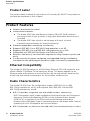
Product Features . . . . . . . . . . . . . . . . . . . . . . . . . . . . . . . . . . . . . . . . . . .
Ethernet Compatibility . . . . . . . . . . . . . . . . . . . . . . . . . . . . . . . . . . . .
Radio Characteristics . . . . . . . . . . . . . . . . . . . . . . . . . . . . . . . . . . . . .
Power Over Ethernet . . . . . . . . . . . . . . . . . . . . . . . . . . . . . . . . . . . . .
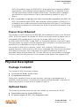
Physical Description . . . . . . . . . . . . . . . . . . . . . . . . . . . . . . . . . . . . . . . .
Package Contents . . . . . . . . . . . . . . . . . . . . . . . . . . . . . . . . . . . . . . .
Optional Items . . . . . . . . . . . . . . . . . . . . . . . . . . . . . . . . . . . . . . . . . . .
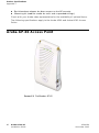
Aruba AP-60 Access Point . . . . . . . . . . . . . . . . . . . . . . . . . . . . . . . . . .
Aruba AP-61 Access Point . . . . . . . . . . . . . . . . . . . . . . . . . . . . . . . . . .
Related Documents . . . . . . . . . . . . . . . . . . . . . . . . . . . . . . . . . . . . . . . . .
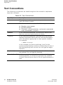
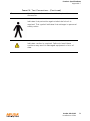
Text Conventions . . . . . . . . . . . . . . . . . . . . . . . . . . . . . . . . . . . . . . . . . .
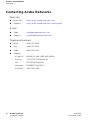
Contacting Aruba Networks . . . . . . . . . . . . . . . . . . . . . . . . . . . . . . . .
Proper Disposal of Aruba Equipment . . . . . . . . . . . . . . . . . . . . . . . .
41
37
38
38
39
39
41
41
42
43
43
45
46
46
46
46
47
47
47
47
48
53
57
58
60
61
Notes . . . . . . . . . . . . . . . . . . . . . . . . . . . . . . . . . . . . . . . . . . . . . . . . . . . . 63
iv
Aruba AP 60/61
Installation Guide
0500160
December 2005
1
Introduction
The Aruba AP 60/61 is part of a comprehensive wireless network solution. The
device works in conjunction with the Aruba Mobility Controller and can act as a
wireless access point or air monitor.
As a wireless Access Point (AP), the Aruba AP 60/61 provides transparent,
secure, high-speed data communications between wireless network devices
(fixed, portable, or mobile computers with IEEE 802.11a or IEEE 802.11b/g
wireless adapters) and the wired LAN.
As a wireless Air Monitor (AM), a feature unique to Aruba products, the Aruba AP
60/61 enhances wireless networks by collecting statistics, monitoring traffic,
detecting intrusions, enforcing security policies, balancing wireless traffic load,
self-healing coverage gaps, and more.
NOTE:
Installing the Aruba AP 60/61 requires setting the antenna power, which
requires professional training. The Aruba AP 60/61 installer must be
trained to perform this configuration.
Aruba AP 60/61
Installation Guide
1
Introduction
Chapter 1
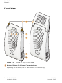
Front View
A
A
B
C
1
B
2
3
4
5
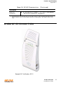
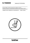
FIGURE 1-1
1
Aruba AP 60/61 Front View
Antenna fixtures for Wireless Communications
Depending on the model, the AP will have one of the following:
2
Aruba AP 60/61
Installation Guide
0500160
December 2005
Introduction
Chapter 1
A
Aruba AP60–Two Reverse Polarity SMA (RP-SMA) connectors for attaching
separate antennas (not included). For details, see “Aruba 60 Detachable
Antennas” on page 22. (The AP60 requires that both connectors be used in
ArubaOS 2.2 releases or lower. Single antenna operation is supported with
ArubaOS 2.3 or higher.)
NOTE:
B
2
When facing the A60 as shown in Figure 1-1, the antenna connector
on the left is for antenna 1, and the connector on the right is for
antenna 2 in a diversity configuration.
Aruba AP61–Built-in swivel array with dual, tri-band, omnidirectional
antennas
Indicator LEDs
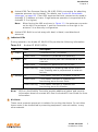
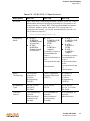
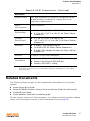
During operation, the Aruba AP 60/61 LEDs provide the following information:
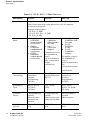
TABLE 1-1
LED
A
B
C
PWR
ENET
WLAN
NOTE:
3
Aruba AP 60/61 LEDs
State
Description
Off
The device is off - no power.
Green-Solid
The device is powered and operating.
Off
No link on the FE port. No connection to the
network.
Green-Solid
Ethernet link detected on the FE port.
Green-Flashing
Transmitting or receiving data across the FE
port. Flashing rate is proportional to network
activity.
Off
The wireless interface is disabled or down.
Green-Solid
The wireless interface is enabled and
functioning as an Access Point.
Green-Flashing
The wireless interface is enabled and
functioning as an Air Monitor.
LEDs on the Mobility Controller provide additional status and security
information about connected APs.See the ArubaOS User Guide for more
information.
Air Vents
These vents promote proper air circulation for cooling the device. Do not allow
these vents to be obstructed by mounting equipment, network cables, or any
other material.
Aruba AP 60/61
Installation Guide
3
Introduction
Chapter 1
4
FE Port
This port attaches the Aruba AP 60/61 to a 10Base-T/100Base-TX (twisted-pair)
Ethernet LAN segment. This port also supports Serial and Power Over Ethernet
(SPOE).
See Appendix C, “Product Specifications.” for port and cable specifications.
5
DC Power Socket
This socket is used to connect the optional AC power adapter (not included). If
POE is being used to supply power to the Aruba AP 60/61, the power adapter is
not necessary.
4
Aruba AP 60/61
Installation Guide
0500160
December 2005
Introduction
Chapter 1
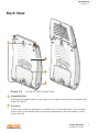
Back View
1
2
3
4
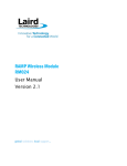
FIGURE 1-2
1
Aruba AP 60/61 Back View
Mounting Slots
The keyhole-shaped slots on the back of the chassis are used for mounting the
Aruba AP 60/61.
2
Air Vents
These vents promote proper air circulation for cooling the device. Do not allow
these vents to be obstructed by mounting equipment, network cables, or any
other material.
Aruba AP 60/61
Installation Guide
5
Introduction
Chapter 1
3
Fold-Out Stand
This fold-out stand allows the Aruba AP 60/61 to be stood upright on a table or
shelf.
4
Kensington Security Slot
This slot is compatible with a Kensington MicroSaver Security Cable (not
included) which can be used to prevent the unauthorized removal of the Aruba AP
60/61 from its installed location. To secure the Aruba AP 60/61, wrap a security
cable around an immovable object, insert the cable’s lock into the Kensington
Security Slot, and turn the key.
NOTE:
The serial number and model number are on the bottom of the unit.
The Aruba AP Setup Process
Setting up an Aruba AP typically consists of four stages:
WLAN Planning—The administrator determines how many Aruba APs will be
needed for their wireless network strategy and where they will be deployed. This
can be easily accomplished using Aruba’s automated RF Plan site-survey
software (available separately).
AP Provisioning—Provisioning provides each Aruba AP with initial settings that
allow it to locate the host Aruba Mobility Controller. Depending on the network
topology and services, AP provisioning can be performed manually for each AP or
plug-and-play for batches of APs.
AP provisioning is discussed in Appendix 2, “Provisioning Access Points.”
AP Deployment—Once provisioned, the AP can be physically installed at its
intended place of operation.
AP deployment is covered in Chapter 3, “AP Deployment”.
AP Configuration—The administrator defines the operational behavior for each
Aruba AP, such as RF characteristics and security features.
For AP configuration information, refer to the ArubaOS User Guide.
6
Aruba AP 60/61
Installation Guide
0500160
December 2005
Provisioning Access Points
2
Access Points are radio broadcast devices and as such are subject to
governmental regulation. Network administrators responsible for the
configuration and operation of Access Points must comply with local broadcast
regulations. Specifically, Access Points must use channel assignment and
antenna gain settings (for detachable antennas) appropriate to the location in
which the Access Point will be used. Aruba Networks, in compliance with
governmental requirements, has designed the AP60 and AP61 such that only
authorized network administrators can change these settings. For more
information on Access Point configuration, refer to the ArubaOS User Guide.
Provisioning provides the AP with initial network settings that allow it to locate
the host Aruba Mobility Controller. The following provisioning methods (listed in
the order of preference recommended by Aruba Networks) are available:
z
z
Plug and Play—Also known as the Aruba Discovery Protocol. This is the easiest method for AP provisioning. With plug and play, Aruba APs can be connected to the network and brought into operation automatically. Although
plug and play requires no manual intervention for the APs, this method does
require specific services to be configured on your network in advance.
AP Provisioning—Using this AP programming mode, AP configuration parameters are defined on the Mobility Controller (using the CLI or Web interface) and
then uploaded to the APs.
This method can be used for adding Aruba APs to a highly customized
network, or greatly simplified for the most common provisioning.
z
Manual Provisioning—APs can be individually provisioned using a serial console terminal connected to the AP. Although this method is complex and
requires considerable care, manual provisioning can be used in almost any
scenario, with or without access to the Mobility Controller.
NOTE:
Manual provisioning is intended for use when no Aruba Mobility
Controller is available, and is not generally recommended as the
primary method of AP provisioning. Plug and play or AP
programming mode are the preferred provisioning methods.
Aruba AP 60/61
Installation Guide
7
Provisioning Access Points
Chapter 2
Each of these three methods is explained in the following sections. Use these
procedures for initial provisioning of APs. To change the configuration for APs
that have already been provisioned, go to Maintenance > Program AP > Re-Provision.
See the ArubaOS User Guide for more information on reprovisioning existing APs.
CAUTION:
When an AP60 powers up for the first time, the Mobility
Controller will recognize that it is detachable-antennas
capable. The network administrator must set the antenna
gain manually before the AP60 can function as an Access
Point. Until the antenna gain is set, the AP60 with
detachable antennas will function as an Air Monitor but
will not process wireless packets as an Access Point.
Refer to the ArubaOS User Guide for instructions on
manually setting antenna gain.
Aruba Discovery Protocol
Aruba Discovery Protocol (ADP) is a plug and play provisioning tool for Aruba AP
60/61 Access Points. ADP performs two tasks:
z
z
Obtains the IP address of the TFTP server from which it downloads the AP
boot image
It discovers the IP address of the master Aruba Mobility Controller in the network from which the AP can download its configuration.
The address of the TFTP server that ADP discovers is the equivalent of the
BOOTROM environment variable serverip. The IP address of the Aruba master
Mobility Controller is the equivalent of the environment variable master.
ADP can discover these values using DHCP or by discovery. In the case of DHCP,
ADP relies on a DHCP server which is configured to return the IP address of the
Master Mobility Controller using the Vendor Specific Options in DHCP. To facilitate
ADP, Aruba APs include this Vendor Specific Option in the requested Option list,
and if the DHCP server is configured to return the IP address of the Master
Mobility Controller, the IP address will be a part of the DHCP response. This is
used by the AP to get its image as well as its configuration.
Discovery of the serverip and master variables is necessary when the DHCP response
does not include the Vendor Specific option. The AP attempts to discover an
Aruba Master Mobility Controller by sending multicast packets and broadcast
packets on its subnet. To use the ADP discovery method, the ADP discovery
mechanism needs to be enabled on the Aruba Master Mobility Controller (using
the adp discovery enable command).
If multicast routing is enabled in the IP network between the AP and the Master
Mobility Controller (which can be any one or more Aruba Mobility Controllers in
the network), the IGMP-Join option should be enabled on the Aruba Mobility
Controller (using the adp igmp-join enable command). If multicast routing is not
8
Aruba AP 60/61
Installation Guide
0500160
December 2005
Provisioning Access Points
Chapter 2
enabled on the network, the Aruba Mobility Controllers need to be on the same
broadcast domain as the AP or an “IP Helper” must be configured to direct the
broadcast ADP packets to the Aruba Mobility Controller.
Once these discovery prerequisites are met, the Mobility Controller will respond
to APs with the IP address of the Master Aruba switch. The APs can then obtain
their image and configuration.
To enable ADP on an Aruba Mobility Controller, enter:
(A5000) (config) #adp discovery enable
To enable IGMP-Join on an ADP multicast group on an Aruba Mobility Controller,
enter:
(A5000) (config) #adp igmp-join enable
NOTE:
If you have location-specific configurations for your Access Points, you
will need to apply this configuration information using AP Reprovisioning.
Refer to the ArubaOS User Guide for details on AP Reprovisioning and
see the feature description below.
AP Reprovisioning
AP Reprovisioning is the process by which APs are assigned, for example,
location codes. Location codes are important for recalibration and triangulation.
For details on AP Reprovisioning, see the ArubaOS User Guide.
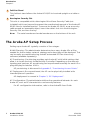
AP Provisioning
AP Provisioning is useful for brand new APs with default configurations. To
perform AP Provisioning from the WebUI:
1.
Go to Maintenance > Program AP.
On this window, there are two tabs: Provisioning and Reprovisioning. The
Provisioning tab is selected by default.
Aruba AP 60/61
Installation Guide
9
Provisioning Access Points
Chapter 2
FIGURE 2-1
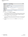
2.
Provisioning Tab
Configure the APs Subnet and Netmask.
This is the subnet from which the AP gets an IP during provisioning. (This is
not the IP address the AP will use when deployed. The provisioning subnet
should be not be the same as an existing subnet on Mobility Controller.)
3.
Select the Port or Port range for provisioning.
To set the Port Range, select the first and the last ports of your range. All the
ports in between are automatically selected. (Ports have to be sequentially
assigned.)
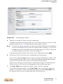
4.
10
Enter the required information and click Enable.The Port Range screen
displays.
Aruba AP 60/61
Installation Guide
0500160
December 2005
Provisioning Access Points
Chapter 2
FIGURE 2-2
5.
Port Range Screen
Specify the Aruba AP 60/61-specific parameters.
Configure the gain value appropriate for the location in which this AP will be
deployed. (See Table 3-1 for appropriate antenna gain values.)
NOTE:
If the AP being provisioned is a model with detachable antenna capability
(such as an Aruba AP-60), enter the antenna gain in dBi(e.g., 4.0). This is
mandatory for all detachable antenna models as the AP will not bring up
its radio interface or function as an AP without it.
Complete specifying Master Discovery and IP Settings and click Apply.
6.
Plug the AP into one of the ports configured for provisioning.
If your AP is already plugged into the port, unplug it and plug it in again. If AP
is connected through POE, enter (in interface mode) no poe followed by poe.
The AP will come up with an IP from the provisioning subnet
After the AP comes up it should be in the provisioning list. Provisioning list
shows the list of APs which are plugged into the provisioning ports.
7.
The Clear Table button appears after an entry in the list appears.
To erase all the table entries, click Clear Table. (You cannot clear selected
entries.) If a number of APs are provisioned and you click Clear Table, only
the entries which come up afterwards can be provisioned.
Aruba AP 60/61
Installation Guide
11
Provisioning Access Points
Chapter 2
If the entry does not show up in the AP list, check network connectivity. Go
to the AP console and verify if the AP has come up with the IP from the
provisioning subnet.
8.
After the entry shows up on the page, configure the location, Host IP/Name,
Master IP address.
If AP is going to be assigned a static IP, click Use the following IP Address
and enter the IP address, Netmask, Gateway IP.
If the AP is going to obtain an IP address using DHCP, click Use IP Address
Using DHCP.
9.
After configuring the required parameters, select the entry from the list (AP to
which the configuration has to be applied) and click Apply.
The State field changes from U (Unprovisioned) to In Progress. to P
(Provisioned).
NOTE:
Check that the configured parameters are reflected in the AP list entry.
NOTE:
Aruba Networks recommends that you provision each AP for a unique
location as suggested by site-survey planning. Label each AP with this
location information and place the AP in its proper location. Failure to
place APs in the location for which they were provisioned will reduce the
effectiveness of such RF features as triangulation.
10. Click Back to return to the previous page
We can see that the Subnet is still configured and Port/s are selected.
11. When finished provisioning APs, click Disable to disable AP Provisioning.
NOTE:
Disable AP Provisioning after all the required APs are provisioned. Ports
that are enabled for provisioning do not handle traffic. Therefore plugging
an already provisioned AP into a port still set to provisioning mode will
prevent that AP from functioning.
Now the AP is configured with the Parameters given
12. Reboot the AP so the AP will come up with the new configured parameters.
Use the Reprovisioning tab for APs which are already deployed but need to be
reconfigured. See the ArubaOS User Guide for information on reprovisioning.
Manual Provisioning
Requirements
z
12
A console terminal (or workstation with terminal emulation software) with an
available serial communications port using a DB-9 male connector.
Aruba AP 60/61
Installation Guide
0500160
December 2005
Provisioning Access Points
Chapter 2
z
z
An Aruba serial breakout adapter kit, Part Number CA-SPOE-ADAPT-3, (not
included). (See “Connecting the Console Terminal” on page 14.)
Access to the Aruba AP 60/61 FE port through one of the following:
z
Direct contact with the AP, or
z
If the AP is already deployed, you must have access to the end of the FE
cable that leads directly to the AP with no intervening hubs, routers, or
other networking equipment.
The cable must be an 8-conductor, Category 5 UTP, straight-through FE
cable with RJ-45 connectors.
z
A power source for the Aruba AP 60/61. Use one of the following:
z
An optional AC power adapter (not included) and an AC power outlet
rated at 100~240 V, 50~60 Hz, or
z
The Aruba AP 60/61 FE port connected to an Aruba 800, 2400, or 5000
Mobility Controller that supports IEEE 802.3af Power Over Ethernet (POE)
via a 4- or 8-conductor, Category 5 UTP, straight-through FE cable.1
NOTE:
Only IEEE 802.3af Power Over Ethernet is supported for manual
provisioning. “Inline” or “midspan” POE devices require Aruba serial
breakout adapter, Part Number CA-SPOE-ADAPT-4.
1. IEEE 802.3af-complaint devices like the AP60 and AP61 use the same wire pairs for data
versus for power. Within the 802.3af standard, there are two sub-specifications on how
wire pairs are assigned. Aruba conforms to 802.3af, subparagraph a. If your POE
installation uses all-Aruba equipment, you are assured proper operation. However, if you
use non-Aruba POE equipment, make sure it conforms to the same standard that Aruba
uses. Using POE equipment using IEEE 802.3af subparagraph b wiring assignments, or
POE equipment not conforming to the 803.2af standard may result in damaged
equipment.
Aruba AP 60/61
Installation Guide
13
Provisioning Access Points
Chapter 2
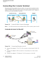
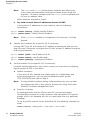
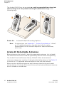
Connecting the Console Terminal
Manual provisioning requires this procedure. You must use the serial console
breakout adapter cable to be able to access the serial console interface to the
Aruba AP 60/61 while allowing the device to be powered by the AC adapter or
POE (from an Aruba Mobility Controller).
Console Connection
via direct access to AP
Console
Terminal
Aruba AP
Deployed
Location
Console Connection
via networking closet
Console
Terminal
Aruba AP
LAN
Serial
Breakout
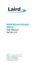
FIGURE 2-3
NOTE:
Serial
Breaout
Aruba AP 60/61 Console Topologies
The LAN connections are optional unless POE is used to power the AP.
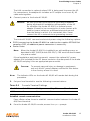
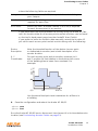
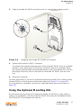
Console Access to the AP
2 DB-9 Connector
to Console Terminal
1 "To AP" Connector
to AP FE Port
"To Network" Connector
to FE Coupler
3 to LAN FE Cable
FIGURE 2-4
14
To LAN
Connecting Directly to the AP
1.
Connect the adapter’s “To AP” RJ-45 connector to the Aruba AP 60/61 FE
Port.
2.
Connect the adapter’s DB-9 connector to the serial port on the console
terminal.
3.
Connect the adapter’s “To Network” RJ-45 connector to the LAN.
Aruba AP 60/61
Installation Guide
0500160
December 2005
Provisioning Access Points
Chapter 2
The LAN connection is optional unless POE is being used to power the AP.
For convenience, the adapter kit includes an FE coupler to connect RJ-45
cable ends together.
4.
Connect power to the Aruba AP 60/61.
CAUTION:
Be sure to comply with electrical grounding standards
during all phases of installation and operation of the AP.
Do not allow the Aruba AP 60/61 or optional power
adapter (if used) to be connected to or make contact with
metal or power outlets on a different electrical ground
than the device to which it is connected. Also, never
connect the AP to external storm grounding sources.
The Aruba AP 60/61 can receive electrical power using the following options:
z
z
POE–If connecting the Aruba AP 60/61 to a device that supplies IEEE 802.3af
compliant POE, no additional power connection is necessary.
Power Outlet
NOTE:
When the Aruba AP 60/61 is installed in an air-handling space, as
described in NEC (2002) Article 300.22(C), POE must be used instead
of a power outlet.
If local regulations and practices permit, connect the optional AC power
adapter (not included) to the DC power socket on the rear panel of the Aruba
AP 60/61 and plug it into an appropriate power outlet.
CAUTION:
NOTE:
5.
To prevent personal injury or damage to equipment,
use only the AC power adapter certified for this device
in the country where it is used.
The indicator LEDs on the Aruba AP 60/61 will remain dark during this
procedure.
Set your local terminal to use the following communications:
TABLE 2-1
Console Terminal Settings
Baud Rate
Data Bits
Parity
Stop Bits
Flow Control
9600
8
None
1
None
Establish console communication.
Press <Enter> a few times to establish communication between the Aruba AP
60/61 and terminal.
6.
From the Aruba AP 60/61 console, access the apboot prompt.
Aruba AP 60/61
Installation Guide
15
Provisioning Access Points
Chapter 2
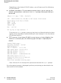
Depending on the Aruba AP 60/61 status, you will see one of the following
on your terminal:
z
Autoboot countdown—The countdown prompt allows you to interrupt the
normal startup process and access the apboot prompt where provisioning is
performed.
APBoot 1.2.1 (Apr
CPU:
Board:
DRAM:
POST:
FLASH:
Net:
7 2004 - 08:54:57)
AR2313 MIPS-32 at 180 MHz: 16 kB I-Cache 16 kB D-Cache
Merlot Local Bus at 90 MHz
32 MB
passed
4 MB
en0 lo0
Hit any key to stop autoboot:
0
To access the apboot prompt, press any key (such as <Enter>) before the timer
expires. If the countdown expires before you can interrupt it, turn the device
off and then back on.
z
TFTP time out—If the Aruba AP 60/61 cannot locate an Aruba Mobility Controller on its network port, the following type of output is repeatedly displayed:
Loading FLASH image...
Verifying checksum... failed!
BOOTP broadcast 1
DHCP IP address:
10.1.2.250
DHCP subnet mask: 255.255.255.0
DHCP def gateway: 10.1.2.1
DHCP DNS server:
10.1.1.2
DHCP DNS domain:
arubanetworks.com
DHCP Aruba server: 10.1.2.11
Loading elf file: 10.1.2.11:mips.ari
Loading: T T T T T T T T T
Retry count exceeded; starting again
Press <Control-C> to interrupt this process and access the apboot prompt.
Once the apboot prompt is displayed, perform provisioning as described in the
next section of this manual.
16
Aruba AP 60/61
Installation Guide
0500160
December 2005
Provisioning Access Points
Chapter 2
Setting Aruba AP 60/61 Parameters
1.
From the apboot prompt, configure the host information, if necessary.
In order to provide centralized management of the APs, each Aruba AP
downloads its software image and configuration files from a master Mobility
Controller.
Setting the correct host information depends on the following:
z
z
Does your network use direct IP addresses or DNS with host names?
If using host names, is aruba-master acceptable for the master Mobility Controller, or do you need to define a different name?
Depending on your answers, select one of the following steps:
z
My network uses DNS and the aruba-master host name is acceptable.
This is the default. It requires your DNS to be configured to resolve
“aruba-master” to the IP address of the master Mobility Controller. Unless
your system has been previously configured for different settings, you
can skip to Step 2.
Otherwise, if your system was previously configured for a different
setup, manually set the servername environment variable to the default
host name:
apboot> setenv servername aruba-master
NOTE:
The master and serverip environment variables also affect how AP
source files are selected and should be cleared when using this
approach. To clear a variable, enter the setenv variable command with
no host name or address value:
apboot> setenv master
apboot> setenv serverip
When finished, proceed to Step 2.
z
My network uses DNS, but I will use a different host name for the
Mobility Controller.
This requires that the servername variable be configured with your chosen
host name for the master Mobility Controller. It also requires that your
DNS be configured to resolve the specified host name to the IP address
of the master Mobility Controller.
To manually set the host name, use the following command:
apboot> setenv servername <Mobility Controller host name>
Aruba AP 60/61
Installation Guide
17
Provisioning Access Points
Chapter 2
NOTE:
The master and serverip environment variables also affect how
source files are selected and should be cleared when using this
approach. To clear a variable, enter the setenv variable command with
no host or address value.
When finished, proceed to Step 2.
z
My network uses direct IP addresses instead of DNS.
If using direct IP addresses in your network, use the following
commands:
apboot> setenv serverip <Mobility Controller IP address>
apboot> setenv master <Mobility Controller IP address>
NOTE:
2.
If the servername variable is configured in this scenario, it will be
ignored.
Specify an IP address for a specific AP, if necessary.
If using DHCP, the AP will obtain its IP address automatically and you can
skip this step. Otherwise, configure the AP with a static IP address using the
following commands:
apboot> setenv ipaddr <static IP address for the AP>
apboot> setenv netmask <static IP address mask>
apboot> setenv gatewayip <default gateway IP address>
3.
Set the location for the specific AP, if necessary.
Location settings depend on how much control you want over configuring
logical groups of APs in the future.
z
Default Locations
If you wish all APs treated as a single entity for configuration and
accounting purposes, you can use the default location profile
(255.255.65535) and skip to Step 4.
NOTE:
z
If using default locations during initial provisioning, you can later
reconfigure the APs to use specific location IDs using the Aruba
Mobility Controller management tools.
Specific Locations
By setting specific location IDs for each AP, you can later apply
configuration changes or collect statistics and information for specific
groups of APs (for example, all APs on a particular floor in a particular
building).
To set a specific location for an individual AP, the following command is
used:
setenv location <building number>.<floor number>.<device number>
18
Aruba AP 60/61
Installation Guide
0500160
December 2005
Provisioning Access Points
Chapter 2
where the following fields are required:
Building Number
A unique number (1-254) is required for each building in
your campus.
Floor Number
Within any building, a unique number (1-254) is
required for each floor.
Device Number
Within any floor, a unique number (1-65534) is required
for each access point or air monitor.
If you performed the recommended site survey using the Aruba RF Plan
tool, the location data for all access points and air monitors can be found
on the tool’s deployment page (see the ArubaOS User Guide).
If you prefer to enter the location data manually, record the location ID
you set for each access point and air monitor along with the following:
Note the intended function of the device (access point
or dedicated air monitor) and a brief description of its
service location.
X, Y
Coordinates
For each access point and air monitor, measure its X
and Y position (in feet) relative to the bottom-left corner
of the building plan as seen from overhead. For
example:
262 ft.
Device
Description
Y
98
0,0
126
X
418 ft.
Use the same fixed point and orientation for all floors in
a building.
4.
Save the configuration and reboot the Aruba AP 60/61.
apboot> save
apboot> boot
Once the Aruba AP 60/61 boots, disconnect it and mount it in its intended service
location (see Provisioning Access Points on page 21).
Aruba AP 60/61
Installation Guide
19
Provisioning Access Points
Chapter 2
20
Aruba AP 60/61
Installation Guide
0500160
December 2005
3
AP Deployment
This chapter covers the following topics:
z
z
Physical mounting of the Aruba AP 60/61
Connecting the required cables
Mounting the Aruba AP 60/61
When provisioning is complete, mount the Aruba AP 60/61 at its intended service
location.
The Aruba AP 60/61 Access Points with or without external antennas are
intended only for installation in Environment A as defined in IEEE 802.3.af. All
interconnected equipment must be contained within the same building, including
the interconnected equipment's associated LAN connections. (When using an
external antenna, 5.150 to 5.250 MHz are blocked.)
Select a location as close as possible to the center of the intended coverage area.
If necessary, use the Aruba RF Plan site survey tool to determine the optimum
locations for your access points and air monitors.
The service location should be free from obstructions or obvious sources of
interference. Normally, the higher you place an access point or air monitor, the
better its performance.
If external antennas are used, make sure that they and their associated wiring are
located entirely indoors. The Aruba AP 60/61 and any optional external antennas
are not suitable for outside use.
Aruba AP 60/61
Installation Guide
21
AP Deployment
Chapter 3
The Aruba AP 60/61 can be mounted on a wall or suspended from above (not
shown) using one of the optional mounting kits (dimensions vary) in the
following ways:
1
FIGURE 3-1
NOTE:
2
3
Aruba AP 60/61 Mounting Options
For dimensions, see Appendix C, “Product Specifications”. Allow 5
cm (2") additional space on the right-hand side for cables.
Measurements for the Aruba 60 depend on attached antennas,
which vary.
Aruba 60 Detachable Antennas
Before deploying the Aruba 60, attach the appropriate antennas (not included).
The antenna connections should be tightened by hand to avoid overtightening.
The Aruba 60 has dual Reverse Polarity SMA (RP-SMA) female antenna
connectors that accept a variety of high-gain detachable antennas. See Table 3-1
for the list of FCC approved antennas tested for use with the Aruba 60.
Make sure that all external antennas and their associated wiring are located
entirely indoors. The Aruba 60 Access Points and their optional external antennas
are not suitable for outside use.
22
Aruba AP 60/61
Installation Guide
0500160
December 2005
AP Deployment
Chapter 3
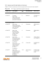
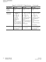
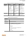
FCC-Approved Detachable Antennas
Table 3-1 lists the antennas which are approved for use with the Aruba 60.
TABLE 3-1
Aruba Part #
FCC-Approved Detachable Antennas
Description
Gain
dbi
Manufacturer
Man. Part #
5
Nearson
T614AH-2.4
5/5.X-S
MULTI-BAND ANTENNA
AP-ANT-1
Tri-Band,
High-Gain,
Omni-Directional
Antenna (Indoor)
(Swivel Connector)
2.4Ghz (802.11B/G)
AP-ANT-2
High-Gain,
Omni-Directional
Cylindrical (Indoor)
with RP-SMA
Connector
6
Centurion
IG2450-RPS
MA
AP-ANT-3
High-Gain,
Bi-Directional
Patch Antenna
(Indoor) with
RP-SMA
Connector
5
Centurion
IB2450-RPS
MA
AP-ANT-4
High-Gain,
Directional Patch
Antenna (Indoor)
with RP-SMA
Connector
9
Centurion
ID240-RPSM
A/CAF94379
AP-ANT-5
Down-Tilt,
Omni-Directional
Patch Antenna
(Indoor) with
RP-SMA
Connector
3.5
Cushcraft
SQ2403PG3
6RSM
AP-ANT-7
High-Gain
Directional Patch
Antenna (Indoor /
Outdoor) with
RP-SMA
Connector
11.5
HD Comms.
Corp
PCW24-080
12-AFL/HD1
9656
Aruba AP 60/61
Installation Guide
23
AP Deployment
Chapter 3
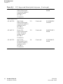
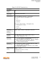
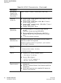
TABLE 3-1
FCC-Approved Detachable Antennas (Continued)
AP-ANT-8
High-Gain,
Omni-Directional
Cylindrical (Indoor /
Outdoor) with
RP-SMA
Connector
5
Cushcraft
S2403BPX3
6RSM
AP-ANT-10
High-Gain,
Omni-Directional
Cylindrical (Indoor /
Outdoor) with
RP-SMA
Connector
5.5
Cushcraft
S5153WBPX
36RSM
AP-ANT-11
Down-Tilt,
Omni-Directional
Patch Antenna
(Indoor) with
RP-SMA
Connector
3.5
Cushcraft
SQ5153WP3
6RSM
AP-ANT-12
High-Gain,
Directional Patch
Antenna (Indoor /
Outdoor) with
RP-SMA
Connector
14
Cushcraft
S52514WP3
6RSM
5Ghz (802.11A)
24
Aruba AP 60/61
Installation Guide
0500160
December 2005
AP Deployment
Chapter 3
Free-Standing Placement
To place the Aruba AP 60/61 indoors on a flat table or shelf:
Flip open the stand located on the back of the Aruba AP 60/61:
FIGURE 3-2
Aruba AP 60/61Fold-Out Stand
Place the device on a sturdy table or shelf.
CAUTION:
Do not place the Aruba AP 60/61 in any place where it
could fall on people or equipment. For more secure
installation, use one of the optional mounting kits.
Orient the antennas.
For best performance, swivel the individual antennas (Aruba 60) or antenna array
(Aruba AP61) so that they are oriented vertically. Once mounting is complete,
connect the required cables (see instructions on page 28).
Aruba AP 60/61
Installation Guide
25
AP Deployment
Chapter 3
Using the Built-In Mounting Slots
The keyhole-shaped slots on the back of the Aruba AP 60/61 can be used to
attach the device upright to an indoor wall or shelf.
CAUTION:
Do not use the mounting slots to hang the Aruba AP
60/61 from the ceiling, sideways, or in any place where it
could fall on people or equipment. For more secure
installation, use one of the optional mounting kits.
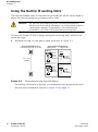
To hang the Aruba AP 60/61 upright using the mounting slots, perform the
following steps.
1.
Install two screws in the wall or shelf as shown in Figure 3-3:
Screw/Nail Positions
(fastened to wall or shelf)
Screw/Nail Dimensions
Maximum
Minimum
7.0 mm
12.7 cm
(5.00")
2.0 mm
3.8 mm
clearance
from surface
5.8 mm
1.3 mm
clearnace
from surface
3.0 mm
0.27"
0.08"
0.15"
clearance
from surface
0.23"
0.05"
clearance
from surface
0.12"
FIGURE 3-3
Mounting Screw Specifications
If attaching the device to drywall, we recommend using appropriate wall
anchors (not included) as shown in Figure 3-4 on page 27.
26
Aruba AP 60/61
Installation Guide
0500160
December 2005
AP Deployment
Chapter 3
2.
Align the Aruba AP 60/61 mounting slots to capture the surface screws.
FIGURE 3-4
3.
Hanging the Aruba AP 60/61 on Screws
Secure the Aruba AP 60/61, if desired.
To prevent the unauthorized removal of the Aruba AP 60/61 from its installed
location, use a Kensington MicroSaver Security Cable (not included). Wrap
the security cable around an immovable object, insert the cable’s lock into the
Kensington Security Slot on the back of the Aruba AP 60/61, and turn the
key.
4.
Orient the antennas.
For best performance, swivel the individual antennas (Aruba 60) or antenna array
(Aruba AP61) so that they are oriented vertically (see Figure 3-1 on page 22).
Once mounting is complete, connect the required cables (see instructions on
page 28).
Using the Optional Mounting Kits
Use the optional mounting kit to attach the Aruba AP 60/61 to a wall, shelf, or
ceiling. For installation, see the Aruba AP 60/61 Mounting Kit Installation Notes
(P/N 0500037-01) provided with each kit.
Aruba AP 60/61
Installation Guide
27
AP Deployment
Chapter 3
Connecting Required Cables
The Aruba AP 60/61 Access Points with or without external antennas are
intended only for installation in Environment A as defined in IEEE 802.3.af. All
interconnected equipment must be contained within the same building, including
the interconnected equipment's associated LAN connections.
Selecting an FE Cable
The 10/100 Mbps Ethernet (FE) port is used to connect the AP to a
10Base-T/100Base-TX (twisted-pair) Ethernet LAN segment. The appropriate FE
cable depends on the features required of the FE port:
z
SPOE
When connecting the AP to a device that supports Serial and Power Over
Ethernet (SPOE), use an 8-conductor, Category 5 UTP, straight-through FE
cable.
The Aruba 5000 (with Line Card LC-5000-24FE-2GE-SPOE), the Aruba 2400,
and the Aruba 800 support SPOE.
z
POE
If the connecting device supports only Power Over Ethernet (POE), use a 4- or
8-conductor, Category 5 UTP, straight-through FE cable.
z
Network Only
If the connecting device does not support POE, use a 4- or 8-conductor,
Category 5 UTP, FE cable. The port detects MDI/MDX and automatically
adjusts for straight-through or crossover cables.
The maximum length for FE cables is 100 meters (325 feet).
When the Aruba AP 60/61 is installed in an air-handling space, such as above
suspended ceilings, as described in National Electrical Code (2002) Article
300.22(C), and Canadian Electrical Code, Sections 2-128, 12-010(3) and 12-100,
Part 1, CSA C22.1, POE is required. Also, any FE cable installed in such spaces
should be suitable under NEC Article 800.50 and marked accordingly for use in
plenums and air-handling spaces with regard to smoke propagation, such as
CL2-P, CL3-P, MPP, or CMP.
Use the built-in antenna (for the AP61). For the Aruba 60, use Aruba AP-ANT-1.
For all other antennas, make sure the antenna cable is UL listed and suitable for
use in plenums and air-handling spaces, such as CL2-P, CL3-P, MPP, or CMP, and
mount the antenna outside of the air-handling space.
Install cables in accordance with all applicable local and national regulations and
practices.
For more port and cable details, see Appendix B, “Port Specifications.”
28
Aruba AP 60/61
Installation Guide
0500160
December 2005
AP Deployment
Chapter 3
Connecting Cables & Power
CAUTION:
To prevent personal injury or damage to equipment, be
sure to comply with electrical grounding standards during
all phases of installation and operation of the AP. Do not
allow the Aruba AP 60/61 or its attachments to be
connected to or make contact with metal or power outlets
on a different electrical ground than the device to which it
is connected. Also, never connect the AP or Mobility
Controller to external storm grounding sources.
1.
Connect one end of the FE cable directly to the Aruba AP 60/61 FE port.
2.
Connect the other end of the FE cable to one of the following:
A
To a network port on the Mobility Controller, or
B
To a network hub, router, or switch that has a routable path to the
Mobility Controller.
NOTE:
3.
If the connecting device supplies POE, a straight-through cable must
connect the Aruba AP 60/61 directly to the powering device without any
intervening hubs, routers, or other networking equipment.
Connect power, if necessary.
The Aruba AP 60/61 can receive electrical power using the following options:
z
POE
If connecting the Aruba AP 60/61 to a device that supplies IEEE 802.3af
compliant POE no additional power connection is necessary.
z
Power Outlet
NOTE:
When the Aruba AP 60/61 is installed in an air-handling space, as
described in NEC (2002) Article 300.22(C), POE must be used instead
of a power outlet.
If local regulations and practices permit, connect the optional AC power adapter
(not included) to the DC power socket on the Aruba AP 60/61 and plug it into an
appropriate power outlet.
CAUTION:
To prevent personal injury or damage to equipment,
use only the AC power adapter certified for this device
in the country where it is used.
Aruba AP 60/61
Installation Guide
29
AP Deployment
Chapter 3
Selecting an Antenna
There are three ways to select an AP60 antenna:
1.
From the AP console (serial or telnet) enter set_antenna 0|1|2 where 0
specifies auto mode, and 1 or 2 chooses a specific antenna. The antenna
selection is not persistent and the AP will loose the antenna selection, if
rebooted.
2.
From the AP boot prompt (apboot>) enter a_antenna 0|1|2 or g_antenna 0|1|2
to specify an antenna. Enter a save command before booting the AP to save
the antenna configuration in the AP’s Flash memory, along with other
provisioning parameters.
3.
For releases 2.3 and higher, you can provision the antenna selection from the
Mobility Controller.
Maintenance
The AP60 and AP61 require no maintenance beyond keeping the AP clean and
dust free. To clean the Aruba AP 60/61, use a static-free, dry cloth.
Aruba recommends that these units be inspected annually for damage, dust
buildup, and to verify that all connections are secure.
30
Aruba AP 60/61
Installation Guide
0500160
December 2005
A
Troubleshooting
This appendix discusses troubleshooting tools and procedures available for the
Aruba AP 60/61. Troubleshooting should be limited to the information provided
below.
CAUTION:
This AP contains no user accessible components. Do not
attempt to disassemble the Aruba AP 60/61. If this AP
does not operate properly, contact Aruba Technical
Support (contact information is contained in
“Troubleshooting”). No maintenance (beyond keeping the
AP clean and dust free) is required. To clean the Aruba AP
60/61, use a static-free, dry cloth.
After provisioning and deployment, the Aruba AP 60/61 can be configured and
managed through the Mobility Controller. However, the Aruba AP 60/61 includes
built-in troubleshooting features for situations where the Mobility Controller
commands are unable to diagnose AP problems.
This appendix describes using the built-in AP support prompt for troubleshooting.
Accessing the AP Support Prompt
Depending on your network topology, the built-in AP Support prompt can be
accessed using the AP serial console port or through the Mobility Controller using
the Serial Over Ethernet (SOE) interface or using Telnet from a remote
management station.
Direct SPOE Connection to Mobility Controller
This method requires that the Aruba AP 60/61 is connected directly to an
SPOE-compatible network port on the Mobility Controller (see “Connecting
Required Cables” on page 28).
1.
Telnet to the Mobility Controller Serial-Over-Ethernet (SOE) interface.
Aruba AP 60/61
Installation Guide
31
Troubleshooting
Appendix A
Use a Telnet client on your management workstation to connect to
theMobility Controller IP address using logical port 2300. The connection
command may vary depending on the specific software used, but commonly
appears as follows:
> telnet <Mobility Controller IP address> 2300
2.
When prompted, log in to the Mobility Controller as the administrator:
user: admin
password: <administrator password (not displayed)>
This will present you with the Mobility Controller SOE console prompt:
Available commands:
baud [9600|19200|38400|57600|115200]
connect <slot/port>
exit (no args)
soe>
3.
Connect to the Mobility Controller port to which the Aruba AP 60/61 is
physically attached:
soe> connect <slot number>/<port number>
where slot number is the physical slot of the line card in the Mobility Controller, and
port number is the physical port.
If the AP has not finished booting, allow the Autoboot timer to expire. When the
device has booted, the AP support prompt (#) will appear.
Direct Terminal Connection
This method requires that the Aruba AP 60/61 is connected to a compatible serial
console using the Aruba serial breakout adapter (see “Connecting the Console
Terminal” on page 14).
1.
Set up your local terminal.
This procedure requires a terminal or computer running terminal emulation
software with the following settings:
TABLE A-1
Baud Rate
Data Bits
Parity
Stop Bits
Flow Control
9600
8
None
1
None
2.
32
Console Terminal Settings
Establish console communication.
Aruba AP 60/61
Installation Guide
0500160
December 2005
Troubleshooting
Appendix A
Press <Enter> a few times to establish communication between the Aruba AP
60/61 and terminal.
If the AP has not finished booting, allow the Autoboot timer to expire. When the
device has booted, the AP Support prompt (#) will appear.
NOTE:
Aruba has two serial cables for the AP 60s. One cable is for Aruba POE
and is relatively inexpensive. The other cable requires mid-span power
and is relatively expensive. A workaround to having to use the more
expensive cable is to have a power supply available to use with the
inexpensive serial cable.
Also you can directly connect the AP to a Mobility Controller to correct
any provisioning problems.
Remote Telnet Connection
If properly set up, the AP support prompt can be accessed remotely using Telnet.
By default, this feature is turned off for security purposes and cannot be turned
on using the AP interface.
Setting Telnet Access
Telnet access can only be changed from the Mobility Controller management
interface. Log in to the Mobility Controller CLI using the admin account, access the
configuration (config) prompt, and issue the following commands:
(Aruba 5000) (config) # ap location <building>.<floor>.<device>
(Aruba 5000) (sap-config location b.f.d) # telnet {enable|disable}
Using Telnet to Connect
Use a Telnet client on your management workstation to connect to the Aruba AP
60/61’s individual IP address. The connection command may vary depending on
the specific software used, but commonly appears as follows:
> telnet <Aruba AP 60/61 IP address>
When the connection is established, the AP support prompt (#) will be displayed.
Aruba AP 60/61
Installation Guide
33
Troubleshooting
Appendix A
AP Support
Access Levels
z
User Access
User access is a low security level, featuring only the most basic commands.
It is available without any additional login after the AP has booted.
z
Privileged Access
Privileged-level access requires the privileged password (the same privileged
password used on the Mobility Controller) to be entered using the user level
enable command. The privileged access level is available only after the AP has
successfully booted and synchronized with Mobility Controller.
User Commands
z
ping <host|IP address>
Verify IP connectivity between the AP and the host address.
z
route
Display the contents of the AP route table.
z
ifconfig
Display the AP’s IP address settings.
z
enable <privileged password>
Access the AP Support privileged mode.
Privileged Commands
In addition to the user commands, the following commands are available upon
successfully entering the privileged mode:
z
z
ps
show [config|stats|version]
NOTE:
34
These commands should be used only as directed by Aruba
Customer Support.
Aruba AP 60/61
Installation Guide
0500160
December 2005
Troubleshooting
Appendix A
Resetting the AP to Factory Defaults
In the event you need to reboot the Access Point with the configuration shipped
from the factory, from the bootrom prompt, enter:
1.
purge
2.
save
3.
reset
4.
Break into the bootrom mode again and enter:
5.
save
Aruba AP 60/61
Installation Guide
35
Troubleshooting
Appendix A
36
Aruba AP 60/61
Installation Guide
0500160
December 2005
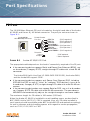
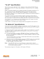
B
Port Specifications
FE Port
The 10/100 Mbps Ethernet (FE) port is located on the right-hand side of the Aruba
AP 60/61 and has an RJ-45 female connector. The port pin-outs are shown in
Figure B-1:
Aruba 60/61
10/100 Mbps Ethernet
RJ-45 Female
Pin-Out
1
2
3
4
5
6
7
8
Direction
Input
Output
FIGURE B-1
ETH Tx+
ETH Tx–
ETH Rx+
Serial RxD**
Serial RGND**
ETH Rx–
Serial TxD**
Serial TGND**
(POE negative*)
(POE negative*)
(POE positive*)
(POE positive*)
(POE positive*)
(POE negative*)
*POE optional
**Serial optional
Aruba AP 60/61 FE Port
The appropriate cable depends on the level of connectivity required of the FE port:
z
If the connecting device supports Serial and Power Over Ethernet (SPOE), use
an 8-conductor, Category 5 UTP, straight-through FE cable with a male RJ-45
connector.
The Aruba 5000 (with Line Card LC-5000-24FE-2GE-SPOE), the Aruba 2400,
and the Aruba 800 support SPOE.
z
z
If the connecting device supports only Power Over Ethernet (POE, including
IEEE 802.3af POE as well as “inline” or “midspan” POE devices), use an 8- or
4-conductor, Category 5 UTP, straight-through FE cable with male RJ-45 connectors.
If the connecting device does not support Serial or POE, use a 4- or 8-conductor, Category 5 UTP, FE cable with male RJ-45 connectors. The port detects
MDI/MDX and automatically adjusts for straight-through or crossover cables.
The maximum length for FE cables is 100 meters (325 feet).
When the Aruba AP 60/61 is installed in an air-handling space, as described in
NEC (2002) Article 300.22 (C), POE is required. Also, any FE cable installed in
such spaces should be suitable under NEC Article 800.50 and marked accordingly
for use in plenums and air-handling spaces with regard to smoke propagation,
such as CL2-P, CL3-P, MPP or CMP.
Aruba AP 60/61
Installation Guide
37
Port Specifications
Appendix B
Install cables in accordance with all applicable local regulations and practices.
Serial Breakout Adapter
The optional serial breakout adapter is used to separate the serial
communications lines from the Aruba AP 60/61 FE+SPOE port. This allows the
administrator to connect a local serial console directly to the AP and access the
apboot prompt for manual provisioning.
The serial breakout adapter pin-outs are shown in Figure B-2:
DB-9 Female Pin-Out
9
8
7
6
5
4
3
2
1
Internal Adapter Wiring
SG
Direction
Input
Output
TxD
RxD
To Console
123456789
RJ-45 Male "To AP" Pin-Out
1
2
3
4
5
6
7
8
ETH Rx+
ETH Rx–
ETH Tx+
Serial TxD
Serial TGND
ETH Tx–
Serial RxD
Serial RGND
(POE negative)
(POE negative)
(POE positive)
12345678
"To AP"
(POE positive)
RJ-45 Male "To Network" Pin-Out
1
2
3
4
5
6
7
8
FIGURE B-2
ETH Tx+
ETH Tx–
ETH Rx+
(POE negative)
(POE negative)
(POE positive)
ETH Rx–
(POE positive)
12345678
"To Network"
Aruba Serial Breakout Adapter
DB-9 Specification
The DB-9 connector attaches to the serial port of a console terminal.
Communication settings for the port are specified in Table B-1:
TABLE B-1
38
Console Terminal Settings
B a u d R a te
D a t a B it s
P a r it y
S t o p B it s
F lo w C o n t r o l
9600
8
None
1
None
Aruba AP 60/61
Installation Guide
0500160
December 2005
Port Specifications
Appendix B
“To AP” Specifications
The RJ-45 connector labeled “To AP” attaches to the Aruba AP 60/61 FE port
either directly (if the AP is physically available) or indirectly (if the AP is already
deployed).
When connecting indirectly, use a straight-through FE coupler to attach the “To
AP” connector to the FE cable leading directly to the AP’s FE port with no
intervening hubs, routers, or other network equipment. The cable must be
8-conductor, Category 5 UTP, straight-through FE cable with a maximum length of
100 meters (325 feet).
The Aruba AP 60/61 and serial breakout adapter are plenum rated. When is
installed in an air-handling space, as described in NEC (2002) Article 300.22(C),
any connecting FE cable should be suitable under NEC Article 800.50 and marked
accordingly for use in plenums and air-handling spaces with regard to smoke
propagation, such as CL2-P, CL3-P, MPP or CMP.
Install cables in accordance with all applicable local regulations and practices.
“To Network” Specifications
The RJ-45 connector labeled “To Network” attaches to an FE LAN segment. This
connection is optional unless IEEE 802.11af Power Over Ethernet (POE) is used to
power the AP during manual provisioning.
A straight-through FE coupler may be used to attach the “To Network” connector
to a LAN FE cable. The appropriate cable depends on the level of connectivity
required of the FE port:
z
If the connecting device supports IEEE 802.3af Power Over Ethernet (POE),
use a 4- or 8-conductor, Category 5 UTP, straight-through FE cable with male
RJ-45 connectors.
The Aruba 5000 (with Line Card LC-5000-24FE-2GE-SPOE), the Aruba 2400,
and the Aruba 800 support SPOE.
z
Otherwise, use a 4- or 8-conductor, Category 5 UTP, FE cable with male RJ-45
connectors. The port detects MDI/MDX and automatically adjusts for
straight-through or crossover cables.
NOTE:
Only IEEE 802.3af Power Over Ethernet is supported for manual
provisioning. “Inline” or “midspan” POE devices will not work with the
Aruba serial breakout adapter.
The maximum length for FE cables is 100 meters (325 feet).
Aruba AP 60/61
Installation Guide
39
Port Specifications
Appendix B
The Aruba AP 60/61 and serial breakout adapter are plenum rated. When is
installed in an air-handling space, as described in NEC (2002) Article 300.22(C),
the connecting FE cable should be suitable under NEC Article 800.50 and marked
accordingly for use in plenums and air-handling spaces with regard to smoke
propagation, such as CL2-P, CL3-P, MPP or CMP.
Install cables in accordance with all applicable local regulations and practices.
40
Aruba AP 60/61
Installation Guide
0500160
December 2005
C
Product Specifications
Compliance
This section lists compliance information on a country-by-country basis.
United States
The following compliance statements apply for use of this product in the United
States.
FCC - Class B
This equipment has been tested and found to comply with the limits for a Class B
digital device, pursuant to part 15 of the FCC Rules. These limits are designed to
provide reasonable protection against harmful interference in a residential
installation. This equipment generates, uses, and can radiate radio frequency
energy and, if not installed and used in accordance with the instructions, may
cause harmful interference to radio communications. However, there is no
guarantee that interference will not occur in a particular installation. If this
equipment does cause harmful interference to radio or television reception, which
can be determined by turning the equipment off and on, the user is encouraged to
try to correct the interference by one or more of the following measures:
Reorient or relocate the receiving antenna.
Increase the separation between the equipment and receiver.
Connect the equipment into an outlet on a circuit different from that to which
the receiver is connected.
Consult the dealer or an experienced radio/TV technician for help.
Any changes or modifications not expressly approved by the party responsible for
compliance could void the user’s authority to operate this equipment.
Aruba AP 60/61
Installation Guide
41
Product Specifications
Appendix C
RF Radiation Exposure Statement
This equipment complies with FCC RF radiation exposure limits set forth for fixed
indoor use only. This equipment should be installed and operated with a minimum
distance of 38.5 centimeters (15.2 inches) between the radiator and your body for
2.4 GHz and 5 Ghz operations. This transmitter must not be co-located or
operating in conjunction with any other antenna or transmitter.
Radio Frequency Interference Requirements
This device is restricted to indoor use due to its operation in the 5.15 to 5.25 GHz
frequency range. The FCC requires this product to be used indoors to reduce the
potential for harmful interference to co-channel Mobile Satellite systems. High
power radars are allocated as primary users of the 5.25 to 5.35 GHz and 5.65 to
5.85 GHz bands. These radar stations can cause interference with and/or damage
this device.
Canada
This digital apparatus does not exceed the Class B limits for radio noise emissions
from digital apparatus as set out in the interference-causing equipment standard
entitled “Digital Apparatus,” ICES-003 of the Department of Communications.
Cet appareil numérique respecte les limites de bruits radioélectriques applicables
aux appareils numériques de Classe B prescrites dans la norme sur le matériel
brouilleur: “Appareils Numériques,” NMB-003 édictée par le ministère des
Communications.
The use of this device operating either partially or completely outdoors may
require the user to obtain a license for the system according to the Canadian
regulations. For further information, contact your local Industry Canada office.
RSS-210
This device, when operated in the 5150-5250 MHz frequency range, is only for
indoor use.
CAUTION:
High power radars are allocated as primary users (meaning
they have priority) in the 5250-5350 MHz and 5650-5850
MHz frequency ranges, and these radars could cause
interference and/or damage to LE-LAN devices.
RSS-Gen
This device has been designed to operate with the antennas listed at Table 3-1 on
page 23, and having a maximum gain of 15.0dBi for 2.4GHz and 14.0dBi for
5GHz. Antennas not included in this list or having a gain greater than 15.0dBi for
2.4GHz and 14.0dBi for 5GHz are strictly prohibited for use with this device. The
required antenna impedance is 50 Ohms.
42
Aruba AP 60/61
Installation Guide
0500160
December 2005
Product Specifications
Appendix C
To reduce potential radio interference to other users, the antenna type and its gain
should be so chosen that the equivalent isotropically radiated power (EIRP) is not
more than that permitted for successful communication.
Operation is subject to the following two conditions: (1) this device may not
cause interference, and (2) this device must accept any interference, including
interference that may cause undesired operation of the device.
Japan
Indoor Restriction for 5GHz Frequency Range
VCCI - Class B
Europe
WARNING: This is a Class B product. In a domestic environment, this
product may cause radio interference in which case the user may be
required to take adequate measures.
This product complies with Directive 1999/5/EC as well as with EN5022 Class B
and EN5024 standards.
Underwriter Labs
These products have been Listed and tested for fire resistant and
low-smoke-producing characteristics, and are suitable for use in environmental air
space, such as above suspended ceilings, in accordance with Section 300-22(C)
of the National Electrical Code, and Sections 2-128, 12-010(3) and 12-100 of the
Canadian Electrical Code, Part 1, CSA C22.1.
Aruba AP 60/61
Installation Guide
43
Product Specifications
Appendix C
Peut être utilisé dans des gaines transportant de l’air traité, conformément à la
section 300-22(c) du National Electrical Code et aux articles 2-128, 12-010(3) et
12-100 du Code Canadien de l’électricité, Première partie, CSA C22.1.
EMC Compliance and Warning Statement
This equipment has been tested and found to comply with the limits of the
standard for medical devices, IEC 60601-1-2:2001. The unit also complies with
the requirements of EN 60601-1-2:1998, providing the presumption of
compliance to the European Union’s Medical Device Directive 93/42/EEC. The
limits are designed to provide reasonable protection against harmful interference
in a typical medical installation. This equipment generates, uses and can radiate
radio frequency energy, and, if not installed and used in accordance with the
manufacturer’s instructions may cause harmful interference to other devices in
the vicinity. However, there is no guarantee that interference will not occur in a
particular installation. If this equipment causes interference with other devices,
which may be determined by turning the equipment off and on, the user is
encouraged to try and correct the interference by one or more of the following
measures:
44
Reorient or relocate the device receiving the interference.
Increase the separation between the equipment.
Connect the equipment into an outlet on a circuit different from that to which
the other device(s) are connected.
Consult the manufacturer or field service technician for help.
Aruba AP 60/61
Installation Guide
0500160
December 2005
Product Specifications
Appendix C
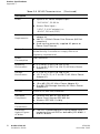
Certifications
Item
Measurement
Electromagnetic
Compatibility
FCC Part 15 Class B, FCC Part 15 Class C
(15.207/15.247)
FCC Part 15 Class E 15.407
RSS 210 (CAN)
ICES-003 Class B
VCCI Class B
TELEC ARIB STD-T66
AS/NZS 3548 Class B
EN 61000-3, EN 61000-4-2, EN 61000-4-3,
EN 61000-4-4, EN 61000-4-5, EN 61000-4-6,
EN 61000-4-8, EN 61000-4-11, EN 55022, EN 55024
IEC 60601-1-2:2001(AP 60)
EN 60601-1-2:2001 (AP 60)
The CE approval mark on back of the
product indicates that it meets
European Directives 73/23/EEC and
89/336/EEC
R&TTE Directive:
EN 300 328, EN 301 489, EN 301 893
Medical Directive:
EN 60601-1-2
Safety
UL Listed (UL60950)
UL Listed (Canadian Electrical Code/CSA 22.2 No.
60950)
EN60950 / IEC60950
National Electrical Code Section 300-22(C)
Canadian Electrical Code, Part 1, CSA C22.1 Sections
2-128, 12-010(3), and 12-100
IEC 60601-1:1988 and Amendments 1 and 2
EN 60601-1-1:2001
UL 2043
Aruba AP 60/61
Installation Guide
45
Product Specifications
Appendix C
Product Label
The product label is affixed to the chassis of the Aruba AP 60/61 The symbols on
the label are explained in this chapter.
Product Features
z
z
Wireless dual-band transceiver
Varied antenna options:
z
The Aruba AP60 has dual Reverse Polarity SMA (RP-SMA) antenna
connectors that accept a variety of high-gain detachable antennas (not
included).
z
z
z
z
z
z
z
The Aruba AP61 has a built-in swivel array with dual, tri-band,
omnidirectional antennas for reception diversity.
Protocol-independent networking functionality
Supports IEEE 802.11a or IEEE 802.11b/g operation as an AP
Supports IEEE 802.11a and IEEE 802.11b/g operation as an AM
Compatible with IEEE 802.3af Power Over Ethernet (POE)
Seamless connectivity to wired LANs augment existing networks quickly and
easily
Can be centrally managed, configured, and upgraded through the Mobility
Controller to take advantage of network changes and security improvements
Ethernet Compatibility
The Aruba AP 60/61 attaches to 10/100 Mbps Ethernet (FE) LAN segments that
utilize 10Base-T/100Base-TX (twisted-pair) wiring. The device appears as an
Ethernet node and performs a routing function by moving packets between the
wired LAN and remote workstations on the wireless infrastructure.
Radio Characteristics
The Aruba AP 60/61 can be configured to support IEEE 802.11a or IEEE
802.11b/g operation as an AP, and supports both IEEE 802.11a and IEEE
802.11b/g operation as an AM:
z
802.11a provides a high data rate and reliable wireless connectivity
802.11a operation uses a radio modulation technique known as Orthogonal
Frequency Division Multiplexing (OFDM), and a shared collision domain
(CSMA/CA). It operates in the 5GHz Unlicensed National Information
Infrastructure (UNII) band. Data is transmitted over a half-duplex radio channel
operating at up to 54 Megabits per second (Mbps).
z
46
802.11b provides an alternative to wired LANs that can dramatically cut costs
Aruba AP 60/61
Installation Guide
0500160
December 2005
Product Specifications
Appendix C
802.11b operation uses the IEEE 802.11 High-Rate Direct Sequence (HRDS)
specification, and a shared collision domain (CSMA/CA). It operates in the
2.4GHz Industrial/Scientific/Medical (ISM) band. The ISM band is available
worldwide for unlicensed use. Data is transmitted at speeds of up to 11
Mbps.
z
802.11g provides a high data rate and is backwards compatible with 802.11b.
802.11g operation uses ODFM and a shared collision domain (CSMA/CA). It
operates in the 2.4GHz Industrial/Scientific/Medical (ISM) band. The ISM band
is available worldwide for unlicensed use. Data is transmitted at speeds of up
to 54 Mbps.
Power Over Ethernet
The Aruba AP 60/61 supports the IEEE 802.3af standard for Power Over Ethernet
(POE). With this feature, the Aruba AP 60/61 can accept electrical power from a
compatible POE-capable device (such as the Aruba 5000 (with Line Card
LC-5000-24FE-2GE-SPOE), Aruba 2400, or Aruba 800) directly over the FE cable.
POE eliminates the need to provide separate power outlets in environments that
are difficult or undesirable to wire for electricity.
The Aruba AP 60/61 also supports “inline” and “midspan” POE devices for
normal operation. Inline power is POE that is integrated into FE ports and provides
POE directly to devices. Non-POE ports can have POE added by means of a
mid-span device that provides POE. The non-POE port is connected to a mid-span
POE port, and this mid-span port is connected to the device that requires POE.
Physical Description
Package Contents
The Aruba AP 60/61 package includes:
z
z
One Aruba AP 60/61 Access Point
Assorted documentation
Inform your supplier if there are any incorrect, missing or damaged parts. If
possible, retain the carton, including the original packing materials. Use them to
repack the product in case there is a need to return it.
Optional Items
The following optional items can also be ordered for the Aruba AP 60/61:
z
z
Detachable antennas (Aruba AP60 only)
AC power adapter (5 VDC, 3 A) and power cord
Aruba AP 60/61
Installation Guide
47
Product Specifications
Appendix C
z
z
Serial breakout adapter for direct access to the AP console
Mounting kit (modular cradle for walls and suspended ceilings)
Check with your Aruba sales representative for the availability of optional items.
The following specifications apply to the Aruba AP60 and Aruba AP61 Access
Points.
Aruba AP-60 Access Point
FIGURE C-1 Part Number: AP-60
48
Aruba AP 60/61
Installation Guide
0500160
December 2005
Product Specifications
Appendix C
TABLE C-1 AP-60 802.11 Specifications
Description
802.11a
802.11b
802.11g
Antenna
Dual, diversity supporting Reverse Polarity-SMA (RP-SMA)
detachable antenna interfaces suitable for acceptance of
single-band or tri-band 802.11a/b/g detachable antennas
of various pattern types and gain. For information on
third-party antennas, go to the Interoperability section of
the Products page at:
http://www.arubanetworks.com
Frequency
Band
z
z
5.250 ~
5.350Ghz
(middle band)
4 channels
5.725 ~
5.825Ghz
(higher band)
4 channels
z
z
2.4 ~
2.483Ghz (US,
Canada &
ETSI)
2.4 ~
2.497Ghz
(Japan)
Complete country
list available at
http://
www.arubanetwo
rks.
com/products/aps
/
certification
z
z
z
2.412 ~
2.462Ghz (US,
Canada)
2.412 ~
2.472Ghz
(ETSI)
2.412 ~
2.484Ghz
(Japan)
Complete country
list available at
http://
www.arubanetw
orks.
com/products/ap
s/
certification
Radio
Technology
Orthogonal
Frequency
Division
Multiplexing
(OFDM)
Direct Sequence
Spread Spectrum
(DSSS)
Orthogonal
Frequency
Division
Multiplexing
(OFDM)
Modulation
Type
BPSK, QPSK,
16-QAM,
64-QAM
CCK, BPSK,
QPSK
CCK, BPSK,
QPSK, 16-QAM,
64-QAM
Transmit
Power
Configurable by
system
administrator/
professional
installer
Configurable by
system
administrator/
professional
installer
Configurable by
system
administrator
Aruba AP 60/61
Installation Guide
49
Product Specifications
Appendix C
TABLE C-1 AP-60 802.11 Specifications
Description
802.11a
802.11b
802.11g
Media
Access
Control
CSMA/CA with
ACK
CSMA/CA with
ACK
CSMA/CA with
ACK
Operating
Channels
z
z
z
z
z
Data Rates
50
(Continued)
Aruba AP 60/61
Installation Guide
US & Canada: 8
ETSI: 13
Japan: 5
z
z
US & Canada:
11
ETSI: 13
Japan: 13
z
z
US & Canada:
11
ETSI: 13
Japan: 13
Complete
country list
available at
http://
www.arubanetw
orks.com/produc
ts/aps/certificatio
n
Complete country
list available at
http://
www.arubanetwo
rks.com/products
/aps/
certification
Complete country
list available at
http://
www.arubanetw
orks.
com/products/ap
s/
certification
6, 9, 12, 18, 24,
36, 48, 54 Mbps
per channel
1, 2, 5.5, 11 Mbps
per channel
6, 9, 12, 18, 24,
36, 48, 54 Mbps
per channel
0500160
December 2005
Product Specifications
Appendix C
TABLE C-2 AP-60 Characteristics
Description
Maximum
Clients
64
Multi-mode
Radio Band
Selectable via software
Manageability:
z
z
Management of all 802.11 parameters
Network Wide AP Management via:
CLI
WEB GUI
SNMPv3
z
Access Point Profiles, Management by:
Geographical Location
BSSID
Radio Type
Encryption
Support (AP and
Mobility
Controller)
40bit / 64bit / 128bit / 152bit WEP, TKIP, AES
Physical
(HxWxD):
z
z
159 x 99 x 31 mm / 6.26 x 3.90 x 1.22 ina
Weight 198 grams / 7 oz
Interfaces
(Electrical):
z
1 x 10/100 Base-TX auto-sensing Ethernet RJ-45
Interface (Auto-sensing MDI/MDX)
Serial and Power Over Ethernet - 48V DC / 200mA
Power Over Ethernet (802.3af compliant)
1 x 5V DC Power Interface
z
z
Interfaces
(Mechanical):
z
z
Visual Indicators
(LEDs)
Standard Kensington MicroSaver Security Cable
Interface (cable not supplied)
Wall and ceiling mount kit (optional - part number
AP-60-MNT) interface
Ready -- Power
Ethernet link status / Activity
WLAN Activity
Aruba AP 60/61
Installation Guide
51
Product Specifications
Appendix C
TABLE C-2 AP-60 Characteristics
(Continued)
Description
Power
z
Optional AC Power Adapter Input—
100-240 AC, 50-60 Hz
z
Access Point Input—
5 VDC, 3 A (AC adapter), or
48 VDC, 200 mA (POE)
Power
Requirements
z
z
z
52
5V DC / 2A supplied externally via optional AC
adapter kit
48V DC / 200mA Power Over Ethernet (802.3af
compliant)
Auto-sensing externally supplied AC power or
Power Over Ethernet
Output Power
100 mW maximum (or lower as configured on the
Aruba Mobility Controller to comply with local
regulatory requirements)
Power
Consumption
10W maximum
Operating
Environment
z
z
0 ºC to 50 ºC (32 ºF to 122 ºF) AP
0 ºC to 40 ºC (32 ºF to 104 ºF) AC Mains Power
Adapter Kit
Storage
Environment
z
z
0 ºC to 70 ºC (32 ºF to 158 ºF) AP
-20 ºC to 70 ºC (-4 ºF to 158 ºF) AC Mains Power
Adapter Kit
Humidity
z
z
z
5 to 95%, non-condensing AP
15 to 85% RH AC Mains Power Adapter Kit
5 to 90% RH Storage Humidity AC Mains Power
Adapter Kit
Altitude
3,048 m (10,000 feet) maximum
Standards
Compliance
z
z
z
Ethernet IEEE 802.3 / IEEE 802.3u
Power Over Ethernet IEEE 802.3af
Wireless IEEE 802.11a/b/g
Mains
Connections
z
Class II (ungrounded equipment)
Protection
Against Egress
of Water
z
The unit is protected against falling liquids with a
protection class of IPX0 as defined by IEC 60601-1
and IEC 60529.
Aruba AP 60/61
Installation Guide
0500160
December 2005
Product Specifications
Appendix C
TABLE C-2 AP-60 Characteristics
(Continued)
Description
Mode of
Operation
a.
z
As defined by IEC 60601-1, this unit is considered
“Continuous Operation” equipment.
Measurements indicate only the Access Point chassis. Size and weight do not include
other materials (such as detachable antennas, mounting kits, and cables) which may
vary
Aruba AP-61 Access Point
FIGURE C-2 Part Number: AP-61
Aruba AP 60/61
Installation Guide
53
Product Specifications
Appendix C
TABLE C-3 AP-61 802.11 Specifications
Description
802.11a
802.11b
802.11g
Antenna
Integral, diversity supporting dual, tri-band 802.11a/b/g
omni-directional high-gain antennas with 90 degrees
rotational movement
Integral antenna gain:
2.4 Ghz / 2.8dBi
5.150-5.350 Ghz / 3.9dBi
5.6 Ghz / 4 dBi
Frequency
Band
z
z
z
54
5.150 ~
5.250Ghz
(lower band)
4 channels
5.250 ~
5.350Ghz
(middle band)
4 channels
5.725 ~
5.825Ghz
(higher band)
4 channels
z
z
2.4 ~
2.483Ghz
(US, Canada
& ETSI)
2.4 ~
2.497Ghz
(Japan)
Complete country
list available at
http://
www.arubanetw
orks.com/produc
ts/aps/
certification
z
z
z
2.412 ~
2.462Ghz (US,
Canada)
2.412 ~
2.472Ghz
(ETSI)
2.412 ~
2.484Ghz
(Japan)
Complete country
list available at
http://
www.arubanetwo
rks.
com/products/aps
/
certification
Radio
Technology
Orthogonal
Frequency
Division
Multiplexing
(OFDM)
Direct Sequence
Spread Spectrum
(DSSS)
Orthogonal
Frequency
Division
Multiplexing
(OFDM)
Modulation
Type
BPSK, QPSK,
16-QAM,
64-QAM
CCK, BPSK,
QPSK
CCK, BPSK,
QPSK, 16-QAM,
64-QAM
Transmit
Power
Configurable by
system
administrator/
professional
installer
Configurable by
system
administrator/pro
fessional installer
Configurable by
system
administrator
Media Access
Control
CSMA/CA with
ACK
CSMA/CA with
ACK
CSMA/CA with
ACK
Aruba AP 60/61
Installation Guide
0500160
December 2005
Product Specifications
Appendix C
TABLE C-3 AP-61 802.11 Specifications (Continued)
Description
802.11a
802.11b
802.11g
Operating
Channels
z
z
z
z
US, Canada
& ETSI: 12
Japan: 5
Complete
country list
available at
http://
www.arubanetw
orks.com/produc
ts/
aps/certification
Data Rates
6, 9, 12, 18, 24,
36, 48, 54 Mbps
per channel
z
z
US & Canada: 11
ETSI: 13
Japan: 13
z
z
US & Canada:
11
ETSI: 13
Japan: 13
Complete country
list available at
http://
www.arubanetw
orks.com/produc
ts/aps/
certification
Complete country
list available at
http://
www.arubanetwo
rks.
com/products/aps
/
certification
1, 2, 5.5, 11
Mbps per
channel
6, 9, 12, 18, 24,
36, 48, 54 Mbps
per channel
TABLE C-4 AP-61 Characteristics
Description
Maximum
Clients
64
Multi-mode
Radio Band
Selectable via software
Manageability:
z
z
Management of all 802.11 parameters
Network Wide AP Management via:
CLI
WEB GUI
SNMPv3
z
Access Point Profiles, Management by:
Geographical Location
BSSID
Radio Type
Aruba AP 60/61
Installation Guide
55
Product Specifications
Appendix C
TABLE C-4 AP-61 Characteristics (Continued)
Description
Encryption
Support (AP
and Mobility
Controller)
40bit / 64bit / 128bit / 152bit WEP, TKIP, AES
Physical
(HxWxD):
z
z
z
z
Interfaces
(Electrical):
z
z
z
Interfaces
(Mechanical):
Antenna up, stand closed—216 x 99 x 31 mm /
8.50 x 3.90 x 1.22 ina
Antenna up, stand open—209 x 99 x 74 mm /
8.23 x 3.90 x 2.91 in
Antenna 90o, stand closed— 159 x 99 x 71 mm /
6.26 x 3.90 x 2.80 in
Weight 255 grams / 9 oz
1 x 10/100 Base-TX auto-sensing Ethernet
RJ-45
Interface (Auto-sensing MDI/MDX)
Serial and Power Over Ethernet - 48V DC /
200mA Power Over Ethernet (802.3af compliant)
1 x 5V DC Power Interface
Standard Kensington MicroSaver Security Cable
Interface (cable not supplied)
Wall and ceiling mount kit (optional - part number
AP-60-MNT) interface
Visual Indicators
(LEDs)
Ready -- Power
Ethernet link status / Activity
WLAN Activity
Power
z
Optional AC Power Adapter Input—
100-240 AC, 50-60 Hz
z
Access Point Input—
5 VDC, 3 A (AC adapter), or
48 VDC, 200 mA (POE)
Power
Requirements
z
z
z
56
Aruba AP 60/61
Installation Guide
5V DC / 2A supplied externally via optional AC
adapter kit
48V DC / 200mA Power Over Ethernet (802.3af
compliant)
Auto-sensing externally supplied AC power or
Power Over Ethernet
0500160
December 2005
Product Specifications
Appendix C
TABLE C-4 AP-61 Characteristics (Continued)
Description
Output Power
100 mW maximum (or lower as configured on the
Aruba Mobility Controller to comply with local
regulatory requirements)
Power
Consumption
10W maximum
Operating
Environment
z
z
0 ºC to 50 ºC (32 ºF to 122 ºF) AP
0 ºC to 40 ºC (32 ºF to 104 ºF) AC Mains Power
Adapter Kit
Storage
Environment
z
z
0 ºC to 70 ºC (32 ºF to 158 ºF) AP
-20 ºC to 70 ºC (-4 ºF to 158 ºF) AC Mains Power
Adapter Kit
Humidity
z
z
z
5 to 95%, non-condensing AP
15 to 85% RH AC Mains Power Adapter Kit
5 to 90% RH Storage Humidity AC Mains Power
Adapter Kit
Altitude
3,048 m (10,000 feet) maximum
Standards
Compliance
z
z
z
a.
Ethernet IEEE 802.3 / IEEE 802.3u
Power Over Ethernet IEEE 802.3af
Wireless IEEE 802.11a/b/g
Measurements indicate only the Access Point chassis. Size and weight do not include other materials (such as detachable antennas, mounting kits, and cables)
which may vary
Related Documents
The following items are part of the complete documentation for the Aruba
system:
z
z
z
z
Aruba Quick Start Guide
Aruba AP 60/61 Wireless Access Point Installation Guide (this document)
ArubaOS User Guide
Aruba Mobility Controller installation guide
For the current versions of these manuals, or to obtain the latest product release
notes, visit the support section of the Aruba Web site (see page 60).
Aruba AP 60/61
Installation Guide
57
Product Specifications
Appendix C
Text Conventions
The following conventions are used throughout this manual to emphasize
important concepts:
TABLE C-5 Text Conventions
Type Style
Description
Italics
This style is used to emphasize important terms and to
mark the titles of books.
System items
This fixed-width font depicts the following:
z
z
z
Sample screen output
System prompts
Filenames, software devices, and certain commands
when mentioned in the text.
Commands
In the command examples, this bold font depicts text
that the user must type exactly as shown.
<Arguments>
In the command examples, italicized text within angle
brackets represents items that the user should replace
with information appropriate to their specific situation.
For example:
# send <text message>
In this example, the user would type “send” at the
system prompt exactly as shown, followed by the text of
the message they wish to send. Do not type the angle
brackets.
58
[ Optional ]
In the command examples, items enclosed in brackets
are optional. Do not type the brackets.
{ Item A | Item B }
In the command examples, items within curled braces
and separated by a vertical bar represent the available
choices. Enter only one choice. Do not type the braces or
bars.
Aruba AP 60/61
Installation Guide
0500160
December 2005
Product Specifications
Appendix C
TABLE C-5 Text Conventions (Continued)
NOTE:
Useful tips or information about the topic under
discussion.
Indicates that protection against electrical shock is
required. This symbol indicates that a danger to personal
safety exists.
Indicates caution is required. Failure to heed these
cautions may result in damaged equipment or loss of
data.
Aruba AP 60/61
Installation Guide
59
Product Specifications
Appendix C
Contacting Aruba Networks
Web Site
Main Site
http://www.arubanetworks.com
Support
http://www.arubanetworks.com/support
E-mail
Sales
[email protected]
Support
[email protected]
Telephone Numbers
60
Main
408-227-4500
Fax
408-227-4550
Sales
408-754-1201
Support
In the US:
800-WI-FI-LAN (800-943-4526)+
France:
33 (0) 170725559+44 (0)
UK:
2071275989+49 (0)
Germany:
69380977228+ 00 1
All Other:
408-754-1200
Aruba AP 60/61
Installation Guide
0500160
December 2005
Product Specifications
Appendix C
Proper Disposal of Aruba Equipment
This product at end of life is subject to separate collection and
treatment in the EU Member States, Norway, and Switzerland
and therefore is marked with the symbol shown at the left.
Treatment applied at end of life of these products in these
countries shall comply with the applicable national laws
implementing Directive 2002/96EC on Waste of Electrical and
Electronic Equipment (WEEE).
The WEEE Directive 2002/96/EC and RoHS (Restriction of
Hazardous Substances) Directive 2002/95/EC sets collection,
recycling and recovery targets for various categories of
electrical products and their waste.
The Restriction on Hazardous Substances Directive (RoHS)
(2002/95/EC), which accompanies the WEEE Directive, bans
the use of heavy metals and brominated flame-retardants in
the manufacture of electrical and electronic equipment.
Specifically, restricted materials under the RoHS Directive are
Lead (including Solder used in PCB's), Cadmium, Mercury,
Hexavalent Chromium, and Bromine.
Aruba declares compliance with the European Union (EU)
WEEE Directive (2002/96/EC). For more information on WEEE,
refer to:
http://www.dti.gov.uk/sustainability/weee/
Aruba AP 60/61
Installation Guide
61
Product Specifications
Appendix C
62
Aruba AP 60/61
Installation Guide
0500160
December 2005
Notes
Aruba AP 60/61
Installation Guide
63
Notes
132 2 c r o s s m a n a v e n u e
sunny vale california 94089
tel 408 227 4500 fax 408 227 4550
w w w.arubanet works.com
64
Aruba AP 60/61
Installation Guide
0500160
December 2005