1
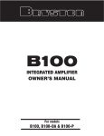
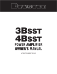
OWNER’S MANUAL
Instructions For
Bryston PreAmplifiers
Models BP20 & BP25
IMPORTANT SAFETY INSTRUCTIONS
The lightning flash with arrowhead symbol within an equilateral triangle, is intended to
alert the user to the presence of uninsulated "dangerous voltage " within the product's
enclosure that may be of sufficient magnitude to constitute a risk of electric shock to persons.
The exclamation point within an equilateral triangle is intended to alert the user to the
presence of important operating and maintenance (servicing) instructions in the literature
accompanying the product.
1.
2.
3.
4.
5.
6.
7.
8.
9.
10.
11.
12.
13.
14.
Read these instructions.
Keep these instructions.
Heed all warnings.
Follow all instructions.
Do not use this apparatus near water.
Clean only with dry cloth.
Do not block any ventilation openings. Install in accordance with the manufacturer's instruc
tions.
Do not install near any heat sources such as radiators, heat registers, stoves, or other appara
tus (including amplifiers) that produce heat.
Do not defeat the safety purpose of the polarized or grounding-type plug. A polarized plug has
two blades with one wider than the other. A grounding type plug has two blades and a third
grounding prong. The wide blade or the third prong are provided for your safety. If the provid
ed plug does not fit into your outlet, consult an electrician for replacement of the obsolete out
let.
Protect the power cord from being walked on or pinched particularly at plugs, convenience
receptacles, and the point where they exit from the apparatus.
Only use attachments/accessories specified by the manufacturer.
Use only with the cart, stand, tripod, bracket, or table specified by the manufacturer,
or sold with the apparatus. When a cart is used use caution when moving the
cart/apparatus combination to avoid injury from tip-over.
Unplug this apparatus during lightning storms or when unused for long periods of time.
Refer all servicing to qualified service personnel. Servicing is required when the apparatus has
been damaged in any way, such as power-supply cord or plug is damaged, liquid has been
spilled or objects have fallen into the apparatus, the apparatus has been exposed to rain or
moisture, does not operate normally, or has been dropped.
"WARNING: TO REDUCE THE RISK OF FIRE OR ELECTRIC SHOCK, DO NOT EXPOSE THIS
APPARATUS TO RAIN OR MOISTURE".
"DO NOT EXPOSE THIS EQUIPMENT TO DRIPPING OR SPLASHING AND ENSURE THAT NO
OBJECTS FILLED WITH LIQUIDS, SUCH AS VASES, ARE PLACED ON THE EQUIPMENT".
"TO COMPLETELY DISCONNECT THIS EQUIPMENT FROM THE AC MAINS, DISCONNECT THE
POWER SUPPLY CORD PLUG FROM THE AC RECEPTACLE".
"THE MAINS PLUG OF THE POWER SUPPLY CORD SHALL REMAIN READILY OPERABLE".
BP20/25 PreAmplifiers
All fuses are 5mm x 20mm, time lag type and are accessible only by removing the top cover. When replacing
fuses, disconnect the power cord before opening the unit!
General Specifications:
Frequency Response:
20Hz-20kHz +/- .05dB
Recommended replacement fuses:
for 100/120VAC models:
Littlefuse 218.315
Bussmann GMC-315mA
for 230/240VAC models:
Littlefuse 218.160
Bussmann GMC-160mA
Maximum Output:
15 volts unbalanced, 30 volts balanced
IMD/THD:
<0.0015% at 3 volts out
Sensitivity:
Balanced inputs:
UnBalanced line level inputs:
Additional Specifications for BP20/25DA:
1.00 V
500 mV
Input Sample Rate:
Word Length:
Data format:
Distortion:
Signal to Noise Ratio:
Frequency Response:
Rated Noise:
-100dB (Ref. 500mV unbalanced input, 20-20kHz)
-103dB (Ref. 1 volt balanced input 20-20kHz)
XLR Connector Pin out (Balanced I/O):
Pin 1 ground, pin 2 positive, pin 3 negative
Features:
2 pair balanced female XLR inputs
1 pair balanced male XLR outputs
5 pair RCA inputs
4 pair RCA + 1 pair phono inputs (BP-20/25P and BP20/25MC only)
4 pair RCA + 2 SPDIF digital inputs (BP20/25 DA only)
2 pair RCA outputs
1 tape loop
Rack mount version:
Weight:
<0.005%, IM or THD, any frequency or combination of frequencies from 20-20kHz, at rated output or below.
Rated Noise:
Phono: -80dBA referred to an input of 5 millivolts RMS @
1kHz
Input sensitivity:
5mV
Additional Specifications for BP-25MC
Phono Inputs:
Distortion:
<0.005%, 20-20kHz, with preamplifier driven to full rated
output
17” x 1.75” x 11”
43.18cm x 4.44cm x 28cm
19” x 1.75” x 11”
48.26cm x 4.44cm x 28cm
Noise:
Equivalent to approximately 1000 ohm metal film register
(Thermal noise greater than 85dB below 0.6mV input,
unweighted)
17 lbs (7.5 kg)
Gain: 16.5 or 22.5dB (internally reconfigurable)
MPS-1 POWER SUPPLY SPECIFICATIONS:
Dimensions: 7.75” x 4.525” x 2.36”h
Weight:
2.6 lb. (1182g)
Electrical: 120VAC/60Hz/29VA, Fuse: 315mA/250V time lag
230VAC/50Hz/29VA, Fuse: 160mA/250V time lag
240VAC/50Hz/29VA, Fuse: 160mA/250V time lag
Output:
Additional Specifications for BP20/25P
Phono Inputs:
Distortion:
RIAA Accuracy:
Within less than +/- 0.05dB from 20-20kHz inclusive
Options:
Silver faceplate & hand held remote (std. is black)
19” x 1.75” Rack mount faceplate (std. 17” long)
Moving magnet RIAA phono equalization module
Moving coil & moving magnet RIAA phono EQ
module
Digital audio input (SPDIF) module
Dimensions:
Standard version:
16kHz to 108kHz.
16, 18, 20, 24 Bit
SPDIF standard
< 0.002%, 20Hz-20kHz
> 100dB
20Hz-20kHz +/- .1dB
Frequency Response: Below 5Hz to above 30kHz, within
less than +/- 0.5dB
Input sensitivity:
350uV (0.35mV)
+/-28VDC @ 350mA (56VDC @ 700mA)
Sept 2003
2
BP20/25 PreAmplifiers
INTRODUCTION
Thank you for choosing a Bryston PreAmplifier. Bryston
welcomes any suggestions you may have, or comments
regarding the operation of your amplifier. We consider you,
our customer, to be Bryston’s most important resource, and
your opinion is very much appreciated.
SETUP:
To turn on a Bryston amplifier by turning on the MPS-1:
1st) Connect the COM and +12V terminals of the three ter
minal connector on the rear panel of the MPS-1 to the
IN terminals on a Bryston power amplifier intended for
a 4~14V AC/DC control signal.
2nd) Put the amplifiers “EXTERNAL TURN ON” switch in the
EXTERNAL position for the amplifier to respond to
remote control turn-on signals (see figure 2).
The Bryston BP-25 pre-amps, with remote-control, should
be placed where there is a direct line-of-sight between the
hand-held remote and the remote infra-red sensor eye
located on the left side of the pre-amplifier's front panel.
If you purchased the BP0/25P or BP20/25MC, which
includes a Phono section, avoid placing the preamplifier
directly on top of your power amplifier. Power amplifiers usually employ large power supplies and the transformer(s) in
the power supplies can cause interference (hum) with the
sensitive phono section inside the pre-amp.
Next, insert the 5-pin DIN cable from the outboard
power supply into the “Power Supply” input connector ( 5 pin
DIN) located on the rear of the preamplifier. Then plug the
power supply into an appropriate AC power outlet. The preamplifier is powered up by engaging the push button switch Figure 1: Turning “SST” power amps on & off via the MPS1 power supply
located on the front of the MPS-1 external power supply.
The "green" LED on the outboard power supply and the pre- To turn a Bryston power amplifier OFF and ON when the
amplifier front panel indicates power-on.
BP20/25 pre-amp is MUTED and unMUTED respectively:
1st) Connect the +12V SW and COM terminals on the
EXTERNAL POWER SUPPLY (MPS-1) and REMOTE
back of the MPS-1 to the two IN terminals on the power
TURN-ON FUNCTIONS:
amp’s remote control connector.
The MPS-1 outboard power supply provides AC power for 2nd) Place the power amplifiers EXTERNAL TURN ON
the BP20 and BP25 preamplifiers. It has a push button
switch in the EXTERNAL position.
switch (push-to-set/push-to-release) located on the front
and a 2 colour LED to indicate power and mute status. This
LED mirrors the operation of the similar LED on the BP20/25
preamp (see the Visual Indicators section for more information). On the rear of the unit there are two terminal blocks
and a two position slide switch.
The two position connector, or terminal block, accepts
bare wires between 12 and 26 AWG. Insulated wires should
be stripped to expose .3 inches (5/16” or 8mm) of bare wire.
This provides a means of turning on the MPS-1 power supply (and thus the BP20/25 pre-amp) remotely by connecting
a 4 to 12 volt (AC or DC) control signal. To enable remote
turn-on, the rear panel slide switch must be in the REMOTE
position and the front push-button power switch must be
Figure 2: Turning “SST” power amps on & off via the BP20/25 MUTE switch
depressed (activated).
To operate the MPS-1 power supply manually:
1st) Put the rear panel slide switch in the LOCAL position, CONNECTIONS to OTHER EQUIPMENT:
2nd) Press in the front panel push-button switch to turn on
All inputs and outputs employ fully discrete active circuitry
the unit. Press in the push-button switch again to
and all input and output connectors have gold plated contact
release the switch and turn off the MPS-1 power sup surfaces. Only cables with high quality gold plated connecply and the BP20/25 pre-amp.
tors should be used with your pre-amp to avoid noise and
The three-position connector provides a control voltage for distortion from the corrosion that will eventually appear on
remote turn on/off of your Bryston amplifier(s) or other poorly plated cable connectors.
amplifiers so equipped.
3
BP20/25 PreAmplifiers
Connect the pre-amplifier's left and right outputs from either
the RCA or Balanced XLR connectors to the appropriate left
and right input jacks on your power amplifier. Balanced
cables are an advantage if you are using long runs of cable,
(greater than 20 feet), between your preamplifier and power
amplifier. Connect your CD player, tuner, tape deck, video
recorder, or laser disc, etc. to the specific left/right preamplifier inputs.With phono-equipped models, (BP20P, BP25P,
BP20MC, BP25MC) connect your phono cables to the
phono input jacks. If your turntable leads have a separate
ground wire, it may be connected to the ground post adjacent to the phono inputs on the rear panel.
The Bryston BP-20 and BP-25 pre-amps also feature two
pairs of balanced XLR input jacks. Many signal sources,
including CD-players and separate D/A converters are now
available with Balanced outputs for minimum noise pickup
on the cables.
The tape loop may be used to insert a surround sound
processor, cassette tape deck or video tape recorder into
your system. Plug your tape deck or external processor's
input cables into the “To Tape” jacks, and the processor or
deck's output cables into the “From Tape” jacks at the rear
of the pre-amp. The tape or processor loop may be operated via the “Tape/Source” toggle switch located on the front
panel of the preamplifier.
HEADPHONE OUTPUT:
It is recommended that you use headphones with an
impedance of greater than 50 ohms for optimal performance. The main outputs, both balanced and single-ended,
will be muted when a phone plug is inserted into the headphone jack (TAPE outputs are not muted). The front panel
indicator LED will not turn red, however, as is does when
the outputs are muted via the MUTE toggle switch or the
hand held remote control.
INPUTS:
BP20/25 preamplifiers are equipped with five pairs of RCA
input connectors: two paris of balanced XLR input connectors, and one pair of RCA tape input jacks.
Balanced inputs use 3 pin XLR female connectors with pin
1 being ground, pin 2 as positive signal, and pin 3 as negative signal. Input sensitivity is 1 volt and input impedance is
15K ohms.
Single-ended (or unbalanced) inputs employ gold plated
RCA (Phono) jacks. Line input sensitivity is 500mV and
input impedance is 50K ohms. See also PHONO EQUALIZATION MODULES for Phono input details.
OUTPUTS:
There are two pairs of parallel RCA main outputs and one
pair of RCA tape output jacks. One pair of balanced outputs,
using 3 pin male XLR jacks, are also provided.
Balanced Outputs: As with the input XLR jacks, pin 1 is
ground, pin 2 is positive and pin 3 is negative. These out-
puts are capable of driving 30 volts into any load of 600
ohms or greater. Do not short any of these three pins together!
Single-ended or unbalanced outputs: As with unbalanced inputs, these connectors are gold plated RCA
(phono) jacks. They are capable of driving 15 volts into any
load of 600 ohms or greater.
TAPE LOOP:
Tape Outputs: The “TO TAPE” outputs are selected by
the rotary ‘SOURCE” knob and are provided as a recording
output. This feed is unaffected by the operation of other
front panel controls.
Tape Inputs: The “FROM TAPE” (unbalanced RCA)
inputs are useful for monitoring tape playback or processed
signals. Moving the “Tape/Source” toggle to Tape’ (up)
position monitors the recorded signal on recorders
equipped with a separate playback head, or the processed
signal when using a signal processor. Input sensitivity is
500mv, input impedance is 10K ohms.
BP25 REMOTE CONTROL (Optional):
The Bryston model BP25 preamplifier is
supplied with a hand held infra-red
remote control unit (units without the IR
remote control are referred to as BP20
models). The remote features include
volume control, mute and polarity (or
signal phase). All remote control functions may be operated manually from
the front panel of the preamplifier if
desired.
Volume is remotely controlled via
the UP and DOWN arrow buttons. A
motorized volume control ensures the
lowest distortion with maximum long term reliability. It is also
manually accessible on the front panel.
The Phase switch (or the “Polarity/Invert” toggle switch
on the front panel) allows you to reverse the absolute phase
of the audio signal (not to be confused with the left-versusright channel phase), because polarity reversal can occur in
the recording chain. It is desirable to maintain absolute
phase as originally played in the recording hall as that will
provide the most accurate representation of the original
wave front. This may be audible in some cases as a more
realistic rendition of musical transients when the preamplifiers maintain non-inverting polarity at the Main output for all
inputs when the pilot light (or status LED) is green. The
polarity is inverted when the status LED is yellow. The “To
Tape” outputs are always non-inverted.
The Mute control mutes the main outputs (both balanced and unbalanced) of the preamplifier, but not the tape
outputs (labeled “To Tape”). Refer also to the Power Supply
section earlier in this manual for information regarding
remote amplifier control (on/off) via the mute switch.
4
BP20/25 PreAmplifiers
PHONO EQUALIZATION MODULES (Optional):
FRONT PANEL CONTROLS:
Bryston’s phono equalizer circuitry is available in both BP20
and BP25 pre-amplifiers. It features highly accurate equalization, extremely low noise and distortion and provides
headroom margins sufficient to prevent overload from any
known phono source. If your turntable provides a separate
ground lead , system noise may be minimized by connecting it to the ground post adjacent to the phono inputs on the
rear panel.
Moving Magnet Phono Cartridge Input (MM):
This is Bryston’s standard RIAA phono equalization stage. It
is found in both the “-P” and “-MC” versions of the BP20/25
pre-amp. Input impedance is 50K ohms and sensitivity is
5mV.
Moving Coil Phono Cartridge Input (MC):
Moving coil phono cartridges require much more gain than
the more common moving magnet types. To accommodate
moving coil cartridges Bryston offers the BP20MC/BP25MC
pre-amps which include specially designed, custom made
step-up transformers in addition to Bryston’s standard RIAA
phono equalization stage found in the “-P” versions of the
BP20/25 pre-amp. Which phono equalization stages are
engaged is determined by the front panel toggle switch
labeled “MC Phono / MM Phono”. This switch is not present
on the BP20P/BP25P models; it is replaced, instead with a
“Mono / Stereo” switch. Please note that it is important that
your phono cartridge is connected to the correct inputs in
order to achieve proper performance.
Input impedance is 180 ohms and sensitivity is 350uV.
MUTE/NORMAL TOGGLE SWITCH: Mutes or releases
mute at the main outputs, (not ‘To Tape’ outputs), without
changing the volume control setting, each time pushed.
DIGITAL AUDIO INPUT MODULE (Optional):
The BP20DA / BP25DA models contain two SPDIF compatible digital audio inputs. To select either the DAC-1 or
DAC-2 digital audio input, first set the rotary SOURCE
selector to DAC, and then select between the two SPDIF
inputs with the DAC-1/ DAC-2 toggle switch. The digital-toanalog convertor can handle input sample rates from
16KHz to 108KHz, and word lengths of 16, 18, 20 or 24
bits.
VISUAL INDICATORS:
MPS1 Power Supply: The LED on the front panel of the
MPS1 lights GREEN when power is on and RED when the
power is on but the main outputs are muted by having activated either the “Mute/Normal” toggle switch (on the preamp’s front panel) or the “MUTE” button on the hand held
remote control.
BP20/25: The three colour LED (light emitting diode)
located on the front panel lights RED when the output is
muted, GREEN when the output signal is non-inverting
polarity and YELLOW when the output signal is inverted
with respect to the input. When the LED is unlighted, the
power is off.
POLARITY/INVERT TOGGLE SWITCH: Reverses polarity at main output5 each time pushed. (GREEN LED indicates positive polarity, YELLOW LED indicates inverse
polarity).
VOLUME CONTROL: Rotary control varies the output
level to the ‘MAIN OUTPUTS’, (does not effect ‘TO TAPE’
outputs). BALANCE: Rotary control adjusts the left-versusright channel levels.
BALANCE CONTROL: is a tailored-inflection type which
has very gradual action near the center of rotation allowing fine adjustments to the stereo image. For convenience
the electrical center of the control is detented.
SOURCE SELECT SWITCH: Rotary switch determines
which input will appear at the “TO TAPE” outputs for
recording or processing, as well as determining which program is available at the Main outputs. (When the
“TAPE/SOURCE” switch is in “Tape” position, “FROM
TAPE” inputs appear at Main Outputs).
MONO/STEREO SWITCH: “Stereo” position provides
two-channel stereo at the Main outputs. ‘Mono’ position
sums the main outputs to monaural. The ‘TO TAPE’ outputs are always stereo. (Switch not present on “-MC” or “DA” models).
MC/MM PHONO SWITCH: This switch is present on the
BP20MC & BP25MC models only. It allows the selection
of either Moving-Magnet or Moving-Coil phono equalization. This switch takes the place of the “Mono/Stereo” toggle switch on other BP20/25 models.
DAC-1/DAC-2 TOGGLE SWITCH: Only on BP20DA &
BP25DA models, this switch determines which of the two
SPDIF digital audio inputs is processed and then sent to
the tape and main outputs. The SOURCE select switch
must also be in the “DAC” position to monitor the digital
audio inputs.
TAPE/SOURCE SWITCH: “Source” position monitors
whichever input is selected at the rotary SOURCE selector
rotary switch. “Tape” position provides monitoring of the
“FROM TAPE” input for A/B comparison with the source.
Should an external processor or equalizer be connected in
the tape loop, the ‘TAPE / SOURCE” switch will act as an
in/out switch for the external equipment.
5
6
BRYSTON 20 -YEAR WARRANTY
Bryston products are warranted to be free from
manufacturing defects for a minimum of twenty
years from the original date of manufacture. This
includes parts, labour and return shipping to the
first owner and all subsequent owners. Warranty
coverage is automatic and commences with the
original date of manufacture which is kept on file at
Bryston.
In the event of a defect or malfunction, Bryston will
remedy the problem by repair or replacement, as
we deem necessary, to restore the product to full
performance.
This warranty is considered void if the defect, malfunction or failure of the product or any component
part was caused by damage ( not resulting from a
defect or malfunction ) or abuse while in the possession of the customer. Tampering by persons
other than factory authorized service personnel, or
failure to fully comply with Bryston operating
instructions, voids the warranty.
This warranty gives you specific legal rights and
you may also have other rights which may vary
from province to province and country to country.
BRYSTON SERVICE USA.:
70 COVENTRY ST. SUITE #5
NEWPORT VERMONT
U.S.A. 05855
PHONE: 802-334-1201
FAX: 802-334-6658
E-MAIL: [email protected]
BRYSTON SERVICE OUTSIDE CANADA & the USA:
CONTACT YOUR LOCAL DISTRIBUTOR
OR
CHECK OUR WEB SITE AT: [email protected]
E-MAIL BRYSTON DIRECTLY: [email protected]
FAX BRYSTON DIRECTLY: 705-742-0882
PHONE BRYSTON DIRECTLY: 705-742-5325
BRYSTON LTD., 677 NEAL DRIVE, P.O. BOX 2170, PETERBOROUGH, ONTARIO CANADA K9J 7Y4