1
28BSST
POWER AMPLIFIER
OWNER’S MANUAL
UPDATED 2006-12-01
28B-SST Amplifier
Table of Contents
General Introduction Description
Installation and Ventilation
Page 1
Rear Panel Input Settings/Connections Setting Input Selector Switch
Balance Input Connector Configuration
Setting Input Sensitivity
Page 2
Output Binding Posts Page 3
Control Panel Master Circuit -Breaker
AC Power Input
Local/Auto Switch
Page 4
Front Panel Description LED Indicator (Power-up Sequence)
LED Indicator (Operating Conditions)
Page 5
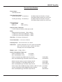
External Dimensions Page 6
Technical Specifications
Page 7
Power
Important Safety Instructions & Warranty Information Back Cover
28B-SST Amplifier
Introduction
Thank you for choosing the 28B-SST C-SERIES mono-block Power Amplifier.
Bryston welcomes any suggestions you may have, or comments regarding the operation of your amplifier. We consider
you, our customer, to be Bryston’s most important resource, and your opinion is very much appreciated.
Description 28B-SST
The 28B-SST is a single channel 1000 Watt audio power amplifier. The 28B-SST selects a balanced (3 pin XLR or ¼"
phone plug) or single ended (RCA/phono plug) input. A gain of 29dB or 23dB may be selected. The 28B-SST includes
‘soft start’ power control circuitry to eliminate high inrush currents when A/C power is applied. The power up or turn-on of
the 28B-SST may be activated by a remote control voltage 4v to 12v ac or dc.
Warranty ( see back page for details )
Shipping Box & Packing Material
Please keep the original shipping box and all packing material. This will ensure the amplifier is protected in future transport. In the unlikely event you have a problem and must return it for service you must use the proper packing material. Ship the
amplifier only in the original packing material, as the unit is not insurable by carriers otherwise.
Installation ( see rack mounting section if applicable )
Ventilation. The most important installation consideration is ventilation. The 28B-SST amplifier is convection cooled.
Unrestricted air-flow across the 28B-SST heat sinks is a must. For this reason do not install anything directly above it.
Allow 3.5’ (2u) to 5” (3u) inches of space above and to the sides of this amplifier. Do not install directly above other heat
generating equipment. Should your instillation conditions be constricted, then additional forced air-cooling may be necessary. Bryston can provide an optional fan package if required. Thermal shut down during operation indicates insufficient
air flow, and a remedy must be found for cooling the amplifier. Provide a minimum 6” space to the rear of the amplifier for
ventilation and dressing cables to and from the amplifier.
Never operate the amplifier in a vertical position.
Wiring the 28B-SST amplifier ( also see rear panel description )
Speaker wires should be as short as practical. Use quality wire, and if runs are more than 3 meters use at least 12 gage
wire. The speaker binding posts will accept wire up to 3 gage in size. Bryston offers speaker cables and amp interconnects
for your application. Check our website under products/cables (www.bryston.ca) for more information.
A/C power Before plugging in the power cord be sure your 28B-SST amplifier is specified for the correct ac voltage for your locality.
The voltage is listed on the label found at the upper right of the rear panel. The circuit feeding the 28B-SST should be sufficient so as not to cause the circuit breaker to trip (15 amp min.). Note: the 28B-SST when delivering maximum power into
a 4 ohm load, will consume all the available power in a normal household circuit, therefore a dedicated electrical circuit may
be necessary with this situation. Never lift the safety ground to the amplifier nor remove the ground pin from the plug.
1
28B-SST Amplifier
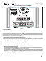
Rear Panel Input / Output Connections
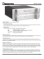
Figure 1
1. Input Select Switch.
The INPUT SELECT switch gives the user the option of switching between either balanced input or single ended input.
2. Input Sensitivity Selection.
This switch sets the gain of the amplifier to either 23dB or 29dB. The optimum gain setting will depend upon the source
pre-amp operating level, and or personal preference. Use the 23dB setting with any systems where the volume control
rotation is limited to the bottom half of the control or less.
3. Balanced Input connector. (input impedance 30KΩ each leg)
When 3-pin XLR jacks are used, pin 1 is ground, pin 2 is positive and pin 3 is negative. If your 28B-SST is equipped with
combination XLR/¼" phone jacks (as shown in the illustration above), the XLR jack will have the same pinout and on the
phone jack the TIP will be positive, RING is negative and the SLEEVE is ground..
Use quality, 100% shielded cables with gold plated connectors.
4. Single Ended Input. ( Un-balanced input) ( Imp. 50KΩ )
This input connector accepts standard ‘RCA’ or ‘Phono’ connectors.
Use quality, 100% shielded cables with gold plated connectors.
Balanced input Vs Single ended input:
The balanced input requires a balanced pre-amp source. Balanced systems provide noise rejection from external
electrical interference, so cable length can be very long ( 50m or longer ).
The single ended or unbalanced input is provided for pre-amps without balanced output. Single-ended cables should
be kept to 20’ (7m) or less. In general never use longer cables than necessary, never coil excess cable length, and
keep signal wires away from AC power or speaker cables.
5. Level Control. ("PRO" models only)
The level control will attenuate the input signal level from 0dB (fully clockwise) through -14dB (fully counter-clockwise).
2
28B-SST Amplifier
6. Output binding posts.
The RED binding posts are the in-phase amplifier output. Both red binding posts are the same. Connect either red binding
post to the (+) terminal on the loudspeaker. The second red binding post is provided for bi-wiring or second loudspeaker.
The BLUE binding posts are the inverted-phase amplifier output Connect either blue binding post to the (-) terminal on the
loudspeaker. The second blue binding post is provided for bi-wiring or second loudspeaker.
N.B.: At no time should either output be connected to a ground, or chassis. Failure of the
amplifier may result. Never connect either output in parallel with another amplifier.
N.B.: The minimum recommended loudspeaker load is 4 ohms.
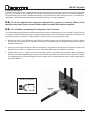
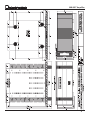
The Output binding posts provide three different interconnect options. Combinations may be used when bi-wiring. See figure 2 below. Cables should be kept as short as practical and should never be terminated with connectors that may become
confused for AC power connectors. Cables should be dressed away from input and power cables.
● Banana plugs offer a quick disconnect option. Before inserting a banana plug into the binding post be sure to tighten
the post nut to avoid rattling and to provide full insertion of the banana plug. Gold plated locking banana plugs are
available from Bryston.
● S
pade lugs provide high contact area and secure fastening. Lugs should be gold plated. See diagram for details. Post
diameter is 5/16’ ( 8mm ), lug width 5/8” (16 mm). Gold plated spade lugs are available from Bryston.
● Stripped bare wire up to 3 gage can be inserted through the hole in the binding post and held in place by tightening
the post knob. Additional tightening pressure can be achieved using a coin in the slots of the knob. Do not over tighten
or the binding post may become damaged. Note that copper wire is malleable and may require further tightening after
the initial installation.
Spade lug dimensions
SPADE
LUG
5/8”
5/16”
BARE
WIRE
BANANA
PLUG
3
28B-SST Amplifier
Power Control
(refer to figure 1 on page 2)
7. Master circuit - breaker.
The 28B-SST amplifier uses a magnetic-trip circuit breaker to protect the amplifier.
This switch should be ‘OFF’ during installation. When switched ‘OFF’
All A/C power is removed from the amplifier, including standby power.
The circuit breaker is not the power switch and should be switched to and left ‘ON’ after the installation is complete.
Use the 28B-sst front panel power switch or an external control voltage to Power-up or Power-down the amplifier.
Should the breaker trip, lower or remove the amplifier input signal (also see section 9 below). Switch the breaker to the
‘ON’ position. Then power the unit up normally.
The circuit breaker must be ‘ON’ at all times for the 28B-SST amplifier to operate.
8. AC power input.
On the rear panel is provided a high current plug for the power cord receptacle. Check that the voltage rating on the label (item 12 in figure 1, page 2) conforms with your locality. With the circuit breaker ‘OFF’ insert the power cord into the 28BSST amplifier, then plug the other end to an appropriate A/C power outlet. Switch the circuit breaker to on and observe
the LED labeled "Line Voltage Status Indicator".
9. LINE VOLTAGE STATUS INDICATOR
This LED will be on anytime the amplifier is plugged into a source of electrical power and the circuit breaker (#8) is ON. The amplifier cannot turn on unless the LED will is green.
Should the amplifier not power on, and the LED is flashing, remove the power cord from the rear of the amplifier and wait
a few seconds then plug the power cord back in.
Should the LED be red, a condition exists preventing the amplifier from powering up.
Reasons: the applied electrical power is outside the operating range, 120v unit connected to 230v, Check the electrical
ratings label on the rear panel to see if the voltage is correct for your location. Otherwise consult your dealer or call the
factory.
10 & 11: External control voltage power up ( Local/External switch & Interface Connector)
● To power-up the SST amplifier using an external control voltage:
1) The circuit breaker (#8) and front panel power switch (#13) must both be ON
2) Supply a 4v to 12v A/C or DC control voltage to the ‘IN’ terminals of connector ( #11 )
3) Use paired wire of 22 to 18 gage sufficient in length between the source device and the SST amplifier.
4) Set slide switch (item 11 in figure 1, page 2) to “External”. The amplifier will now power-up only when the control
voltage is present (on) and the front panel push-button power switch is ON (depressed). Immediately following
power up, the control voltage will appear at the ’OUT’ terminals of the interface connector (item 10 on figure 1,
page 2, also see below) for the control of other equipment. The removal of the control voltage (0v), or releasing
the front panel power switch, causes the amplifier to turn ‘off’ and the control voltage at the ‘OUT’ terminals is
interrupted.
● In the "Local” setting:
The 28B-SST amplifier will ignore the control voltage, and power up only by using the front panel ‘28BSST POWER’ switch, or as in section 3 above. If a control voltage is present at the ‘IN’ terminals it will still be available at the ‘OUT’ terminals after
the power-up sequence.
28BSST
Note:
The ‘OUT’ terminals are connected to the ‘IN’ terminals once the 28B-SST amplifier has powered-up. The control current is determined by the source equipment. The carrying current of
the ‘OUT’ relay is 2 amps. The 28B-SST control circuitry itself draws less than 2 mA from the
control current when operating.
4
28B-SST Amplifier
14
13
FRONT PANEL (refer to illustration above)
13. ‘28B-SST’ power switch
The front panel label ‘28B-sst’, is a push on push off switch used to apply or remove AC line power to the soft start
circuitry. ( Note: the rear circuit breaker must be on for the amplifier to power-up)
14. LED Indicators
The 28B-SST has an LED indicator to monitor the following conditions:
Unlit -
indicates the amplifier is turned off.
Red - indicates the amplifier is muted (as in a power-up sequence)
Green - indicates the amplifier operation is normal.
Flashing Red - indicates the amplifier clipping.
Orange -
indicates thermal shutdown.
Power up sequence
After pushing the '28B-SST POWER' switch, the LED will turn from unlit to red (mute). When the power supply has stabilized the amplifier will come out of mute and the LED will change to green (normal operation).
Unlit LED ( power off )
The 28B-SST LED when unlit indicates no A/C mains power is present and the amplifier probably needs only to be
powered on or the rear panel circuit breaker is switched off. Should the amplifier not power on when the power switch is
pushed see the installation instructions.
Clipping ( flashing red )
Clipping occurs when the channel output level no longer can follow the level increase at the input (Over driven input
condition). When the 28B-SST is driven into clipping the LED will change from green to red then back to green when
the level is reduced ( Flashing Red ). Momentary clipping can be tolerated, however it indicates that maximum undistorted power has been surpassed and potential speaker damage may result if overload conditions persist. Any amplifier
that is constantly operated into clipping indicates a more powerful amplifier is needed for that application.
Thermal Shutdown ( orange )
The 28B-SST has thermal shutdown circuitry to prevent damage due to overheating. Should thermal shutdown occur,
the amplifier will mute, and the LED will turn orange indicating this condition. When the amplifier has cooled to a safe
operating condition the 28B-SST will return to normal operation. Persistent Thermal shutdown indicates steps need to
be taken to increase airflow across the heat sink. ( Also see installation section on ventilation ).
5
28B-SST Amplifier
6
28B-SST Amplifier
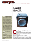
Technical Specifications
Power Output
1000 watts into 8Ω
Gain (Sensitivity) Select
"29 dB" gain setting = 1V sensitivity =
"23 dB" gain setting = 2V sensitivity =
Input Impedance
Single ended: 30KΩ
Balanced: 30KΩ each leg
100 Watts output into 8Ω with a 1V input
1000 Watts output into 8Ω with a 3.2V input
100 Watts output into 8Ω with a 2V input
1000 Watts output into 8Ω with a 6.4V input
Distortion IM or THD+noise < 0.007% 20Hz to20kHzat1000 wattsinto8Ω
Noise
Measured with input shorted - 20Hz to 20kHz.
>110dB below rated output 29dB gain (- 75dBu)
>113dB below rated output 23dB gain (- 78dBu)
Slew Rate > 60 volts per microsecond
Power Bandwidth < 1 Hz to over 100 kHz
Damping Factor Over 300 at 20 Hz, ref. 8 ohms
Dimensions: maximum dimensions for 19”w version with handles 48.3 x 20.5 x 52.1cm (19w” x 8.05”h x 20.525"d) See page 6 for more complete details
Weight: approx. 36.4kg - 80 lbs
Power Consumption & Heat Load
Power consumption at Idle ≈ 215 Watts
Max. heat dissipation at idle
≈ 733 Btu/Hr.
Power consumption @ 1000W output into 8 ohms Max. Heat dissipation @ 1000 Watts output into 8 ohms Maximum power output at onset of clipping into 8Ω
Power consumption at 1300 Watts output into 8Ω
Max. heat dissipation @ 1300 Watts output into 8Ω
≈ 1486 Watts
≈ 1658 Btu/Hr.
≈ 1300 Watts
≈ 2640 Watts
≈ 4572 BTU/Hr
Power output under normal operating conditons (1/8th max. pwr.) ≈ 161 Watts
Current consumption under normal operating conditons
≈ 9.3 Amps
Max. heat dissipation @ 1300 Watts output into 8Ω
≈ 955 BTU/Hr
7
IMPORTANT SAFETY INSTRUCTIONS
The lightning flash with arrowhead symbol within an equilateral triangle, is intended to alert the user to the presence of un-insulated
“dangerous voltage “ within the product’s enclosure that may be of sufficient magnitude to constitute a risk of electric shock to
persons.
The exclamation point within an equilateral triangle is intended to alert the user to the presence of important operating and maintenance
(servicing) instructions in the literature accompanying the product.
1. Read these instructions.
2. Keep these instructions.
3. Heed all warnings.
4. Follow all instructions.
5. Do not use this apparatus near water.
6. Clean only with dry cloth.
7.Do not block any ventilation openings. Install in accordance with the manufacturer’s instructions.
8.Do not install near any heat sources such as radiators, heat registers, stoves, or other apparatus (including amplifiers) that produce heat.
9.Do not defeat the safety purpose of the polarized or grounding-type plug. A polarized plug has two blades with one wider than the other. A
grounding type plug has two blades and a third grounding prong. The wide blade or the third prong are provided for your safety. If the provided plug does not fit into your outlet, consult an electrician for replacement of the obsolete outlet.
10.Protect the power cord from being walked on or pinched particularly at plugs, convenience receptacles, and the point where they exit from the
apparatus.
11. Only use attachments/accessories specified by the manufacturer.
12.Use only with the cart, stand, tripod, bracket, or table specified by the manufacturer, or sold with the apparatus. When a cart is
used use caution when moving the cart/apparatus combination to avoid injury from tip-over.
13.Unplug this apparatus during lightning storms or when unused for long periods of time.
14.Refer all servicing to qualified service personnel. Servicing is required when the apparatus has been damaged in any way, such as powersupply cord or plug is damaged, liquid has been spilled or objects have fallen into the apparatus, the apparatus has been exposed to rain or
moisture, does not operate normally, or has been dropped.
WARNING: TO REDUCE THE RISK OF FIRE OR ELECTRIC SHOCK, DO NOT EXPOSE THIS APPARATUS TO RAIN OR MOISTURE.
DO NOT EXPOSE THIS EQUIPMENT TO DRIPPING OR SPLASHING AND ENSURE THAT NO OBJECTS FILLED WITH LIQUIDS, SUCH AS VASES, ARE
PLACED ON THE EQUIPMENT.
TO COMPLETELY DISCONNECT THIS EQUIPMENT FROM THE AC MAINS, DISCONNECT THE POWER SUPPLY CORD PLUG FROM THE AC
RECEPTACLE.
THE MAINS PLUG OF THE POWER SUPPLY CORD SHALL REMAIN READILY OPERABLE.
BRYSTON LIMITED WARRANTY
Bryston analog audio circuits are warranted to be free from manufacturing defects for twenty (20) years from the original date of manufacture. The
warranty includes parts and labour.
Bryston Digital circuits and cables are warranted for five years from the original date of manufacture. The warranty includes parts and labour.
Bryston products having motorized moving parts, excluding motorized volume controls, are warranted for three years from the original date of manufacture. The warranty includes parts and labour.
Bryston will remedy the problem by repair or replacement, as we deem necessary, to restore the product to full performance. Bryston will pay shipping costs one way (usually the return portion) during the first three years of warranty coverage.
In the event of a defect or malfunction, contact Bryston’s repair centers for return authorization. Products must be returned using original packaging
material only. Packing material may be purchased from Bryston if necessary. This warranty is considered void if the defect, malfunction or failure of the
product or any component part was caused by damage (not resulting from a defect or malfunction) or abuse while in the possession of the customer.
Tampering by persons other than factory authorized service personnel or failure to fully comply with Bryston operating instructions voids the warranty.
This warranty gives you specific legal rights and you may also have other rights which may vary from province to province and country to country.
As of 2006-02-22 Bryston will only warranty Bryston products purchased through authorized Bryston dealers. Bryston products with a date code
of 0608 or higher (date code format is “yyww”, where “yy” is the two least significant digits of the year and “ww” is the week of the year) must be
accompanied by a copy of the bill-of-sale from a Bryston authorized dealer to qualify for warranty service. The warranty is transferable from the original
owner to a subsequent owner as long as a copy of the bill-of-sale from the original authorized Bryston dealer accompanies the re-sale. The copy of the
bill of sale to any subsequent owner need ONLY include the Name of the Bryston Authorized Dealer and the Model and Serial number of the Bryston
product The warranty will only be honored in the country of the original purchase unless otherwise pre-authorized by Bryston.
BRYSTON SERVICE in CANADA:
BRYSTON SERVICE in the USA:
BRYSTON SERVICE outside Canada and the USA:
Postal address: P.O. BOX 2170, Stn. Main
PETERBOROUGH, ONTARIO
CANADA K9J 7Y4
Courier address: 677 NEAL DRIVE
PETERBOROUGH, ONTARIO
CANADA K9J 6X7
79 COVENTRY ST., Suite 5
NEWPORT, VERMONT
U.S.A. 05855-2100
contact your local distributor or
PHONE:
FAX:
E-mail:
705-742-5325
705-742-0882
[email protected]
PHONE:
FAX: E-mail:
802-334-1201
802-334-6658
[email protected]
28Bsst_MANUAL_20061117
CHECK OUR WEB SITE: www.bryston.ca
E-MAIL BRYSTON DIRECTLY: [email protected]
FAX BRYSTON DIRECTLY: 01-705-742-0882
PHONE BRYSTON DIRECTLY: 01-705-742-5325