1
Cisco IOS Dial Technologies
Configuration Guide
Release 12.2
Corporate Headquarters
Cisco Systems, Inc.
170 West Tasman Drive
San Jose, CA 95134-1706
USA
http://www.cisco.com
Tel: 408 526-4000
800 553-NETS (6387)
Fax: 408 526-4100
Customer Order Number: DOC-7812090=
Text Part Number: 78-12090-02
THE SPECIFICATIONS AND INFORMATION REGARDING THE PRODUCTS IN THIS MANUAL ARE SUBJECT TO CHANGE WITHOUT
NOTICE. ALL STATEMENTS, INFORMATION, AND RECOMMENDATIONS IN THIS MANUAL ARE BELIEVED TO BE ACCURATE BUT ARE
PRESENTED WITHOUT WARRANTY OF ANY KIND, EXPRESS OR IMPLIED. USERS MUST TAKE FULL RESPONSIBILITY FOR THEIR
APPLICATION OF ANY PRODUCTS.
THE SOFTWARE LICENSE AND LIMITED WARRANTY FOR THE ACCOMPANYING PRODUCT ARE SET FORTH IN THE INFORMATION
PACKET THAT SHIPPED WITH THE PRODUCT AND ARE INCORPORATED HEREIN BY THIS REFERENCE. IF YOU ARE UNABLE TO
LOCATE THE SOFTWARE LICENSE OR LIMITED WARRANTY, CONTACT YOUR CISCO REPRESENTATIVE FOR A COPY.
The Cisco implementation of TCP header compression is an adaptation of a program developed by the University of California, Berkeley (UCB) as part of
UCB’s public domain version of the UNIX operating system. All rights reserved. Copyright © 1981, Regents of the University of California.
NOTWITHSTANDING ANY OTHER WARRANTY HEREIN, ALL DOCUMENT FILES AND SOFTWARE OF THESE SUPPLIERS ARE PROVIDED
“AS IS” WITH ALL FAULTS. CISCO AND THE ABOVE-NAMED SUPPLIERS DISCLAIM ALL WARRANTIES, EXPRESSED OR IMPLIED,
INCLUDING, WITHOUT LIMITATION, THOSE OF MERCHANTABILITY, FITNESS FOR A PARTICULAR PURPOSE AND
NONINFRINGEMENT OR ARISING FROM A COURSE OF DEALING, USAGE, OR TRADE PRACTICE.
IN NO EVENT SHALL CISCO OR ITS SUPPLIERS BE LIABLE FOR ANY INDIRECT, SPECIAL, CONSEQUENTIAL, OR INCIDENTAL
DAMAGES, INCLUDING, WITHOUT LIMITATION, LOST PROFITS OR LOSS OR DAMAGE TO DATA ARISING OUT OF THE USE OR
INABILITY TO USE THIS MANUAL, EVEN IF CISCO OR ITS SUPPLIERS HAVE BEEN ADVISED OF THE POSSIBILITY OF SUCH DAMAGES.
CCIP, CCSP, the Cisco Arrow logo, the Cisco Powered Network mark, Cisco Unity, Follow Me Browsing, FormShare, and StackWise are trademarks of
Cisco Systems, Inc.; Changing the Way We Work, Live, Play, and Learn, and iQuick Study are service marks of Cisco Systems, Inc.; and Aironet, ASIST,
BPX, Catalyst, CCDA, CCDP, CCIE, CCNA, CCNP, Cisco, the Cisco Certified Internetwork Expert logo, Cisco IOS, the Cisco IOS logo, Cisco Press,
Cisco Systems, Cisco Systems Capital, the Cisco Systems logo, Empowering the Internet Generation, Enterprise/Solver, EtherChannel, EtherSwitch, Fast
Step, GigaStack, Internet Quotient, IOS, IP/TV, iQ Expertise, the iQ logo, iQ Net Readiness Scorecard, LightStream, MGX, MICA, the Networkers logo,
Networking Academy, Network Registrar, Packet, PIX, Post-Routing, Pre-Routing, RateMUX, Registrar, ScriptShare, SlideCast, SMARTnet, StrataView
Plus, Stratm, SwitchProbe, TeleRouter, The Fastest Way to Increase Your Internet Quotient, TransPath, and VCO are registered trademarks of Cisco
Systems, Inc. and/or its affiliates in the U.S. and certain other countries.
All other trademarks mentioned in this document or Web site are the property of their respective owners. The use of the word partner does not imply a
partnership relationship between Cisco and any other company. (0304R)
Cisco IOS Dial Technologies Configuration Guide
Copyright © 2002–2006, Cisco Systems, Inc.
All rights reserved.
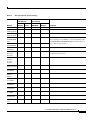
C O N T E N T S
About Cisco IOS Software Documentation
Documentation Objectives
Audience
xxxvii
xxxvii
xxxvii
Documentation Organization xxxvii
Documentation Modules xxxvii
Master Indexes xl
Supporting Documents and Resources
New and Changed Information
Document Conventions
xl
xli
xli
Obtaining Documentation xlii
World Wide Web xlii
Documentation CD-ROM xliii
Ordering Documentation xliii
Documentation Feedback
xliii
Obtaining Technical Assistance xliii
Cisco.com xliv
Technical Assistance Center xliv
Contacting TAC by Using the Cisco TAC Website
Contacting TAC by Telephone xliv
Using Cisco IOS Software
xliv
xlvii
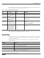
Understanding Command Modes
xlvii
Getting Help xlviii
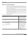
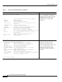
Example: How to Find Command Options
xlix
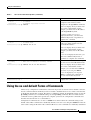
Using the no and default Forms of Commands
li
Saving Configuration Changes
lii
Filtering Output from the show and more Commands
lii
Identifying Supported Platforms liii
Using Feature Navigator liii
Using Software Release Notes liii
iii
Contents
DIAL INTERFACES, CONTROLLERS, AND LINES
Overview of Dial Interfaces, Controllers, and Lines
Cisco IOS Dial Components
DC-2
DC-2
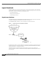
Logical Constructs DC-4
Asynchronous Interfaces DC-4
Group Asynchronous Interfaces DC-5
Virtual Template Interfaces DC-5
Templates for Virtual Access Interfaces DC-6
Templates for Protocol Translation DC-6
Logical Interfaces DC-6
Dialer Interfaces DC-7
Virtual Access Interfaces DC-8
Virtual Asynchronous Interfaces DC-9
Circuit-Switched Digital Calls
T1 and E1 Controllers
DC-9
DC-10
Non-ISDN Channelized T1 and Channelized E1 Lines
DC-10
ISDN Service DC-11
ISDN BRI DC-12
ISDN PRI DC-12
Line Types DC-14
Relationship Between Lines and Interfaces DC-15
Asynchronous Interfaces and Physical Terminal Lines DC-15
Synchronous Interfaces and Virtual Terminal Lines DC-16
Encapsulation Types
DC-17
Configuring Asynchronous Lines and Interfaces
DC-18
How to Configure Asynchronous Interfaces and Lines DC-18
Configuring a Typical Asynchronous Interface DC-19
Monitoring and Maintaining Asynchronous Connections DC-19
Creating a Group Asynchronous Interface DC-20
Verifying the Group Interface Configuration DC-21
Configuring Asynchronous Rotary Line Queueing DC-24
Verifying Asynchronous Rotary Line Queueing DC-25
Troubleshooting Asynchronous Rotary Lines DC-25
Monitoring and Maintaining Asynchronous Rotary Line Queues DC-26
Configuring Autoselect DC-26
Verifying Autoselect PPP DC-27
Verifying Autoselect ARA DC-27
iv
Contents
How to Configure Other Asynchronous Line and Interface Features DC-28
Configuring the Auxiliary (AUX) Port DC-28
Establishing and Controlling the EXEC Process DC-29
Enabling Routing on Asynchronous Interfaces DC-30
Configuring Dedicated or Interactive PPP and SLIP Sessions DC-30
Conserving Network Addresses DC-31
Using Advanced Addressing Methods for Remote Devices DC-32
Assigning a Default Asynchronous Address DC-32
Allowing an Asynchronous Address to Be Assigned Dynamically DC-32
Optimizing Available Bandwidth DC-33
Configuring Header Compression DC-33
Forcing Header Compression at the EXEC Level DC-34
Configuration Examples for Asynchronous Interfaces and Lines DC-34
Interface and Line Configuration Examples DC-35
Asynchronous Interface Backup DDR Configuration Example DC-35
Passive Header Compression and Default Address Example DC-35
High-Density Dial-In Solution Using Autoselect and EXEC Control Example DC-35
Asynchronous Line Backup DDR Configuration Example DC-36
Line AUX Configuration Example DC-36
Rotary Group Examples DC-36
Dedicated Asynchronous Interface Configuration Example DC-37
Access Restriction on the Asynchronous Interface Example DC-37
Group and Member Asynchronous Interface Examples DC-37
Asynchronous Group Interface Examples DC-38
Modem Asynchronous Group Example DC-38
High-Density Dial-In Solution Using an Asynchronous Group DC-39
Asynchronous Interface Address Pool Examples DC-39
DHCP Pooling Example DC-39
Local Pooling Example DC-39
Configuring Specific IP Addresses for an Interface DC-40
IP and SLIP Using an Asynchronous Interface Example DC-40
IP and PPP Asynchronous Interface Configuration Example DC-40
Asynchronous Routing and Dynamic Addressing Configuration Example DC-41
TCP Header Compression Configuration Example DC-41
Network Address Conservation Using the ip unnumbered Command Example DC-41
Asynchronous Interface As the Only Network Interface Example DC-42
Routing on a Dedicated Dial-In Router Example DC-42
IGRP Configuration Example DC-43
v
Contents
Configuring Asynchronous Serial Traffic
over UDP DC-44
UDPTN Overview
DC-44
How to Configure Asynchronous Serial Traffic over UDP DC-45
Preparing to Configure Asynchronous Serial Traffic over UDP
Configuring a Line for UDPTN DC-45
Enabling UDPTN DC-46
Verifying UDPTN Traffic DC-46
Configuration Examples for UDPTN DC-47
Multicast UDPTN Example DC-47
Broadcast UDPTN Example DC-48
Point-to-Point UDPTN Example DC-48
MODEM CONFIGURATION AND MANAGEMENT
Overview of Modem Interfaces
DC-52
Cisco Modems and Cisco IOS Modem Features
Cisco IOS Modem Components
DC-52
DC-53
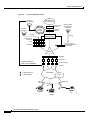
Logical Constructs in Modem Configurations DC-55
Asynchronous Interfaces DC-55
Group Asynchronous Interfaces DC-56
Modem Lines and Asynchronous Interfaces DC-57
Modem Calls DC-58
Asynchronous Line Configuration DC-58
Absolute Versus Relative Line Numbers DC-58
Line and Modem Numbering Issues DC-59
Decimal TCP Port Numbers for Line Connections DC-60
Signal and Flow Control Overview DC-61
Configuring and Managing Integrated Modems
DC-62
Modems and Modem Feature Support DC-62
V.90 Modem Standard DC-63
V.110 Bit Rate Adaption Standard DC-63
V.120 Bit Rate Adaptation Standard DC-65
Managing Modems DC-65
Managing SPE Firmware DC-66
Configuring Modems in Cisco Access Servers DC-68
Configuring Modem Lines DC-68
Verifying the Dial-In Connection DC-69
Troubleshooting the Dial-In Connection DC-70
vi
DC-45
Contents
Configuring the Modem Using a Modemcap DC-70
Configuring the Modem Circuit Interface DC-72
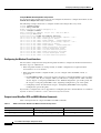
Comparison of NextPort SPE and MICA Modem Commands DC-72
Configuring Cisco Integrated Modems Using Modem Attention Commands DC-75
Using Modem Dial Modifiers on Cisco MICA Modems DC-75
Changing Configurations Manually in Integrated Microcom Modems DC-76
Configuring Leased-Line Support for Analog Modems DC-77
Configuring Modem Pooling DC-81
Creating a Modem Pool DC-82
Verifying Modem Pool Configuration DC-83
Configuring Physical Partitioning DC-84
Creating a Physical Partition DC-85
Physical Partitioning with Dial-In and Dial-Out Scenario DC-87
Configuring Virtual Partitioning DC-89
Configuring Call Tracker DC-90
Verifying Call Tracker DC-91
Enabling Call Tracker DC-91
Configuring Polling of Link Statistics on MICA Modems DC-92
Configuring MICA In-Band Framing Mode Control Messages DC-93
Enabling Modem Polling DC-94
Setting Modem Poll Intervals DC-94
Setting Modem Poll Retry DC-94
Collecting Modem Statistics DC-94
Logging EIA/TIA Events DC-94
Configuring a Microcom Modem to Poll for Statistics DC-95
Troubleshooting Using a Back-to-Back Modem Test Procedure DC-95
Clearing a Direct Connect Session on a Microcom Modem DC-98
Displaying Local Disconnect Reasons DC-98
Removing Inoperable Modems DC-101
Busying Out a Modem Card DC-103
Monitoring Resources on Cisco High-End Access Servers DC-103
Enabling DS0 Busyout Traps DC-104
Enabling ISDN PRI Requested Channel Not Available Traps DC-105
Enabling Modem Health Traps DC-105
Enabling DS1 Loopback Traps DC-105
Verifying Enabled Traps DC-105
Troubleshooting the Traps DC-106
NAS Health Monitoring Example DC-106
Configuration Examples for Modem Management
NextPort Modem Log Example DC-109
DC-109
vii
Contents
Modem Performance Summary Example DC-110
Modem AT-Mode Example DC-110
Connection Speed Performance Verification Example
DC-110
Configuring and Managing Cisco Access Servers and Dial Shelves
Cisco AS5800 Dial Shelf Architecture and DSIP Overview
Split Dial Shelves Feature DC-114
DC-113
DC-113
How to Configure Dial Shelves DC-114
Configuring the Shelf ID DC-115
Configuring Redundant DSC Cards DC-116
Synchronizing to the System Clocks DC-117
Verifying External Clock Configuration DC-118
Configuring Dial Shelf Split Mode DC-118
Changing Slot Sets DC-120
Leaving Split Mode DC-121
Troubleshooting Split Dial Shelves DC-121
Managing a Split Dial Shelf DC-121
Executing Commands Remotely DC-122
Verifying DSC Configuration DC-123
Monitoring and Maintaining the DSCs DC-123
Troubleshooting DSIP DC-123
Port Management Services on Cisco Access Servers
DC-124
Upgrading and Configuring SPE Firmware DC-126
Downloading SPE Firmware from the Cisco.com FTP Server to a Local TFTP Server
Copying the SPE Firmware File from the Local TFTP Server to the SPEs DC-129
Specifying a Country Name DC-130
Configuring Dial Split Shelves (AS5800 Only) DC-130
Configuring SPEs to Use an Upgraded Firmware File DC-131
Disabling SPEs DC-132
Rebooting SPEs DC-133
Configuring Lines DC-134
Configuring Ports DC-135
Verifying SPE Line and Port Configuration DC-136
Configuring SPE Performance Statistics DC-136
Clearing Log Events DC-137
Troubleshooting SPEs DC-137
Monitoring SPE Performance Statistics DC-139
SPE Events and Firmware Statistics DC-139
Port Statistics DC-139
Digital SPE Statistics DC-140
viii
DC-127
Contents
SPE Modem Statistics
DC-141
Configuring and Managing External Modems
DC-143
External Modems on Low-End Access Servers
DC-143
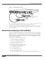
Automatically Configuring an External Modem
DC-144
Manually Configuring an External Modem
Supporting Dial-In Modems
DC-147
Testing the Modem Connection
Managing Telnet Sessions
DC-146
DC-149
DC-150
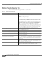
Modem Troubleshooting Tips
DC-152
Checking Other Modem Settings
Modem Signal and Line States
DC-153
DC-154
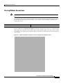
Signal and Line State Diagrams DC-154
Configuring Automatic Dialing DC-156
Automatically Answering a Modem DC-156
Supporting Dial-In and Dial-Out Connections DC-157
Configuring a Line Timeout Interval DC-158
Closing Modem Connections DC-159
Configuring a Line to Disconnect Automatically DC-160
Supporting Reverse Modem Connections and Preventing Incoming Calls
Creating and Using Modem Chat Scripts
Chat Script Overview
DC-160
DC-162
DC-162
How To Configure Chat Scripts DC-163
Understanding Chat Script Naming Conventions DC-163
Creating a Chat Script DC-163
Chat String Escape Key Sequences DC-164
Adding a Return Key Sequence DC-164
Chat String Special-Case Script Modifiers DC-165
Configuring the Line to Activate Chat Scripts DC-165
Manually Testing a Chat Script on an Asynchronous Line DC-166
Using Chat Scripts DC-166
Generic Chat Script Example DC-166
Traffic-Handling Chat Script Example DC-166
Modem-Specific Chat Script Examples DC-167
Dialer Mapping Example DC-167
System Login Scripts and Modem Script Examples
DC-168
ix
Contents
ISDN CONFIGURATION
Configuring ISDN BRI
DC-172
ISDN Overview DC-172
Requesting BRI Line and Switch Configuration from a Telco Service Provider
Interface Configuration DC-175
Dynamic Multiple Encapsulations DC-175
Interface Configuration Options DC-175
ISDN Cause Codes DC-176
How to Configure ISDN BRI DC-177
Configuring the ISDN BRI Switch DC-177
Configuring the Switch Type DC-177
Checking and Setting the Buffers DC-178
Multiple ISDN Switch Types Feature DC-179
Specifying Interface Characteristics for an ISDN BRI DC-179
Specifying the Interface and Its IP Address DC-180
Specifying ISDN SPIDs DC-180
Configuring Encapsulation on ISDN BRI DC-180
Configuring Network Addressing DC-182
Configuring TEI Negotiation Timing DC-183
Configuring CLI Screening DC-183
Configuring Called Party Number Verification DC-183
Configuring ISDN Calling Number Identification DC-184
Configuring the Line Speed for Calls Not ISDN End to End DC-184
Configuring a Fast Rollover Delay DC-185
Overriding ISDN Application Default Cause Codes DC-185
Configuring Inclusion of the Sending Complete Information Element
Configuring DNIS-plus-ISDN-Subaddress Binding DC-186
Screening Incoming V.110 Modem Calls DC-186
Disabling V.110 Padding DC-187
Configuring ISDN Semipermanent Connections DC-187
Configuring ISDN BRI for Leased-Line Service DC-187
Configuring Leased-Line Service at Normal Speeds DC-188
Configuring Leased-Line Service at 128 Kbps DC-188
Monitoring and Maintaining ISDN Interfaces
Troubleshooting ISDN Interfaces
DC-189
DC-189
Configuration Examples for ISDN BRI DC-190
Global ISDN and BRI Interface Switch Type Example
BRI Connected to a PBX Example DC-190
x
DC-190
DC-173
DC-186
Contents
Multilink PPP on a BRI Interface Example DC-190
Dialer Rotary Groups Example DC-191
Compression Examples DC-191
Multilink PPP and Compression Example DC-192
Voice over ISDN Examples DC-192
DNIS-plus-ISDN-Subaddress Binding Example DC-193
Screening Incoming V.110 Modem Calls Example DC-193
ISDN BRI Leased-Line Configuration Example DC-193
Configuring Virtual Asynchronous Traffic
over ISDN DC-194
Recommendation V.120 Overview
DC-195
How to Configure V.120 Access DC-195
Configuring Answering of All Incoming Calls as V.120 DC-195
Configuring Automatic Detection of Encapsulation Type DC-196
Enabling V.120 Support for Asynchronous Access over ISDN DC-196
Configuration Example for V.120
ISDN LAPB-TA Overview
DC-197
DC-197
How to Configure ISDN LAPB-TA DC-198
Verifying ISDN LAPB-TA DC-199
Configuration Example for ISDN LAPB-TA
Configuring Modem Use over ISDN BRI
Modem over ISDN BRI Overview
DC-200
DC-201
DC-202
How to Configure Modem over ISDN BRI DC-203
Verifying ISDN BRI Interface Configuration DC-206
Configuration Examples for Modem over ISDN BRI
BRI Interface Configuration Example DC-208
Complete Configuration Examples DC-211
Configuring X.25 on ISDN
DC-208
DC-222
X.25 on ISDN Overview DC-222
X.25-over-D-Channel Logical Interface DC-222
Outbound Circuit-Switched X.25 Support over a Dialer Interface
How to Configure X.25 on ISDN DC-223
Configuring X.25 on the ISDN D Channel
DC-223
DC-224
Configuration Examples for X.25 on ISDN DC-224
X.25 on ISDN D-Channel Configuration Example DC-224
Outbound Circuit-Switched X.25 Example DC-225
xi
Contents
Configuring X.25 on ISDN Using AO/DI
DC-230
AO/DI Overview DC-230
PPP over X.25 Encapsulation DC-232
Multilink PPP Bundle DC-233
MLP Encapsulation Enhancements DC-233
BACP/BAP DC-234
How to Configure an AO/DI Interface DC-234
Configuring PPP and BAP on the Client DC-234
Configuring X.25 Parameters on the Client DC-235
Configuring PPP and BAP on the Server DC-235
Configuring X.25 Parameters on the Server DC-236
How to Configure an AO/DI Client/Server DC-236
Configuring the AO/DI Client DC-237
Enabling AO/DI on the Interface DC-237
Enabling the AO/DI Interface to Initiate Client Calls DC-237
Enabling the MLP Bundle to Add Multiple Links DC-237
Modifying BACP Default Settings DC-238
Configuring the AO/DI Server DC-238
Enabling the Interface to Receive AO/DI Client Calls DC-238
Enabling the MLP Bundle to Add Multiple Links DC-239
Modifying BACP Default Settings DC-239
Configuration Examples for AO/DI DC-240
AO/DI Client Configuration Example DC-240
AO/DI Server Configuration Example DC-241
Configuring ISDN on Cisco 800 Series Routers
DC-242
CAPI and RCAPI Overview DC-243
Framing Protocols DC-243
Data Link and Network Layer Protocols DC-243
CAPI Features DC-243
Supported B-Channel Protocols DC-244
Supported Switch Types DC-245
CAPI and RVS-COM DC-245
Supported Applications DC-246
Helpful Website DC-246
How to Configure RCAPI DC-246
Configuring RCAPI on the Cisco 800 Series Router
Monitoring and Maintaining RCAPI DC-247
Troubleshooting RCAPI DC-247
xii
DC-246
Contents
Configuration Examples for RCAPI
DC-247
SIGNALING CONFIGURATION
Configuring ISDN PRI
DC-252
Signaling Overview DC-253
In-Band and Out-of-Band Signaling DC-253
Channelized E1 and T1 on Cisco Devices DC-253
How to Configure ISDN PRI DC-254
Requesting PRI Line and Switch Configuration from a Telco Service Provider DC-254
Configuring Channelized E1 ISDN PRI DC-255
Configuring Channelized T1 ISDN PRI DC-256
Configuring the Serial Interface DC-257
Specifying an IP Address for the Interface DC-258
Configuring Encapsulation on ISDN PRI DC-258
Configuring Network Addressing DC-260
Configuring ISDN Calling Number Identification DC-261
Overriding the Default TEI Value DC-261
Configuring a Static TEI DC-261
Configuring Incoming ISDN Modem Calls DC-261
Filtering Incoming ISDN Calls DC-262
Configuring the ISDN Guard Timer DC-263
Configuring Inclusion of the Sending Complete Information Element DC-263
Configuring ISDN PRI B-Channel Busyout DC-264
Configuring NSF Call-by-Call Support DC-264
Configuring Multiple ISDN Switch Types DC-265
Configuring B Channel Outgoing Call Order DC-267
Performing Configuration Self-Tests DC-267
Monitoring and Maintaining ISDN PRI Interfaces
DC-268
How to Configure Robbed-Bit Signaling for Analog Calls over T1 Lines
DC-268
How to Configure CAS DC-270
CAS on Channelized E1 DC-270
Configuring CAS for Analog Calls over E1 Lines DC-271
Configuring CAS on a Cisco Router Connected to a PBX or PSTN
CAS on T1 Voice Channels DC-272
Configuring ANI/DNIS Delimiters for CAS Calls on CT1 DC-272
DC-271
How to Configure Switched 56K Digital Dial-In over Channelized T1 and Robbed-Bit Signaling
Switched 56K Scenarios DC-274
Switched 56K and Analog Modem Calls into T1 CAS DC-274
DC-273
xiii
Contents
Basic Call Processing Components DC-275
ISDN BRI Calls into T1 CAS DC-276
How to Configure Switched 56K Services
DC-276
How to Configure E1 R2 Signaling DC-277
E1 R2 Signaling Overview DC-277
Configuring E1 R2 Signaling DC-280
Configuring E1 R2 Signaling for Voice DC-280
Monitoring E1 R2 Signaling DC-281
Verifying E1 R2 Signaling DC-282
Troubleshooting E1 R2 Signaling DC-283
Enabling R1 Modified Signaling in Taiwan DC-284
R1 Modified Signaling Topology DC-284
R1 Modified Signaling Configuration Task List DC-285
Configuring R1 Modified Signaling on a T1 Interface DC-286
Configuring R1 Modified Signaling on an E1 Interface DC-287
Troubleshooting Channelized E1 and T1 Channel Groups DC-288
Interface Local Loopback DC-288
Interface Remote Loopback DC-289
Configuration Examples for Channelized E1 and Channelized T1 DC-289
ISDN PRI Examples DC-289
Global ISDN, BRI, and PRI Switch Example DC-290
Global ISDN and Multiple BRI and PRI Switch Using TEI Negotiation Example DC-290
NSF Call-by-Call Support Example DC-290
PRI on a Cisco AS5000 Series Access Server Example DC-291
ISDN B-Channel Busyout Example DC-293
Multiple ISDN Switch Types Example DC-293
Outgoing B-Channel Ascending Call Order Example DC-293
Static TEI Configuration Example DC-294
Call Reject Configuration Examples DC-294
ISDN Cause Code Override and Guard Timer Example DC-294
PRI Groups and Channel Groups on the Same Channelized T1 Controller Example DC-294
Robbed-Bit Signaling Examples DC-295
Allocating All Channels for Robbed-Bit Signaling Example DC-295
Mixing and Matching Channels—Robbed-Bit Signaling and Channel Grouping DC-295
Switched 56K Configuration Examples DC-295
Switched 56K T1 Controller Procedure DC-296
Mixture of Switched 56K and Modem Calls over CT1 CAS Example DC-296
Switched 56K and Analog Modem Calls over Separate T1 CAS Lines Example DC-297
Comprehensive Switched 56K Startup Configuration Example DC-297
xiv
Contents
ISDN CAS Examples DC-302
Allocating All Channels for CAS Example DC-302
Mixing and Matching Channels—CAS and Channel Grouping Example
E1 R2 Signaling Procedure DC-303
R1 Modified Signaling Using an E1 Interface Example DC-306
R1 Modified Signaling for Taiwan Configuration Example DC-307
Configuring ISDN Special Signaling
DC-303
DC-308
How to Configure ISDN Special Signaling DC-308
Configuring ISDN AOC DC-309
Configuring Short-Hold Mode DC-309
Monitoring ISDN AOC Call Information DC-310
Configuring NFAS on PRI Groups DC-310
ISDN NFAS Prerequisites DC-311
ISDN NFAS Configuration Task List DC-311
Configuring NFAS on PRI Groups DC-311
Configuring NTT PRI NFAS DC-312
Disabling a Channel or Interface DC-313
When the T1 Controller Is Shut Down DC-314
Monitoring NFAS Groups DC-314
Monitoring ISDN Service DC-314
Enabling an ISDN PRI to Take PIAFS Calls on MICA Modems DC-314
Verifying PIAFS DC-315
Configuring Automatic Detection of Encapsulation Type DC-315
Configuring Encapsulation for Combinet Compatibility DC-316
Troubleshooting ISDN Special Signaling
DC-317
Configuration Examples for ISDN Special Signaling DC-317
ISDN AOC Configuration Examples DC-317
Using Legacy DDR for ISDN PRI AOC Configuration DC-317
Using Dialer Profiles for ISDN BRI AOC Configuration DC-318
ISDN NFAS Configuration Examples DC-319
NFAS Primary and Backup D Channels DC-319
PRI Interface Service State DC-320
NTT PRI NFAS Primary D Channel Example DC-320
Configuring Network Side ISDN PRI Signaling, Trunking, and Switching
DC-322
Network Side ISDN PRI Signaling Overview DC-322
Call Switching Using Dial Peers DC-323
Trunk Group Resource Manager DC-323
Class of Restrictions DC-324
xv
Contents
ISDN Disconnect Timers
DC-324
How to Configure Network Side ISDN PRI DC-324
Configuring ISDN Network Side DC-325
Configuring ISDN Network Side for the National ISDN Switch Type DC-326
Configuring ISDN Network Side for ETSI Net5 PRI DC-326
Configuring Global or Interface Trunk Groups DC-327
Configuring Classes of Restrictions DC-328
Configuring ISDN T306 and T310 Timers DC-329
Verifying Network Side ISDN PRI Signaling, Trunking, and Switching DC-329
Monitoring Network Side ISDN PRI DC-332
Monitoring TGRM DC-333
Configuration Examples for Network Side ISDN PRI Signaling, Trunking, and Switching
Call Switching and Dial Peers Configuration on T1/T3 Example DC-333
Trunk Group Configuration Example DC-334
COR for Dial Peer Configuration Example DC-334
COR Based on Outgoing Dial Peers Example DC-335
Dial Peers and Trunk Groups for Special Numbers Examples DC-336
ISDN Network Side for ETSI Net5 PRI Configuration on E1 Example DC-337
T306/T310 Timer Configuration Example DC-337
DIAL-ON-DEMAND ROUTING CONFIGURATION
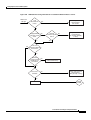
Preparing to Configure DDR
DC-340
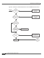
DDR Decision Flowchart
DC-340
DDR Topology Decisions
DC-342
DDR-Independent Implementation Decisions
DDR-Dependent Implementation Decisions
Dialer Profiles DC-343
Legacy DDR DC-344
Simple or Complex DDR Configuration
DC-342
DC-343
DC-344
Global and Interface Preparations for DDR DC-344
Preparations Depending on the Selected Interface Type
DC-345
Preparations for Routing or Bridging over DDR DC-345
Preparing for Transparent Bridging over DDR DC-345
Defining the Protocols to Bridge DC-345
Specifying the Bridging Protocol DC-346
Controlling Bridging Access DC-346
Preparing for Routing over DDR DC-346
Configuring the Protocol for Routing and Access Control
xvi
DC-347
DC-333
Contents
Associating the Protocol Access List with a Dialer Group
DC-351
Configuration Examples for Legacy DDR DC-351
Point-to-Point DDR Without Authentication Examples DC-351
Point-to-Point DDR with Authentication Examples DC-353
Configuring Legacy DDR Spokes
DC-355
DDR Spokes Configuration Task Flow
DC-355
How to Configure DDR DC-356
Specifying the Interface DC-357
Enabling DDR on the Interface DC-358
Configuring the Interface to Place Calls DC-359
Specifying the Dial String for Synchronous Serial Interfaces DC-359
Specifying Chat Scripts and Dial Strings for Asynchronous Serial Interfaces DC-359
Configuring the Interface to Receive Calls DC-359
Configuring the Interface to Place and Receive Calls DC-360
Defining the Traffic to Be Authenticated DC-360
Configuring Access Control for Outgoing Calls DC-361
Configuring Access Control for Bridging DC-361
Controlling Bridging Access by Ethernet Type Codes DC-362
Permitting All Bridge Packets to Trigger Calls DC-362
Assigning the Interface to a Bridge Group DC-362
Configuring Access Control for Routing DC-362
Customizing the Interface Settings DC-363
Configuring Timers on the DDR Interface DC-363
Setting Dialer Interface Priority DC-364
Configuring a Dialer Hold Queue DC-365
Configuring Bandwidth on Demand DC-365
Disabling and Reenabling DDR Fast Switching DC-366
Configuring Dialer Redial Options DC-366
Sending Traffic over Frame Relay, X.25, or LAPB Networks DC-366
Configuring the Interface for Sending Traffic over a Frame Relay Network DC-367
Configuring the Interface for Sending Traffic over an X.25 Network DC-368
Configuring the Interface for Sending Traffic over a LAPB Network DC-369
Monitoring DDR Connections
DC-369
Configuration Examples for Legacy DDR Spoke DC-370
Legacy Dial-on-Demand Routing Example DC-370
Transparent Bridging over DDR Examples DC-371
DDR Configuration in an IP Environment Example DC-372
Two-Way DDR for Novell IPX Example DC-372
Remote Configuration Example DC-372
xvii
Contents
Local Configuration Example DC-373
AppleTalk Configuration Example DC-374
DECnet Configuration Example DC-374
ISO CLNS Configuration Example DC-375
XNS Configuration Example DC-375
Single Site Dialing Example DC-375
DTR Dialing Example DC-376
Hub-and-Spoke DDR for Asynchronous Interfaces and Authentication Example DC-377
Spoke Topology Configuration DC-377
Hub Router Configuration DC-378
Two-Way Reciprocal Client/Server DDR Without Authentication Example DC-379
Remote Configuration DC-379
Local Configuration DC-379
Frame Relay Support Example DC-380
Frame Relay Access with In-Band Dialing (V.25bis) and Static Mapping Example DC-380
Frame Relay Access with ISDN Dialing and DDR Dynamic Maps Example DC-381
X.25 Support Example DC-381
LAPB Support Example DC-382
Configuring Legacy DDR Hubs
DDR Issues
DC-383
DC-383
DDR Hubs Configuration Task Flow
DC-384
How to Configure DDR DC-385
Specifying the Interface DC-385
Enabling DDR on the Interface DC-386
Configuring the Interface to Place Calls Only DC-386
Defining the Dialing Destination DC-387
Specifying a Physical Interface to Use and Assigning It to a Dialer Rotary Group DC-387
Configuring the Interface to Receive Calls Only DC-388
Configuring the Interface for TACACS+ DC-389
Configuring the Interface for PPP Authentication DC-389
Specifying Physical Interfaces and Assigning Them to the Dialer Rotary Group DC-390
Configuring the Interface to Place and Receive Calls DC-390
Defining One or More Dialing Destinations DC-391
Defining the Traffic to Be Authenticated DC-392
Configuring Access Control for Outgoing Calls DC-392
Configuring Access Control for Bridging DC-392
Configuring Access Control for Routing DC-393
Customizing the Interface Settings DC-393
Configuring Timers on the DDR Interface DC-393
xviii
Contents
Setting Dialer Interface Priority DC-395
Configuring a Dialer Hold Queue DC-395
Configuring Bandwidth on Demand DC-395
Disabling and Reenabling DDR Fast Switching DC-396
Configuring Dialer Redial Options DC-396
Sending Traffic over Frame Relay, X.25, or LAPB Networks DC-397
Configuring the Interface for Sending Traffic over a Frame Relay Network DC-397
Configuring the Interface for Sending Traffic over an X.25 Network DC-399
Configuring the Interface for Sending Traffic over a LAPB Network DC-399
Monitoring DDR Connections
DC-400
Configuration Examples for Legacy DDR Hub DC-400
Transparent Bridging over DDR Examples DC-401
DDR Configuration in an IP Environment Example DC-402
AppleTalk Configuration Example DC-402
Banyan VINES Configuration Example DC-403
DECnet Configuration Example DC-403
ISO CLNS Configuration Example DC-404
XNS Configuration Example DC-404
Hub-and-Spoke DDR for Asynchronous Interfaces and Authentication Example DC-404
Spoke Topology Configuration DC-405
Hub Router Configuration DC-405
Single Site or Multiple Sites Dialing Configuration Example DC-407
Multiple Destinations Configuration Example DC-407
Dialer Interfaces and Dialer Rotary Groups Example DC-408
DDR Configuration Using Dialer Interface and PPP Encapsulation Example DC-408
Two-Way DDR with Authentication Example DC-409
Remote Configuration DC-410
Local Configuration DC-410
Frame Relay Support Examples DC-411
Frame Relay Access with In-Band Dialing and Static Mapping DC-411
Frame Relay Access with ISDN Dialing and DDR Dynamic Maps DC-411
Frame Relay Access with ISDN Dialing and Subinterfaces DC-412
X.25 Support Configuration Example DC-413
LAPB Support Configuration Example DC-413
Configuring Peer-to-Peer DDR with Dialer Profiles
DC-414
Dialer Profiles Overview DC-414
New Dialer Profile Model DC-415
Dialer Interface DC-416
Dialer Map Class DC-416
xix
Contents
Dialer Pool
DC-416
How to Configure Dialer Profiles DC-418
Configuring a Dialer Profile DC-418
Configuring a Dialer Interface DC-418
Fancy Queueing and Traffic Shaping on Dialer Profile Interfaces
Configuring a Map Class DC-419
Configuring the Physical Interfaces DC-420
Configuring Dialer Profiles for Routed Protocols DC-420
Configuring Dialer Profiles for AppleTalk DC-421
Configuring Dialer Profiles for Banyan VINES DC-421
Configuring Dialer Profiles for DECnet DC-421
Configuring Dialer Profiles for IP DC-422
Configuring Dialer Profiles for Novell IPX DC-422
Configuring XNS over DDR DC-423
Configuring Dialer Profiles for Transparent Bridging DC-423
Defining the Protocols to Bridge DC-424
Specifying the Bridging Protocol DC-424
Controlling Access for Bridging DC-424
Configuring an Interface for Bridging DC-425
Monitoring and Maintaining Dialer Profile Connections
DC-419
DC-426
Configuration Examples Dialer Profiles DC-426
Dialer Profile with Inbound Traffic Filter Example DC-427
Dialer Profile for Central Site with Multiple Remote Sites Example DC-427
Dialer Profile for ISDN BRI Backing Up Two Leased Lines Example DC-428
Dynamic Multiple Encapsulations over ISDN Example DC-429
Verifying the Dynamic Multiple Encapsulations Feature DC-431
Configuring Snapshot Routing
Snapshot Routing Overview
DC-433
DC-433
How to Configure Snapshot Routing DC-434
Configuring the Client Router DC-435
Configuring the Server Router DC-436
Monitoring and Maintaining DDR Connections and Snapshot Routing
Configuration Examples for Snapshot Routing
DC-436
DIAL-BACKUP CONFIGURATION
Configuring Dial Backup for Serial Lines
Backup Serial Interface Overview
xx
DC-440
DC-440
DC-436
Contents
How to Configure Dial Backup DC-441
Specifying the Backup Interface DC-442
Defining the Traffic Load Threshold DC-442
Defining Backup Line Delays DC-443
Configuration Examples for Dial Backup for Serial Interfaces DC-443
Dial Backup Using an Asynchronous Interface Example DC-443
Dial Backup Using DDR and ISDN Example DC-444
Dial Backup Service When the Primary Line Reaches Threshold Example DC-444
Dial Backup Service When the Primary Line Exceeds Threshold Example DC-444
Dial Backup Service When the Primary Line Goes Down Example DC-445
Configuring Dial Backup with Dialer Profiles
Dial Backup with Dialer Profiles Overview
DC-446
DC-446
How to Configure Dial Backup with Dialer Profiles DC-446
Configuring a Dialer Interface DC-447
Configuring a Physical Interface to Function As Backup DC-447
Configuring Interfaces to Use a Backup Interface DC-447
Configuration Example of Dialer Profile for ISDN BRI Backing Up Two Leased Lines
Configuring Dial Backup Using Dialer Watch
Dialer Watch Overview
DC-448
DC-449
DC-449
How to Configure Dialer Backup with Dialer Watch DC-450
Determining the Primary and Secondary Interfaces DC-451
Determining the Interface Addresses and Networks to Watch
Configuring the Interface to Perform DDR Backup DC-451
Creating a Dialer List DC-451
Setting the Disable Timer on the Backup Interface DC-451
DC-451
Configuration Examples for Dialer Watch DC-452
Dialer Watch Configuration Example Prior to Cisco IOS Release 12.3(11)T DC-453
Dialer Watch Configuration Example After Cisco IOS Release 12.3(11)T DC-457
DIAL-RELATED ADDRESSING SERVICES
Configuring Cisco Easy IP
Cisco Easy IP Overview
DC-462
DC-462
How to Configure Cisco Easy IP DC-465
Defining the NAT Pool DC-466
Configuring the LAN Interface DC-466
Defining NAT for the LAN Interface DC-466
Configuring the WAN Interface DC-466
xxi
Contents
Enabling PPP/IPCP Negotiation DC-467
Defining NAT for the Dialer Interface DC-467
Configuring the Dialer Interface DC-467
Timeout Considerations DC-468
Configuration Examples for Cisco Easy IP
DC-468
VIRTUAL TEMPLATES, PROFILES, AND NETWORKS
Configuring Virtual Template Interfaces
DC-472
Virtual Template Interface Service Overview DC-473
Features that Apply Virtual Template Interfaces DC-474
Selective Virtual Access Interface Creation DC-474
How to Configure a Virtual Template Interface
DC-475
Monitoring and Maintaining a Virtual Access Interface
DC-475
Configuration Examples for Virtual Template Interface
Basic PPP Virtual Template Interface DC-476
Virtual Template Interface DC-476
Selective Virtual Access Interface DC-476
RADIUS Per-User and Virtual Profiles DC-477
TACACS+ Per-User and Virtual Profiles DC-477
DC-475
Configuring Virtual Profiles
DC-478
Virtual Profiles Overview DC-478
DDR Configuration of Physical Interfaces DC-479
Multilink PPP Effect on Virtual Access Interface Configuration DC-480
Interoperability with Other Features That Use Virtual Templates DC-480
How Virtual Profiles Work—Four Configuration Cases DC-481
Case 1: Virtual Profiles Configured by Virtual Template DC-482
Case 2: Virtual Profiles Configured by AAA DC-482
Case 3: Virtual Profiles Configured by Virtual Template and AAA Configuration DC-483
Case 4: Virtual Profiles Configured by AAA, and a Virtual Template Defined by Another
Application DC-484
How to Configure Virtual Profiles DC-485
Configuring Virtual Profiles by Virtual Template DC-485
Creating and Configuring a Virtual Template Interface DC-485
Specifying a Virtual Template Interface for Virtual Profiles DC-486
Configuring Virtual Profiles by AAA Configuration DC-486
Configuring Virtual Profiles by Both Virtual Template and AAA Configuration
Creating and Configuring a Virtual Template Interface DC-487
Specifying Virtual Profiles by Both Virtual Templates and AAA DC-487
xxii
DC-486
Contents
Troubleshooting Virtual Profile Configurations
DC-488
Configuration Examples for Virtual Profiles DC-488
Virtual Profiles Configured by Virtual Templates DC-488
Virtual Profiles Configured by AAA Configuration DC-490
Virtual Profiles Configured by Virtual Templates and AAA Configuration DC-491
Virtual Profiles Configured by AAA Plus a VPDN Virtual Template on a VPDN Home Gateway
Configuring Virtual Private Networks
DC-493
DC-495
VPN Technology Overview DC-495
VPDN MIB DC-496
VPN Hardware Terminology DC-496
VPN Architectures DC-497
Client-Initiated VPNs DC-497
NAS-Initiated VPNs DC-497
PPTP Dial-In with MPPE Encryption DC-497
PPTP Tunnel Negotiation DC-498
Flow Control Alarm DC-498
MPPE Overview DC-498
MPPE Encryption Types DC-499
L2F Dial-In DC-499
Protocol Negotiation Sequence DC-500
L2F Tunnel Authentication Process DC-502
L2TP Dial-In DC-503
Incoming Call Sequence DC-505
VPN Tunnel Authentication Search Order DC-506
VPN Tunnel Lookup Based on Domain Name DC-507
VPN Tunnel Lookup Based on DNIS Information DC-507
VPN Tunnel Lookup Based on Both Domain Name and DNIS Information DC-507
NAS AAA Tunnel Definition Lookup DC-507
L2TP Dial-Out DC-508
VPN Configuration Modes Overview DC-509
Prerequisites for VPNs DC-511
Configuring the LAN Interface DC-512
Configuring AAA DC-512
Specifying the IP Address Pool and BOOTP Servers on the Tunnel Server DC-514
Commissioning the T1 Controllers on the NAS DC-514
Configuring the Serial Channels for Modem Calls on the NAS DC-515
Configuring the Modems and Asynchronous Lines on the NAS DC-516
Configuring the Group-Asynchronous Interface on the NAS DC-516
Configuring the Dialer on a NAS DC-517
xxiii
Contents
Configuring the Dialer on a Tunnel Server
DC-517
How to Configure a VPN DC-518
Enabling a VPN DC-518
Configuring VPN Tunnel Authentication Configuration DC-518
Disabling VPN Tunnel Authentication for L2TP Tunnels DC-519
Configuring VPN Tunnel Authentication Using the Host Name or Local Name DC-520
Configuring VPN Tunnel Authentication Using the L2TP Tunnel Password DC-520
Configuring Client-Initiated Dial-In VPN DC-521
Configuring a Tunnel Server to Accept PPTP Tunnels DC-521
Configuring MPPE on the ISA Card DC-522
Tuning PPTP DC-522
Configuring NAS-Initiated Dial-In VPN DC-522
Configuring a NAS to Request Dial-In DC-522
Configuring a Tunnel Server to Accept Dial-In DC-523
Creating the Virtual Template on the Network Server DC-523
Configuring Dial-Out VPN DC-524
Configuring a Tunnel Server to Request Dial-Out DC-524
Configuring a NAS to Accept Dial-Out DC-525
Configuring Advanced VPN Features DC-525
Configuring Advanced Remote AAA Features DC-525
Configuring Per-User VPN DC-526
Configuring Preservation of IP ToS Field DC-527
Shutting Down a VPN Tunnel DC-528
Limiting the Number of Allowed Simultaneous VPN Sessions DC-528
Enabling Soft Shutdown of VPN Tunnels DC-529
Configuring Event Logging DC-530
Setting the History Table Size DC-530
Verifying VPN Sessions DC-530
Verifying a Client-Initiated VPN DC-530
Verifying a NAS-Initiated VPN DC-532
Monitoring and Maintaining VPNs
DC-535
Troubleshooting VPNs DC-536
Successful Debug Examples DC-537
L2TP Dial-In Debug Output on NAS Example DC-537
L2TP Dial-In Debug Output on a Tunnel Server Example DC-538
L2TP Dial-Out Debug Output on a NAS Example DC-538
L2TP Dial-Out Debug Output on a Tunnel Server Example DC-539
VPN Troubleshooting Methodology DC-541
Comparing Your Debug Output to the Successful Debug Output DC-543
xxiv
Contents
Troubleshooting VPN Negotiation DC-543
Troubleshooting PPP Negotiation DC-547
Troubleshooting AAA Negotiation DC-548
Configuration Examples for VPN DC-551
Client-Initiated Dial-In Configuration Example DC-551
VPN Tunnel Authentication Examples DC-553
Tunnel Secret Configured Using the Local Name Command DC-553
Tunnel Secret Configured Using the L2TP Tunnel Password Command DC-553
Tunnel Secret Configuration Using Different Tunnel Authentication Methods DC-554
NAS Comprehensive Dial-In Configuration Example DC-554
Tunnel Server Comprehensive Dial-in Configuration Example DC-555
NAS Configured for Both Dial-In and Dial-Out Example DC-556
Tunnel Server Configured for Both Dial-In and Dial-Out Example DC-557
RADIUS Profile Examples DC-557
RADIUS Domain Profile DC-557
RADIUS User Profile DC-558
TACACS+ Profile Examples DC-558
TACACS+ Domain Profile DC-558
TACACS+ User Profile DC-559
TACACS+ Tunnel Profiles DC-559
PPP CONFIGURATION
Configuring Asynchronous SLIP and PPP
DC-562
Asynchronous SLIP and PPP Overview DC-562
Responding to BOOTP Requests DC-563
Asynchronous Network Connections and Routing DC-563
Asynchronous Interfaces and Broadcasts DC-564
How to Configure Asynchronous SLIP and PPP DC-564
Configuring Network-Layer Protocols over PPP and SLIP DC-565
Configuring IP and PPP DC-565
Configuring IPX and PPP DC-565
Configuring AppleTalk and PPP DC-567
Configuring IP and SLIP DC-568
Configuring Asynchronous Host Mobility DC-568
Making Additional Remote Node Connections DC-569
Creating PPP Connections DC-569
Making SLIP Connections DC-570
Configuring Remote Access to NetBEUI Services DC-570
Configuring Performance Parameters DC-571
xxv
Contents
Compressing TCP Packet Headers DC-571
Setting the TCP Connection Attempt Time DC-572
Compressing IPX Packet Headers over PPP DC-572
Enabling Fast Switching DC-573
Controlling Route Cache Invalidation DC-574
Customizing SLIP and PPP Banner Messages DC-574
Configuration Examples for Asynchronous SLIP and PPP DC-575
Basic PPP Configurations Examples DC-575
Remote Node NetBEUI Examples DC-576
Remote Network Access Using PPP Basic Configuration Example DC-577
Remote Network Access Using PPP and Routing IP Example DC-578
Remote Network Access Using a Leased Line with Dial-Backup and PPP Example
Multilink PPP Using Multiple Asynchronous Interfaces Example DC-580
Configuring Media-Independent PPP and Multilink PPP
PPP Encapsulation Overview
DC-581
DC-581
Configuring PPP and MLP DC-582
Enabling PPP Encapsulation DC-583
Enabling CHAP or PAP Authentication DC-583
Enabling Link Quality Monitoring DC-585
Configuring Compression of PPP Data DC-586
Software Compression DC-586
Hardware-Dependent Compression DC-586
Configuring Microsoft Point-to-Point Compression DC-587
MPPC Restrictions DC-588
Configuring MPPC DC-588
Configuring IP Address Pooling DC-589
Peer Address Allocation DC-589
Precedence Rules DC-590
Interfaces Affected DC-590
Choosing the IP Address Assignment Method DC-590
Defining the Global Default Address Pooling Mechanism
Controlling DHCP Network Discovery DC-592
Configuring IP Address Assignment DC-592
Configuring PPP Reliable Link DC-593
Troubleshooting PPP DC-594
Disabling or Reenabling Peer Neighbor Routes DC-594
Configuring PPP Half-Bridging DC-594
Configuring Multilink PPP DC-596
Configuring MLP on Synchronous Interfaces DC-596
xxvi
DC-591
DC-579
Contents
Configuring MLP on Asynchronous Interfaces DC-597
Configuring MLP on a Single ISDN BRI Interface DC-597
Configuring MLP on Multiple ISDN BRI Interfaces DC-598
Configuring MLP Using Multilink Group Interfaces DC-600
Changing the Default Endpoint Discriminator DC-601
Configuring MLP Interleaving and Queueing
Configuring MLP Interleaving DC-602
DC-601
Configuring MLP Inverse Multiplexer and Distributed MLP DC-603
Enabling Distributed CEF Switching DC-605
Creating a Multilink Bundle DC-605
Assigning an Interface to a Multilink Bundle DC-605
Disabling PPP Multilink Fragmentation DC-606
Verifying the MLP Inverse Multiplexer Configuration DC-606
Monitoring and Maintaining PPP and MLP Interfaces
DC-606
Configuration Examples for PPP and MLP DC-606
CHAP with an Encrypted Password Examples DC-607
User Maximum Links Configuration Example DC-607
MPPC Interface Configuration Examples DC-608
IP Address Pooling Example DC-609
DHCP Network Control Example DC-611
PPP Reliable Link Examples DC-611
MLP Examples DC-612
MLP on Synchronous Serial Interfaces Example DC-612
MLP on One ISDN BRI Interface Example DC-614
MLP on Multiple ISDN BRI Interfaces Example DC-615
MLP Using Multilink Group Interfaces over ATM Example DC-615
Changing the Default Endpoint Discriminator Example DC-616
MLP Interleaving and Queueing for Real-Time Traffic Example DC-616
T3 Controller Configuration for an MLP Multilink Inverse Multiplexer Example
Multilink Interface Configuration for Distributed MLP Example DC-617
Configuring Multichassis Multilink PPP
DC-617
DC-619
Multichassis Multilink PPP Overview DC-619
Stack Groups DC-620
Call Handling and Bidding DC-620
How to Configure MMP DC-622
Configuring the Stack Group and Identifying Members DC-622
Configuring a Virtual Template and Creating a Virtual Template Interface
Monitoring and Maintaining MMP Virtual Interfaces
DC-622
DC-623
xxvii
Contents
Configuration Examples for MMP DC-624
MMP Using PRI But No Dialers DC-624
MMP with Dialers DC-625
MMP with Explicitly Defined Dialer DC-625
MMP with ISDN PRI but No Explicitly Defined Dialer
MMP with Offload Server DC-626
DC-626
CALLBACK AND BANDWIDTH ALLOCATION CONFIGURATION
Configuring Asynchronous Callback
Asynchronous Callback Overview
DC-628
DC-628
How to Configure Asynchronous Callback DC-629
Configuring Callback PPP Clients DC-629
Accepting Callback Requests from RFC-Compliant PPP Clients DC-629
Accepting Callback Requests from Non-RFC-Compliant PPP Clients Placing Themselves in
Answer Mode DC-630
Enabling PPP Callback on Outgoing Lines DC-630
Enabling Callback Clients That Dial In and Connect to the EXEC Prompt DC-631
Configuring Callback ARA Clients DC-632
Configuration Examples for Asynchronous Callback DC-632
Callback to a PPP Client Example DC-633
Callback Clients That Connect to the EXEC Prompt Example
Callback to an ARA Client Example DC-634
Configuring PPP Callback
DC-635
PPP Callback for DDR Overview
DC-635
How to Configure PPP Callback for DDR DC-636
Configuring a Router as a Callback Client DC-636
Configuring a Router as a Callback Server DC-637
MS Callback Overview
DC-637
How to Configure MS Callback
DC-638
Configuration Examples for PPP Callback
Configuring ISDN Caller ID Callback
DC-638
DC-640
ISDN Caller ID Callback Overview DC-641
Callback After the Best Match Is Determined DC-641
Legacy DDR DC-641
Dialer Profiles DC-642
Timing and Coordinating Callback on Both Sides DC-642
How to Configure ISDN Caller ID Callback
xxviii
DC-642
DC-634
Contents
Configuring ISDN Caller ID Callback for Legacy DDR DC-642
Configuring ISDN Caller ID Callback for Dialer Profiles DC-643
Monitoring and Troubleshooting ISDN Caller ID Callback
DC-644
Configuration Examples for ISDN Caller ID Callback DC-644
Best Match System Examples DC-644
Best Match Based on the Number of “Don’t Care” Characters Example
Best Match with No Callback Configured Example DC-645
No Match Configured Example DC-645
Simple Callback Configuration Examples DC-645
ISDN Caller ID Callback with Dialer Profiles Examples DC-646
ISDN Caller ID Callback with Legacy DDR Example DC-647
Individual Interface Example DC-647
Dialer Rotary Group Example DC-648
Configuring BACP
DC-645
DC-649
BACP Overview DC-650
BACP Configuration Options
DC-650
How to Configure BACP DC-651
Enabling BACP DC-652
Modifying BACP Passive Mode Default Settings
Configuring Active Mode BACP DC-653
DC-653
Monitoring and Maintaining Interfaces Configured for BACP
Troubleshooting BACP
DC-654
DC-655
Configuration Examples for BACP DC-655
Basic BACP Configurations DC-655
Dialer Rotary Group with Different Dial-In Numbers DC-656
Passive Mode Dialer Rotary Group Members with One Dial-In Number
PRI Interface with No Defined PPP BACP Number DC-658
BRI Interface with No Defined BACP Number DC-658
DC-657
DIAL ACCESS SPECIALIZED FEATURES
Configuring Large-Scale Dial-Out
DC-660
Large-Scale Dial-Out Overview DC-660
Next Hop Definition DC-662
Static Routes DC-662
Stack Groups DC-662
How to Configure Large-Scale Dial-Out DC-663
Complying with Large-Scale Dial-Out Prerequisites
DC-663
xxix
Contents
Establishing the Route to the Remote Network DC-664
Enabling AAA and Static Route Download DC-664
Enabling Access to the AAA Server DC-665
Enabling Reverse DNS DC-665
Enabling SGBP Dial-Out Connection Bidding DC-665
Defining a User Profile DC-666
Monitoring and Maintaining the Large-Scale Dial-Out Network
DC-671
Configuration Examples for Large-Scale Dial-Out DC-671
Stack Group and Static Route Download Configuration Example DC-671
User Profile on an Ascend RADIUS Server for NAS1 Example DC-676
Asynchronous Dialing Configuration Examples DC-677
Asynchronous Dialing Example DC-677
Asynchronous and Synchronous Dialing Example DC-677
Configuring per-User Configuration
DC-679
Per-User Configuration Overview DC-679
General Operational Processes DC-680
Operational Processes with IP Address Pooling
Deleting Downloaded Pools DC-682
Supported Attributes for AV Pairs DC-683
DC-681
How to Configure a AAA Server for Per-User Configuration DC-685
Configuring a Freeware TACACS Server for Per-User Configuration DC-686
Configuring a CiscoSecure TACACS Server for Per-User Configuration DC-686
Configuring a RADIUS Server for Per-User Configuration DC-687
Monitoring and Debugging Per-User Configuration Settings
DC-688
Configuration Examples for Per-User Configuration DC-688
TACACS+ Freeware Examples DC-688
IP Access Lists and Static Routes Using Virtual Profiles over ISDN BRI DC-689
IPX Per-User SAP Filters Using IPXWAN and Virtual Profiles by a Synchronous Interface
RADIUS Examples DC-692
IP Access Lists and Static Routes Using Virtual Profiles over ISDN BRI DC-692
IPX Per-User SAP Filters Using IPXWAN and Virtual Profiles by a Synchronous Interface
Configuring Resource Pool Management
DC-701
RPM Overview DC-701
Components of Incoming and Outgoing Call Management
Customer Profile Types DC-703
DNIS Groups DC-705
CLID Groups DC-705
Call Types DC-705
xxx
DC-702
DC-691
DC-698
Contents
Resource Groups DC-706
Resource Services DC-706
VPDN Groups DC-707
VPDN Profiles DC-707
Call Treatments DC-707
Details on RPM Call Processes DC-708
Accounting Data DC-710
Data over Voice Bearer Services DC-710
Call Discriminator Profiles DC-711
Incoming Call Preauthentication DC-712
RPM Standalone Network Access Server DC-713
Call Processing DC-714
Base Session and Overflow Session Limits DC-714
VPDN Session and Overflow Session Limits DC-715
VPDN MLP Bundle and Links-per-Bundle Limits DC-716
VPDN Tunnel Limits DC-716
RPM Using the Cisco RPMS DC-719
Resource Manager Protocol DC-719
Direct Remote Services DC-720
RPM Process with RPMS and SS7 DC-720
Additional Information About Cisco RPM DC-721
How to Configure RPM DC-721
Enabling RPM DC-722
Configuring DNIS Groups DC-723
Creating CLID Groups DC-724
Configuring Discriminator Profiles DC-724
Configuring Resource Groups DC-726
Configuring Service Profiles DC-726
Configuring Customer Profiles DC-727
Configuring Default Customer Profiles DC-727
Configuring Customer Profiles Using Backup Customer Profiles
Configuring Customer Profiles for Using DoVBS DC-728
Configuring a Customer Profile Template DC-728
Typical Template Configuration DC-729
Verifying Template Configuration DC-729
Placing the Template in the Customer Profile DC-730
Configuring AAA Server Groups DC-731
Configuring VPDN Profiles DC-731
Configuring VPDN Groups DC-732
Counting VPDN Sessions by Using VPDN Profiles DC-733
DC-727
xxxi
Contents
Limiting the Number of MLP Bundles in VPDN Groups
Configuring Switched 56 over CT1 and RBS DC-736
DC-735
Verifying RPM Components DC-737
Verifying Current Calls DC-737
Verifying Call Counters for a Customer Profile DC-737
Clearing Call Counters DC-738
Verifying Call Counters for a Discriminator Profile DC-738
Verifying Call Counters for a Resource Group DC-738
Verifying Call Counters for a DNIS Group DC-739
Verifying Call Counters for a VPDN Profile DC-739
Verifying Load Sharing and Backup DC-739
Troubleshooting RPM DC-740
Resource-Pool Component DC-741
Successful Resource Pool Connection DC-742
Dialer Component DC-742
Resource Group Manager DC-742
Signaling Stack DC-742
AAA Component DC-743
VPDN Component DC-743
Troubleshooting DNIS Group Problems DC-743
Troubleshooting Call Discriminator Problems DC-744
Troubleshooting Customer Profile Counts DC-744
Troubleshooting Resource Group Counts DC-744
Troubleshooting VPDN DC-744
Troubleshooting RPM/VPDN Connection DC-745
Troubleshooting Customer/VPDN Profile DC-745
Troubleshooting VPDN Profile Limits DC-746
Troubleshooting VPDN Group Limits DC-746
Troubleshooting VPDN Endpoint Problems DC-747
Troubleshooting RPMS DC-747
Configuration Examples for RPM DC-748
Standard Configuration for RPM Example DC-749
Customer Profile Configuration for DoVBS Example DC-750
DNIS Discriminator Profile Example DC-750
CLID Discriminator Profile Example DC-751
Direct Remote Services Configuration Example DC-754
VPDN Configuration Example DC-755
VPDN Load Sharing and Backing Up Between Multiple HGW/LNSs Example
xxxii
DC-756
Contents
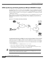
Configuring Wholesale Dial Performance Optimization
DC-758
Wholesale Dial Performance Optimization Feature Overview
How to Configure Automatic Command Execution
DC-758
DC-759
How to Configure TCP Clear Performance Optimization
DC-759
Verifying Configuration of TCP Clear Performance Optimization
DC-760
DIAL ACCESS SCENARIOS
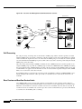
Dial Networking Business Applications
DC-762
Dial Networking for Service Providers and Enterprises
Common Dial Applications
DC-762
DC-765
IP Address Strategies DC-766
Choosing an Addressing Scheme DC-766
Classic IP Addressing DC-766
Cisco Easy IP DC-767
Enterprise Dial Scenarios and Configurations
Remote User Demographics
Demand and Scalability
DC-770
DC-770
DC-771
Remote Offices and Telecommuters Dialing In to a Central Site DC-771
Network Topologies DC-771
Dial-In Scenarios DC-772
Cisco 1604 Remote Office Router Dialing In to a Cisco 3620 Access Router DC-773
Remote Office Router Dialing In to a Cisco 3620 Router DC-776
Cisco 700 Series Router Using Port Address Translation to Dial In to a Cisco AS5300 Access
Server DC-779
Cisco 3640 Central Site Router Configuration to Support ISDN and Modem Calls DC-783
Cisco AS5300 Central Site Configuration Using Remote Security DC-785
Bidirectional Dial Between Central Sites and Remote Offices DC-788
Dial-In and Dial-Out Network Topology DC-788
Dialer Profiles and Virtual Profiles DC-789
Running Access Server Configurations DC-791
Cisco AS5300 Access Server Configuration with Dialer Profiles DC-792
Cisco 1604 ISDN Router Configuration with Dialer Profiles DC-797
Cisco 1604 Router Asynchronous Configuration with Dialer Profiles DC-798
Cisco AS5300 Access Server Configuration Without Dialer Profiles DC-799
Cisco 1604 ISDN Router Configuration Without Dialer Profiles DC-801
Cisco 1604 Router Asynchronous Configuration Without Dialer Profiles DC-802
Large-Scale Dial-In Configuration Using Virtual Profiles DC-803
xxxiii
Contents
Telecommuters Dialing In to a Mixed Protocol Environment
Description DC-804
Enterprise Network Topology DC-806
Mixed Protocol Dial-In Scenarios DC-807
Cisco 7200 #1 Backbone Router DC-808
Cisco 7200 #2 Backbone Router DC-809
Cisco AS5300 Universal Access Server DC-810
Telco and ISP Dial Scenarios and Configurations
DC-803
DC-813
Small- to Medium-Scale POPs DC-813
Individual Remote PCs Using Analog Modems DC-814
Network Topology DC-814
Running Configuration for ISDN PRI DC-814
Running Configuration for Robbed-Bit Signaling DC-816
Individual PCs Using ISDN Terminal Adapters DC-818
Network Topology DC-818
Terminal Adapter Configuration Example DC-819
Mixture of ISDN and Analog Modem Calls DC-821
Combination of Modem and ISDN Dial-In Configuration Example
DC-821
Large-Scale POPs DC-823
Scaling Considerations DC-823
How Stacking Works DC-824
A Typical Multilink PPP Session DC-824
Using Multichassis Multilink PPP DC-825
Setting Up an Offload Server DC-826
Using the Stack Group Bidding Protocol DC-827
Using L2F DC-828
Stack Group of Access Servers Using MMP with an Offload Processor Examples
Cisco Access Server #1 DC-828
Cisco Access Server #2 DC-830
Cisco Access Server #3 DC-832
Cisco 7206 as Offload Server DC-835
RADIUS Remote Security Examples DC-836
User Setup for PPP DC-837
User Setup for PPP and Static IP Address DC-837
Enabling Router Dial-In DC-837
User Setup for SLIP DC-837
User Setup for SLIP and Static IP Address DC-838
Using Telnet to connect to a UNIX Host DC-838
Automatic rlogin to UNIX Host DC-838
xxxiv
DC-828
Contents
PPP Calls over X.25 Networks DC-838
Overview DC-839
Remote PC Browsing Network Topology DC-839
Protocol Translation Configuration Example DC-840
APPENDIXES
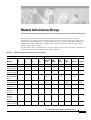
Modem Initialization Strings
Sample Modem Scripts
DC-843
DC-846
INDEX
xxxv
Contents
xxxvi
About Cisco IOS Software Documentation
This chapter discusses the objectives, audience, organization, and conventions of Cisco IOS software
documentation. It also provides sources for obtaining documentation from Cisco Systems.
Documentation Objectives
Cisco IOS software documentation describes the tasks and commands necessary to configure and
maintain Cisco networking devices.
Audience
The Cisco IOS software documentation set is intended primarily for users who configure and maintain
Cisco networking devices (such as routers and switches) but who may not be familiar with the tasks,
the relationship between tasks, or the Cisco IOS software commands necessary to perform particular
tasks. The Cisco IOS software documentation set is also intended for those users experienced with
Cisco IOS software who need to know about new features, new configuration options, and new software
characteristics in the current Cisco IOS software release.
Documentation Organization
The Cisco IOS software documentation set consists of documentation modules and master indexes. In
addition to the main documentation set, there are supporting documents and resources.
Documentation Modules
The Cisco IOS documentation modules consist of configuration guides and corresponding command
reference publications. Chapters in a configuration guide describe protocols, configuration tasks, and
Cisco IOS software functionality and contain comprehensive configuration examples. Chapters in a
command reference publication provide complete Cisco IOS command syntax information. Use each
configuration guide in conjunction with its corresponding command reference publication.
Cisco IOS Dial Technologies Configuration Guide
xxxvii
About Cisco IOS Software Documentation
Documentation Organization
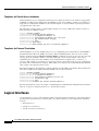
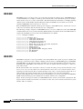
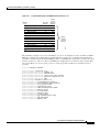
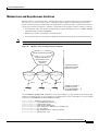
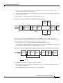
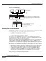
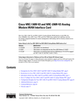
Figure 1 shows the Cisco IOS software documentation modules.
Note
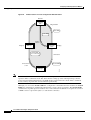
Figure 1
The abbreviations (for example, FC and FR) next to the book icons are page designators,
which are defined in a key in the index of each document to help you with navigation. The
bullets under each module list the major technology areas discussed in the corresponding
books.
Cisco IOS Software Documentation Modules
IPC
FC
Cisco IOS
Configuration
Fundamentals
Configuration
Guide
Cisco IOS
Configuration
Fundamentals
Command
Reference
FR
IP2R
Module FC/FR:
• Cisco IOS User
Interfaces
• File Management
• System Management
WC
WR
Cisco IOS
Wide-Area
Networking
Command
Reference
Cisco IOS
IP Command
Reference,
Volume 1 of 3:
Addressing
and Services
Cisco IOS
IP Command
Reference,
Volume 2 of 3:
Routing
Protocols
P2C
IP3R
Cisco IOS
IP Command
Reference,
Volume 3 of 3:
Multicast
Cisco IOS
Interface
Configuration
Guide
IR
P3C
Cisco IOS
AppleTalk and
Novell IPX
Configuration
Guide
P2R
Module IC/IR:
• LAN Interfaces
• Serial Interfaces
• Logical Interfaces
P3R
Module P2C/P2R:
• AppleTalk
• Novell IPX
MWC
Cisco IOS
Interface
Command
Reference
Cisco IOS
AppleTalk and
Novell IPX
Command
Reference
Cisco IOS
Mobile
Wireless
Configuration
Guide
MWR
Cisco IOS
Mobile
Wireless
Command
Reference
Module MWC/MWR:
• General Packet
Radio Service
Cisco IOS
Apollo Domain,
Banyan VINES,
DECnet, ISO
CLNS, and XNS
Configuration
Guide
SC
Cisco IOS
Apollo Domain,
Banyan VINES,
DECnet, ISO
CLNS, and XNS
Command
Reference
Module P3C/P3R:
• Apollo Domain
• Banyan VINES
• DECnet
• ISO CLNS
• XNS
Cisco IOS
Security
Configuration
Guide
SR
Cisco IOS
Security
Command
Reference
Module SC/SR:
• AAA Security Services
• Security Server Protocols
• Traffic Filtering and Firewalls
• IP Security and Encryption
• Passwords and Privileges
• Neighbor Router Authentication
• IP Security Options
• Supported AV Pairs
47953
Module WC/WR:
• ATM
• Broadband Access
• Frame Relay
• SMDS
• X.25 and LAPB
IP1R
Module IPC/IP1R/IP2R/IP3R:
• IP Addressing and Services
• IP Routing Protocols
• IP Multicast
IC
Cisco IOS
Wide-Area
Networking
Configuration
Guide
Cisco IOS
IP
Configuration
Guide
Cisco IOS Dial Technologies Configuration Guide
xxxviii
About Cisco IOS Software Documentation
Documentation Organization
Cisco IOS
Dial
Technologies
Configuration
Guide
TC
BC
Cisco IOS
Terminal
Services
Configuration
Guide
Cisco IOS
Bridging and
IBM Networking
Configuration
Guide
B2R
B1R
DR
Cisco IOS
Dial
Technologies
Command
Reference
TR
Module DC/DR:
• Preparing for Dial Access
• Modem and Dial Shelf Configuration
and Management
• ISDN Configuration
• Signalling Configuration
• Dial-on-Demand Routing
Configuration
• Dial-Backup Configuration
• Dial-Related Addressing Services
• Virtual Templates, Profiles, and
Networks
• PPP Configuration
• Callback and Bandwidth Allocation
Configuration
• Dial Access Specialized Features
• Dial Access Scenarios
VC
Cisco IOS
Voice, Video,
and Fax
Configuration
Guide
VR
Cisco IOS
Voice, Video,
and Fax
Command
Reference
Module VC/VR:
• Voice over IP
• Call Control Signalling
• Voice over
Frame Relay
• Voice over ATM
• Telephony Applications
• Trunk Management
• Fax, Video, and
Modem Support
Cisco IOS
Terminal
Services
Command
Reference
Module TC/TR:
• ARA
• LAT
• NASI
• Telnet
• TN3270
• XRemote
• X.28 PAD
• Protocol Translation
QC
Cisco IOS
Quality of
Service
Solutions
Configuration
Guide
QR
Cisco IOS
Quality of
Service
Solutions
Command
Reference
Module QC/QR:
• Packet Classification
• Congestion Management
• Congestion Avoidance
• Policing and Shaping
• Signalling
• Link Efficiency
Mechanisms
Cisco IOS
Bridging
and IBM
Networking
Command
Reference,
Volume 1 of 2
Cisco IOS
Bridging
and IBM
Networking
Command
Reference,
Volume 2 of 2
Module BC/B1R:
• Transparent
Bridging
• SRB
• Token Ring
Inter-Switch Link
• Token Ring Route
Switch Module
• RSRB
• DLSw+
• Serial Tunnel and
Block Serial Tunnel
• LLC2 and SDLC
• IBM Network
Media Translation
• SNA Frame Relay
Access
• NCIA Client/Server
• Airline Product Set
XC
Module BC/B2R:
• DSPU and SNA
Service Point
• SNA Switching
Services
• Cisco Transaction
Connection
• Cisco Mainframe
Channel Connection
• CLAW and TCP/IP
Offload
• CSNA, CMPC,
and CMPC+
• TN3270 Server
Cisco IOS
Switching
Services
Configuration
Guide
XR
Cisco IOS
Switching
Services
Command
Reference
Module XC/XR:
• Cisco IOS
Switching Paths
• NetFlow Switching
• Multiprotocol Label Switching
• Multilayer Switching
• Multicast Distributed Switching
• Virtual LANs
• LAN Emulation
47954
DC
Cisco IOS Dial Technologies Configuration Guide
xxxix
About Cisco IOS Software Documentation
Documentation Organization
Master Indexes
Two master indexes provide indexing information for the Cisco IOS software documentation set:
an index for the configuration guides and an index for the command references. Individual books also
contain a book-specific index.
The master indexes provide a quick way for you to find a command when you know the command name
but not which module contains the command. When you use the online master indexes, you can click
the page number for an index entry and go to that page in the online document.
Supporting Documents and Resources
The following documents and resources support the Cisco IOS software documentation set:
•
Cisco IOS Command Summary (two volumes)—This publication explains the function and syntax
of the Cisco IOS software commands. For more information about defaults and usage guidelines,
refer to the Cisco IOS command reference publications.
•
Cisco IOS System Error Messages—This publication lists and describes Cisco IOS system error
messages. Not all system error messages indicate problems with your system. Some are purely
informational, and others may help diagnose problems with communications lines, internal
hardware, or the system software.
•
Cisco IOS Debug Command Reference—This publication contains an alphabetical listing of the
debug commands and their descriptions. Documentation for each command includes a brief
description of its use, command syntax, usage guidelines, and sample output.
•
Dictionary of Internetworking Terms and Acronyms—This Cisco publication compiles and defines
the terms and acronyms used in the internetworking industry.
•
New feature documentation—The Cisco IOS software documentation set documents the mainline
release of Cisco IOS software (for example, Cisco IOS Release 12.2). New software features are
introduced in early deployment releases (for example, the Cisco IOS “T” release train for 12.2,
12.2(x)T). Documentation for these new features can be found in standalone documents called
“feature modules.” Feature module documentation describes new Cisco IOS software and hardware
networking functionality and is available on Cisco.com and the Documentation CD-ROM.
•
Release notes—This documentation describes system requirements, provides information about
new and changed features, and includes other useful information about specific software releases.
See the section “Using Software Release Notes” in the chapter “Using Cisco IOS Software” for
more information.
•
Caveats documentation—This documentation provides information about Cisco IOS software
defects in specific software releases.
•
RFCs—RFCs are standards documents maintained by the Internet Engineering Task Force (IETF).
Cisco IOS software documentation references supported RFCs when applicable. The full text of
referenced RFCs may be obtained on the World Wide Web at http://www.rfc-editor.org/.
•
MIBs—MIBs are used for network monitoring. For lists of supported MIBs by platform and
release, and to download MIB files, see the Cisco MIB website on Cisco.com at
http://www.cisco.com/public/sw-center/netmgmt/cmtk/mibs.shtml.
Cisco IOS Dial Technologies Configuration Guide
xl
About Cisco IOS Software Documentation
New and Changed Information
New and Changed Information
For Cisco IOS Release 12.2, two previous Release 12.1 guides, Cisco IOS Dial Services Configuration
Guide: Terminal Services and Cisco IOS Dial Services Configuration Guide: Network Services, have
been renamed and reorganized into a single book: Cisco IOS Dial Technologies Configuration Guide.
See Figure 1 for a list of the contents.
For Cisco IOS Release 12.2, the Release 12.1 Cisco IOS Dial Services Command Reference has been
renamed Cisco IOS Dial Technologies Command Reference.
The Cisco IOS Terminal Services Configuration Guide and Cisco IOS Terminal Services Command
Reference were extracted from the 12.1 release of the Cisco IOS Dial Services Configuration Guide:
Terminal Services and Cisco IOS Dial Services Command Reference, and placed in separate books not
included in this set.
Document Conventions
Within Cisco IOS software documentation, the term router is generally used to refer to a variety of Cisco
products (for example, routers, access servers, and switches). Routers, access servers, and other
networking devices that support Cisco IOS software are shown interchangeably within examples. These
products are used only for illustrative purposes; that is, an example that shows one product does not
necessarily indicate that other products are not supported.
The Cisco IOS documentation set uses the following conventions:
Convention
Description
^ or Ctrl
The ^ and Ctrl symbols represent the Control key. For example, the key combination ^D or Ctrl-D
means hold down the Control key while you press the D key. Keys are indicated in capital letters but
are not case sensitive.
string
A string is a nonquoted set of characters shown in italics. For example, when setting an SNMP
community string to public, do not use quotation marks around the string or the string will include the
quotation marks.
Command syntax descriptions use the following conventions:
Convention
Description
boldface
Boldface text indicates commands and keywords that you enter literally as shown.
italics
Italic text indicates arguments for which you supply values.
[x]
Square brackets enclose an optional element (keyword or argument).
|
A vertical line indicates a choice within an optional or required set of keywords or arguments.
[x | y]
Square brackets enclosing keywords or arguments separated by a vertical line indicate an optional
choice.
{x | y}
Braces enclosing keywords or arguments separated by a vertical line indicate a required choice.
Cisco IOS Dial Technologies Configuration Guide
xli
About Cisco IOS Software Documentation
Obtaining Documentation
Nested sets of square brackets or braces indicate optional or required choices within optional or
required elements. For example:
Convention
Description
[x {y | z}]
Braces and a vertical line within square brackets indicate a required choice within an optional element.
Examples use the following conventions:
Convention
Description
screen
Examples of information displayed on the screen are set in Courier font.
boldface screen
Examples of text that you must enter are set in Courier bold font.
<
Angle brackets enclose text that is not printed to the screen, such as passwords.
>
!
[
An exclamation point at the beginning of a line indicates a comment line. (Exclamation points are also
displayed by the Cisco IOS software for certain processes.)
]
Square brackets enclose default responses to system prompts.
The following conventions are used to attract the attention of the reader:
Caution
Note
Timesaver
Means reader be careful. In this situation, you might do something that could result in
equipment damage or loss of data.
Means reader take note. Notes contain helpful suggestions or references to materials not
contained in this manual.
Means the described action saves time. You can save time by performing the action
described in the paragraph.
Obtaining Documentation
The following sections provide sources for obtaining documentation from Cisco Systems.
World Wide Web
The most current Cisco documentation is available on the World Wide Web at the following website:
http://www.cisco.com
Translated documentation is available at the following website:
http://www.cisco.com/public/countries_languages.html
Cisco IOS Dial Technologies Configuration Guide
xlii
About Cisco IOS Software Documentation
Documentation Feedback
Documentation CD-ROM
Cisco documentation and additional literature are available in a CD-ROM package, which ships
with your product. The Documentation CD-ROM is updated monthly and may be more current than
printed documentation. The CD-ROM package is available as a single unit or through an
annual subscription.
Ordering Documentation
Cisco documentation can be ordered in the following ways:
•
Registered Cisco Direct Customers can order Cisco product documentation from the Networking
Products MarketPlace:
http://www.cisco.com/cgi-bin/order/order_root.pl
•
Registered Cisco.com users can order the Documentation CD-ROM through the online
Subscription Store:
http://www.cisco.com/go/subscription
•
Nonregistered Cisco.com users can order documentation through a local account representative by
calling Cisco corporate headquarters (California, USA) at 408 526-7208 or, in North America, by
calling 800 553-NETS(6387).
Documentation Feedback
If you are reading Cisco product documentation on the World Wide Web, you can submit technical
comments electronically. Click Feedback in the toolbar and select Documentation. After you complete
the form, click Submit to send it to Cisco.
You can e-mail your comments to [email protected].
To submit your comments by mail, use the response card behind the front cover of your document, or
write to the following address:
Cisco Systems, Inc.
Document Resource Connection
170 West Tasman Drive
San Jose, CA 95134-9883
We appreciate your comments.
Obtaining Technical Assistance
Cisco provides Cisco.com as a starting point for all technical assistance. Customers and partners can
obtain documentation, troubleshooting tips, and sample configurations from online tools. For
Cisco.com registered users, additional troubleshooting tools are available from the TAC website.
Cisco IOS Dial Technologies Configuration Guide
xliii
About Cisco IOS Software Documentation
Obtaining Technical Assistance
Cisco.com
Cisco.com is the foundation of a suite of interactive, networked services that provides immediate, open
access to Cisco information and resources at anytime, from anywhere in the world. This highly
integrated Internet application is a powerful, easy-to-use tool for doing business with Cisco.
Cisco.com provides a broad range of features and services to help customers and partners streamline
business processes and improve productivity. Through Cisco.com, you can find information about Cisco
and our networking solutions, services, and programs. In addition, you can resolve technical issues with
online technical support, download and test software packages, and order Cisco learning materials and
merchandise. Valuable online skill assessment, training, and certification programs are also available.
Customers and partners can self-register on Cisco.com to obtain additional personalized information
and services. Registered users can order products, check on the status of an order, access technical
support, and view benefits specific to their relationships with Cisco.
To access Cisco.com, go to the following website:
http://www.cisco.com
Technical Assistance Center
The Cisco TAC website is available to all customers who need technical assistance with a Cisco product
or technology that is under warranty or covered by a maintenance contract.
Contacting TAC by Using the Cisco TAC Website
If you have a priority level 3 (P3) or priority level 4 (P4) problem, contact TAC by going to the TAC
website:
http://www.cisco.com/tac
P3 and P4 level problems are defined as follows:
•
P3—Your network performance is degraded. Network functionality is noticeably impaired, but
most business operations continue.
•
P4—You need information or assistance on Cisco product capabilities, product installation, or basic
product configuration.
In each of the above cases, use the Cisco TAC website to quickly find answers to your questions.
To register for Cisco.com, go to the following website:
http://www.cisco.com/register/
If you cannot resolve your technical issue by using the TAC online resources, Cisco.com registered
users can open a case online by using the TAC Case Open tool at the following website:
http://www.cisco.com/tac/caseopen
Contacting TAC by Telephone
If you have a priority level 1 (P1) or priority level 2 (P2) problem, contact TAC by telephone and
immediately open a case. To obtain a directory of toll-free numbers for your country, go to the following
website:
http://www.cisco.com/warp/public/687/Directory/DirTAC.shtml
Cisco IOS Dial Technologies Configuration Guide
xliv
About Cisco IOS Software Documentation
Obtaining Technical Assistance
P1 and P2 level problems are defined as follows:
•
P1—Your production network is down, causing a critical impact to business operations if service
is not restored quickly. No workaround is available.
•
P2—Your production network is severely degraded, affecting significant aspects of your business
operations. No workaround is available.
Cisco IOS Dial Technologies Configuration Guide
xlv
About Cisco IOS Software Documentation
Obtaining Technical Assistance
Cisco IOS Dial Technologies Configuration Guide
xlvi
Using Cisco IOS Software
This chapter provides helpful tips for understanding and configuring Cisco IOS software using the
command-line interface (CLI). It contains the following sections:
•
Understanding Command Modes
•
Getting Help
•
Using the no and default Forms of Commands
•
Saving Configuration Changes
•
Filtering Output from the show and more Commands
•
Identifying Supported Platforms
For an overview of Cisco IOS software configuration, refer to the Cisco IOS Configuration
Fundamentals Configuration Guide.
For information on the conventions used in the Cisco IOS software documentation set, see the chapter
“About Cisco IOS Software Documentation” located at the beginning of this book.
Understanding Command Modes
You use the CLI to access Cisco IOS software. Because the CLI is divided into many different modes,
the commands available to you at any given time depend on the mode you are currently in. Entering a
question mark (?) at the CLI prompt allows you to obtain a list of commands available for each
command mode.
When you log in to the CLI, you are in user EXEC mode. User EXEC mode contains only a limited
subset of commands. To have access to all commands, you must enter privileged EXEC mode, normally
by using a password. From privileged EXEC mode you can issue any EXEC command—user or
privileged mode—or you can enter global configuration mode. Most EXEC commands are one-time
commands. For example, show commands show important status information, and clear commands
clear counters or interfaces. The EXEC commands are not saved when the software reboots.
Configuration modes allow you to make changes to the running configuration. If you later save the
running configuration to the startup configuration, these changed commands are stored when the
software is rebooted. To enter specific configuration modes, you must start at global configuration
mode. From global configuration mode, you can enter interface configuration mode and a variety of
other modes, such as protocol-specific modes.
ROM monitor mode is a separate mode used when the Cisco IOS software cannot load properly. If a
valid software image is not found when the software boots or if the configuration file is corrupted at
startup, the software might enter ROM monitor mode.
Cisco IOS Dial Technologies Configuration Guide
xlvii
Using Cisco IOS Software
Getting Help
Table 1 describes how to access and exit various common command modes of the Cisco IOS software.
It also shows examples of the prompts displayed for each mode.
Table 1
Accessing and Exiting Command Modes
Command
Mode
Access Method
Prompt
Exit Method
User EXEC
Log in.
Router>
Use the logout command.
Privileged
EXEC
From user EXEC mode,
use the enable EXEC
command.
Router#
To return to user EXEC mode, use the disable
command.
Global
configuration
From privileged EXEC
mode, use the configure
terminal privileged
EXEC command.
Router(config)#
To return to privileged EXEC mode from global
configuration mode, use the exit or end command,
or press Ctrl-Z.
Interface
configuration
From global
configuration mode,
specify an interface using
an interface command.
Router(config-if)#
To return to global configuration mode, use the exit
command.
From privileged EXEC
mode, use the reload
EXEC command. Press
the Break key during the
first 60 seconds while the
system is booting.
>
ROM monitor
To return to privileged EXEC mode, use the end
command, or press Ctrl-Z.
To exit ROM monitor mode, use the continue
command.
For more information on command modes, refer to the “Using the Command-Line Interface” chapter in
the Cisco IOS Configuration Fundamentals Configuration Guide.
Getting Help
Entering a question mark (?) at the CLI prompt displays a list of commands available for each command
mode. You can also get a list of keywords and arguments associated with any command by using the
context-sensitive help feature.
To get help specific to a command mode, a command, a keyword, or an argument, use one of the
following commands:
Command
Purpose
help
Provides a brief description of the help system in any command mode.
abbreviated-command-entry?
Provides a list of commands that begin with a particular character string. (No space
between command and question mark.)
abbreviated-command-entry<Tab>
Completes a partial command name.
?
Lists all commands available for a particular command mode.
command ?
Lists the keywords or arguments that you must enter next on the command line.
(Space between command and question mark.)
Cisco IOS Dial Technologies Configuration Guide
xlviii
Using Cisco IOS Software
Getting Help
Example: How to Find Command Options
This section provides an example of how to display syntax for a command. The syntax can consist of
optional or required keywords and arguments. To display keywords and arguments for a command, enter
a question mark (?) at the configuration prompt or after entering part of a command followed by a space.
The Cisco IOS software displays a list and brief description of available keywords and arguments. For
example, if you were in global configuration mode and wanted to see all the keywords or arguments for
the arap command, you would type arap ?.
The <cr> symbol in command help output stands for “carriage return.” On older keyboards, the carriage
return key is the Return key. On most modern keyboards, the carriage return key is the Enter key. The
<cr> symbol at the end of command help output indicates that you have the option to press Enter to
complete the command and that the arguments and keywords in the list preceding the <cr> symbol are
optional. The <cr> symbol by itself indicates that no more arguments or keywords are available and that
you must press Enter to complete the command.
Table 2 shows examples of how you can use the question mark (?) to assist you in entering commands.
The table steps you through configuring an IP address on a serial interface on a Cisco 7206 router that
is running Cisco IOS Release 12.0(3).
Table 2
How to Find Command Options
Command
Comment
Router> enable
Password: <password>
Router#
Enter the enable command and
password to access privileged EXEC
commands. You are in privileged
EXEC mode when the prompt changes
to Router#.
Router# configure terminal
Enter configuration commands, one per line. End with CNTL/Z.
Router(config)#
Enter the configure terminal
privileged EXEC command to enter
global configuration mode. You are in
global configuration mode when the
prompt changes to Router(config)#.
Router(config)# interface serial ?
<0-6>
Serial interface number
Router(config)# interface serial 4 ?
/
Router(config)# interface serial 4/ ?
<0-3>
Serial interface number
Router(config)# interface serial 4/0
Router(config-if)#
Enter interface configuration mode by
specifying the serial interface that you
want to configure using the interface
serial global configuration command.
Enter ? to display what you must enter
next on the command line. In this
example, you must enter the serial
interface slot number and port number,
separated by a forward slash.
You are in interface configuration mode
when the prompt changes to
Router(config-if)#.
Cisco IOS Dial Technologies Configuration Guide
xlix
Using Cisco IOS Software
Getting Help
Table 2
How to Find Command Options (continued)
Command
Comment
Router(config-if)# ?
Interface configuration commands:
.
.
.
ip
Interface Internet Protocol config commands
keepalive
Enable keepalive
lan-name
LAN Name command
llc2
LLC2 Interface Subcommands
load-interval
Specify interval for load calculation for an
interface
locaddr-priority
Assign a priority group
logging
Configure logging for interface
loopback
Configure internal loopback on an interface
mac-address
Manually set interface MAC address
mls
mls router sub/interface commands
mpoa
MPOA interface configuration commands
mtu
Set the interface Maximum Transmission Unit (MTU)
netbios
Use a defined NETBIOS access list or enable
name-caching
no
Negate a command or set its defaults
nrzi-encoding
Enable use of NRZI encoding
ntp
Configure NTP
.
.
.
Router(config-if)#
Enter ? to display a list of all the
interface configuration commands
available for the serial interface. This
example shows only some of the
available interface configuration
commands.
Router(config-if)# ip ?
Interface IP configuration subcommands:
access-group
Specify access control for packets
accounting
Enable IP accounting on this interface
address
Set the IP address of an interface
authentication
authentication subcommands
bandwidth-percent
Set EIGRP bandwidth limit
broadcast-address
Set the broadcast address of an interface
cgmp
Enable/disable CGMP
directed-broadcast Enable forwarding of directed broadcasts
dvmrp
DVMRP interface commands
hello-interval
Configures IP-EIGRP hello interval
helper-address
Specify a destination address for UDP broadcasts
hold-time
Configures IP-EIGRP hold time
.
.
.
Router(config-if)# ip
Enter the command that you want to
configure for the interface. This
example uses the ip command.
Cisco IOS Dial Technologies Configuration Guide
l
Enter ? to display what you must enter
next on the command line. This
example shows only some of the
available interface IP configuration
commands.
Using Cisco IOS Software
Using the no and default Forms of Commands
Table 2
How to Find Command Options (continued)
Command
Comment
Router(config-if)# ip address ?
A.B.C.D
IP address
negotiated
IP Address negotiated over PPP
Router(config-if)# ip address
Enter the command that you want to
configure for the interface. This
example uses the ip address command.
Enter ? to display what you must enter
next on the command line. In this
example, you must enter an IP address
or the negotiated keyword.
A carriage return (<cr>) is not
displayed; therefore, you must enter
additional keywords or arguments to
complete the command.
Enter the keyword or argument you
want to use. This example uses the
172.16.0.1 IP address.
Router(config-if)# ip address 172.16.0.1 ?
A.B.C.D
IP subnet mask
Router(config-if)# ip address 172.16.0.1
Enter ? to display what you must enter
next on the command line. In this
example, you must enter an IP subnet
mask.
A <cr> is not displayed; therefore, you
must enter additional keywords or
arguments to complete the command.
Router(config-if)# ip address 172.16.0.1 255.255.255.0 ?
secondary
Make this IP address a secondary address
<cr>
Router(config-if)# ip address 172.16.0.1 255.255.255.0
Enter the IP subnet mask. This example
uses the 255.255.255.0 IP subnet mask.
Enter ? to display what you must enter
next on the command line. In this
example, you can enter the secondary
keyword, or you can press Enter.
A <cr> is displayed; you can press
Enter to complete the command, or
you can enter another keyword.
Router(config-if)# ip address 172.16.0.1 255.255.255.0
Router(config-if)#
In this example, Enter is pressed to
complete the command.
Using the no and default Forms of Commands
Almost every configuration command has a no form. In general, use the no form to disable a function.
Use the command without the no keyword to reenable a disabled function or to enable a function that
is disabled by default. For example, IP routing is enabled by default. To disable IP routing, use the no
ip routing command; to reenable IP routing, use the ip routing command. The Cisco IOS software
command reference publications provide the complete syntax for the configuration commands and
describe what the no form of a command does.
Configuration commands also can have a default form, which returns the command settings to the
default values. Most commands are disabled by default, so in such cases using the default form has the
same result as using the no form of the command. However, some commands are enabled by default and
Cisco IOS Dial Technologies Configuration Guide
li
Using Cisco IOS Software
Saving Configuration Changes
have variables set to certain default values. In these cases, the default form of the command enables the
command and sets the variables to their default values. The Cisco IOS software command reference
publications describe the effect of the default form of a command if the command functions differently
than the no form.
Saving Configuration Changes
Use the copy system:running-config nvram:startup-config command to save your configuration
changes to the startup configuration so that the changes will not be lost if the software reloads or a
power outage occurs. For example:
Router# copy system:running-config nvram:startup-config
Building configuration...
It might take a minute or two to save the configuration. After the configuration has been saved, the
following output appears:
[OK]
Router#
On most platforms, this task saves the configuration to NVRAM. On the Class A Flash file system
platforms, this task saves the configuration to the location specified by the CONFIG_FILE environment
variable. The CONFIG_FILE variable defaults to NVRAM.
Filtering Output from the show and more Commands
In Cisco IOS Release 12.0(1)T and later releases, you can search and filter the output of show and more
commands. This functionality is useful if you need to sort through large amounts of output or if you
want to exclude output that you need not see.
To use this functionality, enter a show or more command followed by the “pipe” character (|); one of
the keywords begin, include, or exclude; and a regular expression on which you want to search or filter
(the expression is case-sensitive):
command | {begin | include | exclude} regular-expression
The output matches certain lines of information in the configuration file. The following example
illustrates how to use output modifiers with the show interface command when you want the output to
include only lines in which the expression “protocol” appears:
Router# show interface | include protocol
FastEthernet0/0 is up, line protocol is up
Serial4/0 is up, line protocol is up
Serial4/1 is up, line protocol is up
Serial4/2 is administratively down, line protocol is down
Serial4/3 is administratively down, line protocol is down
For more information on the search and filter functionality, refer to the “Using the Command-Line
Interface” chapter in the Cisco IOS Configuration Fundamentals Configuration Guide, Release 12.2.
Cisco IOS Dial Technologies Configuration Guide
lii
Using Cisco IOS Software
Identifying Supported Platforms
Identifying Supported Platforms
Cisco IOS software is packaged in feature sets consisting of software images that support specific
platforms. The feature sets available for a specific platform depend on which Cisco IOS software
images are included in a release. To identify the set of software images available in a specific release
or to find out if a feature is available in a given Cisco IOS software image, see the following sections:
•
Using Feature Navigator
•
Using Software Release Notes
Using Feature Navigator
Feature Navigator is a web-based tool that enables you to quickly determine which Cisco IOS software
images support a particular set of features and which features are supported in a particular Cisco IOS
image.
Feature Navigator is available 24 hours a day, 7 days a week. To access Feature Navigator, you must
have an account on Cisco.com. If you have forgotten or lost your account information, e-mail the
Contact Database Administration group at [email protected]. If you do not have an account on
Cisco.com, go to http://www.cisco.com/register and follow the directions to establish an account.
To use Feature Navigator, you must have a JavaScript-enabled web browser such as Netscape 3.0 or
later, or Internet Explorer 4.0 or later. Internet Explorer 4.0 always has JavaScript enabled. To enable
JavaScript for Netscape 3.x or Netscape 4.x, follow the instructions provided with the web browser. For
JavaScript support and enabling instructions for other browsers, check with the browser vendor.
Feature Navigator is updated when major Cisco IOS software releases and technology releases occur.
You can access Feature Navigator at the following URL:
http://www.cisco.com/go/fn
Using Software Release Notes
Cisco IOS software releases include release notes that provide the following information:
•
Platform support information
•
Memory recommendations
•
Microcode support information
•
Feature set tables
•
Feature descriptions
•
Open and resolved severity 1 and 2 caveats for all platforms
Release notes are intended to be release-specific for the most current release, and the information
provided in these documents may not be cumulative in providing information about features that first
appeared in previous releases.
Cisco IOS Dial Technologies Configuration Guide
liii
Using Cisco IOS Software
Identifying Supported Platforms
Cisco IOS Dial Technologies Configuration Guide
liv
Dial Interfaces, Controllers, and
Lines
Overview of Dial Interfaces, Controllers, and
Lines
This chapter describes the different types of software constructs, interfaces, controllers, channels, and
lines that are used for dial-up remote access. It includes the following main sections:
•
Cisco IOS Dial Components
•
Logical Constructs
•
Logical Interfaces
•
Circuit-Switched Digital Calls
•
T1 and E1 Controllers
•
Non-ISDN Channelized T1 and Channelized E1 Lines
•
ISDN Service
•
Line Types
•
Encapsulation Types
For a complete description of the commands in this chapter, refer to the Cisco IOS Dial Technologies
Command Reference. To locate documentation of other commands that appear in this chapter, use the
command reference master index or search online.
Cisco IOS Dial Components
Different components inside Cisco IOS software work together to enable remote clients to dial in and
send packets. Figure 2 shows one Cisco AS5300 access server that is receiving calls from a remote
office, branch office (ROBO); small office, home office (SOHO); and modem client.
Depending on your network scenario, you may encounter all of the components in Figure 2. For
example, you might decide to create a virtual IP subnet by using a loopback interface. This step saves
address space. Virtual subnets can exist inside devices that you advertise to your backbone. In turn, IP
packets get relayed to remote PCs, which route back to the central site.
Cisco IOS Dial Technologies Configuration Guide
DC-2
Overview of Dial Interfaces, Controllers, and Lines
Cisco IOS Dial Components
Figure 2
Cisco IOS Dial Universe
Headquarters
intranet/Internet
Interface
virtual template
Interface
group-async
Cloning
Fast Ethernet
interface
Virtual
access
interface
Interface dialer
controlling the
D channels
Loopback
interface
Routing and
switching engine
Cloning
Cloning
Asynchronous
interfaces
Lines
Interface serial
channels S0:0, S0:1…
(B channels)
Modems
AAA
TDM bus
Controllers
Cisco IOS software
inside a Cisco AS5300
E1/T1 PRI ports
PRI lines
= ISDN B channel
PSTN/ISDN
= Modem/POTS
POTS
Cisco 1604
(ROBO)
POTS line
BRI
line
Modem
Cisco 766
(SOHO)
Remote
PC
14931
BRI
line
Cisco IOS Dial Technologies Configuration Guide
DC-3
Overview of Dial Interfaces, Controllers, and Lines
Logical Constructs
Logical Constructs
A logical construct stores core protocol characteristics to assign to physical interfaces. No data packets
are forwarded to a logical construct. Cisco uses three types of logical constructs in its access servers and
routers. These constructs are described in the following sections:
•
Asynchronous Interfaces
•
Group Asynchronous Interfaces
•
Virtual Template Interfaces
Asynchronous Interfaces
An asynchronous interface assigns network protocol characteristics to remote asynchronous clients that
are dialing in through physical terminal lines and modems. (See Figure 3.)
Use the interface async command to create and configure an asynchronous interface.
Figure 3
Logical Construct for an Asynchronous Interface
Asynchronous interface
Contains core protocol
characteristics for
incoming asynchronous
clients
Line 1
Modem 1
PSTN/ISDN
Remote PC
negotiating parameters
with the asynchronous
interface
14054
Modem
To enable clients to dial in, you must configure two asynchronous components: asynchronous lines and
asynchronous interfaces. Asynchronous interfaces correspond to physical terminal lines. For example,
asynchronous interface 1 corresponds to tty line 1.
Commands entered in asynchronous interface mode configure protocol-specific parameters for
asynchronous interfaces, whereas commands entered in line configuration configure the physical aspects
for the same port.
Cisco IOS Dial Technologies Configuration Guide
DC-4
Overview of Dial Interfaces, Controllers, and Lines
Logical Constructs
Specifically, you configure asynchronous interfaces to support PPP connections. An asynchronous
interface on an access server or router can be configured to support the following functions:
•
Network protocol support such as IP, Internet Protocol Exchange (IPX), or AppleTalk
•
Encapsulation support (such as PPP)
•
IP client addressing options (default or dynamic)
•
IPX network addressing options
•
PPP authentication
•
ISDN BRI and PRI configuration
For additional information about configuring asynchronous interfaces, see the chapter “Configuring
Asynchronous Lines and Interfaces.”
Group Asynchronous Interfaces
A group asynchronous interface is a parent interface that stores core protocol characteristics and projects
them to a specified range of asynchronous interfaces. Asynchronous interfaces clone protocol
information from group asynchronous interfaces. No data packets arrive in a group asynchronous
interface. By setting up a group asynchronous interface, you also eliminate the need to repeatedly
configure identical configuration information across several asynchronous interfaces.
See the “Overview of Modem Interfaces” chapter for more information about group asynchronous
interfaces.
Virtual Template Interfaces
A virtual template interface stores protocol configuration information for virtual access interfaces and
protocol translation sessions. (See Figure 4.)
Figure 4
Logical Construct for a Virtual Template Interface
Virtual template interface
Stores and projects
core protocol
configuration
information
Temporary
virtual access
interface
VPDN
session event
Protocol
translation
event
S6490
Multilink
session
event
Cisco IOS Dial Technologies Configuration Guide
DC-5
Overview of Dial Interfaces, Controllers, and Lines
Logical Interfaces
Templates for Virtual Access Interfaces
Virtual templates project configuration information to temporary virtual access interfaces triggered by
multilink or virtual private dial-up network (VPDN) session events. When a virtual access interface is
triggered, the configuration attributes in the virtual template are cloned and the negotiated parameters
are applied to the connection.
The following example shows a virtual template interface on a Cisco 7206 router, which is used as a
home gateway in a VPDN scenario:
Router# configure terminal
Router(config)# interface virtual-template 1
Router(config-if)# ip unnumbered ethernet 2/1
Router(config-if)# peer default ip address pool cisco-pool
Router(config-if)# ppp authentication chap pap
Router(config-if)# exit
Router(config)# vpdn enable
Router(config)# vpdn incoming isp cisco.com virtual-template 1
Templates for Protocol Translation
Virtual templates are used to simplify the process of configuring protocol translation to tunnel PPP or
Serial Line Internet Protocol (SLIP) across X.25, TCP, and LAT networks. You can create a virtual
interface template using the interface virtual-template command, and you can use it for one-step and
two-step protocol translation. When a user dials in through a vty line and a tunnel connection is
established, the router clones the attributes of the virtual interface template onto a virtual access
interface. This virtual access interface is a temporary interface that supports the protocol configuration
specified in the virtual interface template. This virtual access interface is created dynamically and lasts
only as long as the tunnel session is active.
The virtual template in the following example explicitly specifies PPP encapsulation. The translation is
from X.25 to PPP, which enables tunneling of PPP across an X.25 network.
Router# configure terminal
Router(config)# interface virtual-template 1
Router(config-if)# ip unnumbered ethernet 0
Router(config-if)# peer default ip address 172.18.2.131
Router(config-if)# encapsulation ppp
Router(config-if)# exit
Router(config)# translate x25 5555678 virtual-template 1
For more information, refer to the chapter “Configuring Protocol Translation and Virtual Asynchronous
Devices” in the Cisco IOS Terminal Services Configuration Guide.
Logical Interfaces
A logical interface receives and sends data packets and controls physical interfaces. Cisco IOS software
provides three logical interfaces used for dial access. These interfaces are described in the following
sections:
•
Dialer Interfaces
•
Virtual Access Interfaces
•
Virtual Asynchronous Interfaces
Cisco IOS Dial Technologies Configuration Guide
DC-6
Overview of Dial Interfaces, Controllers, and Lines
Logical Interfaces
Dialer Interfaces
A dialer interface is a parent interface that stores and projects protocol configuration information that is
common to all data (D) channels that are members of a dialer rotary group. Data packets pass through
dialer interfaces, which in turn initiate dialing for inbound calls. In most cases, D channels get their core
protocol intelligence from dialer interfaces.
Figure 5 shows packets coming into a dialer interface, which contains the configuration parameters
common to four D channels (shown as S0:0, S0:1, S0:2, and S0:3). All the D channels are members of
the same rotary group. Without the dialer interface configuration, each D channel must be manually
configured with identical properties. Dialer interfaces condense and streamline the configuration
process.
Figure 5
Dialer Interface and Its Neighboring Components
Incoming
data packets
Incoming
data packets
Dialer interface (parent)
S0:1
PRI 1
PRI 2
B channels B channels
S0:2
S0:3
PRI 3
PRI 4
B channels B channels
S6489
S0:0
A dialer interface is user configurable and linked to individual B channels, where it delivers data packets
to their physical destinations. Dialer interfaces seize physical interfaces to cause packet delivery. If a
dialer interface engages in a multilink session, a dialer interface is in control of a virtual access interface,
which in turn controls S0:3 or chassis 2 S0:3, for example. A dialer interface is created with the interface
dialer global configuration command.
The following example shows a fully configured dialer interface:
Router# configure terminal
Router(config)# interface dialer 0
Router(config-if)# ip unnumbered loopback 0
Router(config-if)# no ip mroute-cache
Router(config-if)# encapsulation ppp
Router(config-if)# peer default ip address pool dialin_pool
Router(config-if)# dialer in-band
Router(config-if)# dialer-group 1
Router(config-if)# no fair-queue
Router(config-if)# no cdp enable
Router(config-if)# ppp authentication chap pap callin
Router(config-if)# ppp multilink
All the D channels are members of rotary group 1.
Cisco IOS Dial Technologies Configuration Guide
DC-7
Overview of Dial Interfaces, Controllers, and Lines
Logical Interfaces
Virtual Access Interfaces
A virtual access interface is a temporary interface that is spawned to terminate incoming PPP streams
that have no physical connections. PPP streams, Layer 2 Forwarding Protocol (L2F), and Layer 2 Tunnel
Protocol (L2TP) frames that come in on multiple B channels are reassembled on virtual access
interfaces. These access interfaces are constructs used to terminate packets.
Virtual access interfaces obtain their set of instructions from virtual interface templates. The attributes
configured in virtual templates are projected or cloned to a virtual access interfaces. Virtual access
interfaces are not directly user configurable. These interfaces are created dynamically and last only as
long as the tunnels or multilink sessions are active. After the sessions end, the virtual access interfaces
disappear.
Figure 6 shows how a virtual access interface functions to accommodate a multilink session event. Two
physical interfaces on two different access servers are participating in one multilink call from a remote
PC. However, each Cisco AS5300 access server has only one B channel available to receive a call. All
other channels are busy. Therefore all four packets are equally dispersed across two separate B channels
and two access servers. Each Cisco AS5300 access server receives only half the total packets. A virtual
access interface is dynamically spawned upstream on a Cisco 7206 backhaul router to receive the
multilink protocol, track the multilink frames, and reassemble the packets. The Cisco 7206 router is
configured to be the bundle master, which performs all packet assembly and reassembly for both
Cisco AS5300 access servers.
Figure 6
Virtual Access Interfaces Used for Multichassis Multilink Session Events
PC sending data over
a PPP packet stream
Cisco 1600
remote office
router
4
3
2
BRI
1
Cisco AS5300.
One available B channel.
Receiving packets 1 and 2
Cisco AS5300.
One available B channel.
Receiving packets 3 and 4
PSTN/ISDN
2
4
1
3
HSSI/ATM
Cisco 7206 backhaul router.
Spawns all virtual access interfaces.
The dedicated bundlemaster.
Cisco IOS Dial Technologies Configuration Guide
DC-8
ISDN network
S6492
Fast
Ethernet
Overview of Dial Interfaces, Controllers, and Lines
Circuit-Switched Digital Calls
Virtual Asynchronous Interfaces
A virtual asynchronous interface is created on demand to support calls that enter the router through a
nonphysical interface. For example, asynchronous character stream calls terminate or land on
nonphysical interfaces. These types of calls include inbound Telnet, LAT, PPP over character-oriented
protocols (such as V.120 or X.25), and LAPB-TA and PAD calls. A virtual asynchronous interface is also
used to terminate L2F/L2TP tunnels, which are often traveling companions with Multilink protocol
sessions. Virtual asynchronous interfaces are not user configurable; rather, they are dynamically created
and torn down on demand. A virtual asynchronous line is used to access a virtual asynchronous interface.
Figure 7 shows a variety of calls that are terminating on a virtual asynchronous interface. After the calls
end, the interface is torn down.
Figure 7
Asynchronous Character Stream Calls Terminating on a Virtual Asynchronous Interface
PPP stream
coming in over
a V.120 line
Telnet call
X.25 PAD
call
Virtual asynchronous
interface
LAT call
S6488
L2F/L2TP tunnel
needing to be
terminated
Circuit-Switched Digital Calls
Circuit-switched digital calls are usually ISDN 56-kbps or 64-kbps data calls that use PPP. These calls
are initiated by an ISDN router, access server, or terminal adapter that is connected to a client
workstation. Individual synchronous serial digital signal level 0 (DS0) bearer (B) channels are used to
transport circuit-switched digital calls across WANs. These calls do not transmit across “old world”
lines.
Figure 8 shows a Cisco 1600 series remote office router dialing in to a Cisco 3640 router positioned at
a headquarters gateway.
Cisco IOS Dial Technologies Configuration Guide
DC-9
Overview of Dial Interfaces, Controllers, and Lines
T1 and E1 Controllers
Figure 8
Remote Office LAN Dialing In to Headquarters
PC sending e-mail
to headquarters
PPP
Hub
BRI
PRI
Fast
Ethernet
PSTN/ISDN
NT server
Cisco 3640
headquarters
gateway router
14053
Cisco 1600
remote office
router
PC
T1 and E1 Controllers
Cisco controllers negotiate the following parameters between an access server and a central office: line
coding, framing, clocking, DS0/time-slot provisioning, and signaling.
Time slots are provisioned to meet the needs of particular network scenarios. T1 controllers have
24 time slots, and E1 controllers have 30 time slots. To support traffic flow for one ISDN PRI line in a
T1 configuration, use the pri-group command. To support traffic flow for analog calls over a
channelized E1 line with recEive and transMit (E&M—also ear and mouth) signaling, use the cas-group
1 timeslots 1-30 type e&m-fgb command. Most telephone companies do not support provisioning one
trunk for different combinations of time-slot services, though this provisioning is supported on Cisco
controllers. On a T1 controller, for example, time slots 1 to 10 could run PRI, time slots 11 to 20 could
run channel-associated signaling (CAS), and time slots 21 to 24 could support leased-line grouping.
The following example configures one of four T1 controllers on a Cisco AS5300 access server:
Router# configure terminal
Router(config)# controller t1 ?
<0-3> Controller unit number
Router(config)# controller t1 0
Router(config-controller)# framing esf
Router(config-controller)# linecode b8zs
Router(config-controller)# clock source line primary
Router(config-controller)# pri-group timeslots 1-24
Router(config-controller)#
This example supports modem calls and circuit-switched digital calls over ISDN PRI.
Non-ISDN Channelized T1 and Channelized E1 Lines
A channelized T1 or channelized E1 line is an analog line that was originally intended to support analog
voice calls, but has evolved to support analog data calls. ISDN is not sent across channelized T1 or E1
lines. Channelized T1 and channelized E1 lines are often referred to as CT1 and CE1. These channelized
lines are found in “old world,” non-ISDN telephone networks.
Cisco IOS Dial Technologies Configuration Guide
DC-10
Overview of Dial Interfaces, Controllers, and Lines
ISDN Service
The difference between traditional channelized lines (analog) and nonchannelized lines (ISDN) is that
channelized lines have no built-in D channel. That is, all 24 channels on a T1 line carry only data. The
signaling is in-band or associated to the data channels. Traditional channelized lines do not support
digitized data calls (for example, BRI with 2B + D). Channelized lines support a variety of in-band signal
types, such as ground start, loop start, wink start, immediate start, E&M, and R2.
Signaling for channelized lines is configured with the cas-group controller configuration command. The
following example configures E&M group B signaling on a T1 controller:
Router# configure terminal
Router(config)# controller t1 0
Router(config-controller)# cas-group 1 timeslots 1-24 type ?
e&m-fgb
E & M Type II FGB
e&m-fgd
E & M Type II FGD
e&m-immediate-start E & M Immediate Start
fxs-ground-start
FXS Ground Start
fxs-loop-start
FXS Loop Start
r1-modified
R1 Modified
sas-ground-start
SAS Ground Start
sas-loop-start
SAS Loop Start
Router(config-controller)# cas-group 1 timeslots 1-24 type e&m-fgb
Router(config-controller)# framing esf
Router(config-controller)# clock source line primary
ISDN Service
Cisco routing devices support ISDN BRI and ISDN PRI. Both media types use B channels and
D channels. Figure 9 shows how many B channels and D channels are assigned to each media type.
Figure 9
Logical Relationship of B Channels and D Channels
B channel
B channel
BRI
2B + D
D channel
B channel
T1-PRI
D channel
23B + D
Used in North America
and Japan
E1-PRI
D channel
30B + D
Used in Europe
14051
B channel
Cisco IOS Dial Technologies Configuration Guide
DC-11
Overview of Dial Interfaces, Controllers, and Lines
ISDN Service
ISDN BRI
ISDN BRI operates over most of the copper twisted-pair telephone wiring in place. ISDN BRI delivers
a total bandwidth of a 144 kbps via three separate channels. Two of the B channels operate at 64 kbps
and are used to carry voice, video, or data traffic. The third channel, the D channel, is a 16-kbps signaling
channel used to tell the Public Switched Telephone Network (PSTN) how to handle each of the B
channels. ISDN BRI is often referred to as “2 B + D.”
Enter the interface bri command to bring up and configure a single BRI interface, which is the overseer
of the 2 B + D channels. The D channel is not user configurable.
The following example configures an ISDN BRI interface on a Cisco 1600 series router. The isdn spid
command defines the service profile identifier (SPID) number for both B channels. The SPID number is
assigned by the ISDN service provider. Not all ISDN lines have SPIDs.
Router# configure terminal
Router(config)# interface bri 0
Router(config-if)# isdn spid1 55598760101
Router(config-if)# isdn spid2 55598770101
Router(config-if)# isdn switch-type basic-ni
Router(config-if)# ip unnumbered ethernet 0
Router(config-if)# dialer map ip 172.168.37.40 name hq 5552053
Router(config-if)# dialer load-threshold 70
Router(config-if)# dialer-group 1
Router(config-if)# encapsulation ppp
Router(config-if)# ppp authentication chap pap callin
Router(config-if)# ppp multilink
Router(config-if)# no shutdown
ISDN PRI
ISDN PRI is designed to carry large numbers of incoming ISDN calls at point of presences (POPs) and
other large central site locations. All the reliability and performance of ISDN BRI applies to ISDN PRI,
but ISDN PRI has 23 B channels running at 64 kbps each and a shared 64 kbps D channel that carries
signaling traffic. ISDN PRI is often referred to as “23 B + D” (North America and Japan) or “30 B + D”
(rest of the world).
The D channel notifies the central office switch to send the incoming call to particular timeslots on the
Cisco access server or router. Each one of the B channels carries data or voice. The D channel carries
signaling for the B channels. The D channel identifies if the call is a circuit-switched digital call or an
analog modem call. Analog modem calls are decoded and then sent to the onboard modems.
Circuit-switched digital calls are directly relayed to the ISDN processor in the router. Enter the interface
serial command to bring up and configure the D channel, which is user configurable.
Figure 10 shows the logical contents of an ISDN PRI interface used in a T1 network configuration. The
logical contents include 23 B channels, 1 D channel, 24 time slots, and 24 virtual serial interfaces (total
number of B + D channels).
Cisco IOS Dial Technologies Configuration Guide
DC-12
Overview of Dial Interfaces, Controllers, and Lines
ISDN Service
Logical Relationship of ISDN PRI Components for T1
Channel
Type
Time Slot
Number
Virtual
Serial
Interface
Number
B
B
B
B
•
•
•
•
•
B
B
B
D
1
2
3
4
•
•
•
•
•
21
22
23
24
S0:0
S0:1
S0:2
S0:3
•
•
•
•
•
S0:20
S0:21
S0:22
S0:23
(data channel)
(data channel)
(data channel)
(data channel)
(data channel)
(data channel)
(data channel)
(signaling channel)
Logical
contents
of a PRI
interface
S6487
Figure 10
The following example is for a Cisco AS5300 access server. It configures one T1 controller for ISDN
PRI, then configures the neighboring D channel (interface serial 0:23). Controller T1 0 and interface
serial 0:23 are both assigned to the first PRI port. The second PRI port is assigned to controller T1 1 and
interface serial 1:23, and so on. The second PRI port configuration is not shown in this example. This
Cisco AS5300 access server is used as part of a stack group dial-in solution for an Internet service
provider.
Router# configure terminal
Router(config)# controller t1 0
Router(config-controller)# framing esf
Router(config-controller)# linecode b8zs
Router(config-controller)# clock source line primary
Router(config-controller)# pri-group timeslots 1-24
Router(config-controller)# exit
Router(config)# interface serial 0:23
Router(config-if)# ip unnumbered Loopback 0
Router(config-if)# ip accounting output-packets
Router(config-if)# no ip mroute-cache
Router(config-if)# encapsulation ppp
Router(config-if)# isdn incoming-voice modem
Router(config-if)# dialer-group 1
Router(config-if)# no fair-queue
Router(config-if)# compress stac
Router(config-if)# no cdp enable
Router(config-if)# ppp authentication chap
Router(config-if)# ppp multilink
Router(config-if)# netbios nbf
Cisco IOS Dial Technologies Configuration Guide
DC-13
Overview of Dial Interfaces, Controllers, and Lines
Line Types
Line Types
This section describes the different line types used for dial access. It also describes the relationship
between lines and interfaces.
Note
Cisco devices have four types of lines: console, auxiliary, asynchronous, and virtual terminal.
Different routers have different numbers of these line types. Refer to the hardware and software
configuration guides that shipped with your device for exact configurations.
Table 3 shows the types of lines that can be configured.
Table 3
Available Line Types
Line Type
Interface
Description
CON or
CTY
Console
Typically used to log in to the router for Line 0.
configuration purposes.
AUX
Auxiliary
EIA/TIA-232 data terminal equipment
(DTE) port used as a backup (tty)
asynchronous port. Cannot be used as a
second console port.
tty
Asynchronous Same as asynchronous interface. Used
typically for remote-node dial-in
sessions that use such protocols as SLIP,
PPP, AppleTalk Remote Access (ARA),
and XRemote.
The numbering widely varies
between platforms. This
number is equivalent to the
maximum number of modems
or asynchronous interfaces
supported by your access
server or router.1
vty
Virtual
asynchronous
Last tty line number plus 2
through the maximum number
of vty lines specified.2
Used for incoming Telnet, LAT, X.25
PAD, and protocol translation
connections into synchronous ports
(such as Ethernet and serial interfaces)
on the router.
Numbering Rules
Last tty line number plus 1.
1. Enter the interface line tty ? command to view the maximum number of tty lines supported.
2. Increase the number of vty lines on a router using the line vty global configuration command. Delete vty lines with the no
line vty line-number command. The line vty command accepts any line number larger than 5 up to the maximum number of
lines supported by your router with its current configuration. Enter the interface line vty ? command to view the maximum
number of vty lines supported.
Use the show line command to see the status of each of the lines available on a router. (See Figure 11.)
Cisco IOS Dial Technologies Configuration Guide
DC-14
Overview of Dial Interfaces, Controllers, and Lines
Line Types
Figure 11
Sample Show Line Output Showing CTY, tty, AUX, and vty Line Statistics
Rotary group #
Access class in/out
Autoselect state
Line speed
This is VTY2
(3rd VTY) line 20
show line
Tx/Rx
115200/115200
115200/115200
115200/115200
115200/115200
115200/115200
115200/115200
115200/115200
115200/115200
115200/115200
115200/115200
115200/115200
115200/115200
115200/115200
115200/115200
115200/115200
115200/115200
9600/9600
9600/9600
9600/9600
9600/9600
9600/9600
9600/9600
9600/9600
9600/9600
9600/9600
9600/9600
9600/9600
9600/9600
9600/9600
9600/9600
9600/9600
9600/9600
9600/9600
A
-
Modem
inout
inout
inout
inout
inout
inout
inout
inout
inout
inout
inout
inout
inout
inout
inout
inout
-
Roty ACCO ACCI
4
- 21630
25
4
- 32445
25
6
4
56
4
4
4
4
4
4
-
Uses
0
31
37
10
20
18
7
6
3
2
2
31
31
31
31
31
31
2
103
6
1
0
0
0
0
0
0
0
0
0
0
0
0
0
Noise
0
26
23
24
63
325
0
36
25
0
470
26
26
26
26
26
26
1
0
0
0
0
0
0
0
0
0
0
0
0
0
0
0
0
Overruns
0/0
0/0
0/0
1/0
1/0
22/0
0/0
1/0
Modem setting
3/0
0/0
216/0
0/0 Number of TCP
0/0 connections made
0/0
0/0
0/0
0/0
2/104800
0/0
0/0
0/0
0/0
0/0
0/0
0/0
0/0
0/0
0/0
0/0
0/0
0/0
0/0
0/0
0/0
S4214
Absolute line
number
sankara>
Tty Typ
* 0 CTY
* 1 TTY
* 2 TTY
A 3 TTY
* 4 TTY
* 5 TTY
A 6 TTY
I 7 TTY
I 8 TTY
* 9 TTY
A 10 TTY
I 11 TTY
I 12 TTY
I 13 TTY
I 14 TTY
I 15 TTY
I 16 TTY
17 AUX
* 18 VTY
19 VTY
20 VTY
21 VTY
22 VTY
23 VTY
24 VTY
25 VTY
26 VTY
27 VTY
28 VTY
29 VTY
30 VTY
31 VTY
32 VTY
33 VTY
Relationship Between Lines and Interfaces
The following sections describe the relationship between lines and interfaces:
•
Asynchronous Interfaces and Physical Terminal Lines
•
Synchronous Interfaces and Virtual Terminal Lines
Asynchronous Interfaces and Physical Terminal Lines
Asynchronous interfaces correspond to physical terminal lines. Commands entered in asynchronous
interface mode let you configure protocol-specific parameters for asynchronous interfaces; commands
entered in line configuration mode let you configure the physical aspects of the line port.
Cisco IOS Dial Technologies Configuration Guide
DC-15
Overview of Dial Interfaces, Controllers, and Lines
Line Types
For example, to enable IP resources to dial in to a network through a Cisco 2500 series access server,
configure the lines and asynchronous interfaces as follows.
•
Configure the physical aspect of a line that leads to a port. You might enter the following commands
to configure lines 1 through 16 (asynchronous physical terminal lines on a Cisco 2511 access
server):
line 1 16
login local
modem inout
speed 115200
flowcontrol hardware
! Configures the line to autosense PPP; physical line attribute.
autoselect ppp
•
On asynchronous interface 1, you configure your protocol-specific commands. You might enter the
following commands:
interface async 1
encapsulation ppp
async mode interactive
async dynamic address
async dynamic routing
async default ip address 192.168.16.132
ppp authentication chap
The remote node services SLIP, PPP, and XRemote are configured in asynchronous interface mode. ARA
is configured in line configuration mode on virtual terminal lines or physical terminal lines.
Synchronous Interfaces and Virtual Terminal Lines
Virtual terminal lines provide access to the router through a synchronous interface. Virtual terminal lines
do not correspond to synchronous interfaces in the same way that physical terminal lines correspond to
asynchronous interfaces because vty lines are created dynamically on the router, whereas physical
terminal lines are static physical ports. When a user connects to the router on a vty line, that user is
connecting into a virtual port on an interface. You can have multiple virtual ports for each synchronous
interface.
For example, several Telnet connections can be made to an interface (such as an Ethernet or serial
interface).
The number of virtual terminal lines available on a router is defined using the line vty number-of-lines
global configuration command.
Cisco IOS Dial Technologies Configuration Guide
DC-16
Overview of Dial Interfaces, Controllers, and Lines
Encapsulation Types
Encapsulation Types
Synchronous serial interfaces default to High-Level Data Link Control (HDLC) encapsulation, and
asynchronous serial interfaces default to SLIP encapsulation. Cisco IOS software provides a long list of
encapsulation methods that can be set on the interface to change the default encapsulation method. See
the Cisco IOS Interface Command Reference for a complete list and description of these encapsulation
methods.
The following list summarizes the encapsulation commands available for serial interfaces used in dial
configurations:
•
encapsulation frame-relay—Frame Relay
•
encapsulation hdlc—HDLC protocol
•
encapsulation lapb—X.25 LAPB DTE operation
•
encapsulation ppp—PPP
•
encapsulation slip—SLIP
To use SLIP or PPP encapsulation, the router or access server must be configured with an IP routing
protocol or with the ip host-routing command.
Cisco IOS Dial Technologies Configuration Guide
DC-17
Configuring Asynchronous Lines and Interfaces
This chapter describes how to configure asynchronous line features in the following main sections:
•
How to Configure Asynchronous Interfaces and Lines
•
How to Configure Other Asynchronous Line and Interface Features
•
Configuration Examples for Asynchronous Interfaces and Lines
Perform these tasks, as required, for your particular network.
To identify the hardware platform or software image information associated with a feature, use the
Feature Navigator on Cisco.com to search for information about the feature or refer to the software
release notes for a specific release. For more information, see the “Identifying Supported Platforms”
section in the “Using Cisco IOS Software” chapter.
For a complete description of the commands in this chapter, refer to the Cisco IOS Dial Technologies
Command Reference. To locate documentation of other commands that appear in this chapter, use the
command reference master index or search online.
How to Configure Asynchronous Interfaces and Lines
To configure an asynchronous interface, perform the tasks described in the following sections as
required:
•
Configuring a Typical Asynchronous Interface (As required)
•
Creating a Group Asynchronous Interface (As required)
•
Configuring Asynchronous Rotary Line Queueing (As required)
•
Configuring Autoselect (As required)
Cisco IOS Dial Technologies Configuration Guide
DC-18
Configuring Asynchronous Lines and Interfaces
How to Configure Asynchronous Interfaces and Lines
Configuring a Typical Asynchronous Interface
To configure an asynchronous interface, use the following commands beginning in global configuration
mode:
Command
Purpose
Step 1
Router(config)# interface async number
Brings up a single asynchronous interface and enters
interface configuration mode.
Step 2
Router(config-if)# description description
Provides a description for the interface.
Step 3
Router(config-if)# ip address address mask
Specifies an IP address.
Step 4
Router(config-if)# encapsulation ppp
Enables PPP to run on the asynchronous interfaces in the
group.
Step 5
Router(config-if)# async default routing
Enables the router to pass routing updates to other routers
over the AUX port configured as an asynchronous interface.
Step 6
Router(config-if)# async mode dedicated
Places a line into dedicated asynchronous mode using Serial
Line Internet Protocol (SLIP) or PPP encapsulation.
Step 7
Router(config-if)# dialer in-band
Specifies that dial-on-demand routing (DDR) is to be
supported.
Step 8
Router(config-if)# dialer map protocol
next-hop-address
Configures a serial interface to call one or multiple sites or
to receive calls from multiple sites.
Step 9
Router(config-if)# dialer-group
Controls access by configuring an interface to belong to a
specific dialing group.
Step 10
Router(config-if)# ppp authentication chap pap
list-name
Enables Challenge Handshake Authentication Protocol
(CHAP) and Password Authentication Protocol (PAP)
authentication on the interface. Replace the list-name
variable with a specified authentication list name.1
Step 11
Router(config-if)# exit
Return to global configuration mode.
1.
To create a string used to name the following list of authentication methods tried when a user logs in, refer to the aaa authentication ppp
command. Authentication methods include RADIUS, TACACS+, and Kerberos.
The “Interface and Line Configuration Examples” and “Asynchronous Interface As the Only Network
Interface Example” sections later in this chapter contain examples of how to configure an asynchronous
interface.
Monitoring and Maintaining Asynchronous Connections
This section describes the following monitoring and maintenance tasks that you can perform on
asynchronous interfaces:
•
Monitoring and maintaining asynchronous activity
•
Debugging asynchronous interfaces
•
Debugging PPP
Cisco IOS Dial Technologies Configuration Guide
DC-19
Configuring Asynchronous Lines and Interfaces
How to Configure Asynchronous Interfaces and Lines
To monitor and maintain asynchronous activity, use the following commands in privileged EXEC mode
as needed:
Command
Purpose
Router# clear line line-number
Returns a line to its idle state.
Router# show async bootp
Displays parameters that have been set for extended BOOTP
requests.
Router# show async status
Displays statistics for asynchronous interface activity.
Router# show line [line-number]
Displays the status of asynchronous line connections.
To debug asynchronous interfaces, use the following debug command in privileged EXEC mode:
Command
Purpose
Router# debug async {framing | state | packets}
Displays errors, changes in interface state, and log input and
output.
To debug PPP links, use the following debug commands in privileged EXEC mode as needed:
Command
Purpose
Router# debug ppp negotiation
Enables debugging of PPP protocol negotiation
process.
Router# debug ppp error
Displays PPP protocol errors.
Router# debug ppp packet
Displays PPP packets sent and received.
Router# debug ppp chap
Displays errors encountered during remote or local
system authentication.
Creating a Group Asynchronous Interface
Create a group asynchronous interface to project a set of core protocol characteristics to a range of
asynchronous interfaces. Configuring the asynchronous interfaces as a group saves you time. Analog
modem calls cannot enter the access server without this configuration.
To configure a group asynchronous interface, use the following commands beginning in global
configuration mode:
Command
Purpose
Step 1
Router(config)# interface async number
Brings up a single asynchronous interface and enters
interface configuration mode.
Step 2
Router(config-if)# ip unnumbered loopback number
Configures the asynchronous interfaces as unnumbered
and assigns the IP address of the loopback interface to
them to conserve IP addresses.1
Step 3
Router(config-if)# encapsulation ppp
Enables PPP to run on the asynchronous interfaces in
the group.
Cisco IOS Dial Technologies Configuration Guide
DC-20
Configuring Asynchronous Lines and Interfaces
How to Configure Asynchronous Interfaces and Lines
Command
Purpose
Step 4
Router(config-if)# async mode interactive
Configures interactive mode on the asynchronous
interface.
Step 5
Router(config-if)# ppp authentication chap pap
list-name
Enables CHAP and PAP authentication on the interface.
Replace the list-name variable with a specified
authentication list name.2
Step 6
Router(config-if)# peer default ip address pool
poolname
Assigns dial-in clients IP addresses from an address
pool.3
Step 7
Router(config-if)# no cdp enable
Disables the Cisco Discovery Protocol (CDP) on the
interface.
Step 8
Router(config-if)# group-range low-end-of-range
high-end-of-range
Specifies the range of asynchronous interfaces to
include in the group, which is usually equal to the
number of modems you have in the access server.
Step 9
Router(config-if)# exit
Returns to global configuration mode.
1.
You can also specify the Ethernet interface to conserver address space. In this case, enter the ip unnumbered ethernet 0 command.
2.
To create a string used to name the following list of authentication methods tried when a user logs in, refer to the aaa authentication ppp
command. Authentication methods include RADIUS, TACACS+, and Kerberos.
3.
To create an IP address pool, refer to the ip local pool global configuration command.
The “Group and Member Asynchronous Interface Examples” section later in this chapter contains an
example of how to configure a group interface.
Verifying the Group Interface Configuration
To verify the group interface configuration and check if one of the asynchronous interfaces is up, use the
show interface async command:
Router# show interface async 1
Async1 is up, line protocol is up
modem(slot/port)=1/0, csm_state(0x00000204)=CSM_IC4_CONNECTED, bchan_num=18
modem_status(0x0002): VDEV_STATUS_ACTIVE_CALL.
Hardware is Async Serial
Interface is unnumbered. Using address of FastEthernet0 (10.1.1.10)
MTU 1500 bytes, BW 115 Kbit, DLY 100000 usec, rely 255/255, load 1/255
Encapsulation PPP, loopback not set, keepalive not set
DTR is pulsed for 5 seconds on reset
LCP Open
Open: IPCP
Last input 00:00:00, output 00:00:00, output hang never
Last clearing of "show interface" counters never
Queueing strategy: fifo
Output queue 0/5, 0 drops; input queue 1/5, 0 drops
5 minute input rate 37000 bits/sec, 87 packets/sec
5 minute output rate 0 bits/sec, 0 packets/sec
31063 packets input, 1459806 bytes, 0 no buffer
Received 0 broadcasts, 0 runts, 0 giants, 0 throttles
0 input errors, 0 CRC, 0 frame, 0 overrun, 0 ignored, 0 abort
33 packets output, 1998 bytes, 0 underruns
0 output errors, 0 collisions, 0 interface resets
0 output buffer failures, 0 output buffers swapped out
0 carrier transitions
Cisco IOS Dial Technologies Configuration Guide
DC-21
Configuring Asynchronous Lines and Interfaces
How to Configure Asynchronous Interfaces and Lines
If you are having trouble, enter one of the following debug commands and then send a call into the
access server. Interpret the output and make configuration changes accordingly.
•
undebug all
•
debug ppp negotiation
•
debug ppp authentication
•
debug modem
•
debug ip peer
Router# undebug all
All possible debugging has been turned off
Router# debug ppp negotiation
PPP protocol negotiation debugging is on
Router# debug ppp authentication
PPP authentication debugging is on
Router# debug modem
Modem control/process activation debugging is on
Router# debug ip peer
IP peer address activity debugging is on
Router# show debug
General OS:
Modem control/process activation debugging is on
Generic IP:
IP peer address activity debugging is on
PPP:
PPP authentication debugging is on
PPP protocol negotiation debugging is on
Router#
*Mar 1 21:34:56.958: tty4: DSR came up
*Mar 1 21:34:56.962: tty4: Modem: IDLE->READY
*Mar 1 21:34:56.970: tty4: EXEC creation
*Mar 1 21:34:56.978: tty4: set timer type 10, 30 seconds
*Mar 1 21:34:59.722: tty4: Autoselect(2) sample 7E
*Mar 1 21:34:59.726: tty4: Autoselect(2) sample 7EFF
*Mar 1 21:34:59.730: tty4: Autoselect(2) sample 7EFF7D
*Mar 1 21:34:59.730: tty4: Autoselect(2) sample 7EFF7D23
*Mar 1 21:34:59.734: tty4 Autoselect cmd: ppp negotiate
*Mar 1 21:34:59.746: tty4: EXEC creation
*Mar 1 21:34:59.746: tty4: create timer type 1, 600 seconds
*Mar 1 21:34:59.786: ip_get_pool: As4: using pool default
*Mar 1 21:34:59.790: ip_get_pool: As4: returning address = 172.20.1.101
*Mar 1 21:34:59.794: tty4: destroy timer type 1 (OK)
*Mar 1 21:34:59.794: tty4: destroy timer type 0
*Mar 1 21:35:01.798: %LINK-3-UPDOWN: Interface Async4, changed state to up
*Mar 1 21:35:01.834: As4 PPP: Treating connection as a dedicated line
*Mar 1 21:35:01.838: As4 PPP: Phase is ESTABLISHING, Active Open
*Mar 1 21:35:01.842: As4 LCP: O CONFREQ [Closed] id 1 len 25
*Mar 1 21:35:01.846: As4 LCP:
ACCM 0x000A0000 (0x0206000A0000)
*Mar 1 21:35:01.850: As4 LCP:
AuthProto CHAP (0x0305C22305)
*Mar 1 21:35:01.854: As4 LCP:
MagicNumber 0x64E923A8 (0x050664E923A8)
*Mar 1 21:35:01.854: As4 LCP:
PFC (0x0702)
*Mar 1 21:35:01.858: As4 LCP:
ACFC (0x0802)
*Mar 1 21:35:02.718: As4 LCP: I CONFREQ [REQsent] id 3 len 23
*Mar 1 21:35:02.722: As4 LCP:
ACCM 0x000A0000 (0x0206000A0000)
*Mar 1 21:35:02.726: As4 LCP:
MagicNumber 0x00472467 (0x050600472467)
*Mar 1 21:35:02.726: As4 LCP:
PFC (0x0702)
*Mar 1 21:35:02.730: As4 LCP:
ACFC (0x0802)
*Mar 1 21:35:02.730: As4 LCP:
Callback 6 (0x0D0306)
*Mar 1 21:35:02.738: As4 LCP: O CONFREJ [REQsent] id 3 len 7
*Mar 1 21:35:02.738: As4 LCP:
Callback 6 (0x0D0306)
*Mar 1 21:35:02.850: As4 LCP: I CONFREQ [REQsent] id 4 len 20
Cisco IOS Dial Technologies Configuration Guide
DC-22
Configuring Asynchronous Lines and Interfaces
How to Configure Asynchronous Interfaces and Lines
*Mar 1 21:35:02.854:
*Mar 1 21:35:02.854:
*Mar 1 21:35:02.858:
*Mar 1 21:35:02.858:
*Mar 1 21:35:02.862:
*Mar 1 21:35:02.866:
*Mar 1 21:35:02.870:
*Mar 1 21:35:02.870:
*Mar 1 21:35:02.874:
*Mar 1 21:35:03.842:
*Mar 1 21:35:03.842:
*Mar 1 21:35:03.846:
*Mar 1 21:35:03.850:
*Mar 1 21:35:03.854:
*Mar 1 21:35:03.854:
*Mar 1 21:35:03.858:
*Mar 1 21:35:03.962:
*Mar 1 21:35:03.966:
*Mar 1 21:35:03.966:
*Mar 1 21:35:03.970:
*Mar 1 21:35:03.974:
*Mar 1 21:35:03.974:
*Mar 1 21:35:03.978:
*Mar 1 21:35:03.978:
*Mar 1 21:35:03.982:
*Mar 1 21:35:04.162:
*Mar 1 21:35:04.170:
*Mar 1 21:35:04.182:
*Mar 1 21:35:04.186:
*Mar 1 21:35:04.190:
*Mar 1 21:35:04.194:
*Mar 1 21:35:04.202:
*Mar 1 21:35:04.282:
*Mar 1 21:35:04.282:
06002D0F01)
*Mar 1 21:35:04.286:
*Mar 1 21:35:04.290:
*Mar 1 21:35:04.294:
*Mar 1 21:35:04.298:
*Mar 1 21:35:04.302:
*Mar 1 21:35:04.306:
*Mar 1 21:35:04.310:
06002D0F01)
*Mar 1 21:35:04.314:
*Mar 1 21:35:04.318:
01)
*Mar 1 21:35:04.318:
00104)
*Mar 1 21:35:04.322:
*Mar 1 21:35:04.326:
*Mar 1 21:35:04.330:
*Mar 1 21:35:04.334:
*Mar 1 21:35:04.338:
*Mar 1 21:35:04.342:
0701010004)
*Mar 1 21:35:04.342:
*Mar 1 21:35:05.186:
anged state to up
*Mar 1 21:35:05.190:
*Mar 1 21:35:05.190:
*Mar 1 21:35:05.194:
*Mar 1 21:35:05.198:
*Mar 1 21:35:05.202:
*Mar 1 21:35:06.202:
As4
As4
As4
As4
As4
As4
As4
As4
As4
As4
As4
As4
As4
As4
As4
As4
As4
As4
As4
As4
As4
As4
As4
As4
As4
As4
As4
As4
As4
As4
As4
As4
As4
As4
LCP:
ACCM 0x000A0000 (0x0206000A0000)
LCP:
MagicNumber 0x00472467 (0x050600472467)
LCP:
PFC (0x0702)
LCP:
ACFC (0x0802)
LCP: O CONFACK [REQsent] id 4 len 20
LCP:
ACCM 0x000A0000 (0x0206000A0000)
LCP:
MagicNumber 0x00472467 (0x050600472467)
LCP:
PFC (0x0702)
LCP:
ACFC (0x0802)
LCP: TIMEout: State ACKsent
LCP: O CONFREQ [ACKsent] id 2 len 25
LCP:
ACCM 0x000A0000 (0x0206000A0000)
LCP:
AuthProto CHAP (0x0305C22305)
LCP:
MagicNumber 0x64E923A8 (0x050664E923A8)
LCP:
PFC (0x0702)
LCP:
ACFC (0x0802)
LCP: I CONFACK [ACKsent] id 2 len 25
LCP:
ACCM 0x000A0000 (0x0206000A0000)
LCP:
AuthProto CHAP (0x0305C22305)
LCP:
MagicNumber 0x64E923A8 (0x050664E923A8)
LCP:
PFC (0x0702)
LCP:
ACFC (0x0802)
LCP: State is Open
PPP: Phase is AUTHENTICATING, by this end
CHAP: O CHALLENGE id 1 len 26 from "nas-1"
CHAP: I RESPONSE id 1 len 26 from "krist"
AUTH: Started process 0 pid 47
CHAP: O SUCCESS id 1 len 4
PPP: Phase is UP
IPCP: O CONFREQ [Not negotiated] id 1 len 10
IPCP:
Address 172.20.1.2 (0x0306AC140102)
CDPCP: O CONFREQ [Closed] id 1 len 4
IPCP: I CONFREQ [REQsent] id 1 len 40
IPCP:
CompressType VJ 15 slots CompressSlotID (0x02
As4
As4
As4
As4
As4
As4
As4
IPCP:
Address 0.0.0.0 (0x030600000000)
IPCP:
PrimaryDNS 0.0.0.0 (0x810600000000)
IPCP:
PrimaryWINS 0.0.0.0 (0x820600000000)
IPCP:
SecondaryDNS 0.0.0.0 (0x830600000000)
IPCP:
SecondaryWINS 0.0.0.0 (0x840600000000)
IPCP: O CONFREJ [REQsent] id 1 len 10
IPCP:
CompressType VJ 15 slots CompressSlotID (0x02
As4 CCP: I CONFREQ [Not negotiated] id 1 len 15
As4 CCP:
MS-PPC supported bits 0x00000001 (0x1206000000
As4 CCP:
As4
As4
As4
As4
As4
As4
Stacker history 1 check mode EXTENDED (0x11050
LCP: O PROTREJ [Open] id 3 len 21 protocol CCP
LCP: (0x80FD0101000F12060000000111050001)
LCP: (0x04)
IPCP: I CONFACK [REQsent] id 1 len 10
IPCP:
Address 172.20.1.2 (0x0306AC140102)
LCP: I PROTREJ [Open] id 5 len 10 protocol CDPCP (0x82
As4 CDPCP: State is Closed
%LINEPROTO-5-UPDOWN: Line protocol on Interface Async4, ch
As4
As4
As4
As4
As4
As4
PPP: Unsupported or un-negotiated protocol. Link cdp
PPP: Trying to negotiate NCP for Link cdp
CDPCP: State is Closed
CDPCP: TIMEout: State Closed
CDPCP: State is Listen
IPCP: TIMEout: State ACKrcvd
Cisco IOS Dial Technologies Configuration Guide
DC-23
Configuring Asynchronous Lines and Interfaces
How to Configure Asynchronous Interfaces and Lines
*Mar
*Mar
*Mar
*Mar
*Mar
*Mar
*Mar
*Mar
*Mar
*Mar
*Mar
*Mar
*Mar
*Mar
*Mar
*Mar
*Mar
*Mar
*Mar
*Mar
*Mar
*Mar
*Mar
*Mar
*Mar
*Mar
dant
*Mar
*Mar
*Mar
*Mar
*Mar
*Mar
*Mar
*Mar
*Mar
*Mar
*Mar
*Mar
*Mar
*Mar
*Mar
*Mar
*Mar
*Mar
*Mar
1
1
1
1
1
1
1
1
1
1
1
1
1
1
1
1
1
1
1
1
1
1
1
1
1
1
21:35:06.206:
21:35:06.206:
21:35:06.314:
21:35:06.318:
21:35:07.274:
21:35:07.278:
21:35:07.282:
21:35:07.286:
21:35:07.286:
21:35:07.290:
21:35:07.294:
21:35:07.298:
21:35:07.302:
21:35:07.306:
21:35:07.310:
21:35:07.314:
21:35:07.426:
21:35:07.430:
21:35:07.434:
21:35:07.438:
21:35:07.442:
21:35:07.446:
21:35:07.446:
21:35:07.450:
21:35:07.450:
21:35:07.454:
As4 IPCP: O CONFREQ [ACKrcvd] id 2 len 10
As4 IPCP:
Address 172.20.1.2 (0x0306AC140102)
As4 IPCP: I CONFACK [REQsent] id 2 len 10
As4 IPCP:
Address 172.20.1.2 (0x0306AC140102)
As4 IPCP: I CONFREQ [ACKrcvd] id 2 len 34
As4 IPCP:
Address 0.0.0.0 (0x030600000000)
As4 IPCP:
PrimaryDNS 0.0.0.0 (0x810600000000)
As4 IPCP:
PrimaryWINS 0.0.0.0 (0x820600000000)
As4 IPCP:
SecondaryDNS 0.0.0.0 (0x830600000000)
As4 IPCP:
SecondaryWINS 0.0.0.0 (0x840600000000)
As4 IPCP: O CONFNAK [ACKrcvd] id 2 len 34
As4 IPCP:
Address 172.20.1.101 (0x0306AC140165)
As4 IPCP:
PrimaryDNS 172.20.5.100 (0x8106AC140564)
As4 IPCP:
PrimaryWINS 172.20.5.101 (0x8206AC140565)
As4 IPCP:
SecondaryDNS 172.20.6.100 (0x8306AC140664)
As4 IPCP:
SecondaryWINS 172.20.6.101 (0x8406AC140665)
As4 IPCP: I CONFREQ [ACKrcvd] id 3 len 34
As4 IPCP:
Address 172.20.1.101 (0x0306AC140165)
As4 IPCP:
PrimaryDNS 172.20.5.100 (0x8106AC140564)
As4 IPCP:
PrimaryWINS 172.20.5.101 (0x8206AC140565)
As4 IPCP:
SecondaryDNS 172.20.6.100 (0x8306AC140664)
As4 IPCP:
SecondaryWINS 172.20.6.101 (0x8406AC140665)
ip_get_pool: As4: validate address = 172.20.1.101
ip_get_pool: As4: using pool default
ip_get_pool: As4: returning address = 172.20.1.101
set_ip_peer_addr: As4: address = 172.20.1.101 (3) is redun
1
1
1
1
1
1
1
1
1
1
1
1
1
1
1
1
1
1
1
21:35:07.458:
21:35:07.462:
21:35:07.466:
21:35:07.470:
21:35:07.474:
21:35:07.474:
21:35:07.478:
21:35:07.490:
21:35:25.038:
21:36:12.614:
21:36:12.614:
21:36:25.038:
21:37:25.038:
21:38:25.038:
21:39:25.038:
21:40:25.038:
21:41:25.038:
21:42:25.038:
21:43:25.038:
As4 IPCP: O CONFACK [ACKrcvd] id 3 len 34
As4 IPCP:
Address 172.20.1.101 (0x0306AC140165)
As4 IPCP:
PrimaryDNS 172.20.5.100 (0x8106AC140564)
As4 IPCP:
PrimaryWINS 172.20.5.101 (0x8206AC140565)
As4 IPCP:
SecondaryDNS 172.20.6.100 (0x8306AC140664)
As4 IPCP:
SecondaryWINS 172.20.6.101 (0x8406AC140665)
As4 IPCP: State is Open
As4 IPCP: Install route to 172.20.1.101
As4 PPP: Unsupported or un-negotiated protocol. Link cdp
tty0: timer type 1 expired
tty0: Exec timer (continued)
As4 PPP: Unsupported or un-negotiated protocol. Link cdp
As4 PPP: Unsupported or un-negotiated protocol. Link cdp
As4 PPP: Unsupported or un-negotiated protocol. Link cdp
As4 PPP: Unsupported or un-negotiated protocol. Link cdp
As4 PPP: Unsupported or un-negotiated protocol. Link cdp
As4 PPP: Unsupported or un-negotiated protocol. Link cdp
As4 PPP: Unsupported or un-negotiated protocol. Link cdp
As4 PPP: Unsupported or un-negotiated protocol. Link cdp
Configuring Asynchronous Rotary Line Queueing
The Cisco IOS Asynchronous Rotary Line Queueing feature allows Telnet connection requests to busy
asynchronous rotary groups to be queued so that users automatically obtain the next available line, rather
than needing to try repeatedly to open a Telnet connection. The Cisco IOS software sends a periodic
message to the user to update progress in the connection queue.
This feature allows users to make effective use of the asynchronous rotary groups on a Cisco router to
access legacy mainframes or other serial devices with a limited number of asynchronous ports that might
be used by a large number of users. Users that are unable to make a Telnet connection on the first attempt
are assured of eventual success in an orderly process. They are no longer required to guess when a line
might be available and to retry manually again and again.
Cisco IOS Dial Technologies Configuration Guide
DC-24
Configuring Asynchronous Lines and Interfaces
How to Configure Asynchronous Interfaces and Lines
Connections are authenticated using the method specified for the line configurations for the
asynchronous rotary group. If a connection is queued, authentication is done prior to queueing and no
authentication is done when the connection is later established.
Make sure you comply with the following requirements when configuring asynchronous rotary line
queueing:
•
Configure more virtual terminal lines than will ever be used by waiting asynchronous rotary
connection attempts. Even when the queue is at its maximum, there must be at least one virtual
terminal line available so that system operators or network administrators can use Telnet to access
the router to show, debug, or configure system performance.
•
When adding lines to a rotary group, all lines must be either queued or not queued. A mixture of
queued and unenqueued lines in the same rotary group is not supported and can result in unexpected
behavior.
•
All lines within a queued rotary group need to use the same authentication method. Using different
authentication methods within the same rotary group can result in unexpected behavior.
To configure asynchronous rotary line queueing, use the following commands beginning in global
configuration mode:
Command
Purpose
Step 1
Router (config)# line [aux | console | tty | vty]
line-number [ending-line-number]
Starts line configuration mode on the line type and
numbers specified.
Step 2
Router(config-line)# rotary group [queued
round-robin]
|
Enables asynchronous rotary line queueing on the
designated line or group of lines. The optional
round-robin keyword selects a round-robin port
selection algorithm instead of the default (queued)
linear port selection algorithm.
See the “Rotary Group Examples” section for configuration examples.
Verifying Asynchronous Rotary Line Queueing
To verify operation of asynchronous rotary line queueing, perform the following tasks:
•
Use the show line command in EXEC mode to check the status of the vty lines.
•
Use the show line async-queue command in EXEC mode to check the status of queued connection
requests.
Troubleshooting Asynchronous Rotary Lines
If asynchronous rotary line queueing is not operating correctly, use the following debug commands in
privileged EXEC mode to determine where the problem may lie:
•
debug async async-queue
•
debug ip tcp transactions
•
debug modem
Refer to the Cisco IOS Debug Command Reference for information about these commands.
Cisco IOS Dial Technologies Configuration Guide
DC-25
Configuring Asynchronous Lines and Interfaces
How to Configure Asynchronous Interfaces and Lines
Monitoring and Maintaining Asynchronous Rotary Line Queues
To display queued lines and to remove lines from the queue, use the following commands in EXEC mode
as needed:
Command
Purpose
Router# show line async-queue rotary-group
Displays which lines are queued.
Router# clear line async-queue rotary-group
Clears all rotary queues or the specified rotary queue. If the
rotary-group argument is not specified, all rotary queues are
removed.
Configuring Autoselect
Autoselect is used by the access server to sense the protocol being received on an incoming line and to
launch the appropriate protocol. Autoselect can be used for AppleTalk Remote Access (ARA), PPP, or
SLIP.
When using Autoselect, “login” authentication is bypassed, so if security is required, it must be
performed at the protocol level, that is, the AppleTalk Remote Access Protocol (ARAP) or PPP
authentication. SLIP does not offer protocol layer authentication.
To configure the Cisco IOS software to allow an ARA, PPP, or SLIP session to start automatically, use
the following command in line configuration mode:
Command
Purpose
Router(config-line)# autoselect {arap | ppp | slip |
during login}
Configures a line to automatically start an ARA, PPP, or
SLIP session.
The autoselect command enables the Cisco IOS software to start a process automatically when a start
character is received.
The autoselect command bypasses the login prompt and enables the specified session to begin
automatically. However, when the autoselect command is entered with the during login keyword, the
username or password prompt appears without the need to press the Return key; thus “login” users will
get a prompt right away without needing to press the Return key. While the username or password
prompt is displayed, you can choose either to answer these prompts or to send packets from an
autoselected protocol.
Normally a router avoids line and modem noise by clearing the initial data received within the first one
or two seconds. However, when the autoselect PPP feature is configured, the router flushes characters
initially received and then waits for more traffic. This flush causes timeout problems with applications
that send only one carriage return. To ensure that the input data sent by a modem or other asynchronous
device is not lost after line activation, enter the flush-at-activation line configuration command.
Note
When the autoselect command is used, the activation character should be set to the default Return,
and exec-character-bits should be set to 7. If you change these defaults, the application cannot
recognize the activation request.
See the “High-Density Dial-In Solution Using Autoselect and EXEC Control Example” section for an
example that makes use of the autoselect feature.
Cisco IOS Dial Technologies Configuration Guide
DC-26
Configuring Asynchronous Lines and Interfaces
How to Configure Asynchronous Interfaces and Lines
Verifying Autoselect PPP
The following trace appears when the debug modem and debug ppp negotiation commands are
enabled. As PPP calls pass through the access server, you should see this output.
When autoselect is used, “login” authentication is bypassed. If security is required, it must be performed
at the protocol level (that is, ARAP or PPP authentication). SLIP does not offer protocol layer
authentication.
22:21:02: TTY1: DSR came up
22:21:02: tty1: Modem: IDLE->READY
22:21:02: TTY1: Autoselect started
22:21:05: TTY1: Autoselect sample 7E
22:21:05: TTY1: Autoselect sample 7EFF
22:21:05: TTY1: Autoselect sample 7EFF7D
22:21:05: TTY1 Autoselect cmd: ppp default
22:21:05: TTY1: EXEC creation
%LINK-3-UPDOWN: Interface Async1, changed state to up
22:21:07: ppp: sending CONFREQ, type = 2 (CI_ASYNCMAP), value = A0000
22:21:07: ppp: sending CONFREQ, type = 5 (CI_MAGICNUMBER), value = 23BE13AA
22:21:08: PPP Async1: state = REQSENT fsm_rconfack(0xC021): rcvd id 0x11
22:21:08: ppp: config ACK received, type = 2 (CI_ASYNCMAP), value = A0000
22:21:08: ppp: config ACK received, type = 5 (CI_MAGICNUMBER), value = 23BE13AA
22:21:08: ppp: config ACK received, type = 7 (CI_PCOMPRESSION)
22:21:08: ppp: config ACK received, type = 8 (CI_ACCOMPRESSION)
22:21:08: PPP Async1: received config for type = 0x2 (ASYNCMAP) value = 0x0 acked
22:21:08: PPP Async1: received config for type = 0x5 (MAGICNUMBER) value = 0x2A acked
22:21:08: PPP Async1: received config for type = 0x7 (PCOMPRESSION) acked
22:21:08: PPP Async1: received config for type = 0x8 (ACCOMPRESSION) acked
22:21:08: ipcp: sending CONFREQ, type = 3 (CI_ADDRESS), Address = 172.16.1.1
22:21:08: ppp Async1: ipcp_reqci: rcvd COMPRESSTYPE (rejected) (REJ)
22:21:08: ppp Async1: Negotiate IP address: her address 0.0.0.0 (NAK with address
172.16.1.100) (NAK)
22:21:08: ppp: ipcp_reqci: returning CONFREJ.
22:21:08: PPP Async1: state = REQSENT fsm_rconfack(0x8021): rcvd id 0x9
22:21:08: ipcp: config ACK received, type = 3 (CI_ADDRESS), Address = 172.16.1.1
22:21:08: ppp Async1: Negotiate IP address: her address 0.0.0.0 (NAK with address
172.16.1.100) (NAK)
22:21:08: ppp: ipcp_reqci: returning CONFNAK.
22:21:09: ppp Async1: Negotiate IP address: her address 172.16.1.100 (ACK)
22:21:09: ppp: ipcp_reqci: returning CONFACK.
%LINEPROTO-5-UPDOWN: Line protocol on Interface Async1, changed state to up
Verifying Autoselect ARA
The following trace appears when the debug modem and debug arap internal commands are enabled.
As ARA version 2.0 calls pass through the access server, this output is displayed.
20:45:11:
20:45:11:
20:45:11:
20:45:11:
20:45:11:
20:45:12:
20:45:18:
20:45:19:
20:45:19:
20:45:21:
20:45:21:
20:45:21:
20:45:22:
22:45:22:
TTY3:
tty3:
TTY3:
TTY3:
TTY3:
TTY3:
ARAP:
ARAP:
ARAP:
ARAP:
ARAP:
ARAP:
ARAP:
ARAP:
DSR came up
Modem: IDLE->READY
EXEC creation
Autoselect(2) sample 1
Autoselect(2) sample 11B
Autoselect(2) sample 11B02
---------- SRVRVERSION ------------------- ACKing 0 ------------------- AUTH_CHALLENGE ------------------- ACKing 1 ------------------- AUTH_RESPONSE ------------------- STARTINFOFROMSERVER ------------------- ACKing 2 ------------------- ZONELISTINFO ----------
Cisco IOS Dial Technologies Configuration Guide
DC-27
Configuring Asynchronous Lines and Interfaces
How to Configure Other Asynchronous Line and Interface Features
22:45:22: ARAP: ---------- ZONELISTINFO ---------22:45:22: ARAP: ---------- ZONELISTINFO ----------
The following trace is for ARA version 1.0 calls:
22:31:45:
22:31:45:
22:31:45:
22:31:46:
22:31:46:
22:31:46:
22:31:47:
22:31:47:
22:31:47:
22:31:47:
22:31:47:
22:31:47:
22:31:48:
22:31:48:
22:31:48:
22:31:49:
TTY1:
tty1:
TTY1:
TTY1:
TTY1:
TTY1:
ARAP:
ARAP:
ARAP:
ARAP:
ARAP:
ARAP:
ARAP:
ARAP:
ARAP:
ARAP:
DSR came up
Modem: IDLE->READY
Autoselect started
Autoselect sample 16
Autoselect sample 1610
Autoselect sample 161002
---------- SRVRVERSION ------------------- ACKing 0 ------------------- AUTH_CHALLENGE ------------------- ACKing 1 ------------------- AUTH_RESPONSE ------------------- STARTINFOFROMSERVER ------------------- ACKing 2 ------------------- ZONELISTINFO ------------------- ZONELISTINFO ------------------- ZONELISTINFO ----------
How to Configure Other Asynchronous Line and Interface
Features
This section describes the following asynchronous line and interface configurations:
•
Configuring the Auxiliary (AUX) Port
•
Establishing and Controlling the EXEC Process
•
Enabling Routing on Asynchronous Interfaces
•
Configuring Dedicated or Interactive PPP and SLIP Sessions
•
Conserving Network Addresses
•
Using Advanced Addressing Methods for Remote Devices
•
Optimizing Available Bandwidth
Configuring the Auxiliary (AUX) Port
The AUX (auxiliary) port is typically configured as an asynchronous serial interface on routers without
built-in asynchronous interfaces. To configure the AUX port as an asynchronous interface, configure it
first as an auxiliary line with the line aux 1 global configuration command.
The AUX port sends a data terminal ready (DTR) signal only when a Telnet connection is established.
The auxiliary port does not use request to send/clear to send (RTS/CTS) handshaking for flow control.
To understand the differences between standard asynchronous interfaces and AUX ports configured as
an asynchronous interface, refer to Table 4. To enable the auxiliary port, use the following command in
global configuration mode:
Command
Purpose
Router(config)# line aux line-number
Enables the auxiliary serial DTE port.
Cisco IOS Dial Technologies Configuration Guide
DC-28
Configuring Asynchronous Lines and Interfaces
How to Configure Other Asynchronous Line and Interface Features
You cannot use the auxiliary (AUX) port as a second console port. To use the AUX port as a console port,
you must order a special cable from your technical support personnel.
On an access server, you can configure any of the available asynchronous interfaces (1 through 8, 16, or
48). The auxiliary port (labeled AUX on the back of the product) can also be configured as an
asynchronous serial interface, although performance on the AUX port is much slower than on standard
asynchronous interfaces and the port does not support some features.
Table 4 illustrates why asynchronous interfaces permit substantially better performance than AUX ports
configured as asynchronous interfaces.
Table 4
Differences Between the Asynchronous Port and the Auxiliary (AUX) Port
Feature
Maximum speed
DMA buffering support
PPP framing on chip
IP fast switching
3
2
1
Asynchronous Interface
Auxiliary Port
115200 bps
38400 bps
Yes
No
Yes
No
Yes
No
1. Direct Memory Access (DMA) buffering moves data packets directly to and from system memory without
interrupting the main CPU. This process removes overhead from the CPU and increases overall system
performance.
2. PPP framing on a hardware chip removes overhead from the CPU on the router, which enables the router to
sustain 115200 bps throughput on all asynchronous ports simultaneously.
3. After the destination of the first IP packet is added to the fast switching cache, it is fast switched to and from
other interfaces with minimal involvement from the main processor.
On routers without built-in asynchronous interfaces, only the AUX port can be configured as an
asynchronous serial interface. To configure the AUX port as an asynchronous interface, you must also
configure it as an auxiliary line with the line aux 1 command. Access servers do not have this restriction.
Use the line command with the appropriate line configuration commands for modem control, such as
speed.
Only IP packets can be sent across lines configured for SLIP. PPP supports transmission of IP, Internet
Packet Exchange (IPX), and AppleTalk packets on an asynchronous serial interface.
See the “Line AUX Configuration Example” section for an example that shows how to configure the
AUX port.
Establishing and Controlling the EXEC Process
By default, the Cisco IOS software starts an EXEC process on all lines. However, you can control EXEC
processes, as follows:
•
Turn the EXEC process on or off. (A serial printer, for example, should not have an EXEC session
started.)
•
Set the idle terminal timeout interval.
The EXEC command interpreter waits for a specified amount of time to receive user input. If no input
is detected, the EXEC facility resumes the current connection. If no connections exist, it returns the
terminal to the idle state and disconnects the incoming connection.
Cisco IOS Dial Technologies Configuration Guide
DC-29
Configuring Asynchronous Lines and Interfaces
How to Configure Other Asynchronous Line and Interface Features
To control the EXEC process, use the following commands in line configuration mode:
Command
Purpose
Step 1
Router(config-line)# exec
Turns on EXEC processes.
Step 2
Router(config-line)# exec-timeout minutes [seconds]
Sets the idle terminal timeout interval.
See the “High-Density Dial-In Solution Using Autoselect and EXEC Control Example” section for an
example of configuring control over the EXEC process.
Enabling Routing on Asynchronous Interfaces
To route IP packets on an asynchronous interface, use one of the following commands in interface
configuration mode:
Command
Purpose
Router(config-if)# async dynamic routing
Configures an asynchronous interface for dynamic
routing. Use this command to manually bring up
PPP from an EXEC session.
Router(config-if)# async default routing
Automatically configures an asynchronous
interface for routing. Use this command to enable
two routers to communicate over an asynchronous
dial backup link.
The async dynamic routing command routes IP packets on an asynchronous interface, which permits
you to enable the Interior Gateway Routing Protocol (IGRP), Routing Information Protocol (RIP), and
Open Shortest Path First (OSPF) routing protocols for use when the user makes a connection using the
ppp or slip EXEC commands. The user must, however, specify the /routing keyword at the SLIP or PPP
command line.
For asynchronous interfaces in interactive mode, the async default routing command causes the ppp
and slip EXEC commands to be interpreted as though the /route switch had been included in the
command. For asynchronous interfaces in dedicated mode, the async dynamic routing command
enables routing protocols to be used on the line. Without the async default routing command, there is
no way to enable the use of routing protocols automatically on a dedicated asynchronous interface.
See the following sections for examples of enabling routing on asynchronous interfaces:
•
Asynchronous Interface As the Only Network Interface Example
•
IGRP Configuration Example
Configuring Dedicated or Interactive PPP and SLIP Sessions
You can configure one or more asynchronous interfaces on your access server (and one on a router) to
be in dedicated network interface mode. In dedicated mode, an interface is automatically configured for
SLIP or PPP connections. There is no user prompt or EXEC level, and no end-user commands are
required to initiate remote-node connections. If you want a line to be used only for SLIP or PPP
connections, configure the line for dedicated mode.
Cisco IOS Dial Technologies Configuration Guide
DC-30
Configuring Asynchronous Lines and Interfaces
How to Configure Other Asynchronous Line and Interface Features
In interactive mode, a line can be used to make any type of connection, depending on the EXEC
command entered by the user. For example, depending on its configuration, the line could be used for
Telnet or XRemote connections, or SLIP or PPP encapsulation. The user is prompted for an EXEC
command before a connection is initiated.
You can configure an asynchronous interface to be in dedicated network mode. When the interface is
configured for dedicated mode, the end user cannot change the encapsulation method, address, or other
parameters.
To configure an interface for dedicated network mode or to return it to interactive mode, use one of the
following commands in interface configuration mode:
Command
Purpose
Router(config-if)# async mode dedicated
Places the line into dedicated asynchronous network mode.
Router(config-if)# async mode interactive
Returns the line to interactive mode.
By default, no asynchronous mode is configured. In this state, the line is not available for inbound
networking because the SLIP and PPP connections are disabled.
See the “Dedicated Asynchronous Interface Configuration Example” section for an example of how to
configure a dedicated asynchronous interface.
Conserving Network Addresses
When asynchronous routing is enabled, you might need to conserve network addresses by configuring
the asynchronous interfaces as unnumbered. An unnumbered interface does not have an address.
Network resources are therefore conserved because fewer network numbers are used and routing tables
are smaller.
To configure an unnumbered interface, use the following command in interface configuration mode:
Command
Purpose
Router(config-if)# ip unnumbered type number
Conserves IP addresses by configuring the asynchronous
interfaces as unnumbered, and assigns the IP address of the
interface type that you want to leverage.
Whenever the unnumbered interface generates a packet (for example, a routing update), it uses the
address of the specified interface as the source address of the IP packet. It also uses the address of the
specified interface to determine which routing processes are sending updates over the unnumbered
interface.
You can use the IP unnumbered feature even if the system on the other end of the asynchronous link does
not support it. The IP unnumbered feature is transparent to the other end of the link because each system
bases its routing activities on information in the routing updates it receives and on its own interface
address.
See the “Network Address Conservation Using the ip unnumbered Command Example” section for an
example of how to conserve network addresses.
Cisco IOS Dial Technologies Configuration Guide
DC-31
Configuring Asynchronous Lines and Interfaces
How to Configure Other Asynchronous Line and Interface Features
Using Advanced Addressing Methods for Remote Devices
You can control whether addressing is dynamic (the user specifies the address at the EXEC level when
making the connection) or whether default addressing is used (the address is forced by the system). If
you specify dynamic addressing, the router must be in interactive mode and the user will enter the
address at the EXEC level.
It is common to configure an asynchronous interface to have a default address and to allow dynamic
addressing. With this configuration, the choice between the default address or dynamic addressing is
made by the users when they enter the slip or ppp EXEC command. If the user enters an address, it is
used, and if the user enters the default keyword, the default address is used.
This section describes the following optional tasks:
•
Assigning a Default Asynchronous Address
•
Allowing an Asynchronous Address to Be Assigned Dynamically
Assigning a Default Asynchronous Address
To assign a permanent default asynchronous address, use the following command in interface
configuration mode:
Command
Purpose
Router(config-if)# peer default ip address ip-address
Assigns a default IP address to an asynchronous interface.
Use the no form of this command to disable the default address. If the server has been configured to
authenticate asynchronous connections, you are prompted for a password after you enter the slip default
or ppp default EXEC command before the line is placed into asynchronous mode.
The assigned default address is implemented when the user enters the slip default or ppp default EXEC
command. The transaction is validated by the TACACS server, when enabled, and the line is put into
network mode using the address that is in the configuration file.
Configuring a default address is useful when the user is not required to know the IP address to gain
access to a system (for example, users of a server that is available to many students on a campus). Instead
of each user being required to know an IP address, they only need to enter the slip default or ppp default
EXEC command and let the server select the address to use.
See the section “Making Additional Remote Node Connections” in the chapter “Configuring
Asynchronous SLIP and PPP” in this publication for more information about the slip and ppp EXEC
commands.
See the following sections for examples:
•
Modem Asynchronous Group Example
•
Configuring Specific IP Addresses for an Interface
•
IP and PPP Asynchronous Interface Configuration Example
Allowing an Asynchronous Address to Be Assigned Dynamically
When a line is configured for dynamic assignment of asynchronous addresses, the user enters the slip or
ppp EXEC command and is prompted for an address or logical host name. The address is validated by
TACACS, when enabled, and the line is assigned the given address and put into asynchronous mode.
Cisco IOS Dial Technologies Configuration Guide
DC-32
Configuring Asynchronous Lines and Interfaces
How to Configure Other Asynchronous Line and Interface Features
Assigning asynchronous addresses dynamically is useful when you want to assign set addresses to users.
For example, an application on a personal computer that automatically dials in using Serial Line Internet
Protocol (SLIP) and polls for electronic mail messages can be set up to dial in periodically and enter the
required IP address and password.
To assign asynchronous addresses dynamically, use the following command in interface configuration
mode:
Command
Purpose
Router(config-if)# async dynamic address
Allows the IP address to be assigned when the protocol is
initiated.
The dynamic addressing features of the internetwork allow packets to get to their destination and back
regardless of the access server, router, or network they are sent from. For example, if a host such as a
laptop computer moves from place to place, it can keep the same address no matter where it is dialing in
from.
Logical host names are first converted to uppercase and then sent to the TACACS server for
authentication.
See the following sections for examples of configurations that allow asynchronous addresses to be
assigned dynamically:
•
Access Restriction on the Asynchronous Interface Example
•
Asynchronous Routing and Dynamic Addressing Configuration Example
•
Network Address Conservation Using the ip unnumbered Command Example
Optimizing Available Bandwidth
Asynchronous lines have relatively low bandwidth and can easily be overloaded, resulting in slow traffic
across these lines.
To optimize available bandwidth, perform either of the following optional tasks:
•
Configuring Header Compression
•
Forcing Header Compression at the EXEC Level
Configuring Header Compression
One way to optimize available bandwidth is by using TCP header compression. Van Jacobson TCP
header compression (defined by RFC 1144) can increase bandwidth availability two- to five-fold when
compared to lines not using header compression. Theoretically, it can improve bandwidth availability by
a ratio of seven to one.
To configure header compression, use the following command in interface configuration mode:
Command
Purpose
Router(config-if)# ip tcp header-compression
[on | off | passive]
Configures Van Jacobson TCP header compression on the
asynchronous link.
Cisco IOS Dial Technologies Configuration Guide
DC-33
Configuring Asynchronous Lines and Interfaces
Configuration Examples for Asynchronous Interfaces and Lines
Forcing Header Compression at the EXEC Level
On SLIP interfaces, you can force header compression at the EXEC prompt on a line on which header
compression has been set to passive. This option allows more efficient use of the available bandwidth
and does not require entering privileged configuration mode.
To implement header compression, use the following command in interface configuration mode:
Command
Purpose
Router(config-if)# ip tcp header-compression
passive
Allows status of header compression to be assigned at the user level.
For PPP interfaces, the passive option functions the same as the on option.
See the following sections for examples of header compression:
•
TCP Header Compression Configuration Example
•
Network Address Conservation Using the ip unnumbered Command Example
•
IGRP Configuration Example
Configuration Examples for Asynchronous Interfaces and Lines
This section provides the following asynchronous interface configuration examples:
•
Interface and Line Configuration Examples
•
Line AUX Configuration Example
•
Rotary Group Examples
•
Dedicated Asynchronous Interface Configuration Example
•
Access Restriction on the Asynchronous Interface Example
•
Group and Member Asynchronous Interface Examples
•
Asynchronous Interface Address Pool Examples
•
IP and SLIP Using an Asynchronous Interface Example
•
IP and PPP Asynchronous Interface Configuration Example
•
Asynchronous Routing and Dynamic Addressing Configuration Example
•
TCP Header Compression Configuration Example
•
Network Address Conservation Using the ip unnumbered Command Example
•
Asynchronous Interface As the Only Network Interface Example
•
Routing on a Dedicated Dial-In Router Example
•
IGRP Configuration Example
Cisco IOS Dial Technologies Configuration Guide
DC-34
Configuring Asynchronous Lines and Interfaces
Configuration Examples for Asynchronous Interfaces and Lines
Interface and Line Configuration Examples
This section contains the following examples:
•
Asynchronous Interface Backup DDR Configuration Example
•
Passive Header Compression and Default Address Example
•
High-Density Dial-In Solution Using Autoselect and EXEC Control Example
•
Asynchronous Line Backup DDR Configuration Example
Asynchronous Interface Backup DDR Configuration Example
The following is an example of one asynchronous interface configuration on a Cisco AS2511-RJ access
server that is used in an asynchronous backup DDR scenario:
interface async 1
description ASYNC LINE 5293731 TO HIGHWAY
encapsulation ppp
async default routing
async mode dedicated
dialer in-band
dialer map ip 192.168.10.2 name Router2 broadcast
dialer-group 1
ppp authentication chap
Passive Header Compression and Default Address Example
The following configuration shows interface and line configuration. The interface is configured with
access lists, passive header compression, and a default address. The line is configured for TACACS
authentication.
interface async 1
ip access-group 1 in
ip access-group 1 out
ip tcp header-compression passive
async default ip address 172.31.176.201
line 1
login tacacs
location 457-5xxx
exec-timeout 20 0
password XXXXXXXX
session-timeout 20
stopbits 1
High-Density Dial-In Solution Using Autoselect and EXEC Control Example
The following example configures a Cisco AS5800 access server, which is used as a high-density dial-in
solution:
line 1/2/00 1/9/71
session-timeout 30
exec-timeout 30 0
absolute-timeout 240
autoselect during-login
autoselect ppp
Cisco IOS Dial Technologies Configuration Guide
DC-35
Configuring Asynchronous Lines and Interfaces
Configuration Examples for Asynchronous Interfaces and Lines
modem InOut
transport preferred none
transport input all
Asynchronous Line Backup DDR Configuration Example
The following example configures one asynchronous line on a Cisco AS2511-RJ access server that is
used in an asynchronous backup DDR scenario:
line 1
modem InOut
speed 115200
transport input all
flowcontrol hardware
Line AUX Configuration Example
In the following example, the asynchronous interface corresponds to the AUX port. Use the show line
command to determine which asynchronous interface corresponds to the AUX port. The IP address on
the AUX ports of both routers are in the same subnet
interface Async1
ip address 192.168.10.1 255.255.255.0
encapsulation ppp
async dynamic routing
async mode dedicated
!
no ip classless
ip route 0.0.0.0 0.0.0.0 Async1 /Default route points to the Async1 (AUX port) interface.
!
!
logging buffered
!
line con 0
exec-timeout 0 0
line aux 0
modem InOut
transport input all
rxspeed 38400
txspeed 38400
Rotary Group Examples
The following example establishes a rotary group consisting of virtual terminal lines 2 through 4 and
defines a password on those lines. By using Telnet to connect to TCP port 3001, the user gets the next
free line in the rotary group. The user need not remember the range of line numbers associated with the
password.
line vty 2 4
rotary 1
password letmein
login
Cisco IOS Dial Technologies Configuration Guide
DC-36
Configuring Asynchronous Lines and Interfaces
Configuration Examples for Asynchronous Interfaces and Lines
The following example enables asynchronous rotary line queueing:
line 1 2
rotary 1 queued
The following example enables asynchronous rotary line queueing using the round-robin algorithm:
line 1 2
rotary 1 queued round-robin
Dedicated Asynchronous Interface Configuration Example
The following example shows how to assign an IP address to an asynchronous interface and place the
line in dedicated network mode. Setting the stop bit to 1 is a performance enhancement.
line 20
location Department PC Lab
stopbits 1
speed 19200
!
interface async 20
async default ip address 172.18.7.51
async mode dedicated
Access Restriction on the Asynchronous Interface Example
The following example shows how to allow most terminal users access to anything on the local network,
but restrict access to certain servers designated as asynchronous servers:
! access list for normal connections
access-list 1 permit 192.168.0.0 0.0.255.255
!
access-list 2 permit 192.168.42.55
access-list 2 permit 192.168.111.1
access-list 2 permit 192.168.55.99
!
line 1
speed 19200
flow hardware
modem inout
interface async 1
async mode interactive
async dynamic address
ip access-group 1 out
ip access-group 2 in
Group and Member Asynchronous Interface Examples
The following examples are included in this section:
•
Asynchronous Group Interface Examples
•
Modem Asynchronous Group Example
•
High-Density Dial-In Solution Using an Asynchronous Group
Cisco IOS Dial Technologies Configuration Guide
DC-37
Configuring Asynchronous Lines and Interfaces
Configuration Examples for Asynchronous Interfaces and Lines
Asynchronous Group Interface Examples
The following example shows how to create an asynchronous group interface 0 with group interface
members 2 through 7, beginning in global configuration mode:
interface group-async 0
group-range 2 7
The following example shows how you need to configure asynchronous interfaces 1, 2, and 3 separately
if you do not have a group interface configured:
interface Async1
ip unnumbered Ethernet0
encapsulation ppp
async default ip address 172.30.1.1
async mode interactive
async dynamic routing
!
interface Async2
ip unnumbered Ethernet0
encapsulation ppp
async default ip address 172.30.1.2
async mode interactive
async dynamic routing
!
interface Async3
ip unnumbered Ethernet0
!
encapsulation ppp
async default ip address 172.30.1.3
async mode interactive
async dynamic routing
The following example configures the same interfaces, but from a single group asynchronous interface:
interface Group-Async 0
ip unnumbered Ethernet0
encapsulation ppp
async mode interactive
async dynamic routing
group-range 1 3
member 1 async default ip address 172.30.1.1
member 2 async default ip address 172.30.1.2
member 3 async default ip address 172.30.1.3
Modem Asynchronous Group Example
To configure a group asynchronous interface, specify the group async number (an arbitrary number) and
the group range (beginning and ending asynchronous interface number).
The following example shows the process of creating and configuring a group asynchronous interface
for asynchronous interfaces 1 through 96 on a Cisco AS5300 access server, which is loaded with
ninety-six 56K MICA technologies modems:
interface group-async 1
ip unnumbered ethernet 0
encapsulation ppp
async mode interactive
ppp authentication chap pap
peer default ip address pool default
group-range 1 96
Cisco IOS Dial Technologies Configuration Guide
DC-38
Configuring Asynchronous Lines and Interfaces
Configuration Examples for Asynchronous Interfaces and Lines
High-Density Dial-In Solution Using an Asynchronous Group
The following example configures a Cisco AS5800 access server that is used as a high-density dial-in
solution:
interface group-async 0
ip unnumbered FastEthernet0/2/0
encapsulation ppp
async mode interactive
peer default ip address pool default
no cdp enable
ppp authentication chap
hold-queue 10 in
group-range 1/2/00 1/9/71
Asynchronous Interface Address Pool Examples
The following sections provide examples of the use of Dynamic Host Configuration Protocol (DHCP)
and local pooling mechanisms:
•
DHCP Pooling Example
•
Local Pooling Example
•
Configuring Specific IP Addresses for an Interface
DHCP Pooling Example
The following global configuration example enables DHCP proxy-client status on all asynchronous
interfaces on the access server:
ip address-pool dhcp-proxy-client
The following global configuration example shows how to specify which DHCP servers are used on your
network. You can specify up to four servers using IP addresses or names. If you do not specify servers,
the default is to use the IP limited broadcast address of 255.255.255.255 for transactions with any and
all discovered DHCP servers.
ip dhcp-server jones smith wesson
The following interface configuration example illustrates how to disable DHCP proxy-client
functionality on asynchronous interface 1:
async interface
interface 1
no peer default ip address
Local Pooling Example
The following example shows how to select the IP pooling mechanism and how to create a pool of local
IP addresses that are used when a client dials in on an asynchronous line. The default address pool
comprises IP addresses 172.30.0.1 through 172.30.0.28.
! This command tells the access server to use a local pool.
Cisco IOS Dial Technologies Configuration Guide
DC-39
Configuring Asynchronous Lines and Interfaces
Configuration Examples for Asynchronous Interfaces and Lines
ip address-pool local
! This command defines the ip address pool.
! The address pool is named group1 and comprised of addresses.
! 172.30.0.1 through 172.30.0.28 inclusive
ip local-pool group1 172.30.0.1 172.30.0.28
Configuring Specific IP Addresses for an Interface
The following example shows how to configure the access server so that it will use the default address
pool on all interfaces except interface 7, on which it will use an address pool called lass:
ip address-pool local
ip local-pool lass 172.30.0.1
async interface
interface 7
peer default ip address lass
IP and SLIP Using an Asynchronous Interface Example
The following example configures IP and SLIP on asynchronous interface 6. The IP address for the
interface is assigned to Ethernet 0, interactive mode has been enabled, and the IP address of the client
PC running SLIP has been specified.
IP and the appropriate IP routing protocols have already been enabled on the access server or router.
interface async 6
ip unnumbered ethernet 0
encapsulation slip
async mode interactive
async default ip address 172.18.1.128
IP and PPP Asynchronous Interface Configuration Example
The following example configures IP and PPP on asynchronous interface 6. The IP address for the
interface is assigned to Ethernet 0, interactive mode has been enabled, and the IP address of the client
PC running PPP has been specified. IP and the appropriate IP routing protocols have already been
enabled on the access server or router.
interface async 6
ip unnumbered ethernet 0
encapsulation ppp
async mode interactive
peer default ip address 172.18.1.128
Cisco IOS Dial Technologies Configuration Guide
DC-40
Configuring Asynchronous Lines and Interfaces
Configuration Examples for Asynchronous Interfaces and Lines
Asynchronous Routing and Dynamic Addressing Configuration Example
The following example shows a simple configuration that allows routing and dynamic addressing.
With this configuration, if the user specifies /routing in the EXEC slip or ppp command, routing
protocols will be sent and received.
interface async 6
async dynamic routing
async dynamic address
TCP Header Compression Configuration Example
The following example configures asynchronous interface 7 with a default IP address, allowing header
compression if it is specified in the slip or ppp connection command entered by the user or if the
connecting system sends compressed packets.
interface async 7
ip address 172.31.79.1
async default ip address 172.31.79.2
ip tcp header-compression passive
Network Address Conservation Using the ip unnumbered Command Example
The following example shows how to configure your router for routing using unnumbered interfaces.
The source (local) address is shared between the Ethernet 0 and asynchronous 6 interfaces (172.18.1.1).
The default remote address is 172.18.1.2.
interface ethernet 0
ip address 172.18.1.1 255.255.255.0
!
interface async 6
ip unnumbered ethernet 0
async dynamic routing
! Default address is on the local subnet.
async dynamic address
async default ip address 172.18.1.2
ip tcp header-compression passive
The following example shows how the IP unnumbered configuration works. Although the user is
assigned an address, the system response shows the interface as unnumbered, and the address entered by
the user will be used only in response to BOOTP requests.
Router> slip /compressed 10.11.11.254
Password:
Entering async mode.
Interface IP address is unnumbered, MTU is 1500 bytes.
Header compression is On.
Cisco IOS Dial Technologies Configuration Guide
DC-41
Configuring Asynchronous Lines and Interfaces
Configuration Examples for Asynchronous Interfaces and Lines
Asynchronous Interface As the Only Network Interface Example
The following example shows how one of the asynchronous lines can be used as the only network
interface. The router is used primarily as a terminal server, but is at a remote location and dials in to the
central site for its only network connection.
ip default-gateway 10.11.12.2
interface ethernet 0
shutdown
interface async 1
async dynamic routing
ip tcp header-compression on
async default ip address 10.11.16.12
async mode dedicated
ip address 10.11.12.32 255.255.255.0
Routing on a Dedicated Dial-In Router Example
The following example shows how a router is set up as a dedicated dial-in router. Interfaces are
configured as IP unnumbered to conserve network resources, primarily IP addresses.
ip routing
interface ethernet 0
ip address 10.129.128.2 255.255.255.0
!
interface async 1
ip unnumbered ethernet 0
async dynamic routing
! The addresses assigned with SLIP or PPP EXEC commands are not used except
! to reply to BOOTP requests.
! Normally, the routers dialing in will have their own address and not use BOOTP at all.
async default ip address 10.11.11.254
!
interface async 2
ip unnumbered ethernet 0
async default ip address 10.11.12.16
ip tcp header-compression passive
async mode dedicated
!
! Run RIP on the asynchronous lines because few implementations of SLIP
! understand IGRP. Run IGRP on the Ethernet (and in the local network).
!
router igrp 110
network 10.11.12.0
! Send routes from the asynchronous lines on the production network.
redistribute RIP
! Do not send IGRP updates on the asynchronous interfaces.
passive-interface async 1
!
router RIP
network 10.11.12.0
redistribute igrp
passive-interface ethernet 0
! Consider filtering everything except a default route from the routing
! updates sent on the (slow) asynchronous lines.
distribute-list 1 out
ip unnumbered async 2
async dynamic routing
Cisco IOS Dial Technologies Configuration Guide
DC-42
Configuring Asynchronous Lines and Interfaces
Configuration Examples for Asynchronous Interfaces and Lines
IGRP Configuration Example
In the following example, only the Interior Gateway Routing Protocol (IGRP) TCP/IP routing protocol
is running; it is assumed that the systems that are dialing in to use routing will either support IGRP or
have some other method (for example, a static default route) of determining that the router is the best
place to send most of its packets.
router igrp 111
network 10.11.12.0
interface ethernet 0
ip address 10.11.12.92 255.255.255.0
!
interface async 1
async default ip address 10.11.12.96
async dynamic routing
ip tcp header-compression passive
ip unnumbered ethernet 0
line 1
modem ri-is-cd
Cisco IOS Dial Technologies Configuration Guide
DC-43
Configuring Asynchronous Serial Traffic
over UDP
This chapter describes how to communicate with a modem using the Asynchronous Serial Traffic over
UDP feature in the following main sections:
•
UDPTN Overview
•
How to Configure Asynchronous Serial Traffic over UDP
See the “Configuration Examples for UDPTN” section for configuration examples.
To identify the hardware platform or software image information associated with a feature, use the
Feature Navigator on Cisco.com to search for information about the feature or refer to the software
release notes for a specific release. For more information, see the “Identifying Supported Platforms”
section in the “Using Cisco IOS Software” chapter.
For a complete description of the UDP commands mentioned in this chapter, refer to the Cisco IOS Dial
Technologies Command Reference, Release 12.2. To locate documentation of other commands that
appear in this chapter, use the command reference master index or search online.
UDPTN Overview
The Asynchronous Serial Traffic over UDP feature provides the ability to encapsulate asynchronous data
into User Datagram Protocol (UDP) packets and then unreliably send this data without needing to
establish a connection with a receiving device. This process is referred to as UDP Telnet (UDPTN),
although it does not—and cannot—use the Telnet protocol. UDPTN is similar to Telnet in that both are
used to send data, but UDPTN is unique in that it does not require that a connection be established with
a receiving device. You load the data that you want to send through an asynchronous port, and then send
it, optionally, as a multicast or a broadcast. The receiving device(s) can then receive the data whenever
it wants. If the receiver ends reception, the transmission is unaffected.
The Asynchronous Serial Traffic over UDP feature provides a low-bandwidth, low-maintenance method
to unreliably deliver data. This delivery is similar to a radio broadcast: It does not require that you
establish a connection to a destination; rather, it sends the data to whatever device wants to receive it.
The receivers are free to begin or end their reception without interrupting the transmission.
It is a low-bandwidth solution for delivering streaming information for which lost packets are not
critical. Such applications include stock quotes, news wires, console monitoring, and multiuser chat
features.
Cisco IOS Dial Technologies Configuration Guide
DC-44
Configuring Asynchronous Serial Traffic over UDP
How to Configure Asynchronous Serial Traffic over UDP
This feature is particularly useful for broadcast, multicast, and unstable point-to-point connections. This
feature may not work as expected when there are multiple users on the same port number in a
nonmulticast environment. The same port must be used for both receiving and sending.
How to Configure Asynchronous Serial Traffic over UDP
To configure the Asynchronous Serial Traffic over UDP feature, perform the tasks described in the
following sections:
•
Preparing to Configure Asynchronous Serial Traffic over UDP (Required)
•
Configuring a Line for UDPTN (Required)
•
Enabling UDPTN (Required)
•
Verifying UDPTN Traffic (Optional but Recommended)
See the “Configuration Examples for UDPTN” section at the end of this chapter for multicast, broadcast,
and point-to-point UDPTN configuration examples.
Preparing to Configure Asynchronous Serial Traffic over UDP
When configuring the Asynchronous Serial Traffic over UDP feature for multicast transmission, you
must configure IP multicast routing for the entire network that will receive or propagate the multicasts.
When configuring the feature for broadcast transmission, you must configure broadcast flooding on the
routers between network segments. Refer to the “Configuring IP Multicast Routing” chapter of this
guide for information on how to configure IP multicast routing. See the section “Configuring Broadcast
Packet Handling” in the Cisco IOS IP Configuration Guide for information on how to configure
broadcast flooding.
Configuring a Line for UDPTN
To configure the line that will be used to send or receive UDP packets, use the following commands
beginning in global configuration mode:
Command
Purpose
Step 1
Router(config)# line line-number
Enters line configuration mode for the line number
specified.
Step 2
Router(config-line)# transport output udptn
Enables the line to transport UDP packets.
Step 3
Router(config-line)# dispatch-timeout 1000
Sends packets every 1000 milliseconds.
Step 4
Router(config-line)# dispatch-character 13
Sends packets after every new line.
Step 5
Router(config-line)# no session-timeout
Disables timeout connection closing.
Cisco IOS Dial Technologies Configuration Guide
DC-45
Configuring Asynchronous Serial Traffic over UDP
How to Configure Asynchronous Serial Traffic over UDP
Enabling UDPTN
There are two methods of enabling UDPTN. You can manually enable UDPTN when you want to begin
transmission or reception, or you can configure the router to automatically enable UDPTN when a
connection is made to the line.
To manually enable UDPTN and begin UDPTN transmission or reception, use the following command
in EXEC mode:
Command
Purpose
Router# udptn ip-address [port] [/transmit] [/receive]
Enables UDPTN to the specified IP address (optionally,
using the specified port). Use the /transmit or /receive
keyword if the router will only be sending or receiving
UDPTN.
To automatically enable UDPTN when a connection is made to the line, use the following commands
beginning in global configuration mode:
Command
Purpose
Step 1
Router(config)# line line-number
Enters line configuration mode for the line number
specified.
Step 2
Router(config-line)# autocommand udptn ip-address
[port] [/transmit] [/receive]
Enables UDPTN automatically when a connection is
made to the line (optionally, using the specified port).
Use the /transmit or /receive keyword if the router will
only be sending or receiving UDPTN.
Verifying UDPTN Traffic
To verify that UDPTN is enabled correctly, perform the following steps:
Step 1
Enable UDPTN debugging by using the debug udptn EXEC command.
Step 2
Enable UDPTN by using the udptn ip-address EXEC command, and then observe the debug output.
The following debug output shows a UDPTN session being successfully established and then
disconnected.
Router# debug udptn
Router# udptn 172.16.1.1
Trying 172.16.1.1 ... Open
*Mar 1
*Mar 1
*Mar 1
*Mar 1
Router#
Closing
Router#
00:10:15.191:udptn0:adding multicast group.
00:10:15.195:udptn0:open to 172.16.1.1:57 Loopback0jjaassdd
00:10:18.083:udptn0:output packet w 1 bytes
00:10:18.087:udptn0:Input packet w 1 bytes
disconnect
connection to 172.16.1.1 [confirm] y
Cisco IOS Dial Technologies Configuration Guide
DC-46
Configuring Asynchronous Serial Traffic over UDP
Configuration Examples for UDPTN
Step 3
While the udptn command is enabled, enter the show ip socket command to verify that the socket being
used for UDPTN opened correctly.
Router# show ip socket
Proto
Remote
Port
17
--listen-17
0.0.0.0
520
17
1.1.1.2
57
17
224.1.1.1
57
Local
172.21.14.90
172.21.14.90
1.1.1.1
1.2.2.2
Port
67
520
57
57
In
0
0
0
0
Out
0
0
0
0
Stat TTY OutputIF
89
0
1
0
48
0
48
0 Loopback0
Configuration Examples for UDPTN
This section provides the following UDPTN configuration examples:
•
Multicast UDPTN Example
•
Broadcast UDPTN Example
•
Point-to-Point UDPTN Example
Multicast UDPTN Example
These configurations are for multicast UDPTN. The router that is multicasting does not require a
multicast configuration—it simply sends to the multicast IP address.
Router That Is Multicasting
ip multicast-routing
interface ethernet 0
ip address 10.1.1.1 255.255.255.0
ip pim dense-mode
!
line 5
no session-timeout
transport output udptn
dispatch-timeout 10000
dispatch-character 13
modem in
autocommand udptn 172.1.1.1 /transmit
Receiving Routers
ip multicast-routing
interface ethernet 0
ip address 10.99.98.97 255.255.255.192
ip pim dense-mode
!
line 0 16
transport output udptn telnet lat rlogin
autocommand udptn 172.1.1.1 /receive
Cisco IOS Dial Technologies Configuration Guide
DC-47
Configuring Asynchronous Serial Traffic over UDP
Configuration Examples for UDPTN
Broadcast UDPTN Example
These configurations are for broadcast UDPTN. This is the simplest method to send to multiple
receivers. The broadcasting router sends to the broadcast IP address, and any router that wants to receive
the transmission simply connects to the broadcast IP address by using the udptn command.
Router That Is Broadcasting
interface ethernet 0
ip address 10.1.1.1 255.255.255.0
!
line 5
no session-timeout
transport output udptn
dispatch-timeout 10000
dispatch-character 13
modem in
autocommand udptn 255.255.255.255 /transmit
Receiving Routers
interface ethernet 0
ip address 10.99.98.97 255.255.255.192
!
line 0 16
transport output udptn telnet lat rlogin
autocommand udptn 255.255.255.255 /receive
Point-to-Point UDPTN Example
These configurations are for two routers in mobile, unstable environments that wish to establish a
bidirectional asynchronous tunnel. Because there is no way to ensure that both routers will be up and
running when one of the routers wants to establish a tunnel, they cannot use connection-dependent
protocols like Telnet or local area transport (LAT). They instead use the following UDPTN
configurations. Each router is configured to send to and receive from the IP address of the other. Because
both routers will be sending and receiving, they do not use the /transmit or /receive keywords with the
udptn command.
Router A
interface ethernet 0
ip address 10.54.46.1 255.255.255.192
!
line 5
no session-timeout
transport output udptn
dispatch-timeout 10000
dispatch-character 13
modem in
autocommand udptn 10.54.46.2
Cisco IOS Dial Technologies Configuration Guide
DC-48
Configuring Asynchronous Serial Traffic over UDP
Configuration Examples for UDPTN
Router B
interface ethernet 0
ip address 10.54.46.2 255.255.255.192
!
line 10
no session-timeout
transport output udptn
dispatch-timeout 10000
dispatch-character 13
modem in
autocommand udptn 10.54.46.1
Cisco IOS Dial Technologies Configuration Guide
DC-49
Configuring Asynchronous Serial Traffic over UDP
Configuration Examples for UDPTN
Cisco IOS Dial Technologies Configuration Guide
DC-50
Modem Configuration and Management
Overview of Modem Interfaces
This chapter describes modem interfaces in the following sections:
•
Cisco Modems and Cisco IOS Modem Features
•
Cisco IOS Modem Components
•
Logical Constructs in Modem Configurations
See the chapter “Overview of Dial Interfaces, Controllers, and Lines” for more information about Cisco
asynchronous serial interfaces.
To identify the hardware platform or software image information associated with a feature, use the
Feature Navigator on Cisco.com to search for information about the feature or refer to the software
release notes for a specific release. For more information, see the “Identifying Supported Platforms”
section in the “Using Cisco IOS Software” chapter.
For a complete description of the modem support commands in this chapter, refer to the Cisco IOS
Modem Command Reference. To locate documentation of other commands that appear in this chapter,
use the command reference master index or search online.
Cisco Modems and Cisco IOS Modem Features
Deciding which asynchronous features to use, to some degree, depends on your hardware configuration.
All Cisco access servers must have their asynchronous interfaces and lines configured for network
protocol support. Commands entered in asynchronous interface mode configure protocol-specific
parameters for asynchronous interfaces, whereas commands entered in line configuration mode
configure the physical and logical aspects for the same port.
Modems inside high-end access servers need a localized modem country code. This code is projected
from the Cisco IOS software to the onboard modems using the modem country {mica |
microcom_hdms} country command. The following are high-end access servers: Cisco AS5800,
Cisco AccessPath, Cisco AS5300, and the Cisco AS5200.
Modems externally attached to low-end access servers need to receive initialization strings from the
modem autoconfigure discovery command. For troubleshooting tips, see the section “External
Modems on Low-End Access Servers” in the chapter “Configuring and Managing External Modems.”
The following are low-end access servers: Cisco AS2511-RJ, Cisco AS2509-RJ, Cisco 2509,
Cisco 2511, and the Cisco 2512.
Figure 12 shows a Cisco AS2511-RJ access server. Figure 13 shows a Cisco AS5300 access server.
Notice that modems are either inside or outside the chassis, depending on the product model.
Cisco IOS Dial Technologies Configuration Guide
DC-52
Overview of Modem Interfaces
Cisco IOS Modem Components
Figure 12
Cisco AS2511-RJ Access Server
Cisco AS2511-RJ
9
ASYNC
10
11
ASYNC
12
13
ASYNC
14
15
ASYNC
16
1
ASYNC
2
3
ASYNC
4
5
ASYNC
6
7
ASYNC
8
Modem
Modems are outside
the chassis
14479
Modem
Figure 13
Cisco AS5300 Access Server
Cisco AS5300
14480
Modems are inside
the chassis
Cisco IOS Modem Components
Different components inside Cisco IOS software work together to enable remote clients to dial in and
send packets. Figure 14 shows one Cisco AS5300 access server that is receiving calls from a remote
office, branch office (ROBO); small office, home office (SOHO); and modem client.
Depending on your network scenario, you may encounter all of the components in Figure 14. For
example, you might decide to create a virtual IP subnet by using a loopback interface. This step saves
address space. Virtual subnets can exist inside devices that you advertise to your backbone. In turn, IP
packets get relayed to remote PCs, which route back to the central site.
Cisco IOS Dial Technologies Configuration Guide
DC-53
Overview of Modem Interfaces
Cisco IOS Modem Components
Figure 14
Cisco IOS Modem Concepts
Headquarters
intranet/Internet
Interface
virtual template
Interface
group-async
Cloning
Fast Ethernet
interface
Virtual
access
interface
Interface dialer
controlling the
D channels
Loopback
interface
Routing and
switching engine
Cloning
Cloning
Asynchronous
interfaces
Lines
Interface serial
channels S0:0, S0:1…
(B channels)
Modems
AAA
TDM bus
Controllers
Cisco IOS software
inside a Cisco AS5300
E1/T1 PRI ports
PRI lines
= ISDN B channel
PSTN/ISDN
= Modem/POTS
POTS
Cisco 1604
(ROBO)
Cisco IOS Dial Technologies Configuration Guide
DC-54
POTS line
BRI
line
Modem
Cisco 766
(SOHO)
Remote
PC
14931
BRI
line
Overview of Modem Interfaces
Logical Constructs in Modem Configurations
Logical Constructs in Modem Configurations
A logical construct stores core protocol characteristics to assign to physical interfaces. No data packets
are forwarded to a logical construct. Cisco uses three types of logical constructs in its access servers and
routers. These constructs are described in the following sections:
•
Asynchronous Interfaces
•
Group Asynchronous Interfaces
•
Modem Lines and Asynchronous Interfaces
Asynchronous Interfaces
An asynchronous interface assigns network protocol characteristics to remote asynchronous clients that
are dialing in through physical terminal lines and modems. (See Figure 15.)
Use the interface async command to create and configure an asynchronous interface.
Figure 15
Logical Construct for an Asynchronous Interface
Asynchronous interface
Contains core protocol
characteristics for
incoming asynchronous
clients
Line 1
Modem 1
PSTN/ISDN
Remote PC
negotiating parameters
with the asynchronous
interface
14054
Modem
To enable clients to dial in, you must configure two asynchronous components: asynchronous lines and
asynchronous interfaces. Asynchronous interfaces correspond to physical terminal lines. For example,
asynchronous interface 1 corresponds to tty line 1.
Commands entered in asynchronous interface mode configure protocol-specific parameters for
asynchronous interfaces, whereas commands entered in line configuration mode configure the physical
aspects for the same port.
Cisco IOS Dial Technologies Configuration Guide
DC-55
Overview of Modem Interfaces
Logical Constructs in Modem Configurations
Specifically, you configure asynchronous interfaces to support PPP connections. An asynchronous
interface on an access server or router can be configured to support the following functions:
•
Network protocol support such as IP, Internet Protocol Exchange (IPX), or AppleTalk
•
Encapsulation support such as PPP
•
IP client addressing options (default or dynamic)
•
IPX network addressing options
•
PPP authentication
•
ISDN BRI and PRI configuration
For additional information about configuring asynchronous interfaces, see the “Overview of Dial
Interfaces, Controllers, and Lines” chapter.
Group Asynchronous Interfaces
A group asynchronous interface is a parent interface that stores core protocol characteristics and projects
them to a specified range of asynchronous interfaces. Asynchronous interfaces clone protocol
information from group asynchronous interfaces. No data packets arrive in a group asynchronous
interface.
By setting up a group asynchronous interface, you also eliminate the need to repeatedly configure
identical configuration information across several asynchronous interfaces. For example, on a
Cisco AS5300 one group asynchronous interface is used instead of 96 individual asynchronous
interfaces. (See Figure 16.)
The following example shows a group asynchronous configuration for a Cisco AS5300 access server
loaded with one 4-port ISDN PRI card and 96 MICA modems:
Router(config)# interface group-async 1
Router(config-if)# ip unnumbered loopback 0
Router(config-if)# encapsulation ppp
Router(config-if)# async mode interactive
Router(config-if)# peer default ip address pool dialin_pool
Router(config-if)# no cdp enable
Router(config-if)# ppp authentication chap pap dialin
Router(config-if)# group-range 1 96
To configure multiple asynchronous interfaces at the same time (with the same parameters), you can
assign each asynchronous interface to a group and then configure the group. Configurations throughout
this guide configure group asynchronous interfaces, rather than each interface separately.
If you want to configure different attributes on different asynchronous interfaces, do not assign them to
the group or assign different interfaces to different groups. After assigning asynchronous interfaces to a
group, you cannot configure these interfaces separately. For example, on a Cisco AS5300 access server
in a T1 configuration, you could assign asynchronous interfaces 1 to 48 as part of one group (such as
group-async1) and asynchronous interfaces 49 to 96 as part of another group (group-async2). You can
also use the member command to perform a similar grouping function.
Cisco IOS Dial Technologies Configuration Guide
DC-56
Overview of Modem Interfaces
Logical Constructs in Modem Configurations
Modem Lines and Asynchronous Interfaces
Modems attach to asynchronous lines, which in turn attach to asynchronous interfaces. Depending on
the type of access server you have, these components appear outside or inside the physical chassis.
Figure 16 shows the logical relationships among modems, asynchronous lines, asynchronous interfaces,
and group asynchronous interfaces. All these components work together to deliver packets as follows:
Asynchronous calls come into the modems from the “plain old telephone service” (POTS) or Public
Switched Telephone Network (PSTN).
•
Modems pass packets up through asynchronous lines.
•
Asynchronous interfaces clone their configuration information from group asynchronous interfaces.
The number of interfaces and modems varies among access server product models.
Figure 16
Modems, Lines, and Asynchronous Interfaces
Group asynchronous interface
Projects core protocol
characteristics out to
asynchronous
interfaces
Asynchronous lines
and interfaces inside
the access server
Interface async 1
Line 1
Modem 1
Interface async 2
Line 2
Modem 2
Interface async 96
Line 96
Modem 96
Modems are inside or
outside the access
server, depending on
the product model
14478
Note
•
Use the interface group-async command to create and configure a group asynchronous interface. The
following example shows a group asynchronous configuration for a Cisco AS5300 access server loaded
with one 4-port ISDN PRI card and 96 MICA modems:
Router(config)# interface group-async 1
Router(config-if)# ip unnumbered loopback 0
Router(config-if)# encapsulation ppp
Router(config-if)# async mode interactive
Router(config-if)# peer default ip address pool dialin_pool
Router(config-if)# no cdp enable
Router(config-if)# ppp authentication chap pap dialin
Router(config-if)# group-range 1 96
Cisco IOS Dial Technologies Configuration Guide
DC-57
Overview of Modem Interfaces
Logical Constructs in Modem Configurations
Modem Calls
Modem calls travel through traditional telephone and ISDN lines. Regardless of the media used, these
calls are initiated by a modem and terminate on another modem at the remote end.
Figure 17 shows a remote laptop using a V.90 internal modem to dial in to a Cisco AS5300 access server,
which is loaded with 96 internal V.90 MICA technologies modems.
Figure 17
Remote Node Dialing In to a Cisco AS5300 Access Server
PPP
PRI
POTS
PSTN/ISDN
PC laptop with
internal V.90 modem
dialing in to large
business LAN
Fast
Ethernet
Cisco AS5300
equipped with
96 V.90 MICA
modems
14052
Async
Asynchronous Line Configuration
Asynchronous line configuration commands configure ports for the following options:
•
Physical layer options such as modem configuration
•
Security for login in EXEC mode
•
AppleTalk Remote Access (ARA) protocol configuration (PPP is configured in interface
configuration mode)
•
Autoselect to detect incoming protocols (ARA and PPP)
To enter line configuration mode, first connect to the console port of the access server and enter
privileged EXEC mode. Then enter global configuration mode and finally enter line configuration mode
for the asynchronous lines that you want to configure. The following example shows how you enter line
configuration mode for lines 1 through 16:
Router> enable
Router# configure terminal
Router(config)# line 1 16
Router(config-line)#
Absolute Versus Relative Line Numbers
When you enter line configuration mode, you can specify an absolute line number or a relative line
number. For example, absolute line number 20 is vty 2 (line 18 is vty 0). Referring to lines in a relative
format is often easier than attempting to recall the absolute number of a line on a large system. Internally,
the router uses absolute line numbers.
On all routers except the Cisco AS5350, AS5400, AS5800, AS5850 access servers, you can view all of
the absolute and relative line numbers using the show users all EXEC command.
Cisco IOS Dial Technologies Configuration Guide
DC-58
Overview of Modem Interfaces
Logical Constructs in Modem Configurations
In the following sample display, absolute line numbers are listed at the far left. Relative line numbers are
in the third column, after the line type. The second virtual terminal line, vty 1, is absolute line number
3. Compare the line numbers in this sample display to the output from the show line command.
Line
0 con
1 aux
2 vty
3 vty
4 vty
5 vty
6 vty
User
0
0
0
1
2
3
4
Host(s)
Idle Location
incoming
0 SERVER.COMPANY.COM
On the Cisco AS5350, AS5400, AS5800, AS5850 access servers, you can view the absolute and relative
line numbers with the following commands:
•
show users all | exclude tty | interface to show the non-internal modem lines
•
show controller async | include tty to show the internal modem lines
The following example shows the information displayed with the show users all | exclude tty|Interface
command:
Router# show users all | exclude tty | Interface
Line
User
Host(s)
Idle
* 0 con 0
idle
00:00:00
1 aux 0
00:00:00
2 vty 0
00:00:00
3 vty 1
00:00:00
4 vty 2
00:00:00
5 vty 3
00:00:00
6 vty 4
00:00:00
Location
The following example shows the information displayed with the show
command:
controller async
|
include tty
Router# show controller async | include tty
Controller information for Async2/00 (tty324)
Controller information for Async2/01 (tty325)
Controller information for Async2/02 (tty326)
.
.
.
Compare the line numbers in this sample display to the output from the show line command.
Line and Modem Numbering Issues
The tty line numbering scheme used by your access server or router is specific to your product and its
hardware configuration. Refer to the product-specific documentation that came with your product for
line numbering scheme information.
For example, the Cisco AS5200 access server has tty lines that map directly to integrated modems, as
shown in Table 5. Depending on the shelf, slot, and port physical architecture of the access server, the
modem and tty line number schemes will change.
As shown in Table 5, physical terminal lines 1 through 24 directly connect to modems 1/0 through 1/23,
which are installed in the first chassis slot in this example. Physical terminal lines 25 through 48 directly
connect to modems 2/0 through 2/23, which are installed in the second slot.
Cisco IOS Dial Technologies Configuration Guide
DC-59
Overview of Modem Interfaces
Logical Constructs in Modem Configurations
Table 5
tty Lines Associated with Cisco AS5200 Modems
tty Line
Slot/Modem Number tty Line
Slot/Modem Number
1
1/0
25
2/0
2
1/1
26
2/1
3
1/2
27
2/2
4
1/3
28
2/3
5
1/4
29
2/4
6
1/5
30
2/5
7
1/6
31
2/6
8
1/7
32
2/7
9
1/8
33
2/8
10
1/9
34
2/9
11
1/10
35
2/10
12
1/11
36
2/11
13
1/12
37
2/12
14
1/13
38
2/13
15
1/14
39
2/14
16
1/15
40
2/15
17
1/16
41
2/16
18
1/17
42
2/17
19
1/18
43
2/18
20
1/19
44
2/19
21
1/20
45
2/20
22
1/21
46
2/21
23
1/22
47
2/22
24
1/23
48
2/23
Decimal TCP Port Numbers for Line Connections
Connections to an individual line are most useful when a dial-out modem, parallel printer, or serial
printer is attached to that line. To connect to an individual line, the remote host or terminal must specify
a particular TCP port on the router.
If reverse XRemote is required, the port is 9000 (decimal) plus the decimal value of the line number.
If a raw TCP stream is required, the port is 4000 (decimal) plus the decimal line number. The raw TCP
stream is usually the required mode for sending data to a printer.
If Telnet protocols are required, the port is 2000 (decimal) plus the decimal value of the line number.
The Telnet protocol might require that Return characters be translated into Return and line-feed
character pairs. You can turn off this translation by specifying the Telnet binary mode option. To specify
this option, connect to port 6000 (decimal) plus the decimal line number.
Cisco IOS Dial Technologies Configuration Guide
DC-60
Overview of Modem Interfaces
Logical Constructs in Modem Configurations
For example, a laser printer is attached to line 10 of a Cisco 2511 router. Such a printer usually uses
XON/XOFF software flow control. Because the Cisco IOS software cannot receive an incoming
connection if the line already has a process, you must ensure that an EXEC session is not accidentally
started. You must, therefore, configure it as follows:
line 10
flowcontrol software
no exec
A host that wants to send data to the printer would connect to the router on TCP port 4008, send the data,
and then close the connection. (Remember that line number 10 octal equals 8 decimal.)
Signal and Flow Control Overview
The EIA/TIA-232 output signals are Transmit Data (TXDATA), Data Terminal Ready (DTR), and Ready
To Send (RTS—Cisco 2500 routers only). The input signals are Receive Data (RXDATA), Clear to Send
(CTS), and RING. The sixth signal is ground. Depending on the type of modem control your modem
uses, these names may or may not correspond to the standard EIA/TIA-232 signals.
Dialup modems that operate over normal telephone lines at speeds of 28800 bps use hardware flow
control to stop the data from reaching the host by toggling an EIA/TIA-232 signal when their limit is
reached.
In addition to hardware flow control, modems require special software configuring. For example, they
must be configured to create an EXEC session when a user dials in and to hang up when the user exits
the EXEC. These modems also must be configured to close any existing network connections if the
telephone line hangs up in the middle of a session.
The Cisco IOS software supports hardware flow control on its CTS input signal, which is also used by
the normal modem handshake.
Cisco IOS Dial Technologies Configuration Guide
DC-61
Configuring and Managing Integrated Modems
The Cisco IOS software provides commands that manage modems that reside inside access servers or
routers in the form of modem cards. This chapter describes the modem management tasks. It includes
the following main sections:
•
Modems and Modem Feature Support
•
Managing Modems
•
Configuration Examples for Modem Management
For additional instructions for configuring Cisco access servers, see the chapter “Configuring and
Managing Cisco Access Servers and Dial Shelves” in this publication.
To identify the hardware platform or software image information associated with a feature, use the
Feature Navigator on Cisco.com to search for information about the feature or refer to the software
release notes for a specific release. For more information, see the “Identifying Supported Platforms”
section in the “Using Cisco IOS Software” chapter.
Modem initialization strings are listed in the “Modem Initialization Strings” appendix. For a complete
description of the commands mentioned in this chapter, refer to the Cisco IOS Dial Technologies
Command Reference. To locate documentation of other commands that appear in this chapter, use the
command reference master index or search online.
Modems and Modem Feature Support
The Cisco IOS software supports three types of integrated modems for Cisco access servers and access
routers:
•
Modem ISDN channel aggregation (MICA) digital modem
•
NextPort digital modem
•
NM-AM network module analog modem
Table 6 lists device support for each of the Cisco access server hardware platforms.
Cisco IOS Dial Technologies Configuration Guide
DC-62
Configuring and Managing Integrated Modems
Modems and Modem Feature Support
Table 6
Cisco IOS Modems and Modem Feature Support
Cisco 2600/3600
Series Routers
Device Support Cisco AS5300
Cisco AS5350
Cisco AS5400
Cisco AS5800
Integrated
modems
6- and 12-port
MICA
60-port
NextPort CSM
v6DFC
108-port
NextPort CSM
v6DFC
6-port, 12-port,
72- and
144-port MICA 18-port,
24-port, or
324-port
30-port MICA
NextPort CSM
NM-DM
v6DFC
8- and 16-port
analog
NM-AM
V.90
Yes
Yes
Yes
Yes
Yes with
NM-DM
V.110
Yes
Yes
Yes
Yes
Yes with
NM-DM
V.120
No, CPU only
Yes
Yes
Yes with
No, CPU only
324-port
NextPort1 CSM
v6DFC
1. For more detailed information regarding the V.120 functionalities that are supported both by NextPort and Cisco IOS
software, see the section “V.120 Bit Rate Adaptation Standard.”
Note
If the platform is using MICA technologies modems, the V.120 rate adaptation is done by CPU on
vty lines like protocol translation sessions.
The following sections summarize the standards supported by modems in the Cisco access servers. See
Table 7 through Table 10 for a summary and comparison of the Cisco IOS commands used for the MICA
and NextPort modems.
V.90 Modem Standard
Study Group 16 of the International Telecommunication Union Telecommunication Standardization
Sector (ITU-T) developed the V.90 modem standard for multimedia systems. The V.90 standard
describes a digital modem and analog modem pair for use on the public switched telephone network
(PSTN). V.90 modems are designed for connections that are digital at one end and have only one
digital-to-analog conversion. The V.90 standard is expected to be widely used for applications such as
Internet and online service access. Download speeds of up to 56,000 bits per second (bps) are possible,
depending on telephone line conditions, with upload speeds of up to 33,600 bps.
V.110 Bit Rate Adaption Standard
V.110 is a bit rate adaptation standard defined by the ITU that provides a standard method of
encapsulating data over global system for mobile telecommunication (GSM) and ISDN networks. V.110
allows for reliable transport of asynchronous or synchronous data. V.110 adapts a low-speed connection
Cisco IOS Dial Technologies Configuration Guide
DC-63
Configuring and Managing Integrated Modems
Modems and Modem Feature Support
to an ISDN B channel allowing the remote station or terminal adapter to use the fast call setup times
offered by ISDN. This feature allows V.110 calls to be originated and terminated over ISDN. It also
enables GSM wireless connectivity.
V.110, as an alternative to V.120, provides DTE with V-series type interfaces with access to ISDN
network by bit stuffing. Many V.110 devices are used in Europe and Japan. In Japan, MICA supports the
Personal-Handyphone-System Internet Access Forum Standard (PIAFS) protocol, which is similar to
V.110.
The V.110 implementation for calls on MICA modems is managed by special boardware and modem
code, along with the appropriate Cisco IOS image, in a manner similar to other modulation standards.
This MICA V.110 implementation provides V.110 user rates ranging from 600 bps to 38,400 bps.
V.110 is supported on the following Cisco devices and network modules:
•
Cisco AS5300-series access servers
•
Cisco 3620, 3640, and 3660 access routers
•
NM-6DM, NM-12DM, NM-18DM, NM-24DM, and NM-30DM network modules
The digital signal processors (DSPs) on the board can function as either modems or V.110 terminal
adapters (or V.120 terminal adapters for NextPort DSPs). Based on the ISDN Q.931 bearer capability
information element, the Cisco IOS software configures the DSP to treat the incoming call as a modem
call, a V.110 call, or a V.120 call.
Figure 18 shows a dial-in scenario for how V.110 technology can be used with a stack of
Cisco AS5300-series access servers.
Figure 18
V.110 Dial-In Scenario Using a Stack of Cisco AS5300-Series Access Servers
GSM cellular
satellite
Cellular
phone
Cellular
tower
PSTN/
ISDN
network
PRI
Laptop with
wireless modem
V.110 terminal
adapter
PRI
Telecommuter or
home office
Stack of Cisco AS5300
access servers loaded with
V.110 terminal adapter cards
Dial process
server
Cisco IOS Dial Technologies Configuration Guide
DC-64
S6819
Internet or
enterprise
Configuring and Managing Integrated Modems
Managing Modems
V.120 Bit Rate Adaptation Standard
ITU-T Recommendation V.120 revised by the ITU-T Study Group 14. V.120 describes a standard that can
be used for adapting terminals with non-ISDN standard network interfaces to an ISDN. It is intended to
be used between two terminal adapter (TA) functional groups, between two ISDN terminal (TE1)
functional groups, between a TA and a TE1, or between either a TA or TE1 and an interworking facility
inside a public or private ISDN.
V.120 allows for reliable transport of synchronous, asynchronous, or bit transparent data over ISDN
bearer channels. Cisco provides three V.120 support features for terminal adapters that do not send the
low-layer compatibility fields or bearer capability V.120 information:
•
Answer all incoming calls as V.120—Static configuration used when all remote users have
asynchronous terminals and need to connect with a vty on the router.
•
Automatically detect V.120 encapsulation—Encapsulation dynamically detected and set.
•
Enable V.120 support for asynchronous access over ISDN.
For terminal adapters that send the low-layer compatibility or bearer capability V.120 information,
mixed V.120 and ISDN calls are supported. No special configuration is required.
V.120 is a digital rate adaptation and cannot be done on NM-AM network module analog modems.
MICA DSP firmware does not have the code to terminate V.120 calls.
NextPort supports only a subset of V.120 functionalities that are supported by Cisco IOS software.
Therefore, certain V.120 calls still will need to be terminated on the CPU, even if the chassis has
available NextPort modems.
Managing Modems
To manage modems, perform the tasks in the following sections; the tasks you need to perform depend
upon the type and needs of your system:
•
Managing SPE Firmware
•
Configuring Modems in Cisco Access Servers
•
Configuring Cisco Integrated Modems Using Modem Attention Commands
•
Configuring Modem Pooling
•
Configuring Physical Partitioning
•
Configuring Virtual Partitioning
•
Configuring Call Tracker
•
Configuring Polling of Link Statistics on MICA Modems
•
Configuring MICA In-Band Framing Mode Control Messages
•
Enabling Modem Polling
•
Setting Modem Poll Intervals
•
Setting Modem Poll Retry
•
Collecting Modem Statistics
•
Troubleshooting Using a Back-to-Back Modem Test Procedure
•
Clearing a Direct Connect Session on a Microcom Modem
Cisco IOS Dial Technologies Configuration Guide
DC-65
Configuring and Managing Integrated Modems
Managing Modems
•
Displaying Local Disconnect Reasons
•
Removing Inoperable Modems
•
Busying Out a Modem Card
•
Monitoring Resources on Cisco High-End Access Servers
Managing SPE Firmware
You can upgrade your modem firmware to the latest NextPort Service Processing Element (SPE)
firmware image available from Cisco. The SPE firmware image is usually retrieved from Cisco.com. You
must first copy the SPE image from a TFTP server to flash memory using the copy tftp flash command.
You then configure the firmware upgrade using the firmware location and firmware upgrade SPE
configuration commands. The firmware location command specifies the location of the firmware file
and downloads the firmware to an SPE or a range of SPEs, according to the schedule you selected for
the firmware upgrade method using the firmware upgrade command.
The modem firmware upgrade commands must be saved into the system configuration using the write
memory command; otherwise, at the next reboot downloading of the specified firmware will not occur.
To upgrade SPE firmware, use the following commands:
Command
Purpose
Step 1
Router# configure terminal
Enters global configuration mode.
Step 2
AS5400:
Enters SPE configuration mode. You can choose to
configure a range of SPEs by specifying the first and last
SPE in the range.
Router(config)# spe slot/spe
or
Router(config)# spe slot/spe slot/spe
AS5800:
Router(config)# spe shelf/slot/spe
or
Router(config)# spe shelf/slot/spe
shelf/slot/spe
Step 3
Router(config-spe)# firmware upgrade {busyout |
download-maintenance | reboot}
Specifies the upgrade method.
Three methods of upgrade are available. The busyout
keyword waits until all calls are terminated on an SPE
before upgrading the SPE to the designated firmware. The
download-maintenance keyword upgrades the firmware
during the download maintenance time. The reboot
keyword requests the access server to upgrade firmware at
the next reboot.
Cisco IOS Dial Technologies Configuration Guide
DC-66
Configuring and Managing Integrated Modems
Managing Modems
Step 4
Command
Purpose
Router(config-spe)# firmware location
[IFS:[/]]filename
Specifies the SPE firmware file in flash memory to use for
the selected SPEs. Allows you to upgrade firmware for
SPEs after the new SPE firmware image is copied to your
flash memory.
The Cisco IOS file specification (IFS) can be any valid IFS
on any local file system. Use the dir all-filesystems EXEC
command to display legal IFSs. Examples of legal IFS
specifications include:
•
bootflash:—Loads the firmware from a separate flash
memory device.
•
flash:—Loads the firmware from the flash NVRAM
located within the router.
•
system:/—Loads the firmware from a built-in file
within the Cisco IOS image. The optional forward slash
(/) and system path must be entered with this
specification.
•
filename—The name of the desired firmware file (for
example, mica-modem-pw.2.7.3.0.bin). If the system
keyword is specified, enter the path to the filename you
want to download.
Step 5
Router(config-spe)# exit
Exits SPE configuration mode.
Step 6
Router(config)# exit
Exits global configuration mode.
Step 7
Router# copy running-config startup-config
Saves your changes.
Note
As soon as a firmware file is specified, the downloading begins. Do not specify all modems and then
go into an upgrade process on a busy router. The modems that are not busy will all be marked busy
and the server will wait until all the modems on each of the given cards are free before upgrading the
multiple-port cards. The only way to clear this situation is to start disconnecting users with a clear
command. Normally, groups of modems are specified in scripts with the spe slot/spe_begin and
slot/spe_end statements, and upgrades are done in a rolling fashion.
Use the show modem version and show spe version commands to verify that the modems are running
the portware version you specified.
The following example shows how to enter the SPE configuration mode, set the range of SPEs, specify
the firmware file location in flash memory, download the file to the SPEs, and display a status report
using the show spe EXEC command:
Router# configure terminal
Router(config)# spe 7/0 7/17
Router(config-spe)# firmware upgrade busyout
Router(config-spe)# firmware location flash:np_6_75
Started downloading firmware flash:np_6_75.spe
Router(config-spe)# exit
Router(config)# exit
Router# show spe 7
.
.
.
Cisco IOS Dial Technologies Configuration Guide
DC-67
Configuring and Managing Integrated Modems
Managing Modems
SPE#
7/00
7/01
7/02
7/03
.
.
.
Port #
0000-0005
0006-0011
0012-0017
0018-0023
SPE
State
ACTIVE
DOWNLOAD
DOWNLOAD
DOWNLOAD
SPE
SPE SPE
Port
Busyout Shut Crash State
1
0
0 BBBBBB
1
0
0 bbbbbb
1
0
0 bbbbbb
1
0
0 bbbbbb
Call
Type
______
______
______
______
For information about upgrading Cisco 3600 Series and Cisco 3700 modems, see the Cisco 3600 Series
and Cisco 3700 Series Modem Portware Upgrade Configuration Note at the following URL:
http://www.cisco.com/univercd/cc/td/doc/product/access/acs_mod/cis3600/sw_conf/portware/5257d56
k.htm .
Configuring Modems in Cisco Access Servers
To configure modem support for access servers such as the Cisco AS5300 and AS5800, perform the
following tasks. The list describes which tasks are required and which are optional but recommended.
Note
•
Configuring Modem Lines (Required)
•
Verifying the Dial-In Connection (Optional but Recommended)
•
Troubleshooting the Dial-In Connection (Optional but Recommended)
•
Configuring the Modem Using a Modemcap (Required)
•
Configuring the Modem Circuit Interface (Required for Digital Modems)
See the chapter “Configuring and Managing Cisco Access Servers and Dial Shelves” for additional
information about configuring Cisco AS5x00 series access servers.
Configuring Modem Lines
You must configure the modem lines and set the country code to enable asynchronous connections into
your access server. To configure the modems and line, use the following commands beginning in global
configuration mode:
Command
Step 1 MICA modems
Router(config)# modem country mica country
NextPort SPE modems
Router(config)# spe country country
Microcom modems
Router(config)# modem country microcom_hdms country
Step 2 Router(config)# line beginning-line-number
ending-line-number
Cisco IOS Dial Technologies Configuration Guide
DC-68
Purpose
Depending on the type of modems loaded in your
access server, specifies the modem vendor and
country code.1 This step is only for the MICA,
NextPort SPE, and Microcom modems in the
Cisco AS5000 series access servers.
Table 7 through Table 10 provide a summary and
comparison of the Cisco IOS commands used for
the MICA and NextPort modems.
Enters the number of modem lines to configure.
Usually this range is equal to the number of
modems in the access server. Use the show line
EXEC command to see which lines are available.
Configuring and Managing Integrated Modems
Managing Modems
Command
Purpose
Step 3 Router(config-line)# transport {input | output} {all |
none}
Specifies that connection protocols can be used
when connecting to the line. For outgoing calls,
choose the output option. For incoming calls,
choose the input option. If you do not intend to
dial out, choose the none option.
Step 4 Router(config-line)# autoselect {arap | ppp | slip}
Configures the line to automatically startup an
AppleTalk Remote Access (ARA), PPP, and
Serial Line Internet Protocol (SLIP) session. You
can configure more than one protocol by entering
multiple autoselect commands with the
appropriate keyword.
Step 5 Router(config-line)# autoselect during-login
Configures the lines to display the username and
password prompt as soon as the line is connected,
rather than waiting until the user presses the Enter
or Return key at the terminal.
Step 6 Router(config-line)# login authentication dialin
Enables authentication across all asynchronous
modem logins.
or
Router(config-line)# login login-name
Router(config-line)# password password
Use the login authentication dialin command
when authentication, authorization, and
accounting (AAA) authentication has been
enabled.
Use the login and password commands to
configure non-AAA user authentication.
Step 7 Router(config-line)# modem dialin
Configures the modem for only incoming calls.
Step 8 Router(config-line)# exit
Returns to global configuration mode.
1.
For a comprehensive list of modem country codes, see the modem country mica command and the modem country microcom_hdms
command in the Cisco IOS Dial Technologies Command Reference.
Verifying the Dial-In Connection
Before configuring any additional protocols for the line such as SLIP, PPP, or ARA, test whether the
dial-in connection for the access server and modem are configured correctly for dial-in access,
Note
The same configuration issues exist between the client DTE and client modem. Make sure that you
have the correct EIA/TIA-232 cabling and modem initialization string for your client modem.
The following is an example of a successful connection from a PC using a known good modem to dial
in to a Cisco access server:
at
OK
atdt9,5550101
CONNECT 14400/ARQ/V32/LAPM/V42BIS
User Access Verification
Username: user1
Password:
Router>
Cisco IOS Dial Technologies Configuration Guide
DC-69
Configuring and Managing Integrated Modems
Managing Modems
Troubleshooting the Dial-In Connection
Depending upon the problems you experience, take the appropriate action:
•
If you are having problems making or receiving calls, make sure that you turned on the protocols for
connecting to the lines and configured for incoming and outgoing calls.
•
If the calls are not coming up at all, turn on modem debugging. Use the the modem debugging
commands as follows:
– The debug modem command enables debugging on the modem line.
– The debug modem csm (or debug csm modem) command enables debugging for lines
configured for digital modems.
– The debug isdn q931 command enables debugging for lines configured for the ISDN and
Signaling System 7 (SS7) Q.931 protocols.
– The debug cas command enables debugging for lines configured for channel-associated
signaling (CAS).
Following is a sample of how to enable and then disable Cisco IOS modem debugging commands
on a network access server:
Router#
Router#
Router#
Router#
Router#
Router#
•
debug modem
debug modem csm
debug isdn q931
no debug modem
no debug modem csm
no debug isdn q931
Enter the debug modem ? command for a list of additional modem debugging commands:
Router# debug modem ?
b2b
Modem Special B2B
csm
CSM activity
maintenance Modem maintenance activity
mica
MICA Async driver debugging
oob
Modem out of band activity
tdm
B2B Modem/PRI TDM
trace
Call Trace Upload
•
Turn off the messages by entering the no debug modem command.
For more detailed information refer to the TAC Tech Notes document, Troubleshooting Modems, at the
following URL: http://www.cisco.com/warp/public/471/index_14280.html
Configuring the Modem Using a Modemcap
Modems are controlled by a series of parameter settings (up to a limit of 128 characters) that are sent to
the modem to configure it to interact with a Cisco device in a specified way. The parameter settings are
stored in a database called a modem capability (modemcap). The Cisco IOS software contains defined
modemcaps that have been found to properly initialize internal modems. Following are the names of
some modemcaps available in the Cisco IOS software:
•
cisco_v110—Cisco (NEC) internal V.110 TA (AS5200)
•
mica—Cisco MICA HMM/DMM internal digital modem
•
nextport—Cisco NextPort CSMV/6 internal digital modem
•
microcom_hdms—Microcom HDMS chassis
Cisco IOS Dial Technologies Configuration Guide
DC-70
Configuring and Managing Integrated Modems
Managing Modems
•
microcom_mimic—Cisco (Microcom) internal analog modem (NM-AM–2600/3600)
•
microcom_server—Cisco (Microcom) V.34/56K internal digital modem (AS5200)
Enter these modemcap names with the modem autoconfigure type command.
For more information on creating and using modemcaps refer to the TAC Tech Notes documentation,
Recommended Modemcaps for Internal Digital and Analog Modems on Cisco Access Servers, at the
following URL: http://www.cisco.com/warp/public/471/recc_modemcaps.html
If your modem is not on this list and if you know what modem initialization string you need to use with
it, you can create your own modemcap; see the following procedure, “Using the Modem Autoconfigure
Type Modemcap Feature.” To have the Cisco IOS determine what type of modem you have, use the
modem autoconfigure discovery command to configure it, as described in the procedure “Using the
Modem Autoconfigure Discovery Feature.”
Note
When configuring an internal modem, avoid using the Modem Autoconfigure Discovery feature
because the feature can misdetect the internal modem type and cause the modem to start working in
an unpredictable and unreproducable manner.
Using the Modem Autoconfigure Type Modemcap Feature
If you know what modem initialization string you need to use with your modem, you can create your
own modemcap by performing the following steps.
Step 1
Use the modemcap edit command to define your own modemcap entry.
The following example defines modemcap MODEMCAPNAME:
Router(config)# modemcap edit MODEMCAPNAME miscellaneous &FS0=1&D3
Step 2
Apply the modemcap to the modem lines as shown in the following example:
Router# terminal monitor
Router# debug confmodem
Modem Configuration Database debugging is on
Router#configure terminal
Enter configuration commands, one per line. End with CNTL/Z.
Router(config)#line 33 34
Router(config-line)#modem autoconfigure type MODEMCAPNAME
Jan 16 18:12:59.643: TTY34: detection speed (115200) response ---OK--Jan 16 18:12:59.643: TTY34: Modem command: --AT&FS0=1&D3-Jan 16 18:12:59.659: TTY33: detection speed (115200) response ---OK--Jan 16 18:12:59.659: TTY33: Modem command: --AT&FS0=1&D3-Jan 16 18:13:00.227: TTY34: Modem configuration succeeded
Jan 16 18:13:00.227: TTY34: Detected modem speed 115200
Jan 16 18:13:00.227: TTY34: Done with modem configuration
Jan 16 18:13:00.259: TTY33: Modem configuration succeeded
Jan 16 18:13:00.259: TTY33: Detected modem speed 115200
Jan 16 18:13:00.259: TTY33: Done with modem configuration
Note
The report that is generated by the debug confmodem command can be misleading for the MICA
and NextPort internal modems because these modems do not have Universal Asynchronous
Receiver/Transmitter (UART) and exchange data with the CPU at speeds of hundreds of kbps.
Cisco IOS Dial Technologies Configuration Guide
DC-71
Configuring and Managing Integrated Modems
Managing Modems
Using the Modem Autoconfigure Discovery Feature
If you prefer that the modem software use its autoconfigure mechanism to configure the modem, use the
modem autoconfigure discovery command.
The following example shows how to configure modem autoconfigure discovery mode:
Router# terminal monitor
Router# debug confmodem
Modem Configuration Database debugging is on
Router# configure terminal
Enter configuration commands, one per line. End with CNTL/Z.
Router(config)# line 33 34
Router(config-line)# modem autoconfigure discovery
Jan 16 18:16:17.724: TTY33: detection speed (115200) response ---OK--Jan 16 18:16:17.724: TTY33: Modem type is default
Jan 16 18:16:17.724: TTY33: Modem command: --AT&F&C1&D2S0=1H0-Jan 16 18:16:17.728: TTY34: detection speed (115200) response ---OK--Jan 16 18:16:17.728: TTY34: Modem type is default
Jan 16 18:16:17.728: TTY34: Modem command: --AT&F&C1&D2S0=1H0-Jan 16 18:16:18.324: TTY33: Modem configuration succeeded
Jan 16 18:16:18.324: TTY33: Detected modem speed 115200
Jan 16 18:16:18.324: TTY33: Done with modem configuration
Jan 16 18:16:18.324: TTY34: Modem configuration succeeded
Jan 16 18:16:18.324: TTY34: Detected modem speed 115200
Jan 16 18:16:18.324: TTY34: Done with modem configuration
Configuring the Modem Circuit Interface
The next task to complete before using the integrated modem is to configure the modem circuit interface.
The basic steps are outlined next:
•
If the integrated modem is an analog modem, no further configuration is required; modem
characteristics are set on the line.
•
If the integrated modem is a digital modem, you can configure either the ISDN or CAS, as
appropriate.
– For ISDN BRI and PRI, you need to select the switch type and whether ISDN accepts incoming
voice or data calls. If you configure a PRI, you will need to configure the T1 or E1 controller.
See the chapter “Configuring ISDN BRI” in the “ISDN Configuration” part of this guide, and
the chapter “Configuring ISDN PRI” in the “Signaling Configuration” part of this guide.
– Configuring CAS is described in the chapter “Configuring ISDN PRI” in the Signaling
Configuration part of this guide.
If you want to configure SS7, refer to Appendix G, “Configuring the Cisco SS7/C7 Dial Access Solution
System,” in the Cisco IOS Voice, Video, and Fax Configuration Guide.
Comparison of NextPort SPE and MICA Modem Commands
Table 7 through Table 10 compare the MICA and SPE commands.
Table 7
EXEC Commands: NextPort to MICA Command Comparison
NextPort SPE Commands
Purpose
MICA Modem Commands
clear port
Clears specified ports.
clear modem
clear port log
Clears all log entries for specified ports. clear modem log
Cisco IOS Dial Technologies Configuration Guide
DC-72
Configuring and Managing Integrated Modems
Managing Modems
Table 7
EXEC Commands: NextPort to MICA Command Comparison (continued)
NextPort SPE Commands
Purpose
MICA Modem Commands
clear spe
Reboots all specified SPEs. All calls
will be torn down.
none
clear spe counters
Clears all statistics.
clear modem counters
clear spe log
Clears all log entries for specified SPEs. clear modem log
show port config
Displays configuration parameters for
the current active session.
show modem config
show port modem calltracker
Displays port-level information for an
active modem.
show modem calltracker
show port modem log
Displays the events generated by the
modem sessions.
show modem log
show port modem test
Displays port modem test results.
show modem test
show port operational-status
Displays statistics for the current active show modem operational-status
session.
show spe
Displays the SPE status.
—
show spe log
Displays the SPE system log.
—
show spe modem active
Displays the statistics of all active calls show modem
on specified SPEs.
show spe modem csr
Displays the call success rate (CSR) for show modem
the specified SPE.
show spe modem disconnect-reason
Displays all modem disconnect reasons show modem call-stats
for the specified SPEs.
show spe modem high speed
Displays the total number of
connections negotiated within each
modulation or coder-decoder (codec)
for a specific range of SPEs.
show spe modem high standard
—
Displays the total number of
connections negotiated within each high
modulation or codec for a specific range
of SPEs or for all the SPEs.
show spe modem low speed
Displays the connect-speeds negotiated show modem speed
within each low-speed modulation or
codec for a specific range of SPEs or for
all the SPEs.
show spe modem low standard
—
Displays the total number of
connections negotiated within each low
modulation or codec for a specific range
of SPEs or for all the SPEs.
show spe modem summary
Displays the modem service history
statistics for specific SPEs.
show modem
show spe version
Displays all MICA and NextPort
firmware versions stored in flash
memory and the firmware assigned to
each SPE.
show modem mapping
show modem speed
Cisco IOS Dial Technologies Configuration Guide
DC-73
Configuring and Managing Integrated Modems
Managing Modems
Table 8
SPE Configuration Commands: NextPort to MICA Command Comparison
NextPort SPE Commands
Purpose
MICA Modem Commands
busyout
Busies out active calls.
modem busyout
firmware location filename
Specifies the firmware file to be
upgraded.
Already implemented on the
Cisco AS5300 and Cisco AS5800
platforms.
firmware upgrade
Specifies the upgrade method.
Already implemented on the
Cisco AS5300 platform.
port modem autotest1
Enables modem autotest.
modem autotest
shutdown
Tears down all active calls on the
specified SPEs.
modem shutdown
spe
Configures the SPE.
Already implemented on the
Cisco AS5300 and Cisco AS5800
platforms.
spe call-record
Generates a modem call record at the
end of each call.
modem call-record
spe country
Sets the system country code.
modem country
spe log-size
Sets the maximum log entries for each
port.
modem buffer-size
spe poll
Sets the statistic polling interval.
modem poll
1. Cisco does not recommend the use of the modem autotest or port modem autotest command. These commands may produce unexpected results
including modems being marked out of service and unscheduled reloads. These commands have been removed in Cisco IOS Release 12.3.
Table 9
Port Configuration Commands: NextPort to MICA Command Comparison
NextPort SPE Commands
Purpose
MICA Modem Commands
busyout
Busies out a port.
modem busyout
default
Compares the value of the command to
its default value.
default modem
port
Configures the port range.
modem range
shutdown
Shuts down a port.
modem shutdown
Table 10
Global Configuration Commands: NextPort to MICA Command Comparison
NextPort SPE CLI Commands
Purpose
MICA Modem CLI Commands
ds0 busyout-threshold
Defines a threshold to maintain a
balance between the number of digital
signal level 0s (DS0s) and modems.
modem busyout-threshold
Cisco IOS Dial Technologies Configuration Guide
DC-74
Configuring and Managing Integrated Modems
Managing Modems
Configuring Cisco Integrated Modems Using Modem Attention Commands
This section provides information about using modem attention (AT) command sets to modify modem
configuration. It contains the following sections:
•
Using Modem Dial Modifiers on Cisco MICA Modems (As required)
•
Changing Configurations Manually in Integrated Microcom Modems (As required)
•
Configuring Leased-Line Support for Analog Modems (As required)
Using Modem Dial Modifiers on Cisco MICA Modems
Dial modifiers permit multistage dialing for outbound modem calling through public and private
switched telephone networks (PSTNs).
Note
For additional information about dial modifiers for the MICA modems, search Cisco.com for the
publication AT Command Set and Register Summary for MICA Six-Port Modules.
The Cisco NAS Modem Health feature is enabled by arguments to the ATD AT command. The AT prefix
informs the network access server modem that commands are being sent to it, and the D (dial string or
dial) suffix dials a telephone number, establishing a connection. With NAS Modem Health feature, you
can enter the dial modifiers listed in Table 11 after the D in your dial string: X, W, and the comma (,)
character. These modifiers had been previously accepted without error but ignored in Cisco MICA
modems on Cisco AS5300 and Cisco AS5800 universal access servers.
Table 11
Dial Modifiers for Cisco MICA Modems
Dial
Modifier
Definition
X
Switches to in-band dual tone multifrequency (DTMF) mode for any subsequent digits
remaining in the ATD string. The X dial modifier has been added to serve as a delimiter for
the host when the dial string is processed. It allows Cisco MICA portware to be used in
many environments that do not support DTMF dialing (for example, PRI).
W
Waits for dial tone and then switches to in-band DTMF mode for any subsequent digits
remaining in the ATD string. The W dial modifier also acts as a delimiter between the
primary and secondary sections of the dial string, so that no additional X modifier is
needed. Once either an X or a W has been parsed in the dial string, any additional X
modifiers are ignored. Additional W modifiers cause Cisco MICA modems to wait for a
dial tone.
,
Delay: Number of seconds in S8. Default is 2 seconds. The comma (,) dial modifier is
treated as a silent DTMF tone for the duration of seconds specified in S8. The comma is
acted on only after the call switching module (CSM) has made the transition to DTMF
mode, which requires that it either follow an X or a W in the dial string, or that the T1/E1
be configured for DTMF signaling.
In the following example dial string, the portion of the string before the X is dialed for the given line
type used in your configuration. All digits after the X generate the appropriate DTMF tones.
atdT5550101x,,567
Cisco IOS Dial Technologies Configuration Guide
DC-75
Configuring and Managing Integrated Modems
Managing Modems
Changing Configurations Manually in Integrated Microcom Modems
You can change the running configuration of an integrated modem by sending individual modem AT
commands. Manageable Microcom modems have an out-of-band feature, which is used to poll modem
statistics and send AT commands. The Cisco IOS software uses a direct connect session to transfer
information through this out-of-band feature. To send AT commands to a Microcom modem, you must
permit a direct connect session for a specified modem, open a direct connect session, send AT commands
to a modem, and clear the directly connected session from the modem when you are finished.
Open a direct connect session by entering the modem at-mode slot/port command in privileged EXEC
mode. From here, you can send AT commands directly from your terminal session window to the internal
Microcom modems. Most incoming or outgoing calls on the modems are not interrupted when you open
a direct connect session and send AT commands. However, some AT commands interrupt a call—for
example, the ATH command, which hangs up a call. Open and close one direct connect session at a time.
Note that multiple open sessions slow down modem performance.
Refer to the AT command set that came with your router for a complete list of AT commands that you
can send to the modems.
For Microcom modems, you can clear or terminate an active directly connected session in two ways:
•
Press Ctrl-C after sending all AT commands as instructed by the system when you enter AT
command mode.
•
Enter a second Telnet session and execute the clear modem at-mode slot/port EXEC command.
This method is used for closing a directly connected session that may have been mistakenly left open
by the first Telnet session.
The following example illustrates use of the modem commands.
AT Mode Example for Integrated Modems
To establish a direct connect session to an internal or integrated modem (existing inside the router), such
as the connection required for Microcom modems in the Cisco AS5200 access server, open a directly
connected session with the modem at-mode command and then send an AT command to the specified
modem. For example, the following example sends the AT command at%v to modem 1/1:
AS5200# modem at-mode 1/1
You are now entering AT command mode on modem (slot 1 / port 1).
Please type CTRL-C to exit AT command mode.
at%v
MNP Class 10 V.34/V.FC Modem Rev 1.0/85
OK
at\s
IDLE
LAST DIAL
000:00:00
NET ADDR:
FFFFFFFFFFFF
MODEM HW: SA 2W United States
4 RTS 5 CTS 6 DSR - CD 20 DTR - RI
MODULATION
IDLE
MODEM BPS
28800 AT%G0
MODEM FLOW
OFF
AT\G0
MODEM MODE
AUT
AT\N3
V.23 OPR.
OFF
AT%F0
AUTO ANS.
ON
ATS0=1
SERIAL BPS
115200 AT%U0
BPS ADJUST
OFF
AT\J0
Cisco IOS Dial Technologies Configuration Guide
DC-76
Configuring and Managing Integrated Modems
Managing Modems
SPT BPS ADJ.
ANSWER MESSGS
SERIAL FLOW
PASS XON/XOFF
PARITY
0
ON
BHW
OFF
8N
AT\W0
ATQ0
AT\Q3
AT\X0
AT
The modem responds with “OK” when the AT command you send is received.
Configuring Leased-Line Support for Analog Modems
Analog modems on the NM-8AM and NM-16AM network modules in the Cisco 2600 and 3600 series
routers provide two-wire leased-line support for enterprise customers who require point-to-point
connections between locations and for enterprise customers with medium to high data transfer
requirements without access to other technologies or with access to only low-grade phone lines.
This feature works only with leased lines that provide loop current. Each modem used must have an
RJ-11 connection to the PSTN.
Several features enhance the analog modem software:
•
2-wire leased-line support.
•
Modem speeds up to 33.6 kbps with support for all current analog modem protocols, compression,
and error correction techniques.
•
Power-on autoconnect and loopback testing.
•
Support for the maximum number of leased-line users without data transmission loss at distances up
to 2 to 5 km.
•
In-band and out-of-band monitoring.
•
Support on all Cisco 2600 and Cisco 3600 series platforms and upgradability using Cisco IOS
software.
•
Compatibility with other major leased-line modem vendors.
To configure this support, configure one modem AT command (AT&L) and two AT registers with the
modemcap entry command for the appropriate leased lines.
For leased line configuration using the AT&L{0 | 1 | 2}command:
•
0—Disables the leased line (enables switched line; default).
•
1—Enables the leased line. The modem initiates a leased line when dial and answer commands
(ATD and ATA) are issued.
•
2—Enables the leased line. The modem goes off hook automatically after T57 number of seconds in:
– Originate mode if ATS0 is 0.
– Answer mode if ATS0 is not equal to 0.
The following AT registers can also be set:
•
AT:T57—Number of seconds before going off hook in leased-line mode when the command
AT&L2 is used (defaults to 6).
•
AT:T79—Number of autoretrains before the modem is disconnected (defaults to 3).
For more information about using the AT command set with the modems on the NM-8AM and
NM-16AM network modules in the Cisco 2600 and 3600 series routers, search Cisco.com for the
publication AT Command Set and Register Summary for Analog Modem Network Modules.
Cisco IOS Dial Technologies Configuration Guide
DC-77
Configuring and Managing Integrated Modems
Managing Modems
To configure a modem for leased-line operation, use the following commands in global configuration
mode:
Command
Purpose
Step 1
Router(config)# modemcap entry
modem-type-name:AA=S0=0&L2
Sets the modemcap for leased-line operation for the
originating modem.
Step 2
Router(config)# modemcap entry
modem-type-name:AA=S0=1&L2
Sets the modemcap for leased-line operation for the
answering modem.
The show modemcap command lists all the predefined modem types and any user-defined modemcaps
that are currently configured on the router:
•
If the leased line has been configured, the modemcap information will be available.
•
If the leased line has not been configured, only the predefined modem types will be displayed.
The important setting for leased-line support is what is defined in the modemcap as the key configuration
item and its application to the leased line. Consider the following command strings:
modemcap entry micro_LL_orig:AA=S0=0&L2
modemcap entry micro_LL_ans:AA=S0=1&L2
AA stands for autoanswer:
•
The answering modem AA register is set to 1 (AA=S0=1) so that autoanswer is “on”.
•
The originating modem AA register is set to 0 (AA=S0=0) so that autoanswer is “off”.
If the AA feature is used, both the originating and answering modem must be put into leased-line mode
with the &L2 AT command.
In the examples, the micro_LL_orig and micro_LL_ans strings are arbitrary text descriptions.
Note
For the modemcap entry command, one of the predefined modem types may be used or a completely
user-defined modemcap may be created. For leased line, no new modem type was added. Users may
create their own modemcaps for leased-line functionality.
To configure the modem for leased-line operation, use the modemcap entry command. For each
connection, each modem must be configured as an originator or answerer.
The following example shows modemcaps for a leased-line originator and answerer and their application
to specific ports:
modemcap entry micro_LL_orig:AA=S0=0&L2
modemcap entry micro_LL_ans:AA=S0=1&L2
line 73
no exec
modem InOut
modem autoconfigure type micro_LL_ans
transport input all
line 74
no exec
modem InOut
modem autoconfigure type micro_LL_orig
transport input all
Cisco IOS Dial Technologies Configuration Guide
DC-78
Configuring and Managing Integrated Modems
Managing Modems
Note
When Multilink PPP (MLP) is configured on a dialer interface, the dialer configuration has a default
value of 2 minutes for dialer idle timeout. For leased-line connections, set the dialer idle timeout to
infinity by adding dialer idle-timeout 0 to the configuration.
Verifying the Analog Leased-Line Configuration
The following information is important for verifying or troubleshooting your configuration. The show
modem log command displays the progress of leased-line connections. Here is an example log for a
leased-line answerer. Note the “LL Answering” state and “LL Answer” in the “Direction” field of the
connection report:
00:44:03.884 DTR set high
00:44:02.888 Modem enabled
00:43:57.732 Modem disabled
00:43:52.476 Modem State:LL Answering
00:43:52.476 CSM:event-MODEM_STARTING_CONNECT New
State-CSM_CONNECT_INITIATED_STATE
00:43:51.112 Modem State:Waiting for Carrier
00:43:43.308 Modem State:Connected
00:43:42.304 Connection:TX/RX Speed = 33600/33600,
Modulation = V34
Direction = LL Answer, Protocol = MNP, Compression =
V42bis
00:43:42.304 CSM:event-MODEM_CONNECTED New
State-CONNECTED_STATE
00:43:42.300 RS232:noCTS* DSR* DCD* noRI noRxBREAK
TxBREAK*
00:43:41.892 PPP mode active
00:43:41.892 Modem enabled
00:43:39.888 PPP escape maps set:TX map=00000000 RX
map=FFFFFFFF
00:43:39.724 PPP escape maps set:TX map=00000000 RX
map=000A0000
00:43:34.444 RS232:CTS* DSR DCD noRI noRxBREAK TxBREAK
00:43:11.716 Modem Analog Report:TX = -20, RX = -34,
Signal to noise = 61
Cisco 2600 and 3600 Series Analog Modem Leased-Line Support Examples
In the following examples, one Cisco 3620 router and one Cisco 3640 router are connected back-to-back
using leased lines. The Cisco 3620 router has the originating configuration, and the Cisco 3640 router
has the answering configuration.
In the dialer interface configuration, the dialer idle-timeout 0 command is added to set the dialer idle
timeout to be infinity. Otherwise the leased line will go down and up every 2 minutes because the default
dialer interface idle timeout is 2 minutes.
Note
Except for passwords and logins, the Cisco IOS command-line interface (CLI) is case-insensitive.
For this document, an uppercase “L” has been used in the command examples to avoid confusion with
the numeral “1”.
Leased-Line Originating Configuration
version 12.1
service timestamps debug uptime
service timestamps log uptime
!
Cisco IOS Dial Technologies Configuration Guide
DC-79
Configuring and Managing Integrated Modems
Managing Modems
modemcap entry micro_LL_orig:AA=S0=0&L2
modemcap entry micro_LL_ans:AA=S0=1&L2
!
interface Async33
no ip address
encapsulation ppp
no ip route-cache
no ip mroute-cache
dialer in-band
dialer pool-member 1
async default routing
async dynamic routing
async mode dedicated
no peer default ip address
no fair-queue
no cdp enable
ppp direction callout
ppp multilink
!
interface Dialer1
ip address 10.1.24.1 255.255.255.0
encapsulation ppp
no ip route-cache
no ip mroute-cache
dialer remote-name sara40
dialer pool 1
dialer idle-timeout 0
dialer max-call 4096
no cdp enable
ppp direction callout
ppp multilink
!
dialer-list 1 protocol ip permit
!
line con 0
exec-timeout 0 0
transport input none
line 33
no exec
modem InOut
modem autoconfigure type micro_LL_orig
transport input all
line aux 0
exec-timeout 0 0
line vty 0 4
exec-timeout 0 0
!
end
Leased-Line Answering Configuration
version 12.1
service timestamps debug uptime
service timestamps log uptime
!
modemcap entry micro_LL_orig:AA=S0=0&L2
modemcap entry micro_LL_ans:AA=S0=1&L2
!
interface Async73
no ip address
encapsulation ppp
no ip route-cache
no ip mroute-cache
dialer in-band
Cisco IOS Dial Technologies Configuration Guide
DC-80
Configuring and Managing Integrated Modems
Managing Modems
dialer pool-member 1
async default routing
async dynamic routing
async mode dedicated
no peer default ip address
no fair-queue
no cdp enable
ppp direction callout
ppp multilink
!
interface Dialer1
ip address 10.1.24.2 255.255.255.0
encapsulation ppp
no ip route-cache
no ip mroute-cache
load-interval 30
dialer remote-name sara20
dialer pool 1
dialer idle-timeout 0
dialer load-threshold 1 either
dialer max-call 4096
no cdp enable
ppp direction callout
ppp multilink
!
dialer-list 1 protocol ip permit
line con 0
exec-timeout 0 0
transport input none
line 73
no exec
modem InOut
modem autoconfigure type micro_LL_ans
transport input all
line aux 0
transport input all
flowcontrol hardware
line vty 0 4
exec-timeout 0 0
!
end
Configuring Modem Pooling
Modem pooling allows you to control which modem a call connects to, on the basis of dialed number
identification service (DNIS). When modem pooling is not used, incoming and outgoing calls are
arbitrarily assigned to modems. For example, consider a Cisco AS5300 access server loaded with a
4-port ISDN PRI card. After an analog modem call comes into the first PRI trunk, the call is greeted by
a general pool of B channels and a general pool of modems. Any B channel can be connected to any
modem in the access server. A random assignment takes place. Modem resources cannot be controlled.
Modem pooling assigns physical modems to a single DNIS. It enables you to create pools of physical
modems in one access server, assign a unique DNIS to each modem pool, and set maximum simultaneous
connect limits.
This feature is used for physically partitioning or virtually partitioning modems inside one network
access server.
Cisco IOS Dial Technologies Configuration Guide
DC-81
Configuring and Managing Integrated Modems
Managing Modems
Modem pooling offers these benefits:
•
A certain number of modem ports can be guaranteed per DNIS.
•
Maximum simultaneous connection limits can be set for each DNIS.
The following restrictions apply:
•
Modem pooling is not a solution for large-scale dial access. It cannot be used to create virtual
modem pools across multiple access servers that are connected. Modem pooling is physically
restricted to one access server.
•
MICA and Microcom technology modems support modem pooling. However, only MICA modems
support modem pooling for CT1 and CE1 configurations using CAS. To use modem pooling with
CT1 or CE1 connections, you must reserve at least two modems in the default modem pool. These
reserved modems decode DNIS before handing off calls to the modems assigned to modem pools.
If you see many call failures appearing on the access server, try assigning more modems to the
default pool. Use the show modem and show modem summary EXEC commands to display the
modem call failure and success ratio.
•
No MIBs support modem pooling.
•
The same DNIS cannot exist in more than one modem pool.
Modem pooling is supported on the Cisco AS5300 access servers. To configure and manage modems,
perform the tasks in the following sections; all tasks are optional and depend upon the needs of your
system.
•
Creating a Modem Pool (Required)
•
Verifying Modem Pool Configuration (As required)
Creating a Modem Pool
You must first decide to physically partition or virtually partition your modems. For more information,
see the previous section, “Configuring Modem Pooling.” After you have made this decision, create a
modem pool for a dial-in service or specific customer by using the following commands beginning in
global configuration mode.
Command
Purpose
Step 1
Router(config)# modem-pool name
Creates a modem pool and assigns it a name, and starts
modem pool configuration mode.
Step 2
Router(config-modem-pool)# pool-range number-number
Assigns a range of modems to the pool. A hyphen (-) is
required between the two numbers. The range of
modems you can choose from is equivalent to the
number of modems in your access server that are not
currently associated with another modem pool.
Step 3
Router(config-modem-pool)# called-number number
[max-conn number]
Assigns the DNIS to be used for this modem pool.
The max-conn option specifies the maximum number
of simultaneous connections allowed for this DNIS. If
you do not specify a max-conn value, the default (total
number of modems in the pool) is used.1
Step 4
Router(config-modem-pool)# Ctrl-Z
Cisco IOS Dial Technologies Configuration Guide
DC-82
Returns to EXEC mode.
Configuring and Managing Integrated Modems
Managing Modems
Command
Purpose
Step 5
Router# show configuration
Displays the running configuration to verify the modem
pool settings. Make changes accordingly.
Step 6
Router# copy running-config startup-config
Saves the running configuration to the startup
configuration.
1.
The DNIS string can have an integer x to indicate a “don’t care” digit for that position, for example, 555010x.
Note
If you have active modem calls on the access server before using modem pooling, modem pooling
gracefully applies itself to the access server. Modem pooling first waits for active calls to hang up
before assigning modems to modem pools and directing calls according to DNIS.
Verifying Modem Pool Configuration
To verify the modem configuration, enter the show modem-pool command to display the configuration.
This command displays the structure and activity status for all the modem pools in the access server. See
Table 12 for a description of each display field.
Router# show modem-pool
modem-pool: System-def-Mpool
modems in pool: 0
active conn: 0
0 no free modems in pool
modem-pool: v90service
modems in pool: 48 active conn: 46
8 no free modems in pool
called_party_number: 1234
max conn allowed: 48, active conn: 46
8 max-conn exceeded, 8 no free modems in pool
modem-pool: v34service
modems in pool: 48 active conn: 35
0 no free modems in pool
called_party_number: 5678
max conn allowed: 48, active conn: 35
0 max-conn exceeded, 0 no free modems in pool
Table 12
show modem-pool Field Descriptions
Field
Description
modem-pool
Name of the modem pool. In the previous example, there are three
modem pools configured: System-def-Mpool, v90service, and
v34service. To set the modem pool name, refer to the modem-pool
command.
All the modems not assigned to a modem pool are automatically
assigned to the system default pool (displayed as
System-def-Mpool).
modems in pool
Number of modems assigned to the modem pool. To assign modems
to a pool, refer to the display and descriptions for the pool-range
command.
Cisco IOS Dial Technologies Configuration Guide
DC-83
Configuring and Managing Integrated Modems
Managing Modems
Table 12
show modem-pool Field Descriptions (continued)
Field
Description
active conn
Number of simultaneous active connections for the specified modem
pool or called party DNIS number.
no free modems in pool
Number of times incoming calls were rejected because there were no
more free modems in the pool to accept the call.
called_party_number
Specified called party DNIS number. This is the number that the
remote clients use to dial in to the access server. You can have more
than one DNIS number per modem pool. To set the DNIS number,
refer to the description for the called-number command.
max conn allowed
Maximum number of modems that a called party DNIS number can
use, which is an overflow protection measure. To set this feature,
refer to the description for the called-number command.
max-conn exceeded
Number of times an incoming call using this called party DNIS
number was rejected because the max-conn number parameter
specified by the called-number command was exceeded.
For modem pool configuration examples, see the section “Physical Partitioning with Dial-In and
Dial-Out Scenario” later in this chapter.
Check the following if you are having trouble operating your modem:
Note
•
Make sure you have not configured the same DNIS for multiple pools.
•
Make sure you have not placed the same modem in multiple pools.
Modem pools that use MICA or Microcom modems support incoming analog calls over ISDN PRI.
However, only MICA modems support modem pooling for T1 and E1 configurations with CAS.
Configuring Physical Partitioning
You can either physically partition or virtually partition your modems to enable different dial-in and
dial-out services. This section provides information about the following optional tasks:
•
Creating a Physical Partition, page 85
•
Physical Partitioning with Dial-In and Dial-Out Scenario, page 87
Physical partitioning uses one access server to function as multiple access servers loaded with different
types of modem services (for example, V.34 modems, fax-capable modems, and point-of-sale (POS)
modems). Each modem service is part of one physical modem pool and is assigned a unique DNIS
number. (See Figure 19.)
Cisco IOS Dial Technologies Configuration Guide
DC-84
Configuring and Managing Integrated Modems
Managing Modems
Modem Pooling Using Physical Partitioning
One Cisco AS5300
loaded with 96 modems
Modems
in Pool
Assigned
DNIS Number
56K modems
24
555-1111
V.34 modems
24
555-2222
Fax-capable modems
24
555-3333
POS modems
24
555-4444
13053
Figure 19
Physical partitioning can also be used to set up an access server for bidirectional dial access. (See
Figure 20.)
Figure 20 shows one Cisco AS5300 access server loaded with 96 MICA modems and configured with 2
modem pools. One modem pool has 84 modems and collects DNIS. This pool is shared by 400
salespeople who remotely download e-mail from headquarters. The other modem pool contains 12
fax-capable modems and does not collect DNIS. This pool is shared by 40 employees using PCs on a
LAN. Each time an outbound call is initiated by a PC, a modem on the Cisco AS5300 access server is
seized and used to fax out or dial out. Not configuring DNIS support in the fax-out modem pool protects
the pool from being used by the calls coming in from the field. Regardless of how many salespeople are
dialing in or which telephone number they use, the fax-out and dial-out modem pool will always be
reserved for the PCs connected to the LAN.
Figure 20
Modem Pooling Used for Bidirectional Dialing
Dial-in calls
• 84 V.90 modems
in modem pool
• DNIS is collected
Four PRI
or CT1 lines
Dial in
40 PCs dialing out
and faxing out with
Cisco DialOut Utility
software
Headquarters LAN
PSTN
Cisco
AS5300
Fax out
Dial out
E-mail server
13051
84 field salespeople
dialing in with
56K modems
Dial out/fax out calls
• 12 modems in default
modem pool
• DNIS is not collected.
Creating a Physical Partition
The following task creates one V.34 modem pool and one 56K modem pool on a Cisco AS5200. Each
modem pool is configured with its own DNIS. Depending on which DNIS the remote clients dial, they
connect to a 56K MICA modem or a V.34 Microcom modem.
Cisco IOS Dial Technologies Configuration Guide
DC-85
Configuring and Managing Integrated Modems
Managing Modems
The following hardware configuration is used on the Cisco AS5200 access server:
•
One 2-port T1 PRI card
•
One 48-port card containing four 6-port MICA 56K modem modules and two 12-port Microcom
V.34 modem modules
To configure basic physical partitioning, perform the following steps:
Step 1
Enter global configuration mode:
Router# configure terminal
Router(config)#
Step 2
Create the modem pool for the 56K MICA modem services using the modem-pool name command. The
modem pool is called 56kservices, which spans four 6-port MICA 56K modem modules.
Router(config)# modem-pool 56kservices
Router(config-modem-pool)#
Note
Step 3
The router is in modem pool configuration mode after the prompt changes from
Router(config)# to Router(config-modem-pool)#.
Assign a range of modems to the modem pool using the pool-range number-number command. Because
all the 56K MICA technologies modems are seated in slot 1, they are assigned TTY line numbers 1 to
24. Use the show line EXEC command to determine the TTY line numbering scheme for your access
server.
Router(config-modem-pool)# pool-range 1-24
Step 4
Assign a DNIS to the modem pool using the called-number number [max-conn number] command.
This example uses the DNIS 5550101 to connect to the 56K modems. The maximum simultaneous
connection limit is set to 24. The 25th user who dials 5550101 gets a busy signal.
Router(config-modem-pool)# called-number 5550101 max-conn 24
Step 5
Return to EXEC mode by entering Ctrl-Z. Next, display the modem pool configuration using the show
modem-pool command. In the following example, 56K modems are in the modem pool called
56kservices. The remaining 24 V.34 Microcom modems are still in the default system pool.
Router(config-modem-pool)# ^Z
Router# show modem-pool
modem-pool: System-def-Mpool
modems in pool: 24
active conn: 0
0 no free modems in pool
modem-pool: 56kservices
modems in pool: 24 active conn: 0
0 no free modems in pool
called_party_number: 5550101
max conn allowed: 24, active conn: 0
0 max-conn exceeded, 0 no free modems in pool
Step 6
Create the modem pool for the Microcom physical partition. After the configuration is complete, the
show modem-pool command shows that there are no remaining modems in the system default modem
pool.
Router# configure terminal
Enter configuration commands, one per line. End with CNTL/Z.
Router(config)# modem-pool v34services
Cisco IOS Dial Technologies Configuration Guide
DC-86
Configuring and Managing Integrated Modems
Managing Modems
Router(config-modem-pool)# pool-range 25-48
Router(config-modem-pool)# called-number 5550202 max-conn 24
Router(config-modem-pool)# ^Z
Router# show modem-pool
modem-pool: System-def-Mpool
modems in pool: 0
active conn: 0
0 no free modems in pool
modem-pool: 56kservices
modems in pool: 48 active conn: 0
0 no free modems in pool
called_party_number: 5550101
max conn allowed: 48, active conn: 0
0 max-conn exceeded, 0 no free modems in pool
modem-pool: v34services
modems in pool: 48 active conn: 0
0 no free modems in pool
called_party_number: 5550202
max conn allowed: 48, active conn: 0
0 max-conn exceeded, 0 no free modems in pool
Router# copy running-config startup-config
Physical Partitioning with Dial-In and Dial-Out Scenario
The following is a bidirectional dial scenario using a Cisco AS5300 access server. Two modem pools are
configured. One modem pool contains 84 56K MICA modems, which is shared by 400 remote
salespeople who dial in to headquarters. The other modem pool contains 12 fax-capable modems, which
are shared by 40 employees who dial out of the headquarters LAN using the Cisco DialOut Utility
software. See Figure 20 for the network topology.
The following hardware configuration is used on the Cisco AS5300:
•
One 4-port T1 PRI card
•
Two 48-port cards containing fourteen 6-port MICA 56K modem modules and two 6-port MICA
fax-capable modem modules
To configure physical partitioning with dial-in and dial-out capability, perform the following steps:
Step 1
Create the 56K modem pool for the 400 remote salespeople. This modem pool contains 84 modems,
which are reserved for the dial-in calls. To get access, the salespeople dial the DNIS 5550303. The total
number of simultaneous calls is limited to 84. The 85th call and those above it are rejected. The modem
dialin line configuration command is used to prevent modems 1 to 84 from dialing out.
Router# configure terminal
Router(config)# modem-pool 56ksalesfolks
Router(config-modem-pool)# pool-range 1-84
Router(config-modem-pool)# called-number 5550303 max-conn 84
Router(config-modem-pool)# exit
Router(config)# line 1 84
Router(config-line)# modem dialin
Router(config-line)# transport input all
Router(config-line)# rotary 1
Router(config-line)# autoselect ppp
Router(config-line)# exit
Router(config)#
Cisco IOS Dial Technologies Configuration Guide
DC-87
Configuring and Managing Integrated Modems
Managing Modems
Step 2
Create the dial-out/fax-out modem pool for the 40 local employees connected to the headquarters LAN.
This modem pool contains 12 fax-capable MICA modems. No DNIS is assigned to the pool. Because
lines 85 to 96 are used for the dial-out and fax-out modem services, the asynchronous lines are
configured for reverse Telnet. This configuration is needed for the Telnet extensions to work with the
dial-out application, which is installed on the LAN PCs.
Router(config)# modem-pool dialoutfolks
Router(config-modem-pool)# pool-range 85-96
Router(config-modem-pool)# exit
Router(config)# line 85-96
Router(config-line)# refuse-message z [!NMM!] No Modems Available z
Router(config-line)# exec-timeout 0 0
Router(config-line)# autoselect during-login
Router(config-line)# autoselect ppp
Router(config-line)# modem inout
Router(config-line)# rotary 1
Router(config-line)# transport preferred telnet
Router(config-line)# transport input all
Router(config-line)# exit
Router(config)#
Step 3
Configure the group asynchronous interface, which assigns core protocol characteristics to all the
asynchronous interfaces in the system. Regardless of the direction that the modems are dialing, all
modems in the access server leverage this group asynchronous configuration.
Router(config)# interface group-async 1
Router(config-if)# ip unnumbered ethernet 0
Router(config-if)# encapsulation ppp
Router(config-if)# async mode interactive
Router(config-if)# ppp authentication chap pap paplocal
Router(config-if)# peer default ip address pool bidir_dial_pool
Router(config-if)# no cdp enable
Router(config-if)# no ip mroute cache
Router(config-if)# no ip route cache
Router(config-if)# async dynamic routing
Router(config-if)# async dynamic address
Router(config-if)# group range 1-96
Building configuration...
Router(config-if)# exit
Step 4
Create an IP address pool for all the dial-in clients and dial-out clients. Both types of clients borrow
addresses from this shared pool.
Router(config)# ip local pool bidir_dial_pool 10.4.1.1 10.4.1.96
Router(config)# ^z
Router# copy running-config startup-config
Step 5
(Optional) If you are using CiscoSecure AAA and a remote TACACS server, include the following
security statements on the access server:
Router(config)#
Router(config)#
Router(config)#
Router(config)#
Router(config)#
Router(config)#
Router(config)#
Router(config)#
Router(config)#
Router(config)#
Router(config)#
Router(config)#
Router(config)#
aaa new-model
aaa authentication login default tacacs+
aaa authentication login noaaa local
aaa authentication login logintac tacacs+
aaa authentication ppp ppptac tacacs+
aaa authentication ppp paplocal local
aaa authorization exec tacacs+
aaa authorization network tacacs+
aaa authorization reverse-access tacacs+
aaa accounting exec start-stop tacacs+
aaa accounting network start-stop tacacs+
aaa accounting update newinfo
enable password cisco
Cisco IOS Dial Technologies Configuration Guide
DC-88
Configuring and Managing Integrated Modems
Managing Modems
You should also include the host name, timeout interval, and authentication key:
Router(config)# tacacs-server host 10.4.1.10
Router(config)# tacacs-server timeout 20
Router(config)# tacacs-server key nas1
Configuring Virtual Partitioning
Virtual partitioning creates one large modem pool on one access server, but assigns different DNIS
numbers to different customers. Each incoming DNIS consumes resources from the same modem pool,
but a maximum connect option is set for each DNIS.
Figure 21 shows two Internet service provider (ISP) customers who are leasing modems from another
service provider. Each ISP is assigned its own DNIS number and range of modems. Each ISP is
guaranteed a certain number of physical modem ports for simultaneous connections. After an ISP uses
up all the modems assigned to its DNIS, a busy signal is issued.
Figure 21
Modem Pooling Using Virtual Partitioning
Modem pool: ISP-A
Modems in pool: 48
Assigned DNIS: 5551111
Maximum connections: 48
Four PRI
or CE1 lines
PSTN
Modem pool: ISP-B
Modems in pool: 48
Assigned DNIS: 5552222
Maximum connections: 48
Fast Ethernet
Cisco AS5300 loaded
with 96 MICA modems.
Leasing modems to
ISP-A and ISP-B.
ISP-B client
dialing in to
a leased POP
13052
ISP-A client
dialing in to
a leased POP
Backbone
leading to the
Internet
Virtual partitioning essentially resells modem banks to customers, such as a small-sized ISP. However,
remember that modem pooling is a single-chassis solution, not a multichassis solution. Modem pooling
is not a solution for reselling ports on a large-scale basis.
The following procedure creates one modem pool on a Cisco AS5300 access server for two ISP
customers. The shared modem pool is called isp56kpool. However, both ISP customers are assigned
different DNIS numbers and are limited to a maximum number of simultaneous connections.
See Figure 21 for the network topology.
The following hardware configuration is used on the Cisco AS5300 access server:
•
One 4-port T1 PRI card
•
Two 48-port cards containing sixteen 6-port MICA 56K modem modules
Cisco IOS Dial Technologies Configuration Guide
DC-89
Configuring and Managing Integrated Modems
Managing Modems
To configure virtual partitioning, perform the following steps:
Step 1
Enter global configuration mode:
Router# configure terminal
Enter configuration commands, one per line. End with CNTL/Z.
Router(config)#
Step 2
Create the shared modem pool for the 56K MICA modem services. This modem pool is called
isp56kpool, which spans sixteen 6-port MICA 56K modem modules.
Router(config)# modem-pool isp56kpool
Router(config-modem-pool)#
Step 3
Assign all the modems to the modem pool using the pool-range number-number command. Use the
show line EXEC command to determine your TTY line numbering scheme.
Router(config-modem-pool)# pool-range 1-96
Step 4
Assign a unique DNIS to each ISP customer using the called-number number [max-conn number]
command. In this example, the max-conn number option limits each ISP to 48 simultaneous
connections. The 49th user to dial either DNIS will get a busy signal.
Router(config-modem-pool)# called-number 5550101 max-conn 48
Router(config-modem-pool)# called-number 5550202 max-conn 48
Step 5
Return to EXEC mode by entering a Ctrl-Z sequence. Next, display the modem pool configuration using
the show modem-pool command. In the following example, all the 56K modems are in the isp56kpool
modem pool. The output also shows two DNIS numbers configured: 5550101 and 5550202.
Router(config-modem-pool)# ^Z
Router# show modem-pool
modem-pool: System-def-Mpool
modems in pool: 0
active conn: 0
0 no free modems in pool
modem-pool: isp56kpool
modems in pool: 96 active conn: 0
0 no free modems in pool
called_party_number: 5550101
max conn allowed: 48, active conn: 0
0 max-conn exceeded, 0 no free modems in pool
called_party_number: 5550202
max conn allowed: 48, active conn: 0
0 max-conn exceeded, 0 no free modems in pool
Router# copy running-config startup-config
Configuring Call Tracker
The Call Tracker feature captures detailed statistics on the status and progress of active calls and retains
historical data for disconnected call sessions. Call Tracker collects session information such as call states
and resources, traffic statistics, total bytes transmitted and received, user IP address, and disconnect
reason. This data is maintained within the Call Tracker database tables, which are accessible through the
Simple Network Management Protocol (SNMP), the CLI, or syslog.
Cisco IOS Dial Technologies Configuration Guide
DC-90
Configuring and Managing Integrated Modems
Managing Modems
Note
The calltracker command, providing Call Tracker services, is supported for dial calls but not voice.
Calltracker is supported for dial calls on 5x platforms (5300, 5350, 5400, 5800, and 5850).
Call Tracker is notified of applicable call events by related subsystems such as ISDN, PPP, CSM,
Modem, EXEC, or TCP-Clear. SNMP traps are generated at the start of each call, when an entry is
created in the active table, and at the end of each call, when an entry is created in the history table. Call
Record syslogs are available through configuration that will generate detailed information records for
all call terminations. This information can be sent to syslog servers for permanent storage and future
analysis.
Additionally, the status and diagnostic data that is routinely collected from MICA modems is expanded
to include new link statistics for active calls, such as the attempted transmit and receive rates, the
maximum and minimum transmit and receive rates, and locally and remotely issued retrains and
speedshift counters. For more detailed information on Call Tracker logs, refer to the TAC Tech Notes
document, Understanding Call Tracker Outputs, at the following URL:
http://www.cisco.com/warp/public/471/calltracker_view.html
To configure Call Tracker, perform the following steps:
Command
Purpose
Step 1
Router(config)# calltracker enable
Enables Call Tracker.
Step 2
Router(config)# calltracker call-record
{terse|verbose} [quiet]
Enables Call Tracker syslog support for generating detailed
Call Records.
Step 3
Router(config)# calltracker history max-size
number
Sets the maximum number of call entries to store in the Call
Tracker history table.
Step 4
Router(config)# calltracker history
retain-mins minutes
Sets the number of minutes for which calls are stored in the
Call Tracker history table.
Step 5
Router(config)# snmp-server packetsize
byte-count
Sets the maximum packet size allowed for SNMP server
requests and replies.
Step 6
Router(config)# snmp-server queue-length
length
Sets the queue length for SNMP traps.
Step 7
Router(config)# snmp-server enable traps
calltracker
Enables Call Tracker to send traps whenever a call starts or
ends.
Step 8
Router(config)# snmp-server host host
community-string calltracker
Specifies the name or Internet address of the host to send Call
Tracker traps.
Verifying Call Tracker
To verify the operation of Call Tracker, use the the following command in EXEC mode:
Command
Purpose
Router# show call calltracker summary
Verifies the Call Tracker configuration and current status.
Enabling Call Tracker
The following example shows how to enable the Call Tracker feature:
calltracker enable
Cisco IOS Dial Technologies Configuration Guide
DC-91
Configuring and Managing Integrated Modems
Managing Modems
calltracker call-record terse
calltracker history max-size 50
calltracker history retain-mins 5000
!
snmp-server engineID local 0012345
snmp-server community public RW
snmp-server community private RW
snmp-server community wxyz123 view v1default RO
snmp-server trap-source FastEthernet0
snmp-server packetsize 17940
snmp-server queue-length 200
snmp-server location SanJose
snmp-server contact Bob
snmp-server enable traps snmp
snmp-server enable traps calltracker
snmp-server enable traps isdn call-information
snmp-server enable traps hsrp
snmp-server enable traps config
snmp-server enable traps entity
snmp-server enable traps envmon
snmp-server enable traps bgp
snmp-server enable traps ipmulticast-heartbeat
snmp-server enable traps rsvp
snmp-server enable traps frame-relay
snmp-server enable traps rtr
snmp-server enable traps syslog
snmp-server enable traps dlsw
snmp-server enable traps dial
snmp-server enable traps dsp card-status
snmp-server enable traps voice poor-qov
snmp-server host 10.255.255.255 wxyz123
snmp-server host 10.0.0.0 xxxyyy calltracker
!
radius-server host 172.16.0.0 auth-port 1645 acct-port 1646 non-standard
radius-server key xyz
!
Configuring Polling of Link Statistics on MICA Modems
The status and diagnostic data that is routinely collected from MICA modems is expanded to include
new link statistics for active calls, such as the attempted transmit and receive rates, the maximum and
minimum transmit and receive rates, and locally and remotely issued retrains and speedshift counters.
This connection data is polled from the modem at user-defined intervals and passed to Call Tracker.
To poll modem link statistics, use the following command in global configuration mode:
Note
Command
Purpose
Router(config)# modem link-info poll
time seconds
Sets the polling interval at which link statistics for active
calls are retrieved from the modem.
The modem link-info poll time command consumes a substantial amount of memory, approximately
500 bytes for each MICA modem call. Use this command only if you require the specific data that it
collects; for instance, if you have enabled Call Tracker on your access server.
Cisco IOS Dial Technologies Configuration Guide
DC-92
Configuring and Managing Integrated Modems
Managing Modems
Configuring MICA In-Band Framing Mode Control Messages
Dial-in Internet connections typically start in character mode to allow the user to log in and select a
preferred service. When Cisco IOS software determines that the user wants a framed interface protocol
during the call, such as PPP or SLIP, commands are sent to the MICA modem so that it will provide
hardware assistance with the framing. This hardware assistance reduces the Cisco IOS processing load.
To avoid loss or misinterpretation of framed data during the transition, issue these commands at precise
times with respect to the data being sent and received.
MICA modem framing commands can be sent in the data stream itself, which greatly simplifies Cisco
IOS tasks in achieving precision timing. For PPP connections, the common way for modems to connect
to the Internet, total connect time might typically be improved by 2 to 3 seconds. This functionality
reduces timeouts during PPP startup and reduces startup time. If an ASCII banner is sent just before PPP
startup, this feature eliminates problems with banner corruption such as truncation and extraneous
characters, thus improving the performance of terminal equipment.
In earlier software, the modem interface timing rules were not well understood and were difficult or
impossible to implement using the separate command interface of the modem. The practical result is that
the MICA in-band framing mode reduces the number of timeouts during PPP startup, and thus reduces
startup time. MICA in-band framing is supported on MICA modems in Cisco AS5300 and Cisco AS5800
access servers.
To configure the MICA in-band framing mode control messages, use the following commands beginning
in global configuration mode:
Command
Purpose
Step 1
Router(config)# line line-number
[ending-line-number]
Specifies the number of modem lines to configure and
enters line configuration mode. If a range is entered, it
must be equal to the number of modems in the router.
Step 2
Router(config-line)# no flush-at-activation
Improves PPP and SLIP startup.
Normally a router avoids line and modem noise by
clearing the initial data received within the first one or
two seconds. However, when the autoselect PPP
feature is configured, the router flushes characters
initially received and then waits for more traffic. This
flush causes timeout problems with applications that
send only one carriage return.
The Cisco IOS software offers additional interface commands that can be set to control modem interface
timing. Refer to the Cisco IOS command references for more information about the interface commands
described in the following paragraphs.
When a link goes down and comes back up before the timer set by the carrier-delay command expires,
the down state is effectively filtered, and the rest of the software on the switch is not aware that a
link-down event occurred. Therefore, a large carrier delay timer results in fewer link-up and link-down
events being detected. On the other hand, setting the carrier delay time to 0 means that every link-up and
link-down event is detected.
When the link protocol goes down (because of loss of synchronization, for example), the interface
hardware is reset and the data terminal ready (DTR) signal is held inactive for at least the specified
interval. Setting the pulse-time command enable pulsing DTR signal intervals on serial interfaces, and
is useful for handling encrypting or other similar devices that toggle the DTR signal to resynchronize.
Cisco IOS Dial Technologies Configuration Guide
DC-93
Configuring and Managing Integrated Modems
Managing Modems
Use the modem dtr-delay command to reduce the time that a DTR signal is held down after an
asynchronous line clears and before the DTR signal is raised again to accept new calls. Incoming calls
may be rejected in heavily loaded systems, even when modems are unused because the default DTR
hold-down interval may be too long. The modem dtr-delay command is designed for lines used for an
unframed asynchronous session such as Telnet. Lines used for a framed asynchronous session such as
PPP should use the pulse-time interface command.
Enabling Modem Polling
The following example enables modem status polling through the out-of-band feature, which is
associated to line 1:
Router# configure terminal
Router(config)# line 1
Router(config-line)# modem status-poll
Setting Modem Poll Intervals
The following example sets the time interval between polls to 10 seconds using the modem poll time
global configuration command:
Router# configure terminal
Router(config)# modem poll time 10
Setting Modem Poll Retry
The following example configures the server to attempt to retrieve statistics from a local modem up to
five times before discontinuing the polling effort:
Router# configure terminal
Router(config)# modem poll retry 5
Collecting Modem Statistics
Depending upon your modem type, the Cisco IOS software provides several show EXEC commands that
allow you to display or poll various modem statistics. See Table 7 and Table 8 to find the show EXEC
command appropriate for your modem type and the task you want to perform.
Logging EIA/TIA Events
To facilitate meaningful analysis of the modem log, turn the storage of specific types of EIA/TIA events
on or off. To activate or inactivate the storage of a specific type of EIA/TIA modem event for a specific
line or set of lines, use either of the following commands in line configuration mode, as needed:
Cisco IOS Dial Technologies Configuration Guide
DC-94
Configuring and Managing Integrated Modems
Managing Modems
Command
Purpose
Router(config-line)# modem log {cts | dcd | dsr |
dtr | ri | rs323 | rts | tst}
Configures the types of EIA/TIA events that are stored in the
modem log. The default setting stores no EIA/TIA events.
or
Router(config-line)# no modem log {cts | dcd | dsr
| dtr | ri | rs323 | rts | tst}
Turns off the logging of a specific type of EIA/TIA event.
Configuring a Microcom Modem to Poll for Statistics
Manageable Microcom modems have an out-of-band feature, which is used for polling modem statistics.
To configure the system to poll for modem statistics, use the following commands in global
configuration mode:
Command
Purpose
Step 1
Router(config)# modem poll time seconds
Specifies the number of seconds between statistical modem
polling for Microcom modems. The default is 12 seconds. The
configuration range is from 2 to 120 seconds.
Step 2
Router(config)# modem poll retry number
Sets the maximum number of polling attempts to Microcom
modems. The default is three polling attempts. The
configuration range is from 0 to 10 attempts.1
Step 3
Router(config)# modem status-poll
Polls for status and statistics for a Microcom modem through the
modem’s out-of-band feature.
Step 4
Router(config)# modem buffer-size number
Defines the number of modem events that each modem is able to
store. The default is 100 events for each modem. Use the show
modem log command to display modem events.
1.
If the number of attempts to retrieve modem status or statistics exceeds the number you define, the out-of-band feature is removed from
operation. In this case, you must reset the modem hardware using the clear modem command.
Troubleshooting Using a Back-to-Back Modem Test Procedure
You can manually isolate an internal back-to-back connection and data transfer between two modems
for focused troubleshooting purposes. For example, if mobile users cannot dial in to modem 2/5 (which
is the sixth modem port on the modem board in the second chassis slot), attempt a back-to-back test with
modem 2/5 and a modem known to be functioning, such as modem 2/6. You might need to enable this
command on several different combinations of modems to determine which one is not functioning
properly. A pair of operable modems connect and complete sending data in both directions. An operable
modem and an inoperable modem do not connect with each other.
To perform the modem test procedure, enter the test modem back-to-back first-slot/port
second-slot/port command, as follows:
Step 1
Perform a back-to-back modem test between two normal functioning modems. This example shows a
successful connection between modem 1/1 and modem 1/0, which verifies normal operating conditions
between these two modems:
Cisco IOS Dial Technologies Configuration Guide
DC-95
Configuring and Managing Integrated Modems
Managing Modems
Router# test modem back-to-back 1/1 1/0
Repetitions (of 10-byte packets) [1]: 10
Router#
%MODEM-5-B2BCONNECT: Modems (1/1) and (1/0) connected in back-to-back test: CONN
ECT9600/REL-MNP
%MODEM-5-B2BMODEMS: Modems (1/0) and (1/1) completed back-to-back test: success/
packets = 20/20
After you enter the test modem back-to-back command, you must define the number of packets sent
between modems at the Repetitions prompt. The ideal range of packets to send and receive is from 1 to
100. The default is 1 packet that is 10 bytes large. The response message (for example, “success/packets
= 20/20”) tells you how many packets were sent in both directions compared to the total number of
packets attempted to be sent in both directions. Because the software reports the packet total in both
directions, the reported numbers are two times the number you originally specify.
When a known good modem is tested against a known bad modem, the back-to-back modem test fails.
In the following example, modem 1/3 is suspected or proven to be inoperable or bad:
Router# test modem back-to-back 1/1 1/3
Repetitions (of 10-byte packets) [1]: 10
Router#
%MODEM-5-BADMODEMS: Modems (1/3) and (1/1) failed back-to-back test: NOCARRIER
Step 2
You would need to manually mark modem 1/3 as an inoperable or bad modem. You mark the bad modem
by determining which line number corresponds with the modem. Use the show modem 1/3 EXEC
command to verify that TTY line number 4 (shown as TTY4) is used for modem 1/3:
Router# show modem 1/3
Mdm Typ
Status
Tx/Rx
1/3 V34
Idle
28800/28800
G
0
Duration
00:00:00
TX
RX
RTS
x
CTS
x
DSR
x
DCD
x
Modem 1/3, Microcom MNP10 V34 Modem (Managed), TTY4
Firmware (Boot) Rev: 1.0(23) (1.0(5))
Modem config: Incoming and Outgoing
Protocol: reliable/MNP, Compression: V42bis
Management port config: Status polling and AT session
Management port status: Status polling and AT session
TX signals: -15 dBm, RX signals: -17 dBm
Last clearing of "show modem" counters never
0 incoming completes, 0 incoming failures
0 outgoing completes, 0 outgoing failures
0 failed dial attempts, 0 ring no answers, 1 busied outs
0 no dial tones, 0 dial timeouts, 0 watchdog timeouts
0 no carriers, 0 link failures, 0 resets, 0 recover oob
0 protocol timeouts, 0 protocol errors, 0 lost events
Transmit Speed Counters:
Connection Speeds
# of connections
Connection Speeds
# of connections
Connection Speeds
# of connections
Connection Speeds
# of connections
Connection Speeds
# of connections
Connection Speeds
# of connections
75
0
7200
0
21600
0
33600
0
44000
0
56000
0
Cisco IOS Dial Technologies Configuration Guide
DC-96
300
0
9600
0
24000
0
34000
0
46000
0
600
0
12000
0
26400
0
36000
0
48000
0
1200
0
14400
0
28800
1
38000
0
50000
0
2400
0
16800
0
31200
0
40000
0
52000
0
4800
0
19200
0
32000
0
42000
0
54000
0
DTR
x
Configuring and Managing Integrated Modems
Managing Modems
Step 3
Enter line configuration mode and manually remove modem 1/3 from dial services by entering the
modem bad command on line 4:
Router# configure terminal
Router(config)# line 4
Router(config-line)# modem bad
Router(config-line)# exit
Router(config)# exit
Step 4
Enter the show modem EXEC command or the show modem slot/port command to display the bad
modem status.
Bad modems are marked with the letter B in the Mdm column of the show modem command display
output.
Router# show modem
%SYS-5-CONFIG_I: Configured from console by consolem
Inc calls
Out calls
Busied
Failed
Mdm
Usage
Succ
Fail
Succ
Fail
Out
Dial
1/0
0%
0
0
0
0
1
0
1/1
0%
0
0
0
0
3
0
1/2
0%
0
0
0
0
1
0
B 1/3
0%
0
0
0
0
1
0
1/4
0%
0
0
0
0
1
0
1/5
0%
0
0
0
0
1
0
1/6
0%
0
0
0
0
1
0
1/7
0%
0
0
0
0
1
0
1/8
0%
0
0
0
0
1
0
1/9
0%
0
0
0
0
1
0
1/10
0%
0
0
0
0
1
0
1/11
0%
0
0
0
0
1
0
1/12
0%
0
0
0
0
1
0
1/13
0%
0
0
0
0
1
0
1/14
0%
0
0
0
0
1
0
1/15
0%
0
0
0
0
1
0
1/16
0%
0
0
0
0
1
0
1/17
0%
0
0
0
0
1
0
1/18
0%
0
0
0
0
0
0
1/19
0%
0
0
0
0
0
0
1/20
0%
0
0
0
0
0
0
1/21
0%
0
0
0
0
0
0
1/22
0%
0
0
0
0
0
0
1/23
0%
0
0
0
0
0
0
No
Answer
0
0
0
0
0
0
0
0
0
0
0
0
0
0
0
0
0
0
0
0
0
0
0
0
Succ
Pct.
0%
0%
0%
0%
0%
0%
0%
0%
0%
0%
0%
0%
0%
0%
0%
0%
0%
0%
0%
0%
0%
0%
0%
0%
Malfunctioning modems are also marked as Bad in the Status column of the show modem slot/port
command display output, as the following example shows:
Router# show modem 1/3
Mdm
1/3
Typ
V34
Status
Bad
Tx/Rx
28800/28800
G
0
Duration
00:00:00
TX
RX
RTS
x
CTS
x
DSR
x
DCD
x
DTR
x
Modem 1/3, Microcom MNP10 V34 Modem (Managed), TTY4
Firmware (Boot) Rev: 1.0(23) (1.0(5))
Modem config: Incoming and Outgoing
Protocol: reliable/MNP, Compression: V42bis
Management port config: Status polling and AT session
Management port status: Status polling and AT session
TX signals: -15 dBm, RX signals: -17 dBm
Last clearing of "show modem" counters never
0 incoming completes, 0 incoming failures
0 outgoing completes, 0 outgoing failures
Cisco IOS Dial Technologies Configuration Guide
DC-97
Configuring and Managing Integrated Modems
Managing Modems
0
0
0
0
failed dial attempts, 0 ring no answers, 1 busied outs
no dial tones, 0 dial timeouts, 0 watchdog timeouts
no carriers, 0 link failures, 0 resets, 0 recover oob
protocol timeouts, 0 protocol errors, 0 lost events
Transmit Speed Counters:
Connection Speeds
# of connections
Connection Speeds
# of connections
Connection Speeds
# of connections
Connection Speeds
# of connections
Connection Speeds
# of connections
Connection Speeds
# of connections
75
0
7200
0
21600
0
33600
0
44000
0
56000
0
300
0
9600
0
24000
0
34000
0
46000
0
600
0
12000
0
26400
0
36000
0
48000
0
1200
0
14400
0
28800
1
38000
0
50000
0
2400
0
16800
0
31200
0
40000
0
52000
0
4800
0
19200
0
32000
0
42000
0
54000
0
Clearing a Direct Connect Session on a Microcom Modem
The examples in this section are for Microcom modems.
The following example shows how to execute the modem at-mode command from a Telnet session:
Router# modem at-mode 1/1
The following example shows how to execute the clear modem at-mode command from a second Telnet
session while the first Telnet session is connected to the modem:
Router# clear modem at-mode 1/1
clear "modem at-mode" for modem 1/1 [confirm] <press Return>
Router#
The following output is displayed in the first Telnet session after the modem is cleared by the second
Telnet session:
Direct connect session cleared by vty0 (172.19.1.164)
Displaying Local Disconnect Reasons
To find out why a modem ended its connection or why a modem is not operating at peak performance,
use the show modem call-stats [slot] EXEC command.
Disconnect reasons are described using four hexadecimal digits. The three lower-order digits can be used
to identify the disconnect reason. The high-order digit generally indicates the type of disconnect reason
or the time at which the disconnect occurred. For detailed information on the meaning of hexadecimal
values for MICA modem disconnects, refer to the TAC Tech Notes document, MICA Modem States and
Disconnect Reasons, at the following URL: http://www.cisco.com/warp/public/76/mica-states-drs.html
For detailed information on the meaning of hexadecimal values for NextPort modem disconnects, refer
to the TAC Tech Notes document, Interpreting NextPort Disconnect Reason Codes, at the following
URL: http://www.cisco.com/warp/public/471/np_disc_code.html .
Cisco IOS Dial Technologies Configuration Guide
DC-98
Configuring and Managing Integrated Modems
Managing Modems
Local disconnect reasons are listed across the top of the screen display (for example, wdogTimr,
compress, retrain, inacTout, linkFail, moduFail, mnpProto, and lapmProt). In the body of the screen
display, the number of times each modem disconnected is displayed (see the # column). For a particular
disconnect reason, the % column indicates the percent that a modem was logged for the specified
disconnect reason with respect to the entire modem pool for that given reason. For example, out of all
the times the rmtLink error occurred on all the modems in the system, the rmtLink error occurred
10 percent of the time on modem 0/22.
Malfunctioning modems are detected by an unusually high number of disconnect counters for a
particular disconnect reason. For example, if modem 1/0 had a high number of compression errors
compared to the remaining modems in system, modem 1/0 would likely be the inoperable modem.
To reset the counters displayed by the show modem call-stats command, enter the clear modem
counters command.
Note
For a complete description of each error field displayed by the commands on this page, refer to the
Cisco IOS Dial Technologies Command Reference. Remote disconnect reasons are not described by
the show modem command output.
The following example displays output for the show modem call-stats command. Because of the screen
size limitation of most terminal screen displays, not all possible disconnect reasons are displayed at one
time. Only the top eight most frequently experienced disconnect reasons are displayed at one time.
Router# show modem call-stats
dial-in/dial-out call statistics
*
*
*
*
*
*
*
*
*
*
*
*
*
*
*
*
*
*
*
*
*
*
*
*
*
*
*
*
*
Mdm
0/0
0/1
0/2
0/3
0/4
0/5
0/6
0/7
0/8
0/9
0/10
0/11
0/12
0/13
0/14
0/15
0/16
0/17
0/18
0/19
0/20
0/21
0/22
0/23
2/0
2/1
2/2
2/3
2/4
2/5
2/6
lostCarr
#
%
6
2
5
2
5
2
5
2
5
2
5
2
4
1
4
1
6
2
5
2
5
2
5
2
5
2
5
2
5
2
5
2
5
2
5
2
5
2
5
2
5
2
5
2
5
2
5
2
4
1
5
2
5
2
5
2
5
2
5
2
4
1
dtrDrop
#
%
2
3
2
3
2
3
2
3
1
1
2
3
2
3
2
3
1
1
1
1
1
1
1
1
2
3
1
1
1
1
1
1
1
1
1
1
1
1
1
1
1
1
1
1
1
1
1
1
2
3
1
1
2
3
1
1
1
1
1
1
1
1
rmtLink wdogTimr compress
#
%
#
%
#
%
1
0
0
0
0
0
2
1
0
0
0
0
4
3
0
0
0
0
2
1
0
0
0
0
1
0
0
0
0
0
2
1
0
0
0
0
2
1
0
0
0
0
4
3
0
0
0
0
3
2
0
0
0
0
1
0
0
0
0
0
2
1
0
0
0
0
2
1
0
0
0
0
2
1
0
0
0
0
1
0
0
0
0
0
1
0
0
0
0
0
1
0
0
0
0
0
1
0
0
0
0
0
2
1
0
0
0
0
2
1
0
0
0
0
3
2
0
0
0
0
1
0
0
0
0
0
1
0
0
0
0
0
11 10
0
0
0
0
2
1
0
0
0
0
2
1
0
0
0
0
2
1
0
0
0
0
0
0
0
0
0
0
2
1
0
0
0
0
2
1
0
0
0
0
2
1
0
0
0
0
1
0
0
0
0
0
retrain inacTout linkFail
#
%
#
%
#
%
0
0
0
0
0
0
0
0
0
0
0
0
0
0
0
0
0
0
0
0
0
0
0
0
0
0
0
0
0
0
0
0
0
0
0
0
0
0
0
0
0
0
0
0
0
0
0
0
0
0
0
0
0
0
0
0
0
0
0
0
0
0
0
0
0
0
0
0
0
0
0
0
0
0
0
0
0
0
0
0
0
0
0
0
0
0
0
0
0
0
0
0
0
0
0
0
0
0
0
0
0
0
0
0
0
0
0
0
0
0
0
0
0
0
0
0
0
0
0
0
0
0
0
0
0
0
0
0
0
0
0
0
0
0
0
0
0
0
0
0
0
0
0
0
0
0
0
0
0
0
0
0
0
0
0
0
0
0
0
0
0
0
0
0
0
0
0
0
0
0
0
0
0
0
0
0
0
0
0
0
0
0
0
0
0
0
Cisco IOS Dial Technologies Configuration Guide
DC-99
Configuring and Managing Integrated Modems
Managing Modems
*
*
*
*
*
*
*
*
*
*
*
*
*
*
*
*
*
2/7
2/8
2/9
2/10
2/11
2/12
2/13
2/14
2/15
2/16
2/17
2/18
2/19
2/20
2/21
2/22
2/23
Total
5
5
4
5
5
5
5
5
4
4
5
4
3
7
5
4
5
233
2
2
1
2
2
2
2
2
1
1
2
1
1
3
2
1
2
1
1
1
1
1
1
1
1
1
1
2
1
1
1
1
1
1
59
1
1
1
1
1
1
1
1
1
1
3
1
1
1
1
1
1
1
1
2
0
5
2
1
2
3
3
9
1
2
8
1
2
2
110
0
0
1
0
4
1
0
1
2
2
8
0
1
7
0
1
1
0
0
0
0
0
0
0
0
0
0
0
0
0
0
0
0
0
0
0
0
0
0
0
0
0
0
0
0
0
0
0
0
0
0
0
0
0
0
0
0
0
0
0
0
0
0
0
0
0
0
0
0
0
0
0
0
0
0
0
0
0
0
0
0
0
0
0
0
0
0
0
0
0
0
0
0
0
0
0
0
0
0
0
0
0
0
0
0
0
0
0
0
0
0
0
0
0
0
0
0
0
0
0
0
0
0
0
0
0
0
0
0
0
0
0
0
0
0
0
0
0
0
0
0
0
0
0
0
0
0
0
0
0
0
0
0
0
0
0
0
0
0
0
0
0
0
0
0
0
0
0
0
0
0
0
0
0
0
0
0
0
0
0
0
0
0
0
0
0
0
0
0
0
0
0
dial-out call statistics
*
*
*
*
*
*
*
*
*
*
*
*
*
*
*
*
*
*
*
*
*
*
*
*
*
*
*
*
*
*
*
*
*
*
*
*
*
*
*
Mdm
0/0
0/1
0/2
0/3
0/4
0/5
0/6
0/7
0/8
0/9
0/10
0/11
0/12
0/13
0/14
0/15
0/16
0/17
0/18
0/19
0/20
0/21
0/22
0/23
2/0
2/1
2/2
2/3
2/4
2/5
2/6
2/7
2/8
2/9
2/10
2/11
2/12
2/13
2/14
2/15
2/16
noCarr noDitone
#
%
#
%
1
1
0
0
0
0
0
0
0
0
0
0
1
1
0
0
1
1
0
0
0
0
0
0
1
1
0
0
5
5
0
0
0
0
0
0
1
1
0
0
0
0
0
0
5
5
0
0
0
0
0
0
0
0
0
0
1
1
0
0
1
1
0
0
2
2
0
0
4
4
0
0
5
5
0
0
1
1
0
0
0
0
0
0
0
0
0
0
5
5
0
0
1
1
0
0
2
2
0
0
3
3
0
0
0
0
0
0
0
0
0
0
0
0
0
0
1
1
0
0
1
1
0
0
4
4
0
0
7
8
0
0
4
1
1
1
1
1
0
0
1
1
0
0
1
1
0
0
1
1
0
0
4
4
0
0
1
1
0
0
1
1
0
0
Cisco IOS Dial Technologies Configuration Guide
DC-100
#
0
0
0
0
0
0
0
0
0
0
0
0
0
0
0
0
0
0
0
0
0
0
0
0
0
0
0
0
0
0
0
0
0
2
0
0
0
0
0
0
0
busy
%
0
0
0
0
0
0
0
0
0
0
0
0
0
0
0
0
0
0
0
0
0
0
0
0
0
0
0
0
0
0
0
0
0
1
0
0
0
0
0
0
0
abort dialStrg autoLgon dialTout
#
%
#
%
#
%
#
%
0
0
0
0
0
0
0
0
0
0
0
0
0
0
0
0
0
0
0
0
0
0
0
0
0
0
0
0
0
0
0
0
0
0
0
0
0
0
0
0
0
0
0
0
0
0
0
0
0
0
0
0
0
0
0
0
0
0
0
0
0
0
0
0
0
0
0
0
0
0
0
0
0
0
0
0
0
0
0
0
0
0
0
0
0
0
0
0
0
0
0
0
0
0
0
0
0
0
0
0
0
0
0
0
0
0
0
0
0
0
0
0
0
0
0
0
0
0
0
0
0
0
0
0
0
0
0
0
0
0
0
0
0
0
0
0
0
0
0
0
0
0
0
0
0
0
0
0
0
0
0
0
0
0
0
0
0
0
0
0
0
0
0
0
0
0
0
0
0
0
0
0
0
0
0
0
0
0
0
0
0
0
0
0
0
0
0
0
0
0
0
0
0
0
0
0
0
0
0
0
0
0
0
0
0
0
0
0
0
0
0
0
0
0
0
0
0
0
0
0
0
0
0
0
0
0
0
0
0
0
0
0
0
0
0
0
0
0
0
0
0
0
0
0
0
0
0
0
0
0
0
0
0
0
0
0
0
0
0
0
0
0
0
0
0
0
0
0
0
0
0
0
0
0
0
0
0
0
0
0
0
0
0
0
0
0
0
0
0
0
0
0
0
0
0
0
0
0
0
0
0
0
0
0
0
0
0
0
0
0
0
0
0
0
0
0
0
0
0
0
0
0
0
0
0
0
0
0
rmtHgup
#
%
0
0
0
0
0
0
0
0
0
0
0
0
0
0
0
0
0
0
0
0
0
0
0
0
0
0
0
0
0
0
0
0
0
0
0
0
0
0
0
0
0
0
0
0
0
0
0
0
0
0
0
0
0
0
0
0
0
0
0
0
0
0
0
0
0
0
0
0
0
0
0
0
0
0
0
0
0
0
0
0
0
0
Configuring and Managing Integrated Modems
Managing Modems
*
*
*
*
*
*
*
2/17
2/18
2/19
2/20
2/21
2/22
2/23
Total
5
5
3
0
4
2
0
84
5
5
3
0
4
2
0
0
0
0
0
0
0
0
0
0
0
0
0
0
0
0
0
0
0
0
0
0
0
0
0
0
0
0
0
0
0
0
0
0
0
0
0
0
0
0
0
0
0
0
0
0
0
0
0
0
0
0
0
0
0
0
0
0
0
0
0
0
0
0
0
0
0
0
0
0
0
0
0
0
0
0
0
0
0
0
0
0
0
0
0
0
0
0
0
0
0
0
0
0
0
0
0
0
0
0
0
0
0
0
0
0
Removing Inoperable Modems
To manually remove inoperable modems from dialup services, use the following commands in line
configuration mode:
Command
Purpose
Step 1
Router(config-line)# modem bad
Removes and idles the modem from service and
indicates it as suspected or proven to be inoperable.
Step 2
Router(config-line)# modem hold-reset
Resets and isolates the modem hardware for extensive
troubleshooting.
Step 3
Router(config-line)# modem shutdown
Abruptly shuts down a modem from dial service.
Step 4
Router(config-line)# modem recovery-time minutes
Sets the maximum amount of time for which the
call-switching module waits for a local modem to
respond to a request before it is considered locked in a
suspended state. The default is 5 minutes.
If you use the modem bad command to remove an idle modem from dial services and mark it as
inoperable, the letter B is used to identify the modem as bad. The letter B appears in the Status column
in the output of show modem slot/port command and in the far left column in the output of the show
modem command. Use the no modem bad command to unmark a modem as B and restore it for dialup
connection services. If the letter B appears next to a modem number, it means the modem was removed
from service with the modem shutdown command.
Note
Only idle modems can be marked “bad” by the modem bad command. If you want to mark a modem
bad that is actively supporting a call, first enter the modem shutdown command, then enter the
modem bad command.
Use the modem hold-reset command if a router is experiencing extreme modem behavior (for example,
if the modem is uncontrollably dialing in to the network). This command prevents the modem from
establishing software relationships such as those created by the test modem back-to-back command.
The modem is unusable while the modem hold-reset command is configured. The modem hold-reset
command also resets a modem that is frozen in a suspended state. Disable the suspended modem with
the modem hold-reset command, and then restart hardware initialization with the no modem hold-reset
command.
The following example disables a suspended modem and resets its hardware initialization:
Router# configure terminal
Router(config)# line 4
Router(config-line)# modem hold-reset
Router(config-line)# no modem hold-reset
Cisco IOS Dial Technologies Configuration Guide
DC-101
Configuring and Managing Integrated Modems
Managing Modems
The following example gracefully disables the modem associated with line 1 from dialing and answering
calls. The modem is disabled only after all active calls on the modem are dropped.
Router# configure terminal
Router(config)# line 1
Router(config)# modem busyout
The following example abruptly shuts down the modem associated with line 2. All active calls on the
modem are dropped immediately.
Router# configure terminal
Router(config)# line 2
Router(config)# modem shutdown
In the following example, the modem using TTY line 3 is actively supporting a call (as indicated by the
asterisk). However, we want to mark the modem bad because it has poor connection performance. First,
abruptly shut down the modem and drop the call with the modem shutdown command, and then enter
the modem bad command to take the modem out of service.
Router# show modem
Mdm
1/0
1/1
* 1/2
.
.
.
Usage
37%
38%
2%
Inc calls
Succ
Fail
98
4
98
2
3
99
Out calls
Succ
Fail
0
0
0
0
0
0
Busied
Out
0
0
0
Failed
Dial
0
0
0
No
Answer
0
0
0
Succ
Pct.
96%
98%
1%
Busied
Out
0
0
0
Failed
Dial
0
0
0
No
Answer
0
0
0
Succ
Pct.
96%
98%
1%
Router# configure terminal
Router(config)# line 3
Router(config)# modem shutdown
Router(config)# modem bad
Router(config)# exit
Router# show modem
Mdm
1/0
1/1
B 1/2
Usage
37%
38%
2%
Inc calls
Succ
Fail
98
4
98
2
3
99
Out calls
Succ
Fail
0
0
0
0
0
0
For more information about modem recovery procedures, refer to TAC Tech Notes Configuring MICA
Modem Recovery at http://www.cisco.com/warp/public/76/modem-recovery.html and Configuring
NextPort SPE Recovery at http://www.cisco.com/warp/public/76/spe-recovery.html.
Cisco IOS Dial Technologies Configuration Guide
DC-102
Configuring and Managing Integrated Modems
Managing Modems
Busying Out a Modem Card
To busy out a modem card in a Cisco access server, use the following commands beginning in global
configuration mode:
Command
Purpose
Step 1
Router(config)# line shelf/slot/port
Specifies the line number, by specifying the shelf, slot, and port
numbers; you must type in the slashes. This command also
begins line configuration mode.
Step 2
Router(config-line)# modem busyout
Having specified the modem to be busied out with the line
command, enter the modem busyout command to busy out the
modem. The command disables the modem associated with line
shelf/slot/port from dialing and answering calls.You need not
specify a shelf/slot/port number again in this command.
Step 3
Router(config-line)# modem shutdown
Having specified the modem to be shut down with the line
command, enter the modem shutdown command to shut down
the modem, whether or not it has already been busied out. You
need not specify a shelf/slot/port number again in this command
because you have already done so with the line command.
Step 4
Router(config-line)# exit
Exits line configuration mode and returns to global
configuration mode.
Step 5
Router(config)# modem busyout-threshold
number
Specifies a threshold number using the modem
busyout-threshold number command to balance the number of
DS0s with the number of modem lines. For more information,
refer to the Cisco IOS Dial Technologies Command Reference.
Step 6
Router(config)# exit
Exits global configuration mode and returns to privileged EXEC
mode.
Step 7
Router# show busyout
From privileged EXEC mode, verifies that the line is busied out.
If there are active calls, the software waits until the call
terminates before the line is busied out.
The modem busyout command disables the modem associated with a specified line from dialing and
answering calls. The modem busyout command can busy out and eventually terminate all 72 ports on
the Cisco AS5800 modem card.
Monitoring Resources on Cisco High-End Access Servers
The following tasks enable you to monitor the network access server (NAS) health conditions at the DS0
level, PRI bearer channel level, and modem level. Performing these tasks will benefit network operation
with improved visibility into the line status for the NAS for comprehensive health monitoring and
notification capability, and improved troubleshooting and diagnostics for large-scale dial networks.
Perform the following tasks to monitor resource availability on the Cisco high-end access servers:
•
Enabling DS0 Busyout Traps—DS0 busyout traps are generated when there is a request to busy out
a DS0, when there is a request to take a DS0 out of busyout mode, or when busyout completes and
the DS0 is out-of-service. DS0 busyout traps are generated at the DS0 level for both CAS and ISDN
Cisco IOS Dial Technologies Configuration Guide
DC-103
Configuring and Managing Integrated Modems
Managing Modems
configured lines. This feature is enabled and disabled through use of the CLI and MIBs. DS0
busyout traps are disabled by default and are supported on Cisco AS5300, Cisco AS5400, and
Cisco AS5800 universal access servers.
•
Enabling ISDN PRI Requested Channel Not Available Traps—ISDN PRI channel not available traps
are generated when a requested DS0 channel is not available, or when there is no modem available
to take the incoming call. This feature is available only for ISDN PRI interfaces. This feature is
enabled and disabled through use of CLI for ISDN traps and the CISCO-ISDN-MIB. ISDN PRI
channel not available traps are disabled by default and are supported on the Cisco AS5300,
Cisco AS5400, and Cisco AS5800.
•
Enabling Modem Health Traps—Modem health traps are generated when a modem port is bad,
disabled, reflashed, or shut down, or when there is a request to busy out the modem. This feature is
enabled and disabled through use of CLI and the CISCO-MODEM-MGMT-MIB. Modem health
traps are disabled by default and are supported on the Cisco AS5300, Cisco AS5400, and
Cisco AS5800.
•
Enabling DS1 Loopback Traps—DS1 loopback traps are generated when a DS1 line goes into
loopback mode. This feature is enabled and disabled by CLI and the CISCO-POP-MGMT-MIB. DS1
loopback traps are disabled by default and are supported on the Cisco AS5300 and Cisco AS5400
only.
The CISCO-POP-MGMT-MIB supplies the DS0 busyout traps and the DS1 loopback traps. The
CISCO-MODEM-MGMT-MIB supplies additional modem health traps when the modem port becomes
non-functional. The CISCO-ISDN-MIB supplies additional traps for ISDN PRI channel not available.
To obtain lists of supported MIBs by platform and Cisco IOS release, and to download MIB modules,
go to the Cisco MIB website on Cisco.com at
http://www.cisco.com/public/sw-center/netmgmt/cmtk/mibs.shtml.
See the sections “Verifying Enabled Traps” and “Troubleshooting the Traps” to verify and troubleshoot
configuration. The section “NAS Health Monitoring Example” provides output of a configuration with
the NAS health monitoring features enabled.
Enabling DS0 Busyout Traps
Before you enable DS0 busyout traps, the SNMP manager must already have been installed on your
workstation, and the SNMP agent must be configured on the NAS by entering the snmp-server
community and snmp-server host commands. Refer to the Cisco IOS Configuration Fundamentals
Configuration Guide for more information on these commands.
To generate DS0 busyout traps, use the following command in global configuration mode:
Command
Purpose
Router(config)# snmp-server enable traps
ds0-busyout
Generates a trap when there is a request to busy out a DS0 or to
indicate when busyout finishes.
Cisco IOS Dial Technologies Configuration Guide
DC-104
Configuring and Managing Integrated Modems
Managing Modems
Enabling ISDN PRI Requested Channel Not Available Traps
To generate ISDN PRI requested channel not available traps, use the following command in global
configuration mode:
Command
Purpose
Router(config)# snmp-server enable traps isdn
chan-not-avail
Generates a trap when the NAS rejects an incoming call on an ISDN
PRI interface because the channel is not available.
Enabling Modem Health Traps
To generate modem health traps, use the following command in global configuration mode:
Command
Purpose
Router(config)# snmp-server enable traps
modem-health
Generates a trap when a modem port is bad, disabled, or prepared
for firmware download; when download fails; when placed in
loopback mode for maintenance; or when there is a request to busy
out the modem.
Enabling DS1 Loopback Traps
To generate DS1 loopback traps, use the following command in global configuration mode:
Command
Purpose
Router(config)# snmp-server enable traps
ds1-loopback
Generates a trap when the DS1 line goes into loopback mode.
Verifying Enabled Traps
To verify that the traps are enabled, use the show run command. The following output indicates that all
the traps are enabled:
Router(config)# show run
snmp-server
snmp-server
snmp-server
snmp-server
enable
enable
enable
enable
traps
traps
traps
traps
ds0-busyout
isdn chan-not-avail
modem-health
ds1-loopback
Additionally, you can use the show controllers command with the timeslots keyword to display details
about the channel state. This feature shows whether the DS0 channels of a particular controller are in
idle, in-service, maintenance, or busyout state. This enhancement applies to both CAS and ISDN PRI
interfaces and is supported on the Cisco AS5300 and Cisco AS5400 only.
Cisco IOS Dial Technologies Configuration Guide
DC-105
Configuring and Managing Integrated Modems
Managing Modems
Troubleshooting the Traps
To troubleshoot the traps, turn on the debug switch for SNMP packets by entering the following
command in privileged EXEC mode:
Router# debug snmp packets
Check the resulting output to see that the SNMP trap information packet is being sent. The output will
vary based on the kind of packet sent or received:
SNMP: Packet received via UDP from 10.5.4.1 on Ethernet0
SNMP: Get-next request, reqid 23584, errstat 0, erridx 0
sysUpTime = NULL TYPE/VALUE
system.1 = NULL TYPE/VALUE
system.6 = NULL TYPE/VALUE
SNMP: Response, reqid 23584, errstat 0, erridx 0
sysUpTime.0 = 2217027
system.1.0 = Cisco Internetwork Operating System Software
system.6.0 =
SNMP: Packet sent via UDP to 10.5.4.1
You can also use trap monitoring and logging tools like snmptrapd, with debugging flags turned on, to
monitor output.
NAS Health Monitoring Example
The following is sample configuration output showing all NAS health monitoring traps turned on:
Building configuration...
Current configuration:
! Last configuration change at 12:27:30 pacific Thu May 25 2000
version xx.x
service timestamps debug uptime
service timestamps log uptime
no service password-encryption
!
hostname router
!
aaa new-model
aaa authentication ppp default group radius
enable password <password>
!
spe 1/0 1/7
firmware location system:/ucode/mica_port_firmware
spe 2/0 2/7
firmware location system:/ucode/mica_port_firmware
!
resource-pool disable
!
clock timezone PDT -8
clock calendar-valid
no modem fast-answer
modem country mica usa
modem link-info poll time 60
modem buffer-size 300
ip subnet-zero
!
isdn switch-type primary-5ess
isdn voice-call-failure 0
!
Cisco IOS Dial Technologies Configuration Guide
DC-106
Configuring and Managing Integrated Modems
Managing Modems
controller T1 0
framing esf
clock source line primary
linecode b8zs
pri-group timeslots 1-24
!
controller T1 1
framing esf
linecode b8zs
ds0-group 0 timeslots 1-24 type e&m-fgb
cas-custom 0
!
controller T1 2
shutdown
clock source line secondary 2
!
controller T1 3
shutdown
clock source line secondary 3
!
controller T1 4
shutdown
clock source line secondary 4
!
controller T1 5
shutdown
clock source line secondary 5
!
controller T1 6
shutdown
clock source line secondary 6
!
controller T1 7
shutdown
clock source line secondary 7
!
interface Loopback0
ip address 10.5.4.1
!
interface Ethernet0
no ip address
shutdown
!
interface Serial0
no ip address
shutdown
!
interface Serial1
no ip address
shutdown
!
interface Serial2
no ip address
shutdown
!
interface Serial3
no ip address
shutdown
!
interface Serial0:23
no ip address
ip mroute-cache
isdn switch-type primary-5ess
isdn incoming-voice modem
Cisco IOS Dial Technologies Configuration Guide
DC-107
Configuring and Managing Integrated Modems
Managing Modems
no cdp enable
!
interface FastEthernet0
ip address 10.5.4.1
duplex full
speed auto
no cdp enable
!
interface Group-Async1
ip unnumbered FastEthernet0
encapsulation ppp
ip tcp header-compression passive
no ip mroute-cache
async mode interactive
peer default ip address pool swattest
no fair-queue
ppp authentication chap
ppp multilink
group-range 1 192
!
interface Dialer1
ip unnumbered FastEthernet0
encapsulation ppp
ip tcp header-compression passive
dialer-group 1
peer default ip address pool swattest
pulse-time 0
no cdp enable
!
ip local pool swattest 10.5.4.1
ip default-gateway 10.5.4.1
ip classless
!
dialer-list 1 protocol ip permit
snmp-server engineID local 00000009020000D058890CF0
snmp-server community public RO
snmp-server packetsize 2048
snmp-server enable traps ds0-busyout
snmp-server enable traps isdn chan-not-avail
snmp-server enable traps modem-health
snmp-server enable traps ds1-loopback
snmp-server host 10.5.4.1 public
!
radius-server host 10.5.4.1 auth-port 1645 acct-port 1646
radius-server retransmit 3
radius-server key <password>
!
line con 0
transport input none
line 1 192
autoselect ppp
modem InOut
transport preferred none
transport input all
transport output none
line aux 0
line vty 0 4
end
Cisco IOS Dial Technologies Configuration Guide
DC-108
Configuring and Managing Integrated Modems
Configuration Examples for Modem Management
Configuration Examples for Modem Management
This section provides the following examples:
•
NextPort Modem Log Example
•
Modem Performance Summary Example
•
Modem AT-Mode Example
•
Connection Speed Performance Verification Example
For additional information and examples about the commands in this chapter, refer to the Cisco IOS Dial
Technologies Command Reference.
NextPort Modem Log Example
The following is partial sample output for the Cisco AS5400 with the NextPort Distributed forwarding
Card (DFC). This example shows the port history event log for slot 5, port 47:
Router# show port modem log 5/47
Port 5/47 Events Log
Service type: DATA_FAX_MODEM
Service mode: DATA_FAX_MODEM
Session State: IDLE
00:02:23: incoming called number: 35160
Service type: DATA_FAX_MODEM
Service mode: DATA_FAX_MODEM
Session State: IDLE
Service type: DATA_FAX_MODEM
Service mode: DATA_FAX_MODEM
Session State: ACTIVE
00:02:23: Modem State event:
State: Connect
00:02:16: Modem State event:
State: Link
00:02:13: Modem State event:
State: Train Up
00:02:05: Modem State event:
State: EC Negotiating
00:02:05: Modem State event:
State: Steady
00:02:05: Modem Static event:
Connect Protocol
Compression
Connected Standard
TX,RX Symbol Rate
TX,RX Carrier Frequency
TX,RX Trellis Coding
Frequency Offset
Round Trip Delay
TX,RX Bit Rate
Robbed Bit Signalling (RBS) pattern
Digital Pad
Digital Pad Compensation
4 bytes of link info not formatted
00:02:06:Modem Dynamic event:
Sq Value
Signal Noise Ratio
Receive Level
Phase Jitter Frequency
:
:
:
:
:
:
:
:
:
:
:
:
:
LAP-M
V.42bis
V.34+
3429, 3429
1959, 1959
16/16
0 Hz
0 msecs
33600, 33600
0
None
None
0x00 0x00 0x00 0x00 0x00
:
:
:
:
5
40 dB
-12 dBm
0 Hz
Cisco IOS Dial Technologies Configuration Guide
DC-109
Configuring and Managing Integrated Modems
Configuration Examples for Modem Management
Phase Jitter Level
Far End Echo Level
Phase Roll
Total Retrains
EC Retransmission Count
Characters transmitted, received
Characters received BAD
PPP/SLIP packets transmitted, received
PPP/SLIP packets received (BAD/ABORTED)
EC packets transmitted, received OK
EC packets (Received BAD/ABORTED)
:
:
:
:
:
:
:
:
:
:
:
2 degrees
-90 dBm
0 degrees
0
0
0, 0
0
0, 0
0
0, 0
0
Modem Performance Summary Example
You can display a high level summary of the performance of a modem with the show modem summary
command:
Router# show modem summary
Usage
14%
Incoming calls
Succ
Fail Avail
2489
123
15
Outgoing calls
Succ
Fail Avail
0
0
15
Busied
Out
0
Failed
Dial
3
No
Ans
3
Succ
Pct.
95%
Modem AT-Mode Example
The following example shows that modem 1/1 has one open AT directly connected session:
Router# show modem at-mode
Active AT-MODE management sessions:
Modem
User's Terminal
1/1 0 cty 0
Connection Speed Performance Verification Example
Making sure that your modems are connecting at the correct connection speeds is an important aspect of
managing modems. The show modem connect-speeds and show modem commands provide
performance information that allow you to investigate possible inoperable or corrupt modems or T1/E1
lines. For example, suppose you have an access server that is fully populated with V.34 modems. If you
notice that modem 1/0 is getting V.34 connections only 50 percent of the time, whereas all the other
modems are getting V.34 connections 80 percent of the time, then modem 1/0 is probably
malfunctioning. If you are reading low connection speeds across all the modems, you may have a faulty
channelized T1 or ISDN PRI line connection.
To display connection speed information for all modems that are running in your system, use the show
modem connect-speeds max-speed EXEC command. Because most terminal screens are not wide
enough to display the entire range of connection speeds at one time (for example, 75 to 56,000 bps), the
max-speed argument is used. This argument specifies the contents of a shifting baud-rate window, which
provides you with a snapshot of the modem connection speeds for your system. Replace the max-speed
argument with the maximum connect speed that you want to display. You can specify from 12,000 to
56,000 bps. If you are interested in viewing a snapshot of lower baud rates, specify a lower connection
speed. If you are interested in displaying a snapshot of higher rates, specify a higher connection speed.
Cisco IOS Dial Technologies Configuration Guide
DC-110
Configuring and Managing Integrated Modems
Configuration Examples for Modem Management
The following example displays connection speed information for modems running up to 33,600 bps:
Router# show modem connect-speeds 33600
transmit connect speeds
Mdm
* 0/0
* 0/1
0/2
* 0/3
* 0/4
* 0/5
* 0/6
* 0/7
* 0/8
* 0/9
* 0/10
* 0/11
0/12
* 0/13
* 0/14
* 0/15
* 0/16
* 0/17
* 0/18
* 0/19
* 0/20
* 0/21
* 0/22
* 0/23
* 2/0
* 2/1
* 2/2
* 2/3
* 2/4
* 2/5
* 2/6
* 2/7
* 2/8
* 2/9
* 2/10
* 2/11
* 2/12
* 2/13
* 2/14
* 2/15
* 2/16
* 2/17
* 2/18
* 2/19
* 2/20
* 2/21
* 2/22
* 2/23
Tot
Tot %
14400
0
2
2
0
1
0
0
0
2
0
1
0
1
0
1
0
0
1
1
0
0
1
0
0
0
0
0
1
0
0
0
1
1
0
2
0
0
1
1
1
0
0
0
0
1
1
0
0
23
5
16800
0
0
0
0
0
0
0
0
0
0
0
0
0
0
0
0
0
0
0
0
0
0
0
0
0
0
0
0
0
0
0
0
0
0
0
0
0
0
0
0
0
0
0
0
0
0
0
0
0
0
19200
0
0
0
0
0
0
0
0
0
0
0
0
0
0
0
0
0
0
0
0
0
0
0
0
0
0
0
0
0
0
0
0
0
0
0
0
0
0
0
0
0
0
0
0
0
0
0
0
0
0
21600
0
0
0
1
0
0
0
2
0
0
0
0
0
0
0
0
1
0
0
0
0
0
0
0
1
0
1
0
0
0
0
0
0
0
0
1
0
0
0
0
0
0
1
0
0
0
1
0
9
2
24000
0
0
0
0
0
0
0
0
0
0
0
0
0
0
0
0
0
0
0
0
0
0
0
0
0
0
0
0
0
0
0
0
0
0
0
0
0
0
0
0
0
0
0
0
0
0
0
0
0
0
26400
0
0
1
0
2
0
1
0
0
0
1
0
0
0
1
0
0
0
0
0
0
0
0
2
0
0
0
0
0
0
0
1
0
1
2
1
0
0
0
1
0
0
1
0
2
0
0
1
18
4
28800
4
3
2
3
2
4
3
4
3
4
3
4
4
4
2
4
3
4
3
5
4
4
7
2
3
5
4
4
5
4
3
3
3
3
1
3
5
5
3
2
4
5
1
2
3
4
2
3
165
41
31200
4
3
4
4
1
4
3
3
4
3
2
3
2
2
2
2
2
2
3
3
2
2
9
3
3
2
1
2
2
3
2
2
2
2
0
5
2
0
3
3
3
11
2
3
9
1
3
3
141
35
33600 TotCnt
1
9
1
9
1
10
1
9
1
7
1
9
1
8
1
10
1
10
0
7
1
8
1
8
1
8
1
7
1
7
1
7
1
7
1
8
1
8
1
9
1
7
0
7
1
17
1
8
1
8
1
8
1
7
1
8
1
8
1
8
1
6
0
7
1
7
1
7
1
6
1
11
1
8
1
7
1
8
1
8
1
8
0
16
1
6
1
6
1
16
1
7
1
7
1
8
44
400
11
21600
0
0
0
24000
0
0
0
26400
4
3
3
28800
1
1
1
31200
3
2
3
33600 TotCnt
1
9
1
9
1
10
receive connect speeds
Mdm
* 0/0
* 0/1
0/2
14400
0
2
2
16800
0
0
0
19200
0
0
0
Cisco IOS Dial Technologies Configuration Guide
DC-111
Configuring and Managing Integrated Modems
Configuration Examples for Modem Management
*
*
*
*
*
*
*
*
*
0/3
0/4
0/5
0/6
0/7
0/8
0/9
0/10
0/11
0/12
* 0/13
* 0/14
* 0/15
* 0/16
* 0/17
* 0/18
* 0/19
* 0/20
* 0/21
* 0/22
* 0/23
* 2/0
* 2/1
* 2/2
* 2/3
* 2/4
* 2/5
* 2/6
* 2/7
* 2/8
* 2/9
* 2/10
* 2/11
* 2/12
* 2/13
* 2/14
* 2/15
* 2/16
* 2/17
* 2/18
* 2/19
* 2/20
* 2/21
* 2/22
* 2/23
Tot
Tot %
0
1
0
0
0
2
0
1
0
1
0
1
0
0
1
1
0
0
1
0
0
0
0
0
1
0
0
0
1
1
0
2
0
0
1
1
1
0
0
0
0
1
1
0
0
23
5
0
0
0
0
0
0
0
0
0
0
0
0
0
0
0
0
0
0
0
0
0
0
0
0
0
0
0
0
0
0
0
0
0
0
0
0
0
0
0
0
0
0
0
0
0
0
0
0
0
0
0
0
0
0
0
0
0
0
0
0
0
0
0
0
0
0
0
0
0
0
0
0
0
0
0
0
0
0
0
0
0
0
0
0
0
0
1
0
0
0
1
0
2
0
Cisco IOS Dial Technologies Configuration Guide
DC-112
1
0
0
0
2
0
0
0
0
0
0
0
0
1
0
0
0
0
0
0
0
1
0
1
0
0
0
0
0
0
0
0
1
0
0
0
0
0
0
0
0
0
0
0
0
7
1
0
0
0
0
0
0
0
0
0
0
0
0
0
0
0
0
0
0
0
0
0
0
0
0
0
0
0
0
1
0
0
0
0
0
0
0
0
0
0
0
0
0
0
0
0
1
0
3
4
4
4
4
3
4
4
4
2
4
2
4
3
4
3
5
4
4
6
4
3
3
4
3
4
4
3
2
3
4
3
3
4
2
3
3
4
5
2
2
4
4
2
4
167
41
4
0
3
0
1
0
2
0
0
2
1
3
1
2
1
2
1
0
0
6
2
1
3
0
2
2
1
0
2
0
1
0
1
3
3
2
0
0
2
1
2
2
0
0
2
64
16
0
1
1
3
2
5
0
2
3
2
1
0
1
0
1
1
2
3
1
4
1
2
1
1
1
1
2
3
0
2
1
0
5
0
0
1
3
4
8
1
1
8
1
3
1
92
23
1
1
1
1
1
0
1
1
1
1
1
1
1
1
1
1
1
0
1
1
1
1
1
1
1
1
1
0
1
1
1
1
1
1
1
1
1
0
1
1
1
1
1
1
1
44
11
9
7
9
8
10
10
7
8
8
8
7
7
7
7
8
8
9
7
7
17
8
8
8
7
8
8
8
6
7
7
7
6
11
8
7
8
8
8
16
6
6
16
7
7
8
400
Configuring and Managing Cisco Access Servers
and Dial Shelves
This chapter describes configuration and monitoring tasks for the Cisco AS5800 and AS5400 access
servers, including dial shelves and dial shelf controllers on the Cisco AS5800 access servers in the
following main sections:
•
Cisco AS5800 Dial Shelf Architecture and DSIP Overview
•
How to Configure Dial Shelves
•
Port Management Services on Cisco Access Servers
•
Upgrading and Configuring SPE Firmware
For further information and configuration examples for the Cisco AS5400, refer to the Cisco AS5400
Universal Access Server Software Configuration Guide.
For further information and configuration examples for the Cisco AS5800, refer to the Cisco AS5800
Universal Access Server Operations, Administration, Maintenance, and Provisioning Guide.
For more information on the Cisco access servers, go to the Cisco Connection Documentation site on
Cisco.com, or use the Cisco Documentation CD-ROM.
To identify the hardware platform or software image information associated with a feature, use the
Feature Navigator on Cisco.com to search for information about the feature or refer to the software
release notes for a specific release. For more information, see the “Identifying Supported Platforms”
section in the “Using Cisco IOS Software” chapter.
For a complete description of the commands in this chapter, refer to the Cisco IOS Dial Technologies
Command Reference. To locate documentation of other commands that appear in this chapter, use the
command reference master index or search online.
Cisco AS5800 Dial Shelf Architecture and DSIP Overview
The Cisco AS5800 is a rack-mounted system consisting of a router shelf and a dial shelf. The dial shelf
contains feature and controller cards (trunk cards), modem cards, and dial shelf controller (DSC) cards.
Note
For more information about split dial shelf configuration, refer to the hardware installation guides
that accompanied your Cisco AS5800 Universal Access Server and the Cisco AS5800 Universal
Access Server Software Installation and Configuration Guide.
Cisco IOS Dial Technologies Configuration Guide
DC-113
Configuring and Managing Cisco Access Servers and Dial Shelves
How to Configure Dial Shelves
The Dial Shelf Interconnect Protocol (DSIP) is used for communication between router shelf and dial
shelf on an AS5800. Figure 22 diagrams the components of the architecture. The router shelf is the host
for DSIP commands, which can be run remotely on the feature boards of the dial shelf using the
command, execute-on. DSIP communicates over the packet backplane via the dial shelf interconnect
(DSI) cable.
Figure 22
DSIP Architecture in the Cisco AS5800
Router shelf
DSIP
Feature board
Feature board
Feature board
DSIP
DSIP
DSIP
15013
Packet back plane
Split Dial Shelves Feature
The split dial shelves feature provides for doubling the throughput of the Cisco AS5800 access server
by splitting the dial shelf slots between two router shelves, each router connected to one Dial Shelf
Controller (DSC), two of which must be installed in the system. Each router shelf is configured to control
a certain set from the range of the dial shelf slots. Each router shelf will operate as though any other slots
in the dial shelf contained no cards, even if there is a card in them, because they are controlled by the
other router shelf. Thus the configuration on each router shelf would affect only the “owned” slots.
Each router shelf should own modem cards and trunk cards. Calls received on a trunk card belonging to
one router shelf cannot be serviced by a modem card belonging to the other router shelf. Each router
shelf operates like a single Cisco AS5800 access server system, as if some slots are unavailable.
Refer to the section “Configuring Dial Shelf Split Mode” for more information about configuring split
dial shelves.
How to Configure Dial Shelves
To configure and maintain dial shelves, perform the tasks in the following sections:
•
Configuring the Shelf ID
•
Configuring Redundant DSC Cards
•
Synchronizing to the System Clocks
•
Configuring Dial Shelf Split Mode
•
Executing Commands Remotely
•
Verifying DSC Configuration
Cisco IOS Dial Technologies Configuration Guide
DC-114
Configuring and Managing Cisco Access Servers and Dial Shelves
How to Configure Dial Shelves
•
Monitoring and Maintaining the DSCs
•
Troubleshooting DSIP
Configuring the Shelf ID
The Cisco AS5800 consists of a router shelf and a dial shelf. To distinguish the slot/port number on the
Cisco AS5800, you must specify the shelf number. The default shelf number is 0 for the router shelf and
1 for the dial shelf.
Caution
You must reload the Cisco AS5800 for the new shelf number to take effect. Because the shelf number
is part of the interface names when you reload, all NVRAM interface configuration information is
lost.
Normally you do not need to change the shelf IDs; however, if you do, we recommend that you change
the shelf number when you initially access the setup facility. For information on the setup facility, refer
to the Cisco AS5800 Universal Access Server Software Installation and Configuration Guide.
If you are booting the router shelf from the network (netbooting), you can change the shelf numbers
using the shelf-id command.
To configure the dial shelf, you save and verify the configuration in EXEC mode, and enter shelf-id
commands in global configuration mode, as indicated in the following steps:
Command
Purpose
Step 1
Router# copy startup-configure tftp
Saves your current configuration. Changing the shelf
number removes all interface configuration information
when you reload the Cisco AS5800.
Step 2
Router# configure terminal
Begins global configuration mode.
Step 3
Router(config)# shelf-id number router-shelf
Specifies the router shelf ID.
Step 4
Router(config)# shelf-id number dial-shelf
Specifies the dial shelf ID.
Step 5
Router(config)# exit
Exits global configuration mode.
Step 6
Router# copy running-config startup-config
Saves your configuration. This step is optional.
Step 7
Router# show version
Verifies that the correct shelf number will be changed after
the next reload.
Step 8
Router# reload components all
Instructs the DSC (or DSCs in a redundant configuration) be
reloaded at the same time as a reload on the router shelf.
Type “yes” to the “save config” prompt.
Configure one interface so that its router shelf has
connectivity to the server with the configuration.
Step 9
Router# copy tftp startup-config
Because changing the shelf number removes all interface
configuration information when you reload the
Cisco AS5800, edit the configuration file saved in step 1 and
download it.
Cisco IOS Dial Technologies Configuration Guide
DC-115
Configuring and Managing Cisco Access Servers and Dial Shelves
How to Configure Dial Shelves
If you are booting the router shelf from Flash memory, use the following commands beginning in EXEC
mode:
Step 1
Command
Purpose
Router# copy running-config tftp
Saves your current (latest) configuration to a server.
or
Router# copy startup-config tftp
Step 2
Router# configure terminal
Begins global configuration mode.
Step 3
Router(config)# shelf-id number router-shelf
Configures the router shelf ID.
Step 4
Router(config)# shelf-id number dial-shelf
Configures the dial shelf ID.
Step 5
Router(config)# exit
Exits global configuration mode.
Step 6
Router> copy running-config startup-config
Saves your configuration. This step is optional. If this step
is skipped, type “No” at the “save configuration” prompt.
Step 7
Router> show version
Allows verification that the correct shelf number will be
changed after the next reload.
Edit the configuration file saved in Step 1.
Step 8
Router> copy tftp startup-config
Copies the edited configuration to NVRAM on the
Cisco AS5800.
Step 9
Router# reload components all
Instructs the DSC (or DSCs in a redundant configuration) to
be reloaded at the same time as a reload on the router shelf.
Configuring Redundant DSC Cards
The Redundant Dial Shelf Controller feature consists of two DSC cards on a Cisco AS5800 dial shelf.
The DSC cards provide clock and power control to the dial shelf cards. Each DSC card provides the
following:
•
Master clock for the dial shelf
•
Fast Ethernet link to the router shelf
•
Environmental monitoring of the feature boards
•
Bootstrap images on start-up for the feature boards
The Redundant Dial Shelf Controller feature is automatically enabled when two DSC cards are installed.
DSC redundancy is supported with Cisco AS5800 software at the Dial Shelf Interconnect Protocol
(DSIP) level.
This feature enables a Cisco AS5800 dial shelf to use dual DSCs for full redundancy. A redundant
configuration allows for one DSC to act as backup to the active card, should the active card fail. This
increases system availability by preventing loss of service. The redundant DSC functionality is robust
under high loads and through DSC or software crashes and reloads. The redundant DSC functionality is
driven by the following events:
•
User actions
•
Control messages
•
Timeouts
Cisco IOS Dial Technologies Configuration Guide
DC-116
Configuring and Managing Cisco Access Servers and Dial Shelves
How to Configure Dial Shelves
•
Detection of component failures
•
Error and warning messages
DSC redundancy provides maximum system availability by preventing loss of service if one of the DSCs
fails. There is no load sharing between the Broadband Inter-Carrier Interfaces (BICI). One BIC is used
as a backup, carrying only control traffic, such as keepalives, until there is a switchover.
Before starting this configuration task:
•
Your Cisco AS5800 router shelf and dial shelf must be fully installed, with two DSC cards installed
on the dial shelf.
•
Your Cisco AS5800 access server must be running Cisco IOS Release 12.1(2)T.
•
The external DSC clocking port must be configured identically on both router shelves and must be
physically connected to both DSCs. This assures that if a DSC card needs replacing or if the backup
DSC card becomes primary, clocking remains stable.
Synchronizing to the System Clocks
The time-division multiplexing (TDM) bus in the backplane on the dial shelf must be synchronized to
the T1/E1 clocks on the trunk cards. The Dial Shelf Controller (DSC) card on the daily shelf provides
hardware logic to accept multiple clock sources as input and use one of them as the primary source to
generate a stable, PPL synchronized output clock. The input clock can be any of the following sources:
•
Trunk port in slots 0 through 5—up to 12 can be selected (2 per slot)
•
An external T1 or E1 clock source fed directly through a connector on the DSC card
•
A free-running clock from an oscillator in the clocking hardware on the DSC card
For dual (redundant) DSC cards, the external DSC clocking port should be configured so that the clock
signal fed into both DSCs is identical.
To configure the external clocks, use the following commands from the router shelf login beginning in
global configuration mode. One external clock is configured as the primary clock source, and the other
is configured as the backup clock source.
Command
Purpose
Step 1
Router(config)# dial-tdm-clock priority value
Configures the trunk card clock priority. Priority range is a
value between 1 and 50.
Step 2
Router(config)# dial-tdm-clock priority X
{trunk-slot Y port Z} external {t1 | e1}
[120-ohm]
Selects the T1/E1 trunk slot and port that is providing the
clocking source. T1/E1 selection is based on the incoming
signal. Select the impedance. The default impedance is
75-ohm.
Step 3
Router(config)# dial-tdm-clock priority value
external t1
Configures the T1/E1 external clock on the dial shelf
controller front panel. T1/E1 selection is based on the signal
coming in. Priority range is a value between 1 and 50.
or
Router(config)# dial-tdm-clock priority value
external e1
Step 4
Router(config)# Ctrl-Z
Router#
Verifies your command registers when you press the return
key. Enter Ctrl-Z to return to privileged EXEC mode.
Step 5
Router# copy running-config startup-config
Saves your changes.
Cisco IOS Dial Technologies Configuration Guide
DC-117
Configuring and Managing Cisco Access Servers and Dial Shelves
How to Configure Dial Shelves
Verifying External Clock Configuration
To verify that the primary clock is running, enter the show dial-shelf clocks privileged EXEC command:
Router# show dial-shelf 12 clocks
Slot 12:
System primary is 1/2/0 of priority 202
TDM Bus Master Clock Generator State = NORMAL
Backup clocks:
Source Slot
Port
Priority
Status
State
------------------------------------------------------Trunk
2
1
208
Good
Default
Slot
Type
11 10 9 8 7 6 5 4 3 2 1 0
2
T1
G G G G G G G G G G G G
For more information on configuring external clocks, refer to the Cisco document Managing Dial
Shelves.
Configuring Dial Shelf Split Mode
This section describes the procedure required to transition a router from normal mode to split mode and
to change the set of slots a router owns while it is in split mode. Since the process of switching the
ownership of a slot from one router to the other is potentially disruptive (when a feature board is
restarted, all calls through that card are lost), a router shelf cannot take over a slot until ownership is
relinquished by the router that currently claims ownership, either by reconfiguring the router or
disconnecting that router or its associated DSC.
The dial shelf is split by dividing the ownership of the feature boards between the two router shelves.
You must configure the division of the dial shelf slots between the two router shelves so that each router
controls an appropriate mix of trunk and modem cards. Each router shelf controls its set of feature boards
as if those were the only boards present. There is no interaction between feature boards owned by one
router and feature boards owned by the other router.
Split mode is entered when the dial-shelf split slots command is parsed on the router shelf. This can
occur when the router is starting up and parsing the stored configuration, or when the command is
entered when the router is already up. Upon parsing the dial-shelf split slots command, the router frees
any resources associated with cards in the slots that it no longer owns, as specified by exclusion of slot
numbers from the slot-numbers argument. The router should be in the same state as if the card had been
removed from the slot; all calls through that card will be terminated. The configured router then informs
its connected DSC that it is in split mode, and which slots it claims to own.
In split mode, a router shelf by default takes half of the 2048 available TDM timeslots. The TDM split
mode is configured using the dial-shelf split backplane-ds0 command. (The dial-shelf split slot
command must be defined for the dial-shelf split backplane-ds0 command to be active.) If the
dial-shelf split slots command is entered when the total number of calls using timeslots exceeds the
number that would normally be available to the router in split mode, the command is rejected. This
should occur only when a change to split mode is attempted, in which the dial shelf has more than 896
calls in progress (more than half of the 1,792 available timeslots). Otherwise, a transition from normal
mode to split mode can be made without disturbing the cards in the slots that remain owned, and calls
going through those cards will stay up.
Cisco IOS Dial Technologies Configuration Guide
DC-118
Configuring and Managing Cisco Access Servers and Dial Shelves
How to Configure Dial Shelves
To configure a router for split dial shelf operation, perform the following steps:
Step 1
Ensure that both DSCs and both router shelves are running the same Cisco IOS image.
Note
Having the same version of Cisco IOS running on both DSCs and both router shelves is not
mandatory; however, it is a good idea. There is no automatic checking that the versions are
the same.
Step 2
Schedule a time when the Cisco AS5800 can be taken out of service without unnecessarily terminating
calls in progress. The entire procedure for transitioning from normal mode to split mode should require
approximately one hour if all the hardware is already installed.
Step 3
Busy out all feature boards and wait for your customers to log off.
Step 4
Reconfigure the existing router shelf to operate in split mode.
Step 5
Enter the dial-shelf split slots command, specifying the slot numbers that are to be owned by the existing
router shelf.
Step 6
Configure the new router shelf to operate in split mode on other feature boards.
Step 7
Enter the dial-shelf split slots command, specifying the slot numbers that are to be owned by the new
router shelf. Do not specify any of the slot numbers that you specified in Step 6. The range of valid slot
numbers is 0 through 11.
To perform this step, enter the following command in global configuration mode:
Command
Purpose
Router(config)# dial-shelf split slots
slot-numbers
Enter list of slot numbers, for example:
dial-shelf split slots 0 1 2 6 7 8
In this example, the other router shelf could be configured to own the
other slots: 3 4 5 9 10 11.
Normal mode: This command changes the router shelf to split mode
with ownership of the slots listed.
In case of conflicting slot assignments, the command is rejected and
a warning message is issued. Issue a show dial-shelf split slots
command to the other router shelf to display its list of owned dial
shelf slots.
Online insertion and removal (OIR) events on all slots are detected
by both DSCs and added to the list of feature boards physically
present in the dial shelf; however, OIR event processing is done only
for assigned slots.
Split mode: This command adds the dial shelf slots listed to the
router shelf’s list of owned dial shelf slots.
Step 8
Install the second DSC, if it has not already been installed.
Step 9
Connect the DSIP cable from the second DSC to the new router shelf.
Cisco IOS Dial Technologies Configuration Guide
DC-119
Configuring and Managing Cisco Access Servers and Dial Shelves
How to Configure Dial Shelves
Step 10
Ensure that split mode is operating properly.
Enter the show dial-shelf command for each router. This command has been extended so that the
response indicates that the router shelf is running in split mode and which slots the router shelf owns.
The status of any cards in any owned slots is shown, just as they are in the present show dial-shelf
command. When in split mode, the output will be extended as in the following example:
System is in split dial shelf mode.
Slots owned: 0 2 3 4 5 6 (connected to DSC in slot 13)
Slot
Board
CPU
DRAM
I/O Memory
Type
Util
Total (free)
Total (free)
0
CE1
0%/0% 21341728( 87%) 8388608( 45%)
2
CE1
0%/0% 21341728( 87%) 8388608( 45%)
4 Modem(HMM) 20%/20%
6661664( 47%) 6291456( 33%)
5 Modem(DMM)
0%/0%
6661664( 31%) 6291456( 32%)
6 Modem(DMM)
0%/0%
6661664( 31%) 6291456( 32%)
13
DSC
0%/0% 20451808( 91%) 8388608( 66%)
Dial shelf set for auto boot
Step 11
State
Up
Up
Up
Up
Up
Up
Elapsed
Time
00:11:37
00:11:37
00:11:37
00:11:37
00:11:37
00:16:31
Enable all feature boards to accept calls once again.
Changing Slot Sets
You can change the sets of slots owned by the two router shelves while they are in split mode by first
removing slots from the set owned by one router, and then adding them to the slot set of the other router.
The changed slot set information is sent to the respective DSCs, and the DSCs determine which slots
have been removed and which added from the new slot set information. It should be clear that moving a
slot in this manner will disconnect all calls that were going through the card in that slot.
To perform this task, enter the following commands as needed:
Command
Purpose
Router (config)# dial-shelf split slots remove
slot-numbers
Removes the dial shelf slots listed from the router shelf’s list of
owned dial shelf slots. The effect of multiple commands is
cumulative.
Router(config)# dial-shelf split slots slot-numbers
Adds the dial shelf slots listed to the router shelf’s list of owned
dial shelf slots.
When a Slot Is Removed
The router shelf that is losing the slot frees any resources and clears any state associated with the card
in the slot it is relinquishing. The DSC reconfigures its hub to ignore traffic from that slot, and if there
is a card in the slot, it will be reset. This ensures that the card frees up any TDM resource it might be
using and allows it to restart under control of the router shelf that is subsequently configured to own the
slot.
When a Slot Is Added
If there are no configuration conflicts, and there is a card present in the added slot, a dial-shelf OIR
insertion event is sent to the router shelf, which processes the event the same as it always does. The card
in the added slot is reset by the DSC to ensure a clean state, and the card downloads its image from the
router shelf that now owns it.
Cisco IOS Dial Technologies Configuration Guide
DC-120
Configuring and Managing Cisco Access Servers and Dial Shelves
How to Configure Dial Shelves
If the other router shelf and the other DSC claim ownership of the same slot, the command adding the
slot should be rejected. However, should a configuration conflict exist, error messages are sent to both
routers and the card is not reset until one of the other router shelves and its DSC stop claiming ownership
of the slot. Normally, this will not happen until you issue a dial-shelf split slots remove command
surrendering the ownership claim on the slot by one of the routers.
Leaving Split Mode
Split mode is exited when the dial shelf configuration is changed by a no dial-shelf split slots command.
When the split dial shelf line is removed, the router shelf will start using all of the TDM timeslots.
Feature boards that were not owned in split mode and that are not owned by the other router will be reset.
Cards in slots that are owned by the other router will be reset, but only after the other DSC has been
removed or is no longer claiming the slots. The split dial shelf configuration should not be removed while
the second router shelf is still connected to the dial shelf.
When a router configured in split mode fails, all calls associated with the failed router are lost. Users
cannot connect back in until the failed router recovers and is available to accept new incoming calls;
however, the other split mode router shelf will continue to operate normally.
Troubleshooting Split Dial Shelves
The system will behave as configured as soon as the configuration is changed. The exception is when
there is a misconfiguration, such as when one router is configured in split mode and the other router is
configured in normal mode, or when both routers are configured in split mode and both claim ownership
of the same slots.
Problems can arise if one of the two routers connected to a dial shelf is not configured in split mode, or
if both are configured in split mode and both claim ownership of the same slots. If the state of the second
router is known when the dial-shelf split slots command is entered and the command would result in a
conflict, the command is rejected.
If a conflict in slot ownership does arise, both routers will receive warning messages until the conflict is
resolved. Any card in a slot which is claimed by both routers remains under the control of the router that
claimed it first, until you can resolve the conflict by correcting the configuration of one or both routers.
It should be noted that there can also be slots that are not owned by either router (orphan slots). Cards
in orphan slots cannot boot up until one of the two routers claims ownership of the slot because neither
DSC will download bootstrap images to cards in unowned orphan slots.
Managing a Split Dial Shelf
If you are installing split dial shelf systems, a system controller is available that provides a single system
view of multiple point of presences (POPs). The system controller for the Cisco AS5800 Universal
Access Server includes the Cisco 3640 router running Cisco IOS software. The system controller can be
installed at a remote facility so that you can access multiple systems through a console port or Web
interface.
There are no new MIBs or MIB variables required for the split dial shelf configuration. A split dial shelf
appears to Simple Network Management Protocol (SNMP) management applications as two separate
Cisco AS5800 systems. One console to manage the whole system is not supported—you must have a
console session per router shelf (two console sessions) to configure each split of the Cisco AS5800. The
system controller must manage a split dial shelf configuration as two separate Cisco AS5800 systems.
Cisco IOS Dial Technologies Configuration Guide
DC-121
Configuring and Managing Cisco Access Servers and Dial Shelves
How to Configure Dial Shelves
The normal mode configuration of the Cisco AS5800 requires the dial shelf and router shelf IDs to be
different. In a split system, four unique shelf IDs are desirable, one for each router shelf and one for each
of the slot sets; however, a split system will function satisfactorily if the router shelf IDs are the same.
If a system controller is used to manage a split dial shelf configuration, the two routers must have distinct
shelf IDs, just as they must when each router has its own dial shelf.
You can download software configurations to any Cisco AS5800 using SNMP or a Telnet connection.
The system controller also provides performance monitoring and accounting data collection and logging.
In addition to the system controller, a network management system with a graphical user interface (GUI)
runs on a UNIX SPARC station and includes a database management system, polling engine, trap
management, and map integration.
To manage a split dial shelf, enter the following commands in EXEC mode as needed:
Command
Purpose
Router# show dial-shelf split
Displays the slots assigned to each of the router shelves and the
corresponding feature boards in ‘orphan’ slots (slots not
currently assigned to either router).
Router# show dial-shelf
Displays information about the dial shelf, including clocking
information.
Router# show context
Displays information about the dial shelf, including clocking
information, but works only for owned slots. Use show context all
to display all the information available about any slot. This is
intended to cover the case where ownership of a feature board is
moved from one router shelf to the other after a crash.
Executing Commands Remotely
Although not recommended, it is possible to connect directly to the system console interface in the DSC
to execute dial shelf configuration commands. All commands necessary for dial shelf configuration, and
show, and debug command tasks can be executed remotely from the router console. A special command,
execute-on, is provided for this purpose. This command enables a special set of EXEC mode commands
to be executed on the router or the dial shelf. This command is a convenience that avoids connecting the
console to the DSC. For a list of commands you can execute using execute-on, refer to the command
description in the Cisco IOS Dial Technologies Command Reference.
To enter a command that you wish to execute on a specific card installed in the dial shelf while logged
onto the router shelf console, use the following commands in privileged EXEC mode as needed:
Command
Purpose
Router# execute-on slot slot command
Executes a command from the router shelf on a specific slot in
the dial shelf.
Router# execute-on all command
Executes a command from the router shelf on all cards in the dial
shelf.
Cisco IOS Dial Technologies Configuration Guide
DC-122
Configuring and Managing Cisco Access Servers and Dial Shelves
How to Configure Dial Shelves
Verifying DSC Configuration
To verify that you have started the redundant DSC feature, enter the show redundancy privileged EXEC
command:
Router# show redundancy
DSC in slot 12:
Hub is in 'active' state.
Clock is in 'active' state.
DSC in slot 13:
Hub is in 'backup' state.
Clock is in 'backup' state.
Router#
Monitoring and Maintaining the DSCs
To monitor and maintain the DSC cards, use the following commands in privileged EXEC mode, as
needed:
Command
Purpose
Router# hw-module shelf/slot {start|stop}
Stops the target DSC remotely from the router console. Restart the
DSC if it has been stopped.
Router# show redundancy [history]
Displays the current or history status for redundant DSC.
Router# debug redundancy {all|ui|clk|hub}
Use this debug command if you need to collect events for
troubleshooting, selecting the appropriate required key word.
Router# show debugging
Lists the debug commands that are turned on, including those for
redundant DSC.
Troubleshooting DSIP
There are a number of show commands available to aid in troubleshooting dial shelves. Use the
following EXEC mode commands to monitor DSI and DSIP activity as needed:
Command
Purpose
Router# clear dsip tracing
Clears tracing statistics for the DSIP.
Router# show dsip
Displays all information about the DSIP.
Router# show dsip clients
Displays information about DSIP clients.
Router# show dsip nodes
Displays information about the processors running the DSIP.
Router# show dsip ports
Displays information about local and remote ports.
Router# show dsip queue
Displays the number of messages in the retransmit queue waiting for
acknowledgment.
Router# show dsip tracing
Displays DSIP tracing buffer information.
Cisco IOS Dial Technologies Configuration Guide
DC-123
Configuring and Managing Cisco Access Servers and Dial Shelves
Port Management Services on Cisco Access Servers
Command
Purpose
Router# show dsip transport
Displays information about the DSIP transport statistics for the
control/data and IPC packets and registered addresses.
Router# show dsip version
Displays DSIP version information.
The privileged EXEC mode show dsi command can also be used to troubleshoot, as it displays the status
of the DSI adapter, which is used to physically connect the router shelf and the dial shelf to enable DSIP
communications.
The following is an example troubleshooting scenario:
Problem: The router shelf boots, but there is no communication between the router and dial shelves.
Step 1
Run the show dsip transport command.
Step 2
Check the “DSIP registered addresses” column. If there are zero entries there, there is some problem
with the Dial Shelf Interconnect (DSI). Check if the DSI is installed in the router shelf.
Step 3
If there is only one entry and it is our own local address, then first sanity check the physical layer. Make
sure that there is a physical connection between the RS and DS. If everything is fine from cabling point
of view, go to step 3.
Step 4
Check the DSI health by issuing the show dsi command. This gives a consolidated output of DSI
controller and interface. Check for any errors like runts, giants, throttles and other usual FE interface
errors.
Diagnosis: If an entry for a particular dial shelf slot is not found among the registered addresses, but
most of other card entries are present, the problem is most likely with that dial shelf slot. The DSI
hardware on that feature board is probably bad.
Port Management Services on Cisco Access Servers
Port Management Services on the Cisco AS5400 Access Server
Port service management on the Cisco AS5400 access server implements service using the NextPort dial
feature card (DFC). The NextPort DFC is a hardware card that processes digital service port technology
for the Cisco AS5400 access server. A port is defined as an endpoint on a DFC card through which
multiservice tones and data flow. The ports on the NextPort DFC support both modem and digital
services. Ports can be addressed-aggregated at the slot level of the NextPort module, the Service
Processing Element (SPE) level within the NextPort module, and the individual port level.
Cisco IOS Release 12.1(3)T or higher is required for the NextPort DFC.
Instead of the traditional line-modem one-to-one correspondence, lines are mapped to an SPE that
resides on the Cisco AS5400 NextPort DFC. Each SPE provides modem services for six ports. Busyout
and shutdown can be configured at the SPE or port level. The NextPort DFC introduces the slot and SPE
software hierarchy. On the Cisco AS5400, the hierarchy designation is slot/SPE.
The NextPort DFC slot is defined as a value between 1 and 7. Slot 0 is reserved for the motherboard.
Each NextPort DFC provides 18 SPEs. The SPE value ranges from 0 to 17. Since each SPE has six ports,
the NextPort DFC has a total of 108 ports. The port value ranges from 0 to 107.
Cisco IOS Dial Technologies Configuration Guide
DC-124
Configuring and Managing Cisco Access Servers and Dial Shelves
Port Management Services on Cisco Access Servers
The NextPort DFC performs the following functions:
•
Converts pulse code modulation (PCM) bitstreams to digital packet data.
•
Forwards converted and packetized data to the main processor, which examines the data and
forwards it to the backhaul egress interface.
•
Supports all modem standards (such as V.34 and V.42bis) and features, including dial-in and
dial-out.
Port Management Services on the Cisco AS5800 Access Server
Port service management on the Cisco AS5800 access server implements service on the Universal Port
Card (UPC). A universal port carries a single channel at the speed of digital signal level 0 (DS0), or the
equivalent of 64-kbps on a T1 facility.
Network traffic can be a modem, voice, or fax connection. The 324 port UPC uses NextPort hardware
and firmware to provide universal ports for the Cisco AS5800 access server. These ports are grouped into
54 service processing elements (SPEs). Each SPE supports six universal ports. To find the total number
of ports supported by a UPC, multiply the 54 SPEs by the six ports supported on each SPE. The total
number of universal ports supported by a single UPC is 324. Configuration, management, and
troubleshooting of universal ports can be done at the UPC, SPE, and port level. Each UPC also has a
SDRAM card with a minimum of a 128 MB of memory.
The Cisco AS5800 access server can be equipped with a maximum of seven UPCs with upgradable
firmware. The UPC supports data traffic, and depending on the software and platform is universal port
capable. Each UPC plugs directly into the dial shelf backplane and does not need any external
connections. Each UPC has three LEDs, which indicate card status.
The Cisco AS5800 access server is capable of terminating up to 2,048 incoming modem connections
(slightly more than an OC3) when equipped with seven UPCs and three CT3 trunk cards. A split shelf
configuration with a second router shelf and second dial shelf controller are required to achieve full
capacity. A single router with a standard configuration supports up to 1,344 port connections.
Cisco IOS Release 12.1(3)T or higher is required for the UPC. Unless your system shipped with UPCs
installed, you must upgrade the Cisco IOS image on the dial shelf and router shelf or shelves.
Instead of the traditional line-modem one-to-one correspondence, lines are mapped to an SPE that
resides on the Cisco AS5800 access server UPC. Each SPE provides modem services for six ports.
Busyout and shutdown can be configured at the SPE or port level. The UPC introduces the shelf, slot,
and SPE software hierarchy. On the Cisco AS5800 access server, the hierarchy designation is
shelf/slot/SPE.
A UPC can be installed in slots numbered 2 to 11 on the dial shelf backplane. If installed in slots 0 or 1,
the UPC automatically powers down. Slots 0 and 1 only accept trunk cards; they do not accept mixes of
cards. We recommend that you install mixes of T3 and T1 cards, or E1 trunk cards in slots 2 to 5. You
can use double-density modem cards, UPCs, and VoIP cards simultaneously. Trunk cards can operate in
slots 0 to 5 and are required for call termination.
The UPC performs the following functions:
•
Converts pulse code modulation (PCM) bitstreams to digital packet data.
•
Forwards converted and packetized data to the dial shelf main processor, which examines the data
and forwards it to the router shelf. From the router shelf, the data is routed to the external network.
Cisco IOS Dial Technologies Configuration Guide
DC-125
Configuring and Managing Cisco Access Servers and Dial Shelves
Upgrading and Configuring SPE Firmware
Note
•
Supports all modem standards (such as V.34 and V.42bis) and features, including dial-in and
dial-out.
•
Supports online insertion and removal (OIR), a feature that allows you to remove and replace UPCs
while the system is operating. A UPC can be removed without disrupting the operation of other cards
and their associated calls. If a UPC is removed while the system is operating, connections or current
calls on that card are dropped. Calls being handled by other cards are not affected.
All six ports on an SPE run the same firmware.
Upgrading and Configuring SPE Firmware
SPE firmware is automatically downloaded in both the Cisco AS5400 and AS5800 access servers.
AS5400 Access Server
SPE firmware is automatically downloaded to a NextPort DFC from the Cisco AS5400 when you boot
the system for the first time, or when you insert a NextPort DFC while the system is operating. When
you insert DFCs while the system is operating, the Cisco IOS image recognizes the cards and downloads
the required firmware to the cards.
The SPE firmware image is bundled with the access server Cisco IOS image. The SPE firmware image
uses an autodetect mechanism, which enables the NextPort DFC to service multiple call types. An SPE
detects the call type and automatically configures itself for that operation. For further information on
upgrading SPE firmware from the Cisco IOS image, refer to the section “Configuring SPEs to Use an
Upgraded Firmware File.”
The firmware is upgradeable independent of Cisco IOS upgrades, and different firmware versions can
be configured to run on SPEs in the same NextPort DFC. You can download firmware from the Cisco
System Cisco.com File Transfer Protocol (FTP) server.
AS5800 Access Server
SPE firmware is automatically downloaded to an AS5800 UPC from the router shelf Cisco IOS image
when you boot the system for the first time or when you insert a UPC while the system is operating. The
Cisco IOS image recognizes the card and the dial shelf downloads the required portware to the cards.
Cisco IOS Release 12.1(3)T or higher is required for the UPC.
The SPE firmware image (also known as portware) is bundled with the Cisco IOS UPC image. The SPE
firmware image uses an autodetect mechanism, which enables the UPC to service multiple call types.
An SPE detects the call type and automatically configures itself for that operation. For further
information on upgrading SPE firmware from the Cisco IOS image, refer to the section “Configuring
SPEs to Use an Upgraded Firmware File.”
The firmware is upgradable independent of Cisco IOS upgrades, and different firmware versions can be
configured to run on SPEs in the same UPC. You can download firmware from the Cisco.com File
Transfer Protocol (FTP) server.
Firmware Upgrade Task List
Upgrading SPE firmware from the Cisco.com FTP server is done in two steps:
•
Downloading SPE Firmware from the Cisco.com FTP Server to a Local TFTP Server
•
Copying the SPE Firmware File from the Local TFTP Server to the SPEs
Cisco IOS Dial Technologies Configuration Guide
DC-126
Configuring and Managing Cisco Access Servers and Dial Shelves
Upgrading and Configuring SPE Firmware
Firmware Configuration Task List
To complete firmware configuration once you have downloaded the SPE firmware, perform the tasks in
the following sections:
Note
•
Specifying a Country Name
•
Configuring Dial Split Shelves (AS5800 Only)
•
Configuring SPEs to Use an Upgraded Firmware File
•
Disabling SPEs
•
Rebooting SPEs
•
Configuring Lines
•
Configuring Ports
•
Verifying SPE Line and Port Configuration
•
Configuring SPE Performance Statistics
•
Clearing Log Events
•
Troubleshooting SPEs
•
Monitoring SPE Performance Statistics
The following procedure can be used for either a Cisco AS5400 or AS5800 access server.
Downloading SPE Firmware from the Cisco.com FTP Server to a Local TFTP
Server
Note
You must be a registered Cisco user to log in to the Cisco Software Center.
You can download software from the Cisco Systems Cisco.com FTP server using an Internet browser or
using an FTP application. Both procedures are described.
Using an Internet Browser
Step 1
Launch an Internet browser.
Step 2
Bring up the Cisco Software Center home page at the following URL (this is subject to change without
notice):
http://www.cisco.com/kobayashi/sw-center/
Step 3
Click Access Software (under Cisco Software Products) to open the Access Software window.
Step 4
Click Cisco AS5400 Series or Cisco AS5800 Series software.
Step 5
Click the SPE firmware you want and download it to your workstation or PC. For example, to download
SPE firmware for the universal access server, click Download Universal Images.
Step 6
Click the SPE firmware file you want to download, and then follow the remaining download instructions.
If you are downloading the SPE firmware file to a PC, make sure that you download the file to the
c:/tftpboot directory; otherwise, the download process does not work.
Cisco IOS Dial Technologies Configuration Guide
DC-127
Configuring and Managing Cisco Access Servers and Dial Shelves
Upgrading and Configuring SPE Firmware
Step 7
When the SPE firmware is downloaded to your workstation, transfer the file to a Trivial File Transfer
Protocol (TFTP) server in your LAN using a terminal emulation software application.
Step 8
When the SPE firmware is downloaded to your workstation, transfer the file to a TFTP server somewhere
in your LAN using a terminal emulation software application.
Using an FTP Application
Note
Step 1
The directory path leading to the SPE firmware files on cco.cisco.com is subject to change without
notice. If you cannot access the files using an FTP application, try the Cisco Systems URL
http://www.cisco.com/cgi-bin/ibld/all.pl?i=support&c=3.
Log in to the Cisco.com FTP server called cco.cisco.com:
terminal> ftp cco.cisco.com
Connected to cio-sys.cisco.com.
Step 2
Enter your registered username and password (for example, harry and letmein):
Name (cco.cisco.com:harry): harry
331 Password required for harry.
Password: letmein
230-#############################################################
230-# Welcome to the Cisco Systems CCO FTP server.
230-# This server has a number of restrictions. If you are not familiar
230-# with these, please first get and read the /README or /README.TXT file.
230-# http://www.cisco.com/acs/info/cioesd.html for more info.
230-#############################################################
Step 3
Specify the directory path that holds the SPE firmware you want to download. For example, the directory
path for the Cisco AS5400 SPE firmware is /cisco/access/5400:
ftp> cd /cisco/access/5400
250-Please read the file README
250- it was last modified on Tue May 27 10:07:38 1997 - 48 days ago
250-Please read the file README.txt
250- it was last modified on Tue May 27 10:07:38 1997 - 48 days ago
250 CWD command successful.
Step 4
Enter the ls command to view the contents of the directory:
ftp> ls
227 Entering Passive Mode (192,31,7,130,218,128)
150 Opening ASCII mode data connection for /bin/ls.
total 2688
drwxr-s--T
2 ftpadmin ftpcio
512 Jun 30 18:11 .
drwxr-sr-t 19 ftpadmin ftpcio
512 Jun 23 10:26 ..
lrwxrwxrwx 1 root
3
10 Aug
6 1996
README ->README.txt
-rw-rw-r-1 root
ftpcio
2304 May 27 10:07 README.txt
-r--r--r-- 1 ftpadmin ftpint 377112 Jul 10 18:08 np-spe-upw-10.0.1.2.bin
-r--r--r-- 1 ftpadmin ftpint 635 Jul 10 18:08 SPE-firmware.10.1.30.readme
Step 5
Specify a binary image transfer:
ftp> binary
200 Type set to I.
Step 6
Copy the SPE firmware files from the access server to your local environment with the get command.
Cisco IOS Dial Technologies Configuration Guide
DC-128
Configuring and Managing Cisco Access Servers and Dial Shelves
Upgrading and Configuring SPE Firmware
Step 7
Quit your terminal session:
ftp> quit
Goodbye.
Step 8
Enter the ls -al command to verify that you successfully transferred the files to your local directory:
server% ls -al
total 596
-r--r--r-- 1 280208 Jul 10 18:08 np-spe-upw-10.0.1.2.bin
server% pwd
/auto/tftpboot
Step 9
Transfer these files to a local TFTP or remote copy protocol (RCP) server that your access server or
router can access.
Copying the SPE Firmware File from the Local TFTP Server to the SPEs
The procedure for copying the SPE firmware file from your local TFTP server to the Cisco AS5400
NextPort DFCs or Cisco AS5800 UPCs is a two-step process. First, transfer the SPE firmware to the
access server’s Flash memory. Then, configure the SPEs to use the upgrade firmware. The upgrade
occurs automatically, either as you leave configuration mode, or as specified in the configuration.
These two steps are performed only once. After you copy the SPE firmware file into Flash memory for
the first time, you should not have to perform these steps again.
Note
Because the SPE firmware is configurable for individual SPEs or ranges of SPEs, the Cisco IOS
software automatically copies the SPE firmware to each SPE each time the access server restarts.
To transfer SPE Firmware to Flash memory, perform the following task to download the Universal SPE
firmware to Flash memory:
Step 1
Check the image in the access server Flash memory:
Router# show flash
System flash directory:
File Length
Name/status
1
4530624 c5400-js-mx
[498776 bytes used, 16278440 available, 16777216 total]
16384K bytes of processor board System flash (Read/Write)
Step 2
Enter the copy tftp flash command to download the code file from the TFTP server into the access server
Flash memory. You are prompted for the download destination and the remote host name.
Router# copy tftp flash
Step 3
Enter the show flash command to verify that the file has been copied into the access server Flash
memory:
Router# show flash
Cisco IOS Dial Technologies Configuration Guide
DC-129
Configuring and Managing Cisco Access Servers and Dial Shelves
Upgrading and Configuring SPE Firmware
Specifying a Country Name
To set the Cisco AS5400 NextPort DFCs or Cisco AS5800 UPCs to be operational for call set up, you
must specify the country name. To specify the country name, use the following command in global
configuration mode:
Command
Purpose
Router(config)# spe country country
name
Specifies the country to set the UPC or DFC parameters
(including country code and encoding). If you do not specify
a country, the interface uses the default. If the access server
is configured with T1 interfaces, the default is usa. If the
access server is configured with E1 interfaces, the default is
e1-default. Use the no form of this command to set the
country code to the default of the domestic country.
Note
All sessions in all UPCs or DFCs in all slots must be
in the idle state for this command to execute.
Configuring Dial Split Shelves (AS5800 Only)
The Cisco AS5800 access server requires a split dial shelf configuration using two router shelves to
achieve the maximum capacity of 2048 port connections using the seven UPCs and three T3 + 1 T1
trunks. A new configuration command is available to define the split point:
dial-shelf split backplane-ds0 option
The options for this command come in pairs, and vary according to the desired configuration. You will
need to log in to each router shelf and separately configure the routers for the intended load. In most
circumstances it is recommended that the predefined options are selected. These options are designed to
be matched pairs as seen below.
Router Shelf 1
Router Shelf 2
Option
Pair
Option
Maximum
Calls
1
2ct3cas
1344
2
part2ct1ct3cas
1152
3
2ct3isdn
1288
4
part2ct1ct3isdn
1150
51
3ce1
6
7
Option
Maximum
Calls
1ct3cas
672
part1ct1ct3cas
888
3
2040
part1ct1ct3isdn_b
644
7
1932
part1ct1ct3isdn
897
1
2047
960
3ce1
960
Default (no option
entered)
1/2 of current
input
Default (no option
entered)
1/2 of current
input
no dial-shelf
backplane-ds0
1024
no dial-shelf
backplane-ds0
1024
Unused T1
4
2
1. This option is used to revert to the default for an environment using 6 E1 lines.
Cisco IOS Dial Technologies Configuration Guide
DC-130
Total
Unused T1
2016
1920
2048
Configuring and Managing Cisco Access Servers and Dial Shelves
Upgrading and Configuring SPE Firmware
The dial-shelf split slot 0 3 4 5 command must be defined for the dial-shelf split backplane-ds0 option
command to be active. You may also select the user defined option to define your own split.
Even if your system is already using a split dial shelf configuration, configuring one router shelf to
handle two T3 trunks and the other router to handle the third trunk requires you to take the entire access
server out of service. Busyout all connections before attempting to reconfigure. The configuration must
be changed to setup one pool of TDM resources that can be used by either DMM cards or UPCs, and a
second pool of two streams that contains TDM resources that can only be used by UPCs.
You may have more trunk capacity than 2048 calls. It is your decision how to provision the trunks so the
backplane capacity is not exceeded. If more calls come in than backplane DS0 capacity for that half of
the split, the call will be rejected and an error message printed for each call. This cannot be detected
while a new configuration is being built because the router cannot tell which T1 trunks are provisioned
and which are not. The user may want some trunks in hot standby.
The DMM, HMM, and VoIP cards can only use 1792 DS0 of the available 2048 backplane DS0. The
UPC and trunk cards can use the full 2048 backplane DS0. The show tdm splitbackplane command will
show the resources in two groups, the first 1792 accessible to all cards, and the remaining 256 accessible
only to UPC and trunk cards.
For more information about split dial shelf configuration, refer to the Cisco AS5800 Universal Access
Server Split Dial Shelf Installation and Configuration Guide and the hardware installation guides that
accompanied your Cisco AS5800 Universal Access Server.
Configuring SPEs to Use an Upgraded Firmware File
To configure the SPEs to use the upgraded firmware file, use the following commands beginning in
privileged EXEC mode to display the firmware version number:
Command
Purpose
Step 1
Router# show spe version
Displays SPE firmware versions to obtain the On-Flash
firmware filename.
Step 2
Router# configure terminal
Enters global configuration mode.
Step 3
AS5400:
Enters the SPE configuration mode. You can choose to
configure a range of SPEs by specifying the first and last
SPE in the range.
Router(config)# spe slot/spe
or
Router(config)# spe slot/spe slot/spe
AS5800:
Router(config)# spe shelf/slot/spe
or
Router(config)# spe shelf/slot/spe
shelf/slot/spe
Step 4
Router(config-spe)# firmware upgrade {busyout |
download-maintenance | reboot}
Specifies the upgrade method.
Three methods of upgrade are available. The busyout
keyword waits until all calls are terminated on an SPE
before upgrading the SPE to the designated firmware. The
download-maintenance keyword upgrades the firmware
during the download maintenance time. The reboot
keyword requests the access server to upgrade firmware at
the next reboot.
Cisco IOS Dial Technologies Configuration Guide
DC-131
Configuring and Managing Cisco Access Servers and Dial Shelves
Upgrading and Configuring SPE Firmware
Step 5
Command
Purpose
Router(config-spe)# firmware location filename
Specifies the SPE firmware file in Flash memory to use for
the selected SPEs. Allows you to upgrade firmware for
SPEs after the new SPE firmware image is copied to your
Flash memory.
Enter the no firmware location command to revert back to
the default Cisco IOS bundled SPE firmware.
Step 6
Router(config-spe)# exit
Exits SPE configuration mode.
Step 7
Router# exit
Exits global configuration mode.
Step 8
Router# copy running-config startup-config
Saves your changes.
Note
The copy ios-bundled command is not necessary with UPCs or NextPort DFCs. By default, the
version of SPE firmware bundled with the Cisco IOS software release transfers to all SPEs not
specifically configured for a different SPE firmware file.
Disabling SPEs
To disable specific SPEs in the Cisco AS5400 NextPort DFCs or Cisco AS5800 UPCs, use the following
commands starting in global configuration mode:
Step 1
Command
Purpose
Cisco AS5400 Series Routers
Enters SPE configuration mode. You can also configure
SPEs specifying the first and last SPE in a range.
Router(config)# spe slot/spe
or
Router(config)# spe slot/spe slot/spe
Cisco AS5800 Series Routers
Router(config)# spe shelf/slot/spe
or
Router(config)# spe shelf/slot/spe
shelf/slot/spe
Cisco IOS Dial Technologies Configuration Guide
DC-132
Configuring and Managing Cisco Access Servers and Dial Shelves
Upgrading and Configuring SPE Firmware
Step 2
Command
Purpose
Router(config-spe)# busyout
Gracefully disables an SPE by waiting for all the active
services on the specified SPE to terminate.
You can perform auto-diagnostic tests and firmware
upgrades when you put the SPEs in the Busy out state.
Active ports on the specified SPE will change the state of
the specified range of SPEs to the BusyoutPending state.
The state changes from BusyoutPending to Busiedout when
all calls end. Use the show spe command to see the state of
the range of SPEs.
Use the no form of this command to re-enable the SPEs.
Step 3
Router(config-spe)# shutdown
Clears active calls on all ports on the SPE. Calls can no
longer be placed on the SPE because the SPE state is
changed to Busiedout.
Use the no form of this command to re-enable the ports on
the SPE.
Rebooting SPEs
To reboot specified SPEs, use the following command in privileged EXEC mode:
Command
Purpose
Cisco AS5400 Series Routers
Cisco AS5800 Series Routers
Allows manual recovery of a port that is frozen in a
suspended state. Reboots SPEs that are in suspended or Bad
state. Downloads configured firmware to the specified SPE
or range of SPEs and power-on self test (POST) is executed.
Router# clear spe shelf/slot/spe
Note
Router# clear spe slot/spe
Depending on the problem, sometimes
downloading the SPE firmware may not help
recover a bad port or an SPE.
This command can be executed regardless of the state of
SPEs. All active ports running on the SPE are prematurely
terminated, and messages are logged into the appropriate
log.
Cisco IOS Dial Technologies Configuration Guide
DC-133
Configuring and Managing Cisco Access Servers and Dial Shelves
Upgrading and Configuring SPE Firmware
Configuring Lines
To configure the lines to dial in to your network, use the following commands beginning in global
configuration mode:
Step 1
Command
Purpose
Cisco AS5400 Series Routers
Enters the line configuration mode. You can specify a range
of slot and port numbers to configure.
Router(config)# line slot/port slot/port
Cisco AS5800 Series Routers
Router(config)# line shelf/slot/port
shelf/slot/port
On the Cisco AS5400 access server, the NextPort DFC slot
is defined as a value between 1 and 7. Slot 0 is reserved for
the motherboard. Each NextPort DFC provides 18 SPEs.
The SPE value ranges from 0 to 17. Since each SPE has six
ports, the NextPort DFC has a total of 108 ports. The port
value ranges from 0 to 107. To configure 108 ports on slot 3,
you would enter line 3/00 3/107. If you wish to configure
324 ports on slots 3-5, you would enter line 3/00 5/107.
On the Cisco AS5800 access server, the UPC slot is defined
as a value between 2 and 11. Each UPC provides 54 SPEs.
The SPE value ranges from 0 to 53. Because each SPE has
six ports, the UPC has a total of 324 ports. The port value
ranges from 0 to 323. To configure 324 ports on slot 3, you
would enter line 1/3/00 1/3/323. If you want to configure
972 ports on slots 3-5, you would enter line 1/3/00 1/5/323.
Step 2
Router(config-line)# transport input all
Allows all protocols when connecting to the line.
Step 3
Router(config-line)# autoselect ppp
Enables remote IP users running a PPP application to dial in,
bypass the EXEC facility, and connect directly to the
network.
Step 4
Router(config-line)# modem inout
Enables incoming and outgoing calls.
Step 5
Router(config-line)# modem autoconfigure type
name
Configures the attached modem using the entry for name.
Cisco IOS Dial Technologies Configuration Guide
DC-134
Configuring and Managing Cisco Access Servers and Dial Shelves
Upgrading and Configuring SPE Firmware
Configuring Ports
This section describes how to configure Cisco AS5800 UPC or Cisco AS5400 NextPort DFC ports. You
need to be in port configuration mode to configure these ports. The port configuration mode allows you
to shut down or put individual ports or ranges of ports in busyout mode. To configure Cisco AS5800 UPC
or Cisco AS5400 NextPort DFC ports, perform the following tasks beginning in global configuration
mode:
Step 1
Command
Purpose
Cisco AS5400 Series Routers
Enters port configuration mode. You can choose to
configure a single port or range of ports.
Router(config)# port slot/spe
or
Router(config)# port slot/spe slot/spe
Cisco AS5800 Series Routers
Router(config)# port shelf/slot/spe
or
Router(config)# port shelf/slot/spe
shelf/slot/spe
Step 2
Router(config-port)# busyout
(Optional) Gracefully disables a port by waiting for the
active services on the specified port to terminate. Use the no
form of this command to re-enable the ports.
Maintenance activities, such as testing, can still be
performed while the port is in busyout mode.
Note
Step 3
Router(config-port)# shutdown
(Optional) Clears active calls on the port. No more calls can
be placed on the port in the shutdown mode. Use the no
form of this command to re-enable the ports.
Note
Step 4
Router(config-port)# exit
When a port is in busyout mode, the state of the SPE
is changed to the consolidated states of all the
underlying ports on that SPE.
When a port is in shutdown mode, the state of the
SPE is changed to the consolidated states of all the
underlying ports on that SPE.
Exits port configuration mode.
Cisco IOS Dial Technologies Configuration Guide
DC-135
Configuring and Managing Cisco Access Servers and Dial Shelves
Upgrading and Configuring SPE Firmware
Verifying SPE Line and Port Configuration
To verify your SPE line configuration, enter the show spe command to display a summary for all the
lines and ports:
Step 1
Enter the show spe command to display a summary for all the lines and ports:
Router# show spe
Step 2
Enter the show line command to display a summary for a single line.
AS5400
Router# show line 1/1
AS5800
Router# show line 1/2/10
Note
If you are having trouble, make sure that you have turned on the protocols for If you are
having trouble, make sure that you have turned on the protocols for connecting to the lines
(transport input all) and that your access server is configured for incoming and outgoing
calls (modem inout).
Configuring SPE Performance Statistics
Depending on the configuration, call record is displayed on the console, or the syslog, or on both. The
log contains raw data in binary form, which must be viewed using the show commands listed in the
section “Monitoring SPE Performance Statistics.” You can configure some aspects of history events by
using one of the following commands in global configuration mode:
Command
Purpose
Router(config)# spe call-record modem max-userid
Requests the access server to generate a modem call record after
a call is terminated. To disable this function, use the no form of
this command.
Router(config)# spe log-size number
Sets the maximum size of the history event queue log entry for
each port. The default is 50 events per port.
Cisco IOS Dial Technologies Configuration Guide
DC-136
Configuring and Managing Cisco Access Servers and Dial Shelves
Upgrading and Configuring SPE Firmware
Clearing Log Events
To clear some or all of the log events relating to the SPEs as needed, use the following privileged EXEC
mode commands:
Command
Purpose
Router# clear spe log
Clears all event entries in the slot history event log.
Router# clear spe counters
Clears statistical counters for all types of services for the specified
SPE, a specified range of SPEs, or all SPEs. If you do not specify the
range of SPEs or an SPE, the statistics for all SPEs are cleared.
Router# clear port log
Clears all event entries in the port level history event log. You cannot
remove individual service events from the port log.
Troubleshooting SPEs
This section provides troubleshooting information for your SPEs regardless of service type mode.
Note
SPE ports that pass the diagnostic test are marked as Pass, Fail, and Unkn. Ports that fail the
diagnostic test are marked as Bad. These ports cannot be used for call connections.
Depending on how many ports are installed, the diagnostic tests may take from 5 to 10
minutes to complete.
•
Enter the port modem startup-test command to perform diagnostic testing for all modems during
the system's initial startup or rebooting process. To disable the test, enter the no port modem
startup-test command.
•
Enter the port modem autotest command to perform diagnostic testing for all ports during the
system’s initial startup or rebooting process.To disable the test, enter the no port modem autotest
command.
You may additionally configure the following options:
– Enter the port modem autotest minimum ports command to define the minimum number of
free ports available for autotest to begin.
– Enter the port modem autotest time hh:mm interval command to enable autotesting time and
interval.
– Enter the port modem autotest error threshold command to define the maximum number of
errors detected for autotest to begin.
•
Enter the show port modem test command to displays results of the SPE port startup test and SPE
port auto-test.
When an SPE port is tested as Bad, you may perform additional testing by conducting a series of internal
back-to-back connections and data transfers between two SPE ports. All port test connections occur
inside the access server. For example, if mobile users cannot dial into port 2/5 (which is the sixth port
on the NextPort DFC in the second chassis slot), attempt a back-to-back test with port 2/5 and a
known-functioning port such as port 2/6.
•
Enter the test port modem back-to-back slot/port slot/port command to perform internal
back-to-back port tests between two ports sending test packets of the specified size.
Cisco IOS Dial Technologies Configuration Guide
DC-137
Configuring and Managing Cisco Access Servers and Dial Shelves
Upgrading and Configuring SPE Firmware
Note
You might need to enable this command on several different combinations of ports to
determine which one is not functioning properly. A pair of operable ports successfully
connects and completes transmitting data in both directions. An operable port and an
inoperable port do not successfully connect with each other.
A sample back-to-back test might look like the following:
Router# test port modem back-to-back 2/10 3/20
Repetitions (of 10-byte packets) [1]:
*Mar 02 12:13:51.743:%PM_MODEM_MAINT-5-B2BCONNECT:Modems (2/10) and (3/20) connected
in back-to-back test:CONNECT33600/V34/LAP
*Mar 02 12:13:52.783:%PM_MODEM_MAINT-5-B2BMODEMS:Modems (3/20) and (2/10) completed
back-to-back test:success/packets = 2/2
Tips
You may reboot the port that has problems using the clear spe EXEC command.
•
Enter the spe recovery {port-action {disable | recover | none} | port-threshold num-failures}
command to perform automatic recovery (removal from service and reloading of SPE firmware) of
ports on an SPE at any available time.
An SPE port failing to connect for a certain number of consecutive times indicates that a problem
exists in a specific part or the whole of SPE firmware. Such SPEs have to be recovered by
downloading firmware. Any port failing to connect num-failures times is moved to a state based on
the port-action value, where you can choose to disable (mark the port as Bad) or recover the port
when the SPE is in the idle state and has no active calls. The default for num-failures is 30
consecutive call failures.
Tips
You may also schedule recovery using the spe download maintenance command.
•
Enter the spe download maintenance time hh:mm | stop-time hh:mm | max-spes number | window
time-period | expired-window {drop-call | reschedule} command to perform a scheduled recovery
of SPEs.
The download maintenance activity starts at the set start time and steps through all the SPEs that
need recovery and the SPEs that need a firmware upgrade and starts maintenance on the maximum
number of set SPEs for maintenance. The system waits for the window delay time for all the ports
on the SPE to become inactive before moving the SPE to the Idle state. Immediately after the SPE
moves to Idle state, the system starts to download firmware. If the ports are still in use by the end of
window delay time, depending upon the expired-window setting, connections on the SPE ports are
shutdown and the firmware is downloaded by choosing the drop-call option, or the firmware
download is rescheduled to the next download maintenance time by choosing the reschedule option.
This process continues until the number of SPEs under maintenance is below max-spes, or until
stop-time (if set), or until all SPEs marked for recovery or upgrade have had their firmware
reloaded.
Cisco IOS Dial Technologies Configuration Guide
DC-138
Configuring and Managing Cisco Access Servers and Dial Shelves
Upgrading and Configuring SPE Firmware
Monitoring SPE Performance Statistics
This section documents various SPE performance statistics for the Cisco AS5400 NextPort DFCs or
Cisco AS5800 UPCs:
•
SPE Events and Firmware Statistics
•
Port Statistics
•
Digital SPE Statistics
•
SPE Modem Statistics
SPE Events and Firmware Statistics
To view SPE events and firmware statistics for the Cisco AS5400 NextPort DFCs or Cisco AS5800
UPCs, use one or more of the following commands in privileged EXEC mode:
Command
Purpose
Cisco AS5400 series routers
Displays the SPE status for the specified range of SPEs.
Router# show spe slot/spe
Cisco AS5800 series routers
Router# show spe shelf/slot/spe
Router# show spe log [reverse | slot]
Displays the SPE system log.
Router# show spe version
Lists all SPEs and the SPE firmware files used.
Note
This list helps you decide if you need to update your SPE
firmware files.
Port Statistics
To view port statistics for the Cisco AS5400 NextPort DFCs or Cisco AS5800 UPCs, use the following
commands in privileged EXEC mode as needed:
Command
Purpose
Cisco AS5400 series routers
Displays the configuration information for specified ports or the
specified port range. The port should have an active session
associated at the time the command is executed.
Router# show port config {slot | slot/port}
Cisco AS5800 series routers
Router# show port config {slot |
shelf/slot/port}
Cisco AS5400 series routers
Displays the digital data event log.
Router# show port digital log [reverse
slot/port] [slot | slot/port]
Cisco IOS Dial Technologies Configuration Guide
DC-139
Configuring and Managing Cisco Access Servers and Dial Shelves
Upgrading and Configuring SPE Firmware
Command
Purpose
Cisco AS5400 series routers
Displays the port history event log.
Router# show port modem log [reverse slot/port]
[slot | slot/port]
Cisco AS5800 series routers
Router# show port modem log [reverse shelf/slot/port]
[shelf/slot | shelf/slot/port]
Cisco AS5400 series routers
Router# show port modem test [slot | slot/port]
Displays the test log for the specified SPE port range or all the SPE
ports.
Cisco AS5800 series routers
Router# show port modem test [shelf/slot |
shelf/slot/port]
Cisco AS5400 series routers
Router# show port operational-status [slot |
slot/port]
Displays the operational status of the specified ports or the specified
port range. The port should have an active session associated at the
time the command is executed.
Cisco AS5800 series routers
Router# show port operational-status
[shelf/slot | shelf/slot/port]
Digital SPE Statistics
To view digital SPE statistics for the Cisco AS5400 NextPort DFCs, use one or more of the following
commands in privileged EXEC mode:
Command
Purpose
Router# show spe digital [slot | slot/spe]
Displays history statistics of all digital SPEs.
Router# show spe digital active [slot |
Displays active digital statistics of a specified SPE, the specified
range of SPEs, or all the SPEs.
slot/spe]
Router# show spe digital csr [summary | slot |
slot/spe]
Displays the digital call success rate statistics for a specific SPE, a
range of SPEs, or all the SPEs.
Router# show spe digital disconnect-reason
[summary | slot | slot/spe]
Displays the digital disconnect reasons for the specified SPE or
range of SPEs. The disconnect reasons are displayed with Class
boundaries.
Router# show spe digital summary [slot |
slot/spe]
Displays digital history statistics of all SPEs, a specified SPE, or the
specified range of SPEs for all service types.
Cisco IOS Dial Technologies Configuration Guide
DC-140
Configuring and Managing Cisco Access Servers and Dial Shelves
Upgrading and Configuring SPE Firmware
SPE Modem Statistics
To view SPE modem statistics for the Cisco AS5400 NextPort DFCs or Cisco AS5800 UPCs, use one or
more of the following commands in privileged EXEC mode:
Command
Purpose
Cisco AS5400 series routers
Displays the active statistics of a specified SPE, a specified range of
SPEs, or all the SPEs serving modem traffic.
Router# show spe modem active {slot | slot/spe}
Cisco AS5800 series router:
Router# show spe modem active {shelf/slot |
shelf/slot/spe}
Cisco AS5400 series routers
Router# show spe modem csr {summary | slot |
slot/spe}
Displays the call success rate statistics for a specific SPE, range of
SPEs, or all the SPEs.
Cisco AS5800 series routers
Router# show spe modem csr {summary | shelf/slot
| shelf/slot/spe}
Cisco AS5400 series routers
Router# show spe modem disconnect-reason
{summary | slot | slot/spe}
Displays the disconnect reasons for the specified SPE or range of
SPEs. The disconnect reasons are displayed with Class boundaries.
Cisco AS5800 series routers
Router# show spe modem disconnect-reason
{summary | shelf/slot | shelf/slot/spe}
Cisco AS5400 series routers
Router# show spe modem high speed {summary |
slot | slot/spe}
Shows the connect-speeds negotiated within each high speed
modulation or codecs for a specific range of SPEs or all the SPEs.
Cisco AS5800 series routers
Router# show spe modem high speed {summary |
shelf/slot | shelf/slot/spe}
Cisco AS5400 series routers
Router# show spe modem low speed {summary | slot
| slot/spe}
Shows the connect-speeds negotiated within each low speed
modulation or codecs for a specific range of SPEs or all the SPEs.
Cisco AS5800 series routers
Router# show spe modem low speed {summary |
shelf/slot | shelf/slot/spe}
Cisco AS5400 series routers
Router# show spe modem high standard {summary |
slot | slot/spe}
Displays the total number of connections within each low
modulation or codec for a specific range of SPEs.
Cisco AS5800 series routers
Router# show spe modem high standard {summary |
shelf/slot | shelf/slot/spe}
Cisco IOS Dial Technologies Configuration Guide
DC-141
Configuring and Managing Cisco Access Servers and Dial Shelves
Upgrading and Configuring SPE Firmware
Command
Purpose
Cisco AS5400 series routers
Displays the total number of connections within each high
modulation or codec for a specific range of SPEs.
Router# show spe modem low standard {summary |
slot | slot/spe}
Cisco AS5800 series routers
Router# show spe modem low standard {summary |
shelf/slot | shelf/slot/spe}
Cisco AS5400 series routers
Router# show spe modem summary {slot | slot/spe}
Cisco AS5800 series routers
Router# show spe modem summary {shelf/slot |
shelf/slot/spe}
Cisco IOS Dial Technologies Configuration Guide
DC-142
Displays the history statistics of all SPEs, specified SPE or the
specified range of SPEs.
Configuring and Managing External Modems
This chapter describes how to configure externally connected modems. These tasks are presented in the
following main sections:
•
External Modems on Low-End Access Servers
•
Automatically Configuring an External Modem
•
Manually Configuring an External Modem
•
Supporting Dial-In Modems
•
Testing the Modem Connection
•
Managing Telnet Sessions
•
Modem Troubleshooting Tips
•
Checking Other Modem Settings
To identify the hardware platform or software image information associated with a feature, use the
Feature Navigator on Cisco.com to search for information about the feature or refer to the software
release notes for a specific release. For more information, see the “Identifying Supported Platforms”
section in the “Using Cisco IOS Software” chapter.
For a complete description of the modem support commands in this chapter, refer to the Cisco IOS Dial
Technologies Command Reference. To locate documentation of other commands that appear in this
chapter, use the command reference master index or search online.
External Modems on Low-End Access Servers
Some of the Cisco lower-end access servers, such as the Cisco AS2511-RJ shown in Figure 23, have
cable connections to external modems. The asynchronous interfaces and lines are inside the access
server.
Cisco IOS Dial Technologies Configuration Guide
DC-143
Configuring and Managing External Modems
Automatically Configuring an External Modem
Figure 23
Cisco AS2511-RJ Access Server
Cisco AS2511-RJ
9
1
ASYNC
ASYNC
10
2
11
ASYNC
12
3
ASYNC
4
13
ASYNC
14
5
ASYNC
6
15
ASYNC
16
7
ASYNC
8
Modem
Modems are outside
the chassis
14479
Modem
When you configure modems to function with your access server, you must provide initialization strings
and other settings on the modem to tell it how to function with the access server.
This section assumes that you have already physically attached the modem to the access server. If not,
refer to the user guide or installation and configuration guide for your access server for information
about attaching modems.
Automatically Configuring an External Modem
The Cisco IOS software can issue initialization strings automatically, in a file called a modemcap, for
most types of modems externally attached to the access server. A modemcap is a series of parameter
settings that are sent to your modem to configure it to interact with the Cisco device in a specified way.
The Cisco IOS software defines modemcaps that have been found to properly initialize most modems so
that they function properly with Cisco routers and access servers. For Cisco IOS Release 12.2, these
modemcaps have the following names:
•
default—Generic Hayes interface external modem
•
codex_3260—Motorola Codex 3260 external
•
usr_courier—U.S. Robotics Courier external
•
usr_sportster—U.S. Robotics Sportster external
•
hayes_optima—Hayes Optima external1
•
global_village—Global Village Teleport external
•
viva—Viva (Rockwell ACF with MNP) external
•
telebit_t3000—Telebit T3000 external
•
nec_v34—NEC V.34 external
•
nec_v110—NEC V.110 TA external
•
nec_piafs—NEC PIAFS TA external
1
The hayes_optima modemcap is not recommended for use; instead, use the default modemcap.
Cisco IOS Dial Technologies Configuration Guide
DC-144
Configuring and Managing External Modems
Automatically Configuring an External Modem
Enter these modemcap names with the modemcap entry command.
If your modem is not on this list and if you know what modem initialization string you need to use with
it, you can create your own modemcap; see the following procedure “Using the Modem Autoconfigure
Type Modemcap Feature.” To have the Cisco IOS software determine what type of modem you have,
use the modem autoconfigure discovery command to configure it, as described in the procedure “Using
the Modem Autoconfigure Discovery Feature.”
Using the Modem Autoconfigure Type Modemcap Feature
Step 1
Use the modemcap edit command to define your own modemcap entry.
The following example defines modemcap MODEMCAPNAME:
Router(config)# modemcap edit MODEMCAPNAME miscellaneous &FS0=1&D3
Step 2
Apply the modemcap to the modem lines as shown in the following example:
Router# terminal monitor
Router# debug confmodem
Modem Configuration Database debugging is on
Router# configure terminal
Enter configuration commands, one per line. End with CNTL/Z.
Router(config)# line 33 34
Router(config-line)# modem autoconfigure type MODEMCAPNAME
Router(config-line)#
Jan 16 18:12:59.643: TTY34: detection speed (115200) response ---OK--Jan 16 18:12:59.643: TTY34: Modem command: --AT&FS0=1&D3-Jan 16 18:12:59.659: TTY33: detection speed (115200) response ---OK--Jan 16 18:12:59.659: TTY33: Modem command: --AT&FS0=1&D3-Jan 16 18:13:00.227: TTY34: Modem configuration succeeded
Jan 16 18:13:00.227: TTY34: Detected modem speed 115200
Jan 16 18:13:00.227: TTY34: Done with modem configuration
Jan 16 18:13:00.259: TTY33: Modem configuration succeeded
Jan 16 18:13:00.259: TTY33: Detected modem speed 115200
Jan 16 18:13:00.259: TTY33: Done with modem configuration
Using the Modem Autoconfigure Discovery Feature
If you prefer the modem software to use its autoconfigure mechanism to configure the modem, use the
modem autoconfigure discovery command.
The following example shows how to configure modem autoconfigure discovery mode:
Router# terminal monitor
Router# debug confmodem
Modem Configuration Database debugging is on
Router# configure terminal
Enter configuration commands, one per line. End with CNTL/Z.
Router(config)# line 33 34
Router(config-line)# modem autoconfigure discovery
Jan 16 18:16:17.724: TTY33: detection speed (115200) response ---OK--Jan 16 18:16:17.724: TTY33: Modem type is default
Jan 16 18:16:17.724: TTY33: Modem command: --AT&F&C1&D2S0=1H0-Jan 16 18:16:17.728: TTY34: detection speed (115200) response ---OK--Jan 16 18:16:17.728: TTY34: Modem type is default
Jan 16 18:16:17.728: TTY34: Modem command: --AT&F&C1&D2S0=1H0-Jan 16 18:16:18.324: TTY33: Modem configuration succeeded
Cisco IOS Dial Technologies Configuration Guide
DC-145
Configuring and Managing External Modems
Manually Configuring an External Modem
Jan
Jan
Jan
Jan
Jan
16
16
16
16
16
18:16:18.324:
18:16:18.324:
18:16:18.324:
18:16:18.324:
18:16:18.324:
TTY33:
TTY33:
TTY34:
TTY34:
TTY34:
Detected modem speed 115200
Done with modem configuration
Modem configuration succeeded
Detected modem speed 115200
Done with modem configuration
Manually Configuring an External Modem
If you cannot configure your modem automatically, you must configure it manually. This section
describes how to determine and issue the correct initialization string for your modem and how to
configure your modem with it.
Modem command sets vary widely. Although most modems use the Hayes command set (prefixing
commands with at), Hayes-compatible modems do not use identical at command sets.
Refer to the documentation that came with your modem to learn how to examine the current and stored
configuration of the modem that you are using. Generally, you enter at commands such as &v, i4, or *o
to view, inspect, or observe the settings.
Timesaver
You must first create a direct Telnet or connection session to the modem before you can send an
initialization string. You can use AT&F as a basic modem initialization string in most cases. To
establish a direct Telnet session to an external modem, determine the IP address of your LAN
(Ethernet) interface, and then enter a Telnet command to port 2000 + n on the access server, where n
is the line number to which the modem is connected. See the sections “Testing the Modem
Connection” and “Managing Telnet Sessions” for more information about making Telnet
connections.
A sample modem initialization string for a US Robotics Courier modem is as follows:
&b1&h1&r2&c1&d3&m4&k1s0=1
Modem initialization strings enable the following functions:
Note
•
Locks the speed of the modem to the speed of the serial port on the access server
•
Sets hardware flow control (RTS/CTS or request to send/clear to send)
•
Ensures correct data carrier detect (DCD) operation
•
Ensures proper data terminal ready (DTR) interpretation
•
Answers calls on the first ring
Make sure to turn off automatic baud rate detection because the modem speeds must be set to a fixed
value.
The port speed must not change when a session is negotiated with a remote modem. If the speed of the
port on the access server is changed, you must establish a direct Telnet session to the modem and send
an at command so that the modem can learn the new speed.
Cisco IOS Dial Technologies Configuration Guide
DC-146
Configuring and Managing External Modems
Supporting Dial-In Modems
Modems differ in the method that they use to lock the EIA/TIA-232 (serial) port speed. In the modem
documentation, vendors use terms such as port-rate adjust, speed conversion, or buffered mode. Enabling
error correction often puts the modem in the buffered mode. Refer to your modem documentation to
learn how your modem locks speed (check the settings &b, \j, &q, \n, or s-register settings).
RTS and CTS signals must be used between the modem and the access server to control the flow of data.
Incorrectly configuring flow control for software or setting no flow control can result in hung sessions
and loss of data. Modems differ in the method that they use to enable hardware flow control. Refer to
your modem documentation to learn how to enable hardware flow control (check the settings &e, &k,
&h, &r, or s-register).
The modem must use the DCD wire to indicate to the access server when a session has been negotiated
and is established with a remote modem. Most modems use the setting &c1. Refer to your modem
documentation for the DCD settings used with your modem.
The modem must interpret a toggle of the DTR signal as a command to drop any active call and return
to the stored settings. Most modems use the settings &d2 or &d3. Refer to your modem documentation
for the DTR settings used with your modem.
If a modem is used to service incoming calls, it must be configured to answer a call after a specific
number of rings. Most modems use the setting s0=1 to answer the call after one ring. Refer to your
modem documentation for the settings used with your modem.
Supporting Dial-In Modems
The Cisco IOS software supports dial-in modems that use DTR to control the off-hook status of the
telephone line. This feature is supported primarily on old-style modems, especially those in Europe. To
configure the line to support this feature, use the following command in line configuration mode:
Command
Purpose
Router(config-line)# modem callin
Configures a line for a dial-in modem.
Figure 24 illustrates the modem callin command. When a modem dialing line is idle, it has its DTR
signal at a low state and waits for a transition to occur on the data set ready (DSR) input. This transition
causes the line to raise the DTR signal and start watching the CTS signal from the modem. After the
modem raises CTS, the Cisco IOS software creates an EXEC session on the line. If the timeout interval
(set with the modem answer-timeout command) passes before the modem raises the CTS signal, the
line lowers the DTR signal and returns to the idle state.
Cisco IOS Dial Technologies Configuration Guide
DC-147
Configuring and Managing External Modems
Supporting Dial-In Modems
Figure 24
EXEC Creation on a Line Configured for Modem Dial-In
Idle state
DTR low,
watching
CTS
Ring transition
Raise DTR
Lower DTR
Answer
timeout
Hang up
DTR high,
watching
CTS
DTR low
Lower DTR
close connection
Ringing
CTS raised
Create EXEC
CTS lowered
or exit
Ready and active
Note
S1001a
DTR high
The modem callin and modem cts-required line configuration commands are useful for SLIP
operation. These commands ensure that when the line is hung up or the CTS signal drops, the line
reverts from Serial Line Internet Protocol (SLIP) mode to normal interactive mode. These commands
do not work if you put the line in network mode permanently.
Although you can use the modem callin line configuration command with newer modems, the modem
dialin line configuration command described in this section is more appropriate. The modem dialin
command frees up CTS input for hardware flow control. Modern modems do not require the assertion
of DTR to answer a phone line (that is, to take the line off-hook).
Cisco IOS Dial Technologies Configuration Guide
DC-148
Configuring and Managing External Modems
Testing the Modem Connection
Testing the Modem Connection
To test the connection, send the modem the AT command to request its attention. The modem should
respond with “OK.” For example:
at
OK
If the modem does not reply to the at command, perform the following steps:
Step 1
Enter the show users EXEC command and scan the display output. The output should not indicate that
the line is in use. Also verify that the line is configured for modem inout.
Step 2
Enter the show line EXEC command. The output should contain the following two lines:
Modem state: Idle
Modem hardware state: CTS noDSR
DTR RTS
If the output displays “no CTS” for the modem hardware state, the modem is not connected, is not
powered up, is waiting for data, or might not be configured for hardware flow control.
Step 3
Verify the line speed and modem transmission rate. Make sure that the line speed on the access server
matches the transmission rate, as shown in Table 13.
Table 13
Matching Line Speed with Transmission Rate
Modem Transmission Rate
(in bits per second)
Line Speed on the Access Server
(in bits per second)
9600
38400
14400
57600
28800
115200
To verify the line speed, use the show run EXEC command. The line configuration fragment appears at
the tail end of the output.
The following example shows that lines 7 through 9 are transmitting at 115200 bits per second (bps).
Sixteen 28800-kbps modems are connected to a Cisco AS2511-RJ access server via a modem cable.
Router# show run
Building configuration...
Current configuration:
. . .
!
line 1 16
login local
modem InOut
speed 115200
transport input all
flowcontrol hardware
script callback callback
autoselect ppp
autoselect during-login
Cisco IOS Dial Technologies Configuration Guide
DC-149
Configuring and Managing External Modems
Managing Telnet Sessions
Step 4
The speeds of the modem and the access server are likely to be different. If so, switch off the modem,
and then switch it back on. This action should change the speed of the modem to match the speed of the
access server.
Step 5
Check your cabling and the modem configuration (echo or result codes might be off). Enter the
appropriate at modem command to view the modem configuration, or use the at&f command to return
to factory defaults. Refer to your modem documentation to learn the appropriate at command to view
your modem configuration.
Note
See the section “Configuring Cisco Integrated Modems Using Modem Attention Commands” in the
“Configuring and Managing Integrated Modems” chapter for information about modem attention
commands for the Cisco internal modems.
Managing Telnet Sessions
You communicate with an external modem by establishing a direct Telnet session from the asynchronous
line on the access server, which is connected to the modem. This process is also referred to as reverse
Telnet. Performing a reverse Telnet means that you are initiating a Telnet session out the asynchronous
line, instead of accepting a connection into the line (called a forward connection).
Note
Before attempting to allow inbound connections, make sure that you close all open connections to
the modems attached to the access server. If you have a modem port in use, the modem will not accept
a call properly.
To establish a direct Telnet session to an external modem, determine the IP address of your LAN
(Ethernet) interface, and then enter a Telnet command to port 2000 + n on the access server, where n is
the line number to which the modem is connected. For example, to connect to the modem attached to
line 1, enter the following command from an EXEC session on the access server:
Router# telnet 172.16.1.10 2001
Trying 172.16.1.10, 2001 ... Open
This example enables you to communicate with the modem on line 1 using the AT (attention) command
set defined by the modem vendor.
Timesaver
Use the ip host configuration command to simplify direct Telnet sessions with modems. The ip host
command maps an IP address of a port to a device name. For example, the modem1 2001 172.16.1.10
command enables you to enter modem1 to initiate a connection with the modem, instead of
repeatedly entering telnet 172.16.1.10 2001 each time you want to communicate with the modem.
You can also configure asynchronous rotary line queueing, which places Telnet login requests in a
queue when lines are busy. See the section “Configuring Asynchronous Rotary Line Queueing” in
the “Configuring Asynchronous Lines and Interfaces” chapter for more information.
Cisco IOS Dial Technologies Configuration Guide
DC-150
Configuring and Managing External Modems
Managing Telnet Sessions
Suspending Telnet Sessions:
When you are connected to an external modem, the direct Telnet session must be terminated before the
line can accept incoming calls. If you do not terminate the session, it will be indicated in the output of
the show users command and will return a modem state of ready if the line is still in use. If the line is
no longer in use, the output of the show line value command will return a state of idle. Terminating the
Telnet session requires first suspending it, then disconnecting it.
To suspend a Telnet session, perform the following steps:
Step 1
Enter Ctrl-Shift-6 x to suspend the Telnet session:
- suspend keystroke Router#
Note
Step 2
Ensure that you can reliably issue the escape sequence to suspend a Telnet session. Some
terminal emulation packages have difficulty sending the Ctrl-Shift-6 x sequence. Refer to
your terminal emulation documentation for more information about escape sequences.
Enter the where EXEC command to check the connection numbers of open sessions:
Router# where
Conn Host
* 1 172.16.1.10
2 172.16.1.11
Step 3
Address
172.16.1.10
172.16.1.11
Byte
0
0
Idle Conn Name
0 172.16.1.10
12 modem2
When you have suspended a session with one modem, you can connect to another modem and suspend it:
Router# telnet modem2
Trying modem2 (172.16.1.11, 2002) ... Open
- suspend keystroke Router#
Step 4
To disconnect (completely close) a Telnet session, enter the disconnect EXEC command:
Router#
Closing
Router#
Closing
Router#
disconnect
connection
disconnect
connection
line 1
to 172.16.1.10 [confirm] y
line 2
to 172.16.1.11 [confirm] y
Cisco IOS Dial Technologies Configuration Guide
DC-151
Configuring and Managing External Modems
Modem Troubleshooting Tips
Modem Troubleshooting Tips
Table 14 contains troubleshooting tips on modem access and control.
Table 14
Modem Troubleshooting Tips
Problem
Likely Cause
Connection refused.
Someone already has a connection to that port.
or
an EXEC is running on that port.
or
The modem failed to lower the carrier detect (CD) signal after a call
disconnected, resulting in an EXEC that remained active after disconnect.
To force the line back into an idle state, clear the line from the console
and try again. If it still fails, ensure that you have set modem inout
command for that line. If you don't have modem control, either turn off
EXEC on the line (by using the exec-timeout line configuration
command) before making a reverse connection or configure the modem
using an external terminal. As a last resort, disconnect the modem, clear
the line, make the Telnet connection, and then attach the modem. The
prevents a misconfigured modem from denying you line access.
Connection appears to hang.
Try entering “^U” (clear line), “^Q” (XON), and press Return a few times
to try to establish terminal control.
EXEC does not come up; autoselect is on.
Press Return to enter EXEC.
Modem does not hang up after entering quit.
The modem is not receiving DTR information, or you have not set up
modem control on the router.
Interrupts another user session when you dial in.
The modem is not dropping CD on disconnect, or you have not set up
modem control on the router.
Connection hangs after entering “+++” on the
dialing modem, followed by an ATO.
The answering modem saw and interpreted the “+++” when it was echoed
to you. This is a bug in the answering modem, common to many modems.
There may be a switch to work around this problem; check the modem’s
documentation.
Losing data.
You may have Hardware Flow Control only on for either the router’s line
(DTE) or the modem (DCE). Hardware Flow Control should be on for
both or off for both, but not for only one.
Using MDCE.
Turn MDCE into an MMOD by moving pin 6 to pin 8 because most
modems use CD and not DSR to indicate the presence of carrier. You can
also program some modems to provide carrier info via DSR.
Cisco IOS Dial Technologies Configuration Guide
DC-152
Configuring and Managing External Modems
Checking Other Modem Settings
Checking Other Modem Settings
This section defines other settings that might be needed or desirable, depending on your modem.
Error correction can be negotiated between two modems to ensure a reliable data link. Error correction
standards include Link Access Procedure for Modems (LAPM) and MNP4. V.42 error correction allows
either LAPM or MNP4 error correction to be negotiated. Modems differ in the way they enable error
correction. Refer to your modem documentation for the error correction methods used with your modem.
Data compression can be negotiated between two modems to allow for greater data throughput. Data compression standards include V.42bis and MNP5. Modems differ in the way they enable data compression.
Refer to your modem documentation for the data compression settings used with your modem.
Cisco IOS Dial Technologies Configuration Guide
DC-153
Modem Signal and Line States
This chapter describes modem states in the following section:
•
Signal and Line State Diagrams
To identify the hardware platform or software image information associated with a feature, use the
Feature Navigator on Cisco.com to search for information about the feature or refer to the software
release notes for a specific release. For more information, see the “Identifying Supported Platforms”
section in the “Using Cisco IOS Software” chapter.
For a complete description of the modem support commands in this chapter, refer to the Cisco IOS
Modem Command Reference. To locate documentation of other commands that appear in this chapter,
use the command reference master index or search online.
Signal and Line State Diagrams
The following signal and line state diagrams accompany some of the tasks in the following sections to
illustrate how the modem control works:
•
Configuring Automatic Dialing
•
Automatically Answering a Modem
•
Supporting Dial-In and Dial-Out Connections
•
Configuring a Line Timeout Interval
•
Closing Modem Connections
•
Configuring a Line to Disconnect Automatically
•
Supporting Reverse Modem Connections and Preventing Incoming Calls
Cisco IOS Dial Technologies Configuration Guide
DC-154
Modem Signal and Line States
Signal and Line State Diagrams
The diagrams show two processes:
•
The “create daemon” process creates a tty daemon that handles the incoming network connection.
•
The “create EXEC” process creates the process that interprets user commands. (See Figure 25
through Figure 29.)
In the diagrams, the current signal state and the signal the line is watching are listed inside each box.
The state of the line (as displayed by the show line EXEC command) is listed next to the box. Events
that change that state appear in italics along the event path, and actions that the software performs are
described within ovals.
Figure 25 illustrates line states when no modem control is set. The DTR output is always high, and CTS
and RING are completely ignored. The Cisco IOS software starts an EXEC session when the user types
the activation character. Incoming TCP connections occur instantly if the line is not in use and can be
closed only by the remote host.
Figure 25
EXEC and Daemon Creation on a Line with No Modem Control
Cisco IOS Dial Technologies Configuration Guide
DC-155
Modem Signal and Line States
Signal and Line State Diagrams
Configuring Automatic Dialing
With the dialup capability, you can set a modem to dial the phone number of a remote router
automatically. This feature offers cost savings because phone line connections are made only when they
are needed—you pay for using the phone line only when there is data to be received or sent.
To configure a line for automatic dialing, use the following command in line configuration mode:
Command
Purpose
Router(config-line)# modem dtr-active
Configures a line to initiate automatic dialing.
Using the modem dtr-active command causes a line to raise DTR signal only when there is an outgoing
connection (such as reverse Telnet, NetWare Asynchronous Support Interface (NASI), or DDR), rather
than leave DTR raised all the time. When raised, DTR potentially tells the modem that the router is ready
to accept a call.
Automatically Answering a Modem
You can configure a line to answer a modem automatically. You also can configure the modem to answer
the telephone on its own (as long as DTR is high), drop connections when DTR is low, and use its Carrier
Detect (CD) signal to accurately reflect the presence of carrier. (Configuring the modem is a
modem-dependent process.) First, wire the modem CD signal (generally pin-8) to the router RING input
(pin-22), then use the following command in line configuration mode:
Command
Purpose
Router(config-line)# modem dialin
Configures a line to automatically answer a modem.
You can turn on modem hardware flow control independently to respond to the status of router CTS
input. Wire CTS to whatever signal the modem uses for hardware flow control. If the modem expects to
control hardware flow in both directions, you might also need to wire modem flow control input to some
other signal that the router always has high, such as the DTR signal.
Figure 26 illustrates the modem dialin process with a high-speed dialup modem. When the Cisco IOS
software detects a signal on the RING input of an idle line, it starts an EXEC or autobaud process on that
line. If the RING signal disappears on an active line, the Cisco IOS software closes any open network
connections and terminates the EXEC facility. If the user exits the EXEC or the software terminates
because of no user input, the line makes the modem hang up by lowering the DTR signal for 5 seconds.
After 5 seconds, the modem is ready to accept another call.
Cisco IOS Dial Technologies Configuration Guide
DC-156
Modem Signal and Line States
Signal and Line State Diagrams
Figure 26
EXEC Creation on a Line Configured for a High-Speed Modem
Idle state
DTR low,
watching
CTS
Ring transition
Raise DTR
Lower DTR
Answer
timeout
Hang up
DTR high,
watching
CTS
DTR low
Lower DTR
close connection
Ringing
CTS raised
Create EXEC
CTS lowered
or exit
Ready and active
S1001a
DTR high
Supporting Dial-In and Dial-Out Connections
To configure a line for both incoming and outgoing calls, use the following command in line
configuration mode:
Command
Purpose
Router(config-line)# modem inout
Configures a line for both incoming and outgoing calls.
Figure 27 illustrates the modem inout command. If the line is activated by raising the data set ready
(DSR) signal, it functions exactly as a line configured with the modem dialin line configuration
command described in the section “Automatically Answering a Modem” earlier in this chapter. If the
line is activated by an incoming TCP connection, the line functions similarly to lines not used with
modems.
Cisco IOS Dial Technologies Configuration Guide
DC-157
Modem Signal and Line States
Signal and Line State Diagrams
Figure 27
Note
EXEC and Daemon Creation for Incoming and Outgoing Calls
If your system incorporates dial-out modems, consider using access lists to prevent unauthorized use.
Configuring a Line Timeout Interval
To change the interval that the Cisco IOS software waits for the CTS signal after raising the DTR signal
in response to the DSR (the default is 15 seconds), use the following command in line configuration
mode. The timeout applies to the modem callin command only.
Command
Purpose
Router(config-line)# modem answer-timeout seconds
Configures modem line timing.
Note
The DSR signal is called RING on older ASM-style chassis.
Cisco IOS Dial Technologies Configuration Guide
DC-158
Modem Signal and Line States
Signal and Line State Diagrams
Closing Modem Connections
Note
The modem cts-required command was replaced by the modem printer command in Cisco IOS
Release 12.2.
To configure a line to close connections from a user’s terminal when the terminal is turned off and to
prevent inbound connections to devices that are out of service, use the following command in line
configuration mode:
Command
Purpose
Router(config-line)# modem cts-required
Configures a line to close connections.
Figure 28 illustrates the modem cts-required command operating in the context of a continuous CTS
signal. This form of modem control requires that the CTS signal be high for the entire session. If CTS
is not high, the user input is ignored and incoming connections are refused (or sent to the next line in a
rotary group).
Figure 28
EXEC and Daemon Creation on a Line Configured for Continuous CTS
Cisco IOS Dial Technologies Configuration Guide
DC-159
Modem Signal and Line States
Signal and Line State Diagrams
Configuring a Line to Disconnect Automatically
To configure automatic line disconnect, use the following command in line configuration mode:
Command
Purpose
Router(config-line)# autohangup
Configures automatic line disconnect.
The autohangup command causes the EXEC facility to issue the exit command when the last
connection closes. This feature is useful for UNIX-to-UNIX copy program (UUCP) applications because
UUCP scripts cannot issue a command to hang up the telephone. This feature is not used often.
Supporting Reverse Modem Connections and Preventing Incoming Calls
In addition to initiating connections, the Cisco IOS software can receive incoming connections. This
capability allows you to attach serial and parallel printers, modems, and other shared peripherals to the
router or access server and drive them remotely from other modem-connected systems. The Cisco IOS
software supports reverse TCP, XRemote, and local-area transport (LAT) connections.
The specific TCP port or socket to which you attach the device determines the type of service that the
Cisco IOS software provides on a line. When you attach the serial lines of a computer system or a data
terminal switch to the serial lines of the access server, the access server can act as a network front-end
device for a host that does not support the TCP/IP protocols. This arrangement is sometimes called
front-ending or reverse connection mode.
The Cisco IOS software supports ports connected to computers that are connected to modems. To
configure the Cisco IOS software to function somewhat like a modem, use the following command in
line configuration mode. This command also prevents incoming calls.
Command
Purpose
Router(config-line)# modem callout
Configures a line for reverse connections and prevents incoming
calls.
Figure 29 illustrates the modem callout process. When the Cisco IOS software receives an incoming
connection, it raises the DTR signal and waits to see if the CTS signal is raised to indicate that the host
has noticed the router DTR signal. If the host does not respond within the interval set by the modem
answer-timeout line configuration command, the software lowers the DTR signal and drops the
connection.
Cisco IOS Dial Technologies Configuration Guide
DC-160
Modem Signal and Line States
Signal and Line State Diagrams
Figure 29
Daemon Creation on a Line Configured for Modem Dial-Out
Cisco IOS Dial Technologies Configuration Guide
DC-161
Creating and Using Modem Chat Scripts
This chapter describes how to create and use modem chat scripts. These tasks are presented in the
following main sections:
•
Chat Script Overview
•
How To Configure Chat Scripts
•
Using Chat Scripts
To identify the hardware platform or software image information associated with a feature, use the
Feature Navigator on Cisco.com to search for information about the feature or refer to the software
release notes for a specific release. For more information, see the “Identifying Supported Platforms”
section in the “Using Cisco IOS Software” chapter.
For a complete description of the modem support commands in this chapter, refer to the Cisco IOS Dial
Technologies Command Reference publication. To locate documentation of other commands that appear
in this chapter, use the command reference master index or search online.
Chat Script Overview
Chat scripts are strings of text used to send commands for modem dialing, logging in to remote systems,
and initializing asynchronous devices connected to an asynchronous line.
Note
On a router, chat scripts can be configured only on the auxiliary port.
A chat script must be configured to dial out on asynchronous lines. You also can configure chat scripts
so that they can be executed automatically for other specific events on a line, or so that they are executed
manually.
Each chat script is defined for a different event. These events can include the following:
•
Line activation
•
Incoming connection initiation
•
Asynchronous dial-on-demand routing (DDR)
•
Line resets
•
Startup
Cisco IOS Dial Technologies Configuration Guide
DC-162
Creating and Using Modem Chat Scripts
How To Configure Chat Scripts
Note
Outbound chat scripts are not supported on lines where modem control is set for inbound activity
only using the modem dialin command.
How To Configure Chat Scripts
The following tasks must be performed before a chat script can be used:
•
Define the chat script in global configuration mode using the chat-script command.
•
Configure the line so that a chat script is activated when a specific event occurs (using the script
line configuration command), or start a chat script manually (using the start-chat privileged EXEC
command).
To configure a chat script, perform the tasks in the following sections:
•
Understanding Chat Script Naming Conventions (Required)
•
Creating a Chat Script (Required)
•
Configuring the Line to Activate Chat Scripts (Required)
•
Manually Testing a Chat Script on an Asynchronous Line (Optional)
See the section “Using Chat Scripts” later in this chapter for examples of how to use chat scripts.
Understanding Chat Script Naming Conventions
When you create a script name, include the modem vendor, type, and modulation, separated by hyphens,
as follows:
vendor-type-modulation
For example, if you have a Telebit t3000 modem that uses V.32bis modulation, your script name would
be:
telebit-t3000-v32bis
Note
Adhering to the recommended naming convention allows you to specify a range of chat scripts by
using partial names in UNIX-style regular expressions. The regular expressions are used to match
patterns and select chat scripts to use. This method is particularly useful for dialer rotary groups on
an interface that dials multiple destinations. Regular expressions are described in the “Regular
Expressions” appendix in the Cisco IOS Terminal Services Configuration Guide.
Creating a Chat Script
We recommend that one chat script (a “modem” chat script) be written for placing a call and that another
chat script (a “system” or “login” chat script) be written to log in to remote systems, where required.
Cisco IOS Dial Technologies Configuration Guide
DC-163
Creating and Using Modem Chat Scripts
How To Configure Chat Scripts
To define a chat script, use the following command in global configuration mode:
Command
Purpose
Router(config)# chat-script script-name expect
send...
Creates a script that will place a call on a modem, log in to a
remote system, or initialize an asynchronous device on a line.
The Cisco IOS software waits for the string from the modem (defined by the expect portion of the script)
and uses it to determine what to send back to the modem (defined by the send portion of the script).
Chat String Escape Key Sequences
Chat script send strings can include the special escape sequences listed in Table 15.
Table 15
Chat Script Send String Escape Sequences
Escape Sequence
Description
\
Sends the ASCII character with its octal value.
\\
Sends a backslash (\) character.
\”
Sends a double-quote (“) character (does not work within double quotes).
\c
Suppresses a new line at the end of the send string.
\d
Delays for 2 seconds.
\K
Inserts a BREAK.
\n
Sends a newline or linefeed character.
\N
Sends a null character.
\p
Pauses for 0.25 second.
\q
Reserved, not yet used.
\r
Sends a return.
\s
Sends a space character.
\t
Sends a tab character.
\T
Replaced by phone number.
“”
Expects a null string.
BREAK
Causes a BREAK. This sequence is sometimes simulated with line speed
changes and null characters. May not work on all systems.
EOT
Sends an end-of-transmission character.
Adding a Return Key Sequence
After the connection is established and you press the Return key, you must often press Return a second
time before the prompt appears. To create a chat script that enters this additional Return key for you,
include the following string with the Return key escape sequence (see Table 15) as part of your chat
script:
ssword:-/r-ssword
Cisco IOS Dial Technologies Configuration Guide
DC-164
Creating and Using Modem Chat Scripts
How To Configure Chat Scripts
This part of the script specifies that, after the connection is established, you want ssword to be displayed.
If it is not displayed, you must press Return again after the timeout passes. (For more information about
expressing characters in chat scripts, see the “Regular Expressions” appendix in the Cisco IOS Terminal
Services Configuration Guide.)
Chat String Special-Case Script Modifiers
Special-case script modifiers are also supported; refer to Table 16 for examples.
Table 16
Special-Case Script Modifiers
Special Case
Function
ABORT string
Designates a string whose presence in the input indicates that the
chat script has failed. (You can have as many active abort entries
as you like.)
TIMEOUT time
Sets the time to wait for input, in seconds. The default is
5 seconds, and a timeout of 60 seconds is recommended for V.90
modems.
For example, if a modem reports BUSY when the number dialed is busy, you can indicate that you want
the attempt stopped at this point by including ABORT BUSY in your chat script.
Note
If you use the expect-send pair ABORT SINK instead of ABORT ERROR, the system terminates
abnormally when it encounters SINK instead of ERROR.
Configuring the Line to Activate Chat Scripts
Chat scripts can be activated by any of five events, each corresponding to a different version of the script
line configuration command. To start a chat script manually at any point, see the following section,
“Manually Testing a Chat Script on an Asynchronous Line.”
To define a chat script to start automatically when a specific event occurs, use one of the following
commands in line configuration mode:
Command
Purpose
Router(config-line)# script activation regexp
1
Starts a chat script on a line when the line is activated (every time
a command EXEC is started on the line).
Router(config-line)# script connection regexp
Starts a chat script on a line when a network connection is made
to the line.
Router(config-line)# script dialer regexp
Specifies a modem script for DDR on a line.
Router(config-line)# script reset regexp
2
Router(config-line)# script startup regexp2
Starts a chat script on a line whenever the line is reset.
Starts a chat script on a line whenever the system is started up.
1. The regexp argument is a regular expression that is matched to a script name that has already been defined using the chat-script command.
2. Do not use the script reset or script startup commands to configure a modem; instead use the modem autoconfigure command.
Cisco IOS Dial Technologies Configuration Guide
DC-165
Creating and Using Modem Chat Scripts
Using Chat Scripts
Note
Outbound chat scripts are not supported on lines where modem control is set for inbound activity
only (using the modem dialin command).
Manually Testing a Chat Script on an Asynchronous Line
To test a chat script on any line that is currently not active, use the following commands in privileged
EXEC mode:
Command
Purpose
Step 1 Router# debug chat line number
Starts detailed debugging on the specified line.
Step 2 Router# start-chat regexp [line-number [dialer-string]] Starts a chat script on any asynchronous line.
If you do not specify the line number, the script runs on the current line. If the line specified is already
in use, you cannot start the chat script. A message appears indicating that the line is already in use.
Using Chat Scripts
The following sections provide examples of how to use chat scripts:
•
Generic Chat Script Example
•
Traffic-Handling Chat Script Example
•
Modem-Specific Chat Script Examples
•
Dialer Mapping Example
•
System Login Scripts and Modem Script Examples
Generic Chat Script Example
The following example chat script includes a pair of empty quotation marks (“ ”), which means “expect
anything,” and \r, which means “send a return”:
" " \r "name:" "myname" "ord":" "mypassword" ">" "slip default"
Traffic-Handling Chat Script Example
The following example shows a configuration in which, when there is traffic, a random line will be used.
The dialer code will try to find a script that matches either the modem script .*-v32 or the system script
cisco. If there is no match for either the modem script or the system script, you will see a “no matching
chat script found” message.
interface dialer 1
! v.32 rotaries are in rotary 1.
dialer rotary-group 1
! Use v.32 generic script.
dialer map ip 10.0.0.1 modem-script .*-v32 system-script cisco 1234
Cisco IOS Dial Technologies Configuration Guide
DC-166
Creating and Using Modem Chat Scripts
Using Chat Scripts
Modem-Specific Chat Script Examples
The following example shows line chat scripts being specified for lines connected to Telebit and US
Robotics modems:
! Some lines have Telebit modems.
line 1 6
script dialer telebit.*
! Some lines have US Robotics modems.
line 7 12
script dialer usr.*
Dialer Mapping Example
The following example shows a modem chat script called dial and a system login chat script called login:
chat-script dial ABORT ERROR "" "AT Z" OK "ATDT \T" TIMEOUT 60 CONNECT \c
chat-script login ABORT invalid TIMEOUT 60 name: myname word: mypassword ">" "slip
default"
interface async 10
dialer in-band
dialer map ip 10.55.0.1 modem-script dial system-script login 96837890
Figure 30 illustrates the configuration.
Chat Script Configuration and Function
Router A
96837890
10.55.0.1
S2313
Figure 30
Router B
•
The configuration is on Router A.
•
The modem chat script dial is used to dial out to the modem at Router B.
•
The system login chat script login is used to log in to Router B.
•
The phone number is the number of the modem attached to Router B.
•
The IP address in the dialer map command is the address of Router B.
In the sample script shown, the dialer in-band command enables DDR on asynchronous interface 10,
and the dialer map command dials 96837890 after finding the specified dialing and the system login
scripts. When a packet is received for 10.55.0.1, the first thing to happen is that the modem script is
implemented. Table 17 lists the functions that are implemented with each expect-send pair in the modem
script called dial.
Cisco IOS Dial Technologies Configuration Guide
DC-167
Creating and Using Modem Chat Scripts
Using Chat Scripts
Table 17
Example Modem Script Execution
Expect and Send Pair
Implementation
ABORT ERROR
Ends the script execution if the text “ERROR” is found. (You can
have as many active abort entries as you like.)
“ ” “AT Z”
Without expecting anything, sends an “AT Z” command to the
modem. (Note the use of quotation marks to allow a space in the
send string.)
OK “ATDT \T
Waits to see “OK.” Sends “ATDT 96837890.”
TIMEOUT 60
Waits up to 60 seconds for next expect string.
CONNECT \c
Expects “connect,” but does not send anything. (Note that \c is
effectively nothing; “ ” would have indicated nothing followed by
a carriage return.)
After the modem script is successfully executed, the system login script is executed. Table 18 lists the
functions that are executed with each expect-send pair in the system script called login.
Table 18
Example System Script Execution
Expect and Send Pair
Implementation
ABORT invalid
Ends the script execution if the message “invalid username or
password” is displayed.
TIMEOUT 60
Waits up to 60 seconds.
name: username
Waits for “name:” and sends username. (Using just “name:” will
help avoid any capitalization issues.)
word: password
Waits for “word:” and sends the password.
“>” “slip default”
Waits for the > prompt and places the line into Serial Line
Internet Protocol (SLIP) mode with its default address.
System Login Scripts and Modem Script Examples
The following example shows the use of chat scripts implemented with the system-script and
modem-script options of the dialer map command.
If there is traffic for IP address 10.2.3.4, the router will dial the 91800 number using the usrobotics-v32
script, matching the regular expression in the modem chat script. Then the router will run the unix-slip
chat script as the system script to log in.
If there is traffic for 10.3.2.1, the router will dial 8899 using usrobotics-v32, matching both the modem
script and modem chat script regular expressions. The router will then log in using the cisco-compressed
script.
! Script for dialing a usr v.32 modem:
chat-script usrobotics-v32 ABORT ERROR "" "AT Z" OK "ATDT \T" TIMEOUT 60 CONNECT \c
!
! Script for logging into a UNIX system and starting up SLIP:
chat-script unix-slip ABORT invalid TIMEOUT 60 name: billw word: wewpass ">" "slip
default"
!
Cisco IOS Dial Technologies Configuration Guide
DC-168
Creating and Using Modem Chat Scripts
Using Chat Scripts
! Script for logging into a Cisco access server and starting up TCP header compression:
chat-script cisco-compressed...
!
line 15
script dialer usrobotics-*
!
interface async 15
dialer map ip 10.2.3.4 system-script *-v32 system-script cisco-compressed 91800
dialer map ip 10.3.2.1 modem-script *-v32 modem-script cisco-compressed 91800
Cisco IOS Dial Technologies Configuration Guide
DC-169
Creating and Using Modem Chat Scripts
Using Chat Scripts
Cisco IOS Dial Technologies Configuration Guide
DC-170
Configuring Dial Backup with Dialer Profiles
This chapter describes how to configure dialer interfaces, which can be configured as the logical
intermediary between one or more physical interfaces and another physical interface that is to function
as backup. It includes the following main sections:
•
Dial Backup with Dialer Profiles Overview
•
How to Configure Dial Backup with Dialer Profiles
•
Configuration Example of Dialer Profile for ISDN BRI Backing Up Two Leased Lines
To identify the hardware platform or software image information associated with a feature, use the
Feature Navigator on Cisco.com to search for information about the feature or refer to the software
release notes for a specific release. For more information, see the “Identifying Supported Platforms”
section in the “Using Cisco IOS Software” chapter.
For a complete description of the dial backup commands in this chapter, refer to the Cisco IOS Dial
Technologies Command Reference. To locate documentation of other commands that appear in this
chapter, use the command reference master index or search online.
Dial Backup with Dialer Profiles Overview
A backup interface is an interface that stays idle until certain circumstances occur; then it is activated.
Dialer interfaces can be configured to use a specific dialing pool; in turn, physical interfaces can be
configured to belong to the same dialing pool.
See the section “Configuration Example of Dialer Profile for ISDN BRI Backing Up Two Leased Lines”
at the end of this chapter for a comprehensive example of a dial backup interface using dialer profiles.
In the example, one BRI functions as backup to two serial lines and can make calls to two different
destinations.
How to Configure Dial Backup with Dialer Profiles
To configure a dialer interface and a specific physical interface to function as backup to other physical
interfaces, perform the tasks in the following sections:
•
Configuring a Dialer Interface (Required)
•
Configuring a Physical Interface to Function As Backup (Required)
•
Configuring Interfaces to Use a Backup Interface (Required)
Cisco IOS Dial Technologies Configuration Guide
DC-446
Configuring Dial Backup with Dialer Profiles
How to Configure Dial Backup with Dialer Profiles
Configuring a Dialer Interface
To configure the dialer interface that will be used as an intermediary between a physical interface that
will function as backup interface and the interfaces that will use the backup, use the following commands
beginning in global configuration mode:
Command
Purpose
Step 1
Router(config)# interface dialer number
Creates a dialer interface and begins interface configuration
mode.
Step 2
Router(config-if)# ip unnumbered loopback0
Specifies IP unnumbered loopback.
Step 3
Router(config-if)# encapsulation ppp
Specifies PPP encapsulation.
Step 4
Router(config-if)# dialer remote-name
username
Specifies the Challenge Handshake Authentication Protocol
(CHAP) authentication name of the remote router.
Step 5
Router(config-if)# dialer string dial-string
Specifies the remote destination to call.
Step 6
Router(config-if)# dialer pool number
Specifies the dialing pool to use for calls to this destination.
Step 7
Router(config-if)# dialer-group group-number
Assigns the dialer interface to a dialer group.
Configuring a Physical Interface to Function As Backup
To configure the physical interface that is to function as backup, use the following commands beginning
in global configuration mode:
Command
Purpose
Step 1
Router(config)# interface type number
Specifies the interface and begins interface configuration
mode.
Step 2
Router(config-if)# encapsulation ppp
Specifies PPP encapsulation.
Step 3
Router(config-if)# dialer pool-member number
Makes the interface a member of the dialing pool that the
dialer interface will use; make sure the number arguments
have the same value.
Step 4
Router(config-if)# ppp authentication chap
Specifies CHAP authentication.
Configuring Interfaces to Use a Backup Interface
To configure one or more interfaces to use a backup interface, use the following commands beginning
in global configuration mode:
Command
Purpose
Step 1
Router(config)# interface type number
Specifies the interface to be backed up and begins interface
configuration mode.
Step 2
Router(config-if)# ip unnumbered loopback0
Specifies IP unnumbered loopback.
Cisco IOS Dial Technologies Configuration Guide
DC-447
Configuring Dial Backup with Dialer Profiles
Configuration Example of Dialer Profile for ISDN BRI Backing Up Two Leased Lines
Command
Purpose
Step 3
Router(config-if)# backup interface dialer
number
Specifies the backup interface and begins interface
configuration mode.
Step 4
Router(config-if)# backup delay enable-delay
disable-delay
Specifies delay between the physical interface going down
and the backup being enabled, and between the physical
interface coming back up and the backup being disabled.
Configuration Example of Dialer Profile for ISDN BRI Backing
Up Two Leased Lines
The following example shows the configuration of a site that backs up two leased lines using one BRI.
Two dialer interfaces are defined. Each serial (leased line) interface is configured to use one of the dialer
interfaces as a backup. Both of the dialer interfaces use dialer pool 1, which has physical interface BRI
0 as a member. Thus, physical interface BRI 0 can back up two different serial interfaces and can make
calls to two different sites.
interface dialer0
ip unnumbered loopback0
encapsulation ppp
dialer remote-name Remote0
dialer pool 1
dialer string 5551212
dialer-group 1
interface dialer1
ip unnumbered loopback0
encapsulation ppp
dialer remote-name Remote1
dialer pool 1
dialer string 5551234
dialer-group 1
interface bri 0
encapsulation PPP
dialer pool-member 1
ppp authentication chap
interface serial 0
ip unnumbered loopback0
backup interface dialer 0
backup delay 5 10
interface serial 1
ip unnumbered loopback0
backup interface dialer1
backup delay 5 10
Cisco IOS Dial Technologies Configuration Guide
DC-448
Dial Access Specialized Features
Configuring per-User Configuration
This chapter describes per-user configuration, a large-scale dial solution. It includes the following main
sections:
•
Per-User Configuration Overview
•
How to Configure a AAA Server for Per-User Configuration
•
Monitoring and Debugging Per-User Configuration Settings
•
Configuration Examples for Per-User Configuration
This set of features is supported on all platforms that support Multilink PPP (MLP).
A virtual access interface created dynamically for any user dial-in session is deleted when the session
ends. The resources used during the session are returned for other dial-in uses.
When a specific user dials in to a router, the use of a per-user configuration from an authentication,
authorization, and accounting (AAA) server requires that AAA is configured on the router and that a
configuration for that user exists on the AAA server.
To identify the hardware platform or software image information associated with a feature, use the
Feature Navigator on Cisco.com to search for information about the feature or refer to the software
release notes for a specific release. For more information, see the “Identifying Supported Platforms”
section in the “Using Cisco IOS Software” chapter.
For a complete description of the commands mentioned in this chapter, refer to the Cisco IOS Dial
Technologies Command Reference, Release 12.2 and the Cisco IOS Security Command Reference,
Release 12.2. To locate documentation of other commands that appear in this chapter, use the command
reference master index or search online.
Per-User Configuration Overview
Per-user configuration provides a flexible, scalable, easily maintained solution for customers with a
large number of dial-in users. This solution can tie together the following dial-in features:
•
Virtual template interfaces, generic interface configuration and router-specific configuration
information stored in the form of a virtual template interface that can be applied (cloned ) to a virtual
access interface each time any user dials in. This configuration is described in the chapter
“Configuring Virtual Template Interfaces” in this publication.
•
AAA per-user security and interface configuration information stored on a separate AAA server and
sent by the AAA server to the access server or router in response to authorization requests during
the PPP authentication phase. The per-user configuration information can add to or override the
generic configuration on a virtual interface.
Cisco IOS Dial Technologies Configuration Guide
DC-679
Configuring per-User Configuration
Per-User Configuration Overview
•
Virtual profiles, which can use either or both of the two sources of information listed in the previous
bullets for virtual interface configuration. When a user dials in, virtual profiles can apply the generic
interface configuration and then apply the per-user configuration to create a unique virtual access
interface for that user. This configuration is described in the chapter “Configuring Virtual Profiles”
in this publication.
The per-user configuration feature provides these benefits:
•
Maintenance ease for service providers with a large number of access servers and a very large
number of dial-in users. Service providers need not update all their routers and access servers when
user-specific information changes; instead, they can update one AAA server.
•
Scalability. By separating generic virtual interface configuration on the router from the
configuration for each individual, Internet service providers and other enterprises with large
numbers of dial-in users can provide a uniquely configured interface for each individual user. In
addition, by separating the generic virtual interface configuration from the physical interfaces on the
router, the number and types of physical interfaces on the router or access server are not intrinsic
barriers to growth.
General Operational Processes
In general, the per-user configuration process on the Cisco router or network access server proceeds as
follows:
1.
The user dials in.
2.
The authentication and authorization phases occur.
a. If AAA is configured, the router sends an authorization request to the AAA server.
b. If the AAA server has information (attribute-value or AV pairs, or other configuration
parameters) that defines a configuration for the specific user, the server includes it in the
information in the approval response packet.
Figure 98 illustrates the request and response part of the process that happens when a user dials
in, given that AAA is configured and that the AAA server has per-user configuration
information for the dial-in user.
c. The router looks for AV pairs in the AAA approval response.
d. The router caches the configuration parameters.
Note
TACACS servers treat authentication and authorization as two phases; RADIUS servers combine
authentication and authorization into a single step. For more detailed information, refer to your server
documentation.
Cisco IOS Dial Technologies Configuration Guide
DC-680
Configuring per-User Configuration
Per-User Configuration Overview
Figure 98
3.
Per-User Configuration Authentication and Authorization
A virtual access interface is created for this user.
a. The router finds the virtual template that is set up for virtual profiles, if any, and applies the
commands to the virtual access interface.
b. The router looks for the AV pairs to apply to this virtual access interface to configure it for the
dial-in user.
c. The AV pairs are sent to the Cisco IOS command-line parser, which interprets them as
configuration commands and applies them to configure this virtual access interface.
The result of this process is a virtual access interface configured uniquely for the dial-in user.
When the user ends the call, the virtual access interface is deleted and its resources are returned for other
dial-in uses.
Note
The use of virtual profiles can modify the process that occurs between the user dial-in and the use of
AAA configuration information. For more information, see the chapter “Configuring Virtual
Profiles” in this publication.
Operational Processes with IP Address Pooling
During IP Control Protocol (IPCP) address negotiation, if an IP pool name is specified for a user, the
network access server checks whether the named pool is defined locally. If it is, no special action is
required and the pool is consulted for an IP address.
If the required pool is not present (either in the local configuration or as a result of a previous download
operation), an authorization call to obtain it is made using the special username:
pools-nas-name
where nas-name is the configured name of the network access server. In response, the AAA server
downloads the configuration of the required pool.
This pool username can be changed using Cisco IOS configuration, for example:
aaa configuration config-name nas1-pools-definition.cisco.us
This command has the effect of changing the username that is used to download the pool definitions from
the default name “pools-nas-name” to “nas1-pools-definition.cisco.com.”
Cisco IOS Dial Technologies Configuration Guide
DC-681
Configuring per-User Configuration
Per-User Configuration Overview
On a TACACS+ server, the entries for an IP address pool and a user of the pool might be as follows:
user = nas1-pools {
service = ppp protocol = ip {
pool-def#1 = "aaa 10.0.0.1 10.0.0.3"
pool-def#2 = "bbb 10.1.0.1 10.1.0.10"
pool-def#3 = "ccc 10.2.0.1 10.2.0.20"
pool-timeout=60
}
}
user = georgia {
login = cleartext lab
service = ppp protocol = ip {
addr-pool=bbb
}
}
On a RADIUS server, the entries for the same IP address pool and user would be as follows:
nas1-pools
Password = “cisco” User-Service-Type=Outbound-User
cisco-avpair = "ip:pool-def#1=aaa 10.0.0.1 10.0.0.3",
cisco-avpair = "ip:pool-def#2=bbb 10.1.0.1 10.1.0.10",
cisco-avpair = "ip:pool-def#3=ccc 10.2.0.1 10.2.0.20",
cisco-avpair = "ip:pool-timeout=60”
georgia Password = “lab”
User-Service-Type = Framed-User,
Framed-Protocol = PPP,
cisco-avpair = “ip:addr-pool=bbb”
Note
This entry specifies a User-Service-Type of Outbound-User. This attribute is supplied by the network
access server to prevent ordinary logins from using the well-known username and password
combination of nas1-pools/cisco.
Pools downloaded to a Cisco network access server are not retained in nonvolatile memory and
automatically disappear whenever the access server or router restarts. Downloaded pools can also be
made to time out automatically by adding a suitable AV pair. For more information, see the section
“Supported Attrubutes for AV Pairs” and the pool-timeout attribute in Table 37. Downloaded pools are
marked as dynamic in the output of the show ip local pool command.
Deleting Downloaded Pools
To delete downloaded pools, you can do either of the following:
•
Manually delete the definition from the network access server. For example, if “bbb” is the name of
a downloaded pool, you can enter the Cisco IOS no ip local pool bbb command.
Deleting a pool definition does not interrupt service for current users. If a pool is deleted and then
redefined to include a pool address that is currently allocated, the new pool understands and tracks
the address as expected.
•
Set an AV pair pool-timeout value; this is a more desirable solution.
The pool-timeout AV pair starts a timer when the pool is downloaded. Once the timer expires, the
pools are deleted. The next reference to the pools again causes an authorization call to be made, and
the pool definition is downloaded again. This method allows definitions to be made and changed on
the AAA server and propagated to network access servers.
Cisco IOS Dial Technologies Configuration Guide
DC-682
Configuring per-User Configuration
Per-User Configuration Overview
Supported Attributes for AV Pairs
Table 37 provides a partial list of the Cisco-specific supported attributes for AV pairs that can be used
for per-user virtual interface configuration. For complete lists of Cisco-specific, vendor-specific, and
TACACS+ supported attributes, see the Cisco IOS Security Configuration Guide and Cisco IOS Security
Command Reference.
Table 37
Partial List of Cisco-Specific Supported AV Pair Attributes
Attribute
Meaning
inacl#
An input access list definition. For IP, standard or extended access list syntax can
be used, although you cannot mix them within a single list. For Internet Protocol
Exchange (IPX), only extended syntax is recognized. The value of this attribute
is the text that comprises the body of a named access list definition.
outacl#1
An output access list definition. For IP, standard or extended access list syntax
can be used. For IPX, only extended syntax is recognized. The value of this
attribute is the text that comprises the body of a named access list definition.
rte-fltr-in#
An input route filter. For IP, standard or extended access list syntax can be used,
although you cannot mix them within a single list. For IPX, only extended syntax
is recognized. The first line of this filter must specify a routing process.
Subsequent lines comprise the body of a named access list.
rte-fltr-out#
An output route filter. For IP, standard or extended access list syntax can be used,
although you cannot mix them within a single list. For IPX, only extended syntax
is recognized. The first line of this filter must specify a routing process.
Subsequent lines comprise the body of a named access list.
route#2
Static routes, for IP and IPX.
The value is text of the form destination-address mask [gateway].
sap#
IPX static Service Advertising Protocol (SAP). The value is text from the body
of an ipx sap configuration command.
sap-fltr-in#
IPX input SAP filter. Only extended access list syntax is recognized. The value
is text from the body of an extended IPX access-list configuration command.
(The Novell socket number for SAP filtering is 452.)
sap-fltr-out#
IPX output SAP filter. Only extended access-list command syntax is recognized.
The value is text from the body of an extended IPX access-list configuration
command.
pool-def#
An IP pool definition. The value is text from the body of an ip local pool
configuration command.
pool-timeout
An IP pool definition. The body is an integer representing a timeout, in minutes.
1. The “outacl” attribute still exists and retains its old meaning.
2. The “route” attribute, without a trailing #, is still recognized for backward compatibility with the TACACS+ protocol
specification, but if multiple static routes are required in TACACS+, full “route#” names will need to be employed.
Cisco IOS Dial Technologies Configuration Guide
DC-683
Configuring per-User Configuration
Per-User Configuration Overview
Table 38 provides examples for each attribute on an AAA TACACS+ server.
Table 38
TACACS+ Server AV Pair Examples for Each Attribute
Attribute
TACACS+ Server Examples
inacl#
IP:
inacl#3="permit ip any any precedence immediate"
inacl#4="deny igrp 10.0.1.2 255.255.0.0 any"
IPX:
inacl#1="deny 3C01.0000.0000.0001"
inacl#2="deny 4C01.0000.0000.0002"
outacl#
outacl#2="permit ip any any precedence immediate"
outacl#3="deny igrp 10.0.9.10 255.255.0.0 any"
rte-fltr-in#
IP:
rte-fltr-in#1="router igrp 60"
rte-fltr-in#3="permit 10.0.3.4 255.255.0.0"
rte-fltr-in#4="deny any"
IPX:
rte-fltr-in#1="deny 3C01.0000.0000.0001"
rte-fltr-in#2="deny 4C01.0000.0000.0002"
rte-fltr-out#
rte-fltr-out#1="router igrp 60"
rte-fltr-out#3="permit 10.0.5.6 255.255.0.0"
rte-fltr-out#4="permit any"
route#
IP:
route#1="10.0.0.0 255.0.0.0 1.2.3.4"
route#2="10.1.0.0 255.0.0.0"
IPX:
route#1="4C000000 ff000000 10.12.3.4"
route#2="5C000000 ff000000 10.12.3.5"
sap#
sap#1="4 CE1-LAB 1234.0000.0000.0001 451 4"
sap#2="5 CE3-LAB 2345.0000.0000.0001 452 5"
sap-fltr-in#
sap-fltr-in#1="deny 6C01.0000.0000.0001"
sap-fltr-in#2="permit -1"
sap-fltr-out#
sap-fltr-out#1="deny 6C01.0000.0000.0001"
sap-fltr-out#2="permit -1"
pool-def#
pool-def#1 = "aaa 10.0.0.1 1.0.0.3"
pool-def#2 = "bbb 10.1.0.1 2.0.0.10"
pool-def#3 = "ccc 10.2.0.1 3.0.0.20"
pool-timeout
pool-timeout=60
Table 39 provides examples for each attribute on an AAA RADIUS server.
Table 39
RADIUS Server AV Pair Examples for Each Attribute
Attribute
lcp:interface-config
inacl#
RADIUS Server Examples
1
cisco-avpair = "lcp:interface-config=ip address 10.0.0.0
255.255.255.0",
cisco-avpair = "ip:inacl#3=permit ip any any precedence
immediate",
cisco-avpair = "ip:inacl#4=deny igrp 10.0.1.2 255.255.0.0 any",
Cisco IOS Dial Technologies Configuration Guide
DC-684
Configuring per-User Configuration
How to Configure a AAA Server for Per-User Configuration
Table 39
RADIUS Server AV Pair Examples for Each Attribute (continued)
Attribute
RADIUS Server Examples
outacl#
cisco-avpair = "ip:outacl#2=permit ip any any precedence
immediate",
cisco-avpair = "ip:outacl#3=deny igrp 10.0.9.10 255.255.0.0 any",
rte-fltr-in#
IP:
cisco-avpair = "ip:rte-fltr-in#1=router igrp 60",
cisco-avpair = "ip:rte-fltr-in#3=permit 10.0.3.4 255.255.0.0",
cisco-avpair = "ip:rte-fltr-in#4=deny any",
IPX:
cisco-avpair = "ipx:rte-fltr-in=deny 3C01.0000.0000.0001",
rte-fltr-out#
cisco-avpair = "ip:rte-fltr-out#1=router igrp 60",
cisco-avpair = "ip:rte-fltr-out#3=permit 10.0.5.6 255.255.0.0",
cisco-avpair = "ip:rte-fltr-out#4=permit any",
route#
IP:
cisco-avpair = "ip:route=3.10.0.0 255.0.0.0 1.2.3.4",
cisco-avpair = "ip:route=4.10.0.0 255.0.0.0",
IPX:
cisco-avpair = "ipx:route=4C000000 ff000000 10.12.3.4",
cisco-avpair = "ipx:route=5C000000 ff000000 10.12.3.5"
sap#
cisco-avpair = "ipx:sap=4 CE1-LAB 1234.0000.0000.0001 451 4",
cisco-avpair = "ipx:sap=5 CE3-LAB 2345.0000.0000.0001 452 5",
sap-fltr-in#
cisco-avpair = "ipx:sap-fltr-in=deny 6C01.0000.0000.0001",
cisco-avpair = "ipx:sap-fltr-in=permit -1"
sap-fltr-out#
cisco-avpair = "ipx:sap-fltr-out=deny 6C01.0000.0000.0001",
cisco-avpair = "ipx:sap-fltr-out=permit -1"
pool-def#
cisco-avpair = "ip:pool-def#1=aaa 10.0.0.1 1.0.0.3",
cisco-avpair = "ip:pool-def#2=bbb 10.1.0.1 2.0.0.10",
cisco-avpair = "ip:pool-def#3=ccc 10.2.0.1 3.0.0.20",
pool-timeout
cisco-avpair = "ip:pool-timeout=60"
1. This attribute is specific to RADIUS servers. It can be used to add Cisco IOS interface configuration commands to specific
user configuration information.
How to Configure a AAA Server for Per-User Configuration
The configuration requirements and the structure of per-user configuration information is set by the
specifications of each type of AAA server. Refer to your server documentation for more detailed
information. The following sections about TACACS and RADIUS servers are specific to per-user
configuration:
•
Configuring a Freeware TACACS Server for Per-User Configuration (As required)
•
Configuring a CiscoSecure TACACS Server for Per-User Configuration (As required)
•
Configuring a RADIUS Server for Per-User Configuration (As required)
See the section “Monitoring and Debugging Per-User Configuration Settings” later in this chapter for
tips on troubleshooting per-user configuration settings. See the section “Configuration Examples for
Per-User Configuration” at the end of this chapter for examples of configuring RADIUS and TACACS
servers.
Cisco IOS Dial Technologies Configuration Guide
DC-685
Configuring per-User Configuration
How to Configure a AAA Server for Per-User Configuration
Configuring a Freeware TACACS Server for Per-User Configuration
On a TACACS server, the entry in the user file takes a standard form. In the freeware version of
TACACS+, the following lines appear in order:
•
“User =” followed by the username, a space, and an open brace
•
Authentication parameters
•
Authorization parameters
•
One or more AV pairs
•
End brace on a line by itself
The general form of a freeware TACACS user entry is shown in the following example:
user = username {
authentication parameters go here
authorization parameters go here
}
The freeware TACACS user entry form is also shown by the following examples for specific users:
user= Router1
Password= cleartext welcome
Service= PPP protocol= ip {
ip:route=10.0.0.0 255.0.0.0
ip:route=10.1.0.0 255.0.0.0
ip:route=10.2.0.0 255.0.0.0
ip:inacl#5=deny 10.5.0.1
}
user= Router2
Password= cleartext lab
Service= PPP protocol= ip {
ip:addr-pool=bbb
}
For more requirements and detailed information, refer to your AAA server documentation.
Configuring a CiscoSecure TACACS Server for Per-User Configuration
The format of an entry in the user file in the AAA database is generally name = value. Some values allow
additional subparameters to be specified and, in these cases, the subparameters are enclosed in braces
({}). The following simple example depicts an AAA database showing the default user, one group, two
users that belong to the group, and one user that does not:
# Sample AA Database 1
unknown_user = {
password = system #Use the system's password file (/etc/passwd)
}
group = staff {
# Password for staff who do not have their own.
password = des "sefjkAlM7zybE"
service = shell {
# Allow any commands with any attributes.
default cmd = permit
default attribute = permit
}
Cisco IOS Dial Technologies Configuration Guide
DC-686
Configuring per-User Configuration
How to Configure a AAA Server for Per-User Configuration
}
user = joe {
# joe uses the group password.
member = "staff"
}
user = pete { # pete has his own password.
member = "staff"
password = des "alkd9Ujiqp2y"
}
user = anita {
# Use the "default" user password mechanism defined above.
service = shell {
cmd = telnet { # Allow Telnet to any destination
}
}
}
For more information about the requirements and details of configuring the CiscoSecure server, see the
CiscoSecure UNIX Server User Guide.
Configuring a RADIUS Server for Per-User Configuration
On a RADIUS server, the format of an entry in the users file includes the following lines in order:
Note
•
Username and password
•
User service type
•
Framed protocol
•
One or more AV pairs
All these AV pairs are vendor specific. To use them, RADIUS servers must support the use of
vendor-specific AV pairs. Patches for some servers are available from the Cisco Consulting
Engineering (CE) customer-support organization.
The structure of an AV pair for Cisco platforms starts with cisco-avpair followed by a space, an equal
sign, and another space. The rest of the line is within double quotation marks and, for all lines but the
last, ends with a comma. Inside the double quotation marks is a phrase indicating the supported attribute,
another equal sign, and a Cisco IOS command. The following examples show two different partial user
configurations on a RADIUS server.
Router1
Password = "welcome"
User-Service-Type = Framed-User,
Framed-Protocol = PPP,
cisco-avpair = “ip:route=10.0.0.0 255.0.0.0”,
cisco-avpair = “ip:route=10.1.0.0 255.0.0.0”,
cisco-avpair = “ip:route=10.2.0.0 255.0.0.0”,
cisco-avpair = “ip:inacl#5=deny 10.5.0.1”
Router2
Password = "lab"
User-Service-Type = Framed-User,
Framed-Protocol = PPP,
cisco-avpair = "ip:addr-pool=bbb"
Cisco IOS Dial Technologies Configuration Guide
DC-687
Configuring per-User Configuration
Monitoring and Debugging Per-User Configuration Settings
Monitoring and Debugging Per-User Configuration Settings
Per-user configuration information exists on AAA servers only and is configured there, as described in
the “How to Configure a AAA Server for Per-User Configuration” section.
For more information about configuring an application that can tie AAA per-user configuration
information to generic interface and router configuration, see the chapter “Configuring Virtual Profiles”
in this publication. Virtual profiles are required for combining per-user configuration information and
generic interface and router configuration information to create virtual access interfaces for individual
ISDN B channels.
However, you can monitor and debug the per-user configuration settings on the router or access server
that are set from an AAA server. Table 40 indicates some of the commands to use for each attribute.
Table 40
Monitoring and Debugging Per-User Configuration Commands
Attribute
show Commands
debug Commands
inacl#
outacl#
show ip access-list
show ip interface interface
show ipx access-list
show ipx interface
debug aaa authorization
debug aaa per-user
rte-fltr-in#
rte-fltr-out#
show ip access-list
show ip protocols
debug aaa authorization
debug aaa per-user
route#
show ip route
show ipx route
debug aaa authorization
debug aaa per-user
sap#
show ipx servers
debug aaa authorization
debug aaa per-user
sap-fltr-in#
sap-fltr-out#
show ipx access-list
show ipx interface
debug aaa authorization
debug aaa per-user
pool-def#
pool-timeout
show ip local pool [name]
—
Configuration Examples for Per-User Configuration
The following sections provide two comprehensive examples:
•
TACACS+ Freeware Examples
•
RADIUS Examples
These examples show router or access server configuration and AV pair configuration on an AAA server.
TACACS+ Freeware Examples
This section provides the TACACS+ freeware versions of the following examples:
•
IP Access Lists and Static Routes Using Virtual Profiles over ISDN BRI
•
IPX Per-User SAP Filters Using IPXWAN and Virtual Profiles by a Synchronous Interface
Cisco IOS Dial Technologies Configuration Guide
DC-688
Configuring per-User Configuration
Configuration Examples for Per-User Configuration
IP Access Lists and Static Routes Using Virtual Profiles over ISDN BRI
The following example provides configurations for the TACACS+ freeware daemon, the network access
server, and the peer router named Router1. On the TACACS+ AAA server, peer router Router1 has a
configuration that includes static routes and IP access lists.
TACACS+ Freeware Daemon Configuration File
key = tac123
user = Router1 {
global = cleartext welcome
service = ppp protocol = ip {
route#1=”10.0.0.0 255.0.0.0"
route#2=”10.1.0.0 255.0.0.0"
route#3=”10.2.0.0 255.0.0.0"
inacl#1=”deny 10.5.0.1"
}
}
Current Network Access Server Configuration
version 11.3
service timestamps debug datetime localtime
service udp-small-servers
service tcp-small-servers
!
hostname Router2
!
aaa new-model
aaa authentication ppp default tacacs+
aaa authorization network tacacs+
enable secret 5 $1$koOn$/1QAylov6JFAElxRCrL.o/
enable password lab
!
username Router1 password 7 15050E0007252621
ip host Router2 172.21.114.132
ip domain-name cisco.com
ip name-server 172.19.2.132
ip name-server 192.168.30.32
isdn switch-type basic-5ess
interface Ethernet 0
ip address 172.21.114.132 255.255.255.224
no ip mroute-cache
media-type 10BaseT
!
interface Virtual-Template1
ip unnumbered Ethernet0
no cdp enable
!
!
interface BRI0
ip unnumbered Ethernet0
no ip mroute-cache
encapsulation ppp
no ip route-cache
dialer idle-timeout 300
dialer map ip 10.5.0.1 name Router1 broadcast 61482
dialer-group 1
no fair-queue
ppp authentication chap
!
!
Cisco IOS Dial Technologies Configuration Guide
DC-689
Configuring per-User Configuration
Configuration Examples for Per-User Configuration
ip default-gateway 172.21.114.129
no ip classless
ip route 0.0.0.0 0.0.0.0 172.21.114.129
!
virtual-profile virtual-template 1
dialer-list 1 protocol ip permit
tacacs-server host 172.21.114.130
tacacs-server key tac123
Current Peer Configuration for Router1
version 11.3
no service pad
!
hostname Router1
!
enable secret 5 $1$m1WK$RsjborN1Z.XZuFqsrtSnp/
enable password lab
!
username Router2 password 7 051C03032243430C
ip host Router1 172.21.114.134
ip domain-name cisco.com
ip name-server 172.19.2.132
ip name-server 192.168.30.32
isdn switch-type basic-5ess
!
interface Ethernet0
ip address 172.21.114.134 255.255.255.224
no ip route-cache
shutdown
!
interface BRI0
ip address 10.5.0.1 255.0.0.0
encapsulation ppp
dialer map ip 172.21.114.132 name Router2 broadcast 61483
dialer-group 1
no fair-queue
!
ip default-gateway 172.21.114.129
no ip classless
ip route 172.21.0.0 255.255.0.0 BRI0
dialer-list 1 protocol ip permit
!
line con 0
exec-timeout 0 0
line vty 0 4
password lab
login
end
Cisco IOS Dial Technologies Configuration Guide
DC-690
Configuring per-User Configuration
Configuration Examples for Per-User Configuration
IPX Per-User SAP Filters Using IPXWAN and Virtual Profiles by a Synchronous Interface
The following example provides configurations for the TACACS+ daemon and the peer router named
Router1. On the TACACS+ AAA server, user ny has a configuration that includes inbound and outbound
SAP filters.
TACACS+ Freeware Daemon Configuration File for User
key = tac123
user = Router1 {
global = cleartext welcome
service = ppp protocol = ipx {
sap=”101 CYBER-01 40.0000.0000.0001 400 10"
sap=”202 CYBER-02 40.0000.0000.0001 401 10"
sap=”303 CYBER-03 40.0000.0000.0001 402 10"
sap-fltr-out#1=”deny 40 101"
sap-fltr-out#2=”deny 40 202"
sap-fltr-out#3=”permit -1"
sap-fltr-in#1=”permit 30 444"
sap-fltr-in#2=”deny -1"
Current Remote Peer (Router1) Configuration
version 11.3
!
hostname Router1
!
enable password lab
!
username Router2 password 7 140017070F0B272E
ip host Router1 172.21.114.131
ip name-server 172.19.2.132
ip name-server 192.168.30.32
ipx routing 0000.0c47.090d
ipx internal-network 30
!
interface Ethernet0
ip address 172.21.114.131 255.255.255.224
!
interface Serial1
no ip address
encapsulation ppp
ipx ipxwan 0 unnumbered peer-Router1
clockrate 4000000
!
ipx sap 444 ZEON-4 30.0000.0000.0001 444 10
ipx sap 555 ZEON-5 30.0000.0000.0001 555 10
ipx sap 666 ZEON-6 30.0000.0000.0001 666 10
!
Current Network Access Server (Router2) Configuration
version 11.3
service timestamps debug uptime
!
hostname Router2
!
aaa new-model
aaa authentication ppp default tacacs+
aaa authorization network tacacs+
enable password lab
!
username Router1 password 7 044C0E0A0C2E414B
ip host LA 172.21.114.133
ip name-server 192.168.30.32
Cisco IOS Dial Technologies Configuration Guide
DC-691
Configuring per-User Configuration
Configuration Examples for Per-User Configuration
ip name-server 172.19.2.132
ipx routing 0000.0c47.12d3
ipx internal-network 40
!
interface Ethernet0
ip address 172.21.114.133 255.255.255.224
!
interface Virtual-Template1
no ip address
ipx ipxwan 0 unnumbered nas-Router2
no cdp enable
!
interface Serial1
ip unnumbered Ethernet0
encapsulation ppp
ipx ipxwan 0 unnumbered nas-Router2
ppp authentication chap
!
ipx sap 333 DEEP9 40.0000.0000.0001 999 10
!
virtual-profile virtual-template 1
tacacs-server host 172.21.114.130
tacacs-server key tac123
RADIUS Examples
This section provides the RADIUS versions of the following examples:
•
IP Access Lists and Static Routes Using Virtual Profiles over ISDN BRI
•
IPX Per-User SAP Filters Using IPXWAN and Virtual Profiles by a Synchronous Interface
IP Access Lists and Static Routes Using Virtual Profiles over ISDN BRI
The following example shows a remote peer (Router1) configured to dial in to a BRI on a Cisco network
access server (Router2), which requests user configuration information from an AAA server (radiusd):
RADIUS User File (Router1)
Password = "welcome"
User-Service-Type = Framed-User,
Framed-Protocol = PPP,
cisco-avpair = "ip:route=10.1.0.0 255.0.0.0",
cisco-avpair = "ip:route=10.2.0.0 255.0.0.0",
cisco-avpair = "ip:route=10.3.0.0 255.0.0.0",
cisco-avpair = "ip:inacl#5=deny 10.0.0.1"
Current Network Access Server Configuration
version 11.3
service timestamps debug datetime localtime
service udp-small-servers
service tcp-small-servers
!
hostname Router2
!
aaa new-model
aaa authentication ppp default radius
aaa authorization network radius
enable secret 5 $1$koOn$/1QAylov6JFAElxRCrL.o/
enable password lab
Cisco IOS Dial Technologies Configuration Guide
DC-692
Configuring per-User Configuration
Configuration Examples for Per-User Configuration
!
username Router1 password 7 15050E0007252621
ip host Router2 172.21.114.132
ip domain-name cisco.com
ip name-server 172.19.2.132
ip name-server 192.168.30.32
isdn switch-type basic-5ess
interface Ethernet0
ip address 172.21.114.132 255.255.255.224
no ip mroute-cache
media-type 10BaseT
!
interface Virtual-Template1
ip unnumbered Ethernet0
no cdp enable
!
interface BRI0
ip unnumbered Ethernet0
no ip mroute-cache
encapsulation ppp
no ip route-cache
dialer idle-timeout 300
dialer map ip 10.5.0.1 name Router1 broadcast 61482
dialer-group 1
no fair-queue
ppp authentication chap
!
ip default-gateway 172.21.114.129
no ip classless
ip route 0.0.0.0 0.0.0.0 172.21.114.129
!
virtual-profile vtemplate 1
dialer-list 1 protocol ip permit
radius-server host 172.21.114.130
radius-server key rad123
Current Peer Configuration for Router1
version 11.3
no service pad
!
hostname Router1
!
enable secret 5 $1$m1WK$RsjborN1Z.XZuFqsrtSnp/
enable password lab
!
username Router2 password 7 051C03032243430C
ip host Router1 172.21.114.134
ip domain-name cisco.com
ip name-server 172.19.2.132
ip name-server 192.168.30.32
isdn switch-type basic-5ess
!
interface Ethernet0
ip address 172.21.114.134 255.255.255.224
no ip route-cache
shutdown
!
interface BRI0
ip address 10.5.0.1 255.0.0.0
encapsulation ppp
dialer map ip 172.21.114.132 name Router2 broadcast 61483
dialer-group 1
no fair-queue
Cisco IOS Dial Technologies Configuration Guide
DC-693
Configuring per-User Configuration
Configuration Examples for Per-User Configuration
!
ip default-gateway 172.21.114.129
no ip classless
ip route 172.21.0.0 255.255.0.0 BRI0
dialer-list 1 protocol ip permit
!
line con 0
exec-timeout 0 0
line vty 0 4
password lab
login
!
end
Output of ping Command from Router1
Router1# ping 172.21.114.132
Type escape sequence to abort.
Sending 5, 100-byte ICMP Echos to 172.21.114.132, timeout is 2 seconds:
U.U.U
Success rate is 0 percent (0/5)
(fails due to access list deny)
RADIUS Debug Output
radrecv: Request from host ac157284 code=1, id=46, length=67
Client-Id = 172.21.114.132
Client-Port-Id = 1112670208
User-Name = “Router1”
CHAP-Password = “\037\317\213\326*\236)#+\266\243\255x\331\370v\334”
User-Service-Type = Framed-User
Framed-Protocol = PPP
Sending Ack of id 46 to ac157284 (172.21.114.132)
User-Service-Type = Framed-User
Framed-Protocol = PPP
[Vendor 9] cisco-avpair = “ip:route=10.0.0.0 255.0.0.0”
[Vendor 9] cisco-avpair = “ip:route=10.1.0.0 255.0.0.0”
[Vendor 9] cisco-avpair = “ip:route=10.2.0.0 255.0.0.0”
[Vendor 9] cisco-avpair = “ip:inacl#5=deny 10.0.0.1”
Network Access Server (Router2) show and debug Command Output
Router2# show debug
General OS:
AAA Authorization debugging is on
PPP:
PPP authentication debugging is on
Multilink activity debugging is on
ISDN:
ISDN events debugging is on
Dial on demand:
Dial on demand events debugging is on
VTEMPLATE:
Virtual Template debugging is on
pr
4 08:30:09: ISDN BR0: received HOST_INCOMING_CALL
Bearer Capability i = 0x080010
*Apr 4 08:30:09:
------------------Channel ID i = 0x0101
*Apr 4 08:30:09:
IE out of order or end of ‘private’ IEs -Bearer Capability i = 0x8890
Cisco IOS Dial Technologies Configuration Guide
DC-694
Configuring per-User Configuration
Configuration Examples for Per-User Configuration
*Apr 4 08:30:09:
Channel ID i = 0x89
*Apr 4 08:30:09:
Called Party Number i = 0xC1, ‘61483’
*Apr 4 08:30:09: ISDN BR0: Event: Received a call from <unknown> on B1 at 64 Kb/s
*Apr 4 08:30:09: ISDN BR0: Event: Accepting the call
%LINK-3-UPDOWN: Interface BRI0:1, changed state to up
*Apr 4 08:30:09: ISDN BR0: received HOST_CONNECT
Channel ID i = 0x0101
*Apr 4 08:30:09:
------------------Channel ID i = 0x89
*Apr 4 08:30:09: ISDN BR0: Event: Connected to <unknown> on B1 at 64 Kb/s
*Apr 4 08:30:09: PPP BRI0:1: Send CHAP challenge id=30 to remote
*Apr 4 08:30:10: PPP BRI0:1: CHAP response received from Router1
*Apr 4 08:30:10: PPP BRI0:1: CHAP response id=30 received from Router1
*Apr 4 08:30:10: AAA/AUTHOR/LCP: authorize LCP
*Apr 4 08:30:10: AAA/AUTHOR/LCP: BRI0:1: (0): user=’Router1’
*Apr 4 08:30:10: AAA/AUTHOR/LCP: BRI0:1: (0): send AV service=ppp
*Apr 4 08:30:10: AAA/AUTHOR/LCP: BRI0:1: (0): send AV protocol=lcp
*Apr 4 08:30:10: AAA/AUTHOR/LCP: BRI0:1: (2084553184): Method=RADIUS
*Apr 4 08:30:10: AAA/AUTHOR (2084553184): Post authorization status = PASS_ADD
*Apr 4 08:30:10: PPP BRI0:1: Send CHAP success id=30 to remote
*Apr 4 08:30:10: PPP BRI0:1: remote passed CHAP authentication.
*Apr 4 08:30:10: VTEMPLATE Reuse vaccess1, New Recycle queue size:0
*Apr
4 08:30:10: VTEMPLATE set default vaccess1 with no ip address
*Apr
*Apr
*Apr
4 08:30:10: Virtual-Access1 VTEMPLATE hardware address 0000.0c46.154a
4 08:30:10: VTEMPLATE vaccess1 has a new cloneblk vtemplate, now it has vtemplate
4 08:30:10: VTEMPLATE undo default settings vaccess1
*Apr 4 08:30:10: VTEMPLATE ************* CLONE VACCESS1 ******************Apr
08:30:10: VTEMPLATE Clone from vtemplate1 to vaccess1
interface Virtual-Access1
no ip address
encap ppp
ip unnumbered ethernet 0
end
4
%LINK-3-UPDOWN: Interface Virtual-Access1, changed state to up
*Apr 4 08:30:10: AAA/AUTHOR/LCP: authorize LCP
*Apr 4 08:30:10: AAA/AUTHOR/LCP: Virtual-Access1: (0): user=’Router1’
*Apr 4 08:30:10: AAA/AUTHOR/LCP: Virtual-Access1: (0): send AV service=ppp
*Apr 4 08:30:10: AAA/AUTHOR/LCP: Virtual-Access1: (0): send AV protocol=lcp
*Apr 4 08:30:10: AAA/AUTHOR/LCP: Virtual-Access1: (1338953760): Method=RADIUS
*Apr 4 08:30:10: AAA/AUTHOR (1338953760): Post authorization status = PASS_ADD
*Apr 4 08:30:10: AAA/AUTHOR/FSM: Virtual-Access1: (0): can we start IPCP?
*Apr 4 08:30:10: AAA/AUTHOR/FSM: Virtual-Access1: (0): user=’Router1’
*Apr 4 08:30:10: AAA/AUTHOR/FSM: Virtual-Access1: (0): send AV service=ppp
*Apr 4 08:30:10: AAA/AUTHOR/FSM: Virtual-Access1: (0): send AV protocol=ip
*Apr 4 08:30:10: AAA/AUTHOR/FSM: Virtual-Access1: (1716082074): Method=RADIUS
*Apr 4 08:30:10: AAA/AUTHOR (1716082074): Post authorization status = PASS_ADD
*Apr 4 08:30:10: AAA/AUTHOR/FSM: Virtual-Access1: we can start IPCP (0x8021)
*Apr 4 08:30:10: MLP Bad link Virtual-Access1
*Apr 4 08:30:10: AAA/AUTHOR/FSM: Virtual-Access1: (0): can we start UNKNOWN?
*Apr 4 08:30:10: AAA/AUTHOR/FSM: Virtual-Access1: (0): user=’Router1’
*Apr 4 08:30:10: AAA/AUTHOR/FSM: Virtual-Access1: (0): send AV service=ppp
*Apr 4 08:30:10: AAA/AUTHOR/FSM: Virtual-Access1: (0): send AV protocol=unknown
*Apr 4 08:30:10: AAA/AUTHOR/FSM: Virtual-Access1: (2526612868): Method=RADIUS
*Apr 4 08:30:10: AAA/AUTHOR (2526612868): Post authorization status = PASS_ADD
*Apr 4 08:30:10: AAA/AUTHOR/FSM: Virtual-Access1: we can start UNKNOWN (0x8207)
*Apr 4 08:30:10: MLP Bad link Virtual-Access1
*Apr 4 08:30:10: BRI0:1: Vaccess started from dialer_remote_name
*Apr 4 08:30:10: AAA/AUTHOR/FSM: BRI0:1: (0): can we start IPCP?
*Apr 4 08:30:10: AAA/AUTHOR/FSM: BRI0:1: (0): user=’Router1’
*Apr 4 08:30:10: AAA/AUTHOR/FSM: BRI0:1: (0): send AV service=ppp
Cisco IOS Dial Technologies Configuration Guide
DC-695
Configuring per-User Configuration
Configuration Examples for Per-User Configuration
*Apr 4 08:30:10: AAA/AUTHOR/FSM: BRI0:1: (0): send AV protocol=ip
*Apr 4 08:30:10: AAA/AUTHOR/FSM: BRI0:1: (3920403585): Method=RADIUS
*Apr 4 08:30:10: AAA/AUTHOR (3920403585): Post authorization status = PASS_ADD
*Apr 4 08:30:10: AAA/AUTHOR/FSM: BRI0:1: we can start IPCP (0x8021)
*Apr 4 08:30:10: AAA/AUTHOR/FSM: BRI0:1: (0): can we start UNKNOWN?
*Apr 4 08:30:10: AAA/AUTHOR/FSM: BRI0:1: (0): user=’Router1’
*Apr 4 08:30:10: AAA/AUTHOR/FSM: BRI0:1: (0): send AV service=ppp
*Apr 4 08:30:10: AAA/AUTHOR/FSM: BRI0:1: (0): send AV protocol=unknown
*Apr 4 08:30:10: AAA/AUTHOR/FSM: BRI0:1: (3439943223): Method=RADIUS
*Apr 4 08:30:10: AAA/AUTHOR (3439943223): Post authorization status = PASS_ADD
*Apr 4 08:30:10: AAA/AUTHOR/FSM: BRI0:1: we can start UNKNOWN (0x8207)
%LINEPROTO-5-UPDOWN: Line protocol on Interface BRI0:1, changed state to up
%LINEPROTO-5-UPDOWN: Line protocol on Interface Virtual-Access1, changed state to up
*Apr 4 08:30:13: AAA/AUTHOR/IPCP: Virtual-Access1: start: her address 10.0.0.1, we want
0.0.0.0
*Apr 4 08:30:13: AAA/AUTHOR/IPCP: Virtual-Access1: (0): user=’Router1’
*Apr 4 08:30:13: AAA/AUTHOR/IPCP: Virtual-Access1: (0): send AV servi*Apr 4 08:30:13:
AAA/AUTHOR/IPCP: Virtual-Access1: (0): send AV service=ppp
*Apr 4 08:30:13: AAA/AUTHOR/IPCP: Virtual-Access1: (0): send AV protocol=ip
*Apr 4 08:30:13: AAA/AUTHOR/IPCP: Virtual-Access1: (0): send AV addr*10.0.0.1
*Apr 4 08:30:13: AAA/AUTHOR/IPCP: Virtual-Access1: (3215797579): Method=RADIUS
*Apr 4 08:30:13: AAA/AUTHOR (3215797579): Post authorization status = PASS_ADD
*Apr 4 08:30:13: AAA/AUTHOR/IPCP: Virtual-Access1: Processing AV service=ppp
*Apr 4 08:30:13: AAA/AUTHOR/IPCP: Virtual-Access1: Processing AV protocol=ip
*Apr 4 08:30:13: AAA/AUTHOR/IPCP: Virtual-Access1: Processing AV addr*10.0.0.1
*Apr 4 08:30:13: AAA/AUTHOR/IPCP: Virtual-Access1: Processing AV route=10.1.0.0 255.0.0.0
*Apr 4 08:30:13: AAA/AUTHOR/IPCP: Virtual-Access1: Processing AV route=10.2.0.0 255.0.0.0
*Apr 4 08:30:13: AAA/AUTHOR/IPCP: Virtual-Access1: Processing AV route=10.3.0.0 255.0.0.0
*Apr 4 08:30:13: AAA/AUTHOR/IPCP: Virtual-Access1: Processing AV inacl#5=deny 10.0.0.1
*Apr 4 08:30:13: AAA/AUTHOR/IPCP: Virtual-Access1: authorization succeeded
*Apr 4 08:30:13: AAA/AUTHOR/IPCP: Virtual-Access1: done: her address 10.0.0.1, we want
10.0.0.1
*Apr 4 08:30:13: AAA/AUTHOR/IPCP: Virtual-Access1: authorization succeeded
*Apr 4 08:30:13: AAA/AUTHOR: Virtual-Access1: parse_cmd ‘ip route 10.0.0.0 255.0.0.0
10.0.0.1’ ok (0)
*Apr 4 08:30:13: AAA/AUTHOR: Virtual-Access1: enqueue peruser IP txt=no ip route 10.0.0.0
255.0.0.0 10.0.0.1
*Apr 4 08:30:13: AAA/AUTHOR: Virtual-Access1: parse_cmd ‘ip route 11.0.0.0 255.0.0.0
10.0.0.1’ ok (0)
*Apr 4 08:30:13: AAA/AUTHOR: Virtual-Access1: enqueue peruser IP txt=no ip route 11.0.0.0
255.0.0.0 10.0.0.1
*Apr 4 08:30:13: AAA/AUTHOR: Virtual-Access1: parse_cmd ‘ip route 12.0.0.0 255.0.0.0
10.0.0.1’ ok (0)
*Apr 4 08:30:13: AAA/AUTHOR: Virtual-Access1: enqueue peruser IP txt=no ip route 12.0.0.0
255.0.0.0 10.0.0.1
*Apr 4 08:30:13: AAA/AUTHOR: parse ‘ip access-list standard Virtual-Access1#1’ ok (0)
*Apr 4 08:30:13: AAA/AUTHOR: parse ‘deny 10.0.0.1’ ok (0)
*Apr 4 08:30:13: AAA/AUTHOR: Virtual-Access1: enqueue peruser IP txt=no ip access-list
standard Virtual-Access1#1
*Apr 4 08:30:13: VTEMPLATE vaccess1 has a new cloneblk AAA, now it has vtemplate/AAA
*Apr 4 08:30:13: VTEMPLATE ************* CLONE VACCESS1 *****************
*Apr 4 08:30:13: VTEMPLATE Clone from AAA to vaccess1
interface Virtual-Access1
ip access-group Virtual-Access1#1 in
*Apr 4 08:30:13: AAA/AUTHOR: Virtual-Access1: vaccess parse ‘interface Virtual-Access1
ip access-group Virtual-Access1#1 in
‘ ok (0)
*Apr 4 08:30:13: AAA/AUTHOR/FSM: Check for unauthorized mandatory AV’s
*Apr 4 08:30:13: AAA/AUTHOR/FSM: Processing AV service=ppp
*Apr 4 08:30:13: AAA/AUTHOR/FSM: Processing AV protocol=unknown
*Apr 4 08:30:13: AAA/AUTHOR/FSM: succeeded
%ISDN-6-CONNECT: Interface BRI0:1 is now connected to Router1
Cisco IOS Dial Technologies Configuration Guide
DC-696
Configuring per-User Configuration
Configuration Examples for Per-User Configuration
Router2# show ip access-list
Standard IP access list Virtual-Access1#1 (per-user)
deny
10.0.0.1
Router2# show ip route
Codes: C - connected, S - static, I - IGRP, R - RIP, M - mobile, B - BGP
D - EIGRP, EX - EIGRP external, O - OSPF, IA - OSPF inter area
N1 - OSPF NSSA external type 1, N2 - OSPF NSSA external type 2
E1 - OSPF external type 1, E2 - OSPF external type 2, E - EGP
i - IS-IS, L1 - IS-IS level-1, L2 - IS-IS level-2, * - candidate default
U - per-user static route, o - ODR
Gateway of last resort is 172.21.114.129 to network 0.0.0.0
U
U
U
C
C
S*
10.0.0.0/8 [1/0] via 10.3.0.1
10.1.0.0/8 [1/0] via 10.3.0.1
10.2.0.0/8 [1/0] via 10.3.0.1
10.3.0.0/8 is subnetted, 1 subnets
10.3.0.1 is directly connected, Virtual-Access1
172.21.0.0/16 is subnetted, 1 subnets
172.21.114.128 is directly connected, Ethernet0
0.0.0.0/0 [1/0] via 172.21.114.129
Router2# show interfaces virtual-access 1
Virtual-Access1 is up, line protocol is up
Hardware is Virtual Access interface
Interface is unnumbered. Using address of Ethernet0 (172.21.114.132)
MTU 1500 bytes, BW 64 Kbit, DLY 100000 usec, rely 255/255, load 1/255
Encapsulation PPP, loopback not set, keepalive set (10 sec)
DTR is pulsed for 5 seconds on reset
LCP Open, multilink Closed
Open: IPCP, CDP
Last input 5d04h, output never, output hang never
Last clearing of “show interface” counters 00:06:42
Queueing strategy: fifo
Output queue 0/40, 0 drops; input queue 0/75, 0 drops
5 minute input rate 0 bits/sec, 0 packets/sec
5 minute output rate 0 bits/sec, 0 packets/sec
76 packets input, 3658 bytes, 0 no buffer
Received 0 broadcasts, 0 runts, 0 giants
0 input errors, 0 CRC, 0 frame, 0 overrun, 0 ignored, 0 abort
141 packets output, 2909 bytes, 0 underruns
0 output errors, 0 collisions, 0 interface resets
0 output buffer failures, 0 output buffers swapped out
0 carrier transitions
Router2# show ip interface virtual-access 1
Virtual-Access1 is up, line protocol is up
Interface is unnumbered. Using address of Ethernet0 (172.21.114.132)
Broadcast address is 255.255.255.255
Peer address is 10.0.0.1
MTU is 1500 bytes
Helper address is not set
Directed broadcast forwarding is enabled
Outgoing access list is not set
Inbound access list is Virtual-Access1#1
Proxy ARP is enabled
Security level is default
Cisco IOS Dial Technologies Configuration Guide
DC-697
Configuring per-User Configuration
Configuration Examples for Per-User Configuration
Split horizon is enabled
ICMP redirects are always sent
ICMP unreachables are always sent
ICMP mask replies are never sent
IP fast switching is disabled
Router2# debug ip packet
IP packet debugging is on
Router2#
*Apr 4 08:30:42: IP: s=172.21.114.129 (Ethernet0), d=255.255.255.255, len 186, rcvd 2
*Apr 4 08:30:42: IP: s=10.0.0.1 (Virtual-Access1), d=172.21.114.132, len 104, a*Apr 4
08:30:42: IP: s=10.0.0.1 (Virtual-Access1), d=172.21.114.132, len 104, access denied
*Apr 4 08:30:42: IP: s=172.21.114.132 (local), d=10.0.0.1 (Virtual-Access1), len 4,
sending
*Apr 4 08:30:42: IP: s=10.0.0.1 (Virtual-Access1), d=172.21.114.132, len 104, access
denied
*Apr 4 08:30:44: IP: s=10.0.0.1 (Virtual-Access1), d=172.21.114.132, len 104, access
denied
*Apr 4 08:30:44: IP: s=172.21.114.132 (local), d=10.0.0.1 (Virtual-Access1), len 16,
sending
*Apr 4 08:30:44: IP: s=10.0.0.1 (Virtual-Access1), d=172.21.114.132, len 104, access
denied
IPX Per-User SAP Filters Using IPXWAN and Virtual Profiles by a Synchronous Interface
The following examples show a remote peer (Router1) configured to dial in to a synchronous interface
on a Cisco network access server (Router2), which requests user configuration information from an AAA
server (radiusd):
RADIUS User File (Router 1)
Password = "welcome"
User-Service-Type = Framed-User,
Framed-Protocol = PPP,
cisco-avpair = "ipx:sap=101 CYBER-01 40.0000.0000.0001 400 10",
cisco-avpair = "ipx:sap=202 CYBER-02 40.0000.0000.0001 401 10",
cisco-avpair = "ipx:sap=303 CYBER-03 40.0000.0000.0001 402 10",
cisco-avpair = "ipx:sap-fltr-out#20=deny 40 101",
cisco-avpair = "ipx:sap-fltr-out#21=deny 40 202",
cisco-avpair = "ipx:sap-fltr-out#22=permit -1",
cisco-avpair = "ipx:sap-fltr-in#23=permit 30 444",
cisco-avpair = "ipx:sap-fltr-in#23=deny -1"
Current Remote Peer (Router 1) Configuration
hostname Router1
!
enable password lab
!
username Router2 password 7 140017070F0B272E
ip host Router1 172.21.114.131
ip name-server 172.19.2.132
ip name-server 192.168.30.32
ipx routing 0000.0c47.090d
ipx internal-network 30
!
interface Ethernet0
ip address 172.21.114.131 255.255.255.224
!
Cisco IOS Dial Technologies Configuration Guide
DC-698
Configuring per-User Configuration
Configuration Examples for Per-User Configuration
interface Serial1
no ip address
encapsulation ppp
ipx ipxwan 0 unnumbered peer-Router1
clockrate 4000000
!
ipx sap 444 ZEON-4 30.0000.0000.0001 444 10
ipx sap 555 ZEON-5 30.0000.0000.0001 555 10
ipx sap 666 ZEON-6 30.0000.0000.0001 666 10
!
...
version 12.1
service timestamps debug uptime
!
hostname Router2
!
aaa new-model
aaa authentication ppp default radius
aaa authorization network radius
enable password lab
!
username Router1 password 7 044C0E0A0C2E414B
ip host Router2 172.21.114.133
ip name-server 172.22.30.32
ip name-server 192.168.2.132
ipx routing 0000.0c47.12d3
ipx internal-network 40
!
interface Ethernet0
ip address 172.21.114.133 255.255.255.224
!
interface Virtual-Template1
no ip address
ipx ipxwan 0 unnumbered nas-Router2
no cdp enable
!
interface Serial1
ip unnumbered Ethernet0
encapsulation ppp
ipx ipxwan 0 unnumbered nas-Router2
ppp authentication chap
!
ipx sap 333 DEEP9 40.0000.0000.0001 999 10
!
virtual-profile vtemplate 1
radius-server host 172.21.114.130
radius-server key rad123
RADIUS debug Output
radrecv: Request from host ac157285 code=1, id=23, length=67
Client-Id = 172.21.114.133
Client-Port-Id = 1399128065
User-Name = “Router1”
CHAP-Password = “%”(\012I$\262\352\031\276\024\302\277\225\347z\274”
User-Service-Type = Framed-User
Framed-Protocol = PPP
Sending Ack of id 23 to ac157285 (172.21.114.133)
User-Service-Type = Framed-User
Framed-Protocol = PPP
[Vendor 9] cisco-avpair = “ipx:sap=101 CYBER-01 40.0000.0000.0001 400 10”
[Vendor 9] cisco-avpair = “ipx:sap=202 CYBER-02 40.0000.0000.0001 401 10”
[Vendor 9] cisco-avpair = “ipx:sap=303 CYBER-03 40.0000.0000.0001 402 10”
[Vendor 9] cisco-avpair = “ipx:sap-fltr-out#20=deny1 40 101”
Cisco IOS Dial Technologies Configuration Guide
DC-699
Configuring per-User Configuration
Configuration Examples for Per-User Configuration
[Vendor
[Vendor
[Vendor
[Vendor
9]
9]
9]
9]
cisco-avpair
cisco-avpair
cisco-avpair
cisco-avpair
=
=
=
=
“ipx:sap-fltr-out#21=deny 40 202”
“ipx:sap-fltr-out#22=permit -1”
“ipx:sap-fltr-in#23=permit 30 444”
“ipx:sap-fltr-in#23=deny -1”
Network Access Server show Command Output
Router2# show ipx servers
Codes: S - Static, P - Periodic, E - EIGRP, N - NLSP, H - Holddown, + = detail
5 Total IPX Servers
Table ordering is based on routing and server info
s
s
s
S
P
Type
101
202
303
333
444
Name
CYBER-01
CYBER-02
CYBER-03
DEEP9
ZEON-4
Net
Address
Port
40.0000.0000.0001:0400
40.0000.0000.0001:0401
40.0000.0000.0001:0402
40.0000.0000.0001:0999
30.0000.0000.0001:0444
Route Hops Itf
conn 10 Int
conn 10 Int
conn 10 Int
conn 10 Int
7/01 11 Vi1
Router1# show ipx servers
Codes: S - Static, P - Periodic, E - EIGRP, N - NLSP, H - Holddown, + = detail
5 Total IPX Servers
Table ordering is based on routing and server info
P
P
S
S
S
Type
303
333
444
555
666
Name
CYBER-03
DEEP9
ZEON-4
ZEON-5
ZEON-6
Net
Address
Port
40.0000.0000.0001:0402
40.0000.0000.0001:0999
30.0000.0000.0001:0444
30.0000.0000.0001:0555
30.0000.0000.0001:0666
Router2# show ipx access-list
IPX sap access list Virtual-Access1#2
permit 30 444
deny FFFFFFFF
IPX sap access list Virtual-Access1#3
deny 40 101
deny 40 202
permit FFFFFFFF
Cisco IOS Dial Technologies Configuration Guide
DC-700
Route Hops Itf
7/01 11 Se1
7/01 11 Se1
conn 10 Int
conn 10 Int
conn 10 Int
Configuring Resource Pool Management
This chapter describes the Cisco Resource Pool Management (RPM) feature. It includes the following
main sections:
•
RPM Overview
•
How to Configure RPM
•
Verifying RPM Components
•
Troubleshooting RPM
•
Configuration Examples for RPM
To identify the hardware platform or software image information associated with a feature, use the
Feature Navigator on Cisco.com to search for information about the feature, or refer to the software
release notes for a specific release. For more information, see the “Identifying Supported Platforms”
section in the “Using Cisco IOS Software” chapter.
For a complete description of the commands mentioned in this chapter, refer to the Cisco IOS Dial
Technologies Command Reference, Release 12.2. To locate documentation of other commands that
appear in this chapter, use the command reference master index or search online.
RPM Overview
Cisco RPM enables telephone companies and Internet service providers (ISPs) to share dial resources
for wholesale and retail dial network services. With RPM, telcos and ISPs can count, control, and
manage dial resources and provide accounting for shared resources when implementing different
service-level agreements.
You can configure RPM in a single, standalone Cisco network access server (NAS) by using RPM or,
optionally, across multiple NAS stacks by using one or more external Cisco Resource Pool Manager
Servers (RPMS).
Cisco RPM gives data network service providers the capability to do the following:
•
Have the flexibility to include local retail dial services in the same NAS with the wholesale dial
customers.
•
Manage customer use of shared resources such as modems or High-Level Data Link Control
(HDLC) controllers for data calls.
•
Offer advanced wholesale dialup services using a Virtual Private Dialup Network (VPDN) to
enterprise accounts and ISPs.
•
Deploy Data over Voice Bearer Service (DoVBS).
Cisco IOS Dial Technologies Configuration Guide
DC-701
Configuring Resource Pool Management
RPM Overview
Note
•
Manage call sessions by differentiating dial customers through customer profiles. The customer
profile determines where resources are allocated and is based on the incoming Dialed Number
Information Service (DNIS) number or Calling Line Identification (CLID).
•
Efficiently use resource groups such as modems to offer differing over subscription rates and dial
service-level agreements.
Ear and Mouth Feature Group B (E&M-FGB) is the only signaling type supported for
channel-associated signaling (CAS) on T1 and T3 facilities; R2 is supported for E1 facilities. FG D
is not supported. Cisco IOS software collects DNIS digits for the signaling types FGB, PRI, and SS7
and only E&M-FGB and R2 CAS customer profiles are supported. For all other CAS signaling types,
use the default DNIS group customer profiles.
Components of Incoming and Outgoing Call Management
Cisco RPM manages both incoming calls and outgoing sessions. Cisco RPM differentiates dial
customers through configured customer profiles based on the DNIS and call type determined at the time
of an incoming call.
The components of incoming call management in the Cisco RPM are described in the following sections:
•
Customer Profile Types
•
DNIS Groups
•
Call Types
•
Resource Groups
•
Resource Services
You can use Cisco RPM to answer all calls and differentiate customers by using VPDN profiles and
groups. The components of outgoing session management in the Cisco RPM are described in the
following sections:
Note
•
VPDN Groups
•
VPDN Profiles
These components of Cisco RPM are enabled after the NAS and other equipment has been initially
set up, configured, and verified for proper operation of the dial, PPP, VPDN, and authentication,
authorization, and accounting (AAA) segments. Refer to the Cisco IOS documentation for these
other segments for installation, configuration, and troubleshooting information before attempting to
use RPM.
Configured DNIS groups and resource data can be associated to customer profiles. These customer
profiles are selected by the incoming call DNIS number and call type and then used to identify resource
allocations based on the associated resource groups and defined resource services.
After the call is answered, customer profiles can also be associated with VPDN groups so the configured
VPDN sessions and other data necessary to set up or reject a VPDN session are applied to the answered
calls. VPDN group data includes associated domain name or DNIS, IP addresses of endpoints, maximum
sessions per endpoint, maximum Multilink PPP (MLP) bundles per VPDN group, maximum links per
MLP bundle, and other tunnel information.
Cisco IOS Dial Technologies Configuration Guide
DC-702
Configuring Resource Pool Management
RPM Overview
Customer Profile Types
There are three types of customer profiles in Cisco RPM, which are described in the following sections:
•
Customer Profiles
•
Default Customer Profiles
•
Backup Customer Profiles
Additionally, you can create a customer profile template and associate it with a customer profile; it is
then integrated into the customer profile.
Customer Profiles
A customer profile defines how and when to answer a call. Customer profiles include the following
components (see Figure 99):
•
Customer profile name and description—Name and description of the customer.
•
Session limits—Maximum number of standard sessions.
•
Overflow limits—Maximum number of overflow sessions.
•
DNIS groups.
•
CLID.
•
Resource groups.
•
Resource services.
•
VPDN groups and VPDN profiles.
•
Call treatment—Determines how calls that exceed the session and overflow limits are treated.
Figure 99
Components of a Customer Profile
Accept call
• Customer profile
name
• Session limits
• Overflow limits
• DNIS groups
• Resource groups
• Resource services
Outgoing
session management
• Direct remote services
or
• VPDN profile or group
or
• If no matches occur,
session is sent to local
authentication
28523
Incoming
call management
The incoming side of the customer profile determines if the call will be answered using parameters such
as DNIS and call type from the assigned DNIS group and session limits. The call is then assigned the
appropriate resource within the resource group defined in the customer profile. Each configured
customer profile includes a maximum allowed session value and an overflow value. As sessions are
started and ended, session counters are incremented and decremented so customer status is kept current.
This information is used to monitor the customer resource limit and determine the appropriate call
treatment based on the configured session limits.
Cisco IOS Dial Technologies Configuration Guide
DC-703
Configuring Resource Pool Management
RPM Overview
The outgoing side of the customer profile directs the answered call to the appropriate destination:
•
To a local AAA server of retail dial applications and Internet/intranet access.
•
To a tunnel that is established between the NAS or L2TP Access Concentrator (LAC) to a wholesale
VPDN home gateway of a dial customer, or L2TP Network Server (LNS) using Layer 2 Forwarding
Protocol (L2F) or Layer 2 Tunneling Protocol (L2TP) technology.
Default Customer Profiles
Default customer profiles are identical to standard customer profiles, except that they do not have any
associated DNIS groups. Default customer profiles are created using the reserved keyword default for
the DNIS group.
Default customer profiles are used to provide session counting and resource assignment to incoming
calls that do not match any of the configured DNIS groups. Although specific resources and DNIS
groups can be assigned to customer profiles, default customer profiles allow resource pooling for the
calls that do not match the configured DNIS groups or where the DNIS is not provided. Retail dial
services and domain-based VPDN use default customer profiles.
When multiple default customer profiles are used, the call type (speech, digital, V.110, or V.120) of the
default DNIS group is used to identify which default customer profile to use for an incoming call. At
most, four default profiles (one for each call type) can be configured.
Note
If default customer profiles are not defined, then calls that do not match a DNIS group in a customer
profile are rejected with a “no answer” or “busy” call treatment sent to the switch.
Backup Customer Profiles
Backup customer profiles are customer profiles configured locally on the Cisco NAS and are used to
answer calls based on a configured allocation scheme when the link between the Cisco NAS and Cisco
RPMS is disabled. See the section “Configuring Customer Profiles Using Backup Customer Profiles”
for more information about configuring backup customer profiles.
Customer Profile Template
With RPM, users can also implement wholesale dial services without using VPDN tunnels to complete
dial-in calls to destinations of the end customer. This capability is accomplished with components of the
AAA groups and the PPP configurations.
The AAA group provides IP addresses of AAA servers for authentication and accounting. The PPP
configurations allow users to configure the Cisco IOS PPP feature set on each customer profile. In this
current implementation, PPP configuration is based on the following:
Note
•
Applicable IP address pool(s) or default local list of IP addresses
•
Primary and secondary Domain Name System (DNS) or Windows Internet naming service (WINS)
•
Number of links allowed for each call using MLP
The AAA and PPP integration applies to a single NAS environment.
To add PPP configurations to a customer profile, you must create a customer profile template. Once you
create the template and associate it with a customer profile using the source template command, it is
integrated into the customer profile.
Cisco IOS Dial Technologies Configuration Guide
DC-704
Configuring Resource Pool Management
RPM Overview
The RPM customer profile template for the PPP command set, when used with the Cisco IOS feature,
Server Groups Selected by DNIS, presents a strong single NAS solution for providers of wholesale dial
services, as follows:
•
Call acceptance is determined by the RPM before call answering, using the configured size limits
and resource availability.
•
The answered call then uses the PPP configuration defined in the template to initiate authentication,
obtain an IP address, and select a DNS or WINS that is located at the customer site.
•
The same DNIS that was used to choose the customer profile selects the servers for
authentication/authorization and accounting that are located at the wholesale customer’s site.
The section “Configuring a Customer Profile Template” later in this chapter describes how to create a
customer profile template so that you can configure the Cisco IOS PPP features on a customer profile,
but this section does not list the existing PPP command set. For information about the PPP command set,
refer to the Cisco IOS Dial Technologies Command Reference.
DNIS Groups
A DNIS group is a configured list of DNIS called party numbers that correspond to the numbers dialed
to access particular customers, service offerings, or both. For example, if a customer from phone number
000-1234 calls a number 000-5678, the DNIS provides information on the number dialed—000-5678.
Cisco RPM checks the DNIS number of inbound calls against the configured DNIS groups, as follows:
•
If Cisco RPM finds a match, it uses the configured information in the customer profile to which the
DNIS group is assigned.
•
If Cisco RPM does not find a match, it uses the configured information in the customer profile to
which the default DNIS group is assigned.
•
The DNIS/call type sequence can be associated only with one customer profile.
CLID Groups
A CLID group is a configured list of CLID calling party numbers. The CLID group specifies a list of
numbers to reject if the group is associated with a call discriminator. For example, if a customer from
phone number 000-1234 calls a number 000-5678, the CLID provides information on the calling party
number—000-1234.
A CLID can be associated with only one CLID group.
Call Types
Call types from calls originating from ISDN, SS7, and CAS (CT1, CT3, and CE1) are used to assign
calls to the appropriate resource. Call types for ISDN and SS7 are based on Q.931 bearer capability. Call
types for CAS are assigned based on static channel configuration.
Supported call types are as follows:
•
Speech
•
Digital
•
V.110
•
V.120
Cisco IOS Dial Technologies Configuration Guide
DC-705
Configuring Resource Pool Management
RPM Overview
Note
Voice over IP, fax over IP, and dial-out calls are not supported in RPM.
Resource Groups
Cisco RPM enables you to maximize the use of available shared resources within a Cisco NAS for
various resource allocation schemes to support service-level agreements. Cisco RPM allows you to
combine your Cisco NAS resource groups with call types (speech, digital, V.110, and V.120) and
optional resource modem services. Resource groups and services are configured for customer profiles
and assigned to incoming calls through DNIS groups and call types.
Resource groups have the following characteristics:
•
Are configured on the Cisco NAS and applied to a customer profile.
•
Represent groupings of similar hardware or firmware that are static and do not change on a per-call
basis.
•
Can define resources that are port-based or not port-based:
– Port-based resources are identified by physical location, such as a range of port/slot numbers
(for example, modems or terminal adapters).
– Non-port-based resources are identified by a single size parameter (for example, HDLC framers
or V.120 terminal adapters—V.120 terminal adapters are currently implemented as part of Cisco
IOS software).
Resource assignments contain combinations of Cisco NAS resource groups, optional resource modem
services, and call types. The NAS resources in resource groups that have not been assigned to a customer
profile will not be used.
Note
To support ISDN DoVBS, use a DNIS group and a configured customer profile to direct the speech
call to the appropriate digital resource. The resource group assigned to this customer profile will be
“digital resources” and also have a call type of “speech,” so the call will terminate on an HDLC
controller rather than a modem.
Resource Services
A resource service contains a finite series of resource command strings that can be used to help
dynamically configure an incoming connection. Services supported by a resource group are determined
by the combination of hardware and firmware installed. Currently, resource service options can be
configured and applied to resource groups. Resource services can be defined to affect minimum and
maximum speed, modulation, error correction, and compression, as shown in Table 41.
Table 41
Resource Services
Service
Options
Comments
min-speed
<300–56000>, any
Must be a V.90 increment.
max-speed
<300–56000>, any
Must be a V.90 increment.
modulation
k56flex, v22bis, v32bis, v34, v90,
any
None.
Cisco IOS Dial Technologies Configuration Guide
DC-706
Configuring Resource Pool Management
RPM Overview
Table 41
Resource Services (continued)
Service
Options
Comments
error-correction
1apm, mn14
This is a hidden command.
compression
mnps, v42bis
This is a hidden command.
VPDN Groups
The VPDN group contains the data required to build a VPDN tunnel from the RPM NAS LAC to the
LNS. In the context of RPM, VPDN is authorized by first associating a customer profile with a VPDN
group, and second by associating the VPDN group to the DNIS group used for that customer profile.
VPDN group data includes the endpoint IP addresses.
Cisco RPM enables you to specify multiple IP endpoints for a VPDN group, as follows:
•
If two or more IP endpoints are specified, Cisco RPM uses a load-balancing method to ensure that
traffic is distributed across the IP endpoints.
•
For DNIS-based VPDN dial service, VPDN groups are assigned to customer profiles based on the
incoming DNIS number and the configured DNIS groups.
•
For domain-based VPDN dial service, VPDN groups are assigned to the customer profile or the
default customer profile with the matching call-type assignment.
•
For either DNIS-based or domain-based VPDN dial services, there is a customer profile or default
customer profile for the initial resource allocation and customer session limits.
The VPDN group provides call management by allowing limits to be applied to both the number of MLP
bundles per tunnel and the number of links per MLP bundle. Limits can also restrict the number of
sessions per IP endpoint. If you require more granular control of VPDN counters, use VPDN profiles.
VPDN Profiles
VPDN profiles allow session and overflow limits to be imposed for a particular customer profile. These
limits are unrelated to the limits imposed by the customer profile. A customer profile is associated with
a VPDN profile. A VPDN profile is associated with a VPDN group. VPDN profiles are required only
when these additional counters are required for VPDN usage per customer profile.
Call Treatments
Call treatment determines how calls are handled when certain events require the call to be rejected. For
example, if the session and overflow limits for one of your customers have been exceeded, any additional
calls will receive a busy signal (see Table 42).
Cisco IOS Dial Technologies Configuration Guide
DC-707
Configuring Resource Pool Management
RPM Overview
Table 42
Call-Treatment Table
Event
Call-Treatment Option
Results
Customer profile not
found
No answer (default)
The caller receives rings until the switch
eventually times out. Implies that the NAS
was appropriate, but resources were
unavailable. The caller should try later.
Busy
The switch drops the call from the NAS and
sends a busy signal back to the caller. The call
is rejected based on not matching a DNIS
group/call type and customer profile. Can be
used to immediately reject the call and free up
the circuit.
Customer profile limits
exceeded
Busy
The switch drops the call from the NAS and
sends a busy signal back to the caller.
NAS resource not
available
Channel not available
(default)
The switch sends the call to the next channel
in the trunk group. The call can be answered,
but the NAS does not have any available
resources in the resource groups. Allows the
switch to try additional channels until it gets
to a different NAS in the same trunk group
that has the available resources.
Busy
The switch drops the call from the NAS and
sends a busy signal back to the caller. Can be
used when the trunk group does not span
additional NASes.
Call discrimination match No answer
The caller receives rings until the switch
eventually times out.
Details on RPM Call Processes
On the incoming call management of the customer profile, the following sequence occurs to determine
if a call is answered:
1.
The incoming DNIS is mapped to a DNIS group; if there is no incoming DNIS number, or the DNIS
number provided does not match any configured DNIS group, the DNIS group default is used.
2.
The mapped DNIS group is checked against configured call discriminator profiles to confirm if this
DNIS group/call-type combination is disallowed. If there is a match, the call is immediately
rejected.
3.
Once a DNIS group or a default DNIS group is identified, the customer profile associated with that
DNIS group and the call type (from the bearer capability for ISDN call, statically configured for
CAS calls) is selected. If there is no corresponding customer profile, the call is rejected.
4.
The customer profile includes a session limit value and an overflow limit value. If these thresholds
are not met, the call is then assigned the appropriate resource defined in the customer profile. If the
thresholds are met, the call is rejected.
Cisco IOS Dial Technologies Configuration Guide
DC-708
Configuring Resource Pool Management
RPM Overview
5.
If resources are available from the resource group defined in the customer profile, the call is
answered. Otherwise, the call is rejected.
6.
As sessions start and end, the session counters increase and decrease, so the customer profile call
counters are kept current.
See Figure 100 for a graphical illustration of the RPM call processes.
Figure 100
Incoming Call Management: RPM Functional Description
Resource
group
Incoming
call
DNIS
group/
call type
Call
discriminator
DNIS/call type
Base Overflow
Limit
Apply
resource
service
Customer
profile
Accept
call
Resource
group Range
26421
Virtual
Physical
After the call is answered and if VPDN is enabled, Cisco RPM checks the customer profile for an
assigned VPDN group or profile. The outgoing session management of the customer profile directs the
answered call to the appropriate destination (see Figure 101), as follows:
•
To a local AAA server of retail dial applications and Internet/intranet access.
•
To a tunnel that is established between the NAS or LAC and a wholesale VPDN home gateway from
a dial customer or LNS using L2F or L2TP tunneling technology.
Figure 101
Customer
profile
Base Overflow
VPDN
profile
Bundles Links VPDN
group
Accept
VPDN
26420
VPDN
enable
Outgoing Call Management: RPM Functional Description for VPDN Profiles and Groups
= Optional
If a VPDN profile is found, the limits are checked, as follows:
•
If the limits have not been exceeded, the VPDN group data associated with that VPDN profile is
used to build a VPDN tunnel.
•
If the VPDN limits have been exceeded, the call is disconnected.
Cisco IOS Dial Technologies Configuration Guide
DC-709
Configuring Resource Pool Management
RPM Overview
If a VPDN group is found within the customer profile, the VPDN group data is used to build a VPDN
tunnel, as follows:
•
If the VPDN group limits (number of multilink bundles, number of links per bundle) have not been
exceeded, a VPDN tunnel is built.
•
If the limits have been reached, the call is disconnected.
If no VPDN profile is assigned to the customer profile and VPDN is enabled, non-RPM VPDN service
is attempted. If the attempt fails, the call is processed as a retail dial service call if local AAA service is
available.
Accounting Data
You can generate accounting data for network dial service usage in NAS AAA attribute format.
You can configure the Cisco NAS to generate AAA accounting records for access to external AAA server
option. The accounting start and stop records in AAA attribute format are sent to the external AAA
server using either RADIUS server hosts or TACACS+ protocols for accounting data storage. Table 43
lists the new fields in the AAA accounting packets.
Table 43
AAA Accounting Records
Accounting Start Record
Accounting Stop Record
Call-Type
CAS-Group-Name
Customer-Profile-Name
Customer-Profile-Active-Sessions
DNIS-Group-Name
Overflow
MLP-Session_ID
Modem-Speed-Receive
Modem-Speed-Transmit
VPDN-Domain-Name
VPDN-Tunnel-ID
VPDN-HomeGateway
VPDN-Group-Active-Sessions
Disconnect-Cause
Modem-Speed-Receive
Modem-Speed-Transmit
MLP-Session-ID
Data over Voice Bearer Services
DoVBS is a dial service that uses a customer profile and an associated resource group of digital resources
to direct data calls with a speech call type to HDLC controllers.
To support ISDN DoVBS, use a DNIS group and a configured customer profile to direct the speech call
to the appropriate digital resource.
The resource group assigned to this customer profile will be “digital resources” and will also have a call
type of speech, so the call will terminate on an HDLC controller rather than a modem.
Cisco IOS Dial Technologies Configuration Guide
DC-710
Configuring Resource Pool Management
RPM Overview
Call Discriminator Profiles
The Cisco RPM CLID/DNIS Call Discriminator feature lets you specify a list of calling party numbers
to be rejected for inbound calls. This Cisco IOS Release 12.2 CLID/DNIS call screening feature expands
previous call screening features in Cisco RPM. CLID/DNIS call screening provides an additional way
to screen calls on the basis of CLID/DNIS for both local and remote RPM.
Cisco RPM CLID/DNIS Call Discriminator profiles enable you to process calls differently on the basis
of the call type and CLID combination. Resource pool management offers a call discrimination feature
that rejects calls on the basis of a CLID group and a call type filter. When a call arrives at the NAS, the
CLID and the call type are matched against a table of disallowed calls. If the CLID and call type match
entries in this table, the call is rejected before it is assigned Cisco NAS resources or before any other
Cisco RPM processing occurs. This is called precall screening.
Precall screening decides whether the call is allowed to be processed. You can use the following types
of discriminators to execute precall screening:
•
ISDN discriminator—Accepts a call if the calling number matches a number in a group of
configured numbers (ISDN group). This is also called white box screening. If you configure an
ISDN group, only the calling numbers specified in the group are accepted.
•
DNIS discriminator—Accepts a call if the called party number matches a number in a group of
configured numbers (DNIS group). If you set up a DNIS group, only the called party numbers in the
group are accepted. DNIS gives you information about the called party.
•
Cisco RPM CLID/DNIS discriminator—Rejects a call if the calling number matches a number in a
group of configured numbers (CLID/DNIS group). This is also called black box screening.
If you configure a discriminator with a CLID group, the calling party numbers specified in the group
are rejected. CLID gives you information about the caller.
Similarly, if you configure a discriminator with a DNIS group, the called party numbers specified
in the group are rejected.
The Cisco RPM CLID/DNIS Call Discriminator Feature is independent of ISDN or DNIS screening
done by other subsystems. ISDN or DNIS screening and Cisco RPM CLID/DNIS screening can both be
present in the same system. Both features are executed if configured. Similarly, if DNIS
Preauthorization using AAA is configured, it is present in addition to Cisco RPM CLID/DNIS screening.
Refer to the Cisco IOS Security Configuration Guide for more information about call preauthorization.
In Cisco RPM CLID/DNIS screening, the discriminator can be a CLID discriminator, a DNIS
discriminator, or a discriminator that screens on both the CLID and DNIS. The resulting discrimination
logic is:
•
If a discriminator contains just DNIS groups, it is a DNIS discriminator that ignores CLID. The
DNIS discriminator blocks the call if the called number is in a DNIS group, which the call type
references.
•
If a discriminator contains just CLID groups, it is a CLID discriminator that ignores DNIS. The
CLID discriminator blocks the call if the calling number is in a CLID group, which the call type
references.
•
If a discriminator contains both CLID and DNIS groups, it is a logical AND discriminator. It blocks
the call if the calling number and called number are in the CLID or DNIS group, and the call type
references the corresponding discriminator.
Figure 102 shows how call discrimination can be used to restrict a specific DNIS group to only modem
calls by creating call discrimination settings for the DNIS group and the other supported call types
(digital, V.110, and V.120).
Cisco IOS Dial Technologies Configuration Guide
DC-711
Configuring Resource Pool Management
RPM Overview
Figure 102
Call Discrimination
DNIS groups
dnis123
dnisabc
dnisspeech
5267000
5267001
527 1299
5274999
Reserved keyword
identifying default
DNIS reaching all
values
Call discriminator
definitions
CD Name
DNIS Group
Call Types
CD123
CDabc
CDspeech
CDv120
dnis123
dnisabc
dnisspeech
default
speech
digital
digitalv110v120
v120
Reject calls to DNIS group dnis123 with speech call type
Reject calls to DNIS group dnisabc with digital call type
Reject calls to DNIS group dnisspeech that are not speech
Reject all calls that are V.120
DNIS
Call Type
5267000
5267001
5271299
527499
default
speech
speech
digital
digitalv110v120
v120
Reject calls to 5267000 with speech call type
Reject calls to 5267001 with speech call type
Reject digital calls to 5271299
Accept only speech calls to 5274999
Reject all V.120 calls
23734
Internal disallowed calls table
Incoming Call Preauthentication
With ISDN PRI or channel-associated signaling (CAS), information about an incoming call is available
to the NAS before the call is connected. The available call information includes:
•
The DNIS, also referred to as the called number
•
The CLID, also referred to as the calling number
•
The call type, also referred to as the bearer capability
The Preauthentication with ISDN PRI and Channel-Associated Signalling feature introduced in
Cisco IOS Release 12.2 allows a Cisco NAS to decide—on the basis of the DNIS number, the CLID
number, or the call type—whether to connect an incoming call.
When an incoming call arrives from the public network switch, but before it is connected, this feature
enables the NAS to send the DNIS number, CLID number, and call type to a RADIUS server for
authorization. If the server authorizes the call, the NAS accepts the call. If the server does not authorize
the call, the NAS sends a disconnect message to the public network switch to reject the call.
The Preauthentication with ISDN PRI and Channel-Associated Signalling feature offers the following
benefits:
•
With ISDN PRI, it enables user authentication and authorization before a call is answered. With
CAS, the call must be answered; however, the call can be dropped if preauthentication fails.
•
It enables service providers to better manage ports using their existing RADIUS solutions.
•
Coupled with a preauthentication RADIUS server application, it enables service providers to
efficiently manage the use of shared resources to offer differing service-level agreements.
For more information about the Preauthentication with ISDN PRI and Channel-Associated Signalling
feature, refer to the Cisco IOS Security Configuration Guide.
Cisco IOS Dial Technologies Configuration Guide
DC-712
Configuring Resource Pool Management
RPM Overview
RPM Standalone Network Access Server
A single NAS using Cisco RPM can provide the following:
•
Wholesale VPDN dial service to corporate customers
•
Direct remote services
•
Retail dial service to end users
Figure 103 and Figure 104 show multiple connections to a Cisco AS5300 NAS. Incoming calls to the
NAS can use ISDN PRI signaling, CAS, or the SS7 signaling protocol. Figure 103 shows incoming calls
that are authenticated locally for retail dial services or forwarded through VPDN tunnels for wholesale
dial services.
Note
This implementation does not use Cisco RPM CLID/DNIS Call Discriminator Feature. If you are not
using Cisco RPMS and you have more than one Cisco NAS, you must manually configure each NAS
by using Cisco IOS commands. Resource usage information is not shared between NASes.
Figure 103
Retail Dial Service Using RPM
AAA
server
Modem
(Optional)
Internet/
intranet
PSTN
Router
Cisco AS5300
(NAS)
18021
PRI
CAS
SS7
Terminal
adapter
Remote user
Figure 104 shows a method of implementing wholesale dial services without using VPDN tunnels by
creating individual customer profiles that consist of AAA groups and PPP configurations. The AAA
groups provide IP addresses of AAA servers for authentication and accounting. The PPP configurations
enable you to set different PPP parameter values on each customer profile. A customer profile typically
includes the following PPP parameters:
Note
•
Applicable IP address pools or a default local list of IP addresses
•
Primary and secondary DNS or WINS
•
Authentication method such as the Password Authentication Protocol (PAP), Challenge Handshake
Authentication Protocol (CHAP), or Microsoft CHAP Version 1 (MS-CHAP)
•
Number of links allowed for each call using Multilink PPP
The AAA and PPP integration applies to a single NAS environment; the external RPMS solution is
not supported.
Cisco IOS Dial Technologies Configuration Guide
DC-713
Configuring Resource Pool Management
RPM Overview
Figure 104
Resource Pool Management with Direct Remote Services
Customer A
Optional
local AAA
AAA
DNS
Modem
Cisco AS5300
(NAS)
Terminal
adapter
WAN
infrastructure
PSTN
Router
DNIS
AAA
DNS
Remote user
28307
Customer
profiles
Customer B
Call Processing
For call processing, incoming calls are matched to a DNIS group and the customer profile associated
with that DNIS group. If a match is found, the customer profile session and overflow limits are applied
and if available, the required resources are allocated. If a DNIS group is not found, the customer profile
associated with the default DNIS group is used. The call is rejected if a customer profile using the default
DNIS group cannot be found.
After the call is answered and if VPDN is enabled, the Cisco RPM checks the customer profile for an
assigned VPDN group or profile. If a VPDN group is found, Cisco RPM authorizes VPDN by matching
the group domain name or DNIS with the incoming call. If a match is found, VPDN profile session and
overflow limits are applied, and, if the limits are not exceeded, tunnel negotiation begins. If the VPDN
limits are exceeded, the call is disconnected.
If no VPDN profile is assigned to the customer profile and VPDN is enabled, non-RPM VPDN service
will be attempted. If it fails, the call is processed as a retail dial service call if local AAA service is
available.
Base Session and Overflow Session Limits
Cisco RPM enables you to set base and overflow session limits in each customer profile. The base
session limit determines the maximum number of nonoverflow sessions supported for a customer profile.
When the session limit is reached, if overflow sessions are not enabled, any new calls are rejected. If
overflow sessions are enabled, new sessions up to the session overflow limit are processed and marked
as overflow for call handling and accounting.
Cisco IOS Dial Technologies Configuration Guide
DC-714
Configuring Resource Pool Management
RPM Overview
The session overflow limit determines the allowable number of sessions above the session limit. If the
session overflow limit is greater than zero, overflow sessions are enabled and the maximum number of
allowed sessions is the session limit plus the session overflow limit. While the session overflow limit has
been reached, any new calls are rejected. Table 44 summarizes the effects of session and session
overflow limits.
Enabling overflow sessions is useful for allocating extra sessions for preferred customers at premium
rates. Overflow sessions can also be useful for encouraging customers to adequately forecast bandwidth
usage or for special events when normal session usage is exceeded. For example, if a customer is having
a corporate-wide program and many people are expected to request remote access, you could enable
many overflow sessions and charge a premium rate for the excess bandwidth requirements.
Note
An overflow call is a call received while the session limit is exceeded and is in an overflow state.
When a call is identified as an overflow call, the call maintains the overflow status throughout its
duration, even if the number of current sessions returns below the session limit.
Table 44
Effects of Session Limit and Session Overflow Limit Settings Combinations
Base Session
Limit
Session
Overflow Limit
Call Handling
0
0
Reject all calls.
10
0
Accept up to 10 sessions.
10
10
Accept up to 20 sessions and mark sessions 11 to 20 as overflow
sessions.
0
10
Accept up to 10 sessions and mark sessions 1 to 10 as overflow.
All
0
Accept all calls.
0
All
Accept all calls and mark all calls as overflow.
VPDN Session and Overflow Session Limits
Cisco RPM enables you to configure base and overflow session limits per VPDN profile for managing
VPDN sessions.
Note
The VDPN session and session overflow limits are independent of the limits set in the customer
profiles.
The base VPDN session limit determines the maximum number of nonoverflow sessions supported for
a VPDN profile. When the VPDN session limit is reached, if overflow sessions are not enabled, any new
VPDN calls using the VPDN profile sessions are rejected. If overflow sessions are enabled, new sessions
up to the session overflow limit are processed and marked as overflow for VPDN accounting.
The VPDN session overflow limit determines the number of sessions above the session limit allowed in
the VPDN group. If the session overflow limit is greater than zero, overflow sessions are enabled and
the maximum number of allowed sessions is the session limit plus the session overflow limit. While the
session overflow limit has been reached, any new calls are rejected.
Enabling VPDN overflow sessions is useful for allocating extra sessions for preferred customers at
premium rates. Overflow sessions are also useful for encouraging customers to adequately forecast
bandwidth usage or for special events when normal session usage is exceeded. For example, if a
Cisco IOS Dial Technologies Configuration Guide
DC-715
Configuring Resource Pool Management
RPM Overview
customer is having a corporate-wide program and many people are expected to request remote access,
you could enable many overflow sessions and charge a premium rate for the extra bandwidth
requirements.
VPDN MLP Bundle and Links-per-Bundle Limits
To ensure that resources are not consumed by a few users with MLP connections, Cisco RPM also
enables you to specify the maximum number of MLP bundles that can open in a VPDN group. In
addition, you can specify the maximum number of links for each MLP bundle.
For example, if standard ISDN users access the VPDN profile, limit this setting to two links per bundle.
If video conferencing is used, increase this setting to accommodate the necessary bandwidth (usually six
links). These limits have no overflow option and are configured under the VPDN group component.
VPDN Tunnel Limits
For increased VPDN tunnel management, Cisco RPM enables you to set an IP endpoint session limit for
each IP endpoint. IP endpoints are configured for VPDN groups.
Figure 105 and Figure 106 show logical flowcharts of RPM call processing for a standalone NAS with
and without the RPM Direct Remote Services feature.
Cisco IOS Dial Technologies Configuration Guide
DC-716
Configuring Resource Pool Management
RPM Overview
Figure 105
DNIS and
call type
RPM Call-Processing Flowchart for a Standalone Network Access Server
Call
discriminator
match
Reject
call treatment:
No answer
Yes
No
Mapped DNIS
customer profile
exists
No
Reject—No CP
call treatment:
No answer (default)
or busy
Yes
Yes
Has CP
reached maximum
connections
Yes
Overflow
configured and
maximum not
exceeded
No
Reject—Session limit
call treatment busy
Yes
Resources
available
No
Reject—No resource
call treatment:
CNA (default) or busy
Yes
Check
VPDN
Answer call
22609
No
Default
No
customer profile
match
Cisco IOS Dial Technologies Configuration Guide
DC-717
Configuring Resource Pool Management
RPM Overview
Figure 106
DNIS and
call type
Flowchart for a Standalone Network Access Server with RPM Direct Remote Services
Call
discriminator
match
Reject
call treatment:
No answer
Yes
No
Mapped DNIS
customer profile
exists
Reject—No CP
call treatment:
No answer (default)
or busy
No
Yes
No
Has CP
reached maximum
connections
Yes
Overflow
configured and
maximum not
exceeded
No
Reject—Session limit
call treatment busy
Yes
Resources
available
No
Reject—No resource
call treatment:
CNA (default) or busy
Answer call
Cisco IOS Dial Technologies Configuration Guide
DC-718
Check
PPP
Template
29584
Yes
Configuring Resource Pool Management
RPM Overview
RPM Using the Cisco RPMS
Figure 107 shows a typical resource pooling network scenario using RPMS.
Figure 107
RPM Scenario Using RPMS
AAA
server
Cisco RPMS
Customer A
Modem
L2F/L2TP
PRI
CT1
CE1
Terminal
adapter
Router
VPDN tunnel
CO
CO
VPDN tunnel
UG group
L2F/L2TP
AAA
proxy
server
Modem
Home
gateway
router
AAA
server
(Optional)
Customer B
Internet/
intranet
17243
PSTN/
ISDN
Home
gateway
router
Resource Manager Protocol
Resource Manager Protocol (RMP) is a robust, recoverable protocol used for communication between
the Cisco RPMS and the NAS. Each NAS client uses RMP to communicate resource management
requests to the Cisco RPMS server. RPMS also periodically polls the NAS clients to query their current
call information or address error conditions when they occur. RMP also allows for protocol attributes
that make it extensible and enable support for customer billing requirements.
Figure 108 shows the relationship of Cisco RPM CLID/DNIS Call Discriminator Feature and RMP.
Figure 108
Cisco RPM CLID/DNIS Call Discriminator Feature and RMP
RMP protocol
NAS
with RMP installed
Note
Cisco RPMS
17244
RMP interface
RMP must be enabled on all NASes that communicate with the Cisco RPM CLID/DNIS Call
Discriminator Feature.
Cisco IOS Dial Technologies Configuration Guide
DC-719
Configuring Resource Pool Management
RPM Overview
Direct Remote Services
Direct remote services is an enhancement to Cisco RPM implemented in Cisco IOS Release 12.0(7)T
that enables service providers to implement wholesale dial services without using VPDN tunnels. A
customer profile that has been preconfigured with a PPP template to define the unique PPP services for
the wholesale dial customer is selected by the incoming DNIS and call type. At the same time, the DNIS
is used to select AAA server groups for authentication/authorization and for accounting for the customer.
PPP Common Configuration Architecture (CCA) is the new component of the RPM customer profile that
enables direct remote services. The full PPP command set available in Cisco IOS software is
configurable per customer profile for wholesale dial applications. A customer profile typically includes
the following PPP parameters:
•
Local or named IP address pools
•
Primary and secondary DNS or WINS addresses
•
Authentication method (PAP, CHAP, MS-CHAP)
•
Multilink PPP links per bundle limits
The AAA session information is selected by the incoming DNIS. AAA server lists provide the IP
addresses of AAA servers for authentication, authorization, and accounting in the wholesale local
network of the customer. The server lists for both authentication and authorization and for accounting
contain the server addresses, AAA server type, timeout, retransmission, and keys per server.
When direct remote services is implemented on a Cisco NAS, the following sequence occurs:
1.
The NAS sends an authorization request packet to the AAA server by using the authentication
method (PAP, CHAP, MSCHAP) that has been configured through PPP.
2.
The AAA server accepts the authorization request and returns one of the following items to the NAS:
– A specific IP address
– An IP address pool name
– Nothing
3.
Depending on the response from the AAA server, the NAS assigns one of the following items to the
user through the DNS/WINS:
– The IP address returned by the AAA server
– An IP address randomly assigned from the named IP address pool
– An IP address from a pool specified in the customer profile template
Note
If the AAA server sends back to the NAS a named IP address pool and that name does not exist on
the NAS, the request for service is denied. If the AAA server does not send anything back to the NAS
and there is an IP address pool name configured in the customer profile template, an address from
that pool is used for the session.
RPM Process with RPMS and SS7
For information on SS7 implementation for RPM, refer to the document Cisco Resource Pool Manager
Server 1.0 SS7 Implementation.
Cisco IOS Dial Technologies Configuration Guide
DC-720
Configuring Resource Pool Management
How to Configure RPM
Additional Information About Cisco RPM
For more information about Cisco RPM, see the following documents:
•
AAA Server Group
•
Cisco Access VPN Solutions Using Tunneling Technology
•
Cisco AS5200 Universal Access Server Software Configuration Guide
•
Cisco AS5300 Software Configuration Guide
•
Cisco AS5800 Access Server Software ICG
•
Cisco Resource Pool Manager Server Configuration Guide
•
Cisco Resource Pool Manager Server Installation Guide
•
Cisco Resource Pool Manager Server Solutions Guide
•
Dial Solutions Quick Configuration Guide
•
RADIUS Multiple UDP Ports Support
•
Redundant Link Manager
•
Release Notes for Cisco Resource Pool Manager Server Release 1.0
•
Resource Pool Management
•
Resource Pool Management with Direct Remote Services
•
Resource Pool Manager Customer Profile Template
•
Selecting AAA Server Groups Based on DNIS
•
SS7 Continuity Testing for Network Access Servers
•
SS7 Dial Solution System Integration
How to Configure RPM
Read and comply with the following restrictions and prerequisites before beginning RPM configuration:
•
RPM is supported on Cisco AS5300, Cisco AS5400, and Cisco AS5800 Universal Access Servers
•
Modem pooling and RPM are not compatible.
•
The Cisco RPM CLID/DNIS Call Discriminator Feature must have Cisco RPM configured.
•
CLID screening is not available to channel-associated signaling (CAS) interrupt level calls.
•
Cisco RPM requires the NPE 300 processor when implemented on the Cisco AS5800.
•
For Cisco AS5200 and Cisco AS5300 access servers, Cisco IOS Release 12.0(4)XI1 or later releases
must be running on the NAS.
•
For Cisco AS5800, Cisco IOS Release 12.0(5)T or later releases must be running on the NAS.
•
A minimum of 64 MB must be available on the DMM cards.
•
The RPM application requires an NPE 300.
•
For call discriminator profiles, the Cisco AS5300, Cisco AS5400, or Cisco AS5800 Universal
Access Servers require a minimum of 16 MB Flash memory and 128 MB DRAM memory, and need
to be configured for VoIP as an H.323-compliant gateway.
The following tasks must be performed before configuring RPM:
Cisco IOS Dial Technologies Configuration Guide
DC-721
Configuring Resource Pool Management
How to Configure RPM
•
Accomplish initial configuration as described in the appropriate Universal Access Server Software
Configuration Guide. Perform the following tasks as required.
– Set your local AAA
– Define your TACACS+ server for RPM
– Define AAA accounting
– Ensure PPP connectivity
– Ensure VPDN connectivity
Refer to the document Configuring the NAS for Basic Dial Access for more information.
To configure your NAS for RPM, perform the following tasks:
•
Enabling RPM (Required)
•
Configuring DNIS Groups (As required)
•
Creating CLID Groups (As required)
•
Configuring Discriminator Profiles (As required)
•
Configuring Resource Groups (As required)
•
Configuring Service Profiles (As required)
•
Configuring Customer Profiles (As required)
•
Configuring a Customer Profile Template (As required)
•
Placing the Template in the Customer Profile (As required)
•
Configuring AAA Server Groups (As required)
•
Configuring VPDN Profiles (As required)
•
Configuring VPDN Groups (As required)
•
Counting VPDN Sessions by Using VPDN Profiles (As required)
•
Limiting the Number of MLP Bundles in VPDN Groups (As required)
•
Configuring Switched 56 over CT1 and RBS (As required)
See the section “Troubleshooting RPM” later in this chapter for troubleshooting tips. See the section
“Configuration Examples for RPM” at the end of this chapter for examples of how to configure RPM in
your network.
Enabling RPM
To enable RPM, use the following commands beginning in global configuration mode:
Command
Purpose
Step 1
Router(config)# resource-pool enable
Turns on RPM.
Step 2
Router(config)# resource-pool call treatment
resource channel-not-available
Creates a resource group for resource management.
Step 3
Router(config)# resource-pool call treatment
profile no-answer
Sets up the signal sent back to the telco switch in response
to incoming calls.
Step 4
Router(config) # resource-pool aaa protocol
local
Specifies which protocol to use for resource management.
Cisco IOS Dial Technologies Configuration Guide
DC-722
Configuring Resource Pool Management
How to Configure RPM
Note
If you have an RPMS, you need not define VPDN groups/profiles, customer profiles, or DNIS groups
on the NAS; you need only define resource groups. Configure the remaining items by using the
RPMS system.
Configuring DNIS Groups
This configuration task is optional.
To configure DNIS groups, use the following commands beginning in global configuration mode:
Command
Purpose
Step 1
Router(config)# dialer dnis group
dnis-group-name
Creates a DNIS group. The name you specify in this step
must match the name entered when configuring the
customer profile.
Step 2
Router(config-called-group)# call-type cas
{digital | speech}
Statically sets the call-type override for incoming CAS
calls.
Step 3
Router(config-called-group)# number number
Enters DNIS numbers to be used in the customer profile.
(Wildcards can be used.)
For default DNIS service, no DNIS group configuration is required. The following characteristics and
restrictions apply to DNIS group configuration:
•
Each DNIS group/call-type combination can apply to only one customer profile.
•
You can use up to four default DNIS groups (one for each call type).
•
You must statically configure CAS call types.
•
You can use x, X or . as wildcards within each DNIS number.
Cisco IOS Dial Technologies Configuration Guide
DC-723
Configuring Resource Pool Management
How to Configure RPM
Creating CLID Groups
You can add multiple CLID groups to a discriminator profile. You can organize CLID numbers for a
customer or service type into a CLID group. Add all CLID numbers into one CLID group, or subdivide
the CLID numbers using criteria such as call type, geographical location, or division. To create CLID
groups, use the following commands beginning in global configuration mode:
Command
Purpose
Step 1
Router(config)# dialer clid group clid-group-name
Creates a CLID group, assigns it a name of up to 23
characters, and enters CLID configuration mode.
The CLID group must be the same as the group
specified in the customer profile configuration.
Refer to the Resource Pool Management with
Direct Remote Services document for information
on configuring customer profiles.
Step 2
Router(config-clid-group)# number clid-group-number
Enters CLID configuration mode, and adds a CLID
number to the dialer CLID group that is used in the
customer profile. The CLID number can have up to
65 characters. You can use x, X or . as wildcards
within each CLID number. The CLID screening
feature rejects this number if it matches the CLID
of an incoming call.
Configuring Discriminator Profiles
Discriminator profiles enable you to process calls differently on the basis of the call type and
CLID/DNIS combination. The “Call Discriminator Profiles” section earlier in this chapter describes the
different types of discriminator profiles that you can create.
To configure discriminator profiles for RPM implementation, use the following commands beginning in
global configuration mode:
Command
Purpose
Step 1
Router(config)# resource-pool profile discriminator
name
Creates a call discriminator profile and assigns it a
name of up to 23 characters.
Step 2
Router(config-call-d)# call-type {all | digital |
speech | v110 | v120}
Specifies the type of calls you want to block. The
NAS will not answer the call-type you specify.
Cisco IOS Dial Technologies Configuration Guide
DC-724
Configuring Resource Pool Management
How to Configure RPM
Step 3
Command
Purpose
Router(config-call-d)# clid group {clid-group-name |
default}
Optional. Associates a CLID group with the
discriminator. If you do not specify a
clid-group-name, the default discriminator in the
RM is used. Any CLID number coming in on a call
is in its respective default group unless it is
specifically assigned a clid-group-name.
After a CLID group is associated with a call type in
a discriminator, it cannot be used in any other
discriminator.
Step 4
Router(config-call-d)# dnis group {dnis-group-name |
default}
Optional. Associates a DNIS group with the
discriminator. If you do not specify a
dnis-group-name, the default discriminator in the
RM is used. Any DNIS number coming in on a call
is in its respective default group unless it is
specifically assigned a dnis-group-name.
After a DNIS group is associated with a call type in
a discriminator, it cannot be used in any other
discriminator.
To verify discriminator profile settings, use the following commands:
Step 1
Use the show resource-pool discriminator name command to verify the call discriminator profiles that
you configured.
If you enter the show resource-pool discriminator command without including a call discriminator
name, a list of all current call discriminator profiles appears.
If you enter a call discriminator profile name with the show resource-pool discriminator command, the
number of calls rejected by the selected call discriminator appears.
Router# show resource-pool discriminator
List of Call Discriminator Profiles:
deny_CLID
Router# show resource-pool discriminator deny_CLID
1 calls rejected
Step 2
Use the show dialer command to display general diagnostic information for interfaces configured for
the dialer.
Router# show dialer [interface] type number
Cisco IOS Dial Technologies Configuration Guide
DC-725
Configuring Resource Pool Management
How to Configure RPM
Configuring Resource Groups
To configure resource groups, use the following commands beginning in global configuration mode:
Command
Purpose
Step 1
Router(config)# resource-pool group resource name
Creates a resource group and assign it a name of up to
23 characters.
Step 2
Router(config-resource-group)# range {port
{slot/port slot/port}} | {limit number}
Associates a range of modems or other physical
resources with this resource group:
•
For port-based resources, use the physical locations
of the resources.
•
For non-port-based resources, use a single integer
limit. Specify the maximum number of
simultaneous connections supported by the
resource group. Up to 192 connections may be
supported, depending on the hardware
configuration of the access server.
For external Cisco RPMS environments, configure resource groups on the NAS before defining them on
external RPMS servers.
For standalone NAS environments, first configure resource groups before using them in customer
profiles.
Resource groups can apply to multiple customer profiles.
Note
You can separate physical resources into groups. However, do not put heterogeneous resources in the
same group. Do not put MICA technologies modems in the same group as Microcom modems. Do
not put modems and HDLC controllers in the same resource group. Do not configure the port and
limit command parameters in the same resource group.
Configuring Service Profiles
To configure service profiles, use the following commands beginning in global configuration mode:
Command
Purpose
Step 1
Router(config)# resource-pool profile service name
Creates a service profile and assign it a name of up to 23
characters.
Step 2
Router(config-service-profil)# modem min-speed
{speed | any} max-speed {speed | any [modulation
value]}
Specifies the desired modem parameter values. The
range for min-speed and max-speed is 300 to 56000
bits per second.
Service profiles are used to configure modem service parameters for Nextport and MICA technologies
modems, and support speech, digital, V.110, and V.120 call types. Error-correction and compression are
hidden parameters that may be included in a service profile.
Cisco IOS Dial Technologies Configuration Guide
DC-726
Configuring Resource Pool Management
How to Configure RPM
Configuring Customer Profiles
To configure customer profiles, use the following commands beginning in global configuration mode:
Command
Purpose
Step 1
Router(config)# resource-pool profile customer
name
Creates a customer profile.
Step 2
Router(config-customer-pro)# dnis group
{dnis-group-name | default}
Includes a group of DNIS numbers in the customer profile.
Step 3
Router(config-customer-pro)# limit base-size
{number | all}
Specifies the base size usage limit.
Step 4
Router(config-customer-pro)# limit
overflow-size {number | all}
Specifies the oversize size usage limit.
Step 5
Router(config-customer-pro)# resource WORD
{digital | speech | v110 | v120} [service WORD]
Assigns resources and supported call types to the customer
profile.
Customer profiles are used so that service providers can assign different service characteristics to
different customers. Note the following characteristics of customer profiles:
•
Multiple resources of the same call type are used sequentially.
•
The limits imposed are per customer (DNIS)—not per resource.
•
A digital resource with a call type of speech allows for Data over Speech Bearer Service (DoSBS).
Configuring Default Customer Profiles
Default customer profiles are identical to standard customer profiles, except they do not have any
associated DNIS groups. To define a default customer profile, use the reserved keyword default for the
DNIS group:
Command
Purpose
Step 1
Router(config)# resource-pool profile customer
name
Assigns a name to the default customer profile.
Step 2
Router(config-customer-pro)# dnis group default
Assigns the default DNIS group to the customer profile. This
sets up the customer profile such that it will use the default
DNIS configuration, which is automatically set on the NAS.
The rest of the customer profile is configured as shown in the previous section “Configuring Customer
Profiles.”
Configuring Customer Profiles Using Backup Customer Profiles
Backup customer profiles are customer profiles configured locally on the Cisco NAS and are used to
answer calls on the basis of a configured allocation scheme when the link between the Cisco NAS and
Cisco RPMS is disabled.
To enable the backup feature, you need to have already configured the following on the router:
•
The resource-pool aaa protocol group name local command.
•
All customer profiles and DNIS groups on the NAS.
Cisco IOS Dial Technologies Configuration Guide
DC-727
Configuring Resource Pool Management
How to Configure RPM
The backup customer profile can contain all of the elements defined in a standard customer profile,
including base size or overflow parameters. However, when the connection between the Cisco NAS and
Cisco RPMS is unavailable, session counting and session limits are not applied to incoming calls. Also,
after the connection is reestablished, there is no synchronization of call counters between the Cisco NAS
and Cisco RPMS.
Configuring Customer Profiles for Using DoVBS
To configure customer profiles for using DoVBS, use the following commands beginning in global
configuration command mode:
Command
Purpose
Step 1
Router(config)# resource-pool profile customer
name
Assigns a name to a customer profile.
Step 2
Router(config-customer-pro)# dnis group name
Assigns a DNIS group to the customer profile. DNIS
numbers are assigned as shown in the previous section.
Step 3
Router(config)# limit base-size {number | all}
Specifies the VPDN base size usage limit.
Step 4
Router(config)# limit overflow-size {number | all}
Specifies the VPDN overflow size usage limit.
Step 5
Router(config-customer-pro)# resource name {digital
| speech | v110 | v120} [service name]
Specifies resource names to use within the customer
profile.
To support ISDN DoVBS, use a DNIS group and a configured customer profile to direct the speech call
to the appropriate digital resource. The DNIS group assigned to the customer profile should have a call
type of speech. The resource group assigned to this customer profile will be digital resources and also
have a call type of speech, so the call will terminate on an HDLC controller rather than a modem.
See the section “Customer Profile Configuration for DoVBS Example” at the end of this chapter for a
configuration example.
Configuring a Customer Profile Template
Customer profile templates provide a way to keep each unique situation for a customer separate for both
security and accountability. This is an optional configuration task.
To configure a template and place it in a customer profile, ensure that all basic configuration tasks and
the RPM configuration tasks have been completed and verified before attempting to configure the
customer profile templates.
To add PPP configurations to a customer profile, create a customer profile template. Once you create the
template and associate it with a customer profile by using the source template command, it is integrated
into the customer profile.
Cisco IOS Dial Technologies Configuration Guide
DC-728
Configuring Resource Pool Management
How to Configure RPM
To configure a template in RPM, use the following commands beginning in global configuration mode:
Step 1
Command
Purpose
Router(config)# template name
Creates a customer profile template and assign a unique
name that relates to the customer that will be receiving it.
Note
Steps 2, 3, and 4 are optional. Enter multilink, peer,
and ppp commands appropriate to the application
requirements of the customer.
Step 2
Router(config-template)# peer default ip
address pool pool-name
(Optional) Specifies that the customer profile to which this
template is attached will use a local IP address pool with the
specified name.
Step 3
Router(config-template)# ppp authentication
chap
(Optional) Sets the PPP link authentication method.
Step 4
Router(config-template)# ppp multilink
(Optional) Enables Multilink PPP for this customer profile.
Step 5
Router(config-template)# exit
Exits from template configuration mode; returns to global
configuration mode.
Step 6
Router(config)# resource-pool profile customer
name
Enters customer profile configuration mode for the customer
to which you wish to assign this template.
Step 7
Router(config-customer-profi)# source template
name
Attaches the customer profile template you have just
configured to the customer profile.
Typical Template Configuration
The following example shows a typical template configuration:
template Word
multilink {max-fragments frag-num | max-links num | min-links num}
peer match aaa-pools
peer default ip address {pool pool-name1 [pool-name2] | dhcp}
ppp ipcp {dns | wins} A.B.C.D [W.X.Y.Z]
resource-pool profile customer WORD
source template Word
aaa group-configuration aaa-group-name
template acme_direct
peer default ip address pool tahoe
ppp authentication chap isdn-users
ppp multilink
Verifying Template Configuration
To verify your template configuration, perform the following steps:
Step 1
Enter the show running-config EXEC command (where the template name is “PPP1”):
Router#
Router# show running-config begin template
.
.
.
Cisco IOS Dial Technologies Configuration Guide
DC-729
Configuring Resource Pool Management
How to Configure RPM
template PPP1
peer default ip address pool pool1 pool2
ppp ipcp dns 10.1.1.1 10.1.1.2
ppp ipcp wins 10.1.1.3 10.1.1.4
ppp multilink max-links 2
.
.
.
Step 2
Ensure that your template appears in the configuration file.
Placing the Template in the Customer Profile
To place your template in the customer profile, use the following commands beginning in global
configuration command mode:
Command
Purpose
Step 1
Router(config)# resource-pool profile
customer name
Assigns a name to a customer profile.
Step 2
Router(config-customer-pr)# source template
Associates the template with the customer profile.
To verify the placement of your template in the customer profile, perform the following steps:
Step 1
Enter the show resource-pool customer EXEC command:
Router# show resource-pool customer
List of Customer Profiles:
CP1
CP2
Step 2
Look at the list of customer profiles and make sure that your profile appears in the list.
Step 3
To verify a particular customer profile configuration, enter the show resource-pool customer name
EXEC command (where the customer profile name is “CP1”):
Router# show resource-pool customer CP1
97 active connections
120 calls accepted
210 max number of simultaneous connections
50 calls rejected due to profile limits
0 calls rejected due to resource unavailable
90 minutes spent with max connections
5 overflow connections
2 overflow states entered
0 overflow connections rejected
0 minutes spent in overflow
13134 minutes since last clear command
Cisco IOS Dial Technologies Configuration Guide
DC-730
Configuring Resource Pool Management
How to Configure RPM
Configuring AAA Server Groups
To configure AAA server groups, use the following commands beginning in global configuration mode:
Command
Purpose
Step 1
Router(config)# aaa new-model
Enables AAA on the NAS.
Step 2
Router(config)# radius-server key key
Set the authentication and encryption key used for
all RADIUS or TACACS+ communications
between the NAS and the RADIUS or TACACS+
daemon.
or
Router(config)# tacacs-server key key
Step 3
Router(config)# radius-server host {hostname |
ip-address key} [auth-port port acct-port port]
or
Specifies the host name or IP address of the server
host before configuring the AAA server group. You
can also specify the UDP destination ports for
authentication and for accounting.
Router(config)# tacacs-server host ip-address key
Step 4
Router(config)# aaa group server {radius | tacacs+}
group-name
Selects the AAA server type you want to place into
a server group and assign a server group name.
Step 5
Router(config-sg radius)# server ip-address
Specifies the IP address of the selected server type.
This must be the same IP address that was assigned
to the server host in Step 3.
Step 6
Router(config-sg radius)# exit
Returns to global configuration mode.
Step 7
Router(config)# resource-pool profile customer name
Enters customer profile configuration mode for the
customer to which you wish to assign this AAA
server group.
Step 8
Router(config-customer-profil)# aaa
group-configuration group-name
Associates this AAA server group (named in Step 4)
with the customer profile named in Step 7.
AAA server groups are lists of AAA server hosts of a particular type. The Cisco RPM currently supports
RADIUS and TACACS+ server hosts. A AAA server group lists the IP addresses of the selected server
hosts.
You can use a AAA server group to define a distinct list of AAA server hosts and apply this list to the
Cisco RPM application. Note that the AAA server group feature works only when the server hosts in a
group are of the same type.
Configuring VPDN Profiles
A VPDN profile is required only if you want to impose limits on the VPDN tunnel that are separate from
the customer limits.
Cisco IOS Dial Technologies Configuration Guide
DC-731
Configuring Resource Pool Management
How to Configure RPM
To configure VPDN profiles, use the following commands beginning in global configuration mode:
Command
Purpose
Step 1
Router(config)# resource-pool profile vpdn
profile-name
Creates a VPDN profile and assigns it a profile name
Step 2
Router(config-vpdn-profile)# limit base-size
{number | all}
Specifies the maximum number of simultaneous base
VPDN sessions to be allowed for this VPDN group
under the terms of the service-level agreement (SLA).
The range is 0 to 1000 sessions. If all sessions are to be
designated as base VPDN sessions, specify all.
Step 3
Router(config-vpdn-profile)# limit overflow-size
{number | all}
Specifies the maximum number of simultaneous
overflow VPDN sessions to be allowed for this VPDN
group under the terms of the SLA. The range is 0 to
1000 sessions. If all sessions are to be designated as
overflow VPDN sessions, specify all.
Step 4
Router(config-vpdn-profile)# exit
Returns to global configuration mode.
Step 5
Router(config)# resource-pool profile customer
name
Enters customer profile configuration mode for the
customer to which you wish to assign this VPDN group.
Step 6
Router(config-customer-profi)# vpdn profile
profile-name
Attaches the VPDN profile you have just configured to
the customer profile to which it belongs, or, if the limits
imposed by the VPDN profile are not required, attaches
VPDN group instead (see the section “Configuring
VPDN Groups” later in this chapter).
or
Router(config-customer-profi)# vpdn group
group-name
Configuring VPDN Groups
To configure VPDN groups, use the following commands beginning in global configuration mode:
Command
Purpose
Step 1
Router(config)# vpdn enable
Enables VPDN sessions on the NAS.
Step 2
Router(config)# vpdn-group group-name
Creates a VPDN group and assigns it a unique name.
Each VPDN group can have multiple endpoints
(HGW/LNSs).
Step 3
Router(config-vpdn)# request dialin {l2f | l2tp}
{ip ip-address} {domain domain-name | dnis
dnis-number}
Specifies the tunneling protocol to be used to reach the
remote peer defined by a specific IP address if a dial-in
request is received for the specified domain name or
DNIS number. The IP address that qualifies the session
is automatically generated and need not be entered
again.
Step 4
Router(config-vpdn)# multilink {bundle-number |
link-number}
Specifies the maximum number of bundles and links for
all multilink users in the VPDN group. The range for
both bundles and links is 0 to 32767. In general, each
user requires one bundle.
Cisco IOS Dial Technologies Configuration Guide
DC-732
Configuring Resource Pool Management
How to Configure RPM
Command
Purpose
Step 5
Router(config-vpdn)# loadsharing ip ip-address
[limit number]
Configures the endpoints for loadsharing. This router
will share the load of IP traffic with the first router
specified in Step 2. The limit keyword limits the
number of simultaneous sessions that are sent to the
remote endpoint (HGW/LNS). This limit can be 0 to
32767 sessions.
Step 6
Router(config-vpdn)# backup ip ip-address [limit
number] [priority number]
Sets up a backup HGW/LNS router. The number of
sessions per backup can be limited. The priority
number can be 2 to 32767. The highest priority is 2,
which is the first HGW/LNS router to receive backup
traffic. The lowest priority, which is the default, is
32767.
Step 7
Router(config-vpdn)# exit
Returns to global configuration mode.
Step 8
Router(config)# resource-pool profile vpdn
profile-name
Enters either VPDN profile configuration mode or
customer profile configuration mode, depending on
whether you want to allow VPDN connections for a
customer profile, or allow combined session counting
on all of the VPDN sessions within a VPDN profile.
or
Router(config)# resource-pool profile customer
name
Step 9
Router(config-vpdn-profile)# vpdn group group-name
or
Attaches the VPDN group to either the VPDN profile or
the customer profile specified in Step 8.
Router(config-customer-profi)# vpdn group
group-name
A VPDN group consists of VPDN sessions that are combined and placed into a customer profile or a
VPDN profile. Note the following characteristics of VPDN groups:
•
The dnis-group-name argument is required to authorize the VPDN group with RPM.
•
A VPDN group placed in a customer profile allows VPDN connections for the customer using that
profile.
•
A VPDN group placed in a VPDN profile allows the session limits configured for that profile to
apply to all of the VPDN sessions within that VPDN group.
•
VPDN data includes an associated domain name or DNIS, an endpoint IP address, the maximum
number of MLP bundles, and the maximum number of links per MLP bundle; this data can
optionally be located on a AAA server.
See the sections “VPDN Configuration Example” and “VPDN Load Sharing and Backing Up Between
Multiple HGW/LNSs Example” at the end of this chapter for examples of using VPDN with RPM.
Counting VPDN Sessions by Using VPDN Profiles
Session counting is provided for each VPDN profile. One session is brought up each time a remote client
dials into a HGW/LNS router by using the NAS/LAC. Sessions are counted by using VPDN profiles. If
you do not want to count the number of VPDN sessions, do not set up any VPDN profiles. VPDN profiles
count sessions in one or more VPDN groups.
Cisco IOS Dial Technologies Configuration Guide
DC-733
Configuring Resource Pool Management
How to Configure RPM
To configure VPDN profile session counting, use the following commands beginning in global
configuration mode:
Command
Purpose
Step 1
Router(config)# resource-pool profile vpdn name
Creates a VPDN profile.
Step 2
Router(config-vpdn-profile)# vpdn-group name
Router(config-vpdn-profile)# exit
Associates a VPDN group to the VPDN profile. VPDN
sessions done within this VPDN group will be counted
by the VPDN profile.
Step 3
Router(config)# resource-pool profile customer
name
Router(config-customer-profi)# vpdn profile name
Links the VPDN group to a customer profile.
Step 4
Router(config-customer-profi)# ^Z
Router#
Returns to EXEC mode to perform verification steps.
To verify session counting and view VPDN group information configured under resource pooling, use
the show resource-pool vpdn group command. In this example, two different VPDN groups are
configured under two different customer profiles:
Router# show resource-pool vpdn group
List of VPDN Groups under Customer Profiles
Customer Profile customer1:customer1-vpdng
Customer Profile customer2:customer2-vpdng
List of VPDN Groups under VPDN Profiles
VPDN Profile customer1-profile:customer1-vpdng
To display the contents of a specific VPDN group, use the show resource-pool vpdn group name
command. This example contains one domain name, two DNIS called groups, and two endpoints:
Router# show resource-pool vpdn group customer2-vpdng
VPDN Group customer2-vpdng found under Customer Profiles: customer2
Tunnel (L2TP)
-----dnis:cg1
dnis:cg2
dnis:jan
Endpoint
-------172.21.9.67
10.1.1.1
--------------Total
Session Limit Priority Active Sessions Status
------------- -------- --------------- -----*
1
0
OK
*
2
0
OK
--------------------------*
0
Reserved Sessions
--------------------------------0
To display the contents of a specific VPDN profile, use the show resource-pool vpdn profile name
command, as follows:
Router# show resource-pool vpdn profile ?
WORD
<cr>
VPDN profile name
Router# show resource-pool vpdn profile customer1-profile
0 active connections
0 max number of simultaneous connections
0 calls rejected due to profile limits
Cisco IOS Dial Technologies Configuration Guide
DC-734
Configuring Resource Pool Management
How to Configure RPM
0 calls rejected due to resource unavailable
0 overflow connections
0 overflow states entered
0 overflow connections rejected
1435 minutes since last clear command
Note
Use the debug vpdn event command to troubleshoot VPDN profile limits, session limits, and MLP
connections. First, enable this command; then, send a call into the access server. Interpret the debug
output and make configuration changes as needed.
To debug the L2F or L2TP protocols, use the debug vpdn l2x command:
Router# debug vpdn l2x ?
error
event
l2tp-sequencing
l2x-data
l2x-errors
l2x-events
l2x-packets
packet
VPDN Protocol errors
VPDN event
L2TP sequencing
L2F/L2TP data packets
L2F/L2TP protocol errors
L2F/L2TP protocol events
L2F/L2TP control packets
VPDN packet
Limiting the Number of MLP Bundles in VPDN Groups
Cisco IOS software enables you to limit the number of MLP bundles and links supported for each VPDN
group. A bundle name consists of a username endpoint discriminator (for example, an IP address or
phone number) sent during LCP negotiation.
To limit the number of MLP bundles in VPDN groups, use the following commands beginning in global
configuration mode:
Command
Purpose
Step 1
Router(config)# vpdn-group name
Creates a VPDN group.
Step 2
Router(config-vpdn)# multilink {bundle number
| link number}
Limits the number of MLP bundles per VPDN group and
links per bundle.1 These settings limit the number of users
that can multilink.
1.
Both the NAS/LAC and the HGW/LNS router must be configured to support multilink before a client can use multilink to connect to a
HGW/LNS.
The following example shows the show vpdn multilink command output for verifying MLP bundle
limits:
Router# show vpdn multilink
Multilink Bundle Name
[email protected]
Note
VPDN Group Active links Reserved links Bundle/Link Limit
---------- ------------ -------------- ----------------vgdnis
0
0
*/*
Use the debug vpdn event and debug resource-pooling commands to troubleshoot VPDN profile
limits, session limits, and MLP connections. First, enable this command; then, send a call into the
access server. Interpret the debug output and make configuration changes as needed.
Cisco IOS Dial Technologies Configuration Guide
DC-735
Configuring Resource Pool Management
How to Configure RPM
Configuring Switched 56 over CT1 and RBS
To configure switched 56 over CT1 and RBS, use the following commands beginning in global
configuration mode. Perform this task on the Cisco AS5200 and Cisco AS5300 access servers only.
Command
Purpose
Step 1
Router(config)# controller t1 number
Specifies a controller and begins controller
configuration mode.
Step 2
Router(config-controller)# cas-group 0 timeslots
1-24 type e&m-fgb {dtmf | mf} {dnis}
Creates a CAS group and assigns time slots.
Step 3
Router(config-controller)# framing {sf | esf}
Specifies framing.
Step 4
Router(config-controller)# linecode {ami | b8zs}
Enters the line code.
Step 5
Router(config-controller)# exit
Returns to global configuration mode.
Step 6
Router(config)# dialer dnis group name
Creates a dialer called group.
Step 7
Router(config-called-group)# call-type cas digital
Assigns a call type as digital (switch 56).
Step 8
Router(config-called-group)# exit
Returns to global configuration mode.
Step 9
Router(config)# interface serial number:number
Specifies the logical serial interface, which was
dynamically created when the cas-group command was
issued.
Router(config-if)#
This command also enters interface configuration mode,
where you configure the core protocol characteristics
for the serial interface.
To verify switched 56 over CT1, use the show dialer dnis command as follows:
Router# show dialer dnis group
List of DNIS Groups:
default
mdm_grp1
Router# show dialer dnis group mdm_grp1
Called Number:2001
0 total connections
0 peak connections
0 calltype mismatches
Called Number:2002
0 total connections
0 peak connections
0 calltype mismatches
Called Number:2003
0 total connections
0 peak connections
0 calltype mismatches
Called Number:2004
0 total connections
0 peak connections
0 calltype mismatches
.
.
.
Cisco IOS Dial Technologies Configuration Guide
DC-736
Configuring Resource Pool Management
Verifying RPM Components
Router# show dialer dnis number
List of Numbers:
default
2001
2002
2003
2004
.
.
.
Verifying RPM Components
The following sections provide call-counter and call-detail output for the different RPM components:
•
Verifying Current Calls
•
Verifying Call Counters for a Customer Profile
•
Clearing Call Counters
•
Verifying Call Counters for a Discriminator Profile
•
Verifying Call Counters for a Resource Group
•
Verifying Call Counters for a DNIS Group
•
Verifying Call Counters for a VPDN Profile
•
Verifying Load Sharing and Backup
Verifying Current Calls
The following output from the show resource-pool call command shows the details for all current calls,
including the customer profile and resource group, and the matched DNIS group:
Router# show resource-pool call
Shelf 0, slot 0, port 0,
Customer profile ACME,
DNIS number 301001
Shelf 0, slot 0, port 0,
Customer profile ACME,
DNIS number 301001
Shelf 0, slot 0, port 0,
Customer profile ACME,
DNIS number 301001
channel 15, state RM_RPM_RES_ALLOCATED
resource group isdn-ports
channel 14, state RM_RPM_RES_ALLOCATED
resource group isdn-ports
channel 11, state RM_RPM_RES_ALLOCATED
resource group MICA-modems
Verifying Call Counters for a Customer Profile
The following output from the show resource-pool customer command shows the call counters for a
given customer profile. These counters include historical data and can be cleared.
Router# show resource-pool customer ACME
3 active connections
41 calls accepted
3 max number of simultaneous connections
Cisco IOS Dial Technologies Configuration Guide
DC-737
Configuring Resource Pool Management
Verifying RPM Components
11 calls rejected due to profile limits
2 calls rejected due to resource unavailable
0 minutes spent with max connections
5 overflow connections
1 overflow states entered
11 overflow connections rejected
10 minutes spent in overflow
214 minutes since last clear command
Clearing Call Counters
The clear resource-pool command clears the call counters.
Verifying Call Counters for a Discriminator Profile
The following output from the show resource-pool discriminator command shows the call counters for
a given discriminator profile. These counters include historical data and can be cleared.
Router# show resource-pool discriminator
List of Call Discriminator Profiles:
deny_DNIS
Router# show resource-pool discriminator deny_DNIS
1 calls rejected
Verifying Call Counters for a Resource Group
The following output from the show resource-pool resource command shows the call counters for a
given resource group. These counters include historical data and can be cleared.
Router# show resource-pool resource
List of Resources:
isdn-ports
MICA-modems
Router# show resource-pool resource isdn-ports
46 resources in the resource group
2 resources currently active
8 calls accepted in the resource group
2 calls rejected due to resource unavailable
0 calls rejected due to resource allocation errors
Cisco IOS Dial Technologies Configuration Guide
DC-738
Configuring Resource Pool Management
Verifying RPM Components
Verifying Call Counters for a DNIS Group
The following output from the show dialer dnis command shows the call counters for a given DNIS
group. These counters include historical data and can be cleared.
Router# show dialer dnis group ACME_dnis_numbers
DNIS Number:301001
11 total connections
5 peak connections
0 calltype mismatches
Verifying Call Counters for a VPDN Profile
The following output from the show resource-pool vpdn command shows the call counters for a given
VPDN profile or the tunnel information for a given VPDN group. These counters include historical data
and can be cleared.
Router# show resource-pool vpdn profile ACME_VPDN
2 active connections
2 max number of simultaneous connections
0 calls rejected due to profile limits
0 calls rejected due to resource unavailable
0 overflow connections
0 overflow states entered
0 overflow connections rejected
215 minutes since last clear command
Router# show resource-pool vpdn group outgoing-2
VPDN Group outgoing-2 found under VPDN Profiles:
ACME_VPDN
Tunnel (L2F)
-----dnis:301001
dnis:ACME_dnis_numbers
Endpoint
-------172.16.1.9
-------Total
Session Limit Priority Active Sessions Status
------------- -------- --------------- -----*
1
2
OK
--------------------------*
2
Reserved Sessions
--------------------------------0
Verifying Load Sharing and Backup
The following example from the show running-config EXEC command shows two different VPDN
customer groups:
Router# show running-config
Building configuration...
.
.
.
vpdn-group customer1-vpdng
request dialin
protocol l2f
domain cisco.com
Cisco IOS Dial Technologies Configuration Guide
DC-739
Configuring Resource Pool Management
Troubleshooting RPM
domain cisco2.com
dnis customer1-calledg
initiate-to ip 172.21.9.67
loadsharing ip 172.21.9.68 limit 100
backup ip 172.21.9.69 priority 5
vpdn-group customer2-vpdng
request dialin
protocol l2tp
dnis customer2-calledg
domain acme.com
initiate-to ip 172.22.9.5
Troubleshooting RPM
Test and verify that ISDN, CAS, SS7, PPP, AAA, and VPDN are working properly before implementing
RPM. Once RPM is implemented, the only debug commands needed for troubleshooting RPM are as
follows:
•
debug resource pool
•
debug aaa authorization
The debug resource-pool command is useful as a first step to ensure proper operation. It is usually
sufficient for most cases. Use the debug aaa authorization command for troubleshooting VPDN and
modem service problems.
Problems that might typically occur are as follows:
Note
•
No DNIS group found or no customer profile uses a default DNIS
•
Call discriminator blocks the DNIS
•
Customer profile limits exceeded
•
Resource group limits exceeded
Always enable the debug and log time stamps when troubleshooting RPM.
This section provides the following topics for troubleshooting RPM:
•
Resource-Pool Component
•
Resource Group Manager
•
Signaling Stack
•
AAA Component
•
VPDN Component
•
Troubleshooting DNIS Group Problems
•
Troubleshooting Call Discriminator Problems
•
Troubleshooting Customer Profile Counts
•
Troubleshooting Resource Group Counts
•
Troubleshooting VPDN
•
Troubleshooting RPMS
Cisco IOS Dial Technologies Configuration Guide
DC-740
Configuring Resource Pool Management
Troubleshooting RPM
Resource-Pool Component
The resource-pool component contains two modules—a dispatcher and a local resource-pool manager.
The dispatcher interfaces with the signaling stack, resource-group manager, and AAA, and is responsible
for maintaining resource-pool call state and status information. The state transitions can be displayed by
enabling the resource-pool debug traces. Table 45 summarizes the resource pooling states.
Table 45
Resource Pooling States
State
Description
RM_IDLE
No call activity.
RM_RES_AUTHOR
Call waiting for authorization; message sent to AAA.
RM_RES_ALLOCATING
Call authorized; resource group manager allocating.
RM_RES_ALLOCATED
Resource allocated; connection acknowledgment sent to signaling state.
Call should get connected and become active.
RM_AUTH_REQ_IDLE
Signaling module disconnected call while in RM_RES_AUTHOR.
Waiting for authorization response from AAA.
RM_RES_REQ_IDLE
Signaling module disconnected call while in RM_RES_ALLOCATING.
Waiting for resource allocation response from resource group manager.
The resource-pool state can be used to isolate problems. For example, if a call fails authorization in the
RM_RES_AUTHOR state, investigate further with AAA authorization debugs to determine whether the
problem lies in the resource-pool manager, AAA, or dispatcher.
The resource-pool component also contains local customer profiles and discriminators, and is
responsible for matching, configuring, and maintaining the associated counters and statistics. The
resource-pool component is responsible for the following:
•
Configuration of customer profiles or discriminators
•
Matching a customer profile or discriminator for local profile configuration
•
Counters/statistics for customer profiles or discriminators
•
Active call information displayed by the show resource-pool call command
The RPMS debug commands are summarized in Table 46.
Table 46
Debug Commands for RPM
Command
Purpose
debug resource-pool
This debug output should be sufficient for most RPM
troubleshooting situations.
debug aaa authorization
This debug output provides more specific information and shows
the actual DNIS numbers passed and call types used.
Cisco IOS Dial Technologies Configuration Guide
DC-741
Configuring Resource Pool Management
Troubleshooting RPM
Successful Resource Pool Connection
The following sample output from the debug resource-pool command displays a successful RPM
connection. The entries in bold are of particular importance.
*Mar 1 02:14:57.439:
*Mar 1 02:14:57.439:
*Mar 1 02:14:57.443:
*Mar 1 02:14:57.447:
*Mar 1 02:14:57.459:
*Mar 1 02:14:57.487:
DS0:0:0:0:21
*Mar 1 02:14:57.487:
*Mar 1 02:14:57.491:
*Mar 1 02:14:57.495:
DS0:0:0:0:21
*Mar 1 02:14:57.603:
*Mar 1 02:15:00.879:
state to up
RM state:RM_IDLE event:DIALER_INCALL DS0:0:0:0:21
RM: event incoming call
RM state:RM_DNIS_AUTHOR event:RM_DNIS_RPM_REQUEST DS0:0:0:0:21
RM:RPM event incoming call
RPM profile ACME found
RM state:RM_RPM_RES_AUTHOR event:RM_RPM_RES_AUTHOR_SUCCESS
Allocated resource from res_group isdn-ports
RM:RPM profile "ACME", allocated resource "isdn-ports" successfully
RM state:RM_RPM_RES_ALLOCATING event:RM_RPM_RES_ALLOC_SUCCESS
%LINK-3-UPDOWN: Interface Serial0:21, changed state to up
%LINEPROTO-5-UPDOWN: Line protocol on Interface Serial0:21, changed
Dialer Component
The dialer component contains DNIS groups and is responsible for configuration, and maintenance of
counters and statistics. The resource-pool component is responsible for the following:
•
DNIS number statistics or counters
•
Configuring DNIS groups
Resource Group Manager
Resource groups are created, maintained, allocated, freed, and tallied by the resource group manager.
The resource group manager is also responsible for service profiles, which are applied to resources at
call setup time. The resource group manager is responsible for:
•
Allocating resources when the profile has been authorized and a valid resource group is received
•
Statistics or configuration of resource groups
•
Configuring or applying service profiles to resource groups
•
Collecting DNIS number information for channel-associated signaling calls
Signaling Stack
The signaling stacks currently supported in resource pooling are CAS and ISDN. The signaling stack
delivers the incoming call to the resource-pool dispatcher and provides call-type and DNIS number
information to the resource-pool dispatcher. Depending on configuration, call connect attempts may fail
if the signaling stacks do not send the DNIS number and the call type to the resource-pool dispatcher.
Call attempts will also fail if signaling stacks disconnect prematurely, not giving enough time for
authorization or resource allocation processes to complete.
Therefore, investigate the signaling stack when call attempts or call treatment behavior does not meet
expectations. For ISDN, the debug isdn q931 command can be used to isolate errors between resource
pooling, signaling stack, and switch. For CAS, the debug modem csm, service internal, and
Cisco IOS Dial Technologies Configuration Guide
DC-742
Configuring Resource Pool Management
Troubleshooting RPM
modem-mgmt csm debug-rbs commands are used on Cisco AS5200 and Cisco AS5300 access servers,
while the debug csm and debug trunk cas port number timeslots number commands are used on the
Cisco AS5800 access server.
AAA Component
In context with resource pooling, the AAA component is responsible for the following:
•
Authorization of profiles between the resource-pool dispatcher and local or external resource-pool
manager
•
Accounting messages between the resource-pool dispatcher and external resource-pool manager for
resource allocation
•
VPDN authorization between VPDN and the local or external resource-pool manager
•
VPDN accounting messages between VPDN and the external resource-pool manager
•
Overflow accounting records between the AAA server and resource-pool dispatcher
•
Resource connect speed accounting records between the AAA server and resource group
VPDN Component
The VPDN component is responsible for the following:
•
Creating VPDN groups and profiles
•
Searching or matching groups based on domain or DNIS
•
Maintaining counts and statistics for the groups and profiles
•
Setting up the tunnel between the NAS/LAC and HGW/LNS
The VPDN component interfaces with AAA to get VPDN tunnel authorization on the local or remote
resource-pool manager. VPDN and AAA debugging traces should be used for troubleshooting.
Troubleshooting DNIS Group Problems
The following output from the debug resource-pool command displays a customer profile that is not
found for a particular DNIS group:
*Mar
*Mar
*Mar
*Mar
*Mar
*Mar
*Mar
*Mar
1
1
1
1
1
1
1
1
00:38:21.011:
00:38:21.011:
00:38:21.015:
00:38:21.019:
00:38:21.103:
00:38:21.155:
00:38:21.155:
00:38:21.163:
RM state:RM_IDLE event:DIALER_INCALL DS0:0:0:0:3
RM: event incoming call
RM state:RM_DNIS_AUTHOR event:RM_DNIS_RPM_REQUEST DS0:0:0:0:3
RM:RPM event incoming call
RPM no profile found for call-type digital in default DNIS number
RM:RPM profile rejected do not allocate resource
RM state:RM_RPM_RES_AUTHOR event:RM_RPM_RES_AUTHOR_FAIL DS0:0:0:0:3
RM state:RM_RPM_DISCONNECTING event:RM_RPM_DISC_ACK DS0:0:0:0:3
Cisco IOS Dial Technologies Configuration Guide
DC-743
Configuring Resource Pool Management
Troubleshooting RPM
Troubleshooting Call Discriminator Problems
The following output from the debug resource-pool command displays an incoming call that is matched
against a call discriminator profile:
*Mar
*Mar
*Mar
*Mar
*Mar
*Mar
*Mar
1
1
1
1
1
1
1
00:35:25.995:
00:35:25.999:
00:35:25.999:
00:35:26.003:
00:35:26.135:
00:35:26.139:
00:35:26.143:
RM state:RM_IDLE event:DIALER_INCALL DS0:0:0:0:4
RM: event incoming call
RM state:RM_DNIS_AUTHOR event:RM_DNIS_RPM_REQUEST DS0:0:0:0:4
RM:RPM event incoming call
RM:RPM profile rejected do not allocate resource
RM state:RM_RPM_RES_AUTHOR event:RM_RPM_RES_AUTHOR_FAIL DS0:0:0:0:4
RM state:RM_RPM_DISCONNECTING event:RM_RPM_DISC_ACK DS0:0:0:0:4
Troubleshooting Customer Profile Counts
The following output from the debug resource-pool command displays what happens once the customer
profile limits have been reached:
*Mar
*Mar
*Mar
*Mar
*Mar
*Mar
*Mar
*Mar
1
1
1
1
1
1
1
1
00:43:33.275:
00:43:33.279:
00:43:33.279:
00:43:33.283:
00:43:33.295:
00:43:33.315:
00:43:33.315:
00:43:33.323:
RM state:RM_IDLE event:DIALER_INCALL DS0:0:0:0:9
RM: event incoming call
RM state:RM_DNIS_AUTHOR event:RM_DNIS_RPM_REQUEST DS0:0:0:0:9
RM:RPM event incoming call
RPM count exceeded in profile ACME
RM:RPM profile rejected do not allocate resource
RM state:RM_RPM_RES_AUTHOR event:RM_RPM_RES_AUTHOR_FAIL DS0:0:0:0:9
RM state:RM_RPM_DISCONNECTING event:RM_RPM_DISC_ACK DS0:0:0:0:9
Troubleshooting Resource Group Counts
The following output from the debug resource-pool command displays the resources within a resource
group all in use:
*Mar 1 00:52:34.411:
*Mar 1 00:52:34.411:
*Mar 1 00:52:34.415:
*Mar 1 00:52:34.419:
*Mar 1 00:52:34.431:
*Mar 1 00:52:34.455:
DS0:0:0:0:19
*Mar 1 00:52:34.459:
*Mar 1 00:52:34.463:
DS0:0:0:0:19
*Mar 1 00:52:34.467:
RM state:RM_IDLE event:DIALER_INCALL DS0:0:0:0:19
RM: event incoming call
RM state:RM_DNIS_AUTHOR event:RM_DNIS_RPM_REQUEST DS0:0:0:0:19
RM:RPM event incoming call
RPM profile ACME found
RM state:RM_RPM_RES_AUTHOR event:RM_RPM_RES_AUTHOR_SUCCESS
All resources in res_group isdn-ports are in use
RM state:RM_RPM_RES_ALLOCATING event:RM_RPM_RES_ALLOC_FAIL
RM:RPM failed to allocate resources for "ACME"
Troubleshooting VPDN
Troubleshooting problems that might typically occur are as follows:
•
Customer profile is not associated with a VPDN profile or VPDN group (the call will be locally
terminated in this case. Regular VPDN can still succeed even if RPM/VPDN fails).
•
VPDN profile limits have been reached (call answered but disconnected).
•
VPDN group limits have been reached (call answered but disconnected).
•
VPDN endpoint is not reachable (call answered but disconnected).
Cisco IOS Dial Technologies Configuration Guide
DC-744
Configuring Resource Pool Management
Troubleshooting RPM
Troubleshooting RPM/VPDN Connection
The following sample output from the debug resource-pool command displays a successful
RPM/VPDN connection. The entries in bold are of particular importance.
*Mar 1 00:15:53.639: Se0:10 RM/VPDN/rm-session-request: Allocated vpdn info for domain
NULL MLP Bundle SOHO
*Mar 1 00:15:53.655: RM/VPDN/ACME_VPDN: VP LIMIT/ACTIVE/RESERVED/OVERFLOW are now 6/0/0/0
*Mar 1 00:15:53.659: RM/VPDN/ACME_VPDN: Session reserved for outgoing-2
*Mar 1 00:15:53.695: Se0:10 RM/VPDN: Session has been authorized using
dnis:ACME_dnis_numbers
*Mar 1 00:15:53.695: Se0:10 RM/VPDN/session-reply: NAS name HQ-NAS
*Mar 1 00:15:53.699: Se0:10 RM/VPDN/session-reply: Endpoint addresses 172.16.1.9
*Mar 1 00:15:53.703: Se0:10 RM/VPDN/session-reply: VPDN tunnel protocol l2f
*Mar 1 00:15:53.703: Se0:10 RM/VPDN/session-reply: VPDN Group outgoing-2
*Mar 1 00:15:53.707: Se0:10 RM/VPDN/session-reply: VPDN domain dnis:ACME_dnis_numbers
*Mar 1 00:15:53.767: RM/VPDN: MLP Bundle SOHO Session Connect with 1 Endpoints:
*Mar 1 00:15:53.771:
IP 172.16.1.9 OK
*Mar 1 00:15:53.771: RM/VPDN/rm-session-connect/ACME_VPDN: VP
LIMIT/ACTIVE/RESERVED/OVERFLOW are now 6/1/0/0
*Mar 1 00:15:54.815: %LINEPROTO-5-UPDOWN: Line protocol on Interface Serial0:10, changed
state to up
*Mar 1 00:15:57.399: %ISDN-6-CONNECT: Interface Serial0:10 is now connected to SOHO
Troubleshooting Customer/VPDN Profile
The following sample output from the debug resource-pool command displays when there is no VPDN
group associated with an incoming DNIS group. However, the output from the debug resource-pool
command, as shown here, does not effectively reflect the problem:
*Mar 1 03:40:16.483:
NULL MLP Bundle SOHO
*Mar 1 03:40:16.515:
*Mar 1 03:40:16.527:
Se0:15 user SOHO
*Mar 1 03:40:16.579:
*Mar 1 03:40:17.539:
state to up
*Mar 1 03:40:17.615:
changed state to up
*Mar 1 03:40:19.483:
Se0:15 RM/VPDN/rm-session-request: Allocated vpdn info for domain
Se0:15 RM/VPDN/rm-session-request: Authorization failed
%VPDN-6-AUTHORERR: L2F NAS HQ-NAS cannot locate a AAA server for
%LINK-3-UPDOWN: Interface Virtual-Access1, changed state to up
%LINEPROTO-5-UPDOWN: Line protocol on Interface Serial0:15, changed
%LINEPROTO-5-UPDOWN: Line protocol on Interface Virtual-Access1,
%ISDN-6-CONNECT: Interface Serial0:15 is now connected to SOHO
Whenever the debug resource-pool command offers no further assistance besides the indication that
authorization has failed, enter the debug aaa authorization command to further troubleshoot the
problem. In this case, the debug aaa authorization command output appears as follows:
*Mar 1 04:03:49.846: Se0:19 RM/VPDN/rm-session-request: Allocated vpdn info for domain
NULL MLP Bundle SOHO
*Mar 1 04:03:49.854: Se0:19 AAA/AUTHOR/RM vpdn-session (3912941997): Port='DS0:0:0:0:19'
list='default' service=RM
*Mar 1 04:03:49.858: AAA/AUTHOR/RM vpdn-session: Se0:19 (3912941997) user='301001'
*Mar 1 04:03:49.862: Se0:19 AAA/AUTHOR/RM vpdn-session (3912941997): send AV
service=resource-management
*Mar 1 04:03:49.866: Se0:19 AAA/AUTHOR/RM vpdn-session (3912941997): send AV
protocol=vpdn-session
*Mar 1 04:03:49.866: Se0:19 AAA/AUTHOR/RM vpdn-session (3912941997): send AV
rm-protocol-version=1.0
*Mar 1 04:03:49.870: Se0:19 AAA/AUTHOR/RM vpdn-session (3912941997): send AV
rm-nas-state=3278356
*Mar 1 04:03:49.874: Se0:19 AAA/AUTHOR/RM vpdn-session (3912941997): send AV
rm-call-handle=27
Cisco IOS Dial Technologies Configuration Guide
DC-745
Configuring Resource Pool Management
Troubleshooting RPM
*Mar 1 04:03:49.878: Se0:19 AAA/AUTHOR/RM vpdn-session (3912941997): send AV
multilink-id=SOHO
*Mar 1 04:03:49.878: Se0:19 AAA/AUTHOR/RM vpdn-session (3912941997): found list "default"
*Mar 1 04:03:49.882: Se0:19 AAA/AUTHOR/RM vpdn-session (3912941997): Method=LOCAL
*Mar 1 04:03:49.886: Se0:19 AAA/AUTHOR/RM/local (3912941997): Received AV
service=resource-management
*Mar 1 04:03:49.890: Se0:19 AAA/AUTHOR/RM/local (3912941997): Received AV
protocol=vpdn-session
*Mar 1 04:03:49.890: Se0:19 AAA/AUTHOR/RM/local (3912941997): Received AV
rm-protocol-version=1.0
*Mar 1 04:03:49.894: Se0:19 AAA/AUTHOR/RM/local (3912941997): Received AV
rm-nas-state=3278356
*Mar 1 04:03:49.898: Se0:19 AAA/AUTHOR/RM/local (3912941997): Received AV
rm-call-handle=27
*Mar 1 04:03:49.902: Se0:19 AAA/AUTHOR/RM/local (3912941997): Received AV
multilink-id=SOHO
*Mar 1 04:03:49.906: Se0:19 AAA/AUTHOR/VPDN/RM/LOCAL: Customer ACME has no VPDN group
for session dnis:ACME_dnis_numbers
*Mar 1 04:03:49.922: Se0:19 AAA/AUTHOR (3912941997): Post authorization status = FAIL
Troubleshooting VPDN Profile Limits
The following output from the debug resource-pool command displays that VPDN profile limits have
been reached:
*Mar 1 04:57:53.762: Se0:13 RM/VPDN/rm-session-request: Allocated vpdn info for domain
NULL MLP Bundle SOHO
*Mar 1 04:57:53.774: RM/VPDN/ACME_VPDN: VP LIMIT/ACTIVE/RESERVED/OVERFLOW are now 0/0/0/0
*Mar 1 04:57:53.778: RM/VPDN/ACME_VPDN: Session outgoing-2 rejected due to Session Limit
*Mar 1 04:57:53.798: Se0:13 RM/VPDN/rm-session-request: Authorization failed
*Mar 1 04:57:53.802: %VPDN-6-AUTHORFAIL: L2F NAS HQ-NAS, AAA authorization failure for
Se0:13 user SOHO; At Session Max
*Mar 1 04:57:53.866: %ISDN-6-DISCONNECT: Interface Serial0:13 disconnected from SOHO,
call lasted 2 seconds
*Mar 1 04:57:54.014: %LINK-3-UPDOWN: Interface Serial0:13, changed state to down
*Mar 1 04:57:54.050: RM state:RM_RPM_RES_ALLOCATED event:DIALER_DISCON DS0:0:0:0:13
*Mar 1 04:57:54.054: RM:RPM event call drop
*Mar 1 04:57:54.054: Deallocated resource from res_group isdn-ports
Troubleshooting VPDN Group Limits
The following debug resource-pool command display shows that VPDN group limits have been
reached. From this display, the problem is not obvious. To troubleshoot further, use the debug aaa
authorization command described in the “Troubleshooting RPMS” section later in this chapter:
*Mar 1 05:02:22.314: Se0:17 RM/VPDN/rm-session-request: Allocated vpdn info for domain
NULL MLP Bundle SOHO
*Mar 1 05:02:22.334: RM/VPDN/ACME_VPDN: VP LIMIT/ACTIVE/RESERVED/OVERFLOW are now 5/0/0/0
*Mar 1 05:02:22.334: RM/VPDN/ACME_VPDN: Session reserved for outgoing-2
*Mar 1 05:02:22.358: Se0:17 RM/VPDN/rm-session-request: Authorization failed
*Mar 1 05:02:22.362: %VPDN-6-AUTHORFAIL: L2F NAS HQ-NAS, AAA authorization failure for
Se0:17 user SOHO; At Multilink Bundle Limit
*Mar 1 05:02:22.374: %ISDN-6-DISCONNECT: Interface Serial0:17 disconnected from SOHO,
call lasted 2 seconds
*Mar 1 05:02:22.534: %LINK-3-UPDOWN: Interface Serial0:17, changed state to down
*Mar 1 05:02:22.570: RM state:RM_RPM_RES_ALLOCATED event:DIALER_DISCON DS0:0:0:0:17
*Mar 1 05:02:22.574: RM:RPM event call drop
*Mar 1 05:02:22.574: Deallocated resource from res_group isdn-ports
Cisco IOS Dial Technologies Configuration Guide
DC-746
Configuring Resource Pool Management
Troubleshooting RPM
Troubleshooting VPDN Endpoint Problems
The following output from the debug resource-pool command displays that the IP endpoint for the
VPDN group is not reachable:
*Mar 1 05:12:22.330: Se0:21 RM/VPDN/rm-session-request: Allocated vpdn info for domain
NULL MLP Bundle SOHO
*Mar 1 05:12:22.346: RM/VPDN/ACME_VPDN: VP LIMIT/ACTIVE/RESERVED/OVERFLOW are now 5/0/0/0
*Mar 1 05:12:22.350: RM/VPDN/ACME_VPDN: Session reserved for outgoing-2
*Mar 1 05:12:22.382: Se0:21 RM/VPDN: Session has been authorized using
dnis:ACME_dnis_numbers
*Mar 1 05:12:22.386: Se0:21 RM/VPDN/session-reply: NAS name HQ-NAS
*Mar 1 05:12:22.386: Se0:21 RM/VPDN/session-reply: Endpoint addresses 172.16.1.99
*Mar 1 05:12:22.390: Se0:21 RM/VPDN/session-reply: VPDN tunnel protocol l2f
*Mar 1 05:12:22.390: Se0:21 RM/VPDN/session-reply: VPDN Group outgoing-2
*Mar 1 05:12:22.394: Se0:21 RM/VPDN/session-reply: VPDN domain dnis:ACME_dnis_numbers
*Mar 1 05:12:25.762: %ISDN-6-CONNECT: Interface Serial0:21 is now connected to SOHO
*Mar 1 05:12:27.562: %VPDN-5-UNREACH: L2F HGW 172.16.1.99 is unreachable
*Mar 1 05:12:27.578: RM/VPDN: MLP Bundle SOHO Session Connect with 1 Endpoints:
*Mar 1 05:12:27.582:
IP 172.16.1.99 Destination unreachable
Troubleshooting RPMS
In general, the debug aaa authorization command is not used for RPM troubleshooting unless the
debug resource-pool command display is too vague. The debug aaa authorization command is more
useful for troubleshooting with RPMS. Following is sample output:
Router# debug aaa authorization
AAA Authorization debugging is on
Router# show debug
General OS:
AAA Authorization debugging is on
Resource Pool:
resource-pool general debugging is on
The following output from the debug resource-pool and debug aaa authorization commands shows a
successful RPM connection:
*Mar 1 06:10:35.450: AAA/MEMORY: create_user (0x723D24) user='301001'
ruser=''port='DS0:0:0:0:12' rem_addr='102' authen_type=NONE service=NONE priv=0
*Mar 1 06:10:35.462: DS0:0:0:0:12 AAA/AUTHOR/RM call-accept (2784758907):
Port='DS0:0:0:0:12' list='default' service=RM
*Mar 1 06:10:35.466: AAA/AUTHOR/RM call-accept: DS0:0:0:0:12 (2784758907) user= '301001'
*Mar 1 06:10:35.470: DS0:0:0:0:12 AAA/AUTHOR/RM call-accept (2784758907): send AV
service=resource-management
*Mar 1 06:10:35.470: DS0:0:0:0:12 AAA/AUTHOR/RM call-accept (2784758907): send AV
protocol=call-accept
*Mar 1 06:10:35.474: DS0:0:0:0:12 AAA/AUTHOR/RM call-accept (2784758907): send AV
rm-protocol-version=1.0
*Mar 1 06:10:35.478: DS0:0:0:0:12 AAA/AUTHOR/RM call-accept (2784758907): send AV
rm-nas-state=7513368
*Mar 1 06:10:35.482: DS0:0:0:0:12 AAA/AUTHOR/RM call-accept (2784758907): send AV
rm-call-type=speech
*Mar 1 06:10:35.486: DS0:0:0:0:12 AAA/AUTHOR/RM call-accept (2784758907): send AV
rm-request-type=dial-in
*Mar 1 06:10:35.486: DS0:0:0:0:12 AAA/AUTHOR/RM call-accept (2784758907): send AV
rm-link-type=isdn
Cisco IOS Dial Technologies Configuration Guide
DC-747
Configuring Resource Pool Management
Configuration Examples for RPM
*Mar 1 06:10:35.490: DS0:0:0:0:12 AAA/AUTHOR/RM call-accept (2784758907): found list
"default"
*Mar 1 06:10:35.494: DS0:0:0:0:12 AAA/AUTHOR/RM call-accept (2784758907): Method=LOCAL
*Mar 1 06:10:35.498: DS0:0:0:0:12 AAA/AUTHOR/RM/local (2784758907):Received DNIS=301001
*Mar 1 06:10:35.498: DS0:0:0:0:12 AAA/AUTHOR/RM/local (2784758907):Received CLID=102
*Mar 1 06:10:35.502: DS0:0:0:0:12 AAA/AUTHOR/RM/local (2784758907):Received
Port=DS0:0:0:0:12
*Mar 1 06:10:35.506: DS0:0:0:0:12 AAA/AUTHOR/RM/local (2784758907): Received AV
service=resource-management
*Mar 1 06:10:35.510: DS0:0:0:0:12 AAA/AUTHOR/RM/local (2784758907): Received AV
protocol=call-accept
*Mar 1 06:10:35.510: DS0:0:0:0:12 AAA/AUTHOR/RM/local (2784758907): Received AV
rm-protocol-version=1.0
*Mar 1 06:10:35.514: DS0:0:0:0:12 AAA/AUTHOR/RM/local (2784758907): Received AV
rm-nas-state=7513368
*Mar 1 06:10:35.518: DS0:0:0:0:12 AAA/AUTHOR/RM/local (2784758907): Received AV
rm-call-type=speech
*Mar 1 06:10:35.522: DS0:0:0:0:12 AAA/AUTHOR/RM/local (2784758907): Received AV
rm-request-type=dial-in
*Mar 1 06:10:35.526: DS0:0:0:0:12 AAA/AUTHOR/RM/local (2784758907): Received AV
rm-link-type=isdn
*Mar 1 06:10:35.542: AAA/AUTHOR (2784758907): Post authorization status = PASS_REPL
*Mar 1 06:10:35.546: DS0:0:0:0:12 AAA/AUTHOR/RM/call-accept (2784758907): Processing AV
service=resource-management
*Mar 1 06:10:35.550: DS0:0:0:0:12 AAA/AUTHOR/RM/call-accept (2784758907): Processing AV
protocol=call-accept
*Mar 1 06:10:35.554: DS0:0:0:0:12 AAA/AUTHOR/RM/call-accept (2784758907): Processing AV
rm-protocol-version=1.0
*Mar 1 06:10:35.558: DS0:0:0:0:12 AAA/AUTHOR/RM/call-accept (2784758907): Processing AV
rm-response-code=overflow
*Mar 1 06:10:35.558: DS0:0:0:0:12 AAA/AUTHOR/RM/call-accept (2784758907): Processing AV
rm-call-handle=47
*Mar 1 06:10:35.562: DS0:0:0:0:12 AAA/AUTHOR/RM/call-accept (2784758907): Processing AV
rm-call-count=2
*Mar 1 06:10:35.566: DS0:0:0:0:12 AAA/AUTHOR/RM/call-accept (2784758907): Processing AV
rm-cp-name=ACME
*Mar 1 06:10:35.570: DS0:0:0:0:12 AAA/AUTHOR/RM/call-accept (2784758907): Processing AV
rm-rg-name#0=MICA-modems
*Mar 1 06:10:35.574: DS0:0:0:0:12 AAA/AUTHOR/RM/call-accept (2784758907): Processing AV
rm-rg-service-name#0=gold
*Mar 1 06:10:35.578: DS0:0:0:0:12 AAA/AUTHOR/RM/call-accept (2784758907): Processing AV
rm-call-treatment=busy
*Mar 1 06:10:35.582: DS0:0:0:0:12 AAA/AUTHOR/RM/call-accept (2784758907): Processing AV
rm-call-type=speech
Configuration Examples for RPM
The following sections provide RPM configuration examples:
•
Standard Configuration for RPM Example
•
Customer Profile Configuration for DoVBS Example
•
DNIS Discriminator Profile Example
•
CLID Discriminator Profile Example
•
Direct Remote Services Configuration Example
•
VPDN Configuration Example
•
VPDN Load Sharing and Backing Up Between Multiple HGW/LNSs Example
Cisco IOS Dial Technologies Configuration Guide
DC-748
Configuring Resource Pool Management
Configuration Examples for RPM
Standard Configuration for RPM Example
The following example demonstrates a basic RPM configuration:
resource-pool enable
resource-pool call treatment resource busy
resource-pool call treatment profile no-answer
!
resource-pool group resource isdn-ports
range limit 46
resource-pool group resource MICA-modems
range port 1/0 2/23
!
resource-pool profile customer ACME
limit base-size 30
limit overflow-size 10
resource isdn-ports digital
resource MICA-modems speech service gold
dnis group ACME_dnis_numbers
!
resource-pool profile customer DEFAULT
limit base-size 10
resource MICA-modems speech service silver
dnis group default
resource-pool profile discriminator deny_DNIS
call-type digital
dnis group bye-bye
!
resource-pool profile service gold
modem min-speed 33200 max-speed 56000 modulation v90
resource-pool profile service silver
modem min-speed 19200 max-speed 33200 modulation v34
!
resource-pool aaa protocol local
!
dialer dnis group ACME_dnis_numbers
number 301001
dialer dnis group bye-bye
number 301005
Tips
•
Replace the command string resource isdn-ports digital in the previous example with resource
isdn-ports speech to set up DoVBS. See the section, “Customer Profile Configuration for
DoVBS Example,” for more information.
Digital calls to 301001 are associated with the customer ACME by using the resource group
“isdn-ports.”
•
Speech calls to 301001 are associated with the customer ACME by using the resource group
“mica-modems” and allow for V.90 connections (anything less than V.90 is also allowed).
•
Digital calls to 301005 are denied.
•
All other speech calls to any other DNIS number are associated with the customer profile
“DEFAULT” by using the resource group “mica-modems” and allow for V.34 connections (anything
more than V.34 is not allowed; anything less than V.34 is also allowed).
•
All other digital calls to any other DNIS number are not associated with a customer profile and are
therefore not allowed.
Cisco IOS Dial Technologies Configuration Guide
DC-749
Configuring Resource Pool Management
Configuration Examples for RPM
•
The customer profile named “DEFAULT” serves as the default customer profile for speech calls
only. If the solution uses an external RPMS server, this same configuration can be used for backup
resource pooling if communication is lost between the NAS and the RPMS.
Customer Profile Configuration for DoVBS Example
To allow ISDN calls with a speech bearer capability to be directed to digital resources, make the
following change (highlighted in bold) to the configuration shown in the previous section, “Standard
Configuration for RPM Example”:
resource-pool profile customer ACME
limit base-size 30
limit overflow-size 10
resource isdn-ports speech
dnis group ACME_dnis_numbers
This change causes ISDN speech calls (in addition to ISDN digital calls) to be directed to the resource
“isdn-ports”; thus, ISDN speech calls provide DoVBS.
DNIS Discriminator Profile Example
The following is sample configuration for a DNIS discriminator. It shows how to enable resource pool
management, configure a customer profile, create DNIS groups, and add numbers to the DNIS groups.
aaa new-model
!
! Enable resource pool management
resource-pool enable
!
resource-pool group resource digital
range limit 20
!
! Configure customer profile
resource-pool profile customer cp1
limit base-size all
limit overflow-size 0
resource digital digital
dnis group ok
!
!
isdn switch-type primary-5ess
!
controller T1 0
framing esf
clock source line primary
linecode b8zs
pri-group timeslots 1-24
!
interface Loopback1
ip address 192.168.0.0 255.255.255.0
!
interface Serial0:23
ip unnumbered Loopback1
encapsulation ppp
ip mroute-cache
dialer-group 1
isdn switch-type primary-5ess
Cisco IOS Dial Technologies Configuration Guide
DC-750
Configuring Resource Pool Management
Configuration Examples for RPM
no peer default ip address
ppp authentication chap
!
! Configure DNIS groups
dialer dnis group blot
number 5552003
number 3456789
number 2345678
number 1234567
!
dialer dnis group ok
number 89898989
number 5551003
!
dialer-list 1 protocol ip permit
CLID Discriminator Profile Example
The following is a sample configuration of a CLID discriminator. It shows how to enable resource pool
management, configure resource groups, configure customer profiles, configure CLID groups and DNIS
groups, and add them to discriminator profiles.
version xx.x
no service pad
service timestamps debug uptime
service timestamps log uptime
no service password-encryption
!
hostname cisco-machine
!
aaa new-model
aaa authentication login djm local
!
username eagle password ***
username infiniti password ***
spe 1/0 1/7
firmware location system:/ucode/mica_port_firmware
spe 2/0 2/7
firmware location system:/ucode/mica_port_firmware
!
! Enable resource pool management
resource-pool enable
!
! Configure resource groups
resource-pool group resource digital
range limit 20
!
! Configure customer profiles
resource-pool profile customer cp1
limit base-size all
limit overflow-size 0
resource digital digital
dnis group ok
!
! Configure discriminator profiles
resource-pool profile discriminator baadaabing
call-type digital
clid group stompIt
!
Cisco IOS Dial Technologies Configuration Guide
DC-751
Configuring Resource Pool Management
Configuration Examples for RPM
resource-pool profile discriminator baadaaboom
call-type digital
clid group splat
!
ip subnet-zero
!
isdn switch-type primary-5ess
chat-script dial ABORT BUSY "" AT OK "ATDT \T" TIMEOUT 30 CONNECT \c
!
!
mta receive maximum-recipients 0
partition flash 2 8 8
!
!
controller T1 0
framing esf
clock source line primary
linecode b8zs
pri-group timeslots 1-24
!
controller T1 1
shutdown
clock source line secondary 1
!
controller T1 2
shutdown
clock source line secondary 2
!
controller T1 3
shutdown
clock source line secondary 3
!
controller T1 4
shutdown
clock source line secondary 4
!
controller T1 5
shutdown
clock source line secondary 5
!
controller T1 6
shutdown
clock source line secondary 6
!
controller T1 7
shutdown
clock source line secondary 7
!
interface Loopback0
ip address 192.168.12.1 255.255.255.0
!
interface Loopback1
ip address 192.168.15.1 255.255.255.0
!
interface Loopback2
ip address 192.168.17.1 255.255.255.0
!
interface Ethernet0
ip address 10.0.39.15 255.255.255.0
no ip route-cache
no ip mroute-cache
!
Cisco IOS Dial Technologies Configuration Guide
DC-752
Configuring Resource Pool Management
Configuration Examples for RPM
interface Serial0
no ip address
no ip route-cache
no ip mroute-cache
shutdown
no fair-queue
clockrate 2015232
!
interface Serial1
no ip address
no ip route-cache
no ip mroute-cache
shutdown
no fair-queue
clockrate 2015232
!
interface Serial2
no ip address
no ip route-cache
no ip mroute-cache
shutdown
no fair-queue
clockrate 2015232
!
interface Serial3
no ip address
no ip route-cache
no ip mroute-cache
shutdown
no fair-queue
clockrate 2015232
!
interface Serial0:23
ip unnumbered Loopback1
encapsulation ppp
ip mroute-cache
dialer-group 1
isdn switch-type primary-5ess
no peer default ip address
ppp authentication chap pap
!
interface FastEthernet0
ip address 10.0.38.15 255.255.255.0
no ip route-cache
no ip mroute-cache
duplex half
speed 100
!
!
ip local pool default 192.168.13.181 192.168.13.226
ip classless
ip route 172.25.0.0 255.0.0.0 Ethernet0
ip route 172.19.0.0 255.0.0.0 Ethernet0
no ip http server
!
!
! Configure DNIS groups
dialer dnis group blot
number 4085551003
number 5552003
number 2223333
number 3456789
number 2345678
number 1234567
Cisco IOS Dial Technologies Configuration Guide
DC-753
Configuring Resource Pool Management
Configuration Examples for RPM
!
dialer dnis group ok
number 89898989
number 4084442002
number 4085552002
number 5551003
!
dialer clid group splat
number 12321224
!
! Configure CLID groups
dialer clid group zot
number 2121212121
number 4085552002
!
dialer clid group snip
number 1212121212
!
dialer clid group stompIt
number 4089871234
!
dialer clid group squash
number 5656456
dialer-list 1 protocol ip permit
!
!
!
line con 0
exec-timeout 0 0
logging synchronous
transport input none
line 1 96
no exec
exec-timeout 0 0
autoselect ppp
line aux 0
line vty 0 4
exec-timeout 0 0
transport input none
!
scheduler interval 1000
end
Direct Remote Services Configuration Example
The following example shows a direct remote services configuration:
resource-pool profile customer ACME
limit base-size 30
limit overflow-size 10
resource isdn-ports digital
resource MICA-modems speech service gold
dnis group ACME_dnis_numbers
aaa group-configuration tahoe
source template acme_direct
!
resource-pool profile customer DEFAULT
limit base-size 10
resource MICA-modems speech service silver
dnis group default
Cisco IOS Dial Technologies Configuration Guide
DC-754
Configuring Resource Pool Management
Configuration Examples for RPM
resource-pool profile discriminator deny_DNIS
call-type digital
dnis group bye-bye
!
resource-pool profile service gold
modem min-speed 33200 max-speed 56000 modulation v90
resource-pool profile service silver
modem min-speed 19200 max-speed 33200 modulation v34
!
resource-pool aaa protocol local
!
template acme_direct
peer default ip address pool tahoe
ppp authentication chap isdn-users
ppp multilink
!
dialer dnis group ACME_dnis_numbers
number 301001
dialer dnis group bye-bye
number 301005
VPDN Configuration Example
Adding the following commands to those listed in the section “Standard Configuration for RPM
Example” earlier in this chapter allows you to use VPDN by setting up a VPDN profile and a VPDN
group:
Note
If the limits imposed by the VPDN profile are not required, do not configure the VPDN profile.
Replace the vpdn profile ACME_VPDN command under the customer profile ACME with the vpdn
group outgoing-2 command.
resource-pool profile vpdn ACME_VPDN
limit base-size 6
limit overflow-size 0
vpdn group outgoing-2
!
resource-pool profile customer ACME
limit base-size 30
limit overflow-size 10
resource isdn-ports digital
resource MICA-modems speech service gold
dnis group ACME_dnis_numbers
!
vpdn profile ACME_VPDN
!
vpdn enable
!
vpdn-group outgoing-2
request dialin
protocol 12f
dnis ACME_dnis_numbers
local name HQ-NAS
initiate-to ip 172.16.1.9
multilink bundle 1
multilink link 2
!
dialer dnis group ACME_dnis_numbers
number 301001
Cisco IOS Dial Technologies Configuration Guide
DC-755
Configuring Resource Pool Management
Configuration Examples for RPM
VPDN Load Sharing and Backing Up Between Multiple HGW/LNSs Example
Cisco IOS software enables you to balance and back up VPDN sessions across multiple tunnel endpoints
(HGW/LNS). When a user or session comes into the NAS/LAC, a VPDN load-balancing algorithm is
triggered and applied to the call. The call is then passed to an available HGW/LNS. You can modify this
function by limiting the number of sessions supported on an HGW/LNS router and limiting the number
of MLP bundles and links.
Figure 109 shows an example of one NAS/LAC that directs calls to two HGW/LNS routers by using the
L2TP tunneling protocol. Each router has a different number of supported sessions and works at a
different speed. The NAS/LAC is counting the number of active simultaneous sessions sent to each
HGW/LNS.
Figure 109
Home Gateway Load Sharing and Backup
Cisco 776
Cisco 7246
home gateway
200 sessions
BRI
line
PSTN
PRI
L2TP
tunnel
AS5000 series
NAS
POTS
line
PC
IP
network
Modem
16747
L2TP
tunnel
Cisco 3640
home gateway
50 sessions
In a standalone NAS environment (no RPMS server used), the NAS has complete knowledge of the status
of tunnel endpoints. Balancing across endpoints is done by a “least-filled tunnel” or a “next-available
round robin” approach. In an RPMS-controlled environment, RPMS has the complete knowledge of
tunnel endpoints. However, the NAS still has the control over those tunnel endpoints selected by RPMS.
A standalone NAS uses the following default search criteria for load-balancing traffic across multiple
endpoints (HGW/LNS):
Note
•
Select any idle endpoint—an HGW/LNS with no active sessions.
•
Select an active endpoint that currently has a tunnel established with the NAS.
•
If all specified load-sharing routers are busy, select the backup HGW. If all endpoints are busy,
report that the NAS cannot find an IP address to establish the call.
This default search order criteria is independent of the Cisco RPMS application scenario. A
standalone NAS uses a different load-sharing algorithm than the Cisco RPMS. This search criteria
will change as future enhancements become available.
Cisco IOS Dial Technologies Configuration Guide
DC-756
Configuring Resource Pool Management
Configuration Examples for RPM
The following is an example of VPDN load sharing between multiple HGW/LNSs:
vpdn enable
!
vpdn-group outgoing-2
request dialin
protocol l2tp
dnis ACME_dnis_numbers
local name HQ-NAS
initiate-to ip 172.16.1.9
loadsharing ip 172.16.1.9 limit 200
loadsharing ip 172.16.2.17 limit 50
backup ip 172.16.3.22
Cisco IOS Dial Technologies Configuration Guide
DC-757
Configuring Wholesale Dial Performance
Optimization
This chapter describes the Wholesale Dial Performance Optimization feature in the following sections:
Note
•
Wholesale Dial Performance Optimization Feature Overview
•
How to Configure Automatic Command Execution
•
How to Configure TCP Clear Performance Optimization
•
Verifying Configuration of TCP Clear Performance Optimization
This task provides inbound and outbound performance optimization for wholesale dial customers
who provide ports to America Online (AOL). It is configured only on Cisco AS5800 access servers.
Wholesale Dial Performance Optimization Feature Overview
Both the inbound and outbound aspects of this feature are enabled using the autocommand-options
telnet-faststream command.
•
Outbound—Provides stream processing, allowing the output data processing to occur at the interrupt
level. Being event driven, this removes polling and process switching overhead. In addition, the flow
control algorithm is enhanced to handle the higher volume of traffic and to eliminate some
out-of-resource conditions that could result in abnormal termination of the session.
•
Inbound—Provides stream processing with the same improvements as for outbound traffic. Also, it
removes scanning for special escape characters in the data stream; this is very process-intensive and
is not required for this application. (In other situations, the escape characters allow for a return to
the privileged EXEC mode prompt (#) on the router.) In addition, Nagle’s algorithm is used to form
the inbound data stream into larger packets, thus minimizing packet-processing overhead.
This configuration is designed to provide more efficiency in the data transfers for AOL port suppliers
who are using a Cisco network access server to communicate with a wholesale dial carrier.
The Cisco AS5800 access server is required to support all dial-in lines supported by two complete T3
connections (that is, 1344 connections) running TCP Clear connections to an internal host. The desired
average data throughput for these connections is 6 kbps outbound and 3 kbps inbound.
When using the autocommand-options telnet-faststream command, no special character processing,
including break recognition, is performed on incoming data from the dial shelf. This requires the TCP
Clear connection to run as the sole connection on the TTY line. This sole connection is terminated by
TTY line termination or TCP connection termination, with no EXEC session capability for the user. This
Cisco IOS Dial Technologies Configuration Guide
DC-758
Configuring Wholesale Dial Performance Optimization
How to Configure Automatic Command Execution
has been implemented by specifying a new autocommand-options telnet-faststream command that, in
conjunction with the autocommand telnet command with the /stream option, enables Telnet faststream
processing. This capability is also available for TACACS/RADIUS attribute-value pair processing,
because this processing uses the autocommand facility.
How to Configure Automatic Command Execution
The following are three options for configuring the autocommand telnet /stream line configuration
command:
•
Automatic command execution can be configured on the lines.
•
Automatic command execution can be configured using user ID and password.
•
Automatic command execution can also be configured at a TACACS/RADIUS server, if the
username authentication is to be performed there, rather than on the router.
To configure automatic command execution on the lines of a Cisco AS5800 universal network access
server, use the following commands beginning in global configuration mode:
Command
Purpose
Step 1
Router(config)# line 1/3/00 1/11/143
Selects the lines to be configured and begins line
configuration mode.
Step 2
Router(config-line)# autocommand telnet
aol-host 5190 /stream
Configures autocommand on the lines.
To configure automatic command execution using a user ID and password on a Cisco AS5800 universal
network access server, use the following commands beginning in global configuration mode:
Command
Purpose
Step 1
Router(config)# username aol password aol
Defines the user ID and password.
Step 2
Router(config)# username aol autocommand telnet
aol-host 5190 /stream
Configures autocommand on the user ID.
You can also configure automatic command execution at a TACACS/RADIUS server if the username
authentication is to be performed there rather than on the router. The AV-pair processing allows
autocommand to be configured.
How to Configure TCP Clear Performance Optimization
To enable TCP Clear performance optimization, automatic command execution must be configured to
enable Telnet faststream capability. To implement TCP Clear performance optimization on a Cisco
AS5800 universal network access server, use the following commands beginning in global configuration
mode:
Cisco IOS Dial Technologies Configuration Guide
DC-759
Configuring Wholesale Dial Performance Optimization
Verifying Configuration of TCP Clear Performance Optimization
Command
Purpose
Step 1
Router(config)# line 1/3/00 1/11/143
Selects the lines to be configured and begins line
configuration mode.
Step 2
Router(config-line)# autocommand
telnet-faststream
Enables the TCP Clear performance optimization on the
selected lines.
Verifying Configuration of TCP Clear Performance Optimization
To check for correct configuration, use the show line command. In the following example, Telnet
faststream is enabled under “Capabilities”.
Router# show line 1/4/00
*
Tty Typ
Tx/Rx
A Modem Roty AccO AccI
1/4/00 Digital modem - inout
-
Uses
Noise
1
0
Overruns
0/0
Int
Line 1/4/00, Location: "", Type: ""
Length: 24 lines, Width: 80 columns
Status: PSI Enabled, Ready, Connected, Active, No Exit Banner
Modem Detected
Capabilities: Hardware Flowcontrol In, Hardware Flowcontrol Out
Modem Callout, Modem RI is CD, Line usable as async interface
Hangup on Last Close, Modem Autoconfigure, Telnet Faststream
Modem state: Ready
Modem hardware state: CTS DSR DTR RTS
modem=1/4/00, vdev_state(0x00000000)=CSM_OC_STATE, bchan_num=(T1 1/2/0:7:20)
vdev_status(0x00000001): VDEV_STATUS_ACTIVE_CALL.
Group codes:
0, Modem Configured
Special Chars: Escape Hold Stop Start Disconnect Activation
^^x
none
none
Timeouts:
Idle EXEC
Idle Session
Modem Answer Session
Dispatch
never
never
none
not set
Idle Session Disconnect Warning
never
Login-sequence User Response
00:00:30
Autoselect Initial Wait
not set
Modem type is 9600.
Session limit is not set.
Time since activation: never
Editing is enabled.
History is enabled, history size is 10.
DNS resolution in show commands is enabled
Full user help is disabled
Allowed transports are telnet. Preferred is lat.
Automatically execute command "telnet 10.100.254.254 2145 /stream"
No output characters are padded
Cisco IOS Dial Technologies Configuration Guide
DC-760
-
Modem Initialization Strings
This appendix provides tables that contain modem initialization strings and sample modem
initialization scripts. Table 50 lists required settings, and error compression (EC) and compression
settings for specific modem types. Use this information to create your modem scripts. Table 51 lists
information for setting AUX ports. SeeTable 52 for a legend of symbols used in these two tables.
Sample scripts follow the tables.
For information about configuring lines to support modems, see the chapters in the part “Modem and
Dial Shelf Configuration and Management” in this publication.
Table 50
Required Settings and EC/Compression Settings
Settings Required for All Modems
Settings for EC/Compression
Modem
FD
AA
CD
DTR
RTS/CTS
Flow
LOCK
DTE
Speed
Best
Error
Best
Comp
No Error No Comp
Codex 3260
&F
S0=1
&C1
&D3
*FL3
*SC1
*SM3
*DC1
*SM1
*DC0
USR Courier &F
USR Sportster
S0=1
&C1
&D3
&H1&R
2
&B1
&M4
&K1
&M0
&K0
Global Village &F
Teleport Gold
S0=1
&C1
&D3
\Q3
\J0
\N7
%C1
\N0
%C0
Telebit
&F1
T1600/T3000/
WB
S0=1
&C1
&D3
S58=2
S68=2
S51=6
S180=2 S190=1
S181=1
S180=0
S181=1
S190=0
Telebit
&F
T2500 (ECM)
S0=1
&C1
&D3
S58=2
S68=2
S51=6
S95=2
S98=1
S96=1
S95=0
S98=0
S96=0
Telebit
Trailblazer
&F
S0=1
&C1
AT&T
Paradyne
Dataport
&F
S0=1
&C1
&D3
\Q3
--->
\N7
%C1
\N0
%C0
Hayes
modems
Accura/
Optima
&F
S0=1
&C1
&D3
&K3
&Q6
&Q5
&Q9
&Q6
<---
Microcom
&F
QX4232 series
S0=1
&C1
&D3
\Q3
\J0
\N6
%C1
\N0
%C0
Cisco IOS Dial Technologies Configuration Guide: Dial Access
DC-843
Table 50
Required Settings and EC/Compression Settings (continued)
Settings Required for All Modems
Settings for EC/Compression
Modem
LOCK
DTE
Speed
Best
Error
Best
Comp
No Error No Comp
AA
CD
DTR
RTS/CTS
Flow
Motorola UDS &F
FastTalk II
S0=1
&C1
&D3
\Q3
\J0
\N6
%C1
\N0
%C0
Multitech
MT1432
MT932
&F
S0=1
&C1
&D3
&E4
$BA0
&E1
&E15
&E0
&E14
Digicom
Scout Plus
&F
S0=1
&C1
&D3
*F3
*S1
*E9
<---
*E0
<---
Digicom
SoftModem
&F
S0=1
&C1
&D3
&K3
--->
\N5
%C1
\N0
%C0
Viva
14.4/9642c
&F
S0=1
&C1
&D3
&K3
--->
\N3
%M3
\N0
%M0
ZyXel
U-1496E
&F
S0=1
&C1
&D3
&H3
&B1
&K4
<---
&K0
<---
Supra
V.32bis/28.8
&F
S0=1
&C1
&D3
&K3
--->
\N3
%C1
\N0
%C0
ZOOM
14.4
&F
S0=1
&C1
&D3
&K3
--->
\N3
%C2
\N0
%C0
Intel
External
&F
S0=1
&C1
&D3
\Q3
\J0
\N3
%C1"H
3
\N0
%C0
Practical
Peripherals
&F
S0=1
&C1
&D3
&K3
--->
&Q5
&Q9
&Q6
<---
FD
Cisco IOS Dial Technologies Configuration Guide: Dial Access
DC-844
Table 51
AUX and Platform Specific Settings
Settings for Use
with AUX Port
Other Settings
Modem
No Echo
No Res
CAB-MDCE
Write
Memory
Codex 3260
E0
Q1
&S1
&W
USR Courieræ E0
USR Sportster
Q1
*NA*
&W
Global Village E0
Teleport Gold
Q1
*NA*
&W
Telebit
E0
T1600/T3000/
WB
Q1
&S4
&W
Telebit
E0
T2500 (ECM)
Q1
&S1
&W
All Telebit modems need to have the speed set explicitly.
These examples use 38400 bps. Using what Telebit calls
“UNATTENDED ANSWER MODE” is the best place to
start a dial in only modem.
Telebit
Trailblazer
E0
Q1
*NA*
&W
Use “ENHANCED COMMAND MODE” on the T2500.
AT&T
Paradyne
Dataport
E0
Q1
*NA*
&W
Almost all Microcom modems have similar
configuration parameters.
Hayes
modems
Accura/
Optima
E0
Q1
*NA*
&W
Microcom
E0
QX4232 series
Q1
*NA*
&W
Motorola UDS E0
FastTalk II
Q1
*NA*
&W
Multitech
MT1432
MT932
E0
Q1
&S1
&W
Digicom
Scout Plus
E0
Q2
&B2
&W
Digicom
SoftModem
E0
Q1
&S1
&W
Viva
14.4/9642c
E0
Q1
&S1
&W
ZyXel
U-1496E
E0
Q1
&S1
&W
Supra
V.32bis/28.8
E0
Q1
&S1
&W
ZOOM
14.4
E0
Q1
&S1
&W
Comments
Additional information on ftp.zyxel.com
Cisco IOS Dial Technologies Configuration Guide: Dial Access
DC-845
Sample Modem Scripts
Table 51
AUX and Platform Specific Settings (continued)
Settings for Use
with AUX Port
Other Settings
Modem
No Echo
No Res
CAB-MDCE
Write
Memory
Intel
External
E0
Q1
*NA*
&W
Practical
Peripherals
E0
Q1
*NA*
&W
Comments
Based on PC288LCD. May vary.
Table 52 contains a legend of symbols used in Table 50 and Table 51.
Table 52
Legend to Symbols Used in Modem Chart
Symbol
Meaning
*NA*
This option is not available on the noted modem.
-->
The command noted on the right will handle that function.
<--
The command noted on the left will handle that function.
AUX port
These parameters are only required for pre-9.21 AUX ports or any other port without
modem control set.
Sample Modem Scripts
The following are several modem command strings that are appropriate for use with your access server
or router. For use with the access server, Speed=xxxxxx is a suggested value only. Set the DTE speed
of the modem to its maximum capability. By making a reverse Telnet connection in the EXEC mode to
the port on the access server where the modem is connected, then sending an at command followed by
a carriage return.
In the following example, the modem is attached to asynchronous interface 2 on the access server. The
IP address indicated as the server-ip-address is the IP address of the Ethernet 0 interface. The
administrator connects from the EXEC to asynchronous interface 2, which has its IP address assigned
from Ethernet 0.
2511> telnet server-ip-address port-number
192.156.154.42
2002
AST Premium Exec Internal Data/Fax (MNP 5)
Init=AT&F&C1&D3\G0\J0\N3\Q2S7=60S0=1&W
Speed=9600
ATi 9600etc/e (V.42bis)
Init=AT&FW2&B1&C1&D3&K3&Q6&U1S7=60S0=1&W
Speed=38400
AT&T Paradyne KeepInTouch Card Modem (V.42bis)
Init=AT&FX6&C1&D3\N7\Q2%C1S7=60S0=1&w
Speed=57600
Cisco IOS Dial Technologies Configuration Guide: Dial Access
DC-846
Sample Modem Scripts
AT&T ComSphere 3800 Series (V.42bis)
Init=AT&FX6&C1&D2\N5\Q2%C1"H3S7=60S0=1&W
Speed=57600
AT&T DataPort Fax Modem (V.42bis)
Init=AT&FX6&C1&D2\N7\Q2%C1S7=60S0=1&W
Speed=38400
Boca Modem 14.4K/V.32bis (V.42bis)
Init=AT&FW2&C1&D3&K3&Q5%C1\N3S7=60S36=7S46=138S95=47S0=1&W
Speed=57600
CALPAK MXE-9600
Init=AT&F&C1&D3S7=60S0=1&W
Speed=9600
Cardinal 2450MNP (MNP 5)
Init=AT&F&C1&D3\J0\N3\Q2\V1%C1S7=60S0=1&w
Speed=9600
Cardinal 9650V32 (MNP)
Init=AT&F&B1&C1&D3&H1&I1&M6S7=60S0=1&W
Cardinal 9600V42 (V.42bis)
Init=AT&FW2&C1&D3&K3&Q5\N3%C1%M3S7=60S46=138S48=7S95=3S0=1&W
Speed=38400
Cardinal 14400 (V.42bis)
Init=AT&F&C1&D3&K3&Q5\N3%C1%M3S7=60S46=138S48=7S95=47S0=1&W
Speed=57600
COMPAQ SpeedPAQ 144 (V.42bis)
Init=AT&F&C1&D3&K3&Q5\J0\N3%C1S7=60S36=7S46=2S48=7S95=47S0=1&W
Speed=57600
Data Race RediMODEM V.32/V.32bis
Init=AT&F&C1&D3&K3&Q6\J0\N7\Q3\V2%C1S7=60 Speed=38400S0=1&W
Dell NX20 Modem/Fax (MNP)
Init=AT&F&C1&D3%C1\J0\N3\Q3\V1W2S7=60S0=1&W
Speed=9600
Digicom Systems (DSI) 9624LE/9624PC (MNP 5)
Init=AT&F&C1&D3*E1*F3*S1S7=60S0=1&W
Digicom Systems (DSI) 9624LE+ (V.42bis)
Init=AT&F&C1&D3*E9*F3*N6*S1S7=60S0=1&W
Speed=38400
Everex Evercom 24+ and 24E+ (MNP 5)
Init=AT&F&C1&D3\J0\N3\Q2\V1%C1S7=60S0=1&W
Cisco IOS Dial Technologies Configuration Guide: Dial Access
DC-847
Sample Modem Scripts
Everex EverFax 24/96 and 24/96E (MNP 5)
Init=AT&F&C1&D3\J0\N3\Q2\V1%C1S7=60S0=1&W
Speed=9600
Everex Evercom 96+ and 96E+ (V.42bis)
Init=AT&FW2&C1&D3\J0\N3\Q2\V2%C1S7=60S0=1&W
Speed=38400
Freedom Series V.32bis Data/FAX Modem
Init=AT&F&C1&D3&K3&Q6\J0\N7\Q3\V2%C1S7=60S0=1&W
Speed=38400
Gateway 2000 TelePath
Init=AT&FW2&C1&D3&K3&Q5\N3%C1S7=60S36=7S46=138S48=7S95=47S0=1&W
Speed=38400
Gateway 2000 Nomad 9600 BPS Internal Modem
Init=AT&F&C1&D3%C1\J0\N3\Q2S7=60S0=1&W
Speed=38400
GVC SM-96V (V.42bis)
Init=AT&F&C1&D3%C1\J0\N6\Q2\V1S7=60S0=1&W
Speed=38400
GVC SM-144V (V.42bis)
Init=AT&F&C1&D3%C1\J0\N6\Q2\V1S7=60S0=1&W
Speed=57600
Hayes Smartmodem Optima 9600 (V.42bis)
Init=AT&FW2&C1&D3&K3&Q5S7=60S46=138S48=7S95=47S0=1&W
Speed=38400
Hayes Smartmodem Optima 14400 (V.42bis)
Init=AT&FW2&C1&D3&K3&Q5S7=60S46=138S48=7S95=47S0=1&W
Speed=57600
Hayes Optima 28800 (V.34)
Init=AT&FS0=1&C1&D3&K3&Q6&Q5&Q9&W
Speed=115200
Hayes V-series Smartmodem 9600/9600B (V.42)
Init=AT&F&C1&D3&K3&Q5S7=60S0=1&W
Speed=9600
Hayes V-series ULTRA Smartmodem 9600 (V.42bis)
Init=AT&F&C1&D3&K3&Q5S7=60S46=2S48=7S95=63S0=1&W
Speed=38400
Hayes V-series ULTRA Smartmodem 14400 (V.42bis)
Init=AT&FW2&C1&D3&K3&Q5S7=60S38=10S46=2S48=7S95=63S0=1&W
Speed=38400
Cisco IOS Dial Technologies Configuration Guide: Dial Access
DC-848
Sample Modem Scripts
Hayes ACCURA 24 EC (V.42bis)
Init=AT&FW2&C1&D3&K3&Q5S7=60S36=7S46=138S48=7S95=47S0=1&W
Hayes ACCURA 96 EC (V.42bis)
Init=AT&FW2&C1&D3&K3&Q5S7=60S36=7S46=138S48=7S95=47S0=1&W
Speed=38400
Hayes ACCURA 144 EC (V.42bis)
Init=AT&FW2&C1&D3&K3&Q5S7=60S36=7S46=138S48=7S95=47S0=1&W
Speed=57600
Hayes ISDN System Adapter
Init=AT&FW1&C1&D3&K3&Q0S7=60S0=1&W
Speed=57600
IBM 7855 Modem Model 10 (MNP)
Init=AT&F&C1&D3\N3\Q2\V1%C1S7=60S0=1&W
IBM Data/Fax Modem PCMCIA (V.42bis)
Init=AT&F&C1&D3&K3&Q5%C3\N3S7=60S38=7S46=138S48=7S95=47S0=1&W
Speed=57600
Identity ID9632E
Init=AT&F&C1&D3S7=60S0=1&W
Speed=9600
Infotel V.42X (V.42bis)
Init=AT&F&C1&D3S7=30S36=7S0=1&W
Speed=9600
Infotel V.32 turbo (V.42bis)
Init=AT&FW1&C1&D3&K3&Q5S7=60S0=1&w
Speed=38400
Infotel 144I (V.42bis)
Init=AT&F&C1&D3&K3&Q5\N3%C1S7=60S36=7S46=138S48=7S95=47S0=1&W
Speed=38400
Intel 9600 EX (V.42bis)
Init=AT&F&C1&D3\J0\N3\Q2\V2%C1"H3S7=60S0=1&W
Speed=38400
Intel 14400 EX (V.42bis)
Init=AT&F&C1&D3\J0\N3\Q2\V2%C1"H3S7=60S0=1&W
Speed=38400
Macronix MaxFax 9624LT-S
Init=AT&F&C1&D3&K3&Q9\J0\N3\Q3%C1S7=60S36=7S46=138S48=7S95=47S0=1&W
Speed=9600
Megahertz T3144 internal (V.42bis)
Init=AT&F&C1&D3%C1\J0\N3\Q2\V2S7=60S0=1&W
Speed=57600
Cisco IOS Dial Technologies Configuration Guide: Dial Access
DC-849
Sample Modem Scripts
Megahertz T324FM internal (V.42bis)
Init=AT&F&C1&D3%C1\J0\N3\Q2\V1S7=60S46=138S48=7S0=1&W
Speed=9600
Megahertz P2144 FAX/Modem (V.42bis)
Init=AT&F&C1&D3%C1\J0\N7\Q2\V2S7=60S0=1&W
Speed=38400
Megahertz T396FM internal (V.42bis)
Init=AT&FW2&C1&D3%C1\J0\N7\Q2\V2S7=60S0=1&W
Speed=38400
Megahertz CC3144 PCMCIA card modem (V.42bis)
Init=AT&F&C1&D3&K3&Q5%C3\N3S7=60S38=7S46=138S48=7S95=47S0=1&W
Speed=57600
Microcom AX/9624c (MNP 5)
Init=AT&F&C1&D3\G0\J0\N3\Q2%C1S7=60S0=1&W
Speed=9600
Microcom AX/9600 Plus (MNP 5)
Init=AT&F&C1&D3\J0\N3\Q2S7=60S0=1&W
Microcom QX/V.32c (MNP 5)
Init=AT&F&C1&D3\J0%C3\N3\Q2S7=60S0=1&W
Speed=38400
Microcom QX/4232hs (V.42bis)
Init=AT&F&C1&D3\J0%C3\N3\Q2-K0\V2S7=60S0=1&W
Speed=38400
Microcom QX/4232bis (V.42bis)
Init=AT&F&C1&D3\J0%C3\N3\Q2-K0\V2W2S7=60S0=1&W
Speed=38400
Microcom Deskporte 28800 (V.34)
Init=AT&F&c1&q1E0S0=1&W
Speed=115200
Microcom MicroPorte 542 (V.42bis)
Init=AT&F&C1&D3&Q5S7=60S46=138S48=7S95=47S0=1&W
Speed=9600
Microcom MicroPorte 1042 (V.42bis)
Init=AT&F&C1&D3%C3\J0-M0\N6\Q2\V2S7=60S0=1&W
Speed=9600
Microcom MicroPorte 4232bis (V.42bis)
Init=AT&F&C1&D3%C3%G0\J0-M0\N6\Q2\V2S7=60S0=1&W
Speed=38400
Cisco IOS Dial Technologies Configuration Guide: Dial Access
DC-850
Sample Modem Scripts
Microcom DeskPorte FAST
Init=ATX4S7=60-M1\V4\N2L1S0=1&W
Speed=57600
Motorola/Codex 3220 (MNP)
Init=AT&F&C1&D3*DC1*FL3*MF0*SM3*XC2S7=60S0=1&W
Motorola/Codex 3220 Plus (V.42bis)
Init=AT&F&C1&D3*DC1*EC0*MF0*SM3*XC2S7=60S0=1&W
Speed=38400
Motorola/Codex 326X Series (V.42bis)
Init=AT&F&C1&D3*FL3*MF0*SM3*TT2*XC2S7=60S0=1&W
Speed=38400
MultiTech MultiModem V32EC (V.42bis)
Init=AT&FX4&C1&D3$BA0&E1&E4&E15#L0S7=60S0=1&W
Speed=38400
MultiTech MultiModem V32 (no MNP or V.42)
Init=AT&F&C1&D3S7=60S0=1&W
Speed=9600
MultiTech MultiModem 696E (MNP)
Init=AT&F&C1&D3$BA0&E1&E4&E15S7=60S0=1&W
MultiTech MultiModem II MT932 (V.42bis)
Init=AT&FX4&C1&D3$BA0&E1&E4&E15#L0S7=60S0=1&W
Speed=38400
MultiTech MultiModem II MT1432 (V.42bis)
Init=AT&FX4&C1&D3#A0$BA0&E1&E4&E15#L0S7=60S0=1&W
Speed=57600
NEC UltraLite 14.4 Data/Fax Modem (V.42bis)
Init=AT&F&C1&D3&K3&Q4\J0\N7\Q2W2%C1S7=60S0=1&W
Speed=38400
Practical Peripherals PC28800SA (V.42bis)
Init=AT&F&C1&D3&K3&Q5S7=60S36=7S46=2S48=7S95=47S0=1&W
Speed=115200
Practical Peripherals PM9600SA (V.42bis)
Init=AT&F&C1&D3&K3&Q5S46=138S48=7S7=60S0=1&W
Speed=38400
Practical Peripherals PM14400FX (V.42bis)
Init=AT&F&C1&D3&K3&Q5S7=60S36=7S46=2S48=7S95=47S0=1&W
Speed=57600
Practical Peripherals PM14400SA (V.42bis)
Init=AT&F&C1&D3&K3&Q5S7=60S36=7S46=2S48=7S95=47S0=1&W
Speed=57600
Cisco IOS Dial Technologies Configuration Guide: Dial Access
DC-851
Sample Modem Scripts
Prometheus ProModem 9600 Plus (V.42)
Init=AT&F&C1&D3*E7*F3S7=60S0=1&W
Prometheus ProModem Ultima (V.42bis)
Init=AT&F&C1&D3*E9*F3*N6*S1S7=60S0=1&W
Speed=38400
Racal Datacomm ALM 3223 (V.42bis)
Init=AT&F&C1&D3\M0\N3\P2\Q1\V1S7=60S0=1&W
Speed=38400
Supra FAXModem V.32bis (V.42bis)
Init=AT&FN1W2&C1&D1&K3&Q5\N3%C1S7=60S36=7S48=7S95=45S0=1&W
Speed=57600
Telebit T1600 (V.42bis)
Init=AT&FX2&C1&D3&R3S7=60S51=6S58=0S59=15S68=2S180=2S190=1S0=1&W
Speed=38400
Telebit T2500 (V.42bis)
Init=AT~&FX2S7=60S51=5S52=2S66=1S68=2S97=1S98=3S106=1S131=1S0=1&W
Telebit T3000 (V.42bis)
Init=AT&FX2&C1&D3S51=6S59=7S68=2S7=60S0=1&W
Speed=38400
Telebit QBlazer (V.42bis)
Init=AT&FX2&C1&D3S59=7S68=2S7=60S0=1&W
Speed=38400
Texas Instruments V.32bis Internal Modem
Init=AT&F&C1&D3%C1\J0\N7\Q2\V2S7=60S0=1&W
Speed=38400
Toshiba T24/DF Internal
Init=AT&F&C1&D3\J0\N3\Q2%C1S7=60S36=7S46=138S48=7S0=1&W
Speed=9600
Universal Data Systems FasTalk V.32/42b (V.42bis)
Init=AT&F&C1&D3\J0\M0\N7\V1\Q2%C1S7=60S0=1&W
Speed=38400
Universal Data Systems V.32 (no MNP or V.42)
Init=AT&F&C1&D2S7=60S0=1&W
Speed=9600
Universal Data Systems V.3224 (MNP 4)
Init=AT&F&C1&D2\J0\N3\Q2S7=60S0=1&W
Universal Data Systems V.3225 (MNP 5)
Init=AT&F&C1&D2\J0\N3\Q2%C1S7=60S0=1&W
Cisco IOS Dial Technologies Configuration Guide: Dial Access
DC-852
Sample Modem Scripts
Universal Data Systems V.3227 (V.42bis)
Init=AT&F&C1&D2\J0\M0\N7\Q2%C1S7=60S0=1&W
Speed=38400
Universal Data Systems V.3229 (V.42bis)
Init=AT&F&C1&D3\J0\M0\N7\Q2%C1S7=60S0=1&W
Speed=38400
US Robotics Sportster 9600 (V.42bis)
Init=AT&FX4&A3&B1&D3&H1&I0&K1&M4S7=60S0=1&W
Speed=38400
US Robotics Sportster 14400 (V.42bis)
Init=AT&FX4&A3&B1&D3&H1&I0&K1&M4S7=60S0=1&W
Speed=57600
US Robotics Sportster 14400 (V.42bis) x
Init=AT&FX4&B1&C1&D2&H1&K1&M4E0X7Q0V1S0=1&W
Speed=57600
US Robotics Sportster 28800 (V.34)
Init=AT&FS0=1&C1&D2&H1&R2&N14&B1&W
Speed=115200
US Robotics Courier 28800 (V.34)
Init=AT&FS0=1&C1&D2&H1&R2&N14&B1&W
Speed=115200
US Robotics Courier V.32bis (V.42bis)
Init=AT&FX4&A3&C1&D2&M4&H1&K1&B1S0=1&W
Speed=38400
US Robotics Courier HST Dual Standard (V.42bis)
Init=AT&FB0X4&A3&C1&D2&M4&H1&K1&B1&R2&S1S0=1&W
Speed=115200
US Robotics Courier HST (V.42bis)
Init=AT&FB0X4&A3&C1&D2&M1&H1&K1&B1S0=1&W
Speed=115200
US Robotics WorldPort 2496 FAX/Data (V.42bis)
Init=AT&FX4&C1&D3%C1"H3\J0-J1\N3\Q2\V2S7=60S0=1&W
Speed=57600
US Robotics WorldPort 9696 FAX/Data (MNP 5)
Init=AT&FX4&C1&D3%C1\J0\N3\Q2\V2S7=60S0=1&W
US Robotics WorldPort 9600 (MNP 5)
Init=AT&FX4&C1&D3%C1\J0\N3\Q2\V2S7=60S0=1&W
US Robotics WorldPort 14400 (V.42bis)
Init=AT&FX4&A3&B1&C1&D3&H1&K1&M4S7=60S0=1&W
Speed=57600
Cisco IOS Dial Technologies Configuration Guide: Dial Access
DC-853
Sample Modem Scripts
Ven-Tel PCM 9600 Plus (MNP)
Init=AT&FB0&C1&D3\N3\Q3%B0%C1%F1S7=60S0=1&W
ViVa 9642e (V.42bis)
Init=AT&F&C1&D3&K3&Q5\N3%C3S7=60S36=7S46=138S48=7S95=47S0=1&W
Speed=38400
ViVa 14.4/FAX (V.42bis)
Init=AT&F&C1&D3&K3&Q5\N3%C3S7=60S36=7S46=138S48=7S95=47S0=1&W
Speed=38400
ZOOM V.32 turbo (V.42bis)
Init=AT&FW1&C1&D3&K3&Q5%C1\N3S7=60S36=7S46=138S48=7S95=47S0=1&W
Speed=38400
ZOOM V.32bis (V.42bis)
Init=AT&FW1&C1&D3&K3&Q9%C1\N3S7=60S36=7S95=47S0=1&W
Speed=38400
Zyxel U-1496 (V.42bis)
Init=AT&FX6&B1&C1&D2&N0&K4&H3S7=60S0=1&W
Speed=57600
Cisco IOS Dial Technologies Configuration Guide: Dial Access
DC-854
Index
I N D EX
outgoing calls, configuring
Symbols
access-list command
<cr>
xlix
? command
DC-260, DC-361
DC-260, DC-346, DC-350
access lists
xlviii
DDR
DECnet
IP
A
DC-349, DC-362
DC-347
packets, interesting
AAA (authentication, authorization, and accounting)
large-scale dial-out network security services
preauthentication overview
DC-664
VINES
AAA configuration (example)
DC-350
DC-351
dialer profiles
DC-490, DC-493
virtual template configuration (example)
DC-346
DC-349
dialer groups
virtual profiles
DC-491
VPN
configuring
transparent bridging
XNS
DC-712
DC-392
DECnet
DC-421
Ethernet type codes
IP
DC-512
local tunnel authentication
local tunnel authentication (examples)
VPN per-user configuration
XNS
DC-553
DC-423
DC-361, DC-392
access restrictions, asynchronous interfaces
PPP authentication, enabling
aaa accounting command
asynchronous interfaces
DC-584
default, configuring
DC-664
aaa authentication command
aaa authorization command
dynamic, configuring
DC-664
aaa authentication ppp command
DC-389, DC-584, DC-585
aaa new-model command
DC-665
DC-664, DC-665
aaa route download command
DC-32
DC-32
DC-31
DC-41
addressing
Cisco Easy IP configuration (examples)
dynamic, configuring
DC-665
DHCP
DC-525
DC-41
DC-591
global default mechanism, local pooling
access control
asynchronous interfaces (example)
DC-468
address pooling
DC-523
legacy DDR, configuring
unnumbered interfaces
DC-32
unnumbered interfaces, (example)
DC-664
aaa authorization configuration default command
DC-37
addresses
DC-389, DC-585
undefined list name, (caution)
accept-dialout command
DC-421
legacy DDR, interface assignment
DC-526
AAA/TACACS+
accept-dialin command
DC-422
VINES
DC-518
DC-425
DC-37
DC-361, DC-392 to DC-393
DC-592
ANI/DNIS (automatic number identification/dialed
number identification service)
IN-857
Index
delimiter, configuring
ISDN subscription service
DC-272
ANI/DNIS Delimiter for CAS Calls on CT1
feature DC-272
See also ISDN, Advice of Charge
AOL (America Online), wholesale dial performance
optimization DC-758
AO/DI (Always On/Dynamic ISDN)
BACP and BAP negotiation
BACP default settings
called number prefix
AppleTalk
DC-234
DDR, configuring
DC-238
PPP, configuring
DC-238
clients
DC-237
configuring
DC-240
interface configuration
DC-595
appletalk client-mode command
DC-567
automatic sessions, starting
DC-234
arap callback command
DC-235
interfaces, configuring
DC-567
DC-26
DC-632
arap enable command
DC-237
link member receive only mode
DC-632
Ascend attributes, AV pairs (table)
DC-237
MLP bundle
async default routing command
multiple links, configuring
process description
DC-237
DC-233
national and subscriber number formats
DC-238
servers
async dynamic routing command
DC-30
asynchronous group interfaces
DC-239
client calls, configuring
configuring
DC-238
configuring, (example)
DC-241
MLP bundle, configuring
DC-239
DC-238
PPP and BAP, configuring
traffic load
DC-19, DC-20
DC-21
asynchronous host roaming (example)
DC-235
X.25
addressing methods
configuring
DC-30
description
DC-32
configuring optimal
configuring DC-236
defaults DC-236
DC-231
AOC (Advice of Charge)
DC-568
bandwidths
DC-239
virtual access interface
DC-568
asynchronous interfaces
DC-238
no outgoing option
DC-19, DC-21
asynchronous host mobility, configuring
DC-238
incoming calls
PPP encapsulation
verifying
DC-19, DC-21
DC-20
PAP authentication
BACP default settings
DC-30
DC-33, DC-836
IP unnumbered
DC-232
DC-667
async dynamic address command
CHAP authentication
DC-230, DC-231
PPP over X.25
IN-858
appletalk cable-range command
ARA (AppleTalk Remote Access)
DC-237
PPP and BAP configuration
X.25 SVC
DC-595
appletalk virtual-net command
DC-237
X.25 configuration
DC-421
DC-567, DC-588
appletalk address command
configuration (example)
overview
DC-348
dialer profiles, configuring
DC-238
called party number formats
calls, starting
DC-309
DC-232
broadcasts on
DC-33
DC-564
dedicated network mode (example)
default addresses, configuring
dynamic addresses, configuring
dynamic addressing (example)
DC-37
DC-32
DC-32
DC-41
Index
group and member (examples)
IPX loopback interfaces
DC-677
B
DC-563
modem configuration (examples)
monitoring
DC-76
backup delay command
DC-37
DC-42
routing configuration (example)
DC-564
dialer profiles
overview
DC-41
DC-24
DC-31
async mode interactive command
DC-31, DC-568
DC-289
ATCP (AppleTalk Control Protocol)
autocommand command
DC-527
dialer interfaces only
DC-650
DC-658
autodetect encapsulation command
default passive mode
DC-760
DC-196, DC-198, DC-260
DC-160
autoselect arap command
default settings
autoselect during-login command
DC-653
dialer rotary
dialer support, legacy DDR
DC-69
Autoselect incoming protocol sensor
monitoring
serial
AV (attribute-value) pairs
DC-28
virtual
link types
DC-666
DC-650, DC-662
DC-650
DC-650
DC-650
line speeds
DC-683
DC-657
DC-654
physical restrictions
auxiliary ports
asynchronous serial interfaces, configuring
DC-651
DC-651
multilink bundle creation (example)
DC-667
operating environments
DC-666
DC-683
DC-666
DC-654
passive mode
default
DC-684
DC-656
DC-649
outgoing calls, dialer maps used for
per-user configuration attributes
DC-656
interfaces
DC-26
DC-628, DC-630
RADIUS attributes (table)
DC-653
DC-652, DC-664
one dial-in number (example)
DC-26, DC-69
Ascend attributes (table)
DC-650
different dial-in numbers (example)
DC-632
autoselect ppp command
DC-655 to DC-658
default parameter values, configuring
DC-759
autocommand telnet-faststream command
RADIUS attributes
DC-653
configuration options
DC-46
autocommand telnet /stream command
map class
configuring
DC-655
configuration (examples)
authen before-forward command
AAA server attributes
DC-650
BRI interface (example)
DC-567
Ascend attributes
active mode
BRI interface (example)
AT&T latched CSU loopback, specification
autohangup command
DC-442
BACP (Bandwidth Allocation Control Protocol)
async mode dedicated command
autoselect command
DC-440
backup load command
DC-20
Asynchronous Rotary Line Queueing feature
PPP, enabling
DC-446, DC-449
See also dial backup, serial interfaces; serial interfaces
DC-33
troubleshooting
DC-442
backup interfaces
TCP/IP header compression
configuring
DC-443
backup interface command
network interface (example)
(example)
DC-684
DC-566
large-scale dial-out (example)
low bandwidth
TACACS attributes (table)
DC-38
DC-650
dialer rotary group (example)
DC-655
IN-859
Index
virtual template interface (example)
PPP bandwidth allocation control, configuring
prerequisites
authentication
DC-656
DC-652
temporary dialer maps
clients
DC-654
DC-630
callback forced-wait command
DC-651
bandwidth on demand, load threshold
bandwidths, configuring optimal
DC-365, DC-395
DC-58
analog robbed-bit signaling
SLIP-PPP
tokens
DC-253
channel-associated signaling
DC-574
SLIP-PPP (example)
DC-630, DC-631, DC-632
calls
analog modem
DC-33
banners
circuit-switched digital
DC-576
DC-253
DC-9
incoming V.120 asynchronous
DC-574
banner slip-ppp command
DC-186
black box screening
configuring modem for
ISDN not end-to-end
See RPM, call discriminator profiles; Cisco RPM
CLID/DNIS Discriminator feature
BOOTP (Bootstrap Protocol) requests
bridge group command
DC-563
DC-391, DC-393, DC-426
bridge protocol command
DC-346, DC-424
ISDN voice
DC-261
DC-184
DC-173, DC-177, DC-192
outgoing access control
DC-260, DC-361
preauthenticate incoming
prevent incoming
toll
broadcasts
DC-712
DC-160
DC-629
blocking
asynchronous interfaces
DC-564
See ISDN PRI, class of restrictions
asynchronous serial traffic over UDP
buffers command
DC-44
DC-179, DC-202
Call Tracker plus ISDN and AAA Enhancements for the
Cisco AS5300 and Cisco AS5800 feature DC-92,
DC-264
bundles
MLP Inverse Multiplexer
call-type cas command
DC-605
DC-723
call-type cas digital command
DC-619
busyout, ISDN B channel (example)
DC-293
DC-736
CAPI (Common Application Programming Interface)
B-channel protocols supported
features
C
carriage return (<cr>)
ARA
chat scripts
clients
DC-242 to DC-246
protocols supported
callback
DC-632
DC-632
configuring
overview
DC-628
DC-628
DC-243
xlix
carrier wait time, dialer profiles
DC-419
CAS (channel-associated signaling)
(examples)
asynchronous
DC-244
DC-243
overview
IN-860
DC-195
incoming voice
DC-574
binding, DNIS-plus-ISDN-subaddress
MMP
DC-629 to DC-630
dial string
DC-655
bandwidth command
DC-631
PPP
DC-658
troubleshooting
DC-631
modem rest period, configuring
DC-649
PRI (example)
chat scripts
DC-628
analog calls
DC-302
DC-253
channelized E1
DC-270
Index
common forms of
cas-group command
channels
DC-272
ISDN 2 B + D
DC-277, DC-736
cas-group timeslots command
BRI
DC-271
cause codes
logical relationship
PRI
See ISDN, cause codes
undefined AAA/TACACS+ list
usage in text
DC-12
challenge packet
DC-584
DC-583
encrypted password (examples)
xlii
virtual template interface erroneous routing
changed information in this release
DC-624
PAP authentication order
chat-script command
xli
channelized E1
DC-607
DC-584
DC-164, DC-630
chat scripts
channel-associated signaling, analog calls
DC-270
channel groups
(example)
DC-166, DC-168
serial interfaces
DC-632
asynchronous lines
DC-294
channel uses
(examples)
ARA (example)
interface loopbacks, troubleshooting
DC-288, DC-289
DC-288
DC-164
expect-send pairs (table)
DC-165
naming conventions
DC-10
DC-359
escape sequences (table)
large-scale dial-out
DC-253
ISDN PRI
DC-677
DC-163
PPP callback, configuring
configuring
PRI groups (example)
R2 signaling
DC-631
Cisco 700 and 800 series routers
DC-255
D-channel number
Combinet Proprietary Protocol
DC-255
protocols supported
DC-294
DC-259, DC-316
DC-316
Cisco 7500 MLP Inverse Multiplexer
DC-270
channelized T1
DC-604
Cisco AS5200 access servers
ANI/DNIS delimiters on incoming T1 trunk
lines DC-272
channel groups
(example)
serial interfaces
channel uses
DC-288
CAS on channelized E1, configuring
DC-288, DC-289
DC-285
Cisco AS5300 access servers
busyout B channel
DC-271
DC-264
CAS on channelized E1, configuring
ISDN PRI
DC-270
DC-253
analog calls over E1, configuring
DC-10
DC-270
CAS on T1 voice channels, configuring
DC-256
D-channel number
PRI groups (example)
switched 56K
DC-271
R1 modified signaling, configuring
DC-253
configuring
analog calls over E1, configuring
channelized E1/T1, channel uses
DC-294
interface loopbacks, troubleshooting
description
DC-12
CHAP (Challenge Handshake Authentication Protocol)
cautions
description
DC-11
R1 modified signaling, configuring
DC-257
DC-285
Cisco AS5800 access servers
DC-294
DC-273
busyout B channel
DC-264
CAS on channelized E1, configuring
See also switched 56K
voice channels, configuring
DC-272
DC-270
CAS on T1 voice channels, configuring
DC-272
DC-272
R1 modified signaling configuration (examples)
DC-307
IN-861
Index
TCP Clear performance optimization
DC-759
Cisco Easy IP
virtual access interfaces
address strategy
virtual profiles
DC-767
async interface configuration (examples)
business applications
configuring
DC-469
Combinet
dedicated network interfaces, configuring
DC-467
interactive sessions, configuring
DC-767
dynamic NAT translation timeout period
ISDN BRI configuration (examples)
LAN interfaces, configuring
DC-468
DC-468
understanding
xlvii to xlviii
commands
default form, using
dialer interfaces, configuring
LAN interfaces, configuring
pool, configuring
no form, using
DC-467
conventions
DC-466, DC-475
prerequisites
Microsoft PPP
DC-466
Cisco IOS configuration changes, saving
MLP
lii
Cisco MICA Modem Dial Modifiers feature
DC-75
Cisco RPM CLID/DNIS Call Discriminator
feature DC-711
clear dialer command
DC-370, DC-400, DC-436
clear dialer sessions command
clear dsip tracing command
DC-671
clear ip route download command
clear port log command
DC-671
DC-76
DC-137
clear resource-pool command
DC-436
DC-137
DC-137
clear vpdn tunnel command
predictor (example)
Stacker (example)
DC-191
DC-191
compress predictor command
compress stac command
configurations, saving
DC-586
DC-587
DC-528
DC-497
DC-350
DC-271, DC-277
lii
connections
DC-69, DC-70
LLC2 NetBEUI clients over PPP
PPP
DC-738
clear snapshot quiet-time command
clear spe counters command
DC-587
DC-192
dial-in
clear modem at-mode command
clock source command
DC-588
See NAS-initiated VPNs
DC-475
DC-20
clns filter-set command
xlix
compulsory tunneling
DC-123
clear interface virtual-access command
client-initiated VPNs
xli
compressions
WAN interfaces, configuring
clear spe log command
li
compress command
DC-467
DC-465
clear line command
li
displaying (example)
DC-462, DC-767
PPP/IPCP negotiation
xlviii
command syntax
DC-466
DC-30
DC-30
context-sensitive help for abbreviating
DC-466
NAT
IN-862
DC-480
command modes
dialer interfaces, configuring
overview
DC-473
See Cisco 700 and 800 series routers
DC-767
DC-465
dial strategy
cloning
DC-569
printers
configuration (example)
configuring
reverse modem
DC-61
DC-160
DC-160
semipermanent ISDN
BRI
DC-182
Germany, Australia
DC-187
semipermanent ISDN PRI
DC-260
DC-570
Index
SLIP
IPX, configuring
DC-570
TCP
ISDN PRI configuration (example)
connection attempt time, configuring
controller e1 command
DC-572
E1, description
DC-10
T1, description
DC-10
controller t1 command
DC-291
DC-350
DC-660
routed protocols
DC-344, DC-346, DC-357, DC-360
snapshot routing
DC-433
See also snapshot routing
DC-256, DC-276
CSU loopbacks
AT&T specification
ISO CLNS, configuring
large-scale dial-out
DC-255, DC-271
controllers
latched
DC-348
transparent bridging
DC-345
permit all packets
DC-346
type code access
DC-289
DC-346
uninteresting packets
DC-289
customer profiles
DC-361
VINES, configuring
See profiles, RPM
XNS, configuring
DC-349
DC-350
See also dialer profiles; legacy DDR
debug aaa authorization command
D
debug aaa per-user command
data compression, modem negotiation
DC-76, DC-153
debug csm command
access lists
dialer groups
routed protocols, configuring
AppleTalk, configuring
bridged protocols
enabling
DC-347
debug isdn events command
DC-162
configuration (examples)
DC-340
DECnet
DC-25, DC-70
DC-70, DC-742
debug ppp bap command
DC-655
debug ppp chap command
DC-20
DC-539
DC-20
debug ppp negotiation command
virtual profile interoperation, configuring
DC-479
DC-396, DC-426
independent implementation decisions
interesting packets
DC-361
DC-344, DC-345, DC-358, DC-386
IP, configuring
DC-70, DC-317, DC-644, DC-742
debug ppp multilink events command
DC-343
dialer profiles
interfaces
debug isdn q931 command
debug ppp error command
DC-349, DC-363
dependent implementation decisions
fast switching
DC-317
debug ppp command
DC-349
control packets
DC-189, DC-267, DC-644
debug modem csm command
DC-351 to DC-354
DC-347, DC-360
DC-25
debug isdn q921 command
debug modem command
DC-168
configuring
DC-189, DC-267, DC-317, DC-488,
debug ip tcp transactions command
DC-348
DC-344, DC-357
decision flowchart
DC-743
DC-538
chat scripts
configuring
DC-25
DC-20
debug dialer command
DC-351
DC-488, DC-688, DC-718
debug async async-queue command
debug async command
DDR (dial-on-demand routing)
DC-688, DC-740, DC-747
DC-342
debug ppp packet command
DC-655
DC-20
DC-20
debug q921 command
DC-189, DC-267
debug q931 command
DC-189, DC-267
debug rcapi events command
DC-247
debug redundancy command
DC-123
debug resource pool command
DC-740
IN-863
Index
debug trunk cas port timeslots command
DC-743
ISDN channels
DC-444
debug udptn command
DC-46
load threshold exceeded (examples)
debug vpdn commands
DC-536
load threshold reached (examples)
debug vpdn event command
debug vpdn l2x command
DC-537, DC-735
serial interfaces
DC-735
debug vpdn l2x-events command
debug vtemplate command
primary line down (examples)
DC-537, DC-538
DC-444
DC-445
DC-440 to DC-445
See also Dialer Watch
dialer aaa command
DC-488
DC-444
DC-665
DECnet
dialer callback-secure command
DC-637
DDR
dialer callback-server command
DC-637
access lists
DC-349
dialer caller command
configuring
DC-349
dialer command
control packets
DC-640, DC-643
DC-475, DC-525
dialer dnis group command
DC-349, DC-363
dialer profiles
dialer dns command
DC-723, DC-736
DC-665
access lists
DC-422
dialer dtr command
configuring
DC-422
dialer enable-timeout command
control packets
DC-422
dialer fast-idle command
asynchronous interfaces, configuring
configuration (example)
DC-30
DHCP (Dynamic Host Configuration Protocol)
local IP address pool (example)
DC-39
dial access scenarios
DC-788
DC-771
DC-234, DC-235, DC-358, DC-597,
DC-599, DC-636, DC-637
DC-803
DC-771
DC-204, DC-351
DC-182
dialer-list protocol bridge command
DC-346, DC-362,
DC-424, DC-425
dialer-list protocol command
DC-813 to DC-841
DC-351, DC-418
dialer-list protocol list command
dial backup
dialer load threshold
DC-446 to DC-448
dialer interfaces, configuring
physical interfaces
MLP
DC-447
ISDN BRI (example)
DC-310
dialer-list protocol (Dial) command
DC-762
backup interfaces
DC-7
DC-419
dialer-list command
remote office and telecommuters
IN-864
dialer in-band command
dialer isdn short-hold command
mixed protocol enterprise network
dialer profiles
DC-310, DC-363, DC-394,
DC-468, DC-598
dialer isdn command
DC-762
telco and ISP
dialer idle-timeout command
See dialer profiles, dialer interfaces
DC-772
DC-770 to DC-809
service providers
DC-365, DC-395, DC-467, DC-636,
dialer interfaces
central site configurations
enterprises
dialer hold-queue command
DC-637
DC-591
dial-in configurations
DC-182, DC-204, DC-234, DC-236,
DC-260, DC-363, DC-393, DC-418, DC-424, DC-447, DC-468,
DC-598, DC-599
DC-39
IP address pooling, configuring
bidirectional dial
DC-364, DC-394, DC-419
dialer-group command
DC-37
configuration (examples)
DC-364, DC-394, DC-637,
DC-642, DC-643
dedicated mode
enterprise dial
DC-358
DC-448
DC-447
DC-447
DC-599
idle timers
DC-598
Multilink PPP
async interface
DC-597
DC-351
Index
BRI, configuring single
BRIs in rotary group
idle timers
physical interfaces
DC-598
reserved channel
DC-599
dialer load threshold command
DC-234, DC-236, DC-365,
DC-396, DC-597, DC-598, DC-599
DC-416, DC-434
DC-204, DC-235, DC-359, DC-636, DC-637,
DC-640, DC-642, DC-651
dialer map modem-script system-script command
DC-361,
DC-182, DC-187, DC-260
dialer map name speed command
DC-182, DC-260
dialer maps, large-scale dial-out and
dialer map snapshot command
DC-661
configuring
IPX, configuring
DC-422
callback actions
configuring
DC-643
map class
DC-419
fast idle timer
DC-419
DC-420, DC-467
DC-365, DC-395
AppleTalk, configuring
interesting packets
configuring
type code access
DC-418
DECnet
DC-421
DC-423
Dialer Profiles feature
DC-446 to DC-448
DC-425
DC-425
XNS, configuring
DC-422
DC-414
dialer redial
dialer interfaces
legacy DDR hubs, configuring
configuring
DC-418, DC-447
description
DC-416
remote destination and map class
See also interfaces
DC-416, DC-434
DC-424
DC-425
interfaces, configuring
VINES, configuring
DC-421, DC-422
DC-343
DC-424
bridging protocols, configuring
DC-421
DC-646
transparent bridging
central site, multiple remote networks
(example) DC-427
dialer map class
DC-416, DC-420, DC-436
source address validation, disabling
access control
dialer profiles
DC-396
legacy DDR spokes, configuring
dialer remote-name command
DC-418
dialer reserved-links command
dialer rotary, MLP
DC-366
DC-447, DC-467
DC-666, DC-677
DC-598
dialer rotary-group command
DC-387, DC-390, DC-435,
DC-597, DC-599
dialer pool
description
DC-419
remote sites with ISDN access only (example)
dialer priority command
dial backup
DC-419
physical interfaces, configuring
DC-417
dialer pool-member command
control packets
DC-428, DC-448
DC-642
wait for carrier time
DC-446, DC-449
DC-417
configuring
DC-416, DC-434
DC-422
ISDN requirements
dialer pool dialer profiles
priorities
IP
configuring
DC-435
DC-418, DC-447, DC-468
physical interfaces
DC-427
ISDN caller ID callback
DC-389
dialer map name spc command
backup interfaces
inbound traffic filter (example)
ISDN BRI, two leased lines (example)
DC-387, DC-391, DC-392
dialer map name command
DC-420
addresses, remote network node
dialer map command
dialer pool command
DC-416
dialing pool reserved channels
DC-599
dialer map class
DC-417
DC-416
dialer interfaces
DC-417
dialer rotary groups
(example)
DC-408
IN-865
Index
bandwidth on demand load threshold
interface priority
DC-395, DC-426
dial-peer cor list command
DC-364
interfaces
dial peers, description
assignment
priority
leader
DC-323
remote configuration
DC-418, DC-447
dialer string command
DC-235, DC-359, DC-388, DC-391,
DC-468, DC-640, DC-642
dialer wait-for-carrier-time command
DC-364, DC-394,
DC-419, DC-467, DC-642, DC-643, DC-653
DC-122
shelf IDs, configuring
DC-115
dial-tdm-clock priority command
digital modem network modules
disconnect timers
addresses, configuring
DC-337
encapsulation types based on
DC-450
ISDN subaddress binding
DC-452
(example)
configuring
DC-450
dial backup
DC-441, DC-446
DC-201
DNIS (Dialed Number Identification Service)
DC-451
configuration (examples)
DC-117
DC-324
configuration (example)
Dialer Watch
DC-180
DC-186
DC-193
dnis group command
DC-727
DNIS groups
interfaces
disable timer
primary
RPM
DC-451
configuring
DC-451, DC-464
secondary
verifying
DC-451
DC-743
DC-739
documentation
DC-449, DC-462
dialer watch-disable command
conventions
DC-452
dialer watch-group command
dialer watch-list command
DC-723
troubleshooting
DC-451, DC-464
interface status
xli
feedback, providing
DC-451
modules
DC-451
ordering
DC-358
configuration (example)
remote interface
domain command
DC-358, DC-360
X.25 encapsulation (example)
X.25 support (example)
DC-381
xliii
xl
DC-523
DoVBS (Data over Voice Bearer Services)
configuring
overview
DC-413
DC-728
DC-710
DSC (dial shelf controller)
legacy DDR
outgoing calls, configuring
xliii
documents and resources, supporting
DC-358
DC-358, DC-360
remote passive interface
xlii
Documentation CD-ROM
DC-376
outgoing calls, configuring
xliii
xxxvii to xxxix
online, accessing
dialing
DTR
DC-328
dial shelves
DC-395
dialer-string class command
overview
DC-328
See also ISDN, dial peers
DC-390
DC-386
benefits
dial-peer cor custom command
configuring
DC-359
managing
dialing services
inbound performance optimization
outbound performance optimization
DC-758
DC-758
redundancy
DC-116
DC-123
DC-116
synchronizing clocks
DC-117
DSIP (Dial Shelf Interconnect Protocol)
IN-866
Index
architecture (figure)
overview
endpoint discriminator, changing MLP default
DC-114
enterprise networks
DC-114
troubleshooting
DC-601
dial access scalability
DC-123
DTR (data terminal ready), modem control and
dynamic addressing, configuring
dial access scenarios
DC-156
DC-771
DC-770 to DC-809, DC-813
escape characters, modem chat strings
DC-41
Dynamic Multiple Encapsulations feature
DC-175
exec command
DC-164
DC-30
EXEC process
E
disabling
DC-29
enabling
DC-29
exec-timeout command
E1 R2
CAS, configuring
configure
execute-on command
DC-279
exit command
DC-280
country settings
sample topology
DC-280
DC-277
F
DC-279
verifying signal
fast switching
DC-282
ear and mouth signaling, description
encapsulation cpp command
DC-10
DC-316
IP
disabling
DC-573
encapsulation lapb command
DC-369, DC-399
enabling
DC-573
encapsulation ppp command
DC-447, DC-487
L2F traffic
DC-496
AO/DI configuration
DC-234
authentication, use in
DC-361, DC-389, DC-392, DC-584
legacy DDR
DC-366, DC-396
DC-366, DC-396
Feature Navigator
dialer configuration
dialer profile
physical
See platforms, supported
DC-447
filtering output, show and more commands
DC-418
DC-475, DC-485, DC-623
modem over ISDN BRI configuration
DC-204
encapsulations
DC-132
DC-66, DC-131
Frame Relay
DDR
automatic detection
configuration overview
DC-315
restrictions
DC-17
dynamic multiple
DC-175, DC-415
ISDN LAPB-TA autodetect
DC-198
V.120 dynamic detection
DC-196
dialup connections
DC-367, DC-397
legacy DDR
encapsulation x25 command
interfaces supported
restrictions
DC-495
DC-368, DC-399
DC-398
DC-398
configuration overview
DC-496
virtual profiles
filename location command
upgrade command
DC-467
default serial
lii
firmware
DC-420
virtual template
L2F
IP
IPX
DC-583
interfaces
WAN
DC-122
DC-280
customizing parameters
enabling
DC-30
DC-368
DC-367
DC-367
framing command
DC-276, DC-736
IN-867
Index
framing crc4 command
framing esf command
configuration options
DC-255, DC-271
configuring
DC-256
DC-4, DC-55
logical constructs
MLP
G
DC-5, DC-56
DC-597
compared to lines
Germany, ISDN semipermanent connection
support DC-182
DDR priority
global configuration mode, summary of
dialer
group-range command
DC-5, DC-56
DC-4, DC-55
DC-399
dial backup dialer profiles
xlviii
DC-38, DC-56, DC-57
DC-7, DC-416
configuring
DC-418, DC-419
description of
DC-7
downtime, enabling
H
hairpinning
See ISDN, dial peers
DC-394
logical entity
DC-357, DC-386
serial address
DC-388
dialer rotary group assignment
hardware platforms
ISDN BRI, MLP
See platforms, supported
help command
DC-446, DC-449
DC-597 to DC-598
lines, relationship to
xlviii
DC-390
DC-15
peer address allocation methods
Hong Kong, ISDN Sending Complete information
element DC-186, DC-263
hw-module command
DC-123
physical
DC-589
DC-417
dialer pool, configuring
DC-416
point-to-point, IP address pooling
serial encapsulation types
serial interfaces
I
DC-589
DC-17
DC-17
synchronous
idle timers, MLP
MLP
dialer load thresholds
dialer timeout
DC-598
unnumbered
DC-598, DC-599
DC-623
DC-5
DC-196, DC-258, DC-277, DC-435,
interface virtual-template command
DC-523, DC-525
DC-485, DC-487, DC-623
DC-180, DC-196, DC-224, DC-435
DC-636
interface dialer command
inverse multiplexing
MLP (example)
interface configuration mode, summary of
xlviii
DC-418, DC-435, DC-436, DC-447,
DC-598, DC-626
interface multilink command
IN-868
interface serial command
xl
interface bri command
asynchronous
virtual templates, configuring
DC-436, DC-736
initiate-to command
interfaces
DC-194
virtual templates, description of
in-band framing mode control messages,
configuring DC-93
interface command
DC-31
virtual asynchronous
IGRP (Interior Gateway Routing Protocol), dial-in
router DC-43
indexes, master
DC-596
DC-605
DC-613
IP
address pooling
assignment method
concept
DHCP
DC-589
DC-591
DC-590
DC-472, DC-475,
Index
global default mechanism
interfaces supported
DC-590
local address pooling
ip nat inside command
DC-592
peer address allocation methods
per-interface options
precedence rules
IP multicast routing, asynchronous serial traffic over
UDP DC-44
DC-591 to DC-592
ip nat outside command
DC-589
IP–PPP, enabling
DC-592
broadcasts, asynchronous serial traffic over UDP
DC-44
ip tos reflect command
DC-766
remote LAN
DC-766
DC-572
DC-33, DC-572
DC-572
DC-527
ip unnumbered command
DC-31
ip unnumbered ethernet command
DC-475, DC-485, DC-487,
DC-623
fast switching
ip unnumbered loopback command
DC-366
DC-447
IPX (Internet Packet Exchange Protocol)
disabling
DC-573
enabling
DC-573
over PPP
configuring
DC-396
IP-SLIP (example)
PPP, configuring over
PPP-IP (example)
configuring over PPP
DC-571
DC-565
DC-40
route cache invalidation
ip address command
DC-565
IPX (Internetwork Packet Exchange)
DC-40
performance parameters, configuring
DC-574
ip address-pool command
DC-467
DC-591, DC-592
ip cache-invalidate-delay command
DDR, configuring
DC-566
DC-348
dialer profiles, configuring
DC-422
fast switching, legacy DDR
DC-396
header compression over PPP
DC-204, DC-466, DC-595, DC-598, DC-605
ip address negotiated command
DC-574
IPCP
DC-572
over PPP
configuring
DC-565
dedicated network numbers
loopback interfaces
DC-566
DC-566
ipx compression enable command
See IP–PPP
DC-573
IPXCP
ip dhcp-server command
DC-591
ip-directed broadcast command
See IPX, over PPP
DC-204
IP header compression
DC-150
ip local pool command
ipx network command
DC-595
ipx ppp-client loopback command
See TCP/IP, header compression
ip host command
DC-424
ip tcp synwait-time command
DC-766
legacy DDR
DC-664
ip tcp header-compression command
DC-766
remote client
DDR
DC-366, DC-396
ip tcp compression-connections command
dial addressing schemes
Cisco Easy IP
DC-366, DC-396, DC-573
ip route-cache distributed command
ip routing command
DC-468
DC-465
classic IP
DC-565
ip route command
Cisco Easy IP
configuring
DC-467
ip route-cache command
DC-590, DC-626
configuration (examples)
DC-466
ipx sap command
DC-592, DC-593
ip local pool default command
ipx route-cache command
DC-623
DC-566
DC-423
DC-683, DC-706
ipx spx-idle-time command
ipx spx-spoof command
DC-348, DC-423
DC-348, DC-362, DC-423
IN-869
Index
ipx watchdog-spoof command
DC-348, DC-423
ISDN
dynamic multiple
DC-429
interfaces
128 kbps leased-line service
(example)
monitoring
TEI
DC-193
configuring
DC-261
LAPB-TA asynchronous traffic
DC-188
interface characteristics
Advice of Charge
DC-310
leased-line service in Germany and Japan
DC-188
multiple switch types
DC-309 to DC-310
BRI and dialer profiles (example)
DC-318
configuration (example)
DC-190
DC-310
PRI interfaces, configuring
destination
DC-309
restrictions
dialer profiles
overview
DC-309
configuring DC-328
dial peers (example) DC-334
outgoing dial peers (example)
DC-309
DC-309
PRI and legacy DDR (example)
short-hold mode, configuring
DC-317
DC-309
monitoring
special numbers (example)
DC-293
DC-267
outgoing call order
DC-267
caller ID callback conflict
DC-640
trunk group (example)
DC-334
verification procedure
DC-329
NFAS
DC-310 to DC-314
alternate route index
call history
DC-310
backup D-channel
cause codes
DC-176, DC-185
channel interface
(table)
override
DC-176
channels, disabling
DC-313
channel service states
DC-314
DC-312, DC-319, DC-320
channelized T1 controllers (example)
DDR configuration (example)
groups, monitoring
dial peers
DC-323
outbound call leg
DC-323
DNIS-plus-ISDN-subaddress binding,
(example) DC-429
encapsulations
automatic detection
switch types
DC-320
semipermanent connections
support
DC-311
DC-312, DC-319, DC-320
DC-311
Australia, Germany
DC-315
DC-320
DC-311
primary and backup D channels
service state (example)
See disconnect timers
DC-319, DC-320
DC-314
PRI group, configuring
primary D-channel
disconnect timers
IN-870
DC-311
configuring DC-312
disabling DC-313
DC-185
inbound call leg
DC-336
configuring DC-326
supported DC-322
B channel
ascending call order (example)
DC-335
DC-333
switch types
DC-309
call order default
DC-333
COR
DC-309
switch types
DC-265
call switching, dial peers (example)
DC-309
outgoing calls
DC-265
Network Side PRI Signaling, Trunking, and Switching
DC-310
ISDN interface, configuring
legacy DDR
DC-188
DC-179
call history
dialer map class
DC-197
DC-187
DC-260, DC-317
Index
special signaling
overview
DC-202
(examples)
verifying
DC-206
DC-317
troubleshooting
subaddress
MTU size
DC-317
network address, configuring
DC-360, DC-387
subaddress binding
DC-178
network module
DC-186
isdn all-incoming-calls-v120 command
DC-196
DC-201
North American switch configuration
isdn answer1 command
DC-184, DC-205
point-to-multipoint service
isdn answer2 command
DC-184
point-to-point service
isdn bchan-number-order command
DC-182
DC-173
DC-173
semipermanent connections
DC-267
ISDN BRI
DC-182
Sending Complete information element
asynchronous access
Taiwan, Hong Kong
DC-196
called party number, verifying
caller ID screening
(table)
DC-183
calling number identification
compression (examples)
DC-183
verifying
configuring
DC-177
DC-173
TEI negotiation timing, configuring
DC-191
troubleshooting
DC-189
DC-189
DC-172 to DC-192
dialer rotary group (example)
encapsulations, configuring
incoming (example)
DC-192
outgoing (example)
DC-192
switch type configuration
DC-191
X.25 traffic, configuring
DC-180
fast rollover delay, configuring
isdn caller command
DC-185
global and interface switch type (example)
DC-190
DC-173, DC-177
DC-224, DC-231
DC-183, DC-205, DC-643
ISDN caller ID callback
(examples)
interfaces
DC-644
configuring
DC-179
best match system, don’t care digits
monitoring
DC-189
callback, local side
DC-642
calling, remote side
DC-643
DC-187
platform support
dialer enable-timeout timer
DC-188
line speed, configuring
callback actions
DC-173
configuring
DC-184
MLP and compression (example)
processes
DC-192
modem use over
DC-642
complete configuration (example)
DC-642
DC-643, DC-653
DC-642
dialer rotary, configuring
BRI interface configuration (example)
DC-203
DC-642
dialer profiles
DC-188
line configuration requirements
configuring
DC-644
DDR fast call rerouting for ISDN, calling side
DC-188
normal speeds
DC-196
voice calls
configuration self-tests
leased-line service
DC-183
V.120 support, PPP on virtual terminal lines
DC-178
DC-178
configuring
DC-178
North American configuration
DC-184
configuration buffers
configuring
DC-186
switch types
DC-183
calling-line identification, configuring
128 kbps
DC-173
DC-208
DC-211
DC-643
dialer rotary group (example)
dialer wait-for-carrier timer
don’t care digits
DC-648
DC-642
DC-645, DC-654
IN-871
Index
legacy DDR
DDR configuration (example)
callback actions
configuring
overview
slot and port numbering
DC-641
class of restrictions
DC-642
configuring
DC-641
prerequisites
legacy DDR
DC-642
DC-184, DC-205, DC-261
isdn disconnect-cause command
isdn guard-timer command
DC-205, DC-637
isdn incoming-voice modem command
DC-205, DC-247,
DC-262
DC-259
configuration (example)
DC-200
encapsulation autodetection
DC-198
DC-197
isdn leased-line bri 128 command
isdn leased-line bri command
DC-263
legacy DDR interface (example)
DC-188
DC-188
isdn modem-busy-cause command
DC-205
ISDN Non-Facility Associated Signaling
See NFAS
DC-184, DC-185, DC-205
ISDN PRI
configuring
DC-265
restrictions
DC-265
North American switch configuration
NSF call-by-call (example)
DC-290
point-to-multipoint service
DC-254
semipermanent connections, Australia
Hong Kong, Taiwan
DC-293
DC-293
outgoing call order
channel groups (example)
DC-294
slot and port numbering
channelized T1 controllers
DC-186, DC-205, DC-263
DC-313
isdn spid1 command
DC-180, DC-205
isdn spid2 command
DC-180, DC-205
DC-292
DC-255
DC-264
DC-261
isdn switch-type command
DDR configuration (example)
DC-256
isdn sending-complete command
isdn static-tei command
DC-255
DC-326
DC-262
isdn snmp busyout b-channel command
DC-261
channelized E1 controllers
configuring
DC-323
DC-327
isdn service command
DC-267
calling number identification
configuring
DC-257
Trunk Group Resource Manager
isdn reject command
ascending call order (example)
DC-260, DC-317
DC-263
isdn protocol-emulate network command
B channel
DC-254
Sending Complete information element
configuring
DC-289
DC-254
DC-293
serial interfaces, configuring
isdn not-end-to-end command
DC-320
multiple switch types
(example)
ISDN LAPB-TA
IN-872
X.25
line configuration requirements
DC-263
DC-254
DC-259
guard timer, configuring
DC-185
isdn fast-rollover-delay command
busyout
DC-255, DC-257
encapsulations
Frame Relay
DC-642
isdn calling-number command
(examples)
DC-267
DDR configuration requirements
DC-640
remote side configuration note
overview
DC-328
D-channel serial interface number
DC-640
timers, configuring
DC-256
DC-324
configuration self-tests
dialer profiles
DC-291
DC-177, DC-188, DC-255, DC-256,
DC-265, DC-326
ISDN switch types
See ISDN BRI; ISDN PRI; multiple switch types; switch
types
Index
isdn t306 command
DC-324
reverse DNS, configuring
isdn t310 command
DC-324
scalable dial-out service
isdn tei command
DC-187
isdn x25 dchannel command
DC-224
isdn x25 static-tei command
DC-224
user profiles
(example)
ISO CLNS (ISO Connectionless Network Service), DDR
configuring
DC-665
stack group and static route download configuration
(example) DC-671
DC-186
isdn v110 padding command
access groups
DC-661
SGBP dial-out connection bidding, configuring
DC-183, DC-261
isdn v110 only command
DC-665
DC-676
configuring
DC-666
leased lines
DC-350
ISDN BRI (example)
DC-350
DC-428
NM-8AM and NM-16AM analog modem
support DC-77
configuring
K
keepalive command
DC-78
Leased Line Support for Cisco 2600/3600 Series Analog
Modems feature DC-77
DC-605
keepalives
legacy DDR (dial-on-demand routing)
PPP, enabling LQM
dial backup
DC-585
asynchronous interfaces (example)
ISDN (example)
L
DC-443
DC-444
hubs
(examples)
L2F (Layer 2 Forwarding)
encapsulation processes
(figure)
DC-496
fast switching stack group environment
l2tp tunnel authentication command
l2tp tunnel password command
DC-496
DC-519
access lists
DC-392
AppleTalk (example)
DC-402
authentication
large-scale dial-out
AAA network security, configuring
AAA server access, configuring
DC-664
DC-665
DC-392
configuration task flow
DC-384
DC-383 to DC-413
connections, monitoring
DC-667
DC-403
bridging access control
configuring
DC-400
asynchronous dialing (example)
DC-677
DECnet (example)
configuration task prerequisites
DC-663
dialer group interface assignment
map class attributes
monitoring
DC-388
DC-387, DC-390, DC-395, DC-419
dialing configuration (example)
Frame Relay
DC-669
remote network route, configuring
DC-664
DC-393
DC-395
dialer rotary group
DC-664
DC-660
RADIUS attributes
DC-403
dialer interfaces (figure)
DC-671
network security services
overview
dialer hold queue
DC-670
DC-404
DC-389
Banyan VINES (example)
DC-399
Ascend AV pairs (table)
DC-391
asynchronous interfaces (example)
DC-520
LAPB (Link Access Procedure, Balanced)
DDR, configuring
DC-400 to DC-413
DC-407
DC-397 to DC-398
Frame Relay (examples)
interface diagnostics
DC-411
DC-400
IN-873
Index
ISDN interfaces, enabling
ISO CLNS (example)
LAPB (example)
DC-375, DC-404
multiple destinations (example)
DC-407
DC-409
timers, enabling
DC-392
DC-364
passive interface
DC-401
DC-399
XNS (example)
DC-413
DC-404
ISDN caller ID callback
protocol access control
spoke configuration (examples)
DC-362
DC-647
DTR dialing (example)
encapsulation DC-368
DC-642
ISDN NFAS primary D-channel
non-V.25bis modems
DC-320
DC-358
PPP DDR
with authentication (example)
DC-353
without authentication (example)
DC-351
spokes
DC-375
V.120 incoming calls (example)
DC-197
limit base-size command
limit command
DC-372, DC-379
DC-361
DC-727
bandwidth on demand
DC-374
DC-365
bridging access control
carrier wait time
DC-361
DC-276, DC-736
DC-255, DC-271
asynchronous
rotary line queueing
DC-369
DDR inbound traffic (example)
DECnet configuration (example)
dialer group assignment
DC-257
lines
DC-364
connections, monitoring
linecode command
DC-728
DC-28
linecode hdb3 command
DC-355
dialer hold queue
line aux command
linecode b8zs command
AppleTalk configuration (example)
DC-479
DC-728
limit overflow-size command
2-way client/server (examples)
DC-363
DC-365
configuring
DC-370
DC-374
DC-25
automatic disconnect, configuring
compared to interfaces
DC-358, DC-360
DC-160
DC-4, DC-55
DDR asynchronous
downtime, enabling
DC-364
individual connections, configuring
DTR
calls
DC-381
XNS configuration (example)
virtual profiles interoperability
configuring
DC-371
X.25
BRI interface (example)
access lists
DC-370 to DC-382
transparent bridging (example)
DC-641
configuring
DC-361
DC-359
transparent bridging
DC-641
DC-365
DC-358, DC-360
single site calls
X.25 encapsulation (example)
DC-358
multiple calls to single destination
DC-393
DC-364
DC-372
line down time
DC-393
transparent bridging (example)
IN-874
IP, configuring
ISDN interfaces, enabling
protocol access control
actions
diagnostics DC-369
idle timer DC-364
priority in dialer rotary group
DC-391, DC-421
routing access control
DC-380, DC-381
interface
DC-395
PPP (example)
DC-376
DC-367, DC-368
Frame Relay (example)
DC-399
multiple destinations
X.25
Frame Relay
DC-413
LAPB, configuring
load threshold
dialing (example)
DC-418
interfaces, relationship to
DC-15
DC-60
Index
leased serial (example)
looped-back
MICA In-Band Framing Mode Control Messages
feature DC-93
DC-428
DC-582
modem chat scripts, activating for
modems, disabling
MLP (Multilink Point-to-Point Protocol)
DC-165
(example)
DC-103
NM-8AM and NM-16AM analog modem leased line
support DC-77
timeout interval, configuring
tty
DC-15
types, description of
DC-15
load threshold, dialer rotary
local name command
See also BACP
DC-605
caller ID authentication
DC-598
configuration (example)
DC-190
configuration (example)
virtual template interfaces
DC-598
Distributed MLP
DC-520, DC-525
group asynchronous interfaces
configuring
DC-5, DC-56
overview
DC-5, DC-473
logical interfaces
DC-617
DC-604
DC-603
T3 configuration (example)
topology
DC-7
virtual access
DC-649
dialer rotary, configuring
DC-395, DC-426
logical constructs
dialer
bandwidth allocation
bundles
DC-158
DC-612
virtual asynchronous
asynchronous
DC-9, DC-194
login authentication dialin command
DC-614, DC-615
BRI multiple interfaces
BRI single interface
DC-289
loopbacks
channelized E1
dialer rotary
DC-598
synchronous
DC-596
(example)
DC-288
channelized T1, interface local
CSU/DSU, remote
DC-597
BRI (examples)
DC-69
DC-634
loopback remote (interface) command
interface local
DC-603
interfaces
DC-8
login local command
DC-288
DC-597
DC-612
configuration (example)
configuring
DC-585
overview
DC-617
DC-604
DC-603
T3 configuration (example)
M
topology
multiple BRI
map class
real-time traffic
DC-419
map class attributes, large-scale dial-out (table)
map-class dialer command
DC-310, DC-419, DC-637
DC-327
MIB, descriptions online
xl
overview
DC-598
DC-596
(example)
DC-670
DC-617
DC-603
Managing Port Services on the Cisco AS5800 Universal
Access Server feature DC-125
dialer profiles, configuring
DC-601
Inverse Multiplexer
DC-289
keepalives, enabling LQRs
DC-598
interleaving, weighted fair queuing
LQM (Link Quality Monitoring)
max-calls command
DC-617
interleaving
DC-616
DC-601, DC-602
interleaving (example)
DC-616
rotary group
BRI members, configuring
DC-599
IN-875
Index
Stacker compression
modem busyout threshold command
DC-192
virtual profiles
modem callin command
cloning sequence (table)
interoperability
See modems, connections
DC-601
MMP (Multichassis Multilink PPP)
bundle
modem country mica command
call handling and bidding
modem cts-required command
DC-620
configuration requirements
modem dialin command
DC-621
dialer explicitly defined (example)
DC-625
dialer not explicitly defined (example)
dialer not used (example)
interfaces supported
DC-626
DC-622, DC-629
offload server (example)
PRI (example)
DC-622, DC-629
DC-76
DC-621
DC-623
virtual template interfaces
DC-186, DC-187
DC-103
DC-106
modem activity, monitoring
DC-83
modem control function event buffer
reject incoming call
DC-101
DC-103
DC-262
statistics
DC-623
connected AT sessions
virtual profiles
event polling
DC-485
DC-487
modem at-mode command
DC-158, DC-160
DC-76
modem attention (AT) commands
2-wire leased-line support
DC-75, DC-76
DC-77
modem autoconfigure command
DC-144
DC-101
modem buffer-size command
DC-95
DC-95
modem-mgmt csm debug-rbs command
modem answer-timeout command
modem busyout command
DC-110
DC-101
NAS health, monitoring
DC-624
configuring
specifying
DC-90
DC-95
(example)
virtual interfaces, monitoring
modem bad command
DC-103
Call Tracker, configuring
MIB traps
DC-622
DC-92
modem management
inoperable modems
DC-620
typical configuration (example)
IN-876
DC-157
incoming V.110 modem calls
DC-620
configuring
DC-101
diagnostics
DC-620
calls, answering
(caution)
modem hold-reset command
connection speed, verifying
stack group members
stack groups
DC-156
busy out modem card
DC-624
call ownership
modem dtr-active command
AT commands
DC-626
DC-619
platforms supported
DC-159
modem link-info poll time command
DC-619
DC-68
DC-69, DC-156, DC-157, DC-163
modem inout command
DC-624
digital and analog traffic
configuring
DC-68
modem country microcom_hdms command
DC-619
overview
DC-160
modem connections
DC-480
weighted fair queuing
DC-147
modem callout command
DC-480
DC-103
DC-95
DC-103
modem poll retry command
DC-95
modem poll time command
DC-95
modem pooling
benefits
DC-82
description
DC-81
monitoring
DC-83
physical partitioning
description
DC-84
DC-743
Index
dial-in (example)
rejecting by type (example)
DC-85
dial-in and dial-out (example)
network topology
restrictions
DC-87
inoperable
DC-85
virtual partitioning
DC-101
ISDN, use over
DC-62, DC-75
DC-201
See also ISDN BRI
DC-89
dial-in (example)
DC-89
network topology
DC-89
modem recovery-time command
line configuration
continuous CTS (figure)
DC-159
incoming and outgoing calls (figure)
DC-101
modems
modem call-in (figure)
AUX (table)
chat scripts
DC-103
connections
data compression
DCD operation
DC-152
Microcom, clearing
DC-98
DC-76, DC-153
modem commands, integrated modems
NextPort SPE, command summary
non-V.25bis DTR
overview
DC-157
digital network module
direct Telnet sessions
DC-201
DC-150
displaying statistics
DC-94
DTR interpretation
DC-147
EC/compression
external, configuring
features list
flowcontrol, configuring
DC-147
high-speed
DC-157
incoming calls
DC-156
DC-147
rejecting by type
DC-84
platform-specific (table)
protocols, enabling
DC-845
DC-134
remote IP users, enabling
troubleshooting
DC-134
DC-160
DC-846
DC-136
DC-70, DC-152
V.110
DC-62
configuring
physical partitioning
show line command
DC-143, DC-144
DC-72
DC-57
scripts (examples)
DC-153
DC-76
DC-358, DC-386
reverse connections
DC-843
DC-843
error correction
DC-75
DC-314
DC-147
DC-93
DC-92
PIAFS, enabling
DC-147, DC-157
(figure)
in-band framing mode control messages
modem attention commands
DC-159
troubleshooting
(table)
DC-75
DC-72
link statistics, configuring
DC-149
dial-out
DC-158
DC-137
command summary
DC-150
configuring using modem commands
stopping
DC-161
MICA
DC-159
communication, starting
testing
log event, clearing
DC-168, DC-843
close connection
line timing, configuring
DC-158
DC-148
modem call-out (figure)
DC-845
busyout cards in Cisco AS5800
dial-in
DC-846
integrated, configuring
DC-82
description
initialization strings
DC-294
DC-262
bit rate padding
DC-187
screening incoming calls
DC-186
V.120 asynchronous access
DC-196
V.90 portware
DC-202
V.90 standard
DC-63
virtual partitioning
DC-89
IN-877
Index
modem shutdown command
dialer interface, defining
DC-101, DC-103
modem status-poll command
Easy IP
DC-95
modes
DC-467
DC-464
LAN interface, defining
See command modes
NAT pool, defining
Monitoring Resource Availability on Cisco AS5300,
AS5400, and AS5800 Universal Access Servers
feature DC-103
MPPE encryption
MS Callback
remote clients over PPP
DC-571
alternate route index
DC-498
configuring
LCP callback option
multicasts, asynchronous serial traffic over UDP
DC-314
NTT PRI
DC-637
configuring
DC-44
verifying
DC-735
multilink virtual-template command
DC-312
DC-312
prerequisites
DC-472, DC-478,
DC-311
PRI groups, configuring
DC-623
switch types
multiple switch types
BRI interface, configuring
DC-179
configuration (example)
configuring
DC-265
restrictions
DC-265
DC-293
DC-310, DC-311
DC-311
no flush-at-activation command
notes, usage in text
PRI interface
DC-319
DC-311
groups, monitoring
DC-638
Microsoft Callback Control protocol (MSCB)
xli
DC-311
configuration (example)
DC-638
multilink command
DC-571
NFAS (Non-Facility Associated Signaling)
DC-589
DC-637
configuring
connection information
new information in this release
DC-587
protocol field compression flag
DC-466
NetBEUI (NetBIOS Extended User Interface)
MPPC (Microsoft Point-to-Point Compression)
compression scheme
DC-466
DC-93
xlii
NSF (Network-Specific Facilities)
call-by-call support
configuring
DC-264
restriction
DC-264
number command
DC-723
N
NAS (network access server)
call type matching
Cisco RPMS
definition
DC-713
standalone
DC-713
NAS-initiated VPNs
DC-497
NAT (Network Address Translation)
DC-468
DC-392
PAD (packet assembler/disassembler)
PPP over X.25
(example)
DC-468
automatic timeout
P
packets, interesting
See also VPN, NAS
IN-878
Outbound Circuit-Switched X.25 Support feature
DC-496
RPM
(example)
O
DC-711
overview
DC-839
DC-838
DC-223
Index
PAP (Password Authentication Protocol)
authentication request
VPN
PIAFS (Personal-Handyphone-System Internet Access
Forum Standard)
DC-584
CHAP authentication order
DC-584
peer default ip address command
DC-32, DC-593
peer default ip address pool command
DC-593
peer default ip address pool dhcp command
peer neighbor-route command
DC-526
DC-593
DC-594
configuring
DC-315
description
DC-314
PIAFS Wireless Data Protocol for MICA Modems
feature DC-314
platforms, supported
per-user configuration
Feature Navigator, identify using
AAA
release notes, identify using
RADIUS server, configuring
server storage location
DC-687, DC-715
DC-679, DC-701
AV pairs (table)
dial-in features
DC-477
DC-524
large-scale dial
DC-681
configuration (examples)
DC-683
scaling
debugging commands (table)
liii
POP (point of presence)
TACACS server user profile (example)
authentication and authorization phases
pool-member command
DC-688
DC-679
DC-828
DC-823
stacking overview
remote
IP
DC-824
DC-568
small-to-medium-scale dial
TACACS (example)
DC-689
virtual profiles (example)
configuration (examples)
DC-689, DC-692
IP address pooling
(example)
DC-813
port modem autotest command
DC-137
ports
DC-682, DC-703
operational process
UPC, configuring
DC-681
DC-135
PPP
IPXWAN, virtual profiles serial interface
(example) DC-691, DC-698, DC-722
AppleTalk over, configuring
large-scale dial-out
asynchronous access, ISDN lines
monitoring
overview
DC-681
callback
DC-679, DC-680, DC-701
IPX (example)
CiscoSecure, configuring
DC-686
DDR
freeware (example)
DC-691, DC-722
retries
DC-636, DC-641
support required
DC-681
duration and resources
DC-630
server, configuring
virtual access interfaces
DC-681
DC-637
DC-635
CHAP and PAP, authentication order
DC-584
compressions
DC-474
selective creation (example)
DC-635
DC-635 to DC-639
outgoing lines
DC-686
selective creation
DC-636
client-server application
TACACS server
creation
DC-635
client, configuring
DC-698
DC-26
DC-638
authentication
DC-692
DC-196
DC-637
(example)
IP (example)
DC-567, DC-588
automatic sessions, starting
DC-688
RADIUS
freeware
liii
DC-476
hardware-dependent
DC-586
IN-879
Index
lossless data
Microsoft
SLIP BOOTP requests
DC-586
telecommuting configuration (example)
DC-587
platform support
software
virtual terminal lines
DC-587
ppp authentication command
encapsulations
interfaces, configuring
ppp bap call accept command
DC-361, DC-392
ppp bap call request command
address negotiation
address pooling
DC-589
ppp bap drop after-retries command
DC-654
ppp bap link types analog command
DC-653, DC-654
ppp bap max dialers command
IPX
DC-566
DC-565
header compression
Magic Number support
ppp bap max req-retries command
DC-653, DC-654
DC-653
DC-239
ppp bap number prefix command
compression scheme
ppp bridge appletalk command
ppp bridge ip command
DC-638
Microsoft Callback Control Protocol (MSCB)
network-layer protocols, configuring
DC-565
peer neighbor routes
dialer interface effect
disabling
DC-238
ppp bap timeout response command
DC-589
MS Callback
LCP callback option
DC-594
DC-637
ppp bridge ipx command
DC-653, DC-654
DC-595
DC-595
DC-595
DC-637
ppp callback initiate command
DC-630
ppp callback request command
DC-636
DC-569
ppp multilink bap command
DC-594
DC-653, DC-654
ppp callback accept command
ppp command
DC-594
group-async interface effect
DC-653, DC-654
ppp bap number secondary command
DC-587
protocol field compression flag
DC-233, DC-234, DC-235, DC-652
ppp multilink bap required command
PPP-IP
asynchronous interfaces, configuring
reliable link
DC-593
SLIP banner
DC-574
(example)
DC-576
tokens
DC-653, DC-654
ppp bap number default command
DC-619 to DC-623
DC-653, DC-654
ppp bap max ind-retries command
ppp bap number command
DC-620
DC-574
DC-40
DC-654
DC-653, DC-654
ppp bap monitor load command
DC-572
MPPC
IN-880
DC-654
ppp bap max dial-attempts command
DC-565
asynchronous interfaces
DC-236
ppp bap link types isdn analog command
DC-589
configuring over
configuring
DC-234, DC-653
DC-235, DC-653
ppp bap call timer command
DC-594
IP
MMP
DC-236
ppp bap callback request command
DC-595
configuring
DC-389, DC-598, DC-636
ppp bap callback accept command
DC-389
half-bridging
(figure)
DC-584
ppp authentication pap command
DC-584
legacy DDR
DC-562, DC-581
DC-361, DC-389, DC-392,
DC-420, DC-475, DC-599, DC-623, DC-636
DC-569
enabling
DC-563, DC-582
ppp authentication chap command
DC-586
connections
DC-563
ppp multilink command
DC-652, DC-664
DC-596, DC-597, DC-598, DC-605,
DC-623
ppp multilink endpoint command
DC-601
ppp multilink fragment delay command
ppp multilink fragment disable command
DC-602
DC-606
Index
ppp multilink group command
DC-605
ppp multilink idle-link command
ppp quality command
R
DC-233, DC-237, DC-239
R1 modified signaling, configuring
DC-586
ppp reliable-link command
ppp use-tacacs command
R2 signaling
DC-594
pptp flow-control receive-window command
pptp flow-control static-rtt command
pptp tunnel echo command
DC-522
Preauthentication with ISDN PRI feature
DC-263
DC-255, DC-257
DC-312
servers
privileged EXEC mode, summary of
DC-680
radius-server host command
DC-682
radius-server key command
DC-664, DC-682
configuration (examples)
xlviii
maintaining
profiles
overview
DC-643
large-scale dial-out user
DC-684
B-channel protocols supported
See connections, printers
DC-246
customer
template
legacy DDR hubs, configuring
DC-708, DC-711
legacy DDR spokes, configuring
DC-703
default customer
redistribute static command
DC-704
DC-396
DC-366
DC-372, DC-406
Redundant Dial Shelf Controller feature
DC-704
DC-116
release notes
DC-480, DC-490
prompts, system
DC-246
redial
DC-704, DC-727
call discriminator
DC-247
DC-242
rcapi server port command
backup customer
DC-244
DC-247
rcapi number command
DC-666
RPM
virtual
server AV pair
DC-669
RCAPI (Remote Common Application Programming
Interface)
printer connections
dialer
RADIUS
large-scale dial-out, (table)
DC-522
pri-group timeslots nfas d command
DC-270
attributes
DC-522
Preauthentication with ISDN PRI and Channel-Associated
Signaling feature DC-712
pri-group command
DC-280
system requirements
DC-389, DC-585
DC-285
See platforms, supported
xlviii
protocols, Combinet Proprietary Protocol
DC-259, DC-316
reload components command
DC-115
Remote Common Application Programming Interface for
Cisco 800 Series Routers feature DC-242
Q
remote loopback, remote DDS CSU/DSU
QoS (quality of service), preserving over VPNs
question mark (?) command
xlviii
queues, dialer hold
remote office routers, configuring
DC-419
DC-365, DC-395
DC-773, DC-776
remote offices
enterprise dial
queueing
fancy, ISDN traffic shaping
DC-527
DC-289
DC-765
service provider dial
DC-765
remote PCs
large-scale dial
DC-765
PPP over X.25
DC-765
small-scale dial
DC-765
IN-881
Index
VPDN dial
rotary groups
DC-765
request dialin command
request-dialout command
resource command
configuring
DC-522
dialer
DC-524
DC-357
route cache invalidation, configuring
DC-727
resource-pool aaa protocol command
resource-pool call treatment profile command
DC-727
DC-722
resource-pool call treatment resource command
resource-pool enable command
DC-722
dedicated dial-in (example)
IGRP dial-in (example)
DC-727, DC-730,
DC-734
DC-43
default
DC-30
DC-30
DDR, supported protocols
resource-pool profile vpdn command
DC-734
DC-346, DC-360
unnumbered interfaces (example)
Return key
DC-41
RPM (Resource Pool Management)
modem chat script, adding code for
DC-164
AAA accounting records
reverse Telnet
AAA components
See Telnet, direct sessions
DC-710
DC-743
AAA server groups
RFC
DC-731
backup customer profiles
full text, obtaining
RFC 1055, SLIP
xl
RFC 1331, PPP
call discriminator profiles
DC-33, DC-570
DC-562
RFC 1332, IPCP
call types
RFC 1334, CHAP and PAP protocols
RFC 1570, PPP callback
DC-583, DC-622
DC-635
RFC 1661, PPP encapsulation
RFC 1989, PPP link quality monitoring
RFC 1994, CHAP protocol
default
DC-838
DC-838
RMP (Resource Manager Protocol), communication
protocol for RPMS DC-719
DC-295
DC-727
DC-727
templates
types
DC-748 to DC-757
DC-736
DC-704 to DC-730
DC-703
dialer components
DC-742
DNIS groups
DC-705
configuring
DC-723
troubleshooting
ROM monitor mode, summary of
DC-25
rotary-group command
DC-711
direct remote services (example)
robbed-bit signaling
rotary command
DC-705
customer profiles
DC-583, DC-622
rlogin trusted-remoteuser-source local command
DC-269
DC-705
configuring
DC-585
DC-708, DC-711
DC-708
configuration (examples)
DC-593
rlogin trusted-localuser-source radius command
configuring
CLID
DC-524
xlviii
DC-724
DC-708
CLID/DNIS screening
DC-581
RFC 1663, PPP Reliable Transmission
DC-253
call processes
call treatments (table)
DC-562
analog calls
DC-727
call discrimination, configuring
DC-562
RFC 1144, TCP/IP header compression
verifying
DC-754
DC-743
DC-739
incoming call management
DC-702, DC-709
outgoing call management
DC-702, DC-709
overview
IN-882
DC-42
routing
asynchronous
DC-722
resource-pool profile customer command
DC-574
routers
DC-722
resource-pool aaa protocol group local command
(examples)
DC-24
DC-701
Index
profiles
line delay
backup customer
DC-704
default customer
DC-704
resource group manager
resource groups
resource services
server connections
DC-742
PPP
SLIP
session limits
TACACS
troubleshooting
DC-680
DC-684
service exec-callback command
service internal command
DC-705
large-scale dial
VPDN groups
DC-732
description
DC-707
responsibility
DC-743
DC-724
RMP, relationship to
troubleshooting
DC-780
set 2 number command
DC-780
DC-780
set bridging off command
RPMS (Resource Pool Manager Servers)
DC-813
set 1 number command
set bridging command
DC-707, DC-732, DC-743
resource groups and
DC-838
small-to-medium-scale dial
DC-739
VPDN profiles
DC-742
DC-823
PPP over X.25 dial
configuring
DC-631
service providers
DC-740
DC-737
verifying
DC-684
AV pairs
DC-713
supported call types
DC-680
AV pairs
DC-726
DC-742
standalone NAS
DC-570
RADIUS
DC-706
DC-715
signaling stack
DC-569, DC-570
servers
DC-741
service profiles, configuring
DC-442
See also interfaces
DC-726
resource pooling states
verifying
traffic load threshold
DC-706, DC-726, DC-738
configuring
DC-443
DC-776
set callerid command
DC-777
set default command
DC-776
set dhcp dns primary command
DC-719
set dhcp domain command
DC-747
DC-780
set dhcp server command
set dhcp wins command
S
DC-780
DC-780
DC-780
set encapsulation ppp command
script arap-callback command
script callback command
script dialer command
set ip address command
DC-632
set ip command
DC-630, DC-631
Semipermanent Circuit Support on ISDN PRI
feature DC-260, DC-317
set ip pat command
serial interfaces
set ip routing command
dial backup
(examples)
DC-440 to DC-445
DC-780
set ip route destination command
DC-776, DC-780
DC-776, DC-780
set password system command
DC-441
ISDN interfaces (example)
DC-780
set localaccess protected command
DC-443
asynchronous interfaces (example)
configuring
DC-776
DC-776
set ip framing command
DC-677
DC-776, DC-780
DC-443
DC-777
set ppp authentication incoming chap command
set ppp multilink command
DC-444
DC-777
DC-777
DC-776, DC-780
set ppp secret client command
DC-776, DC-780
IN-883
Index
set remoteaccess protected command
set systemname command
DC-776, DC-780
DC-776
set user nas command
DC-776, DC-780
sgbp dial-bids command
DC-622, DC-663
DC-622
sgbp seed-bid command
DC-626
sgbp seed-bid offload command
DC-626
show appletalk traffic command
DC-370, DC-400, DC-426
show async bootp command
DC-20
show async status command
DC-20
DC-178, DC-202
show caller command
show controllers bri command
DC-189, DC-268, DC-333
show controllers e1 command
DC-267, DC-332
show controllers t1 command
DC-267
show debugging command
DC-537
show decnet traffic command
show diag command
DC-370, DC-400, DC-426
show dialer command
DC-189, DC-267, DC-268, DC-369,
DC-400, DC-436, DC-644, DC-654, DC-725
DC-688
DC-665, DC-671, DC-688
show ip socket command
DC-47
show ipx access-list command
DC-688, DC-716
show ipx interface command
show ipx route command
DC-369, DC-400, DC-426, DC-688
DC-688
DC-688
DC-189, DC-267, DC-268, DC-310, DC-332
show isdn nfas group command
show isdn service command
DC-314
DC-314
show line async-queue command
show line command
DC-25
DC-20, DC-25, DC-136
show modem call-stats command
show modem command
DC-201
DC-688
show ip protocols command
show isdn command
DC-534
DC-98
DC-110
show modem connect-speeds command
show port config command
DC-736, DC-739
show port digital log command
show dialer map command
DC-654
show port modem log command
DC-140
show port modem test command
DC-140
DC-671
show dial-shelf clocks command
show dsi command
DC-123
show dsip nodes command
show dsip ports command
show dsip queue command
DC-123
DC-123
DC-123
show dsip tracing command
DC-123
show dsip transport command
show dsip version command
DC-124
DC-124
show interface async command
IN-884
DC-21
DC-140
DC-654
show ppp bap queues command
show ppp multilink command
DC-123
DC-139
show port operational-status command
show ppp bap group command
DC-124
show dsip clients command
show dsip command
DC-118
DC-110
DC-139
show dialer dnis command
show dialer sessions command
DC-534
DC-688
show ipx servers command
DC-103
DC-475
DC-688
show ip local pool command
show ip route command
DC-115
DC-268
DC-332
show interface virtual-access command
show ip interface command
DC-626
show busyout command
show interfaces serial command
show ip access-list command
sgbp seed-bid default command
show buffers command
DC-178, DC-189, DC-202,
DC-369, DC-400, DC-426
show interfaces virtual-access command
DC-666
sgbp member command
shelf-id command
show interfaces bri command
show interfaces serial bchannel command
set timeout command
sgbp group command
DC-777
DC-654
DC-623, DC-654
show process cpu command
DC-586, DC-587
show rcapi status command
DC-247
show redundancy command
DC-123
show resource-pool call command
DC-737
show resource-pool customer command
DC-730, DC-737
show resource-pool discriminator command
show resource-pool resource command
DC-738
DC-738
Index
show resource-pool vpdn group command
DC-734
show resource-pool vpdn profile command
show run command
show sgbp command
robbed-bit
DC-436
defined
DC-140
show spe digital summary command
DC-123, DC-124, DC-141
show spe modem speed command
show spe version command
DC-142
DC-370, DC-400, DC-426
DC-574
server connections
DC-735
DC-535
DC-370, DC-400, DC-426
telecommuting configuration (example)
snapshot client command
monitoring
overview
signaling
DC-433 to DC-437
DC-253
E1 R2
DC-435
DC-436
DC-436
DC-433
periods
quiet
channel-associated analog calls
DC-434
DC-434
quiet periods, stopping
DC-436
routed protocols supported
configuration (example)
configuring
country settings
parameters
DC-278
DC-280
DC-280
troubleshooting
routing information exchange
DC-433
server router, configuring
snapshot server command
DC-437
DC-436
DC-436
snmp-server enable traps ds0-busyout command
DC-277
sample topology
DC-434
server configuration (example)
DC-280
countries supported
overview
DC-303
DC-563
DC-435, DC-437
client router, configuring
active
DC-475
DC-563
DC-570
interface diagnostics
DC-535
show vpdn tunnel command
DC-576
snapshot routing
DC-116
show vpdn multilink command
in-band
DC-141
DC-139
show vines traffic command
DC-40
PPP BOOTP requests
DC-141
show spe modem disconnect-reason command
DC-565
DC-574
(example)
tokens
DC-142
show spe modem csr command
IP, configuring over
IP-SLIP (example)
DC-140
DC-26
DC-570
PPP banner
show spe modem active command
shutdown command
DC-140
DC-139
show spe modem command
DC-575
automatic sessions, starting
show spe digital disconnect-reason command
show xns traffic command
DC-286, DC-287
DC-253
(examples)
DC-140
DC-140
show spe digital csr command
show vpdn command
DC-286, DC-287
SLIP (Serial Line Internet Protocol)
show spe digital active command
show version command
DC-286, DC-287
framing options
DC-623
DC-139
show spe log command
DC-280
encoding options
show sgbp queries command
show spe digital command
DC-284
clock source
DC-206, DC-739
DC-623
show snapshot command
DC-253
R1 modified
R2
DC-105
show running-config command
show spe command
DC-734
out-of-band
DC-278
DC-283
DC-104
snmp-server enable traps isdn chan-not-avail
command DC-105
snmp-server enable traps modem-health
command DC-105
DC-253
IN-885
Index
source template command
SPE (Service Processing Element)
country code
56K and modem calls (example)
call processing components
DC-140
download maintenance
configuration (example)
DC-138
description
DC-66, DC-126, DC-131
country name, specifying
firmware statistics
prerequisites
DC-139
verifying
restrictions
viewing
reboot
ISDN NFAS
DC-178
DC-256
North American ISDN
DC-139
voice systems
DC-133
troubleshooting
verifying
DC-173, DC-254
DC-177
T
DC-137
DC-136
T1 voice channels, configuring
spe call-record modem command
spe country command
DC-136
DC-68
DC-272
T3 controllers, MLP configuration (example)
Tab key, command completion
speeds
DC-617
xlviii
TACACS
modem, verifying
DC-110
spe log-event-size command
AV pairs
DC-136
stack groups
large-scale dial-out
DC-662
DC-620
PRI hunt groups
DC-620
DC-664
tacacs-server key command
DC-664
DC-275
call processing components
DC-276
ISDN BRI traffic
DC-274
DC-572
TCP/IP header compression
BRI bearer capability
overview
tacacs-server host command
connection attempt time, configuring
DC-274
DC-273
configuring
DC-680
TCP
analog calls
benefits
servers
DC-684
Taiwan, ISDN Sending Complete information
element DC-186, DC-263
switched 56K
IN-886
DC-297
DC-138
shutdown
MMP
DC-297
DC-311
ISDN PRI (table)
DC-139
DC-133
recovery
DC-274
ISDN BRI (table)
DC-136
port statistics
DC-273
switch types
DC-141
performance statistics
configuring
DC-276
T1 CAS line provisioning
DC-137
modem statistics
DC-296
startup configuration (example)
DC-136
log events
DC-275
DC-273
sample topology
DC-134
DC-296
DC-275
ISDN BRI solution
DC-130
lines and ports
configuring
DC-273
switched 56K over CT1 RBS
DC-130
digital statistics
firmware
prerequisites
DC-704, DC-730
DC-276
DC-275
(example)
DC-41
configuring
DC-33, DC-571
EXEC-level
DC-34
Van Jacobsen
DC-33
TCP Clear Performance Optimization feature
DC-758
Index
tcpdump
interfaces, configuring
DC-106
TCP header compression
legacy DDR, access (example)
transport command
See TCP/IP, header compression
TEI (terminal endpoint identifier), ISDN interfaces
transport input command
DC-183
transport output command
(example)
DC-290
traps
(example)
defaults
DC-261
DC-103
(example)
DC-106
telecommuting configuration (example)
DC-563
Telnet
connection, queued request
trunk group (global) command
DC-327
DC-327
(example)
configuring
DC-24
DC-15
numbering scheme (table)
relationship to interfaces
DC-151
tunnel command
DC-150
stopping
DC-151
verifying
DC-151
DC-14
DC-569
packet, asynchronous host roaming
DC-758, DC-759
DC-29
authorization search order
DC-506
local tunnel authentication
DC-518
local tunnel authentication (examples)
DC-195
terminate-from command
DC-568
VPN
terminal
V.120 asynchronous
DC-60
tunneling
TCP Clear performance optimization
EXEC process
DC-327
tty lines
DC-24
direct sessions
DC-553
DC-523
test modem back-to-back command
DC-95
test port modem back-to-back command
DC-137
timers, dialer
U
UDPTN (User Datagram Protocol Telnet)
carrier wait time, enabling
DC-394
configuring
DC-324
overview
configuration (example)
enable-timeout
idle reset, enabling
line idle, enabling
DC-45
DC-44
udptn command
DC-46
user EXEC mode, summary of
DC-364
xlviii
username callback-dialstring command
username callback-line command
DC-364
DC-630, DC-631, DC-632
username callback-rotary command
DC-394
username command
DC-642
DC-364
ToS (type of service), preserving over VPNs
DC-630, DC-631,
DC-632
DC-361
line down-time, enabling
wait for carrier
DC-337
DC-642, DC-643
fast idle, enabling
enabling
DC-45
trunk-group (interface) command
automatic rotary line queueing
disconnect
DC-198
trunkgroup (dial-peer) command
DC-183, DC-261
starting
modem MIB
DC-294
DC-371, DC-401
DC-69
configuring
configuring static
DC-425
DC-527
DC-630, DC-632
DC-390, DC-585, DC-630, DC-785
username nocallback-verify command
DC-631
usernames, maximum links (example)
DC-607
transparent bridging
dialer profiles
IN-887
Index
interoperations, legacy DDR
V
DC-479
MLP
V.110 modem calls, selective filtering of
incoming DC-186
V.120 Modem Standard
cloning sequence (table)
configuration requirements
DC-65
interoperations
V.120 standard
DC-196
DC-197
user-specific interface configuration
ISDN asynchronous communications
on virtual asynchronous interface
DC-195
cloning sequence (table)
DC-63
dialer profiles
selective creation
DC-349
DC-474
configuration (example)
DC-349, DC-421
configuring
virtual access interfaces
creation criteria
description
dynamic
DC-473
configuring
DC-474
virtual templates
DC-474
configuring
DC-476
virtual-template command
DC-472, DC-487
DC-523
virtual template interfaces
DC-194
configuration (examples)
DC-195
virtual-profile aaa command
configuration service (example)
DC-475
configuring
virtual profiles
features
AAA
DC-483, DC-490, DC-493
DC-482, DC-484, DC-486
per-user configuration
TACACS+
user
(example) DC-477
configured by virtual template on PPP
(example) DC-476
DC-476, DC-482
DC-474
DC-475, DC-485, DC-487
limitations
DC-472
monitoring
DC-475
overview
profile
DC-482
DC-475, DC-485, DC-487, DC-623
IP unnumbered
configuration (example)
DC-475 to DC-477
configuration commands contained in
DC-486, DC-487
virtual-profile if-needed command
configuring
DC-480
virtual-profile virtual-template command
DC-9
V.120 support
DC-485
interoperability
DC-473
virtual asynchronous interfaces
ISDN traffic over
DC-481
See also virtual template interfaces
two configuration sources (example)
description
DC-481
physical interface overrides
DC-475
(example)
DC-488
DC-481, DC-482
information, defining
DC-8
selective creation
DC-486
configuration (example)
DC-479
DC-478, DC-679
monitoring
DC-483, DC-484, DC-491, DC-503
virtual template interfaces
configuration information sources
configuration rules
DC-476
virtual template and AAA
DC-421
vines access-list command
DC-481
DC-480
selective creation (example)
DDR, configuring
DC-479
virtual access interfaces
DC-195
VINES
IN-888
DC-680, DC-681
physical interface interoperation, configuring
dynamic detection (example)
V.90 modem standard
DC-480
DC-480
per-user configuration
dynamic detection
DC-480
DC-473, DC-478
per-user configuration
DC-679
stack groups, configuring
DC-623
virtual profiles on PPP (example)
DC-476
Index
VPN, configuring
Virtual Template Interface Service feature
DC-473
topology
voluntary tunneling
configuration (example)
See VPDN groups; VPDN profiles; VPN
dialers, configuring
vpdn enable command
DC-518
vpdn-group command
DC-522, DC-734, DC-735
VPDN groups, description
vpdn history failure table-size command
vpdn profile command
L2TP
DC-707
DC-530
DC-538
hardware terminology
DC-496
vpdn session-limit command
DC-528
DC-527
debug output
definition
DC-496, DC-564
(example)
AAA
dial-out, configuring
DC-512
client-initiated architecture
configuration (examples)
configuration modes
outgoing connections
DC-548
DC-551 to DC-557, DC-755
DC-545
topology
DC-497
DC-526
DC-527
DC-536, DC-744 to DC-747
tunnel authentication
DC-554 to DC-556
configuration (examples)
DC-499
configuring
DC-500
DC-553
DC-518
tunnel lookup
DC-502
DNIS
L2TP
DC-507
host name
AAA tunnel definition lookup
call sequence DC-505
debug output DC-537
DC-547
DC-533
troubleshooting
protocol negotiation
tunnel authentication
verifying DC-530
DC-506
DC-511
QoS preservation
DC-537
DC-522
configuring, (example)
DC-507
PPP negotiation, troubleshooting
prerequisites
DC-536
dial-in
configuring
DC-556
DC-525
NAS-initiated architecture
per-user configuration
DC-509
debug output, verifying
DC-554
tunnel authorization search order
DC-497
control packet problem, troubleshooting
debug commands
DC-522
dial-out, configuration (example)
DC-743
negotiation, troubleshooting
DC-535
DC-537, DC-538
dial-in, configuring
VPN (Virtual Private Network)
configuring
DC-756
NAS
DC-529
component interface
DC-497
monitoring and maintaining
DC-707
DC-523
PPTP
L2TP debug output
load sharing (example)
vpdn search-order command
vpdn softshut command
DC-517
DC-508 to DC-509
IP ToS preservation
DC-530
DC-734
VPDN profiles, description
DC-556
technology-specific terms
DC-530
vpdn logging history failure command
DC-523
dial-out
VPDN (virtual private dialup network)
vpdn logging command
DC-533
virtual template, configuring
See client-initiated VPNs
L2F
flow control alarm DC-498
protocol negotiation DC-498
DC-523
DC-507
DC-507
tunnel secret, troubleshooting
DC-543
tunnel server
debug output
DC-538, DC-539
DC-497
IN-889
Index
definition
mapping protocol address to remote host
DC-496
dial-in, configuring
networks, PPP calls over
DC-523
(example)
x25 address command
DC-557
x25 aodi command
tunnel session limit, configuring
tunnel shutdown
DC-528
x25 htc command
DC-528
x25 map command
tunnel soft shutdown, configuring
verifying
DC-529
x25 win command
DC-523
x25 wout command
VPDN MIB and Syslog Facility
event logging, configuring
supported objects
DDR, configuring
DC-496
DC-530
DC-511
VPN subgroup commands (table)
DC-510
DC-628
DC-197
vty-async dynamic-routing command
DC-567
vty-async ipx ppp-client loopback command
vty-async virtual-template command
DC-198
W
where command
DC-151
X
X.25
address mapping
DC-399
DTR dialing (example)
DC-413
dynamic circuit-switched client
ISDN D channel
configuring
overview
DC-223
DC-223
configuration (example)
DC-224
DC-224, DC-231
DC-222
legacy DDR
dialers supported
DC-368, DC-399
DTR dialing (example)
IN-890
DC-235
DC-369, DC-399
DC-232, DC-237, DC-238
DC-235
DC-235
DC-350
dialer profiles, configuring
VPN group commands (table)
vty-async command
DC-237
XNS (Xerox Network Systems)
DC-530
table history size, configuring
vty-arap command
DC-235, DC-236, DC-369, DC-399
x25 map ppp command
DC-530
virtual template, configuring
DC-838
See also AO/DI, clients, X.25; AO/DI, servers, X.25
DC-555
dial-out, configuring DC-524
(example)
DC-369
DC-381, DC-413
DC-567
DC-423