1
S
Agilent J-BERT N4903B
High-Performance Serial
BERT
Programming Guide
s Agilent Technologies
Notices
© Agilent Technologies, Inc. 2014
Manual Part Number
No part of this manual may be reproduced in
any form or by any means (including
electronic storage and retrieval or translation
into a foreign language) without prior
agreement and written consent from Agilent
Technologies, Inc. as governed by United
States and international copyright laws.
N4903-91031
Edition
Release Edition, June 2014
Printed in Germany
Agilent Technologies, Deutschland GmbH
Herrenberger Str. 130
71034 Böblingen, Germany
Warranty
The material contained in this
document is provided "as is," and is
subject to being changed, without
notice, in future editions. Further, to the
maximum extent permitted by
applicable law, Agilent disclaims all
warranties, either express or implied,
with regard to this manual and any
information contained herein,
including but not limited to the implied
warranties of merchantability and
fitness for a particular purpose. Agilent
shall not be liable for errors or for
incidental or consequential damages
in connection with the furnishing, use,
or performance of this document or of
any information contained herein.
Should Agilent and the user have a
separate written agreement with
warranty terms covering the material
in this document that conflict with
these terms, the warranty terms in the
separate agreement shall control.
Technology Licenses
The hardware and/or software described in
this document are furnished under a license
and may be used or copied only in
accordance with the terms of such license.
Restricted Rights Legend
If software is for use in the performance of a
U.S. Government prime contract or
subcontract, Software is delivered and
licensed as "Commercial computer
software" as defined in DFAR 252.227-7014
(June 1995), or as a "commercial item" as
defined in FAR 2.101(a) or as "Restricted
computer software" as defined in FAR
52.227-19 (June 1987) or any equivalent
agency regulation or contract clause. Use,
duplication or disclosure of Software is
subject to Agilent Technologies' standard
commercial license terms, and non-DOD
Departments and Agencies of the U.S.
Government will receive no greater than
Limited Rights as defined in FAF 52.227-14
(June 1987) or DFAR 252.227-7015(b)(2)
(November 1995), as applicable in any
technical data.
Safety Notices
CAUTION
A CAUTION notice denotes a hazard. It
calls attention to an operating
procedure, practice, or the like that, if not
correctly performed or adhered to, could
result in damage to the product or loss
of important data. Do not proceed
beyond a CAUTION notice until the
indicated conditions are fully
understood and met.
WARNING
A WARNING notice denotes a hazard.
It calls attention to an operating
procedure, practice, or the like that, if
not correctly performed or adhered to,
could result in personal injury or death.
Do not proceed beyond a WARNING
notice until the indicated conditions
are fully understood and met.
Contents
1
Programming Basics
Programming Basics - Concepts
Before You Begin 8
Before You Begin - Concepts
7
8
Instrument Behavior 10
Instrument Behavior - Reference
2
10
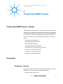
A Typical SerialBERT Program
A Typical Serial BERT Program - Concepts
Prerequisites 13
Prerequisites - Concepts
13
13
Initializing the Connection to the SerialBERT 14
Initializing the Connection - Concepts 14
Initializing the Connection - Procedures 14
Working with the IVI-COM Objects 15
Working with the IVI-COM Objects - Concepts 15
Working with the IVI-COM Objects - Procedures 15
Changing Instrument Parameters 16
Changing Instrument Parameters - Procedures
3
16
Recommended Programming Techniques
Recommended Programming Techniques - Concepts
19
Output Protection 19
Output Protection 19
Speed DUT Switching 20
Controlling the Output Levels 21
Controlling the Output Levels - Concepts 21
Controlling the Output Levels - Procedures 21
Agilent J-BERT N4903B High-Performance Serial BERT
3
Allowing the Serial BERT to Settle 22
Allowing Serial BERT to Settle - Concepts 22
Allowing Serial BERT to Settle - Procedures 22
Reading the Serial BERT's Status 24
Reading the Serial BERT's Status - Concepts 24
Reading the Serial BERT's Status - Procedures 27
Reading the Serial BERT's Status - Reference 27
Running the Fast Eye Mask 35
Running the Fast Eye Mask - Concepts 35
Running the Fast Eye Mask - Procedures 36
Running the Eye Diagram 38
Running the Eye Diagram - Concepts 38
Running the Eye Diagram - Procedures 39
Running JTol Characterization 39
Running JTol Characterization - Concepts 39
Running JTol Characterization - Procedures 40
Using Error Location Capture 42
Using Error Location Capture - Concepts 42
Using Error Location Capture - Procedures 46
Using Interrupts 52
Using Interrupts - Concepts 52
Using Interrupts - Procedures 53
Working With User Patterns 55
Working With User Patterns - Concepts 55
Working With User Patterns - Procedures 60
Working with 8B/10B Symbols 70
Working with 8B/10B Symbols – Concepts 70
Working with 8B/10B Symbols – Procedures 70
Working with PCIe3 SKPOS 75
Working with PCIe 3.0 SKPOS – Concepts
Working with PCIe3 SKPOS – Procedures
4
75
76
SCPI Command Language
SCPI Command Language - Concepts
79
Important Points about SCPI 82
Important Points about SCPI - Concepts
82
Sending Commands to the SerialBERT 86
Sending Commands to the Serial BERT - Concepts
4
86
Agilent J-BERT N4903B High-Performance Serial BERT
5
SCPI Command Reference
Serial BERT Subsystems
89
IEEE Commands 91
IEEE Commands – Reference
91
SOURce[1] Subsystem 98
SOURce[1] Subsystem - Reference
98
OUTPut[1] Subsystem 133
OUTPut[1] Subsystem - Reference
133
SOURce9 Subsystem 160
SOURce9 Subsystem - Reference
160
SOURce2 Subsystem 165
SOURce2 Subsystem - Reference
165
OUTPut2 Subsystem 171
OUTPut2 Subsystem - Reference
171
SOURce3 Subsystem 173
SOURce3 Subsystem - Reference
173
SOURce5 Subsystem 183
SOURce5 Subsystem - Reference
183
OUTPut5 Subsystem 189
OUTPut[5] Subsystem - Reference
SENSe6 Subsystem 191
SENSe6 Subsystem - Reference
189
191
SOURce8 Subsystem 195
SOURce8 Subsystem - Reference
195
INPut[1] Subsystem 220
INPut[1] Subsystem - Reference
220
SENSe[1] Subsystem 224
SENSe[1] Subsystem - Reference
INPut2 Subsystem 270
INPut2 Subsystem - Reference
SENSe2 Subsystem 271
SENSe2 Subsystem - Reference
224
270
271
SOURce7 Subsystem 279
SOURce7 Subsystem - Reference
279
[P]FETCh Subsystem 281
[P]FETCh Subsystem - Reference
281
Agilent J-BERT N4903B High-Performance Serial BERT
5
PLUGin Subsystem 312
PLUGin Subsystem - Reference
312
STATus Subsystem 316
STATus Subsystem - Reference
316
SYSTem Subsystem 330
SYSTem Subsystem - Reference
330
MEASure Subsystem 338
MEASure Subsystem - Reference
TEST Subsystem 402
TEST Subsystem - Reference
Index
6
338
402
405
Agilent J-BERT N4903B High-Performance Serial BERT
S
Agilent J-BERT N4903B High-Performance Serial BERT
Programming Guide
1
Programming Basics
Programming Basics - Concepts
This document provides the information you need for programming the Serial
BERT using the Agilent IO Libraries Suite. Familiarity with the Agilent IO Libraries
Suite is instrumental in understanding remote programming of the Serial BERT.
See the user documentation delivered with the Agilent IO Libraries Suite for
information on how to use them.
NOTE
CAUTION
Depending on the options of your Serial BERT, some of the following functions may
not be valid for your instrument. See the online Help or the User's Guide for a
description of the available options.
The following pattern generator ports must be terminated with 50 Ω if they are not
connected:
•
Data Out
•
Data Out
•
Clock Out
•
Clock Out
•
Aux Data Out
•
Aux Data Out
•
Trigger/Ref Clock Out
•
Trigger/Ref Clock Out
s Agilent Technologies
7
1 Programming Basics
Before You Begin
Before You Begin - Concepts
This section provides background information that you need before you start with
remote programming. It contains the following subjects:
•
“Communication Overview” on page 8
•
“Connecting to the Serial BERT” on page 9
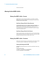
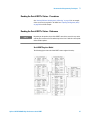
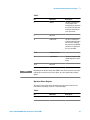
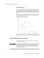
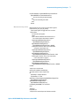
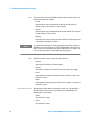
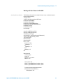
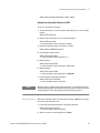
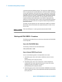
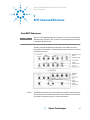
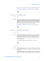
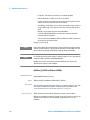
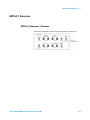
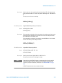
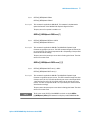
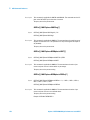
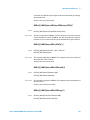
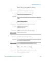
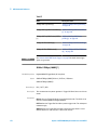
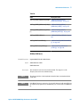
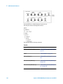
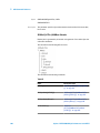
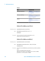
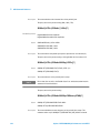
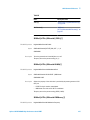
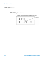
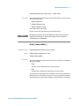
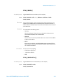
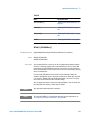
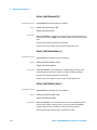
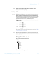
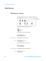
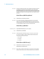
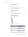
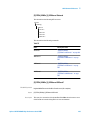
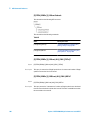
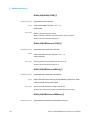
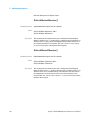
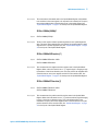
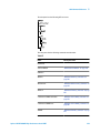
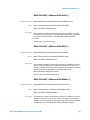
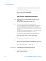
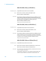
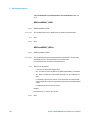
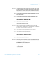
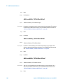
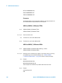
Communication Overview
Communication with the Serial BERT is based on a host-client protocol. The server
is the Serial BERT itself, the host is the remote client. The host requests the server
to carry out specific actions; the Serial BERT carries out the actions and returns
the results (if a query was sent).
Remote Host
jBERT
LAN|GPIB|USB
IVI-COM|SCPI
Agilent
Auto
Align
Pattern
Setup
PG/ED
Setup
Pattern Generator
AUX
IN
ERROR
ADD
CLK
IN
OUT
TRIGGER
OUT
OUT
SUB CLK
OUT
OUT
Jitter
Analysis
Results
CLK
OUT
OUT
Error Detector
DATA
OUT
P1
P1
DELAY
CTRL IN
P2
P2
ERR OUT TRIG OUT CLK IN
N4903A #J20
Error Detector
Pattern Generator
Data
Amplitude
Figure 1
Data
Offset
Data Out
Delay
Clock
Amplitude
Clock
Offset
Decision
Threshold
DATA
AUX OUT
IN
IN
GATE IN
Data In
Delay
Serial BERT Remote Communication
The Serial BERT uses either a SCPI interface or an IVI-COM interface for
communicating with the outside world. See “A Typical Serial BERT Program Concepts” on page 13 for information on getting started with remote
programming for the Serial BERT.
Depending on the options, your Serial BERT may come with a set of features for
advanced measurements (such as the DUT Output measurement). These advanced
measurements can only be accessed over the LAN interface. See the Measurement
Software Programming Guide for more information on programming the
measurements. In the online Help you find a description of the available options.
8
Agilent J-BERT N4903B High-Performance Serial BERT
Programming Basics
1
Connecting to the Serial BERT
To communicate with the Serial BERT from a remote computer, the Agilent IO
Libraries Suite must be installed on this computer.
NOTE
The following descriptions only provide you with the information you need from the
Serial BERT. For complete instructions on how to establish connections to the Serial
BERT, refer to the user documentation delivered with the Agilent IO Libraries Suite.
The Agilent IO Libraries Suite offers the following possibilities for remotely
connecting to and controlling the Serial BERT:
LAN
The Serial BERT's network settings are managed by the operating system. You can
use the IPCONFIG command in the command window to get the network settings.
The steps for setting up the network connection are OS-dependent (Serial
BERT's OS is Windows XP). Contact your network administrator if you need help
in defining the network settings.
GPIB
To connect to the Serial BERT via GPIB, you have to have the Serial BERT's GPIB
address.
The address is displayed on the user interface. The default address is 14. See the
online Help for details on how to set the GPIB address.
When setting the GPIB address, it is recommended that you do not use the GPIB
address 21. This address is reserved for GPIB controllers.
NOTE
USB
The Serial BERT has a USB port on the rear of the instrument that you can use to
connect it to a PC. This is the non-flat USB port below the GPIB port.
To connect to the Serial BERT via USB, you need the Serial BERT's USB ID. You
can either use the full VISA resource string or assign an alias. See the Agilent IO
Libraries Suite documentation for details.
Agilent J-BERT N4903B High-Performance Serial BERT
9
1 Programming Basics
Instrument Behavior
Instrument Behavior - Reference
The Serial BERT behaves as follows when it is turned on (or after a power-cycle):
Instrument Mode At power on, the Serial BERT will return to the same mode as it was powered down.
Normally, once it has booted, the Serial BERT is ready for either front panel
operation or remote operation.
Registers and Filters At power-on, the state of the registers and filters is:
•
Normal operation
The initial state of the registers and transition filters will be saved in the event
of a power failure.
•
Initial power-on
All registers and filters are disabled except the PON, CME and EXE bits of the
Standard Event Status Register and its summary bit in the Status Byte.
The transition filters will be set to allow all conditions and events to pass.
The event registers and the error queue are cleared at each and every power-up.
Overheat Protection
The Serial BERT protects itself from damage by overheating by shutting itself down
in such cases.
If the temperature of the pattern generator or error detector generator exceeds a
certain threshold, the OVERHEAT bit in the Operation register is set.
There are two thresholds: caution and warning. These both set the same bit: you
cannot programmatically get the threshold.
The caution threshold is not critical. You have enough time to save your current
settings and gracefully shut down the instrument.
The warning threshold is critical. If this threshold is reached, the instrument will
immediately shut itself down.
Overtemperature can be programmatically detected by querying the Status byte
(*STB). In case of overheating by either the error detector or pattern generator, the
Operation bit (bit 7) in the Status byte will be high, as will the OVERHEAT bit in the
Operation register. See “How the Serial BERT Uses Status Registers” on page
25 for details on reading the status registers.
10
Agilent J-BERT N4903B High-Performance Serial BERT
1
Programming Basics
You can identify whether the error detector or pattern generator is overheating by
running a self-test on both devices. To run a self-test:
See also the Serial BERT User Guide (or online Help) for details.
Operation Modes
The Serial BERT can be operated in one of two modes: local or remote.
Local Mode In local mode, all the front panel controls are responsive and control the instrument.
Remote Mode In remote mode, the front panel controls are inoperative and the instrument is
controlled by the client. The front panel display reflects the remote programming
commands received.
The Serial BERT automatically enters remote mode when a command has been
received from the client. This is indicated at the top of the front panel (the RMT
status light).
Returning to Local Mode To return to local mode, press the front panel Local key. When you power-cycle
the instrument, it will also start in local mode.
Agilent J-BERT N4903B High-Performance Serial BERT
11
1 Programming Basics
12
Agilent J-BERT N4903B High-Performance Serial BERT
S
Agilent J-BERT N4903B High-Performance Serial BERT
Programming Guide
2
A Typical SerialBERT Program
A Typical Serial BERT Program - Concepts
The Serial BERT can be controlled by a remote program using the IVI-COM driver.
The sections of this Help provide you with information you can use to quickly get
started with your first program. The examples here are written for Visual Basic 6.0,
but can also be ported to any programming language supported by IVI-COM.
You can use the following links to find Agilent's IVI-COM help resources in the
internet:
•
ADN Introducing IVI-COM Drivers:
www.agilent.com/find/adnivicominfo
•
ADN IVI-COM Briefs and Papers:
www.agilent.com/find/adnivicompapers
•
ADN IVI-COM Drivers and Components Downloads:
www.agilent.com/find/adnivicomdrivers
•
ADN Drivers and Software Downloads:
www.agilent.com/find/adndownloads
Prerequisites
Prerequisites - Concepts
Before you can control a Serial BERT remotely, the client computer (your PC, the
Serial BERT is the host) must meet the following prerequisites:
•
Agilent IO Libraries Suite installed
s Agilent Technologies
13
2 A Typical SerialBERT Program
•
IVI-COM driver installed
•
Configured IO connection to the Serial BERT (you should be able to find the
Serial BERT with the I/O libraries VISA assistant)
Initializing the Connection to the SerialBERT
Initializing the Connection - Concepts
The first step in setting up a program for controlling the Serial BERT is to create
an object that corresponds to the instrument. You can either use the Serial BERT
class (AgilentN490x), or you can use the IVI-compliant Agilent BERT class
(AgilentBert).
TIP
If you set up your code using the AgilentBert class, you can easily port your programs
to other IVI-compliant Agilent instruments. As Agilent's fulfillment of the IVIcompliance requirements, this class is shared by all other Agilent IVI-compliant
instruments.
The examples in this document show how to set up a reference to the AgilentBert
class and use this class.
Initializing the Connection - Procedures
The following code shows you how you would establish the connection to the
instrument. The ResourceName ("TCPIP1::10.0.0.207::inst0::INSTR") must be replaced
by the instrument's address string from the VISA Assistant.
' First our declarations...
Private myN490X As AgilentN490x
Private myBERT As AgilentBert
Private myPG As AgilentBertLib.IAgilentBertPG
Private myPGClock As AgilentBertLib.IAgilentBertPGClock
Private myPGOut As AgilentBertLib.IAgilentBertPGOutput
Private myEDDataIn As AgilentBertLib.IAgilentBertEDDataIn
Private Sub Form_Load()
Set myN490X = New AgilentN490x
Set myBERT = myN490x.IAgilentBert
myBERT.Initialize ("TCPIP1::10.0.0.207::inst0::INSTR",
14
Agilent J-BERT N4903B High-Performance Serial BERT
A Typical SerialBERT Program
2
True, True,"QueryInstrStatus=true")
End Sub
Private Sub Form_Unload(Cancel As Integer)
myBERT.Close
End Sub
Working with the IVI-COM Objects
Working with the IVI-COM Objects - Concepts
The Serial BERT IVI-COM driver uses a hierarchical class structure that follows the
build up of the instrument. For example, the instrument itself is represented by the
class AgilentN490x. The pattern generator is represented by the class
IAgilentN490xPG.
To access the instrument's pattern generator, you have to first access the object,
then the object's pattern generator collection, and finally the actual pattern
generator.
The items in the collections are accessed by the name. The easiest way to get the
name (if you do not know it) is through the collection's Name property.
Working with the IVI-COM Objects - Procedures
The following example shows you how to set up different objects for controlling
the Serial BERT. These objects are used in the following examples.
Private Sub InitializeObjects()
' TIP: Call this sub from the Form_Load sub.
Dim EDName as String
With myBERT
' Get the pattern generator using the naming conventions
Set myPG = .PGs.Item("PG1")
' Use the myPG object to get sub-items
Set myPGClock = myPG.Clock
Set myPGOut = myPG.Outputs.Item("PGOutput1")
' Get the error detector by catching and using its name:
EDName =.EDs.Name(1)
Agilent J-BERT N4903B High-Performance Serial BERT
15
2 A Typical SerialBERT Program
Set myED = .EDs.Item(EDName)
Set myEDDataIn = myED.Input.DataIns.Item("EDDataIn1")
End With
End Sub
Changing Instrument Parameters
Changing Instrument Parameters - Procedures
The following examples show you how to:
•
Change the pattern generator's clock rate and voltagesƒ
•
Trigger auto-synchronization
•
Set up a pattern
Changing the Pattern Generator's Clock Rate and Output Voltages
The following code sets the pattern generator's clock frequency and toggles as
example the offset voltage between 0 and 0.5 Volts.
Private Sub SetUpPG
' Set the clock frequency
myPGClock.Frequency = 3 * 10 ^ 9
' Toggle the offset voltage (for demo purposes)
If myPGOut.OutVoltage.VOffset = 0 Then
myPGOut.OutVoltage.VOffset = 0.5
Else
myPGOut.OutVoltage.VOffset = 0
End If
End Sub
Analyzer Synchronization
The following code causes the error detector to synchronize.
Private Sub RunSync()
' First run the synchronization
myEDDataIn.Sampling.AutoAlign
' And then align the data
16
Agilent J-BERT N4903B High-Performance Serial BERT
A Typical SerialBERT Program
2
myEDDataIn.Synchronisation.SyncNow
End Sub
Setting Up a Pattern
The following code shows you how to set up a pattern. It additionally shows a
small function that converts strings into arrays that Visual Basic can handle.
Private Sub SetUpPattern()
Dim myPattern As AgilentBertLib.IAgilentBertLocalPatternfile
' Use local pattern 13 to save the pattern files
' to a different location
Set myPattern = myBERT.LocalPatternfiles._
Item(myBERT.LocalPatternfiles.Name(13))
With myPattern
' Set the length and description
.Length = 8
.Description = "Test pattern"
' Define the pattern to be alternate, set the data
' For VB, we have to convert the data to an array of doubles
' See function below for details
.Alternate = True
.SetData 1, AgilentLocalPatternFormatBin, _
SetPatternData("00001111", AgilentLocalPatternFormatBin)
.SetData 2, AgilentLocalPatternFormatBin,
SetPatternData("11111111", AgilentLocalPatternFormatBin)
End With
' And now load the pattern to the pattern generator
myPGOut.SelectData AgilentN490xPGOutputSelectFile, _
myPattern.Location
' And to the error detector
myEDDataIn.SelectData AgilentBertEDDataInSelectFile, _
myPattern.Location
End Sub
Private Function SetPatternData(DataString As String, _
Format As AgilentBertLib.AgilentBertEDPatternFormatEnum)
Dim myPattern() As Double
Dim ix As Integer
ReDim myPattern(Len(DataString) - 1)
For ix = 1 To Len(DataString)
Select Case Format
' How to interpret the string depends on the format
Case AgilentBertEDPatternFormatBin
myPattern(ix - 1) = CByte(Mid(DataString, ix, 1))
Case AgilentBertEDPatternFormatHex
Agilent J-BERT N4903B High-Performance Serial BERT
17
2 A Typical SerialBERT Program
myPattern(ix - 1) = CByte("&H" & Mid(DataString, ix, 1))
Case AgilentBertEDPatternFormatRaw
myPattern(ix - 1) = CByte(Mid(DataString, ix, 1))
End Select
Next
SetPatternData = myPattern
End Function
18
Agilent J-BERT N4903B High-Performance Serial BERT
S
Agilent J-BERT N4903B High-Performance Serial BERT
Programming Guide
3
Recommended Programming
Techniques
Recommended Programming Techniques - Concepts
This chapter provides some recommended techniques you should use when
programming the Serial BERT.
Output Protection
Output Protection
The pattern generator's Data, Clock, Aux Data and Trigger/Ref Clock Out ports
must be terminated with 50 Ω if they are not connected. Termination of output
ports improves the test performance.
The following sections describe a protection algorithm and how you can handle
the algorithm's delay time in an automated test environment.
Output Protection Algorithm
The instrument has an internal protection algorithm that protects the instrument
from improper termination of the pattern generator's output ports.
The algorithm checks for an open condition on these ports every 100ms. If the ports
are not correctly terminated, the algorithm adjusts the port's output levels to safe
levels:
•
VTerm remains unchanged.
s Agilent Technologies
19
3 Recommended Programming Techniques
•
VHigh = VTerm + 1 V
•
VLow = VTerm + 0.9 V
If the port is correctly terminated while in this state, the output levels are returned
to the original levels.
NOTE
If VTerm is greater than 1.5V, the protection algorithm is not active.
In an automated test environment, the algorithm may introduce up to 200ms delay
time when switching the DUT. You can avoid the protection algorithm from
becoming active when switching the DUT (and thus enhance the test throughput).
Speed DUT Switching
At the end of a test when the DUT is ready to be changed, proceed as follows:
1 If VTerm < +1.5V, adjust a high level that is less than 1V below VTerm (VHigh <
VTerm + 1V). This prevents the protection algorithm from becoming active.
For example, if VTerm = 1.0V, you have to make sure that the high level is 2.0V
or less. The following command shows how you set the high level of the Data
Out port to 1.25 V:
SOURce1:VOLTage:HIGH 1.25
If the termination voltage is higher than +1.5V, no voltage levels need to be
adjusted (the algorithm is not active).
2 Remove the tested DUT and connect the next DUT.
3 Restore both high level and low level.
4 Start testing the new DUT.
NOTE
20
Make sure that all Data Out and Clock Out ports are terminated. If not, the protection
algorithm may become active.
Agilent J-BERT N4903B High-Performance Serial BERT
3
Recommended Programming Techniques
Controlling the Output Levels
Controlling the Output Levels - Concepts
When the output levels are changed at the Serial BERT's data and clock output
ports, four parameters are changed:
•
Vhi
•
Vlo
•
Vampt
•
Voffs
The Serial BERT groups these parameters into "pairs" (Vampt/Voffs, Vhi/Vlo). If one
of these values is modified, its "partner" remains constant, and the values in the
other pair are modified accordingly. For example, if Vampt is changed, Voffs stays
constant, and Vhi and Vlo are modified accordingly.
Controlling the Output Levels - Procedures
Changing the Voltages with IVI- The IVI-COM driver provides a convenient function for setting Vampt and
COM Voffs :Configure. To set the pattern generator's data output voltage:
Private Sub SetPGDataOutVolt()
Dim myPG As AgilentN490xLib.IAgilentN490xPG
Dim myPGOut As AgilentN490xLib.IAgilentN490xPGOutput
Set myPG = myBERT.PGs.Item("PG1")
Set myPGOut = myPG.Outputs.Item("PGOutput1")
myPGOut.OutVoltage.Configure 1.5, 0.5, _
myPGOut.OutVoltage.VTermination
End Sub
Changing the Voltages with SCPI The following command shows how you would set the data output so that it has
an amplitude of 1.5V and an offset of 0.5 V :
SOUR:VOLT:AMPL 1.5; OFFS 0.5
This sets the output accordingly (VHi = 1.25 V, VLo = -0.25).
Conversely, you could set VHi and VLo directly:
SOUR:VOLT:HIGH 1.25; LOW -0.25
Agilent J-BERT N4903B High-Performance Serial BERT
21
3 Recommended Programming Techniques
This has the same effect.
Allowing the Serial BERT to Settle
Allowing Serial BERT to Settle - Concepts
When patterns are sent to the pattern generator or error detector, the Serial
BERT requires some time to settle before. The following topics explain how the
instruments react to pattern changes.
How Pattern Changes Affect the Pattern Generator
The Serial BERT requires some time to change the patterns at the pattern
generator and error detector. This is particularly true for large text-based (ASCII)
patterns that have to be loaded from the file system. In such a case, it is a
recommended technique to always query the Serial BERT's Operation Complete
status after changing the pattern.
How Pattern Changes Affect the Error Detector
When the pattern changes, the error detector has to resync to the new incoming
signal. Depending on the signal, the alignment method used, and the desired BER
threshold, this procedure can take up to half a minute or more.
Allowing Serial BERT to Settle - Procedures
When patterns have been changed, you should check the status registers to make
sure that the operation is complete before continuing with your program.
Checking the Settling with IVI-COM
The following example illustrates how to check the synchronization status using
IVI-COM.
Private Sub CheckSyncStatus()
Dim BERTStatus As AgilentN490x.Interop.IAgilentN490xStatus
Dim myED As AgilentN490x.Interop.IAgilentN490xED2
22
Agilent J-BERT N4903B High-Performance Serial BERT
Recommended Programming Techniques
3
Dim myPG As AgilentN490x.Interop.IAgilentN490xPG2
Set BERTStatus = myBERT.Status
Set myED = myBERT.EDs.Item("ED1")
Set myPG = myBERT.PGs.Item("PG1")
' First enable the register of interest:
' Operation register, bit 13, positive transition
BERTStatus.Register(AgilentN490xStatusRegisterOperation, _
AgilentN490xStatusSubRegisterEnable) = &H2000
BERTStatus.Register(AgilentN490xStatusRegisterOperation, _
AgilentN490xStatusSubRegisterPositiveTransition) = &H0
BERTStatus.Register(AgilentN490xStatusRegisterOperation, _
AgilentN490xStatusSubRegisterNegativeTransition) = &H2000
' Now clear the registers
BERTStatus.Clear
' ED should track the PG
myED.Input.DataIns.Item("EDDataIn1").TrackingEnabled = True
' Load the pattern
myPG.Outputs.Item("PGOutput1").SelectData
AgilentN490xPGOutputSelectFile, "testptr.ptrn"
' Just wait until the Operation bit goes low
Do While (BERTStatus.SerialPoll And &H80)
DoEvents
Loop
End Sub
Checking the Analyzer Sync with SCPI Using Agilent I/O Libraries
The following example illustrates how to check the synchronization status using
SCPI.
/* We need to check sync loss bit
of the Questionable register (bit 10) */
const unsigned int QUESTION_REG_10 = 2^10;
unsigned int question_reg;
unsigned int opc_stat;
/* Make sure the error detector tracks
the pattern generator */
viPrintf(vi, "SENSe1:PATTern:TRACk ON\n");
/* Load a pattern file to the instruments */
viPrintf(vi, "SOURce1:PATTern:SELect FILename, testfile.ptrn\n");
/* Wait until the instrument is in operational state */
viQueryf(vi, "*OPC?\n", "%d", &opc_stat);
do
{
/* Get the Questionable register */
viQueryf (vi, "STATus:QUEStionable:CONDition?\n", "%d",
&question_reg);
/* Loop until the sync loss bit goes low */
Agilent J-BERT N4903B High-Performance Serial BERT
23
3 Recommended Programming Techniques
}
while(question_reg() && QUESTION_REG_10);
If Question_reg returns a value that includes bit 10 ("1024"), this is an indication that
the error detector has not yet synchronized to the new pattern. In this case, the
instrument has not yet settled.
NOTE
File accessing, especially for large files can take some time. Control programs must
be prepared for time-outs of this size.
Reading the Serial BERT's Status
Reading the Serial BERT's Status - Concepts
The Serial BERT has a set of status registers that you can use to monitor the status
of the hardware, software, and any running tests.
Overview of Registers Specifically, it has the following registers:
•
Status Byte
The Status Byte is a single register that stores the events occurring on the
other registers.
•
Standard Event Status Register
The Standard Event Status Register monitors some non-critical errors and basic
operations.
•
Questionable Data Status Register
The bits in the Questionable Data Status Register are set when certain events
occur in the Serial BERT that can lead to questionable results.
•
Operation Status Register
The Operation Status Register indicates when certain operations have been
completed.
•
Clock Loss Status Register
The Clock Loss Status Register indicates if the Serial BERT's pattern generator
or error detector have lost the clock signal.
24
Agilent J-BERT N4903B High-Performance Serial BERT
3
Recommended Programming Techniques
How the Serial BERT Uses Status Registers
You can determine the state of certain instrument hardware and firmware events
and conditions by programming the status register system.
The following subsections provide you with details about the Serial BERT's status
system.
Overview of the Serial BERT's Status System
The Serial BERT has status reporting features that give important information about
events and conditions within the instrument. For example, a flag may be set to
indicate the end of a measurement or perhaps a command error. To access this
information, it is necessary to query a set of registers using SCPI.
Serial BERT's Status System Structure
The Serial BERT's status system is comprised of multiple registers that are
arranged in a hierarchical order. The lower-level status registers propagate their
data to the higher-level registers in the data structures by means of summary bits.
The Status Byte register is at the top of the hierarchy and contains general status
information for the Serial BERT's events and conditions. All other individual
registers are used to determine the specific events or conditions.
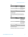
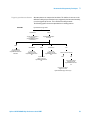
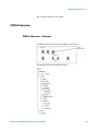
For figures showing Serial BERT's status registers, see “Serial BERT Register
Model” on page 27.
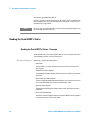
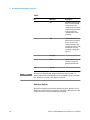
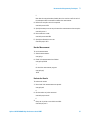
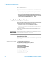
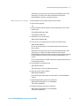
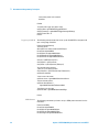
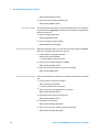
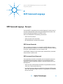
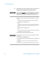
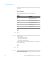
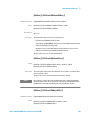
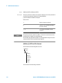
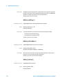
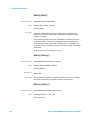
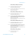
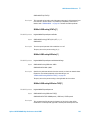
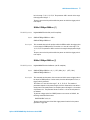
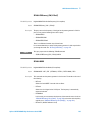
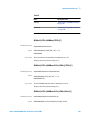
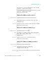
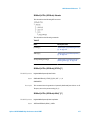
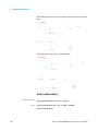
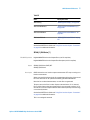
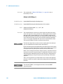
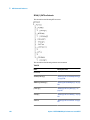
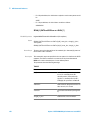
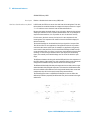
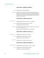
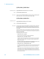
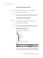
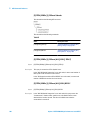
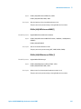
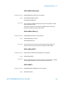
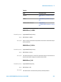
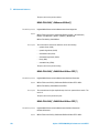
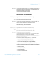
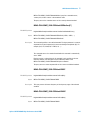
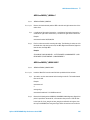
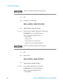
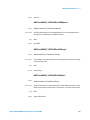
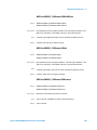
Status Register Group Model
The following figure illustrates the typical structure of a status register.
Condition
Register
Bit 0
Bit 1
...
Bit 15
Transition
Filter
PTRans
NTRans
PTRans
NTRans
Event
Register
Event Enable
Register
Bit 0
Bit 0
Bit 1
Bit 1
...
...
...
Bit 15
Bit 15
PTRans
NTRans
As shown in this figure, most status registers actually consist of five registers:
•
Condition
Agilent J-BERT N4903B High-Performance Serial BERT
25
3 Recommended Programming Techniques
The condition register continuously monitors the hardware and firmware status
of the instrument. There is no latching or buffering for a condition register. It
is updated in real time.
This register is read by the CONDition? SCPI commands.
•
Negative Transition
The negative transition register specifies the bits in the condition register that
will set corresponding bits in the event register when the condition bit changes
from 1 to 0.
This register is set and read by the NTRAnsition[?] SCPI commands.
•
Positive Transition
A positive transition register specifies the bits in the condition register that will
set corresponding bits in the event register when the condition bit changes
from 0 to 1.
•
Event
An event register latches transition events from the condition register as
specified by the positive and negative transition filters. Bits in the event register
are latched, and once set, they remain set until cleared by either querying the
register contents or sending the *CLS command.
•
Event Enable
An enable register specifies the bits in the event register that can generate a
summary bit. Summary bits are, in turn, used by the next higher register.
The registers work together as follows:
1 The Condition Register corresponds to a condition on the hardware or in the
software. If the monitored condition is present, the corresponding bit is high.
2 The Transition Registers monitor changes in the Condition Register. If the
Positive Transition Register is configured to watch for a condition, when this
condition occurs, and the bit in the Condition Register goes high, the Positive
Transition Register passes this event to the Event Register.
3 If this bit is enabled in the Enable Event Register, a summary bit is generated
in the next higher register. For the higher register, this is the Condition Register,
and the event is handled the same way as described here.
NOTE
26
The transition and enable registers for the Failure Status register (and its
subregisters) cannot be modified.
Agilent J-BERT N4903B High-Performance Serial BERT
Recommended Programming Techniques
3
Reading the Serial BERT's Status - Procedures
See “Starting ELOC and Verifying that it is Running” on page 47 for an example
of how to access the registers in IVI-COM. See “Preparing the Registers (SCPI)”
on page 50 for a SCPI example.
Reading the Serial BERT's Status - Reference
NOTE
Depending on the options of your Serial BERT, some of the status bits may not be
valid for your instrument. See the online Help or the User's Guide for a description
of the available options.
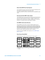
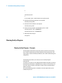
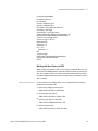
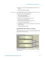
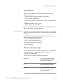
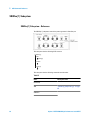
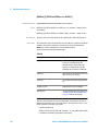
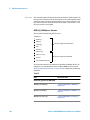
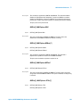
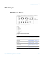
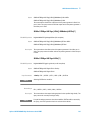
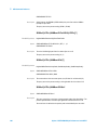
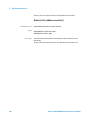
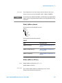
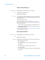
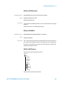
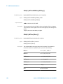
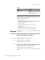
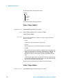
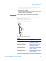
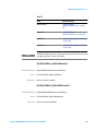
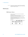
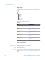
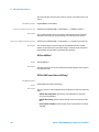
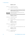
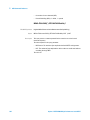
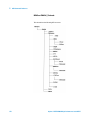
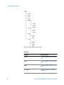
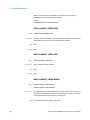
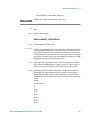
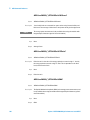
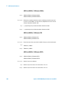
Serial BERT Register Model
The following figure shows the Serial BERT's status register hierarchy.
Agilent J-BERT N4903B High-Performance Serial BERT
27
3 Recommended Programming Techniques
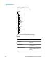
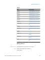
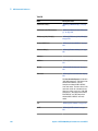
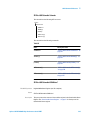
Status Byte
The Status Byte is the summary register to which the other registers report. Each
reporting register is assigned a bit in the Status Byte Register.
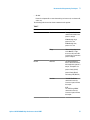
The bits in the Status Byte byte have the following meaning:
Table 1
Bit 6
Bit
Mnemonic
Description
0
Not used
1
Not used
2
EAV
Error available: The error
queue contains at least
one message.
3
QUES
A bit has been set in the
Questionable Data Status
register (indicates that a
signal is of questionable
quality).
4
MAV
Message available: There
is at least one message in
the message queue.
5
ESB
A bit in the Standard Event
Register has been set.
6
SRQ or MSS
Value depends on the
polling method; see below
for details.
7
OPER
A bit in the Operation
Status Register has been
set.
Bit 6 has two definitions, depending on how the access is polled:
•
Serial Poll
If the value of the register is read using the serial poll (SPOLL), bit 6 is referred
to as the Service Request (SRQ) Bit. It is used to interrupt and inform the active
controller that the instrument has set the service request control line, SRQ.
28
Agilent J-BERT N4903B High-Performance Serial BERT
3
Recommended Programming Techniques
•
*STB?
If the register is read using the common command *STB? , bit 6 is referred to
as the master summary bit or MSS bit. This bit indicates that the instrument
has requested service. The MSS bit is not cleared when the register is read
using the *STB? command. It always reflects the current status of all the
instrument's status registers.
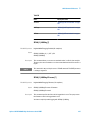
Standard Event Status Register
The Standard Event Status register is a 16-bit register group that gives generalpurpose information about the instrument. It sets bit 5 in the Status Byte.
Table 2
Bit
Mnemonic
Description
0
OPC
Operation Complete bit. It
is set in response to the
*OPC command, but only if
the instrument has
completed all its pending
operations.
1
Not used
2
QYE
Query error bit. It indicates
that there is a problem
with the output data
queue. There has been an
attempt to read the queue
when it is empty, the
output data has been lost,
or the query command has
been interrupted.
3
DDE
Device-dependent error
bit. It is set when an
instrument-specific error
has occurred.
Agilent J-BERT N4903B High-Performance Serial BERT
29
3 Recommended Programming Techniques
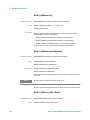
Table 2
NOTE
Bit
Mnemonic
Description
4
EXE
Execution error bit. It is set
when a command (GPIB
instrument specific)
cannot be executed due to
an out of range parameter
or some instrument
condition that prevents
execution.
5
CME
Command error bit. It is set
whenever the instrument
detects an error in the
format or content of the
program message (usually
a bad header, missing
argument, or wrong data
type etc.).
6
Not used
7
PON
8-15
Not used
Power-on bit. It is set each
time the instrument is
powered from off to on.
This register is compatible with the generalized status register model. It is
comprised of an event and enable register, but no condition register or transition
filter. All positive transitions in this register are latched.
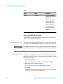
Clock Loss Register
The Clock Loss Register group indicates whether the pattern generator or error
detector has experienced a clock signal loss. The output of this register sets bits
5 and 9 (Clock Loss) in the Questionable Status Register.
30
Agilent J-BERT N4903B High-Performance Serial BERT
Recommended Programming Techniques
3
Table 3
Bit
Mnemonic
Description
0
ERR DET
Clock loss condition at the
error detector.
1
PAT GEN
Clock loss condition at the
pattern generator.
2-15
Not used
Symbol Mode Register
The Symbol Mode Register group indicates whether the error detector has
experienced a 10B symbol alignment loss or 10B symbol alignment done. The
output of this register sets bit 12 (Symbol Mode) in the Questionable Status
Register.
Table 4
Bit
Mnemonic
Description
0
SYMB ALIGN LOSS
10B symbol alignment loss
condition at the error
detector. The Symb Lock
indicator turns red.
1
SYMB ALIGN DONE
10B symbol alignment
done condition at the error
detector. The Symb Lock
indicator turns green.
2-15
Not used
Questionable Status Register
The Questionable Status Register indicates that a currently running process is of
questionable quality. The output of this register sets bit 3 of the Status Byte.
Agilent J-BERT N4903B High-Performance Serial BERT
31
3 Recommended Programming Techniques
Table 5
32
Bit
Mnemonic
Description
0
DATA LOSS
This bit is set when the
data source is turned off,
not connected, or the
cables or device is faulty.
This bit can also set when
the 0/1 threshold is not in
the eye limits of the
incoming data signal. In
this last case, use Auto
Align or select Avg 0/1
Threshold.
1-4
Not used
5
CLOCK LOSS
This bit is set when the
pattern generator receives
no external clock signal or
the error detector receives
no clock input signal. To
find out which of the 2
events is causing this bit to
set, you must poll the
Clock Loss Status
Register; see “Clock Loss
Register” on page 30.
6
PROTECT ED DATA IN
This bit indicates that the
protection mechanism for
the Data Input port of the
error detector was
activated, e.g. the voltage
or current measured at this
port was out of range.
7
PROTECT PG DELAY CTRL This bit indicates that the
IN
protection mechanism for
the Delay Control Input
port of the pattern
generator was activated,
e.g. the voltage or current
measured at this port was
out of range.
Agilent J-BERT N4903B High-Performance Serial BERT
Recommended Programming Techniques
3
Table 5
NOTE
Bit
Mnemonic
Description
8
UNCAL
This bit is set when the
serial number of the
installed pattern generator
or error detector does not
match the calibration file
in the instrument.
9
Not used
10
SYNC LOSS
11-15
Protection Circuit
12
Symbol Mode
13-15
Not used
This bit is set when the
error detector pattern does
not match the incoming
data pattern or the BER of
your device is higher than
the sync threshold.
This bit is set when a 10B
symbol alignment is done
or lost.
Depending on the options of your Serial BERT, some of the status bits may not be
valid for your instrument. See the User Guide for a description of the available
options.
Operation Status Register
The output of this register gives information about the current operation the
instrument is performing. It sets bit 7 of the Status Byte.
Table 6
Bit
Mnemonic
0-2
Not used
Agilent J-BERT N4903B High-Performance Serial BERT
Description
33
3 Recommended Programming Techniques
Table 6
34
Bit
Mnemonic
Description
3
OVERHEAT
The pattern generator or
error detector has a
higher-than-normal
temperature.
4
GATE ON
An accumulated
measurement is in
progress.
5-6
Not used
7
GATE ABORT
Indicates that the
repetitive accumulation
period was aborted.
8
BIT ERR
The instrument has
detected a bit error.
9-10
Not used
11
CLK/DATA CTR
Indicates that the clock/
data alignment is in
progress.
12
DATA 0/1 THR ALIGN
Indicates that the 0/1
threshold alignment is in
progress.
13
AUTO ALIGN
Indicates that the auto
alignment is in progress.
14
ERR LOC CAPTURE
Indicates that there is an
Error Location Capture
measurement in progress.
15
Block Change
When a user-defined
sequence is generated:
Reports a transition from
one block to another.
Agilent J-BERT N4903B High-Performance Serial BERT
Recommended Programming Techniques
NOTE
3
Depending on the options of your Serial BERT, some of the status bits may not be
valid for your instrument. See the User Guide for a description of the available
options.
Running the Fast Eye Mask
Running the Fast Eye Mask - Concepts
NOTE
This topic is only valid for instruments with the Fast Eye Mask option. See the User
Guide for a description of the available options for your instrument.
The Fast Eye Mask measurement is first of all meant for production and screening
tests. It allows to determine very quickly whether the eye opening seen at the
output signal of a device is within specifications, that is, within certain timing and
voltage limits.
The following topics inform you on how you can programmatically set up Fast Eye
Mask measurements.
See the online Help or the User's Guide for details on working with the Fast Eye
Mask.
To be able to set up and run a Fast Eye Mask measurement using SCPI, you should
be aware that the Fast Eye Mask measurement is programmatically implemented
as an object on the instrument. You must first create an instance of the object, and
then use the handle returned to address this object.
As good programming practice, also be sure to close the object when you are
finished with your test.
Agilent J-BERT N4903B High-Performance Serial BERT
35
3 Recommended Programming Techniques
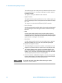
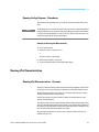
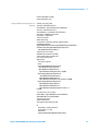
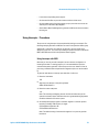
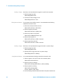
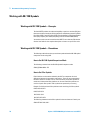
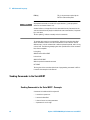
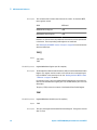
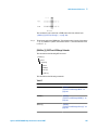
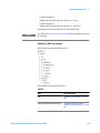
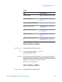
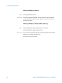
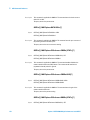
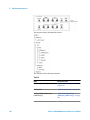
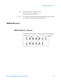
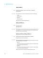
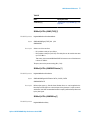
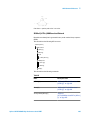
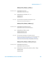
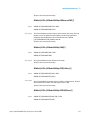
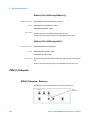
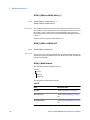
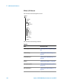
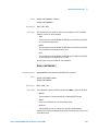
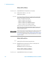
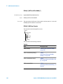
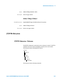
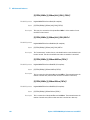
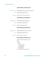
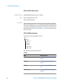
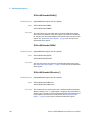
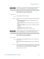
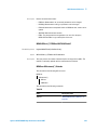
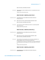
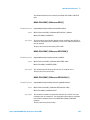
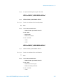
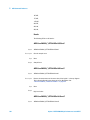
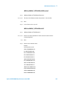
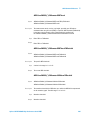
Setting Up Data Points
When you create a measurement object, the object is set up by default with six
symmetrically placed data points, as shown in the following figure:
These settings can be changed, and up to 32 measurement points can be defined.
For this, you would first change the number of measurement points, and then
specify each of the points as required.
Running the Fast Eye Mask - Procedures
The following code indicates how you could set up and run the Fast Eye Mask
using SCPI.
NOTE
The Fast Eye Mask measurement displayed in the user interface cannot be
controlled remotely. When you set up a program to run a Fast Eye Mask
measurement remotely, a separate measurement object is created. Any
programmatical changes to this measurement object will not be reflected in the
user interface.
Prepare the Measurement
To create the measurement object and prepare the measurement:
1 Create the session:
meas:fem:cre?
36
Agilent J-BERT N4903B High-Performance Serial BERT
Recommended Programming Techniques
3
2
Note that the returned number (handle) has to be used as a suffix in each of
the subsequent SCPI commands to address the measurement.
2 Define how many bits are to be compared:
meas:fem2:par:mcb 1.0E+6
3 Specify how many errors at one point move the measurement to the next point:
meas:fem2:par:merr 1
4 Now enable error mode:
meas:fem2:par:merr:mode ENA
5 Specify the allowed bit error rate:
meas:fem2:par:pfcr 1.0E-9
Run the Measurement
To run the measurement:
1 Start the measurement:
meas:gen2:go
2 Check if the measurement has finished:
meas:gen2:opc? BLOCk
1
Or check the measurement progress:
meas:gen2:prog?
1.0E+0
Evaluate the Results
To evaluate the results:
1 Now check if the measurement was passed:
meas:gen2:pass?
0
2 Get the number of points measured:
meas:fem2:par:point:numb?
6
3 Query the six points to see which one failed:
meas:fem2:poin:pass? 1
Agilent J-BERT N4903B High-Performance Serial BERT
37
3 Recommended Programming Techniques
0
...
meas:fem2:poin:pass? 6
0
In our example, points 1 and 6 failed, the other points passed.
4 Specify how the timing resolution is to be reported:
meas:fem2:par:tres:type UINT
5 Specify how the threshold is to be reported:
meas:fem2:par:thr:type ABS
6 Check the timing resolution and threshold at points 1 and 6:
meas:fem2:par:point? 1 -4.0E-1,1.525000035763E-1
meas:fem2:par:point? 6 1.6E-1,-4.749999642372E-2
7 And finally close the object:
meas:gen2:clos
Running the Eye Diagram
Running the Eye Diagram - Concepts
The Eye Diagram measurement is generally used for production and screening
tests. It helps in determining very quickly whether the eye opening seen at the
output signal of a device is within specifications, that is, within certain timing and
voltage limits.
The following topics inform you on how you can run the Eye Diagram
measurements.
To be able to set up and run an Eye Diagram measurement using SCPI, you should
know that this measurement is implemented as an object on the instrument. You
must first create an instance of the object, and then use the returned handle to
address this object.
As a good programming practice, remember to close the object when you are
finished with your test.
38
Agilent J-BERT N4903B High-Performance Serial BERT
3
Recommended Programming Techniques
Running the Eye Diagram - Procedures
The following code indicates how you could set up and run the Eye Mask using
SCPI.
NOTE
The Eye Diagram measurement displayed in the user interface cannot be controlled
remotely. When you set up a program to run an Eye Diagram measurement remotely,
a separate measurement object is created. The user interface does not reflect any
change in program for this measurement object.
Example to Running the Measurement
To run the measurement:
1 Create the session: :meas:emas(*):cre?
2
The return value 2 is the handle.
2 Start the measurement: meas:gen2:go
3 To get the measured data: :meas:emas2:fetc:data? 102017
Running JTol Characterization
Running JTol Characterization - Concepts
The Jitter Tolerance Characterization test determines the amplitude of jitter a data
receiving circuit can cope with before it produces an untolerable number of errors.
The following topics inform you on how you can programmatically set up Jitter
Tolerance Characterization measurements.
See the online Help or the User's Guide for details on working with the Jitter
Tolerance Characterization.
To be able to set up and run a Jitter Tolerance Characterization measurement using
SCPI, you should be aware that the measurement is programmatically implemented
as an object on the instrument. You must first create an instance of the object, and
then use the handle returned to address this object.
As good programming practice, also be sure to close the object when you are
finished with your test.
Agilent J-BERT N4903B High-Performance Serial BERT
39
3 Recommended Programming Techniques
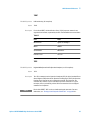
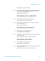
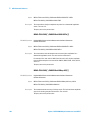
Setting Up Data Points
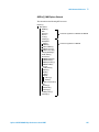
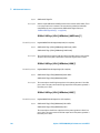
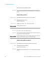
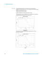
The Jitter Tolerance Characterization test generates jitter with varying amplitudes.
The condition for proceeding from one amplitude to the next and the direction
(upwards or downwards) can be specified, as well as the step size. The test for a
given frequency stops when the measured BER exceeds (or falls below) the target
BER.
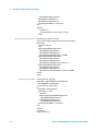
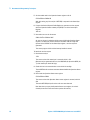
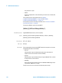
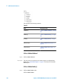
The test can be swept automatically over a wide frequency range. Test result is
the jitter tolerance curve of the device. This curve is constructed from the pass/
fail transitions of the measured points.
The following figure shows an example.
Besides the target bit error ratio, you need to specify the verification method and
the positioning of the measured points. The latter can be done in manifold ways.
Running JTol Characterization - Procedures
The following code indicates how you could set up and run the Jitter Tolerance
Characterization test using SCPI.
NOTE
40
The Jitter Tolerance Characterization measurement displayed in the user interface
cannot be controlled remotely. When you set up a program to run a Jitter Tolerance
Characterization measurement remotely, a separate measurement object is
created. Any programmatical changes to this measurement object will not be
reflected in the user interface.
Agilent J-BERT N4903B High-Performance Serial BERT
Recommended Programming Techniques
3
Prepare the Measurement
To create the measurement object and prepare the measurement:
1 Create the session:
meas:jtol:char:cre?
7
Note that the returned number (handle) has to be used as a suffix in each of
the subsequent SCPI commands to address the measurement.
2 Specify the target bit error ratio:
meas:jtol:char7:par:btes:tber 1.0E-12
3 Specify how the target BER shall be verified:
meas:jtol:char7:par:btes CLEV
4 For confidence mode (CLEVel), set the confidence level:
meas:jtol:char7:par:btes:clev 95E-2
5 Specify the frequencies to be measured. The following command creates a list
of 10 logarithmically equidistant steps between 10 kHz and 10 MHz:
meas:jtol:char7:par:flis:fill 1.0E+4, 1.0E+7, 10
6 Decide on the search method. The following establishes a downwards
logarithmic search:
meas:jtol:char7:par:sear DLOG
7 Set the stop value. This is the minimum jitter amplitude in UI:
meas:jtol:char7:par:sear:dlog:stop 1.0E-1
8 Set the ratio between two vertical amplitude steps:
meas:jtol:char7:par:sear:dlog:rati 6.6E-1
Run the Measurement
To run the measurement:
1 Start the measurement:
meas:gen7:go
2 Check if the measurement has finished:
meas:gen7:opc? BLOC
1
Or check the measurement progress:
meas:gen7:prog?
Agilent J-BERT N4903B High-Performance Serial BERT
41
3 Recommended Programming Techniques
1.0E+0
Evaluate the Results
To evaluate the results:
1 Get the number of points measured:
meas:jtol:char7:fetc:data:ava?
54
2 Ask for the DUT capability:
meas:jtol:char7:fetc:data:cap? DUT
This returns for each of the measured frequencies the maximum jitter amplitude
the DUT could stand without exceeding the target BER. These are the values
that form the jitter tolerance curve.
3 Query the measured points to inspect the results in detail:
meas:jtol:char7:fetc:data:poin? 54, 0
This returns the settings and results for the leftmost 54 points.
4 Finally close the object:
meas:gen7:clos
Using Error Location Capture
Using Error Location Capture - Concepts
What is Error Location Capture?
Error Location Capture allows to capture the position of an errored bit in a memorybased pattern. The instrument saves the position of the errored bit and writes a
bit sequence neighbouring the errored bit to a file.
This feature can be used to find rare or random errors. A DUT could have problems
handling long series of zeroes. Error Location Capture can be used to locate the
bit errors in such cases.
NOTE
42
Error Location Capture may not be available to all instruments or options. See the
online Help or the User's Guide for details on the available features of your
instrument.
Agilent J-BERT N4903B High-Performance Serial BERT
Recommended Programming Techniques
3
Restrictions for Error Location Capture
Error Location Capture is subject to the following restrictions:
•
Only memory-based patterns with a unique 48-bit pattern (detect word) are
allowed.
•
The error detector must be aligned to the incoming stream.
•
No alignment features can run during error location capture: Auto Align, 0/1
Threshold Center, Data Center
•
No other advanced measurement (Output Timing, Output Levels, etc.) can be
running.
•
Error Location Capture can only run when the BER Location Mode is set to
more than one bit (for example, all bits, or a block with a length > 1).
How to Run Error Location Capture
The following steps are recommended for running Error Location Capture:
1 Reset the instrument.
2 Load a pattern from the pattern folder to the Pattern Generator and to the Error
Detector.
3 Synchronize the Error Detector.
4 Clear the status registers.
5 Set up the Operation Status register so that it triggers when Error Location
Capture starts.
The Operation Status register should catch positive transitions on the ERR LOC
CAPTURE bit (bit 14).
6 Start the Error Location Capture. This is an overlapped command.
7 Set up a loop that queries the Operation Status register until the Error Location
bit goes high. This indicates that the Error Location Capture has started.
NOTE
Because Error Location Capture would run forever if no errors are detected, it is
recommended to also set up a time-out in your program.
How to See if Error Location Capture has Stopped
To see if Error Location Capture has stopped:
1 Set up the Operation Status register so that it triggers when Error Location
Capture stops.
Agilent J-BERT N4903B High-Performance Serial BERT
43
3 Recommended Programming Techniques
The Operation Status register should catch negative transitions on the ERR LOC
CAPTURE bit (bit 14).
2 Check the status registers to see if Error Location Capture has stopped.
3 If it has stopped, check the status of Error Location Capture. It could have either
been aborted or successful.
See also “Handling the Results” on page 45 for more information.
How to Abort Error Location Capture
Error Location Capture runs until it detects an error and stops. If there are no errors
in the data stream, it would run forever. It can also be interrupted by a remote
program (or user) by the following actions:
•
Disabling error location
– IVI-COM: IAgilentN490xEDErrorLocation.Mode =
AgilentN490xEDErrorLocationModeOff
– SCPI: SENS:ELOC OFF
•
Incorrect sample point (faulty measurement)
•
Action not compatible with error location currently being performed, for
example:
– Selecting a new pattern
– Changing the current pattern
– Starting synchronization or alignment
There are various other actions that also abort the run. Changing the sampling
point has no effect (as long as the sampling point does not leave the eye).
Understanding the Status
Error Location Capture is not immediately able to detect bit errors when the start
command is given, and does not immediately terminate when the stop command
is given. There is a specific delay that must be heeded. For remote programming,
it is sufficient to wait 400ms.
You can check both, the status of the command and the status of the measurement.
Command Status
44
To query the status of the Error Location Capture command:
•
IVI-COM: IAgilentN490xEDErrorLocation.CaptureErrors
•
SCPI: SENSe1:ELOCation?
Agilent J-BERT N4903B High-Performance Serial BERT
3
Recommended Programming Techniques
Measurement Status
To query the status of the Error Location Capture measurement:
•
Use the following commands:
– IVI-COM: IAgilentN490xEDErrorLocation.ReadState
– SCPI: SENSe1:ELOCation:VERBose?
•
In the Operation Status register, check the Error Location Capture bit (bit 14) :
– If the bit is high, the measurement is running.
– If the bit is low, the measurement is not running. It may be not started yet,
successfully finished, or aborted.
Handling the Results
Once an Error Location Capture has been successfully finished, you can get the
following results:
•
Location of first errored bit
•
Number of all errored bits in the stored bit sequence
•
Comparison pattern between expected pattern and received data
A bit sequence neighbouring the errored bit is written to a file. The captured
data is saved as an alternating pattern:
– Pattern A contains the expected data.
This is the pattern downloaded to the error detector.
– Pattern B contains the errored data:
This is a bit sequence where 1s mark the bit positions where an error
occurred and 0s mark the positions where the expected bits were received.
The captured pattern is the bit stream detected at the analyzers data input. To
calculate the captured pattern, XOR the bits from pattern A with the bits from
pattern B.
The pattern description contains the first error, the error count, date and time.
The name of the pattern file is ELOC_RESULT_CURRENT.ptrn for the current
capture and ELOC_RESULT_PREVIOUS.ptrn for the previous capture. These
patterns are saved under C:\<Instrument Model>\Pattern on the instrument.
TIP
The position of the first errored bit is automatically taken over as the bit position
for BER location mode.
Agilent J-BERT N4903B High-Performance Serial BERT
45
3 Recommended Programming Techniques
How to Handle Run Errors
Errors in Error Location Capture are handled differently than standard instrument
errors:
•
Errors caused by starting or stopping Error Location Capture are put in the
standard error queue.
•
Internal run errors caused during Error Location Capture are neither put into
the standard error queue nor reported by the status register's error flag. In such
a case, the response to SENS:ELOC:VERB? is ELOC__FAILED.
Using Error Location Capture - Procedures
There is a slight delay (~400ms) after error location capture is triggered before the
measurement actually starts. There are two ways to handle this:
•
For simplicity, just wait in your program 400ms before continuing.
•
For precision, monitor the error location status bit until it registers that error
location has started.
The following code examples show how to set the registers and then run Error
Location Capture.
NOTE
See the online Help or the User's Guide for a list of requirements that have to be
met to perform Error Location Capture measurements.
Running ELOC in IVI-COM
The following subroutines show you how you can prepare the registers and then
run error location.
Defining the Required Variables
' The following variables are required in the code.
' Note that myBERT is a Serial BERT object that has already been
' created and initialized, for example through
' myBERT.Initialize "GPIB2::11::INSTR", True, False, ""
Private myED As IAgilentN490xED
Private myEDDataIn As IAgilentN490xEDDataIn
Private myPG As IAgilentN490xPG
Private myPGDataOut As IAgilentN490xPGOutput
Private myELOC As IAgilentN490xEDErrorLocation
Private myStatus As IAgilentN490xStatus
Private myELOC_CountedErrors As Integer
Private myELOC_FirstBitError As Long
46
Agilent J-BERT N4903B High-Performance Serial BERT
Recommended Programming Techniques
3
Private myStatusByte As Integer
Private myOperReg As Long
Starting ELOC and Verifying that it is
Running
Sub Start_And_Verify_ELOC()
Set myED = myBert.EDs.Item("ED1")
Set myEDDataIn = myED.Input.DataIns.Item("EDDataIn1")
Set myPG = myBert.PGs.Item("PG1")
Set myPGDataOut = myPG.Outputs.Item("PGOutput1")
Set myELOC = myEDDataIn.ErrorLocation
Set myStatus = myBert.Status
' Reset the instrument:
myBert.Utility.Reset()
' Load a pattern to the pattern generator and Error detector
myPGDataOut.SelectData
(AgilentN490xPGOutputSelectEnum.AgilentN490xPGOutputSelectPRBN,"7")
myEDDataIn.SelectData(AgilentN490xPGOutputSelectEnum.
AgilentN490xPGOutputSelectPRBN, "7"
'Synchronize the error detector:
myEDDataIn.Synchronisation.SyncNow()
' Set the status registers to trigger when
Error Location Capture(starts)
With myStatus
'First clear the registers:
.Clear()
.Register(AgilentN490xStatusRegisterEnum.
AgilentN490xStatusRegisterOperation, _
AgilentN490xStatusSubRegisterEnum.
AgilentN490xStatusSubRegisterEnable) = &H4000
.Register(AgilentN490xStatusRegisterEnum.
AgilentN490xStatusRegisterOperation, _
AgilentN490xStatusSubRegisterEnum.
AgilentN490xStatusSubRegisterPositiveTransition) = &H4000
.Register(AgilentN490xStatusRegisterEnum.
AgilentN490xStatusRegisterOperation, _
AgilentN490xStatusSubRegisterEnum.
AgilentN490xStatusSubRegisterNegativeTransition) = 0
End With
' Error location only runs for all bits
myELOC.Mode = AgilentN490xEDErrorLocationModeEnum.
AgilentN490xEDErrorLocationModeAllBits
' Start the actual capture
myELOC.CaptureErrors()
' Wait until the ELOC register goes high:
Do
myStatusByte = myStatus.SerialPoll
If myStatusByte <> 0 Then
myOperReg = _
myStatus.Register(AgilentN490xStatusRegisterEnum.
Agilent J-BERT N4903B High-Performance Serial BERT
47
3 Recommended Programming Techniques
AgilentN490xStatusRegisterOperation, _
AgilentN490xStatusSubRegisterEnum.
AgilentN490xStatusSubRegisterEvent)
If (myOperReg And &H4000) <> 0 Then Exit Do
End If
'DoEvents()
Loop While True
' We now know that Error Location Capture is running.
End Sub
Setting Up the Status Registers
Manually Stopping ELOC
Private Sub Set_Up_Registers_For_Stop()
' Set the operation register to trigger when Error Location Capture(stops)
With myStatus
' First clear the registers:
.Clear()
.Register(AgilentN490xStatusRegisterEnum.
AgilentN490xStatusRegisterOperation, _
AgilentN490xStatusSubRegisterEnum.
AgilentN490xStatusSubRegisterEnable) = ampH4000
.Register(AgilentN490xStatusRegisterEnum.
AgilentN490xStatusRegisterOperation, _
AgilentN490xStatusSubRegisterEnum.
AgilentN490xStatusSubRegisterPositiveTransition) = 0
.Register(AgilentN490xStatusRegisterEnum.
AgilentN490xStatusRegisterOperation, _
AgilentN490xStatusSubRegisterEnum.
AgilentN490xStatusSubRegisterNegativeTransition) = ampH4000
End With
End Sub
Private Sub Manually_Stop_ELOC()
myELOC.Mode = AgilentN490xEDErrorLocationModeEnum.
AgilentN490xEDErrorLocationModeOff
' Loop until ELOC has actually stopped:
Do
myStatusByte = myStatus.SerialPoll
If myStatusByte <> 0 Then>
myOperReg = _
myStatus.Register(AgilentN490xStatusRegisterEnum.
AgilentN490xStatusRegisterOperation, _
AgilentN490xStatusSubRegisterEnum.
AgilentN490xStatusSubRegisterEvent)
If (myOperReg And &H4000) <> 0 Then Exit Do
End If
'DoEvents()
Loop While True
' Verify the ELOC status:
48
Agilent J-BERT N4903B High-Performance Serial BERT
Recommended Programming Techniques
3
If myELOC.ReadState = AgilentN490xEDErrorLocationStateEnum.
AgilentN490xEDErrorLocationStateAborted Then
' Any code for verifying the manual stopping
Else
' Any code for handling other states
End If
End Sub
Manually Inserting an Error
Before injecting the error you have to reset the status registers:
Private Sub Insert_Error_and_Get_Results()
'Set the status registers to trigger when error is inserted
With myStatus
'First clear the status registers:
.Clear()
'Bit14 = ERR LOC CAPTURE, indicates that there is an
Error Location Capture measurement in progress
.Register(AgilentN490xStatusRegisterEnum.
AgilentN490xStatusRegisterOperation, _
AgilentN490xStatusSubRegisterEnum.
AgilentN490xStatusSubRegisterEnable) = &H4000
'Enable positive transition, which is from measurement
in progress to measurement is off
.Register(AgilentN490xStatusRegisterEnum.
AgilentN490xStatusRegisterOperation, _
AgilentN490xStatusSubRegisterEnum.
AgilentN490xStatusSubRegisterPositiveTransition) = &H0
'Enable negative transition, which is from measurement
is off to measurement in progress
.Register(AgilentN490xStatusRegisterEnum.
AgilentN490xStatusRegisterOperation, _
AgilentN490xStatusSubRegisterEnum.
AgilentN490xStatusSubRegisterNegativeTransition) = &H4000
End With
' Add an error to the bit stream:
myPG.Input.ErrorAddition.InsertManually()
' Now wait until Error Location Capture stops:
Do
myStatusByte = myStatus.SerialPoll
If myStatusByte <> 0 Then
myOperReg = myStatus.Register(AgilentN490xStatusRegisterEnum.
AgilentN490xStatusRegisterOperation, _
AgilentN490xStatusSubRegisterEnum.
AgilentN490xStatusSubRegisterEvent)
If (myOperReg And &H4000) <> 0 Then Exit Do
End If
'DoEvents()
Loop While True
' Verify that Error Location Capture has finished successfully:
Agilent J-BERT N4903B High-Performance Serial BERT
49
3 Recommended Programming Techniques
If myELOC.ReadState = AgilentN490xEDErrorLocationStateEnum.
AgilentN490xEDErrorLocationStateSuccess Then
' Read the results
myELOC_CountedErrors = myELOC.ReadCount ' Should be 1
myELOC_FirstBitError = myELOC.BitAddress ' Location of errored bit
Else
' Any code for handling problems
End If
End Sub
Running ELOC in SCPI
The following is an example for running ELOC in SCPI with a memory based pattern
and a stimulated error.
Preparing the Registers (SCPI)
To prepare the instrument and to verify that the instrument is ready by monitoring
the error location status bit:
1 Reset the instrument:
*RST
2 Select a memory-based pattern:
SOURce1:PATTern:SELect PRBN7
3 Align the error detector to the pulse generator:
SENSe1:EYE:ALIGN:AUTO 1
4 Clear the status registers:
*CLS
5 Set up the Operation status register so that it triggers when Error Location
Capture starts:
STATus:OPERation:NTRansition 0
STATus:OPERation:PTRansition 16384
a Activate the error location bit (bit 14) in the Operation register:
STATus:OPERation:ENABle 16384
Starting Error Location Capture
To run error location capture in SCPI:
1 Start error location capture:
SENSe1:ELOCation ONCE
2 Set up a loop in your program and wait until the measurement starts:
SENSe1:ELOCation:VERBose?
As soon as the measurement is running, this should return ELOC__RUNNING.
50
Agilent J-BERT N4903B High-Performance Serial BERT
3
Recommended Programming Techniques
Alternatively, you can set up a loop and wait until the OPER bit (bit7) of the
status byte is set (*STB?). Then check the Operation status register
(STATus:OPERation?). If bit14 is set, ELOC has started.
What to do if errors are captured
To check whether errors are captured and to view the results:
1 Clear the status registers:
*CLS
2 Set up the Operation Status register so that it triggers when Error Location
Capture stops:
STATus:OPERation:NTRansition 16384
STATus:OPERation:PTRansition 0
3 Stimulate an error in the bit stream:
SOURce1:PATTern:EADDition ONCE
4 Set up a loop in your program and wait until the measurement stops:
SENSe1:ELOCation:VERBose?
As soon as the measurement is successfully finished, this should return
ELOC__SUCCESS.
Alternatively, you can set up a loop and wait until the OPER bit (bit7) of the
status byte is set (*STB?). Then check the Operation status register
(STATus:OPERation?). If bit14 is set, ELOC is no longer running. However, checking
the status bytes will not tell you the reason why the measurement is not
running.
If Error Location Capture is stopped or aborted the program should inform you
or take appropriate steps.
5 Get the number of errored bits found:
SENSe1:ELOCation:ECOunt?
This should return 1 (since we added only one error).
6 Query the location of the errored bit:
SENSe1:ELOCation:BEADdress?
Files containing the captured data are saved under C:\<InstrumentModel>
\Pattern.
7 Read the expected data of the last run (pattern A):
SOURce1:PATTern:UFILe:DATA? A,'C:\<InstrumentModel>
\ELOC_RESULT_CURRENT.ptrn'
8 Read the errored bits of the last run (pattern B):
SOURce1:PATTern:UFILe:DATA? B,'C:\<InstrumentModel>
\ELOC_RESULT_CURRENT.ptrn'
Agilent J-BERT N4903B High-Performance Serial BERT
51
3 Recommended Programming Techniques
To calculate the captured pattern, XOR the bits from pattern A with the bits from
pattern B. See also “Handling the Results” on page 45 for more information.
Aborting Error Location Capture
To abort error location capture in SCPI:
1 Clear the status registers:
*CLS
2 Set up the Operation status register so that it triggers when Error Location
Capture stops:
STATus:OPERation:NTRansition 16384 STATus:OPERation:PTRansition 0
3 Stop error location capture:
SENSe1:ELOCation OFF
4 Set up a loop in your program and wait until the measurement stops:
SENSe1:ELOCation:VERBose?
As soon as the measurement is aborted, this should return ELOC__ABORTED.
Alternatively, you can setup a loop and wait until the OPER bit (bit7) of the
status byte is set (*STB?). Then check the Operation status register
(STATus:OPERation?). If bit14 is set, ELOC is no longer running. However, checking
the status bytes will not tell you the reason why the measurement is not
running.
Note that for an aborted measurement, no result files are generated.
Using Interrupts
Using Interrupts - Concepts
You may want to know when a particular event occurs, without having to
continually poll the reporting register. The best way to do this is with the use of
interrupts.
Service Request Example Interrupts or Service Requests (SRQ) allow the instrument to pause the controller
when the contents of a particular register change. The controller can then suspend
its present task, service the instrument, and return to its initial task.
The basic steps involved in generating a service request (SRQ) are as follows:
•
52
Decide which particular event should trigger a service request.
Agilent J-BERT N4903B High-Performance Serial BERT
Recommended Programming Techniques
3
•
Locate the corresponding status register.
•
Set the transition filter to pass the chosen transition of that event.
•
Set the enable register from that register group to pass that event to set the
summary bit in the Status Byte Register.
•
Set the Status Byte Enable Register to generate an SRQ on the chosen summary
bit being set.
Using Interrupts - Procedures
The process of using interrupts is best explained by looking at an example. The
following example generates an SRQ from an event in the Operation Status group.
Specifically, it causes the error detector to generate a service request upon
detection of a bit error. This is done by catching the positive transition of the Serial
BERT's BIT ERR event (bit 8 in the Operation Status register).
Using Interrupts with SCPI
Note that you can only test this example if the error detector is aligned to an
incoming bit stream. For testing purposes, it is recommended that you have
connected the pattern generator's Data Out port to the error detector's Data In
port using a shielded cable and performed an alignment (bit error rate should be
0).
To generate and detect an interrupt upon detection of a bit error:
1 Reset the instrument.
*RST
2 Align the error detector to the pulse generator.
SENSe1:EYE:ALIGN:AUTO 1
3 Reset the status subsystem.
*CLS
Note: This resetting and aligning must be carried out before setup of the
operation and status bytes. Otherwise the errors generated during alignment
would be reflected in the status system.
4 Set the Operation Status register's transition registers so that the positive
transition of the BIT ERR bit (bit 8) is caught:
STATus:OPERation:PTRAnsition 256
STATus:OPERation:NTRAnsition 0
Note: The default setting of the transition registers is to pass only positive
transitions.
Agilent J-BERT N4903B High-Performance Serial BERT
53
3 Recommended Programming Techniques
5 Set the enable mask in the Operation Status register on bit 8:
STATus:OPERation:ENABle 256
With this setting, any bit error (bit 8: BIT ERR) is reported in the Status Byte
register.
6 Program the Service Request Enable Register to generate a service request
when the Operation Status summary bit (OPER) is set in the Status Byte
Register:
*SRE 128
7 Now add an error to the bit stream:
SOURce1:PATTern:EADDition ONCE
As soon as the error is added to the bit stream, bit 8 in the Operation Status
register is set. Because positive transitions of bit BIT ERR are caught and
reported in the OPER bit of the Status Byte register, a service request is
generated.
The current program is left and the interrupt handler is started.
To handle the service request:
1 Read the status byte.
*STB?
The current value of the status byte is returned, which is 192.
(Because we just generated a bit error, the SRQ/MSS (bit 6) and the OPER (bit
7) of the status byte should be high.)
2 Check the bits in the returned value to see which bits are high.
The set OPER bit tells us that an event was detected within the Operation Status
register.
3 Now check the Operation Status event register.
STATus:OPERation:EVENt?
The current value of the Operation Status event register is returned, which is
256.
The active BIT ERR (bit 8) tells us that a bit error was detected.
Note that when you query the Operation Status event register, its value is
cleared (the second of two consecutive queries will return 0).
54
Agilent J-BERT N4903B High-Performance Serial BERT
Recommended Programming Techniques
3
Working With User Patterns
Working With User Patterns - Concepts
The following topics provide information on the recommended techniques for
working with user patterns.
Techniques for Editing User Patterns
The recommended way to edit a user pattern in IVI-COM is as follows:
•
Define the pattern
This includes the length, description, and whether the pattern is alternate or
standard.
•
Insert the data
The data format and the data itself must be defined.
NOTE
•
Send the pattern to the pattern generator and/or error detector
•
Set up a trigger on the pattern generator to be sent with the pattern
The Serial BERT can use 12 user patterns (UPATtern<n>) and any number of user
pattern files (UFILe). There is absolutely no difference between these patterns. The
user patterns are stored in the same format on the file system, with the name
UPAT<n>.ptrn (for example, upat12.ptrn).
The user patterns are provided for backwards compatibility. It is recommended that
you use user pattern files, and not the user patterns.
NOTE
UPAT0 is a synonym for the pattern currently executed by the instrument.
How the Serial BERT Uses Alternate Patterns
These patterns are used to define the pattern generator's data output signal.
Various commands can be used to define which pattern is sent at any one time.
These commands, and how they interact, are described below.
Agilent J-BERT N4903B High-Performance Serial BERT
55
3 Recommended Programming Techniques
Source
The source defines how the Serial BERT determines what should be output. The
following alternatives are available:
•
Internal
Alternate pattern output is determined internally by the instrument (for
example, from the user interface or remote program).
•
External
Alternate pattern output is determined by the signal at AUX IN. This can either
be edge-sensitive or level-sensitive.
•
Blanking
Output can be shut off according to the level at AUX IN. If AUX IN high, output
is generated, if AUX IN low, no output.
It is important to understand this setting regarding the usage of the signal at the
AUX IN port. If you select External, the signal at AUX IN defines which pattern (A
or B) is sent. If you select Blanking, the signal at AUX IN defines if a signal is sent
at all. The latter also works for standard (not alternating) patterns.
NOTE
Mode
Mode defines how the output is generated. Alternatives are:
•
Alternate
Output signal is defined by the selected pattern.
•
Oneshot
One instance of pattern B is inserted into the output pattern upon trigger.
•
LLevel
Output depends on signal level at AUX IN. If high, pattern B is output, if low,
pattern A is output.
•
REdge
Output depends on the signal edge at AUX IN. At rising edge, one instance of
pattern B is output.
AlternatePattern/Select
AlternatePattern/Select defines what pattern is output. It is only applicable to
Alternate patterns with the Source set to INTErnal or output Blanking. The
following options are available:
•
A Half
Only pattern A is output.
•
B Half
Only pattern B is output.
56
Agilent J-BERT N4903B High-Performance Serial BERT
3
Recommended Programming Techniques
•
AB Half
Pattern A and pattern B are sent alternatively (one instance A, one instance B,
and so on).
The following table shows how these commands work together:
Table 7
Source
Mode
Description
External
LLevel
The signal at Aux In
controls which half of the
pattern is output.
If Aux In=logic high,
pattern B is sent.
If Aux In=logic low,
pattern A is sent.
Internal
REdge
When a rising edge occurs
at the Aux In, a single
occurrence of pattern B is
inserted into a continuous
pattern A output.
Alternate
The AlternatePattern/
Select command controls
which half of the pattern is
output. The options are:
pattern A only (A half)
pattern B only (B half)
alternating A B (AB half)
Oneshot
IVI-COM: The BShot
command inserts one
instance of pattern B into
the output.
SCPI:
The :APCHange:IBHalf
command inserts one
instance of pattern B into
the output.
Agilent J-BERT N4903B High-Performance Serial BERT
57
3 Recommended Programming Techniques
Table 7
Source
Mode
Description
Blanking
Alternate
The signal at Aux In
controls whether output is
generated:
If Aux In=logic high,
output is generated.
If Aux In=logic low, no
output is generated.
The generated output
depends on the Select
command (A Half, B half,
AB Half).
How the Serial BERT Sends Triggers
The Serial BERT can repeatedly send trigger signals either according to a clock
divider, or according to the output pattern.
Triggering upon Divided Clock
NOTE
Triggering upon Pattern
The trigger pulse is sent from the pattern generator's Trigger/Ref Clock Out port.
If the trigger mode is Divided Clock, the trigger is sent according to the clock ratio.
If the Divider Factor n is uneven (e.g. 3), the clock's duty cycle will not be 50%, but
the signal will stay high for (n+1)/2 and low for (n-1)/2. This results in a DCD of 0.5
UI.
If the trigger mode is Pattern, the trigger is sent according to the selected pattern.
Depending on the selected pattern, you have the following possibilities for setting
the position of the trigger:
•
PRBS and PRBN patterns
You can define the pattern, the occurrence of which sends the trigger.
•
Mark Density and Zero Substitution patterns
You can define the bit position that causes a trigger to be sent.
•
User patterns
You can define whether a trigger is sent every time a pattern is sent, or every
time a pattern is changed (for alternate patterns).
58
Agilent J-BERT N4903B High-Performance Serial BERT
Recommended Programming Techniques
Triggering upon Alternate Patterns
3
Alternate patterns are composed of two halves. The half that is sent out can be
defined according to input at the Aux In port, triggered by the instrument internally,
or can be triggered by the user. This is defined according the mode.
The following graphics shows the dependencies for sending patterns.
IVI-COM
IAgilentN490xPGTrigger.Mode
DividedClock
Pattern
Trigger sent according to
trigger ratio
(IAgilentN490xPGTrigger.
DivisionRate)
IAgilentN490xPGOutput.
SelectData
PRBS
ZeroSubstitut
2 -1 polynomial;
Trigger is set with
IAgilentN490xPGPosition.
SetPattern
PRBN
MarkDensity
File
n
2n polynomial;
Trigger is set with
IAgilentN490xPGPosition.
Bit
2n polynomial;
Trigger is set with
IAgilentN490xPGPosition.
Bit
2n polynomial;
Trigger is set with
IAgilentN490xPGPosition.
Bit
SOUR1:PATT:UPAT0:USE
APAT
STR
User straight pattern;
Trigger is set with
IAgilentN490xPGPosition.
Bit
User alternate pattern;
Trigger is set with
IAgilentN490xPGTrigger.Patterntype
Agilent J-BERT N4903B High-Performance Serial BERT
59
3 Recommended Programming Techniques
SCPI
SOUR3:TRIG:MODE
DCL
PATT
Trigger sent according to
trigger ratio
(SOUR3:TRIG:DCDR)
SOUR1:PATT:SEL
PRBS
ZSUB
2n-1 polynomial;
Trigger is set with
SOUR3:TRIG:PRBS<n>
PRBN
2n polynomial;
Trigger is set with
SOUR3:TRIG:ZSUB<n>
MDEN
UPAT
2n polynomial;
Trigger is set with
SOUR3:TRIG:MDEN<n>
SOUR1:PATT:UPAT0:USE
APAT
2n polynomial;
Trigger is set with
SOUR3:TRIG:PRBN<n>
STR
User straight pattern;
Trigger is set with
SOUR3:TRIG:UPAT<n>
User alternate pattern;
Trigger is set with
SOUR3:TRIG:APAT<n> ABCH | SOP
Triggering in Sequence Mode
If a user-defined sequence of patterns is loaded to be generated, the trigger mode
can be set to Divided Clock or Sequence.
If the trigger mode is Sequence, a trigger can be generated whenever a block of
the user-defined sequence starts or restarts. Whether that really happens for a
particular block is defined for each block in the SequenceExpression. For more
information see “SequenceExpression for User-Defined Sequences” on page
112.
Working With User Patterns - Procedures
The following topics show you how to set up a program in IVI-COM and SCPI that
does the following:
60
•
Sets up an alternate pattern file and sends it to the pattern generator and error
detector
•
Sends triggers according to the input at AUX IN
•
Sends a PRBS pattern to the pattern generator and error detector
Agilent J-BERT N4903B High-Performance Serial BERT
Recommended Programming Techniques
3
Working with User Patterns in IVI-COM
Creating Alternate Patterns
The following code provides an example of how to set up an alternate pattern.
Private Sub DefinePatternFile()
' Define the classes;
' myBERT is the already created Serial BERT object
Dim myPG As IAgilentN490xPG
Dim myED As IAgilentN490xED
Dim myPGTrig As IAgilentN490xPGTrigger
Dim myPatternFile As IAgilentN490xPGPatternfile
Dim myData1() As String
Dim myData2() As String
Dim ix As Integer
Set myPG = myBERT.PGs.Item("PG1")
Set myED = myBERT.EDs.Item("ED1")
Set myPGTrig = myPG.Trigger
Set myPatternFile = myPG.Patternfiles.Item("PGPatternfile1")
' Set up one array with alternating 1s and 0s
' and one with only 0s
ReDim myData1(32)
ReDim myData2(32)
For ix = 1 To 32
If (ix And 2) = 2 Then
myData1(ix) = "1"
Else
myData1(ix) = "0"
End If
myData2(ix) = "0"
Next
With myPatternFile
' Define the pattern
.Length = 32
.Description = "Test pattern"
.Alternate = True
' Set the pattern's data
.SetData 1, AgilentN490xPGPatternFormatBin, myData1
.SetData 2, AgilentN490xPGPatternFormatBin, myData2
' Error detector should track the pattern generator
myED.Input.DataIns.Item("EDDataIn1"). _
TrackingEnabled = True
Agilent J-BERT N4903B High-Performance Serial BERT
61
3 Recommended Programming Techniques
' Now send the pattern to the instrument
.SelectData
End With
' And finally send a trigger upon pattern change
myPGTrig.Mode = AgilentN490xPGTriggerModePattern
myPGTrig.Patterntype = AgilentN490xPGTriggerPatterntypeABChange
myPGTrig.Position.Bit = 32
End Sub
Triggering on AUX IN
The following example shows how to set up the Serial BERT to send pattern B
upon a rising edge at AUX IN:
Private Sub AlternatePatterns()
' Define the classes;
#39; myBERT is the already created Serial BERT object
Dim myPG As IAgilentN490xPG
Dim myPGAuxIn As IAgilentN490xPGAuxIn
Dim myPGDataOut As IAgilentN490xPGOutput
Dim myPatternFile As IAgilentN490xPGPatternfile
Set myPG = myBERT.PGs.Item("PG1")
Set myPGAuxIn = myPG.Input.AuxIn
Set myPGOut = myPG.Outputs.Item("PGOutput1")
' Now send the pattern generator's
' pattern file 1 to the pattern generator
Set myPatternFile = myPG.Patternfiles.Item("PGPatternfile1")
myPatternFile.SelectData
' Set the source to be external
myPGAuxIn.Source = AgilentN490xPGAuxInSourceExternal
' We want alternate patterns
myPGAuxIn.AlternatePattern = _
AgilentN490xPGAuxInAlternatePatternABHalf
' With B sent at the rising edge
myPGAuxIn.Mode = AgilentN490xPGAuxInModeREdge
End Sub
PRBS Patterns
The following code shows you how to set up a PRBS pattern and send it to the
instrument:
Private Sub UsePRBS()
Dim myPG As IAgilentN490xPG
Dim myPGOut As IAgilentN490xPGOutput
Dim myPGTrig As IAgilentN490xPGTrigger
Dim myPGTrigPos As IAgilentN490xPGPosition
62
Agilent J-BERT N4903B High-Performance Serial BERT
Recommended Programming Techniques
3
Dim myED As IAgilentN490xED
Dim myPattern() As String
Dim ix As Integer
Set myPG = myBERT.PGs("PG1")
Set myED = myBERT.EDs("ED1")
Set myPGOut = myPG.Outputs.Item("PGOutput1")
Set myPGTrig = myPG.Trigger
Set myPGTrigPos = myPG.Trigger.Position
myED.Input.DataIns.Item("EDDataIn1").TrackingEnabled = True
myPGOut.SelectData AgilentN490xPGOutputSelectPRBN, "7"
' Create an array for the trigger pattern
' We want to trigger on "0011111"
ReDim myPattern(7)
myPattern(1) = "0"
myPattern(2) = "0"
For ix = 3 To 7
myPattern(ix) = "1"
Next
' And set the trigger
myPGTrig.Mode = AgilentN490xPGTriggerModePattern
myPGTrig.Position.SetPattern myPattern
End Sub
Working with User Patterns in SCPI
When creating user patterns in SCPI, it is necessary to format the data. You can
use the PATTern:FORMat[:DATA] command to define the format for entering the
data. This command allows you to define how the block data should be entered:
as standard ASCII data (256 characters), hex data (4 bits per character), or binary
data (1s and 0s).
Editing Straight Patterns
For user patterns in the STRaight mode, it is recommended that the following
commands be executedin order:
1 Define that a STRaight pattern be used.
SOURce1:PATTern:UPATtern<n>:USE STRaight
2 Set the length of the pattern.
SOURce1:PATTern:UPATtern<n>[:LENGth] <NR1>
3 Define how the data is to be packed.
SOURce1:PATTern:FORMat:DATA PACKed, 1|4|8
4 Define the pattern data.
SOURce1:PATTern:UPATtern<n>:DATA <block data>
Agilent J-BERT N4903B High-Performance Serial BERT
63
3 Recommended Programming Techniques
Defining a Trigger
Note that you can optionally define a trigger for a specific bit in the pattern:
1 Define the trigger out mode.
SOURce3:TRIGger:MODE PATTern
2 Set the bit on which the trigger is sent.
SOURce3:TRIGger:UPATtern<n> <NR1>
Editing Alternate Patterns
For user-patterns in the APATtern mode, it is recommended that the following
commands be executed in order:
1 Define that an Alternate PATtern be used.
SOURce1:PATTern:UPATtern<n>:USE APATtern
2 Define the length of the pattern.
SOURce1:PATTern:UPATtern<n>[:LENGth] <NR1>
3 Define how the data is to be packed.
SOURce1:PATTern:FORMat:DATA PACKed, 1|4|8
4 Define the data in pattern A.
SOURce1:PATTern:UPATtern<n>:DATA A, <block data>
5 Define the data in the pattern B.
SOURce1:PATTern:UPATtern<n>:DATA B, <block data>
Defining a Trigger
Note that you can optionally define a trigger when there is a pattern change:
1 Define the trigger out mode.
SOURce3:TRIGger:MODE PATTern
2 Optionally define a trigger when there is a pattern change.
SOURce3:TRIGger:APATtern<n> ABCHange
Using Alternate Patterns
It is recommended that the following commands be executed in order:
1 Select the pattern to be used. This has to be an alternate pattern.
SOURce1:PATTern:SELect UPATtern<n>
2 Define the source for switching.
SOURce1:PATTern:APCHange:SOURce EXTernal | INTernal | BLANking
3 Define the mode for switching.
SOURce1:PATTern:APCHange:MODE
ALTernate | ONEShot | LLEVel | REDGe
4 Use the following command to define which half of the pattern should be sent.
64
Agilent J-BERT N4903B High-Performance Serial BERT
Recommended Programming Techniques
3
SOURce1:PATTern:APCHange:SELect AHALf | BHALf | ABHAlf
Examples for Using User Patterns in SCPI
To set up a user pattern using SCPI:
1 Set the error detector to track the pattern generator (that is, to use the same
pattern).
SENSe1:PATTern:TRACk ON
2 Define the file 'ALT1s0s.ptrn' to be an alternate pattern.
SOURce1:PATTern:UFILe:USE
'C:\<Instrument Model>\Pattern\ALT1s0s.ptrn', APATtern
3 Define the input data format to be binary (1s and 0s).
SOURce1:PATTern:FORMat:DATA PACKed, 1
4 Set the pattern length to 8 bits.
SOURce1:PATTern:UFILe:LENGth
'C:\<Instrument Model>\Pattern\ALT1s0s.ptrn', 8
5 Define pattern A.
SOURce1:PATTern:UFILe:DATA A,
'C:\<Instrument Model>\Pattern\ALT1s0s.ptrn', #1810101010
6 Define pattern B.
SOURce1:PATTern:UFILe:DATA B,
'C:\<Instrument Model>\Pattern\ALT1s0s.ptrn', #1800000000
7 Load the pattern to the pattern generator.
SOURce1:PATTern:SELect FILENAME,
'C:\<Instrument Model>\Pattern\ALT1s0s.ptrn'
NOTE
Switching at Aux In
When the pattern is loaded to the pattern generator, it is also loaded to the error
detector (TRACking ON). Keep in mind that the error detector can only track pattern
A. When pattern B is sent, the error detector will still expect pattern A.
With these commands, pattern A is sent when the input at Aux In is low. When
the input is high, pattern B is sent.
1 Load the previously defined pattern to the pattern generator.
SOURce1:PATTern:SELect FILename,
'C:\<Instrument Model>\Pattern\ALT1s0s.ptrn'
2 Select the source for switching patterns to Aux In.
Agilent J-BERT N4903B High-Performance Serial BERT
65
3 Recommended Programming Techniques
SOURce1:APCHange:SOURce EXTernal
3 Define that alternate patterns should be sent.
SOURce1:APCHange:MODE ALTernate
Generating a Trigger
The following commands expand on the previous example. They cause a trigger to
be generated on the Trigger Out port whenever the user pattern is changed (from
pattern A to pattern B).
1 Define the trigger output mode.
SOURce3:TRIGger:MODE PATTern
2 Set up the trigger for pattern changes.
SOURce3:TRIGger:APATtern ABCHange
Switching on the Rising Edge
With these commands, pattern A is sent until a rising edge is detected at Aux In.
When the rising edge is detected, pattern B is sent.
1 Load the pattern to the pattern generator.
SOURce1:PATTern:SELect FILENAME,
'C:\<Instrument Model>\Pattern\ALT1s0s.ptrn'
2 Set the source for switching patterns to Aux In.
SOURce1:APCHange:SOURce EXTernal
3 Define that pattern B should be sent upon the rising edge.
SOURce1:APCHange:MODE REDGe
Programmatically Switching
These commands allow the programmer to manually set which pattern should be
sent.
1 Load the pattern to the pattern generator.
SOURce1:PATTern:SELect FILENAME,
'C:\<Instrument Model>\Pattern\ALT1s0s.ptrn'
2 Select the source for changing patterns to be internal.
SOURce1:APCHange:SOURce INTernal
3 Define that alternate patterns should be sent.
SOURce1:APCHange:MODE ALTernate
4 Send pattern A continuously.
SOURce1:PATTern:APCHange:SELect AHALf
5 After some event occurs, change to pattern continuous B.
SOURce1:PATTern:APCHange:SELect BHALf
66
Agilent J-BERT N4903B High-Performance Serial BERT
Recommended Programming Techniques
3
6 And then set up output to automatically alternate between pattern A and
pattern B.
SOURce1:PATTern:APCHange:SELect ABHAlf
Inserting Pattern B
These commands allow one instance of pattern B to be inserted into the output
when the Insert B in the user interface is pressed.
1 Load the pattern to the pattern generator.
SOURce1:PATTern:SELect FILENAME,
'C:\<Instrument Model>\Pattern\ALT1s0s.ptrn'
2 Select the source for changing patterns to be internal.
SOURce1:PATTern:APCHange:SOURce INTernal
3 Select the mode to insert a single instance of pattern B.
SOURce1:PATTern:APCHange:MODE ONEShot
4 Use Insert B button in GUI or use remote command in order to insert pattern
B in the data output.
SOURce1:PATTern:APCHange:IBHalf ONCE
Working With User-Defined Sequences - Procedures
The following examples show you how to set up a program in IVI-COM and SCPI
that generates the following sequence:
The first block references a user pattern file named MyHeader.ptrn. It is used to
initialize the device.
Agilent J-BERT N4903B High-Performance Serial BERT
67
3 Recommended Programming Techniques
The second block generates a PRBS of polynomial 2^23 -1 as payload data. It is
repeated until the Auxiliary In port of the pattern generator receives a rising edge.
The third block generates the contents of a user pattern file named MyFooter.ptrn.
It is used to reset the device and repeated 20 times.
The pattern editor can be used to specify and store the user patterns.
Setting up a Sequence in IVI-COM
This section provides a compressed example of how to set up the sequence in IVICOM.
using System;
using Agilent.AgilentN490x.Interop;
namespace IviSequencing
{
/// <summary>
/// Summary description for Class1.
/// </summary>
class IviSequencing
{
/// <summary>
/// The main entry point for the application.
/// </summary>
[STAThread]
static void Main (string[] args )
{
//get an Agilen490x driver:
Agilent490xClass bert= new
Agilent.Agilent490x.Interop.Agilent490xClass();
// Connect to the instrument.
// The connection string might be different for your instrument. Check the string
with your Visa Assistant.
bert.Initialize("GPIB2::11::INSTR",false,false,"");
//For accessing the output settings we need the PG interface
IAgilentN490xPG2 bertPg = bert.PGs.get_Item("PG1");
//Set the SequenceExpression of the BERT pattern generator:
68
Agilent J-BERT N4903B High-Performance Serial BERT
Recommended Programming Techniques
3
bertPg.Sequence.Expression = @"(Version= 1.0; Start= IMM;
Block 1= C:\<Instrument Model>\Pattern\MyHeader.ptrn;
Block 2= PRBS23, 512, TrigOn;
Block 3= C:\<Instrument Model>\Pattern\MyFooter.ptrn;
Loop= B3, B3, 20; Loop = B3, B3, 20; Loop= B2,
B2, AuxInRising)";
//select Sequence as data output mode:
bertPgOutput.Sequence.Activate(1);
//Some more code...
//At the end we have to close the connection:
bert.Close();
}
}
}
Setting up a Sequence in SCPI
Setting up a Sequence in SCPI requires only two steps:
1 Create the sequence:
:SOUR:PATT:SEQ:DATA (Version= 1.0; Start= IMM;
Block 1= C:\<Instrument Model>\Pattern\MyHeader.ptrn;
Block 2= PRBS23, 512, TrigOn;
Block 3= C:\<Instrument Model>\Pattern\MyFooter.ptrn;
Loop= B3, B3, 20;
Loop= B2, B2, AuxInRising)
2 Enable sequence execution:
:SOUR1:PATT:SEL SEQ
If you wish to change the Trigger Out port from Divided Clock to Sequence
Trigger, use the command:
:SOUR3:TRIG SEQ
By default, each block is set to TrigOn, and a trigger will be output whenever block
execution starts.
Agilent J-BERT N4903B High-Performance Serial BERT
69
3 Recommended Programming Techniques
Working with 8B/10B Symbols
Working with 8B/10B Symbols – Concepts
The Serial BERT provides the enhanced capability to perform a receiver (RX) jitter
tolerance test where it analyses 10 bits symbols as coded data to measure Symbols
Error Ratio (SER), Frame Error Ratio (FER), Filler Symbol Ratio (FSR), Illegal Symbol
Ratio (ISR), Disparity Error Ratio (DER) along with the calculated BER (cBER).
You need to set the error ratio mode from the J-BERT's error detector (ED) window.
See the User Guide for the complete description on how to set up the error ratio.
Working with 8B/10B Symbols – Procedures
The following code indicates how you could set up and evaluate the 8B/10B symbol
comparison results using SCPI.
How to Set 8B/10B Symbol Comparison Mode
The following command sets the 8B/10B Symbol Comparison mode:
SENSe[1]:ERMode:MODe SER
How to Set Filler Symbols
Filler Primitives are inserted or deleted by the DUT to compensate for clock
differences between the transmitter and receiver . These are not compared and
therefore cannot be counted as errors. Filler Primitives contain filler symbols. A
maximum of 4 alternative filler primitives can be used. Each filler primitive can
consist of upto 4 filler symbols. Filler symbols are separated by a comma (,).
Example: For SAS we have 4 filler primitives each consisting of 4 filler symbols.
K28.5,D10.2,D10.2,D27.3
K28.5,D7.0,D7.0,D7.0
K28.5,D1.3,D1.3,D1.3
K28.5,D27.3,D27.3,D27.3
The following command sets the filler symbols for the error detector's Data In port.
SENS1:SFE:FSYM "K28.1,K28.1"
70
Agilent J-BERT N4903B High-Performance Serial BERT
3
Recommended Programming Techniques
How to Set Conversion Factor
The following command sets the conversion factor. Conversion factor is used to
calculate the calculated Bit Error Ratio.
SENS1:SFE:CFAC 10
How to Set Conversion Factor mode
The following command sets the mode of the conversion factor to either automatic
or user defined.
SENS1:SFE:CFAC:MOD AUT | USE
For cBER calculations based on SER, DER, ISR, value for conversion factor in AUTo
and USEr mode is 10. For cBER calculations based on FER and FSR, value for
conversion factor in AUTo mode is the Block Length with Filler Symbols while for
USEr mode, it can be defined.
How to Set Alignment Symbol
The following command sets the alignment symbol for the initial 10b alignment
phase on the error detector's Data In port. The allowed alignments symbols are
K28.1 and K28.5.
SENS1:SFE:ASYM "K28.5"
How to Set Alignment Symbol Mode
The following command configures the settings that control the alignment of the
incoming symbols.
The following settings are available:
•
SENSe[1]:SFError:ASYMbol:MODe AUT
enables automatic alignment.
•
SENSe[1]:SFError:ASYMbol:MODe MAN
disables automatic alignment and initiates a re-alignment attempt.
•
SENSe[1]:SFError:ASYMbol:MODe REAL
re-aligns the symbol alignment, in case, if it is lost.
How to Set cBER Configuration Mode
The following command sets the calculated BER configuration mode. cBER can be
based on SER, FER, FSR, DER and ISR.
SENS1:SFE:CBER:MOD FER
Agilent J-BERT N4903B High-Performance Serial BERT
71
3 Recommended Programming Techniques
How to Display Symbol Frame Error Results
The following command configures the results as cBER, SER, FER, FSR, DER or ISR
and displays it on the Results Window.
SENS1:SFE:RES FER
How to Align Filler Symbols
The following command sets the alignment symbol for the initial 10b alignment
phase on the error detector's Data In port. The allowed alignments symbols are
K28.1, and K28.5.
SENS1:SFE:ASYM "K28.5"
How to Evaluate Symbol Error Ratio
You can use the following commands/queries to evaluate Symbol Error Ratio
results:
1 The following query returns total number of error symbols received in a time
interval.
[P]FETCh[:SENSe[1]]:SFECount[:ALL][:FULL][:TOTal]?
2 The following query returns the "instantaneous" number of error symbols,
calculated from the counts obtained in the last deci-second. This value is
available even when accumulation is turned off.
[P]FETCh[:SENSe[1]]:SFECount[:ALL][:FULL]:DELTa?
3 The following query returns the ratio of Error symbols to the number of symbols
received in the current (or last completed) accumulation period, specified by
the gate period.
[P]FETCh[:SENSe[1]]:SFERatio[:ALL][:FULL][:TOTal]?
4 The following query returns the "instantaneous" error ratio (Actual BER)
calculated from the counts obtained in the last deci-second. This value is
available even when accumulation is turned off.
[P]FETCh[:SENSe[1]]:SFERatio[:ALL][:FULL]:DELTa?
How to Evaluate Frame Error Ratio
You can use the following commands/queries to evaluate Frame Error Ratio
results:
1 The following query returns total number of error frames received in a time
interval.
[P]FETCh[:SENSe[1]]:FECount[:ALL][:FULL][:TOTal]?
72
Agilent J-BERT N4903B High-Performance Serial BERT
Recommended Programming Techniques
3
2 The following query returns the “Instantaneous” number of error frames,
calculated from the counts obtained in the last deci-second. This value is
available even when accumulation is turned off.
[P]FETCh[:SENSe[1]]:FECount[:ALL][:FULL]:DELTa?
3 The following query returns the ratio of the number of frame errors to the
number of frames received in the current (or last completed) accumulation
period, specified by the gate period.
[P]FETCh[:SENSe[1]]:FERatio[:ALL][:FULL][:TOTal]?
4 The following query returns the "instantaneous" frame error ratio (Actual FER)
calculated from the counts obtained in the last deci-second. This value is
available even when accumulation is turned off.
[P]FETCh[:SENSe[1]]:FERatio[:ALL][:FULL]:DELTa?
How to Evaluate Disparity Error Ratio
You can use the following commands/queries to evaluate Disparity Error results:
1 The following query returns total number of illegal disparity change count
(wrong disparity count) received in a time interval.
[P]FETCh[:SENSe[1]]:IDCCount[:ALL][:FULL][:TOTal]?
2 The following query returns the “Instantaneous” number of illegal disparity
change count, calculated from the counts obtained in the last deci-second. This
value is available even when accumulation is turned off.
[P]FETCh[:SENSe[1]]:IDCCount[:ALL][:FULL]:DELTa?
3 The following returns the ratio of the number of Illegal Disparity change count
to the number of symbols received in the current (or last completed)
accumulation period, # specified by the gate period.
[P]FETCh[:SENSe[1]]:DERatio[:ALL][:FULL][:TOTal]?
4 The following query returns the "instantaneous" disparity error ratio (Actual
DER) calculated from the counts obtained in the last deci-second. This value
is available even when accumulation is turned off.
[P]FETCh[:SENSe[1]]:DERatio[:ALL][:FULL]:DELTa?
How to Evaluate Illegal Symbol Error
You can use the following commands/queries to evaluate Illegal Symbol Error:
1 The following query returns total number of illegal symbol count received in a
time interval.
[P]FETCh[:SENSe[1]]:ISCount[:ALL][:FULL][:TOTal]?
Agilent J-BERT N4903B High-Performance Serial BERT
73
3 Recommended Programming Techniques
2 The following query returns the “Instantaneous” number of illegal symbol
count, calculated from the counts obtained in the last deci- second. This value
is available even when accumulation is turned off.
[P]FETCh[:SENSe[1]]:ISCCount[:ALL][:FULL]:DELTa?
3 The following query returns the ratio of the number of Illegal Symbol count to
the number of symbols received in the current (or last completed) accumulation
period, specified by the gate period.
[P]FETCh[:SENSe[1]]:ISRatio[:ALL][:FULL][:TOTal]?
4 The following query returns the "instantaneous" illegal symbol ratio (Actual
ISR) calculated from the counts obtained in the last deci-second. This value is
available even when accumulation is turned off.
[P]FETCh[:SENSe[1]]:ISRatio[:ALL][:FULL]:DELTa?
How to Evaluate Filler Symbol Results
You can use the following commands/queries to evaluate Filler Symbol results:
1 The following query returns total number of Filler symbol count received in a
time interval.
[P]FETCh[:SENSe[1]]:FSCount[:ALL][:FULL][:TOTal]?
2 The following query returns the “Instantaneous” number of filler symbol count,
calculated from the counts obtained in the last deci- second. This value is
available even when accumulation is turned off.
[P]FETCh[:SENSe[1]]:FSCount[:ALL][:FULL]:DELTa?
3 The following query returns the ratio of the number of filler Symbol count to
the number of symbols received in the current (or last completed) accumulation
period, specified by the gate period.
[P]FETCh[:SENSe[1]]:FSRatio[:ALL][:FULL][:TOTal]?
4 The following query returns the "instantaneous" filler symbol ratio (Actual FSR)
calculated from the counts obtained in the last deci-second. This value is
available even when accumulation is turned off.
[P]FETCh[:SENSe[1]]:FSRatio[:ALL][:FULL]:DELTa?
How to Evaluate Data Rate Ratio Results
You can use the following commands/queries to evaluate Data Rate Ratio results:
1 The following query returns the ratio of the number of filler Symbol count to
the expected filler symbol count received in the current (or last completed)
accumulation period, specified by the gate period.
[P]FETCh[:SENSe[1]]:DRRatio[:ALL][:FULL][:TOTal]?
74
Agilent J-BERT N4903B High-Performance Serial BERT
3
Recommended Programming Techniques
2 The following query returns the "instantaneous" data rate ratio (Actual DRR)
calculated from the counts obtained in the last deci-second. This value is
available even when accumulation is turned off.
[P]FETCh[:SENSe[1]]:DRRatio[:ALL][:FULL]:DELTa?
How to Evaluate Auto Re-Sync Count Results
You can use the following commands/queries to evaluate Auto Re-Sync Count
results:
1 The following query returns total number of Auto Re-Sync Count received in a
time interval.
[P]FETCh[:SENSe[1]]:ARSCount[:ALL][:FULL][:TOTal]?
2 The following query returns the “Instantaneous” number of auto re-sync count,
calculated from the counts obtained in the last deci- second. This value is
available even when accumulation is turned off.
[P]FETCh[:SENSe[1]]:ARSCount[:ALL][:FULL]:DELTa?
How to Evaluate Expected Filler Symbol Count Results
The following query returns total number of Expected Filler Symbol Count received
in a time interval.
[P]FETCh[:SENSe[1]]:EFSCount?
How to Evaluate Received Symbol Count Results
The following query returns total number of Received Symbol Count received in a
time interval.
[P]FETCh[:SENSe[1]]:RSCOunt?
Working with PCIe3 SKPOS
Working with PCIe 3.0 SKPOS – Concepts
The Serial BERT provides enhanced capability to perform a receiver (RX) jitter
tolerance test for PCIe3 (PCI® Express 3.0). In PCIe3, when RX detects incoming
data correctly, the pattern looped back has the "same" content except the length
Agilent J-BERT N4903B High-Performance Serial BERT
75
3 Recommended Programming Techniques
of the Skip Ordered Set (SKPOS) primitives. The change in the SKPOS length by
DUT is to compensate for the speed differences of the clock domains. DUT/Slave
receives SKP Ordered Set of 16 symbol and if clock compensation is required, DUT
must add or remove four skip symbols per Skip Ordered Set. Hence received Skip
Ordered Set can be 8, 12, 16, 20, or 24 Symbols. The SKP_END Symbol indicates
the last four Symbols of SKP Ordered Set. The three Symbols received after
loopback following the SKP_END Symbol can be different. Although bit-wise
different in content and number of bits, in order to report this different looped back
bit stream as error free the ED has to recognize the different length SKPOS and
ignore these symbols.
You need to set the respective error ratio mode from the J-BERT's error detector
(ED) window. See the User Guide for the complete description on how to set up
the error ratio.
NOTE
"PCIe" and "PCI Express" are the registered trademarks of the PCI-SIG.
Working with PCIe3 SKPOS – Procedures
The following code indicates how you could set up and evaluate the PCIe3 SKPOS
results using SCPI.
How to Set PCIe3 SKPOS Mode
The following command sets the PCIe3 SKPOS mode:
SENSe[1]:ERMode:MODe PCI3BER
How to Evaluate SKPOS Count Results
You can use the following queries to evaluate SKPOS count results:
1 The following query returns total number of SKPOS bit received in a time
interval.
[P]FETCh[:SENSe[1]]:FSCount[:ALL][:FULL][:TOTal]?
2 The following query returns the “Instantaneous” number of SKPOS bits,
calculated from the counts obtained in the last deci- second. This value is
available even when accumulation is turned off.
[P]FETCh[:SENSe[1]]:FSCount[:ALL][:FULL]:DELTa?
3 The following query returns the ratio of the number of SKPOS bits to the number
of bits received in the current (or last completed) accumulation period, specified
by the gate period.
76
Agilent J-BERT N4903B High-Performance Serial BERT
3
Recommended Programming Techniques
[P]FETCh[:SENSe[1]]:FSRatio[:ALL][:FULL][:TOTal]?
4 The following query returns the "instantaneous" SKPOS Bit Ratio calculated
from the counts obtained in the last deci-second. This value is available even
when accumulation is turned off.
[P]FETCh[:SENSe[1]]:FSRatio[:ALL][:FULL]:DELTa?
How to Evaluate Data Rate Ratio Results
You can use the following queries to evaluate Data Rate Ratio results:
1 The following query returns the ratio of the number of SKPOS bit count to the
expected SKPOS bit count received in the current (or last completed)
accumulation period, specified by the gate period.
[P]FETCh[:SENSe[1]]:DRRatio[:ALL][:FULL][:TOTal]?
2 The following query returns the "instantaneous" data rate ratio (Actual DRR)
calculated from the counts obtained in the last deci-second. This value is
available even when accumulation is turned off.
[P]FETCh[:SENSe[1]]:DRRatio[:ALL][:FULL]:DELTa?
How to Evaluate Modified SKPOS Count Results
You can use the following queries to evaluate Modified SKPOS Count results:
1 The following query returns total number of SKPOS count whose length has
been changed by DUT in a time interval.
[P]FETCh[:SENSe[1]]:MSCount[:ALL][:FULL][:TOTal]?
2 The following query returns the “instantaneous” number of Modified SKPOS
count, calculated from the counts obtained in the last deci-second. This value
is available even when accumulation is turned off.
[P]FETCh[:SENSe[1]]:MSCount[:ALL][:FULL]:DELTa?
How to Evaluate Expected SKPOS Count Results
The following query returns total number of Expected SKPOS Count received in a
time interval.
[P]FETCh[:SENSe[1]]:ESCount?
How to Evaluate Auto Re-Sync Count Results
The following query returns total number of Auto Re-Sync Count received in a time
interval.
Agilent J-BERT N4903B High-Performance Serial BERT
77
3 Recommended Programming Techniques
[P]FETCh[:SENSe[1]]:ARSCount?
78
Agilent J-BERT N4903B High-Performance Serial BERT
S
Agilent J-BERT N4903B High-Performance Serial BERT
Programming Guide
4
SCPI Command Language
SCPI Command Language - Concepts
The Serial BERT is compatible with the standard language for remote control of
instruments. Standard Commands for Programmable Instruments (SCPI) is the
universal programming language for instrument control.
SCPI can be subdivided into the following command sets:
•
SCPI Common Commands
•
SCPI Instrument Control Commands
•
IEEE 488.2 Mandatory and Optional Commands
SCPI Common Commands
This is a common command set. It is compatible with IEEE 488.2 and contains
general housekeeping commands. The common commands are always headed by
an asterisk. A typical example is the reset command: *RST
The IEEE 488.2 command set also contains query commands. Query commands
always end with a question mark.
SCPI Instrument Control Commands
The programming commands are compatible with the Standard Commands for
Programmable Instruments (SCPI) standard. For more detailed information
regarding the GPIB, the IEEE 488.2 standard, or the SCPI standard, refer to the
following books:
•
SCPI Consortium. SCPI-Standard Commands for Programmable Instruments,
1997 ( http://www.scpiconsortium.org ).
•
International Institute of Electrical and Electronics Engineers. IEEE Standard
488.1-1987, IEEE Standard Digital Interface for Programmable Instrumentation.
New York, NY, 1987.
s Agilent Technologies
79
4 SCPI Command Language
•
International Institute of Electrical and Electronics Engineers. IEEE Standard
488.2-1987, IEEE Standard Codes, Formats, Protocols and Common commands
For Use with ANSI/IEEE Std 488.1-1987. New York, NY, 1987.
IEEE 488.2 Mandatory and Optional Commands
In order to comply with the SCPI model as described in IEEE 488.2, the Serial
BERT implements certain mandatory commands. Other commands are
implemented optionally. For more detail on the IEEE 488.2 mandatory and optional
commands, see “IEEE Commands – Reference” on page 91 and “Optional
Commands” on page 96.
Overlapped and Sequential Commands
IEEE 488.2 defines the distinction between overlapped and sequential commands.
A sequential command is one which finishes executing before the next command
starts executing. An overlapped command is one which does not finish executing
before the next command starts executing.
The Serial BERT has the following overlapped commands:
NOTE
•
SENSe[1]:EYE:TCENter ONCE | ON | 1
•
SENSe[1]:EYE:ACENter ONCE | ON | 1
•
SENSe[1]:EYE:ALIGn:AUTO ONCE | ON | 1
•
SENSe[1]:EYE:QUICk:TCENter ONCE | ON | 1
•
SENSe[1]:EYE:QUICk:ACENter ONCE | ON | 1
•
SENSe[1]:EYE:QUICk:ALIGN:AUTO ONCE | ON | 1
It is not reliable to use wait statements in the control program to facilitate the use
of overlapped commands.
Because these commands may allow the execution of more than one command at
a time, special programming techniques must be used to ensure valid results. The
common commands *OPC, *WAI, and *OPC? can be used for this purpose. They
help synchronize a device controller with the execution of overlapped commands.
The behaviors of these commands, in brief, are as follows:
•
*OPC
The *OPC command sets the Operation Complete (OPC) bit of the Standard
Event Status Register (ESR) when the No Operation Pending flag is TRUE ( No
Operation Pending flag is attached to each overlapped command). Until that
time, the controller may continue to parse and execute previous commands. It
80
Agilent J-BERT N4903B High-Performance Serial BERT
SCPI Command Language
4
is good technique, then, to periodically poll the OPC bit to determine if the
overlapped command has completed.
•
*WAI
The *WAI command allows no further execution of commands or queries until
the No Operation Pending flag is true, or receipt of a Device Clear (dcas)
message, or a power on.
The *WAI command can be used for overlapped commands. It stops the
program execution until any pending overlapped commands have finished.
Specifically, it waits until the No Operation Pending flag is TRUE, or receipt of
a dcas message, or a power on.
•
*OPC?
The *OPC? query returns the ASCII character "1" in the Output Queue when
the No Operation Pending flag is TRUE. At the same time, it also sets the
Message Available (MAV) bit in the Status Byte Register. The *OPC? will not
allow further execution of commands or queries until the No Operation Pending
flag is true, or receipt of a Device Clear (dcas) message, or a power on.
NOTE
Operation Pending Events
The command behaviors described above are for overlapped commands. When the
same commands are used with sequential commands, the behaviors may be
different.
For the Serial BERT, six conditions can change an operation pending flag. Notice
that the first four correspond to the four overlapped commands:
•
The automatic eye-time-centering operation has expired.
•
The automatic eye-amplitude-centering operation has expired.
•
An automatic alignment has occurred.
•
The requested operation failed.
•
The operation was aborted by the user.
Data Types
The Serial BERT has the capability of receiving and returning data in the following
formats:
•
STRING
A string of human-readable ASCII characters, either quoted or non-quoted.
•
NUMERIC
The Serial BERT handles three numeric formats:
– <NR1>: Integer (0, 1, 2, -1, etc.)
Agilent J-BERT N4903B High-Performance Serial BERT
81
4 SCPI Command Language
– <NR2>: Number with an embedded decimal point (0.1, 0.001. 3.3, etc.)
– <NR3>: Number with an embedded decimal point and exponent (1e33,
1.3e-12, etc.)
– Hex preceded by #h (#hff, #hFF, etc.)
•
BOOLEAN
Boolean values can be sent to the Serial BERT as either ON | OFF or 0 | 1. The
Serial BERT answers queries with 0 | 1.
•
BLOCK DATA
Block data is used when a large quantity of related data is being returned. A
definite length block is suitable for sending blocks of 8-bit binary information
when the length is known beforehand. An indefinite length block is suitable for
sending blocks of 8-bit binary information when the length is not known
beforehand or when computing the length beforehand is undesirable.
It has the following format:
#<Length of length><Length of data><data>
<Length of length> is a single integer that contains the number of digits in
<Length of data>, which in turn contains the length of the data. So, for example,
a 512-byte pattern would be defined as:
#3512<data>
Important Points about SCPI
Important Points about SCPI - Concepts
There are a number of key areas to consider when using SCPI for the first time.
These are as follows:
82
•
Instrument Model
•
Command Syntax
•
Optional Parts of Commands
•
Sending Commands
•
Command Separators
•
SCPI Command Structure
Agilent J-BERT N4903B High-Performance Serial BERT
4
SCPI Command Language
Instrument Model
SCPI guidelines require that the Serial BERT is compatible with an instrument
model. This ensures that when using SCPI, functional compatibility is achieved
between instruments that perform the same tasks. For example, if two different
instruments have a programmable clock frequency setting, then both instruments
would use the same SCPI commands to set their frequency. The instrument model
is made up of a number of subsystems.
The sub-system defines a group of functions within a module and has a unique
identifier under SCPI, which is called the Root Keyword.
For more details on the instrument model, see “Serial BERT Register Model” on
page 27.
Command Syntax
Commands may be up to twelve characters long. A short-form version is also
available which has a preferred length of four characters or less. In this document
the long-form and short-form versions are shown as a single word with the shortform being shown in upper-case letters.
For example, the long-form node command SOURce has the short-form SOUR.
Using the short form saves time when entering a program, however, using the long
form makes a program more descriptive and easier to understand.
SCPI commands may be commands only, commands and queries, or queries only.
A question mark at the end of a command indicates that it is a query. If the question
mark appears in brackets ([?]), the command has a command and query form.
Note that some queries can be combined with an additional keyword that impacts
the response.
For example:
SOURce9:SSCLocking:FREQuency?
returns the present value.
SOURce9:SSCLocking:FREQuency? MIN
returns the minimum acceptable value.
SOURce9:SSCLocking:FREQuency? MAX
returns the maximum acceptable value.
In this manual, the syntax
SOURce9:SIN:FREQ? MIN | MAX
is used for this type of queries.
Agilent J-BERT N4903B High-Performance Serial BERT
83
4 SCPI Command Language
Optional Command Keywords
Some layers in the SCPI command structure are optional. These optional keywords
are indicated by square brackets ([]). A typical use for these types of keywords is
with a command that is unique to one module. In this case, the top layer (Root
Keyword) of the command structure may be omitted.
For example, the following command code segments are functionally identical:
[SOURce[1]:]PATTern:MDENsity[:DENSity] <NR3>
SOURce:PATTERN:MDENSITY <NR3>
PATTern:MDENsity <NR3>
PATT:MDEN <NR3>
patt:mden <NR3>
Note that it is not necessary to include the syntax inside the square brackets ([]).
Sending Commands
Commands are sent over the GPIB in the same way that GPIB and IEEE 488.2
common commands are sent. The difference is that the SCPI command is "nested"
into the programming language of choice. The programming language of choice
may be a language such as Visual Basic, C++, or SICL.
For an examples of how commands are sent, see “Sending Commands to the Serial
BERT - Concepts” on page 86.
Query Responses
It is possible to interrogate the individual settings and status of a device using
query commands. Retrieving data is a two-stage operation.
The query command is sent from the controller using the OUTPUT statement and
the data is read from the device using the ENTER statement. A typical example,
using the SCPI IEEE 488.2 Common Command *IDN? which queries the identity of
a device.
See “Sending Commands using VISA” on page 87 for an example in the C
programming language of how to query the identity.
NOTE
84
When sending strings to the instrument, either the double quote (") or the single
quote may be used ('), the latter being more suited to PASCAL programs, which
make use of a single quote; the former being more suited to use in BASIC programs,
which use a double quote as a delimiter. In this manual, the double quote has been
used throughout.
Agilent J-BERT N4903B High-Performance Serial BERT
4
SCPI Command Language
Command Separators
The SCPI command structure is hierarchical and is governed by commas,
semicolons and colons:
•
Commas are used to separate parameters in one command.
•
Colons are used to separate levels.
•
Semicolons are used to send more than one command to the instrument at a
time.
SENSe[1]:PATTern:UPATtern<n>:IDATa [A|B,]
<start_bit>, <length_in_bits>, <block_data>
Note that the command hierarchy is indicated by colons and that the parameters
(beginning with [A|B,]), are separated by commas.
Multiple Commands
It is possible to send several commands in one pass, as long as the commands all
belong to the same node in the SCPI tree. The commands have to be separated by
semicolons.
The following SCPI commands provide examples of this. Note that the optional
characters and keywords have been removed.
SOURce1:VOLTage:LEVel:IMMediate:OFFSet 1.5
SOURce1:VOLTage:LEVel:IMMediate:AMPLitude 2
These commands can also be sent as follows:
VOLT:OFFS 1.5; AMPL 2.0
SCPI Command Structure Example
The SCPI command structure can be best examined by means of an example. For
example, the command to select the pattern generator's pattern is:
[SOURce[1]]:PATTern[:SELect] PRBS7
The structure of this command can be illustrated as follows:
[SOURce [1]:]
This is the top layer of the command
structure and identifies the pattern
generator source subsystem.
PATTern
This is the next layer and defines
subnode for setting up the pattern.
[:SELect]
This is the command itself, and is the
equivalent of setting the front panel
pattern selection field.
Agilent J-BERT N4903B High-Performance Serial BERT
85
4 SCPI Command Language
PRBS(n)
NOTE
This is the parameter required by the
PATTern command keyword.
Any optional commands are enclosed in square brackets [ ] and any optional
characters are shown in lower case.
A colon indicates a change of level in the command hierarchy. Commands at the
same level in the hierarchy may be included in the same command line, if separated
by a semi-colon.
The bar symbol (|) indicates mutually exclusive commands.
To translate this syntax into a command line, follow the convention described
above. Remember, however, that the command line can be created in several
different ways. It can be created with or without optional keywords, and in a long
or short form. The following example gives three possible forms of the command
line; all are acceptable.
In long form:
SOURce1:PATTern:SELect PRBS7
In short form:
SOUR1:PATT:SEL PRBS7
With the optional commands removed:
PATT PRBS7
The long form is the most descriptive form of programming commands in SCPI. It
is used for the examples in this manual.
Sending Commands to the SerialBERT
Sending Commands to the Serial BERT - Concepts
A command is invalid and will be rejected if:
86
•
It contains a syntax error.
•
It cannot be identified.
•
It has too few or too many parameters.
•
A parameter is out of range.
Agilent J-BERT N4903B High-Performance Serial BERT
4
SCPI Command Language
•
It is out of context.
Sending Commands using VISA
The following code example shows how to use the Agilent IO Libraries Suite to
connect to the instrument via GPIB. This code also contains commented examples
for USB and LAN.
This example queries the device for the identification string and prints the results.
#include <visa.h>
#include <stdio.h>
void main () {
ViSession defaultRM, vi;
char buf [256] = {0};
/* Open session to GPIB device at address 14 */
viOpenDefaultRM (&defaultRM);
viOpen (defaultRM, "GPIB0::14::INSTR", VI_NULL,VI_NULL, &vi);
/* Alternatively open a session to the device at
IP address 10.0.1.255 */
/* viOpen (defaultRM,
"TCPIP0::10.0.1.255::INSTR", VI_NULL,VI_NULL, &vi); */
/* Or open a session to the USB device */
/* viOpen (defaultRM,
"usb0[2391::20496::SNN4900AXXXDE::0::INSTR]",
VI_NULL,VI_NULL, &vi); */
/* Or if you have assigned an alias BERT-Lab */
/* viOpen (defaultRM, "BERT-Lab", VI_NULL, VI_NULL, &vi); */
/* Initialize device */
viPrintf (vi, "*RST\n");
/* Send an *IDN? string to the device */
viPrintf (vi, "*IDN?\n");
/* Read results */
viScanf (vi, "%t", &buf);
/* Print results */
printf ("Instrument identification string: %s\n", buf);
/* Close session */
viClose (vi);
viClose (defaultRM);
}
This returns the identity string "Manufacturer, Model, Serial Number, Firmware
Level" e.g. "AGILENT TECHNOLOGIES,N4903B,3331U00101,A.01.01".
Agilent J-BERT N4903B High-Performance Serial BERT
87
4 SCPI Command Language
88
Agilent J-BERT N4903B High-Performance Serial BERT
S
Agilent J-BERT N4903B High-Performance Serial BERT
Programming Guide
5
SCPI Command Reference
Serial BERT Subsystems
TIP
You can use the Output Window in the instrument's user interface to monitor the
SCPI commands and queries. This can make it easier to find out which command
is responsible for which action.
The SCPI commands are divided into subsystems, which reflect the various
functionality of the instrument. The following figure shows where the port-related
subsystems are located.
SOURce
The SOURce subsystems control output signals (for example, for defining output
patterns and levels). The OUTPut subsystems control the electrical port connection
(for example, to disconnect the port or set the terminations).
s Agilent Technologies
89
5 SCPI Command Reference
SENSe
NOTE
The SENSe subsystems control the expected input signal. They correspond to the
SOURce subsystems. The INPut subsystems correspond to the OUTPut
subsystems; they are responsible for the electrical port connection.
The inverted clock and data outputs track the standard outputs. For example, the
pattern generator's DATA OUT port tracks the DATA OUT port. Any changes to the
standard output automatically modifies the inverted output (and vice versa).
Therefore, only the commands of the standard outputs are documented here.
Besides the subsystems shown above, the following subsystems are available:
•
STATus
This subsystem controls the SCPI-compatible status reporting structures.
IVI-COM Equivalent: IAgilentN490xStatus
•
SYSTem
This subsystem controls functions such as general housekeeping and global
configurations. It controls also the installation and activation of licensed
options.
IVI-COM Equivalent: IAgilentN490xSystem
•
TEST
This subsystem verifies specific hardware components for basic functionality.
IVI-COM Equivalent: IIviDriverUtility.SelfTest
All subsystems and commands are described in this chapter.
TIP
You can find the SCPI commands and their corresponding IVI-COM commands in
the online help:
1 Open the online help (Help Contents menu).
2 Open the Index tab and search for the root keyword, for example, SENSe[1], and
click on it.
3 Search in the reference area for the complete command and click on the
command.
A description of the command and both SCPI and IVI-COM syntax is displayed.
90
Agilent J-BERT N4903B High-Performance Serial BERT
SCPI Command Reference
5
IEEE Commands
IEEE Commands – Reference
Mandatory Commands
The following mandatory IEEE 488.2 commands are implemented:
Table 9
Name
Description under
*CLS
“*CLS ” on page 91
*ESE[?]
“*ESE[?] ” on page 92
*ESR?
“*ESR? ” on page 92
*IDN?
“*IDN? ” on page 93
*OPC
“*OPC ” on page 93
*OPC?
“*OPC? ” on page 94
*RST
“*RST ” on page 94
*SRE[?]
“*SRE[?] ” on page 94
*STB?
“*STB? ” on page 95
*TST?
“*TST? ” on page 95
*WAI
“*WAI ” on page 95
*CLS
IVI-COM Equivalent
Syntax
IAgilentN490xStatus.Clear (not IVI-compliant)
*CLS
Agilent J-BERT N4903B High-Performance Serial BERT
91
5 SCPI Command Reference
Description
This command clears all status data structures in a device. For the Serial BERT,
these registers include:
SESR
IEEE 488.2
OPERation Status Register
SCPI
QUEStionable Status Register
SCPI
Execution of *CLS also clears any additional status data structures implemented
in the device. The corresponding enable registers are unaffected.
See “Reading the Serial BERT's Status - Concepts” on page 24 for more information
about the Status Byte.
*ESE[?]
Syntax
*ESE <NR1>
*ESE?
IVI-COM Equivalent
Description
IAgilentN490xStatus.Register (not IVI-compliant)
The Standard Event Status Enable Command (*ESE) sets the Standard Event Enable
Register. This register acts like a mask, so that the next time a selected bit goes
high, the ESB bit in the status byte is set. See “Reading the Serial BERT's Status
- Reference” on page 27 for details.
For example, if bit 0 is set in the Standard Event Enable Register, then when the
OPC bit in the Standard Event register goes true, the ESB summary bit is set in the
Status Byte.
The query (*ESE?) returns the contents of the Standard Event Enable Register.
*ESR?
IVI-COM Equivalent
Syntax
Description
92
IAgilentN490xStatus.SerialPoll (not IVI-compliant)
*ESR?
This query interrogates the Standard Event Status Register. The register is cleared
after it is read.
Agilent J-BERT N4903B High-Performance Serial BERT
SCPI Command Reference
5
*IDN?
IVI-COM Equivalent
Syntax
Description
IIviDriverIdentity (IVI-compliant)
*IDN?
For the Serial BERT, the Identification Query (*IDN?) response semantics are
organized into four fields, separated by commas. The field definitions are as follows:
Table 11
Field
Value
Manufacturer
Agilent Technologies
Model
N490xx
Serial Number
DExxxxxxxx
Firmware Level
A.x.x.xxx
*OPC
IVI-COM Equivalent
Syntax
Description
NOTE
IAgilentN490xSystem.WaitForOperationComplete (not IVI-compliant)
*OPC
The *OPC command sets the Operation Complete (OPC) bit of the Standard Event
Status Register (ESR) when the No Operation Pending flag is TRUE ( No Operation
Pending flag is attached to each overlapped command). Until that time, the
controller may continue to parse and execute previous commands. It is good
technique, then, to periodically poll the OPC bit to determine if the overlapped
command has completed.
For the Serial BERT, *OPC can be used with overlapped commands. For more
information, see “Overlapped and Sequential Commands ” on page 80 the .
Agilent J-BERT N4903B High-Performance Serial BERT
93
5 SCPI Command Reference
*OPC?
IVI-COM Equivalent
Syntax
Description
NOTE
IAgilentN490xSystem.WaitForOperationComplete (not IVI-compliant)
*OPC? Command
The *OPC? query returns the ASCII character "1" in the Output Queue when the
No Operation Pending flag is TRUE. At the same time, it also sets the Message
Available (MAV) bit in the Status Byte Register. The *OPC? will not allow further
execution of commands or queries until the No Operation Pending flag is true, or
receipt of a Device Clear (dcas) message, or a power on.
For the Serial BERT, *OPC(?) can be used with overlapped commands. For more
information, see “Overlapped and Sequential Commands ” on page 80 the .
*RST
IVI-COM Equivalent
Syntax
Description
IIviDriverUtility.Reset (IVI-compliant)
*RST
The Reset Command (*RST) sets the device-specific functions to a known state
that is independent of the past-use history of the device. The command has the
same effect as the front-panel PRESET key.
In addition, receipt of *RST by the error detector will cause all past results to be
reset to zero.
*SRE[?]
IVI-COM Equivalent
Syntax
IAgilentN490xStatus.ConfigureServiceRequest (not IVI-compliant)
*SRE <NR1>
*SRE?
Description
94
The Service Request Enable Command (*SRE) sets the Service Request Enable
Register. This acts as a mask on the Status Byte, defining when the instrument
can issue a service request. For a service request to be issued, the summary bit in
the Status Byte must match the bit in the Service Request Enable Register. More
than one bit may be set by the *SRE command.
Agilent J-BERT N4903B High-Performance Serial BERT
5
SCPI Command Reference
The query returns the current contents of the Service Request Enable Register.
See “Reading the Serial BERT's Status - Reference” on page 27 for details.
*STB?
IVI-COM Equivalent
Syntax
Description
IAgilentN490XStatus.SerialPoll
*STB?
The Read Status Byte Query (*STB?) allows the programmer to read the status byte
and Master Summary Status bit. When the status byte is read using the *STB
command, bit 6 of the status byte is referred to as the Master Summary (MSS) bit.
With this query, the status byte is not cleared when the value is read. It always
reflects the current status of all the instrument's status registers.
See “Reading the Serial BERT's Status - Reference” on page 27 for details.
*TST?
IVI-COM Equivalent
Syntax
Description
IIviDriverUtility.SelfTest (not IVI-compliant)
*TST?
The self-test query starts all internal self-tests and places a response into the
output queue indicating whether or not the device completed the self-tests without
any detected errors. It returns a 0 for success; a 1 if a failure was detected.
Upon successful completion of *TST?, the device settings are restored to their
values prior to the *TST?
For more precise self-test results, use “TEST:EXECute? ” on page 403.
*WAI
Syntax
Description
*WAI
The *WAI commands allows no further execution of commands or queries until
the No Operation Pending flag is true, or receipt of a Device Clear (dcas) message,
or a power on.
The *WAI command can be used for overlapped commands. It stops the program
execution until any pending overlapped commands have finished. Specifically, it
Agilent J-BERT N4903B High-Performance Serial BERT
95
5 SCPI Command Reference
waits until the No Operation Pending flag is TRUE, or receipt of a dcas message,
or a power on.
Optional Commands
The following optional IEEE 488.2 commands are implemented:
Table 12
Command
Description
*OPT?
Option Identification Query
*PSC
Power On Status Clear Command
*PSC?
Power On Status Clear Query
*RCL
Recall device setup
*SAV
Save device setup
*OPT?
Syntax
Description
*OPT?
The Option Identification query is for identifying the instrument's options. It returns
a string, for example:
•
Option U13 (Upgrade 13.5 Gbit/s)
•
Option A01 (Bit Recovery Mode)
•
Option J12 (Jitter Compliance Suite)
See the online Help or the User's Guide for detailed information on the options and
the corresponding features.
*PSC
Syntax
Description
96
*PSC
The Power-on Status Clear command controls the automatic power-on clearing of
the Service Request Enable Register, the Standard Event Status Enable Register,
and the Parallel Poll Enable Register.
Agilent J-BERT N4903B High-Performance Serial BERT
5
SCPI Command Reference
This is a standard SCPI command. Please refer to the SCPI specification for details.
*RCL
IVI-COM Equivalent
Syntax
Description
IAgilentN490xSystem.RecallState (IVI-compliant)
*RCL <NR1 | string>
This command loads the setup from a numbered store or from a full path filename
that was previously stored with “*SAV ” on page 97. The range of store numbers
is 0 through 9.
In addition, upon receipt of *RCL, the error detector will reset all past results to
zero.
NOTE
Depending on the patterns that are saved with the setup, the instrument may require
up to half a minute to settle. See “Allowing Serial BERT to Settle - Procedures” on
page 22 for details.
*SAV
IVI-COM Equivalent
Syntax
Description
IAgilentN490xSystem.SaveState (IVI-compliant)
*SAV <NR1 | string>
This command saves the current instrument setup into a numbered store or into
a full path filename. The range of store numbers is 0 through 9. The command
“*RCL ” on page 97 restores the setup.
The setup saves the currently used patterns, signal definitions, and other user
interface settings.
Agilent J-BERT N4903B High-Performance Serial BERT
97
5 SCPI Command Reference
SOURce[1] Subsystem
SOURce[1] Subsystem - Reference
The SOURce[1] subsystem controls the pattern generator's Data Out port.
This subsystem has the following SCPI structure:
[:SOURce[1]:]
:PM
[STATe][?]
PATTern
...
:VOLTage
...
This subsystem has the following commands and subnodes:
Table 13
Name
Description under
Commands
:PM
“[SOURce[1]]:PM[:STATe][?] ” on page
99
Subnodes
98
Agilent J-BERT N4903B High-Performance Serial BERT
SCPI Command Reference
5
Table 13
Name
Description under
:PATTern
“[SOURce[1]]:PATTern Subnode” on
page 100“OUTPut[1]:DEEMphasis
Subnode” on page 140“OUTPut
[1]:MULTiplexer Subnode” on page
145“OUTPut[1]:CLOCk Subnode” on
page 157
:VOLTage
“[SOURce[1]]:VOLTage Subnode” on
page 129
[SOURce[1]]:PM[:STATe][?]
IVI-COM Equivalent
Syntax
IAgilentN490xPGDelayControlInput.Enabled (not IVI-compliant)
[SOURce[1]]:PM[:STATe] ON | OFF | 0 | 1
[SOURce[1]]:PM[:STATe]?
Description
Enables/disables delay control input. The query returns the state of the delay
control input (0 | 1).
Agilent J-BERT N4903B High-Performance Serial BERT
99
5 SCPI Command Reference
[SOURce[1]]:PATTern Subnode
This subnode has the following SCPI structure:
[:SOURce[1]:]
PATTern
:APCHange
...
:EADDition[?]
:RATE[?]
:SOURce[?]
:SELect[?]
:FORMat
[:DATA][?]
:MDENsity
[:DENSity]
[:SELect][?]
:SEQuence
...
:UFILe
...
:UPATtern
...
:ZSUBstitut[:ZRUN][?]
This subnode has the following commands and subnodes:
Table 14
Name
Description under
Commands
100
:EADDition[?]
“[SOURce[1]]:PATTern:EADDition[?] ”
on page 101
:EADDition:RATE[?]
“[SOURce[1]]:PATTern:EADDition:RATE
[?] ” on page 102
:EADDition:SOURce[?]
“[SOURce
[1]]:PATTern:EADDition:SOURce[?] ” on
page 103
Agilent J-BERT N4903B High-Performance Serial BERT
5
SCPI Command Reference
Table 14
Name
Description under
:EADDition:SELect[?]
“[SOURce
[1]]:PATTern:EADDition:SELect[?] ” on
page 103
:FORMat[:DATA][?]
“[SOURce[1]]:PATTern:FORMat[:DATA]
[?] ” on page 103
:MDENsity[:DENSity][?]
“[SOURce[1]]:PATTern:MDENsity
[:DENSity][?] ” on page 104
[:SELect][?]
“[SOURce[1]]:PATTern[:SELect][?] ” on
page 104
:ZSUBstitut[:ZRUN][?]
“[SOURce[1]]:PATTern:ZSUBstitut
[:ZRUN][?]” on page 106
Subnodes
:APCHange
“[SOURce[1]]:PATTern:APCHange
Subnode” on page 107
SEQuence
“[SOURce[1]]:PATTern:SEQuence
Subnode” on page 111
:UFILe
“[SOURce[1]]:PATTern:UFILe Subnode”
on page 118
:UPATtern<n>
“[SOURce[1]]:PATTern:UPATTern
Subnode” on page 124
This subnode has the following commands:
[SOURce[1]]:PATTern:EADDition[?]
IVI-COM Equivalent
Syntax
IAgilentN490xPGErrorAddition.InsertManually (not IVI-compliant)
[SOURce[1]]:PATTern:EADDition <EADD>
[SOURce[1]]:PATTern:EADDition?
Agilent J-BERT N4903B High-Performance Serial BERT
101
5 SCPI Command Reference
Input Parameters
Return Range
Description
<EADD>: ONCE | 0 | 1 | OFF | ON
0|1
This command is a contraction of the phrase Error ADDition. It is used to control
the addition of errors into the generated pattern.
The parameter ONCE causes a single bit error to be added to the pattern. It depends
on the previous status of this command and the selected source (see “[SOURce
[1]]:PATTern:EADDition:SOURce[?] ” on page 103). The following table lists the
dependencies:
Table 15
:EADD
:EADD:SOUR
:EADD ONCE
0
EXT
Active
FIX
Active
EXT
Active
FIX
Not active (command has
no effect)
1
The query returns the current state of error addition.
[SOURce[1]]:PATTern:EADDition:RATE[?]
IVI-COM Equivalent
Syntax
IAgilentN490xPGErrorAddition.PresetRate (not IVI-compliant)
[SOURce[1]]:PATTern:EADDition:RATE <RATE> 10^(-3, -4,... -9)
[SOURce[1]]:PATTern:EADDition:RATE?
Return Range
Description
10^(-3, -4,... -9)
The command controls the rate of internal fixed error addition. Values between
103 and 109 in decade steps are permitted.
The query returns the current error add rate.
102
Agilent J-BERT N4903B High-Performance Serial BERT
5
SCPI Command Reference
[SOURce[1]]:PATTern:EADDition:SOURce[?]
IVI-COM Equivalent
Syntax
IAgilentN490xPGErrorAddition.Mode (not IVI-compliant)
[SOURce[1]]:PATTern:EADDition:SOURce EXTernal | FIXed
[SOURce[1]]:PATTern:EADDition:SOURce?
Return Range
Description
EXT | FIX
The command controls the source of injected errors:
•
EXTernal (and :EADDition[:STATe] is ON)
Each pulse at the Error Add port causes an error to be added to the data stream.
•
FIXed (and :EADDition[:STATe] is ON)
Repetitive errors are internally added to the data stream. The rate of error
addition is controlled by the :EADDition:RATE command.
The query returns the current error addition mode.
[SOURce[1]]:PATTern:EADDition:SELect[?]
Syntax
[SOURce[1]]:PATTern:EADDition:SELect DATa | AUXiliary | BOTH
[SOURce[1]]:PATTern:EADDition:SELect?
Description
The command is used to select the channel for error insertion. It could be either
Data or Auxiliary or both.
The query returns the currently selected error insertion channel.
NOTE
Each channel is using its own error insertion logic, that is triggered individually
when inserting an error. As an result of this, the errors inserted on Data Out and
Aux Data Out are normally not affecting the same bits on both channels.
[SOURce[1]]:PATTern:FORMat[:DATA][?]
IVI-COM Equivalent
Syntax
IAgilentN490xPGPatternfile.SetData (IVI-compliant)
[SOURce[1]]:PATTern:FORMat[:DATA] <PACKed>, <NR1>
[SOURce[1]]:PATTern:FORMat[:DATA]?
Agilent J-BERT N4903B High-Performance Serial BERT
103
5 SCPI Command Reference
Input Parameters
<PACKed>: permits the packing of bits within a byte to be set.
<NR1>: Can be 1, 4, or 8.
Return Range
Description
1|4|8
The command controls the format of data transfer for
the :PATTern:UPATtern<n>:DATA, :PATTern:UPATtern<n>:IDATa, :PATTern:UFIL
e:DATA and :PATTern:UFILe:IDATa commands. The following values are possible:
•
1
The data is sent as a string of 1s and 0s.
•
4
The data is sent as a string of hex characters.
•
8
The data is sent as a string of full 8-bit ASCII characters.
The query returns the current value of the data pack.
See “Working with User Patterns in SCPI” on page 63 for descriptions on how to
use the data packing.
[SOURce[1]]:PATTern:MDENsity[:DENSity][?]
IVI-COM Equivalent
Syntax
IAgilentN490xPGOutput.MarkDensity (not IVI-compliant)
[SOURce[1]]:PATTern:MDENsity[:DENSity] <NR2>
[SOURce[1]]:PATTern:MDENsity[:DENSity]?
Input Parameters
Description
<NR2>: 0.125, 0.25, 0.5, 0.75, 0.875
The command sets the ratio of high bits to the total number of bits in the pattern.
The ratio may be varied in eighths, from one to seven (eighths), but excluding three
and five.
The query returns the mark density in eighths.
[SOURce[1]]:PATTern[:SELect][?]
IVI-COM Equivalent
104
IAgilentN490xPGOutput.SelectData (IVI-compliant)
Agilent J-BERT N4903B High-Performance Serial BERT
5
SCPI Command Reference
Syntax
[SOURce[1]]:PATTern[:SELect] <Source>
[SOURce[1]]:PATTern[:SELect]?
Input Parameters
Return Range
Description
<Source>: PRBS<n> | PRBN<n> | ZSUBstitut<n> | MDENsity<n> |
UPATtern<n> | FILename, <string> | SEQuence | PRBS23P
PRBS<n> | PRBN<n> | ZSUB<n> | MDEN<n> | UPAT | SEQ | PRBS23P
This command defines the type of pattern being generated. The parameter is
retained for backwards compatibility and may be one of the following:
PRBS<n>
<n> = 7, 10, 11, 15, 23, 31
PRBN<n>
<n> = 7, 10,11,13, 15, 23
ZSUBstitut<n>
<n> = 7, 10,11,13, 15, 23
UPATtern<n>
<n> = 1 through 12
MDENsity<n>
<n> = 7, 10,11,13, 15, 23
FILename,
<string>
SEQuence
PRBS23P
ZSUBstitut: Zero SUBstitution; used for defining PRBN patterns in which a block
of bits is replaced by a block of zeros. The length of the block is defined by
“[SOURce[1]]:PATTern:ZSUBstitut[:ZRUN][?]” on page 106.
MDENsity: Mark DENsity; used for defining a PRBN pattern in which the user can
set the mark density. The mark density is set with “[SOURce
[1]]:PATTern:MDENsity[:DENSity][?] ” on page 104.
UPATtern<n>: User PATtern; used to define the contents of a pattern store. For
the Serial BERT, <n> can be 1 to12.
FILename: A parameter that allows the remote user to load a user pattern from
the instrument's disk drive. This is the preferred mechanism for loading user
patterns in the Serial BERT.
Agilent J-BERT N4903B High-Performance Serial BERT
105
5 SCPI Command Reference
NOTE
If the pattern generator and error detector are coupled, setting the pattern by using
the SOURce1:PATTern:SELect command will cause the pattern to be set in both the
pattern generator and the error detector. If the pattern generator and error detector
are not coupled, then the error detector pattern must be selected using the SENSe
[1]:PATTern:SELect command.
The query form returns the pattern's type in short form.
NOTE
If a user-defined pattern is selected and the query command is used, the response
is UPAT. The particular value of <n> or the name of the file specified in the command
form is not returned.
To get the path of a user pattern file, use the UFILe:NAME? command.
SEQuence: Downloads a user-defined sequence to the pattern generator and
enables it. Such a sequence can be defined with the command “[SOURce
[1]]:PATTern:SEQuence:DATA[?] ” on page 112 or loaded from a file with
“[SOURce[1]]:PATTern:SEQuence:RCL ” on page 117.
PRBS23P: A new additional special PRBS (2^23-1p). PRBS 2^23-1 named PRBS23P
with the polynomial X^23 + X^21 + X^16 + X^8 + X^5 + X^2 + 1.
[SOURce[1]]:PATTern:ZSUBstitut[:ZRUN][?]
IVI-COM Equivalent
Syntax
IAgilentN490xPGOutput.ZeroSub (not IVI-compliant)
[SOURce[1]]:PATTern:ZSUBstitut[:ZRUN] MINimum | MAXimum | <NR1>
[SOURce[1]]:PATTern:ZSUBstitut[:ZRUN]?
Return Range
Description
<NR3>
ZSUB patterns are PRBN patterns, where a number of bits are replaced by zeroes.
The zero substitution starts after the longest runs of zeroes in the pattern (for
example, for PRBN 2^7, after the run of 7 zeroes). This command allows you to
define the length of the run of zeroes. For example, to produce 10 zeroes in a PRBN
2^7 pattern, three additional bits after the run of 7 zeroes must be replaced by
zeroes. The bit after the run of zeroes (the closing bit) is set to 1.
The following figure shows an example, where a run of 10 zeroes is inserted into
a PRBN 2^7 pattern.
106
Agilent J-BERT N4903B High-Performance Serial BERT
5
SCPI Command Reference
This command is only active when a ZSUB pattern has been selected (see
“[SOURce[1]]:PATTern[:SELect][?] ” on page 104).
Range
The minimum value is the PRBN value. The maximum value is length of the pattern
- 1. So, for a PRBN 2^7 pattern, the minimum value is 7, and the maximum value
is 127 (2^7 - 1).
[SOURce[1]]:PATTern:APCHange Subnode
This subnode has the following SCPI structure:
[SOURce[1]:]
:PATTern
:APCHange
:IBHalf
:MODE[?]
:SELect[?]
:SOURce[?]
This subnode has the following commands:
Table 17
Name
Description under
:IBHalf
“[SOURce
[1]]:PATTern:APCHange:IBHalf ” on
page 108
:MODE[?]
“[SOURce
[1]]:PATTern:APCHange:MODE[?] ” on
page 108
:SELect[?]
“[SOURce
[1]]:PATTern:APCHange:SELect[?] ” on
page 109
Agilent J-BERT N4903B High-Performance Serial BERT
107
5 SCPI Command Reference
Table 17
Name
Description under
:SOURce[?]
“[SOURce
[1]]:PATTern:APCHange:SOURce[?] ” on
page 110
[SOURce[1]]:PATTern:APCHange:IBHalf
IVI-COM Equivalent
Syntax
Description
IAgilentN490xPGAuxIn.BShot (not IVI-compliant)
[SOURce[1]]:PATTern:APCHange:IBHalf ONCE
This command is short for Insert BHalf. It causes the insertion of a number of
instances of pattern B. It is valid only when :APCHange:SOURce is set to INTernal
and :APCHange:MODE is set to ONEShot. It is an event command, and as such has
no query form.
Pattern B is repeated as necessary to reach the next 512-bit boundary in the
memory. So, for example, if pattern B is 4 bits long, it is repeated 128 times. Or if
it is 7 bits long, it is repeated 512 times.
See “How the Serial BERT Uses Alternate Patterns” on page 55 for more
information.
[SOURce[1]]:PATTern:APCHange:MODE[?]
IVI-COM Equivalent
Syntax
IAgilentN490xPGAuxIn.Mode (not IVI-compliant)
[SOURce[1]]:PATTern:APCHange:MODE <MODE>
[SOURce[1]]:PATTern:APCHange:MODE?
Input Parameters
Return Range
*RST Setting
Description
108
<MODE>: ALTernate | ONEShot | LLEVel | REDGe
ALT | ONES | LLEV | REDG
ALTernate
This command controls the mode of operation of the alternate pattern output. The
query returns the current mode of operation.
Agilent J-BERT N4903B High-Performance Serial BERT
5
SCPI Command Reference
The parameters have the following meanings:
•
ALTernate
Alternate patterns are used. The pattern that is output must be defined with
“[SOURce[1]]:PATTern:APCHange:SELect[?] ” on page 109.
•
ONEShot
A single instance of pattern B is inserted into the output stream. This can be
triggered either programmatically (with “[SOURce
[1]]:PATTern:APCHange:IBHalf ” on page 108, or from the user interface (with
the Insert B button).
•
LLEVel
The output pattern is determined by the level of the signal at the Aux In port.
•
REDGe
The output pattern is determined by the rising edge of the signal at the Aux
In port.
NOTE
This command must be used together with the “[SOURce
[1]]:PATTern:APCHange:SELect[?] ” on page 109 and “[SOURce
[1]]:PATTern:APCHange:SOURce[?] ” on page 110.
For instructions on how to use these commands, refer to “How the Serial BERT
Uses Alternate Patterns” on page 55.
[SOURce[1]]:PATTern:APCHange:SELect[?]
IVI-COM Equivalent
Syntax
IAgilentN490xPGAuxIn.AlternatePattern (not IVI-compliant)
[SOURce[1]]:PATTern:APCHange:SELect AHALf | BHALf | ABHalf
[SOURce[1]]:PATTern:APCHange:SELect?
Return Range
*RST Setting
Description
AHAL | BHAL | ABH
AHALf
This command defines what pattern is output. It is only applicable to ALTernate
patterns. The following options are available:
•
AHALf
Only pattern A is output.
•
BHALf
Agilent J-BERT N4903B High-Performance Serial BERT
109
5 SCPI Command Reference
Only pattern B is output.
•
ABHalf
Pattern A and pattern B are sent alternatively (one instance A, one instance B,
and so on).
This command must be used together with the “[SOURce
[1]]:PATTern:APCHange:MODE[?] ” on page 108 and “[SOURce
[1]]:PATTern:APCHange:SOURce[?] ” on page 110.
For instructions on how to use these commands, refer to “How the Serial BERT
Uses Alternate Patterns” on page 55.
The selection ABHalf is new for the Serial BERT.
[SOURce[1]]:PATTern:APCHange:SOURce[?]
IVI-COM Equivalent
Syntax
IAgilentN490xPGAuxIn.Source (not IVI-compliant)
[SOURce[1]]:PATTern:APCHange:SOURce EXTernal | INTernal | BLANking
[SOURce[1]]:PATTern:APCHange:SOURce?
Return Range
EXT | INT | BLAN
*RST Value
EXTernal
Description
This command defines how the Serial BERT determines the pattern to be output.
The following alternatives are available:
•
INTernal
Alternate pattern output is determined internally by the instrument (for
example, from the user interface or SCPI commands).
•
EXTernal
Alternate pattern output is determined by the signal at Aux In. This can either
be edge-sensitive or level-sensitive.
•
BLANking
Output can be shut off according to the level at Aux In. If Aux In high, output
is generated, if Aux In low, no output.
The query returns the current control of the alternate pattern output.
110
Agilent J-BERT N4903B High-Performance Serial BERT
5
SCPI Command Reference
NOTE
This command must be used together with the “[SOURce
[1]]:PATTern:APCHange:MODE[?] ” on page 108 and “[SOURce
[1]]:PATTern:APCHange:SELect[?] ” on page 109.
For instructions on how to use these commands, refer to “How the Serial BERT
Uses Alternate Patterns” on page 55.
[SOURce[1]]:PATTern:SEQuence Subnode
This subnode has the following SCPI structure:
[SOURce[1]:]
:PATTern
:SEQuence
:DATa[?]
:EVENt
:RCL
:SAVe
:STATe?
This subnode has the following commands:
Table 18
Name
Description under
:DATA[?]
“[SOURce
[1]]:PATTern:SEQuence:DATA[?] ” on
page 112
:EVENt
“[SOURce
[1]]:PATTern:SEQuence:EVENt ” on
page 116
:RCL
“[SOURce[1]]:PATTern:SEQuence:RCL ”
on page 117
:SAVE
“SOURce[1]:PATTern:SEQuence:SAVe ”
on page 117
:STATe
“[SOURce
[1]]:PATTern:SEQuence:STATe? ” on
page 117
Agilent J-BERT N4903B High-Performance Serial BERT
111
5 SCPI Command Reference
[SOURce[1]]:PATTern:SEQuence:DATA[?]
IVI-COM Equivalent
Syntax
Description
IAgilentN490xPG2.Sequence.Expression
SOURce[1]:PATTern:SEQuence:DATA <SequenceExpression>
This command is used for generating a user-defined sequence of up to four blocks.
The sequence is defined by a SequenceExpression, which is formulated in its own
language. This SequenceExpression can be set up with this command (which
performs also the syntax and semantic checks).
The SequenceExpression must be enclosed in parentheses.
Once you have created or changed a SequenceExpression, you can download the
sequence to the pattern generator with the command SOURce[1]:PATTern:SELect
SEQuence.
NOTE
If the SOURce[1]:PATTern:SEQuence:RCL command is used to recall a saved
sequence from a file, the present SequenceExpression is overwritten.
If a user-defined sequence is used, pattern tracking is automatically disabled (see
also “SENSe[1]:PATTern:TRACk[?] ” on page 252).
During the initialization phase of the user sequence, NRZ and RZ pulse formats
generate pure zeros, R1 generates pure ones.
The query returns the current SequenceExpression.
SequenceExpression for User-Defined Sequences
The SequenceExpression specifies:
•
the sequence start condition
•
the blocks, their contents, and triggers
•
the loops
You can inspect the contents of the sequence expression in the Properties window
of the Sequence Editor.
The SequenceExpression uses the following keywords:
112
Version=
optional
Description=
optional
Agilent J-BERT N4903B High-Performance Serial BERT
5
SCPI Command Reference
Start=
optional
Block #=
repeated for each block, numbered
Loop=
repeated for every loop, not numbered
The whole sequence expression must be surrounded by paranthesis. The data
following a keyword must be terminated by CR/LF or semicolon. In the following
description, optional parameters are given in brackets.
Example of a Sequence Expression:
Example of a Sequence Expression for
both channels:
(Version= 1.0
Start= IMM
Block 1= PRBS23, 1024, TrigOn
Block 2= C:\<Instrument Model>\Pattern\Upat10.ptrn
Block 3= P0, 512, TrigOff
Loop= B1, B1, 2)
(Version= 1.1
Start= IMM
Block 1= P0, P1, 311040, TrigOn
Block 2= c:\n4903b\pattern\sdh_stm-16_hp-bip_alt.ptrn,B,
c:\n4903b\pattern\sdh_stm-16_hp-bip_alt.ptrn,A,
TrigOff Loop= B1, B1, INF)
Version 1.1 is valid in 2 Channel mode and De-empasis mode. In multiplexer mode
the sequence and block specification for Data Out will only be used, multiplexed
and distributed to both channels automatically.
Explanation of the Keywords:
Version=
Language version to allow future extensions. If no version is entered, version 1.0
is assumed.
Examples: Version= 1.0, Version= 1.1
Description=
Descriptive text to be stored with the sequence, given as a double-quoted string.
Example: Description= "Sequence for testing A81397B"
Start=
Sets the start condition of the sequence.
Syntax:
Start= IMM[edate] | AuxInHi | AuxInLo | AuxInRising | AuxInFalling | Man[ual]
Input parameters:
•
IMM: Sequence starts immediately after sequence download. This is the
default.
Agilent J-BERT N4903B High-Performance Serial BERT
113
5 SCPI Command Reference
•
AuxInHi | AuxInLo: Sequence starts when Auxiliary Input is high or low.
•
AuxInRising | AuxInFalling: Sequence starts with a rising or falling edge at the
Auxiliary Input.
•
Manual: Sequence starts when the [SOURce[1]]:PATTern:SEQ:EVENt ONCE
command is received.
Example: Start= AuxInRising
Block #=
Defines the contents of a block and the On/Off of the associated sequence trigger.
Syntax:
Block #= <PatternType1.0> [, TrigOn |, TrigOff]
Block #= <PatternType1.1> [, TrigOn |, TrigOff]
The range of "#" is 1 to 120.
NOTE
A sequence consists of up to 120 blocks that can be looped. The sum of blocks and
counted loops must not exceed 120.
Input parameters:
•
For version 1.0, the PatternType is one of the following:
None| PRBS#[, <Length>] | <UserFilename>[,A|,B] | P0[, <Length>] | P1,
[<Length>] | CL/#[, <Length>]
For version 1.1, the PatternType is one of the following:
None,X| PRBS#,Y,[, <Length>] | <UserFilename>[,A|,B],Y, [, <Length>] |
P0,Y[, <Length>]| P1, Y[, <Length>] | CL/#,Y[, <Length>]
Where:
X = None
Y = PRBS#| <UserFilename>[,A|,B] | P0| P1,| CL/#
NOTE
NOTE
Length is related to master channel (Data Out) while the other channel (Aux Data)
will always follow this length.
'None' is only possible for both channel synchronically.
Example: Block 1= None, None, 311040, TrigOn is possible
Example: Block 1=None, P1, 311040, TrigOn is not possible
The default length of a block is 512 bits. Therefore, this parameter can be
omitted.
114
Agilent J-BERT N4903B High-Performance Serial BERT
SCPI Command Reference
5
– None: Makes a block empty. Empty blocks may be present, but are
completely ignored.
– PRBS#: Pseudo random bit stream with the specified polynomial n (format
2n-1).
– UserFilename: The path and name of the file that contains the pattern (for
example, C:\<Instrument Model>\Pattern\Upat1.ptrn). Flavor A|B: The first or
second half of the pattern to be generated from that file (see “How the
Serial BERT Uses Alternate Patterns” on page 55 for more information).
– P0: Pause0. This is the default.
– P1: Pause1.
– CL/<NR1>: Generates a clock pulse by dividing the system clock frequency.
The range of the divider <NR1> is 2 to 127.
The output starts with ones. For example: CL/2 yields 101010...; CL/
4 yields 11001100... . Odd divider factors generate one "1" more than zeros.
•
TrigOn | TrigOff specifies whether a trigger pulse shall be generated whenever
the execution of the block is started (or repeated). To enable the sequence
trigger mode, use the command SOURce3:TRIGger[:MODE] SEQuence.
The setting of TrigOn | TrigOff is ignored when the Trigger Out port is put into
divided clock mode (with the SOURce3:TRIGger DCLock command).
Example: Block 2= PRBS15, 2048, TrigOn
The block length resolution is 512 bits.
NOTE
If a user-defined pattern from a file contains less or more bits and the block is part
of a counted loop, then <PatternLength> × <LoopCount> must match 512 bits or a
multiple thereof.
If a user-defined pattern from a file contains less or more bits and the block is
infinitely looped, the pattern is "rolled out". That means, it starts from the beginning
until a multiple of 512 bits is generated.
Loop=
Defines a loop. The keyword must be repeated for every loop.
Syntax:
Loop= B<EndBlock#>, B<StartBlock#>, <LoopCondition>
Input parameters:
•
EndBlock#, StartBlock#: Integer numbers between 1 and 4.
•
LoopCondition: One of the following:
LoopCount | INF | AuxInHi | AuxInLo | AuxInRising | AuxInFalling | Manual
|
Agilent J-BERT N4903B High-Performance Serial BERT
115
5 SCPI Command Reference
– LoopCount: The number of iterations of a counted loop (NR1).
– INFinite: Specifies an endless loop. This is the default.
– AuxInHi | AuxInLo: Loop continues until Auxiliary Input is high or low. Then,
sequence execution continues with the next block.
– AuxInRising | AuxInFalling: Loop continues until Auxiliary Input receives a
rising or falling edge. Then, sequence execution continues with the next
block.
– Manual: Loop continues until the command SOURce
[1]:PATTern:SEQ:EVENt:ONCE is received. Then, sequence execution
continues with the next block.
You can use the query SOURce[1]:PATTern:SEQuence:STATe? to determine
which block is currently executed.
Example: Loop= B4, B2, 102
NOTE
NOTE
Loops always define the transition from the end of a block to the beginning of the
same or a previous block. It is not possible to jump into an existing loop. It is also
not possible to specify loops within loops (exept the default overall loop).
It is possible to interrupt and re-initialize a running sequence. This is done with the
command SOURce[1]:PATTern:SEQ:EVENt:RESume.
Whether the sequence execution restarts immediately or waits for an event
depends on the sequence start condition.
[SOURce[1]]:PATTern:SEQuence:EVENt
IVI-COM Equivalent
Syntax
Description
Input parameters
IAgilentN490xPGSequence.Event()
SOURce[1]:PATTern:SEQuence:EVENt ONCE | RESume
This command is used to break a loop which is in "manual" mode. It is also used
to stop and re-initialize the sequence. For details about LoopConditions see
“SequenceExpression for User-Defined Sequences” on page 112.
ONCE: Breaks the loop-the pattern generator proceeds to the next block.
RESume: Re-initializes the sequence. Sequence execution restarts as soon as the
sequence start condition is met: immediately, triggered by Aux In, or upon
command.
116
Agilent J-BERT N4903B High-Performance Serial BERT
5
SCPI Command Reference
[SOURce[1]]:PATTern:SEQuence:RCL
IVI-COM Equivalent
Syntax
Description
IAgilentN490xPGSequence.Load()
SOURce[1]:PATTern:SEQuence:RCL <FileIdentifier>
This command recalls (loads) a sequence that has been stored in a file by means
of the SOURce[1]:PATTern:SEQuence:SAVE command.
The FileIdentifier must include path and file name (for example, "C:\<Instrument
Model>\Sequences\seq01.seq").
NOTE
The contents of the specified file overwrites the present SequenceExpression. See
also “SequenceExpression for User-Defined Sequences” on page 112. You can
download the new SequenceExpression to the pattern generator with the command
SOURce[1]:PATTern:SELect SEQuence.
Recall may fail if the SequenceExpression references a pattern file that is not
available.
SOURce[1]:PATTern:SEQuence:SAVe
IVI-COM Equivalent
IAgilentN490xPGSequence.Save()
Syntax
SOURce[1]:PATTern:SEQuence:SAVe <FileIdentifier>
Description
This command saves a SequenceExpression in a file.
The FileIdentifier must include path and file name (for example, C:\<Instrument
Model>\Sequences\seq01.seq).
NOTE
The standard extension of a sequence file is .seq. The file is ASCII-coded and
contains the SequenceExpression. See also “SequenceExpression for User-Defined
Sequences” on page 112.
[SOURce[1]]:PATTern:SEQuence:STATe?
IVI-COM Equivalent
IAgilentN490xPGSequence.State()
Agilent J-BERT N4903B High-Performance Serial BERT
117
5 SCPI Command Reference
Syntax
Description
SOURce[1]:PATTern:SEQuence:STATe?
This query returns the number of the sequence block that is currently executed. It
can be used to determine whether the command SOURce
[1]:PATTern:SEQuence:EVENt is adequate.
Query results:
NOTE
-1
No user sequence activated
0
Sequence start condition not fulfilled
(init state, no data)
1 ... 4
The number of the block currently
executed
The pattern generator is polled every 200 ms. The answer can be incorrect if the
execution time of a block is not sufficiently long.
The transition from one block to another is also signaled with a flag in the status
subsystem (bit #15 in the Operation Status Register).
[SOURce[1]]:PATTern:UFILe Subnode
This subnode has the following SCPI structure:
[SOURce[1]:]
PATTern
:UFILe
:DATA[?]
:IDATa[?]
[:LENGth][?]
:LABel[?]
:NAME?
:USE[?]
This subnode has the following commands:
118
Agilent J-BERT N4903B High-Performance Serial BERT
5
SCPI Command Reference
Table 21
Name
Description under
:DATA[?]
“[SOURce[1]]:PATTern:UFILe:DATA[?] ”
on page 119
:IDATA[?]
“[SOURce[1]]:PATTern:UFILe:IDATa ”
on page 121
[:LENGth][?]
“[SOURce[1]]:PATTern:UFILe[:LENGth]
[?] ” on page 122
:LABel[?]
“[SOURce[1]]:PATTern:UFILe:LABel[?] ”
on page 123
:NAME?
“[SOURce[1]]:PATTern:UFILe:NAME? ”
on page 123
:USE[?]
“[SOURce[1]]:PATTern:UFILe:USE[?] ”
on page 123
[SOURce[1]]:PATTern:UFILe:DATA[?]
IVI-COM Equivalent
Syntax
IAgilentN490xLocalPatternfile.SetData (IVI-compliant)
[SOURce[1]]:PATTern:UFILe:DATA [A|B,] <filename>, <block data>
[SOURce[1]]:PATTern:UFILe:DATA? [A|B,] <filename>
Return Range
The query returns the standard (A) or alternate pattern (B) of the file found under
<filename>.
Description
This command is used to set the bits in user pattern files. See “Working with User
Patterns in SCPI” on page 63for a detailed description on how to edit user patterns.
The parameters have the following meanings:
Agilent J-BERT N4903B High-Performance Serial BERT
119
5 SCPI Command Reference
Table 22
<block data>
Parameter
Description
[A|B]
Defines for which pattern the data is to
be set (A = standard pattern, B =
alternate pattern). If the pattern file
describes a standard pattern (:USE =
STRaight), this parameter cannot be B.
<filename>
Name of the file being defined. If the file
does not exist, it is created.
<block data>
The data that describes the pattern (see
the following for the description).
The <block data> parameter contains the actual data for setting the bits of the
user pattern. The bits can also be packed using the FORMat[:DATA] command. If
the bits are not packed, they are handled as 8-bit data. See “[SOURce
[1]]:PATTern:FORMat[:DATA][?] ” on page 103.
This command also sets the pattern length to fit the length of the data: If the data
block is longer than the pattern, the pattern is extended to fit the data; if the data
block is shorter than the pattern, the pattern is truncated to the end of the data.
<block data> starts with a header that indicates the length of the desired resulting
data. The length of the <block data> embedded in the header always refers to the
length of the data block in bytes.
For example, consider the following header:
#19<data>
#
Start of the header.
1
Number of decimal digits to follow to
form the length.
9
Length of the data block (in bytes) that
follows.
<data>
The pattern data, packed according the
DATA:PACKed command.
•
For non-packed data (or 8-bit packed data), the <block data> required to set an
8-bit pattern of alternating 1s and 0s (01010101) would be:
#11U (Note that "U" is the ASCII representation of 85)
120
Agilent J-BERT N4903B High-Performance Serial BERT
SCPI Command Reference
•
5
For 4-bit packed data, the <block data> required to set the same pattern would
be:
#1255
•
For 1-bit packed data, the <block data> would be as follows:
#1801010101
[SOURce[1]]:PATTern:UFILe:IDATa
IVI-COM Equivalent
Syntax
IAgilentN490xLocalPatternfile.SetDataBlock (IVI-compliant)
[SOURce[1]]:PATTern:UFILe:IDATa [A | B,] <filename>, <start_bit>,
<length_in_bits>, <block_data>
[SOURce[1]]:PATTern:UFILe:IDATa? [A | B,] <filename>, <start_bit>,
<length_in_bits>
Return Range
The query returns the selected bits of the standard (A) or alternate (B) pattern of
the file found under <filename>.
Description
This command is used to set specific bits in a user pattern. It is similar to the :DATA
command. The :IDATa command is a contraction of the phrase Incremental
DATA and is used to download a part of a user-defined pattern.
The parameters have the following meanings:
Table 24
Parameter
Description
[A|B]
Defines for which pattern the data is to
be set (A = standard pattern, B =
alternate pattern). If the pattern file
describes a standard pattern (:USE =
STRaight), this parameter cannot be B.
<filename>
Name of the file being defined. If the file
does not exist, it is created.
<start bit>
First bit to be overwritten (starting with
0).
<length_in_bits>
Number of bits to be overwritten.
Agilent J-BERT N4903B High-Performance Serial BERT
121
5 SCPI Command Reference
Table 24
Parameter
Description
<block data>
The data that describes the pattern (see
“[SOURce[1]]:PATTern:UFILe:DATA[?] ”
on page 119 for the description).
The use of the parameters can be best illustrated by an example. If we have an
alternate 16-bit pattern of 0s only, and we want to set the last four bits to 1s, the
IDATa command would appear as follows:
•
If the data packing is 8:
SOURce1:PATTern:UFILe:IDATa B, <filename>, 12, 4, #11(&F0) (where (&F0)
is replaced by the ASCII representation of the value)
•
If the data packing is 4:
SOURce1:PATTern:UFILe:IDATa B, <filename>, 12, 4, #11F
•
If the data packing is 1:
SOURce1:PATTern:UFILe:IDATa B, <filename>, 12, 4, #141111
The response form returns <block data> at the specified location.
NOTE
See “Working with User Patterns in SCPI” on page 63 for more information on using
this command.
[SOURce[1]]:PATTern:UFILe[:LENGth][?]
IVI-COM Equivalent
Syntax
IAgilentN490xLocalPatternfile.Length (IVI-compliant)
[SOURce[1]]:PATTern:UFILe[:LENGth] <filename>, <NR1>
[SOURce[1]]:PATTern:UFILe[:LENGth]? <filename>
Description
This command sets the length of a user pattern file. The query returns the length
of the user pattern file. If an alternate pattern is selected (:USE APATtern), the
LENGth command sets the length of each half of the pattern.
Note that the :DATA command automatically sets the length of the file.
See “Working with User Patterns in SCPI” on page 63 for information on using this
command.
122
Agilent J-BERT N4903B High-Performance Serial BERT
SCPI Command Reference
5
[SOURce[1]]:PATTern:UFILe:LABel[?]
IVI-COM Equivalent
Syntax
IAgilentN490xLocalPatternfile.Description (IVI-compliant)
[SOURce[1]]:PATTern:UFILe:LABel <filename>, <string>
[SOURce[1]]:PATTern:UFILe:LABel? <filename>
Description
This command sets a description for a user pattern file. The query returns the
description. See “Working with User Patterns in SCPI” on page 63 for information
on using this command.
[SOURce[1]]:PATTern:UFILe:NAME?
IVI-COM Equivalent
Syntax
Description
IAgilentN490xLocalPatternfile.Location (IVI-compliant)
[SOURce[1]]:PATTern:UFILe:NAME?
This query returns the file name of the currently used user pattern. It is only valid
if SOURce1:PATTern:SELect? returns UPAT.
[SOURce[1]]:PATTern:UFILe:USE[?]
IVI-COM Equivalent
Syntax
IAgilentN490xLocalPatternfile.Alternate (IVI-compliant)
[SOURce[1]]:PATTern:UFILe:USE <filename>, STRaight | APATtern
[SOURce[1]]:PATTern:UFILe:USE? <filename>
Return Range
Description
STR | APAT
This command defines whether a user pattern file should be a straight pattern or
an alternate pattern:
•
STRaight
The pattern is repeatedly output.
•
APATtern
The pattern is composed of two halves. The output depends on various other
commands; see “How the Serial BERT Uses Alternate Patterns” on page 55 for
more information.
Agilent J-BERT N4903B High-Performance Serial BERT
123
5 SCPI Command Reference
The default is set to have a length of 128 bits for each half pattern; all bits are set
to zero and the trigger is set to occur on the A/B changeover. See “Working with
User Patterns in SCPI” on page 63 for information on using this command.
[SOURce[1]]:PATTern:UPATTern Subnode
This subnode has the following SCPI structure:
[SOURce[1]:]
:PATTern
:UPATtern<n>
[:LENGth][?]
:LABel[?]
:USE[?]
:DATA[?]
:IDATa[?]
This subnode has the following commands:
Table 25
124
Name
Description under
[:LENGth][?]
“[SOURce[1]]:PATTern:UPATtern<n>
[:LENGth][?] ” on page 125
:LABel[?]
“[SOURce
[1]]:PATTern:UPATtern<n>:LABel[?] ”
on page 125
:USE[?]
“[SOURce
[1]]:PATTern:UPATtern<n>:USE[?] ” on
page 125
:DATA[?]
“[SOURce
[1]]:PATTern:UPATtern<n>:DATA[?] ”
on page 126
:IDATa[?]
“[SOURce
[1]]:PATTern:UPATtern<n>:IDATa[?] ”
on page 128
Agilent J-BERT N4903B High-Performance Serial BERT
SCPI Command Reference
NOTE
5
For the UPATtern<n> commands, <n> can be in the range 0 - 12. 0 (zero) is used
to select the current pattern, 1 - 12 selects one of the user patterns in the memory.
[SOURce[1]]:PATTern:UPATtern<n>[:LENGth][?]
IVI-COM Equivalent
Syntax
IAgilentN490xPGPatternfile.Length (IVI-compliant)
[SOURce[1]]:PATTern:UPATtern<n>[:LENGth] <NR1>
[SOURce[1]]:PATTern:UPATtern<n>[:LENGth]?
Description
This command sets the length of the selected user pattern. The query returns the
length of the user pattern. If an alternate pattern is selected (:USE APATtern), the
LENGth command sets the length of each half of the pattern.
Note that the :DATA command automatically sets the length of the pattern.
See “Working with User Patterns in SCPI” on page 63 for information on using this
command.
[SOURce[1]]:PATTern:UPATtern<n>:LABel[?]
IVI-COM Equivalent
Syntax
IAgilentN490xPGPatternfile.Description (IVI-compliant)
[SOURce[1]]:PATTern:UPATtern<n>:LABel <string>
[SOURce[1]]:PATTern:UPATtern<n>:LABel?
Description
The command sets the description of the pattern. The query returns the description
of the pattern.
See “Working with User Patterns in SCPI” on page 63 for information on using this
command.
[SOURce[1]]:PATTern:UPATtern<n>:USE[?]
IVI-COM Equivalent
Syntax
IAgilentN490xPGPatternfile.Alternate (IVI-compliant)
[SOURce[1]]:PATTern:UPATtern<n>:USE STRaight | APATtern
[SOURce[1]]:PATTern:UPATtern<n>:USE?
Agilent J-BERT N4903B High-Performance Serial BERT
125
5 SCPI Command Reference
Return Range
Description
STR | APAT
This command defines whether a user pattern file should be a straight pattern or
an alternate pattern:
•
STRaight
The pattern is repeatedly output.
•
APATtern
The pattern is composed of two halves. The output depends on various other
commands; see “How the Serial BERT Uses Alternate Patterns” on page 55 for
more information.
The default is set to have a length of 128 bits for each half pattern; all bits are set
to zero and the trigger is set to occur on the A/B changeover. See “Working with
User Patterns in SCPI” on page 63 for information on using this command.
[SOURce[1]]:PATTern:UPATtern<n>:DATA[?]
IVI-COM Equivalent
Syntax
IAgilentN490xPGPatternfile.SetData (IVI-compliant)
[SOURce[1]]:PATTern:UPATtern<n>:DATA [A | B,] <block_data>
[SOURce[1]]:PATTern:UPATtern<n>:DATA? [A|B,]
Return Range
Description
The query returns the block data for pattern A or pattern B.
This command is used to set the bits in user pattern files. See “Working with User
Patterns in SCPI” on page 63 for a detailed description on how to edit user patterns.
The parameters have the following meanings:
Table 26
126
Parameter
Description
[A|B]
Defines for which pattern the data is to
be set (A = standard pattern, B =
alternate pattern). If the pattern file
describes a standard pattern (:USE =
STRaight), this parameter cannot be B.
<filename>
Name of the file being defined. If the file
does not exist, it is created.
Agilent J-BERT N4903B High-Performance Serial BERT
SCPI Command Reference
5
Table 26
<block data>
Parameter
Description
<block data>
The data that describes the pattern (see
the following for the description).
The <block data> parameter contains the actual data for setting the bits of the
user pattern. The bits can also be packed using the FORMat[:DATA] command. If
the bits are not packed, they are handled as 8-bit data. See “[SOURce
[1]]:PATTern:FORMat[:DATA][?] ” on page 103.
This command also sets the pattern length to fit the length of the data: If the data
block is longer than the pattern, the pattern is extended to fit the data; if the data
block is shorter than the pattern, the pattern is truncated to the end of the data.
<block data> starts with a header that indicates the length of the desired resulting
data. The length of the <block data> embedded in the header always refers to the
length of the data block in bytes.
For example, consider the following header:
•
#19<data>
#
Start of the header.
1
Number of decimal digits to follow
to form the length.
9
Length of the data block (in bytes)
that follows.
<data>
The pattern data, packed according
the DATA:PACKed command.
For non-packed data (or 8-bit packed data), the <block data> required to set an 8bit pattern of alternating 1s and 0s (01010101) would be:
•
#11U (Note that "U" is the ASCII representation of 85)
For 4-bit packed data, the <block data> required to set the same pattern would be:
•
#1255
For 1-bit packed data, the <block data> would be as follows:
•
#1801010101
Agilent J-BERT N4903B High-Performance Serial BERT
127
5 SCPI Command Reference
[SOURce[1]]:PATTern:UPATtern<n>:IDATa[?]
IVI-COM Equivalent
Syntax
IAgilentN490xPGPatternfile.SetDataBlock (IVI-compliant)
[SOURce[1]]:PATTern:UPATtern<n>:IDATa [A | B,] <start bit>, <length in bits>,
<block data>
[SOURce[1]]:PATTern:UPATtern<n>:IDATa? [A|B,] <start bit>, <length in bits>
Return Range
Description
The query returns the selected bits of the standard (A) or alternate (B) pattern.
This command is used to set specific bits in a user pattern. It is similar to the :DATA
command. The :IDATa command is a contraction of the phrase Incremental
DATA and is used to download part of a user-defined pattern.
The parameters have the following meanings:
Table 28
Parameter
Description
[A|B]
Defines for which pattern the data is to
be set (A = standard pattern, B =
alternate pattern). If the pattern file
describes a standard pattern (:USE =
STRaight), this parameter cannot be B.
<filename>
Name of the file being defined. If the file
does not exist, it is created.
<start bit>
First bit to be overwritten (starting with
0).
<length_in_bits>
Number of bits to be overwritten.
<block data>
The data that describes the pattern (see
“[SOURce[1]]:PATTern:UFILe:DATA[?] ”
on page 119 for the description).
The use of the parameters can be best illustrated by an example. If we have an
alternate 16-bit pattern of 0s only, and we want to set the last four bits to 1s, the
IDATa command would appear as follows:
•
If the data packing is 8:
SOURce1:PATTern:UPAT1:IDATa B, <filename>, 12, 4, #11(&F0) (where (&F0)
is replaced by the ASCII representation of the value)
128
Agilent J-BERT N4903B High-Performance Serial BERT
5
SCPI Command Reference
•
If the data packing is 4:
SOURce1:PATTern:UPAT1:IDATa B, <filename>, 12, 4, #11F
•
If the data packing is 1:
SOURce1:PATTern:UPAT1:IDATa B, <filename>, 12, 4, #141111
The response form returns <block data> at the specified location.
NOTE
See “Working with User Patterns in SCPI” on page 63 for more information on using
this command.
[SOURce[1]]:VOLTage Subnode
This subnode has the following SCPI structure:
This subnode has the following commands:
Table 29
Name
Description under
:ECL
“[SOURce[1]]:VOLTage:ECL ” on page
130
[:LEVel][:IMMediate][:AMPLitude][?]
“[SOURce[1]]:VOLTage[:LEVel]
[:IMMediate][:AMPLitude][?] ” on page
130
Agilent J-BERT N4903B High-Performance Serial BERT
129
5 SCPI Command Reference
Table 29
Name
Description under
[:LEVel][:IMMediate]:HIGH[?]
“[SOURce[1]]:VOLTage[:LEVel]
[:IMMediate]:HIGH[?] ” on page 131
[:LEVel][:IMMediate]:LOW[?]
“[SOURce[1]]:VOLTage[:LEVel]
[:IMMediate]:LOW[?] ” on page 131
[:LEVel][:IMMediate]:OFFSet[?]
“[SOURce[1]]:VOLTage[:LEVel]
[:IMMediate]:OFFSet[?] ” on page 131
[:LEVel]:LLEVel[?]
“[SOURce[1]]:VOLTage[:LEVel]:LLEVel
[?] ” on page 131
:PROTection:RESet[?]
“[SOURce
[1]]:VOLTage:PROTection:RESet ” on
page 132
:PROTection[:STATe][?]
“[SOURce[1]]:VOLTage:PROTection
[:STATe][?] ” on page 132
[SOURce[1]]:VOLTage:ECL
IVI-COM Equivalent
Syntax
Description
IAgilentN490xPGOutput.LogicLevel (not IVI-compliant)
[SOURce[1]]:VOLTage:ECL
This command sets the data output values to those used for the ECL family.
Retained for backwards compatibility. Superseded by SOURce1:VOLTage:LLEVel
(see “[SOURce[1]]:VOLTage[:LEVel]:LLEVel[?] ” on page 131).
[SOURce[1]]:VOLTage[:LEVel][:IMMediate][:AMPLitude][?]
IVI-COM Equivalent
Syntax
IAgilentN490xPGOutVoltage.VAmplitude (IVI-compliant)
[SOURce[1]]:VOLTage[:LEVel][:IMMediate][:AMPLitude] <NR3>
[SOURce[1]]:VOLTage[:LEVel][:IMMediate][:AMPLitude]?
130
Agilent J-BERT N4903B High-Performance Serial BERT
SCPI Command Reference
Description
5
The command sets the peak-to-peak value of the data signal in units of Volts. The
query returns the peak-to-peak value of the data signal in units of Volts.
[SOURce[1]]:VOLTage[:LEVel][:IMMediate]:HIGH[?]
IVI-COM Equivalent
Syntax
IAgilentN490xPGOutVoltage.VHigh (IVI-compliant)
[SOURce[1]]:VOLTage[:LEVel][:IMMediate]:HIGH <NR3>
[SOURce[1]]:VOLTage[:LEVel][:IMMediate]:HIGH?
Description
The command sets the DC low output level in units of Volts. The query returns the
DC low output level in units of Volts.
[SOURce[1]]:VOLTage[:LEVel][:IMMediate]:LOW[?]
IVI-COM Equivalent
Syntax
IAgilentN490xPGOutVoltage.VLow (IVI-compliant)
[SOURce[1]]:VOLTage[:LEVel][:IMMediate]:LOW <NR3>
[SOURce[1]]:VOLTage[:LEVel][:IMMediate]:LOW?
Description
The command sets the DC low output level in units of Volts. The query returns the
DC low output level in units of Volts.
[SOURce[1]]:VOLTage[:LEVel][:IMMediate]:OFFSet[?]
IVI-COM Equivalent
Syntax
IAgilentN490xPGOutVoltage.VOffset (IVI-compliant)
[SOURce[1]]:VOLTage[:LEVel][:IMMediate]:OFFSet <NR3>
[SOURce[1]]:VOLTage[:LEVel][:IMMediate]:OFFSet?
Description
The command sets the mean of the high and low DC output level in units of Volts.
The query returns the mean of the high and low DC output level in units of Volts.
[SOURce[1]]:VOLTage[:LEVel]:LLEVel[?]
IVI-COM Equivalent
IAgilentN490xPGOutput.LogicLevel (not IVI-compliant)
Agilent J-BERT N4903B High-Performance Serial BERT
131
5 SCPI Command Reference
Syntax
[SOURce[1]]:VOLTage[:LEVel]:LLEVel <Family>
[SOURce[1]]:VOLTage[:LEVel]:LLEVel?
Input Parameters
Return Range
NOTE
Description
NOTE
<Family>: ECL | LVPECL | SCFL | LVDS | CML | CUSTom
ECL | LVPECL | SCFL | LVDS | CML | CUST
Selecting CUSTom has no effect.
The command sets the output level appropriate for the specified logic family. The
query returns the currently used logic family.
If any of the voltage parameters have been modified, CUSTom will be returned by
the query, even if the parameter has been set back to the default.
[SOURce[1]]:VOLTage:PROTection:RESet
IVI-COM Equivalent
Syntax
IAgilentN490xPGOutVoltage.ProtectionReset (not IVI-compliant)
[SOURce[1]]:VOLTage:PROTection:RESet
[SOURce[1]]:VOLTage:PROT?
Description
This command reset the protection circuit to normal operation at the Data Output
channel.
[SOURce[1]]:VOLTage:PROTection[:STATe][?]
IVI-COM Equivalent
Syntax
Description
132
IAgilentN490xPGOutVoltage.ProtectionState (not IVI-compliant)
[SOURce[1]]:VOLTage:PROTection:[:STATe]?
This query gets the state of the protection circuit at the Data Output channel. The
retun values are 'OFF' or 'ON'. The 'ON' state indicates a triggered protection
circuit or in other words the output is disabled and no signal comes out.
Agilent J-BERT N4903B High-Performance Serial BERT
SCPI Command Reference
5
OUTPut[1] Subsystem
OUTPut[1] Subsystem - Reference
The Output[1] subsystem represents the pattern generator's Data Out port.
Agilent J-BERT N4903B High-Performance Serial BERT
133
5 SCPI Command Reference
This subsystem has the following SCPI structure:
OUTPut[1]
:CENTral[?]
:COUPling[?]
:DATA
:XOVer[?]
:DCYCle[?]
:DELay[?]
:FORMat[?]
:HOLD[?]
:POLarity[?]
[:STATe][?]
:TERMination[?]
:WIDTh[?]
:EIDLe
[:STATe]
:DEEMphasis
...
:MULTiplexer
...
:CLOCk
...
This subsystem has the following commands and subnodes:
Table 30
Name
Description under
Commands
134
:CENTral[?]
“OUTPut[1]:CENTral[?] ” on page 135
:COUPling[?]
“OUTPut[1]:COUPling[?] ” on page 136
:DATA:XOVer[?]
“OUTPut[1]:DATA:XOVer[?]” on page
136
Agilent J-BERT N4903B High-Performance Serial BERT
5
SCPI Command Reference
Table 30
Name
Description under
:DCYCle[?]
“OUTPut[1]:DCYCle[?]” on page 136
:DELay[?]
“OUTPut[1]:DELay[?]” on page 137
:FORMat[?]
“OUTPut[1]:FORMat[?]” on page 137
:HOLD[?]
“OUTPut[1]:HOLD[?]” on page 138
:POLarity[?]
“OUTPut[1]:POLarity[?]” on page 138
[:STATe][?]
“OUTPut[1][:STATe][?]” on page 138
:TERMination[?]
“OUTPut[1]:TERMination[?]” on page
139
:WIDTh[?]
“OUTPut[1]:WIDTh[?]” on page 139
:EIDLe[:STATe]
“OUTPut[1]:EIDLe[:STATe]” on page
139
Subnodes
:DEEMphasis
“OUTPut[1]:DEEMphasis Subnode” on
page 140
:MULTiplexer
“OUTPut[1]:MULTiplexer Subnode” on
page 145
:CLOCk
“OUTPut[1]:CLOCk Subnode” on page
157
OUTPut[1]:CENTral[?]
IVI-COM Equivalent
Syntax
IAgilentN490xPGGlobal.OutputsEnabled (not IVI-compliant)
OUTPut[1]:CENTral DISConnected | CONNected
OUTPut1:CENTral?
Agilent J-BERT N4903B High-Performance Serial BERT
135
5 SCPI Command Reference
Description
The DISConnected command sets the voltage at the pattern generator's Data Out,
Clock Out, Aux Data Out and Trigger/Ref Clock Out ports to 0 V, the CONNected
command re-enables the output (to the normal data pattern).
The query returns the current state.
OUTPut[1]:COUPling[?]
IVI-COM Equivalent
Syntax
IAgilentN490xPGOutput.TerminationEnabled (IVI-compliant)
OUTPut[1]:COUPling AC | DC
OUTPut[1]:COUPling?
Description
The command enables or disables the source of the termination voltage:
•
DC: Enables the termination voltage
•
AC: Disables the termination voltage
The query returns the current state.
OUTPut[1]:DATA:XOVer[?]
IVI-COM Equivalent
Syntax
IAgilentN490xPGOutput.Crossover (IVI-compliant)
OUTPut[1]:DATA:XOVer <NR1.>
OUTPut[1]:DATA:XOVer? [MINimum | MAXimum]
Description
The command sets the eye crossover of the pattern generator's Data Out port.
Crossover can only be changed in NRZ signal mode.
The query returns the current crossover setting.
OUTPut[1]:DCYCle[?]
IVI-COM Equivalent
Syntax
IAgilentBertPGPulse.DutyCycle
OUTPut[1]:DCYCle <NR1>
OUTPut[1]:DCYCle?
136
Agilent J-BERT N4903B High-Performance Serial BERT
SCPI Command Reference
Description
5
Sets the duty cycle of a repetitive pulse waveform (like in RZ or R1 signal modes).
Duty cycle value <NR1> in % of the clock period. Valid range is 0 ... 100, default is
50.
The query returns the current setting.
OUTPut[1]:DELay[?]
IVI-COM Equivalent
Syntax
IAgilentN490xPGOutput.Delay (IVI-compliant)
OUTPut[1]:DELay <NR3>
OUTPut[1]:DELay?
Description
This command sets the delay of the active edge of the clock output relative to the
pattern generator's Data Out port. The units are seconds. The response returns
the current data to clock delay value.
This command has restrictions for frequencies under 620 Mbits/s. See for details.
See the User Guide (or online Help) for details.
OUTPut[1]:FORMat[?]
IVI-COM Equivalent
Syntax
IAgilentBertPGOutput.SignalMode
OUTPut[1]:FORMat <NRZ | RZ | R1>
OUTPut[1]:FORMat?
Description
Sets the pulse format ("Signal Mode") to NRZ, RZ, or R1.
The query returns the current setting as a string.
NOTE
If you wish to use the RZ or R1 formats in conjunction with a directly supplied
external clock (not a reference clock), you must specify the external clock as
"manual" (instead of "automatic"). For details see “SENSe6:MODE ” on page
193.
In RZ or R1 mode, the crossover cannot be changed.
Agilent J-BERT N4903B High-Performance Serial BERT
137
5 SCPI Command Reference
OUTPut[1]:HOLD[?]
IVI-COM Equivalent
IAgilentBertPGPulse.DelayHoldMode
Syntax
OUTPut[1]:HOLD <WIDTh | DCYCle>
OUTPut[1]:HOLD?
Description
Determines whether Width or Duty Cycle shall be kept, if a repetitive pulse
waveform (as in RZ or R1 signal modes) is enabled and the generator's signal
frequency is changed.
If this command is used to switch from "Hold Width" to "Hold Duty Cycle", the
current pulse width is converted to a percentage of the present signal period.
If this command is used to switch from "Hold Duty Cycle" to "Hold Width", the
current duty cycle is converted from percent to seconds, according to the present
signal period.
The query returns the current setting as a string.
OUTPut[1]:POLarity[?]
IVI-COM Equivalent
Syntax
IAgilentN490xPGOutput.Polarity (IVI-compliant)
OUTPut[1]:POLarity NORMal | INVerted
OUTPut[1]:POLarity?
Return Range
Description
NORM | INV
The command sets the polarity of the pattern generator's Data Out port. The query
returns the current polarity of the pattern generator's Data Out port.
OUTPut[1][:STATe][?]
IVI-COM Equivalent
Syntax
IAgilentN490xPGOutput.Enabled (IVI-compliant)
OUTPut[1][:STATe] 0 | 1 | OFF | ON
OUTPut[1][:STATe]?
138
Agilent J-BERT N4903B High-Performance Serial BERT
SCPI Command Reference
Description
5
This command is kept for compatibility reasons. Due to the lack of relays, it is not
possible to disable the Serial BERT's output. This command has no effect. The
query will always return "1" = ON.
To force the Data Out and Clock Out ports to 0 V, use the command “OUTPut
[1]:CENTral[?] ” on page 135.
OUTPut[1]:TERMination[?]
IVI-COM Equivalent
Syntax
IAgilentN490xPGOutVoltage.VTermination (IVI-compliant)
OUTPut[1]:TERMination <NR3>
OUTPut[1]:TERMination?
Description
This command sets the data termination level of the pattern generator's Data Out
port. The response form returns the data termination level.
This command is only valid if the coupling is set to DC (see “OUTPut[1]:COUPling
[?] ” on page 136).
OUTPut[1]:WIDTh[?]
IVI-COM Equivalent
Syntax
IAgilentBertPGPulse.Width
OUTPut[1]:WIDTh <NR3>
OUTPut[1]:WIDTh?
Description
Sets the width or duration of a repetitive pulse (like in RZ or R1 signal modes). The
width value is given in seconds (<NR3>). Valid range is 25 ps (e.g. 25 e-12) to one
clock period minus 25 ps.
The query returns the current setting.
OUTPut[1]:EIDLe[:STATe]
IVI-COM Equivalent
Syntax
IAgilent:EIDLe[:STATe]
OUTPut[1]:EIDLe[:STATe] 0 | 1 | OFF | ON
OUTPut[1]:EIDLe[:STATe]?
Agilent J-BERT N4903B High-Performance Serial BERT
139
5 SCPI Command Reference
Description
This command enables/disables the electrical idle feature of the Data Output. The
Error Input can be used to provide an electrical idle (or out of band signaling) signal
at the Data Output. An external generated signal e.g. by a pulse generator at the
Error Input controls the output stream at the Data Output.. If this STATe is set to
ON, error insertion is not possible.
OUTPut[1]:DEEMphasis Subnode
This subnode has the following SCPI structure:
:DEEMphasis
:ENABle[?]
:MODE[?]
Commands applicable for N4916A/B
[:VALUe][?]
:IDN?
:UPDate[?]
:PRECursor[?]
:POSTcursor(*)[?]
Commands applicable for N4916B
:OPTion?
:INPut[:SAMPle]:ADJust[?]
The commands included in this subnode are applicable for N4916A/B only. The
commands to set the deemphasis values for Agilent M8061A can be found at
“OUTPut[1]:MULTiplexer Subnode” on page 145. This subnode has the following
commands:
Table 31
Name
Description under
Commands applicable for N4916A/B
140
:DEEMphasis:ENABle[?]
“OUTPut[1]:DEEMphasis:ENABle[?] ”
on page 141
:DEEMphasis:MODE[?]
“OUTPut[1]:DEEMphasis:MODE[?] ” on
page 141
:DEEMphasis[:VALue][?]
“OUTPut[1]:DEEMphasis[:VALue][?] ”
on page 142
Agilent J-BERT N4903B High-Performance Serial BERT
5
SCPI Command Reference
Table 31
Name
Description under
:DEEMphasis:IDN?
“OUTPut[1]:DEEMphasis:IDN? ” on page
142
:DEEMphasis:UPDate[?]
“OUTPut[1]:DEEMphasis:UPDate[?] ” on
page 142
Commands applicable for N4916B
:DEEMphasis:PRECursor[?]
“OUTPut[1]:DEEMphasis:PRECursor[?]
” on page 143
:DEEMphasis:POSTcursor(*)[?]
“OUTPut[1]:DEEMphasis:POSTcursor(*)
[?] ” on page 143
:DEEMphasis:OPTion?
“OUTPut[1]:DEEMphasis:OPTion? ” on
page 144
:DEEMphasis:INPut[:SAMPle]:ADJust
[?]
“OUTPut[1]:DEEMphasis:INPut
[:SAMPle]:ADJust[?] ” on page 144
OUTPut[1]:DEEMphasis:ENABle[?]
IVI-COM Equivalent
Syntax
IAgilentN490xPGOutput.DeEmphasisEnable
OUTPut[1]:DEEMphasis:ENABle 0 | 1 | OFF | ON
OUTPut[1]:DEEMphasis:ENABle?
Description
This command is applicable for N4916A/B. The command enables/disables an
N4916A/B De-Emphasis Signal Converter that is connected between the Data Out
of the pattern generator and the DUT. The command is equivalent to pressing the
Enable button on selecting the De-Emphasis check box.
The query returns the present state.
OUTPut[1]:DEEMphasis:MODE[?]
IVI-COM Equivalent
IAgilentN490xPGOutput.DeEmphasisMode
Agilent J-BERT N4903B High-Performance Serial BERT
141
5 SCPI Command Reference
Syntax
OUTPut[1]:DEEMphasis:MODE DB | PERCent
OUTPut[1]:DEEMphasis:MODE?
Description
This command is applicable for N4916A/B. The command toggles the unit of the
de-emphasis value between dB and percent. The mode is used for interpreting the
value.
The query returns the present state: DB | PERC.
OUTPut[1]:DEEMphasis[:VALue][?]
IVI-COM Equivalent
Syntax
IAgilentN490xPGOutput.DeEmphasis
OUTPut[1]:DEEMphasis[:VALue] <NR3>
OUTPut[1]:DEEMphasis[:VALue]?
OUTPut[1]:DEEMphasis?
Description
This command is applicable for N4916A/B. The command sets the de-emphasis
value of the N4916A/B De-Emphasis Signal Converter. The value must conform to
the present mode (dB or percent). For example, a de-emphasized signal that
reduces the normal amplitude of a bit to one quarter would require a value of 25%
or 12 dB.
The query returns the present value in floating point format. The value refers to
the current mode.
OUTPut[1]:DEEMphasis:IDN?
IVI-COM Equivalent
Syntax
Description
IAgilentN490xPGOutput.DeEmphasisIdentification
OUTPut[1]:DEEMphasis:IDN?
This query is applicable for N4916A/B. The query returns the identification of the
N4916A/B De-Emphasis Signal Converter as a string.
OUTPut[1]:DEEMphasis:UPDate[?]
IVI-COM Equivalent
142
IAgilentN490xPGOutput.DeEmphasisUpdate
Agilent J-BERT N4903B High-Performance Serial BERT
5
SCPI Command Reference
Syntax
OUTPut[1]:DEEMphasis:UPDate
OUTPut[1]:DEEMphasis:UPDate?
Description
This command is applicable for N4916A/B. This command is implemented to
update the firmware of the N4916A/B De-Emphasis Signal Converter.
The query returns if an update is needed or not.
OUTPut[1]:DEEMphasis:PRECursor[?]
Syntax
OUTPut[1]:DEEMphasis:PRECursor <NR3>
OUTPut[1]:DEEMphasis:PRECursor?
Description
This command is applicable for N4916B. The N4916B De-Emphasis Signal
Converter can generate a pre-cursor. This SCPI command changes the value of the
pre-cursor (V4/V3). The value is interpreted as dB or % depending of the specified
mode and returned accordingly.
The query returns the present pre-cursor value in floating point format. The value
refers to the current mode.
OUTPut[1]:DEEMphasis:POSTcursor(*)[?]
Syntax
OUTPut[1]:DEEMphasis:POSTcursor(*) <NR3>
OUTPut[1]:DEEMphasis:POSTcursor(*)?
Description
This command is applicable for N4916B. The N4916B De-Emphasis Signal
Converter can generate two post-cursors. This SCPI command changes the value
of the pre-cursor (V2/V1). The suffix specifies the post-cursor to be changed. Suffix
1 sets the first post-cursor (V2/V1) and the suffix 2 set the second post-cursor
(V3/V2). The value is interpreted as dB or % as specified by the mode command
and returned accordingly.
The query returns the present post-cursor values in floating point format. The value
refers to the current mode.
NOTE
The first post-cursor (V2/V1) of the N4916B can also be set by the OUTPut
[1]:DEEMphasis[:VALue] SCPI command used by the previous N4916A De-Box.
Agilent J-BERT N4903B High-Performance Serial BERT
143
5 SCPI Command Reference
OUTPut[1]:DEEMphasis:OPTion?
Syntax
Description
OUTPut[1]:DEEMphasis:OPTion?
This query is applicable for N4916B. The query returns the option string of the
connected de-emphasis box, for example, Opt. 001. If no option is installed, an
empty string is retured.
OUTPut[1]:DEEMphasis:INPut[:SAMPle]:ADJust[?]
Syntax
OUTPut[1]:DEEMphasis:INPut[:SAMPle]:ADJust 1|2|3|4|5|6
OUTPut[1]:DEEMphasis:INPut[:SAMPle]:ADJust?
Description
This command is applicable for N4916B. The command optimize the Clock/Data
alignment of a connected de-emphasis box.
The query returns the current value.
144
Agilent J-BERT N4903B High-Performance Serial BERT
SCPI Command Reference
5
OUTPut[1]:MULTiplexer Subnode
This subnode has the following SCPI structure:
OUTPut[1]
:MULTiplexer
:ENABle[?]
:IDN?
:UPDate[?]
:OPTion?
:JITTer[?]
:COUPling[?]
:DEEMphasis
:UNIT[?]
:PRESet[?]
:SELect:PRESet[?]
:PRECursor(1-2)[?]
:POSTcursor(1-5)[?]
:TRIGger[:SOURce][?]
:DATA :XOVer[?]
:INTerference
:CMODe[:STATe][?]
:CMODe:GAIN[?]
:DMODe[:STATe][?]
:DMODe:GAIN[?]
:VOLTage
[:AMPLitude][?]
:OFFSet[?]
:HIGH[?]
:LOW[?]
:RANGe
[:SELect][?]
:AUTO[?]
:PROTection[:STATe]?
:EIDLe
[:STATe][?]
:THReshold[?]
:TVOLtage[?]
Commands applicable for N4876A and M8061A
Commands applicable for M8061A
:TCONfiguration[?]
:TVOLtage[?]
Agilent J-BERT N4903B High-Performance Serial BERT
145
5 SCPI Command Reference
The commands included in this subnode are applicable for N4876A and M8061A.
This subnode has the following commands:
Table 32
Name
Description under
Commands applicable for N4876A and
M8061A
OUTPut[1]:MULTiplexer:ENABle[?]
“OUTPut[1]:MULTiplexer:ENABle[?] ”
on page 148
OUTPut[1]:MULTiplexer:IDN?
“OUTPut[1]:MULTiplexer:IDN?” on page
149
OUTPut[1]:MULTiplexer:UPDate[?]
“OUTPut[1]:MULTiplexer:UPDate[?]” on
page 149
OUTPut[1]:MULTiplexer:OPTion?
“OUTPut[1]:MULTiplexer:OPTion?” on
page 149
OUTPut[1]:MULTiplexer:JITTer[?]
“OUTPut[1]: MULTiplexer:JITTer[?]” on
page 149
Commands applicable for M8061A
OUTPut[1]:MULTiplexer:COUPling[?]
“OUTPut[1]:MULTiplexer:COUPling[?]”
on page 150
OUTPut
[1]:MULTiplexer:DEEMphasis:UNIT[?]
“OUTPut
[1]:MULTiplexer:DEEMphasis:UNIT[?]”
on page 150
OUTPut
“OUTPut
[1]:MULTiplexer:DEEMphasis:PRESet[?] [1]:MULTiplexer:DEEMphasis:PRESet
[?]” on page 150
OUTPut
[1]:MULTiplexer:DEEMphasis:SELect:P
RESet[?]
146
“OUTPut
[1]:MULTiplexer:DEEMphasis:SELect:P
RESet[?]” on page 151
Agilent J-BERT N4903B High-Performance Serial BERT
5
SCPI Command Reference
Table 32
Name
Description under
OUTPut
“OUTPut
[1]:MULTiplexer:DEEMphasis:PRECurso [1]:MULTiplexer:DEEMphasis:PRECurso
r(1-2)[?]
r(1-2)[?]” on page 151
OUTPut
“OUTPut
[1]:MULTiplexer:DEEMphasis:POSTcurs [1]:MULTiplexer:DEEMphasis:POSTcurs
or(1-5)[?]
or(1-5)[?]” on page 151
OUTPut[1]:MULTiplexer:TRIGger
[:SOURce][?]
“OUTPut[1]:MULTiplexer:TRIGger
[:SOURce][?]” on page 151
OUTPut[1]:MULTiplexer:DATA:XOVer[?] “OUTPut[1]:MULTiplexer:DATA:XOVer
[?]” on page 152
OUTPut
[1]:MULTiplexer:INTerference:CMODe
[:STATe][?]
“OUTPut
[1]:MULTiplexer:INTerference:CMODe
[:STATe][?]” on page 152
OUTPut
[1]:MULTiplexer:INTerference:CMODe:
GAIN[?]
“OUTPut
[1]:MULTiplexer:INTerference:CMODe:
GAIN[?]” on page 152
OUTPut
[1]:MULTiplexer:INTerference:DMODe
[:STATe][?]
“OUTPut
[1]:MULTiplexer:INTerference:DMODe
[:STATe][?]” on page 152
OUTPut
[1]:MULTiplexer:INTerference:DMODe:
GAIN[?]
“OUTPut
[1]:MULTiplexer:INTerference:DMODe:
GAIN[?]” on page 153
OUTPut[1]:MULTiplexer:VOLTage
[:AMPLitude][?]
“OUTPut[1]:MULTiplexer:VOLTage
[:AMPLitude][?]” on page 153
OUTPut
[1]:MULTiplexer:VOLTage:OFFSet[?]
“OUTPut
[1]:MULTiplexer:VOLTage:OFFSet[?]” on
page 153
OUTPut[1]:MULTiplexer:VOLTage:HIGH “OUTPut
[?]
[1]:MULTiplexer:VOLTage:HIGH[?]” on
page 154
Agilent J-BERT N4903B High-Performance Serial BERT
147
5 SCPI Command Reference
Table 32
Name
Description under
OUTPut[1]:MULTiplexer:VOLTage:LOW
[?]
“OUTPut
[1]:MULTiplexer:VOLTage:LOW[?]” on
page 154
OUTPut
[1]:MULTiplexer:VOLTage:RANGe
[:SELect][?]
“OUTPut
[1]:MULTiplexer:VOLTage:RANGe
[:SELect][?]” on page 154
OUTPut
[1]:MULTiplexer:VOLTage:RANGe:AUT
O[?]
“OUTPut
[1]:MULTiplexer:VOLTage:RANGe:AUT
O[?]” on page 154
OUTPut
[1]:MULTiplexer:VOLTage:PROTection
[:STATe]?
“OUTPut
[1]:MULTiplexer:VOLTage:PROTection
[:STATe]?” on page 155
OUTPut[1]:MULTiplexer:EIDLe[:STATe] “OUTPut[1]:MULTiplexer:EIDLe
[?]
[:STATe][?]” on page 155
OUTPut
[1]:MULTiplexer:EIDLe:THReshold[?]
“OUTPut
[1]:MULTiplexer:EIDLe:THReshold[?]”
on page 155
OUTPut
[1]:MULTiplexer:EIDLe:TVOLtage[?]
“OUTPut
[1]:MULTiplexer:EIDLe:TVOLtage[?]” on
page 155
OUTPut[1]:MULTiplexer:TCONfig[?]
“OUTPut[1]:MULTiplexer:TCONfig[?]”
on page 156
OUTPut[1]:MULTiplexer:TVOLtage[?]
“OUTPut[1]:MULTiplexer:TVOLtage[?]”
on page 156
OUTPut[1]:MULTiplexer:ENABle[?]
Syntax
OUTPut[1]:MULTiplexer:ENABle 0 | 1 | OFF | ON
OUTPut[1]:MULTiplexer:ENABle?
148
Agilent J-BERT N4903B High-Performance Serial BERT
SCPI Command Reference
Description
5
This command is applicable for N4876A and M8061A. This command enables/
disables the "Multiplexer with Deemphasis" function for M8061A or enables/
disables the "Multiplexer" function for N4876A. The command is equivalent to
pressing the “Enable” button which appears on selecting the function checkbox.
The query returns the present state.
OUTPut[1]:MULTiplexer:IDN?
Syntax
Description
OUTPut[1]:MULTiplexer:IDN?
This query is applicable for N4876A and M8061A. The query returns the
identification of the M8061A/N4876A instrument as a string.
OUTPut[1]:MULTiplexer:UPDate[?]
Syntax
OUTPut[1]:MULTiplexer:UPDate
OUTPut[1]:MULTiplexer:UPDate?
Description
This command is applicable for N4876A and M8061A. The command is
implemented to update the firmware of the M8061A/N4876A.
The query returns whether an update is required or not.
OUTPut[1]:MULTiplexer:OPTion?
Syntax
Description
OUTPut[1]:MULTiplexer:OPTion?
This query is applicable for N4876A and M8061A. The query returns the option
string of the connected M8061A/N4876A. If no option is installed, an empty string
is returned.
OUTPut[1]: MULTiplexer:JITTer[?]
Syntax
OUTPut[1]:MULTiplexer:JITTer
OUTPut[1]:MULTiplexer:JITTer?
Agilent J-BERT N4903B High-Performance Serial BERT
149
5 SCPI Command Reference
Description
This command is applicable for N4876A and M8061A. The command sets the f/2
jitter at the DATA OUT port in the units of seconds.
The query returns the present state.
OUTPut[1]:MULTiplexer:COUPling[?]
Syntax
OUTPut[1]:MULTiplexer:COUPling AC | DC
OUTPut[1]:MULTiplexer:COUPling?
Description
This command is applicable for M8061A. The command sets the coupling type of
amplifier to either AC or DC. This parameter can only be changed if the output is
off (disabled).
The query returns the present state.
OUTPut[1]:MULTiplexer:DEEMphasis:UNIT[?]
Syntax
OUTPut[1]:MULTiplexer:DEEMphasis:UNIT DB | PERC
OUTPut[1]:MULTiplexer:DEEMphasis:UNIT?
Description
This command is applicable for M8061A. The command sets the units of precursors and post-cursors in either decible or percentage.
The query returns the present setting.
OUTPut[1]:MULTiplexer:DEEMphasis:PRESet[?]
Syntax
OUTPut[1]:MULTiplexer:DEEMphasis:PRESet < 1 >, < NRf >,< NRf >,< NRf >,<
NRf >,< NRf >,< NRf >,< NRf >
OUTPut[1]:MULTiplexer:DEEMphasis:PRESet?
Description
This command is applicable for M8061A. The command sets the value of precursors and post-cursors to user-defined values.
The query returns the present setting.
Example: OUTP1:MULT:DEEM:PRES? 1
150
Agilent J-BERT N4903B High-Performance Serial BERT
SCPI Command Reference
5
OUTPut[1]:MULTiplexer:DEEMphasis:SELect:PRESet[?]
Syntax
OUTPut[1]:MULTiplexer:DEEMphasis:SELect:PRESet < NRf >
OUTPut[1]:MULTiplexer:DEEMphasis:SELect:PRESet?
Description
This command is applicable for M8061A. The command sets the value of preset
selection. The preset value is always set to 1.
The query returns the present setting.
OUTPut[1]:MULTiplexer:DEEMphasis:PRECursor(1-2)[?]
Syntax
OUTPut[1]:MULTiplexer:DEEMphasis:PRECursor1|2 < NRf >
OUTPut[1]:MULTiplexer:DEEMphasis:PRECursor1|2?
Description
This command is applicable for M8061A. The M8061A can generate two precursors. The command changes the value of pre-cursor 1 or pre-cursor 2. The value
is interpreted as decible (dB) or percentage (%) depending on the specified
deemphasis unit and returned accordingly.
The query returns the present pre-cursor value in floating point format. The value
refers to the current deemphasis unit.
OUTPut[1]:MULTiplexer:DEEMphasis:POSTcursor(1-5)[?]
Syntax
OUTPut[1]:MULTiplexer:DEEMphasis:POSTcursor1|2|3|4|5 < NRf >
OUTPut[1]:MULTiplexer:DEEMphasis:POSTcursor1|2|3|4|5?
Description
This command is applicable for M8061A. The M8061A can generate five postcursors. The command changes the value of post-cursor 1 up to post-cursor 5. The
value is interpreted as decible (dB) or percentage (%) as specified by the
deemphasis unit and returned accordingly.
The query returns the present post-cursor values in floating point format. The value
refers to the current deemphasis unit.
OUTPut[1]:MULTiplexer:TRIGger[:SOURce][?]
Syntax
OUTPut[1]:MULTiplexer:TRIGger CLK | AUX
OUTPut[1]:MULTiplexer:TRIGger?
Agilent J-BERT N4903B High-Performance Serial BERT
151
5 SCPI Command Reference
Description
This command is applicable for M8061A. The command sets the clock source to
either CLK or AUX.
The query retunrs the present state.
OUTPut[1]:MULTiplexer:DATA:XOVer[?]
Syntax
OUTPut[1]:MULTiplexer:DATA:XOVer <NRf>
OUTPut[1]:MULTiplexer:DATA:XOVer?
Description
This command is applicable for M8061A. The command sets the eye crossover of
the pattern generator's Data Out port.
The query returns the current crossover setting.
OUTPut[1]:MULTiplexer:INTerference:CMODe[:STATe][?]
Syntax
OUTPut[1]:MULTiplexer:INTerference:CMODe ON | OFF
OUTPut[1]:MULTiplexer:INTerference:CMODe?
Description
This command is applicable for M8061A. The command enables/disables the
common mode interference (CMI) feature. The common mode interference
(asymmetrical mode) relates to ground.
The query returns the present state.
OUTPut[1]:MULTiplexer:INTerference:CMODe:GAIN[?]
Syntax
OUTPut[1]:MULTiplexer:INTerference:CMODe:GAIN <NRf>
OUTPut[1]:MULTiplexer:INTerference:CMODe:GAIN?
Description
This command is applicable for M8061A. The command sets the gain of the
common mode interference.
The query returns the present setting.
OUTPut[1]:MULTiplexer:INTerference:DMODe[:STATe][?]
Syntax
152
OUTPut[1]:MULTiplexer:INTerference:DMODe ON | OFF
Agilent J-BERT N4903B High-Performance Serial BERT
5
SCPI Command Reference
OUTPut[1]:MULTiplexer:INTerference:DMODe?
Description
This command is applicable for M8061A. The command enables/disables the
differential mode interference (DMI) feature. The differential mode interference
(symmetrical mode) is independent of ground.
The query returns the present state.
OUTPut[1]:MULTiplexer:INTerference:DMODe:GAIN[?]
Syntax
OUTPut[1]:MULTiplexer:INTerference:DMODe:GAIN <NRf>
OUTPut[1]:MULTiplexer:INTerference:DMODe:GAIN?
Description
This command is applicable for M8061A. The command sets the gain of the
differential mode interference.
The query returns the present setting.
OUTPut[1]:MULTiplexer:VOLTage[:AMPLitude][?]
Syntax
OUTPut[1]:MULTiplexer:VOLTage:AMPLitude <NRf>
OUTPut[1]:MULTiplexer:VOLTage:AMPLitude?
Description
This command is applicable for M8061A. The command sets the peak-to-peak value
of the data signal in volts.
The query returns the peak-to-peak value of the data signal in volts.
OUTPut[1]:MULTiplexer:VOLTage:OFFSet[?]
Syntax
OUTPut[1]:MULTiplexer:VOLTage:OFFSet <NRf>
OUTPut[1]:MULTiplexer:VOLTage:OFFSet?
Description
This command is applicable for M8061A. The command sets the mean of the high
and low output level in volts.
The query returns the mean of the high and low output level in volts.
Agilent J-BERT N4903B High-Performance Serial BERT
153
5 SCPI Command Reference
OUTPut[1]:MULTiplexer:VOLTage:HIGH[?]
Syntax
OUTPut[1]:MULTiplexer:VOLTage:HIGH <NRf>
OUTPut[1]:MULTiplexer:VOLTage:HIGH?
Description
This command is applicable for M8061A. The command sets the high output level
in volts.
The query returns the low output level in volts.
OUTPut[1]:MULTiplexer:VOLTage:LOW[?]
Syntax
OUTPut[1]:MULTiplexer:VOLTage:LOW <NRf>
OUTPut[1]:MULTiplexer:VOLTage:LOW?
Description
This command is applicable for M8061A. The command sets the low output level
in volts.
The query returns the low output level in volts.
OUTPut[1]:MULTiplexer:VOLTage:RANGe[:SELect][?]
Syntax
OUTPut[1]:MULTiplexer:VOLTage:RANGe:SELect 1
OUTPut[1]:MULTiplexer:VOLTage:RANGe:SELect?
Description
This command is applicable for M8061A. The command allows the user to select
the set of predefined amplitude range from the provided list. This feature will be
enabled only if "Auto Range" option is disabled.
The query returns the present state.
OUTPut[1]:MULTiplexer:VOLTage:RANGe:AUTO[?]
Syntax
OUTPut[1]:MULTiplexer:VOLTage:RANGe:AUTO ON | OFF
OUTPut[1]:MULTiplexer:VOLTage:RANGe:AUTO?
Description
154
This command is applicable for M8061A. The command enables/disables
automatic tracking of the amplitude ranges. If "Auto Range" is not selected,
amplitude value can only be varied within in the specified range. If "Auto Range"
Agilent J-BERT N4903B High-Performance Serial BERT
SCPI Command Reference
5
is selected, the amplitude range changes will be done automatically by changing
the amplitude value.
The query returns the present state.
OUTPut[1]:MULTiplexer:VOLTage:PROTection[:STATe]?
Syntax
Description
OUTPut[1]:MULTiplexer:VOLTage:PROTection[:STATe]?
This query is applicable for M8061A. The query returns the state of the protection
circuit at the Data Out channel of M8061A. The "ON" state indicates a triggered
protection circuit or in other words the output is disabled and no signal comes out.
OUTPut[1]:MULTiplexer:EIDLe[:STATe][?]
Syntax
OUTPut[1]:MULTiplexer:EIDLe OFF | IDLE | EXTernal
OUTPut[1]:MULTiplexer:EIDLe?
Description
This command is applicable for M8061A. The command sets the state of electrical
idle to either OFF, IDLE or External.
The query returns the present state.
OUTPut[1]:MULTiplexer:EIDLe:THReshold[?]
Syntax
OUTPut[1]:MULTiplexer:THReshold <NRf>
OUTPut[1]:MULTiplexer:THReshold?
Description
This command is applicable for M8061A. The command sets the threshold level of
the electrical idle.
The query returns the present setting.
OUTPut[1]:MULTiplexer:EIDLe:TVOLtage[?]
Syntax
OUTPut[1]:MULTiplexer:EIDLe:TVOLtage <NRf>
OUTPut[1]:MULTiplexer:EIDLe:TVOLtage?
Agilent J-BERT N4903B High-Performance Serial BERT
155
5 SCPI Command Reference
Description
This command is applicable for M8061A. The command sets the termination
voltage of the electrical idle. The termination voltage parameter can only be change
if the output is off (disabled).
The query returns the present setting.
OUTPut[1]:MULTiplexer:TCONfig[?]
Syntax
OUTPut[1]:MULTiplexer:TCONfig BALance | UNBalance
OUTPut[1]:MULTiplexer:TCONfig?
Description
This command is applicable for M8061A. The command is used to enable/disable
termination voltage or in other words to select the termination model for output
frontend. The termination model can be set to:
•
BALanced – balanced or differential output
•
UNBalanced – unbalanced with respect to ground (termination voltage)
The termination model parameter can only be changed if the output of data out is
off (disabled).
The query returns the present setting.
OUTPut[1]:MULTiplexer:TVOLtage[?]
Syntax
OUTPut[1]:MULTiplexer:TVOLtage <NRf>
OUTPut[1]:MULTiplexer:TVOLtage?
Description
This command is applicable for M8061A. The command sets the external
termination voltage at the data output. The termination voltage parameter can only
be changed if the output is off (disabled).
The query returns the present setting.
156
Agilent J-BERT N4903B High-Performance Serial BERT
5
SCPI Command Reference
OUTPut[1]:CLOCk Subnode
This subnode has the following SCPI structure:
:CLOCk
[:ENABle][?]
:FREQuency
[:VALue][?]
:TRACk[?]
:M ULTiplier
Commands applicable for N4916B
[:VALue][?]
:LIST?
:TERM ination?
:COUPling[?]
The commands included in this subnode are applicable for N4916B. This subnode
has the following commands:
Table 33
Name
Description under
Commands applicable for N4916B
:CLOCk[:ENABle][?]
“OUTPut[1]:CLOCk[:ENABle][?]” on
page 158
:CLOCk:FREQuency[:VALue][?]
“OUTPut[1]:CLOCk:FREQuency[:VALue]
[?]” on page 158
:CLOCk:FREQuency:TRACk[?]
“OUTPut[1]:CLOCk:FREQuency:TRACk
[?]” on page 158
:CLOCk:MULTiplier[:VALue][?]
“OUTPut[1]:CLOCk:MULTiplier[:VALue]
[?]” on page 159
:CLOCk:MULTiplier:LIST?
“OUTPut[1]:CLOCk:MULTiplier:LIST?”
on page 159
:CLOCk:TERMination[?]
“OUTPut[1]:CLOCk:TERMination[?]” on
page 159
:CLOCk:COUPling[?]
“OUTPut[1]:CLOCk:COUPling[?]” on
page 160
Agilent J-BERT N4903B High-Performance Serial BERT
157
5 SCPI Command Reference
OUTPut[1]:CLOCk[:ENABle][?]
Syntax
OUTPut[1]:CLOCk[:ENABle] 0 | 1 | OFF | ON
OUTPut[1]:CLOCk[:ENABle]?
Description
This command is applicable for N4916B. The command enables the clock multiplier
feature. This feature is only available if a N4916B is connected via USB to a J-BERT
B. For more information on how to connect this box with the J-BERT B, refer to
the Getting Started Guide.
The query returns the present state.
NOTE
The clock multiplier feature is only evailable if a N4916B is connected via USB to a
J-BERT B.
OUTPut[1]:CLOCk:FREQuency[:VALue][?]
Syntax
OUTPut[1]:CLOCk:FREQuency[:VALue] <NR3>
OUTPut[1]:CLOCk:FREQuency[:VALue]?
Description
This command is applicable for N4916B. The command specifies the input
frequency value that is provided at the input connector of the clock multiplier. See
also, “OUTPut[1]:CLOCk:FREQuency:TRACk[?]” on page 158.
The query returns the present frequency value in floating point format.
OUTPut[1]:CLOCk:FREQuency:TRACk[?]
Syntax
OUTPut[1]:CLOCk:FREQuency:TRACk 0 | 1 | OFF | ON
OUTPut[1]:CLOCk:FREQuency:TRACk?
Description
This command is applicable for N4916B. The command enables an automatic
update of the frequency if the clock multiplier is connected to a clock delivered by
Serial BERT. In other words, if the data rate of the Serial BERT is changed, the new
value will be store to the connected box.
If the Track PG Clock Frequency check box is not selected, then you can provide
the values of the clock multiplier. Following are the valid values:
158
•
Multiplier: 1 Freq Range : 1GHz to to 13.5GHz
•
Multiplier: 2 Freq Range : 1GHz to to 6.75GHz
Agilent J-BERT N4903B High-Performance Serial BERT
5
SCPI Command Reference
If the Track PG Clock Frequency check box is selected, then the firmware will
control both frequency as well as the multiplier value. In this case the de-emphasis
box (Clock Multiplier) is clocked by a Half Rate Clock (DataRate/2) provided by the
Pattern Generator. So the two parameter of the Pattern Generator have now
influence on the clock multiplier’s frequency and multiplier. First it’s the data rate
of the instrument (can be change on the Pattern Generator – Bit Rate Setup dialog)
and the Half Rate Clock check box (can be changed on the Pattern GeneratorClock/Trigger Output).
•
If the Half Rate Clock check box is selected, the multiplier of the clock multiplier
will be set automatically to 2 and the frequency sent to the clock multiplier is
Data Rate/2.
•
If the Half Rate Clock check box is not selected, the multiplier of the clock
multiplier will be set automatically to 1 and Data Rate itself is sent to the box.
This query returns the present frequency track state.
OUTPut[1]:CLOCk:MULTiplier[:VALue][?]
Syntax
OUTPut[1]:CLOCk:MULTiplier[:VALue] <NR3>
OUTPut[1]:CLOCk:MULTiplier[:VALue]?
Description
This command is applicable for N4916B. The command enables the clock frequency
multiplication. If the multiplier is set to 1, then the output clock frequency is the
same as the clock frequency at Clock In. The maximum allowed multiplier factor
is 2.
This query returns the present clock multiplier value.
See also, “OUTPut[1]:CLOCk:FREQuency[:VALue][?]” on page 158 and “OUTPut
[1]:CLOCk:FREQuency:TRACk[?]” on page 158.
OUTPut[1]:CLOCk:MULTiplier:LIST?
Syntax
Description
OUTPut[1]:CLOCk:MULTiplier:LIST?
This query is applicable for N4916B. The query returns a comma seperated list
which provides the allowed range of the multiplier. At this point of time the
following multiplier are allowed 1, 2.
OUTPut[1]:CLOCk:TERMination[?]
Syntax
OUTPut[1]:CLOCk:TERMination <NR3>
Agilent J-BERT N4903B High-Performance Serial BERT
159
5 SCPI Command Reference
OUTPut[1]:CLOCk:TERMination?
Description
This command is applicable for N4916B. The CLK-IN input is AC coupled and thus
does not provide a threshold voltage, but it does have an adjustable termination
voltage. The available range is from -2V to +2V. When setting the :INPut:COUPling
to DC, then the internal termination voltage is applied to the input signal.
This query returns the present termination voltage.
NOTE
This command is only valid if the coupling is set to DC (see “OUTPut
[1]:CLOCk:COUPling[?]” on page 160).
OUTPut[1]:CLOCk:COUPling[?]
Syntax
OUTPut[1]:CLOCk:COUPling <NR3>
OUTPut[1]:CLOCk:COUPling?
Description
This command is applicable for N4916B. The command enables or disables the
source of the termination voltage:
•
DC: Enables the termination voltage
•
AC: Disables the termination voltage
The query returns the present coupling state.
SOURce9 Subsystem
SOURce9 Subsystem - Reference
The SOURce9 Subsystem represents the pattern generator's Clock Out port. It is
also used to control the optional Spread Spectrum Clocking function (SSC).
160
Agilent J-BERT N4903B High-Performance Serial BERT
SCPI Command Reference
5
This subsystem has the following SCPI structure:
This subsystem has the following commands:
Table 34
Name
Description under
:FREQuency[:CW|:FIXed][?]
“SOURce9:FREQuency[:CW|FIXed][?] ”
on page 162
:OUTPut[:STATe][?]
“SOURce9:OUTPut[:STATe][?] ” on page
162
:SSCLocking[:STATe][?]
“SOURce9:SSCLocking[:STATe][?] ” on
page 163
:SSCLocking:DEViation[?]
“SOURce9:SSCLocking:DEViation[?]” on
page 163
Agilent J-BERT N4903B High-Performance Serial BERT
161
5 SCPI Command Reference
Table 34
Name
Description under
:SSCLocking:DEViation:TYPE[?]
“SOURce9:SSCLocking:DEViation:TYPE
[?]” on page 163
:SSCLocking:DEViation:PROFile[?]
“SOURce9:SSCLocking:DEViation:PROFi
le[?] ” on page 164
:SSCLocking:DEViation:SHAPe[?]
“SOURce9:SSCLocking:DEViation:SHAP
e[?] ” on page 164
:SSCLocking:FREQuency[?]
“SOURce9:SSCLocking:FREQuency[?] ”
on page 165
:SSCLocking:DISTribution[?]
“SOURce9:SSCL:DISTribution[?] ” on
page 165
SOURce9:FREQuency[:CW|FIXed][?]
IVI-COM Equivalent
Syntax
IAgilentN490xPGClock.Frequency (IVI-compliant)
SOURce9:FREQuency[:CW|:FIXed] <NR3>
SOURce9:FREQuency[:CW|:FIXed]? <NR3> | <MIN | MAX>
Description
This command may be used to configure the internal clock source frequency. You
can also use any of the forms listed below:
•
SOURce9:FREQuency
•
SOURce9:FREQuency:CW
•
SOURce9:FREQuency:FIXed
There is no difference between any of these forms.
The response returns the current internal clock source frequency.
SOURce9:OUTPut[:STATe][?]
IVI-COM Equivalent
Syntax
162
IAgilentN490xPGClockIn.Mode (IVI-compliant)
SOURce9:OUTPut[:STATe] EXT | INT
Agilent J-BERT N4903B High-Performance Serial BERT
SCPI Command Reference
5
SOURce9:OUTPut[:STATe]?
Description
This command can be used to switch the pattern generator's clock generator input
from internal to external mode. It is provided for compatibility reasons and is
identical with “SENSe6:MODE ” on page 193. The latter should be preferred.
SOURce9:SSCLocking[:STATe][?]
IVI-COM Equivalent
Syntax
IAgilentN490xPGSpreadSpectrumEnable
SOURce9:SSCLocking[:STATe] ON | OFF | 1 | 0
SOUR9:SSCL?
Description
Turns the spread spectrum clock modulation on or off.
The query returns the present setting (0 | 1).
SOURce9:SSCLocking:DEViation[?]
IVI-COM Equivalent
Syntax
IAgilentN490xPGSpreadSpectrum.ModulationRange
SOURce9:SSCLocking:DEViation <NR3>
SOUR9:SSCL:DEV? MIN | MAX
Description
Specifies the maximum deviation from the currently set clock rate towards lower
frequencies. The deviation depends on the selected type, see
“SOURce9:SSCLocking:DEViation:TYPE[?]” on page 163.
The query returns the present setting or the applicable min/max values.
SOURce9:SSCLocking:DEViation:TYPE[?]
IVI-COM Equivalent
Syntax
IAgilentN490xPGSpreadSpectrum
SOURce9:SSCLocking:DEViation:TYPE[?]
SOUR9:SSCL:DEV:TYPE? DOWNspread | UPSPread | CENTerspread
Description
This command specifies the way the frequency of the clock or data will be
modulated. It can downspread, upspread or centerspread. Downspread is the
Agilent J-BERT N4903B High-Performance Serial BERT
163
5 SCPI Command Reference
default deviation value. For more information on DOWNspread, UPSPread and
CENTerspread deviations, refer J-BERT N4903B User's Guide.
The Up-spread and Down-spread deviation has a range of 0.5% while the Centerspread deviation offers a range of 0.5% peak, which results in effective deviation
of ±0.5% (or 1% peak to peak).
NOTE
This command is only valid if PROFile TRIangular is selected.
SOURce9:SSCLocking:DEViation:PROFile[?]
IVI-COM Equivalent
Syntax
IAgilentN490xPGSpreadSpectrum
SOURce9:SSCLocking:DEViation:PROFile
SOUR9:SSCL:DEV:PROF: TRIangular | ARBitrary
Description
This command controls the profile of the Spread Spectrum Clocking. The triangular
profile is the default profile. However, if you select arbitrary profile, a waveform is
stored into a modulation memory. The modulated data/clock follows the profile
specified in the waveform file.
SOURce9:SSCLocking:DEViation:SHAPe[?]
IVI-COM Equivalent
Syntax
IAgilentN490xPGSpreadSpectrum
SOURce9:SSCLocking:DEViation:SHAPe [?]
SOUR9:SSCL:DEV:SHAP? "Filename"
Description
164
Usually a text (.TXT) file. This file puts all of the data points in a single column,
with a carriage-return/line-feed after each value. If you read the file in Excel, the
data points will be in column A, and that column may be several thousand points
in length. The value range of the specified points is -1.0 up to +1.0. If a higher value
is contained in the .TXT file it will be clipped to the corresponding maximum, -1.0
or 1.0. The maximum numbers of points that can be contained in the waveform file
are 16384 (16k). If more points are specified in the waveform file only the first 16384
(16k) points are taken into account. If less points are specified the number of points
will be expanded to 16384 (16k) internally. The values between specified points
are interpolated.
Agilent J-BERT N4903B High-Performance Serial BERT
SCPI Command Reference
5
SOURce9:SSCLocking:FREQuency[?]
IVI-COM Equivalent
Syntax
IAgilentN490xPGSpreadSpectrum.ModulationFrequency
SOURce9:SSCLocking:FREQuency <NR3>
SOURce9:SSCL:FREQ? MIN | MAX
Description
Sets the frequency of the SSC in Hz.
The query returns the present setting or the applicable min/max values.
SOURce9:SSCL:DISTribution[?]
IVI-COM Equivalent
Syntax
IAgilentN490xPGSpreadSpectrum.DISTribution
SOURce9:SSCLocking::DISTribution[?]
SOURce9:SSCL::DIST? DATA | CLOCk | BOTH
Description
The Spread Spectrum Clocking setting influences the pattern generator's outputs.
When SSC is enabled, it can have an impact on the Data Out, Clock Out, Trigger
Out and Aux Out of the generator.
The instrument has one internal source for Spread Spectrum Clocking (SSC) and
residual Spread Spectrum Clock (rSSC). So, Spread Spectrum Clocking is not
available if the residual Spread Spectrum Clocking (rSSC) is enabled.
SOURce2 Subsystem
SOURce2 Subsystem - Reference
The SOURce2 Subsystem represents the pattern generator's Clock Out port.
Agilent J-BERT N4903B High-Performance Serial BERT
165
5 SCPI Command Reference
This subsystem has the following SCPI structure:
This subsystem has the following commands:
Table 35
166
Name
Description under
:FREQuency[:CW|FIXed]?
“SOURce2:FREQuency[:CW|:FIXed]? ”
on page 167
:VOLTage:ECL
“SOURce2:VOLTage:ECL ” on page 167
:VOLTage[:LEVEL][:IMMediate]
[:AMPLitude][?]
“SOURce2:VOLTage[:LEVel]
[:IMMediate][:AMPLitude][?] ” on page
168
Agilent J-BERT N4903B High-Performance Serial BERT
5
SCPI Command Reference
Table 35
Name
Description under
:VOLTage[:LEVEL][:IMMediate]:HIGH[?] “SOURce2:VOLTage[:LEVel]
[:IMMediate]:HIGH[?] ” on page 168
:VOLTage[:LEVEL][:IMMediate]:LOW[?] “SOURce2:VOLTage[:LEVel]
[:IMMediate]:LOW[?] ” on page 168
:VOLTage[:LEVEL][:IMMediate]:OFFSet
[?]
“SOURce2:VOLTage[:LEVel]
[:IMMediate]:OFFSet[?] ” on page 169
:VOLTage[:LEVEL]:LLEVel
“SOURce2:VOLTage:LLEVel[?] ” on page
169
:VOLTage:PROTection:RESet[?]
“SOURce2:VOLTage:PROTection:RESet
[?] ” on page 169
:VOLTage:PROTection[:STATe][?]
“SOURce2:VOLTage:PROTection
[:STATe][?] ” on page 170
:DIVider[?]
“SOURce2:DIVider[?] ” on page 170
SOURce2:FREQuency[:CW|:FIXed]?
IVI-COM Equivalent
Syntax
Description
NOTE
IAgilentN490xPGClockIn.GetFrequency (IVI-compliant)
SOURce2:FREQuency[:CW|:FIXed]? [MIN|MAX]
This query returns the bit rate of the measured frequency from internal or external
clock.
This query is superseded by SENSe6:FREQuency [:CW|:FIXed]?
SOURce2:VOLTage:ECL
IVI-COM Equivalent
IAgilentN490xPGClock.LogicLevel (not IVI-compliant)
Agilent J-BERT N4903B High-Performance Serial BERT
167
5 SCPI Command Reference
Syntax
Description
SOURce2:VOLTage:ECL
Sets the output AMPLitude and HIGH values to those used for the ECL family. There
is no query form for this command. This command is provided for backwards
compatibility only and is superseded by SOURce2:VOLTage:LLEVel (see
“SOURce2:VOLTage:LLEVel[?] ” on page 169).
SOURce2:VOLTage[:LEVel][:IMMediate][:AMPLitude][?]
IVI-COM Equivalent
Syntax
IAgilentN490xPGClockVoltage.VAmplitude (IVI-compliant)
SOURce2:VOLTage [:LEVel][:IMMediate][:AMPLitude] <NR3>
SOURce2:VOLTage [:LEVel][:IMMediate][:AMPLitude]?
Description
The command sets the peak to peak value of the Clock Out signal in units of Volts.
The query returns the peak to peak value of the Clock signal in units of Volts.
SOURce2:VOLTage[:LEVel][:IMMediate]:HIGH[?]
IVI-COM Equivalent
Syntax
IAgilentN490xPGClockVoltage.VHigh (IVI-compliant)
SOURce2:VOLTage[:LEVel][:IMMediate]:HIGH <NR3>
SOURce2:VOLTage[:LEVel][:IMMediate]:HIGH?
Description
The command sets the DC high output level of the pattern generator's Clock Out
port in Volts. The query returns the DC high output level of the pattern generator's
Clock Out port in Volts.
SOURce2:VOLTage[:LEVel][:IMMediate]:LOW[?]
IVI-COM Equivalent
Syntax
IAgilentN490xPGClockVoltage.VLow (IVI-compliant)
SOURce2:VOLTage[:LEVel][:IMMediate]:LOW <NR3>
SOURce2:VOLTage[:LEVel][:IMMediate]:LOW?
The command sets the DC low output level of the pattern generator's Clock Out
port in Volts. The query returns the DC low output level of the pattern generator's
Clock Out port in Volts.
168
Agilent J-BERT N4903B High-Performance Serial BERT
SCPI Command Reference
5
SOURce2:VOLTage[:LEVel][:IMMediate]:OFFSet[?]
IVI-COM Equivalent
Syntax
IAgilentN490xPGClockVoltage.VOffset (IVI-compliant)
SOURce2:VOLTage[:LEVel][:IMMediate]:OFFSet <NR3>
SOURce2:VOLTage[:LEVel][:IMMediate]:OFFSet?
Description
The command sets the offset value of the pattern generator's Clock Out port in
Volts. The query returns the offset value of the pattern generator's Clock Out port
in Volts.
SOURce2:VOLTage:LLEVel[?]
IVI-COM Equivalent
Syntax
IAgilentN490xPGClockVoltage.LogicLevel (not IVI-compliant)
SOURce2:VOLTage:LLEVel <Family>
SOURce2:VOLTage:LLEVel?
Input Parameters
NOTE
Return Range
Description
NOTE
<Family>: ECL | LVPecl | SCFL | LVDS | CML | CUSTom
Selecting CUSTom has no effect.
ECL | LVPECL | SCFL | LVDS | CML | CUSTom
The command sets the output level appropriate for the specified logic family. The
query returns the currently used logic family.
If any of the voltage parameters have been modified, CUSTom will be returned by
the query, even if the parameter has been set back to the default.
SOURce2:VOLTage:PROTection:RESet[?]
IVI-COM Equivalent
Syntax
IAgilentN490xPGClockVoltage.ProtectionReset (not IVI-compliant)
SOURce2:VOLTage:PROTection:RESet[?]
Agilent J-BERT N4903B High-Performance Serial BERT
169
5 SCPI Command Reference
SOURce2:VOLTage:PROT:RES?
Description
This command reset the protection circuit to normal operation at the Clock Output
channel.
SOURce2:VOLTage:PROTection[:STATe][?]
IVI-COM Equivalent
Syntax
IAgilentN490xPGClockVoltage.ProtectionState (not IVI-compliant)
SOURce2:VOLTage:PROTection[:STATe] ON | OFF
SOURce2:VOLTage:PROT:STAT?
Description
This command gets the state of the protection circuit at the Clock Output channel.
The 'ON' state indicates a triggered protection circuit or in other words the output
is disabled and no signal comes out.
SOURce2:DIVider[?]
IVI-COM Equivalent
Syntax
IAgilentN490xPGClock.DIVider
SOURce2:DIVider
SOURce2:DIVider?
Input Parameters
Return Range
Description
170
<NR1> 1, 2
1, 2
This command is used to set the clock out divider. The allowed values are 1 and 2
depending on the data rate settings. For the forward clocking application, a half
rate clock is required. This SCPI command specifies the corrosponding divider. See
also: “OUTPut2:DCYCle[?] ” on page 173.
Agilent J-BERT N4903B High-Performance Serial BERT
5
SCPI Command Reference
OUTPut2 Subsystem
OUTPut2 Subsystem - Reference
The OUTPut2 Subsystem represents the pattern generator's Clock Out port.
This subsystem has the following SCPI structure:
This subsystem has the following commands:
Table 36
Name
Description under
:CENTer
“OUTPut2:CENTer ” on page 172
:COUPling[?]
“OUTPut2:COUPling[?] ” on page 172
[:STATe][?]
“OUTPut2[:STATe][?] ” on page 172
:TERMination[?]
“OUTPut2:TERMination[?] ” on page
173
:DCYCle[?]
“OUTPut2:DCYCle[?] ” on page 173
Agilent J-BERT N4903B High-Performance Serial BERT
171
5 SCPI Command Reference
OUTPut2:CENTer
IVI-COM Equivalent
Syntax
Description
IAgilentN490xPGGlobal.OutputsDisconnect (not IVI-compliant)
OUTPut2:CENTer DISConnect | CONNect
The DISConnect command sets the voltage at the pattern generator's Clock Out,
Data Out , Aux Data Out and Trigger/Ref Clock Out ports to 0 V, the CONNect
command re-enables the output (to the normal data pattern).
This command is identical with “OUTPut[1]:CENTral[?] ” on page 135.
OUTPut2:COUPling[?]
IVI-COM Equivalent
Syntax
IAgilentN490xPGClockVoltageTerminationEnabled
OUTPut2:COUPling AC | DC
OUTPut2:COUPling?
Description
The command enables or disables the source of the termination voltage:
•
DC: Enables the termination voltage
•
AC: Disables the termination voltage
The query returns the current state.
OUTPut2[:STATe][?]
IVI-COM Equivalent
Syntax
IAgilentN490xPGClock2Enabled
OUTPut2[:STATe] 0 | 1 | OFF | ON
OUTPut2[:STATe]?
Description
This command is kept for compatibility reasons. Due to the lack of relays, it is not
possible to disable the Serial BERT's output. This command has no effect. The
query will always return "1" = ON.
To force the Data Out and Clock Out ports to 0 V, use the command “OUTPut
[1]:CENTral[?] ” on page 135.
172
Agilent J-BERT N4903B High-Performance Serial BERT
SCPI Command Reference
5
OUTPut2:TERMination[?]
IVI-COM Equivalent
Syntax
IAgilentN490xPGClockVoltageVTermination
OUTPut2:TERMination 0 | -2 | 1.3
OUTPut2:TERMination?
Description
This command sets the data termination level of the pattern generator's Clock Out
port. The response form returns the data termination level.
This command is only valid if the coupling is set to DC (see “OUTPut2:COUPling[?]
” on page 172).
OUTPut2:DCYCle[?]
IVI-COM Equivalent
Syntax
IAgilentN490xDCYCle
OUTPut2:DCYCle
OUTPut2:DCYCle?
Input Parameters
Description
<NR3>
This SCPI command specifies the duty cycle of the clock output when used as a
half rate clock. See also “SOURce2:DIVider[?] ” on page 170.
SOURce3 Subsystem
SOURce3 Subsystem - Reference
The SOURce3 Subsystem represents the pattern generator's Trigger/Ref Clock Out
port.
Agilent J-BERT N4903B High-Performance Serial BERT
173
5 SCPI Command Reference
This subsystem has the following SCPI structure:
This subsystem has the following commands:
174
Agilent J-BERT N4903B High-Performance Serial BERT
5
SCPI Command Reference
Table 37
Name
Description under
:TRIGger[:MODE][?]
“SOURce3:TRIGger[:MODE][?] ” on page
176
:TRIGger:DCDRatio
“SOURce3:TRIGger:DCDRatio ” on page
177
:TRIGger:CTDRatio
“SOURce3:TRIGger:CTDRatio? ” on page
177
:TRIGger:APATtern<n>[?]
“SOURce3:TRIGger:APATtern<n>[?] ”
on page 177
:TRIGger:MDENsity<n>[?]
“SOURce3:TRIGger:MDENsity<n>[?] ”
on page 178
:TRIGger:ZSUBstitut<n>[?]
“SOURce3:TRIGger:ZSUBstitut<n>[?] ”
on page 178
:TRIGger:PRBN<n>[?]
“SOURce3:TRIGger:PRBN<n>[?] ” on
page 179
:TRIGger:PRBS<n>[?]
“SOURce3:TRIGger:PRBS<n>[?] ” on
page 179
:TRIGger:UPATtern<n>
“SOURce3:TRIGger:UPATtern<n> ” on
page 180
:TRIGger:VOLTage[:LEVel]
[:IMMediate]:AMPLitude[?]
“SOURce3:TRIGger:VOLTage[:LEVel]
[:IMMediate][:AMPLitude][?] ” on page
180
:TRIGger:VOLTage[:LEVel]
[:IMMediate]:HIGH[?]
“SOURce3:TRIGger:VOLTage[:LEVel]
[:IMMediate]:HIGH[?] ” on page 180
:TRIGger:VOLTage[:LEVel]
[:IMMediate]:LOW[?]
“SOURce3:TRIGger:VOLTage[:LEVel]
[:IMMediate]:LOW[?] ” on page 180
:TRIGger:VOLTage[:LEVel]
[:IMMediate]:OFFSet[?]
“SOURce3:TRIGger:VOLTage[:LEVel]
[:IMMediate]:OFFSet[?] ” on page 181
Agilent J-BERT N4903B High-Performance Serial BERT
175
5 SCPI Command Reference
Table 37
Name
Description under
:TRIGger:VOLTage:LLEVel[?]
“SOURce3:TRIGger:VOLTage:LLEVel[?]
” on page 181
:TRIGger:VOLTage:PROTection:RESet[?] “SOURce3:VOLTage:PROTection:RESet
[?] ” on page 182
:TRIGger:VOLTage:PROTection[:STATe] “SOURce3:VOLTage:PROTection
[?]
[:STATe][?] ” on page 182
NOTE
:TRIGger:OUTPut:COUPling[?]
“SOURce3:TRIGger:OUTPut:COUPling[?]
” on page 182
:TRIGger:OUTPut:TERMination[?]
“SOURce3:TRIGger:OUTPut:TERMinatio
n[?] ” on page 182
See “How the Serial BERT Sends Triggers” on page 58 for details about trigger
signals are generated.
SOURce3:TRIGger[:MODE][?]
IVI-COM Equivalent
Syntax
IAgilentN490xPGTrigger.Mode (IVI-compliant)
SOURce3:TRIGger[:MODE] DCLock | PATTern | SEQuence
SOURce3:TRIGger[:MODE]?
Return Range
DCL | PATT | SEQ
Description
This command sets the pattern generator's Trigger/Ref Clock Out to one of three
modes:
Parameters
DCLock: Sets the Trigger/Ref Clock Out to divided clock mode. The divider is set
with the command SOURce3:TRIGger:DCDRatio.
PATTern: Sets the Trigger/Ref Clock Out to pattern trigger mode. The subsequent
commands apply.
SEQuence: Sets the Trigger/Ref Clock Out to sequence trigger mode. If a userdefined sequence is used, only DCL or SEQ can be chosen.
176
Agilent J-BERT N4903B High-Performance Serial BERT
5
SCPI Command Reference
In sequence trigger mode, a trigger pulse can be generated whenever a block is
started or restarted.
Whether that happens or not, depends on the block characteristics. Trigger On/
Off can be specified individually for each block. For details see “[SOURce
[1]]:PATTern:SEQuence:DATA[?] ” on page 112 and “SequenceExpression for
User-Defined Sequences” on page 112.
SOURce3:TRIGger:DCDRatio
IVI-COM Equivalent
Syntax
Description
NOTE
IAgilentN490xPGTrigger.DivisionRate (IVI-compliant)
SOURce3:TRIGger:DCDRatio <NR1>
The command sets the trigger subratio. CTDRatio? is the equivalent query. Range
for the divider: 2, 4, 8, 10, 16, 20, 24 ... 32784.
If the Divider Factor n is uneven (e.g. 3), the clock's duty cycle will not be 50%, but
the signal will stay high for (n+1)/2 and low for (n-1)/2. This results in a DCD of 0.5
UI.
SOURce3:TRIGger:CTDRatio?
IVI-COM Equivalent
Syntax
Description
IAgilentN490xPGTrigger.DivisionRate (IVI-compliant)
SOURce3:TRIGger:CTDRatio
This query returns the trigger subratio. DCDRatio is the equivalent command.
SOURce3:TRIGger:APATtern<n>[?]
IVI-COM Equivalent
Syntax
IAgilentN490xPGTrigger.Patterntype (not IVI-compliant)
SOURce3:TRIGger:APATtern<n> ABCHange | SOPattern
SOURce3:TRIGger:APATtern<n>?
NOTE
This command is for alternate patterns only.
Agilent J-BERT N4903B High-Performance Serial BERT
177
5 SCPI Command Reference
Return Range
Description
ABCH | SOP
This command defines when a trigger should be sent from the pattern generator's
Trigger/Ref Clock Out port:
ABChange: The trigger is sent when the pattern being sent changes (from pattern
A to pattern B or vice versa).
SOPattern: The pattern generator Trigger/Ref Clock Out is synchronized to the
start of a pattern.
The query returns the current state of the alternate pattern trigger mode.
NOTE
See “How the Serial BERT Uses Alternate Patterns” on page 55 for additional
information on how to work with alternate patterns.
SOURce3:TRIGger:MDENsity<n>[?]
IVI-COM Equivalent
Syntax
IAgilentN490xPGPosition.Bit (not IVI-compliant)
SOURce3:TRIGger:MDENsity<n> <NR1>
SOURce3:TRIGger:MDENsity<n>?
Description
This command selects the bit position within the PRBS at which the trigger pulse
is to be output for MDEN patterns. The number <n> must be in the range: 7, 10,
11, 13, 15, 23. The parameter <NR1> must be in the range 0 through pattern length
- 1.
The query returns the bit position within the pattern at which the trigger pulse is
to be output.
SOURce3:TRIGger:ZSUBstitut<n>[?]
IVI-COM Equivalent
Syntax
IAgilentN490xPGPosition.Bit (not IVI-compliant)
SOURce3:TRIGger:ZSUBstitut<n> <NR1>
SOURce3:TRIGger:ZSUBstitut<n>?
Description
178
This command selects the bit position within the zero substituted 2^n PRBS at
which the trigger pulse is to be output for ZSUB patterns. The number <n> must
Agilent J-BERT N4903B High-Performance Serial BERT
5
SCPI Command Reference
be in the range: 7, 10, 11, 13, 15, 23. The parameter <NR1> must be in the range
0 through pattern length - 1.
The query returns the bit position within the pattern at which the trigger pulse is
to be output.
SOURce3:TRIGger:PRBN<n>[?]
IVI-COM Equivalent
Syntax
IAgilentN490xPGPosition.Bit (not IVI-compliant)
SOURce3:TRIGger:PRBN<n> <NR1>
SOURce3:TRIGger:PRBN<n>?
Description
This command selects the bit position within the PRBS at which the trigger pulse
is to be output for PRBN patterns. The number <n> must be in the range: 7, 10,
11, 13, 15, 23. The parameter <NR1> must be in the range 0 through pattern length
- 1.
The query returns the bit position within the pattern at which the trigger pulse is
to be output.
SOURce3:TRIGger:PRBS<n>[?]
IVI-COM Equivalent
Syntax
IAgilentN490xPGPosition.SetPattern (not IVI-compliant)
SOURce3:TRIGger:PRBS<n> <0 | 1 | OFF | ON>{,<0 | 1 | OFF | ON>}
SOURce3:TRIGger:PRBS<n>?
Description
This command sets the pattern, the occurrence of which causes a trigger pulse to
be output for PRBS patterns. In other words, when the defined pattern occurs, a
trigger pulse is generated.
The number <n> must be in the range: 7, 10, 11, 15, 23, 31. The number of
parameters depends on the pattern length, and is the minimum that can define a
unique place in the overall pattern, for example a pattern of length 2n-1, the number
of parameters is n. The parameter values are either 1 or 0. An all-ones pattern is
not allowed.
To generate a trigger pulse for a PRBS7 pattern on occurrence of 1010101, the
following command would be sent:
SOUR3:TRIG:PRBS7 1,0,1,0,1,0,1
The query returns the state of the N-bit trigger pattern function for the pattern
generator's Trigger Out.
Agilent J-BERT N4903B High-Performance Serial BERT
179
5 SCPI Command Reference
SOURce3:TRIGger:UPATtern<n>
IVI-COM Equivalent
Syntax
IAgilentN490xPGPosition.Bit (not IVI-compliant)
SOURce3:TRIGger:UPATtern<n> <NR1>
SOURce3:TRIGger:UPATtern<n>?
Description
The command selects a bit position within the user pattern at which the trigger
pulse is to be output for user patterns. The parameter <NR1> must be in the range
of 0 through pattern length - 1.
The response returns the current bit position within the user pattern at which the
trigger pulse is generated.
SOURce3:TRIGger:VOLTage[:LEVel][:IMMediate][:AMPLitude][?]
IVI-COM Equivalent
Syntax
IAgilentN490xPGTrigVoltage.VAmplitude (IVI-compliant)
SOURce3:TRIGger:VOLTage [:LEVel][:IMMediate][:AMPLitude] <NR3>
SOURce3:TRIGger:VOLTage [:LEVel][:IMMediate][:AMPLitude]?
Description
The command sets the peak to peak value of the Clock Out signal in units of Volts.
The query returns the peak to peak value of the Clock signal in units of Volts.
SOURce3:TRIGger:VOLTage[:LEVel][:IMMediate]:HIGH[?]
IVI-COM Equivalent
Syntax
IAgilentN490xPGTrigVoltage.VHigh (IVI-compliant)
SOURce3:TRIGger:VOLTage[:LEVel][:IMMediate]:HIGH <NR3>
SOURce3:TRIGger:VOLTage[:LEVel][:IMMediate]:HIGH?
Description
The command sets the DC high output level of the pattern generator's Clock Out
port in Volts. The query returns the DC high output level of the pattern generator's
Clock Out port in Volts.
SOURce3:TRIGger:VOLTage[:LEVel][:IMMediate]:LOW[?]
IVI-COM Equivalent
180
IAgilentN490xPGTrigVoltage.VLow (IVI-compliant)
Agilent J-BERT N4903B High-Performance Serial BERT
SCPI Command Reference
Syntax
5
SOURce3:TRIGger:VOLTage[:LEVel][:IMMediate]:LOW <NR3>
SOURce3:TRIGger:VOLTage[:LEVel][:IMMediate]:LOW?
The command sets the DC low output level of the pattern generator's Clock Out
port in Volts. The query returns the DC low output level of the pattern generator's
Clock Out port in Volts.
SOURce3:TRIGger:VOLTage[:LEVel][:IMMediate]:OFFSet[?]
IVI-COM Equivalent
Syntax
IAgilentN490xPGTrigVoltage.VOffset (IVI-compliant)
SOURce3:TRIGger:VOLTage[:LEVel][:IMMediate]:OFFSet <NR3>
SOURce3:TRIGger:VOLTage[:LEVel][:IMMediate]:OFFSet?
Description
The command sets the offset value of the pattern generator's Clock Out port in
Volts. The query returns the offset value of the pattern generator's Clock Out port
in Volts.
SOURce3:TRIGger:VOLTage:LLEVel[?]
IVI-COM Equivalent
Syntax
IAgilentN490xPGTrigger.LogicLevel (not IVI-compliant)
SOURce3:TRIGger:VOLTage:LLEVel <Family>
SOURce3:TRIGger:VOLTage:LLEVel?
Input Parameters
NOTE
Return Range
Description
NOTE
<Family>: ECL | LVPECL | SCFL | LVDS | CML | CUSTom
Selecting CUSTom has no effect.
ECL | LVPECL | SCFL | LVDS | CML | CUSTom
The command sets the output level appropriate for the specified logic family. The
query returns the currently used logic family.
If any of the voltage parameters have been modified, CUSTom will be returned by
the query, even if the parameter has been set back to the default.
Agilent J-BERT N4903B High-Performance Serial BERT
181
5 SCPI Command Reference
SOURce3:VOLTage:PROTection:RESet[?]
IVI-COM Equivalent
Syntax
IAgilentN490xPGTrigVoltage.ProtectionReset (not IVI-compliant)
SOURce3:VOLTage:PROTection:RESet[?]
SOURce3:VOLTage:PROT:RES?
Description
This command reset the protection circuit to normal operation at the Trigger Output
channel.
SOURce3:VOLTage:PROTection[:STATe][?]
IVI-COM Equivalent
Syntax
IAgilentN490xPGTrigVoltage.LogicLevel (not IVI-compliant)
SOURce3:VOLTage:PROTection[:STATe] ON | OFF
SOURce3:VOLTage:PROT:STAT?
Description
This command gets the state of the protection circuit at the Trigger Output channel.
The 'ON' state indicates a triggered protection circuit or in other words the output
is disabled and no signal comes out.
SOURce3:TRIGger:OUTPut:COUPling[?]
IVI-COM Equivalent
Syntax
IAgilentN490xPGOutput.TerminationEnabled (IVI-compliant)
SOURce3:TRIGger:OUTPut:COUPling AC | DC
SOURce3:TRIGger:OUTPut:COUPling?
Description
The command enables or disables the source of the termination voltage:
•
DC: Enables the termination voltage
•
AC: Disables the termination voltage
The query returns the current state.
SOURce3:TRIGger:OUTPut:TERMination[?]
IVI-COM Equivalent
182
IAgilentN490xPGOutVoltage.VTermination (IVI-compliant)
Agilent J-BERT N4903B High-Performance Serial BERT
SCPI Command Reference
Syntax
5
SOURce3:TRIGger:OUTPut:TERMination <NR3>
SOURce3:TRIGger:OUTPut:TERMination?
Description
This command sets the data termination level of the pattern generator's Data Out
port. The response form returns the data termination level.
SOURce5 Subsystem
SOURce5 Subsystem - Reference
The SOURce5 Subsystem represents the pattern generator's AUX DATA Out port.
Agilent J-BERT N4903B High-Performance Serial BERT
183
5 SCPI Command Reference
This subsystem has the following SCPI structure:
SOURce5
:DIVider[?]
:MODE[?]
:BIT
:OFFSet[?]
:PATTern
:APCHange
:SOURce[?]
:VOLTage
[:LEVel]
[:IMMediate]
[:AMPLitude][?]
:HIGH[?]
:LOW[?]
:OFFSet[?]
:LLEVel
:PROTection
:RESet
[:STATe][?]
This subsystem has the following commands:
Table 38
184
Name
Description under
:DIVider[?]
“SOURce5:DIVider[?]” on page 185
:MODE[?]
“SOURce5:MODE[?] ” on page 186
:BIT:OFFSet[?]
“SOURce5:BIT:OFFSet[?] ” on page 186
:PATTern:APCHange:SOURce[?]
“[SOURce
[5]]:PATTern:APCHange:SOURce[?] ” on
page 186
:VOLTage[:LEVEL][:IMMediate]
[:AMPLitude][?]
“SOURce5:VOLTage[:LEVel]
[:IMMediate][:AMPLitude][?] ” on page
187
Agilent J-BERT N4903B High-Performance Serial BERT
5
SCPI Command Reference
Table 38
Name
Description under
:VOLTage[:LEVEL][:IMMediate]:HIGH[?] “SOURce5:VOLTage[:LEVel]
[:IMMediate]:HIGH[?] ” on page 187
:VOLTage[:LEVEL][:IMMediate]:LOW[?] “SOURce5:VOLTage[:LEVel]
[:IMMediate]:LOW[?] ” on page 187
:VOLTage[:LEVEL][:IMMediate]:OFFSet
[?]
“SOURce5:VOLTage[:LEVel]
[:IMMediate]:OFFSet[?] ” on page 187
:VOLTage[:LEVEL]:LLEVel[?]
“SOURce5:VOLTage:LLEVel[?] ” on page
188
:VOLTage:PROTection:RESet[?]
“SOURce5:VOLTage:PROTection:RESet
[?] ” on page 188
:VOLTage:PROTection[:STATe][?]
“SOURce5:VOLTage:PROTection
[:STATe][?] ” on page 189
SOURce5:DIVider[?]
IVI-COM Equivalent
Syntax
IAgilentN490xPGClock2.SubRateDivider
SOURce5:DIVider <NR1>
SOURce5:DIVider?
Description
This command is used to set the clockrate divider. The range is 2 to 128.
The query returns the current divider setting.
NOTE
NOTE
The subrate clock has a fixed amplitude and no fixed phase correlation with the
actual clock.
If the Divider Factor n is uneven (e.g. 3), the clock's duty cycle will not be 50%, but
the signal will stay high for (n+1)/2 and low for (n-1)/2. This results in a DCD of 0.5
UI.
Agilent J-BERT N4903B High-Performance Serial BERT
185
5 SCPI Command Reference
SOURce5:MODE[?]
Syntax
SOURce5:MODE SUBRate | SCHannel | MULTiplexer | DEEMphasis
SOURce5:MODE?
Description
This command sets the mode of Aux Data Output to either of the following:
•
Subrate
•
Second Channel
•
Multiplexer
•
De-Emphasis mode
This query returns the presently selected mode.
SOURce5:BIT:OFFSet[?]
Syntax
SOURce5:BIT:OFFSet
SOURce5:BIT:OFFS?
Description
This command shifts the bit stream at the Aux Data Out (Second Channel) by a bit
in both direction (-1,0, +1 bit). This can only be done in the De-Emphasis mode
This query returns the present settings.
[SOURce[5]]:PATTern:APCHange:SOURce[?]
Syntax
[SOURce[5]]:PATTern:APCHange:SOURce INTernal | BLANking
[SOURce[5]]:PATTern:APCHange:SOURce?
Description
This command defines how the Serial BERT determines the pattern to be output.
The following alternatives are available:
•
INTernal
Executing the command using this parameter will switch off output blanking
for the second channel (Aux Data Out).
•
BLANking
Executing the command using this parameter will switch on output blanking
for the second channel (Aux Data Out).
The query returns the current control of the alternate pattern output.
186
Agilent J-BERT N4903B High-Performance Serial BERT
SCPI Command Reference
5
SOURce5:VOLTage[:LEVel][:IMMediate][:AMPLitude][?]
IVI-COM Equivalent
Syntax
IAgilentN490xPGAuxOutVoltage.VAmplitude (IVI-compliant)
SOURce5:VOLTage [:LEVel][:IMMediate][:AMPLitude] <NR3>
SOURce5:VOLTage [:LEVel][:IMMediate][:AMPLitude]?
Description
The command sets the peak to peak value of the Clock Out signal in units of Volts.
The query returns the peak to peak value of the Clock signal in units of Volts.
SOURce5:VOLTage[:LEVel][:IMMediate]:HIGH[?]
IVI-COM Equivalent
Syntax
IAgilentN490xPGAuxOutVoltage.VHigh (IVI-compliant)
SOURce5:VOLTage[:LEVel][:IMMediate]:HIGH <NR3>
SOURce5:VOLTage[:LEVel][:IMMediate]:HIGH?
Description
The command sets the DC high output level of the pattern generator's Clock Out
port in Volts. The query returns the DC high output level of the pattern generator's
Clock Out port in Volts.
SOURce5:VOLTage[:LEVel][:IMMediate]:LOW[?]
IVI-COM Equivalent
Syntax
IAgilentN490xPGAuxOutVoltage.VLow (IVI-compliant)
SOURce5:VOLTage[:LEVel][:IMMediate]:LOW <NR3>
SOURce5:VOLTage[:LEVel][:IMMediate]:LOW?
The command sets the DC low output level of the pattern generator's Clock Out
port in Volts. The query returns the DC low output level of the pattern generator's
Clock Out port in Volts.
SOURce5:VOLTage[:LEVel][:IMMediate]:OFFSet[?]
IVI-COM Equivalent
IAgilentN490xPGAuxOutVoltage.VOffset (IVI-compliant)
Syntax
SOURce5:VOLTage[:LEVel][:IMMediate]:OFFSet <NR3>
Agilent J-BERT N4903B High-Performance Serial BERT
187
5 SCPI Command Reference
SOURce5:VOLTage[:LEVel][:IMMediate]:OFFSet?
Description
The command sets the offset value of the pattern generator's Clock Out port in
Volts. The query returns the offset value of the pattern generator's Clock Out port
in Volts.
SOURce5:VOLTage:LLEVel[?]
IVI-COM Equivalent
Syntax
IAgilentN490xPGAuxOutVoltage.LogicLevel (not IVI-compliant)
SOURce5:VOLTage:LLEVel <Family>
SOURce5:VOLTage:LLEVel?
Input Parameters
NOTE
Return Range
Description
NOTE
<Family>: ECL | LVPECL | SCFL | LVDS | CML | CUSTom
Selecting CUSTom has no effect.
ECL | LVPECL | SCFL | LVDS | CML | CUSTom
The command sets the output level appropriate for the specified logic family. The
query returns the currently used logic family.
If any of the voltage parameters have been modified, CUSTom will be returned by
the query, even if the parameter has been set back to the default.
SOURce5:VOLTage:PROTection:RESet[?]
IVI-COM Equivalent
Syntax
IAgilentN490xPGAuxOutVoltage.ProtectionReset (not IVI-compliant)
SOURce5:VOLTage:PROTection:RESet[?]
SOURce5:VOLTage:PROT:RES?
Description
188
This command reset the protection circuit to normal operation at the Aux Output
channel.
Agilent J-BERT N4903B High-Performance Serial BERT
SCPI Command Reference
5
SOURce5:VOLTage:PROTection[:STATe][?]
IVI-COM Equivalent
Syntax
IAgilentN490xPGAuxOutVoltage.ProtectionState (not IVI-compliant)
SOURce5:VOLTage:PROTection[:STATe] ON | OFF
SOURce5:VOLTage:PROT:STAT?
Description
This command gets the state of the protection circuit at the Aux Output channel.
The 'ON' status indicates a triggered protection circuit or in other words the output
is disabled and no signal comes out.
OUTPut5 Subsystem
OUTPut[5] Subsystem - Reference
The OUTPut[5] subsystem represents the pattern generator's AUX Data Out port.
This subsystem has the following SCPI structure:
OUTPut[5]
:COUPling[?]
:TERMination[?]
:EIDLe
[:STATe]
:DATA
:XOVer[?]
This subsystem has the following commands:
Agilent J-BERT N4903B High-Performance Serial BERT
189
5 SCPI Command Reference
Table 39
Name
Description under
:COUPling[?]
“OUTPut[5]:COUPling[?] ” on page 190
:TERMination[?]
“OUTPut[5]:TERMination[?] ” on page
190
:EIDLe[:STATe]
“OUTPut[5]:EIDLe[:STATe]” on page
191
:DATA:XOVer[?]
“OUTPut[5]:DATA:XOVer[?] ” on page
191
OUTPut[5]:COUPling[?]
IVI-COM Equivalent
Syntax
IAgilentN490xPGOutput.TerminationEnabled (IVI-compliant)
OUTPut[5]:COUPling AC | DC
OUTPut[5]:COUPling?
Description
The command enables or disables the source of the termination voltage:
•
DC: Enables the termination voltage
•
AC: Disables the termination voltage
The query returns the current state.
OUTPut[5]:TERMination[?]
IVI-COM Equivalent
Syntax
IAgilentN490xPGOutVoltage.VTermination (IVI-compliant)
OUTPut[5]:TERMination <NR3>
OUTPut[5]:TERMination?
Description
190
This command sets the data termination level of the pattern generator's Data Out
port. The response form returns the data termination level.
Agilent J-BERT N4903B High-Performance Serial BERT
5
SCPI Command Reference
OUTPut[5]:EIDLe[:STATe]
IVI-COM Equivalent
Syntax
IAgilent:EIDLe[:STATe]
OUTPut[5]::EIDLe[:STATe] 0 | 1 | ON | OFF
OUTPut[5]::EIDLe[:STATe]?
Description
This command enables/disables the electrical idle feature Aux-Output. The Error
Input can be used to provide an electrical idle (or out of band signaling) signal at
the Aux Output. An external generated signal e.g. by a pulse generator at the Error
Input controls the output stream at the Aux Output. If this STATe is set to ON, error
insertion is not possible.
OUTPut[5]:DATA:XOVer[?]
IVI-COM Equivalent
Syntax
IAgilentN490xPGOutput.Crossover (IVI-compliant)
OUTPut[5]:DATA:XOVer <NR1.>
OUTPut[5]:DATA:XOVer? [MINimum | MAXimum]
Description
The command sets the eye crossover of the pattern generator's Data Out port.
Crossover can only be changed in NRZ signal mode.
The query returns the current crossover setting.
SENSe6 Subsystem
SENSe6 Subsystem - Reference
The SENSe6 Subsystem represents the pattern generator's Clock In ports.
Agilent J-BERT N4903B High-Performance Serial BERT
191
5 SCPI Command Reference
The Serial BERT has a 10 MHz Reference Input at the rear.
This subsystem has the following SCPI structure:
This subsystem has the following commands:
Table 40
192
Name
Description under
:FREQuency[:CW|:FIXed][?]
“SENSe6:FREQuency[:CW|:FIXed]?” on
page 193
:MODE
“SENSe6:MODE ” on page 193
:EXTernal:DIVider[?]
“SENSe6:EXTernal:DIVider[?] ” on page
194
:EXTernal:PLLoop:DIVider[?]
“SENSe6:EXTernal:PLLoop:DIVider[?] ”
on page 194
:EXTernal:PLLoop:MULTiplier[?]
“SENSe6:EXTernal:PLLoop:MULTiplier
[?] ” on page 195
Agilent J-BERT N4903B High-Performance Serial BERT
5
SCPI Command Reference
SENSe6:FREQuency[:CW|:FIXed]?
IVI-COM Equivalent
Syntax
Description
IAgilentN490xPGClockIn.GetFrequency (IVI-compliant)
SENSe6:FREQuency [:CW | :FIXed]?
The query returns the frequency of the signal at the pattern generator's Clock In
port. You may use the following forms of this query:
•
SENSe6:FREQ?
•
SENSe6:FREQ:CW?
•
SENSe6:FREQ:FIXed?
There is no difference between any of these forms.
It is recommended that you switch off the pattern generator's clock output before
you change the mode. See “OUTPut[1]:CENTral[?] ” on page 135.
NOTE
This query supersedes the following 716xxB command:
•
SOURce2:FREQuency[:CW | :FIXed]? <NR3>
SENSe6:MODE
IVI-COM Equivalent
Syntax
Description
IAgilentN490xPGClockIn.Mode (IVI-compliant)
SENSe6:MODE <INT | EXT | EXTMAN | EXTPLL | EXTPLLMAN | REF>
This command sets the pattern generator's clock source. The mode can be one of
the following:
•
INTernal
Selects the Serial BERT's internal clock oscillator.
•
EXTernal
Selects the clock signal at the CLK IN port. The frequency is automatically
measured and used.
•
EXTMANual
In this mode, you can measure the frequency of the external source clock (see
“SENSe6:FREQuency[:CW|:FIXed]?” on page 193) and set the clock frequency
explicitly (see “SOURce9:FREQuency[:CW|FIXed][?] ” on page 162).
•
REFerence (10 MHz Reference clock)
Agilent J-BERT N4903B High-Performance Serial BERT
193
5 SCPI Command Reference
This is the clock signal at the 10 MHz Ref In port. A frequency of 10 MHz is
required.
•
EXTPLL
Selects the clock signal at the CLK IN port. It is routed internally through a PLL.
The frequency is automatically measured and used.
•
EXTPLLMAN
In this variant of EXTPLL, you can measure the frequency of the external source
clock (see “SENSe6:FREQuency[:CW|:FIXed]?” on page 193) and set the clock
frequency explicitly (see “SOURce9:FREQuency[:CW|FIXed][?] ” on page 162).
SENSe6:EXTernal:DIVider[?]
IVI-COM Equivalent
Syntax
IAgilentN490xPGClockIn.ExternalDivider
SENSe6:EXTernal:DIVider
SENSe6:EXTernal:DIVider[?]
Input Parameters
<NR1>
Return Range
<NR1>
Description
You can have sinusoidal jitter and spread spectrum clocking simultaneously by
using an external SSC modulated clock signal applied to the Ext Input of the
generator. The clock signal at the Ext Input has to be in the range from 6.75 Gb/s
up to 12.5 Gb/s. This SCPI command can be used to specify a divider so as to
generate data rate below 6.75 Gb/s at the Data Output.
SENSe6:EXTernal:PLLoop:DIVider[?]
IVI-COM Equivalent
Syntax
IAgilentN490xPGClockIn.ExternalDividerMultiplierPLL
:SENSe6:EXTernal:PLLoop:DIVider[?]
:SENSe6:EXT:PLL:DIV[?]
194
Input Parameters
<NR1>
Return Range
<NR1>
Agilent J-BERT N4903B High-Performance Serial BERT
SCPI Command Reference
Description
5
An external clock signal applied to the External Input can be divided by a factor
specified by this SCPI command. This factor is only valid in the External PLL mode
and the allowed range is 1 up to 255.
SENSe6:EXTernal:PLLoop:MULTiplier[?]
IVI-COM Equivalent
Syntax
IAgilentN490xPGClockIn.ExternalDividerMultiplierPLL
SENSe6:EXTernal:PLLoop:MULTiplier[?]
SENSe6:EXT:PLL:MULT[?]
Input Parameters
<NR1>
Return Range
<NR1>
Description
An external clock signal applied to the External Input can be multiplied by a value
specified by this SCPI command. This value is only valid in the External PLL mode
and the allowed range is 1 up to 255. It can be used in combination with
the :SENS6:EXT:PLL:DIV <NR1> to specify data rates tailored to particular needs
e.g. data rate of the instrument = applied external clock * 5 / 7.
SOURce8 Subsystem
SOURce8 Subsystem - Reference
The SOURce8 subsystem controls the pattern generator's Jitter Setup. This chapter
refers only to Agilent N4903 Serial BERT instruments on which the calibrated and
integrated jitter injection option J10 is installed.
Agilent J-BERT N4903B High-Performance Serial BERT
195
5 SCPI Command Reference
This subsystem has the following SCPI structure:
This subsystem has the following commands and subnodes:
Table 41
Name
Description under
Commands
196
:EXTernal
“SOURce8[:JITTer]:EXTernal[:STATe][?]
” on page 197
:EXTernal:REMaining:LEVel?
“SOURce8
[:JITTer]:EXTernal:REMaining:LEVel?”
on page 198
Agilent J-BERT N4903B High-Performance Serial BERT
SCPI Command Reference
5
Table 41
Name
Description under
GLOBal
“SOURce8[:JITTer]:GLOBal[:STATE][?] ”
on page 198
Subnodes
:CONFigure
“SOURce8[:JITTer]:CONFigure
Subnode” on page 198
:RANDom
“SOURce8[:JITTer]:RANDom Subnode”
on page 200
:BUNCorrelated
“SOURce8[:JITTer]:BUNCorrelated
Subnode” on page 203
:PERiodic(*)
“SOURce8[:JITTer]:PERiodic(*)
Subnode” on page 207
:SINusoidal
“SOURce8[:JITTer]:SINusoidal
Subnode” on page 214
:SPECtrally
“SOURce8[:JITTer]:SPECtrally
Subnode” on page 217
:RSSClocking
“SOURce8[:JITTer]:RSSClocking
Subnode” on page 218
SOURce8[:JITTer]:EXTernal[:STATe][?]
IVI-COM Equivalent
Syntax
IAgilentN490xJExternal.Enable
SOURce8:EXTernal[:STATe] ON | OFF | 1 | 0
SOUR8:EXT?
Description
Enables/disables the Delay Ctrl input when option J10 is installed. For bandwidth
limitations refer to the technical specifications.
Disabling the input terminates the connector to 50 Ω.
The query returns the present setting (0 | 1).
Agilent J-BERT N4903B High-Performance Serial BERT
197
5 SCPI Command Reference
SOURce8[:JITTer]:EXTernal:REMaining:LEVel?
IVI-COM Equivalent
Syntax
Description
IAgilentN490xJExternal.GetMaxVoltage
SOURce8[:JITTer]:EXTernal:REMaining:LEVel?
This command returns the maximum voltage swing that is allowed for the External
Jitter Modulation Signal.
SOURce8[:JITTer]:GLOBal[:STATE][?]
IVI-COM Equivalent
Syntax
IAgilentN490xJitter.Enable
SOURce8:GLOBal[:STATE] ON | OFF | 1 | 0
SOUR8:GLOB?
Description
Enables or disables the jitter generation. Refers to random, bounded uncorrelated,
periodic, sinusoidal, and external jitter. Has no effect on spread spectrum clocking.
The query returns the present setting (0 | 1).
SOURce8[:JITTer]:CONFigure Subnode
This subnode has the following SCPI structure:
This subnode has the following commands:
Table 42
198
Name
Description under
:CONF[:TYPE][?]
“SOURce8[:JITTer]:CONF[:TYPE][?] ” on
page 199
:CONF:DISTribution[?]
“SOURce8[:JITTer]:CONF:DISTribution
[?] ” on page 199
Agilent J-BERT N4903B High-Performance Serial BERT
SCPI Command Reference
5
Table 42
Name
Description under
:CONF:DELay[?]
“SOURce8[:JITTer]:CONF:DELay[?] ” on
page 199
SOURce8[:JITTer]:CONF[:TYPE][?]
IVI-COM Equivalent
Syntax
IAgilentN490xJitter.DistributionMode
SOURce8:CONFigure[:TYPE] DL1 | DL2
SOUR8:CONF?
Description
Selects one of the two lines.
•
DL1 provides a delay of up to 220 ps.
•
DL2 provides a delay of up to 610 ps. This delay line can be used for data rates
up to 3.5 GBit/s.
That means, the command SOURce8:CONF DL2 returns an error if the data rate
is above 3.5 GBit/s.
The query returns the present setting (DL1 | DL2).
SOURce8[:JITTer]:CONF:DISTribution[?]
IVI-COM Equivalent
Syntax
IAgilentN490xJitter.Distribution
SOURce8:CONFigure:DISTribution DATA | CLOCk | BOTH
SOUR8:CONF:DIST?
Description
Different jitter types e.g. Periodic Jitter, Random Jitter, etc. can be applied to the
Data Output, Clock Output or to both outputs of the generator. If a jitter source is
switched on, this SCPI command defines which output(s) will be directly influenced
by the jitter signal.
SOURce8[:JITTer]:CONF:DELay[?]
IVI-COM Equivalent
IAgilentN490xJitter.Delay
Agilent J-BERT N4903B High-Performance Serial BERT
199
5 SCPI Command Reference
Syntax
SOURce8:CONFigure:DELay <NR3>
SOUR8:CONF:DEL?
Description
This parameter specifies a jitter delay between clock and data if the short delay
line is active.
SOURce8[:JITTer]:RANDom Subnode
Random jitter is generated by an internal noise generator. Pure random jitter has
a Gaussian distribution.
This subnode has the following SCPI structure:
This subnode has the following commands:
Table 43
200
Name
Description under
[:STATe][?]
“SOURce8[:JITTer]:RANDom[:STATe]
[?] ” on page 201
:FILTer[:LPASs][:STATe][?]
“SOURce8[:JITTer]:RANDom:FILTer
[:LPASs][:STATe][?] ” on page 201
:FILTer[:LPASs]:SELect[?]
“SOURce8[:JITTer]:RANDom:FILTer
[:LPASs]:SELect[?] ” on page 201
:FILTter:HPASs[?]
“SOURce8
[:JITTer]:RANDom:FILTer:HPASs
[:STATe][?] ” on page 202
Agilent J-BERT N4903B High-Performance Serial BERT
SCPI Command Reference
5
Table 43
Name
Description under
:LEVel[?]
“SOURce8[:JITTer]:RANDom:LEVel[?] ”
on page 202
:CFACtor?]
“SOURce8[:JITTer]:RANDom:CFACtor?
” on page 202
SOURce8[:JITTer]:RANDom[:STATe][?]
IVI-COM Equivalent
Syntax
IAgilentN490xJRandom.Enable
SOURce8:RANDom[:STATE] ON | OFF | 1 | 0
SOUR8:RAND?
Description
The command turns the generation of random jitter on or off.
The query returns the present setting (0 | 1).
SOURce8[:JITTer]:RANDom:FILTer[:LPASs][:STATe][?]
IVI-COM Equivalent
Syntax
IAgilentN490xJRandom.LowPassFilterEnable
SOURce8:RANDom:FILTer ON | OFF | 1 | 0
SOUR8:RAND:FILT?
Description
Turns the 500 MHz low-pass filter for random jitter on or off.
The query returns the present setting (0 | 1).
SOURce8[:JITTer]:RANDom:FILTer[:LPASs]:SELect[?]
IVI-COM Equivalent
Syntax
IAgilentN490xJRandom.LowPassFilterType
SOURce8:RANDom:FILTer[:LPASs]:SELect LP500 | LP100
Agilent J-BERT N4903B High-Performance Serial BERT
201
5 SCPI Command Reference
SOUR8:RAND:FILT:SEL?
Description
Selcts between the 500MHz (LP500 default) low-pass filter and the 100MHz
(LP100) low-pass filter.
The query returns the present setting (LP500 | LP100).
SOURce8[:JITTer]:RANDom:FILTer:HPASs[:STATe][?]
IVI-COM Equivalent
Syntax
IAgilentN490xJRandom.HighPassFilterEnable
SOURce8:RANDom:FILTer:HPAS ON | OFF | 1 | 0
SOUR8:RAND:FILT:HPAS?
Description
Turns the 10 MHz high-pass filter for random jitter on or off.
The query returns the present setting (0 | 1).
SOURce8[:JITTer]:RANDom:LEVel[?]
IVI-COM Equivalent
Syntax
IAgilentN490xJRandom.Amplitude, GetMaxAmplitude(), GetMinAmplitude()
SOURce8:RANDom:LEVel <NR3>
SOUR8:RAND:LEVel? MIN | MAX
Description
The command sets the root mean square (rms) RJ level in unit intervals (UI).
The query returns the present setting or the applicable min/max values in UI.
SOURce8[:JITTer]:RANDom:CFACtor?
Syntax
Description
SOURce8:RANDom:CFACtor?
This query returns the crest factor of the generated random jitter distribution. The
present implementation of random jitter generates a fixed crest factor of 14.
The crest factor is defined as the peak-to-peak value divided by the rms value.
202
Agilent J-BERT N4903B High-Performance Serial BERT
SCPI Command Reference
5
Crest factor = peak-to-peak value / rms value.
SOURce8[:JITTer]:BUNCorrelated Subnode
Bounded uncorrelated jitter is generated from a pseudo random binary sequence
(PRBS).
This subnode has the following SCPI structure:
:SOURce8[:JITTer]
:BUNCorrelated
[:STATe][?]
:PRESet[?]
:FILTer
[:LPASs]:SELect[?]
:PRBSequence
[:SELect][?]
:DRATe[?]
:LEVel[?]
This subnode has the following commands:
Table 44
Name
Description under
[:STATe][?]
“SOURce8[:JITTer]:BUNCorrelated
[:STATe][?] ” on page 204
:Preset[?]
“SOURce8[:JITTer]:BUNCorrelated
[:STATe][?] ” on page 204
:FILTer[:LPASs]:SELect[?]
“SOURce8
[:JITTer]:BUNCorrelated:FILTer:[SELect]
[?] ” on page 205
Agilent J-BERT N4903B High-Performance Serial BERT
203
5 SCPI Command Reference
Table 44
Name
Description under
:PRBSequence[:SELect][?]
“SOURce8
[:JITTer]:BUNCorrelated:PRBSequence
[?] ” on page 205
:PRBSequence:DRATe[?]
“SOURce8
[:JITTer]:BUNCorrelated:PRBSequence:
DRATe[?] ” on page 205
:LEVel[?]
“SOURce8
[:JITTer]:BUNCorrelated:LEVel[?] ” on
page 206
SOURce8[:JITTer]:BUNCorrelated[:STATe][?]
IVI-COM Equivalent
Syntax
IAgilentN490xJBoundedUncorrelated.Enable
SOURce8:BUNCorrelated[:STATE] ON | OFF | 1 | 0
SOUR8:BUNC?
Description
Turns the generation of bounded uncorrelated jitter on or off.
The query returns the present setting (0 | 1).
SOURce8[:JITTer]:BUNCorrelated:PRESet[?]
IVI-COM Equivalent
Syntax
IAgilentN490xJBundedUncorrelated.Standard
SOURce8:BUNCorrelated PRESet CUSTom | CEI6G | CEI11G| BGA
SOUR8:BUNC:PRES?
Description
Can be used to set the PRBS data rate, polynomial and low-pass filter to predefined
values:
CUSTom: The individual parameter values apply.
CEI6G: Meant for CEI 6 Gbit/s tests: PRBS data rate is 1.1 Gbit/s, the PRBS
polynomial is 29-1, the low-pass filter is 100 MHz.
204
Agilent J-BERT N4903B High-Performance Serial BERT
SCPI Command Reference
5
CEI11G: Meant for CEI 11 Gbit/s tests: PRBS data rate is 2 Gbit/s, the PRBS
polynomial is 211-1, the low-pass filter is 200 MHz.
BGA: Preset values for Gaussian distribution: PRBS data rate is 2 Gbit/s, the PRBS
polynomial is 231-1, the low-pass filter is 100 MHz.
The query returns the present setting.
SOURce8[:JITTer]:BUNCorrelated:FILTer:[SELect][?]
IVI-COM Equivalent
Syntax
IAgilentN490xJBoundedUncorrelated.LowPassFilterCutOffFrequeny
SOURce8:BUNCorrelated:FILTer[:LPASs]:[SELect] LP50 | LP100 | LP200
SOUR8:BUNC:FILT:SEL?
Description
Selects the low-pass filter for bounded uncorrelated jitter (50, 100, or 200 MHz).
The query returns the present setting.
SOURce8[:JITTer]:BUNCorrelated:PRBSequence[?]
IVI-COM Equivalent
Syntax
IAgilentN490xJBoundedUncorrelated.PRBS
SOURce8:BUNCorrelated:PRBSequence[:SELect] PRBS7 | PRBS8 | PRBS9 |
PRBS10 | PRBS11 | PRBS15 | PRBS23 | PRBS31
SOUR8:BUNC:PRBS?
Description
Selects the polynomial 27-1 to 231 -1 of the PRBS to be generated.
The query returns the present setting.
SOURce8[:JITTer]:BUNCorrelated:PRBSequence:DRATe[?]
IVI-COM Equivalent
Syntax
IAgilentN490xJBoundedUncorrelated.DataRate
SOURce8:BUNCorrelated:PRBSequence:DRATe <NR3>
SOUR8:BUNC:PRBS:DRAT? MIN | MAX
Description
Sets the data rate of the internal PRBS source for bounded uncorrelated jitter in
Hz.
Agilent J-BERT N4903B High-Performance Serial BERT
205
5 SCPI Command Reference
The query returns the present setting or the applicable min/max values.
SOURce8[:JITTer]:BUNCorrelated:LEVel[?]
IVI-COM Equivalent
Syntax
IAgilentN490xJBoundedUncorrelated.Amplitude
SOURce8:BUNCorrelated:LEVel <NR3>
SOUR8:BUNC:LEV? MIN | MAX
Description
The command sets the bounded uncorrelated jitter peak-to-peak level in unit
intervals (UI).
The query returns the present setting or the applicable min/max values in UI.
206
Agilent J-BERT N4903B High-Performance Serial BERT
5
SCPI Command Reference
SOURce8[:JITTer]:PERiodic(*) Subnode
The new JBert B hardware has two Periodic Jitter; Periodic Jitter (PJ1) and
Periodic Jitter (PJ 2), which are generated by a built-in function generator. Sine,
square, and triangle waveforms are available.
This subnode has the following SCPI structure:
:SOURce8[:JITTer]
:PERiodic(*)
[:STATe][?]
:FREQuency[?]
:FUNCtion[:SELect][?]
:LEVel[?]
:SWEep
[:STATe][?]
:FREQuency
:STARt[?]
:STOP[?]
:TIME[?]
:STEP
[:VALue][?]
:DISTance[?]
:LEVel
[:VALue][?]
:PLOT
[:VALue]?
:DATA
[:VALue][?]
:STANdard
[:SELect][?]
This subnode has the following commands:
Table 45
Name
Description under
[:STATe][?]
“SOURce8[:JITTer]:PERiodic(*)[:STATe]
[?] ” on page 209
:FREQuency[?]
“SOURce8[:JITTer]:PERiodic
(*):FREQuency[?] ” on page 209
:FUNCtion[:SELect][?]
“SOURce8[:JITTer]:PERiodic
(*):FUNCtion[:SELect][?] ” on page 209
Agilent J-BERT N4903B High-Performance Serial BERT
207
5 SCPI Command Reference
Table 45
Name
Description under
:LEVel[?]
“SOURce8[:JITTer]:PERiodic(*):LEVel[?]
” on page 210
:PERiodic2:SWEep[:STATe][?]
“SOURce8[:JITTer]:PERiodic2:SWEep
[:STATe][?]” on page 210
:PERiodic2:SWEep:FREQuency:STARt[?] “SOURce8
[:JITTer]:PERiodic2:SWEep:FREQuency:
STARt[?] ” on page 210
:PERiodic2:SWEep:FREQuency:STOP[?] “SOURce8
[:JITTer]:PERiodic2:SWEep:FREQuency:
STOP[?] ” on page 211
208
:PERiodic2:SWEep:TIME[?]
“SOURce8
[:JITTer]:PERiodic2:SWEep:TIME[?]” on
page 211
:PERiodic2:SWEep:STEP[:VALue][?]
“SOURce8
[:JITTer]:PERiodic2:SWEep:STEP
[:VALue][?]” on page 211
:PERiodic2:SWEep:STEP:DISTance[?]
“SOURce8
[:JITTer]:PERiodic2:SWEep:STEP:DISTa
nce[?]” on page 211
:PERiodic2:SWEep:LEVel[:VALue][?]
“SOURce8
[:JITTer]:PERiodic2:SWEep:LEVel
[:VALue][?] ” on page 213
:PERiodic2:SWEep:PLOT[:VALue]?
“SOURce8
[:JITTer]:PERiodic2:SWEep:PLOT
[:VALue]? ” on page 213
:PERiodic2:SWEep:DATA[:VALue][?]
“SOURce8
[:JITTer]:PERiodic2:SWEep:DATA
[:VALue][?] ” on page 213
:PERiodic2:SWEep:STANdard[:SELect]
[?]
“SOURce8
[:JITTer]:PERiodic2:SWEep:STANdard
[:SELect][?] ” on page 213
Agilent J-BERT N4903B High-Performance Serial BERT
SCPI Command Reference
5
SOURce8[:JITTer]:PERiodic(*)[:STATe][?]
IVI-COM Equivalent
IAgilentN490xJPeriodic.Enable
IAgilentN490xJSecondPeriodic.Enable
Syntax
SOURce8:PERiodic(*)[:STATE] ON | OFF | 1 | 0
SOUR8:PER1:STAT
SOUR8:PER2:STAT
Description
The command turns the generation of periodic jitter on or off.
The query returns the present setting (0 | 1).
SOURce8[:JITTer]:PERiodic(*):FREQuency[?]
IVI-COM Equivalent
IAgilentN490xJPeriodic.ModulationFrequency
IAgilentN490xJSecondPeriodic.ModulationFrequency
Syntax
SOURce8:PERiodic(*):FREQuency <NR3>
SOUR8:PER1:FREQ? MIN | MAX
SOUR8:PER2:FREQ? MIN | MAX
Description
The command sets the frequency of the periodic jitter in Hz.
Note that the maximum frequency depends on the selected waveform (see
“SOURce8[:JITTer]:PERiodic(*):FUNCtion[:SELect][?] ” on page 209).
The query returns the present setting or the applicable min/max values.
SOURce8[:JITTer]:PERiodic(*):FUNCtion[:SELect][?]
IVI-COM Equivalent
IAgilentN490xJPeriodic.WaveForm
IAgilentN490xJSecondPeriodic.WaveForm
Syntax
SOURce8:PERiodic(*):FUNCtion[:SELect] SINusoid | SQUare | TRIangle
SOUR8:PER1:FUNC?
SOUR8:PER2:FUNC?
Agilent J-BERT N4903B High-Performance Serial BERT
209
5 SCPI Command Reference
Description
The command selects the characteristics of the periodic jitter.
The query returns the present setting (SIN | SQU | TRI).
SOURce8[:JITTer]:PERiodic(*):LEVel[?]
IVI-COM Equivalent
IAgilentN490xJPeriodic.Amplitude
IAgilentN490xJSecondPeriodic.Amplitude
Syntax
SOURce8:PERiodic(*):LEVel <NR3>
SOUR8:PER1:LEV? MIN | MAX
SOUR8:PER2:LEV? MIN | MAX
Description
The command sets the periodic jitter peak-to-peak level in unit intervals (UI).
The query returns the present setting or the applicable min/max values in UI.
SOURce8[:JITTer]:PERiodic2:SWEep[:STATe][?]
Syntax
SOUR8[:JITT]:PER2:SWE[:STAT] STAR | STOP 1| 0
SOUR8[:JITT]:PER2:SWE[:STAT]?
Description
NOTE
The command turns on the periodic jitter 2 sweep.
Ensure that Jitter as well as the Periodic Jitter 2 are switched on, otheriwse this
command will stand ineffective.
The query returns the present setting.
SOURce8[:JITTer]:PERiodic2:SWEep:FREQuency:STARt[?]
Syntax
SOUR8[:JITT]:PER2:SWE:FREQ:STAR <NR3>
SOUR8[:JITTer]:PER2:SWE:FREQ:STAR?
Description
210
The command defines the start frequency of the periodic jitter sweep. This
command works only if SOUR8[:JITT]:PER2:SWE:LEV[:VAL] CONS is selected.
Agilent J-BERT N4903B High-Performance Serial BERT
5
SCPI Command Reference
The query returns the present setting.
SOURce8[:JITTer]:PERiodic2:SWEep:FREQuency:STOP[?]
Syntax
SOUR8[:JITT]:PER2:SWE:FREQ:STOP <NR3>
SOUR8[:JITT]:PER2:SWE:FREQ:STOP?
Description
The command defines the stop frequency of the periodic jitter sweep. The stop
frequency has to be higher than start frequency and the range should be in
accordance with the Waveform. This command works only if SOUR8
[:JITT]:PER2:SWE:LEV[:VAL] CONS is selected.
The query returns the present setting.
SOURce8[:JITTer]:PERiodic2:SWEep:TIME[?]
Syntax
SOUR8[:JITT]:PER2:SWE:TIME <NR3>
SOUR8[:JITT]:PER2:SWE:TIME?
Description
The command defines the time duration of the sweep.
The query returns the present setting.
SOURce8[:JITTer]:PERiodic2:SWEep:STEP[:VALue][?]
Syntax
SOUR8[:JITT]:PER2:SWE:STEP[:VAL] <NR1>
SOUR8[:JITT]:PER2:SWE:STEP[:VAL]?
Description
The command defines the number of steps to fulfill a complete sweep. The start
and stop values are included. The valid range is from 2 to 100.
The query returns the present setting.
SOURce8[:JITTer]:PERiodic2:SWEep:STEP:DISTance[?]
Syntax
SOUR8[:JITT]:PER2:SWE:STEP:DIST EQU | AUTO
SOUR8[:JITT]:PER2:SWE:STEP:DIST?
Agilent J-BERT N4903B High-Performance Serial BERT
211
5 SCPI Command Reference
Description
The command defines whether the frequency steps are log equidistant
(EQUidistant) along the periodic jitter curve or a frequency step matches a corner
frequency on the periodic jitter curve.
The query returns the present setting.
Example of EQUidistant or AUTO selected frequency steps:
The following figure shows a standard curve (red curve) and the log equidistant
distributed frequency steps (block dots) along the curve.
The following figure demonstrates the AUTO algorithm where the corner
frequencies are matched.
212
Agilent J-BERT N4903B High-Performance Serial BERT
SCPI Command Reference
5
SOURce8[:JITTer]:PERiodic2:SWEep:LEVel[:VALue][?]
Syntax
SOUR8[:JITT]:PER2:SWE:LEV[:VAL] CONS | VAR
SOUR8[:JITT]:PER2:SWE:LEV[VAL]?
Description
The command defines whether a sweep is defined with CONStant jitter level
(amplitude) SCPI commands (SOUR8 [:JITT]:PER2:SWE:FREQ:STAR; SOUR8
[:JITT]:PER2:SWE:FREQ:STOP) or with the user defined VARiable jitter level
(amplitude) SCPI command (SOUR8[:JITT]:PER2:SWE:DATA). If CONSant is
selected the SOUR8[:JITT]:PER2:LEV defines the jitter level of the sweep.
The query returns the present setting.
SOURce8[:JITTer]:PERiodic2:SWEep:PLOT[:VALue]?
Syntax
Description
SOUR8[:JITT]:PER2:SWE:PLOT[:VAL]?
The query returns a comma separated list (specified as expression) of frequency/
jitter amplitude value pairs. This list of values represents the ‘real’ steps performed
by the PJ sweep..
SOURce8[:JITTer]:PERiodic2:SWEep:DATA[:VALue][?]
Syntax
SOUR8[:JITT]:PER2:SWE:DATA[:VAL] { Expression }
Example: SOUR8[:JITT]:PER2:SWE:DATA[:VAL] (900.0,1.2,100e3,0.5)
SOUR8[:JITT]:PER2:SWE:DATA[:VAL]?
Description
Every point of the periodic jitter sweep curve can be specified by a group of 2 value
pairs {(Frequency, JitterLevel, …)} separated by a comma. This command defines
the list of value pairs as an SCPI expression; e.g. …: DATA (900.0,1.2,100e3,0.5) or
the value pairs can be separated by additional parenthesis too …:DATA ((900.0,1.2),
(100e3,0.5)). The number of points to be set is limited to 100.
The query returns the present setting.
SOURce8[:JITTer]:PERiodic2:SWEep:STANdard[:SELect][?]
Syntax
SOUR8[:JITT]:PER2:SWE:STAN[:SEL] { Standard }
Example: SOUR8[:JITT]:PER2:SWE:STAN[:SEL] PCI3
Agilent J-BERT N4903B High-Performance Serial BERT
213
5 SCPI Command Reference
SOUR8[:JITT]:PER2:SWE:STAN[:SEL]?
Description
The command defines the predefined number of standards that define a periodic
sweep curve. These periodic jitter curves corresponds to the compliance curves
also used by the Jitter Tolerance Compliance measurement.
The query returns the present setting.
SOURce8[:JITTer]:SINusoidal Subnode
The Sinusoidal Jitter setting influences the pattern generator's outputs. When SJ
is enabled, it can have an impact on the Data Out, Clock Out, Trigger Out and Aux
Out of the generator.
The instrument has one internal source for Spread Spectrum Clocking (SSC) and
residual Spread Spectrum Clocking (rSSC). So, Sinusoidal Jitter is not available if
residual Spread Spectrum Clocking is enabled.
This subnode has the following SCPI structure:
This subnode has the following commands:
Table 46
214
Name
Description under
[:STATe][?]
“SOURce8[:JITTer]:SINusoidal[:STATe]
[?] ” on page 215
:CLOCk[?]
“SOURce8[:JITTer]:SINusoidal:CLOCk
[?]” on page 215
:FREQuency[?]
“SOURce8
[:JITTer]:SINusoidal:FREQuency[?] ” on
page 215
Agilent J-BERT N4903B High-Performance Serial BERT
SCPI Command Reference
5
Table 46
Name
Description under
:LEVel[?]
“SOURce8[:JITTer]:SINusoidal:LEVel[?]
” on page 216
:DISTribution[?]
“SOURce8
[:JITTer]:SINusoidal:DISTribution[?] ” on
page 216
SOURce8[:JITTer]:SINusoidal[:STATe][?]
IVI-COM Equivalent
Syntax
IAgilentN490xJSinoidal.Enable
SOURce8:SINusoidal[:STATE] ON | OFF | 1 | 0
SOUR8:SIN?
Description
Turns the generation of sinusoidal jitter on or off.
The query returns the present setting (0 | 1).
SOURce8[:JITTer]:SINusoidal:CLOCk[?]
IVI-COM Equivalent
Syntax
IAgilentN490xJSinusoidalModulatedClock
SOURce8:SINusoidal:CLOCk PURE | MODulated
SOUR8:SIN:CLOC?
Description
Selects the property of the clock that is provided by the pattern generator's CLK
OUT port:
•
PURE: The clock remains unmodulated.
•
MODulated: The clock at CLK OUT is modulated.
The query returns the present setting (PURE | MOD).
SOURce8[:JITTer]:SINusoidal:FREQuency[?]
IVI-COM Equivalent
IAgilentN490xJSinoidal.ModulationFrequency
Agilent J-BERT N4903B High-Performance Serial BERT
215
5 SCPI Command Reference
Syntax
SOURce8:SINusoidal:FREQuency <NR3>
SOUR8:SIN:FREQ? MIN | MAX
Description
Sets the frequency of the SINusoidal jitter in Hz.
The query returns the present setting or the applicable min/max values.
SOURce8[:JITTer]:SINusoidal:LEVel[?]
IVI-COM Equivalent
IAgilentN490xJSinoidal.Amplitude
Syntax
SOURce8:SINusoidal:LEVel <NR3>
SOUR8:SIN:LEV? MIN | MAX
Description
The command sets the SINusoidal jitter peak-to-peak level in unit intervals (UI).
Note that the maximum level depends on the jitter frequency.
The query returns the present setting or the applicable min/max values in UI.
SOURce8[:JITTer]:SINusoidal:DISTribution[?]
IVI-COM Equivalent
Syntax
IAgilentN490xJSinoidal.Distribution
SOURce8:SINusoidal:DISTribution
SOUR8:SIN:DIST? DATA | CLOCk | BOTH
Description
216
The Sinusoidal Jitter source can be applied to the Data Output, Clock Output or to
both outputs of the generator. If the Sinusoidal Jitter source is switched on, this
SCPI command defines which output(s) will be directly influenced by the Sinusoidal
Jitter signal.
Agilent J-BERT N4903B High-Performance Serial BERT
5
SCPI Command Reference
SOURce8[:JITTer]:SPECtrally Subnode
This subnode has the following SCPI structure:
This subnode has the following commands:
Table 47
Name
Description under
[:STATe][?]
“SOURce8[:JITTer]:SPECtrally[:STATe]
[?] ” on page 217
:LEVel(*)[?]
“SOURce8[:JITTer]:SPECtrally:LEVel(*)
[?] ” on page 217
:FILTer[:LPASs][:STATe][?]
“SOURce8[:JITTer]:SPECtrally:FILTer
[:LPASs][:STATe][?] ” on page 218
SOURce8[:JITTer]:SPECtrally[:STATe][?]
IVI-COM Equivalent
Syntax
IAgilentN490xJSpectrallyJitter.Enable
SOURce8:SPECtrally [:STATe] [?] ON | OFF | 1 | 0
SOUR8:SPEC?
Description
This command turns the generation of spectrally distributed jitter either on or off.
The query returns the present setting (0 | 1).
SOURce8[:JITTer]:SPECtrally:LEVel(*)[?]
IVI-COM Equivalent
Syntax
IAgilentN490xJSpectrallyJitter.Amplitudes
:SOURce8:SPECtrally:LEVel(*) <NR3>
Agilent J-BERT N4903B High-Performance Serial BERT
217
5 SCPI Command Reference
:SOUR8:SPEC:LEV(*)?
Description
A suffix attached to the SCPI ..:LEVel(*) command is used to address two jitter
levels. The SCPI command ...:LEVel1 <NR3> changes the level of the internal RJ
resource and and the command …:LEVel2 <NR3> changes the level of the internal
BUJ resource. Both levels are specified in rms.
SOURce8[:JITTer]:SPECtrally:FILTer[:LPASs][:STATe][?]
IVI-COM Equivalent
Syntax
IAgilentN490xJSPECtrally.LowPassFilterEnable
SOURce8:SPECtrally:FILTer ON | OFF | 1 | 0
SOUR8:SPEC:FILT?
Description
Turns the 500 MHz low-pass filter for spectrally random jitter on or off.
The query returns the present setting (0 | 1).
SOURce8[:JITTer]:RSSClocking Subnode
The residual Spread Spectrum Clocking (rSSC) setting influences the pattern
generator's outputs. When rSSC is enabled, it can have an impact on the Data Out,
Clock Out, Trigger Out and Aux Out of the generator.
The instrument has one internal source for Spread Spectrum Clocking (SSC),
residual Spread Spectrum Clock (rSSC) and Sinusoidal Jitter (SJ). So, residual
Spread Spectrum Clocking is not available if the Spread Spectrum Clocking or the
Sinusoidal jitter is enabled.
This subnode has the following SCPI structure:
This subnode has the following commands:
218
Agilent J-BERT N4903B High-Performance Serial BERT
5
SCPI Command Reference
Table 48
Name
Description under
[:STATe][?]
“SOURce8[:JITTer]:RSSClocking
[:STATe][?] ” on page 219
:DISTribution[?]
“SOURce8
[:JITTer]:RSSClocking:DISTribution[?] ”
on page 219
:FREQuency[?]
“SOURce8
[:JITTer]:RSSClocking:FREQuency[?] ”
on page 220
:LEVel[?]
“SOURce8[:JITTer]:RSSClocking:LEVel
[?] ” on page 220
SOURce8[:JITTer]:RSSClocking[:STATe][?]
IVI-COM Equivalent
Syntax
IAgilentN490xJResidualSpreadSpectrum.Enable
SOURce8:RSSClocking[:STATE] ON | OFF | 1 | 0
:SOUR8:RSSC?
Description
Turns the corresponding jitter source on or off.
SOURce8[:JITTer]:RSSClocking:DISTribution[?]
IVI-COM Equivalent
Syntax
IAgilentN490xJResidualSpreadSpectrum.Distribution
SOURce8:RSSClocking:DISTribution DATA | CLOCK | BOTH
SOUR8:RSSC:DIST?
Description
The residual SSC signal can be applied to the Data Output, Clock Output or to both
outputs of the generator. If the residual SSC source is switched on, this SCPI
command defines which output(s) will be directly influenced by the residual SSC
signal.
Agilent J-BERT N4903B High-Performance Serial BERT
219
5 SCPI Command Reference
SOURce8[:JITTer]:RSSClocking:FREQuency[?]
IVI-COM Equivalent
Syntax
IAgilentN490xJResidualSpreadSpectrum.Frequency
SOURce8:RSSClocking:FREQuency <NR3>
SOUR8:RSSC:FREQ? MIN | MAX
Description
Sets the frequency of the residual SSC (triangular SJ) in Hz.
The query returns the present setting or the applicable min/max values.
SOURce8[:JITTer]:RSSClocking:LEVel[?]
IVI-COM Equivalent
Syntax
IAgilentN490xJRSSClocking.Amplitude
SOURce8:RSSClocking:LEVel <NR3>
SOUR8:RSSC:LEV? MIN | MAX
Description
The command sets the residual SSC (triangular SJ) peak-peak level in unit intervals
(UI).
The query returns the present setting or the applicable min/max values in UI.
INPut[1] Subsystem
INPut[1] Subsystem - Reference
The INPut[1] subsystem represents the error detector's Data In port.
220
Agilent J-BERT N4903B High-Performance Serial BERT
5
SCPI Command Reference
This subsystem has the following commands:
Table 49
Name
Description under
:COUPling[?]
“INPut[1]:COUPling[?] ” on page 221
:DELay[?]
“INPut[1]:DELay[?] ” on page 221
:POLarity[?]
“INPut[1]:POLarity[?] ” on page 222
:TERMination[?]
“INPut[1]:TERMination[?] ” on page
222
:STATe[?]
“INPut[1]:STATe[?] ” on page 223
:CMODe[?]
“INPut[1]:CMODe[?] ” on page 223
INPut[1]:COUPling[?]
IVI-COM Equivalent
Syntax
IAgilentN490xEDDataIn.TerminationEnabled (IVI-compliant)
INPut[1]:COUPling AC | DC
INPut[1]:COUPling?
Description
The command enables or disables the source of the termination voltage:
•
DC: Enables the termination voltage
•
AC: Disables the termination voltage
The query returns the current state.
NOTE
Non-differential operation of the error detector's Data In port requires a termination
voltage.
INPut[1]:DELay[?]
IVI-COM Equivalent
IAgilentN490xEDDataIn.Delay (IVI-compliant)
Agilent J-BERT N4903B High-Performance Serial BERT
221
5 SCPI Command Reference
Syntax
INPut[1]:DELay <NR3>
INPut[1]:DELay?
Description
This command sets the delay of the active edge of the clock output relative to the
error detector's Data In port. The units are seconds. The value is rounded to the
nearest one picosecond. The response returns the current data to clock delay value.
This command has restrictions for frequencies under 620 Mbits/s. See the Serial
BERT User Guide (or online Help) for details.
INPut[1]:POLarity[?]
IVI-COM Equivalent
Syntax
IAgilentN490xEDDataIn.Polarity (IVI-compliant)
INPut[1]:POLarity NORMal|INVerted
INPut[1]:POLarity?
Description
NOTE
The command sets the polarity of the error detector's Data In port.
The Data Inverted checkbox will be disabled if you press Auto Align in BRM mode.
The query returns the current polarity of the error detector's Data In port.
INPut[1]:TERMination[?]
IVI-COM Equivalent
Syntax
IAgilentN490xEDDataIn.VTermination (IVI-compliant)
INPut[1]:TERMination <NR3>
INPut[1]:TERMination?
Description
This command sets the data termination level of the error detector's Data In port.
The response form returns the data termination level.
This command is only valid if the coupling is set to DC (see “INPut[1]:COUPling[?]
” on page 221).
If input termination and 0/1 threshold level are to be set up, the input termination
should be set up first.
222
Agilent J-BERT N4903B High-Performance Serial BERT
SCPI Command Reference
5
INPut[1]:STATe[?]
IVI-COM Equivalent
Syntax
Description
NOTE
IAgilentN490xEDDataIn.Enabled (IVI-compliant)
INPut[1]:STATe ON | OFF | 0 | 1
Enables or disables normal data input.
It is not possible to disable the Serial BERT's input. This command has no effect.
INPut[1]:CMODe[?]
IVI-COM Equivalent
Syntax
IAgilentN490xEDDataIn.Mode (IVI-compliant)
INPut[1]:CMODe DIFFerential | NORMal | COMPlement
INPut[1]:CMODe?
Description
Defines the Compare MODE; this defines which input ports (DATA or DATA) are
active.
The following options are available:
•
NORMal
Only the inputs at the DATA are measured.
•
COMPlement
Only the inputs at the DATA are measured.
•
DIFFerential
The differential between DATA and DATA is measured.
NOTE
Depending on the options of your Serial BERT, DIFFerential inputs may not be
supported at your instrument. See the online Help or the User's Guide for a
description of the available options.
Agilent J-BERT N4903B High-Performance Serial BERT
223
5 SCPI Command Reference
SENSe[1] Subsystem
SENSe[1] Subsystem - Reference
The SENSe[1] subsystem represents the error detector's Data In port.
224
Agilent J-BERT N4903B High-Performance Serial BERT
5
SCPI Command Reference
This subsystem has the following SCPI structure:
This subsystem has the following subnodes and commands:
Table 50
Name
Description under
Commands
:LOGGing[?]
“SENSe[1]:LOGGing[?] ” on page 227
:LOGGing:FILename[?]
“SENSe[1]:LOGGing:FILename[?] ” on
page 227
Agilent J-BERT N4903B High-Performance Serial BERT
225
5 SCPI Command Reference
Table 50
Name
Description under
:SYNChronization[?]
“SENSe[1]:SYNChronizat[?] ” on page
228
:SYNChronization:THReshold[?]
“SENSe[1]:SYNChronization:THReshold
[?] ” on page 228
:FREQuency[:CW|:FIXed][?]
“SENSe[1]:FREQuency[:CW|:FIXed][?] ”
on page 228
:AUXout:MODE[1][?]
“SENSe[1]:AUXout:MODE[?] ” on page
229
:ERMode:MODe[?]
“SENSe[1]:ERMode:MODe[?]” on page
230
Subnodes
:MRErrors
“SENSe[1]:MRErrors Subnode” on page
231
:BLOCk
“SENSe[1]:BLOCk Subnode” on page
232
:ELOCation
“SENSe[1]:ELOCation Subnode” on page
234
The Error Location Capture is disabled in
"8B/10B Comparison", "Bit Comparison
without PCIe3 SKPOS" and "Bit
Comparison without USB3.1 SKPOS"
error ratio modes. Therefore all the SCPI
commands under this subnode will not
show any results, if you are in "8B/10B
Comparison", "Bit Comparison without
PCIe3 SKPOS" and "Bit Comparison
without USB3.1 SKPOS" error ratio
modes.
226
:EYE
“SENSe[1]:EYE Subnode” on page 238
:GATE
“SENSe[1]:GATE Subnode” on page
243
Agilent J-BERT N4903B High-Performance Serial BERT
5
SCPI Command Reference
Table 50
Name
Description under
:PATTern
“SENSe[1]:PATTern Subnode” on page
248
:VOLTage
“SENSe[1]:VOLTage Subnode” on page
264
:SFError
“SENSe[1]:SFError Subnode” on page
266
SENSe[1]:LOGGing[?]
IVI-COM Equivalent
Syntax
IAgilentN490xEDLogging.Enabled (IVI-compliant)
SENSe[1]:LOGGing 0 | 1 | OFF | ON
SENSe[1]:LOGGing?
Description
NOTE
This command allows you to save accumulated results in a file for later analysis.
The query form returns whether or not the accumulated results will be saved in a
log file.
This command is not precisely the same as 716xxB command. The ONCE parameter
is no longer supported.
SENSe[1]:LOGGing:FILename[?]
IVI-COM Equivalent
Syntax
IAgilentN490xEDLogging.Filename (IVI-compliant)
SENSe[1]:LOGGing:FILename <Filename>
SENSe[1]:LOGGing:FILename?
Description
This command specifies the file to which logged data is sent. The query returns
the filename to which the logged data is sent.
You have to explicitly enable logging with SENSe[1]:LOGGing.
Agilent J-BERT N4903B High-Performance Serial BERT
227
5 SCPI Command Reference
SENSe[1]:SYNChronizat[?]
IVI-COM Equivalent
Syntax
IAgilentN490xEDSynchronisation.AutoEnabled (IVI-compliant)
SENSe[1]:SYNChronizat ONCE | 0 | 1 | OFF | ON
SENSe[1]:SYNChronizat?
Description
These commands configure the settings that control synchronization of the
reference pattern to the incoming pattern.
•
SENSe[1]:SYNChronizat ON enables automatic resynchronization.
•
SENSe[1]:SYNChronizat OFF disables automatic resynchronization.
•
SENSe[1]:SYNChronizat ONCE initiates a resynchronization attempt.
The query returns the current selection of the pattern synchronization.
SENSe[1]:SYNChronization:THReshold[?]
IVI-COM Equivalent
Syntax
IAgilentN490xEDSynchronisation.Threshold (IVI-compliant)
SENSe[1]:SYNChronization:THReshold
SENSe[1]:SYNChronization:THReshold?
Description
SENSe[1]:SYNChronizat:THReshold <NR3>
SENSe[1]:SYNChronizat:THReshold?
This command sets the threshold level of error ratio at which synchronization is
successful.
NOTE
The valid values are 1E-01 thru 1E-08 in decade steps.
The query returns the threshold level of error ratio at which synchronization is set.
SENSe[1]:FREQuency[:CW|:FIXed][?]
IVI-COM Equivalent
Syntax
228
IAgilentN490xEDCDR.Frequency (not IVI-compliant)
SENSe[1]:FREQuency[:CW|:FIXed] <Num>
Agilent J-BERT N4903B High-Performance Serial BERT
SCPI Command Reference
5
SENSe[1]:FREQuency[:CW|:FIXed]? <Num> | <MIN | MAX>
Description
This command sets the clock frequency for clock data recovery. You can use any
of the forms listed below:
•
SENSe[1]:FREQuency?
•
SENSe[1]:FREQuency:CW?
•
SENSe[1]:FREQuency:FIXed?
These forms have the same effect.
The query returns the clock frequency for clock data recovery.
NOTE
Depending on the options of your Serial BERT, clock data recovery may not be
supported at your instrument. See the online Help or the User's Guide for a
description of the available options.
SENSe[1]:AUXout:MODE[?]
IVI-COM Equivalent
Syntax
IAgilentN490xEDAuxOut.Mode (not IVI-compliant)
SENSe[1]:AUXout:MODE CLOCk | DATA
SENSe[1]:AUXout:MODE?
Description
This command sets the mode for the error detector's Aux Out port. The following
settings are available:
•
CLOCk
The clock input is switched directly to the Aux Out port.
•
DATA
The data input is switched via a comparator to the Aux Out port.
The comparator is controlled by the 0/1 threshold. You can use an oscilloscope to
determine if the 0/1 threshold is correctly set. If the 0/1 threshold is set below or
above the data eye, the output at Aux Out will be constant high or low, respectively.
Agilent J-BERT N4903B High-Performance Serial BERT
229
5 SCPI Command Reference
The following figure shows how the clock signal is directed to Aux Out in CLOCk
mode:
The following figure shows the circuit in DATA mode:
SENSe[1]:ERMode:MODe[?]
IVI-COM Equivalent
Syntax
IAgilentN490xEDERMode.Mode (not IVI-compliant)
SENSe[1]:ERMode:MODe BER | SER | PCI3BER | USB3BER
SENSe[1]:ERMode:MODe?
230
Agilent J-BERT N4903B High-Performance Serial BERT
5
SCPI Command Reference
Description
This command sets the error ratio mode for the error detector's Data In port.
The query returns the present setting (BER | SER | PCI3BER | USB3BER).
NOTE
The "Bit Comparison without PCIe3 SKPOS" and "Bit Comparison without USB3.1
SKPOS" options are only applicable for PCI Express 3.0 testing and USB 3.1 testing,
respectively.
SENSe[1]:MRErrors Subnode
This subnode has the following SCPI structure:
SENSe[1]
:MRErrors
[:STATe][?]
:COUNt
[:VALue][?]
:LIST?
This subnode has the following commands:
Table 51
Name
Description under
:MRErrors[:STATe][?]
“SENSe[1]:MRErrors[:STATe][?]” on
page 231
:MRErrors:COUNt[:VALue][?]
“SENSe[1]:MRErrors:COUNt[:VALue]
[?]” on page 232
:MRErrors:COUNt:LIST?
“SENSe[1]:MRErrors:COUNt:LIST?” on
page 232
SENSe[1]:MRErrors[:STATe][?]
Syntax
SENSe[1]:MRErrors[:STATe] ON | OFF | 1 | 0
SENSe[1]:MRErrors[:STATe]?
Description
This command enables/disables the "Mask Resync Errors" feature.
The query returns the present setting (0 or 1).
Agilent J-BERT N4903B High-Performance Serial BERT
231
5 SCPI Command Reference
SENSe[1]:MRErrors:COUNt[:VALue][?]
Syntax
SENSe[1]:MRErrors:COUNt[:VALue] 1 | 0
SENSe[1]:MRErrors:COUNt[:VALue]?
Description
This command sets the counter to count bit error when error detector loses sync.
If the counter is set to 0, then the error counter will always count zero bit error. If
the counter is set to 1, then the error counter will always count one bit error
(respectively symbol or frame error in the case of SER/FER). By default, the counter
is set to 1.
The query returns the present counter value (0 or 1).
SENSe[1]:MRErrors:COUNt:LIST?
Syntax
Description
SENSe[1]:MRErrors:COUNt:LIST?
This query returns a comma separated list which provides the allowed range of the
counting errors when error detector loses sync. At this point of time, the following
counters are allowed 0, 1.
SENSe[1]:BLOCk Subnode
This subnode has the following SCPI structure:
SENSe[1]
:BLOCk[?]
BSTart[?]
BLENgth[?]
This subnode has the following commands:
Table 52
232
Name
Description under
:BLOCk[?]
“SENSe[1]:BLOCk[?]” on page 233
:BLOCk:BSTart[?]
“SENSe[1]:BLOCk:BSTart[?]” on page
233
:BLOCk:BLENgth[?]
“SENSe[1]:BLOCk:BLENgth[?]” on page
234
Agilent J-BERT N4903B High-Performance Serial BERT
SCPI Command Reference
5
SENSe[1]:BLOCk[?]
IVI-COM Equivalent
Syntax
IAgilentN490xEDErrorLocation.Mode (not IVI-compliant)
SENSe[1]:BLOCk ON | OFF | 0 | 1 | BEADdress | WPATtern | BLOCk
SENSe[1]:BLOCk?
Description
This command configures the error location feature of the instrument. It is only
available for user-defined patterns (selected with PATTern:SELect UPATtern or
PATTern:SELect FILename). Only the errors within the defined location are counted
by the instrument.
Parameters
The command has the following options:
•
WPATtern
When this is selected, all errors that occur through the entire pattern are
counted. OFF and 0 (NULL) have the same effect.
•
BEADdress
Only errors that occur at the specified bit address are counted. Use :ELOC:BEAD
to specify the bit address.
•
BLOCk
Errors that occur within the specified bit address range are counted. The bit
address range is defined with the :BLOC:BST and BLOC:BLEN commands. ON
and 1 have the same effect.
Return Values
The query returns the following:
•
0 (equivalent to WPATtern)
•
1 (equivalent to BLOCk)
•
BEAD
SENSe[1]:BLOCk:BSTart[?]
IVI-COM Equivalent
Syntax
IAgilentN490xEDErrorLocation.BlockStart (not IVI-compliant)
SENSe[1]:BLOCk:BSTart <NR1>
SENSe[1]:BLOCk:BSTart?
Agilent J-BERT N4903B High-Performance Serial BERT
233
5 SCPI Command Reference
Description
Sets the starting bit address of a bit address range for error location. The query
returns the current value. This command only has an effect if the BLOCk option is
set with the SENSe[1]:BLOCk command.
This value must be in the range: 0 ... pattern length - 1. Values out of range are set
to the maximum value silently.
SENSe[1]:BLOCk:BLENgth[?]
IVI-COM Equivalent
Syntax
IAgilentN490xEDErrorLocation.BlockLength (not IVI-compliant)
SENSe[1]:BLOCk:BLENgth <NR1>
SENSe[1]:BLOCk:BLENgth?
Description
Sets the length of a bit address range for error location. The query returns the
current value. This command only has an effect if the BLOCk option is set with the
SENSe[1]:BLOCk command.
This value must be in the range: 1 ... (pattern length - one). Zero is set to 1 silently.
Values beyond the maximum value are set to the maximum value silently.
NOTE
The length is interpreted round cycled.
SENSe[1]:ELOCation Subnode
This subnode has the following SCPI structure:
SENSe[1]
:ELOCation[?]
:BEADdress[?]
:VERBose?
:ECOunt?
NOTE
The Error Location Capture is disabled in "8B/10B Comparison" and "Bit
Comparison without PCIe3 SKPOS" error ratio modes. Therefore all the SCPI
commands under this subnode will not show any results, if you are in "8B/10B
Comparison" and "Bit Comparison without PCIe3 SKPOS" error ratio modes.
This subnode has the following commands:
234
Agilent J-BERT N4903B High-Performance Serial BERT
5
SCPI Command Reference
Table 53
Name
Description under
:ELOCation[?]
“SENSe[1]:ELOCation[?]” on page 235
:ELOCation:BEADdress
“SENSe[1]:ELOCation:BEADdress[?]”
on page 236
:ELOCation:VERBose?
“SENSe[1]:ELOCation:VERBose?” on
page 236
:ELOCation:ECOunt?
“SENSe[1]:ELOCation:ECOunt?” on page
237
See the Serial BERT User's Guide and “Using Error Location Capture - Procedures”
on page 46 for additional information.
SENSe[1]:ELOCation[?]
IVI-COM Equivalent
IAgilentN490xEDErrorLocation.CaptureErrors (not IVI-compliant)
IAgilentN490xEDErrorLocation.CaptureErrorsComplete (not IVI-compliant)
Syntax
SENSe[1]:ELOCation ONCE|OFF
SENSe[1]:ELOCation?
Description
ONCE initiates the error location capture measurement. OFF stops a running error
location measurement.
When an errored bit has been found, this command sets the location of the errored
bit as the value that can be queried with SENSe[1]:ELOCation:BEADress?
Note that for an aborted measurement, no result files are generated.
The query returns the Error Location Capture command status. If 1 is returned,
Error Location Capture has been triggered (but is not necessarily running). If 0 is
returned, Error Location Capture has been either aborted (and may be still running)
or successfully finished.
See the Serial BERT User's Guide and “Using Error Location Capture - Procedures”
on page 46 for additional information.
This is an overlapped command.
Agilent J-BERT N4903B High-Performance Serial BERT
235
5 SCPI Command Reference
SENSe[1]:ELOCation:BEADdress[?]
IVI-COM Equivalent
Syntax
IAgilentN490xEDErrorLocation.BitAddress (not IVI-compliant)
SENSe[1]:ELOCation:BEADdress <NR1>
SENSe[1]:ELOCation:BEADdress?
Description
This command only has effect if the BER location mode is set up to locate errors
on a single bit in the pattern. The command sets the position of the bit that is to
be monitored for errors.
The query returns the current value.
See the Serial BERT User's Guide and “SENSe[1]:BLOCk[?]” on page 233.
If the query is used with Error Location Capture, the return value depends on the
Error Location Capture status:
•
If an error has been captured, the bit position of the errored bit is returned.
•
If no error has been captured since the last start of error location capture, the
last set BEADdress is returned.
See the Serial BERT User's Guide and “Using Error Location Capture - Procedures”
on page 46 for additional information.
SENSe[1]:ELOCation:VERBose?
IVI-COM Equivalent
Syntax
Description
IAgilentN490xEDErrorLocation.ReadState (not IVI-compliant)
SENSe[1]:ELOCation:VERBose?
This query returns the current state of the error location capture measurement.
The following responses are possible:
•
ELOC__NOT_STARTED_YET
Status: Stopped; ELOC not started since last instrument power-up.
•
ELOC__RUNNING
Status: Running; ELOC is running, searching for an errored bit.
•
ELOC__ERROR_DETECTED
Status: Running; ELOC has detected an errored bit. The data is being evaluated.
•
236
ELOC__SUCCESS
Agilent J-BERT N4903B High-Performance Serial BERT
SCPI Command Reference
5
Status: Stopped; Last ELOC run was ended successfully: an errored bit was
found in the bit stream and its bit position was calculated. The bit position is
returned with ELOC:BEAD?.
•
ELOC__FAILED
Status: Stopped; last ELOC run was cancelled either due to a user error or
internal error.
•
ELOC__ABORTED
Status: Stopped; last ELOC run was cancelled by the user (either from the user
interface or remotely).
NOTE
Please note that the responses each have two underscores after ELOC.
See the Serial BERT User's Guide and “Using Error Location Capture - Procedures”
on page 46 for additional information.
SENSe[1]:ELOCation:ECOunt?
IVI-COM Equivalent
Syntax
Description
IAgilentN490xEDErrorLocation.ReadCount (not IVI-compliant)
SENSe[1]:ELOCation:ECOunt?
Returns the number of bit-errors detected within the captured pattern. Is only set
when an ELOC run was successful.
See the Serial BERT User's Guide and “Using Error Location Capture - Procedures”
on page 46 for additional information.
Agilent J-BERT N4903B High-Performance Serial BERT
237
5 SCPI Command Reference
SENSe[1]:EYE Subnode
This subnode has the following SCPI structure:
SENSe[1]
:EYE
:ACENter[?]
:ALIGN
:AUTO[?]
:MESSage?
:HEIGht?
:QUICk
:ALIGN
:AUTO?
:ACENter[?]
:TCENter[?]
:TCENter[?]
:THReshold[?]
:WIDTh?
This subnode has the following commands:
Table 54
238
Name
Description under
:ACENter[?]
“SENSe[1]:EYE:ACENter[?] ” on page
239
:ALIGN:AUTO[?]
“SENSe[1]:EYE:ALIGN:AUTO[?] ” on
page 240
:ALIGN:MESSage?
“SENSe[1]:EYE:ALIGN:MESSage?” on
page 240
:HEIGht?
“SENSe[1]:EYE:HEIGht? ” on page 241
:QUICk:ALIGn:AUTO?
“SENSe[1]:EYE:QUICk:ALIGn:AUTO? ”
on page 241
:QUICk:ACENter[?]
“SENSe[1]:EYE:QUICk:ACENter[?] ” on
page 241
Agilent J-BERT N4903B High-Performance Serial BERT
5
SCPI Command Reference
Table 54
Name
Description under
:QUICk:TCENter[?]
“SENSe[1]:EYE:QUICk:TCENter[?] ” on
page 241
:TCENter[?]
“SENSe[1]:EYE:TCENter[?] ” on page
242
:THReshold[?]
“SENSe[1]:EYE:THReshold[?] ” on page
243
:WIDTh?
“SENSe[1]:EYE:WIDTh? ” on page 243
SENSe[1]:EYE:ACENter[?]
IVI-COM Equivalent
Syntax
IAgilentN490xEDSampling.ZeroOneThresholdCenter (IVI-compliant)
SENSe[1]:EYE:ACENter
SENSe[1]:EYE:ACENter?
Description
This command initiates a search for the 0/1 threshold voltage midway between
the two 0/1 threshold voltages with a measured BER just in excess of the BER
configured by the EYE:THReshold command. If successful, the command leaves
the 0/1 threshold at this value, and the center of the eye can be found by querying
the 0/1 threshold value.
If unsuccessful, EYE:HEIGht? returns 9.91E+37 (Not-A-Number, NAN). The
command :ACENter OFF aborts a previously started search. When this command
is in execution, SENSe[1]:VOLTage:ZOTHreshold:AUTO is set to OFF. The query
returns the current value of the 0/1 threshold voltage.
This command is blocked for frequencies under 620 Mbits/s. See for details. See
the Serial BERT User Guide (or online Help) for details.
NOTE
NOTE
This command temporarily disables auto align.
The command :ACENter is an overlapped command. For more information, see
“Overlapped and Sequential Commands ” on page 80the .
Agilent J-BERT N4903B High-Performance Serial BERT
239
5 SCPI Command Reference
SENSe[1]:EYE:ALIGN:AUTO[?]
IVI-COM Equivalent
Syntax
IAgilentN490xEDSampling.AutoAlign (IVI-compliant)
SENSe[1]:EYE:ALIGN:AUTO ONCE | 1 | ON
SENSe[1]:EYE:ALIGN:AUTO?
Description
This command is only available for instrument setups that include the following:
•
BER Threshold ≤ 1.0E-2
•
PRBS patterns (2^n -1)
•
Memory based patterns
This command starts autoalign.
This command is blocked for frequencies under 620 Mbits/s. See for details. See
the Serial BERT User Guide (or online Help) for details.
Return Parameters
The query returns one of the following:
•
CS_AUTO_ALIGN_INPROGRESS
Auto Alignment in progress
•
CS_CLOCKTODATA_ALIGN_INPROGRESS
Clock to Data Alignment in progress
•
CS_01THRESHOLD_INPROGRESS
Threshold Alignment in progress
•
CS_ABORTED
Alignment interrupted by user command (*RST or :SENS1:EYE:ALIG:AUTO 0)
•
CS_FAILED
Alignment failed, the reason can be requested by “SENSe
[1]:EYE:ALIGN:MESSage?” on page 240.
•
CS_SUCCESSFUL
Alignment completed successfully, the eye parameters can be requested.
SENSe[1]:EYE:ALIGN:MESSage?
IVI-COM Equivalent
Syntax
240
IIviDriverUtility.ErrorQuery (IVI-compliant)
SENSe[1]:EYE:ALIGN:MESSage?
Agilent J-BERT N4903B High-Performance Serial BERT
SCPI Command Reference
Description
5
This query returns any message generated by the last autoalign. The message may
be generated by autoalign, threshold center, or datadelay center functions. The
message is returned as an unquoted string.
SENSe[1]:EYE:HEIGht?
IVI-COM Equivalent
Syntax
Description
IAgilentN490xEDSampling.ReadEyeHeight (IVI-compliant)
SENSe[1]:EYE:HEIGht?
This is a query command that searches for the value of data amplitude that puts
the 0/1 threshold level midway between the upper and lower bounds at which the
error ratio exceeds the threshold value set by the :EYE:THReshold command.
If the result is not available or the search was unsuccessful, then the number 9.91E
+37 (Not-A-Number, NAN) will be returned.
SENSe[1]:EYE:QUICk:ALIGn:AUTO?
Syntax
SENSe[1]:EYE:QUICk:ALIGN:AUTO ONCE | 0 | 1 | OFF | ON
SENSe[1]:EYE:QUICk:ALIGN:AUTO? <Results>
Description
This command calls “SENSe[1]:EYE:ALIGN:AUTO[?] ” on page 240. It has no
functionality of its own.
SENSe[1]:EYE:QUICk:ACENter[?]
Syntax
SENSe[1]:EYE:QUICk:ACENter ONCE | 0 | 1 | OFF | ON
SENSe[1]:EYE:QUICk:ACENter?
Description
This command calls “SENSe[1]:EYE:ACENter[?] ” on page 239. It has no
functionality of its own.
SENSe[1]:EYE:QUICk:TCENter[?]
Syntax
SENSe[1]:EYE:QUICk:TCENter ONCE | 0 | 1 | OFF | ON
SENSe[1]:EYE:QUICk:TCENter?
Agilent J-BERT N4903B High-Performance Serial BERT
241
5 SCPI Command Reference
Description
This command calls “SENSe[1]:EYE:TCENter[?] ” on page 242. It has no
functionality of its own.
SENSe[1]:EYE:TCENter[?]
IVI-COM Equivalent
IAgilentN490xEDSamplingClockDataAlignCenter
IVI-COM Equivalent
IAgilentN490xEDSampling.ClockDataAlignCenter (IVI-compliant)
Syntax
SENSe[1]:EYE:TCENter ONCE | 0 | 1 | OFF | ON
SENSe[1]:EYE:TCENter?
Description
NOTE
This command initiates a search for the value of data/clock delay that puts the
active clock edge in the center of the data eye, midway between the two relative
delay points with a measured BER just in excess of the BER configured by the
EYE:THReshold command. If successful, the command leaves the data/clock delay
at this value and the center of the eye can be found by querying the data delay
value. If unsuccessful, EYE:WIDth? will return 9.91E+37 (Not-A-Number, NAN).
The command :TCENter OFF aborts a previously started search.
The clock/data align feature (used to center the sampling point in the data input
eye) uses information derived from the input clock frequency.
For the clock/data align feature to work properly, the input frequency must be stable
during the measurement. The frequencies at the start and end of the measurement
are compared, and if they differ by more than 10%, the measurement fails.
When a source clocking the instrument changes frequency, it will take time for the
instrument to sense the change and adjust its configuration. Refer to the sections
dealing with clock stabilization to ensure that the instrument's configuration has
stabilized following any change of frequency prior to performing a clock to data
alignment.
There is no need to alter the sync-mode before or after a clock to data alignment
procedure, as AUTO sync-mode is automatically configured for the duration of the
procedure.
NOTE
242
The command :TCENter is an overlapped command. See the Serial BERT
Programming Guide.
Agilent J-BERT N4903B High-Performance Serial BERT
SCPI Command Reference
5
SENSe[1]:EYE:THReshold[?]
IVI-COM Equivalent
Syntax
IAgilentN490xEDSynchronisation.Threshold (IVI-compliant)
SENSe[1]:EYE:THReshold <NR3>
SENSe[1]:EYE:THReshold?
Description
The command sets the BER threshold to be used in the determination of the edges
of the eye.
The query returns the current BER threshold value.
SENSe[1]:EYE:WIDTh?
IVI-COM Equivalent
Syntax
Description
IAgilentN490xEDSampling.ReadEyeWidth (IVI-compliant)
SENSe[1]:EYE:WIDTh?
This is a query that interrogates the eye width found by the most recent search for
the value of data/clock delay that put the active edge in the center of the data eye.
If the result is not available or the search was unsuccessful, then 9.91E+37 (NotA-Number, NAN) will be returned.
SENSe[1]:GATE Subnode
This subnode has the following SCPI structure:
SENSe[1]
:GATE
:BURSt[?]
:MANNer[?]
:MODE[?]
:PERiod
:BITS[?]
:ERRors[?]
[:TIME][?]
[:STATe][?]
This subnode has the following commands:
Agilent J-BERT N4903B High-Performance Serial BERT
243
5 SCPI Command Reference
Table 55
Name
Description under
:BURSt[?]
“SENSe[1]:GATE:BURSt[?] ” on page
244
:MANNer[?]
“SENSe[1]:GATE:MANNer[?] ” on page
244
:MODE[?]
“SENSe[1]:GATE:MODE[?] ” on page
245
:PERiod:BITS[?]
“SENSe[1]:GATE:PERiod:BITS[?] ” on
page 246
:PERiod:ERRors[?]
“SENSe[1]:GATE:PERiod:ERRors[?] ” on
page 246
:PERiod[:TIMe][?]
“SENSe[1]:GATE:PERiod[:TIMe][?] ” on
page 246
[:STATe][?]
“SENSe[1]:GATE[:STATe][?] ” on page
247
SENSe[1]:GATE:BURSt[?]
IVI-COM Equivalent
Syntax
Description
IAgilentN490xEDAccumulation.BurstGatingEnabled (not IVI-compliant)
SENSe[1]:GATE:BURSt 0|1|OFF|ON
The command turns the burst sync mode OFF or ON.
The query returns the current setting.
NOTE
The burst sync mode will be disabled in the "8B/10B Comparison" and "Bit
Comparison without PCIe3 SKPOS" error ratio modes.
SENSe[1]:GATE:MANNer[?]
IVI-COM Equivalent
244
IAgilentN490xEDAccumulation.PeriodMode (not IVI-compliant)
Agilent J-BERT N4903B High-Performance Serial BERT
5
SCPI Command Reference
Syntax
SENSe[1]:GATE:MANNer <Manner>
SENSe[1]:GATE:MANNer?
Return Range
Description
TIME | ERR | BITS
This command sets the manner in which the accumulation period is controlled.
<Manner> can be one of the following:
•
TIME
The error detector performs SINGle and REPetitive accumulation periods that
are controlled by elapsed time.
•
ERRors
The error detector performs SINGle and REPetitive accumulation periods that
are controlled by the accumulation of bit errors.
•
BITS
The error detector performs SINGle and REPetitive accumulation periods that
are controlled by the accumulation of clock bits.
The query returns the current manner of accumulation.
SENSe[1]:GATE:MODE[?]
IVI-COM Equivalent
Syntax
IAgilentN490xEDAccumulation.ActivationMode (IVI-compliant)
SENSe[1]:GATE:MODE <Mode>
SENSe[1]:GATE:MODE?
Return Range
Description
MAN | SING | REP
The command sets the accumulation period mode <Mode>, which can be either:
•
MANual
The accumulation is started manually (by sending GATE:STATe ON).
•
SINGle
Errors are accumulated over one accumulation period.
•
REPetitive
The accumulation loops, according to the setting of :GATe:MANNer.
Executing this command invalidates all past results. The query returns the current
accumulation mode.
Agilent J-BERT N4903B High-Performance Serial BERT
245
5 SCPI Command Reference
SENSe[1]:GATE:PERiod:BITS[?]
IVI-COM Equivalent
Syntax
IAgilentN490xEDAccumulation.Bits (IVI-compliant)
SENSe[1]:GATE:PERiod:BITS <NR3>
SENSe[1]:GATE:PERiod:BITS?
Description
When GATE:MANNer is set to BITS, the duration of the accumulation period is set
in clock bits (or periods). <NR3> can be a value between 1E7 and 1E15 in decade
steps.
Executing this command invalidates all past results.
The query returns the number of bits to which the gate period is set.
SENSe[1]:GATE:PERiod:ERRors[?]
IVI-COM Equivalent
Syntax
IAgilentN490xEDAccumulation.Errors (IVI-compliant)
SENSe[1]:GATE:PERiod:ERRors <NR3>
SENSe[1]:GATE:PERiod:ERRors?
Description
When GATE:MANNer is set to ERRors, the command sets the duration of the
accumulation period in bit errors. Values of 10, 100 and 1000 are permitted.
Executing this command invalidates all past results.
The query returns the number of errors to which the gate period is set.
SENSe[1]:GATE:PERiod[:TIMe][?]
IVI-COM Equivalent
Syntax
IAgilentN490xEDAccumulation.Time (IVI-compliant)
SENSe[1]:GATE:PERiod[:TIME] <NR3>
SENSe[1]:GATE:PERiod[:TIME]?
Description
When GATE:MANNer is set to TIME, the duration of the accumulation period is
set in seconds. Neither a value less than 1 second nor greater than 8639999
seconds (99 days, 23 hours, 59 minutes and 59 seconds) is permitted.
The command causes all past results to be labelled as invalid.
246
Agilent J-BERT N4903B High-Performance Serial BERT
SCPI Command Reference
5
The query returns the time to which the gate period is set.
SENSe[1]:GATE[:STATe][?]
IVI-COM Equivalent
IAgilentN490xEDAccumulation.GetState
IAgilentN490xEDAccumulation.Start IAgilentN490xEDAccumulation.Abort
Syntax
SENSe[1]:GATE[:STATe] 0 | 1 | OFF | ON
SENSe[1]:GATE[:STATe]?
This command turns accumulation on or off.
NOTE
NOTE
Previous commands that have altered the configuration of the instrument might not
have settled. In order to ensure that the GATE ON command is not executed until
conditions have settled, it is strongly recommended that the frequency be allowed
to stabilize prior to the GATE ON command, and then be followed by a
synchronization search. For more information, see “Allowing Serial BERT to Settle
- Concepts” on page 22.
When GATE:MODE SINGle is executed, the GATE[:STATe]ON command is an
overlapped command. For more information, see “Overlapped and Sequential
Commands ” on page 80 the .
The query returns the current state of the accumulation gating.
Agilent J-BERT N4903B High-Performance Serial BERT
247
5 SCPI Command Reference
SENSe[1]:PATTern Subnode
This subnode has the following SCPI structure:
This subnode has the following subnodes and commands:
Table 56
Name
Description under
Commands
248
:FORMat[:DATA][?]
“SENSe[1]:PATTern:FORMat[:DATA][?]
” on page 249
:MDENsity[:DENSity][?]
“SENSe[1]:BLOCk:BLENgth[?]” on page
234
[:SELect][?]
“SENSe[1]:PATTern[:SELect][?] ” on
page 250
:TRACk[?]
“SENSe[1]:PATTern:TRACk[?] ” on page
252
:CAPTure
“SENSe[1]:PATTern:CAPTure” on page
252
Agilent J-BERT N4903B High-Performance Serial BERT
SCPI Command Reference
5
Table 56
Name
Description under
:ZSUBstitut[:ZRUN][?]
“SENSe[1]:PATTern:ZSUBstitut[:ZRUN]
[?]” on page 252
Subnodes
:UPATtern<n>
“SENSe[1]:PATTern:UPATtern
Subnode” on page 253
:UFILe
“SENSe[1]:PATTern:UFILe Subnode” on
page 259
SENSe[1]:PATTern:FORMat[:DATA][?]
IVI-COM Equivalent
Syntax
IAgilentN490xEDPatternfileGetData
SENSe[1]:PATTern:FORMat[:DATA] PACKed, <NR1>
SENSe[1]:PATTern:FORMat[:DATA]?
Input parameters
<PACKed>: Permits the packing of bits within a byte to be set.
<NR1>: Can be 1, 4, or 8.
Return Range
Description
1|4|8
The command controls the format of data transfer for
the :PATTern:UPATtern<n>:DATA, :PATTern:UPATtern<n>:IDATa, :PATTern:UFIL
e:DATA and :PATTern:UFILe:IDATa commands. The following values are possible:
•
1
The data is sent as a string of 1s and 0s.
•
4
The data is sent as a string of hex characters.
•
8
The data is sent as a string of full ASCII characters.
The query returns the current value of the data pack.
See “Working with User Patterns in SCPI” on page 63 for descriptions on how to
use the data packing.
Agilent J-BERT N4903B High-Performance Serial BERT
249
5 SCPI Command Reference
SENSe[1]:PATTern:MDENsity[:DENSity][?]
IVI-COM Equivalent
Syntax
IAgilentN490xEDDataIn.MarkDensity (not IVI-compliant)
SENSe[1]:PATTern:MDENsity[:DENSity] <NR2>
SENSe[1]:PATTern:MDENsity[:DENSity]?
Input Parameters
Description
<NR2>: 0.125, 0.25, 0.5, 0.75, 0.875
The command sets the ratio of high bits to the total number of bits in the pattern.
The ratio may be varied in eighths, from one to seven (eighths), but excluding three
and five.
The query returns the mark density in eighths.
SENSe[1]:PATTern[:SELect][?]
IVI-COM Equivalent
Syntax
IAgilentN490xEDDataIn.SelectData (IVI-compliant)
SENSe[1]:PATTern[:SELect] <Source>
SENSe[1]:PATTern[:SELect]?
Description
250
This command defines the type of pattern that is expected. The parameter is
retained for backwards compatibility and may be one of the following:
PRBS<n>
<n> = 7, 10, 11, 15, 23, 31
PRBN<n>
<n> = 7, 10,11,13, 15, 23
ZSUBstitut<n>
<n> = 7, 10,11,13, 15, 23
UPATtern<n>
<n> = 1 through 12
MDENsity<n>
<n> = 7, 10,11,13, 15, 23
FILename,
<string>
BRM
Bit Recovery Mode
Agilent J-BERT N4903B High-Performance Serial BERT
5
SCPI Command Reference
ZSUBstitut: Zero SUBstitution; used for defining PRBN patterns in which a block
of bits is replaced by a block of zeros. The length of the block is defined by “SENSe
[1]:PATTern:ZSUBstitut[:ZRUN][?]” on page 252.
MDENsity: Mark DENsity; used for defining a PRBN pattern in which the user can
set the mark density. The mark density is set with “SENSe[1]:BLOCk:BLENgth[?]”
on page 234.
UPATtern<n>: User PATtern; used to define the contents of a pattern store. For
the Serial BERT, <n> can be 1 - 12.
FILename: A parameter that allows the remote user to load a user pattern from
the instrument's disk drive. This is the preferred mechanism for loading user
patterns in the Serial BERT.
BRM: A parameter that puts the error detector into Bit Recovery Mode. In BRM,
the error detector does not expect any specific data. This mode can be used if the
incoming data is completely unknown. To set the initial sampling point, use “SENSe
[1]:EYE:ALIGN:AUTO[?] ” on page 240.
BRM cannot be set if the error detector is in Burst mode.
For measuring BER in BRM, the error detector uses an additional, invisible sampling
point. The relative BER that can be measured in BRM is not necessarily the exact
BER-the error counter results may differ from precise measurements. Only if the
signal in the middle of the eye is free of errors, the relative BER matches the exact
BER.
The error detector stays in BRM until a pattern is selected.
NOTE
Compared with usual operation using expected patterns, Bit Recovery Mode
imposes some restrictions, for example:
•
No error location capture possible
•
No burst synchronization possible
•
No Auto Synchronization possible
•
No Synchronization Now possible
For details please refer to the User Guide.
The query form returns the pattern's types in short form.
NOTE
If a user-defined pattern is selected and the [:SELECT]? query is used, the response
is UPAT. The particular value of <n> or the name of the file specified in the command
form is not returned.
To get the path of a user pattern file, use the UFILe:NAME? command.
Agilent J-BERT N4903B High-Performance Serial BERT
251
5 SCPI Command Reference
SENSe[1]:PATTern:TRACk[?]
IVI-COM Equivalent
Syntax
IAgilentN490xEDDataIn.TrackingEnabled (not IVI-compliant)
SENSe[1]:PATTern:TRACk 0 | 1 | OFF | ON
SENSe[1]:PATTern:TRACk?
Description
This command enables and disables the error detector pattern tracking. When
pattern tracking is enabled, the following commands sent to either the pattern
generator or error detector are sent to both:
•
SOURce[1] | SENSe[1] :PATTern:SELect[?]
•
SOURce[1] | SENSe[1] :PATTern:FORMat[?]
•
SOURce[1] | SENSe[1] :PATTern:MDENsity[:DENSity][?]
•
SOURce[1] | SENSe[1] :PATTern:ZSUBstitut[:ZRUN][?]
The query returns the current state of the pattern track setting.
When pattern tracking is disabled, both instruments continue to use the current
settings. Enabling pattern tracking causes the error detector to take over the
settings of the pattern generator.
NOTE
Pattern tracking cannot be used in combination with user-defined sequences which
generate up to four patterns and loops. Maintaining user-defined sequences is a
feature of the pattern generator (see also “[SOURce[1]]:PATTern:SEQuence:DATA
[?] ” on page 112). Pattern tracking is automatically disabled when a user-defined
sequence is enabled.
SENSe[1]:PATTern:CAPTure
Syntax
Description
SENSe[1]:PATTern:CAPTure filename|Length|Description
File name:File where the captured data is stored as a standard pattern file.
Length:The captured pattern length in bits.
Description:a description for the captured pattern.
SENSe[1]:PATTern:ZSUBstitut[:ZRUN][?]
IVI-COM Equivalent
252
IAgilentN490xEDDataIn.ZeroSub (not IVI-compliant)
Agilent J-BERT N4903B High-Performance Serial BERT
SCPI Command Reference
Syntax
5
SENSe[1]:PATTern:ZSUBstitut[:ZRUN] MINimum | MAXimum | <NR3>
SENSe[1]:PATTern:ZSUBstitut[:ZRUN]?
Return Range
Description
<NR3>
ZSUB patterns are PRBN patterns, where a number of bits are replaced by zeroes.
The zero substitution starts after the longest runs of zeroes in the pattern (for
example, for PRBN 2^7, after the run of 7 zeroes). This command allows you to
define the length of the run of zeroes. For example, to produce 10 zeroes in a PRBN
2^7 pattern, three additional bits after the run of 7 zeroes must be replaced by
zeroes. The bit after the run of zeroes (the closing bit) is set to 1.
The following figure shows an example, where a run of 10 zeroes is inserted into
a PRBN 2^7 pattern.
This command is only active when a ZSUB pattern has been selected (see “SENSe
[1]:PATTern[:SELect][?] ” on page 250).
Range
The minimum value is the PRBN value - 1. The maximum value is length of the
pattern - 1. So, for a PRBN 2^7 pattern, the minimum value is 6, and the maximum
value is 127 (2^7 - 1).
SENSe[1]:PATTern:UPATtern Subnode
This subnode has the following SCPI structure:
SENSe[1]
:PATTern
:UPATtern<n>
:DATA[?]
:IDATa[?]
[:LENGth][?]
:LABel[?]
:USE[?]
This subnode has the following commands:
Agilent J-BERT N4903B High-Performance Serial BERT
253
5 SCPI Command Reference
Table 58
NOTE
Name
Description under
:DATA[?]
“SENSe
[1]:PATTern:UPATtern<n>:DATA[?] ” on
page 254
:IDATa[?]
“SENSe
[1]:PATTern:UPATtern<n>:IDATa[?] ”
on page 256
[:LENGth][?]
“SENSe[1]:PATTern:UPATtern<n>
[:LENGth][?] ” on page 257
:LABel[?]
“SENSe
[1]:PATTern:UPATtern<n>:LABel[?] ” on
page 258
:USE[?]
“SENSe[1]:PATTern:UPATtern<n>:USE
[?] ” on page 258
For the UPATtern<n> commands, <n> can be in the range 0 - 12. 0 (zero) is used
to select the current pattern, 1 - 12 selects one of the user patterns in the memory.
SENSe[1]:PATTern:UPATtern<n>:DATA[?]
IVI-COM Equivalent
Syntax
IAgilentN490xEDPatternfile.SetData (IVI-compliant)
SENSe[1]:PATTern:UPATtern<n>:DATA [A|B,] <block_data>
SENSe[1]:PATTern:UPATtern<n>:DATA? [A|B]
Return Range
The query returns the standard (A) or alternate pattern (B) of the file found under
<filename>.
Description
This command is used to set the bits in user pattern files. See “Working with User
Patterns in SCPI” on page 63 for a detailed description on how to edit user patterns.
The parameters have the following meanings:
254
Agilent J-BERT N4903B High-Performance Serial BERT
5
SCPI Command Reference
Table 59
<block data>
Parameter
Description
[A|B]
Defines for which pattern the data is to
be set (A = standard pattern, B =
alternate pattern). If the pattern file
describes a standard pattern (:USE =
STRaight), this parameter cannot be B.
<filename>
Name of the file being defined. If the file
does not exist, it is created.
<block data>
The data that describes the pattern (see
the following for the description).
The <block data> parameter contains the actual data for setting the bits of the
user pattern. The bits can also be packed using the FORMat[:DATA] command. If
the bits are not packed, they are handled as 8-bit data. See “[SOURce
[1]]:PATTern:FORMat[:DATA][?] ” on page 103.
This command also sets the pattern length to fit the length of the data: If the data
block is longer than the pattern, the pattern is extended to fit the data; if the data
block is shorter than the pattern, the pattern is truncated to the end of the data.
<block data> starts with a header that indicates the length of the desired resulting
data. The length of the <block data> embedded in the header always refers to the
length of the data block in bytes.
For example, consider the following header:
#19<data>
#
Start of the header.
1
Number of decimal digits to follow to
form the length.
9
Length of the data block (in bytes) that
follows.
<data>
The pattern data, packed according the
DATA:PACKed command.
•
For non-packed data (or 8-bit packed data), the <block data> required to set an
8-bit pattern of alternating 1s and 0s (01010101) would be:
#11U (Note: "U" is the ASCII representation of binary 01010101.)
Agilent J-BERT N4903B High-Performance Serial BERT
255
5 SCPI Command Reference
•
For 4-bit packed data, the <block data> required to set the same pattern would
be:
#1255
•
For 1-bit packed data, the <block data> would be as follows:
#1801010101
SENSe[1]:PATTern:UPATtern<n>:IDATa[?]
IVI-COM Equivalent
Syntax
IAgilentN490xEDPatternfile.SetDataBlock (IVI-compliant)
SENSe[1]:PATTern:UPATtern<n>:IDATa [A|B,] <start_bit>, <length_in_bits>,
<block_data>
SENSe[1]:PATTern:UPATtern<n>:IDATa? [A|B,] <start_bit>, <length_in_bits>
Return Range
The query returns the selected bits of the standard (A) or alternate (B) pattern of
the file found under <filename>.
Description
This command is used to set specific bits in a user pattern. It is similar to the :DATA
command. The :IDATa command is a contraction of the phrase Incremental
DATA and is used to download part of a user-defined pattern.
The parameters have the following meanings:
Table 61
256
Parameter
Description
[A|B]
Defines for which pattern the data is to
be set (A = standard pattern, B =
alternate pattern). If the pattern file
describes a standard pattern (:USE =
STRaight), this parameter cannot be B.
<filename>
Name of the file being defined. If the file
does not exist, it is created.
<start bit>
First bit to be overwritten (starting with
0).
<length_in_bits>
Number of bits to be overwritten.
Agilent J-BERT N4903B High-Performance Serial BERT
SCPI Command Reference
5
Table 61
Parameter
Description
<block data>
The data that describes the pattern (see
“SENSe
[1]:PATTern:UPATtern<n>:DATA[?] ” on
page 254 for the description).
The use of the parameters can be best illustrated by an example. If we have an
alternate 16-bit pattern of 0s only, and we want to set the last four bits to 1s, the
IDATa command would appear as follows:
•
If the data packing is 8:
SENSe[1]:PATTern:UPAT1:IDATa B, <filename>, 12, 4, #11(&F0) (where (&F0)
is replaced by the ASCII representation of the value)
•
If the data packing is 4:
SENSe[1]:PATTern:UPAT1:IDATa B, <filename>, 12, 4, #11F
•
If the data packing is 1:
SENSe[1]:PATTern:UPAT1:IDATa B, <filename>, 12, 4, #141111
The response form returns <block data> at the specified location.
NOTE
See “Working with User Patterns in SCPI” on page 63 for more information on using
this command.
SENSe[1]:PATTern:UPATtern<n>[:LENGth][?]
IVI-COM Equivalent
IAgilentN490xEDPatternfile.Length (IVI-compliant)
Syntax
SENSe[1]:PATTern:UPATtern<n>[:LENGth] <NR1>
SENSe[1]:PATTern:UPATtern<n>[:LENGth]?
Description
This command sets the length of a user pattern file. The query returns the length
of the user pattern file. If an alternate pattern is selected (:USE APATtern), the
LENGth command sets the length of each half of the pattern.
Note that the :DATA command sets the length of the file.
See “Working with User Patterns in SCPI” on page 63 for information on using this
command.
Agilent J-BERT N4903B High-Performance Serial BERT
257
5 SCPI Command Reference
SENSe[1]:PATTern:UPATtern<n>:LABel[?]
IVI-COM Equivalent
Syntax
IAgilentN490xEDPatternfile.Description (IVI-compliant)
SENSe[1]:PATTern:UPATtern<n>:LABel <string>
SENSe[1]:PATTern:UPATtern<n>:LABel?
Description
This command sets a description for a user pattern file. The query returns the
description. See “Working with User Patterns in SCPI” on page 63 for information
on using this command.
SENSe[1]:PATTern:UPATtern<n>:USE[?]
IVI-COM Equivalent
Syntax
IAgilentN490xEDPatternfile.Alternate (IVI-compliant)
SENSe[1]:PATTern:UPATtern<n>:USE STRaight | APATtern
SENSe[1]:PATTern:UPATtern<n>:USE?
Return Range
Description
STR | APAT
This command defines whether a user pattern file should be a straight pattern or
an alternate pattern:
•
STRaight
The pattern is repeatedly output.
•
APATtern
The pattern is composed of two halves. The output depends on various other
commands; see “How the Serial BERT Uses Alternate Patterns” on page 55 for
more information.
The default is set to have a length of 128 bits for each half pattern; all bits are set
to zero and the trigger is set to occur on the A/B changeover. See “Working with
User Patterns in SCPI” on page 63 for information on using this command.
258
Agilent J-BERT N4903B High-Performance Serial BERT
5
SCPI Command Reference
SENSe[1]:PATTern:UFILe Subnode
This subnode has the following SCPI structure:
SENSe[1]
:PATTern
:UFILe
[:LENGth][?]
:LABel[?]
:USE[?]
:DATA[?]
:IDATa[?]
:NAME?
This subnode has the following commands:
Table 62
Name
Description under
[:LENGth][?]
“SENSe[1]:PATTern:UFILe[:LENGth][?]
” on page 259
:LABel[?]
“SENSe[1]:PATTern:UFILe:LABel[?] ” on
page 260
:USE[?]
“SENSe[1]:PATTern:UFILe:USE[?] ” on
page 260
:DATA[?]
“SENSe[1]:PATTern:UFILe:DATA[?] ” on
page 261
:IDATa[?]
“SENSe[1]:PATTern:UFILe:IDATa[?] ” on
page 262
:NAMe[?]
“SENSe[1]:PATTern:UFILe:NAMe[?] ”
on page 264
SENSe[1]:PATTern:UFILe[:LENGth][?]
IVI-COM Equivalent
IAgilentN490xLocalPatternfile.Length (IVI-compliant)
Agilent J-BERT N4903B High-Performance Serial BERT
259
5 SCPI Command Reference
Syntax
SENSe[1]:PATTern:UFILe[:LENGth] <filename>, <NR1>
SENSe[1]:PATTern:UFILe[:LENGth]? <filename>
Description
This command sets the length of a user pattern file. The query returns the length
of the user pattern file. If an alternate pattern is selected (:USE APATtern), the
LENGth command sets the length of each half of the pattern.
Note that the :DATA command automatically sets the length of the file.
See “Working with User Patterns in SCPI” on page 63 for information on using this
command.
SENSe[1]:PATTern:UFILe:LABel[?]
IVI-COM Equivalent
Syntax
IAgilentN490xPGPatternfile.Description (IVI-compliant)
SENSe[1]:PATTern:UFILe:LABel <filename>, <string>
SENSe[1]:PATTern:UFILe:LABel? <filename>
Description
This command sets a description for a user pattern file. The query returns the
description. See “Working with User Patterns in SCPI” on page 63 for information
on using this command.
SENSe[1]:PATTern:UFILe:USE[?]
IVI-COM Equivalent
Syntax
IAgilentN490xPGPatternfile.Alternate (IVI-compliant)
SENSe[1]:PATTern:UFILe:USE <filename>, STRaight | APATtern
SENSe[1]:PATTern:UFILe:USE? <filename>
Description
This command defines whether a user pattern file should be a straight pattern or
an alternate pattern:
•
STRaight
The pattern is repeatedly output.
•
APATtern
The pattern is composed of two halves. The output depends on various other
commands; see “How the Serial BERT Uses Alternate Patterns” on page 55 for
more information.
260
Agilent J-BERT N4903B High-Performance Serial BERT
SCPI Command Reference
5
The default is set to have a length of 128 bits for each half pattern; all bits are set
to zero and the trigger is set to occur on the A/B changeover.
SENSe[1]:PATTern:UFILe:DATA[?]
IVI-COM Equivalent
Syntax
IAgilentN490xPGPatternfile.SetData (IVI-compliant)
SENSe[1]:PATTern:UFILe:DATA [A | B,] <filename>, <block_data>
SENSe[1]:PATTern:UFILe:DATA? [A|B,] <filename>
Return Range
The query returns the standard (A) or alternate pattern (B) of the file found under
<filename>.
Description
This command is used to set the bits in user pattern files. See “Working with User
Patterns in SCPI” on page 63 for a detailed description on how to edit user patterns.
The parameters have the following meanings:
Table 63
<block data>
Parameter
Description
[A|B]
Defines for which pattern the data is to
be set (A = standard pattern, B =
alternate pattern). If the pattern file
describes a standard pattern (:USE =
STRaight), this parameter cannot be B.
<filename>
Name of the file being defined. If the file
does not exist, it is created.
<block data>
The data that describes the pattern (see
the following for the description).
The <block data> parameter contains the actual data for setting the bits of the
user pattern. The bits can also be packed using the FORMat[:DATA] command. If
the bits are not packed, they are handled as 8-bit data. See “[SOURce
[1]]:PATTern:FORMat[:DATA][?] ” on page 103.
This command also sets the pattern length to fit the length of the data: If the data
block is longer than the pattern, the pattern is extended to fit the data; if the data
block is shorter than the pattern, the pattern is truncated to the end of the data.
Agilent J-BERT N4903B High-Performance Serial BERT
261
5 SCPI Command Reference
<block data> starts with a header that indicates the length of the desired resulting
data. The length of the <block data> embedded in the header always refers to the
length of the data block in bytes.
For example, consider the following header:
#19<data>
#
Start of the header.
1
Number of decimal digits to follow to
form the length.
9
Length of the data block (in bytes) that
follows.
<data>
The pattern data, packed according the
DATA:PACKed command.
•
For non-packed data (or 8-bit packed data), the <block data> required to set an
8-bit pattern of alternating 1s and 0s (01010101) would be:
#11U (Note that "U" is the ASCII representation of 85)
•
For 4-bit packed data, the <block data> required to set the same pattern would
be:
#1255
•
For 1-bit packed data, the <block data> would be as follows:
#1801010101
SENSe[1]:PATTern:UFILe:IDATa[?]
IVI-COM Equivalent
Syntax
IAgilentN490xPGPatternfile.SetDataBlock (IVI-compliant)
SENSe[1]:PATTern:UFILe:IDATa [A | B,] <filename>, <start_bit>,
<length_in_bits>, <block_data>
SENSe[1]:PATTern:UFILe:IDATa? [A|B,] <filename>, <start_bit>,
<length_in_bits>
Return Range
262
The query returns the selected bits of the standard (A) or alternate (B) pattern of
the file found under <filename>.
Agilent J-BERT N4903B High-Performance Serial BERT
SCPI Command Reference
Description
5
This command is used to set specific bits in a user pattern. It is similar to the :DATA
command. The :IDATa command is a contraction of the phrase Incremental
DATA and is used to download part of a user-defined pattern.
The parameters have the following meanings:
Table 65
Parameter
Description
[A|B]
Defines for which pattern the data is to
be set (A = standard pattern, B =
alternate pattern). If the pattern file
describes a standard pattern (:USE =
STRaight), this parameter cannot be B.
<filename>
Name of the file being defined. If the file
does not exist, it is created.
<start bit>
First bit to be overwritten (starting with
0).
<length_in_bits>
Number of bits to be overwritten.
<block data>
The data that describes the pattern (see
“[SOURce[1]]:PATTern:UFILe:DATA[?] ”
on page 119 for the description).
The use of the parameters can be best illustrated by an example. If we have an
alternate 16-bit pattern of 0s only, and we want to set the last four bits to 1s, the
IDATa command would appear as follows:
•
If the data packing is 8:
SOURce1:PATTern:UFILe:IDATa B, <filename>, 12, 4, #11(&F0) (where (&F0)
is replaced by the ASCII representation of the value)
•
If the data packing is 4:
SOURce1:PATTern:UFILe:IDATa B, <filename>, 12, 4, #11F
•
If the data packing is 1:
SOURce1:PATTern:UFILe:IDATa B, <filename>, 12, 4, #141111
The response form returns <block data> at the specified location.
NOTE
See “Working with User Patterns in SCPI” on page 63 for more information on using
this command.
Agilent J-BERT N4903B High-Performance Serial BERT
263
5 SCPI Command Reference
SENSe[1]:PATTern:UFILe:NAMe[?]
IVI-COM Equivalent
Syntax
Description
IAgilentN490xEDDataInGetSelectData
SENSe[1]:PATTern:UFILe:NAME?
This query returns the file name of the currently used user pattern. It is only valid
if SENSe[1]:PATTern:SELect? returns UPAT.
SENSe[1]:VOLTage Subnode
This subnode has the following SCPI structure:
SENSe[1]
:ZOTHreshold[?]
:RANGe
[:HIGH][?]
:LOW[?]
:AUTO[?]
This subnode has the following commands:
Table 66
264
Name
Description under
:ZOTHreshold[?]
“SENSe[1]:VOLTage:ZOTHreshold[?] ”
on page 265
:ZOTHreshold:RANGe[:HIGH][?]
“SENSe
[1]:VOLTage:ZOTHreshold:RANGe
[:HIGH][?] ” on page 265
:ZOTHreshold:RANGe:LOW[?]
“SENSe
[1]:VOLTage:ZOTHreshold:RANGe:LOW
[?] ” on page 265
:ZOTHreshold:AUTO[?]
“SENSe
[1]:VOLTage:ZOTHreshold:AUTO[?] ” on
page 266
Agilent J-BERT N4903B High-Performance Serial BERT
5
SCPI Command Reference
SENSe[1]:VOLTage:ZOTHreshold[?]
IVI-COM Equivalent
Syntax
IAgilentN490xEDSampling.ZeroOneThreshold (IVI-compliant)
SENSe[1]:VOLTage:ZOTHreshold <NR3>
SENSe[1]:VOLTage:ZOTHreshold?
Description
This command sets the level at which the error detector discriminates between a
0 and a 1.
A numeric value parameter sets the level to a given value in Volts. It also
sets :ZOTHreshold:AUTO to OFF.
When in :ZOTHreshold:AUTO OFF, the query returns the last user-entered value.
When in :ZOTHreshold:AUTO ON, the query returns the value automatically
determined by the hardware.
If you are going to use this command to set the 0/1 threshold, first disable the
automatic mode with :ZOTHreshold:AUTO OFF (see “SENSe
[1]:VOLTage:ZOTHreshold:AUTO[?] ” on page 266).
SENSe[1]:VOLTage:ZOTHreshold:RANGe[:HIGH][?]
IVI-COM Equivalent
Syntax
IAgilentN490xEDSampling.ZeroOneThresholdVHigh (not IVI-compliant)
SENSe[1]:VOLTage:ZOTHreshold:RANGe[:HIGH] <NR3>
SENSe[1]:VOLTage:ZOTHreshold:RANGe[:HIGH]?
Description
Sets/returns the higher limit of the input range of the zero/one threshold.
SENSe[1]:VOLTage:ZOTHreshold:RANGe:LOW[?]
IVI-COM Equivalent
Syntax
IAgilentN490xEDSampling.ZeroOneThresholdVLow (not IVI-compliant)
SENSe[1]:VOLTage:ZOTHreshold:RANGe:LOW <NR3>
SENSe[1]:VOLTage:ZOTHreshold:RANGe:LOW?
Description
Sets/returns the lower limit of the input range of the zero/one threshold.
Agilent J-BERT N4903B High-Performance Serial BERT
265
5 SCPI Command Reference
SENSe[1]:VOLTage:ZOTHreshold:AUTO[?]
IVI-COM Equivalent
Syntax
IAgilentN490xEDSampling.ZeroOneThresholdTrack (not IVI-compliant)
SENSe[1]:VOLTage:ZOTHreshold:AUTO 0 | 1 | OFF | ON
SENSe[1]:VOLTage:ZOTHreshold:AUTO?
Description
This command enables an automatic mode, in which the 0/1 threshold level is set
to the mean of the input signal.
The query returns the current setting of the hardware discrimination circuit.
SENSe[1]:SFError Subnode
This subnode has the following SCPI structure:
This subnode has the following commands:
Table 67
266
Name
Description under
:SFError:FSYMbols[?]
“SENSe[1]:SFError:FSYMbols[?] ” on
page 267
:SFError:CFACtor[?]
“SENSe[1]:SFError:CFACtor[?] ” on page
267
:SFError:CFACtor:MODe[?]
“SENSe[1]:SFError:CFACtor:MODe[?] ”
on page 268
:SFError:ASYMbol[?]
“SENSe[1]:SFError:ASYMbol[?]” on
page 268
:SFError:ASYMbol:MODe[?]
“SENSe[1]:SFError:ASYMbol:MODe[?]”
on page 268
Agilent J-BERT N4903B High-Performance Serial BERT
5
SCPI Command Reference
Table 67
Name
Description under
:SFError:CBER:MODe[?]
“SENSe[1]:SFError:CBER:MODe[?]” on
page 269
:SFError:RESult[?]
“SENSe[1]:SFError:RESult[?]” on page
269
SENSe[1]:SFError:FSYMbols[?]
Syntax
SENSe[1]:SFError:FSYMbols
SENSe[1]:SFError:FSYMbols?
For example;
SENS1:SFE:FSYM "K28.1,K28.1"
Description
This command sets the filler symbols for the error detector's Data.
Filler Primitives are inserted or deleted for clock tolerance compensation. These
are not compared and therefore cannot be counted as errors. Filler Primitives
contain filler symbols. A maximum of 4 alternative filler primitives can be used.
Each filler primitive can consist of upto 4 filler symbols. Filler symbols are separated
by a comma (,).
Example: For SAS we have 4 filler primitives each consisting of 4 filler symbols.
K28.5,D10.2,D10.2,D27.3
K28.5,D7.0,D7.0,D7.0
K28.5,D1.3,D1.3,D1.3
K28.5,D27.3,D27.3,D27.3
This query returns the present values.
SENSe[1]:SFError:CFACtor[?]
Syntax
SENSe[1]:SFError:CFACtor
SENSe[1]:SFError:CFACtor?
For example;
SENS1:SFE:CFAC 10
Agilent J-BERT N4903B High-Performance Serial BERT
267
5 SCPI Command Reference
Description
NOTE
This command sets the conversion factor for the error detector's Data In port.
Conversion factor is used to calculate the calculated Bit Error Ratio.
Conversion factor should always be in the multiple of 10; for example, 10, 20, 30 and
so on.
This query returns the present values.
SENSe[1]:SFError:CFACtor:MODe[?]
Syntax
SENSe[1]:SFError:CFACtor:MODe AUTo | USEr
SENSe[1]:SFError:CFACtor:MODe?
For example;
SENS1:SFE:CFAC:MOD AUT
Description
This command sets the mode of the conversion factor to either automatic or user
defined. For cBER calculations based on SER, DER, ISR, value for conversion factor
in AUTo and USEr mode is 10. For cBER calculations based on FER and FSR, value
for conversion factor in AUTo mode is the Block Length with Filler Symbols while
for USEr mode, it can be defined.
This query returns the present mode.
SENSe[1]:SFError:ASYMbol[?]
Syntax
SENSe[1]:SFError:ASYMbol
SENSe[1]:SFError:ASYMbol?
For example;
SENS1:SFE:ASYM "K28.5"
Description
This command sets the alignment symbol for the initial 10b alignment phase on
the error detector's Data In port. The allowed alignments symbols are K28.1, and
K28.5. This query returns the present values.
SENSe[1]:SFError:ASYMbol:MODe[?]
Syntax
268
SENSe[1]:SFError:ASYMbol:MODe AUTo | MANual | REALign
Agilent J-BERT N4903B High-Performance Serial BERT
5
SCPI Command Reference
SENSe[1]:SFError:ASYMbol:MODe?
For example;
SENS1:SFE:ASYM:MOD REAL
Description
This command configures the settings that control the alignment of the incoming
symbols. The following settings are available:
•
SENSe[1]:SFError:ASYMbol:MODe AUT enables automatic alignment.
•
SENSe[1]:SFError:ASYMbol:MODe MAN disables automatic alignment and
initiates a re-alignment attempt.
•
SENSe[1]:SFError:ASYMbol:MODe REAL re-aligns the symbol alignment, in
case, if it is lost.
This query returns the currently selected mode of the symbol alignment.
SENSe[1]:SFError:CBER:MODe[?]
Syntax
SENSe[1]:SFError:CBER:MODe SER | FER | FSR | DER | ISR
SENSe[1]:SFError:CBER:MODe?
For example;
SENS1:SFE:CBER:MOD FER
Description
This command sets the calculated BER configuration mode.
This query returns the currently selected mode.
SENSe[1]:SFError:RESult[?]
Syntax
SENSe[1]:SFError:RESult CBER | SER | FER | FSR | DER | ISR
SENSe[1]:SFError:RESult?
For example;
SENS1:SFE:RES FER
Description
This command configures the results as CBER, SER, FER, FSR, DER or ISR and
displays it in the Results Window.
This query returns the currently selected result.
Agilent J-BERT N4903B High-Performance Serial BERT
269
5 SCPI Command Reference
INPut2 Subsystem
INPut2 Subsystem - Reference
The INPut2 Subsystem represents the error detector's Clock In port.
This subsystem has the following SCPI structure:
INPut2
:TERMination[?]
:COUPling[?]
This subsystem has the following commands:
INPut2:TERMination[?]
IVI-COM Equivalent
Syntax
IAgilentN490xEDClockInVTermination
INPut2:TERMination 0 | -2 | 1.3
INPut2:TERMination?
This command is obsolete. It has no effect.
INPut2:COUPling[?]
IVI-COM Equivalent
Syntax
IAgilentN490xEDClockInTerminationEnabled
INPut2:COUPling AC | DC
INPut2:COUPling?
270
Agilent J-BERT N4903B High-Performance Serial BERT
SCPI Command Reference
5
This command is obsolete. It has no effect.
SENSe2 Subsystem
SENSe2 Subsystem - Reference
The SENSe2 Subsystem controls the error detector's Clock In port.
This subsystem has the following SCPI structure:
Agilent J-BERT N4903B High-Performance Serial BERT
271
5 SCPI Command Reference
This subsystem has the following commands:
Table 68
Name
Description under
:FREQuency[:CW | FIXed]?
“SENSe2:FREQuency[:CW|:FIXed]? ” on
page 273
:FREQuency:CDR[?]
“SENSe2:FREQuency:CDR[?] ” on page
273
:FREQuency:CDR:PERR[?]
“SENSe2:FREQuency:CDR:PERR[?] ” on
page 275
:FREQuency:CDR:FADJust[?]
“SENSe2:FREQuency:CDR:FADJust[?]”
on page 275
:FREQuency:CDR:LBANdwidth[?]
“SENSe2:FREQuency:CDR:LBANdwidth
[?]” on page 275
:FREQuency:CDR:PEAKing[?]
“SENSe2:FREQuency:CDR:PEAKing[?]”
on page 275
:FREQuency:CDR:PEAKing:AVAilable[?] “SENSe2:FREQuency:CDR:PEAKing:AV
Ailable?” on page 276
:FREQuency:CDR:SSCLocking[?]
“SENSe2:FREQuency:CDR:SSCLocking
[?]” on page 276
:FREQuency:CDR:SSCLocking:DEViation “SENSe2:FREQuency:CDR:SSCLocking:
[?]
DEViation[?]” on page 277
:
“SENSe2:FREQuency:CDR:SSCLocking:
FREQuency:CDR:SSCLocking:DEViation: DEViation:TYPE[?]” on page 277
TYPE[?]
:FREQuency:CDR:TDENsity[?]
“SENSe2:FREQuency:CDR:TDENsity[?]”
on page 277
:FREQuency:CDR:TDENsity:MEASure[?] “SENSe2:FREQuency:CDR:TDENsity:ME
ASure?” on page 278
:FREQuency:CDR:RANGe?
272
“SENSe2:FREQuency:CDR:RANGe? ” on
page 276
Agilent J-BERT N4903B High-Performance Serial BERT
5
SCPI Command Reference
Table 68
Name
Description under
:FREQuency:CDR:AUTO[?]
“SENSe2:FREQuency:CDR:THReshold:A
UTO[?]” on page 278
:FREQuency:CDR:THReshold[:VALue][?] “SENSe2:FREQuency:CDR:THReshold
[:VALue][?]” on page 278
NOTE
:FREQuency:CDR:THReshold:MEASure
[?]
“SENSe2:FREQuency:CDR:THReshold:
MEASure[?]” on page 278
:VOLTage:EDGe[?]
“SENSe2:VOLTage:EDGe[?] ” on page
279
Depending on the options of your Serial BERT, the commands relating to clock data
recovery (CDR) may not be available. See the online Help or the User's Guide for a
description of the available options.
SENSe2:FREQuency[:CW|:FIXed]?
IVI-COM Equivalent
Syntax
Description
IAgilentN490xEDClockIn.GetFrequency (IVI-compliant)
SENSe2:FREQuency[:CW|:FIXed]?
This query returns the internal clock source frequency. You can use any of the
forms listed below:
•
SENSe2:FREQuency?
•
SENSe2:FREQuency:CW?
•
SENSe2:FREQuency:FIXed?
These forms have the same effect.
SENSe2:FREQuency:CDR[?]
IVI-COM Equivalent
Syntax
IAgilentN490xEDCDR.Enabled (not IVI-compliant)
SENSe2:FREQuency:CDR ON | OFF
Agilent J-BERT N4903B High-Performance Serial BERT
273
5 SCPI Command Reference
SENSe2:FREQuency:CDR?
Description
How Does Clock Data Recovery Work?
Enables or disables clock data recovery (CDR) mode.
In CDR mode, the CDR has to recover the clock from the incoming data. To do this,
the hardware has to decide whether the voltage at the input connector is a logical
'1' or '0' and then recover the clock from the detected transitions.
Because the regular threshold voltage is not only used to determine the optimum
sampling for the data, but also to perform measurements such as eye diagram or
output level measurements, it is not possible to use it for the clock recovery.
For this reason, the clock recovery circuitry has it's own comparator for the
incoming data. This comparator also needs to know the threshold voltage (0/1
decision threshold).
The threshold voltage can be derived from the input signal via a low-pass filter.
This will work fine for most applications. But applications that do not provide a
continuous data stream at the input (for example, any application using bursts)
cannot use this low-pass filter, because the threshold voltage will drift from the
correct level when there is no input. In such cases, the threshold can be specified
manually. It is then no longer derived from the input signal (see the following
figure). The manually set threshold voltage must of course be within the input
range.
The difference between the data path and the CDR path is that the comparator of
the CDR is always single-ended. Thus, this comparator always needs a threshold
voltage that lies between the high and low levels of the incoming signal.
The differential threshold of the data path comparator has no relation to the singleended threshold of the CDR path comparator. This means that in differential mode,
the two thresholds will be different and in single-ended mode (either normal and
complement) they will/can be equal (except during measurements).
The following figure shows a simplified block diagram. It does not reflect the
different input modes (especially the differential case), but it matches both singleended cases.
274
Agilent J-BERT N4903B High-Performance Serial BERT
SCPI Command Reference
5
SENSe2:FREQuency:CDR:PERR[?]
IVI-COM Equivalent
Syntax
NIL
SENSe2:FREQuency:CDR:PERR ON | OFF | 1 | 0
SENSe2:FREQuency:CDR:PERR?
Description
Error out connector on the Analyzer’s front panel is used to trigger an external
instrument to help in error analysis. When any number of errors are located within
a 128-bit data block, a single trigger pulse is sent. If continuous errors are detected,
the error out signal would be a clock signal. This SCPI command overwrites the
above functionality of this Error out connector. It enables the phase error signal
coming from the CDR. If an ON is sent by tis SCPI the phase error signal is available,
an OFF restores the above described functionality.
SENSe2:FREQuency:CDR:FADJust[?]
Syntax
SENSe2:FREQuency:CDR:FADJust <NR3>
SENSe2:FREQuency:CDR:FADJust?
Description
This command allows fine adjustments of the CDR hardware, to improve its jitter
response in some circumstances. The allowed values are between -1 and +1.
Default is 0.
SENSe2:FREQuency:CDR:LBANdwidth[?]
Syntax
SENSe2:FREQuency:CDR:LBANdwidth <NR3>
SENSe2:FREQuency:CDR:LBANdwidth?
Description
Sets/gets the loop bandwidth of the CDR. It can be between 100 kHz and 12 MHz,
but the allowed values depend on the clock frequency of the CDR. For details,
please refer to the Technical Data Sheet.
SENSe2:FREQuency:CDR:PEAKing[?]
Syntax
SENSe2:FREQuency:CDR:PEAKing <NR3>
SENSe2:FREQuency:CDR:PEAKing?
Agilent J-BERT N4903B High-Performance Serial BERT
275
5 SCPI Command Reference
Description
Sets/gets the peaking of the CDR, in dB. The allowed values depend on both the
clock frequency of the CDR and its loop bandwidth, and can be queried with
SENS2:FREQ:PEAK:AVA? The peaking value will automatically change either after
the change in the CDR frequency or after the change of the loop bandwidth. Peaking
should be queried again by the remote program after such a change in the CDR
parameters.
SENSe2:FREQuency:CDR:PEAKing:AVAilable?
Syntax
Description
SENSe2:FREQuency:CDR:PEAKing:AVAilable?
Gets a comma-separated list of allowed peaking values for the current CDR
settings. The command SENS2:FREQ:CDR:PEAK will only accept one of the the
values returned by this query. These values change either when the CDR frequency
or its loop bandwidth is modified. The values are expressed in dB.
SENSe2:FREQuency:CDR:RANGe?
IVI-COM Equivalent
Syntax
Description
IAgilentN490xEDCDR.GetRanges (not IVI-compliant)
SENSe2:FREQuency:CDR:RANGe?
Comma-separated list of CDR (Hertz) ranges: "min, max, min, max, min, max"
For example: 2.45e+009,3.21e+009,4.9e+009,6.42e+009,9.9e+009,1.09e+010
This indicates the following CDR ranges:
•
2.45 - 3.21 GHz
•
4.9 - 6.42 GHz
•
9.9 - 10.9 GHz
SENSe2:FREQuency:CDR:SSCLocking[?]
Syntax
SENSe2:FREQuency:CDR:SSCLocking ON|OFF|0|1
SENSe2:FREQuency:CDR:SSCLocking?
Description
276
Either enables or disables the CDR support for spread spectrum clocking. When
enabled, the CDR is able to extract a clock that deviates from the nominal CDR
Agilent J-BERT N4903B High-Performance Serial BERT
5
SCPI Command Reference
frequency value up to the deviation value set via the SCPI command
SENS2:FREQ:CDR:SSCL:DEV.
SENSe2:FREQuency:CDR:SSCLocking:DEViation[?]
Syntax
SENSe2:FREQuency:CDR:SSCLocking:DEViation <NR3>
SENSe2:FREQuency:CDR:SSCLocking:DEViation?
Description
Sets/gets the amount of spread spectrum clocking,in percent, that the CDR can
follow. The allowed values are between 0 and 0.5. The interval is defined
asymmetrically; for a value of e.g. 0.3, the clock may vary between the nominal
CDR frequency, and 99.7% of this value (i.e. a deviation of -0.3%). The clock may
not be above the nominal CDR frequency. The example is valid for the default
DOWNspread.
SENSe2:FREQuency:CDR:SSCLocking:DEViation:TYPE[?]
Syntax
SENSe2:FREQuency:CDR:SSCLocking:DEViation:TYPE[?] DOWNspread |
UPSPread | CENTerspread
SENSe2:FREQuency:CDR:SSCLocking:DEViation:TYPE?
Description
This command specifies the way the frequency of the incoming signal will be
modulated. It can DOWNspread, UPspread or CENTERspread. DOWNspread is the
default deviation value.
See also, “SOURce9:SSCLocking:DEViation:TYPE[?]” on page 163
SENSe2:FREQuency:CDR:TDENsity[?]
Syntax
SENSe2:FREQuency:CDR:TDENsity <NR3>
SENSe2:FREQuency:CDR:TDENsity?
Description
Sets/gets the transition density of the incoming signal, in percent. The allowed
values are between 25 and 100. This value is internally used by the CDR to adjust
its gain for locking on the incoming data.
Example: A 1010 pattern has a transition density of 100%, while a 1100 pattern
has a transition density of 50%.
Agilent J-BERT N4903B High-Performance Serial BERT
277
5 SCPI Command Reference
SENSe2:FREQuency:CDR:TDENsity:MEASure?
Syntax
Description
SENSe2:FREQuency:CDR:TDENsity:MEASure?
Tries to measure the transition density of the incoming data, and returns the
measured value, in percent. This measurement only succeeds if the CDR is locked;
otherwise, an error is placed in the error queue. The programmer needs to write
the measured value in the hardware via SENS2:FREQ:CDR:TDEN, if desired (this is
not done by the measurement).
SENSe2:FREQuency:CDR:THReshold:AUTO[?]
IVI-COM Equivalent
Syntax
IAgilentN490xEDCDR.ThresholdAutoTracking (not IVI-compliant)
SENSe2:FREQuency:CDR:THReshold:AUTO 0|1|OFF|ON
SENSe2:FREQuency:CDR:THReshold:AUTO?
Description
Enables/disables the automatic tracking for the CDR threshold. The query returns
the current setting. Default is ON.
The automatic tracking should be disabled for burst applications.
SENSe2:FREQuency:CDR:THReshold[:VALue][?]
IVI-COM Equivalent
Syntax
IAgilentN490xEDCDR.Threshold (not IVI-compliant)
SENSe2:FREQuency:CDR:THReshold[:VALue] <NR3>
SENSe2:FREQuency:CDR:THReshold[:VALue]?
Description
Sets/gets the manual threshold for CDR bit transitions.
SENSe2:FREQuency:CDR:THReshold:MEASure[?]
IVI-COM Equivalent
Syntax
IAgilentN490xEDCDR.MeasureAndSetThreshold (not IVI-compliant)
SENSe2:FREQuency:CDR:THReshold:MEASure ONCE
SENSe2:FREQuency:CDR:THReshold:MEASure?
278
Agilent J-BERT N4903B High-Performance Serial BERT
SCPI Command Reference
Description
5
The command measures the DC level at the CDR input and sets the measured value
as CDR threshold.
The query returns the current DC level at the CDR input.
SENSe2:VOLTage:EDGe[?]
IVI-COM Equivalent
Syntax
IAgilentN490xEDClockIn.ActiveEdge (IVI-compliant)
SENSe2:VOLTage:EDGe NEGative | POSitive
SENSe2:VOLTage:EDGe?
Description
Sets the active edge of the clock input:
•
NEGative
The falling edge starts the period in which the input data is sampled.
•
POSitive
The rising edge starts the period in which the input data is sampled.
This command has restrictions for frequencies under 620Mbits/s. See for details.
See the User Guide (or online Help) for details.
SOURce7 Subsystem
SOURce7 Subsystem - Reference
SOURce7 represents the error detector's Trigger Out port.
Agilent J-BERT N4903B High-Performance Serial BERT
279
5 SCPI Command Reference
This subsystem has the following SCPI structure:
SOURce7
:TRIGger
[:MODE][?]
DCDRatio
CTDRatio?
This subsystem has the following commands:
SOURce7:TRIGger[:MODE][?]
IVI-COM Equivalent
Syntax
IAgilentN490xEDTrigger.Mode (IVI-compliant)
SOURce7:TRIGger[:MODE] DCLock | PATTern | FSYMbol
SOURce7:TRIGger[:MODE]?
Description
The command configures the error detector's Trigger Out port from the error
detector to be either:
•
DCLock
Divided clock mode (a square wave at clock rate/8)
•
PATTern
Pattern mode (a pulse synchronized to repetitions of the pattern)
•
FSYMbol
Filler symbol mode (either Filler Detected or SKPOS Detected, depending upon
the error ratio mode selection). The option "Filler Detected" is related to "8B/
10B Symbol Comparison" error ratio mode where as the option "SKPOS
Detected"Ò is related to "Bit Comparison without PCIe3 SKPOS" error ratio
mode.
A Filler Detected trigger signal is sent when filler/skip/align symbol has been
received while a SKPOS Detected trigger signal is sent when SKPOS of 66, 98,
130, 162 and 194 bit length has been received.
The query returns current mode for the Trigger Out of the error detector.
SOURce7:TRIGger:DCDRatio
IVI-COM Equivalent
280
IAgilentN490xEDTrigger.ClockDivisionRate (IVI-compliant)
Agilent J-BERT N4903B High-Performance Serial BERT
SCPI Command Reference
Syntax
Description
5
SOURce7:TRIGger:DCDRatio <NR1>
Sets the trigger subratio.
SOURce7:TRIGger:CTDRatio?
IVI-COM Equivalent
IAgilentN490xEDTrigger.ClockDivisionRate (IVI-compliant)
Syntax
SOURce7:TRIGger:CTDratio?
Description
Returns the trigger subratio.
[P]FETCh Subsystem
[P]FETCh Subsystem - Reference
The [P]FETCh Subsystem is used to query the error detector's results. The PFETch
subsystem returns the results immediately previously to the current results.
This subsystem has the following SCPI structure:
[P]FETCh
[:SENSe[1]]
...
:SENSe2
:BCOunt?
:FREQuency
[:CW|:FIXed]?
This subsystem has the following commands:
Agilent J-BERT N4903B High-Performance Serial BERT
281
5 SCPI Command Reference
Table 69
Name
Description under
Commands
SENSe2:BCOunt?
“[P]FETCh:SENSe2:BCOunt? ” on page
282
SENSe2:FREQ[:CW|:FIXed]?
“[P]FETCh:SENSe2:FREQuency
[:CW|:FIXed]? ” on page 282
Subnode
[SENSe[1]]
“[P]FETCh[:SENSe[1]] Subnode” on
page 283
[P]FETCh:SENSe2:BCOunt?
IVI-COM Equivalent
Syntax
Description
IAgilentN490xEDMeasurement.ReadBitCount (IVI-compliant)
[P]FETCh:SENSe2:BCOunt?
This query returns the accumulated bit count since the start of the accumulation
period.
[P]FETCh:SENSe2:FREQuency[:CW|:FIXed]?
IVI-COM Equivalent
Syntax
Description
282
IAgilentN490xEDMeasurement.ReadClockFrequency (IVI-compliant)
[P]FETCh:SENSe2:FREQuency[:CW|:FIXed]?
This query returns the current frequency of the signal on the clock input. This
measurement is independent of the accumulation period.
Agilent J-BERT N4903B High-Performance Serial BERT
SCPI Command Reference
5
[P]FETCh[:SENSe[1]] Subnode
This subnode has the following SCPI structure:
[P] FETCh
[:SENSe[]1]
:GATE
:ELAPsed?
:LOSS
:POWer?
:SYNChronizat?
:SFCOunt?
:EFSCount?
:RSCount?
:FCOunt?
:ESCount?
:ARSCount?
:BURSt
:ECOunt
:EFINterval
:EINTerval
:G821
:ERATio
:SFECount
:FECount
:SFERatio
:FERatio
:IDCCount
:DERatio
:ISCount
:ISRatio
:FSCount
:MSCount
:FSRatio
:DRRatio
Agilent J-BERT N4903B High-Performance Serial BERT
283
5 SCPI Command Reference
This subnode has the following commands and subnodes:
Table 70
Name
Description under
Commands
:GATe:ELAPsed?
“[P]FETCh[:SENSe[1]]:GATE:ELAPsed?
” on page 286
:LOSS:POWer?
“[P]FETCh[:SENSe[1]]:LOSS:POWer? ”
on page 286
:LOSS:SYNChronizat?
“[P]FETCh[:SENSe
[1]]:LOSS:SYNChronizat? ” on page 286
:SFCOunt?
“[P]FETCh[:SENSe[1]]:SFCOunt? ” on
page 287
:EFSCount?
“[P]FETCh[:SENSe[1]]:EFSCount? ” on
page 287
:RSCount?
“[P]FETCh[:SENSe[1]]:RSCount? ” on
page 287
:FCOunt?
“[P]FETCh[:SENSe[1]]:FCOunt? ” on
page 287
:ESCount?
“[P]FETCh[:SENSe[1]]:ESCount? ” on
page 288
:ARSCount?
“[P]FETCh[:SENSe[1]]:ARSCount?” on
page 288
Subnodes
284
:BURSt
“[P]FETCh[:SENSe[1]]:BURSt Subnode”
on page 288
:ECOunt
“[P]FETCh[:SENSe[1]]:ECOunt
Subnode” on page 291
:EFINterval
“[P]FETCh[:SENSe[1]]:EFINterval
Subnode” on page 293
Agilent J-BERT N4903B High-Performance Serial BERT
5
SCPI Command Reference
Table 70
Name
Description under
:EINTerval
“[P]FETCh[:SENSe[1]]:EINTerval
Subnode” on page 294
:G821
“[P]FETCh[:SENSe[1]]:G821 Subnode”
on page 296
:ERATio
“[P]FETCh[:SENSe[1]]:ERATio
Subnode” on page 298
:SFECount
“[P]FETCh[:SENSe[1]]:SFECount
Subnode” on page 300
:FECount
“[P]FETCh[:SENSe[1]]:FECount
Subnode” on page 301
:SFERatio
“[P]FETCh[:SENSe[1]]:SFERatio
Subnode” on page 302
:FERatio
“[P]FETCh[:SENSe[1]]:FERatio
Subnode” on page 303
:IDCCount
“[P]FETCh[:SENSe[1]]:IDCCount
Subnode” on page 304
:DERatio
“[P]FETCh[:SENSe[1]]:DERatio
Subnode” on page 305
:ISCount
“[P]FETCh[:SENSe[1]]:ISCount
Subnode” on page 306
:ISRatio
“[P]FETCh[:SENSe[1]]:ISRatio Subnode”
on page 307
:FSCount
“[P]FETCh[:SENSe[1]]:FSCount
Subnode” on page 308
:MSCount
“[P]FETCh[:SENSe[1]]:MSCount
Subnode” on page 309
:FSRatio
“[P]FETCh[:SENSe[1]]:FSRatio
Subnode” on page 310
Agilent J-BERT N4903B High-Performance Serial BERT
285
5 SCPI Command Reference
Table 70
Name
Description under
:DRRatio
“[P]FETCh[:SENSe[1]]:DRRatio
Subnode” on page 311
[P]FETCh[:SENSe[1]]:GATE:ELAPsed?
IVI-COM Equivalent
Syntax
Description
IAgilentN490xEDAccumulation.FetchElapsed (IVI-compliant)
[P]FETCh[:SENSe[1]]:GATE:ELAPsed?
This query returns information about the degree to which the accumulation period
has progressed.
If SENSe[1]:GATE:MANNer TIME is selected, then this command returns the
elapsed time in the accumulation period in units of seconds.
If SENSe[1]:GATE:MANNer ERRors is selected, this command returns the elapsed
errors into the accumulation period.
If SENSe[1]:GATE:MANNer BITS is selected, then this command returns the
elapsed clock bits into the accumulation period.
[P]FETCh[:SENSe[1]]:LOSS:POWer?
Syntax
Description
[P]FETCh[:SENSe[1]]:LOSS:POWer?
This query returns the total number of seconds that power was lost since the start
of the accumulation period.
This command is not supported.
[P]FETCh[:SENSe[1]]:LOSS:SYNChronizat?
IVI-COM Equivalent
Syntax
Description
286
IAgilentN490xEDMeasurement.ReadSecondsSyncLoss (IVI-compliant)
[P]FETCh[:SENSe[1]]:LOSS:SYNChronizat?
This query returns of the total number of seconds for which the incoming pattern
was not synchronized to the reference pattern during the accumulation period.
Agilent J-BERT N4903B High-Performance Serial BERT
5
SCPI Command Reference
[P]FETCh[:SENSe[1]]:SFCOunt?
IVI-COM Equivalent
Syntax
Description
IAgilentN490xEDSymbolFrameCount.Read (IVI-compliant)
[P]FETCh[:SENSe[1]]:SFCOunt?
This query returns accumulated symbol count since the start of the accumulation
period.
[P]FETCh[:SENSe[1]]:EFSCount?
IVI-COM Equivalent
Syntax
Description
IAgilentN490xEDSymbolFrameCount.Read (IVI-compliant)
[P]FETCh[:SENSe[1]]:EFSCount?
This query is contraction of the Expected Filler Symbol Count and Expected SKPOS
Count.
In the "8B/10B Symbol Comparison" error ratio mode, it returns total number of
Expected Filler Symbol Count received in a time interval.
In the "Bit Comparison without PCIe3 SKPOS" error ratio mode, it returns total
number of Expected SKPOS bits received in a time interval.
[P]FETCh[:SENSe[1]]:RSCount?
IVI-COM Equivalent
Syntax
Description
IAgilentN490xEDSymbolFrameCount.Read (IVI-compliant)
[P]FETCh[:SENSe[1]]:RSCount?
This query is contraction of the Received Symbol Count. It returns total number of
Received Symbol Count received in a time interval.
[P]FETCh[:SENSe[1]]:FCOunt?
Syntax
Description
[P]FETCh[:SENSe[1]]:FCOunt?
This query is contraction of the Received Frame Count. It returns total number of
Received Frame Count received in a time interval.
Agilent J-BERT N4903B High-Performance Serial BERT
287
5 SCPI Command Reference
[P]FETCh[:SENSe[1]]:ESCount?
Syntax
Description
[P]FETCh[:SENSe[1]]:ESCount?
This query is contraction of Expected SKPOS Count. It returns total number of
Expected SKPOS Count received in a time interval.
[P]FETCh[:SENSe[1]]:ARSCount?
Syntax
Description
[P]FETCh[:SENSe[1]]:ARSCount?
This query is contraction of the phrase Auto Re-Sync Count. It returns total number
of auto re-sync count received in a time interval.
[P]FETCh[:SENSe[1]]:BURSt Subnode
This subnode has the following SCPI structure:
[P]FETCh
[:SENSe[1]]
:BURSt
:BCOunt?
:DCYCle?
:SRATio?
:TCOunt?
:STATe?
This subnode has the following commands:
Table 71
288
Name
Description under
:BCOunt?
“[P]FETCh[:SENSe[1]]:BURSt:BCOunt? ”
on page 289
:DCYCle?
“[P]FETCh[:SENSe[1]]:BURSt:DCYCle? ”
on page 289
:SRATio?
“[P]FETCh[:SENSe[1]]:BURSt:SRATio? ”
on page 289
Agilent J-BERT N4903B High-Performance Serial BERT
5
SCPI Command Reference
Table 71
Name
Description under
:TCOunt?
“[P]FETCh[:SENSe[1]]:BURSt:TCOunt? ”
on page 290
:STATe?
“[P]FETCh[:SENSe[1]]:BURSt:STATe?”
on page 290
[P]FETCh[:SENSe[1]]:BURSt:BCOunt?
IVI-COM Equivalent
Syntax
Description
IAgilentN490xEDBurst.ReadBadCount (not IVI-compliant)
[P]FETCh[:SENSe[1]]:BURSt:BCOunt?
This query returns the Bad Burst COunt since the start of the accumulation period.
If Burst mode is OFF, it returns 9.91E+37 (Not-A-Number, NAN).
For more information on how the Serial BERT handles burst measurements, see
the Serial BERT User Guide (or online Help).
[P]FETCh[:SENSe[1]]:BURSt:DCYCle?
IVI-COM Equivalent
Syntax
Description
IAgilentN490xEDBurst.ReadDutyCycle (not IVI-compliant)
[P]FETCh[:SENSe[1]]:BURSt:DCYCle?
This query is obsolete. It returns 9.91E+37 (Not-A-Number, NAN).
[P]FETCh[:SENSe[1]]:BURSt:SRATio?
IVI-COM Equivalent
Syntax
Description
IAgilentN490xEDBurst.ReadSyncRatio (not IVI-compliant)
[P]FETCh[:SENSe[1]]:BURSt:SRATio?
This query returns the Burst Synchronization RATio since the start of the
accumulation period. If Burst mode is OFF, it returns 9.91E+37 (Not-A-Number,
NAN).
Agilent J-BERT N4903B High-Performance Serial BERT
289
5 SCPI Command Reference
[P]FETCh[:SENSe[1]]:BURSt:TCOunt?
IVI-COM Equivalent
Syntax
Description
IAgilentN490xEDBurst.ReadTotalCount (not IVI-compliant)
[P]FETCh[:SENSe[1]]:BURSt:TCOunt?
This query returns the Total Burst COunt since the start of the accumulation period.
If Burst mode is OFF, it returns 9.91E+37 (Not-A-Number, NAN).
[P]FETCh[:SENSe[1]]:BURSt:STATe?
IVI-COM Equivalent
Syntax
Description
IAgilentN490xEDBurst.ReadState (not IVI-compliant)
[P]FETCh[:SENSe[1]]:BURSt:STATe?
This query returns the burst state. While the accumulation period is running, the
burst state always indicates, for example, if the current gate is too long or not.
Thus, if the duty cycle or frequency of the gate signal is changed, the burst state
also changes.
It may be of interest to know if an errored state occurred during a measurement.
For this reason, any errored state is stored even if the warning was only active for
one burst out of thousands.
The following states may be returned:
•
BURST_RESULT_STATE__NO_ERROR
No burst errors have occurred (any of those listed below).
•
BURST_RESULT_STATE__GATE_SIGNAL_TOO_LONG
The Gate In signal is too long. This error can occur if there are too many bits
within a burst. The limit is 4Gbit. The length of the Gate In signal therefore
depends on the bit rate.
At 13 Gb/s, this state occurs roughly after 0.3 s (at slower bit rates, this occurs
later). This error has a higher priority than "no unique 48bits".
•
BURST_RESULT_STATE__NO_UNIQUE_48BITS_FOUND
For reliable synchronization, a pattern must contain a unique 48-bit pattern (the
detect word). If the current pattern does not have a detect word, this error
occurs.
If this status occurs, the synchronization may be incorrect, as could also the
measured bit error rate. There are standard patterns that may contain more
than one instance of the used detect word. Statistically, every other burst would
be correctly synchronized.
290
Agilent J-BERT N4903B High-Performance Serial BERT
5
SCPI Command Reference
In this case, it is recommended that you redefine the pattern. This error can
only occur with memory-based patterns.
•
BURST_RESULT_STATE__UNKNOWN
The status is unknown. This can occur if accumulation has not been started,
or if Burst Sync mode has not been activated.
NOTE
Please note that the responses each have two underscores after STATE.
[P]FETCh[:SENSe[1]]:ECOunt Subnode
This subnode has the following SCPI structure:
[P]FETCh
[:SENSe[1]]
:ECOunt
[:ALL]
[:FULL]
[:TOTal]?
:DELTa?
:OASZero
[TOTal]?
:ZASone
[:TOTal]?
This subnode has the following commands:
Table 72
Name
Description under
:ECOunt[:ALL][:FULL][:TOTal]?
“[P]FETCh[:SENSe[1]]:ECOunt[:ALL]
[:FULL][:TOTal]? ” on page 292
:ECOunt[:ALL][:FULL]:DELTa?
“[P]FETCh[:SENSe[1]]:ECOunt[:ALL]
[:FULL]:DELTa? ” on page 292
:ECOunt:OASZero[:TOTal]?
“[P]FETCh[:SENSe[1]]:ECOunt:OASZero
[:TOTal]? ” on page 292
:ECOunt:ZASone[:TOTal]?
“[P]FETCh[:SENSe[1]]:ECOunt:ZASone
[:TOTal]? ” on page 292
Agilent J-BERT N4903B High-Performance Serial BERT
291
5 SCPI Command Reference
[P]FETCh[:SENSe[1]]:ECOunt[:ALL][:FULL][:TOTal]?
IVI-COM Equivalent
Syntax
Description
IAgilentN490xEDErrorCount.Read (IVI-compliant)
[P]FETCh[:SENSe[1]]:ECOunt[:ALL][:FULL][:TOTal]?
This query is a contraction of the phrase Error COUnt. It is the number of errors
received in a time interval.
[P]FETCh[:SENSe[1]]:ECOunt[:ALL][:FULL]:DELTa?
IVI-COM Equivalent
Syntax
Description
IAgilentN490xEDErrorCount.ReadDelta (IVI-compliant)
[P]FETCh[:SENSe[1]]:ECOunt[:ALL][:FULL]:DELTa?
The "instantaneous" number of errors, calculated from the counts obtained in the
last deci-second. This value is available even when accumulation is turned off.
[P]FETCh[:SENSe[1]]:ECOunt:OASZero[:TOTal]?
IVI-COM Equivalent
Syntax
Description
IAgilentN490xEDErrorCount.ReadOAZ (IVI-compliant)
[P]FETCh[:SENSe[1]]:ECOunt:OASZero[:TOTal]?
This is a contraction of the phrase One received ASZero. The command returns the
number of errored ones (each true data one that is received as a data zero).
[P]FETCh[:SENSe[1]]:ECOunt:ZASone[:TOTal]?
IVI-COM Equivalent
Syntax
Description
292
IAgilentN490xEDErrorCount.ReadZAO (IVI-compliant)
[P]FETCh[:SENSe[1]]:ECOunt:ZASone[:TOTal]?
This is a contraction of the phrase Zero received ASone. The command returns the
number of errored zeros (each true data zero that is received as a data one).
Agilent J-BERT N4903B High-Performance Serial BERT
5
SCPI Command Reference
[P]FETCh[:SENSe[1]]:EFINterval Subnode
This subnode has the following SCPI structure:
[P]FETCh
[:SENSe[1]]
:EFINterval
:SEConds?
:DSEConds?
:CSEConds?
:MSEConds?
This subnode has the following commands:
Table 73
Name
Description under
:SEConds?
“[P]FETCh[:SENSe
[1]]:EFINterval:SEConds? ” on page 293
:DSEConds?
“[P]FETCh[:SENSe
[1]]:EFINterval:DSEConds? ” on page
294
:CSEConds?
“[P]FETCh[:SENSe
[1]]:EFINterval:CSEConds? ” on page
294
:MSEConds?
“[P]FETCh[:SENSe
[1]]:EFINterval:MSEConds? ” on page
294
[P]FETCh[:SENSe[1]]:EFINterval:SEConds?
IVI-COM Equivalent
Syntax
Description
IAgilentN490xEDIntervals.ReadErrorFreeSeconds (IVI-compliant)
[P]FETCh[:SENSe[1]]:EFINterval:SEConds?
This query is a contraction of the phrase Error-Free INterval and returns a count
of the number of seconds during which no error was detected.
Agilent J-BERT N4903B High-Performance Serial BERT
293
5 SCPI Command Reference
[P]FETCh[:SENSe[1]]:EFINterval:DSEConds?
IVI-COM Equivalent
Syntax
Description
IAgilentN490xEDIntervals.ReadErrorFreeDeciSeconds (not IVI-compliant)
[P]FETCh[:SENSe[1]]:EFINterval:DSEConds?
This query is a contraction of the phrase Error-Free INterval and returns a count
of the number of deci-seconds during which no error was detected.
[P]FETCh[:SENSe[1]]:EFINterval:CSEConds?
IVI-COM Equivalent
Syntax
Description
IAgilentN490xEDIntervals.ReadErrorFreeCentiSeconds (not IVI-compliant)
[P]FETCh[:SENSe[1]]:EFINterval:CSEConds?
This query is a contraction of the phrase Error-Free INterval and returns a count
of the number of centiseconds during which no error was detected.
[P]FETCh[:SENSe[1]]:EFINterval:MSEConds?
IVI-COM Equivalent
Syntax
Description
IAgilentN490xEDIntervals.ReadErrorFreeMilliSeconds (not IVI-compliant)
[P]FETCh[:SENSe[1]]:EFINterval:MSEConds?
This query is a contraction of the phrase Error-Free INterval and returns a count
of the number of milliseconds during which no error was detected.
[P]FETCh[:SENSe[1]]:EINTerval Subnode
This subnode has the following SCPI structure:
[P]FETCh
[:SENSe[1]]
:EINTerval
:SEConds?
:DSEConds?
:CSEConds?
:MSEConds?
294
Agilent J-BERT N4903B High-Performance Serial BERT
5
SCPI Command Reference
This subnode has the following commands:
Table 74
Name
Description under
:SEConds?
“[P]FETCh[:SENSe
[1]]:EINTerval:SEConds? ” on page 295
:DSEConds?
“[P]FETCh[:SENSe
[1]]:EINTerval:DSEConds? ” on page
295
:CSEConds?
“[P]FETCh[:SENSe
[1]]:EINTerval:CSEConds? ” on page
296
:MSEConds?
“[P]FETCh[:SENSe
[1]]:EINTerval:MSEConds? ” on page
296
[P]FETCh[:SENSe[1]]:EINTerval:SEConds?
IVI-COM Equivalent
Syntax
Description
IAgilentN490xEDIntervals.ReadErroredSeconds (IVI-compliant)
[P]FETCh[:SENSe[1]]:EINTerval:SEConds?
This query is a contraction of the phrase Errored INTerval and returns a count of
the number of seconds during which one or more errors were detected.
[P]FETCh[:SENSe[1]]:EINTerval:DSEConds?
IVI-COM Equivalent
Syntax
Description
IAgilentN490xEDIntervals.ReadErroredDeciSeconds (not IVI-compliant)
[P]FETCh[:SENSe[1]]:EINTerval:DSEConds?
This query is a contraction of the phrase Errored INTerval and returns a count of
the number of deci-seconds during which one or more errors were detected.
Agilent J-BERT N4903B High-Performance Serial BERT
295
5 SCPI Command Reference
[P]FETCh[:SENSe[1]]:EINTerval:CSEConds?
IVI-COM Equivalent
Syntax
Description
IAgilentN490xEDIntervals.ReadErroredCentiSeconds (not IVI-compliant)
[P]FETCh[:SENSe[1]]:EINTerval:CSEConds?
This query is a contraction of the phrase Errored INTerval and returns a count of
the number of centiseconds during which one or more errors were detected.
[P]FETCh[:SENSe[1]]:EINTerval:MSEConds?
IVI-COM Equivalent
Syntax
Description
IAgilentN490xEDIntervals.ReadErroredMilliSeconds (not IVI-compliant)
[P]FETCh[:SENSe[1]]:EINTerval:MSEConds?
This query is a contraction of the phrase Errored INTerval and returns a count of
the number of milliseconds during which one or more errors were detected.
[P]FETCh[:SENSe[1]]:G821 Subnode
This subnode has the following SCPI structure:
[P]FETCh
[:SENSe[1]]
:G821
:AVAilability?
:UNAVailability?
:SESeconds?
:DMINutes?
:ESEConds?
This subnode has the following commands:
Table 75
296
Name
Description under
:AVAilability?
“[P]FETCh[:SENSe
[1]]:G821:AVAilability? ” on page 297
Agilent J-BERT N4903B High-Performance Serial BERT
SCPI Command Reference
5
Table 75
NOTE
Name
Description under
:UNAVailability?
“[P]FETCh[:SENSe
[1]]:G821:UNAVailability? ” on page
297
:SESeconds?
“[P]FETCh[:SENSe
[1]]:G821:SESeconds? ” on page 298
:DMINutes?
“[P]FETCh[:SENSe[1]]:G821:DMINutes?
” on page 298
:ESEConds?
“[P]FETCh[:SENSe[1]]:G821:ESEConds?
” on page 298
The following commands return a percentage of seconds that have been classified
according to the CCITT's G.821 specification.
[P]FETCh[:SENSe[1]]:G821:AVAilability?
IVI-COM Equivalent
Syntax
Description
IAgilentN490xEDG821ReadPercentAvailability
[P]FETCh[:SENSe[1]]:G821:AVAilability?
Returns the G.821 availability.
[P]FETCh[:SENSe[1]]:G821:UNAVailability?
IVI-COM Equivalent
Syntax
Description
IAgilentN490xEDG821ReadPercentUnavailability
[P]FETCh[:SENSe[1]]:G821:UNAVailability?
Returns the G.821 unavailability.
Agilent J-BERT N4903B High-Performance Serial BERT
297
5 SCPI Command Reference
[P]FETCh[:SENSe[1]]:G821:SESeconds?
IVI-COM Equivalent
Syntax
Description
IAgilentN490xEDG821ReadPercentSeverelyErroredSeconds
[P]FETCh[:SENSe[1]]:G821:SESeconds?
Returns the G.821 severely errored seconds.
[P]FETCh[:SENSe[1]]:G821:DMINutes?
IVI-COM Equivalent
Syntax
Description
IAgilentN490xEDG821ReadDegradedMinutes
[P]FETCh[:SENSe[1]]:G821:DMINutes?
Returns the G.821 degraded minutes.
[P]FETCh[:SENSe[1]]:G821:ESEConds?
IVI-COM Equivalent
Syntax
Description
IAgilentN490xEDG821ReadPercentErroredSeconds
[P]FETCh[:SENSe[1]]:G821:ESEConds?
Returns the G.821 errored seconds.
[P]FETCh[:SENSe[1]]:ERATio Subnode
This subnode has the following SCPI structure:
This subnode has the following commands:
298
Agilent J-BERT N4903B High-Performance Serial BERT
5
SCPI Command Reference
Table 76
Name
Description under
[:ALL][:FULL][:TOTal][?]
“[P]FETCh[:SENSe[1]]:ERATio[:ALL]
[:FULL][:TOTal]? ” on page 299
[:ALL][:FULL]:DELTa[?]
“[P]FETCh[:SENSe[1]]:ERATio[:ALL]
[:FULL]:DELTa? ” on page 299
:OASZero[:TOTal][?]
“[P]FETCh[:SENSe[1]]:ERATio:OASZero
[:TOTal]? ” on page 299
:ZASone[:TOTal][?]
“[P]FETCh[:SENSe[1]]:ERATio:ZASone
[:TOTal]? ” on page 300
[P]FETCh[:SENSe[1]]:ERATio[:ALL][:FULL][:TOTal]?
IVI-COM Equivalent
Syntax
Description
IAgilentN490xEDErrorRatio.Read (IVI-compliant)
[P]FETCh[:SENSe[1]]:ERATio[:ALL][:FULL][:TOTal]?
This query is a contraction of the phrase Error Ratio. It returns the ratio of the
number of errors to the number of bits received in the current (or last completed)
accumulation period, specified by the gate period.
[P]FETCh[:SENSe[1]]:ERATio[:ALL][:FULL]:DELTa?
IVI-COM Equivalent
Syntax
Description
IAgilentN490xEDErrorRatio.ReadDelta (IVI-compliant)
[P]FETCh[:SENSe[1]]:ERATio[:ALL][:FULL]:DELTa?
This query returns the "instantaneous" error ratio (Actual BER) calculated from
the counts obtained in the last deci-second. This value is available even when
accumulation is turned off.
[P]FETCh[:SENSe[1]]:ERATio:OASZero[:TOTal]?
IVI-COM Equivalent
IAgilentN490xEDErrorRatio.ReadOAZ (IVI-compliant)
Agilent J-BERT N4903B High-Performance Serial BERT
299
5 SCPI Command Reference
Syntax
Description
[P]FETCh[:SENSe[1]]:ERATio:OASZero[:TOTal]?
This is a contraction of the phrase One received AS Zero. The query returns the
ratio of erred ones (a true data one received a data zero) to number of bits.
[P]FETCh[:SENSe[1]]:ERATio:ZASone[:TOTal]?
IVI-COM Equivalent
Syntax
Description
IAgilentN490xEDErrorRatio.ReadZAO (IVI-compliant)
[P]FETCh[:SENSe[1]]:ERATio:ZASone[:TOTal]?
This is a contraction of the phrase Zero received AS One. The query returns the
ratio of erred zeros (a true data zero received a data one) to number of bits.
[P]FETCh[:SENSe[1]]:SFECount Subnode
This subnode has the following SCPI structure:
This subnode has the following commands:
Table 77
Name
Description under
[:ALL][:FULL][:TOTal]?
“[P]FETCh[:SENSe[1]]:SFECount[:ALL]
[:FULL][:TOTal]? ” on page 300
[:ALL][:FULL]:DELTa?
“[P]FETCh[:SENSe[1]]:SFECount[:ALL]
[:FULL]:DELTa? ” on page 301
[P]FETCh[:SENSe[1]]:SFECount[:ALL][:FULL][:TOTal]?
Syntax
300
[P]FETCh[:SENSe[1]]:SFECount[:ALL][:FULL][:TOTal]?
Agilent J-BERT N4903B High-Performance Serial BERT
5
SCPI Command Reference
Description
This query is a contraction of the phrase Symbol Frame Error Count. It returns total
number of error symbols received in a time interval.
[P]FETCh[:SENSe[1]]:SFECount[:ALL][:FULL]:DELTa?
Syntax
Description
[P]FETCh[:SENSe[1]]:SFECount[:ALL][:FULL]:DELTa?
This query returns the "instantaneous" number of error symbols, calculated from
the counts obtained in the last deci-second. This value is available even when
accumulation is turned off.
[P]FETCh[:SENSe[1]]:FECount Subnode
This subnode has the following SCPI structure:
This subnode has the following commands:
Table 78
Name
Description under
[:ALL][:FULL][:TOTal]?
“[P]FETCh[:SENSe[1]]:FECount[:ALL]
[:FULL][:TOTal]?” on page 301
[:ALL][:FULL]:DELTa?
“[P]FETCh[:SENSe[1]]:FECount[:ALL]
[:FULL]:DELTa?” on page 302
[P]FETCh[:SENSe[1]]:FECount[:ALL][:FULL][:TOTal]?
Syntax
Description
[P]FETCh[:SENSe[1]]:FECount[:ALL][:FULL][:TOTal]?
This query is contraction of the Frame Error Count. It returns total number of error
frames received in a time interval
Agilent J-BERT N4903B High-Performance Serial BERT
301
5 SCPI Command Reference
[P]FETCh[:SENSe[1]]:FECount[:ALL][:FULL]:DELTa?
Syntax
Description
[P]FETCh[:SENSe[1]]:FECount[:ALL][:FULL]:DELTa?
This query returns the "instantaneous" number of error frames, calculated from
the counts obtained in the last deci-second. This value is available even when the
accumulation is turned off.
[P]FETCh[:SENSe[1]]:SFERatio Subnode
This subnode has the following SCPI structure:
This subnode has the following commands:
Table 79
Name
Description under
[:ALL][:FULL][:TOTal]?
“[P]FETCh[:SENSe[1]]:SFERatio[:ALL]
[:FULL][:TOTal]?” on page 302
[:ALL][:FULL]:DELTa?
“[P]FETCh[:SENSe[1]]:SFERatio[:ALL]
[:FULL]:DELTa? ” on page 302
[P]FETCh[:SENSe[1]]:SFERatio[:ALL][:FULL][:TOTal]?
Syntax
Description
[P]FETCh[:SENSe[1]]:SFERatio[:ALL][:FULL][:TOTal]?
This query is a contraction of the phrase Symbol Frame Error Ratio. It returns the
ratio of Error Symbols to the number of Symbols received in the current (or last
completed) accumulation period, specified by the gate period.
[P]FETCh[:SENSe[1]]:SFERatio[:ALL][:FULL]:DELTa?
Syntax
302
[P]FETCh[:SENSe[1]]:SFERatio[:ALL][:FULL]:DELTa?
Agilent J-BERT N4903B High-Performance Serial BERT
5
SCPI Command Reference
Description
This query returns the "instantaneous" symbol error ratio (Actual SER) calculated
from the counts obtained in the last deci-second. This value is available even when
accumulation is turned off.
[P]FETCh[:SENSe[1]]:FERatio Subnode
This subnode has the following SCPI structure:
This subnode has the following commands:
Table 80
Name
Description under
[:ALL][:FULL][:TOTal]?
“ [P]FETCh[:SENSe[1]]:FERatio[:ALL]
[:FULL][:TOTal]?” on page 303
[:ALL][:FULL]:DELTa?
“[P]FETCh[:SENSe[1]]:FERatio[:ALL]
[:FULL]:DELTa?” on page 303
[P]FETCh[:SENSe[1]]:FERatio[:ALL][:FULL][:TOTal]?
Syntax
Description
[P]FETCh[:SENSe[1]]:FERatio[:ALL][:FULL][:TOTal]?
This query is a contraction of Frame Error Ratio. It returns the ratio of the number
of frame errors to the number of frames received in the current (or last completed)
accumulation period, specified by the gate period.
[P]FETCh[:SENSe[1]]:FERatio[:ALL][:FULL]:DELTa?
Syntax
Description
[P]FETCh[:SENSe[1]]:FERatio[:ALL][:FULL]:DELTa?
This query returns the "instantaneous" Frame Error Ratio (Actual FER) calculated
from the counts obtained in the last deci-second. This value is available even when
the accumulation is turned off.
Agilent J-BERT N4903B High-Performance Serial BERT
303
5 SCPI Command Reference
[P]FETCh[:SENSe[1]]:IDCCount Subnode
This subnode has the following SCPI structure:
This subnode has the following commands:
Table 81
Name
Description under
[:ALL][:FULL][:TOTal]?
“[P]FETCh[:SENSe[1]]:IDCCount[:ALL]
[:FULL][:TOTal]?” on page 304
[:ALL][:FULL]:DELTa?
“[P]FETCh[:SENSe[1]]:IDCCount[:ALL]
[:FULL]:DELTa?” on page 304
[P]FETCh[:SENSe[1]]:IDCCount[:ALL][:FULL][:TOTal]?
Syntax
Description
[P]FETCh[:SENSe[1]]:IDCCount[:ALL][:FULL][:TOTal]?
This query is contraction of Illegal Disparity Change Count. It returns the total
number of illegal disparity change count (wrong disparity count) received in a time
interval.
[P]FETCh[:SENSe[1]]:IDCCount[:ALL][:FULL]:DELTa?
Syntax
Description
304
[P]FETCh[:SENSe[1]]:IDCCount[:ALL][:FULL]:DELTa?
This query returns the "instantaneous" number of illegal disparity change count,
calculated from the counts obtained in the last deci-second. This value is available
even when the accumulation is turned off.
Agilent J-BERT N4903B High-Performance Serial BERT
5
SCPI Command Reference
[P]FETCh[:SENSe[1]]:DERatio Subnode
This subnode has the following SCPI structure:
This subnode has the following commands:
Table 82
Name
Description under
[:ALL][:FULL][:TOTal]?
“ [P]FETCh[:SENSe[1]]:DERatio[:ALL]
[:FULL][:TOTal]?” on page 305
[:ALL][:FULL]:DELTa?
“ [P]FETCh[:SENSe[1]]:DERatio[:ALL]
[:FULL]:DELTa?” on page 305
[P]FETCh[:SENSe[1]]:DERatio[:ALL][:FULL][:TOTal]?
Syntax
Description
[P]FETCh[:SENSe[1]]:DERatio[:ALL][:FULL][:TOTal]?
This query is a contraction of Disparity Error Ratio. It returns the ratio of the number
of illegal disparity change count to the number of symbols received in the current
(or last completed) accumulation period, specified by the gate period.
[P]FETCh[:SENSe[1]]:DERatio[:ALL][:FULL]:DELTa?
Syntax
Description
[P]FETCh[:SENSe[1]]:DERatio[:ALL][:FULL]:DELTa?
This query returns the "instantaneous" Disparity Error Ratio (Actual DER)
calculated from the counts obtained in the last deci-second. This value is available
even when the accumulation is turned off.
Agilent J-BERT N4903B High-Performance Serial BERT
305
5 SCPI Command Reference
[P]FETCh[:SENSe[1]]:ISCount Subnode
This subnode has the following SCPI structure:
This subnode has the following commands:
Table 83
Name
Description under
[:ALL][:FULL][:TOTal]?
“[P]FETCh[:SENSe[1]]:ISCount[:ALL]
[:FULL][:TOTal]?” on page 306
[:ALL][:FULL]:DELTa?
“ [P]FETCh[:SENSe[1]]:ISCCount[:ALL]
[:FULL]:DELTa?” on page 306
[P]FETCh[:SENSe[1]]:ISCount[:ALL][:FULL][:TOTal]?
Syntax
Description
[P]FETCh[:SENSe[1]]:ISCount[:ALL][:FULL][:TOTal]?
This query is contraction of Illegal Symbol Count. It returns total number of illegal
symbol count received in a time interval.
[P]FETCh[:SENSe[1]]:ISCCount[:ALL][:FULL]:DELTa?
Syntax
Description
306
[P]FETCh[:SENSe[1]]:ISCCount[:ALL][:FULL]:DELTa?
This query returns the "instantaneous" number of illegal symbol count, calculated
from the counts obtained in the last deci-second. This value is available even when
the accumulation is turned off.
Agilent J-BERT N4903B High-Performance Serial BERT
SCPI Command Reference
5
[P]FETCh[:SENSe[1]]:ISRatio Subnode
This subnode has the following SCPI structure:
This subnode has the following commands:
Table 84
Name
Description under
[:ALL][:FULL][:TOTal]?
“ [P]FETCh[:SENSe[1]]:ISRatio[:ALL]
[:FULL][:TOTal]?” on page 307
[:ALL][:FULL]:DELTa?
“ [P]FETCh[:SENSe[1]]:ISRatio[:ALL]
[:FULL]:DELTa?” on page 307
[P]FETCh[:SENSe[1]]:ISRatio[:ALL][:FULL][:TOTal]?
Syntax
Description
[P]FETCh[:SENSe[1]]:ISRatio[:ALL][:FULL][:TOTal]?
This query is a contraction of Illegal Symbol Ratio. It returns the ratio of the number
of illegal symbol count to the number of symbols received in the current (or last
completed) accumulation period, specified by the gate period.
[P]FETCh[:SENSe[1]]:ISRatio[:ALL][:FULL]:DELTa?
Syntax
Description
[P]FETCh[:SENSe[1]]:ISRatio[:ALL][:FULL]:DELTa?
This query returns the "instantaneous" number of illegal symbol ratio (Actual ISR),
calculated from the counts obtained in the last deci-second. This value is available
even when the accumulation is turned off.
Agilent J-BERT N4903B High-Performance Serial BERT
307
5 SCPI Command Reference
[P]FETCh[:SENSe[1]]:FSCount Subnode
This subnode has the following SCPI structure:
This subnode has the following commands:
Table 85
Name
Description under
[:ALL][:FULL][:TOTal]?
“[P]FETCh[:SENSe[1]]:FSCount[:ALL]
[:FULL][:TOTal]?” on page 308
[:ALL][:FULL]:DELTa?
“[P]FETCh[:SENSe[1]]:FSCount[:ALL]
[:FULL]:DELTa?” on page 308
[P]FETCh[:SENSe[1]]:FSCount[:ALL][:FULL][:TOTal]?
Syntax
Description
[P]FETCh[:SENSe[1]]:FSCount[:ALL][:FULL][:TOTal]?
This query is contraction of Filler Symbol Count.
In the "8B/10B Symbol Comparison" error ratio mode, it returns total number of
filler symbol count received in a time interval.
In the "Bit Comparison without PCIe3 SKPOS" error ratio mode, it returns total
number of SKPOS bits received in a time interval.
[P]FETCh[:SENSe[1]]:FSCount[:ALL][:FULL]:DELTa?
Syntax
Description
308
[P]FETCh[:SENSe[1]]:FSCount[:ALL][:FULL]:DELTa?
In the "8B/10B Symbol Comparison" error ratio mode, this query returns the
"instantaneous" number of filler symbol count, calculated from the counts
obtained in the last deci-second. This value is available even when the
accumulation is turned off.
Agilent J-BERT N4903B High-Performance Serial BERT
5
SCPI Command Reference
In the "Bit Comparison without PCIe3 SKPOS" error ratio mode, this query returns
the “instantaneous” number of SKPOS bits, calculated from the count obtained in
the last deci-second. This value is available even when accumulation is turned off.
[P]FETCh[:SENSe[1]]:MSCount Subnode
This subnode has the following SCPI structure:
[P]FETCh
[:SENSe[1]]
:MSCount
[:ALL][:FULL][:TOTal]?
[:ALL][:FULL]:DELTa?
This subnode has the following commands:
Table 86
Name
Description under
[:ALL][:FULL][:TOTal]?
“[P]FETCh[:SENSe[1]]:MSCount[:ALL]
[:FULL][:TOTal]?” on page 309
[:ALL][:FULL]:DELTa?
“[P]FETCh[:SENSe[1]]:MSCount[:ALL]
[:FULL]:DELTa?” on page 309
[P]FETCh[:SENSe[1]]:MSCount[:ALL][:FULL][:TOTal]?
Syntax
Description
[P]FETCh[:SENSe[1]]:MSCount[:ALL][:FULL][:TOTal]?
This query is contraction of Modified SKPOS Count.
It returns total number of SKPOS count whose length has been changed by DUT
in a time interval.
[P]FETCh[:SENSe[1]]:MSCount[:ALL][:FULL]:DELTa?
Syntax
Description
[P]FETCh[:SENSe[1]]:MSCount[:ALL][:FULL]:DELTa?
This query returns the “instantaneous” number of Modified SKPOS count,
calculated from the counts obtained in the last deci-second. This value is available
even when accumulation is turned off.
Agilent J-BERT N4903B High-Performance Serial BERT
309
5 SCPI Command Reference
[P]FETCh[:SENSe[1]]:FSRatio Subnode
This subnode has the following SCPI structure:
This subnode has the following commands:
Table 87
Name
Description under
[:ALL][:FULL][:TOTal]?
“[P]FETCh[:SENSe[1]]:FSRatio[:ALL]
[:FULL][:TOTal]?” on page 310
[:ALL][:FULL]:DELTa?
“ [P]FETCh[:SENSe[1]]:FSRatio[:ALL]
[:FULL]:DELTa?” on page 310
[P]FETCh[:SENSe[1]]:FSRatio[:ALL][:FULL][:TOTal]?
Syntax
Description
[P]FETCh[:SENSe[1]]:FSRatio[:ALL][:FULL][:TOTal]?
This query is a contraction of filler Symbol Ratio.
In the "8B/10B Symbol Comparison" error ratio mode, it returns the ratio of the
number of filler symbol count to the number of symbols received in the current (or
last completed) accumulation period, specified by the gate period.
In the "Bit Comparison without PCIe3 SKPOS" error ratio mode, it returns ratio of
the number of SKPOS bits to the number of bits received in the current (or last
completed) accumulation period, specified by the gate period is displayed here.
[P]FETCh[:SENSe[1]]:FSRatio[:ALL][:FULL]:DELTa?
Syntax
Description
310
[P]FETCh[:SENSe[1]]:FSRatio[:ALL][:FULL]:DELTa?
In the "8B/10B Symbol Comparison" error ratio mode, this query returns the
"instantaneous" number of filler symbol ratio (Actual FSR), calculated from the
counts obtained in the last deci-second. This value is available even when the
accumulation is turned off.
Agilent J-BERT N4903B High-Performance Serial BERT
5
SCPI Command Reference
In the "Bit Comparison without PCIe3 SKPOS" error ratio mode, this query returns
the "instantaneous" SKPOS Bit Ratio, calculated from the counts obtained in the
last deci-second. This value is available even when the accumulation is turned off.
[P]FETCh[:SENSe[1]]:DRRatio Subnode
This subnode has the following SCPI structure:
This subnode has the following commands:
Table 88
Name
Description under
[:ALL][:FULL][:TOTal]?
“[P]FETCh[:SENSe[1]]:DRRatio[:ALL]
[:FULL][:TOTal]?” on page 311
[:ALL][:FULL]:DELTa?
“[P]FETCh[:SENSe[1]]:DRRatio[:ALL]
[:FULL]:DELTa?” on page 311
[P]FETCh[:SENSe[1]]:DRRatio[:ALL][:FULL][:TOTal]?
Syntax
Description
[P]FETCh[:SENSe[1]]:DRRatio[:ALL][:FULL][:TOTal]?
This query is a contraction of the phrase Data Rate Ratio.
In the "8B/10B Symbol Comparison" error ratio mode, it returns the ratio of the
number of filler symbol count to the expected filler symbol count received in the
current (or last completed) accumulation period, specified by the gate period.
In the "Bit Comparison without PCIe3 SKPOS" error ratio mode, it returns the ratio
of the number of SKPOS bit count to the Expected SKPOS bit count received in the
current (or last completed) accumulation period, specified by the gate period.
[P]FETCh[:SENSe[1]]:DRRatio[:ALL][:FULL]:DELTa?
Syntax
[P]FETCh[:SENSe[1]]:DRRatio[:ALL][:FULL]:DELTa?
Agilent J-BERT N4903B High-Performance Serial BERT
311
5 SCPI Command Reference
Description
This query returns the "instantaneous" number of data rate ratio (Actual DRR),
calculated from the counts obtained in the last deci-second. This value is available
even when the accumulation is turned off.
PLUGin Subsystem
PLUGin Subsystem - Reference
The PLUGin subsystem controls the optional Interference Channel #J20, a
hardware plug-in module.
The Interference Channel #J20 can be used to add sinusoidal interference to the
generated data and to simulate intersymbol interference.
Sinusoidal interference adds a common-mode, differential, or single-ended
sinewave signal to the generated data. It is used to test common mode rejection
of a receiver and to emulate vertical eye closure.
Intersymbol interference of various degree is generated by selecting one of nine
on-board traces.
312
Agilent J-BERT N4903B High-Performance Serial BERT
5
SCPI Command Reference
This subsystem has the following SCPI structure:
:PLUGin[:J20]
:Global[:STATe]
:SINTerference
[:STATe][?]
:VOLTage[?]
:LEVel[:IMMediate][:AMPLitude][?]
:FREQency[?]
:MODE[?]
:ISINterference[:SELect]
:TRACe[?]
:
This subsystem has the following commands:
Table 89
Name
Description under
Commands
:GLOBal[:STATE][?]
“PLUGin[:J20]:GLOBal[:STATE][?] ” on
page 314
:SINTerference[:STATe][?]
“PLUGin[:J20]:SINTerference[:STATe]
[?] ” on page 314
:SINTerference:VOLTage[?]
“PLUGin[:J20]:SINTerference:VOLTage
[?] ” on page 314
:SINTerference:FREQuency[?]
“PLUGin
[:J20]:SINTerference:FREQuency[?] ” on
page 314
:SINTerference:MODE[?]
“PLUGin[:J20]:SINTerference:MODE[?]
” on page 315
:ISINterference:TRACe[?]
“PLUGin[:J20]:ISINterference:TRACe[?]
” on page 315
Agilent J-BERT N4903B High-Performance Serial BERT
313
5 SCPI Command Reference
PLUGin[:J20]:GLOBal[:STATE][?]
IVI-COM Equivalent
Syntax
IAgilentN490xJInterferenceEnable
PLUGin[:J20]:GLOBal[:STATE] ON | OFF | 1 | 0
PLUGin:GLOB?
Description
Enables or disables the plug-in module.
When the module is enabled, the previous (present) setup is restored.
The query returns the present setting (0 | 1).
PLUGin[:J20]:SINTerference[:STATe][?]
IVI-COM Equivalent
Syntax
IAgilentN490xJSinusoidalInterferenceEnable
PLUGin[:J20]:SINTerference[:STATE] ON | OFF | 1 | 0
PLUGin[:J20]:SINT?
Description
Turns the generation of sinusoidal interference on or off.
The query returns the present setting (0 | 1).
PLUGin[:J20]:SINTerference:VOLTage[?]
IVI-COM Equivalent
Syntax
IAgilentN490xJSinusoidalInterferenceAmplitude
PLUGin[:J20]:SINTerference:VOLTage[:LEVel][:IMMediate] [:AMPLitude] <NR3>
PLUGin[:J20]:SINT:VOLTage? MIN | MAX
Description
Sets the sinusoidal interference voltage amplitude in V.
The query returns the present setting or the applicable min/max values.
PLUGin[:J20]:SINTerference:FREQuency[?]
IVI-COM Equivalent
314
IAgilentN490xJSinusoidalInterferenceModulationFrequency
Agilent J-BERT N4903B High-Performance Serial BERT
5
SCPI Command Reference
Syntax
PLUGin[:J20]:SINTerference:FREQuency <NR3>
PLUGin[:J20]:SINT:FREQ? MIN | MAX
Description
Sets the frequency of the sinusoidal interference in Hz.
The query returns the present setting or the applicable min/max values.
PLUGin[:J20]:SINTerference:MODE[?]
IVI-COM Equivalent
Syntax
IAgilentN490xJSinusoidalInterferenceMode
PLUGin[:J20]:SINTerference:MODE DIFFerential | SNORmal | SCOMplement |
COMMon
PLUGin[:J20]:SINT:MODE?
Description
Sets the sinusoidal interference mode.
The query returns the present setting (DIFF, SNOR, SCOM, COMM).
PLUGin[:J20]:ISINterference:TRACe[?]
IVI-COM Equivalent
Syntax
IAgilentN490xJISIPathLength
PLUGin[:J20]:ISINterference[:SELect]:TRACe <NR1>
PLUGin[:J20]:ISIN:TRAC? MIN | MAX
Description
Selects a trace for the intersymbol interference mode (1 to 9).
The query returns the present setting or the applicable min/max values.
Agilent J-BERT N4903B High-Performance Serial BERT
315
5 SCPI Command Reference
STATus Subsystem
STATus Subsystem - Reference
The STATus Subsystem provides an interface to the instrument's Status Register.
For information on how to work with the Status register, see “Reading the Serial
BERT's Status - Reference” on page 27.
This subsystem has the following SCPI structure:
STATus
:CLOSs
...
:OPERation
...
:PRESet
:QUEStionable
:PROTection
...
:SYMBol
...
This subsystem has the following commands and subnodes:
Table 90
Name
Description under
Commands
STATus:PRESet
“STATus:PRESet ” on page 317
Subnodes
316
STATus:CLOSs
“CLOSs Subnode” on page 318
STATus:OPERation
“STATus:OPERation Subnode” on page
320
STATus:QUEStionable
“STATus:QUEStionable Subnode” on
page 323
Agilent J-BERT N4903B High-Performance Serial BERT
5
SCPI Command Reference
Table 90
Name
Description under
STATus:PROTection
“STATus:PROTection Subnode” on page
325
STATus:SYMBol
“STATus:SYMBol Subnode” on page
327
STATus:PRESet
IVI-COM Equivalent
Syntax
Description
IAgilentN490xStatus.Preset (not IVI-compliant)
STATus:PRESet
The PRESet command is an event that configures the SCPI and device-dependent
status data structures, such that the device-dependent events are reported at a
higher level through the mandatory part of the status reporting structures.
The PRESet command affects only the enable register and the transition filter
registers for the SCPI mandated and device dependent status data structures.
PRESet does not affect either the "status byte" or the "standard event status" as
defined by IEEE 488.2. PRESet does not clear any of the event registers. The *CLS
command is used to clear all event registers in the device status reporting
mechanism.
From the device-dependent status data structures, the PRESet command sets the
enable register to all one's and the transition filter to recognize both positive and
negative transitions. For the SCPI mandatory status data structures, the PRESet
command sets the transition filter registers to recognize only positive transitions
and sets the enable register to zero.
Agilent J-BERT N4903B High-Performance Serial BERT
317
5 SCPI Command Reference
CLOSs Subnode
This subnode refers to the clock loss status register. It has the following SCPI
structure:
STATus
:CLOSs
:CONDition?
:ENABle[?]
[:EVENt]?
:NTRansition[?]
:PTRansition[?]
This subnode has the following commands:
Table 91
Name
Description under
:CONDition
“STATus:CLOSs:CONDition ” on page
318
:ENABle[?]
“STATus:CLOSs:ENABle[?] ” on page
319
[:EVENt]?
“STATus:CLOSs[:EVENt]? ” on page
319
:NTRansition[?]
“STATus:CLOSs:NTRansition[?] ” on
page 319
:PTRansition[?]
“STATus:CLOSs:PTRansition[?] ” on
page 320
STATus:CLOSs:CONDition
IVI-COM Equivalent
Syntax
Description
318
IAgilentN490xStatus.Register (not IVI-compliant)
STATus:CLOSs:CONDition?
This query returns the contents of the condition register in the Clock Loss Status
Register. See “Clock Loss Register” on page 30 for the layout of the Clock Loss
register.
Agilent J-BERT N4903B High-Performance Serial BERT
SCPI Command Reference
5
STATus:CLOSs:ENABle[?]
IVI-COM Equivalent
Syntax
IAgilentN490xStatus.Register (not IVI-compliant)
STATus:CLOSs:ENABle <NR1>
STATus:CLOSs:ENABle?
Description
The command sets the enable mask in the Clock Loss Register, which allows true
conditions in the event register to be reported in the summary bit. The query returns
the weighted value of the bits that are set in the enable register. See “Clock Loss
Register” on page 30 for the layout of the Clock Loss register.
STATus:CLOSs[:EVENt]?
IVI-COM Equivalent
Syntax
Description
IAgilentN490xStatus.Register (not IVI-compliant)
STATus:CLOSs[:EVENt]?
The bits in this register indicate pattern generator and error detector clock loss.
This query returns whether the pattern generator or error detector has experienced
the clock loss. See “Clock Loss Register” on page 30 for the layout of the Clock
Loss register.
STATus:CLOSs:NTRansition[?]
IVI-COM Equivalent
Syntax
IAgilentN490xStatus.Register (not IVI-compliant)
STATus:CLOSs:NTRansition <NR1>
STATus:CLOSs:NTRansition?
Description
This command sets the negative transition register state in the Clock Loss Register.
When a bit in this mask is set to "1", negative (logic 1 changing to logic 0)
transitions of this bit are allowed to pass. The query returns the weighted value of
the bits that are set to pass negative transitions in the transition filter. See “Clock
Loss Register” on page 30 for the layout of the Clock Loss register.
Agilent J-BERT N4903B High-Performance Serial BERT
319
5 SCPI Command Reference
STATus:CLOSs:PTRansition[?]
IVI-COM Equivalent
Syntax
IAgilentN490xStatus.Register (not IVI-compliant)
STATus:CLOSs:PTRansition <NR1>
STATus:CLOSs:PTRansition?
Description
This command sets the positive transition register state in the Clock Loss Register.
When a bit in this mask is set to "1", positive transitions (logic 0 changing to logic
1) of this bit are allowed to pass. This is the default setting of the instrument. The
query returns the weighted value of the bits that are set to pass positive transitions
in the transition filter. See “Clock Loss Register” on page 30 for the layout of the
Clock Loss register.
STATus:OPERation Subnode
This subnode has the following SCPI structure:
STATus
:OPERation
:CONDition?
:ENABle[?]
[:EVENt]?
:NTRansition[?]
:PTRansition[?]
This subnode has the following commands:
Table 92
320
Name
Description under
:CONDition?
“STATus:OPERation:CONDition? ” on
page 321
:ENABle[?]
“STATus:OPERation:ENABle[?] ” on
page 321
[:EVENt]?
“STATus:OPERation[:EVENt]? ” on page
321
:NTRansition[?]
“STATus:OPERation:NTRansition[?] ” on
page 322
Agilent J-BERT N4903B High-Performance Serial BERT
5
SCPI Command Reference
Table 92
Name
Description under
:PTRansition[?]
“STATus:OPERation:PTRansition[?] ” on
page 322
STATus:OPERation:CONDition?
IVI-COM Equivalent
Syntax
Description
IAgilentN490xStatus.Register (not IVI-compliant)
STATus:OPERation:CONDition?
This query only returns the contents of the condition register in the Operation
Status Register. See “Operation Status Register ” on page 33 for the layout of the
Operation Status register.
STATus:OPERation:ENABle[?]
IVI-COM Equivalent
Syntax
IAgilentN490xStatus.Register (not IVI-compliant)
STATus:OPERation:ENABle <NR1>
STATus:OPERation:ENABle?
Description
The command sets the enable mask in the Operation Status Register, which allows
true conditions in the event register to be reported in the summary bit. The query
returns the weighted value of the bits that are set in the enable register. See
“Operation Status Register ” on page 33 for the layout of the Operation Status
register.
STATus:OPERation[:EVENt]?
IVI-COM Equivalent
Syntax
Description
IAgilentN490xStatus.Register (not IVI-compliant)
STATus:OPERation[:EVENt]?
This query returns the contents of the Operation Status event register. See
“Operation Status Register ” on page 33 for the layout of the Operation Status
register.
Agilent J-BERT N4903B High-Performance Serial BERT
321
5 SCPI Command Reference
Note that reading the event register clears it.
STATus:OPERation:NTRansition[?]
IVI-COM Equivalent
Syntax
IAgilentN490xStatus.Register (not IVI-compliant)
STATus:OPERation:NTRansition <NR1>
STATus:OPERation:NTRansition?
Description
This command sets the transition filter state in the Operation Status Register.
When this mask is set to "1", negative (logic 1 changing to logic 0) transitions are
allowed to pass. The query returns the weighted value of the bits that are set to
pass negative transitions in the transition filter. See “Operation Status Register ”
on page 33 for the layout of the Operation Status register.
STATus:OPERation:PTRansition[?]
IVI-COM Equivalent
Syntax
IAgilentN490xStatus.Register (not IVI-compliant)
STATus:OPERation:PTRansition <NR1>
STATus:OPERation:PTRansition?
Description
322
This command sets the transition filter state in the Operation Status Register.
When this mask is set to "1", positive transitions (logic 0 changing to logic 1) are
allowed to pass. This is the default setting of the instrument. The query returns
the weighted value of the bits that are set to pass positive transitions in the
transition filter. See “Operation Status Register ” on page 33 for the layout of the
Operation Status register.
Agilent J-BERT N4903B High-Performance Serial BERT
5
SCPI Command Reference
STATus:QUEStionable Subnode
This subnode has the following SCPI structure:
STATus
:QUEStionable
:CONDition?
:ENABle[?]
[:EVENt]?
:NTRansition[?]
:PTRansition[?]
This subnode has the following commands:
Table 93
Name
Description under
:CONDition?
“STATus:QUEStionable:CONDition? ” on
page 323
:ENABle[?]
“STATus:QUEStionable:ENABle[?] ” on
page 324
[:EVENt]?
“STATus:QUEStionable[:EVENt]? ” on
page 324
:NTRansition[?]
“STATus:QUEStionable:NTRansition[?]
” on page 324
:PTRansition[?]
“STATus:QUEStionable:PTRansition[?] ”
on page 325
STATus:QUEStionable:CONDition?
IVI-COM Equivalent
Syntax
Description
IAgilentN490xStatus.Register (not IVI-compliant)
STATus:QUEStionable:CONDition?
This query returns the contents of the condition register in the Questionable Status
Register. See “Questionable Status Register ” on page 31 for the layout of the
Questionable Status register.
Agilent J-BERT N4903B High-Performance Serial BERT
323
5 SCPI Command Reference
STATus:QUEStionable:ENABle[?]
IVI-COM Equivalent
Syntax
IAgilentN490xStatus.Register (not IVI-compliant)
STATus:QUEStionable:ENABle
STATus:QUEStionable:ENABle?
Description
The command form sets the enable mask in the Questionable Status Register,
which allows true conditions in the event register to be reported in the summary
bit. The query form returns the weighted value of the bits that are set in the enable
register. See “Questionable Status Register ” on page 31 for the layout of the
Questionable Status register.
STATus:QUEStionable[:EVENt]?
IVI-COM Equivalent
Syntax
IAgilentN490xStatus.Register (not IVI-compliant)
STATus:QUEStionable[:EVENt]
STATus:QUEStionable[:EVENt]?
Description
This query form returns the contents of the Questionable Status event register.
See “Questionable Status Register ” on page 31 for the layout of the Questionable
Status register.
STATus:QUEStionable:NTRansition[?]
IVI-COM Equivalent
Syntax
IAgilentN490xStatus.Register (not IVI-compliant)
STATus:QUEStionable:NTRansition
STATus:QUEStionable:NTRansition?
Description
324
This command sets the transition filter state in the Questionable Status Register.
When this mask is set to "1", negative (logic 1 changing to logic 0) transitions are
allowed to pass. The query form returns the weighted value of the bits that are set
to pass negative transitions in the transition filter. See“Questionable Status
Register ” on page 31 for the layout of the Questionable Status register.
Agilent J-BERT N4903B High-Performance Serial BERT
5
SCPI Command Reference
STATus:QUEStionable:PTRansition[?]
IVI-COM Equivalent
Syntax
IAgilentN490xStatus.Register (not IVI-compliant)
STATus:QUEStionable:PTRansition
STATus:QUEStionable:PTRansition?
Description
This command sets the transition filter state in the Questionable Status Register.
When this mask is set to "1", positive transitions (logic 0 changing to logic 1) are
allowed to pass. This is the default setting of the instrument. The query returns
the weighted value of the bits that are set to pass positive transitions in the
transition filter. See “Questionable Status Register ” on page 31 for the layout of
the Questionable Status register.
STATus:PROTection Subnode
Data Out, Clock Out, Trigger Out and Aux Out have the same amplifier type. These
amplifiers have a protection circuit that protects the amplifiers against electrical
damage. If a protection circuit is activated the corresponding output will be
disabled.
This subnode has the following SCPI structure:
This subnode has the following commands:
Table 94
Name
Description under
:CONDition?
“STATus:Protection:CONDition? ” on
page 326
:ENABle[?]
“STATus:PROTection:ENABle[?] ” on
page 326
Agilent J-BERT N4903B High-Performance Serial BERT
325
5 SCPI Command Reference
Table 94
Name
Description under
[:EVENt]?
“STATus:PROTection[:EVENt]? ” on
page 326
:NTRansition[?]
“STATus:PROTection:NTRansition[?] ”
on page 327
:PTRansition[?]
“STATus:PROTection:PTRansition[?] ”
on page 327
STATus:Protection:CONDition?
IVI-COM Equivalent
IAgilentN490xStatus.Register (not IVI-compliant)
AgilentN490xStatusRegisterEnum.AgilentN490xStatusRegisterProtection
Syntax
Description
STATus:PROTection:CONDition?
A condition register bit reflects the current state of the protection circuit state in
the instrument. Reading a condition bit does not clear its state.
STATus:PROTection:ENABle[?]
IVI-COM Equivalent
IAgilentN490xStatus.Register (not IVI-compliant)
AgilentN490xStatusRegisterEnum.AgilentN490xStatusRegisterProtection
Syntax
STATus:PROTection:ENABle <NR1>
STATus:PROTection:ENABle?
Description
The event ENABle register selects which event bit in the corresponding EVENt
register will bet set to TRUE (1) if a protection circuit disable an out-put
automatically.
STATus:PROTection[:EVENt]?
IVI-COM Equivalent
326
IAgilentN490xStatus.Register (not IVI-compliant)
Agilent J-BERT N4903B High-Performance Serial BERT
SCPI Command Reference
5
AgilentN490xStatusRegisterEnum.AgilentN490xStatusRegisterProtection
Syntax
Description
STATus:PROTection[:EVENt]?
The EVENt register guarantees that the application cannot miss an event which
occurs between the reading and clearing of the event register. An event bit is set
to TRUE (1) when the associated protection circuit disable an output of the
instrument. It will be cleared by a read cycle of the application software. Setting a
bit depends on the state of the positive, negative and en-able register of this
‘Protection'.
STATus:PROTection:NTRansition[?]
IVI-COM Equivalent
IAgilentN490xStatus.Register (not IVI-compliant)
AgilentN490xStatusRegisterEnum.AgilentN490xStatusRegisterProtection
Syntax
STATus:PROTection:NTRansition <NR1>
STATus:PROTection:NTRansition?
Description
A negative transition filter allows an event to be reported when a condition changes
from true to false. The default value of this register 0x0000.
STATus:PROTection:PTRansition[?]
IVI-COM Equivalent
Syntax
IAgilentN490xStatus.Register (not IVI-compliant)
STATus:PROTection:PTRansition <NR1>
AgilentN490xStatusRegisterEnum.AgilentN490xStatusRegisterProtection
STATus:PROTection:PTRansition?
Description
A positive transition filter allows an event to be reported when a condition changes
from false to true. The default value of this register is 0xffff. Setting both positive
and negative filters true allows an event to be reported anytime a condition
changes.
STATus:SYMBol Subnode
This subnode refers to the clock loss status register. This subnode has the
following SCPI structure:
Agilent J-BERT N4903B High-Performance Serial BERT
327
5 SCPI Command Reference
This subnode has the following commands:
Table 95
Name
Description under
:CONDition?
“STATus:SYMBol:CONDition? ” on page
328
:ENABle[?]
“STATus:SYMBol:ENABle[?] ” on page
328
[:EVENt]?
“STATus:SYMBol[:EVENt]? ” on page
329
:NTRansition[?]
“STATus:SYMBol:NTRansition[?] ” on
page 329
:PTRansition[?]
“STATus:SYMBol:PTRansition[?] ” on
page 329
STATus:SYMBol:CONDition?
Syntax
Description
STATus:SYMBol:CONDition?
This query returns the contents of the condition register in the Symbol Mode
Register. See “Symbol Mode Register” on page 31 for the layout of the Symbol
Mode Register.
STATus:SYMBol:ENABle[?]
Syntax
STATus:SYMBol:ENABle <NR1>
STATus:SYMBol:ENABle?
328
Agilent J-BERT N4903B High-Performance Serial BERT
SCPI Command Reference
Description
5
The command sets the enable mask in the Symbol Mode Register, which allows
true conditions in the event register to be reported in the summary bit. The query
returns the weighted value of the bits that are set in the enable register. See
“Symbol Mode Register” on page 31 for the layout of the Symbol Mode Register.
STATus:SYMBol[:EVENt]?
Syntax
Description
STATus:SYMBol[:EVENt]?
The bits in this register indicates symbol alignment loss and symbol alignment
done. This query returns whether the error detector has experienced the symbol
alignment loss or symbol alignment done. See “Symbol Mode Register” on page
31 for the layout of the Symbol Mode Register.
STATus:SYMBol:NTRansition[?]
Syntax
STATus:SYMBol:NTRansition <NR1>
STATus:SYMBol:NTRansition?
Description
This command sets the negative transition register state in the Symbol Mode
Register. When a bit in this mask is set to "1", negative (logic 1 changing to logic
0) transitions of this bit are allowed to pass. The query returns the weighted value
of the bits that are set to pass negative transitions in the transition filter. See
“Symbol Mode Register” on page 31 for the layout of the Symbol Mode Register.
STATus:SYMBol:PTRansition[?]
Syntax
STATus:SYMBol:PTRansition <NR1>
STATus:SYMBol:PTRansition?
Description
This command sets the positive transition register state in the Symbol Mode
Register. When a bit in this mask is set to "1", positive transitions (logic 0 changing
to logic 1) of this bit are allowed to pass. This is the default setting of the
instrument. The query returns the weighted value of the bits that are set to pass
positive transitions in the transition filter. See “Symbol Mode Register” on page
31 for the layout of the Symbol Mode Register.
Agilent J-BERT N4903B High-Performance Serial BERT
329
5 SCPI Command Reference
SYSTem Subsystem
SYSTem Subsystem - Reference
The SYSTem subsystem represents general system functions.
The subsystem has the following SCPI structure:
SYSTem
:D IS P la y
:C L R
:B E E P e r
:M O D E [ ? ]
:S T A T e
:T H R e s h o ld [? ]
:V O L u m e [? ]
:E R R o r
[:N E X T ] ?
:G P IB [? ]
:H E L P
:H E A D e r s ?
:L IC e n s e
:A V A ila b le ?
:D E P e n d e n c y ?
:H O S T ?
:IN F O ?
:IN S T a ll?
:V E R S io n ?
:IN S T r u m e n t
:E x t e r n a l
:C A T a lo g ?
:F U L L ?
:ID E N t it y [? ]
:V IS A
:R E S o u r c e s
[:A L Ia s e s ]?
This subsystem has the following commands:
Table 96
330
Name
Description under
:DISPlay:CLR
“SYSTem:DISPlay:CLR” on page 332
:BEEPer:MODE[?]
“SYSTem:BEEPer:MODE[?] ” on page
332
Agilent J-BERT N4903B High-Performance Serial BERT
5
SCPI Command Reference
Table 96
Name
Description under
:BEEPer:STATe
“SYSTem:BEEPer:STATe[?] ” on page
332
:BEEPer:THReshold[?]
“SYSTem:BEEPer:THReshold[?] ” on
page 333
:BEEPer:VOLume[?]
“SYSTem:BEEPer:VOLume[?] ” on page
333
:ERRor[:NEXT]?
“SYSTem:ERRor[:NEXT]? ” on page 333
:GPIB[?]
“SYSTem:GPIB[?]” on page 333
:HELP:HEADers?
“SYSTem:HELP:HEADers? ” on page
334
:LICense:AVAilable?
“SYSTem:LICense:AVAilable? ” on page
334
:LICense:DEPendency?
“SYSTem:LICense:DEPendency? ” on
page 334
:LICense:HOST?
“SYSTem:LICense:HOST? ” on page
334
:LICense:INFO?
“SYSTem:LICense:INFO? ” on page 335
:LICense:INSTall
“SYSTem:LICense:INSTall ” on page
335
:VERSion?
“SYSTem:VERSion? ” on page 336
:INSTrument:External:CATalog?
“SYSTem:INSTrument:External:CATalog
?” on page 336
:INSTrument:External:CATalog:FULL?
“SYSTem:INSTrument:External:CATalog
:FULL?” on page 337
:INSTrument:External:IDENtity[?]
“SYSTem:INSTrument:External:IDENtity
[?]” on page 337
Agilent J-BERT N4903B High-Performance Serial BERT
331
5 SCPI Command Reference
Table 96
Name
Description under
:INSTrument:External:VISA:RESources
[:ALIases]?
“SYSTem:INSTrument:External:VISA:RE
Sources[:ALIases]?” on page 338
The LICense commands refer to the specific N4903 licensed options.
SYSTem:DISPlay:CLR
Syntax
Description
SYSTem:DISPlay:CLR
The command closes all popup dialog boxes that are open on the GUI main window.
SYSTem:BEEPer:MODE[?]
IVI-COM Equivalent
Syntax
IAgilentN490xAudio.Mode (not IVI-compliant)
SYSTem:BEEPer:MODE BERalarm | TONes
SYSTem:BEEPer:MODE?
Description
The command form sets the instrument's audible beeper to trigger on either a
specific BER level (BERalarm) or on any occurrence of errors (TONes).
The response returns the current mode setting of the instrument's audible beeper.
SYSTem:BEEPer:STATe[?]
IVI-COM Equivalent
Syntax
IAgilentN490xAudio.Enabled (not IVI-compliant)
SYSTem:BEEPer:STATe 0 | 1 | OFF | ON
SYSTem:BEEPer:STATe?
Description
332
The command turns on and off the instrument's audible beeper. The response
returns whether or not the instrument's audible beeper is turned on.
Agilent J-BERT N4903B High-Performance Serial BERT
5
SCPI Command Reference
SYSTem:BEEPer:THReshold[?]
IVI-COM Equivalent
Syntax
IAgilentN490xAudio.Threshold (not IVI-compliant)
SYSTem:BEEPer:THReshold <NR1>
SYSTem:BEEPer:THREshold?
Description
The command sets the BER threshold value at which the instrument's audible
beeper will produce sounds.
The response returns the current setting of the BER threshold at which the
instrument's audible beeper will produce sounds.
SYSTem:BEEPer:VOLume[?]
IVI-COM Equivalent
Syntax
IAgilentN490xAudio.Volume (not IVI-compliant)
SYSTem:BEEPer:VOLume <NR1>
SYSTem:BEEPer:VOLume?
Description
The command controls the volume of the instrument's audible beeper. The
response returns the current volume of the instrument's audible beeper.
SYSTem:ERRor[:NEXT]?
IVI-COM Equivalent
Syntax
Description
IIviDriverOperation.GetNextInterchangeWarning (IVI-compliant)
SYSTem:ERRor[:NEXT]?
This query pulls the next error from the error queue, and returns the error number
and a string describing the error. The error queue has a depth of 20.
SYSTem:GPIB[?]
IVI-COM Equivalent
Syntax
IAgilentN490xUtilities.GPIBAddress (not IVI-compliant)
SYSTem:GPIB <NR1>
Agilent J-BERT N4903B High-Performance Serial BERT
333
5 SCPI Command Reference
SYSTem:GPIB?
Description
Sets or returns the instrument's GPIB address.
SYSTem:HELP:HEADers?
Syntax
Description
SYSTem:HELP:HEADers?
This query returns the complete list of instrument commands. Not all of the
commands are implemented, however. For more information, refer to the specific
command groups in this guide.
SYSTem:LICense:AVAilable?
IVI-COM Equivalent
Syntax
Description
IAgilentN490xLicenseGetAvailableLicenses
SYSTem:LICense:AVAilable?
This query returns a quoted string, a comma-separated list of available licenses,
for example "A01, J12". There is no differentiation between SW or HW options or
if the option is already installed or not.
The query is similar to *OPT? but less verbose.
SYSTem:LICense:DEPendency?
IVI-COM Equivalent
Syntax
Description
IAgilentN490xLicenseGetDependencies
SYSTem:LICense:DEPendency? <"OptionNumber">
This query returns a quoted string, a comma-separated list of license identifiers
required before the specified option/license can be installed, e.g. "J10, A01,
N4903A".
SYSTem:LICense:HOST?
IVI-COM Equivalent
334
IAgilentN490xLicenseGetInstrumentID
Agilent J-BERT N4903B High-Performance Serial BERT
SCPI Command Reference
Syntax
Description
5
SYSTem:LICense:HOST?
Licensed options are bound to a certain host. This query returns the host ID as a
quoted string, either MAC address or CPU ID.
SYSTem:LICense:INFO?
IVI-COM Equivalent
Syntax
Description
IAgilentN490xLicenseOptionInfo
SYSTem:LICense:INFO? <"OptionNumber">
This query returns a quoted string, separated by commas, that describes the
specified option, for example: "J12, Jitter Compliance Suite, 1.0, Yes, SW"
Explanation:
•
OptionNumber: e.g. J12
•
OptionDescription: e.g. Jitter Compliance Suite
•
Version Number: e.g. 1.0
•
Installation Status: Yes or No
•
Option is hardware or software related: HW, SW
SYSTem:LICense:INSTall
This command is used to activate a licensed option on an instrument.
To activate a licensed option, you need a license file that contains the license code.
This file needs to be installed.
The license file is readable. You can reference the license file or submit its contents.
Therefore, this command has three options.
IVI-COM Equivalent
Syntax for accessing the file
Description
IAgilentN490xLicenseInstallFile
SYSTem:LICense:INSTall:FILE <"FeatureName">, <"LicenseFilePath">
This command requires that the license file is accessible (e.g. has been copied to
the instrument).
<"FeatureName"> is the name of the license, given as a quoted string (like "Bit
Recovery Mode" or "SSC Generation".
<"LicenseFilePath"> specifies the directory where the license file is stored.
Agilent J-BERT N4903B High-Performance Serial BERT
335
5 SCPI Command Reference
The command opens the license file, reads its contents, and installs (stores) the
license.
IVI-COM Equivalent
Syntax for submitting the key only
Description
IAgilentN490xLicenseInstallKey
SYSTem:LICense:INSTall:CODE <"FeatureName">, <"60DigitLicenseKey">
This command requires that you provide the FeatureName and the LicenseKey
contained in the license file in quoted strings. It installs (stores) the license.
Syntax for submitting the file contents
SYSTem:LICense:INSTall:CODE <"FeatureName">, <"Contents of License File">
Description
This command requires that you supply the FeatureName and the complete
contents of the license file as two quoted strings. It installs (stores) the license.
OptionNumber and LicenseKey are automatically separated.
SYSTem:VERSion?
Syntax
Description
SYSTem:VERSion?
This query returns the version of the SCPI programming language, which supports
the GPIB commands.
SYSTem:INSTrument:External:CATalog?
IVI-COM Equivalent
Syntax
Description
336
SYSTem:INSTrument:External:CATalog?
This query returns a comma-separated list of strings which contains the following
items:
•
VISA-IO-Rsrc Alias Name: Specifies the user-defined alias for the given
resource string (USB Box).
•
VISA-IO-Rsrc String: Specifies unique symbolic name of the resource (USB
Box).
•
Product Name of the Box: Product number of the connected box for example
“N4916B”.
Agilent J-BERT N4903B High-Performance Serial BERT
5
SCPI Command Reference
NOTE
If more boxes are connected the returned string will be expanded by another set of
three items. The following string “,,” will be returned if no boxes are found.
SYSTem:INSTrument:External:CATalog:FULL?
IVI-COM Equivalent
Syntax
Description
NOTE
SYSTem:INSTrument:External:CATalog:FULL?
This query returns a comma-separated list of strings which contains the following
items:
•
VISA-IO-Rsrc Alias Name: Specifies the user-defined alias for the given
resource string (USB Box).
•
VISA-IO-Rsrc String: Specifies unique symbolic name of the resource (USB
Box).
•
Product Name of the Box: Product number of the connected box for example
“N4916B”.
•
Serial Number: Specifies serial number of the box.
•
SW-Version: Specifies software revision installed on the box.
If more boxes are connected the returned string will be expanded by another set of
five items. The following string “,,,,” will be returned if no boxes are found.
SYSTem:INSTrument:External:IDENtity[?]
IVI-COM Equivalent
Syntax
SYSTem:INSTrument:External:IDENtity "VISA IO-Rsrc String”|”VISA-Rsrc alias
name" ON|OFF
SYSTem:INSTrument:External:IDENtity? "VISA IO-Rsrc String”|”VISA-Rsrc alias
name"
Description
This command triggers a blinking light in the addressed De-Box. The light will flash
as long as the parameter is set to ON to identify the De-Box visually. It can be used
to find out which De-Box is connected to which output of the J-BERT B.
The query returns the current state.
Agilent J-BERT N4903B High-Performance Serial BERT
337
5 SCPI Command Reference
SYSTem:INSTrument:External:VISA:RESources[:ALIases]?
IVI-COM Equivalent
Syntax
Description
SYSTem:INSTrument:External:VISA:RESources[:ALIases]? “Product Name of the
Box”
This query returns the VISA-Resource alias names allowed for the specified box.
If more VISA–Resource alias names are allowed, a comma separated list will be
returned.
MEASure Subsystem
MEASure Subsystem - Reference
The MEASure Subsystem represents the instrument's advanced analysis features
that can be controlled over SCPI.
NOTE
Note that for these commands, the asterisks denote the "handle" of a measurement.
To obtain the handle, the measurement object must first be created.
The MEASure Subsystem is first of all meant for programming the Fast Eye Mask
measurement, the Jitter Tolerance Characterization measurement, and the Eye
Diagram measurement.
For an example on how to program the Fast Eye Mask measurement with SCPI,
see “Running the Fast Eye Mask - Procedures” on page 36.
For an example on how to program the Jitter Tolerance Characterization
measurement with SCPI, see “Running JTol Characterization - Procedures” on
page 40.
For an example on how to program the Eye Diagram measurement with SCPI,
see“Running the Eye Diagram - Procedures” on page 39.
NOTE
338
Note that SCPI and IVI COM support for Output Timing, Output Level, Spectral Jitter
and Eye Opening Measurement are not available. These measurements are
accessed through an Active-X control, which is described in the Measurement
Programming Guide.
Agilent J-BERT N4903B High-Performance Serial BERT
5
SCPI Command Reference
The subsystem has the following SCPI structure:
This subsystem has the following commands and subnodes:
Table 97
Name
Description under
Commands
:SYSTem:ERRor?
“MEAS:SYSTem:ERRor?” on page 340
Subnodes
:GENeric
“MEASure:GENeric(*) Subnode” on
page 340
:ADJustment
“MEASure:ADJustment(*) Subnode” on
page 343
:FEMask
“MEASure:FEMask(*) Subnode” on page
345
:JTOLerance:CHARacterization
“MEASure:JTOL:CHAR(*) Subnode” on
page 352
:JTOLerance:COMPliance
“MEASure:JTOL:COMP(*) Subnode” on
page 365
:EMASk
“MEASure:EMASk(*) Subnode” on page
376
Agilent J-BERT N4903B High-Performance Serial BERT
339
5 SCPI Command Reference
MEAS:SYSTem:ERRor?
IVI-COM Equivalent
Syntax
Description
IAgilentN490xEDDataIn.GetMeasurementError()
MEASure:SYSTem:ERR?
This query pulls the next error from the error queue. It returns the error and removes
the error from the queue.
MEASure:GENeric(*) Subnode
This subnode has the following SCPI structure:
This subnode has the following commands:
Table 98
340
Name
Description under
:ABORt
“MEAS:GENeric(*):ABORt” on page
341
:CLOSe
“MEAS:GENeric(*):CLOSe” on page
341
:GO
“MEAS:GENeric(*):GO” on page 341
:OPC?
“MEAS:GENeric(*):OPC?” on page 342
:PROGress?
“MEAS:GENeric(*):PROGress?” on page
342
Agilent J-BERT N4903B High-Performance Serial BERT
5
SCPI Command Reference
Table 98
Name
Description under
:PASSed?
“MEAS:GENeric(*):PASSed?” on page
342
:STATe?
“MEAS:GENeric(*):STATe?” on page
342
:TERMinal:DATA:AVAilable?
“MEAS:GENeric
(*):TERMinal:DATA:AVAilable?” on page
343
MEAS:GENeric(*):ABORt
IVI-COM Equivalent
Syntax
Description
IAgilentN490xEDFastEye.Abort()
MEAS:GENeric(*):ABORt
Aborts a running measurement. All parameters stored in the measurement object
itself are still valid.
MEAS:GENeric(*):CLOSe
IVI-COM Equivalent
Syntax
Description
IAgilentN490xEDFastEye.Close()
MEAS:GENeric(*):CLOSe
The measurement object is closed. The measurement object is removed from the
internal measurement manager, the handle becomes invalid.
MEAS:GENeric(*):GO
IVI-COM Equivalent
Syntax
Description
IAgilentN490xEDFastEye.Go()
MEAS:GENeric(*):GO
The measurement is started with the previously defined parameters.
Agilent J-BERT N4903B High-Performance Serial BERT
341
5 SCPI Command Reference
MEAS:GENeric(*):OPC?
IVI-COM Equivalent
Syntax
Description
IAgilentN490xEDFastEye.GetRunState()
MEAS:GENeric(*):OPC? [BLOCk | NBLock]
This query returns 1 when all pending measurement operations have been finished.
In NBLock (No blocking) mode, it returns "0" if the measurement is not finished.
In BLOCk mode (no argument or with BLOCk as argument), the call waits until the
measurement has finished and then returns "1".
NOTE
The OPC command is inavlid for the Eye Diagram Measurement, because the
measurement is infinitely running.
MEAS:GENeric(*):PROGress?
IVI-COM Equivalent
Syntax
Description
IAgilentN490xEDFastEye.Progress()
MEAS:GENeric(*):PROGress?
This query returns the progress of the measurement from 0.0 (not started) to 1.0
(completed).
MEAS:GENeric(*):PASSed?
IVI-COM Equivalent
Syntax
Description
IAgilentN490xEDFastEye.Passed()
MEAS:GENeric(*):PASSed?
This query returns whether or not the measurement passed (0 = failed, 1 = passed).
MEAS:GENeric(*):STATe?
IVI-COM Equivalent
Syntax
342
IAgilentN490xEDFastEye.State()
MEAS:GENeric(*):STATe?
Agilent J-BERT N4903B High-Performance Serial BERT
5
SCPI Command Reference
Description
Returns the measurement state:
•
PROGram: Measurement not yet started, parameters can be changed.
•
RUNNing: Measurement running, no parameters can be changed.
•
FINished: Measurement completed. Similar to PROGram state, results can be
queried.
•
ABORted: Measurement was aborted.
•
ERRor: The measurement has stopped due to an error. Use the query
MEAS:SYSTem:ERRor? to get a description of the error.
MEAS:GENeric(*):TERMinal:DATA:AVAilable?
IVI-COM Equivalent
Syntax
Description
IAgilentN490xEDFastEye.GetDataCount()
MEAS:GENeric(*):TERMinal:DATA:AVAilable?
This query returns the number of measured points in integer format (NR1). The
number is continually updated until the measurement has finished.
MEASure:ADJustment(*) Subnode
This subnode has the following SCPI structure:
MEASure
:ADJustment(*)
:CREate?
:PROGress?
This subnode has the following commands:
Table 99
Name
Description under
:CREate?
“MEAS:ADJustment(*):CREate?” on
page 344
Agilent J-BERT N4903B High-Performance Serial BERT
343
5 SCPI Command Reference
Table 99
Name
Description under
:PROGress?
“MEAS:ADJustment(*):PROGress?” on
page 344
MEAS:ADJustment(*):CREate?
Syntax
Description
MEAS:ADJustment(*):CREate?
This query returns the handle of the measurment.
MEAS:ADJustment(*):PROGress?
Syntax
Description
344
MEAS:ADJustment(*):PROGress?
This query returns the progress of the measurement from 0.0 (not started) to 1.0
(completed).
Agilent J-BERT N4903B High-Performance Serial BERT
5
SCPI Command Reference
MEASure:FEMask(*) Subnode
This subnode has the following SCPI structure:
This subnode has the following commands:
Table 100
Name
Description under
:CREate?
“MEAS:FEMask:CREate?” on page 346
:PARameter:MCBits[?]
“MEAS:FEMask(*):PARameter:MCBits
[?]” on page 347
:PARameter:MERR[:VALue][?]
“MEAS:FEMask(*):PARameter:MERRor
[:VALue][?]” on page 347
Agilent J-BERT N4903B High-Performance Serial BERT
345
5 SCPI Command Reference
Table 100
Name
Description under
:PARameter:MERR:MODE[?]
“MEAS:FEMask
(*):PARameter:MERRor:MODE[?]” on
page 348
:PARameter:PFCRiteria[:VALue][?]
“MEAS:FEMask
(*):PARameter:PFCRiteria[:VALue][?]”
on page 348
:PARameter:TRESolution:TYPE[?]
“MEAS:FEMask
(*):PARameter:TRESolution:TYPE[?]” on
page 348
:PARameter:THReshold[:INPut]:TYPE[?] “MEAS:FEMask
(*):PARameter:THReshold[:INPut]:TYPE
[?]” on page 348
:PARameter:POINt[:VALue][?]
“MEAS:FEMask(*):PARameter:POINt
[:VALue][?]” on page 349
:PARameter:POINt:NUMBer[?]
“MEAS:FEMask
(*):PARameter:POINt:NUMBer[?]” on
page 349
:FETC:DATA[:VALUE]?
“MEAS:FEMask(*):FETC:DATA
[:VALUE]? ” on page 350
:FETC:DATA:RELative?
“MEAS:FEMask
(*):FETC:DATA:RELative?” on page 350
:POINt:PASSed?
“MEAS:FEMask(*):POINt:PASSed? ” on
page 351
MEAS:FEMask:CREate?
IVI-COM Equivalent
Syntax
346
IAgilentN490xED2.CreateMeasurement()
MEAS:FEMask:CREate?
Agilent J-BERT N4903B High-Performance Serial BERT
5
SCPI Command Reference
Description
Creates a Fast Eye Mask measurement object. The return value is the handle used
to identify this object by any calls to this object. If, for example, 2 is returned, typical
calls to this object would be:
•
:MEAS:GEN2:GO
•
:MEAS:FEM2:PASSed?
MEAS:FEMask(*):PARameter:MCBits[?]
IVI-COM Equivalent
Syntax
IAgilentN490xEDFastEye.ComparedBits
MEAS:FEMask(*):PARameter:MCBits <num>
MEAS:FEMask(*):PARameter:MCBits?
Description
After this number of compared bits, the measurement stops for the current sample
point and moves to the next one.
The default is 1 million bits. That means, you can measure a bit error rate as low
as 10^-6 (one error per million).
A smaller number reduces the duration of the whole Fast Eye Mask measurement.
A larger number increases the precision of the measured bit error rates.
Note that the measurement moves to the next point when either the number of
errors or the number of measured bits is reached.
The query returns the setting, not the number of bits actually measured.
MEAS:FEMask(*):PARameter:MERRor[:VALue][?]
IVI-COM Equivalent
Syntax
IAgilentN490xEDFastEye.ComparedErrors
MEAS:FEMask(*):PARameter:MERRor[:VALue]<num>
MEAS:FEMask(*):PARameter:MERRor[:VALue]?
Description
After this number of errors, the measurement stops for the current sample point
and moves to the next one. This allows you to speed up the measurement. You
can switch off this option if only the number of compared bits is important.
This parameter is only evaluated when error mode is enabled (see following
command).
Note that the measurement moves to the next point when either the number of
errors or the number of measured bits is reached.
Agilent J-BERT N4903B High-Performance Serial BERT
347
5 SCPI Command Reference
The query returns the setting, not the number of bits actually measured.
MEAS:FEMask(*):PARameter:MERRor:MODE[?]
IVI-COM Equivalent
Syntax
IAgilentN490xEDFastEye.CheckComparedErrors
MEAS:FEMask(*):PARameter:MERRor:MODE DISable | ENABle
MEAS:FEMask(*):PARameter:MERRor:MODE?
Description
Enables/disables the evaluation of errored bits as criteria for moving to the next
measurement point. The query returns the current state.
MEAS:FEMask(*):PARameter:PFCRiteria[:VALue][?]
IVI-COM Equivalent
Syntax
IAgilentN490xEDFastEye.BERThreshold
MEAS:FEMask(*):PARameter:PFCRiteria[:VALue] <num>
MEAS:FEMask(*):PARameter:PFCRiteria[:VALue]?
Description
Specifies the maximum allowed bit error rate for determining whether a single
measurement point has passed or failed. The query returns the current setting.
MEAS:FEMask(*):PARameter:TRESolution:TYPE[?]
IVI-COM Equivalent
Syntax
IAgilentN490xEDFastEye.TimingType
MEAS:FEMask(*):PARameter:TRESolution:TYPE TIME | UINTerval
MEAS:FEMask(*):PARameter:TRESolution:TYPE?
Description
Specifies whether the time parameters are to be specified/returned in seconds
(TIME) or unit intervals (UINT). For details on the unit intervals, see the online Help.
MEAS:FEMask(*):PARameter:THReshold[:INPut]:TYPE[?]
IVI-COM Equivalent
348
IAgilentN490xEDFastEye.ThresholdType
Agilent J-BERT N4903B High-Performance Serial BERT
SCPI Command Reference
Syntax
5
MEAS:FEMask(*):PARameter:THReshold[:INPut]:TYPE ABSolute | PCT | OFFSet
MEAS:FEMask(*):PARameter:THReshold[:INPut]:TYPE?
Description
Determines how the threshold for the data point is reported:
•
ABSolute: Absolute value for the threshold
•
OFFSet: Threshold is reported relative to the analyzer threshold.
•
PCT: Threshold is reported in percentage:
– 0 % = Low level of the analyzer threshold.
– 100 % = High level of the analyzer threshold
The threshold is returned with the following commands:
•
“MEAS:FEMask(*):FETC:DATA[:VALUE]? ” on page 350
•
“MEAS:FEMask(*):FETC:DATA:RELative?” on page 350
MEAS:FEMask(*):PARameter:POINt[:VALue][?]
IVI-COM Equivalent
Syntax
IAgilentN490xEDFastEye.SetMaskPoint(), GetMaskPoint()
MEAS:FEMask(*):PARameter:POINt[:VALue] nIndex, dDelay, dThreshold
MEAS:FEMask(*):PARameter:POINt[:VALue]? nIndex
Description
Specifies the threshold and timing value for the specified point. The query returns
the current values. The following parameters are used:
•
nIndex
Index of the data point to be specified/queried, 1 - 32. The number of points is
specified/returned with :NUMBer.
•
dDelay
Delay (data type: NRf) for the data point reported according to the TRESolution.
•
dThreshold
Threshold (data type: Double) for the data point reported according to the :TYPE.
MEAS:FEMask(*):PARameter:POINt:NUMBer[?]
IVI-COM Equivalent
IAgilentN490xEDFastEye.MaskPointCount
Agilent J-BERT N4903B High-Performance Serial BERT
349
5 SCPI Command Reference
Syntax
MEAS:FEMask(*):PARameter:POINt:NUMBer
MEAS:FEMask(*):PARameter:POINt:NUMBer?
Description
Specifies/returns the number of data points to be measured. The maximum number
of data points is 32.
MEAS:FEMask(*):FETC:DATA[:VALUE]?
IVI-COM Equivalent
Syntax
Description
IAgilentN490xEDFastEye.GetResults()
MEAS:FEMask(*):FETC:DATA[:VALUE]? nItems
Returns a comma-separated list of measured values for nItems data points. If fewer
points are available, only the values for available points are returned.
The list has the following parameters:
•
First value returned is number of data points actually returned.
•
Second value is a flag that indicates whether still more points are available.
•
For each returned measurement point, 7 values are returned:
– dDelay: Delay (data type: NR3).
– dThreshold: Value for the bit error rate threshold (data type: NR3).
– dComparedBits: Number of compared bits (data type: NR3).
– dErroneousBits: Number of errors (data type: NR3).
– dErroneousZeros: Number of errors from zeros (data type: NR3).
– dErroneousOnes: Number of errors from ones (data type: NR3).
– bExtrapolatedFlag: Flag 0 or 1 indicating if the data was calculated or
extrapolated by the firmware server.
MEAS:FEMask(*):FETC:DATA:RELative?
IVI-COM Equivalent
Syntax
350
IAgilentN490xEDFastEye.GetRelativeResults()
MEAS:FEMask(*):FETC:DATA:RELative? nItems
Agilent J-BERT N4903B High-Performance Serial BERT
5
SCPI Command Reference
Description
Returns a comma-separated list of measured values for nItems data points. If fewer
points are available, only the values for available points are returned.
The list has the following parameters:
•
First value returned is number of data points actually returned.
•
Second value is a flag that indicates whether still more points are available.
•
For each returned measurement point, 10 values are returned:
– dDelay: Delay (data type: NR3).
– dThreshold: Value for the bit error rate threshold (data type: NR3).
– dComparedBits: Number of compared bits (data type: NR3).
– dErroneousBits: Number of errors (data type: NR3).
– dErroneousZeros: Number of errors from zeros (data type: NR3).
– dErroneousOnes: Number of errors from ones (data type: NR3).
– bExtrapolatedFlag: Flag 0 or 1 indicating if the data was calculated or
extrapolated by the firmware server.
– Delay (data type: NR3) as set by “MEAS:FEMask(*):PARameter:POINt
[:VALue][?]” on page 349
– Threshold (data type: NR3) as set by “MEAS:FEMask(*):PARameter:POINt
[:VALue][?]” on page 349
– ThresholdType (data type: NR3) as set by “MEAS:FEMask
(*):PARameter:TRESolution:TYPE[?]” on page 348
MEAS:FEMask(*):POINt:PASSed?
IVI-COM Equivalent
Syntax
Description
IAgilentN490xEDFastEye.GetMaskPoint
MEAS:FEMask(*):POINt:PASSed? nIndex
Returns whether the specified measurement point has passed.
Agilent J-BERT N4903B High-Performance Serial BERT
351
5 SCPI Command Reference
MEASure:JTOL:CHAR(*) Subnode
This subnode has the following SCPI structure:
This subnode has the following commands:
Table 101
352
Name
Description under
:CREate?
“MEAS:JTOLerance:CHARaracterizatio
n:CREate?” on page 355
Agilent J-BERT N4903B High-Performance Serial BERT
5
SCPI Command Reference
Table 101
Name
Description under
:PARameter:FLISt[?]
“MEAS:JTOL:CHAR(*):PARameter:FLISt
[?]” on page 355
:PARameter:FLISt:FILL
“MEAS:JTOL:CHAR
(*):PARameter:FLISt:FILL” on page 356
:PARameter:BTESt[?]
“MEAS:JTOL:CHAR
(*):PARameter:BTESt[?]” on page 356
:PARameter:BTESt:TBER[?]
“MEAS:JTOL:CHAR
(*):PARameter:BTESt:TBER[?]” on page
356
:PARameter:BTESt:CLEVel[?]
“MEAS:JTOL:CHAR
(*):PARameter:BTESt:CLEVel[?]” on
page 357
:PARameter:BTESt:NBITs[?]
“MEAS:JTOL:CHAR
(*):PARameter:BTESt:NBITs[?]” on page
357
:PARameter:BTESt:NERRors[?]
“MEAS:JTOL:CHAR
(*):PARameter:BTESt:NERRors[?]” on
page 357
:PARameter:SEARch[?]
“MEAS:JTOL:CHAR
(*):PARameter:SEARch[?]” on page 358
:PARameter:SEARch:ULINear:STEP[?]
“MEAS:JTOL:CHAR
(*):PAR:SEARch:ULINear:STEP[?]” on
page 358
:PARameter:SEARch:DLINear:STEP[?]
“MEAS:JTOL:CHAR
(*):PAR:SEARch:DLINear:STEP[?]” on
page 358
:PARameter:SEARch:ULOG:STARt[?]
“MEAS:JTOL:CHAR
(*):PAR:SEARch:ULOG:STARt[?]” on
page 359
Agilent J-BERT N4903B High-Performance Serial BERT
353
5 SCPI Command Reference
Table 101
Name
Description under
:PARameter:SEARch:ULOG:RATIo[?]
“MEAS:JTOL:CHAR
(*):PAR:SEARch:ULOG:RATIo[?]” on
page 359
:PARameter:SEARch:DLOG:STOP[?]
“MEAS:JTOL:CHAR
(*):PAR:SEARch:DLOG:STOP[?]” on
page 359
:PARameter:SEARch:DLOG:RATIo[?]
“MEAS:JTOL:CHAR
(*):PAR:SEARch:DLOG:RATIo[?]” on
page 360
:PARameter:SEARch:BINary:ACC[?]
“MEAS:JTOL:CHAR
(*):PAR:SEARch:BINary:ACC[?]” on
page 360
:PARameter:SEARch:EBIN:ACC:COARse “MEAS:JTOL:CHAR
[?]
(*):PAR:SEARch:EBIN:ACC:COARse[?]”
on page 361
:PARameter:SEARch:EBIN:ACC:FINE[?] “MEAS:JTOL:CHAR
(*):PAR:SEARch:EBIN:ACC:[FINE][?]” on
page 361
:PARameter:SEARch:CURVe:ENABle[?] “MEAS:JTOL:CHAR
(*):PARameter:SEARch:CURVe:ENABle
[?] ” on page 361
354
:PARameter:SEARch:CURVe:DATA[?]
“MEAS:JTOL:CHAR
(*):PARameter:SEARch:CURVe:DATA[?]
” on page 362
:PARameter:SEARch:CURVe:PLOT?
“MEAS:JTOL:CHAR
(*):PARameter:SEARch:CURVe:PLOT? ”
on page 362
:PARameter:RTIMe[?]
“MEAS:JTOL:CHAR
(*):PARameter:RTIMe[?]” on page 362
:FETC:DATA:AVAilable?
“MEAS:JTOL:CHAR
(*):FETC:DATA:AVAilable?” on page
363
Agilent J-BERT N4903B High-Performance Serial BERT
5
SCPI Command Reference
Table 101
Name
Description under
:FETC:DATA:POINts?
“MEAS:JTOL:CHAR
(*):FETC:DATA:POINts?” on page 363
:FETC:DATA:CAPability?
“MEAS:JTOL:CHAR
(*):FETC:DATA:CAPability?” on page
364
MEAS:JTOLerance:CHARaracterization:CREate?
IVI-COM Equivalent
Syntax
Description
IAgilentN490xJitter.CreateMeasurement
(AgilentN490xMeasurementJitterCharacterization)
MEAS:JTOLerance:CHARacterization:CREate?
Creates a Jitter Tolerance Characterization measurement object. The return value
is the handle used to identify this object by any calls to this object. If, for example,
7 is returned, typical calls to this object would be:
•
:MEAS:JTOL:CHAR7:PAR:BTES:TBER 1.0e-10
•
:MEAS:GEN7:GO
MEAS:JTOL:CHAR(*):PARameter:FLISt[?]
IVI-COM Equivalent
IAgilentN490xJCharacterizationMeasurement.GetFrequencyList
IAgilentN490xJCharacterizationMeasurement.SetFrequencyList
Syntax
MEAS:JTOLerance:CHAR(*):PARameter:FLISt (<NR3>, <NR3>, ...)
MEAS:JTOL:CHAR(*):PAR:FLIS?
Description
The command specifies a list of jitter frequencies for the measurement, for example
2.5e4, 5.1e6, 4.755e5, and so on. The unit is Hz. The values must be separated by
commas.
The query returns the present setting, a comma-separated list.
Agilent J-BERT N4903B High-Performance Serial BERT
355
5 SCPI Command Reference
MEAS:JTOL:CHAR(*):PARameter:FLISt:FILL
IVI-COM Equivalent
Syntax
Description
IAgilentN490xJCharacterizationMeasurement.GenerateFrequencyList()
MEAS:JTOLerance:CHAR(*):PARameter:FLISt:FILL <NR3>, <NR3>, <NR1>
This command specifies the start frequency, the stop frequency, and the number
of steps to be used for a Jitter Tolerance Characterization measurement. The
frequency unit is Hz.
The individual frequencies are automatically calculated in logarithmically
equidistant steps. They are returned by the MEAS:JTOL:CHAR(*):PAR:FLIS? query.
MEAS:JTOL:CHAR(*):PARameter:BTESt[?]
IVI-COM Equivalent
Syntax
IAgilentN490xJCharacterizationMeasurement.BERTestMode
MEAS:JTOLerance:CHAR(*):PARameter:BTESt CLEVel | ABSolute
MEAS:JTOL:CHAR(*):PAR:BTESt?
Description
The command sets the verification method to either confidence level (CLEVel) or
numbers of received bits/errors (ABSolute). In both cases, additional parameters
must be specified.
The query returns the present setting, CLEV or ABS.
MEAS:JTOL:CHAR(*):PARameter:BTESt:TBER[?]
IVI-COM Equivalent
Syntax
IAgilentN490xJCharacterizationMeasurement.TargetBER
MEAS:JTOLerance:CHAR(*):PARameter:BTESt:TBER <NR3>
MEAS:JTOL:CHAR(*):PAR:BTESt:TBER?
Description
This command specifies the target bit error ratio, for example 1.0e-12.
The query returns the present value.
356
Agilent J-BERT N4903B High-Performance Serial BERT
SCPI Command Reference
5
MEAS:JTOL:CHAR(*):PARameter:BTESt:CLEVel[?]
IVI-COM Equivalent
Syntax
IAgilentN490xJCharacterizationMeasurement.TargetBERConfidence
MEAS:JTOLerance:CHAR(*):PARameter:BTESt:CLEVel <NR3>
MEAS:JTOL:CHAR(*):PAR:BTESt:CLEV?
Description
This command is needed if the verification method is set to CLEVel. It sets the
confidence level, for example 0.97. The setting takes effect when the confidence
level CLEVel is enabled by means of the MEAS:JTOL:CHAR(*):PAR:BTESt
command.
The query returns the present setting.
MEAS:JTOL:CHAR(*):PARameter:BTESt:NBITs[?]
IVI-COM Equivalent
IAgilentN490xJCharacterizationMeasurement.NumberOfBits
Syntax
MEAS:JTOLerance:CHAR(*):PARameter:BTESt:NBITs <NR3>
MEAS:JTOL:CHAR(*):PAR:BTESt:NBITs?
Description
This command is needed if the verification method is set to ABSolute. It sets the
number of bits to be captured and compared, for example 5e9. As soon as this
number is exceeded, the measurement proceeds to the next amplitude. The setting
takes effect when the mode ABSolute is enabled by means of the
MEAS:JTOL:CHAR(*):PAR:BTESt command.
The query returns the present number of bits.
MEAS:JTOL:CHAR(*):PARameter:BTESt:NERRors[?]
IVI-COM Equivalent
Syntax
IAgilentN490xJCharacterizationMeasurement.NumberOfErrors
MEAS:JTOLerance:CHAR(*):PARameter:BTESt:NERRors <NR3>
MEAS:JTOL:CHAR(*):PAR:BTESt:NERRors?
Description
This command is needed if the verification method is set to ABSolute. It sets the
number of errored bits. As soon as this number is exceeded, the measurement
proceeds to the next amplitude. The setting takes effect when the mode ABSolute
is enabled by means of the MEAS:JTOL:CHAR(*):PAR:BTESt command.
Agilent J-BERT N4903B High-Performance Serial BERT
357
5 SCPI Command Reference
The query returns the present number.
MEAS:JTOL:CHAR(*):PARameter:SEARch[?]
IVI-COM Equivalent
Syntax
IAgilentN490xJCharacterizationMeasurement.SearchAlgorithm
MEAS:JTOLerance:CHAR(*):PARameter:SEARch ULINear | ULOGarithmic |
DLINear | DLOGarithmic | BINary | EBINary | BINSPECIAL
MEAS:JTOL:CHAR(*):PAR:SEARch?
Description
The command sets the search method to one of the following:
•
upwards linear (ULIN)
•
upwards logarithmic (ULOG)
•
downwards linear (DLIN)
•
downwards logarithmic (DLOG)
•
binary (BIN)
•
extended binary (EBIN)
The query returns the present setting.
MEAS:JTOL:CHAR(*):PAR:SEARch:ULINear:STEP[?]
IVI-COM Equivalent
Syntax
IAgilentN490xJCharacterizationMeasurement.GetSearchParameter
MEAS:JTOLerance:CHAR(*):PARameter:SEARch:ULINear:STEP <NR3>
MEAS:JTOL:CHAR(*):PAR:SEARch:ULIN:STEP?
Description
The command sets the jitter amplitude step size for an upwards linear search. The
unit is UI.
The query returns the present step size.
MEAS:JTOL:CHAR(*):PAR:SEARch:DLINear:STEP[?]
IVI-COM Equivalent
Syntax
358
IAgilentN490xJCharacterizationMeasurement.SetSearchParameter/
GetSearchParameter
MEAS:JTOLerance:CHAR(*):PARameter:SEARch:DLINear:STEP <NR3>
Agilent J-BERT N4903B High-Performance Serial BERT
SCPI Command Reference
5
MEAS:JTOL:CHAR(*):PAR:SEARch:DLIN:STEP?
Description
The command sets the jitter amplitude step size for a downwards linear search.
The unit is UI.
The query returns the present step size.
MEAS:JTOL:CHAR(*):PAR:SEARch:ULOG:STARt[?]
IVI-COM Equivalent
Syntax
IAgilentN490xJCharacterizationMeasurement.SetSearchParameter/
GetSearchParameter
MEAS:JTOLerance:CHAR(*):PARameter:SEARch:ULOG:STARt <NR3>
MEAS:JTOL:CHAR(*):PAR:SEARch:ULOG:STARt?
Description
The command sets the jitter amplitude start value for an upwards logarithmic
search. The unit is UI.
The query returns the present value.
MEAS:JTOL:CHAR(*):PAR:SEARch:ULOG:RATIo[?]
IVI-COM Equivalent
Syntax
IAgilentN490xJCharacterizationMeasurement.SetSearchParameter/
GetSearchParameter
MEAS:JTOLerance:CHAR(*):PARameter:SEARch:ULOG:RATIo <NR3>
MEAS:JTOL:CHAR(*):PAR:SEARch:ULOG:RATIo?
Description
The command sets the ratio between two successive jitter amplitudes for an
upwards logarithmic search. The ratio must be greater than 1.
For example, if the start value is 0.1 UI and the ratio is 2, the jitter amplitude from
one measured point to the next will be 0.1 UI, 0.2 UI, 0.4 UI, 0.8 UI, 1.6 UI, and so
on.
The query returns the present ratio.
MEAS:JTOL:CHAR(*):PAR:SEARch:DLOG:STOP[?]
IVI-COM Equivalent
IAgilentN490xJCharacterizationMeasurement.SetSearchParameter/
GetSearchParameter
Agilent J-BERT N4903B High-Performance Serial BERT
359
5 SCPI Command Reference
Syntax
MEAS:JTOLerance:CHAR(*):PARameter:SEARch:DLOG:STOP <NR3>
MEAS:JTOL:CHAR(*):PAR:SEARch:DLOG:STOP?
Description
The command sets the jitter amplitude stop value for a downwards logarithmic
search. The unit is UI.
The query returns the present value.
MEAS:JTOL:CHAR(*):PAR:SEARch:DLOG:RATIo[?]
IVI-COM Equivalent
Syntax
IAgilentN490xJCharacterizationMeasurement.SetSearchParameter/
GetSearchParameter
MEAS:JTOLerance:CHAR(*):PARameter:SEARch:DLOG:RATIo <NR3>
MEAS:JTOL:CHAR(*):PAR:SEARch:DLOG:RATIo?
Description
The command sets the ratio between two successive jitter amplitudes for a
downwards logarithmic search. The ratio must be smaller than 1.
For example, if the start value is 1000 UI and the ratio is 0.5, the jitter amplitude
from one measured point to the next will be 1000 UI, 500UI, 250 UI, 125 UI, 62.5 UI,
and so on.
The query returns the present ratio.
MEAS:JTOL:CHAR(*):PAR:SEARch:BINary:ACC[?]
IVI-COM Equivalent
Syntax
IAgilentN490xJCharacterizationMeasurement.SetSearchParameter/
GetSearchParameter
MEAS:JTOLerance:CHAR(*):PARameter:SEARch:BINary:ACCuracy <NR3>
MEAS:JTOL:CHAR(*):PAR:SEARch:BIN:ACC?
Description
The command sets the accuracy of a binary search. This is the minimum amplitude
step size for locating the pass/fail transition. The unit is UI.
The query returns the present value.
360
Agilent J-BERT N4903B High-Performance Serial BERT
5
SCPI Command Reference
MEAS:JTOL:CHAR(*):PAR:SEARch:EBIN:ACC:COARse[?]
IVI-COM Equivalent
Syntax
IAgilentN490xJCharacterizationMeasurement.SetSearchParameter/
GetSearchParameter
MEAS:JTOLerance:CHAR(*):PARameter:SEARch:EBINary:ACCuracy :COARse
<NR3>
MEAS:JTOL:CHAR(*):PAR:SEARch:EBIN:ACC:COAR?
Description
The command sets the coarse accuracy of an extended binary search. This is the
amplitude step size that is used for locating the pass/fail transition coarsely. The
unit is UI.
The query returns the present value.
MEAS:JTOL:CHAR(*):PAR:SEARch:EBIN:ACC:[FINE][?]
IVI-COM Equivalent
Syntax
IAgilentN490xJCharacterizationMeasurement.SetSearchParameter/
GetSearchParameter
MEAS:JTOLerance:CHAR(*):PARameter:SEARch:EBINary:ACCuracy [:FINE]
<NR3>
MEAS:JTOL:CHAR(*):PAR:SEARch:EBIN:ACC?
Description
The command sets the fine accuracy of an extended binary search. This is the
amplitude step size that is used after the pass/fail transition has been coarsely
located. The unit is UI.
The query returns the present value.
MEAS:JTOL:CHAR(*):PARameter:SEARch:CURVe:ENABle[?]
Syntax
MEAS:JTOLerance:CHAR(*):PARameter:SEARch:CURVe:ENABle MIN | MAX, DIS
| ENAB
MEAS:JTOL:CHAR(*):PAR:SEAR:CURV:ENAB? MIN | MAX
Description
This command enables or disables the minimum or maximum jitter curve depending
on the curve type (MIN/MAX).
Agilent J-BERT N4903B High-Performance Serial BERT
361
5 SCPI Command Reference
This command uses two parameters. The first parameter sets the minimum or
maximum jitter curve type. The second parameter enables or disables the jitter
curve, specified in the first parameter.
For example; the following command shows how to enable minimum jitter curve:
MEAS:JTOL:CHAR(*):PAR:SEAR:CURV:ENAB MIN, ENB
This query returns the present state (enabled/disabled) of the specified jitter curve.
MEAS:JTOL:CHAR(*):PARameter:SEARch:CURVe:DATA[?]
Syntax
MEAS:JTOLerance:CHAR(*):PARameter:SEARch:CURVe:DATA MIN | MAX,
(<NR3>, <NR3>, …)
MEAS:JTOL:CHAR(*):PAR:SEAR:CURV:DATA? MIN | MAX
Description
This command sets the minimum or maximum jitter curve data.
This command uses two parameters. The first parameter is used to specify the
jitter curve type (MIN/MAX) for which the data need to be set. The second
parameter specifies the jitter curve data which uses a comma-separated list of
jitter frequencies (Hz) and associated jitter amplitudes (UI), for example, (1e3, 0.05,
2e4, 0.004, … ).
For example; the following command shows how to set minimum jitter curve data:
MEAS:JTOL:CHAR(*):PAR:SEAR:CURV:DATA MIN, (1e3, 0.05, 2e4, 0.004, … )
This query returns a comma-separated list of the specified jitter curve data.
MEAS:JTOL:CHAR(*):PARameter:SEARch:CURVe:PLOT?
Syntax
Description
MEAS:JTOL:CHAR(*):PAR:SEAR:CURV:PLOT? MIN | MAX
This query returns a comma-separated list of jitter frequencies (Hz) and associated
jitter amplitudes (UI) for a specified jitter curve type (MIN/MAX).
MEAS:JTOL:CHAR(*):PARameter:RTIMe[?]
IVI-COM Equivalent
Syntax
IAgilentN490xJCharacterizationMeasurement.DUTRelaxTime
MEAS:JTOLerance:CHAR(*):PARameter:RTIMe <NR3>
MEAS:JTOL:CHAR(*):PAR:RTIMe?
362
Agilent J-BERT N4903B High-Performance Serial BERT
5
SCPI Command Reference
Description
The command sets the DUT relax time. This is the time that takes effect after the
measured BER is higher than the target BER. The next BER measurement starts
after this time has elapsed. The unit is seconds.
The query returns the present value in seconds.
MEAS:JTOL:CHAR(*):FETC:DATA:AVAilable?
IVI-COM Equivalent
Syntax
Description
IAgilentN490xJCharacterizationMeasurement.GetDataCount()
MEAS:JTOLerance:CHAR(*):FETC:DATA:AVAilable?
This query returns the number of measured points in integer format (NR1). The
number is continually updated until the measurement has finished.
MEAS:JTOL:CHAR(*):FETC:DATA:POINts?
IVI-COM Equivalent
Syntax
Description
IAgilentN490xJCharacterizationMeasurement.GetDataPoints()
MEAS:JTOLerance:CHAR(*):FETC:DATA:POINts? <NR1>,<NR1>
This query returns the results of measured points.
The first parameter specifies the number of points (must be between 1 and the
number of measured points, as returned by MEAS:JTOL:CHAR
(*):FETC:DATA:AVAilable?), the second parameter specifies the start point (0 is the
highest point at the start frequency).
For example, if the number of measured points is 119, you can request
•
all points: MEAS:JTOL:CHAR(*):FETC:DATA:POIN? 119,0
•
a single point: MEAS:JTOL:CHAR(*):FETC:DATA:POIN? 1,42
•
the first 12 points: MEAS:JTOL:CHAR(*):FETC:DATA:POIN? 12,0
•
40 points in the middle: MEAS:JTOL:CHAR(*):FETC:DATA:POIN? 40,40
The results for each point are returned as a comma-separated list with the following
contents:
•
Frequency in Hz (NR3)
•
Jitter amplitude in UI (NR3)
•
the measured BER (NR3)
•
the number of received bits (NR3)
Agilent J-BERT N4903B High-Performance Serial BERT
363
5 SCPI Command Reference
•
the number of errors detected (NR3)
•
Passed/failed flag (NR1); 0 = failed, 1 = passed
MEAS:JTOL:CHAR(*):FETC:DATA:CAPability?
IVI-COM Equivalent
Syntax
Description
IAgilentN490xJCharacterizationMeasurement.GetCapbability()
MEAS:JTOLerance:CHAR(*):FETC:DATA:CAPability? DUT | INST
This query returns a comma-separated list that contains one value for each
measured frequency.
The values depend on the query parameter:
•
INSTrument: The maximum jitter amplitude the Serial BERT could generate.
•
DUT: The maximum jitter amplitude the device under test could stand without
exceeding the target BER.
The unit is UI.
364
Agilent J-BERT N4903B High-Performance Serial BERT
5
SCPI Command Reference
MEASure:JTOL:COMP(*) Subnode
This subnode has the following SCPI structure:
This subnode has the following commands:
Table 102
Name
Description under
:CREate?
“MEAS:JTOLerance:COMPliance:CREat
e?” on page 367
:PARameter:FLISt[?]
“MEAS:JTOL:COMP
(*):PARameter:FLISt[?]” on page 368
:PARameter:FLISt:FILL
“MEAS:JTOL:COMP
(*):PARameter:FLISt:FILL” on page 368
Agilent J-BERT N4903B High-Performance Serial BERT
365
5 SCPI Command Reference
Table 102
366
Name
Description under
:PARameter:FLISt:STANdard
“MEAS:JTOL:COMP
(*):PARameter:FLISt:STANdard” on
page 368
:PARameter:BTESt[?]
“MEAS:JTOL:COMP
(*):PARameter:BTESt[?]” on page 369
:PARameter:BTESt:TBER[?]
“MEAS:JTOL:COMP
(*):PARameter:BTESt:TBER[?]” on page
369
:PARameter:BTESt:CLEVel[?]
“MEAS:JTOL:COMP
(*):PARameter:BTESt:CLEVel[?]” on
page 369
:PARameter:BTESt:NBITs[?]
“MEAS:JTOL:COMP
(*):PARameter:BTESt:NBITs[?]” on page
370
:PARameter:BTESt:NERRors[?]
“MEAS:JTOL:COMP
(*):PARameter:BTESt:NERRors[?]” on
page 370
:PARameter:STANdard[:SELect]
“MEAS:JTOL:COMP
(*):PARameter:STANdard[:SELect][?]”
on page 370
:PARameter:STANdard:USERdefined
“MEAS:JTOL:COMP
(*):PAR:STANdard:USERdefined[?]” on
page 371
:PARameter:STANdard:FMIN?
“MEAS:JTOL:COMP
(*):PAR:STANdard:FMIN?” on page 371
:PARameter:STANdard:FMAX?
“MEAS:JTOL:COMP
(*):PAR:STANdard:FMAX?” on page
371
:PARameter:STANdard:NAMes?
“MEAS:JTOL:COMP
(*):PAR:STANdard:NAMes?” on page
372
Agilent J-BERT N4903B High-Performance Serial BERT
5
SCPI Command Reference
Table 102
Name
Description under
:PARameter:STANdard:PLOT?
“MEAS:JTOL:COMP
(*):PAR:STANdard:PLOT?” on page 372
:PARameter:STANdard:DESCription[?]
“MEAS:JTOL:COMP
(*):PAR:STANdard:DESCription[?]” on
page 373
:PARameter:MARGin
“MEAS:JTOL:COMP(*):PAR:MARGin”
on page 373
:PARameter:RTIMe[?]
“MEAS:JTOL:COMP(*):PAR:RTIMe[?]”
on page 373
:FETC:DATA:AVAilable?
“MEAS:JTOL:COMP
(*):FETC:DATA:AVAilable?” on page
374
:FETC:DATA:POINts?
“MEAS:JTOL:COMP
(*):FETC:DATA:POINts?” on page 374
:FETC:DATA:CAPability?
“MEAS:JTOL:COMP
(*):FETC:DATA:CAPability?” on page
374
MEAS:JTOLerance:COMPliance:CREate?
IVI-COM Equivalent
Syntax
Description
IAgilentN490xJitter.CreateMeasurement()
MEAS:JTOLerance:COMPliance:CREate?
Creates a Jitter Tolerance Compliance measurement object. The return value is
the handle used to identify this object by any calls to this object. If, for example, 8
is returned, typical calls to this object would be:
•
:MEAS:JTOL:COMP8:PAR:BTES:TBER 1.0e-10
•
:MEAS:GEN8:GO
Agilent J-BERT N4903B High-Performance Serial BERT
367
5 SCPI Command Reference
MEAS:JTOL:COMP(*):PARameter:FLISt[?]
IVI-COM Equivalent
IAgilentN490xJComplianceMeasurement.GetFrequencyList
IAgilentN490xJComplianceMeasurement.SetFrequencyList
Syntax
MEAS:JTOLerance:COMP(*):PARameter:FLISt (<NR3>, <NR3>, ...)
MEAS:JTOL:COMP(*):PAR:FLIS?
Description
The command specifies a list of jitter frequencies for the measurement, for example
2.5e4, 5.1e6, 4.755e5, and so on. The unit is Hz. The values must be separated by
commas.
The query returns the present setting, a comma-separated list.
MEAS:JTOL:COMP(*):PARameter:FLISt:FILL
IVI-COM Equivalent
Syntax
Description
IAgilentN490xJComplianceMeasurement.GenerateFrequencyList()
MEAS:JTOLerance:COMP(*):PARameter:FLISt:FILL <NR3>, <NR3>, <NR1>
This command specifies the start frequency, the stop frequency, and the number
of steps to be used for a Jitter Tolerance Compliance measurement. The frequency
unit is Hz.
The individual frequencies are automatically calculated in logarithmically
equidistant steps. They are returned by the MEAS:JTOL:COMP(*):PAR:FLIS? query.
MEAS:JTOL:COMP(*):PARameter:FLISt:STANdard
IVI-COM Equivalent
Syntax
Description
368
IAgilentN490xJComplianceMeasurement.PresetFrequencyList()
MEAS:JTOLerance:COMP(*):PARameter:FLISt:STANdard
Creates a list of test frequencies for a Jitter Tolerance Compliance measurement.
The list contains test frequencies that are recommended for the selected standard:
The start frequency of the standard, the edge frequencies, and the stop frequency.
The minimum number of test frequencies depends on the selected standard. If the
number of steps specified with the MEAS:JTOL:COMP(*):PAR:FLISt:FILL command
is larger than the minimum number of steps, additional frequencies are
interpolated.
Agilent J-BERT N4903B High-Performance Serial BERT
5
SCPI Command Reference
The individual frequencies are returned by the MEAS:JTOL:COMP(*):PAR:FLIS?
query.
MEAS:JTOL:COMP(*):PARameter:BTESt[?]
IVI-COM Equivalent
Syntax
IAgilentN490xJComplianceMeasurement.BERTestMode
MEAS:JTOLerance:COMP(*):PARameter:BTESt CLEVel | ABSolute
MEAS:JTOL:COMP(*):PAR:BTESt?
Description
The command sets the verification method to either confidence level (CLEVel) or
numbers of received bits/errors (ABSolute). In both cases, additional parameters
must be specified.
The query returns the present setting, CLEV or ABS.
MEAS:JTOL:COMP(*):PARameter:BTESt:TBER[?]
IVI-COM Equivalent
Syntax
IAgilentN490xJComplianceMeasurement.TargetBER
MEAS:JTOLerance:COMP(*):PARameter:BTESt:TBER <NR3>
MEAS:JTOL:COMP(*):PAR:BTESt:TBER?
Description
This command specifies the target bit error ratio, for example 1.0e-12.
The query returns the present value.
MEAS:JTOL:COMP(*):PARameter:BTESt:CLEVel[?]
IVI-COM Equivalent
Syntax
IAgilentN490xJComplianceMeasurement.TargetBERConfidence
MEAS:JTOLerance:COMP(*):PARameter:BTESt:CLEVel <NR3>
MEAS:JTOL:COMP(*):PAR:BTESt:CLEV?
Description
This command is needed if the verification method is set to CLEVel. It sets the
confidence level, for example 0.97. The setting takes effect when the confidence
level CLEVel is enabled by means of the MEAS:JTOL:COMP(*):PAR:BTESt
command.
The query returns the present setting.
Agilent J-BERT N4903B High-Performance Serial BERT
369
5 SCPI Command Reference
MEAS:JTOL:COMP(*):PARameter:BTESt:NBITs[?]
IVI-COM Equivalent
Syntax
IAgilentN490xJComplianceMeasurement.NumberOfBits
MEAS:JTOLerance:COMP(*):PARameter:BTESt:NBITs <NR3>
MEAS:JTOL:COMP(*):PAR:BTESt:NBITs?
Description
This command is needed if the verification method is set to ABSolute. It sets the
number of bits to be captured and compared, for example 5e9. As soon as this
number is exceeded, the measurement proceeds to the next frequency. The setting
takes effect when the mode ABSolute is enabled by means of the
MEAS:JTOL:COMP(*):PAR:BTESt command.
The query returns the present number of bits.
MEAS:JTOL:COMP(*):PARameter:BTESt:NERRors[?]
IVI-COM Equivalent
Syntax
IAgilentN490xJComplianceMeasurement.NumberOfErrors
MEAS:JTOLerance:COMP(*):PARameter:BTESt:NERRors <NR3>
MEAS:JTOL:COMP(*):PAR:BTESt:NERRors?
Description
This command is needed if the verification method is set to ABSolute. It sets the
number of errored bits. As soon as this number is exceeded, the measurement
proceeds to the next frequency. The setting takes effect when the mode ABSolute
is enabled by means of the MEAS:JTOL:COMP(*):PAR:BTESt command.
The query returns the present number.
MEAS:JTOL:COMP(*):PARameter:STANdard[:SELect][?]
IVI-COM Equivalent
Syntax
IAgilentN490xJComplianceMeasurement.Standard
MEAS:JTOLerance:COMP(*):PARameter:STANdard[:SELect] <standard enum>
MEAS:JTOLerance:COMP(*):PARameter:STANdard[:SELect]?
Description
This command selects the standard specified by <standard enum> for the Jitter
Tolerance Compliance measurement.
The Serial BERT is equipped with a set of standards provided by Agilent. Every
standard is uniquely identified by an abbreviation (<standard enum>). The
370
Agilent J-BERT N4903B High-Performance Serial BERT
5
SCPI Command Reference
MEAS:JTOL:COMP(*):PAR:STANdard:NAMes? query lists <standard enum>,
<name> pairs, where <name> is the standard's name.
The query returns the <standard enum> of the currently selected standard.
MEAS:JTOL:COMP(*):PAR:STANdard:USERdefined[?]
IVI-COM Equivalent
IAgilentN490xJComplianceMeasurement.UserDefinedStandardPoints()
Syntax
MEAS:JTOL:COMP(*):PAR:STANdard:USERdefined (<NR3>, <NR3>, …)
MEAS:JTOL:COMP(*):PAR:STANdard:USERdefined?
Description
The command specifies a user-defined standard. The input parameter is a commaseparated list of jitter frequencies (Hz) and associated jitter amplitudes (UI). For
example, (2e3, 110, 3.24e4, 50, 71.234e4, 10, … ).
The <standard enum> of a standard loaded with this command is automatically
set to "USER"
Entering a name or a description for the standard is only possible via the user
interface. However, the description can be modified by means of the
MEAS:JTOL:COMP(*):PAR:STANdard:DESCription command.
The query returns a comma-separated list of the current user-defined standard.
MEAS:JTOL:COMP(*):PAR:STANdard:FMIN?
IVI-COM Equivalent
Syntax
Description
IAgilentN490xJComplianceMeasurement.GetFreqMin()
MEAS:JTOL:COMP(*):PAR:STANdard:FMIN?
This query returns the lowest frequency of the frequency range of the selected
standard.
MEAS:JTOL:COMP(*):PAR:STANdard:FMAX?
IVI-COM Equivalent
Syntax
IAgilentN490xJComplianceMeasurement.GetFreqMax()
MEAS:JTOL:COMP(*):PAR:STANdard:FMAX?
Agilent J-BERT N4903B High-Performance Serial BERT
371
5 SCPI Command Reference
Description
This query returns the highest frequency of the frequency range of the selected
standard.
MEAS:JTOL:COMP(*):PAR:STANdard:NAMes?
IVI-COM Equivalent
Syntax
Description
IAgilentN490xJComplianceMeasurement.GetNames
MEAS:JTOL:COMP(*):PAR:STANdard:NAMes?
This query returns a list of all defined standards.
•
Every standard provided by Agilent is identified by an abbreviation (<standard
enum>) and the standard's name (<name>).
For example:
<standard enum> : CEI6GSR
<name> : CEI 6 Gb/s Short Reach
•
When a user-defined standard is added to the list of predefined standards, a
<standard enum> is automatically assigned.
The <standard enum> is used for the following commands
•
MEAS:JTOL:COMP(*):PAR:STANdard[:SELect]
•
MEAS:JTOL:COMP(*):PAR:STANdard:PLOT?
•
MEAS:JTOL:COMP(*):PAR:STANdard:DESCription[?].
MEAS:JTOL:COMP(*):PAR:STANdard:PLOT?
IVI-COM Equivalent
Syntax
Description
IAgilentN490xJComplianceMeasurement.GetStandardData
MEAS:JTOL:COMP(*):PAR:STANdard:PLOT? [<standard enum>]
Returns a comma-separated list of jitter frequencies (Hz) and associated jitter
amplitudes (UI) of the standard specified by <standard enum>. If no input
parameter is given, the list of the currently selected standard is returned.
The list of <standard enum> is returned by the MEAS:JTOL:COMP
(*):PAR:STANdard:NAMes? query.
The <standard enum> of the currently selected standard is returned by means of
the MEAS:JTOL:COMP(*):PARameter:STANdard[:SELect]? query.
372
Agilent J-BERT N4903B High-Performance Serial BERT
SCPI Command Reference
5
MEAS:JTOL:COMP(*):PAR:STANdard:DESCription[?]
Syntax
MEAS:JTOL:COMP(*):PAR:STANdard:DESCription USER, <string>
MEAS:JTOL:COMP(*):PAR:STANdard:DESCription? [<standard enum>]
Description
NOTE
The command allows you to modify the description of the user-defined standard.
The descriptions of predefined standards that have been provided by Agilent cannot
be modified.
The query returns the description of the standard specified by <standard enum>.
If no input parameter is given, the description of the currently selected standard is
returned.
The list of <standard enum> is returned by the MEAS:JTOL:COMP
(*):PAR:STANdard:NAMes? query.
MEAS:JTOL:COMP(*):PAR:MARGin
IVI-COM Equivalent
Syntax
Description
IAgilentN490xJComplianceMeasurement.Margin
MEAS:JTOL:COMP(*):PAR:MARGin <NR3>
The command sets the margin. The margin increases the jitter amplitudes of the
selected standard. A margin of 0.25, for example, has the effect that each amplitude
value is multiplied by 1.25.
MEAS:JTOL:COMP(*):PAR:RTIMe[?]
IVI-COM Equivalent
Syntax
IAgilentN490xJComplianceMeasurement.DUTRelaxTime
MEAS:JTOL:COMP(*):PAR:RTIMe <NR3>
MEAS:JTOL:COMP(*):PAR:RTIMe?
Description
The command sets the DUT relax time. This is the time before the measurement
proceeds to measure the BER after setting the jitter frequency and amplitude. The
next BER measurement starts after this time has elapsed. The unit is seconds.
The query returns the present value in seconds.
Agilent J-BERT N4903B High-Performance Serial BERT
373
5 SCPI Command Reference
MEAS:JTOL:COMP(*):FETC:DATA:AVAilable?
IVI-COM Equivalent
Syntax
Description
IAgilentN490xJComplianceMeasurement.GetDataCount()
MEAS:JTOLerance:COMP(*):FETC:DATA:AVAilable?
This query returns the number of measured points in integer format (NR1). The
number is continually updated until the measurement has finished.
MEAS:JTOL:COMP(*):FETC:DATA:POINts?
IVI-COM Equivalent
Syntax
Description
IAgilentN490xJComplianceMeasurement.GetDataPoints()
MEAS:JTOLerance:COMP(*):FETC:DATA:POINts? <NR1>,<NR1>
This query returns the results of measured points.
The first parameter specifies the number of points (must be between 1 and the
number of measured points, as returned by MEAS:JTOL:COMP
(*):FETC:DATA:AVAilable?), the second parameter specifies the start point (0 is the
point at the start frequency).
For example, if the number of measured points is 119, you can request
•
all points: MEAS:JTOL:COMP(*):FETC:DATA:POIN? 119,0
•
a single point: MEAS:JTOL:COMP(*):FETC:DATA:POIN? 1,42
•
the first 12 points: MEAS:JTOL:COMP(*):FETC:DATA:POIN? 12,0
•
40 points in the middle: MEAS:JTOL:COMP(*):FETC:DATA:POIN? 40,40
The results for each point are returned as a comma-separated list with the following
contents:
•
Frequency in Hz (NR3)
•
Jitter amplitude in UI (NR3)
•
the measured BER (NR3)
•
Passed/failed flag (NR1); 0 = failed, 1 = passed
•
Invalid flag (NR1); 0 = invalid, 1 = valid
MEAS:JTOL:COMP(*):FETC:DATA:CAPability?
IVI-COM Equivalent
374
IAgilentN490xJComplianceMeasurement.GetCapability()
Agilent J-BERT N4903B High-Performance Serial BERT
SCPI Command Reference
Syntax
Description
5
MEAS:JTOLerance:COMP(*):FETC:DATA:CAPability?
This query returns a comma-separated list that contains the maximum jitter
amplitude the Serial BERT could generate for each measured frequency.
The unit is UI.
Agilent J-BERT N4903B High-Performance Serial BERT
375
5 SCPI Command Reference
MEASure:EMASk(*) Subnode
This subnode has the following SCPI structure:
376
Agilent J-BERT N4903B High-Performance Serial BERT
SCPI Command Reference
Agilent J-BERT N4903B High-Performance Serial BERT
5
377
5 SCPI Command Reference
This sub node has the following commands:
Table 103
378
SCPI Name
Description Under
:CREate?
“:MEASure:EMASk:CREate?” on page
382
:CLEAr
“:MEASure:EMASk(*):CLEAr” on page
384
:EXPort
“:MEASure:EMASk(*):EXPort” on page
384
:FETCh:DATA?
“:MEASure:EMASk(*):FETCh:DATA?”
on page 383
Agilent J-BERT N4903B High-Performance Serial BERT
5
SCPI Command Reference
Table 103
SCPI Name
Description Under
:FETCh:CONTour?
“:MEASure:EMASk(*):FETC:CONTour?”
on page 391
:MARKer?
“:MEASure:EMASk(*):MARKer?” on
page 385
:MASK:LOAD?
“:MEASure:EMASk(*):MASK:LOAD?”
on page 385
:MASK:STARt
“:MEASure:EMASk(*):MASK:STARt” on
page 386
:MASK:STOP
“:MEASure:EMASk(*):MASK:STOP” on
page 386
:MASK:MARGin
“:MEASure:EMASk(*):MASK:MARGin”
on page 386
:MASK:MARGin:REGion
“:MEASure:EMASk
(*):MASK:MARGin:REGion?” on page
387
:MARGin:FETCh:RESult
“:MEASure:EMASk
(*):MASK:MARGin:RESult?” on page
387
:MASK:ALIGn
“:MEASure:EMASk(*):MASK:ALIGn” on
page 388
:MASK:ALIGn:VALue?
“:MEASure:EMASk
(*):MASK:ALIGn:VALue?” on page 388
:MASK:SCALe:LEVel
“:MEASure:EMASk
(*):MASK:SCALe:LEVel” on page 388
:MASK:SCALe:TIME
“:MEASure:EMASk
(*):MASK:SCALe:TIME” on page 389
:MASK:MARGin:REGion?
“:MEASure:EMASk
(*):MASK:FETCh:REGion?” on page 389
Agilent J-BERT N4903B High-Performance Serial BERT
379
5 SCPI Command Reference
Table 103
380
SCPI Name
Description Under
:MASK:MARGin:RESult?
“:MEASure:EMASk
(*):MASK:FETCh:RESult?” on page 390
:MASK:FETCh:BERS?
“:MEASure:EMASk
(*):MASK:FETCh:BERs?” on page 390
:FETCh:RESult:SCOunt?
“:MEASure:EMASk
(*):FETCh:RESult:SCOunt?” on page
392
:FETCh:RESult:HILevel?
“:MEASure:EMASk
(*):FETCh:RESult:HILevel?” on page
392
:FETCh:RESult:LOLevel?
“:MEASure:EMASk
(*):FETCh:RESult:LOLevel?” on page
392
:FETCh:RESult:RISetime?
“:MEASure:EMASk
(*):FETCh:RESult:RISetime?” on page
393
:FETCh:RESult:FALtime?
“:MEASure:EMASk
(*):FETCh:RESult:FALltime?” on page
393
:FETCh:RESult:AMPlitude?
“:MEASure:EMASk
(*):FETCh:RESult:AMPlitude?” on page
393
:FETCh:RESult:HEIght?
“:MEASure:EMASk
(*):FETCh:RESult:HEIght?” on page 394
:FETCh:RESult:WIDth?
“:MEASure:EMASk
(*):FETCh:RESult:WIDth?” on page 394
:FETCh:RESult:JPPeak?
“:MEASure:EMASk
(*):FETCh:RESult:JPPeak?” on page
394
Agilent J-BERT N4903B High-Performance Serial BERT
5
SCPI Command Reference
Table 103
SCPI Name
Description Under
:FETCh:RESult:JRMSquare?
“:MEASure:EMASk
(*):FETCh:RESult:JRMSquare?” on page
395
:FETCh:RESult:CVOLtage?
“:MEASure:EMASk
(*):FETCh:RESult:CVOLtage?” on page
395
:FETCh:RESult:SNRatio?
“:MEASure:EMASk
(*):FETCh:RESult:SNRatio?” on page
395
:FETCh:RES:EXTRatio?
“:MEASure:EMASk
(*):FETCh:RESult:EXTRatio?” on page
396
:FETCh:RES:OMA?
“:MEASure:EMASk
(*):FETCh:RESult:OMA?” on page 396
:FETCh:RES: DCDistortion?
“:MEASure:EMASk
(*):FETCh:RESult:DCDistortion?” on
page 397
:FETCh:RES: AGVPower?
“:MEASure:EMASk
(*):FETCh:RESult:AVGPower?” on page
396
:FETChs:RES:ALL?
“:MEASure:EMASk
(*):FETCh:RESult:ALL?” on page 397
:PARameter:TTIMe
“:MEASure:EMASk
(*):PARameter:TTIMe” on page 398
:PARameter:WIDth (crossing)
“:MEASure:EMASk
(*):PARameter:WIDth” on page 398
:PARameter:WIDth:CUStom
“:MEASure:EMASk
(*):PARameter:WIDth:CUStom” on page
399
:PARameter:HEIght
“:MEASure:EMASk
(*):PARameter:HEIght” on page 399
Agilent J-BERT N4903B High-Performance Serial BERT
381
5 SCPI Command Reference
Table 103
SCPI Name
Description Under
:PARameter:PERSistence
“:MEASure:EMASk
(*):PARameter:PERsistence” on page
399
:PARameter:MARea
“:MEASure:EMASk
(*):PARameter:MARea” on page 400
:PARameter:CTO
“:MEASure:EMASk(*):PARameter:CTO”
on page 400
:PARameter:NEYEs
“:MEASure:EMASk
(*):PARameter:NEYEs” on page 400
:PARameter:BERThresh
“:MEASure:EMASk
(*):PARameter:BERThresh” on page
401
:PARameter:BERThresh:THReshold
“:MEASure:EMASk
(*):PARameter:BERThresh:THReshold”
on page 401
:PARameter:WAVe:THReshold
“:MEASure:EMASk
(*):PARameter:WAVform:THReshold”
on page 401
:PARameter:DLEVel
“:MEASure:EMASk
(*):PARameter:DLEVel” on page 402
:PARameter:CGAin
“:MEASure:EMASk
(*):PARameter:CGAin” on page 402
:MEASure:EMASk:CREate?
Syntax
Description
Input
382
:MEASure:EMASk:CREate?
Creates a Eye Mask measurement object. The return value is the handle used to
identify this object by any call to this object.
None
Agilent J-BERT N4903B High-Performance Serial BERT
SCPI Command Reference
Output
5
Integer number representing the measurement handle.
Example:
meas:emas:cre?
2
:MEASure:EMASk(*):FETCh:DATA?
Syntax
Description
Input
:MEASure:EMASk(*):FETCh:DATA?
Gets the measurement data.
Integer specifying the number of pixels to be fetched. Must be larger than or equal
to 102017.
Example:
meas:emas2:fetc:data? 102017
Output
List of comma separated values:
number of data returned (may be less than number of data requested)
A Boolean flag indicating that there is more measurement data available
Current step number
x Grid dimension
y Grid dimension
Min Threshold
Max Threshold
Min delay multiplied by the Bit Rate
Max Delay multiplied by the Bit Rate
Dataitems
Example:
101664,1,1,353,288,0.102314,0.493120,-1.72185e-010,2.7226e-010,0.00000000000
0e+000 ,0.000000000000e+000,0.000000000000e+000,0.000000000000e
+000,0.000000000000e+000 ,0.000000000000e+000,0.000000000000e
+000,0.000000000000e+000,0.000000000000e+000 ,0.000000000000e
+000,0.000000000000e+000,0.000000000000e+000,0.000000000000e+000 ,
0.000000000000e+000,0.000000000000e+000,0.000000000000e
+000,0.000000000000e+000 ,0.000000000000e+000,0.000000000000e
+000,0.000000000000e+000,0.000000000000e+000 ,0.000000000000e
Agilent J-BERT N4903B High-Performance Serial BERT
383
5 SCPI Command Reference
+000,0.000000000000e+000,0.000000000000e+000,0.000000000000e+000…and
so on
:MEASure:EMASk(*):CLEAr
Syntax
Description
:MEASure:EMASk(*):CLEAr
This command clears the eye display data, and restarts the measurement.
Input
None
Output
None
:MEASure:EMASk(*):EXPort
Syntax
Description
:MEASure:EMASk(*):EXPort
This command exports the measurement data into the directory, and file name
specified by the user. The exported data is in the CSV format.
For exporting the data you need to fetch the data first.
Input
There are five parameters:
•
c:\test.txt : File name with complete Path
•
ALL : You want to export only BER or ALL (BER, ComparedBits , Errored Bits)
•
ALL : Want to consider ALL, expected 0s, expected 1s or any combination of
them
•
9 : Delimeter (9 for tab, 44 for comma , 59 for semicolon) (our exported data
can be comma, tab or semicolon separated, these are the corresponding ASCII
values)
•
0 : Clipboard option. 0 for No and 1 for Yes
Example:
meas:emas2:exp "c:\test.txt",ALL,ALL,9,0
Output
384
None
Agilent J-BERT N4903B High-Performance Serial BERT
SCPI Command Reference
5
:MEASure:EMASk(*):MARKer?
Syntax
:MEASure:EMASk(*):MARKer?
Description
Returns the threshold delay and the BER at the left and right intersections of the
marker lines.
Input
x coordinate of left marker intersection, y coordinate of left marker intersection, x
coordinate of right marker intersection, y coordinate of right marker intersection.
Example:
meas:emas2:marker? 90,50,260,220
Output
First four values are used for resetting the maker. The following six values are: Left
threshold value, Left time interval value, Left BER, Right threshold value, Right time
interval value, and Right BER.
Example:
47,243,89,265,-3.901291285419E-1,-4.157517291605E-1,4.999999999537E-1,3.021
65216 6406E-1,5.501573905349E-1,2.804230720563E-1
:MEASure:EMASk(*):MASK:LOAD?
Syntax
Description
Input
:MEASure:EMASk(*):MASK:LOAD?
Loads the Mask File from the mask file folder provided with the software.
You need to run the measurement before loading a mask file. The installed mask
files are all valid.
Example:
meas:emas:cre?
2
meas:gen2:go
meas:emas2:mask:load? “c:01xGbEthernet.msk”
Output
Returns the following values: MARGIN | NOMARGIN, Mask Alignment, Signal time
period is specified in the mask file , and waveform time period is 1/ED Clk Rate.
In the input file, if min_margin and max_margin are defined for all regions, then
the output is MARGIN; and using the margin SCPIs the mask test can resize the
Agilent J-BERT N4903B High-Performance Serial BERT
385
5 SCPI Command Reference
margins. If the margins are not defined in the input file, then the output is
NOMARGIN, and the margin SCPIs are ineffective.
Example:
MARGIN,DISP,8.0E-10,2.222222222222E-10
:MEASure:EMASk(*):MASK:STARt
Syntax
Description
:MEASure:EMASk(*):MASK:STARt
This aligns the mask according to the parameters set in either the mask file, or the
mask properties tab. Then it starts counting the mask violations.
Input
None
Output
None
:MEASure:EMASk(*):MASK:STOP
Syntax
Description
:MEASure:EMASk(*):MASK:STOP
Stops counting the mask violations.
Input
None
Output
None
:MEASure:EMASk(*):MASK:MARGin
Syntax
:MEASure:EMASk(*):MASK:MARGin
:MEASure:EMASk(*):MASK:MARGin?
Description
Input
386
The mask definition in the loaded mask file is used to calculate the coordinates of
the margin. The mask margin stretches, and shrinks the mask. There is a maximum
margin, and a minimum margin defined in the mask file.
An input value within the range of -100 to 100.
Agilent J-BERT N4903B High-Performance Serial BERT
SCPI Command Reference
Output
5
An output result withing the range of -100 to 100.
:MEASure:EMASk(*):MASK:MARGin:REGion?
Syntax
Description
Input
Output
:MEASure:EMASk(*):MASK:MARGin:REGion?
Fetches the coordinates of the bounding polygon.
None
List of comma separated values:
•
Number of mask regions defined in the file
For each region:
•
Region number
•
Number of coordinates
For each coordinate:
•
x value
•
y value
:MEASure:EMASk(*):MASK:MARGin:RESult?
Syntax
Description
Input
Output
:MEASure:EMASk(*):MASK:MARGin:RESult?
Fetches the coordinates of the mask violations.
None
List of comma separated values:
•
Number of mask regions defined in the file
For each region:
•
Number of hits for that region
•
Number of violating coordinates
For each coordinate:
•
x value
Agilent J-BERT N4903B High-Performance Serial BERT
387
5 SCPI Command Reference
•
y value
:MEASure:EMASk(*):MASK:ALIGn
Syntax
:MEASure:EMASk(*):MASK:ALIGn
:MEASure:EMASk(*):MASK:ALIGn?
Description
Input
Sets the mask alignment to either the eye boundaries, or display boundaries. If the
loaded mask is of absolute type, then an error message appears, and the alignment
remains the same.
DISPlay | LEVel | ABSOlute
If the input file type is "ABSO"lute, then the input is ABSOlute, otherwise it is
LEVel. The default setting is LEVel.
If the alignment voltages are mentioned in the mask file then this has no effect.
NOTE
Output
DISPlay | LEVel | ABSOlute
:MEASure:EMASk(*):MASK:ALIGn:VALue?
Syntax
Description
Input
Output
:MEASure:EMASk(*):MASK:ALIGn:VALue?
Gives the voltage values to which the mask is aligned.
None
Voltage values to which the mask is currently aligned.
:MEASure:EMASk(*):MASK:SCALe:LEVel
Syntax
:MEASure:EMASk(*):MASK:SCALe:LEVel
:MEASure:EMASk(*):MASK:SCALe:LEVel?
388
Agilent J-BERT N4903B High-Performance Serial BERT
SCPI Command Reference
Description
Input
Output
5
This stretches/shrinks, or moves the mask around. When levels (0 and 1) change,
the relative coordinates move accordingly. Tracking indicates constant amplitude
between 0 and 1 level. Therefore, when tracking is enabled the value of 1 level
changes in reference to the value of 0 level, to maintain the constant amplitude.
Any real number specifying the voltage value for which the scaling will be done:
0-level, 1-level, OFF|ON
Any real number specifying the voltage value for which the scaling is done.
:MEASure:EMASk(*):MASK:SCALe:TIME
Syntax
:MEASure:EMASk(*):MASK:SCALe:TIME
:MEASure:EMASk(*):MASK:SCALe:TIME?
Description
Input
Output
When the 'position' (left cross over) changes, the position of mask shifts
accordingly. The delta Time(dT) defines the position of the right point offset from
the 'position', and is used to stretch or shrink the mask.
Time in seconds for which scaling will be done: position, delta time.
Time in seconds for which scaling has been done.
:MEASure:EMASk(*):MASK:FETCh:REGion?
Syntax
Description
:MEASure:EMASk(*):MASK:FETCh:REGion?
Fetches the current pixel coordinates of the mask polygons defined in the mask
file according to the time offset, dT and 0-1levels, either defined in the mask file
or as defined in the scaling options.
For Example:Block of comma separated values
Number of mask regions defined in the file.
•
Region Number
•
Number of Vertices
•
Pixel Coordinates
Agilent J-BERT N4903B High-Performance Serial BERT
389
5 SCPI Command Reference
The above values will be returned for each mask region.
NOTE
Input
Output
None
Coordinates of the Mask Region.
:MEASure:EMASk(*):MASK:FETCh:RESult?
Syntax
Description
:MEASure:EMASk(*):MASK:FETCh:RESult?
Fetches the pixel coordinates falling wihtin the mask regions.
For Example:Block of comma separated values
Number of mask regions defined in the file.
•
Region Number
•
Number of pixels
•
Pixel Coordinates for each green pixel
•
Number of errors in this region (coordinates)
The above values will be returned for each mask region.
NOTE
Input
Output
None
Mask violations.
:MEASure:EMASk(*):MASK:FETCh:BERs?
Syntax
Description
:MEASure:EMASk(*):MASK:FETCh:BERs?
Gives the highest BER violation in all the regions.
For Example:Block of comma separated values
Number of mask regions defined in the file.
•
390
Region Number
Agilent J-BERT N4903B High-Performance Serial BERT
SCPI Command Reference
•
5
The worst BER (The greatest BER in that region).
The above values will be returned for each mask region.
NOTE
Input
Output
None
Number of BER violations
:MEASure:EMASk(*):FETC:CONTour?
Syntax
Description
Input
Output
:MEASure:EMASk(*):FETC:CONTour?
It returns comma separated values. It starts with a series of sizes which create the
contours requested, followed by the actual coordinates, which draw the contour.
For example, if input is 672, it means 3 contours are requested, at 1e-6, 1e-8 and
1e-10 BER threshold. So, the output will have sizes of each contour, first followed
by the points of outermost contour line, then followed by the middle one at a BER
threshold of 1e-8 & then the contour line for the 1e-6.
Integer input. Switch on the bits for which contours are of interest. For example,
to see contour of the BER threshold 0.1 switch on the bit 1. To see contours for
BER 1e-6, 1e-8 & 1e-10 the input is, 0x2a0 – decimal values of which is 672.
The following values are returned: The first one is the BER value at which the
Automated Eye Parameter Measurements are calculated. The second result
denotes the lowest BER value. The third result lists the sizes of each contour
requested by the user. The fourth result gives the coordinates of each point on the
contour.
Example:
1e-010,8.138e-011,
12,
187,87,
177,87,
167,87,
90,136,
90,146,
90,156,
Agilent J-BERT N4903B High-Performance Serial BERT
391
5 SCPI Command Reference
167,205,
177,205,
1 87,205,
263,156,
263,146,
263,136,
Results
The following SCPIs are all Queries:
:MEASure:EMASk(*):FETCh:RESult:SCOunt?
Syntax
Description
Input
Output
:MEASure:EMASk(*):FETCh:RESult:SCOunt?
Gets the sample count.
None
Sample Count
:MEASure:EMASk(*):FETCh:RESult:HILevel?
Syntax
Description
Input
Output
:MEASure:EMASk(*):FETCh:RESult:HILevel?
Returns the measurement of the mean value of the logical 1 in the eye diagram.
This is directly affected by the values set for Eye Boundaries. See
“:MEASure:EMASk(*):PARameter:MARea” on page 400
None
High Level value.
:MEASure:EMASk(*):FETCh:RESult:LOLevel?
Syntax
392
:MEASure:EMASk(*):FETCh:RESult:LOLevel?
Agilent J-BERT N4903B High-Performance Serial BERT
5
SCPI Command Reference
Description
Input
Output
Returns the measurement of the mean value of the logical 1 in the eye diagram.
This is directly affected by the values set for Eye Boundaries. See
“:MEASure:EMASk(*):PARameter:MARea” on page 400
None
Low Level Value.
:MEASure:EMASk(*):FETCh:RESult:RISetime?
Syntax
Description
Input
Output
:MEASure:EMASk(*):FETCh:RESult:RISetime?
Rise time is a measurement of the mean transition time of the data on the upward
slope of an eye diagram. This transition time is either 2080 or 1090.
See“:MEASure:EMASk(*):PARameter:TTIMe” on page 398
None
Rise Time
:MEASure:EMASk(*):FETCh:RESult:FALltime?
Syntax
Description
Input
Output
:MEASure:EMASk(*):FETCh:RESult:FALltime?
Fall time is a measurement of the mean transition time of the data on the downward
slope of an eye diagram. This transition time is either 2080 or 1090.
See“:MEASure:EMASk(*):PARameter:TTIMe” on page 398
None
Fall Time
:MEASure:EMASk(*):FETCh:RESult:AMPlitude?
Syntax
Description
:MEASure:EMASk(*):FETCh:RESult:AMPlitude?
Eye amplitude is the difference between the mean logic 1 level values and the
mean logic 0 level values in a histogram of an eye diagram.
Agilent J-BERT N4903B High-Performance Serial BERT
393
5 SCPI Command Reference
Input
Output
None
Eye Amplitude
:MEASure:EMASk(*):FETCh:RESult:HEIght?
Syntax
Description
Input
Output
:MEASure:EMASk(*):FETCh:RESult:HEIght?
Eye height is a measurement of the vertical opening of an eye diagram. This opening
is affected by the BER threshold that is set by the BER threshold command. See
“:MEASure:EMASk(*):PARameter:BERThresh” on page 401
None
Eye Height
:MEASure:EMASk(*):FETCh:RESult:WIDth?
Syntax
Description
Input
Output
:MEASure:EMASk(*):FETCh:RESult:WIDth?
Eye width is a measurement of the horizontal opening of an eye diagram. This
opening is affected by the BER threshold that is set by the BER threshold command.
See “:MEASure:EMASk(*):PARameter:BERThresh” on page 401
None
Eye Width
:MEASure:EMASk(*):FETCh:RESult:JPPeak?
Syntax
Description
Input
394
:MEASure:EMASk(*):FETCh:RESult:JPPeak?
Jitter P-P is the full width of the eye diagram at the eye crossing point. This is
affected by the BER threshold that is set by the BER threshold command. See
“:MEASure:EMASk(*):PARameter:BERThresh” on page 401
None
Agilent J-BERT N4903B High-Performance Serial BERT
5
SCPI Command Reference
Output
Jitter P-P
:MEASure:EMASk(*):FETCh:RESult:JRMSquare?
Syntax
Description
Input
Output
:MEASure:EMASk(*):FETCh:RESult:JRMSquare?
Jitter Root-Mean Square is the standard deviation of the normal distribution of
random jitter. It is dependent on the BER Threshold.
None
Jitter RMS
:MEASure:EMASk(*):FETCh:RESult:CVOLtage?
Syntax
Description
Input
Output
:MEASure:EMASk(*):FETCh:RESult:CVOLtage?
Cross Voltage is the measurement of the crossing point level in relation to the logic
1 level and logic 0 level.
None
Cross Voltage
:MEASure:EMASk(*):FETCh:RESult:SNRatio?
Syntax
Description
Input
Output
:MEASure:EMASk(*):FETCh:RESult:SNRatio?
Signal-to-Noise Ratio is a measurement of the signal difference between 1 level,
and 0 level in relation to the rms value of 1-level noise + rms value of 0-level noise.
None
Signal to Noise Ratio
Agilent J-BERT N4903B High-Performance Serial BERT
395
5 SCPI Command Reference
:MEASure:EMASk(*):FETCh:RESult:AVGPower?
Syntax
Description
:MEASure:EMASk(*):FETCh:RESult:AVGPower?
1-level and 0-level are convereted into power values using Conversion Gain and
Dark Level. Then average of 0-level and 1-level power values give Average Power.
The average power measurement is only available when using the modules with
integrated optical detectors (optical/electrical modules)
NOTE
Input
Output
None
Average Power
:MEASure:EMASk(*):FETCh:RESult:EXTRatio?
Syntax
Description
Input
Output
:MEASure:EMASk(*):FETCh:RESult:EXTRatio?
Extinction ratio is the ratio of the energy required to transmit a logic '1' level by
the energy required to transmit a logic '0' level. This is dependent on the Dark
Level, and Conversion Gain.
None
Extinction ratio
:MEASure:EMASk(*):FETCh:RESult:OMA?
Syntax
Description
396
:MEASure:EMASk(*):FETCh:RESult:OMA?
The Optical Modulation Amplitude (OMA) is the average power measurement, and
is only available when using the modules with integrated optical detectors (optical/
electrical modules).
Input
None
Output
OMA
Agilent J-BERT N4903B High-Performance Serial BERT
SCPI Command Reference
5
:MEASure:EMASk(*):FETCh:RESult:DCDistortion?
Syntax
Description
Input
Output
:MEASure:EMASk(*):FETCh:RESult:DCDistortion?
This value is the difference between the period of a 1 bit and a 0 bit.
None
In unit of time, can be in ps or UI
:MEASure:EMASk(*):FETCh:RESult:ALL?
Syntax
Description
Input
Output
:MEASure:EMASk(*):FETCh:RESult:ALL?
Returns the comma separated list of all the numerical results and their
corresponding values.
None
Returns all the numerical results
Example:
meas:emas2:fetc:res:all?
SCO,4.337664000000e+012,
HIL,3.002572325837e-001,
LOL,-2.999952666473e-001,
RIS,2.0 50951269166e-011,
FAL,2.504209331333e-011,
AMP,6.002524992310e-001,
HEI,9.910000000 000e+037,
WID,7.841359667480e-010,
JPP,1.586403325200e-011,
JRMS,2.429716760022e-013,
CVOL,4.943528156226e+001,
SNR,9.910000000000e+037,
DCD,9.910000000000e+037,
Agilent J-BERT N4903B High-Performance Serial BERT
397
5 SCPI Command Reference
EXTR, 9.910000000000e+037,
OMA,9.910000000000e+037,
AVGP,9.910000000000e+037
Parameters
The following SCPIs are both Commands and Queries, the input parameter is for
the command and the output parameter is for the queries:
:MEASure:EMASk(*):PARameter:TTIMe
Syntax
:MEASure:EMASk(*):PARameter:TTIMe
:MEASure:EMASk(*):PARameter:TTIMe?
Description
Sets the transition time.
Input
Transition time, can be either 8020 or 9010.
Output
Transition time, can be either 8020 or 9010.
:MEASure:EMASk(*):PARameter:WIDth
Syntax
:MEASure:EMASk(*):PARameter:WIDth CROssing | CUStom
:MEASure:EMASk(*):PARameter:WIDth?
Description
Input
Defines the rule to calculate the eye width. It can be either at the eye crossing
point (CROssing) or custom defined (CUStom). Use “:MEASure:EMASk
(*):PARameter:WIDth:CUStom” on page 399 to define a custom percentage.
Example:
MEAS:EMAS2:PAR:WID CUS
MEAS:EMAS2:PAR:WID:CUS 40
These examples will calculate the eye width at 40% above the 0-Level.
Output
Example:
meas:emas2:par:wid?
CRO
398
Agilent J-BERT N4903B High-Performance Serial BERT
5
SCPI Command Reference
:MEASure:EMASk(*):PARameter:WIDth:CUStom
Syntax
:MEASure:EMASk(*):PARameter:WIDth:CUStom
:MEASure:EMASk(*):PARameter:WIDth:CUStom?
Description
Input
Output
Input parameter for the eye width calculation. The valid range is between 1 and
100. In this case 50% is in the middle of the eye in the vertical direction.
A number (percentage) which will be used to calculate the width of the eye.
A number which will be the width of the eye.
:MEASure:EMASk(*):PARameter:HEIght
Syntax
:MEASure:EMASk(*):PARameter:HEIght
:MEASure:EMASk(*):PARameter:HEIght?
Description
Input
Output
Input parameter for the eye height calculation. The valid range is between 1 and
100. In this case 50% is in the middle of the eye in the horizontal direction.
A number (percentage), which will be used to calculate the height of the eye.
A number, which was set using the command.
:MEASure:EMASk(*):PARameter:PERsistence
Syntax
:MEASure:EMASk(*):PARameter:PERsistence
:MEASure:EMASk(*):PARameter:PERsistence?
Description
Input
Output
Defines the measurement persistence in seconds.
Time in seconds. 2147483647 is used for infinite persistence.
Time in seconds.
Agilent J-BERT N4903B High-Performance Serial BERT
399
5 SCPI Command Reference
:MEASure:EMASk(*):PARameter:MARea
Syntax
:MEASure:EMASk(*):PARameter:MARea
:MEASure:EMASk(*):PARameter:MARea?
Description
Defines the eye window boundaries used for calculating numerical results such
as, 0-level, 1-level, SNRatio, rise time, fall time, Amplitude and so forth. The sum
of the two boundaries should be 100.
Input
x, y representing the eye window boundaries, defaults are 40,60
Output
x, y representing the eye window boundaries, defaults are 40,60
:MEASure:EMASk(*):PARameter:CTO
Syntax
:MEASure:EMASk(*):PARameter:CTO
:MEASure:EMASk(*):PARameter:CTO?
Description
Places the center of the screen either in middle of the eye or at the transition point.
Input
TRANsition | MIDDle
Output
TRANsition | MIDDle
:MEASure:EMASk(*):PARameter:NEYEs
Syntax
:MEASure:EMASk(*):PARameter:NEYEs
:MEASure:EMASk(*):PARameter:NEYEs?
Description
400
Number of eyes to be displayed.
Input
Number of eyes to be shown in UI. Can be either 1.5 or 2.0.
Output
Number of eyes to be shown in UI. Can be either 1.5 or 2.0.
Agilent J-BERT N4903B High-Performance Serial BERT
SCPI Command Reference
5
:MEASure:EMASk(*):PARameter:BERThresh
Syntax
:MEASure:EMASk(*):PARameter:BERThresh ZERo|THReshold
:MEASure:EMASk(*):PARameter:BERThresh?
Description
The measurement results, such as, eye height, eye width, and JPPeak are
calculated either using '0 errors'(ZERO) or a specific 'BER Threshold'(THReshold).
In the latter case the numeric value of the threshold is specified with
the :MEASure:EMASk(*):PARameter:BERThresh:THReshold command.
Input
Either ZERo or THReshold.
Output
Either ZERo or THReshold.
:MEASure:EMASk(*):PARameter:BERThresh:THReshold
Syntax
:MEASure:EMASk(*):PARameter:BERThresh:THReshold
:MEASure:EMASk(*):PARameter:BERThresh:THReshold?
Description
Input
Output
The specific BER threshold.
A value in the range 1e-1 to 1e-12.
The current BER threshold.
:MEASure:EMASk(*):PARameter:WAVform:THReshold
Syntax
:MEASure:EMASk(*):PARameter:WAVform:THReshold
:MEASure:EMASk(*):PARameter:WAVform:THReshold?
Description
The waveform threshold is a BER value up to which the BER will be represented
on the waveform graph. The valid range is 1e-1 to 1e-6.
Input
Waveform threshold
Output
Waveform threshold
Agilent J-BERT N4903B High-Performance Serial BERT
401
5 SCPI Command Reference
:MEASure:EMASk(*):PARameter:DLEVel
Syntax
:MEASure:EMASk(*):PARameter:DLEVel
:MEASure:EMASk(*):PARameter:DLEVel?
Description
Input
Output
Dark Level
Dark Level Optical parameter.
Returns the Dark Level Optical Parameter.
:MEASure:EMASk(*):PARameter:CGAin
Syntax
:MEASure:EMASk(*):PARameter:CGAin
:MEASure:EMASk(*):PARameter:CGAin?
Description
Input
Output
Gain Control. Valid range should be greater than 0
Gain Control Optical Parameter
Returns the Gain Control Optical Parameter
TEST Subsystem
TEST Subsystem - Reference
The TEST Subsystem represents the instrument's selftest functions.
TEST
:EXECute?
:MESSages?
402
Agilent J-BERT N4903B High-Performance Serial BERT
5
SCPI Command Reference
TEST:EXECute?
IVI-COM Equivalent
Syntax
Description
IIviDriverUtility.SelfTest (IVI-compliant)
TEST:EXECute? [SelfTest_value] {,<SelfTest_value>}
This command runs user-specified self tests. If no parameter is specified, all tests
are run.
Successful completion of a self test returns 0. If a self test fails, 1 is returned.
SelfTest_value can be one of the parameters listed below.
Table 104
NOTE
Parameter
Description
ALL
Error detector and pulse generator
module self test is started.
PGENerator
Pulse generator module self test is
started.
EDETector
Error detector module self test is started.
PGCal
Auto calibration of pulse generator delay.
EDCal
Auto calibration of error detector delay.
Use TEST:MESS? to read the result of the self tests.
TEST:MESSages?
IVI-COM Equivalent
Syntax
Description
IIviDriverUtility.ErrorQuery (IVI-compliant)
TEST:MESSages? PGPOn | EDPOn | EDET | PGEN
Returns a comma-separated list of messages. This command has the following
options:
•
PGPOn: Pattern Generator Power On messages
Agilent J-BERT N4903B High-Performance Serial BERT
403
5 SCPI Command Reference
404
•
EDPOn: Error Detector Power On messages
•
PGEN: Pattern Generator selftest messages
•
EDET: Error Detector selftest messages
•
PGCal: Pattern Generator Calibration Results
•
EDCal: Error Detector Calibration Results.
Agilent J-BERT N4903B High-Performance Serial BERT
Index
[P]FETCh[PFETCh], 281
E
J
A
Error Detector
Aux Out commands, 224
Clock In commands (INPut2), 270
Clock In commands (SENSe2),
271
Data In commands (INPut[1]), 220
Data In commands (SENSe[1]),
224
Query commands, 281
Trigger Out, 279
Eye Diagram measurement, 38
Eye Diagram Programming, 39
Jitter
bounded uncorrelated, 203
periodic, 209
random, 201
RSSClocking, 219
sinusoidal, 215
Jitter Setup commands, 195
Jitter Tolerance
Characterization commands, 355
Characterization programming, 39
Compliance commands, 367
Advanced Analysis Subsystem, 338
Aux Out, 224
B
Bit Recovery Mode, 251
BRM, 251
C
Clock In
Error Detector (INPut2), 270
Error Detector (SENSe2), 271
Pattern Generator, 191
Clock Out
Pattern Generator (OUTPut 2), 171
Pattern Generator (SOURce2), 165
Pattern Generator (SOURce9), 160
Command subsystems, 89
D
Data In
INPut[1], 220
SENSe[1], 224
Data Out
OUTPut[1], 133
SOURce[1], 98, 195, 312
De-Emphasis
SCPI commands, 137
F
L
License installation commands, 334
Fast Eye Mask
commands, 346
programming, 35
FETCh, 281
I
IEEE commands
mandatory, 91
optional, 96
INPut2, 270
INPut[1], 220
Interference Channel #J20, 312
Interrupts, 52
Intersymbol interference, 312
IVI-COM, 13
M
M8061A Commands, 145, 146
M8061A SCPIs, 145, 146
MEASure, 338
N
N4876A Commands, 145, 146
N4876A SCPIs, 145, 146
N4916A/B Commands, 140
N4916A/B SCPIs, 140
N4916B Commands, 141, 157
N4916B SCPIs, 141, 157
O
Operation Modes, 11
OUTPut2, 171
Agilent J-BERT N4903B High-Performance Serial BERT
405
Index
OUTPut[1], 133
OUTPut[5], 189
P
Pattern Generator
Clock In port, 191
Clock Out (volt) commands, 171
Clock Out commands (SOURce2),
165
Clock Out commands (SOURce9),
160
Data Out commands (OUTPut[1]),
133
Data Out commands (SOURce[1]),
98, 195, 312
Jitter Setup commands SOURce8,
195
SSC Setup commands SOURce9,
163
Sub Clock Out commands
(SOURce5), 183
Trigger Out commands, 173
User sequence, 112
406
PLUGin subsystem, 312
Programming
Data Types, 81
R
Register Model, 27
Remote Control
Communication, 8
Connections, 9
S
SCPI Commands, 79
Separators, 85
Syntax, 83
SENSe subsystems, 90
SENSe2, 271
SENSe6, 191
SENSe[1], 224
SequenceExpression for User-Defined
Sequences, 112
Sinusoidal interference, 312
SOURce subsystems, 89
SOURce2, 165
SOURce3, 173
SOURce5, 183
SOURce7, 279
SOURce8, 195
SOURce9, 160
SOURce[1], 98, 195, 312
SSC Setup commands, 163
Status subsystem, 90
Sub Clock Out
Pattern Generator (SOURce5), 183
System subsystem, 90
T
Test subsystem, 90
Trigger Out
Error Detector, 279
Pattern Generator, 173
Agilent J-BERT N4903B High-Performance Serial BERT