1
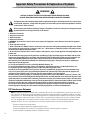
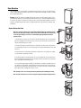
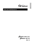
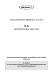
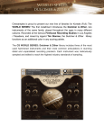
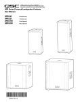
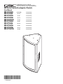
1675 MacArthur Blvd., Costa Mesa, CA, 92626 USA
Main Number (714) 754-6175 or toll free (USA only) (800) 854-4079
Customer Service(714) 957-7150 or toll free (USA only) (800) 772-2834
MD Series Powered Loudspeaker Products
User Manual
MD-FP122/64r
MD-FP122/66
MD-FP122/94r
MD-FP122/96r
MD-FP122/124r
MD-FP152/64r
MD-FP152/66
MD-FP152/94r
MD-FP152/96r
MD-FP152/124r
60° x40° (HxV)
60° x 60°
12-inch, two-way
90° x40°
12-inch, two-way
90° x 60°
12-inch, two-way
120° x40°
12-inch, two-way
60° x40°
15-inch, two-way
60° x 60°
15-inch, two-way
90° x40°
15-inch, two-way
90° x 60°
15-inch, two-way
120° x40°
15-inch, two-way
*TD-000186-00*
TD-000186-00-D
12-inch, two-way
Important Safety Precautions & Explanation of Symbols
Install in accordance with QSC Audio Product's instructions and under the supervision of a licensed Professional Engineer.
WARNING!
CAUTION: TO REDUCE THE RISK OF ELECTRIC SHOCK, DO NOT REMOVE THE COVER.
NO USER-SERVICEABLE PARTS INSIDE. REFER SERVICING TO QUALIFIED PERSONNEL.
The lightning flash with arrowhead symbol within an equilateral triangle is intended to alert the user to the presence
of uninsulated “dangerous” voltage within the product's enclosure that may be of sufficient magnitude to constitute
a risk of electric shock to humans.
The exclamation point within an equilateral triangle is intended to alert the user to the presence of important operating and maintenance (servicing) instructions in this manual.
1- Read these instructions.
2- Keep these instructions.
3- Heed all warnings.
4- Follow all instructions.
5- WARNING: To prevent fire or electric shock, do not expose this equipment to rain or moisture. Do not use this apparatus
near water.
6- Clean only with a dry cloth.
7- Allow a minimum of 4” (100mm) clearance at cabinet back for convection cooling. Keep anything that might restrict airflow
away from the rear of the enclosure (i.e draperies, fabric, etc...). Do not block any ventilation openings. This product contains
an internal power amplifier that produces heat.
8- Do not install near any heat sources such as radiators, heat registers, stoves, or other apparatus (including amplifiers) that
produce heat.
9- Do not defeat the safety purpose of the polarized or grounding-type plug. A polarized plug has two blades with one wider
than the other. A grounding plug has two blades and a grounding prong. The wide blade or third prong are provided for your
safety. If the provided plug does not fit your outlet, consult an electrician for the replacement of the obsolete outlet.
10- Protect the power cord from being walked on or pinched, particularly plugs, convenience receptacles, and the point
where they exit from the apparatus.
11- Use only attachments/accessories specified by QSC Audio Products, Inc.
12- Use only with hardware, brackets, stands, and components sold with the apparatus or by QSC Audio Products, Inc.
13- Unplug the apparatus during lightning storms or when unused for long periods of time.
14- Refer all servicing to qualified service personnel. Servicing is required when the apparatus has been damaged in any
way, such as power supply cord or plug is damaged, liquid has been spilled or objects have fallen into the apparatus, the
apparatus has been exposed to rain or moisture, does not operate normally, or has been dropped.
15- Before placing, installing, rigging, or suspending any speaker product, inspect all hardware, suspension, cabinets, transducers, brackets and associated equipment for damage. Any missing, corroded, deformed, or non-load rated component could
significantly reduce the strength of the installation, placement or array. Any such condition severely reduces the safety of the
installation and should be immediately corrected. Use only hardware which is rated for the loading conditions of the installation and any possible short-term, unexpected overloading. Never exceed the rating of the hardware or equipment.
16- Consult a licensed, Professional Engineer regarding physical equipment installation. Ensure that all local, state and
national regulations regarding the safety and operation of flying equipment are understood and adhered to.
FCC Interference Statement
NOTE: This equipment has been tested and found to comply with the limits for a class B digital device, pursuant to part 15 of the FCC
rules. These limits are designed to provide reasonable protection against harmful interference in a residential installation. This equipment generates, uses, and can radiate radio frequency energy and if not installed and used in accordance to the instructions, may cause
harmful interference to radio communications. However, there is no guarantee that interference will not occur in a particular installation. If this equipment does cause harmful interference to radio or television reception, which can be determined by switching the
equipment off and on, the user is encouraged to try to correct the interference by one or more of the following measures:
•Reorient or relocate the receiving antenna.
•Increase the separation between the equipment and the receiver.
•Connect the equipment into an outlet on a circuit different from that to which the receiver is connected.
•Consult the dealer or an experienced radio or TV technician for help.
2
Introduction
Congratulations and thank you for your purchase of this professional, powered loudspeaker product. To get the most from your investment, we
recommend you review all the information provided in this User Manual.
The Modular Design (or “MD”) self-powered loudspeakers provide excellent sound quality, quality construction, energy-efficient and clean
power amplification on-board, and a multitude of models with common cabinet design making installation easier. Its self-contained installation
solution, optimized equalization and crossover, rotatable high frequency horn, 15 attachment points, and minimal weight increase over non-powered versions enable the powered MD series to solve more application challenges than competing designs. Available in black or white, they are
the perfect solution for house-of-worship, performing arts center, and arena applications that demand flexible and excellent-sounding system
solutions.
All models are self-powered, using highly efficient class-D amplifiers and high-frequency switch-mode power supplies. AC line connection is
fast and easy; a locking, quick-disconnect Neutrik PowerCon ensures reliable AC mains connection while providing an easy-to-remove power
cord for cabinet mobility. Audio is input to the self-powered loudspeaker via an XLR connector with an additional XLR output for daisy-chaining.
Handles are provided on black-colored enclosures, while white-colored enclosures are not equipped with handles. Features vary by model, so
please refer to sales brochures for specific model information.
1- Filter Switch
2- Gain Adjuster
3- Signal and Clip Indicator LEDs
4- Input and Output XLR connectors
5- Handles, only on black enclosures
6- Cooling Fan
7- AC Mains Entrance (PowerCon Receptacle)
8- Power ON LED Indicator
9- Serial Number Plate
10- Power Switch (AC Mains Switch)
NOTE! Handles are provided on black-colored enclosures only! White-colored enclosures are not equipped with handles.
Installation
There are fifteen (15) load-rated pick points on the MD enclosure; four each on the top and on the bottom, two each on the sides, and three on
the rear of the enclosure. As shipped from the factory, each pick point has a strength rated flat head bolt installed. These bolts are load bearing
components of the enclosure. Do not remove these bolts except to replace a bolt with a forged-shoulder eye bolt. If a flat head screw is lost, contact QSC’s Technical Services department for a replacement.
Ensure all pick-point fasteners are installed and correctly tightened in order to maintain enclosure’s rated strength. Additionally, air
leaks resulting from missing hardware will degrade the loudspeaker’s performance.
Use only 3/8-inch, 16 threads per inch forged shoulder eye bolts, QSC part number SR-000096-00. Contact QSC Technical Services department for complete information.
Before placing, installing, rigging, or suspending any speaker product, inspect all hardware, suspension, cabinets, transducers, brackets and associated equipment for damage. Any missing, corroded, deformed, or non-load rated component could significantly reduce the
strength of the installation, placement or array. Any such condition severely reduces the safety of the installation and should be immediately corrected. Use only hardware which is rated for the loading conditions of the installation and any possible short-term, unexpected
overloading. Never exceed the rating of the hardware or equipment.
Consult a licensed, Professional Engineer regarding physical equipment installation. Ensure that all local, state and national regulations
regarding the safety and operation of flying equipment are understood and adhered to.
3
Installation (continued)
Cooling
This product’s internal power amplifier produces some heat as a normal condition of operation. Allow a minimum of
4” (100mm) clearance at cabinet back for adequate ventilation, and avoid exposing to hot lights or direct sunlight.
For ambient temperatures below 104°F (40°C) the fan will normally remain off. Between 104°F (40°C) and 122°
(50°F) the fan will run for increasing periods of time. Above 130°F (55°C) the internal overheating protection will
begin to operate. The unit will reduce its gain, and possibly mute. If the fan appears to be running constantly, try to
reduce the ambient temperature to ensure full performance.
Keep anything that might restrict airflow away from the rear of the enclosure (i.e draperies, fabric, etc...).
Do not install enclosures with their rear panels exposed to direct sunlight. Direct sunlight will heat the
amplifier module and reduce its ability to produce full output. Install sunshades if the application merits.
Maximum ambient temperature for full performance to specification is 45° C. (113° F.).
Do not install enclosures where exposed to rain or other water sources. The enclosure is not weatherproof.
Outdoor installations must provide protection from the elements.
AC Mains
AC Mains Connection
Orient the PowerCon connector with the PowerCon socket located on the rear panel of the loudspeaker. It is keyed and will only fit into the socket when aligned properly. Insert the connector fully
and rotate clockwise until the locking mechanism engages.
The correct AC line voltage is shown on the serial number label, on the rear panel. Connecting to the wrong
line voltage may damage the amplifier or increase the risk of electric shock.
AC Mains Disconnection
To remove the connector, pull back on the metal locking tab and turn the connector counterclockwise until it
stops, then pull to remove the connector form the socket.
Power Switch
Push in on the top of the rocker switch to apply AC mains power to the powered loudspeaker. Push in on the bottom
of the rocker switch to turn the powered loudspeaker off.
When turned on, the blue Power indicator LED and the red LIM (limiter) indicator LED will illuminate; after a few seconds the red LIM indicator will extinguish.
LED Power Indicator
The blue LED Power indicator will illuminate when the AC Power switch is in the “ON” position, the AC
mains power cord is connected properly, and the AC mains are functioning properly. The LED Power indicator will extinguish when the AC Power switch is in the “off” position or AC mains power has been
removed from the loudspeaker.
If the Power indicator does not illuminate when the Power switch is placed in the “on” position, verify
the AC mains line cord is properly attached to the loudspeaker and plugged into the AC outlet. Verify the
outlet is functioning properly.
If the AC mains cordset is serviceable and the AC mains outlet is operating properly, but the loudspeaker
fails to operate, the loudspeaker may require servicing. Contact QSC’s Technical Services department.
4
Input/Output Connections
The active MD has a balanced 3-pin female XLR input marked IN and a male XLR output connector marked OUT. These connectors are wired in parallel, enabling connection of multiple
enclosures in a “daisy-chain” fashion.
Balanced connections are recommended for less AC hum and interference, especially with
long cable runs. Unbalanced connections may be suitable for short cables. The signal's source
impedance should be less than 600 ohms.
Input connection
Insert the male XLR input into the jack marked IN. Ensure the connector is fully seated. The
input impedance is 12k ohm balanced or 6k ohm unbalanced.
Input (IN) and Output
(OUT) Connectors
Balanced inputs: Connect to the plug as shown.
1= shield (ground)
3= minus (-)
2= plus (+)
Unbalanced inputs: Connect to the plug as shown. Pin 3 and pin 1 must be connected with
a jumper as shown.
1= shield (ground)
3= jumper to pin 1
2= plus (+)
Output Connection
Insert the female XLR connector into the jack marked OUT. Connect the other end of the cable
to the next down-stream audio device’s input connector.
Gain Control
The Gain control is recessed and can be adjusted with a small screwdriver or flat tool. Turn
the gain control clockwise to increase gain and counter clockwise to decrease gain. The
attenuation in dB (from maximum) is shown on the label.
The Gain control is marked in dB of attenuation. There are 21 detents for repeatable adjustments. The upper 14 steps are about 1 dB each, and settings should normally be made within
this range. The range below -14 dB should not be used for normal program levels, as the input
headroom could be exceeded, but can be used for testing at reduced levels. At the minimum
setting, the signal is completely cut off.
Filter Select Switch
Gain Control
Filter Select Switch
Above the Gain control is a small toggle switch that selects either Full Range operation or
applies a 100 Hz Lo-Cut filter to the system.
Full Range Setting
Use the Full Range setting for applications without subwoofers or dedicated low-frequency
enclosures.
100 Hz Lo-Cut Setting
Use the 100 Hz Lo-Cut setting for applications with optional subwoofers or low-frequency systems.
The two-way wedge will have its low-frequency content below 100 Hz filtered at 24dB per
octave, yielding less distortion at low frequencies and provide improved clarity in the mid-frequencies.
5
SIG (Signal) Indicator LED
The green SIG (signal) indicator alerts the user to the presence of an input signal to the MD
loudspeaker.
SIG (signal)
indicator LED
Normal Indication
The green SIG indicator illuminates when the input signal exceeds -25 dB.
If No Indication
Check Gain settings and increase gain if necessary. Check input connections and audio source
for signal. If the red LIM LED illuminates, refer to the LIM indicator section, below.
Abnormal Indication
If the green SIG LED illuminates with no signal input, there may be system oscillations or some
other malfunction. Disconnect the input or fully reduce the gain. If the green SIG LED remains
on, the amp may need servicing.
LIM (Limiter) Indicator LED
The red LIM indicator alerts the user to several abnormal conditions within the MD loudspeaker:
Continuous Bright Red Light
• Indicates protective mute mode.
• The speaker normally passes through muting for several seconds after applying power, after
which the light should go out, and sound should be heard.
• If the speaker enters Mute during operation, it has either overheated or developed a fault.
• Overheating should correct itself within 1-2 minutes, after which sound should resume. See
below for a full explanation of thermal protection.
• Short periods of muting indicate a component fault. In this case AC power should be removed
and the speaker serviced.
Momentary Bright Red Flashes
• During operation, bright flashing indicates clipping (overdrive distortion).
• This is normally due to excessive volume, and will likely be accompanied by audible distortion.
• If the speaker mutes repeatedly during peaks, there may be a component fault. AC power should
be removed and the speaker serviced.
Continuous Half-bright Light
• Indicates that the internal limiter is reducing gain, due to prolonged clipping and/or excessive
temperature.
• After several seconds of severe clipping, the limiter will reduce power to protect the speaker
and improve the sound. This results in a steady, half-bright red indication. Any further clipping
will still result in bright flashes on top of the steady half-bright indication. When the program
level is reduced, the limiter will clear after several seconds, and the red indicator will go out.
• If the power module overheats, the first response is to trigger limiting, to reduce volume and
limit further temperature rise. This results in a steady half-bright illumination that does not clear
even after reducing program level. It may take several minutes for temperature to drop and clear
the limiter. During this time, the exposed heat sink will feel uncomfortably hot to the touch. If
overheating continues, the amplifier will ultimately mute, resulting in a full-bright red indication.
When muting clears, the amplifier will resume operation, with thermal limiting still active until
it further cools off.
• Overheating is usually caused by excessive ambient temperature, since the internal temperature
rise of the Class-D power module is relatively low. Protect the speaker from excessive temperatures, such as being placed over a heater vent, or allowing direct sunlight to impinge upon the
heat sink surface.
6
LIM (limiter)
indicator LED
Location of Pick Points
Pick Points
There are fifteen (15) load-rated pick points on the MD enclosure; four each on the
top and on the bottom, two each on the sides, and three on the rear of the enclosure. These pick points are indicated with arrowheads on the illustration. Note the
pick points on the cabinet bottom are not shown, but are identical to those indicated on the cabinet top.
As shipped from the factory, each pick point has a strength rated flat head bolt
installed. These bolts are load bearing components of the enclosure. Do not
remove these bolts except to replace a bolt with a forged-shoulder eye bolt. If a
flat head screw is lost, contact QSC’s Technical Services department for a replacement.
Ensure all pick-point fasteners are installed and correctly tightened in
order to maintain enclosure’s rated strength. Additionally, air leaks resulting from missing hardware will degrade the loudspeaker’s performance.
Use only 3/8-inch, 16 threads per inch forged shoulder eye bolts, QSC part
number SR-000096-00. Contact QSC Technical Services department for
complete information.
Before placing, installing, rigging, or suspending any speaker product,
inspect all hardware, suspension, cabinets, transducers, brackets and
associated equipment for damage. Any missing, corroded, deformed, or
non-load rated component could significantly reduce the strength of the
installation, placement or array. Any such condition severely reduces the
safety of the installation and should be immediately corrected. Use only
hardware which is rated for the loading conditions of the installation and
any possible short-term, unexpected overloading. Never exceed the rating
of the hardware or equipment.
Consult a licensed, Professional Engineer regarding physical equipment
installation. Ensure that all local, state and national regulations regarding
the safety and operation of flying equipment are understood and adhered
to.
Pick Points
Pick Points
Pick Points
4 additional Pick Points located on enclosure
bottom.
NOTE! Handles are provided on black-colored
enclosures only! White-colored enclosures
are not equipped with handles.
7
Rigging the Installation (continued)
Rigging the Installation
Rules for Suspension
•Correct use of all suspension hardware and components is imperative in sound system rigging and deployment.
•Always calculate suspended loads before lifting to ensure suspension components and hardware are used within their respective load limits.
•Research local codes and regulations to fully understand the requirements for suspended loads in the venue in which the equipment is to be
suspended.
•Use only shackle holes for suspension of array.
•Be absolutely certain of the integrity of any structural member intended to support suspended loads. Hidden structural members can have hidden structural weakness.
•Consult a Professional Mechanical or Structural Engineer licensed in the jurisdiction of the sound system installation to review, verify, and
approve all attachments to the building or structure.
•Never assume anything- Owner or third-party supplied suspension attachment points may not be adequate for the loads to be suspended.
•Employ the services of a Professional Rigger for hoisting, positioning, and attaching the equipment to the supporting structure.
•Always inspect all components (enclosures, suspension brackets, pins, frames, bolts, nuts, slings, shackles, etc.) for cracks, wear, deformation, corrosion, missing, loose, or damaged parts that could reduce the strength of the assembly before lifting. Discard any worn, defective, or
suspect parts and replace them with new appropriately load-rated parts.
Shock Loading
When a load is either moved or stopped, its static weight is magnified. Sudden movements can magnify the static weight several times. This
magnification of static weight is termed "shock loading". Shock loading poses a danger to equipment and workers. The effects of shock loading
can be instantaneous, or they may remain undetected unless the equipment is visually damaged. Avoiding shock loading requires careful planning and knowledge of equipment, rigging, and lifting practices.
Shock loading of equipment and structures is usually confined to lifting and installation, but natural forces (winds, earthquakes) can impose
shock loads several times the static load. This is why structures and suspension equipment must be capable of supporting several times the
weight of the equipment suspended.
MD Working Load Limits and Design Factors
Table 1 lists the MD suspension components and provides Working Load Limit data at various Design Factors. The tabulated Design Factors are
for static loads only. The choice of which Design Factor to use will depend upon the jurisdiction and venue of installation, as well as the conditions of suspension. Dynamic conditions are determined by unknown, installation-specific factors and should be referred to a Licensed Structural
Engineer for clarification before proceeding with any suspension of the equipment. The data presented is based upon the listed component
weights:
Table 1: MD Working Load Limits
8
Suspension Points
7:1 Design Factor
10:1 Design Factor
12:1 Design Factor
Top & Side Panels
457 lb (207 kg)
320 lb (145 kg)
267 lb (121 kg)
Rear Panels
314 lb (143 kg)
220 lb (100 kg)
183 lb (83 kg)
Horn Rotation
The coverage angles for each model, as shipped from the factory, are show in the specifications
section. If desired the high-frequency driver/horn assembly can be rotated 90° in order to change
the coverage angle planes.
Example: An MD-FP122/64r as shipped from the factory has a nominal coverage of 60° in the
horizontal plane and 40° in the vertical plane when the enclosure is oriented normally (vertically,
as shown at the right). To change the coverage to 40° in the horizontal plane and 60° in the vertical plane, the high-frequency driver/horn assembly would have to be removed, rotated 90°, and
reinstalled.
How to Rotate the Horn
Note! It is always best to have an assistant when working with large assemblies such as
this enclosure. The grill assembly is under tension when installed! Be sure to temporarily
secure the grill with tape or have an assistant hold the grill edge while removing its
retaining screws.
1- Remove the four screws from one side of the grill while having an assistant hold the
grill from springing free. Remove the four screws from the other side of the grill. Place
the grill and retaining screws aside.
2- Remove the eight horn retaining screws. Carefully lift the horn from its mounting recess while being careful not to tear or pull away the foam gasket between the horn and
enclosure.
3- Rotate the horn to the desired position and set back into its mounting recess, being
sure the gasket is properly positioned.
4- Install the eight horn retaining screws. Do not fully tighten the screws until all have
been installed and finger-tightened. This will help to prevent the chance of cracking the
horn. Fully tighten the retaining screws.
5- Position and align the grill assembly for reinstallation. Install four retaining screws on
one side; do not fully tighten. carefully bend the grill around the front of the enclosure
and install the remaining four retaining screws. It is easier to have an assistant hold the
grill in place while installing the final four screws.
Grill retaining screws are to be torqued to 30-35 pound inch (0.35 -0.40 kilogram meter)
Horn assembly retaining screws are to be torqued to 40 pound inch (0.46 kilogram meter)
Specifications
MD-FP122/64r
MD-FP122/66
MD-FP122/94
MD-FP122/96r
Frequency Response, -6dB
55 Hz - 17.5 kHz
55 Hz - 17.5 kHz
55 Hz - 19.5 kHz
55 Hz - 16.5 kHz
55 Hz - 19 kHz
Frequency Range, -10dB
50 Hz - 18 kHz
50 Hz - 19.5 kHz
50 Hz - 20 kHz
50 Hz - 19.5 kHz
50 Hz - 20 kHz
Maximum Output
129 dB continuous
139 dB peak
127 dB continuous
137 dB peak
128 dB continuous
138 dB peak
127 dB continuous
135 dB peak
126 dB continuous
137 dB peak
Nominal coverage, H x V
(as installed at factory)
Directivity Index
60°x40° rotatable
60°x60°
90°x40° rotatable
90°x60° rotatable
120°x40° rotatable
12.8
11.7
11.3
10.2
9.6
Directivity Factor
19.0
14.7
13.4
10.5
9.1
Acoustic Crossover Freq.
1.4k Hz
1.2k Hz
1.4k Hz
1.2k Hz
1.2k Hz
Transducer Description
LF: 12” (305mm) diameter, 4” (102mm) voice coil, ferrite magnet
HF: 1.4” (36mm) exit diameter, 2.5” (64mm) voice coil, neodymium magnet, all models
Amp Power
LF: 800W, HF: 200W, all models
Input Sensitivity
1.2Vrms (+4 dBu), all models
Input Headroom/Clipping
7.5Vrms (+19.5 dBu), all models
MD-FP122/124r
Input Connector/Impedance XLR female, 20k ohm, balanced, all models (pin 1:Earth, Pin 2: +, Pin 3: -)
Output Connector
XLR male, wired in parallel with Input connector
Controls, Indicators, and
Adjustments
Rotatable horn assembly, Gain control, 100 Hz high-pass filter switch, Clip/Limit (red LED), Signal presence (green
LED), AC Power (blue LED), all models
Protection, Agency certs.
Thermal limiting, On/Off muting, AC in-rush current limiting, FCC class B (conducted and radiated), UL/CE listed
Operating Voltages
Available in 120V or 230V versions (+15%, -40%)
AC Power Requirements
Pink noise (6 dB crest factor) - Idle <0.5 A (<100 BTU waste heat) / 1/8 power 2.5 A (570 BTU waste heat) / 1/3 power
5.0 A (1380 BTU waste heat), full power 15.0 A (4010 BTU waste heat)
Typical program material at full power- 2.5 A (570 BTU waste heat)
AC Power Connector
Factory supplied cordset: Neutrik Powercon on 10’ (3m) #18AWG 120V North American cordset
Dimensions
20.5” (521mm) W, 35.0” (889mm) H, 17.1” (432mm) D, including rear heatsink fins
Allow for 100mm (4.0”) of free space behind the enclosure to assure proper amplifier cooling
Weight
88 lb/40 kg, all models
Finish and Grill
All models- wear resistant textured paint finish with powder-coated perforated steel grill
Notes:
1- Maximum Peak SPL: Calculated by adding the loudspeaker’s sensitivity (1W at 1m) to the peak power (dBw) of the amplifier provided.
2- Coverage: Included angle between -6dB points, plus X, minus Y dB, 500 to 3.2k Hz, taken at ISO preferred one-third octave intervals, or for an otherwise specified frequency range.
3- Directivity Index (DI): Difference between on-axis SPL and average SPL (considering all axes) for the specified coverage range. DI= 10 log Q
4- Directivity Factor (Q): Directivity index expressed as a power ratio Q=10 exp DI/10
5- Amplifier Power: The maximum sustained power at less than 1% clipping, averaged over the intended frequency range,
6- Input Sensitivity: The sine-wave input voltage required to reach amplifier clipping, measured within the frequency range used to determine Maximum Peak SPL, with the gain on “normal” and no gain reduction
due to limiting.
7- Input Headroom/Clipping: Maximum input voltage.
8- Input Connector/Impedance: RF shunt capacitance should not reduce impedance by more than 30% at 20k Hz.
9- TBD= to be determined, data not available at time of printing
Specifications
MD-FP152/64r MD-FP152/66
Frequency Response, -6dB
50-17.5k Hz
50-19.5k Hz
Frequency Range, -10dB
45-18k Hz
Maximum Output
MD-FP152/94r
MD-FP152/96r
MD-FP152/124r
50-19.5k Hz
50-19k Hz
50-19k Hz
45-20k Hz
45-20k Hz
45-20k Hz
50-19k Hz
129 dB continuous
139 dB peak
127 dB continuous
138 dB peak
128 dB continuous
138 dB peak
126 dB continuous
136 dB peak
Nominal coverage, H x V
(as installed at factory)
Directivity Index
60°x40° rotatable
60°x60°
90°x40° rotatable
90°x60° rotatable
120°x40° rotatable
12.8
11.7
11.3
10.2
9.6
Directivity Factor
19.0
14.7
13.4
10.5
9.1
Acoustic Crossover Freq.
1.32k Hz
1.2k Hz
1.4k Hz
1.2k Hz
1.2k Hz
Transducer Description
LF: 15” (381mm) diameter, 4” (102mm) voice coil, ferrite magnet
HF: 1.4” (36mm) exit diameter, 2.5” (64mm) voice coil, neodymium magnet, all models
Amp Power
LF: 800W, HF: 200W, all models
Input Sensitivity
1.2Vrms (+4dB), all models
Input Headroom/Clipping
7.5Vrms (+19.5dB), all models
127 dB continuous
137 dB peak
Input Connector/Impedance XLR female, 20k ohm, balanced, all models
Output Connector
XLR male, wired in parallel with Input connector
Controls, Indicators, and
Adjustments
Rotatable horn assembly, Gain control, 100 Hz high-pass filter switch, Clip/Limit (red LED), Signal presence (green LED),
Power (blue LED), all models
Protection, Agency certs.
Thermal limiting, On/Off muting, AC in-rush current limiting, FCC class B (conducted and radiated emissions), UL/CE listed
Operating Voltages
Available in 120V or 230V versions (+15%, -40%)
AC Power Requirements
Pink noise (6 dB crest factor) - Idle <0.5 A (<100 BTU waste heat) / 1/8 power 2.5 A (570 BTU waste heat) / 1/3 power
5.0 A (1380 BTU waste heat), full power 15.0 A (4010 BTU waste heat)
Typical program material at full power- 2.5 A (570 BTU waste heat)
AC Power Connector
Factory supplied cordset: Neutrik Powercon on 10’ (3m) #18AWG 120V North American cordset
Dimensions
20.5” (521mm) W, 35.0” (889mm) H, 17.1” (432mm) D, including rear heatsink fins
Allow for 100mm (4.0”) of free space behind the enclosure to assure proper amplifier cooling
Weight
88 lb/41 kg All Models
Finish and Grill
All models- wear resistant textured paint finish with powder-coated perforated steel grill
Notes:
1- Maximum Peak SPL: Calculated by adding the loudspeaker’s sensitivity (1W at 1m) to the peak power (dBw) of the amplifier provided.
2- Coverage: Included angle between -6dB points, plus X, minus Y dB, 500 to 3.2k Hz, taken at ISO preferred one-third octave intervals, or for an otherwise specified frequency range.
3- Directivity Index (DI): Difference between on-axis SPL and average SPL (considering all axes) for the specified coverage range. DI= 10 log Q
4- Directivity Factor (Q): Directivity index expressed as a power ratio Q=10 exp DI/10
5- Amplifier Power: The maximum sustained power at less than 1% clipping, averaged over the intended frequency range,
6- Input Sensitivity: The sine-wave input voltage required to reach amplifier clipping, measured within the frequency range used to determine Maximum Peak SPL, with the gain on “normal” and no gain reduction due
to limiting.
7- Input Headroom/Clipping: Maximum input voltage.
8- Input Connector/Impedance: RF shunt capacitance should not reduce impedance by more than 30% at 20k Hz.
9- TBD= to be determined, data not available at time of printing
11
Dimensions
NOTE! Handles are provided on black-colored enclosures only! White-colored enclosures are not equipped with handles.
12
Warranty (USA only; other countries, see your dealer or distributor)
Disclaimer
QSC Audio Products, Inc. is not liable for any damage to amplifiers or any other equipment that is caused by negligence or improper
installation and/or use of this loudspeaker product.
QSC Audio Products 3 Year Limited Warranty
QSC Audio Products, Inc. (“QSC”) guarantees its products to be free from defective material and / or workmanship for a period of three
(3) years from date of sale, and will replace defective parts and repair malfunctioning products under this warranty when the defect
occurs under normal installation and use - provided the unit is returned to our factory or one of our authorized service stations via prepaid transportation with a copy of proof of purchase (i.e., sales receipt). This warranty provides that the examination of the return product must indicate, in our judgment, a manufacturing defect. This warranty does not extend to any product which has been subjected to
misuse, neglect, accident, improper installation, or where the date code has been removed or defaced. QSC shall not be liable for incidental and/or consequential damages. This warranty gives you specific legal rights. This limited warranty is freely transferable during
the term of the warranty period.
Customer may have additional rights, which vary from state to state.
In the event that this product was manufactured for export and sale outside of the United States or its territories, then this limited warranty shall not apply. Removal of the serial number on this product, or purchase of this product from an unauthorized dealer, will void
this limited warranty.
Periodically, this warranty is updated. To obtain the most recent version of QSC’s warranty statement, please visit www.qscaudio.com.
Contact us at 800-854-4079 or visit our website at www.qscaudio.com.\
1675 MacArthur Blvd., Costa Mesa, CA, 92626 USA
Main Number (714) 754-6175 or toll free (USA only) (800) 854-4079
Customer Service(714) 957-7150 or toll free (USA only) (800) 772-2834
© Copyright 2005, 2006, 2007 QSC Audio Products, Inc.
QSC® is a registered trademark of QSC Audio Products, Inc.
“QSC” and the QSC logo are registered with the U.S. Patent and Trademark Office
PowerCon® is a registered trademark of Neutrik® and the names of Neutrik® products referenced herein are either trademarks and/or service marks of Neutrik®.
All trademarks are the property of their respective owners.
13