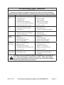
1
PAINT SPRAYER
HVLP-ELECTRIC
Model 97750
Set up And Operating Instructions
Diagrams within this manual may not be drawn proportionally.
Due to continuing improvements, actual product may differ slightly from the product described herein.
Distributed exclusively by Harbor Freight Tools®.
3491 Mission Oaks Blvd., Camarillo, CA 93011
Visit our website at: http://www.harborfreight.com
Read this material before using this product.
Failure to do so can result in serious injury.
Save this manual.
Copyright© 2008 by Harbor Freight Tools®. All rights reserved. No portion of this
manual or any artwork contained herein may be reproduced in any shape or form
without the express written consent of Harbor Freight Tools.
For technical questions or replacement parts, please call 1-800-444-3353.
Save This Manual
NOTICE is used to
address practices
not related to personal injury.
Keep this manual for the safety warnings and precautions, assembly, operating, inspection, maintenance and cleaning
procedures. Write the product’s serial
number in the back of the manual near the
assembly diagram (or month and year of
purchase if product has no number). Keep
this manual and the receipt in a safe and
dry place for future reference.
CAUTION, without
the safety alert
symbol, is used to address
practices not related to
personal injury.
General Power Tool
Safety Warnings
Important SAFETY
Information
WARNING Read all safety
warnings and instructions.
Failure to follow the warnings and
instructions may result in electric
shock, fire and/or serious injury.
Save all warnings and
instructions for future reference.
The term ″power tool″ in the
warnings refers to your lineoperated (corded) power tool.
In this manual, on the labeling,
and all other information
provided with this product:
This is the safety alert
symbol. It is used to alert
you to potential personal
injury hazards. Obey all
safety messages that
follow this symbol to avoid
possible injury or death.
1.
a.Keep work area clean and well lit.
Cluttered or dark areas invite accidents.
DANGER indicates
a hazardous
situation which, if not
avoided, will result in death or
serious injury.
b.Do not operate power tools in
explosive atmospheres, such as in
the presence of flammable liquids,
gases or dust. Power tools create
sparks which may ignite the dust or
fumes.
WARNING
indicates a
hazardous situation which, if
not avoided, could result in
death or serious injury.
CAUTION, used
with the safety
alert symbol, indicates a
hazardous situation which, if
not avoided, could result in
minor or moderate injury.
SKU 97750
Work area safety
c.Keep children and bystanders
away while operating a power tool.
Distractions can cause you to lose
control.
2.
Electrical safety
a.Power tool plugs must match the
outlet. Never modify the plug in
any way. Do not use any adapter
plugs with grounded power tools.
For technical questions, please call 1-800-444-3353.
Page 2
mask/respirator. Safety equipment
such as non-skid safety shoes, hard
hat, or hearing protection used for
appropriate conditions will reduce
personal injuries.
Unmodified plugs and matching outlets will reduce risk of electric shock.
b.Avoid body contact with grounded
surfaces such as pipes, radiators,
ranges and refrigerators. There is
an increased risk of electric shock if
your body is grounded.
c.Prevent unintentional starting.
Ensure the Power Switch (33) is in
the off-position before connecting
to the power source, picking up or
carrying the tool. Carrying power
tools with your finger on the Power
Switch or energizing power tools that
have the Power Switch on invites accidents.
c.Do not expose power tools to rain
or wet conditions. Water entering
a power tool will increase the risk of
electric shock.
d.Do not abuse the Power Cord (34).
Never use the Cord for carrying,
pulling or unplugging the power
tool. Keep Cord away from heat,
oil, sharp edges or moving parts.
Damaged or entangled Cords increase the risk of electric shock.
d.Remove any adjusting key or
wrench before turning the power
tool on. A wrench or a key left attached to a rotating part of the power
tool may result in personal injury.
e.When operating a power tool outdoors, use an extension cord suitable for outdoor use. Use of a cord
suitable for outdoor use reduces the
risk of electric shock.
e.Do not overreach. Keep proper
footing and balance at all times.
This enables better control of the
power tool in unexpected situations.
f. Dress properly. Do not wear loose
clothing or jewelry. Keep your
hair, clothing and gloves away
from moving parts. Loose clothes,
jewelry or long hair can be caught in
moving parts.
f. If operating a power tool in a damp
location is unavoidable, use a
Ground Fault Circuit Interrupter
(GFCI) protected supply. Use of
a GFCI reduces the risk of electric
shock.
3.
Personal safety
a.Stay alert, watch what you are doing and use common sense when
operating a power tool. Do not use
a power tool while you are tired
or under the influence of drugs,
alcohol or medication. A moment
of inattention while operating power
tools may result in serious personal
injury.
b.Use safety equipment. Always
wear ANSI-approved safety impact
goggles and NIOSH-approved dust
SKU 97750
4.
Power tool use and care
a.Do not force the power tool. Use
the correct power tool for your application. The correct power tool will
do the job better and safer at the rate
for which it was designed.
b.Do not use the power tool if the
Power Switch (33) does not turn
it on and off. Any power tool that
cannot be controlled with the Power
Switch is dangerous and must be
repaired.
For technical questions, please call 1-800-444-3353.
Page 3
c.Disconnect the Power Cord (34)
from the power source before making any adjustments, changing accessories, or storing power tools.
Such preventive safety measures
reduce the risk of starting the power
tool accidentally.
d.Store idle power tools out of the
reach of children and do not allow
persons unfamiliar with the power
tool or these instructions to operate the power tool. Power tools are
dangerous in the hands of untrained
users.
e.Maintain power tools. Check for
misalignment or binding of moving
parts, breakage of parts and any
other condition that may affect the
power tool’s operation. If damaged, have the power tool repaired
before use. Many accidents are
caused by poorly maintained power
tools.
f. Keep the power tool clean. Improper cleaning of the Paint Sprayer and
its accessories is a common reason
for the Spray Gun to jam or not perform properly.
g.Use the power tool, accessories
and tool bits etc. in accordance
with these instructions, taking into
account the working conditions
and the work to be performed. Use
of the power tool for operations different from those intended could result
in a hazardous situation.
5.
Service
a.Have your power tool serviced by
a qualified repair person using
only identical replacement parts.
This will ensure that the safety of the
power tool is maintained.
SKU 97750
Specific Safety
Warnings
1.
Maintain labels and nameplates
on the Paint Sprayer. These carry
important safety information. If unreadable or missing, contact Harbor
Freight Tools for a replacement.
2.
Avoid unintentional starting. Prepare to begin work before turning on
the Paint Sprayer.
3.
For your safety, maintenance
should be performed regularly by
a qualified service technician. The
Paint Sprayer and its accessories
must be thoroughly cleaned after
every use.
4.
Do not spray near open flames,
pilot lights, stoves, heaters, or any
other heat source. Most solvents
and coatings are highly flammable,
particularly when sprayed. Do not
smoke while spraying.
5.
Read all of the information concerning coating products and
cleaning solvents. Chlorinated solvents (i.e., trichlorethylene and methylene chloride) can chemically react
with aluminum and may explode.
Many Paint Sprayers contain aluminum. If you have any doubt about
potential chemical reactions contact
the solvent or coating manufacturer.
6.
Materials used when painting or
cleaning may be harmful or fatal
if inhaled or swallowed. Only use
in an area with adequate ventilation.
Use a NIOSH-approved dust mask
or respirator when painting or using
solvents.
For technical questions, please call 1-800-444-3353.
Page 4
7.
Never release the Lower Cover (24)
while the Cup (27) is pressurized.
8.
Industrial applications must follow
OSHA requirements.
9.
Make sure air intake guard is in
place before use.
10. Never point a Spray Gun at people
or animals. Serious injury could occur.
11. Spraying hazardous materials may
result in death or serious injury.
Do not spray pesticides, acids, corrosive materials, fertilizers, and toxic
chemicals.
12. Do not leave the Paint Sprayer unattended when it is plugged into an
electrical outlet. Turn off the tool,
and unplug it from its electrical outlet
before leaving.
13. This product is not a toy. Keep it
out of reach of children.
14. People with pacemakers should
consult their physician(s) before
use. Electromagnetic fields in close
proximity to heart pacemaker could
cause pacemaker interference or
pacemaker failure. In addition, people with pacemakers should:
• Avoid operating alone.
• Do not use with power switch locked
on.
• Properly maintain and inspect to
avoid electrical shock.
• Any power cord must be properly
grounded. Ground Fault Circuit Interrupter (GFCI) should also be implemented – it prevents sustained electrical shock.
and other construction activities,
contains chemicals known [to the
State of California] to cause cancer, birth defects or other reproductive harm. Some examples of
these chemicals are:
• Lead from lead-based paints
• Crystalline silica from bricks and cement or other masonry products
• Arsenic and chromium from chemically treated lumber
Your risk from these exposures varies, depending on how often you do
this type of work. To reduce your
exposure to these chemicals: work in
a well ventilated area, and work with
approved safety equipment, such as
those dust masks that are specially
designed to filter out microscopic
particles. (California Health & Safety
Code § 25249.5, et seq.)
16. WARNING! The brass components
of this product contain lead, a chemical known to the State of California
to cause birth defects (or other reproductive harm). (California Health &
Safety Code 25249.5, et seq.)
17. The warnings, precautions, and
instructions discussed in this instruction manual cannot cover all
possible conditions and situations
that may occur. It must be understood by the operator that common
sense and caution are factors which
cannot be built into this product, but
must be supplied by the operator.
Save these
instructions.
15. Some dust created by power sanding, sawing, grinding, drilling,
SKU 97750
For technical questions, please call 1-800-444-3353.
Page 5
Grounding
of electric shock. (See 3-Prong Plug
and Outlet.)
To prevent
electric shock 2. The grounding prong in the Plug is
connected through the green wire inand death from
side the cord to the grounding system
incorrect grounding
in the tool. The green wire in the cord
wire connection:
must be the only wire connected to
Check with a qualified
the tool’s grounding system and must
electrician if you are in doubt
never be attached to an electrically
as to whether the outlet is
“live” terminal. (See 3-Prong Plug
properly grounded. Do not
and Outlet.)
modify the Power Cord Plug
(34) provided with the tool.
3. The tool must be plugged into an
Never remove the grounding
appropriate outlet, properly installed
prong from the Plug. Do not
and grounded in accordance with all
use the tool if the Power Cord
codes and ordinances. The Plug and
or Plug is damaged. If
outlet should look like those in the
damaged, have it repaired by
preceding illustration. (See 3-Prong
a service facility before use. If
Plug and Outlet.)
the Plug will not fit the outlet,
have a proper outlet installed
Double Insulated Tools: Tools
by a qualified electrician.
with Two Prong Plugs
Grounded Tools: Tools with Three
Prong Plugs
Outlets for 2-Prong Plug
1.
3-Prong Plug and Outlet
1.
Tools marked with “Grounding Required” have a three wire cord and
three prong grounding Plug. The
plug must be connected to a properly
grounded outlet. If the tool should
electrically malfunction or break
down, grounding provides a low
resistance path to carry electricity
away from the user, reducing the risk
SKU 97750
Tools marked “Double Insulated” do
not require grounding. They have
a special double insulation system
which satisfies OSHA requirements
and complies with the applicable
standards of Underwriters Laboratories, Inc., the Canadian Standard
Association, and the National Electrical Code. (See Outlets for 2-Prong
Plug.)
For technical questions, please call 1-800-444-3353.
Page 6
3.
4.
5.
6.
As the distance from the supply outlet
increases, you must use a heavier
gauge extension cord. Using extension cords with inadequately sized
wire causes a serious drop in voltage,
resulting in loss of power and possible tool damage.
(See Table A.) The smaller the
gauge number of the wire, the greater
the capacity of the cord. For example, a 14 gauge cord can carry a
higher current than a 16 gauge cord.
(See Table A.)
RECOMMENDED MINIMUM WIRE
GAUGE FOR EXTENSION CORDS*
(120/240 VOLT)
NAMEPLATE
AMPERES
(at full load)
0 – 2.0
18
18
18
18
16
2.1 – 3.4
18
18
18
16
14
3.5 – 5.0
18
18
16
14
12
5.1 – 7.0
18
16
14
12
12
7.1 – 12.0
18
14
12
10
-
12.1 – 16.0
14
12
10
-
-
16.1 – 20.0
12
10
-
-
-
TABLE A
* Based on limiting the line
voltage drop to five volts at
150% of the rated amperes.
Symbology
When using more than one extension cord to make up the total length,
make sure each cord contains at
least the minimum wire size required.
(See Table A.)
If you are using one extension cord
for more than one tool, add the
nameplate amperes and use the sum
to determine the required minimum
cord size. (See Table A.)
If you are using an extension cord
outdoors, make sure it is marked with
the suffix “W-A” (“W” in Canada) to
indicate it is acceptable for outdoor
use.
EXTENSION CORD
LENGTH
150’
2.
Grounded tools require a three wire
extension cord. Double Insulated
tools can use either a two or three
wire extension cord.
Protect the extension cords from
sharp objects, excessive heat, and
damp or wet areas.
100’
1.
7.
75’
Extension Cords
extension cord or have it repaired by
a qualified electrician before using it.
50’
Double insulated tools may be used
in either of the 120 volt outlets shown
in the preceding illustration. (See
Outlets for 2-Prong Plug.)
25’
2.
Double Insulated
Canadian Standards Association
Underwriters Laboratories, Inc.
V~
A
Volts Alternating Current
Amperes
No Load Revolutions per Minute
n0 xxxx/min. (RPM)
Make sure the extension cord is properly wired and in good electrical condition. Always replace a damaged
SKU 97750
For technical questions, please call 1-800-444-3353.
Page 7
Specifications
Electrical
Requirements
120 V~ / 60 Hz / 450 Watts
5.5 Amps (Start Up)
3.3 Amps (Load & No Load)
Motor Speed: 30,000 RPM
Power Plug: 2-Prong
Power Switch: ON/OFF Rocker
Spray Cup Capacity
1 Quart
Output Pressure
1.45 to 4.35 PSI
Activation Method
Trigger Style
Fluid Control Knob
Clockwise (For round pattern)
Counterclockwise (For flat pattern)
Air Control
Adjustable Lever
Adjustable Spray
Patterns
Horizontal (2.0” H x 6-1/4” W)
Vertical (6-1/4” H x 2.0” W)
Round (2-1/2” Diameter)
Product Limitations
Not recommended for use with latex
and other water-based paints.
Polypropylene Housing
Rubber/Thermoplastic Hose
Brass Needle & Knob
Construction Materials Aluminum Paint Cup & Nozzle
Sheet Steel Trigger
Polyester Shoulder Strap
Die Cast Aluminum Spray Gun
To prevent
serious injury
from accidental
operation:
Turn the Power Switch (33) of
the Paint Sprayer to its “OFF”
position and unplug the tool
from its electrical outlet
before assembling, operating,
or making any adjustments to
the tool.
Note: For additional information regarding
the parts listed in the following pages,
refer to the Assembly Diagram near
the end of this manual.
FLUID CONTROL SCREW
(19)
POWER SWITCH
(33)
AIR CONTROL LEVER
(13)
TRIGGER
(6)
Unpacking
AIR
NOZZLE
(4)
When unpacking, check to make sure
that the item is intact and undamaged. If
any parts are missing or broken, please
call Harbor Freight Tools at the number
shown on the cover of this manual as soon
as possible.
CUP
(27)
FIGURE A
AIR HOSE
(31)
PRODUCT FEATURES
Read the entire Important
Safety Information section
at the beginning of this manual
including all text under
subheadings therein before set
up or use of this product.
SKU 97750
MOTOR
(32)
PREPARATION
1.
IMPORTANT: Due to the viscosity of
latex and other water-based paints,
they are NOT recommended for use
with this HVLP Paint Sprayer.
For technical questions, please call 1-800-444-3353.
Page 8
Work Piece and Work Area Set Up 4. Plug the Power Cord (34) into the
1.
Designate a work area that is clean
and well-lit. The work area must not
allow access by children or pets to
prevent injury and distraction.
2.
Route the Power Cord (34) along a
safe route to reach the work area
without creating a tripping hazard
or exposing the Power Cord to possible damage. The Power Cord must
reach the work area with enough
extra length to allow free movement
while working.
3.
Secure loose workpieces using a vise
or clamps (not included) to prevent
movement while working.
4.
There must not be hazardous objects, such as utility lines or foreign
objects, nearby that will present a
hazard while working.
5.
Cover all furniture, decorations,
floors, walls, etc. not intended to be
painted.
6.
Only paint in well ventilated dust free
area.
nearest 120 volt, grounded, electrical
outlet. Then turn the Power Switch
(33) to its “ON” position.
(See Figure A, on page 8.)
5.
Adjust the air pressure during operation with the Trigger (6) and the
Air Control Lever (13). Turn the Air
Control Lever clockwise to provide
less air to the Spray Gun. Turn the
Air Control Lever counterclockwise
to provide more air to the Spray Gun.
(See Figure A, on page 8.)
6.
Set up a piece of scrap material to
practice on. While practicing on the
scrap material, check to see that the
paint/fluid you are spraying has the
appropriate consistency. If it appears
too thick, add a very small amount of
thinner (not included).
7.
To change the direction of the fan
from horizontal to vertical, loosen the
Air Cap Screw (5) and turn the Air
Nozzle (4) 90 degrees. After the adjustment, tighten the Air Cap Screw.
(See Figure B.)
AIR CAP SCREW (5)
FIGURE B
Tool Set Up
1.
Mix and thin the paint or other fluid
thoroughly according to the manufacturer’s directions.
2.
Carefully strain the paint/fluid through
a paint strainer or piece of cheese
cloth.
3.
Fill the Cup (27) to approximately
3/4 full. Then attach the Cup to the
Spray Gun. (See Figure A, on page
8.)
SKU 97750
HORIZONTAL FAN
AIR NOZZLE (4)
8.
VERTICAL FAN
To set the pattern size specific to the
job, use the Fluid Control Screw (19).
Turn it clockwise for a round pattern.
Turn the Screw counterclockwise (all
the way open) to flatten the pattern.
(See Figure C, next page.)
For technical questions, please call 1-800-444-3353.
Page 9
If you stop the Spray Gun for even
just a slight pause while spraying, the
paint/fluid will build up and run down
the workpiece. (See Figure E.)
FIGURE C
ROUND/CLOSED
FLAT/OPEN
9.
FIGURE E
After setting up a piece of scrap material, squeeze the Trigger (6) in short
bursts while turning the Fluid Control
Screw (19) counterclockwise and
observe the pattern for consistency.
Too much air may cause the spray
to come out too fine. Reduce the air 2.
pressure or allow more paint/fluid to
come out by opening the Fluid Control
Screw. If the spray appears too thick
(you see globs of paint/fluid), close
down the Fluid Control Screw slowly,
checking the mixture after each adjustment. (See Figure D.)
INCORRECT
CORRECT
To ensure you don’t allow paint to build
up, start moving the Spray Gun before
you squeeze the Trigger (6). When
you are finished spraying, release the
Trigger before you stop moving the
Spray Gun. Doing so will eliminate
distinct overlaps, producing a blended
(feathered) affect. (See Figure F.)
FIGURE F
(TOP VIEW)
TOO FINE
(LOOSEN)
BEGIN
STROKE
3.
TECHNIQUES
1.
Always keep the Spray Gun at right
angles to the workpiece. Pull the
Trigger (6) slowly and move the Spray
4.
Gun in parallel strokes to the object
being painted. Keep the distance
from the object being painted at 6” to
9”. This may slightly differ depending
on the flow adjustment and the paint/
fluid being sprayed. Do not stop the
Spray Gun movement while spraying.
SKU 97750
(EVEN COVERAGE)
CORRECT
(90°)
FIGURE D
TOO COURSE
(TIGHTEN)
(HEAVIER COAT
ON ONE SIDE,
UNEVEN COVERAGE)
SQUEEZE
TRIGGER
(6)
RELEASE
TRIGGER
(6)
END
STROKE
NOTE: The speed of the stroke, the
adjustment of the Fluid Control Screw
(19), and the distance from the workpiece will determine how much paint/
fluid is being applied. To get the best
results, try to apply two thin coats of
paint/fluid versus one thick coat.
When finished, thoroughly clean out
the Paint Sprayer and its accessories.
(See “Maintenance and Servicing”
section, next page.)
For technical questions, please call 1-800-444-3353.
Page 10
Maintenance And
Servicing
Procedures not specifically
explained in this manual
must be performed only by a
qualified technician.
quickly which will render the Spray
Gun useless. It is extremely difficult
to remove dry paint/fluid from small
passages within the Gun.
3.
To prevent
serious injury
from accidental
operation:
Turn the Power Switch (33) of
the Paint Sprayer to its “OFF”
position and unplug the tool
from its electrical outlet
before performing any
inspection, maintenance, or
cleaning procedures.
• Oil-based paints/fluids: Use mineral
spirits.
• Latex (water-based) paints/fluids:
Use warm, soapy water.
• IMPORTANT: Do not use mineral spirits on latex (water-based)
paints/fluids or the mixture will
congeal, making it very difficult to
remove.
• If a flammable solvent is used, adhere to the following: (1) Follow all
of the solvent manufacturer’s clean
up instructions and safety precautions at all times. (2) If collecting
flushed solvents into a metal container, transfer into a larger nonmetal container, and flush the metal
container.
To prevent serious
injury from tool
failure:
Do not use damaged
equipment. If abnormal noise
or vibration occurs, have the
problem corrected before
further use.
Inspection, Maintenance, and
Cleaning
1.
2.
BEFORE EACH USE, inspect the
general condition of the Paint Sprayer
and its accessories. Check for loose
screws, misalignment or binding of
moving parts, cracked or broken
parts, damaged electrical wiring/air
hose, and any other condition that
may affect its safe operation.
IMPORTANT: The Spray Gun must
be cleaned immediately after each
use. Improper cleaning is a common reason for the Spray Gun not
to operate properly. Materials dry
SKU 97750
SOLVENT SELECTION: Always follow the paint/fluid manufacturer’s recommendations for cleaning, solvent
type, and disposing of used solvent.
4.
After Use:
• Empty the Cup (27), and clean it
with solvent for oil-based paint/fluid
or soap and water for water-based
paint/fluid.
• Fill the Cup (27) with solvent (or
water) and spray it through the
Gun into a container while shaking
the Gun. Once the Cup is empty,
repeat the process until the solvent/
water comes out clean.
• Turn the Power Switch (33) to its
“OFF” position and disconnect from
the electrical outlet. After disconnecting, be aware that air pressure
For technical questions, please call 1-800-444-3353.
Page 11
5.
6.
may still remain in the Spray Gun.
PLEASE READ THE
Point the Gun into the spent solvent
FOLLOWING CAREFULLY
container and squeeze the Trigger
(6) again to make sure no air reThe manufacturer and/or
mains.
distributor has provided the
parts list and assembly diagram
• Remove the Top Cover (22) and
in this manual as a reference
soak it in solvent/water until it is
tool only. Neither the
clean. Use an old toothbrush and
toothpicks to remove any remaining manufacturer or distributor
makes any representation
paint/fluid. Do not use metal objects to clean the Top Cover or you or warranty of any kind to
the buyer that he or she is
may damage the drilled passages.
qualified to make any repairs
Inspect the Fluid Needle (16) and
make sure it is not bent. If it is bent, to the product, or that he or
she is qualified to replace
have it replaced by a qualified serany parts of the product. In
vice technician.
fact, the manufacturer and/
• WARNING! Do not immerse the
or distributor expressly
Spray Gun Body in solvent.
states that all repairs and
• Use the appropriate solvent (or wa- parts replacements should
ter if water-based) to wipe down the be undertaken by certified
Gun Body.
and licensed technicians, and
• Always lubricate the Spray Gun after not by the buyer. The buyer
cleaning. You may use a non-silicon assumes all risk and liability
oil or a light lubricant on all threaded arising out of his or her repairs
connections prior to storing the Paint to the original product or
replacement parts thereto,
Sprayer.
or arising out of his or her
DISPOSAL: After cleaning the Paint installation of replacement
Sprayer and its accessories, properly parts thereto.
dispose of your cleaning solutions according to the solution manufacturer’s
direction and local hazardous waste
authority instructions.
WARNING! If the Power Cord
(34) of this Paint Sprayer is damaged, it must be replaced only by a
qualified service technician.
SKU 97750
For technical questions, please call 1-800-444-3353.
Page 12
Troubleshooting - GENERAL
IMPORTANT:
Improper cleaning is a common reason for the unit not to work properly.
Most problems can be avoided or remedied with prompt, thorough cleaning.
Problem
Possible Causes
Possible Solutions
Sputtering
spray.
1. Low fluid level.
2. Cup tipped too far.
3. Clogged air vent.
4. Loose fluid inlet connections.
5. Dry or loose fluid needle packing nut.
6. Loose/damaged fluid tip or seat.
1. Refill cup.
2. Hold cup upright.
3. Clean vent hole.
4. Tighten inlet connections.
5. Lubricate and/or tighten.
6. Adjust or replace.
Will not
spray.
1. No pressure at gun.
2. Fluid control not open enough.
3. Fluid too thick.
1. Check air hose.
2. Open fluid control.
3. Thin fluid or increase air pressure.
Overspray.
1. Improper application speed.
2. Improper distance from workpiece.
3. Too much air pressure.
1. Move moderately and parallel.
2. Adjust distance.
3. Reduce air pressure.
Fluid tip
leakage.
1. Dirty tip.
2. Tight packing nut.
3. Broken fluid needle spring.
4. Worn or damaged tip.
1. Clean tip.
2. Loosen packing nut.
3. Replace fluid needle spring.
4. Replace tip and/or needle.
Air leaking
from air cap.
1. Dirty air valve and/or seat.
2. Sticking air valve.
3. Damaged air valve spring.
4. Worn/damaged air valve and/or seat.
5. Bent valve stem.
1. Clean air valve and/or seat.
2. Lubricate air valve.
3. Replace air valve spring.
4. Replace air valve and/or seat.
5. Replace valve stem.
Fluid leaking
from packing
nut.
1. Packing nut loose.
2. Packing worn or dry.
1. Tighten without restricting.
2. Lubricate and/or tighten without
restricting.
Follow all safety precautions whenever diagnosing or servicing the
tool. Disconnect power supply before service. If the steps above
do not solve the problem, or if the repairs involved are too complex,
contact a qualified service technician.
SKU 97750
For technical questions, please call 1-800-444-3353.
Page 13
TROUBLESHOOTING - SPRAY PATTERN
IMPORTANT:
Improper cleaning is a common reason for the unit not to work properly.
Most problems can be avoided or remedied with prompt, thorough cleaning.
The illustrations below resemble symptoms of spray pattern problems.
Refer to the illustration your Spray Gun may be experiencing. Then refer to the
“Possible Causes” and “Possible Solutions” sections.
Problem
Possible Causes
Possible Solutions
1. Fluid Control Screw (19) is
partially closed.
2. Fluid is too thick.
3. Air pressure is too low.
1. Open Fluid Control Screw
(19).
2. Thin material according to
manufacturer’s instructions.
3. Adjust Air Control Lever (13).
1. Air pressure is too high.
1. Adjust Air Control Lever (13).
2. Not enough fluid.
2. Refill Cup (27).
3. Fluid Control Screw (19) open 3. Partially close Fluid Control
too much.
Screw (19).
1. Air Nozzle (4) plugged.
2. Air Nozzle (4) loose, or dirty
Seat.
3. Dried material on fluid tip.
1. Clean Air Nozzle (4).
2. Clean and tighten.
1. Dirt on one side of the fluid
tip.
2. Holes on one side of the Air
Nozzle (4) are plugged.
1. Clean the fluid tip.
3. Use a non-metallic point to
clean the Air Nozzle (4).
2. Use a non-metallic point to
clean the Air Nozzle (4).
Follow all safety precautions whenever diagnosing or servicing the
tool. Disconnect power supply before service. If the steps above
do not solve the problem, or if the repairs involved are too complex,
contact a qualified service technician.
SKU 97750
For technical questions, please call 1-800-444-3353.
Page 14
PARTS LIST & ASSEMBLY DIAGRAM
Part #
Description
Part #
Description
1
Seal Nut
19
Fluid Control Screw
2
Gasket
20
O-Ring
3
Fluid Nozzle
21
Gasket
4
Air Nozzle
22
Top Cover
5
Air Cap Screw
23
Cup Gasket
6
Trigger
24
Lower Cover
7
Bolt
25
Screw
8
Locking Plate
26
Material Suction Tube
9
Cowskin Ring
27
Cup
10
O-Ring
28
Nut
11
Fluid Packing Nut
29
Gun Body
12
O-Ring
30
Air Hose Connector
13
Air Control Lever
31
Air Hose
14
Seal Screw
32
Motor
15
Needle Valve Seat
33
Power Switch
16
Fluid Needle
34
Power Cord
17
Locking Plate
35
Shoulder Strap
18
Needle Valve Spring
13
33
34
Shoulder Strap (35) not shown.
SKU 97750
For technical questions, please call 1-800-444-3353.
Page 15
LIMITED 90 DAY WARRANTY
Harbor Freight Tools Co. makes every effort to assure that its products meet high
quality and durability standards, and warrants to the original purchaser that this product is free from defects in materials and workmanship for the period of 90 days from
the date of purchase. This warranty does not apply to damage due directly or indirectly,
to misuse, abuse, negligence or accidents, repairs or alterations outside our facilities,
criminal activity, improper installation, normal wear and tear, or to lack of maintenance.
We shall in no event be liable for death, injuries to persons or property, or for incidental,
contingent, special or consequential damages arising from the use of our product. Some
states do not allow the exclusion or limitation of incidental or consequential damages, so
the above limitation of exclusion may not apply to you. This warranty is expressly in lieu of all other warranties, express or implied, including the
warranties of merchantability and fitness.
To take advantage of this warranty, the product or part must be returned to us with
transportation charges prepaid. Proof of purchase date and an explanation of the complaint must accompany the merchandise. If our inspection verifies the defect, we will either repair or replace the product at our election or we may elect to refund the purchase
price if we cannot readily and quickly provide you with a replacement. We will return repaired products at our expense, but if we determine there is no defect, or that the defect
resulted from causes not within the scope of our warranty, then you must bear the cost
of returning the product.
This warranty gives you specific legal rights and you may also have other rights
which vary from state to state.
3491 Mission Oaks Blvd. • PO Box 6009 • Camarillo, CA 93011 • (800) 444-3353
Record Product’s Serial Number Here:
Note: If product has no serial number, record month and year of purchase instead.
Note: Some parts are listed and shown for illustration purposes only, and are not available individually as replacement parts.
SKU 97750
For technical questions, please call 1-800-444-3353.
Page 16