1
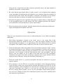
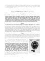
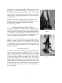
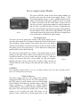
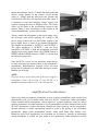
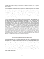
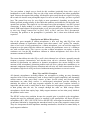
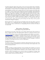
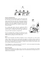
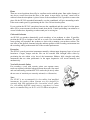
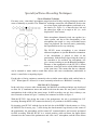
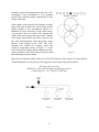
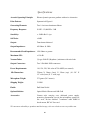
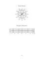
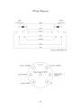
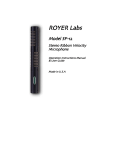
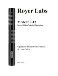
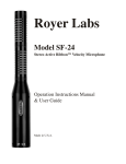
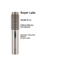
Royer Labs
Model SF-24V
Vacuum Tube, Stereo
Ribbon Velocity Microphone
Operation Instructions Manual
& User Guide
Made in U.S.A.
TABLE OF CONTENTS
Model SF-24V Ribbon Microphone
Revised 2009
Introduction
3
SF-24V Vacuum Tube Stereo Ribbon Microphone
Active & Vacuum Tube Ribbon Technology
Description
Applications
Ribbons in the Digital World
User Guide
3
3
4
4
5
5
Using the SF-24V Vacuum Tube Stereo Ribbon Microphone
Operation
Using the RSM-24 Shock Mount Accessory
5
6
7
Description
Features
Usage
Properly Inserting the Microphone into the Shock
Removing the Microphone from the Shock
Connecting the SF-24
Power Supply Input Module
7
7
7
7
8
8
9
Fuse Replacement
Voltage Changeover
9
9
Amplification Considerations
Stereo Microphones and Ground Loops
10
11
Equalization and Ribbon Microphones
Hum, Noise and Mic Orientation
12
12
Microphone Techniques
13
General Tips for Using the Royer SF-24V 13
Specialized Stereo Recording Techniques
16
Classic Blumlein Technique
Mid-Side (M-S) Technique
16
16
Care and Maintenance
18
Care for the Satin Nickel Finish
Care for the Optional Optical Black Finish
Care for the SF-24V’s African Padouk Presentation Case
Features
Specifications
Polar Pattern
Frequency Response
Wiring Diagram
Warranty
18
18
19
19
20
21
21
22
23
2
Introduction
SF-24V Vacuum Tube Stereo Ribbon Microphone
Congratulations on your purchase of a Royer Labs model SF-24V vacuum tube stereo ribbon
microphone. The SF-24V is a handcrafted precision instrument, capable of delivering superior
sound quality and exceptional performance. The SF-24V represents a new level of performance
for ribbon microphones, combining sophisticated technological advancements with old-world
craftsmanship. The SF-24V incorporates two independent head amplification systems that utilize
proven vacuum tube technology. This enables the SF-24V to deliver the same sensitivity that the
recording industry has grown accustomed to with modern condenser microphones. The
amplifying circuits are not limited by a 48-volt phantom power source, thus allowing the
SF-24V to deliver superior headroom. In addition, the electronic circuitry completely isolates
each ribbon element from impedance mismatches, short circuits and other anomalies that can
degrade microphone performance or damage the sensitive ribbon elements.
This instruction manual describes the SF-24V, its function and method of use. It also describes
the care and maintenance required to ensure proper operation and long service life. The User
Guide section of this manual offers practical information designed to maximize the performance
capabilities of this microphone.
Royer Labs products are manufactured to the highest industrial standards using only the finest
materials obtainable. Your model SF-24V went though extensive quality control checks before
leaving the factory. Normal care is all that is required to assure a lifetime of trouble-free service.
Please read this manual thoroughly in order to become familiar with all of the SF-24V’s
capabilities. It will assist you in making the most of your microphone's superior acoustic
properties. This manual is a handy reference guide and we suggest you refer to it whenever
questions arise on the use and care of your SF-24V vacuum tube ribbon microphone.
Active & Vacuum Tube Ribbon Technology
The heart of the SF-24V is its proprietary electronic system consisting of specially designed
toroidal transformers and electronic buffering stages. This system provides excellent frequency
response, extremely low noise and distortion, and high SPL handling (130 dB) without the use of
pads. It gives the SF-24V an output level comparable to that of condenser microphones, and its
buffer stages provide a low impedance output and present a perfect impedance load to each of
the ribbon elements. Standard passive ribbon microphones suffer substantially degraded
frequency response and lowered gain when they are paired to a preamp with too low an input
impedance. With the SF-24V’s active vacuum tube electronics, the microphone’s frequency
response and output are much less affected by variations in the input impedance of the following
preamp.
3
Description
The SF-24V vacuum tube stereo coincident ribbon microphone is the only microphone of its
kind available, combining high audio performance with outstanding separation and imaging. It is
a modern ribbon design, with no audible diffraction effects or cavity resonance. The SF-24V's
active electronics produce an output comparable to phantom powered studio condenser
microphones and because the ribbon elements are electronically isolated from the outside world,
the possibility of ribbons becoming damaged as a result of faulty wiring, brownouts or phantom
power supply defects is virtually eliminated.
The SF-24V is a compact, stereophonic ribbon microphone array consisting of two matched
microphone elements that are placed one above the other. Each transducer is positioned at 45º to
the left and right of center, or 90º from each other. When held vertically, connector down and the
“ROYER” logo facing the sound source, the upper transducer is OUTPUT 1 and the lower
transducer is OUTPUT 2, from the perspective of an observer behind the mic. The microphone
elements are each bidirectional (figure-8) and may be addressed from either side with equal
sensitivity. The in-phase signals are achieved when the microphone is addressed from the front,
as indicated by the “ROYER” logo. If, however, the microphone is suspended upside down, the
connections to the preamplifier should be reversed since what was the left transducer is now
responding to signals from the right and vice versa.
Your SF-24V is supplied with a dedicated power supply and 7-pin microphone interface cable.
The output for each channel consists of a chassis mounted 3-pin male XLR connector. These are
identified as OUTPUT 1 and OUTPUT 2, and correspond to the lower and upper transducers,
respectively.
The SF-24V is reasonably tolerant of shock and vibration, but care should be taken to prevent
accidental stretching of the ribbon elements due to rough handling. This is covered in the Care &
Maintenance section of this manual. The performance of the microphone is unaffected by
changes in temperature or humidity.
Applications
The SF-24V is a highly versatile microphone, ideally suited for a wide range of critical recording
applications. From drums, acoustic stringed instruments and stereo vocals to ensembles like big
band, orchestra and jazz groups, your SF-24V will capture performances with uncanny realism
and a beautifully full stereo image.
Because of the SF-24V’s coincident crossed figure-8 pattern, M-S (mid-side) recording from one
microphone is easily achievable. Once a recording has been completed using the proper
orientation, the sound field can be adjusted from pure monophonic to “super wide" or
exaggerated when compared to crossed figure-8's.
4
Although spaced microphones can produce similar stereophonic results, such recordings when
summed to mono can suffer from “comb filter” effects: peaks and dips in the frequency response.
When the SF-24V is used for M-S recording, the feeling of space changes but the sonic quality
does not. For more detailed information on the M-S technique, see the chapter Recording
Techniques: Mid-Side (M-S) Recording in this manual.
Ribbons in the Digital World
Digital recordings benefit greatly from the properties inherent in ribbon microphones. Since A to
D converters cannot distinguish between the sound source being recorded and the complex
distortion components often associated with condenser microphones, they sometimes have
difficulty tracking the signal, resulting in ringing and edgy-sounding tracks. With ribbon
microphones, ringing is almost nonexistent due to the ribbon’s lack of distortion artifacts and
high frequency peaks. A to D converters have less difficulty tracking the ribbon generated signal,
resulting in very smooth digital recordings free of microphone-related edginess.
User Guide
Using the SF-24V Vacuum Tube Stereo Ribbon Microphone
The head amplification system utilized in the SF-24V consists of two independently configured
military grade vacuum tube buffering circuits. Power for the tubes is supplied to the microphone
from a dedicated AC-line operated power supply that connects to the microphone through a 7-pin
microphone cable. The power supply provides a high voltage source and independent low
voltage sources for the vacuum tube's filaments. An electronic constant current source
automatically compensates for any change in the microphone's cable's length and provides the
correct voltage and current to each of the vacuum tube's heaters.
1. Always connect the microphone to the power supply before applying AC or turning the
supply on. Allow at least ten minutes of warm up time before using the microphone. This is
required to give ample time for the vacuum tubes elements to "settle."
2. The stereo outputs of the SF-24V are available at the power supply through a pair of male
XLR connectors. OUTPUT 1 corresponds to the upper transducer and OUTPUT 2
corresponds to the lower transducer when the mic is held vertically. Each output is
transformer isolated and fully balanced. The SF-24V’s output configuration is as follows:
Pin-1 is a shared ground for each output connector; Pin-2 is signal hot (in-phase) and Pin-3
signal cold (reverse-phase).
3. In rare instances, the common ground connection (Pin-1) between the two output connectors
can cause a ground loop. This can occur when poorly designed preamplifiers or certain types
of patch bays and/or wiring configurations are encountered. If this condition presents itself,
5
lifting the Pin-1 connection from either connector (preferably done at the input amplifier or
patch bay) will usually cure the problem.
3. Be certain that the input channel fader or volume control is set to minimum before plugging
in any microphone. Preamplifier gain trim should be set to minimum. Plug the microphone in
and activate the power switch. The microphone’s electronics will stabilize in a few minutes
but it may take up to ten minutes for optimum noise performance to be fully realized.
4. When the microphone becomes operational, bring the two channel faders to 0-dB (unity) and
use the preamplifier trims to set the desired level. This technique maximizes the signal-tonoise performance of the preamplifier or console input channel.
5. When disconnecting the microphone, bring the channel faders down then turn off the power
supply and unplug the microphone cable ends.
Operation
There are a few important facts that are key to understanding how to use ribbon microphones
intelligently.
1. With ribbon microphones, rejection in the “dead” areas is very strong. Due to this
directionality, ribbon mics should be placed at 1.3 times the distance normally used with
omni-directional microphones, or at approximately the same distance used for cardioid
microphones. This method is used to achieve the same ratio of direct to reflected sound.
2. In the horizontal plane, ribbon microphones do not discriminate against the “highs” off axis,
nor do they boost them on axis. Therefore, several instruments or vocalists can be placed in
front of the microphone without favoring the performer in the center of the group. Several
performers can be grouped at both the front and the back of the microphone, with one
proviso: since the outputs are out of phase at the front and back of the microphone,
cancellation can result if two tenors are placed on opposite sides at equal distances and are
singing in unison. Therefore, listen to the feed before committing to it.
3. The Royer model SF-24V is a powered microphone and must be connected to its power
supply to operate.
4. Never attempt to “test” the SF-24V (or any ribbon microphone) with an ohmmeter. Damage
to the electronics could occur. Always provide adequate protection for your SF-24V (or any
ribbon microphone). If the microphone is to remain set up on a stand when not in use, place a
“mic sock” (provided) over it until it is to be used. As even light wind can stretch the
SF-24V’s delicate ribbon elements, do not carry the microphone around without placing a
mic sock over it. Failure to follow this commonsense practice may yield a stretched ribbon
and compromised performance!
6
5. Avoid dropping the microphone. An accidental fall to a hard surface could stretch one or both
ribbons and, depending on the nature of the fall, possibly necessitating a complete overhaul
of the microphone.
Using the RSM-24 Shock Mount Accessory
Description
Your SF-24V is supplied with a Royer RSM-24 suspension type shock-mount accessory
designed specifically for this microphone. The RSM-24’s specially formulated polymer mounts
provide maximum isolation from shock and vibration while holding the SF- 24V securely in
place, allowing the microphone to be safely positioned at any angle. The RSM-24’s Delrin
support tubes are relieved on the inside to minimize contact with the microphone. Teflon strips
are bonded to the inside of the Delrin tubes and serve as a means to slide the microphone in and
out of the shock. It is normal for the Teflon strips to develop wear marks with repeated use.
Features
The shock-mount easily accommodates standard US microphone stand threads (5/8", 27-thread),
and an adapter is provided for European microphone stand threads. The support frame is
machined from solid T-6 hard aluminum, then black anodized for long life and a clean
unobtrusive appearance. The clutch mechanism provides easy positioning of the shock-mount
with minimal pressure. There is also a relief button that enables the clutch handle to be
repositioned out of the way. The shock mount has two orientation slots for easy X-Y and M-S
positioning. The X-Y slot faces forward and the M-S slot is 45º to the left.
Usage
It is important to use the RSM-24 shock-mount correctly. Making sure that the microphone is
inserted properly into the shock mount will minimize any chance of the mic coming loose and
will assure proper orientation of the transducer elements. It is also important to make certain that
the mic is inserted and removed gently to avoid unnecessary shock to the ribbons.
Properly Inserting the Microphone into the Shock
Examine the shock-mount carefully. Observe that the upper
Delrin support tube has one slot inside the tube that faces
forward, the same direction as the logo, and one slot that faces
45º to the left of center. The forward slot is used to orient the
center, on-axis position of the microphone. This is critical in
establishing accurate left/right (X-Y) positioning relative to the
sound source. The microphone is inserted in such a manner that
the "ROYER" logo on the microphone nestles comfortably in
this slot. The 45º left-of-center slot is used to orient the
microphone for M-S recording. With the microphone logo
inserted in this slot, the upper ribbon element faces forward for
the "Mid" signal and the lower ribbon element faces sideways
for the "Side" signal. (Figure 1)
7
Figure 1
Hold the mic by placing the transducer (ribbon element) end in
the palm of one hand. While holding the shock mount in the
other hand, gently insert the microphone's base into the upper
tube first. Be sure that the logo on the microphone aligns itself
with the slot in the upper support tube as you feed the mic
through. (Figure 2)
Continue to feed the microphone through the upper tube and
into the lower tube where it will stop when it reaches the lip at
the bottom of the lower tube. Do not force or jerk the
microphone into position!
Removing the Microphone from the Shock
Removal is simply the reverse process. Firmly grip the
microphone with one hand and gently slide it out of the shockmount. (Figure 3) It may help to gently push from the bottom of
the microphone while removing it from the lower tube. Again,
be sure not to force or jerk the microphone. Ribbon elements are
sensitive to abrupt shocks and blasts of air, so be gentle.
Figure 2
Note: If, after a time, body oils or other contaminants make it
difficult to insert or remove the microphone from the shock
mount, a small amount of talc can be used to "lubricate" the
microphone housing. Use talc very sparingly and do not let any
of it get into the ribbon transducers, as it can compromise the
ribbons’ performance.
Connecting the SF-24
The SF-24V comes with a dedicated power supply that operates
from line voltages ranging from 100-240 volts AC. A seven-pin
cable is used to power the microphone and carry the audio
signals from the microphone to the power supply. An IEC
business type three-conductor detachable line cord provides
power to the supply from an AC mains source. For voltages
configurations available outside the United States, adapters are
readily available to convert the power cord's male end to the
corresponding outlet type as needed. Before using your SF-24V,
be certain that the voltageselector/fuse block is configured for
the proper voltage.
8
Figure 3
Power Supply Input Module
Image 1
The power OFF/ON switch and the Power Input Module are
located on the rear side of the power supply (Image 1). The
Power Input Module (Image 2) serves multiple functions and is
integral to the design of the power supply. It serves as a means
to connect and remove the AC mains cable, it houses the AC
line fuses, provides a convenient method of voltage changeover,
and also serves as an RF line filter. AC power is supplied to the
unit via a removable IEC type business machine cable that plugs
into the bottom section of the Power Input Module. The power
cord must be removed to gain access to the door to change fuses
or to set the unit to a different AC input voltage.
Fuse Replacement
Two fuses are used to protect the circuitry of the power supply, one on
each side of the mains line. To inspect or replace the line fuses (necessary
when changing voltage settings), first remove the power cord. Insert a
medium size flat-blade screwdriver into the lip at the top of the module
and gently pry the door open (Image 3). Be careful not to damage the
painted surface of the chassis housing.
The fuses are located inside two carriers, each marked with an arrow
pointing to the right. These carriers can be pulled out with the tip of a
screwdriver blade or a pair of needle nose pliers (Image 4). Once the
carriers are removed, the fuses can be pulled out with your fingers.
Replacing the fuse carriers is the reverse of removal. They can only be
inserted with the arrow facing to the right and they should go in very
easily.
Image 2
CAUTION!
Never attempt to bypass a fuse or use one of a higher rating! Not only is this an unsafe practice,
but it will void the factory warranty.
Voltage Changeover
The power supply can be set to operate from voltages
ranging from 100 to 240 volts AC. For 230V operation, use
the 240V setting. A small window at the rear of the Input
Power Module will display the current voltage setting. To
change operation to a different AC voltage requires
repositioning the selector drum within the module. Remove
the power cord and open the module door in the same
manner as for accessing the fuses. The drum can be
removed with a small pair of needle-nosed pliers or the
Image 3
9
thumb and forefinger (Image 5). Rotate the drum so that the
desired voltage appears in the window of the module
(Image 6). Gently push the drum back into position and
close the door. The door will snap shut when fully closed. It
is important to note that changing voltage settings also
requires changing the fuses to different values. The correct
values can be found in the specifications section of this
manual. There is more information on this subject in the
"Power Input Module" section of this manual.
Always connect the microphone to the power supply using
the seven-pin cable before applying AC voltage to the
power supply. Connect the two XLR audio outputs of the
power supply unit to a stereo or two-channel preamplifier.
The outputs are identified as OUTPUT 1 and OUTPUT 2.
The upper transducer is OUTPUT 1 and the lower
transducer is OUTPUT 2. With the microphone positioned
upright (logo facing sound source), the UPPER element is
RIGHT and the LOWER element is LEFT, as viewed from
the observer's perspective.
Image 4
Since the SF-24 is active, its low impedance output allows
for long cable runs with minimal affect on the microphone’s
performance. High-frequency response losses and noise
pickup will be minimal even with cable runs up to severalhundred feet in length.
Image 5
NOTE:
There are no user serviceable parts in the power supply or
microphone. Leave all servicing of your SF-24V to a
qualified technician authorized to service this product.
Image 6
Amplification Considerations
Almost any stereo microphone preamplifier (or pair of mono preamplifiers) with nominal gain
characteristics will give excellent results with your SF-24V vacuum tube ribbon microphone.
Unlike standard ribbon microphones, which depend on a proper impedance match to deliver
optimal performance, the input impedance of your preamplifiers will have minimal affect on the
SF-24V’s performance because the ribbon elements are loaded perfectly via the microphones’
internal electronics. Careful consideration should be given to the quality of the microphone
preamplifier. Studio grade preamplifiers usually sound much better than cheaper ones.
Headroom, noise floor, transparency and coloration are all factors to consider in determining
which preamplifier is suitable for your studio or live applications. Other features are usually
10
secondary and fall into the category of conveniences or interface capabilities (such as digital or
optical outputs).
A good preamplifier should sound natural, with no sign of edginess or excessive noise. Vacuum
tube preamplifiers sound warm, yet wonderfully airy and transparent. Do not expect a vacuum
tube preamplifier to be as quiet as a solid-state preamp, as electron emissions from tubes tend to
convey more “thermal” noise than transistors. Tube preamplifier noise is far less of an issue with
the SF-24V than with conventional ribbon microphones because the SF-24V’s high output will
override the noise. Transformer coupled preamplifier designs tend to sound punchy and full
bodied and offer the added benefit of true electronic isolation. This greatly enhances their ability
to interface with other equipment with minimal noise or hum. There are many excellent
preamplifiers on the market today.
Choose a preamplifier that fits your budget and offers good performance, but remember that you
get what you pay for. If you have the opportunity to audition one or more preamplifiers before
you buy one, do so. Microphones and preamplifiers work together as a team and some are just
better matches than others. The SF-24V is capable of substantial output signal, especially when
used for high SPL applications like drum overheads. It will not overload or produce distortion up
to its SPL handling capacity of 130 dB SPL. In actuality, the SF-24V’s ribbons would stretch
well before the electronics would reach an overload condition. Due to the high output potential
of the SF-24V, it is recommended that the microphone preamplifier you pair it with have a
switchable pad to prevent the possibility of overloading the preamplifier’s input stage electronics.
Some preamplifiers are more thoughtfully designed than others, with a suitable pad that is placed
before the preamp’s active electronics, not incorporated into a “feedback loop” as is sometimes
found. The latter design could still produce distortion due to overloading even if the pad were
used. Although this is rarely an issue, we felt that it was important to cover the subject. In
conclusion, preamplifier coloration is optional and a matter of personal taste. Some people love
the effect of coloration while others strive for absolute transparency.
Stereo Microphones and Ground Loops
Some preamplifiers are prone to developing ground loops when used in conjunction with stereo
microphones such as the SF-24V. Ground loops can develop in the preamplifier with any stereo
microphone regardless of type (i.e. condenser, dynamic, ribbon) or brand. A ground loop
manifests itself as unwanted buzz or hum at 60 Hz and/or harmonics of 60 Hz.
The condition is brought on when the left and right transducer elements are plugged into two
inputs of a stereo or multi-channel preamplifier. The two male, three-pin XLR connectors of a
stereo microphone's cable (or power supply in the case of the SF-24V) usually share Pin-1 as
common, so they are grounded to each other at the microphone or power supply. If the grounding
scheme within the preamplifier is poorly designed, or the distances to internal ground are too
great, a ground loop develops.
11
You can perform a simple test to check for this condition (preferably done with a pair of
headphones to avoid feedback). Plug one side of the stereo microphone into either preamplifier
input. Listen to the output of the preamp. All should be quiet except for the mic signal. Now plug
the second side into the next preamplifier input. If a noise or buzz develops, you have a ground
loop. The ground loop may be very slight or more pronounced, depending on the preamp.
Battery powered preamps usually do not exhibit this problem, and neither do well designed, lineoperated mic preamps. The simple fix is to disconnect one of the microphone’s two Pin-1 ground
connections. A better method is to make a small ground-lift adapter fashioned from a malefemale XLR barrel adapter. Switchcraft makes a very nice one and it takes less than five minutes
to wire it up. Simply connect Pin-2 to Pin-2, Pin-3 to Pin-3, and leave Pin-1 disconnected.
Correcting the problem at the preamplifier is preferable, but is often more difficult and/or
expensive.
Equalization and Ribbon Microphones
One of the great strengths of ribbon microphones is how well they take EQ. Even with
substantial amounts of equalization, ribbons retain their natural, “real” quality. For example,
when a lead vocal is being performed on a ribbon microphone, you can boost the upper-end
frequencies to the point where the ribbon mic emulates the performance curve of a condenser
mic with excellent results. This is not to say that a ribbon microphone can replace a quality
condenser mic, but the EQ friendliness inherent in ribbon microphones does allow for an
enormous amount of flexibility.
The reason that ribbon mics take EQ so well is their inherent low self-noise, unusually smooth
frequency response characteristics and freedom from off-axis coloration. Dialing in high
amounts of equalization on condenser or dynamic microphones also means dialing in extra
amounts of the microphone's distortion products and self noise: garbage that contributes to an
unnatural, unpleasant sound. Because distortion and self-noise are almost nonexistent in ribbon
microphones, high levels of EQ can be used without incurring harshness or excessive noise.
Hum, Noise and Mic Orientation
All dynamic microphones, including ribbons, are susceptible to picking up stray alternating
magnetic fields. Power transformers (such as those found in guitar amplifiers) and alternating
current motors are the most likely sources of hum. In-wall wiring and electrical utility
transformers are other likely sources. A well-designed microphone provides shielding to
minimize the effects of such stray magnetic radiation. In some cases complete isolation is
impossible and the result is usually hum or buzz. Unpowered microphones are more susceptible
to hum pickup after the mic, for example through the cable set. With vintage ribbon
microphones, which often employ large, bulky magnet structures and are often poorly shielded,
the problem can be worse.
The SF-24V reduces this condition because the essential gain is provided at the microphone,
negating the need for additional gain to be supplied by the preamplifier. All Royer SF-series
microphones (SF-1, SF-12, SF-24, SF-24 Live and SF-24V) are designed to minimize the effects
of unwanted radiation by integrating the transducer barrel as part of the magnetic return circuit.
They also incorporate toroidal impedance matching transformers, which have a natural ability to
repel magnetic radiation.
12
Unwanted magnetically induced noise (hum) can only come from external sources. Fortunately,
simply repositioning a ribbon microphone often gets rid of unwanted noise. If hum is detected,
the microphone is in the proximity of an alternating magnetic field. While listening (preferably
with headphones) to the mic, move it around. The mic will “find” the noise source quite easily.
For example, if you are miking a guitar amplifier and suspect the amplifier’s power transformer
may be the source of hum, move the mic around the amp. You will probably find that the hum is
louder as you approach the amplifier’s power supply and quieter when you move it away.
Eliminating the hum can be fairly simple and requires finding the “null” point of the hum. The
“null” point is the position that places the microphone’s magnetic components away from the
lines of the noise's radiation. Slightly rotating the microphone is usually all that is required to
cancel out the hum. This is similar to the procedure guitarists use to eliminate hum from single
coil guitar pickups: turning around slowly while listening for the hum. There will be a position
where the hum disappears completely.
Hum and other noises are often picked up in microphone cables. Since the output of a powered
Royer ribbon is 15 to 25 dB higher than with a traditional unpowered ribbon microphone, any
noise picked up in the mic cable will be at a corresponding lower level, and hence less likely to
be objectionable.
Microphone Techniques
General Tips for Using the Royer SF-24V
The following are good basic starting places for recording with the SF-24V. These positions are
known to produce good results, but experimentation is the key to getting the most out of your
recordings! Photographs of many of the following techniques can be found on our website -www.royerlabs.com. It is important to remember that the SF-24V’s ribbon elements can be
damaged by wind. When the SF-24V is mounted on a boom stand, be sure the stand is moved
slowly. When the microphone is taken down, put it in its box immediately or, if it is to remain in
its shock mount, place the mic sock over the transducer end of the microphone. Leaving the
microphone out and unprotected invites an early re-ribboning job.
Ensemble Performances
The SF-24V records ensemble performances beautifully. Simply find the point in the room where
you hear the best blend of the instruments and room sound and place the microphone there, with
its logo facing the performers.
Strings
For stereo recordings of stringed instruments, start by positioning the microphone a few feet off
the body of the instrument. Depending on the acoustics of the room, you may want to move the
microphone closer to or further from the instrument to add or minimize ambience. For violin,
position the SF-24V horizontally, two or more feet above the instrument. For larger string
sections, try placing the microphone slightly above the instrumentalists and angled down; a
distance of three or four feet will do the job nicely.
13
Drum Overhead & Room
Position the SF-24V horizontally over the center point of the
kit, two to three feet above the cymbals. For a centered snare
drum, aim the Royer logo at the snare. Adjusting the height of
the SF-24V by even 6-inch increments will produce dramatic
variations in how the cymbals sit with the rest of the kit.
Many times an overhead SF-24V is all that is needed for tomtoms and cymbals.
For a single point stereo room mic, position the SF-24
vertically at four to eight feet in front of the kit. Compress to
taste for either a very natural drum sound (light compression)
or large rock drum sound (heavy compression).
For jazz recordings, EQ is generally not required. For more
aggressive drum tracks where cymbals need to sizzle, you can
brighten them by adding a few dB of 10K to 12K.
Brass
Brass records beautifully with ribbon microphones. For an overall picture of a brass section
within a larger recording session, try placing the microphone at a distance of three to eight feet
from the section, two to three feet above the instrumentalists and angled downward. For a solo
brass section, position the SF- 24V vertically at a height of four to eight feet and anywhere from
five to twenty or more feet from the section.
Close miking brass is a job for the Royer R-121 or R-122 -- we do not recommend close-miking
with the SF 24V or any SF-series microphone.
Reed Instruments
Normal working distances are about a foot or two from a solo reed instrument. For multiple
instruments, try placing the microphone slightly above the instrumentalists and angled down, at a
distance of two to four feet.
14
Piano
There are several positions that will give excellent results with the piano. Start with a distance of
one foot to several feet from the knee of the piano. A more direct “up front” sound will be
achieved when the microphone is placed closer to the soundboard. If it is possible to remove the
piano lid, the SF-24V suspended horizontally over the soundboard will give outstanding results.
If the room sounds good, try positioning the mic 10 to 20 feet from the piano.
If you position the SF-24V somewhere between the soundboard and the open lid of the piano,
there will be some amount of reflected sound from the lid. Careful positioning can minimize or
accent lid reflections, depending on what sound you’re striving for.
Choir and Orchestra
An SF-24V can produce dramatically good recordings of an orchestra or choir. If possible,
position the SF-24 at a height of ten feet or so and a few feet behind the conductor. The wide
stereo pickup will reproduce the orchestra or choir with a stunning you-are-there realism. The
rear lobes of the figure-8 elements bring the ambient qualities of the recording environment into
the recording, adding to the natural feel of the recorded performance.
Percussion
The SF-24V records percussion instruments naturally, without upper frequency hype or low-end
boominess. Congas, bongos and the like can be recorded with left/right stereo effect by
positioning the mic within a few feet of the instruments. Shakers, bells, triangles and other
instruments that are often problematic in the upper frequencies will record naturally and
unobtrusively.
Vocal with Acoustic Guitar
For recording a vocal with acoustic guitar, two separate mono
tracks are required with little leakage between the tracks. One stand
and one horizontally positioned SF-24V can do the job nicely when
the two axes of sensitivity are correctly oriented (see illustration).
Note:
The SF-24V is not recommended for close-miking loud amplified
instruments. Its sensitive ribbon elements were not designed for
extremely high SPL applications like close-miked electric guitar.
For close-miking high SPL sound sources, ruggedness is a must
and we recommend using our R-121 or R-122 ribbon microphones.
15
Specialized Stereo Recording Techniques
Classic Blumlein Technique
For many years, “coincident” microphone setups have been widely used for picking up sounds in
stereo as naturally as possible. The “Blumlein” technique, named for A.D. Blumlein, involves the
use of two figure-eight microphones positioned as in
the sketch (see Figure 1); so that one faces left and
the other faces right, at an angle of 90º (i.e., each
displaced 45º from center).
Each microphone ultimately feeds one speaker in a
stereo system, and due to the directionality of the
microphones, the result is a very well defined stereo
image on playback. For classical music, particularly,
the reproduction can be very satisfying.
The SF-24V stereo microphone is two identical
ribbon microphones in just this Blumlein orientation:
if the microphone is placed in front of the
performance, with the Royer logo facing the center of
the ensemble to be recorded, the microphone will
give a stereo recording as per the Blumlein technique.
Because of the togetherness of the SF-24V’s ribbon
Figure 1
transducers, sound will arrive at both ribbon elements
at the same time. This means that the two channels
can be summed to mono with no comb filter effects, and room reverberation (undesirable in
mono) is cancelled to a surprising degree.
For the sake of clarity, engineers commonly refer to similar stereo miking with cardioid mics as
“X-Y.” When figure-8’s are used, it is more commonly referred to as “Blumlein” recording.
Mid-Side (M-S) Technique
In the early days of stereo radio broadcasting, the Mid-Side recording technique was developed
to allow for 1) simultaneous stereo and mono feeds from the same mic array and 2) electronic
manipulation of the width of the stereo image. In M-S recording, one mic faces sideways, one
faces forward as shown in Figure 2, and they are connected as shown in Figure 3.
With the SF-24V's logo facing the center of the performance, the mic is positioned for X-Y
recording. Rotating the SF-24V counter-clockwise by 45º positions it for MS recording.
By inserting your SF-24V with the logo in the left slot of the RSM-24 shock mount (see Using
the RSM-24 Shock-mount, page 7), then facing the shock-mount's logo directly at the center of
the performance, the microphone will be rotated 45º counterclockwise and correctly positioned
for M-S recording. With the SF-24V in a vertical position, cable end down, the upper ribbon
element faces the center of the performance and is the “mid” microphone, and the lower ribbon
16
element is at 90º to the performance and is the “side”
microphone. If the microphone is to be mounted
upside down, make the proper adjustments in your
wiring orientation.
If the outputs of the mid and side elements are made
equal using gain controls, the stereo pickup will be
similar to that of two microphones placed as a
Blumlein X-Y pair, delivering a wide stereo image.
As you reduce the level of the “side” element, the
width of the stereo image will narrow until, with the
side element turned all the way down, you have just
the “mid” element panned center and giving a mono
pickup. If the outputs of the “mid” and “side”
elements are recorded on separate tracks, the
electrical connections shown in Figure 3 can be
made at the mixer outputs and the adjustment of the
stereo separation can be done during mixdown, rather
than during the actual recording.
Figure 2
Space does not permit a fuller discussion of the M-S intensity stereo format, first described by
Alan D. Blumlein over 50 years ago. We suggest the following reading on the subject:
W. Dooley & R. Streicher
“M-S Stereo: A Powerful Technique for Working in Stereo”
J. Audio Eng. Soc., Vol. 30 pp.707 (1982 Oct.)
Figure 3
17
Care and Maintenance
The SF-24V is a solidly built, precision instrument. Following a few commonsense rules is all
that is required to ensure proper operation of this microphone.
1. To avoid transducer damage, do not expose the microphone to severe shock or vibration. If
the microphone is accidentally dropped, test it to see if damage has occurred before returning
it to service. Low output or a dull sound in one or both transducers would indicate a stretched
ribbon.
2. Do not expose the microphone to direct blasts of air or strong air currents. Use a windscreen
or suitable blast filter when close miking a vocalist or certain types of wind instruments. Ppopping does not necessarily damage the ribbon element, but it may produce unacceptable
preamplifier overload and could cause damage to speaker systems.
3. Do not expose the microphone to liquids or caustic smoke.
4. Do not expose the microphone to strong alternating electromagnetic fields, i.e. the power
transformers in amplifiers, or a hum may result.
5. Use a soft cloth to clean the microphone body. A small amount of denatured alcohol can be
used to remove fingerprints and other stains. Use WD-40® or mineral oil to protect the finish.
6. Keep metal filings away from the microphone at all times. The SF-24V's powerful magnets
can attract minute ferrous particles into the ribbon transducers, compromising the
performance.
7. When not in use, store the microphone in its protective carrying case. If the microphone is to
remain set up on a mic stand between sessions, cover it with its mic sock (provided with your
SF-24V).
8. Leave disassembly of the microphone to a trained technician. There are no user-serviceable
parts inside the microphone or power supply.
Care for the Satin Nickel Finish
The SF-24V’s standard dull satin nickel finish is durable and easy to maintain. Simply use a soft
cloth to clean the microphone body. If needed, a small amount of denatured alcohol can be used
to remove fingerprints and other stains. Care for the Optional Optical Black Finish
The SF-24V's optional optical black finish is a surface treatment designed to refract light rather
than reflect it. To maintain the finish, it is good practice to massage the microphone gently with a
lint free cloth treated with a few drops of light machine oil or WD-40® (apply the oil to the
18
cloth, not to the microphone). Be very careful whenever working around the transducers to avoid
contamination of the ribbon elements.
Care for the SF-24V’s African Padouk Presentation Case
The SF-24V’s handcrafted presentation case is milled from two matching pieces of African
Padouk. To best protect the case, minimize direct and prolonged exposure to sunlight, heat, and
moisture. As the case ages, it will take on a darker, more lustrous hue. To maintain and beautify
the case’s finish, we suggest wiping it with a thin coat of boiled linseed oil or Tung oil (available
at most home improvement stores) once a year. Use the oil sparingly and apply with a soft cloth.
Paste wax may also be used for a high luster finish.
CAUTION!
Due to the transducer’s powerful magnets, keep recorded tapes, spring-wound watches and
personal credit cards with magnetic coding away from the microphone to prevent possible
damage.
Features
•
Excellent stereo imaging and separation in one microphone
•
Smooth, wide frequency response
•
Vacuum Tube electronics offer greatly enhanced output and a constant, optimized impedance
to the ribbon element
•
X-Y, M-S, or mono recording from one microphone
•
Extremely low residual noise
•
Ribbon elements are unaffected by heat or humidity
•
Absence of high-frequency phase distortion
•
Excellent phase linearity – even off axis
•
Equal sensitivity from front or back of microphone
•
Consistent frequency response regardless of distance
•
Compact size
19
Specifications
Acoustic Operating Principle: Electro-dynamic pressure gradient with active electronics
Polar Pattern: Symmetrical Figure-8
Generating Elements: Two 1.8-micron aluminum ribbons
Frequency Response: 30 HZ – 15,000 HZ ± 3 dB
Sensitivity:
> -38dBv Ref 1 v/pa
Self Noise: <18dB
Output:
Transformer balanced
Output Impedance: 450 Ohms @ 1kHz
Recommended Load Impedance: 1500 Ohms or greater
Maximum SPL: > 130 dB
Vacuum Tubes:
(2) type 5840-W (Raytheon ) miniature with wire leads
Output Connectors: Two 3-Pin Male XLR connectors
Power Requirements: 110, 120, 220, 240-volts AC 50-60HZ (see manual)
Mic Dimensions: 270mm X 39mm (base) X 25mm (top) (10 5/8" X
1.5" wide (base) X 1" wide (top)
Microphone Weight: 572 grams (20.2 ounces)
Shipping Weight: 21 LBS
Finish: Dull Satin Nickel
Optional finishes: Optical Black Chrome and 18K Gold
Accessories: Camera style carrying case, dedicated power supply,
protective presentation case for the microphone, protective
mic sock, 20-foot shielded 7-conductor cable RSM-24
shock mount, IEC AC-line cord.
To learn more about Royer products and their usage, visit our website at www.royerlabs.com.
20
Polar Pattern
Frequency Response
21
Wiring Diagram
22
Warranty
PLEASE RETAIN YOUR ORIGINAL BILL OF SALE AS YOU WILL NEED TO PRESENT IT
SHOULD YOU REQUIRE SERVICE UNDER THIS WARRANTY.
TO VALIDATE THIS WARRANTY, THE REGISTRATION CARD AND A PHOTOCOPY OF THE
SALES RECEIPT FROM AN AUTHORIZED ROYER DEALER MUST BE ON FILE WITH ROYER
LABS.
Royer Labs hereby warrants all Royer SF-series microphones with the following terms and conditions.
WARRANTY PERIOD
Body fit and finish
Lifetime
Transducer frames/magnets Lifetime
Transformers
Lifetime
Vacuum Tube 10 years Parts and Labor
Cables & Cable Sets
2 years Parts and Labor
Shock Mount Accessories
2 years Parts and Labor
Ribbon Element
1 year Parts and Labor
SCOPE OF WARRANTY:
From the date of original purchase and for the respective periods specified above, Royer Labs agrees to
repair, at its sole expense, all Royer Labs products which are defective in material and workmanship.
EXCLUSIONS:
This warranty does not cover the following:
1.
Defects or damage caused by accident, fire, flood, lightning or other acts of nature.
2.
Defects or damage caused by abuse, misuse, negligence or failure to observe the instructions
contained in the owner’s manual furnished at the time of original purchase.
3.
Damage caused during shipping or handling.
4.
Products that have had their serial numbers altered or removed.
5.
Products purchased in “AS-IS” (used) condition.
6.
Products that have been altered or repaired by anyone other than a factory authorized service station.
ROYER Labs
2711 Empire Ave.
Burbank, California 91504
Telephone 818.847.0121
Fax 818.847.0122
www.royerlabs.com
23