1
Management
Software
AT-S63
◆
Menus
User’s Guide
For Stand-alone AT-9400 Switches
Version 2.2.0 for AT-9400 Layer 2+ Switches
Version 3.2.0 for AT-9400 Basic Layer 3 Switches
613-001025 Rev. A
Copyright © 2008 Allied Telesis, Inc.
All rights reserved. No part of this publication may be reproduced without prior written permission from Allied Telesis, Inc.
Microsoft and Internet Explorer are registered trademarks of Microsoft Corporation. Netscape Navigator is a registered trademark of
Netscape Communications Corporation. All other product names, company names, logos or other designations mentioned herein are
trademarks or registered trademarks of their respective owners.
Allied Telesis, Inc. reserves the right to make changes in specifications and other information contained in this document without prior
written notice. The information provided herein is subject to change without notice. In no event shall Allied Telesis, Inc. be liable for any
incidental, special, indirect, or consequential damages whatsoever, including but not limited to lost profits, arising out of or related to this
manual or the information contained herein, even if Allied Telesis, Inc. has been advised of, known, or should have known, the possibility of
such damages.
Contents
Preface ............................................................................................................................................................ 19
How This Guide is Organized........................................................................................................................... 20
Product Documentation .................................................................................................................................... 22
Where to Go First ............................................................................................................................................. 23
Starting a Management Session ...................................................................................................................... 24
Document Conventions .................................................................................................................................... 25
Where to Find Web-based Guides ................................................................................................................... 26
Contacting Allied Telesis .................................................................................................................................. 27
Online Support ........................................................................................................................................... 27
Email and Telephone Support.................................................................................................................... 27
Returning Products .................................................................................................................................... 27
Sales and Corporate Information ............................................................................................................... 27
Management Software Updates................................................................................................................. 27
Section I: Basic Operations ...................................................................................... 29
Chapter 1: Basic Switch Parameters ........................................................................................................... 31
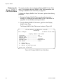
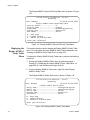
Configuring the Switch’s Name, Location, and Contact ................................................................................... 32
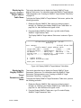
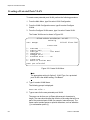
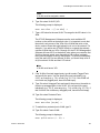
Changing the Manager and Operator Passwords ............................................................................................ 35
Changing the Manager or Operator Password .......................................................................................... 35
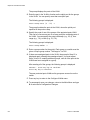
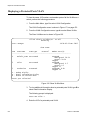
Resetting the Manager Password .............................................................................................................. 37
Setting the System Time .................................................................................................................................. 38
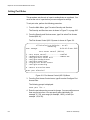
Setting the System Time Manually............................................................................................................. 39
Setting the System Time from an SNTP or NTP Server ............................................................................ 40
Rebooting the Switch........................................................................................................................................ 43
Configuring the Console Startup Mode ............................................................................................................ 45
Configuring the Console Timer......................................................................................................................... 46
Configuring the Telnet Server........................................................................................................................... 47
Setting the Baud Rate of the Serial Terminal Port............................................................................................ 48
Pinging a Remote System ................................................................................................................................ 49
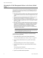
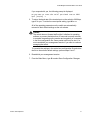
Returning the AT-S63 Management Software to the Factory Default Values .................................................. 50
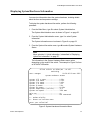
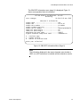
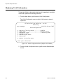
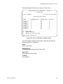
Displaying Hardware and Software Information ............................................................................................... 52
Displaying System Hardware Information ........................................................................................................ 55
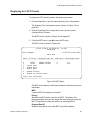
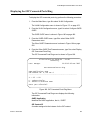
Displaying Uplink Port Information ................................................................................................................... 57
Chapter 2: Port Parameters .......................................................................................................................... 61
Displaying Port Status ...................................................................................................................................... 62
Configuring Port Parameters ............................................................................................................................ 65
Configuring Head of Line Blocking ................................................................................................................... 69
Configuring Flow Control and Back Pressure................................................................................................... 71
Configuring Port Filtering.................................................................................................................................. 73
Setting Up Rate Limiting................................................................................................................................... 75
Resetting a Port................................................................................................................................................ 77
Forcing Port Renegotiation............................................................................................................................... 78
Resetting the Port Configuration to the Default Settings .................................................................................. 79
3
Contents
Displaying Port Statistics .................................................................................................................................. 80
Clearing Port Statistics...................................................................................................................................... 83
Chapter 3: Enhanced Stacking ..................................................................................................................... 85
Setting a Switch’s Enhanced Stacking Status .................................................................................................. 86
Selecting a Switch in an Enhanced Stack......................................................................................................... 88
Returning to the Master Switch ......................................................................................................................... 91
Displaying the Enhanced Stacking Status ........................................................................................................ 92
Chapter 4: SNMPv1 and SNMPv2c ............................................................................................................... 93
Enabling or Disabling SNMP Management....................................................................................................... 94
Setting the Authentication Failure Trap............................................................................................................. 95
Creating an SNMP Community String .............................................................................................................. 96
Modifying a Community String .......................................................................................................................... 99
Deleting a Community String ..........................................................................................................................103
Displaying the SNMP Community Strings.......................................................................................................104
Chapter 5: MAC Address Table ..................................................................................................................105
Displaying the MAC Address Tables ..............................................................................................................106
Adding Static Unicast and Multicast MAC Addresses.....................................................................................110
Deleting Unicast and Multicast MAC Addresses.............................................................................................112
Deleting All Dynamic MAC Addresses ............................................................................................................113
Changing the Aging Time ...............................................................................................................................114
Chapter 6: Static Port Trunks .....................................................................................................................115
Creating a Static Port Trunk............................................................................................................................116
Modifying a Static Port Trunk ..........................................................................................................................120
Deleting a Static Port Trunk ............................................................................................................................123
Chapter 7: LACP Port Trunks .....................................................................................................................125
Enabling or Disabling LACP............................................................................................................................126
Setting the LACP System Priority ...................................................................................................................128
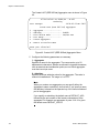
Creating an Aggregator...................................................................................................................................129
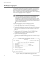
Modifying an Aggregator .................................................................................................................................132
Deleting an Aggregator ...................................................................................................................................134
Displaying LACP Port and Aggregator Status ................................................................................................135
Chapter 8: Port Mirroring ............................................................................................................................137
Creating a Port Mirror .....................................................................................................................................138
Disabling a Port Mirror ....................................................................................................................................140
Modifying a Port Mirror....................................................................................................................................141
Displaying the Port Mirror ...............................................................................................................................142
Section II: Advanced Operations ...........................................................................143
Chapter 9: File System ................................................................................................................................145
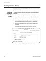
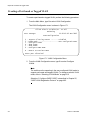
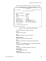
Working with Boot Configuration Files ............................................................................................................146
Creating a Boot Configuration File ...........................................................................................................146
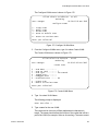
Setting the Active Boot Configuration File ................................................................................................149
Viewing a Boot Configuration File ............................................................................................................151
Editing a Boot Configuration File ..............................................................................................................152
Copying a System File ....................................................................................................................................154
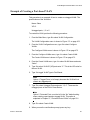
Examples..................................................................................................................................................155
Renaming a System File .................................................................................................................................156
Examples..................................................................................................................................................157
Deleting a System File ....................................................................................................................................158
Displaying System Files ..................................................................................................................................159
4
AT-S63 Management Software Menus User’s Guide
Listing All Files ......................................................................................................................................... 159
Listing Files on the Compact Flash Card ................................................................................................. 161
Working with Flash Memory ........................................................................................................................... 162
Displaying Information about the Flash Memory...................................................................................... 162
Formatting the Flash Memory .................................................................................................................. 163
Working with the Compact Flash Card ........................................................................................................... 164
Displaying Compact Flash Card Information............................................................................................ 164
Changing the Current Flash Card Directory............................................................................................. 166
Chapter 10: File Downloads and Uploads ................................................................................................. 167
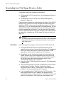
Downloading the AT-S63 Image File onto a Switch ....................................................................................... 168
Guidelines ................................................................................................................................................ 168
Downloading the AT-S63 Image from a Local Management Session...................................................... 170
Downloading the AT-S63 Image from a Remote Management Session.................................................. 174
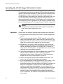
Uploading the AT-S63 Image File Switch to Switch ....................................................................................... 176
Guidelines ................................................................................................................................................ 176
Uploading an AT-S63 Configuration File Switch to Switch............................................................................. 179
Guidelines ................................................................................................................................................ 179
Downloading a System File ............................................................................................................................ 182
Guidelines ................................................................................................................................................ 182
Downloading a System File from a Local Management Session ............................................................. 184
Downloading a System File from a Remote Management Session ......................................................... 187
Uploading a System File................................................................................................................................. 190
Guidelines ................................................................................................................................................ 190
Uploading a System File from a Local Management Session.................................................................. 191
Uploading a System File from a Remote Management Session.............................................................. 194
Chapter 11: Event Logs and the Syslog Client ......................................................................................... 197
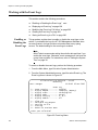
Working with the Event Logs .......................................................................................................................... 198
Enabling or Disabling the Event Logs ...................................................................................................... 198
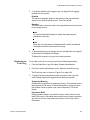
Displaying an Event Log .......................................................................................................................... 199
Modifying the Event Log Full Action......................................................................................................... 205
Clearing an Event Log.............................................................................................................................. 206
Saving an Event Log to a File .................................................................................................................. 206
Configuring Log Outputs................................................................................................................................. 209
Creating a Log Output Definition.............................................................................................................. 210
Modifying a Log Output ............................................................................................................................ 215
Deleting a Log Output .............................................................................................................................. 216
Displaying the Log Output Definition Details............................................................................................ 217
Chapter 12: Classifiers ................................................................................................................................ 219
Creating a Classifier ....................................................................................................................................... 220
Modifying a Classifier ..................................................................................................................................... 224
Deleting a Classifier........................................................................................................................................ 226
Deleting All Classifiers.................................................................................................................................... 227
Displaying Classifiers ..................................................................................................................................... 228
Chapter 13: Access Control Lists .............................................................................................................. 231
Creating an ACL ............................................................................................................................................. 232
Modifying an ACL ........................................................................................................................................... 235
Deleting an ACL ............................................................................................................................................. 237
Deleting All ACLs............................................................................................................................................ 239
Displaying ACLs ............................................................................................................................................. 240
5
Contents
Chapter 14: Class of Service ......................................................................................................................243
Configuring CoS..............................................................................................................................................244
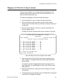
Mapping CoS Priorities to Egress Queues .....................................................................................................247
Configuring Egress Scheduling.......................................................................................................................248
Displaying Port CoS Priorities .........................................................................................................................250
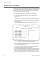
Chapter 15: Quality of Service ....................................................................................................................251
Managing Flow Groups ...................................................................................................................................252
Creating a Flow Group .............................................................................................................................252
Modifying a Flow Group............................................................................................................................255
Deleting a Flow Group..............................................................................................................................256
Displaying Flow Groups............................................................................................................................257
Managing Traffic Classes ...............................................................................................................................261
Creating a Traffic Class ............................................................................................................................261
Modifying a Traffic Class ..........................................................................................................................265
Deleting a Traffic Class ............................................................................................................................267
Displaying Traffic Classes ........................................................................................................................268
Managing Policies ...........................................................................................................................................271
Creating a Policy ......................................................................................................................................271
Modifying a Policy.....................................................................................................................................274
Deleting a Policy.......................................................................................................................................275
Displaying Policies....................................................................................................................................276
Chapter 16: Denial of Service Defenses ....................................................................................................279
Configuring Denial of Service Defense ...........................................................................................................280
Chapter 17: Power Over Ethernet ...............................................................................................................283
Setting the PoE Threshold ..............................................................................................................................284
Configuring PoE Port Settings ........................................................................................................................286
Displaying PoE Status and Settings ...............................................................................................................288
Section III: IGMP Snooping, MLD Snooping, and RRP Snooping ....................293
Chapter 18: IGMP Snooping .......................................................................................................................295
Configuring IGMP Snooping ...........................................................................................................................296
Enabling or Disabling IGMP Snooping............................................................................................................300
Displaying a List of Host Nodes ......................................................................................................................301
Displaying a List of Multicast Routers .............................................................................................................303
Chapter 19: MLD Snooping .........................................................................................................................305
Configuring MLD Snooping .............................................................................................................................306
Enabling or Disabling MLD Snooping .............................................................................................................309
Displaying a List of Host Nodes ......................................................................................................................310
Displaying a List of Multicast Routers .............................................................................................................312
Chapter 20: RRP Snooping .........................................................................................................................315
Enabling or Disabling RRP Snooping .............................................................................................................316
Section IV: SNMPv3 ................................................................................................317
Chapter 21: SNMPv3 ....................................................................................................................................319
Configuring SNMPv3 Entities..........................................................................................................................320
Configuring the SNMPv3 User Table ..............................................................................................................321
Creating an SNMPv3 User Table Entry....................................................................................................321
Deleting an SNMPv3 User Table Entry ....................................................................................................325
Modifying an SNMPv3 User Table Entry ..................................................................................................326
6
AT-S63 Management Software Menus User’s Guide
Configuring the SNMPv3 View Table ............................................................................................................. 331
Creating an SNMPv3 View Table Entry ................................................................................................... 331
Deleting an SNMPv3 View Table Entry.................................................................................................... 334
Modifying an SNMPv3 View Table Entry ................................................................................................. 335
Configuring the SNMPv3 Access Table ......................................................................................................... 340
Creating an SNMPv3 Access Table Entry ............................................................................................... 340
Deleting an SNMPv3 Access Table Entry................................................................................................ 344
Modifying an SNMPv3 Access Table Entry.............................................................................................. 346
Configuring the SNMPv3 SecurityToGroup Table.......................................................................................... 356
Creating an SNMPv3 SecurityToGroup Table Entry................................................................................ 356
Deleting an SNMPv3 SecurityToGroup Table Entry ................................................................................ 359
Modifying an SNMPv3 SecurityToGroup Table Entry .............................................................................. 360
Configuring the SNMPv3 Notify Table............................................................................................................ 364
Creating an SNMPv3 Notify Table Entry.................................................................................................. 364
Deleting an SNMPv3 Notify Table Entry .................................................................................................. 366
Modifying an SNMPv3 Notify Table Entry ................................................................................................ 367
Configuring the SNMPv3 Target Address Table ............................................................................................ 372
Creating an SNMPv3 Target Address Table Entry .................................................................................. 372
Deleting an SNMPv3 Target Address Table Entry................................................................................... 375
Modifying an SNMPv3 Target Address Table Entry................................................................................. 376
Configuring the SNMPv3 Target Parameters Table ....................................................................................... 385
Creating an SNMPv3 Target Parameters Table Entry ............................................................................. 386
Deleting an SNMPv3 Target Parameters Table Entry ............................................................................. 389
Modifying an SNMPv3 Target Parameters Table Entry ........................................................................... 390
Configuring the SNMPv3 Community Table................................................................................................... 398
Creating an SNMPv3 Community Table Entry......................................................................................... 399
Deleting an SNMPv3 Community Table Entry ......................................................................................... 402
Modifying an SNMPv3 Community Table Entry ....................................................................................... 403
Displaying SNMPv3 Table Menus .................................................................................................................. 408
Displaying the Display SNMPv3 User Table Menu .................................................................................. 408
Displaying the Display SNMPv3 View Table Menu.................................................................................. 410
Displaying the Display SNMPv3 Access Table Menu .............................................................................. 411
Displaying the Display SNMPv3 SecurityToGroup Table Menu .............................................................. 411
Displaying the Display SNMPv3 Notify Table Menu ................................................................................ 412
Displaying the Display SNMPv3 Target Address Table Menu ................................................................. 413
Displaying the Display SNMPv3 Target Parameters Table Menu............................................................ 413
Displaying the Display SNMPv3 Community Table Menu ....................................................................... 414
Section V: Spanning Tree Protocols ...................................................................... 417
Chapter 22: Spanning Tree and Rapid Spanning Tree Protocols ........................................................... 419
Enabling or Disabling a Spanning Tree Protocol............................................................................................ 420
Configuring STP ............................................................................................................................................. 422
Configuring STP Bridge Settings ............................................................................................................. 422
Configuring STP Port Settings ................................................................................................................. 425
Displaying STP Port Settings ................................................................................................................... 428
Resetting STP to the Default Settings...................................................................................................... 429
Configuring RSTP........................................................................................................................................... 430
Configuring RSTP Bridge Settings........................................................................................................... 430
Configuring RSTP Port Settings............................................................................................................... 433
Displaying the RSTP Port Configuration .................................................................................................. 435
Displaying the RSTP Port State ............................................................................................................... 437
Resetting RSTP to the Default Settings ................................................................................................... 438
7
Contents
Chapter 23: Multiple Spanning Tree Protocol ...........................................................................................439
Selecting MSTP as the Active Spanning Tree Protocol ..................................................................................440
Configuring MSTP Bridge Settings .................................................................................................................441
Configuring the CIST Priority ..........................................................................................................................445
Displaying the CIST Priority ............................................................................................................................447
Creating, Deleting, and Modifying MSTI IDs ...................................................................................................449
Creating an MSTI ID.................................................................................................................................449
Deleting an MSTI ID .................................................................................................................................450
Modifying an MSTI ID ...............................................................................................................................450
Adding, Removing, and Modifying VLAN Associations to MSTI IDs...............................................................452
Adding or Removing a VLAN from an MSTI ID ........................................................................................452
Associating a VLAN to an MSTI ID...........................................................................................................453
Removing a VLAN from an MSTI ID.........................................................................................................454
Associating VLANs to an MSTI ID and Deleting All Associated VLANs...................................................455
Clearing VLAN to MSTI Associations .......................................................................................................456
Configuring MSTP Port Settings .....................................................................................................................457
Configuring Generic MSTP Port Settings .................................................................................................457
Configuring MSTI-specific Port Parameters .............................................................................................460
Displaying the MSTP Port Configuration ........................................................................................................463
Displaying the MSTP Port State .....................................................................................................................465
Resetting MSTP to the Defaults......................................................................................................................468
Section VI: Virtual LANs .......................................................................................469
Chapter 24: Port-based and Tagged VLANs ..............................................................................................471
Creating a Port-based or Tagged VLAN .........................................................................................................472
Example of Creating a Port-based VLAN .......................................................................................................477
Example of Creating a Tagged VLAN .............................................................................................................479
Modifying a Port-based or Tagged VLAN .......................................................................................................481
Displaying VLANs ...........................................................................................................................................485
Deleting a Port-based or Tagged VLAN .........................................................................................................487
Deleting All VLANs..........................................................................................................................................490
Displaying PVIDs ............................................................................................................................................492
Enabling or Disabling Ingress Filtering ...........................................................................................................493
Chapter 25: GARP VLAN Registration Protocol ........................................................................................495
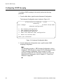
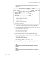
Configuring GVRP ..........................................................................................................................................496
Enabling or Disabling GVRP on a Port ...........................................................................................................498
Converting a Dynamic GVRP VLAN ...............................................................................................................500
Displaying the GVRP Port Configuration ........................................................................................................501
Displaying GVRP Counters.............................................................................................................................502
Displaying the GVRP Database ......................................................................................................................507
Displaying the GIP Connected Ports Ring ......................................................................................................509
Displaying the GVRP State Machine ..............................................................................................................511
Chapter 26: Multiple VLAN Modes ..............................................................................................................515
Selecting a VLAN Mode ..................................................................................................................................516
Displaying VLAN Information ..........................................................................................................................518
Chapter 27: Protected Ports VLANs ...........................................................................................................521
Creating a Protected Ports VLAN ...................................................................................................................522
Modifying a Protected Ports VLAN .................................................................................................................525
Displaying a Protected Ports VLAN ................................................................................................................528
Deleting a Protected Ports VLAN....................................................................................................................530
8
AT-S63 Management Software Menus User’s Guide
Chapter 28: MAC Address-based VLANs .................................................................................................. 533
Creating a MAC Address-based VLAN .......................................................................................................... 534
Adding and Deleting MAC Addresses ............................................................................................................ 536
Adding and Deleting Egress Ports.................................................................................................................. 538
Deleting a MAC Address-based VLAN........................................................................................................... 540
Displaying MAC Address-based VLANs......................................................................................................... 542
Section VII: Internet Protocol Routing ................................................................. 545
Chapter 29: Internet Protocol Version 4 Routing Interfaces ................................................................... 547
Creating a New Routing Interface .................................................................................................................. 548
Modifying a Routing Interface......................................................................................................................... 551
Deleting a Routing Interface ........................................................................................................................... 554
Displaying the IP Address of the Local Interface............................................................................................ 555
Setting the Default Route or Default Gateway................................................................................................ 556
Setting the Local Interface.............................................................................................................................. 557
Setting the ARP Cache Timeout..................................................................................................................... 558
Section VIII: Port Security ..................................................................................... 559
Chapter 30: MAC Address-based Port Security ....................................................................................... 561
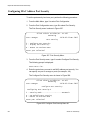
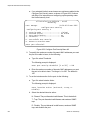
Configuring MAC Address Port Security ........................................................................................................ 562
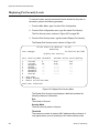
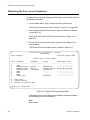
Displaying Port Security Levels ...................................................................................................................... 566
Chapter 31: 802.1x Port-based Network Access Control ........................................................................ 569
Setting Port Roles........................................................................................................................................... 570
Enabling or Disabling 802.1x Port-based Network Access Control................................................................ 572
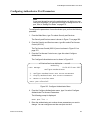
Configuring Authenticator Port Parameters.................................................................................................... 573
Configuring Supplicant Port Parameters ........................................................................................................ 579
Displaying the Port Access Parameters ......................................................................................................... 582
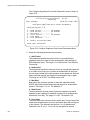
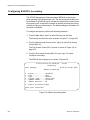
Configuring RADIUS Accounting.................................................................................................................... 584
Section IX: Management Security ......................................................................... 587
Chapter 32: Web Server .............................................................................................................................. 589
Configuring the Web Server ........................................................................................................................... 590
General Steps for Configuring the Web Server for Encryption....................................................................... 593
General Steps for a Self-signed Certificate.............................................................................................. 593
General Steps for a Public or Private CA Certificate................................................................................ 593
Chapter 33: Encryption Keys ..................................................................................................................... 595
Creating an Encryption Key............................................................................................................................ 596
Deleting an Encryption Key ............................................................................................................................ 600
Modifying an Encryption Key .......................................................................................................................... 601
Exporting an Encryption Key .......................................................................................................................... 602
Importing an Encryption Key .......................................................................................................................... 605
Displaying the Encryption Keys ...................................................................................................................... 608
Chapter 34: PKI Certificates and SSL ........................................................................................................ 611
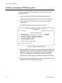
Creating a Self-signed Certificate................................................................................................................... 612
Adding a Certificate to the Database.............................................................................................................. 616
Modifying a Certificate .................................................................................................................................... 619
Deleting a Certificate ...................................................................................................................................... 622
Viewing a Certificate....................................................................................................................................... 624
Generating an Enrollment Request ................................................................................................................ 627
9
Contents
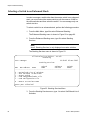
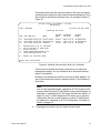
Installing CA Certificates onto a Switch ..........................................................................................................630
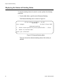
Viewing and Configuring the Maximum Number of Certificates......................................................................631
Configuring SSL ..............................................................................................................................................632
Chapter 35: Secure Shell (SSH) ..................................................................................................................633
Configuring SSH .............................................................................................................................................634
Displaying SSH Information ............................................................................................................................637
Chapter 36: TACACS+ and RADIUS Protocols .........................................................................................639
Enabling or Disabling Server-based Management Authentication..................................................................640
Configuring the TACACS+ Client....................................................................................................................642
Displaying the TACACS+ Settings..................................................................................................................644
Configuring the RADIUS Client .......................................................................................................................645
Displaying RADIUS Status and Settings.........................................................................................................648
Chapter 37: Management Access Control List ..........................................................................................651
Enabling or Disabling the Management ACL ..................................................................................................652
Creating an ACE .............................................................................................................................................654
Modifying an ACE ...........................................................................................................................................656
Deleting an ACE .............................................................................................................................................658
Displaying the ACEs .......................................................................................................................................659
Index ..............................................................................................................................................................661
10
Figures
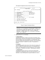
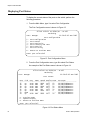
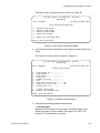
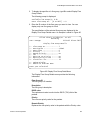
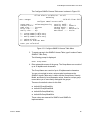
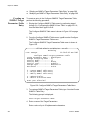
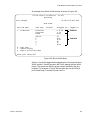
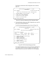
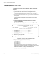
Figure 1: System Administration Menu.................................................................................................................................32
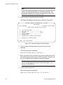
Figure 2: System Configuration Menu ..................................................................................................................................33
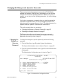
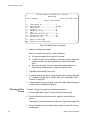
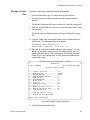
Figure 3: Authentication Configuration Menu .......................................................................................................................35
Figure 4: Passwords Configuration Menu.............................................................................................................................36
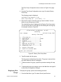
Figure 5: Configure System Time Menu ...............................................................................................................................39
Figure 6: System Utilities Menu ............................................................................................................................................43
Figure 7: Console (Serial/Telnet) Configuration Menu .........................................................................................................45
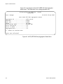
Figure 8: System Information Menu......................................................................................................................................52
Figure 9: System Hardware Information Menu .....................................................................................................................55
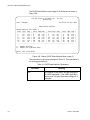
Figure 10: Uplink Information Menu......................................................................................................................................57
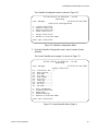
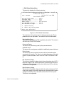
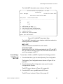
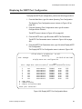
Figure 11: GBIC/SFP Information Menu (Page 1) ................................................................................................................58
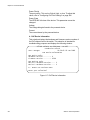
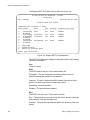
Figure 12: GBIC/SFP Information Menu (Page 2) ................................................................................................................59
Figure 13: Port Configuration Menu......................................................................................................................................62
Figure 14: Port Status Menu.................................................................................................................................................62
Figure 15: Port Configuration (Port) Menu............................................................................................................................65
Figure 16: Head of Line Blocking .........................................................................................................................................69
Figure 17: Flow Control Menu ..............................................................................................................................................72
Figure 18: Filtering Menu......................................................................................................................................................73
Figure 19: Rate Limiting Menu..............................................................................................................................................75
Figure 20: Port Statistics Menu.............................................................................................................................................80
Figure 21: Display Port Statistics Menu................................................................................................................................81
Figure 22: Enhanced Stacking Menu ...................................................................................................................................86
Figure 23: Stacking Services Menu ......................................................................................................................................88
Figure 24: Stacking Services Menu With List of Switches....................................................................................................89
Figure 25: Enhanced Stacking Menu ...................................................................................................................................92
Figure 26: SNMP Configuration Menu..................................................................................................................................94
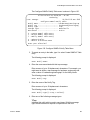
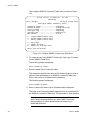
Figure 27: Configure SNMPv1 & SNMPv2c Community Menu ............................................................................................96
Figure 28: Modify SNMP Community Menu .........................................................................................................................99
Figure 29: Display SNMP Community Menu ......................................................................................................................104
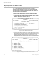
Figure 30: MAC Address Tables Menu...............................................................................................................................106
Figure 31: Display Unicast MAC Addresses Menu.............................................................................................................106
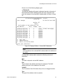
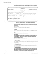
Figure 32: Display All Menu - Unicast MAC Addresses......................................................................................................107
Figure 33: Display All Menu - Multicast MAC Addresses ...................................................................................................108
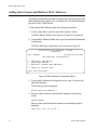
Figure 34: MAC Addresses Configuration Menu ................................................................................................................110
Figure 35: Port Trunking and LACP Menu..........................................................................................................................116
Figure 36: Static Port Trunking Menu .................................................................................................................................117
Figure 37: Create Trunk Menu............................................................................................................................................118
Figure 38: Modify Trunk Menu............................................................................................................................................121
Figure 39: LACP (IEEE 8023ad) Configuration Menu ........................................................................................................126
Figure 40: Create LACP (IEEE 8023ad) Aggregator Menu ................................................................................................130
Figure 41: Modify LACP (IEEE 8023ad) Aggregator Menu ................................................................................................132
Figure 42: LACP (IEEE 802.3ad Port Status Menu ............................................................................................................135
Figure 43: LACP (IEEE 802.3ad) Aggregator Status Menu................................................................................................136
Figure 44: Port Mirroring Menu #1......................................................................................................................................138
Figure 45: Port Mirroring Menu #2......................................................................................................................................138
Figure 46: Port Mirroring Menu...........................................................................................................................................142
Figure 47: File Operations Menu ........................................................................................................................................147
Figure 48: View File Menu with Sample Boot Configuration File........................................................................................152
Figure 49: List Files Menu for Flash Memory and a Compact Flash Card .........................................................................160
Figure 50: List Files Menu for a Compact Flash Card ........................................................................................................161
11
Figures
Figure 51: Display Flash Information Menu ........................................................................................................................162
Figure 52: Display Compact Flash Information Menu.........................................................................................................164
Figure 53: Set/Change Compact Flash Directory Menu .....................................................................................................166
Figure 54: Downloads and Uploads Menu..........................................................................................................................170
Figure 55: HyperTerminal Window .....................................................................................................................................172
Figure 56: Send File Window..............................................................................................................................................172
Figure 57: XModem File Send Window ..............................................................................................................................173
Figure 58: HyperTerminal Window .....................................................................................................................................186
Figure 59: Send File Window..............................................................................................................................................186
Figure 60: XModem File Send Window ..............................................................................................................................187
Figure 61: HyperTerminal Window .....................................................................................................................................193
Figure 62: Receive File Window .........................................................................................................................................194
Figure 63: Event Log Menu ................................................................................................................................................198
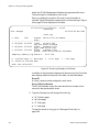
Figure 64: Event Log Example in Normal Mode .................................................................................................................203
Figure 65: Event Log Example in Full Mode .......................................................................................................................204
Figure 66: Sample Log File View ........................................................................................................................................207
Figure 67: Configure Log Outputs Menu.............................................................................................................................210
Figure 68: Syslog Output Configuration Menu....................................................................................................................211
Figure 69: Configure Log Outputs Menu with a Syslog Output Definition...........................................................................215
Figure 70: Syslog Output Configuration Menu for Selected Output ID ...............................................................................217
Figure 71: Security and Services Menu ..............................................................................................................................220
Figure 72: Classifier Configuration Menu............................................................................................................................221
Figure 73: Create Classifier Menu (Page 1) .......................................................................................................................221
Figure 74: Create Classifier Menu (Page 2) .......................................................................................................................222
Figure 75: Show Classifiers Menu ......................................................................................................................................228
Figure 76: Display Classifier Details Menu (Page 1) ..........................................................................................................229
Figure 77: Display Classifier Details Menu (Page 2) ..........................................................................................................230
Figure 78: Access Control Lists (ACL) Menu......................................................................................................................232
Figure 79: Create ACL Menu ..............................................................................................................................................233
Figure 80: Modify ACL Menu ..............................................................................................................................................235
Figure 81: Destroy ACL Menu ............................................................................................................................................237
Figure 82: Show ACLs Menu ..............................................................................................................................................240
Figure 83: Display ACL Details Menu .................................................................................................................................241
Figure 84: Class of Service (CoS) Menu ............................................................................................................................244
Figure 85: Configure Port COS Priorities Menu..................................................................................................................245
Figure 86: Map CoS Priority to Egress Queue Menu..........................................................................................................247
Figure 87: Configure Egress Scheduling Menu ..................................................................................................................248
Figure 88: Show Port CoS Priorities Menu .........................................................................................................................250
Figure 89: Quality of Service (QoS) menu ..........................................................................................................................252
Figure 90: Flow Group Configuration Menu........................................................................................................................253
Figure 91: Create Flow Group Menu ..................................................................................................................................253
Figure 92: Modify Flow Group Menu...................................................................................................................................256
Figure 93: Destroy Flow Group Menu.................................................................................................................................257
Figure 94: Show Flow Groups Menu ..................................................................................................................................258
Figure 95: Display Flow Group Detail Menu .......................................................................................................................259
Figure 96: Traffic Class Configuration Menu ......................................................................................................................261
Figure 97: Create Traffic Class Menu .................................................................................................................................262
Figure 98: Modify Traffic Class Menu .................................................................................................................................266
Figure 99: Destroy Traffic Class Menu ...............................................................................................................................267
Figure 100: Show Traffic Classes Menu .............................................................................................................................268
Figure 101: Display Traffic Class Details Menu ..................................................................................................................269
Figure 102: Policy Configuration Menu...............................................................................................................................271
Figure 103: Create Policy Menu .........................................................................................................................................272
Figure 104: Modify Policy Menu..........................................................................................................................................274
Figure 105: Show Policies Menu ........................................................................................................................................276
Figure 106: Display Policy Details Menu ............................................................................................................................277
Figure 107: Denial of Service (DoS) Menu .........................................................................................................................280
Figure 108: LAN IP Subnet Menu .......................................................................................................................................280
Figure 109: SYN Flood Configuration Menu .......................................................................................................................282
Figure 110: Power Over Ethernet Configuration Menu.......................................................................................................284
12
AT-S63 Management Software Menus User’s Guide
Figure 111: PoE Global Configuration Menu ......................................................................................................................284
Figure 112: PoE Port Configuration Menu..........................................................................................................................286
Figure 113: PoE Status Menu ............................................................................................................................................288
Figure 114: PoE Global Status Menu .................................................................................................................................289
Figure 115: PoE Summary Ports Status Menu...................................................................................................................290
Figure 116: PoE Summary Ports Status Menu...................................................................................................................291
Figure 117: PoE Device Information...................................................................................................................................292
Figure 118: Advanced Configuration Menu ........................................................................................................................296
Figure 119: IGMP Snooping Configuration Menu...............................................................................................................297
Figure 120: View IGMP Multicast Hosts List Menu.............................................................................................................301
Figure 121: View IGMP Multicast Routers List Menu .........................................................................................................303
Figure 122: MLD Snooping Configuration Menu ................................................................................................................306
Figure 123: View MLD Multicast Hosts List Menu ..............................................................................................................310
Figure 124: View MLD Multicast Routers List Menu...........................................................................................................312
Figure 125: RRP Snooping Menu.......................................................................................................................................316
Figure 126: Configure SNMPv3 Table Menu......................................................................................................................322
Figure 127: Configure SNMPv3 User Table Menu .............................................................................................................322
Figure 128: Modify SNMPv3 User Table Menu ..................................................................................................................326
Figure 129: Configure SNMPv3 View Table Menu .............................................................................................................332
Figure 130: Modify SNMPv3 View Table Menu ..................................................................................................................336
Figure 131: Configure SNMPv3 Access Table Menu .........................................................................................................341
Figure 132: Modify SNMPv3 Access Table Menu ..............................................................................................................347
Figure 133: Configure SNMPv3 SecurityToGroup Table Menu..........................................................................................357
Figure 134: Modify SNMPv3 SecurityToGroup Table Menu...............................................................................................361
Figure 135: Configure SNMPv3 Notify Table Menu............................................................................................................365
Figure 136: Modify SNMPv3 Notify Table Menu.................................................................................................................368
Figure 137: Configure SNMPv3 Target Address Table Menu ............................................................................................373
Figure 138: Modify SNMPv3 Target Address Table Menu .................................................................................................377
Figure 139: Configure SNMPv3 Target Parameters Table Menu.......................................................................................386
Figure 140: Modify SNMPv3 Target Parameters Table Menu............................................................................................391
Figure 141: Configure SNMPv3 Community Table Menu...................................................................................................400
Figure 142: Modify SNMPv3 Community Table Menu........................................................................................................404
Figure 143: Display SNMPv3 Table Menu..........................................................................................................................409
Figure 144: Display SNMPv3 User Table Menu .................................................................................................................409
Figure 145: Display SNMPv3 View Table Menu.................................................................................................................410
Figure 146: Display SNMPv3 Access Table Menu .............................................................................................................411
Figure 147: Display SNMPv3 SecurityToGroup Table Menu .............................................................................................412
Figure 148: Display SNMPv3 Notify Table Menu ...............................................................................................................412
Figure 149: Display SNMPv3 Target Address Table Menu ................................................................................................413
Figure 150: Display SNMPv3 Target Parameters Table Menu...........................................................................................414
Figure 151: Display SNMPv3 Community Table Menu ......................................................................................................415
Figure 152: Spanning Tree Configuration Menu.................................................................................................................420
Figure 153: STP Menu .......................................................................................................................................................423
Figure 154: STP Port Parameters Menu ............................................................................................................................426
Figure 155: Configure STP Port Settings Menu .................................................................................................................426
Figure 156: Display STP Port Configuration Menu.............................................................................................................428
Figure 157: RSTP Menu .....................................................................................................................................................431
Figure 158: RSTP Port Parameters Menu..........................................................................................................................433
Figure 159: Configure RSTP Port Settings Menu...............................................................................................................434
Figure 160: Display RSTP Port Configuration Menu ..........................................................................................................436
Figure 161: Display RSTP Port State Menu .......................................................................................................................437
Figure 162: MSTP Configuration Menu ..............................................................................................................................441
Figure 163: CIST Menu ......................................................................................................................................................445
Figure 164: MSTI Menu ......................................................................................................................................................447
Figure 165: VLAN-MSTI Association Menu ........................................................................................................................453
Figure 166: MSTP Port Parameters Menu .........................................................................................................................458
Figure 167: Configure MSTP Port Settings Menu ..............................................................................................................458
Figure 168: Configure Per Spanning Tree Port Settings Menu ..........................................................................................461
Figure 169: Display MSTP Port Configuration Menu..........................................................................................................463
Figure 170: Display MSTP Port State Menu.......................................................................................................................466
Figure 171: VLAN Configuration Menu...............................................................................................................................472
13
Figures
Figure 172: Configure VLANs Menu ...................................................................................................................................473
Figure 173: Create VLAN Menu..........................................................................................................................................473
Figure 174: Modify VLAN Menu..........................................................................................................................................481
Figure 175: Expanded Modify VLAN Menu.........................................................................................................................482
Figure 176: Show VLANs Menu..........................................................................................................................................485
Figure 177: Delete VLAN Menu ..........................................................................................................................................487
Figure 178: Expanded Delete VLAN Menu.........................................................................................................................488
Figure 179: Show PVIDs Menu...........................................................................................................................................492
Figure 180: GARP-GVRP Menu .........................................................................................................................................496
Figure 181: GVRP Port Parameters Menu .........................................................................................................................498
Figure 182: Configure GVRP Port Settings Menu ..............................................................................................................499
Figure 183: Display GVRP Port Configuration Menu..........................................................................................................501
Figure 184: Other GVRP Parameters Menu .......................................................................................................................502
Figure 185: GVRP Counters Menu (page 1).......................................................................................................................503
Figure 186: GVRP Counters Menu (page 2).......................................................................................................................504
Figure 187: GVRP Database Menu ....................................................................................................................................507
Figure 188: GIP Connected Ports Ring Menu ....................................................................................................................509
Figure 189: GVRP State Machine Menu (page 1) ..............................................................................................................511
Figure 190: Display GVRP State Machine Menu (page 2) .................................................................................................512
Figure 191: VLAN Configuration Menu (Multiple VLAN Mode)...........................................................................................518
Figure 192: Show VLANs Menu, Multiple VLANS ..............................................................................................................519
Figure 193: Create VLAN Menu..........................................................................................................................................522
Figure 194: Expanded Modify VLAN Menu.........................................................................................................................526
Figure 195: Show VLANs Menu..........................................................................................................................................528
Figure 196: Show VLANs Menu..........................................................................................................................................529
Figure 197: Delete VLAN Menu ..........................................................................................................................................530
Figure 198: Expanded Delete VLAN Menu.........................................................................................................................531
Figure 199: MAC Based VLANs Menu ...............................................................................................................................536
Figure 200: Delete VLAN Menu ..........................................................................................................................................540
Figure 201: Expanded Delete VLAN Menu.........................................................................................................................541
Figure 202: Show VLANs Menu with MAC Address-based VLANs....................................................................................542
Figure 203: Detail Information Display................................................................................................................................543
Figure 204: Configure Interface Menu ................................................................................................................................548
Figure 205: Create Interface Menu .....................................................................................................................................549
Figure 206: Modify Interface Menu .....................................................................................................................................552
Figure 207: Port Security Menu ..........................................................................................................................................562
Figure 208: Configure Port Security Menu #1.....................................................................................................................562
Figure 209: Configure Port Security Menu #2.....................................................................................................................564
Figure 210: Display Port Security Menu .............................................................................................................................566
Figure 211: Port Access Control (802.1X) Menu ................................................................................................................570
Figure 212: Configure Port Access Role Menu...................................................................................................................571
Figure 213: Configure Authenticator Menu .........................................................................................................................573
Figure 214: Configure Authenticator Port Access Parameters Menu .................................................................................574
Figure 215: Configure Supplicant Menu .............................................................................................................................579
Figure 216: Configure Supplicant Port Access Parameters Menu......................................................................................580
Figure 217: Display Port Access Status Menu....................................................................................................................582
Figure 218: Radius Accounting Menu.................................................................................................................................584
Figure 219: Web Server Configuration Menu .....................................................................................................................590
Figure 220: Web Server Configuration Menu Configured for HTTPS.................................................................................591
Figure 221: Keys/Certificate Configuration Menu ...............................................................................................................596
Figure 222: Key Management Menu...................................................................................................................................597
Figure 223: Create Key Menu.............................................................................................................................................597
Figure 224: Export Key to File Menu ..................................................................................................................................603
Figure 225: Import Key from File Menu ..............................................................................................................................606
Figure 226: Key Management Menu...................................................................................................................................608
Figure 227: Public Key Infrastructure (PKI) Configuration Menu ........................................................................................613
Figure 228: X509 Certificate Management Menu ...............................................................................................................613
Figure 229: Create Self-Signed Certificate Menu ...............................................................................................................614
Figure 230: Add Certificate Menu .......................................................................................................................................616
Figure 231: Modify Certificate Menu ...................................................................................................................................620
14
AT-S63 Management Software Menus User’s Guide
Figure 232: View Certificate Details Menu (page 1) ...........................................................................................................625
Figure 233: View Certificate Details Menu (page 2) ...........................................................................................................626
Figure 234: Generate Enrollment Request Menu ...............................................................................................................628
Figure 235: Secure Socket Layer (SSL) Menu ...................................................................................................................632
Figure 236: Secure Shell (SSH) Menu ...............................................................................................................................634
Figure 237: Show Server Information Menu .......................................................................................................................637
Figure 238: Authentication Configuration Menu .................................................................................................................640
Figure 239: TACACS+ Client Configuration Menu .............................................................................................................642
Figure 240: TACACS+ Client Configuration Menu .............................................................................................................644
Figure 241: RADIUS Client Configuration ..........................................................................................................................645
Figure 242: RADIUS Server Configuration .........................................................................................................................646
Figure 243: Show Status Menu ..........................................................................................................................................648
Figure 244: Management ACL Configuration Menu ...........................................................................................................652
Figure 245: Modify Management ACL Entry.......................................................................................................................656
Figure 246: Display All Management ACL Entries Menu....................................................................................................659
15
Figures
16
Tables
Table 1: AT-S63 Modules ..................................................................................................................................................201
Table 2: Event Severity Levels ..........................................................................................................................................203
Table 3: Applicable RFC 3164 Numerical Code and AT-S63 Module Mappings ..............................................................212
Table 4: Numerical Code and Facility Level Mappings ......................................................................................................213
Table 5: Bridge Priority Value Increments .........................................................................................................................424
Table 6: Port Priority Value Increments .............................................................................................................................427
Table 7: STP Auto-Detect Port Costs ................................................................................................................................427
Table 8: STP Auto-Detect Port Trunk Costs ......................................................................................................................427
Table 9: RSTP Auto-Detect Port Costs .............................................................................................................................434
Table 10: RSTP Auto-Detect Port Trunk Costs .................................................................................................................435
Table 11: Auto External Path Costs ..................................................................................................................................459
Table 12: Auto External Path Trunk Costs ........................................................................................................................459
Table 13: RSTP Auto-Detect Port Costs ...........................................................................................................................461
Table 14: RSTP Auto-Detect Port Trunk Costs .................................................................................................................462
Table 15: GVRP Counters .................................................................................................................................................504
Table 16: GVRP State Machine Parameters .....................................................................................................................512
17
Tables
18
Preface
This guide contains instructions on how to configure the AT-9400 Layer 2+
and Basic Layer 3 Gigabit Ethernet Switches from the menus of the
AT-S63 Management Software.
This preface contains the following sections:
“How This Guide is Organized” on page 20
“Product Documentation” on page 22
“Where to Go First” on page 23
“Starting a Management Session” on page 24
“Document Conventions” on page 25
“Where to Find Web-based Guides” on page 26
“Contacting Allied Telesis” on page 27
Caution
The software described in this documentation contains certain
cryptographic functionality and its export is restricted by U.S. law. As
of this writing, it has been submitted for review as a “retail encryption
item” in accordance with the Export Administration Regulations, 15
C.F.R. Part 730-772, promulgated by the U.S. Department of
Commerce, and conditionally may be exported in accordance with
the pertinent terms of License Exception ENC (described in 15
C.F.R. Part 740.17). In no case may it be exported to Cuba, Iran,
Iraq, Libya, North Korea, Sudan, or Syria. If you wish to transfer this
software outside the United States or Canada, please contact your
local Allied Telesis sales representative for current information on
this product’s export status.
19
Preface
How This Guide is Organized
This guide contains the following sections and chapters:
Section I: Basic Operations
Chapter 1, “Basic Switch Parameters” on page 31
Chapter 2, “Port Parameters” on page 61
Chapter 3, “Enhanced Stacking” on page 85
Chapter 4, “SNMPv1 and SNMPv2c” on page 93
Chapter 5, “MAC Address Table” on page 105
Chapter 6, “Static Port Trunks” on page 115
Chapter 7, “LACP Port Trunks” on page 125
Chapter 8, “Port Mirroring” on page 137
Section II: Advanced Operations
Chapter 9, “File System” on page 145
Chapter 10, “File Downloads and Uploads” on page 167
Chapter 11, “Event Logs and the Syslog Client” on page 197
Chapter 12, “Classifiers” on page 219
Chapter 13, “Access Control Lists” on page 231
Chapter 14, “Class of Service” on page 243
Chapter 15, “Quality of Service” on page 251
Chapter 16, “Denial of Service Defenses” on page 279
Chapter 17, “Power Over Ethernet” on page 283
Section III: Snooping Protocols
Chapter 18, “IGMP Snooping” on page 295
Chapter 19, “MLD Snooping” on page 305
Chapter 20, “RRP Snooping” on page 315
Section IV: SNMPv3
Chapter 21, “SNMPv3” on page 319
20
AT-S63 Management Software Menus User’s Guide
Section V: Spanning Tree Protocols
Chapter 22, “Spanning Tree and Rapid Spanning Tree Protocols” on
page 419
Chapter 23, “Multiple Spanning Tree Protocol” on page 439
Section VI: Virtual LANs
Chapter 24, “Port-based and Tagged VLANs” on page 471
Chapter 25, “GARP VLAN Registration Protocol” on page 495
Chapter 26, “Multiple VLAN Modes” on page 515
Chapter 27, “Protected Ports VLANs” on page 521
Chapter 28, “MAC Address-based VLANs” on page 533
Section VII: Internet Protocol Routing
Chapter 29, “Internet Protocol Version 4 Routing Interfaces” on page
547
Section VIII: Port Security
Chapter 30, “MAC Address-based Port Security” on page 561
Chapter 31, “802.1x Port-based Network Access Control” on page 569
Section IX: Management Security
Chapter 32, “Web Server” on page 589
Chapter 33, “Encryption Keys” on page 595
Chapter 34, “PKI Certificates and SSL” on page 611
Chapter 35, “Secure Shell (SSH)” on page 633
Chapter 36, “TACACS+ and RADIUS Protocols” on page 639
Chapter 37, “Management Access Control List” on page 651
21
Preface
Product Documentation
For overview information on the features of the AT-9400 Switch and the
AT-S63 Management Software, refer to:
AT-S63 Management Software Features Guide
(PN 613-001022)
For instructions on starting a local or remote management session on a
stand-alone AT-9400 Switch or a stack, refer to:
Starting an AT-S63 Management Session Guide
(PN 613-001023)
For instructions on installing or managing a stand-alone AT-9400 Switch,
refer to:
AT-9400 Gigabit Ethernet Switch Installation Guide
(PN 613-000987)
AT-S63 Management Software Menus User’s Guide
(PN 613-001025)
AT-S63 Management Software Command Line User’s Guide
(PN 613-001024)
AT-S63 Management Software Web Browser User’s Guide
(PN 613-001026)
For instructions on installing or managing a stack of AT-9400 Basic Layer
3 Switches, refer to:
22
AT-9400 Stack Installation Guide
(PN 613-000796)
AT-S63 Stack Command Line User’s Guide
(PN 613-001027)
AT-S63 Stack Web Browser User’s Guide
(PN 613-001028)
AT-S63 Management Software Menus User’s Guide
Where to Go First
Allied Telesis recommends that you read Chapter 1, Overview, in the
AT-S63 Management Software Features Guide before you begin to
manage the switch for the first time. There you will find a variety of basic
information about the unit and the management software, like the two
levels of manager access levels and the different types of management
sessions.
The AT-S63 Management Software Features Guide is also your resource
for background information on the features of the switch. You can refer
there for the relevant concepts and guidelines when you configure a
feature for the first time.
23
Preface
Starting a Management Session
For instructions on how to start a local or remote management session on
the AT-9400 Switch, refer to the Starting an AT-S63 Management Session
Guide.
24
AT-S63 Management Software Menus User’s Guide
Document Conventions
This document uses the following conventions:
Note
Notes provide additional information.
Caution
Cautions inform you that performing or omitting a specific action may
result in equipment damage or loss of data.
Warning
Warnings inform you that performing or omitting a specific action
may result in bodily injury.
25
Preface
Where to Find Web-based Guides
The installation and user guides for all Allied Telesis products are
available in portable document format (PDF) on our web site at
www.alliedtelesis.com. You can view the documents online or download
them onto a local workstation or server.
26
AT-S63 Management Software Menus User’s Guide
Contacting Allied Telesis
This section provides Allied Telesis contact information for technical
support and for sales and corporate information.
Online Support
You can request technical support online from the Allied Telesis
Knowledge Base at www.alliedtelesis.com/support/kb.aspx. You can
submit questions to our technical support staff from the Knowledge Base
and review answers to previously asked questions.
Email and
Telephone
Support
For Technical Support by email or telephone, refer to the Allied Telesis
web site at www.alliedtelesis.com. Select your country from the list on
the web site and then select the appropriate tab.
Returning
Products
Products for return or repair must be assigned Return Materials
Authorization (RMA) numbers. A product sent to Allied Telesis without an
RMA number will be returned to the sender at the sender’s expense.
To obtain an RMA number, contact the Allied Telesis Technical Support
group at www.alliedtelesis.com/support/rma.aspx.
Sales and
Corporate
Information
Management
Software Updates
You can contact Allied Telesis for sales or corporate information at our
web site at www.alliedtelesis.com.
New releases of the management software for our managed products are
available from the following Internet sites:
Allied Telesis web site: www.alliedtelesis.com
Allied Telesis FTP server: ftp://ftp.alliedtelesis.com
If the FTP server prompts you to log on, enter “anonymous” as the user
name and your email address as the password.
27
Preface
28
Section I
Basic Operations
The chapters in this section provide information and procedures for basic
switch setup using the AT-S63 Management Software. The chapters
include:
Section I: Basic Operations
Chapter 1, ”Basic Switch Parameters” on page 31
Chapter 2, ”Port Parameters” on page 61
Chapter 3, ”Enhanced Stacking” on page 85
Chapter 4, ”SNMPv1 and SNMPv2c” on page 93
Chapter 5, ”MAC Address Table” on page 105
Chapter 6, ”Static Port Trunks” on page 115
Chapter 7, “LACP Port Trunks” on page 125
Chapter 8, ”Port Mirroring” on page 137
29
30
Section I: Basic Operations
Chapter 1
Basic Switch Parameters
This chapter contains the following procedures:
Section I: Basic Operations
“Configuring the Switch’s Name, Location, and Contact” on page 32
“Changing the Manager and Operator Passwords” on page 35
“Setting the System Time” on page 38
“Rebooting the Switch” on page 43
“Configuring the Console Startup Mode” on page 45
“Configuring the Console Timer” on page 46
“Configuring the Telnet Server” on page 47
“Setting the Baud Rate of the Serial Terminal Port” on page 48
“Pinging a Remote System” on page 49
“Returning the AT-S63 Management Software to the Factory Default
Values” on page 50
“Displaying Hardware and Software Information” on page 52
“Displaying System Hardware Information” on page 55
“Displaying Uplink Port Information” on page 57
31
Chapter 1: Basic Switch Parameters
Configuring the Switch’s Name, Location, and Contact
This procedure explains how to assign a name to the switch. The name
appears at the top of the menus. Names can help you identify your
switches when you manage them and help you avoid performing a
configuration procedure on the wrong switch. This procedure also assigns
the name of the administrator responsible for maintaining the unit and the
location of the switch.
To assign a name, location, and contact to a switch, perform the following
procedure:
1. From the Main Menu, type 5 to select System Administration.
The System Administration menu is shown in Figure 1.
Allied Telesis AT-9424Ts - AT-S63
Marketing
User: Manager
11:20:02 02-Mar-2005
System Administration
1
2
3
4
5
6
7
8
9
-
System Information
System Configuration
Console (Serial/Telnet) Configuration
Web Server Configuration
SNMP Configuration
Authentication Configuration
Management ACL
Event Log
System Utilities
R - Return to Previous Menu
Enter your selection?
Figure 1. System Administration Menu
2. From the System Administration menu, type 2 to select System
Configuration.
32
Section I: Basic Operations
AT-S63 Management Software Menus User’s Guide
The System Configuration menu is shown in Figure 2.
Allied Telesis AT-9424Ts - AT-S63
Marketing
User: Manager
11:20:02 02-Mar-2006
System Configuration
1
2
3
4
5
6
7
8
-
Eth0 Interface.............
IP Address ................
Subnet Mask ...............
Default Gateway ...........
System Name ...............
Location ..................
Administrator .............
ARP Cache Timeout .........
vlan2-0
184.35.62.11
255.255.255.0
184.35.62.4
150 seconds
T - Configure System Time
I - Configure Interface
R - Return to Previous Menu
Enter your selection?
Figure 2. System Configuration Menu
Note
Selections 1 to 4 are described in “Displaying the IP Address of the
Local Interface” on page 555. Selection 8, ARP Cache Timeout, is
described in “Setting the ARP Cache Timeout” on page 558.
Selection T, Configure System Time, is described in “Setting the
System Time” on page 38.
3. Adjust options 5 to 7 as necessary.
5 - System Name
This parameter specifies a name for the switch (for example, Sales
Ethernet switch). The name is displayed at the top of the management
menus and pages. The name can be from 1 to 39 characters. The
name can include spaces and special characters, such as exclamation
points and asterisks. The default is no name. This parameter is
optional.
6 - Location
This parameter specifies the location of the switch, (for example, 4th
Floor - rm 402B). The location can be from 1 to 20 characters. The
location can include spaces and special characters, such as dashes
and asterisks. The default is no location. This parameter is optional.
7 - Administrator
This parameter specifies the name of the network administrator
responsible for managing the switch. The name can be from 1 to 20
characters. It can include spaces and special characters, such as
Section I: Basic Operations
33
Chapter 1: Basic Switch Parameters
dashes and asterisks. The default is no name. This parameter is
optional.
4. After making changes, type R until you return to the Main Menu. Then
type S to select Save Configuration Changes.
34
Section I: Basic Operations
AT-S63 Management Software Menus User’s Guide
Changing the Manager and Operator Passwords
There are two levels of management access on the AT-9400 Switch:
manager and operator. When you log in as manager, you can view and
configure all of a switch’s operating parameters. When you log in as an
operator, you can only view the operating parameters; you cannot change
any values.
You log in as a manager or an operator when you enter the appropriate
username and password when you start a management session. The
default password for manager access is “friend.” The default password for
operator access is “operator.” Passwords are case sensitive.
This section contains these two procedures:
“Changing the Manager or Operator Password” on page 35
“Resetting the Manager Password” on page 37
The first procedure allows you to change the manager or operator
password. The second procedure allows you to bypass the manager
password in the event you lose or forget it.
Changing the
Manager or
Operator
Password
To change the manager or operator password, perform the following
procedure:
1. From the Main Menu, type 5 to select System Administration.
The System Administration menu is shown in Figure 1 on page 32.
2. From the System Administration menu, type 6 to select Authentication
Configuration.
The Authentication Configuration menu is shown in Figure 3.
Allied Telesis AT-9424Ts - AT-S63
Marketing
User: Manager
11:20:02 02-Mar-2005
Authentication Configuration
1
2
3
4
5
-
Server-based Authentication ..... Disabled
Authentication Method ........... TACACS+
TACACS+ Configuration
RADIUS Configuration
Passwords Configuration
R - Return to Previous Menu
Enter your selection?
Figure 3. Authentication Configuration Menu
Section I: Basic Operations
35
Chapter 1: Basic Switch Parameters
3. From the Authentication Configuration menu, type 5 to select
Passwords Configuration.
The Passwords Configuration menu is shown in Figure 4.
Allied Telesis AT-9424Ts - AT-S63
Marketing
User: Manager
11:20:02 02-Mar-2005
Passwords Configuration
1 - Set Manager Password
2 - Set Operator Password
R - Return to Previous Menu
Enter your selection?
Figure 4. Passwords Configuration Menu
4. From the Passwords Configuration menu, type 1 to select Set
Manager Password.
The following prompt is displayed:
Enter Current Manager Password ->
5. Type the current manager password (the default is “friend”) and press
Return.
The following prompt is displayed:
Enter New Manager Password ->
6. When prompted, re-enter the new password.
7. Type 2 to select Set Operator Password.
The following prompt is displayed:
Enter New Operator Password ->
8. Type the current operator password (the default is “friend”) and press
Return.
Note
A password can be from 0 to 16 alphanumeric characters.
Passwords are case sensitive. You should not use spaces or special
characters, such as asterisks (*) or exclamation points (!), in a
password if you are managing the switch from a web browser. Many
web browsers cannot handle special characters in passwords.
36
Section I: Basic Operations
AT-S63 Management Software Menus User’s Guide
9. After making changes, type R until you return to the Main Menu. Then
type S to select Save Configuration Changes.
Resetting the
Manager
Password
This procedure can be used to bypass the login on the switch in the event
you forget the manager password. This procedure must be performed
from a local management session.
Caution
With this procedure, any person with physical access to the switch
can gain access to the unit’s management software without a user
name or password. For this reason, all AT-9400 Switches should be
maintained in a locked wiring closet or other secure location to
prevent unauthorized management access.
Note
This procedure requires rebooting the switch. Some network traffic
may be lost.
To reset the manager password, perform the following procedure:
1. Establish a local management session with the switch.
2. Reboot the switch. Refer to “Rebooting the Switch” on page 43 for
instructions.
3. When the switch displays “Press <Ctrl> B to go to Boot prompt,” type S
or s.
The switch, without acknowledging the key input, continues with the
process of initializing the management software.
4. At the completion of the initialization process, press Return.
You are automatically logged on with manager privileges. The
command line interface is displayed.
5. Change the manager’s password from either the command line
interface or the menus interface. For instructions on how to change the
password from the menus interface, refer to “Changing the Manager or
Operator Password” on page 35.
This completes the procedure for resetting the manager password.
You can continue to manage the switch or quit from the management
session. You must use the new password the next time you log on to
the switch at the start of a management session.
Section I: Basic Operations
37
Chapter 1: Basic Switch Parameters
Setting the System Time
This procedure explains how to set the switch’s date and time. Setting the
system time is important if you configured the switch to send traps to your
management stations. Traps from a switch where the time has not been
set do not contain the correct date and time. Therefore, it becomes difficult
for you to determine when the events represented by the traps occurred.
It is also important to set the system time if you intend to use the Secure
Sockets Layer (SSL) certificate feature described in, Chapter 34, ”PKI
Certificates and SSL” on page 611. Certificates must contain the date and
time when they are created.
There are two ways to set the switch’s time. One method is to set it
manually. The AT-9400 Switch has an onboard battery that maintains the
date and time even when the unit is powered off or reset. For instructions,
refer to “Setting the System Time Manually,” next.
The second method uses the Simple Network Time Protocol (SNTP). The
AT-S63 Management Software is shipped with the client version of this
protocol. You can configure the AT-S63 Management Software to obtain
the current date and time from an SNTP or Network Time Protocol (NTP)
server located on your network or the Internet. For instructions, refer to
“Setting the System Time from an SNTP or NTP Server” on page 40.
SNTP is a reduced version of the NTP. However, the SNTP client software
in the AT-S63 Management Software is interoperable with NTP servers.
The local subnet on the switch where the SNTP server is a member must
have a routing interface. The switch uses the IP address of the routing
interface as its source address when communicating with the server. To
configure routing interfaces using the menus interface, refer to Chapter
29, “Internet Protocol Version 4 Routing Interfaces” on page 547 in this
guide.
Note
Prior to version 2.0.0 of the AT-S63 Management Software, the
SNTP server had to be a member of the switch’s management
VLAN. This restriction no longer applies. The SNTP server can be
located on any local subnet of the switch, provided the subnet has a
routing interface.
Note
The default system time on the switch is midnight, January 1, 1970.
38
Section I: Basic Operations
AT-S63 Management Software Menus User’s Guide
Setting the
System Time
Manually
To set the system time manually, perform the following procedure:
1. From the Main Menu, type 5 to select System Administration.
The System Administration menu is shown in Figure 1 on page 32.
2. From the System Administration menu, type 2 to select System
Configuration.
The System Configuration menu is shown in Figure 2 on page 33.
3. From the System Configuration menu, type T to select Configure
System Time.
The Configure System Time menu is shown in Figure 5.
Allied Telesis AT-9424Ts - AT-S63
Marketing
User: Manager
11:20:02 02-Mar-2005
Configure System Time
1
2
3
4
5
6
7
-
System Time ...................
SNTP Status ...................
SNTP Server ...................
UTC Offset ....................
Daylight Savings Time (DST) ...
Poll Interval .................
Last Delta ....................
00:00:00 on 01-Jan-1970
Disabled
0.0.0.0
+0
Enabled
600 seconds
+0 seconds
U - Update System Time
R - Return to Previous Menu
Enter your selection?
Figure 5. Configure System Time Menu
4. From the Configure System Time menu, type 1 to select System Time.
The following prompt is displayed:
Enter new system time [hh:mm:ss] ->
5. Enter a new time for the system in the following format: hours, minutes,
and seconds all separated by colons. The following prompt is
displayed:
Enter new system date [dd-mm-yyyy] ->
6. Enter a new date for the system. Use two numbers to specify the day
and month. Use four numbers to specify the year. Separate the values
with hyphens. For example, December 5, 2004 is specified 05-122004.
The new time and date are immediately activated on the switch.
Section I: Basic Operations
39
Chapter 1: Basic Switch Parameters
Setting the
System Time
from an SNTP or
NTP Server
To configure the switch to obtain its date and time from an SNTP or NTP
server on your network or the Internet, perform the following procedure:
1. From the Main Menu, type 5 to select System Administration.
The System Administration menu is shown in Figure 1 on page 32.
2. From the System Administration menu, type 2 to select System
Configuration.
The System Configuration menu is shown in Figure 2 on page 33.
3. From the System Configuration menu, type 8 to select Configure
System Time.
The Configure System Time menu is shown in Figure 5 on page 39.
4. Type 3 to select SNTP Server and enter the IP address of an SNTP or
NTP server.
Note
If the local interface on the switch is obtaining its IP address and
subnet mask from a DHCP server, you can configure the server to
provide the interface with an IP address of an NTP or SNTP server.
If you configured the server to provide this address, then you do not
need to enter it here, and you can skip ahead to step 5.
The following prompt is displayed:
Enter SNTP server IP address ->
5. Enter an IP address of an SNTP or NTP server.
6. Type 4 to select UTC Offset to specify the difference between the UTC
and local time.
Note
If the switch is using DHCP, it automatically attempts to determine
this value. In this case, you do not need to configure a value for the
UTC Offset parameter.
The following prompt is displayed:
Enter UTC Offset [-12 to 12] -> 0
7. Enter a UTC Offset time.
The default is 0 hours. The range is -12 to +12 hours.
40
Section I: Basic Operations
AT-S63 Management Software Menus User’s Guide
8. Type 5 to select Daylight Savings Time (DST) to enable or disable the
switch’s ability to adjust its system time to daylight savings time. The
following prompt is displayed:
Adjust for Daylight Savings Time (E - Enabled, D - Disabled) ->
9. Type E to enable daylight savings time and allow the switch to adjust
system time to daylight savings time. This is the default value. Type D
to disable daylight savings time and not allow the switch to adjust
system time to daylight savings time.
Note
The switch does not set DST automatically. If the switch is in a
locale that uses DST, you must remember to enable this in April
when DST begins and disable it in October when DST ends. If the
switch is in a locale that does not use DST, this option should be set
to disabled all the time.
10. Type 6 to select Poll Interval to specify the time interval between
queries to the SNTP server.
The following prompt is displayed:
Enter interval to poll SNTP server [60 to 1200] -> 600
Note
Selection 7, Last Delta, reports the last adjustment that had to be
applied to the system time; the drift in the system clock between two
successive queries to the SNTP server. You cannot change this
value.
11. Enter the number of seconds the switch waits between polling the
SNTP or NTP server. The default is 600 seconds. The range is from 60
to 1200 seconds.
12. Type 2 to select SNTP Status to enable or disable the SNTP client.
The following prompt is displayed:
SNTP Status (E-Enabled, D-Disabled) ->
13. Type E to enable SNTP client software on the switch or D to disable
the NTP client software and press Return. The default is disabled.
After SNTP is enabled, the switch immediately polls the SNTP or NTP
server for the current date and time. (The switch also automatically
polls the server whenever a change is made to any of the parameters
in this menu, so long as SNTP is enabled.)
Section I: Basic Operations
41
Chapter 1: Basic Switch Parameters
The Last Delta option in the menu displays the last adjustment that
was applied to system time due to a drift in the system clock between
two successive queries to the SNTP server. This is a read only field.
Option U, Update System Time, allows you to prompt the switch to poll
the SNTP or NTP server for the current time and date. You can use
this selection to update the time and date immediately rather than wait
for the switch’s next polling period. This selection has no effect if you
set the date and time manually.
14. After making changes, type R until you return to the Main Menu. Then
type S to select Save Configuration Changes.
42
Section I: Basic Operations
AT-S63 Management Software Menus User’s Guide
Rebooting the Switch
This procedure reboots the switch.
Note
Any configuration changes not saved are lost after the switch
reboots. To save your configuration changes, return to the Main
Menu and type S to select Save Configuration Changes.
Caution
The switch does not forward traffic while it initializes its operating
software. The process can take from 20 seconds to several minutes
to complete, depending on the number and complexity of the
commands in its boot configuration file. Some packet traffic may be
lost. You must reestablish your management session after the
switch finishes reloading its software to continue managing the unit.
To reboot the switch, perform the following procedure:
1. From the Main Menu, type 5 to select System Administration.
The System Administration menu is shown in Figure 1 on page 32.
2. From the System Administration menu, type 9 to select System
Utilities.
The System Utilities menu is shown in Figure 6.
Allied Telesis AT-9424Ts - AT-S63
Marketing
User: Manager
11:20:02 02-Mar-2005
System Utilities
1
2
3
4
5
-
File Operations
Downloads and Uploads
Ping a Remote System
Reset to Factory Defaults
Reboot the Switch
R - Return to Previous Menu
Enter your selection?
Figure 6. System Utilities Menu
Section I: Basic Operations
43
Chapter 1: Basic Switch Parameters
Note
Item 1 - File Operations, is described in Chapter 9, ”File System” on
page 145. Item 2 - Downloads and Uploads is described in Chapter
10, ”File Downloads and Uploads” on page 167. Ping a Remote
System, item 3, is described in “Pinging a Remote System” on
page 49. Reset to Factory Defaults, item 4, is described in
“Returning the AT-S63 Management Software to the Factory Default
Values” on page 50.
3. From the System Utilities menu, type 5 to select Reboot the switch.
The following prompt is displayed:
The switch is about to reboot. Do you want to proceed?
[Yes/No] ->
4. Type Y to reboot the switch or N to cancel the procedure.
44
Section I: Basic Operations
AT-S63 Management Software Menus User’s Guide
Configuring the Console Startup Mode
With this procedure you can control which management interface, menus
or command line, is displayed at the start of your local and remote
management sessions. The default is the command line interface.
To change the console startup mode, perform the following procedure:
1. From the Main Menu, type 5 to select System Administration.
The System Administration menu is shown in Figure 1 on page 32.
2. From the System Administration menu, type 3 to select Console
(Serial/Telnet) Configuration.
The Console (Serial/Telnet) Configuration menu is shown in Figure 7.
Allied Telesis AT-9424Ts - AT-S63
Marketing
User: Manager
11:20:02 02-Mar-2005
Console (Serial/Telnet) Configuration
1
2
3
4
5
-
Console Startup Mode ............
Console Disconnect Interval .....
Console Baud Rate ...............
Telnet Server ...................
Telnet insert NULL ..............
CLI
10 minute(s)
9600
Enabled
OFF
R - Return to Previous Menu
Enter your selection?
Figure 7. Console (Serial/Telnet) Configuration Menu
3. Type 1 to toggle Console Startup Mode between Menu and CLI. When
the mode is set to Menu, management sessions start with the Main
Menu. When the mode is set to CLI, management sessions start with
the command line interface prompt. The default is CLI.
4. After making changes, type R until you return to the Main Menu. Then
type S to select Save Configuration Changes.
A change to the console startup mode takes effect the next time you
start a local management session.
Section I: Basic Operations
45
Chapter 1: Basic Switch Parameters
Configuring the Console Timer
The AT-S63 Management Software uses the console timer, also referred
to as the console disconnect interval, to automatically end inactive local
and remote management sessions. The management software
automatically ends a local or remote management session if a
management session is inactive for the length of time specified by the
console timer. For example, if you specify two minutes as the console
timer, the AT-S63 Management Software automatically ends a
management session if it does not detect any activity from the local or
remote management station after two minutes.
This security feature prevents unauthorized individuals from using your
management station when you step away from your system while you are
configuring a switch. The default for the console timeout value is 10
minutes.
To adjust the console timer, perform the following procedure:
1. From the Main Menu, type 5 to select System Administration.
The System Administration menu is shown in Figure 1 on page 32.
2. From the System Administration menu, type 3 to select Console
(Serial/Telnet) Configuration.
The Console (Serial/Telnet) Configuration menu is shown in Figure 7
on page 45.
3. From the Console (Serial/Telnet) Configuration menu, type 2 to select
Console Disconnect Interval
The following prompt is displayed:
Enter your new value -> [1 to 60]->
4. Enter a new console timer value. The range is 1 to 60 minutes. The
default is 10 minutes.
A change to the console timer is immediately activated on the switch.
5. After making changes, type R until you return to the Main Menu. Then
type S to select Save Configuration Changes.
46
Section I: Basic Operations
AT-S63 Management Software Menus User’s Guide
Configuring the Telnet Server
This procedure describes how to enable and disable the Telnet server on
the switch. You might disable the server to prevent individuals from
managing the switch with a Telnet application or if you intend to use the
Secure Shell (SSH) protocol.
This procedure also explains how to toggle the Telnet server on the switch
so that is adds a NULL character after each CR. Some Telnet clients
require the character in order to correctly display the information from the
Telnet server.
To enable or disable the Telnet server or to set the Telnet NULL character
parameter, perform the following procedure:
1. From the Main Menu, type 5 to select System Administration.
The System Administration menu is shown in Figure 1 on page 32.
2. From the System Administration menu, type 3 to select Console
(Serial/Telnet) Configuration.
The Console (Serial/Telnet) Configuration menu is shown in Figure 7
on page 45.
3. To enable or disable the Telnet server, from the Console (Serial/
Telnet) Configuration menu type 4 to toggle Telnet Server between
Enabled and Disabled. The default is enabled.
Note
Disable Telnet access if you are using the SSH (Secure Shell)
feature. (The SSH feature is not available in all versions of the
AT-S63 Management Software.)
4. To configure the Telnet NULL character parameter, type 5 to toggle
Telnet insert NULL between On and Off. When Off, the default setting,
the Telnet server does not send a NULL character after each CR.
When On, the server does send the character.
A change to the status of the Telnet server or the Telnet NULL
character parameter is immediately implemented on the switch.
5. After making changes, type R until you return to the Main Menu. Then
type S to select Save Configuration Changes.
Section I: Basic Operations
47
Chapter 1: Basic Switch Parameters
Setting the Baud Rate of the Serial Terminal Port
The default baud rate of the RJ-45 type serial terminal port on the switch is
9600 bps.
To change the baud rate, perform the following procedure:
1. From the Main Menu, type 5 to select System Administration.
The System Administration menu is shown in Figure 1 on page 32.
2. From the System Administration menu, type 3 to select Console
(Serial/Telnet) Configuration.
The Console (Serial/Telnet) Configuration menu is shown in Figure 7
on page 45.
3. From the Console (Serial/Telnet) Configuration menu, type 3 to select
Console Baud Rate.
The following prompt is displayed:
Supported baud rates are:
1200, 2400, 4800, 9600, 19200, 38400, 57600, or 115200
Enter new baud rate value --> [1200 to 115200]
4. Type the desired baud rate value and press Return. The default setting
is 9600 bps.
The following message is displayed:
Baud rate changed to [baud rate you typed] bps.
Please change your terminal baud rate correspondingly.
Press <Enter> to continue.
Note
If you are running a local management session, be sure to change
your terminal’s baud rate.
5. Press Return.
48
Section I: Basic Operations
AT-S63 Management Software Menus User’s Guide
Pinging a Remote System
This procedure instructs the switch to ping a remote device on your
network. This can be useful in determining whether a valid link exists
between the switch and another network device.
The local subnet on the switch where the device is a member must have a
routing interface. The switch uses the IP address of the routing interface
as its source address when sending the ping.
Note
Prior to version 2.0.0 of the AT-S63 Management Software, the
switch could ping a device only if the device was a member of the
switch’s management VLAN. This restriction no longer applies. The
switch can ping a device from any local subnet, provided the subnet
has a routing interface.
To instruct the switch to ping a network device, perform the following
procedure:
1. From the Main Menu, type 5 to select System Administration.
The System Administration menu is shown in Figure 1 on page 32.
2. From the System Administration menu, type 9 to select System
Utilities.
The System Utilities menu is shown in Figure 6 on page 43.
3. For the System Utilities menu, type 3 to select Ping a Remote System.
The following prompt is displayed:
Please enter an IP address ->
4. Enter the IP address of the end node you want the switch to ping.
The results of the ping command are displayed on the screen.
5. To stop the ping, press any key.
Section I: Basic Operations
49
Chapter 1: Basic Switch Parameters
Returning the AT-S63 Management Software to the Factory Default
Values
The procedure in this section returns all AT-S63 Management Software
parameters to the default values. Please note the following before you
perform this procedure:
Returning all parameter settings to their default values also deletes all
routing interfaces as well as all port-based and tagged VLANs on the
switch.
This procedure does not delete files from the AT-S63 file system. To
delete files, refer to Chapter 9, ”File System” on page 145.
This procedure does not delete any encryption keys stored in the key
database. To delete encryption keys, refer to “Deleting an Encryption
Key” on page 600.
Returning a switch to its default values does not alter the contents of
the active boot configuration file. To reset the file back to the default
settings, you must reestablish your management session after the
switch reboots and then select Save Configuration changes.
Otherwise the switch reverts back to the previous configuration the
next time you reset the switch.
Note
The AT-S63 Management Software default values are listed in the
AT-S63 Management Software Features Guide.
To return the AT-S63 Management Software to the default settings,
perform the following procedure:
1. From the Main Menu, type 5 to select System Administration.
The System Administration menu is shown in Figure 1 on page 32.
2. From the System Administration menu, type 9 to select System
Utilities.
The System Utilities menu is shown in Figure 6 on page 43.
3. From the System Utilities menu, type 4 to select Reset to Factory
Defaults.
The following prompt is displayed:
This operation requires a switch reboot? [Yes/No] ->
4. Type Y for yes or N to cancel the procedure.
50
Section I: Basic Operations
AT-S63 Management Software Menus User’s Guide
If you respond with yes, the following prompt is displayed:
Do you want to reset the serial port baud rate to 9600
bps? [Yes/No] ->
5. To return the baud rate of the terminal port on the switch to 9600 bps,
type Y for yes. To retain its current speed setting, type N for no.
All of the operating parameters on the switch are automatically
returned to their default settings as the unit reboots.
Caution
The switch does not forward traffic while it initializes its operating
software, a process that takes from 20 seconds to several minutes
to complete, depending on the number and complexity of commands
in the boot configuration file. Some packet traffic may be lost. You
must reestablish your management session if you want to continue
managing the switch.
To overwrite the settings in the active boot configuration file and return
the file to the switch’s default settings, perform steps 6 and 7.
6. Reestablish your management session.
7. From the Main Menu, type S to select Save Configuration Changes.
Section I: Basic Operations
51
Chapter 1: Basic Switch Parameters
Displaying Hardware and Software Information
To display information about the switch hardware and software, perform
the following procedure:
1. From the Main Menu, type 5 to select System Administration.
The System Administration menu is shown in Figure 1 on page 32.
2. From the System Administration menu, type 1 to select System
Information.
The System Information menu is shown in Figure 8.
Allied Telesis AT-9424T/SP - AT-S63
Marketing
User: Manager
11:20:02 27-Jun-2006
System Information
MAC Address ..... 00:30:84:00:00:00
Model Name ...... AT-9424T/SP
Serial Number ... S05525A023600001
IP Address ......
Subnet Mask .....
Gateway .........
System Up Time ..
149.35.19.155
255.255.0.0
0.0.0.0
30D:12H:56M:14S
Bootloader ...... ATS63_LOADER v1.7.0
Application ..... ATS63 v2.0.0
Build Date ...... Apr 12 2006 19:32:40
Build Date ...... Jun 26 2006 19:32:40
System Name ..... Marketing
Administrator ... Joe
Location ........ 3rd Floor
H - System Hardware Status
U - Uplink Information
R - Return to Previous Menu
Enter your selection?
Figure 8. System Information Menu
The System Information menu provides the following information:
MAC Address
The MAC address of the switch. You cannot change this parameter.
Model Name
Model name of the AT-9400 Switch. You cannot change this setting.
Serial Number
Serial number of the switch. You cannot change this setting.
IP Address
IP address of the local interface.
52
Section I: Basic Operations
AT-S63 Management Software Menus User’s Guide
Subnet Mask
Subnet mask of the local interface.
Gateway
For AT-9400 Switches that support IPv4 routing, such as the
AT-9424Ts and AT-9448Ts/XP switches, this field displays the IP
address of the next hop of the switch’s default route. The switch uses
the default route when it receives a network packet for routing, but
cannot find a route for it in the routing table. This field will contain
0.0.0.0 if no default route is defined on the switch.
For AT-9400 Switches that do not support IPv4 packet routing, such as
the AT-9424T/GB and AT-9424T/SP switches, this field displays the
default gateway address. This is the IP address of a router interface on
your network. It represents the next hop to reaching a remote network
device, such as a remote management workstation or a syslog server,
when the switch’s local interface and the remote device are on different
subnets. The default value is 0.0.0.0.
Note
For instructions on how to configure the routing interfaces on the
switch, including the local interface, refer to Chapter 29, “Internet
Protocol Version 4 Routing Interfaces” on page 547.
System Up Time
The number of days, hours, minutes, and seconds the switch has been
operational. You cannot change this setting.
Bootloader and Build Date
The version of the bootloader software and the date it was built.
Application and Build Date
The version of the AT-S63 Management Software that the switch is
currently running and the date it was built.
System Name
The name of the switch.
Administrator
The administrator of the switch.
Location
The location of the switch.
Note
To change the system name, administrator, or location, see
“Configuring the Switch’s Name, Location, and Contact” on page 32.
For information about selection H, System Hardware Status, refer to
“Displaying System Hardware Information” on page 55. For
Section I: Basic Operations
53
Chapter 1: Basic Switch Parameters
information about selection U, Uplink Information, refer to “Displaying
Uplink Port Information” on page 57.
54
Section I: Basic Operations
AT-S63 Management Software Menus User’s Guide
Displaying System Hardware Information
You can view information about the system hardware, including details
about the fans and temperature settings.
To display the system hardware information, perform the following
procedure:
1. From the Main Menu, type 5 to select System Administration.
The System Administration menu is shown in Figure 1 on page 32.
2. From the System Administration menu, type 1 to select System
Information
The System Information menu is shown in Figure 8 on page 52.
3. From the System Information menu, type H to select System Hardware
Status.
Note
Menu selection U, Uplink Information, is described in “Displaying
Uplink Port Information” on page 57.
The information in the System Hardware Status menu varies
depending on the model of the switch. The example in Figure 9 is from
an AT-9424T/GB switch.
Allied Telesis AT-9424T/GB - AT-S63
Marketing
User: Manager
11:20:02 02-Mar-2005
System Hardware Status
System
System
System
System
System
System
System
System
1.25 V Power .............
1.8V Power ...............
2.5V Power ...............
3.3V Power ...............
5V Power .................
12V Power ................
Temperature (Celsius) ....
Fan Speed ................
1.28V
1.76V
2.48V
3.2V
5.0V
11.68V
36 C
3970 RPM
Main PSU ........................ On
RPS ............................. Not Connected
U - Update Display
R - Return to Previous Menu
Enter your selection?
Figure 9. System Hardware Information Menu
Section I: Basic Operations
55
Chapter 1: Basic Switch Parameters
The System Hardware Information menu provides the following
information:
System 1.25 V Power
System 1.8V Power
System 2.5 V Power
System 3.3 V Power
System 5 V Power
System 12 V Power
The current voltage of the six power supplies in the switch.
System Temperature (Celsius)
The overall system temperature.
System Fan Speed
The system fan speed.
Main PSU
RPS
The status of the main power supply unit (PSU) and the redundant
power supply (RPS).
4. Return to the Main Menu.
56
Section I: Basic Operations
AT-S63 Management Software Menus User’s Guide
Displaying Uplink Port Information
To display the information about the GBIC or SFP transceivers installed in
the uplink ports, perform the following procedure:
1. From the Main Menu, type 5 to select System Administration.
The System Administration menu is shown in Figure 1 on page 32.
2. From the System Administration menu, type 1 to select System
Information
The System Information menu is shown in Figure 8 on page 52.
3. From the System Information menu, type U to select Uplink
Information.
The Uplink Information menu is shown in Figure 10.
Allied Telesis AT-9424T/GB - AT-S63
Marketing
User: Manager
11:20:02 02-Mar-2005
Uplink Information
1 - GBIC/SFP 1 ............ Not Present
2 - GBIC/SFP 2 ............ Present
R - Return to Previous Menu
Enter your selection?
Figure 10. Uplink Information Menu
The Uplink Information menu displays the status of the GBIC/SFP
uplink ports, ports 23 and 24. If a GBIC or an SFP transceiver is
installed in one of the slots, the display shows “Present.” “Not Present”
indicates that no GBIC or SFP transceiver is installed in that slot.
Note
The Uplink Information menu only indicates that a GBIC or an SFP is
inserted in the slot. It does not indicate whether or not a fiber optic
cable is connected to the GBIC or SFP.
The number of uplink ports shown in the menu varies, depending on
the model of the AT-9400 Switch.
Section I: Basic Operations
57
Chapter 1: Basic Switch Parameters
4. Type the number corresponding to the slot where the transceiver is
identified as “Present” to view detailed information about that
transceiver. The information displayed depends upon the transceiver
vendor and whether the slot contains an SFP or a GBIC transceiver.
The GBIC/SFP Information menu (page 1) is displayed. Figure 11
shows some possible fields for an SFP.
Allied Telesis AT-9424T/GB - AT-S63
Marketing
User: Manager
11:20:02 02-Mar-2005
GBIC/SFP 2 Information
Transceiver Identifier .....................
Extended Transceiver Identifier ............
Connector Type .............................
Encoding Algorithm .........................
Nominal Bit Rate ...........................
Link Length Supported for 9 um Fiber .......
Link Length Supported for 50 um Fiber ......
Link Length Supported for 62.5 um Fiber ....
Link Length Supported for Copper ...........
SFP
Function defined by serial ID
LC
8B20B
2100M Bits/sec
0m
300m
150m
0m
N - Next Page
U - Update Display
R - Return to Previous Menu
Enter your selection?
Figure 11. GBIC/SFP Information Menu (Page 1)
5. Type N for Next Page to view more information.
58
Section I: Basic Operations
AT-S63 Management Software Menus User’s Guide
The GBIC/SFP Information menu (page 2) is displayed. Figure 12
shows some possible fields of information.
Allied Telesis AT-9424T/GB - AT-S63
Marketing
User: Manager
11:20:02 02-Mar-2005
GBIC/SFP 2 Information
Vendor Name ............................
Vendor OUI .............................
Vendor Part Number .....................
Vendor Product Revision ................
Vendor Serial Number ...................
Upper Bit Rate Margin ..................
Lower Bit Rate Margin ..................
Manufacturing Date Code ................
Gigabit Ethernet Compliance Code .......
ATI
00-30-d3
AT-MG8SX
1
A02103E040500070
0%
0%
040527
1000BASE-SX
P - Previous Page
U - Update Display
R - Return to Previous Menu
Enter your selection?
Figure 12. GBIC/SFP Information Menu (Page 2)
Note
The information displayed in the menus depends upon whether a
GBIC or an SFP transceiver is installed and the transceiver vendor.
Section I: Basic Operations
59
Chapter 1: Basic Switch Parameters
60
Section I: Basic Operations
Chapter 2
Port Parameters
This chapter contains the procedures for viewing and changing the
parameter settings for the individual ports on a switch, and contains the
following procedures:
Section I: Basic Operations
“Displaying Port Status” on page 62
“Configuring Port Parameters” on page 65
“Configuring Head of Line Blocking” on page 69
“Configuring Flow Control and Back Pressure” on page 71
“Configuring Port Filtering” on page 73
“Setting Up Rate Limiting” on page 75
“Resetting a Port” on page 77
“Forcing Port Renegotiation” on page 78
“Resetting the Port Configuration to the Default Settings” on page 79
“Displaying Port Statistics” on page 80
“Clearing Port Statistics” on page 83
61
Chapter 2: Port Parameters
Displaying Port Status
To display the current status of the ports on the switch, perform the
following procedure:
1. From the Main Menu, type 1 to select Port Configuration.
The Port Configuration menu is shown in Figure 13.
Allied Telesis AT-9424T/SP - AT-S63
Marketing
User: Manager
11:20:02 02-Mar-2005
Port Configuration
1
2
3
4
5
6
-
Port
Port
Port
Port
Port
Port
Configuration
Status
Statistics
Trunking and LACP
Security
Mirroring
R - Return to Previous Menu
Enter your selection?
Figure 13. Port Configuration Menu
2. From the Port Configuration menu, type 2 to select Port Status.
An example of the Port Status menu is shown in Figure 14.
Allied Telesis AT-9424T/SP - AT-S63
Marketing
User: Manager
11:20:02 02-Mar-2005
Port Status
Port Link Neg
MDIO Speed Duplex PVID PortType
---------------------------------------------------------------17
Up
Auto MDI
1000 Full
12
10/100/1000Base-T
18
Up
Auto MDI
100
Full
12
10/100/1000Base-T
19
Up
Auto MDI
1000 Full
21
10/100/1000Base-T
20
Up
Auto MDI
100
Full
21
10/100/1000Base-T
21
Up
Auto MDI
100
Full
21
10/100/1000Base-T
22
Up
Auto MDI
1000 Full
4
10/100/1000Base-T
23
Down ---- ---- ---- ------- 10/100/1000Base-T
24
Up
Auto MDI
1000 Full
21
10/100/1000Base-T
P - Previous Page
U - Update Display
R - Return to Previous Menu
Enter your selection?
Figure 14. Port Status Menu
62
Section I: Basic Operations
AT-S63 Management Software Menus User’s Guide
Note
The speed, duplex mode, and flow control settings are blank for a
port that has not established a link to its end node.
The Port Status menu displays a table that contains the following
columns of information:
Port
The port number.
Link
The status of the link between the port and the end node connected to
the port. The possible settings are:
Up - Indicates that a valid link exists between the port and the end
node.
Down - Indicates that the port and the end node have not established a
valid link.
Neg
The status of Auto-Negotiation on the port. Possible values are:
Auto - Indicates that the port is using Auto-Negotiation to set operating
speed and duplex mode.
Manual - Indicates that the operating speed and duplex mode have
been set manually.
MDIO
The operating configuration of the port. Possible values are Auto, MDI,
MDI-X. The status Auto indicates that the port automatically
determines the appropriate MDI or MDI-X setting.
Speed
The operating speed of the port. Possible values are:
10 - 10 Mbps
100 - 100 Mbps
1000 - 1000 Mbps
Duplex
The duplex mode of the port. Possible values are half-duplex and fullduplex.
PVID
The VLAN identifier (VID) of the VLAN where the port is an untagged
member. This column does not include the VIDs of the VLANs where
the port is a tagged member.
Section I: Basic Operations
63
Chapter 2: Port Parameters
Port Type
The port type.
64
Section I: Basic Operations
AT-S63 Management Software Menus User’s Guide
Configuring Port Parameters
To configure the basic parameter settings for a port, such as speed and
duplex mode, perform the following procedure:
1. From the Main Menu, type 1 to select Port Configuration.
The Port Configuration menu is shown in Figure 13 on page 62.
2. From the Port Configuration menu, type 1 to select Port Configuration.
The following prompt is displayed:
Enter port-list ->
3. Enter the number of the port to be configured. You can configure more
than one port at a time. You can specify the ports individually (for
example, 5,7,22), as a range (for example, 18-23), or both (for
example 1,5,14-22).
The Port Configuration menu is shown in Figure 15.
Allied Telesis AT-9424T/SP - AT-S63
Marketing
User: Manager
11:20:02 02-Mar-2005
Port Configuration
Configuring Port 11
0
1
2
3
4
5
6
X
F
D
-
Description ........................
Status .............................
HOL Blocking Prevention Threshold ..
Flow Control
Filtering
Rate Limiting
Negotiation ........................
Reset Port
Force Renegotiation
Set Port Configuration to Defaults
Port_11
Enabled
682 cells
Auto
R - Return to Previous Menu
Enter your selection?
Figure 15. Port Configuration (Port) Menu
Note
If you are configuring multiple ports and the ports have different
settings, the Port Configuration menu displays the settings of the
lowest numbered port. After you have configured the settings of the
port, all its settings are copied to the other selected ports.
Section I: Basic Operations
65
Chapter 2: Port Parameters
4. Adjust the following parameters as necessary.
Note
A change to a parameter is immediately activated on the port.
0 - Description
You use this option to assign a description to a port, from 1 to 15
alphanumeric characters. Spaces are allowed, but you should not use
special characters, such as asterisks or exclamation points. (You
cannot set a port description if you are configuring more than one
port.)
1 - Status
You use this option to enable or disable a port. When disabled, a port
does not forward frames to or from the node connected to the port.
You might want to disable a port and prevent packets from being
forwarded if a problem occurs with the node or cable connected to the
port. After the problem has been fixed, you can enable the port again
to resume normal operation.
You might also want to disable a port that is not being used to secure it
from unauthorized connections.
Possible settings for this parameter are:
Enabled - The port receives and forwards packets. This is the default
setting.
Disabled - The port does not receive or forward packets.
Note
Option 2, HOL Blocking Prevention, is described in “Configuring
Head of Line Blocking” on page 69. Option 3, Flow Control, is
described in “Configuring Flow Control and Back Pressure” on
page 71. Option 4, Filtering, is described in “Configuring Port
Filtering” on page 73. Option 5, Rate Limiting, is described in
“Setting Up Rate Limiting” on page 75.
6 - Negotiation
You use this option to configure a port for Auto-Negotiation or to
manually set a port’s speed and duplex mode. The default is Auto for
Auto-Negotiation.
Note
When you set negotiation to Manual, items 7 (Speed), 8 (Duplex),
and 9 (MDI Crossover) are displayed.
66
Section I: Basic Operations
AT-S63 Management Software Menus User’s Guide
If you select Auto for Auto-Negotiation, which is the default setting, the
switch sets speed, duplex mode, and MDI crossover for the port
automatically. The switch determines the highest possible common
speed between the port and its end node and sets the port to that
speed. This helps to ensure that the port and the end node are
operating at the highest possible common speed.
Note the following items concerning the operation of Auto-Negotiation
on a switch port:
A 10/100/1000Base-T twisted pair port must be set to set to AutoNegotiation to operate at 1000 Mbps. You cannot manually
configure a 10/100/1000Base-T twisted pair port to 1000 Mbps.
In order for a switch port to successfully autonegotiate its duplex
mode with an end node, the end node should also be using AutoNegotiation. Otherwise, a duplex mode mismatch can occur. A
switch port using Auto-Negotiation defaults to half-duplex if it
detects that the end node is not using Auto-Negotiation. This can
result in a mismatch if the end node is operating at a fixed duplex
mode of full-duplex.
To avoid this problem when connecting an end node with a fixed
duplex mode of full-duplex to a switch port, disable AutoNegotiation on the port and set the port’s speed and duplex mode
manually.
When a twisted pair port is set to Auto-Negotiation, the MDI/MDI-X
setting for the port is locked at auto-MDI/MDI-X. The switch
automatically determines the correct MDI/MDI-X setting. You
cannot set MDI/MDI-X manually.
When Auto-Negotiation is disabled on a twisted pair port, the autoMDI/MDI-X feature on a port is also disabled, and the port defaults
to the MDI-X configuration. Consequently, if you disable AutoNegotiation and set a port’s speed and duplex mode manually, you
might also need to set the port’s MDI/MDI-X setting as well.
An SFP or GBIC module uses Auto-Negotiation to set its speed
and duplex mode. If the SFP or GBIC is paired with a twisted pair
port whose speed and duplex mode were set manually, the speed
reverts to Auto-Negotiation when an SFP or GBIC module
establishes a link with an end node.
7 - Speed
This item is only available when Negotiation is set to Manual. Type 7 to
toggle between the following selections:
10 Mbps
100 Mbps
Section I: Basic Operations
67
Chapter 2: Port Parameters
1000 Mbps (Applies only to 1000Base SFP and GBIC modules. This
selection should not be used. An SFP or GBIC module should use
Auto-Negotiation to set its speed and duplex mode.)
8 - Duplex
This item is only available when Negotiation is set to Manual. The
possible settings are full-duplex and half-duplex.
9 - MDI Crossover
This item is only available when Negotiation is set to Manual.
This selection sets the wiring configuration of a twisted pair port. The
configuration can be MDI or MDI-X.
The twisted pair ports on the switch feature auto-MDI/MDI-X. They
configure themselves automatically as MDI or MDI-X when connected
to an end node. This allows you to use a straight-through twisted pair
cable when connecting any network device to a port on the switch.
When a port is using Auto-Negotiation to set its speed and duplex
mode, the only available setting for this item is Auto. The port
automatically sets its MDI/MDI-X setting.
If you disable Auto-Negotiation on a port and set a port’s speed and
duplex mode manually, the auto-MDI/MDI-X feature is also disabled. A
port where Auto-Negotiation has been disabled defaults to MDI-X.
Disabling Auto-Negotiation may require that you manually configure a
port’s MDI/MDI-X setting using this option or that you use a crossover
cable.
The final three parameters on the Port Configuration menu are:
X - Reset Port
This item resets the selected port. For more information, see
“Resetting a Port” on page 77.
F - Force Renegotiation
This item prompts the port to autonegotiate with the end node. For
more information, see “Forcing Port Renegotiation” on page 78.
D - Set Port Configuration to Defaults
This item resets all port settings to the default values. For more
information, see “Resetting the Port Configuration to the Default
Settings” on page 79.
5. After making changes, type R until you return to the Main Menu. Then
type S to select Save Configuration Changes.
68
Section I: Basic Operations
AT-S63 Management Software Menus User’s Guide
Configuring Head of Line Blocking
Head of line (HOL) blocking is a problem that occurs when a port on a
switch becomes oversubscribed. An oversubscribed port is receiving more
packets from other switch ports than it can transmit in a timely manner.
An oversubscribed port can prevent other ports from forwarding packets to
each other because ingress packets on a port are buffered in a First In,
First Out (FIFO) manner. If the head of an ingress queue consists of a
packet destined for an oversubscribed port, the ingress queue is not able
to forward any of its other packets to the egress queues of other ports.
A simplified version of the problem is illustrated in Figure 16. It shows four
ports on a switch. Port D is receiving packets from two ports—50% of the
ingress traffic on port A and 100% of the ingress traffic on port B. Not only
is port A unable to forward packets to port D because the latter’s egress
queues are filled with packets from port B, but it is also unable to forward
traffic to port C because its ingress queue has frames destined to port D
that it is unable to forward.
Port C
Port A
50%
C C C C D D D D
Ingress Queue
Egress Queue
50%
Port D
Port B
100%
D D D D D D D D
D D D D D D D D
Ingress Queue
Engress Queue
Figure 16. Head of Line Blocking
The HOL Limit parameter can help prevent this problem from occurring.
This parameter sets a threshold on the utilization of a port’s egress queue.
When the threshold for a port is exceeded, the switch signals other ports to
discard packets to the oversubscribed port.
For example, referring to the figure above, when the utilization of the
storage capacity of port D exceeds the threshold, the switch signals the
Section I: Basic Operations
69
Chapter 2: Port Parameters
other ports to discard packets destined for port D. Port A drops the D
packets, enabling it to once again forward packets to port C.
The number that you enter for this value represents cells. A cell is 128
bytes. The range is 0 to 8191 cells. The default is 682.
To set up head of line blocking, perform the following procedure:
1. From the Main Menu, type 1 to select Port Configuration.
The Port Configuration menu is shown in Figure 13 on page 62.
2. From the Port Configuration menu, type 1 to select Port Configuration.
The following prompt is displayed:
Enter port-list ->
3. Enter the number of the port to be configured. You can configure more
than one port at a time. You can specify the ports individually (for
example, 5,7,22), as a range (for example, 18-23), or both (for
example 1,5,14-22).
The Port Configuration menu is shown in Figure 15 on page 65.
4. From the Port Configuration menu, type 2 to select HOL BLocking
Prevention Threshold.
The following prompt is displayed:
Enter HOL Blocking Prevention Threshold (128 byte cells)
: [1 to 8191] -> 682
5. Enter the threshold in cells. A cell equals 128 bytes. The range is 1 to
8191 cells. The default is 682.
6. After making changes, type R until you return to the Main Menu. Then
type S to select Save Configuration Changes.
70
Section I: Basic Operations
AT-S63 Management Software Menus User’s Guide
Configuring Flow Control and Back Pressure
A switch port uses flow control to control the flow of ingress packets from
its end node when operating in full-duplex mode.
A port using flow control issues a special frame, referred to as a PAUSE
frame, as specified in the IEEE 802.3x standard, to stop the transmission
of data from an end node. When a port needs to stop an end node from
transmitting data, it issues this frame. The frame instructs the end node to
cease transmission. The port continues to issue PAUSE frames until it is
again ready to receive data from the end node.
The default setting for flow control on a switch port is disabled.
Back pressure performs much the same function as flow control. Both are
used by a port to control the flow of ingress packets. Flow control applies
to ports operating in full-duplex; back pressure applies to ports operating in
half-duplex mode.
When a twisted pair port on the switch operating in half-duplex mode
needs to stop an end node from transmitting data, it forces a collision. A
collision on an Ethernet network occurs when two end nodes attempt to
transmit data using the same data link at the same time. A collision causes
the end nodes to stop sending data.
When a switch port needs to stop a half-duplex end node from transmitting
data, it forces a collision on the data link, which stops the end node. After
the switch is ready to receive data again, the switch stops forcing
collisions. This is called back pressure.
The default setting for back pressure on a switch port is disabled.
To set up flow control or back pressure, perform the following procedure:
1. From the Main Menu, type 1 to select Port Configuration.
The Port Configuration menu is shown in Figure 13 on page 62.
2. From the Port Configuration menu, type 1 to select Port Configuration.
The following prompt is displayed:
Enter port-list ->
3. Enter the number of the port to be configured. You can configure more
than one port at a time. You can specify the ports individually (for
example, 5,7,22), as a range (for example, 18-23), or both (for
example 1,5,14-22).
The Port Configuration menu is shown in Figure 15 on page 65.
Section I: Basic Operations
71
Chapter 2: Port Parameters
4. From the Port Configuration menu, type 3 to select Flow Control.
The Flow Control menu is shown in Figure 17.
Allied Telesis AT-9424T/SP - AT-S63
Marketing
User: Manager
11:20:02 02-Mar-2005
Flow Control
Configuring Port 11
1 - Flow Control (Full-Duplex) Status .... Disabled
2 - Flow Control Threshold ............... 7935 cells
3 - Back Pressure (Half-Duplex) Status ... Disabled
4 - Back Pressure Threshold .............. 7935 cells
R - Return to Previous Menu
Enter your selection?
Figure 17. Flow Control Menu
5. Type 1 to select FLow Control (Full-Duplex) Status to enable or
disable flow control. The possible settings are:
Disabled -No flow control on the port. This is the default setting.
Enabled - Flow control is activated. This setting is appropriate only
when the end node connected to the port is also using flow control.
Auto - The port uses flow control only if it detects that the end node is
using it.
6. Type 2 to select Flow Control Threshold which specifies the threshold
for flow control. The threshold is specified in cells. A cell equals 128
bytes. The range is 1 to 7935. The default is 7935 cells.
7. Type 3 to select Back Pressure (Half-Duplex) Status which enables or
disables back pressure on a port. Possible settings are:
Disabled - The port does not use back pressure. This is the default
setting.
Enabled - The port uses back pressure.
8. Type 4 to select Back Pressure Threshold. This selection specifies the
threshold for backpressure. The threshold is specified in cells. A cell
equals 128 bytes. The range is 1 to 7935. The default is 7935 cells.
9. After making changes, type R until you return to the Main Menu. Then
type S to select Save Configuration Changes.
72
Section I: Basic Operations
AT-S63 Management Software Menus User’s Guide
Configuring Port Filtering
If the performance of your network is affected by heavy traffic, you can use
these parameters to restrict ingress and egress broadcast packets as well
as unknown unicast and multicast packets forwarded by a port. Activating
this feature on a port causes the port to discard all packets of the type you
specified. For example, you might configure a port to discard all ingress
and egress broadcast packet or perhaps just unknown unicast egress
packets. The default setting for each filter is disabled.
To set up filtering, perform the following procedure:
1. From the Main Menu, type 1 to select Port Configuration.
The Port Configuration menu is shown in Figure 13 on page 62.
2. From the Port Configuration menu, type 1 to select Port Configuration.
The following prompt is displayed:
Enter port-list ->
3. Enter the number of the port to be configured.
The Port Configuration menu is shown in Figure 15 on page 65.
4. From the Port Configuration menu, type 4 to select Filtering.
The Filtering menu is shown in Figure 18.
Allied Telesis AT-9424T/SP - AT-S63
Marketing
User: Manager
11:20:02 02-Mar-2005
Filtering
Configuring Port 11
1 - Unknown Unicast Ingress Filtering ........... Disabled
2 - Unknown Unicast Egress Filtering ............ Disabled
3 - Unknown Multicast Ingress Filtering ......... Disabled
4 - Unknown Multicast Egress Filtering .......... Disabled
5 - Broadcast Ingress Filtering ................. Disabled
6 - Broadcast Egress Filtering .................. Disabled
R - Return to Previous Menu
Enter your selection?
Figure 18. Filtering Menu
Section I: Basic Operations
73
Chapter 2: Port Parameters
5. From the Filtering menu, type 1 to toggle Unknown Unicast Ingress
Filtering between Disabled and Enabled.
6. Type 2 to toggle Unknown Unicast Egress Filtering between Disabled
and Enabled.
7. Type 3 to toggle Unknown Multicast Ingress Filtering between
Disabled and Enabled.
8. Type 4 to toggle Unknown Multicast Egress Filtering between Disabled
and Enabled.
9. Type 5 to toggle Broadcast Ingress Filtering between Disabled and
Enabled.
10. Type 6 to toggle Broadcast Egress Filtering between Disabled and
Enabled.
11. After making changes, type R until you return to the Main Menu. Then
type S to select Save Configuration Changes.
74
Section I: Basic Operations
AT-S63 Management Software Menus User’s Guide
Setting Up Rate Limiting
The rate limiting feature allows you to set the maximum number of ingress
packets the port accepts each second. Packets exceeding the threshold
are discarded. You can enable rate limiting and set a rate independently
for unknown unicast, multicast, and broadcast packets.
To set rate limiting, perform the following procedure:
1. From the Main Menu, type 1 to select Port Configuration.
The Port Configuration menu is shown in Figure 13 on page 62.
2. From the Port Configuration menu, type 1 to select Port Configuration.
The following prompt is displayed:
Enter port-list ->
3. Enter the number of the port to be configured.
The Port Configuration menu is shown in Figure 15 on page 65.
4. From the Port Configuration menu, type 5 to select Rate Limiting.
The Rate Limiting menu is shown in Figure 19.
Allied Telesis AT-9424T/SP - AT-S63
Marketing
User: Manager
11:20:02 02-Mar-2005
Rate Limiting
Configuring Port 11
1 - Unknown Unicast Rate Limiting Status ... Disabled
2 - Unknown Unicast Rate ................... 262143 packets/second
3 - Multicast Rate Limiting Status ......... Disabled
4 - Multicast Rate ......................... 262143 packets/second
5 - Broadcast Rate Limiting Status ......... Disabled
6 - Broadcast Rate ......................... 262143 packets/second
R - Return to Previous Menu
Enter your selection?
Figure 19. Rate Limiting Menu
5. To control unknown unicast packets, do the following:
a. From the Rate Limiting menu, type 1 to toggle Unknown Unicast
Rate Limiting Status between Enabled and Disabled.
Section I: Basic Operations
75
Chapter 2: Port Parameters
b. If you enabled the feature, type 2 to select Unknown Unicast Rate.
The following prompt is displayed:
Enter the Rate Limit (packets/second):[0 to 262143]->
c. Enter a number for the rate limit.
6. To control multicast packets, do the following:
a. Type 3 to toggle Multicast Rate Limiting Status between Enabled
and Disabled.
b. If you enabled the feature, type 4 to select Multicast Rate.
The following prompt is displayed:
Enter the Rate Limit (packets/second):[0 to 262143]->
c. Enter a number for the rate limit.
7. To control broadcast packets, do the following:
a. Type 5 to toggle Broadcast Rate Limiting Status between Enabled
and Disabled.
b. If you enabled the feature, type 6 to select Broadcast Rate.
The following prompt is displayed:
Enter the Rate Limit (packets/second):[0 to 262143]->
c. Enter a number for the rate limit.
8. After making changes, type R until you return to the Main Menu. Then
type S to select Save Configuration Changes.
76
Section I: Basic Operations
AT-S63 Management Software Menus User’s Guide
Resetting a Port
Resetting a port is useful in situations where a port is having problems
establishing a valid connection to its end node. Resetting a port does not
change any of its parameter settings.
To reset a port, perform the following procedure:
1. From the Main Menu, type 1 to select Port Configuration.
The Port Configuration menu is shown in Figure 13 on page 62.
2. From the Port Configuration menu, type 1 to select Port Configuration.
The following prompt is displayed:
Enter port-list ->
3. Enter the number of the port you want to reset. You can reset more
than one port at a time. You can specify the ports individually (for
example, 5,7,22), as a range (for example, 18-23), or both (for
example 1,5,14-22).
The Port Configuration menu is shown in Figure 15 on page 65.
4. From the Port Configuration menu, type X to select Reset Port.
Section I: Basic Operations
77
Chapter 2: Port Parameters
Forcing Port Renegotiation
Port renegotiation prompts a port operating in Auto-Negotiation to
renegotiate its speed and duplex mode with its end node. This option is
useful if you believe that a port and end node are not operating at the
same speed and duplex mode.
To force port renegotiation, perform the following procedure:
1. From the Main Menu, type 1 to select Port Configuration.
The Port Configuration menu is shown in Figure 13 on page 62.
2. From the Port Configuration menu, type 1 to select Port Configuration.
The following prompt is displayed:
Enter port-list ->
3. Enter the number of the port to renegotiate its speed and duplex
mode. You can reset more than one port at a time. You can specify the
ports individually (for example, 5,7,22), as a range (for example, 1823), or both (for example 1,5,14-22).
The Port Configuration menu is shown in Figure 15 on page 65.
4. From the Port Configuration menu, type F to select Force
Renegotiation.
78
Section I: Basic Operations
AT-S63 Management Software Menus User’s Guide
Resetting the Port Configuration to the Default Settings
You can return the parameters settings of a port to the default values.
To reset a port’s settings to the default settings, perform the following
procedure:
1. From the Main Menu, type 1 to select Port Configuration.
The Port Configuration menu is shown in Figure 13 on page 62.
2. From the Port Configuration menu, type 1 to select Port Configuration.
The following prompt is displayed:
Enter port-list ->
3. Enter the number of the port to be reset to its default settings. You can
reset more than one port at a time. You can specify the ports
individually (for example, 5,7,22), as a range (for example, 18-23), or
both (for example 1,5,14-22).
The Port Configuration menu is shown in Figure 15 on page 65.
4. From the Port Configuration menu, type D to select Set Port
Configuration to Defaults.
Section I: Basic Operations
79
Chapter 2: Port Parameters
Displaying Port Statistics
To display Ethernet port statistics, perform the following procedure:
1. From the Main Menu, type 1 to select Port Configuration.
The Port Configuration menu is shown in Figure 13 on page 62.
2. From the Port Configuration menu, type 3 to select Port Statistics.
The Port Statistics menu is shown in Figure 20.
Allied Telesis AT-9424T/SP - AT-S63
Marketing
User: Manager
11:20:02 02-Mar-2005
Port Statistics
1 - Display Port Statistics
2 - Clear Port Statistics
R - Return to Previous Menu
Enter your selection?
Figure 20. Port Statistics Menu
3. From the Port Statistics menu, type 1 to select Display Port Statistics.
The following prompt is displayed:
Enter port-list:
4. Enter the port whose statistics you want to view. You can specify more
than one port at a time.
80
Section I: Basic Operations
AT-S63 Management Software Menus User’s Guide
The Display Port Statistics menu is shown in Figure 21.
Allied Telesis AT-9424T/SP - AT-S63
Marketing
User: Manager
11:20:02 02-Mar-2005
Display Port Statistics
Port 6
Bytes Rx .........
Frames Rx ........
Bcast Frames Rx...
Mcast Frames Rx ..
Frames 64 ........
Frames 128-255 ...
Frames 512-1023 ..
CRC Error ........
No. of Rx Errors .
UnderSize Frames .
Fragments ........
Frames 1519-1522 .
983409801
815423
107774
11429
110509
1928
157796
0
0
0
0
0
Bytes Tx .........
Frames Tx ........
Bcast Frames Tx ..
Mcast Frames Tx ..
Frames 65-127 ....
Frames 256-511 ...
Frames 1024-1518..
Jabber ...........
No. of Tx Errors .
OverSize Frames ..
Collision ........
Dropped Frames ...
965734443
691396
1853
0
15192
442
1221024
0
0
0
0
0
U - Update Display
R - Return to Previous Menu
Enter your selection?
Figure 21. Display Port Statistics Menu
The Display Port Statistics menu provides the following information:
Bytes Rx
Number of bytes received by the port.
Bytes Tx
Number of bytes transmitted from the port.
Frames Rx
Number of frames received by the port.
Frames Tx
Number of frames transmitted from the port.
Bcast Frames Rx
Number of broadcast frames received by the port.
Bcast Frames Tx
Number of broadcast frames transmitted from the port.
Mcast Frames Rx
Number of multicast frames received by the port.
Mcast Frames Tx
Number of multicast frames transmitted from the port.
Section I: Basic Operations
81
Chapter 2: Port Parameters
Frames 64
Frames 65-127
Frames 128-255
Frames 256-511
Frames 512-1023
Frames 1024-1518
Frames 1519-1522
Number of frames transmitted from the port, grouped by size.
CRC Error
Number of frames with a cyclic redundancy check (CRC) error but with
the proper length (64-1518 bytes) received on the port.
Jabber
Number of occurrences of corrupted data or useless signals appearing
on the port.
No. of Rx Errors
Number of receive errors.
No. of Tx Errors
Number of transmit errors.
Undersize Frames
Number of frames that were less than the minimum length specified by
IEEE 802.3 (64 bytes including the CRC) received on the port.
Oversize Frames
Number of frames exceeding the maximum specified by IEEE 802.3
(1518 bytes including the CRC) received on the port.
Fragments
Number of undersized frames, frames with alignment errors, and
frames with frame check sequence (FCS) errors (CRC errors)
received on the port.
Collision
Number of collisions that have occurred on the port.
Dropped Frames
Number of frames successfully received and buffered by the port, but
discarded and not forwarded.
82
Section I: Basic Operations
AT-S63 Management Software Menus User’s Guide
Clearing Port Statistics
To clear the Ethernet port statistics and reset them to “0”, perform the
following procedure:
1. From the Main Menu, type 1 to select Port Configuration.
The Port Configuration menu is shown in Figure 13 on page 62.
2. From the Port Configuration menu, type 3 to select Port Statistics.
The Port Statistics menu is shown in Figure 20 on page 80.
3. Type 2 to select Clear Statistics.
The statistics are reset to “0” and the statistics gathering starts again.
Section I: Basic Operations
83
Chapter 2: Port Parameters
84
Section I: Basic Operations
Chapter 3
Enhanced Stacking
This chapter explains the enhanced stacking feature. The sections in this
chapter include:
Section I: Basic Operations
“Setting a Switch’s Enhanced Stacking Status” on page 86
“Selecting a Switch in an Enhanced Stack” on page 88
“Returning to the Master Switch” on page 91
“Displaying the Enhanced Stacking Status” on page 92
85
Chapter 3: Enhanced Stacking
Setting a Switch’s Enhanced Stacking Status
The enhanced stacking status of the switch can be master, slave, or
unavailable. Each status is described below:
Master switch - The master switch is your entry point for managing the
switches of a stack. Starting a local or remote management session on
a master switch gives you management access to all the switches in
the stack.
Slave switch - A slave switch can be remotely managed through a
master switch or independently, such as through a local session.
Unavailable - A switch with an unavailable stacking status is not part of
an enhanced stack must be managed independently, either locally or
remotely.
Note
The default setting for a switch is slave.
Note
You cannot change the stacking status of a switch through
enhanced stacking. You must access the switch directly, either
through a local or remote session, to change its stacking status.
To adjust a switch’s enhanced stacking status, perform the following
procedure:
1. From the Main Menu, type 8 to select Enhanced Stacking. The
Enhanced Stacking menu is shown in Figure 22.
Allied Telesis AT-9424Ts - AT-S63
Marketing
User: Manager
11:20:02 02-Mar-2005
Enhanced Stacking
1 - Switch State-(M)aster/(S)lave/(U)navailable.... Master
2 - Stacking Services
R - Return to Previous Menu
Enter your selection?
Figure 22. Enhanced Stacking Menu
The menu displays the current status of the switch at the end of
selection “1 - Switch State.” For example, the switch’s current status in
the figure above is master.
86
Section I: Basic Operations
AT-S63 Management Software Menus User’s Guide
Note
Item 2, Stacking Services, is only displayed on master switches.
2. To change a switch’s stacking status, type 1 to select Switch State.
The following prompt is displayed.
Enter new setup (M/S/U) ->
3. Type M to change the switch to a master switch, S to make it a slave
switch, or U to make the switch unavailable. Press Return.
A change to the status is immediately activated on the switch.
4. After making changes, type R until you return to the Main Menu. Then
type S to select Save Configuration Changes.
Section I: Basic Operations
87
Chapter 3: Enhanced Stacking
Selecting a Switch in an Enhanced Stack
In order to manage a switch other than the master switch in an enhanced
stack, you must instruct the master switch to poll the common VLAN for
the other switches and then select the switch. You can manage only one
switch at a time
To select a switch in an enhanced stack, perform the following procedure:
1. From the Main Menu, type 8 to select Enhanced Stacking.
The Enhanced Stacking menu is shown in Figure 22 on page 86.
2. From the Enhanced Stacking menu, type 2 to select Stacking
Services.
Note
Item 2, Stacking Services, is only displayed on master switches.
The Stacking Services menu is shown in Figure 23.
Allied Telesis AT-9424Ts - AT-S63
Marketing
User: Manager
11:20:02 02-Mar-2005
Stacking Services
Switch
Software
Switch
Num MAC Address
Name
Mode
Version
Model
-------------------------------------------------------------------1
2
3
4
5
-
Get/Refresh List of Switches
Sort Switches in New Order
Access Switch
Load Image/Bootloader File
Load Configuration File
R - Return to Previous Menu
Enter your selection?
Figure 23. Stacking Services Menu
3. From the Stacking Services menu, type 1 to select Get/Refresh List of
Switches.
88
Section I: Basic Operations
AT-S63 Management Software Menus User’s Guide
The master switch polls the common subnet for the slave and master
switches that are members of the enhanced stack and displays a list of
the switches in the Stacking Services menu. An example is shown in
Figure 24.
Allied Telesis AT-9424Ts - AT-S63
Marketing
User: Manager
11:20:02 02-Mar-2005
Stacking Services
Switch Software
Switch
Num MAC Address
Name
Mode
Version
Model
-------------------------------------------------------------------01
00:00:00:12:34:30 Local Users Slave
S63 v2.0.0 AT-9424T/SP
02
00:30:84:f3:b4:60 Engineering Slave
S63 v2.0.0 AT-9424T/GB
03
00:30:84:54:02:60 Finance
Slave
S62 v1.0.0 AT-8524M
1
2
3
4
5
-
Get/Refresh List of Switches
Sort Switches in New Order
Access Switch
Load Image/Bootloader File
Load Configuration File
R - Return to Previous Menu
Enter your selection?
Figure 24. Stacking Services Menu With List of Switches
The list does not include the master switch where you started the
management session, nor any switches with an enhanced stacking
status of Unavailable.
By default, the switches are sorted in the menu by MAC address. You
can sort the switches by name by selecting option 2, Sort Switches in
New Order.
Note
Item 4, Load Image/Bootloader, uploads the AT-S63 image from the
master switch to another AT-9400 Switch in the enhanced stack, as
explained in “Uploading the AT-S63 Image File Switch to Switch” on
page 176. Item 5, Load Configuration File, allows you to upload a
configuration file from a master switch to another AT-9400 Switch,
as explained in “Uploading an AT-S63 Configuration File Switch to
Switch” on page 179.
4. To manage a new switch, type 3 to select Access Switch.
Section I: Basic Operations
89
Chapter 3: Enhanced Stacking
A prompt similar to the following is displayed:
Enter the switch number -> [1 to 24]
5. Type the number of the switch in the list you want to manage.
6. Enter the appropriate username and password for the switch.
The command line interface of the selected switch is displayed. You
now can manage the switch. Any management tasks you perform
affect only the selected switch.
90
Section I: Basic Operations
AT-S63 Management Software Menus User’s Guide
Returning to the Master Switch
When you are finished managing a slave switch, return to the Main Menu
of the switch and type Q for Quit. This returns you to the Stacking Services
menu on the master switch where you started the management session.
You can either select another switch from the list to manage or, to manage
the master switch, type R twice to return to the master switch’s Main
Menu.
Section I: Basic Operations
91
Chapter 3: Enhanced Stacking
Displaying the Enhanced Stacking Status
To view the stacking status of a switch in a stack, perform the following
procedure:
1. From the Main Menu, type 8 to select Enhanced Stacking.
The Enhanced Stacking menu is shown in Figure 25.
Allied Telesis AT-9424Ts - AT-S63
Marketing
User: Manager
11:20:02 02-Mar-2005
Enhanced Stacking
1 - Switch State-(M)aster/(S)lave/(U)navailable.... Slave
R - Return to Previous Menu
Enter your selection?
Figure 25. Enhanced Stacking Menu
The menu shows the enhanced stacking status of the switch you
selected.
92
Section I: Basic Operations
Chapter 4
SNMPv1 and SNMPv2c
This chapter explains how to activate SNMP management on the switch
and how to create, modify, and delete SNMPv1 and SNMPv2c community
strings. Sections in the chapter include:
Section I: Basic Operations
“Enabling or Disabling SNMP Management” on page 94
“Setting the Authentication Failure Trap” on page 95
“Creating an SNMP Community String” on page 96
“Modifying a Community String” on page 99
“Deleting a Community String” on page 103
“Displaying the SNMP Community Strings” on page 104
93
Chapter 4: SNMPv1 and SNMPv2c
Enabling or Disabling SNMP Management
To enable or disable SNMP management for the switch, perform the
following procedure:
1. From the Main Menu, type 5 to select System Administration.
The System Administration menu is shown in Figure 1 on page 32.
2. From the System Administration menu, type 5 to select SNMP
Configuration.
The SNMP Configuration menu is shown in Figure 26.
Allied Telesis AT-9424Ts - AT-S63
Marketing
User: Manager
11:20:02 02-Mar-2005
SNMP Configuration
1
2
3
4
5
6
-
SNMP Status ........................ Disabled
Authentication Failure Trap Status ..Disabled
Configure SNMPv1 & SNMPv2c Community
Display SNMPv1 & SNMPv2c Community
Configure SNMPv3 Table
Display SNMPv3 Table
R - Return to Previous Menu
Enter your selection?
Figure 26. SNMP Configuration Menu
3. From the SNMP Configuration menu, type 1 to toggle the SNMP Status
option between its two settings of Enabled and Disabled. When set to
Disabled, the default, you cannot manage the switch using SNMP.
When set to Enabled, you can manage the switch using SNMP.
A change to the SNMP status is immediately activated on the switch.
4. After making changes, type R until you return to the Main Menu. Then
type S to select Save Configuration Changes.
94
Section I: Basic Operations
AT-S63 Management Software Menus User’s Guide
Setting the Authentication Failure Trap
As mentioned in the SNMP Overview section in this chapter, a trap is a
message sent by the switch to a management workstation or server to
signal an operating event, such as when the device is reset.
An authentication failure trap is similar to other the traps. It too signals an
operating event on the switch. But this trap is somewhat special because it
relates to SNMP management. A switch that sends this trap could be
indicating an attempt by someone to gain unauthorized management
access using an SNMP application program to the switch. There are two
events that can cause a switch to send this trap:
An SNMP management station attempts to access the switch using an
incorrect or invalid community name.
An SNMP management station tried to access a closed access
community string, to which its IP address is not assigned.
Given the importance of this trap to the protection of your switch, the
management software allows you to disable and enable it separately from
the other traps. If you enable it, the switch will send this trap if either of the
above events occur. If you disable it, the switch will not send this trap. The
default is disabled.
If you enable this trap, be sure to add one or more IP addresses of trap
receivers to the community strings so that the switch will know where to
send the trap if it needs to.
To enable or disable the authentication trap, perform the following
procedure:
1. From the Main Menu, type 5 to select System Administration.
The System Administration menu is shown in Figure 1 on page 32.
2. From the System Administration menu, type 5 to select SNMP
Configuration.
The SNMP Configuration menu is shown in Figure 26 on page 94.
3. From the SNMP Configuration menu, type 2 to toggle Authentication
Failure Trap Status between enabled and disabled. The default is
disabled.
4. After making changes, type R until you return to the Main Menu. Then
type S to select Save Configuration Changes.
Section I: Basic Operations
95
Chapter 4: SNMPv1 and SNMPv2c
Creating an SNMP Community String
To create a new SNMP community string, perform the following
procedure:
1. From the Main Menu, type 5 to select System Administration.
The System Administration menu is shown in Figure 1 on page 32.
2. From the System Administration menu, type 5 to select SNMP
Configuration.
The SNMP Configuration menu is shown in Figure 26 on page 94.
3. From the SNMP Configuration menu, type 3 to select Configure
SNMPv1 & SNMPv2c Community.
The Configure SNMPv1 & SNMPv2c Community menu is shown in
Figure 27.
Allied Telesis AT-9424Ts - AT-S63
Marketing
User: Manager
11:20:02 02-Mar-2005
Configure SNMPv1 & SNMPv2c Community
Community Name AccessMode Status OpenAcc Manager IP Addr Trap Receiver IP
--------------------------------------------------------------------------Private
Read|Write Enabled Yes
Public
Read
Enabled Yes
1 - Create SNMP Community
2 - Delete SNMP Community
3 - Modify SNMP Community
U - Update Display
R - Return to Previous Menu
Enter your selection?
Figure 27. Configure SNMPv1 & SNMPv2c Community Menu
The table in the menu lists the current community strings on the switch
and their attributes. The columns in the table are defined here:
Community Name
The name of a community string.
Access Mode
The access mode of a community string. A string with a Read Only
access mode permits the viewing of the MIB objects on the switch. A
string with a Read/Write access mode permits both viewing and
changing the SNMP MIB objects.
96
Section I: Basic Operations
AT-S63 Management Software Menus User’s Guide
Status
The operating status of a community string. Enabled means the string
is available for use and Disabled means it is unavailable.
OpenAcc
The access status of a community string. A string with a status of Yes
has an open status and can be used by any management workstation.
A string with a status of No has a closed status and can only be used
by those workstations whose IP addresses are assigned to the string.
Manager IP Addr
The IP addresses of management workstations permitted to use a
string with a closed access status.
Trap Receiver IP
The IP addresses of trap receivers to receive traps from the switch.
4. To create a new community string, type 1 to select Create SNMP
Community.
The following prompt is displayed:
Enter SNMP Community Name:
5. Enter the new SNMP community string. The name can be from one to
fifteen alphanumeric characters. Spaces are allowed.
The following prompt is displayed:
Enter Access Mode [R-Read Only, W-Read/Write]:
6. Specify the access mode for the new SNMP community string. If you
specify Read, the community string will only allow you to view the MIB
objects on the switch. If you specify Read/Write, the community string
will allow you to both view and change the SNMP MIB objects on the
switch.
The following prompt is displayed:
Enter Open Access Status [Y-Yes, N-No]:
7. Specify the open access status. If you enter Yes, any network manager
who knows the community string can use it. If you respond with No,
making it closed access, only those management workstations whose
IP addresses you assign to the community string can use it.
The following prompt is displayed:
Enter SNMP Manager IP Addr:
8. If in Step 7 you responded with No making this a closed community
string, specify the IP address of the management workstation that can
use the string. A community string can have up to eight IP addresses of
Section I: Basic Operations
97
Chapter 4: SNMPv1 and SNMPv2c
management workstations. But you can assign only one to it initially
with this procedure. To add additional IP addresses, refer to “Modifying
a Community String” on page 99.
If you assigned the community string an access status of open, leave
this field blank by pressing Return.
The following prompt is displayed:
Enter Trap Receiver IP Addr:
9. If you want the switch to send traps to a management workstation or
server, enter the IP address of the node here. A community string can
have up to eight IP addresses of trap receivers. But you can assign only
one initially with this procedure. To add additional IP addresses, refer
to “Modifying a Community String” on page 99.
If you do not want to add a IP address of a trap receiver to the
community string, leave this field blank by pressing Return.
The AT-S63 Management Software creates the new community string
and adds it to the list in the SNMP Community menu. A new
community string is immediately available for use to manage the
switch.
10. If desired, repeat this procedure starting with Step 4 to create additional
community strings.
11. After making changes, type R until you return to the Main Menu. Then
type S to select Save Configuration Changes.
98
Section I: Basic Operations
AT-S63 Management Software Menus User’s Guide
Modifying a Community String
To modify a community string, perform the following procedure:
1. From the Main Menu, type 5 to select System Administration.
The System Administration menu is shown in Figure 1 on page 32.
2. From the System Administration menu, type 5 to select SNMP
Configuration.
The SNMP Configuration menu is shown in Figure 26 on page 94.
3. From the SNMP Configuration menu, type 3 to select Configure
SNMPv1 &SNMPv2c Community.
The Configure SNMPv1 &SNMPv2c Community menu in shown in
Figure 27 on page 96.
4. From the Configure SNMPv1 &SNMPv2c Community menu, type 3 to
select Modify SNMP Community.
The Modify SNMP Community menu is shown in Figure 28.
Allied Telesis AT-9424Ts - AT-S63
Marketing
User: Manager
11:20:02 02-Mar-2005
Modify SNMPv1 & SNMPv2c Community
Community Name
AccessMode Status
OpenAcc Manager IP Addr Trap Rec IP
--------------------------------------------------------------------------Private
Read|Write Enabled Yes
Public
Read
Enabled Yes
Private
Read|Write Enabled Yes
Public
Read
Enabled Yes
1
2
3
4
5
-
Add Attributes to Community
Delete Attributes from Community
Set Community Access Mode
Set Community Status
Set Community Open Access
U - Update Display
R - Return to Previous Menu
Enter your selection?
Figure 28. Modify SNMP Community Menu
This menu lists the current community strings on the switch and their
attributes. For attribute definitions, refer to “Creating an SNMP
Community String” on page 96.
Section I: Basic Operations
99
Chapter 4: SNMPv1 and SNMPv2c
The menu options are described below:
1 - Add Attributes to Community
If a community string has a closed access mode, you can use this
selection to add new IP addresses of management workstations that
can use the string. You can also use this option to add IP addresses of
new trap receivers. To use this option, do the following:
a. From the Modify SNMP Community menu, type 1 to select Add
Attributes to Community. The following prompt is displayed:
Enter SNMP Community Name:
b. Enter the community string you want to modify. Community strings
are case sensitive. This prompt is displayed:
Enter SNMP Manager IP Addr:
c. If you are modifying a community string with a closed access mode
and you want to add an IP address of a management workstation
to it, enter the workstation’s IP address at the prompt. Otherwise,
just press Return. A community string can have a maximum of
eight IP addresses, but you can add only one at a time with this
procedure. This prompt is displayed:
Enter Trap Receiver IP Addr:
d. If you want the switch to send traps to a trap receiver, enter the IP
address of the receiver at this prompt. Otherwise, just press
Return.
The community string is modified and the Modify SNMP
Configuration menu is displayed again.
e. Repeat this procedure to modify other community strings.
f.
After making changes, type R until you return to the Main Menu.
Then type S to select Save Configuration Changes.
2 - Delete Attributes from Community
Use this option to delete an IP address of a management workstation
or a trap receiver from a community string. To use this option, do the
following:
a. From the Modify SNMP Community menu, type 2 to select Delete
Attributes from Community. The following prompt is displayed:
Enter SNMP Community Name:
b. Enter the community string you want to modify. Community strings
are case sensitive. This prompt is displayed:
100
Section I: Basic Operations
AT-S63 Management Software Menus User’s Guide
Enter SNMP Manager IP Addr:
c. If you want to remove the IP address of a management workstation
from the community string, enter the IP address at the prompt.
Otherwise, just press Return. This prompt is displayed:
Enter Trap Receiver IP Addr:
d. If you want to remove the IP address of a trap receiver from the
community string, enter the IP address at the prompt. Otherwise,
just press Return.
e. After making changes, type R until you return to the Main Menu.
Then type S to select Save Configuration Changes.
3 - Set Community Access Mode
Use this option to change a community string’s Read or Read/Write
status. To use the selection, do the following:
a. From the Modify SNMP Community menu, type 3 to select Set
Community Access Mode. The following prompt is displayed:
Enter SNMP Community Name:
b. Enter the community string you want to modify. Community strings
are case sensitive. The following prompt is displayed:
Enter Access Mode [R-Read Only, W-Read/Write]:
c. Type R to change the string’s status to Read only, or W for Read/
Write. This confirmation prompt is displayed:
Do you want to change this Community Access Mode? (Y/
N): [Yes/No] ->
d. Type Y to change the string’s access mode or N to cancel the
change.
e. After making changes, type R until you return to the Main Menu.
Then type S to select Save Configuration Changes.
4 - Set Community Status
Use this option to enable or disable a community string. When
disabled, no one can use the community string to access the switch. To
use the selection, do the following:
a. From the Modify SNMP Community menu, type 4 to select Set
Community Status. The following prompt is displayed:
Enter SNMP Community Name:
b. Enter the community string you want to modify. Community strings
are case sensitive. The following prompt is displayed:
Section I: Basic Operations
101
Chapter 4: SNMPv1 and SNMPv2c
Enter Community Status [E-Enable, D-Disable]:
c. Type E to enable the community string or D to disable it. This
confirmation prompt is displayed:
Do you want to change Community Status? (Y/N): [Yes/No] ->
d. Type Y to change the string’s status or N to cancel the change.
e. After making changes, type R until you return to the Main Menu.
Then type S to select Save Configuration Changes.
5 - Set Community Open Status
Use this selection to change a string’s open status. A string with an
open status can be used by any network administrator. A string with a
closed status can only be used from management workstations whose
IP addresses are assigned to the community string. To use the option,
do the following:
a. From the Modify SNMP Community menu, type 5 to select Set
Community Open Status. The following prompt is displayed:
Enter SNMP Community Name:
b. Enter the community string you want to modify. Community strings
are case sensitive. The following prompt is displayed:
Enter Open Access Status [Y-Yes, N-No]:
c. Type Y to assign the string an open status or N to assign it a
closed status. This confirmation prompt is displayed:
Do you want to change Open Access Status? (Y/N): [Yes/No] ->
d. Type Y to change the string’s open status or N to cancel the
change.
e. After making changes, type R until you return to the Main Menu.
Then type S to select Save Configuration Changes.
102
Section I: Basic Operations
AT-S63 Management Software Menus User’s Guide
Deleting a Community String
To delete an SNMPv1 or SNMPv2c community string, perform the
following procedure:
1. From the Main Menu, type 5 to select System Administration.
The System Administration menu is shown in Figure 1 on page 32.
2. From the System Administration menu, type 5 to select SNMP
Configuration.
The SNMP Configuration menu is shown in Figure 26 on page 94.
3. From the SNMP Configuration menu, type 3 to select Configure
SNMPv1 &SNMPv2c Community.
The Configure SNMPv1 &SNMPv2c Community menu is shown in
Figure 27 on page 96.
4. From the Configure SNMPv1 &SNMPv2c Community menu, type 2 to
select Delete SNMP Community. This prompt is displayed:
Enter Trap Receiver IP Addr:
5. Enter the community string to be deleted. Community strings are case
sensitive. A confirmation prompt is displayed.
6. Type Y for yes to delete the string or N for no to cancel the procedure.
If you selected yes, the community string is immediately deleted from
the switch.
7. After making changes, type R until you return to the Main Menu. Then
type S to select Save Configuration Changes.
Section I: Basic Operations
103
Chapter 4: SNMPv1 and SNMPv2c
Displaying the SNMP Community Strings
To display the attributes of all the SNMP community strings on the switch,
use the following procedure:
1. From the Main Menu, type 5 to select System Administration.
The System Administration menu is shown in Figure 1 on page 32.
2. From the System Administration menu, type 5 to select SNMP
Configuration.
The SNMP Configuration menu is shown in Figure 26 on page 94.
3. From the SNMP Configuration menu, type 4 to select Display SNMPv1
& SNMPv2c Community.
The Display SNMPv1 & SNMPv2c Community menu is shown in
Figure 29.
Allied Telesis AT-9424Ts - AT-S63
Marketing
User: Manager
11:20:02 02-Mar-2005
Display SNMPv1 & SNMPv2c Community
Community Name Access Mode Status
OpenAcc Manager IP Addr Trap Receiver IP
=================================================================================
Private125
Read|Write
Enabled
No
147.41.11.30
147.45.16.70
147.45.16.80
147.45.16.80
PublicATI78
Read Only
Enabled
No
147.41.11.12
147.42.22.22
147.44.16.86
147.45.16.86
147.45.16.88
147.45.16.88
147.45.16.90
147.45.16.90
HighSchool2
Read|Write
Enabled
No
147.45.10.80
147.45.10.80
U - Update Display
R - Return to Previous Menu
Enter your selection?
Figure 29. Display SNMP Community Menu
For attribute definitions, refer to “Creating an SNMP Community
String” on page 96.
104
Section I: Basic Operations
Chapter 5
MAC Address Table
This chapter contains the procedures for viewing the static and dynamic
MAC address table. It also explains how to add static MAC addresses to
the table.
This chapter contains the following sections:
Section I: Basic Operations
“Displaying the MAC Address Tables” on page 106
“Adding Static Unicast and Multicast MAC Addresses” on page 110
“Deleting Unicast and Multicast MAC Addresses” on page 112
“Deleting All Dynamic MAC Addresses” on page 113
“Changing the Aging Time” on page 114
105
Chapter 5: MAC Address Table
Displaying the MAC Address Tables
The AT-S63 Management Software has two menu selections for
displaying the MAC addresses of a switch. One selection displays the
static and dynamic unicast MAC addresses while the other displays the
static and dynamic multicast addresses.
To display the MAC address tables, perform the following procedure:
1. From the Main Menu, type 4 to select MAC Address Tables. The MAC
Address Tables menu is shown in Figure 30.
Allied Telesis AT-9424T/SP - AT-S63
Marketing
User: Manager
11:20:02 02-Mar-2005
MAC Address Tables
1
2
3
4
-
MAC Address Aging Time ......... 300 second(s)
MAC Addresses Configuration
Display Unicast MAC Addresses
Display Multicast MAC Addresses
R - Return to Previous Menu
Enter your selection?
Figure 30. MAC Address Tables Menu
2. From the MAC Address Tables menu, type 3 to select Display Unicast
MAC Addresses or 4 to select Display Multicast MAC Addresses. The
Display Unicast MAC Addresses menu is shown in Figure 31. The
Display Multicast MAC Addresses menu contains the same selections.
Allied Telesis AT-9424T/SP - AT-S63
Marketing
User: Manager
11:20:02 02-Mar-2005
Display Unicast MAC Addresses
1
2
3
4
5
6
7
-
Display
Display
Display
Display
Display
Display
Display
All
Static
Dynamic
by Port
Specified MAC
by VLAN ID
on Base Ports
R - Return to Previous Menu
Enter your selection?
Figure 31. Display Unicast MAC Addresses Menu
106
Section I: Basic Operations
AT-S63 Management Software Menus User’s Guide
Choose one of the following display types.
1 - Display All
This selection displays all dynamic addresses learned on the ports of
the switch and all static addresses that have been assigned to the
ports. An example of a unicast MAC address table is shown in Figure
32.
Allied Telesis AT-9424T/SP - AT-S63
Marketing
User: Manager
11:20:02 02-Mar-2005
Display All
Page 1
Total Number of MAC Addresses: 121
MAC Address
Port
VLANID Type
-----------------------------------------------------------01:80:C1:00:02:01
0
0
Static (fixed, non-aging)
00:a0:d2:18:1a:c8
1
1
Dynamic
00:a0:c4:16:3b:80
2
1
Dynamic
00:a0:12:c2:10:c6
3
1
Dynamic
00:a0:c2:09:10:d8
4
1
Dynamic
00:a0:33:43:a1:87
5
1
Dynamic
00:a0:12:a7:14:68
6
1
Dynamic
00:a0:d2:22:15:10
7
1
Dynamic
00:a0:d4:18:a6:89
8
1
Dynamic
N - Next Page
U - Update Display
R - Return to Previous Menu
Enter your selection?
Figure 32. Display All Menu - Unicast MAC Addresses
Note
The first address in the unicast MAC address table is the address of
the switch.
A unicast MAC address table contains the following columns of
information:
MAC
The static or dynamic unicast MAC address.
Port
The port where the address was learned or assigned. The MAC
address with port 0 is the address of the switch.
VLAN ID
The ID number of the VLAN where the port is an untagged member.
Type
The type of the address: static or dynamic.
Section I: Basic Operations
107
Chapter 5: MAC Address Table
An example of a multicast MAC address table is shown in Figure 33.
Allied Telesis AT-9424T/SP - AT-S63
Marketing
User: Manager
11:20:02 02-Mar-2005
Display All
Page 1
Total Number of MCAST MAC Addresses: 1
MAC Address
VLANID Type
Port Maps (U:Untagged T:Tagged)
---------------------------------------------------------------01:00:51:00:00:01 1
Static U:1-4
T:
U - Update Display
R - Return to Previous Menu
Enter your selection?
Figure 33. Display All Menu - Multicast MAC Addresses
The multicast MAC address table contains the following columns of
information:
MAC Address
The static or dynamic multicast MAC address.
VLAN ID
The ID number of the VLAN where the port is an untagged member.
Type
The type of the address: static or dynamic.
Port Maps
The tagged and untagged ports on the switch that are members of a
multicast group. This column is useful in determining which ports
belong to different groups.
The other selections on the menu are:
2 - Display Static
This selection displays only the static addresses assigned to the ports
on the switch.
3 - Display Dynamic
This selection displays only the dynamic addresses learned on the
ports on the switch.
4 - Display by Port
This selection displays the dynamic and static MAC addresses of a
particular port. When you select this option, you are prompted for a
port number. You can specify more than one port at a time.
108
Section I: Basic Operations
AT-S63 Management Software Menus User’s Guide
5 - Display Specified MAC
This selection displays the port number on which a MAC address was
assigned or learned.
If you want to know on which port a particular MAC address was
learned, you can display the MAC address table and scroll through the
list looking for the MAC address. But if the switch is part of a large
network, finding the address could prove difficult.
When you use the Display Specified MAC selection, you specify the
MAC address and the AT-S63 Management Software automatically
locates the port on the switch where the device is connected.
6 - Display by VLAN ID
Displays all the static and dynamic addresses learned on the tagged
and untagged ports of a specific VLAN. When you select this option,
you are prompted for the VLAN ID number of the VLAN. You can
specify only one VLAN at a time
7 - Display on Base Ports
This selection displays the static and dynamic MAC addresses learned
on the base ports on the AT-9400 Switch. It does not display any
addresses assigned or learned on any uplink ports.
Section I: Basic Operations
109
Chapter 5: MAC Address Table
Adding Static Unicast and Multicast MAC Addresses
This section contains the procedure for adding static unicast and multicast
MAC addresses to the switch. You can assign up to 255 static addresses
per port on the AT-9400 Switch.
To add a static MAC address, perform the following procedure:
1. From the Main Menu, type 4 to select MAC Address Tables.
The MAC Address Tables menu is shown in Figure 30 on page 106.
2. From the MAC Address Tables menu, type 2 to select MAC Addresses
Configuration.
The MAC Addresses Configuration menu is shown in Figure 34.
Allied Telesis AT-9424T/SP - AT-S63
Marketing
User: Manager
11:20:02 02-Mar-2005
MAC Addresses Configuration
1 - Add Static MAC Address
2 - Delete MAC Address
3 - Delete All Dynamic MAC Addresses
R - Return to Previous Menu
Enter your selection?
Figure 34. MAC Addresses Configuration Menu
3. From the MAC Addresses Configuration menu, type 1 to select Add
static MAC address.
The following prompt is displayed:
Please enter MAC address ->
4. Enter the static unicast or multicast MAC address in the following
format:
XXXXXX XXXXXX
After you have specified the MAC address, the following prompt is
displayed:
Enter port-list: [1 to 24] ->
110
Section I: Basic Operations
AT-S63 Management Software Menus User’s Guide
5. Enter the number of the port on the switch where you want to assign
the static address. If you are adding a static unicast address, you can
specify only one port.
If you are entering a static multicast address, you must specify the port
when the multicast application is located as well as the ports where the
host nodes are connected. Assigning the address only to the port
where the multicast application is located will prevent the forwarding of
the multicast packets to the host nodes. You can specify the ports
individually (e.g., 1,4,5), as a range (e.g., 11-14) or both (e.g., 1517,22,24).
The following prompt is displayed:
Please enter VLAN ID: [1 to 4094] -> 1
6. Enter the VLAN ID where the port is a member.
7. Repeat this procedure starting with Step 3 to enter additional static
unicast or multicast MAC addresses.
Section I: Basic Operations
111
Chapter 5: MAC Address Table
Deleting Unicast and Multicast MAC Addresses
To delete a dynamic or static unicast or multicast address from the MAC
address table, perform the following procedure:
1. From the Main Menu, type 4 to select MAC Address Tables.
The MAC Address Tables menu is shown in Figure 30 on page 106.
2. From the MAC Address Tables menu, type 2 to select MAC Addresses
Configuration.
The MAC Addresses Configuration menu is shown in Figure 34 on
page 110.
3. From the MAC Addresses Configuration menu, type 2 to select Delete
MAC Address.
The following prompt is displayed:
Please enter a MAC address ->
4. Enter the unicast or multicast MAC address to be deleted in the
following format:
XXXXXX XXXXXX
After you have entered the MAC address, the following prompt is
displayed:
Please enter VLAN ID -> [1 to 4094] -> 1
5. Enter the VLAN ID of the port where the address was assigned or
learned.
The MAC address is deleted from the switch’s MAC address table.
Note
You cannot delete a switch’s MAC address, an STP BPDU MAC
address, or a broadcast address.
6. Repeat the procedure to delete additional MAC addresses.
7. After making changes, type R until you return to the Main Menu. Then
type S to select Save Configuration Changes.
112
Section I: Basic Operations
AT-S63 Management Software Menus User’s Guide
Deleting All Dynamic MAC Addresses
To delete all dynamic unicast and multicast MAC address from the MAC
address table, perform the following procedure:
1. From the Main Menu, type 4 to select MAC Address Tables.
The MAC Address Tables menu is shown in Figure 30 on page 106.
2. From the MAC Address Tables menu, type 2 to select MAC Addresses
Configuration.
The MAC Addresses Configuration menu is shown in Figure 34 on
page 110.
3. From the MAC Addresses Configuration menu, type 3 to select Delete
All Dynamic MAC Addresses.
The following prompt is displayed:
All learned MAC (non-static) addresses will be deleted
Do you want to continue? [Yes/No] ->
4. Type Y to delete the addresses or N to cancel the procedure.
If you respond with yes, all dynamic unicast and multicast addresses
are deleted from the table, and the switch begins to learn new
addresses.
Section I: Basic Operations
113
Chapter 5: MAC Address Table
Changing the Aging Time
The switch uses the aging time to delete inactive dynamic MAC addresses
from the MAC address table. The switch deletes a MAC address from the
table when no packets are sent to or received from the end node of the
address for the period of time specified by the aging time. This prevents
the table from filling with addresses of nodes that are no longer active. The
default setting for the aging time is 300 seconds (5 minutes).
To adjust the aging time, perform the following procedure:
1. From the Main Menu, type 4 to select MAC Address Tables.
The MAC Address Tables menu is shown in Figure 30 on page 106.
2. From the MAC Address Tables menu, type 1 to select MAC Address
Aging Time.
The following prompt is displayed:
Enter MAC address aging time -> [8 to 1048575]
3. Enter a new value in seconds.
The range is 0 to 1048575 seconds. The default is 300 seconds (5
minutes). The value 0 disables the aging timer. If the aging timer is
disabled, inactive dynamic addresses are not deleted from the table
and the switch stops learning new addresses after the table reaches
maximum capacity.
The new value is immediately activated on the switch.
4. After making changes, type R until you return to the Main Menu. Then
type S to select Save Configuration Changes.
114
Section I: Basic Operations
Chapter 6
Static Port Trunks
This chapter contains the procedures for managing static port trunks.
Sections in the chapter include:
Section I: Basic Operations
“Creating a Static Port Trunk” on page 116
“Modifying a Static Port Trunk” on page 120
“Deleting a Static Port Trunk” on page 123
115
Chapter 6: Static Port Trunks
Creating a Static Port Trunk
This section contains the procedure for creating a static port trunk on a
switch.
Caution
Do not connect the cables to the trunk ports on the switches until
after you have configured the trunk with the management software.
Connecting the cables before configuring the software will create a
loop in your network topology. Data loops can result in broadcast
storms and poor network performance.
Note
Before creating a port trunk, examine the speed, duplex mode, and
flow control settings of the lowest numbered port that will be a part of
the trunk. Check to be sure that the settings are correct for the end
node to which the trunk will be connected. When you create the
trunk, the AT-S63 Management Software copies the settings of the
lowest numbered port in the trunk to the other ports so that all the
settings are the same.
You should also check to be sure that the ports are untagged
members of the same VLAN. You cannot create a trunk of ports that
are untagged members of different VLANs.
To create a port trunk, perform the following procedure:
1. From the Main Menu, type 1 to select Port Configuration.
2. From the Port Configuration menu, type 4 to select Port Trunking and
LACP. The Port Trunking and LACP menu is shown in Figure 35.
Allied Telesis AT-9448T/SP - AT-S63
Marketing
User: Manager
11:20:02 02-Mar-2005
Port Trunking and LACP
1 - Static Port Trunking
2 - LACP Configuration
R - Return to Previous Menu
Enter your selection?
Figure 35. Port Trunking and LACP Menu
116
Section I: Basic Operations
AT-S63 Management Software Menus User’s Guide
3. From the Port Trunking and LACP menu, type 1 to select Static Port
Trunking.
The Static Port Trunking menu is shown in Figure 36.
Allied Telesis AT-9448T/SP - AT-S63
Marketing
User: Manager
11:20:02 02-Mar-2005
Static Port Trunking
ID
Name
Ports
Method
Status
---------------------------------------------------C - Create Trunk
D - Delete Trunk
M - Modify Trunk
R - Return to Previous Menu
Enter your selection?
Figure 36. Static Port Trunking Menu
This menu lists the current trunks on the switch. The information
includes the following:
ID - The ID number of the static port trunk.
Name - The name of the trunk.
Ports - The ports of the trunk.
Method - The load distribution method, which can be one of the
following:
SRC MAC
Source MAC address.
DST MAC
Destination MAC address.
SRC/DST MAC
Source address/destination MAC address.
SRC IP
Source IP address.
DST IP
Destination IP address.
SRC/DST IP
Source address/destination IP address.
Status - The operating status of the trunk. If the trunk has
established a link with the other device, the status will be UP. If the
trunk has not establish a link or the ports in the trunk are disabled,
the status will be DOWN.
4. To create a new trunk, type C to select Create Trunk.
Section I: Basic Operations
117
Chapter 6: Static Port Trunks
The Create Trunk menu is shown in Figure 37.
Allied Telesis AT-9448T/SP - AT-S63
Marketing
User: Manager
11:20:02 02-Mar-2005
Create Trunk
1
2
3
4
-
Trunk
Trunk
Trunk
Trunk
ID ......... 1
Name .......
Method ..... SRC/DST MAC
Ports ......
C - Create Trunk
R - Return to Previous Menu
Enter your selection?
Figure 37. Create Trunk Menu
5. Configure the following parameters as necessary:
1 - Trunk ID
Specifies the trunk ID, a value from 1 to 6. You cannot specify a trunk
ID. The management software selects it for you. The default value is
the next unused ID number.
2 - Trunk Name
Specifies the trunk name. Enter a name for the trunk. The name can
be up to 16 alphanumeric characters. No spaces or special characters,
such as asterisks and exclamation points, are allowed. Each trunk
must have a unique name.
3 - Trunk Method
Specifies the load distribution method. The possible settings are:
SRC MAC - Source MAC address
DST MAC - Destination MAC address
SRC/DST MAC - Source address /destination MAC address
SRC IP - Source IP address trunking
DST IP - Destination IP address trunking
SRC/DST IP - Source address /destination IP address
The default is SRC/DST MAC.
4 - Port Range
Specifies the ports of the trunk. A trunk can contain up to eight ports.
You can identify the ports individually (for example, 3,7,10), as a range
(for example, 5-11), or both (for example, 2,4,11-14).
118
Section I: Basic Operations
AT-S63 Management Software Menus User’s Guide
6. Type C to select Create Trunk.
The port trunk is now active on the switch.
7. To permanently save your change, return to the Main Menu and type S
to select Save Configuration Changes.
8. Configure the ports on the remote switch for port trunking.
9. Connect the cables to the ports of the trunk on the switch.
The port trunk is ready for network operations.
Section I: Basic Operations
119
Chapter 6: Static Port Trunks
Modifying a Static Port Trunk
This section contains the procedure for modifying a static port trunk on the
switch.
Caution
If you will be adding or removing ports from the trunk, you should
disconnect all data cables from the ports of the trunk on the switch
before performing the procedure. Adding or removing ports from a
static port trunk without first disconnecting the cables may result in
loops in your network topology, which can result in broadcast storms
and poor network performance.
Note the following before performing this procedure:
If you are adding a port and the port will be the lowest numbered port
in the trunk, its parameter settings will overwrite the settings of the
existing ports in the trunk. Therefore, you should check to see if its
settings are appropriate prior to adding it.
If you are adding a port and the port will not be the lowest numbered
port in the trunk, its settings will be changed to match the settings of
the existing ports in the trunk.
If you are adding a port to a static trunk, you should check to be sure
that the new port is an untagged member of the same VLAN as the
other trunk ports. A trunk cannot contain ports that are untagged
members of different VLANs.
To modify a port trunk, perform the following procedure:
1. From the Main Menu, type 1 to select Port Configuration.
2. From the Port Configuration menu, type 4 to select Port Trunking and
LACP.
The Port Trunking and LACP menu is shown in Figure 35 on page 116.
3. From the Port Trunking and LACP menu, type 1 to select Static Port
Trunking.
The Static Port Trunking menu is shown in Figure 36 on page 117.
4. Type M to select Modify Trunk.
The following prompt is displayed:
Enter Trunk ID: [1 to 6] ->
120
Section I: Basic Operations
AT-S63 Management Software Menus User’s Guide
5. Enter the ID number of the trunk you want to modify.
The Modify Trunk menu is displayed. The menu displays the operating
specifications of the selected trunk. An example is shown in Figure 38.
Allied Telesis AT-9448T/SP - AT-S63
Marketing
User: Manager
11:20:02 02-Mar-2005
Modify Trunk
1
2
3
4
-
Trunk
Trunk
Trunk
Trunk
ID .........
Name .......
Method .....
Ports ......
2
Server11
SRC/DST MAC
12-16
M - Modify Trunk
R - Return to Previous Menu
Enter your selection?
Figure 38. Modify Trunk Menu
Note
You cannot change a trunk’s ID number.
2 - Trunk Name
Specifies the trunk name. Enter a name for the trunk. The name can be
up to 16 alphanumeric characters. No spaces or special characters,
such as asterisks and exclamation points, are allowed. Each trunk
must have a unique name.
3 - Trunk Method
Specifies the load distribution method. The possible settings are:
SRC MAC - Source MAC address
DST MAC - Destination MAC address
SRC/DST MAC - Source address /destination MAC address
SRC IP - Source IP address trunking
DST IP - Destination IP address trunking
SRC/DST IP - Source address /destination IP address
The default is SRC/DST MAC.
4 - Port Range
Specifies the ports of the trunk. A trunk can contain up to eight ports.
You can identify the ports individually (for example, 3,7,10), as a range
(for example, 5-11), or both (for example, 2,4,11-14).
Section I: Basic Operations
121
Chapter 6: Static Port Trunks
6. Type M to select Modify Trunk.
The modifications to the port trunk are activated on the switch.
7. To permanently save your change, return to the Main Menu and type S
to select Save Configuration Changes.
8. Reconnect the cables to the ports of the trunk on the switch.
The modified port trunk is ready for network operations.
122
Section I: Basic Operations
AT-S63 Management Software Menus User’s Guide
Deleting a Static Port Trunk
To delete a static port trunk from the switch, perform the following
procedure:
Caution
Disconnect the cables from the port trunk on the switch before
performing the following procedure. Deleting a port trunk without first
disconnecting the cables can create loops in your network topology.
Data loops can result in broadcast storms and poor network
performance.
1. From the Main Menu, type 1 to select Port Configuration.
2. From the Port Menu, type 4 to select Port Trunking and LACP.
The Port Trunking and LACP menu is shown in Figure 35 on page 116.
3. From the Port Trunking and LACP menu, type 1 to select Static Port
Trunking.
The Static Port Trunking menu is shown in Figure 36 on page 117.
4. Type D to select Delete Trunk.
The following prompt is displayed:
Enter Trunk ID: [1 to 6] ->
5. Enter the ID number of the trunk to be deleted.
The following prompt is displayed:
Are you sure you want to delete this trunk (Y/N) [Yes/No] ->
6. Type Y for yes to delete the port trunk or N for no to cancel this
procedure.
The port trunk is deleted from the switch.
7. To permanently save your change, return to the Main Menu and type S
to select Save Configuration Changes.
Section I: Basic Operations
123
Chapter 6: Static Port Trunks
124
Section I: Basic Operations
Chapter 7
LACP Port Trunks
This chapter contains the procedures for managing LACP port trunks.
Sections in the chapter include:
Section I: Basic Operations
“Enabling or Disabling LACP” on page 126
“Setting the LACP System Priority” on page 128
“Creating an Aggregator” on page 129
“Modifying an Aggregator” on page 132
“Deleting an Aggregator” on page 134
“Displaying LACP Port and Aggregator Status” on page 135
125
Chapter 7: LACP Port Trunks
Enabling or Disabling LACP
This procedure explains how to enable or disable LACP on the switch.
When you enable LACP, the switch begins to transmit LACPDU packets
from ports assigned to aggregators. If ports in an aggregator receive
LACPDU packets from a remote device, the switch creates aggregate
trunks. If no aggregators are defined, no LACPDU packets are
transmitted. When you disable LACP, any ports in existing aggregators
stop sending LACPDU packets and function as regular Fast Ethernet
ports.
Caution
Do not disable LACP if there are defined aggregators without first
disconnecting all cables connected to the aggregate trunk ports.
Otherwise, a network loop might occur, resulting in a broadcast
storm and poor network performance.
To enable or disable LACP, perform the following procedure:
1. From the Main Menu, type 1 to select Port Configuration.
2. From the Port Configuration menu, type 4 to select Port Trunking and
LACP.
The Port Trunking and LACP menu is shown in Figure 35 on page 116.
3. Type 2 to select LACP Configuration.
The LACP (IEEE 8023ad) Configuration menu is shown in Figure 39.
Allied Telesis AT-9448T/SP - AT-S63
Marketing
User: Manager
11:20:02 02-Mar-2005
LACP (IEEE 802.3ad) Configuration
1
2
3
4
5
6
7
-
LACP Status ................ Disabled
Priority ................... 0x0080
Create Aggregator
Modify Aggregator
Delete Aggregator
Show LACP Port Status
Show LACP Aggregator Status
R - Return to Previous Menu
Enter your selection?
Figure 39. LACP (IEEE 8023ad) Configuration Menu
126
Section I: Basic Operations
AT-S63 Management Software Menus User’s Guide
4. Type 1 to toggle LACP Status between Disabled and Enabled. The
default is disabled.
5. To permanently save your change, return to the Main Menu and type S
to select Save Configuration Changes.
Section I: Basic Operations
127
Chapter 7: LACP Port Trunks
Setting the LACP System Priority
This procedure explains how to set the LACP system priority value on a
switch. The switch uses this parameter if a conflict occurs when
establishing an aggregate trunk with the other device. The LACP settings
on the device with the higher priority take precedence over the settings on
the other device. The lower the value, the higher the priority. A switch can
have only one LACP system priority.
To set the LACP system priority for the switch, perform the following
procedure:
1. From the Main Menu, type 1 to select Port Configuration.
2. From the Port Configuration menu, type 4 to select Port Trunking and
LACP.
The Port Trunking and LACP menu is shown in Figure 35 on page 116.
3. Type 2 to select LACP Configuration.
The LACP (IEEE 8023ad) Configuration menu is shown in Figure 39
on page 126.
4. Type 2 to select Priority.
The following prompt is displayed:
Enter Priority [0x1 - 0xFFFF]: [0x1 to 0xffff] -> 0x
5. Enter the new value is hexadecimal. The range is 1 to FFFF. The
lower the value, the higher the priority. The prefix “0x” indicates that
the number is hexadecimal.
The new priority value takes effect immediately on the switch.
6. To permanently save your change, return to the Main Menu and type S
to select Save Configuration Changes.
128
Section I: Basic Operations
AT-S63 Management Software Menus User’s Guide
Creating an Aggregator
To create an aggregator, perform the following procedure:
Caution
Do not connect the cables to the ports of the aggregator on the
switch until after you have configured the aggregator with the
management software and enabled LACP. Connecting the cables
before configuring the software and activating the protocol will
create a loop in your network topology. Data loops can result in
broadcast storms and poor network performance.
Note
Before creating an aggregator, verify that the ports that will be
members of the aggregator are set to Auto-Negotiation or 1000
Mbps, full-duplex. Aggregate trunks do not support half-duplex
mode.
1. From the Main Menu, type 1 to select Port Configuration.
2. From the Port Configuration menu, type 4 to select Port Trunking and
LACP.
The Port Trunking and LACP menu is shown in Figure 35 on page 116.
3. Type 2 to select LACP Configuration.
The LACP (IEEE 8023ad) Configuration menu is shown in Figure 39
on page 126.
4. Type 3 to select Create Aggregator.
Section I: Basic Operations
129
Chapter 7: LACP Port Trunks
The Create LACP (IEEE 8023ad) Aggregator menu is shown in Figure
40.
Allied Telesis AT-9448T/SP - AT-S63
Marketing
User: Manager
11:20:02 02-Mar-2005
Create LACP (IEEE 802.3ad) Aggregator
1
2
3
4
C
-
Aggregator ..................
Adminkey .................... 0x0000
Distribution Mode ........... SRC/DST MAC
Port Range ..................
Create Aggregator
R - Return to Previous Menu
Enter your selection?
Figure 40. Create LACP (IEEE 8023ad) Aggregator Menu
5. Configure the following parameters as necessary:
1 - Aggregator
Specifies a name for the aggregator. The name can be up to 20
alphanumeric characters. Spaces are allowed, but special characters,
such as asterisks and exclamation points, are not. Each aggregator
must have a unique name.
2 - Adminkey
Specifies a unique adminkey value for the aggregator. The value is
entered in hexadecimal. The range is 1 to FFFF.
Note
When you create a new aggregator you can specify either the
aggregator’s name or adminkey, but not both. If you specify a name,
the adminkey is based on the operator key of the lowest numbered
port in the aggregator.
If you specify an adminkey, the default name is DEFAULT_AGG
followed by the port number of the lowest numbered port in the
aggregator. For example, an aggregator of ports 12 to 16 is given
the default name DEFAULT_AGG12.
130
Section I: Basic Operations
AT-S63 Management Software Menus User’s Guide
3 - Distribution Mode
Sets the load distribution method. Possible settings are:
SRC MAC - Source MAC address
DST MAC - Destination MAC address
SRC/DST MAC - Source address /destination MAC address
SRC IP - Source IP address trunking
DST IP - Destination IP address trunking
SRC/DST IP - Source address /destination IP address
The default is SRC/DST MAC.
4 - Port Range
Specifies the aggregator ports. An aggregator can contain any number
of ports on the switch. You can identify the ports individually (for
example, 3,7,10), as a range (for example, 5-11), or both (for example,
2,4,11-14).
6. After you configure the parameters, type C to select Create
Aggregator.
The aggregator is created on the switch.
7. If LACP is not enabled on the switch, perform the procedure “Enabling
or Disabling LACP” on page 126 and activate the protocol.
8. Configure LACP on the other network device.
9. Connect the cables to the ports of the aggregator on both the switch
and the other network device.
The aggregator and its aggregate trunk(s) are now ready for network
operations.
Caution
Do not connect the cables to the ports of the aggregator on the
switch until after you have enabled LACP. Connecting the cables
before activating the protocol will create a loop in your network
topology. Data loops can result in broadcast storms and poor
network performance.
10. Repeat this procedure to create additional aggregators, if needed.
11. To permanently save your change, return to the Main Menu and type S
to select Save Configuration Changes.
Section I: Basic Operations
131
Chapter 7: LACP Port Trunks
Modifying an Aggregator
This procedure explains how to modify an aggregator. You can use this
procedure to change the load distribution method of an aggregator or to
add or remove ports. To modify an aggregator, you need to know its
name. To view the names of the existing aggregators, refer to “Displaying
LACP Port and Aggregator Status” on page 135.
Caution
If you will be adding or removing ports from the aggregator, you
should disconnect all network cables from the ports of the
aggregator on the switch before performing the procedure. Adding
or removing ports without first disconnecting the cables can result in
loops in your network topology, which can result in broadcast storms
and poor network performance.
To modify an aggregator, perform the following procedure:
1. From the Main Menu, type 1 to select Port Configuration.
2. From the Port Configuration menu, type 4 to select Port Trunking and
LACP. The Port Trunking and LACP menu is shown in Figure 35 on
page 116.
3. Type 2 to select LACP Configuration. The LACP (IEEE 8023ad)
Configuration menu is shown in Figure 39 on page 126.
4. Type 4 to select Modify Aggregator.
The Modify LACP (IEEE 8023ad) Aggregator menu is shown in Figure
41.
Allied Telesis AT-9448T/SP - AT-S63
Marketing
User: Manager
11:20:02 02-Mar-2005
Modify LACP (IEEE 802.3ad) Aggregator
1
2
3
4
M
-
Aggregator ..................
Adminkey .................... 0x0000
Distribution Mode ........... SRC/DST MAC
Port Range ..................
Modify Aggregator
R - Return to Previous Menu
Enter your selection?
Figure 41. Modify LACP (IEEE 8023ad) Aggregator Menu
132
Section I: Basic Operations
AT-S63 Management Software Menus User’s Guide
5. Type 1 to select Aggregator and, when prompted, enter the name of
the aggregator to be modified. The name is case-sensitive. (To display
the names of the aggregators on a switch, refer to “Displaying LACP
Port and Aggregator Status” on page 135)
After you enter the aggregator’s name, the specifications of the
aggregator are displayed in the menu.
6. Configure the following parameters as necessary:
Note
You cannot modify the name or adminkey of an aggregator. If you
need to change an aggregator’s name or adminkey, you must delete
the aggregator and recreate it.
3 - Distribution Mode
Sets the load distribution method. Possible settings are:
SRC MAC - Source MAC address
DST MAC - Destination MAC address
SRC/DST MAC - Source address /destination MAC address
SRC IP - Source IP address trunking
DST IP - Destination IP address trunking
SRC/DST IP - Source address /destination IP address
The default is SRC/DST MAC.
4 - Port Range
Specifies the aggregator ports. An aggregator can contain any number
of ports on the switch. You can identify the ports individually (for
example, 3,7,10), as a range (for example, 5-11), or both (for example,
2,4,11-14).
7. After configuring the parameters, type M to select Modify Aggregator.
The aggregator is modified on the switch.
8. To permanently save your change, return to the Main Menu and type S
to select Save Configuration Changes.
9. Reconnect the cables to the ports of the aggregator.
The modified aggregator is now ready for network operations.
Section I: Basic Operations
133
Chapter 7: LACP Port Trunks
Deleting an Aggregator
This procedure deletes an aggregator from the switch. The ports that are
members of the aggregator stop transmitting LACPDU packets after the
aggregator is deleted.
Caution
Disconnect the cables from the ports of the aggregator before
performing the following procedure. Deleting an aggregator without
first disconnecting the cables can create loops in your network
topology. Data loops can result in broadcast storms and poor
network performance.
To delete an aggregator, perform the following procedure:
1. From the Main Menu, type 1 to select Port Configuration.
2. From the Port Configuration menu, type 4 to select Port Trunking and
LACP.
The Port Trunking and LACP menu is shown in Figure 35 on page 116.
3. Type 2 to select LACP Configuration.
The LACP (IEEE 8023ad) Configuration menu is shown in Figure 39
on page 126.
4. Type 5 to select Delete Aggregator.
The following prompt is displayed:
Enter Aggregator Name [Max up to 20 alphanumeric
characters]:
5. Enter the name of the aggregator you want to delete. The name is
case-sensitive. You can delete only one aggregator at a time.
The following prompt is displayed:
Are you sure you want to delete this aggregator (Y/N) [Yes/No]
->
6. Type Y to delete the aggregator or N to cancel the procedure.
If you entered Yes, the aggregator is deleted.
7. To permanently save your change, return to the Main Menu and type S
to select Save Configuration Changes.
134
Section I: Basic Operations
AT-S63 Management Software Menus User’s Guide
Displaying LACP Port and Aggregator Status
To display LACP port and aggregator status, perform the following
procedure:
1. From the Main Menu, type 1 to select Port Configuration.
2. From the Port Configuration menu, type 4 to select Port Trunking and
LACP. The Port Trunking and LACP menu is shown in Figure 35 on
page 116.
3. Type 2 to select LACP Configuration. The LACP (IEEE 8023ad)
Configuration menu is shown in Figure 39 on page 126.
4. To view port status, type 6 to select Show LACP Port Status. To view
aggregator status, type 7 to select Show LACP Aggregator Status.
Figure 42 is an example of the LACP (IEEE 802.3ad) Port Status
menu. The information in this window is for viewing purposes only. For
definitions, refer to the IEEE 802.3ad standard.
Allied Telesis AT-9448T/SP - AT-S63
Marketing
User: Manager
11:20:02 02-Mar-2005
LACP (IEEE 802.3ad) Port Status
Port ............. 01
Aggregator ....... Sales server
ACTOR
PARTNER
====================================++++++++===========================
Actor Port ............. 06
Partner Port ......... 00
Selected ............... SELECTED
Partner System ....... 00-30-84-00-00-02
Oper Key ............... 0x0050
Oper Key ............ 0x0004
Oper Port Priority .... 0x0006
Oper Port Priority ... 0x0007
Individual ............. NO
Individual ........... NO
Synchronized............ YES
Synchronized.......... YES
Collecting ............ YES
Collecting ........... YES
Distributing ........... YES
Distributing ......... NO
Defaulted .............. NO
Defaulted ............ NO
Expired ................ NO
Expired .............. NO
Actor Churn ............ YES
Partner Churn ........ YES
N - Next Page
U - Update Display
R - Return to Previous Menu
Enter your selection?
Figure 42. LACP (IEEE 802.3ad Port Status Menu
Section I: Basic Operations
135
Chapter 7: LACP Port Trunks
Figure 43 is an example of the LACP (IEEE 802.3ad) Aggregator
Status menu. The information is for viewing purposes only.
Allied Telesis AT-9448T/SP - AT-S63
Marketing
User: Manager
11:20:02 02-Mar-2005
LACP (IEEE 802.3ad) Aggregator Status
Aggregator #1 .................
Adminkey ......................
Oper Key.......................
Speed .........................
Distribution Mode .............
Ports configured ..............
Ports in LAGID ................
Aggregated Port ...............
Sales server
0x0050
0x1405
100 Mbps
SRC/DST MAC
5-8
5-8
5-8
R - Return to Previous Menu
Enter your selection?
Figure 43. LACP (IEEE 802.3ad) Aggregator Status Menu
136
Section I: Basic Operations
Chapter 8
Port Mirroring
This chapter contains the procedures for creating and deleting a port
mirror. Sections in the chapter include:
Section I: Basic Operations
“Creating a Port Mirror” on page 138
“Disabling a Port Mirror” on page 140
“Modifying a Port Mirror” on page 141
“Displaying the Port Mirror” on page 142
137
Chapter 8: Port Mirroring
Creating a Port Mirror
To create a port mirror, perform the following procedure:
1. From the Main Menu, type 1 to select Port Configuration.
2. From the Port Configuration menu, type 6 to select Port Mirroring.
The Port Mirroring menu is shown in Figure 44.
Allied Telesis AT-9448T/SP - AT-S63
Marketing
User: Manager
11:20:02 02-Mar-2005
Port Mirroring
1 - Enable/Disable .................... Disabled
R - Return to Previous Menu
Enter your selection?
Figure 44. Port Mirroring Menu #1
3. From the Port Mirroring menu, type 1 to select Enable/Disable.
The following prompt is displayed.
Enter Enable(E)/Disable(D):
4. Type E to enable the feature.
New options are added to the Port Mirroring menu, as shown in Figure
45.
Allied Telesis AT-9448T/SP - AT-S63
Marketing
User: Manager
11:20:02 02-Mar-2005
Port Mirroring
1
2
3
4
-
Enable/Disable ......................
Mirror-To (Destination) Port ........
Ingress (Rx) Mirror (Source) Ports ..
Egress (Tx) Mirror (Source) Ports ...
Enabled
None
None
None
R - Return to Previous Menu
Enter your selection?
Figure 45. Port Mirroring Menu #2
5. Type 2 to select Mirror-To (Destination) Port.
138
Section I: Basic Operations
AT-S63 Management Software Menus User’s Guide
The following prompt is displayed:
Mirror-To Port (0-24):
6. Enter the number of the port to function as the destination port. This is
the port where the traffic from the source ports will be copied to and
where the network analyzer will be located. You can specify only one
destination port.
7. To mirror the ingress (received) traffic on one or more ports, do the
following:
a. Type 3 to select Ingress (Rx) Mirror (Source Ports.
The following prompt is displayed:
Ingress Mirror Ports (1-24) (or None):
b. Enter the ports. You can identify the ports individually (for example,
3,7,10), as a range (for example, 5-11), or both (for example,
2,4,11-14). Entering “none” removes all ingress source ports.
8. To mirror the egress (transmitted) traffic from one or more ports, do the
following:
a. Type 4 to select Egress Mirror Port.
The following prompt is displayed:
Egress Mirror Ports (1-24) (or None):
b. Enter the ports. Entering “none” removes all egress source ports.
Note
To monitor the ingress and egress traffic of a port, the port must be
specified in both selections 3 and 4.
The port mirror is now functional. Attach a network analyzer to the
destination port to monitor the traffic on the source ports.
9. To permanently save your change, return to the Main Menu and type S
to select Save Configuration Changes.
Section I: Basic Operations
139
Chapter 8: Port Mirroring
Disabling a Port Mirror
To delete a port mirror, perform the following procedure:
1. From the Main Menu, type 1 to select Port Configuration.
2. From the Port Configuration menu, type 6 to select Port Mirroring.
The Port Mirroring menu is shown in Figure 45 on page 138.
3. From the Port Mirroring Menu, type 1 to select Enable/Disable.
The following prompt is displayed.
Enter Enable(E)/Disable(D):
4. Type D to disable the feature.
Port mirroring on the switch is now disabled. You can disconnect the
network analyzer from the destination port and use the port for normal
network operations.
5. To permanently save your change, return to the Main Menu and type S
to select Save Configuration Changes.
140
Section I: Basic Operations
AT-S63 Management Software Menus User’s Guide
Modifying a Port Mirror
To modify the port mirror, perform the following procedure:
1. From the Main Menu, type 1 to select Port Configuration.
2. From the Port Configuration menu, type 6 to select Port Mirroring.
The Port Mirroring menu is shown in Figure 45 on page 138.
3. Type 2 to select Mirror-To (Destination) Port.
The following prompt is displayed:
Mirror-To Port (01-24):
4. Enter the number of the port that will function as the destination port.
This is the port where the traffic from the source ports will be copied to
and where the network analyzer will be located. You can specify only
one destination port.
5. If you want to mirror the ingress (received) traffic on one or more ports,
type 3 to select Ingress(Rx) Mirror (Source) Ports.
The following prompt is displayed:
Ingress Mirror Ports (1-24) (or None):
6. Enter the ports. You can identify the ports individually (for example,
3,7,10), as a range (for example, 5-11), or both (for example, 2,4,1114). Entering “none” removes all ingress source ports.
7. If you want to mirror the egress (transmitted) traffic from one or more
ports, type 4 to select Egress Mirror Port.
The following prompt is displayed:
Egress Mirror Ports (1-24) (or None):
8. Enter the ports. Entering “none” removes all egress source ports.
9. To permanently save your change, return to the Main Menu and type S
to select Save Configuration Changes.
Section I: Basic Operations
141
Chapter 8: Port Mirroring
Displaying the Port Mirror
To display the port mirror, perform the following procedure:
1. From the Main Menu, type 1 to select Port Configuration.
2. From the Port Configuration menu, type 6 to select Port Mirroring.
The Port Mirroring menu is shown in Figure 46.
Allied Telesis AT-9448T/SP - AT-S63
Marketing
User: Manager
11:20:02 02-Mar-2005
Port Mirroring
1
2
3
4
-
Enable/Disable ......................
Mirror-To (Destination) Port ........
Ingress (Rx) Mirror (Source) Ports ..
Egress (Tx) Mirror (Source) Ports ...
Enabled
22
1,3
1,3,11-13
R - Return to Previous Menu
Enter your selection?
Figure 46. Port Mirroring Menu
The Port Mirroring menu provides the following information about the
port mirror:
Enable/Disable
The port mirroring status, Enabled or Disabled.
Mirror-To (Destination) Port
The port that functions as the destination port.
Ingress (Rx) Mirror (Source) Port
The port(s) whose ingress (received) traffic is mirrored.
Egress (Tx) Mirror (Source) Port
The port(s) whose egress (transmitted) traffic is mirrored.
142
Section I: Basic Operations
Section II
Advanced Operations
The chapters in this section contain overview information on some of the
advanced features of the AT-9400 Switch. The chapters also contain
procedures for configuring these features using the AT-S63 Management
Software. The chapters include:
Section II: Advanced Operations
Chapter 9, ”File System” on page 145
Chapter 10, ”File Downloads and Uploads” on page 167
Chapter 11, ”Event Logs and the Syslog Client” on page 197
Chapter 12, ”Classifiers” on page 219
Chapter 13, ”Access Control Lists” on page 231
Chapter 14, “Class of Service” on page 243
Chapter 15, ”Quality of Service” on page 251
Chapter 16, ”Denial of Service Defenses” on page 279
Chapter 17, “Power Over Ethernet” on page 283
143
144
Section II: Advanced Operations
Chapter 9
File System
The chapter describes the AT-S63 file system, and how you can copy,
rename, and delete system files from the file system or from a compact
flash card. This chapter also explains how you can use the file system to
select which boot configuration file you want the switch to use the next
time the device is reset or power cycled.
This chapter contains the following sections:
Section II: Advanced Operations
“Working with Boot Configuration Files” on page 146
“Copying a System File” on page 154
“Renaming a System File” on page 156
“Deleting a System File” on page 158
“Displaying System Files” on page 159
“Working with Flash Memory” on page 162
“Working with the Compact Flash Card” on page 164
145
Chapter 9: File System
Working with Boot Configuration Files
A boot configuration file contains the series of commands that recreate the
current or a specific configuration of the switch when the unit is power
cycled or reset. The commands in the file recreate all the VLANs, port
settings, spanning tree settings, port trunks, port mirrors, and so forth.
A switch can contain multiple boot configuration files, but only one can be
active on a switch at a time. The active boot file is the file that is updated
whenever you select the Save Configuration Changes option from the
Main Menu.
You can create different boot configuration files and store them in the
switch’s file system. For example, you might create a backup of a boot
configuration file to protect against the loss of the file, or you might create
different boot configuration files to see which works best on the switch and
for your network. You can also copy boot configuration files onto different
switches to save yourself the trouble of having to manually configure
AT-9400 Switches that are to have similar configurations. One way to do
this with switches that support compact flash cards is to copy the
configuration file from flash memory on the master switch onto the
compact flash card. Then take the compact flash card to other switches
and copy the configuration file from the compact flash card into the
switch’s flash memory.
The procedures in this section explain how to create a boot configuration
file, set the active boot configuration file, view the contents of a boot
configuration file, and edit a file. The procedures are:
“Creating a Boot Configuration File” on page 146
“Setting the Active Boot Configuration File” on page 149
“Viewing a Boot Configuration File” on page 151
“Editing a Boot Configuration File” on page 152
To display a list of the boot configuration files that exist on the switch, see
“Displaying System Files” on page 159.
Creating a Boot
Configuration
File
This section explains how to create a new boot configuration file on the
switch. You might want to create a boot configuration file to download it
onto another switch. Or, you might want to create a backup of your current
configuration.
This process involves three procedures:
146
“Creating a Boot Configuration File” on page 147
“Configuring the Switch’s Parameter Settings” on page 148
Section II: Advanced Operations
AT-S63 Management Software Menus User’s Guide
“Selecting the Active Boot Configuration File for the Switch” on
page 149
Creating a Boot Configuration File
To create a boot configuration file that contains the switch’s current
configuration, perform the following procedure:
1. From the Main Menu, type 5 to select System Administration.
2. From the System Administration menu, type 9 to select System
Utilities.
3. From the System Utilities menu, type 1 to select File Operations.
The File Operations menu is shown in Figure 47.
Allied Telesis AT-9424T/SP - AT-S63
Marketing
User: Manager
11:20:02 02-Mar-2005
File Operations
1
2
3
4
5
6
7
8
9
F
C
D
-
Boot Configuration File ......... boot.cfg (Exists)
Current Configuration ........... boot.cfg
Create Configuration File
Copy File
Rename File
Delete File
View File
List Files
Format Flash Drive
Display Flash Information
Display Compact Flash Information
Set/Change Compact Flash Directory
R - Return to Previous Menu
Enter your selection?
Figure 47. File Operations Menu
Note
Item 9, Format Flash Drive, and item F, Display Flash Information,
are described in “Working with Flash Memory” on page 162. Item C,
Display Compact Flash Information and item D, Compact Flash
Directory Configuration are described in “Working with the Compact
Flash Card” on page 164.
Section II: Advanced Operations
147
Chapter 9: File System
4. From the File Operations menu, type 3 to select Create Configuration
File.
The following prompt is displayed:
Enter the file name:
5. Enter a file name for the new boot configuration file. When entering a
file name, observe the following:
Be sure to include the “.cfg” extension.
The file name can be up to 16 alphanumeric characters. Spaces
are allowed.
To store the file on a flash memory card in the switch, precede the
name with “cflash:”.
If a filename already exists, the system displays a message asking
if you want to overwrite the existing file name.
You cannot name a boot configuration file “default.cfg.” This file
name is reserved by the switch.
After you enter the file name, the switch creates the file. The file
contains the switch’s current configuration.
6. Type 1 to select Boot Configuration File.
The following prompt is displayed:
Enter the file name:
7. Enter the same file name you entered in Step 5.
This makes your new boot configuration file the active file on the
switch. Any changes you now make to the switch’s parameter settings
are saved to this file.
The file name is now displayed following selection 1 in the File
Operations menu. The file name should be followed by “Exist”,
meaning that the file exists in the switch’s file system. If “Not Found” is
displayed instead, you probably entered the name incorrectly. If
necessary, repeat steps 6 and 7 and reenter the file name.
Configuring the Switch’s Parameter Settings
After you create the boot configuration file and designate it as the active
boot configuration file on the switch, you can configure the switch’s
parameter settings by making those changes that you want the new boot
configuration file to contain. Then, save your changes to the boot
configuration file by returning to the Main Menu and typing S to select
Save Configuration Changes. Failure to save your changes means that
the boot configuration file will not contain the new parameter settings.
148
Section II: Advanced Operations
AT-S63 Management Software Menus User’s Guide
Note
Only the active boot configuration file is changed when you select
the Save Configuration Changes option in the Main Menu. No other
boot configuration files stored on the switch are altered.
Selecting the Active Boot Configuration File for the Switch
You have now created the boot configuration file, made the necessary
changes to the switch’s parameter settings, and saved the changes. If you
want the switch to use this new boot configuration file the next time you
reset or power cycle the switch, no further steps are necessary. The new
boot configuration file is already the active boot file on the device.
But if you want the switch to use a different file as the active boot
configuration file, then perform the procedure in “Setting the Active Boot
Configuration File” on page 149.
Setting the Active
Boot
Configuration
File
This procedure selects the active boot configuration file for the switch. The
switch uses the active boot configuration file to set its parameter settings
when you reset or power cycle the unit. It also updates the active
configuration boot file whenever you select Save Configuration Changes
from the Main Menu.
Note the following before performing this procedure:
Section II: Advanced Operations
To view the name of the currently active configuration file, display the
File Operations menu. The name of the file is displayed in option 1
Boot Configuration File in the menu.
The file to be selected as the new active configuration file must already
exist in the switch’s file system or on a flash memory card, for those
switches that support a flash card. To view the switch’s configuration
files, see “Displaying System Files” on page 159. Configuration files
have a “.cfg” extension.
To create an entirely new configuration file, refer to “Creating a Boot
Configuration File” on page 146.
Specifying a new active boot configuration file does not change the
current operating configuration of the switch. If you want the switch to
reconfigure itself according to the configuration in the newly assigned
active boot configuration file, reset or power cycle the switch at the end
of the procedure.
Selecting Save Configuration Changes from the Main Menu after
changing the active configuration file without resetting the switch
overwrites the settings in the file with the current operating settings of
the switch.
For those systems that support a flash memory card, you can specify a
configuration file on a flash card as the active boot configuration file for
a switch. However, the configuration file is not copied to the switch’s
149
Chapter 9: File System
file system, but is instead used and updated directly from the card. If
you remove the card and reset the switch, the management software
uses its default settings.
If the file is on a flash memory card, you must change to the directory
where the file is stored before performing this command. The
command does not accept a directory path. To change directories on a
flash card, see “Changing the Current Flash Card Directory” on
page 166. The default location is the root of the flash card.
This procedure features a NONE option that does the following:
–
It removes the currently active configuration file without
assigning a new one.
–
The switch continues to operate with its existing configuration
settings.
–
You may make further parameter changes, but you cannot
save them.
–
If you reset the switch, it uses the BOOT.CFG file to configure
its settings.
–
To be able to save configuration changes again, you must
assign a new active boot configuration file.
To select the active boot configuration file for the switch, perform the
following procedure:
1. From the Main Menu, type 5 to select System Administration.
2. From the System Administration menu, type 9 to select System
Utilities.
3. From the System Utilities menu, type 1 to select File Operations.
The File Operations menu is shown in Figure 47 on page 147.
4. From the File Operations menu, type 1 to select Boot Configuration
File. The following prompt is displayed:
Enter the file name (or None):
5. Enter the name of the file of the switch’s new active boot configuration
file. When entering the name, note the following:
150
Be sure to include the “.cfg” extension.
If the file is stored on a flash card in the switch, precede the name
with “cflash:”.
To remove the currently assigned active boot configuration file
without assigning a new one, enter “none”.
Section II: Advanced Operations
AT-S63 Management Software Menus User’s Guide
The name of the file should now appear following selection 1 in the File
Operations menu. The file name should be followed by “Exist”, which
means that the file exists in the switch’s file system.
If the management software is unable to find the file, it displays:
The specified file was not found on the system.
Check to be sure you entered the name of the file correctly. If
necessary, performing “Listing All Files” on page 159 to verify the
name of the file.
6. Do one of the following:
Viewing a Boot
Configuration
File
To reconfigure the switch using the parameter settings in the
selected active boot configuration file, reset or power cycle the
switch. For instructions, refer to “Rebooting the Switch” on
page 43.
To overwrite the settings in the configuration file with the switch’s
current settings, return to the Main Menu and type S to select Save
Configuration Changes.
Use the following procedure to view the contents of a boot configuration
file. (To display the names of the boot configuration files on the switch, see
“Displaying System Files” on page 159.)
To view the contents of a boot configuration file, perform the following
procedure:
1. From the Main Menu, type 5 to select System Administration.
2. From the System Administration menu, type 9 to select System
Utilities.
3. From the System Utilities menu, type 1 to select File Operations.
The File Operations menu is shown in Figure 47 on page 147.
4. From the File Operations menu, type 7 to select View File.
The following prompt is displayed:
Enter file name:
5. Enter the name of the boot configuration file you want to view.
Section II: Advanced Operations
151
Chapter 9: File System
The contents of the boot configuration file are displayed in the View
File menu. An example is shown in Figure 48.
Allied Telesis AT-9424T/SP - AT-S63
Marketing
User: Manager
11:20:02 02-Mar-2005
View File
Viewing file “mydefault.cfg”:
-------------------------------------------------------------------#
# System Configuration
#
set system name="Switch12a"
set system contact="Jane Smith"
set system location="Building 5"
N - Next Page
U - Update Display
R - Return to Previous Menu
Enter your selection?
Figure 48. View File Menu with Sample Boot Configuration File
A boot configuration file contains those switch settings that differ from
the AT-S63 default values. The parameter settings are shown in their
command line equivalents. The switch executes the commands in the
boot configuration file to configure its settings when it is reset or power
cycled. For information on command line commands, refer to the
AT-S63 Management Software Command Line Interface User’s Guide.
The information in this menu is for viewing purposes only.
6. Type N for Next Page and P for Previous Page to scroll through the
file.
Editing a Boot
Configuration
File
You can edit a boot configuration file using a text editor on your
management station. To edit the file, you must first upload it from the
switch to your management station. You cannot edit a boot configuration
file directly on the switch. After you edit the file, you can download it to the
switch and make it the active boot configuration file.
For instructions on how to upload a boot configuration file from a switch to
your management station, refer to “Uploading a System File” on page 190.
For instructions on how to download a boot configuration file from your
management station back to the switch, refer to “Downloading a System
File” on page 182. For instructions on how to designate an active boot
configuration file, refer to “Setting the Active Boot Configuration File” on
page 149.
152
Section II: Advanced Operations
AT-S63 Management Software Menus User’s Guide
The following are several guidelines for editing a boot configuration file:
Section II: Advanced Operations
The text editor must be able to store the file as ASCII text. Do not use
special formatting codes, such as boldface or italics.
The boot configuration file must contain AT-S63 command line
commands. You enter the commands you want the switch to perform
when reset or power cycled. For a description of the commands, refer
to the AT-S63 Management Software Command Line Interface User’s
Guide.
A boot configuration file is divided into sections with each section
devoted to the commands for a particular function. For example, the
VLAN Configuration section should only contain commands for
creating VLANs or for setting the VLAN mode.
Each command must start flush left.
To comment out a command so that the switch does not perform it,
precede the command with the pound symbol (#).
You should test the commands manually by entering them at a
command line prompt before inserting them into a boot configuration
file. This is to ensure that you understand the syntax and parameters
of the commands and that the commands produce the desired results.
To troubleshoot a boot configuration file, start a local management
session with the switch and reset the device. Messages displayed on
the screen during the boot up and boot configuration process indicate
the line in the boot configuration file that contains the error.
153
Chapter 9: File System
Copying a System File
This procedure is used to create copies of files stored in a switch’s file
system or on a flash memory card. For instance, you might perform this
procedure to create a copy of a configuration file so that you have a
backup copy.
You can also use this procedure is to copy files between a switch’s file
system and a flash memory card. For example, you might want to copy a
configuration file from a flash card to a switch’s file system, or perhaps
copy an SSL enrollment request from the switch to a compact flash card.
Before performing the procedure, note the following:
To copy a file on a compact flash card, you must first change to the
directory where the file is stored or, if you are copying a file to the card
from the switch’s file system, where you want to store the file. This is
explained in “Changing the Current Flash Card Directory” on
page 166. The following procedure does not allow you to specify a
directory path. The default location is the root of the flash card.
Files with the extension UKF are encryption key pairs. These files
cannot be copied, renamed, or deleted from the file system.
To copy a system file, perform the following procedure:
1. From the Main Menu, type 5 to select System Administration.
2. From the System Administration menu, type 9 to select System
Utilities.
3. From the System Utilities menu, type 1 to select File Operations.
The File Operations menu is shown in Figure 47 on page 147.
4. From the File Operations menu, type 4 to select Copy File.
Note
Selecting Copy File does not allow you to overwrite files.
The following prompt is displayed:
Enter the source file name:
5. Enter the name of the file to be copied. If the file is located on a
compact flash card, precede the filename with “cflash:”
The following prompt is displayed:
Enter the destination file name:
154
Section II: Advanced Operations
AT-S63 Management Software Menus User’s Guide
6. Enter the new file name. The file name can be up to 16 alphanumeric
characters, followed by a 3 letter extension. You must keep the same
extension as the original file. To store the file on a compact flash card,
precede the filename with “cflash:”
The following message is displayed:
Please wait...
Press any key ...
7. Press any key to return to the File Operations menu.
Examples
The following examples illustrate how to create copies of files as well as
transfer files between a switch’s flash memory and a compact flash card.
This example creates a backup copy of a configuration file called
“switch12.cfg” located in the switch’s file system and assigns the new copy
the name “switch12_backup.cfg”:
Enter the source file name: switch12.cfg
Enter the destination file name: switch12_backup.cfg
This example creates a copy of a configuration file called “sw24.cfg”
located on a flash memory card and assigns it the name “sw24_bk.cfg”:
Enter the source file name: cflash:sw24.cfg
Enter the destination file name: cflash:sw24_bk.cfg
This example copies the configuration file “sw_sales.cfg” from the switch’s
file system to a flash memory card, without changing the name.
Enter the source file name: sw_sales.cfg
Enter the destination file name: cflash:sw_sales.cfg
This example copies an event log file called “sw14_apr12.log” from the
switch’s file system to a flash memory card, and assigns it the name
“sw14.log” on the card:
Enter the source file name: sw14_apr12.log
Enter the destination file name: cflash:sw14.log
This example copies the configuration file “pdr_new.cfg” from a flash
memory card to the switch’s file system and assigns it the name “pdr.cfg”:
Enter the source file name: cflash:pdr_new.cfg
Enter the destination file name: pdr.cfg
Section II: Advanced Operations
155
Chapter 9: File System
Renaming a System File
This procedure is used to rename files in a system’s file system or a
compact flash card. Before renaming a file, note the following:
To rename a file on a compact flash card, you must first change to the
directory where the file is stored. This procedure does not allow you to
specify a directory path. For instructions, refer to “Changing the
Current Flash Card Directory” on page 166.
Files with the extension UKF are encryption key pairs. These files
cannot be copied, renamed, or deleted from the file system.
Renaming the active boot configuration file and then resetting the
switch returns the unit to its default parameter settings, unless you
save the current configuration or select another active boot
configuration file. For instructions on how to change the active boot
configuration file, see “Setting the Active Boot Configuration File” on
page 149.
To rename a system file, perform the following procedure:
1. From the Main Menu, type 5 to select System Administration.
2. From the System Administration menu, type 9 to select System
Utilities.
3. From the System Utilities menu, type 1 to select File Operations.
The File Operations menu is shown in Figure 47 on page 147.
4. From the File Operations menu, type 5 to select Rename File.
The following prompt is displayed:
Enter the source file name:
5. Enter the name of the file you want to rename. If the file is located on a
compact flash card, precede the filename with “cflash:”.
The following prompt is displayed:
Enter the destination file name:
Note
The source and destinations must be on the same device, either
flash memory or a compact flash card.
6. Enter the new name for the file.
156
Section II: Advanced Operations
AT-S63 Management Software Menus User’s Guide
You can enter a file name of up to 16 alphanumeric characters,
followed by a 3 letter extension. You must keep the same extension. If
the file is located on a compact flash card, precede the filename with
“cflash:”
The following message is displayed:
Please wait...
Press any key ...
Press any key to return to the File Operations menu.
Examples
The following examples illustrate how to rename files in a switch’s flash
memory and on a compact flash card.
This example renames the file “eventlog11.log” in the switch’s flash
memory to ‘apr12_events.log”:
Enter the source file name: eventlog11.log
Enter the destination file name: apr12_events.log
This example renames the file “sw24.cfg” located on a flash memory card
to “sw24_bk.cfg”:
Enter the source file name: cflash:sw24.cfg
Enter the destination file name: cflash:sw24_bk.cfg
Section II: Advanced Operations
157
Chapter 9: File System
Deleting a System File
This procedure is used to delete files from a system’s flash memory or a
compact flash card. Before deleting a file, note the following:
Deleting the active boot configuration file and then resetting the switch
returns the unit to its default parameter settings, unless you save the
current configuration or select another active boot configuration file.
For instructions on how to change the active boot configuration file,
see “Setting the Active Boot Configuration File” on page 149.
To delete a file on a compact flash card, you must first change to the
directory where the file is stored. This procedure does not allow you to
specify a directory path. For instructions, refer to “Changing the
Current Flash Card Directory” on page 166.
Files with the extension UKF are encryption key pairs. These files
cannot be copied, renamed, or deleted from the file system. To delete
a key pair from the switch, refer to “Deleting an Encryption Key” on
page 600.
To delete a system file, perform the following procedure:
1. From the Main Menu, type 5 to select System Administration.
2. From the System Administration menu, type 9 to select System
Utilities.
3. From the System Utilities menu, type 1 to select File Operations.
The File Operations menu is shown in Figure 47 on page 147.
4. From the File Operations menu, type 6 to select Delete File.
The following prompt is displayed:
Enter file name to be deleted:
5. Enter the name of the file you want to delete. If the file is located on a
compact flash card, precede the filename with “cflash:”.
The following prompt is displayed:
Please wait...
Press any key ...
6. Press any key to return to the File Operations menu.
158
Section II: Advanced Operations
AT-S63 Management Software Menus User’s Guide
Displaying System Files
Use this procedure to display a list of the system files currently stored
either in the flash memory of the switch or on a compact flash card.
Listing All Files
To display a list of the system files stored in flash memory as well as on a
compact flash card (if the switch supports this and a compact flash card is
inserted in the slot), perform the following procedure:
1. From the Main Menu, type 5 to select System Administration.
2. From the System Administration menu, type 9 to select System
Utilities.
3. From the System Utilities menu, type 1 to select File Operations.
The File Operations menu is shown in Figure 47 on page 147.
4. From the File Operations Menu, type 8 to select List Files.
The following prompt is displayed:
Enter file name pattern to list:
5. Enter a boot configuration file name or pattern using the wildcard “*”.
Below are examples of how to use the wildcard to display different
files.
To display a list of all the files stored both in flash memory and on a
compact flash card in the same switch, enter:
*.*
To display a list of the certificate files, enter:
*.cer
To display a list of the boot configuration files, enter:
*.cfg
To display a list of the key files, enter:
*.key
To display a list of the files that begin with the letter t, enter:
t*.*
Section II: Advanced Operations
159
Chapter 9: File System
An example of this display is shown in Figure 49.
Allied Telesis AT-9424T/SP - AT-S63
Marketing
User: Manager
11:20:02 02-Mar-2005
List Files
File Name
Device Size (Bytes) Last Modified
------------------------------------------------------------default.cfg
flash
805
01/10/2002 12:01:16
boot.cfg
flash
1249
10/24/2003 16:50:40
newcfg.cg
flash
1082
07/12/2003 16:59:06
serverkey150.key flash
768
11/30/2003 19:17:35
ProdSw.cer
flash
1024
11/30/2003 20:38:20
ProdSw2.cer
flash
560
12/11/2003 20:56:13
Compact Flash Current Directory is: \
dcim
cflash <dir>
12/17/2004 12:51:44
U - Update Display
R - Return to Previous Menu
Enter your selection?
Figure 49. List Files Menu for Flash Memory and a Compact Flash Card
Note
If the switch does not support a compact flash card, only the files in
flash memory are displayed. To display only the files in flash
memory, precede the file name with “flash:”.
The columns in the List Files table are described below. This
information is for viewing purposes only.
File Name
Name of the system file.
Device
The device type, either “flash” for flash memory or “cflash” for compact
flash card.
Size
Size of the file, in bytes.
Last Modified
The time the file was created or last modified, in the following date and
time format: month/day/year hours:minutes:seconds.
160
Section II: Advanced Operations
AT-S63 Management Software Menus User’s Guide
Listing Files on
the Compact
Flash Card
To view the files on the compact flash card, perform the following
procedure:
1. From the Main Menu, type 5 to select System Administration.
2. From the System Administration menu, type 9 to select System
Utilities.
3. From the System Utilities menu, type 1 to select File Operations.
The File Operations menu is shown in Figure 47 on page 147.
4. From the File Operations Menu, type 8 to select List Files.
The following prompt is displayed:
Enter file name pattern to list:
5. To list only the files on the compact flash card, enter:
cflash:*.*
The system displays files on the compact flash card, as shown in
Figure 50.
Allied Telesis AT-9424T/SP - AT-S63
Marketing
User: Manager
11:20:02 02-Mar-2005
List Files
File Name
Device Size (Bytes) Last Modified
------------------------------------------------------------dcim\
cflash <dir>
01/10/2005 12:01:16
boot.cfg
cflash 1249
10/24/2005 16:50:40
newcfg.cg
cflash 1082
07/12/2005 16:59:06
serverkey150.key cflash 768
11/30/2005 19:17:35
ProdSw.cer
cflash 1024
11/30/2005 20:38:20
ProdSw2.cer
cflash 560
12/11/2005 20:56:13
U - Update Display
R - Return to Previous Menu
Enter your selection?
Figure 50. List Files Menu for a Compact Flash Card
Section II: Advanced Operations
161
Chapter 9: File System
Working with Flash Memory
The flash memory in the AT-9400 Switch stores the file system and the
permanent event log.
Displaying
Information
about the Flash
Memory
To display information about the flash memory, perform the following
procedure:
1. From the Main Menu, type 5 to select System Administration.
2. From the System Administration menu, type 9 to select System
Utilities.
3. From the System Utilities menu, type 1 to select File Operations.
The FIle Operations menu is shown in Figure 47 on page 147.
4. From the File Operations menu, type F to select Display Flash
Information.
The Display Flash Information menu is shown in Figure 51.
Allied Telesis AT-9424T/SP - AT-S63
Marketing
User: Manager
11:20:02 02-Mar-2005
Display Flash Information
Flash:
-----------------------------------------------------Files
Free
Total
4096
8219648
8223744
bytes (2 files)
bytes
bytes
U - Update Display
R - Return to Previous Menu
Enter your selection?
Figure 51. Display Flash Information Menu
162
Section II: Advanced Operations
AT-S63 Management Software Menus User’s Guide
Formatting the
Flash Memory
The procedure formats the flash memory in the switch.
Caution
Formatting the flash memory deletes ALL files on the switch,
including the active configuration file, encryption keys, and
certificates. Only the AT-S63 image file in the application block is
retained. To remove selected files, refer to “Deleting a System File”
on page 158.
Caution
This procedure causes a system reset. Some network traffic may be
lost while the switch initializes the AT-S63 Management Software.
To format the flash memory, perform the following procedure:
1. From the Main Menu, type 5 to select System Administration.
2. From the System Administration menu, type 9 to select System
Utilities.
3. From the System Utilities menu, type 1 to select File Operations.
The FIle Operations menu is shown in Figure 47 on page 147.
4. From the File Operations menu, type 9 to select Format Flash Drive.
The following prompt is displayed:
This command will format the flash drive and requires a
switch reboot.
Do you want to continue? [Yes/No] ->
5. To continue, type Y for Yes; to stop the formatting, type N for No.
If you choose Y, the flash memory is formatted and the switch reboots.
Section II: Advanced Operations
163
Chapter 9: File System
Working with the Compact Flash Card
Some of the AT-9400 Switches have a slot for a compact flash card.
Compact flash cards can be used for transferring files between switches,
such as configuration files, and storing backup copies of files.
Displaying
Compact Flash
Card Information
To display information about the compact flash card, perform the following
procedure:
1. From the Main Menu, type 5 to select System Administration.
2. From the System Administration menu, type 9 to select System
Utilities.
3. From the System Utilities menu, type 1 to select File Operations.
The FIle Operations menu is shown in Figure 47 on page 147.
4. From the File Operations menu, type C to select Display Compact
Flash Information.
The Display Compact Flash Information menu is shown in Figure 52.
Allied Telesis AT-9424T/SP - AT-S63
Marketing
User: Manager
11:20:02 02-Mar-2005
Display Compact Flash Information
Compact Flash:
-----------------------------------------------------Current Directory: \
Number of files ......... 0
Number of directories ... 1
Bytes used .............. 0
Card Information:
Hardware detected .......
Serial Number ...........
Size ....................
Used ....................
Free ....................
Yes
F000530211
124666 KB
4 KB (2 files)
124662 KB
U - Update Display
R - Return to Previous Menu
Enter your selection?
Figure 52. Display Compact Flash Information Menu
164
Section II: Advanced Operations
AT-S63 Management Software Menus User’s Guide
The Display Compact Flash Information menu provides the following
information:
Current Directory
The currently selected directory. To change the directory, see “Changing
the Current Flash Card Directory” on page 166.
Number of files
The number of files in the current directory.
Number of directories
The number of directories on the compact flash card.
Bytes used
The number of bytes used in the current directory.
The Card Information section contains the following information:
Hardware detected
Whether or not a compact flash card is inserted in the slot.
Serial Number
The serial number of the compact flash card.
Section II: Advanced Operations
165
Chapter 9: File System
Size
The size in KB of the compact flash card.
Used
The amount of space that is currently used.
Free
The amount of space that is free.
Changing the
Current Flash
Card Directory
To change the current directory on a compact flash card, perform the
following procedure:
1. From the Main Menu, type 5 to select System Administration.
2. From the System Administration menu, type 9 to select System
Utilities.
3. From the System Utilities menu, type 1 to select File Operations.
The FIle Operations menu is shown in Figure 47 on page 147.
4. From the File Operations menu, type D to select Set/Change Compact
Flash Directory.
The Set/Change Compact Flash Directory menu is shown in
Figure 53.
Allied Telesis AT-9424T/SP - AT-S63
Marketing
User: Manager
11:20:02 02-Mar-2005
Set/Change Compact Flash Directory
1 - Current Directory: ...\
R - Return to Previous Menu
Enter your selection?
Figure 53. Set/Change Compact Flash Directory Menu
5. From the Set/Change Compact Flash Directory menu, type 1 to select
Current Directory.
The following prompt is displayed:
Enter the directory name to change to:
6. Type the directory name and press Enter.
166
Section II: Advanced Operations
Chapter 10
File Downloads and Uploads
This chapter contains the procedures for downloading a new AT-S63
image file onto the switch. This chapter also contains the procedures for
uploading and downloading system files, such as a boot configuration file,
from the file system in the switch. The procedures in this chapter are:
“Downloading the AT-S63 Image File onto a Switch” on page 168
“Uploading the AT-S63 Image File Switch to Switch” on page 176
“Uploading an AT-S63 Configuration File Switch to Switch” on
page 179
“Downloading a System File” on page 182
“Uploading a System File” on page 190
Note
For instructions on how to obtain the latest version of the AT-S63
Management Software, refer to “Management Software Updates” on
page 27.
Section II: Advanced Operations
167
Chapter 10: File Downloads and Uploads
Downloading the AT-S63 Image File onto a Switch
This section contains the following two procedures:
“Downloading the AT-S63 Image from a Local Management Session”
on page 170
“Downloading the AT-S63 Image from a Remote Management
Session” on page 174
These procedures explain how to download a new version of the AT-S63
image file onto a switch from a local management session using either
Xmodem or TFTP, or from a remote management session (i.e, Telnet or
SSH) using TFTP. If the switches are part of an enhanced stack, you can
simplify the procedure by updating the master switch first by performing
one of the procedures in this section. You can then instruct the master
switch to upload its image file to the other switches in the enhanced stack,
as explained in “Uploading the AT-S63 Image File Switch to Switch” on
page 176.
Caution
The switch stops forwarding Ethernet traffic after it has downloaded
the image file and begun to initialize the software. Some network
traffic may be lost.
Guidelines
168
The following guidelines apply to both Xmodem and TFTP downloads:
These procedures download a new AT-S63 image file into the
application block portion of the switch’s flash memory. The application
block is the area of flash memory reserved for the active AT-S63
image file on a switch and is separate from the file system.
Alternatively, you can download the image file into the switch’s file
system and later copy it into the application block using the LOAD
command in the command line interface. To download an image file
into the file system rather than the application block, refer to
“Downloading a System File” on page 182.
All models of the AT-9400 Switch use the same AT-S63 Management
Software image.
The current configuration of a switch is retained when a new AT-S63
software image is installed. To return a switch to its default
configuration values, refer to “Returning the AT-S63 Management
Software to the Factory Default Values” on page 50.
If you are upgrading the AT-9400 Switch from AT-S63 version 1.3.0 or
earlier and the switch has an IP address, the upgrade process
automatically creates a routing interface on the switch to preserve the
device’s IP configuration. If the switch has a static address, the
Section II: Advanced Operations
AT-S63 Management Software Menus User’s Guide
interface is assigned the same address. If the unit obtained its IP
configuration from a DHCP or BOOTP server, the interface is created
with the DHCP or BOOTP client activated. The interface is given the
interface number 0 and assigned to the preexisting management
VLAN. Furthermore, the interface is designated as the local interface
on the switch.
For example, if the switch has the static IP address 149.44.44.44 and
the management VLAN has a VID of 12, the upgrade process
automatically creates a routing interface with the same IP address and
names it VLAN12-0. It assigns the interface to the VLAN with the VID
of 12 and designates it as the switch’s local interface.
The AT-S63 image file also contains the bootloader for the switch. You
cannot load the image file and bootloader separately.
The following guidelines apply to an Xmodem download:
Xmodem can only download the image file onto the switch where you
started the local management session. You cannot use Xmodem to
download a new image file to a switch accessed through enhanced
stacking.
The new AT-S63 image file must be stored on the computer or terminal
connected to the RS232 terminal port on the switch.
The following guidelines apply to a TFTP download:
The switch must have a routing interface on the local subnet from
where it reaches the TFTP server. The switch uses the IP address of
the interface as its source address when sending packets to the TFTP
server. This rule applies to both master and slave switches of an
enhanced stack. If the switch does not have any interfaces, you can
perform the download from a local management session of the switch
using Xmodem or, alternatively, switch to switch, as explained in
“Uploading the AT-S63 Image File Switch to Switch” on page 176.
Your network must have a node with TFTP server software.
You must store the new AT-S63 image file on the server.
You should start the TFTP server software before you begin the
download procedure.
The following procedures assume that you have already obtained the new
software from Allied Telesis and have stored it on your management
station or on the TFTP server.
Section II: Advanced Operations
169
Chapter 10: File Downloads and Uploads
Downloading the
AT-S63 Image
from a Local
Management
Session
Review “Guidelines” on page 168 before performing the following
download procedure.
To download a new AT-S63 software image into the application block
portion of the switch’s flash memory, making it the active image file on the
switch, from a local management session using Xmodem or TFTP,
perform the following procedure:
1. Establish a local management session on the switch where you want
to download the new management software.
2. From the Main Menu, type 5 to select System Administration.
The System Administration menu is shown in Figure 1 on page 32.
3. From the System Administration menu, type 9 to select System
Utilities.
The System Utilities menu is shown in Figure 6 on page 43.
4. From the System Utilities menu, type 2 to select Downloads and
Uploads.
The Downloads and Uploads menu is shown in Figure 54.
Allied Telesis AT-9424T/SP - AT-S63
Marketing
User: Manager
11:20:02 02-Mar-2005
Downloads and Uploads
1 - Download Application Image/BootLoader
2 - Upload Application Image/BootLoader
3 - Download a File
4 - Upload a File
R - Return to Previous Menu
Enter your selection?
Figure 54. Downloads and Uploads Menu
5. From the Downloads and Uploads menu, type 1 to select Download
Application Image/Bootloader.
The following prompt is displayed:
Download Method/Protocol [X-Xmodem, T-TFTP]:
6. To download the AT-S63 image file using Xmodem, go to Step 7. To
download the file using TFTP, do the following:
a. Type T.
170
Section II: Advanced Operations
AT-S63 Management Software Menus User’s Guide
The following prompt is displayed:
TFTP Server IP address:
b. Enter the IP address of the TFTP server.
The following prompt is displayed:
Remote File Name:
c. Enter the file name of the AT-S63 image file stored on the TFTP
server.
The following message is displayed:
Getting the file from Remote TFTP Server - Please wait
...
d. If you have not already done so, start the TFTP server software.
After the switch has downloaded the image file, the following
message is displayed:
File received successfully!
After receiving the file, the switch compares the version number of
the new image file that you just downloaded against the file already
in the application block on the switch. If the new image file has an
earlier or the same version number as the file in the switch’s
application block, it cancels the update process. If the new image
file has a newer version number, the switch writes the file to the
application block portion of flash memory and then resets.
Caution
The switch does not forward any network traffic while writing the
image to flash and during the reset process. This can take several
minutes to complete. Some network traffic may be lost.
This completes the procedure for downloading a new AT-S63
image file to a switch from a local management session using TFTP.
7. To download a file using Xmodem, type X at the prompt in Step 5.
The following prompt is displayed:
You are going to invoke the Xmodem download utility.
Do you wish to continue? [Yes/No]
Note: Please select 1K Xmodem protocol for faster
download.
Section II: Advanced Operations
171
Chapter 10: File Downloads and Uploads
Note
The transfer protocol must be Xmodem or 1K Xmodem.
8. Type Y for Yes.
The prompt “Downloading” is displayed.
9. Begin the file transfer.
Steps 10 through 13 illustrate how you download a file using the
Hilgraeve HyperTerminal program.
10. From the HyperTerminal main window, select Send File from the
Transfer menu, as shown in Figure 55.
Figure 55. HyperTerminal Window
The Send File window is shown in Figure 56.
Figure 56. Send File Window
11. Click Browse and specify the location and file to be downloaded onto
the switch.
12. Click in the Protocol field and select as the transfer protocol either
Xmodem or, for a faster download, 1K Xmodem.
172
Section II: Advanced Operations
AT-S63 Management Software Menus User’s Guide
13. Click Send.
The software immediately begins downloading onto the switch. The
Xmodem File Send window in Figure 57 displays the current status of
the software download. The download process takes several minutes
to complete.
Figure 57. XModem File Send Window
After receiving the file, the switch compares the version number of the
new image file that you just downloaded against the file already in the
application block on the switch. If the new image file has an earlier or
the same version number as the file in the switch’s application block, it
cancels the update process. If the new image file has a newer version
number, the switch writes the file to the application block portion of
flash memory and then resets.
Caution
The switch does not forward network traffic while writing the image
to flash and during the reset process. This can take several minutes
to complete. Some network traffic may be lost.
This completes the procedure for downloading a new AT-S63 image
file onto a switch from a local management session using Xmodem.
Section II: Advanced Operations
173
Chapter 10: File Downloads and Uploads
Downloading the
AT-S63 Image
from a Remote
Management
Session
Review “Guidelines” on page 168 before performing the following
download procedure.
To download a new AT-S62 image file into the application block portion of
the switch’s flash memory, making it the active image file on the switch,
from a remote management session (i.e, Telnet or SSH) using TFTP,
perform the following procedure:
1. Establish a remote management session on the switch where you
intend to download the new management software. Alternatively, you
can access the switch through enhanced stacking.
2. From the Main Menu, type 5 to select System Administration.
The System Administration menu is shown in Figure 1 on page 32.
3. From the System Administration menu, type 9 to select System
Utilities.
The System Utilities menu is shown in Figure 6 on page 43.
4. From the System Utilities menu, type 2 to select Downloads and
Uploads.
The Downloads and Uploads menu is shown in Figure 54 on page
170.
5. From the Downloads and Uploads menu, type 1 to select Download
Application Image/Bootloader.
The following prompt is displayed:
Only TFTP downloads are available for a Telnet access
TFTP Server IP address:
6. Enter the IP address of the TFTP server.
The following prompt is displayed:
Remote File Name:
7. Enter the file name of the image file on the TFTP server that you want
to download.
The following message is displayed:
Getting the file from Remote TFTP Server - Please wait
...
8. If you have not already done so, start the TFTP server software.
174
Section II: Advanced Operations
AT-S63 Management Software Menus User’s Guide
After the switch has downloaded the image file, the following message
is displayed:
File received successfully!
After receiving the file, the switch compares the version number of the
new image file that you just downloaded against the file already in the
application block on the switch. If the new image file has an earlier or
the same version number as the file in the switch’s application block, it
cancels the update process. If the new image file has a newer version
number, the switch writes the file to the application block portion of
flash memory and then resets.
Caution
The switch does not forward any network traffic while writing the
image to flash and during the reset process. This can take several
minutes to complete. Some network traffic may be lost.
This completes the procedure for downloading a new AT-S63 image
file onto a switch from a remote management session.
Section II: Advanced Operations
175
Chapter 10: File Downloads and Uploads
Uploading the AT-S63 Image File Switch to Switch
The procedure in this section uploads the AT-S63 software image from a
master AT-9400 Switch to another AT-9400 Switch in an enhanced switch.
This procedure is useful in networks that contain a large number of
AT-9400 Switches. After updating the software on the master switch, you
can use the procedure in this section to instruct the master switch to
automatically upgrade the other AT-9400 Switches in the enhanced stack.
(For instructions on how to update the AT-S63 image on a master switch,
refer to “Downloading the AT-S63 Image File onto a Switch” on page 168.
Caution
This procedure causes the switch receiving the new image file to
reset. Some network traffic may be lost.
Guidelines
176
Please review the following guidelines before performing the procedure:
You can perform this procedure from a local or remote management
session.
This procedure uploads the active AT-S63 image file on the master
switch to the application block in another switch’s flash memory. The
application block is the area of memory reserved for the active AT-S63
image file on a switch and is separate from the file system.
Alternatively, if you prefer to store the image file in the switch’s file
system, with plans to transfer it to the application block at a later time,
refer to “Downloading a System File” on page 182. To transfer an
image file from the file system to the application block, use the LOAD
command in the command line interface.
The current configuration of a switch is retained when a new AT-S63
software image is installed. To return a switch to its default
configuration values, refer to “Returning the AT-S63 Management
Software to the Factory Default Values” on page 50.
The AT-S63 image file contains the bootloader for the switch. You
cannot load the image file and bootloader separately.
If you are upgrading the AT-9400 Switch from AT-S63 version 1.3.0 or
earlier and the switch has an IP address, the upgrade process
automatically creates a routing interface on the switch to preserve the
device’s IP configuration. If the switch has a static address, the
interface is assigned the same address. If the unit obtained its IP
configuration from a DHCP or BOOTP server, the interface is created
with its DHCP or BOOTP client activated. The interface is given the
interface number 0 and assigned to the preexisting management
VLAN. Furthermore, the interface is designated as the local interface
on the switch.
Section II: Advanced Operations
AT-S63 Management Software Menus User’s Guide
For example, if the switch has the static IP address 149.44.44.44 and
the management VLAN has a VID of 12, the upgrade process
automatically creates a routing interface with the same IP address and
names it VLAN12-0. It assigns the interface to the VLAN with the VID
of 12 and designates it as the switch’s local interface.
To upload the AT-S63 management software image from a master switch
to other switches in the same enhanced stack, perform the following
procedure:
1. From the Main Menu, type 8 to select Enhanced Stacking.
The Enhanced Stacking menu is shown in Figure 22 on page 86.
2. From the Enhanced Stacking menu, type 2 to select Stacking
Services.
Note
The “2 - Stacking Services” selection is only available on a master
switch.
The Stacking Services menu is shown in Figure 23 on page 88.
3. From the Stacking Services menu, type 1 to select Get/Refresh List of
Switches. The master switch polls the subnet for other enhanced
stacking switches in the same enhanced stack and displays the
switches in the Stacking Services menu.
4. Type 4 to select Download Image/Bootloader File.
The following prompt is displayed:
Remote switches will reboot after load is complete.
Enter the list of switches ->
5. Enter the number (Num column in the menu) of the AT-9400 Switch
whose software you want to update. You can specify more than one
switch at a time (for example, 2,4,5).
Note
The AT-S63 software is only supported on the AT-9400 Switches.
The following prompt is displayed:
Do you want to show remote switch burning flash -> [Yes/
No]
6. You can respond with Yes or No to this prompt. It does not affect the
download.
Section II: Advanced Operations
177
Chapter 10: File Downloads and Uploads
The following prompt is displayed:
Do you want confirmation before downloading each switch > [Yes/No]
7. If you answer Yes to this prompt, the management software prompts
you with a confirmation message before upgrading a switch. If you
answer No, the management software does not display a confirmation
prompt before uploading the image file.
The management software begins the upload. The management
software notifies you when the upload is complete.
After receiving the file, a switch compares the version numbers of the
new and existing image files. If the new image file has the same or an
earlier version number as the file in the application block, it cancels the
update process. If the new image file has a newer version number, the
switch writes the file to the application block portion of flash memory
and then resets.
Caution
The switch does not forward network traffic while writing the image
to flash and during the reset process. This can take several minutes
to complete. Some network traffic may be lost.
This completes the procedure for uploading the AT-S63 image file from
a master switch to other switches in an enhanced stack.
178
Section II: Advanced Operations
AT-S63 Management Software Menus User’s Guide
Uploading an AT-S63 Configuration File Switch to Switch
This procedure explains how to upload a boot configuration file on a
master AT-9400 Switch to another AT-9400 Switch in an enhanced stack.
This procedure provides you with an easy way of distributing a
configuration file to different switches that are to share a similar
configuration. For an explanation of the boot configuration file, refer to
“Working with Boot Configuration Files” on page 146.
Note
You can perform this procedure from a local or remote management
session.
Guidelines
Section II: Advanced Operations
Please review the following guidelines before performing the procedure:
This procedure gives you the choice of uploading the master switch’s
active boot configuration file or another configuration file in the switch’s
file system. If you upload the master switch’s active boot configuration
file, the entire file and all of its commands are uploaded to the other
switch, with the exception of routing interface commands. This is to
prevent different switches from having the same IP addresses on their
routing interfaces. Any routing interfaces already defined on the switch
that receives the configuration file from the master switch are not
retained.
If you choose to upload another configuration file from the master
switch’s file system, the entire file without any modification is
transferred to the other switch. This type of upload should be
performed with care. If a configuration file contains commands that
create routing interfaces with static IP addresses, uploading it onto
more than one switch can create an IP address conflict between the
switches.
After the upload is complete, the switch receiving the configuration file
marks it as its active boot configuration file and resets. Some network
traffic may be lost while the switch reloads its operating software. After
the reset is complete, the switch operates with the parameter settings
contained in the uploaded configuration file.
A configuration file should only be uploaded onto the same model of
switch as the switch where it was created (for example, AT-9408LC/SP
to AT-9408LC/SP). Allied Telesis does not recommend uploading a
configuration file onto a switch of a different model (for example,
AT-9408LC/SP to AT-9424T/SP). Undesirable switch behavior may
result.
179
Chapter 10: File Downloads and Uploads
Caution
This procedure causes the switch to reset. Some network traffic may
be lost.
To upload a boot configuration file on the master switch to another switch
in an enhanced stack, perform the following procedure:
1. From the Main Menu, type 8 to select Enhanced Stacking.
The Enhanced Stacking menu is shown in Figure 22 on page 86.
2. From the Enhanced Stacking menu, type 2 to select Stacking
Services.
Note
The “2 - Stacking Services” selection is available only on master
switches.
The Stacking Services menu is shown in Figure 23 on page 88.
3. From the Stacking Services menu, type 1 to select Get/Refresh List of
Switches. The master switch polls the subnet for other enhanced
stacking switches in the same enhanced stack and displays the
switches in the Stacking Services menu.
4. Type 5 to select Load Configuration File.
The following prompt is displayed:
Remote switches will reboot after load is complete
Do you want to load the last saved master configuration?
[Yes/No] ->
5. If you want to upload the master switch’s active boot configuration file
onto the other switch, type Y for yes and go to step 7. If you want to
upload a different configuration file from the master switch, type N for
no.
The following prompt is displayed:
Enter the configuration file name ->
6. Enter the name of the configuration file stored in the master switch’s
file system you want to upload. The name must include the suffix
“.cfg”. (To view the names of the configuration files, refer to “Displaying
System Files” on page 159.)
180
Section II: Advanced Operations
AT-S63 Management Software Menus User’s Guide
After you have entered a name, the following prompt is displayed:
Enter the list of switches ->
7. Enter the number (Num column in the menu) of the AT-9400 Switch to
receive the configuration file. You can specify more than one switch at
a time (for example, 2,4,5).
Note
Do not upload a configuration file from the AT-9400 Switch onto any
other type of switch.
The following prompt is displayed:
Do you want confirmation before downloading each switch > [Yes/No]
8. If you answer Yes to this prompt, the management software prompts
you with a confirmation message before uploading the file to a switch.
If you answer No, the management software does not display a
confirmation prompt.
The management software begins the upload. A switch, after receiving
the configuration file, automatically designates it as its new active boot
configuration file and resets. After the reset is complete, the switch
operates with the parameter settings in its new configuration file.
Caution
The switch does not forward network traffic during the reset. Some
network traffic may be lost.
Section II: Advanced Operations
181
Chapter 10: File Downloads and Uploads
Downloading a System File
This section contains the following two procedures:
“Downloading a System File from a Local Management Session” on
page 184
“Downloading a System File from a Remote Management Session” on
page 187
Both procedures are used to download files into a switch’s file system.
One procedure downloads files from a local management using either
Xmodem or TFTP, and the other explains how to do it from a remote
management session using TFTP.
There are only two files that you are ever likely to download into a switch’s
file system:
Boot configuration file
CA certificate
You might have edited a boot configuration file at your management
workstation and want to download it onto a switch prior to designating it as
the active boot configuration file. Or, you might have obtained a CA
certificate for the switch so that you can add encryption to your web
browser management sessions.
Note that you can also use these procedures to store an AT-S63 image
file in the switch’s file system. However, placing an image file in the file
system does not make it the active image file on the switch, and it will take
up a large portion of the file system. To be active, the file must be stored in
the switch’s application block, which is a separate part of flash memory
from the file system. To download an AT-S63 image file directly to a
switch’s application block so that it functions as the active image file on the
unit, see “Downloading the AT-S63 Image File onto a Switch” on page 168
or “Uploading the AT-S63 Image File Switch to Switch” on page 176. If you
do load the image file into a switch’s file system, the only means of
transferring it into the application block is with the LOAD command in the
command line interface. An image file is about 2MB; it will take up
approximately a quarter of the 8MB of storage capacity of the switch’s file
system.
Guidelines
This section contains guidelines for downloading a file to the switch’s file
system.
These guidelines apply to both Xmodem and TFTP downloads.
182
You can use either Xmodem or TFTP to download files from a local
management session.
Section II: Advanced Operations
AT-S63 Management Software Menus User’s Guide
You must use TFTP to download files from a remote management
session.
If the switch supports a flash memory card, you can use these
procedures to download a file to the card rather than the switch’s file
system. To download a file to a flash memory card, you should first
change to the directory where you want to store the file on the card.
This procedure does not accept a directory path. For instructions on to
change to a different directory on a memory card, refer to “Changing
the Current Flash Card Directory” on page 166.
Downloading the same configuration file onto multiple switches can
create IP address conflicts among the devices if the file contains
commands for creating routing interfaces with static IP addresses. This
may require adjusting the IP addresses of the routing interfaces after a
configuration file is uploaded onto a switch.
A configuration file should only be downloaded onto the same model of
switch as the switch where it was created (for example, AT-9408LC/SP
to AT-9408LC/SP). Allied Telesis does not recommend uploading a
configuration file onto a switch of a different model (for example,
AT-9408LC/SP to AT-9424T/SP). Undesirable switch behavior may
result.
You cannot download a private encryption key onto a switch, but you
can download a public key. However, because the switch can only use
those encryption keys that it has generated itself, Allied Telesis
recommends against downloading any keys onto the switch.
These guidelines apply to an Xmodem download:
Xmodem can only download a file onto the switch where you started
the local management session. You cannot use Xmodem to download
a file onto a switch accessed through enhanced stacking.
The file to be downloaded must be stored on the computer or terminal
connected to the RS232 terminal port on the switch.
These guidelines apply to a TFTP download:
Section II: Advanced Operations
The switch must have a routing interface on the local subnet from
where it reaches the TFTP server. The switch uses the IP address of
the interface as its source address when sending packets to the TFTP
server. For switches without an IP address, such as slave switches,
you can download the file from a local management session of the
switch using Xmodem.
Your network must have a node with TFTP server software.
The file to be downloaded must be stored on the TFTP server.
You should start the TFTP server software before you begin the
download procedure.
183
Chapter 10: File Downloads and Uploads
Downloading a
System File from
a Local
Management
Session
Review “Guidelines” on page 182 before performing this procedure.
To download a system file onto a switch from a local management session
using Xmodem or TFTP, perform the following procedure:
1. From the Main Menu, type 5 to select System Administration.
The System Administration menu is shown in Figure 1 on page 32.
2. From the System Administration menu, type 9 to select System
Utilities.
The System Utilities menu is shown in Figure 6 on page 43.
3. From the System Utilities menu, type 2 to select Downloads and
Uploads.
The Downloads and Uploads menu is shown in Figure 54 on page
170.
4. From the Downloads and Uploads menu, type 3 to select Download a
File.
The following prompt is displayed:
Download Method/Protocol [X-Xmodem, T-TFTP]:
5. To download a system file using Xmodem, go to Step 6. To download
a file using TFTP, do the following:
a. Type T.
The following prompt is displayed:
TFTP Server IP address:
b. Enter the IP address of the TFTP server.
The following prompt is displayed:
Remote File Name:
c. Enter the name of the file on the TFTP server you want to
download to the switch’s file system. You can specify only one
system file.
The following prompt is displayed:
Local File Name:
184
Section II: Advanced Operations
AT-S63 Management Software Menus User’s Guide
d. Enter a name for the system file. This is the name that the switch
will store the file as in its file system. To store the file on a flash
memory card in the switch rather than the file system, precede the
name with “cflash:”.
The following message is displayed:
Getting the file from Remote TFTP Server - Please wait
...
e. If you have not already done so, start the TFTP server software.
After the switch has downloaded the system file, the following
message is displayed:
File received successfully!
f.
If you downloaded a configuration file and want to make it the
active boot file on the switch, refer to “Setting the Active Boot
Configuration File” on page 149. If you downloaded a CA
certificate, refer to “Adding a Certificate to the Database” on
page 616.
This completes the procedure for downloading a file into the
switch’s file system or flash memory card from a local management
session using TFTP.
6. To download a file using Xmodem, type X at the prompt displayed in
Step 5.
The following prompt is displayed:
Local File Name:
7. Enter a name for the system file. This is the name that the switch will
store the file as in its file system. To store the file on a flash memory
card in the switch rather than the file system, precede the name with
“cflash:”.
The following prompt is displayed:
You are going to invoke the Xmodem download utility.
Do you wish to continue? [Yes/No]
Note: Please select 1K Xmodem protocol for faster
download.
Note
The transfer protocol must be Xmodem or 1K Xmodem.
8. Type Y for Yes.
Section II: Advanced Operations
185
Chapter 10: File Downloads and Uploads
The prompt “Downloading” is displayed.
9. Begin the file transfer of the system file using the terminal emulator
program.
Steps 10 through 14 illustrate how to download a system file using the
Hilgraeve HyperTerminal program.
10. From the HyperTerminal main window, select Send File from the
Transfer menu, as shown in Figure 58.
Figure 58. HyperTerminal Window
The Send File window is shown in Figure 59.
Figure 59. Send File Window
11. Click Browse and specify the location and system file to be
downloaded onto the switch.
12. Click in the Protocol field and select as the transfer protocol either
Xmodem or, for a faster download, 1K XModem.
13. Click Send.
186
Section II: Advanced Operations
AT-S63 Management Software Menus User’s Guide
The file immediately begins downloading onto the switch. The
Xmodem File Send window in Figure 60 displays the current status of
the download.
Figure 60. XModem File Send Window
The download is complete when the Downloads and Uploads menu is
redisplayed.
14. If you downloaded a configuration file and want to make it the active
boot file on the switch, refer to “Setting the Active Boot Configuration
File” on page 149. If you downloaded a CA certificate, refer to “Adding
a Certificate to the Database” on page 616.
This completes the procedure for downloading a file into the switch’s
file system or flash memory card from a local management session
using Xmodem.
Downloading a
System File from
a Remote
Management
Session
Review “Guidelines” on page 182 before performing this procedure.
To download a system file onto a switch from a remote management
session using TFTP, perform the following procedure:
1. Establish a remote management session on the switch where you
intend to download the new file.
2. From the Main Menu, type 5 to select System Administration.
The System Administration menu is shown in Figure 1 on page 32.
3. From the System Administration menu, type 9 to select System
Utilities.
Section II: Advanced Operations
187
Chapter 10: File Downloads and Uploads
The System Utilities menu is shown in Figure 6 on page 43.
4. From the System Utilities menu, type 2 to select Downloads and
Uploads.
The Downloads and Uploads menu is shown in Figure 54 on page
170.
5. From the Downloads and Uploads menu, type 3 to select Download a
File.
The following prompt is displayed:
Only TFTP downloads are available for a Telnet access
TFTP Server IP address:
6. Enter the IP address of the TFTP server.
The following prompt is displayed:
Remote File Name:
7. Enter the name of the file on the TFTP server you want to download
into the switch’s file system.
The following prompt is displayed:
Local File Name:
8. Enter a name for the system file. This is the name that the switch will
store the file as in its file system. To store the file on a flash memory
card in the switch rather than the file system, precede the name with
“cflash:”.
The following message is displayed:
Getting the file from Remote TFTP Server - Please wait
...
9. If you have not already done so, start the TFTP server software.
After the switch has downloaded the system file, the following
message is displayed:
File received successfully!
10. If you downloaded a configuration file and want to make it the active
boot file on the switch, refer to “Setting the Active Boot Configuration
File” on page 149. If you downloaded a CA certificate, refer to “Adding
a Certificate to the Database” on page 616.
188
Section II: Advanced Operations
AT-S63 Management Software Menus User’s Guide
This completes the procedure for downloading a file into the switch’s
file system or flash memory card from a remote management session
using TFTP.
Section II: Advanced Operations
189
Chapter 10: File Downloads and Uploads
Uploading a System File
This section contains the following two procedures:
“Uploading a System File from a Local Management Session” on
page 191
“Uploading a System File from a Remote Management Session” on
page 194
These procedures explain how to upload files from a switch’s file system
to your management workstation or a TFTP server. One procedure
explains how to perform the upload from a local management using either
Xmodem or TFTP. The other explains how to upload a file from a remote
management session, which only supports TFTP.
Here are the system files you are most likely to upload from a switch:
Boot configuration file
Certificate enrollment request
Public encryption key
You might, for instance, upload a switch’s configuration file so that you can
modify it with a text editor at your management workstation. Or, you might
have created a CA certificate enrollment request on the switch and need
to upload it prior to submitting it to a CA.
Note
The certificate enrollment request and the public encryption key are
supported only on the version of AT-S63 management software that
features SSL and PKI security.
Guidelines
This section contains guidelines for uploading a file from the switch’s file
system.
These guidelines apply to both Xmodem and TFTP uploads.
190
You can use either Xmodem or TFTP when uploading files from a local
management session.
You must use TFTP when uploading files from a remote management
session.
If the switch supports a flash memory card, you can use these
procedures to upload a file from the card rather than the switch’s file
system. To upload a file from a flash memory card, you must first
change to the directory where the file is stored on the card. For
instructions, refer to “Changing the Current Flash Card Directory” on
page 166.
Section II: Advanced Operations
AT-S63 Management Software Menus User’s Guide
To upload a public key, you must first export it from the key database
into the switch’s file system. For instructions, refer to “Exporting an
Encryption Key” on page 602. Public keys have the file name
extension “.key.”
You cannot upload an encryption key pair. Key pairs have the file name
extension “.ukf.” (The prohibition against uploading an encryption key
pair is to prevent an unauthorized individual from obtaining the private
key.)
This guideline applies only to an Xmodem upload:
Xmodem can upload a file only from the switch where you started the
local management session. You cannot use Xmodem to upload a file
from a switch accessed through enhanced stacking.
These guidelines apply only to a TFTP upload:
Uploading a
System File from
a Local
Management
Session
Your network must have a node with the TFTP server software.
You should start the TFTP server software before beginning the
download procedure.
The switch must have a routing interface on the local subnet from
where it reaches the TFTP server. The switch uses the IP address of
the interface as its source address when sending packets to the TFTP
server. For switches without a routing interface, you can download the
file from a local management session of the switch using Xmodem.
Review “Guidelines” on page 190 before performing this procedure.
To upload a file from the switch’s file system to a workstation or TFTP
server from a local management session using Xmodem or TFTP, perform
the following procedure:
1. Establish a local management session on the switch where you want
to upload the system file.
2. From the Main Menu, type 5 to select System Administration.
The System Administration menu is shown in Figure 1 on page 32.
3. From the System Administration menu, type 9 to select System
Utilities.
The System Utilities menu is shown in Figure 6 on page 43.
4. From the System Utilities menu, type 2 to select Downloads and
Uploads.
The Downloads and Uploads menu is shown in Figure 54 on page 170.
Section II: Advanced Operations
191
Chapter 10: File Downloads and Uploads
5. From the Downloads and Uploads menu, type 4 to select Upload a
File.
The following prompt is displayed:
Upload Method/Protocol [X-Xmodem, T-TFTP]:
6. To upload a system file using Xmodem, go to Step 7. To upload a file
using TFTP, do the following:
a. Type T.
The following prompt is displayed:
TFTP Server IP address:
b. Enter the IP address of the TFTP server.
The following prompt is displayed:
Remote File Name:
c. Enter a name for the file for when it is stored on the TFTP server.
The following message is displayed:
Local File Name:
d. Enter the name of the system file in the switch’s file system that
you want to upload to the TFTP server. You can specify only one
file. You cannot use wildcards in the file name. If the file is stored
on a flash memory card, precede the name with “cflash:”.
The following message is displayed:
Sending the file to Remote TFTP Server - Please wait
...
After the switch has uploaded the system file, the following
message is displayed:
File sent successfully!
The file is now stored on the TFTP server. This completes the
procedure for uploading a file using TFTP from a local management
session.
7. To upload a file using Xmodem, type X at the prompt displayed in Step
5.
The following message is displayed:
Local File Name:
192
Section II: Advanced Operations
AT-S63 Management Software Menus User’s Guide
8. Enter the name of the system file on the switch that you want to upload
to your computer. You can specify only one file. You cannot use
wildcards in the file name. If the file is stored on a flash memory card,
precede the name with “cflash:”.
The following prompt is displayed:
You are going to invoke the Xmodem download utility.
Do you wish to continue? [Yes/No]
Note: Please select 1K Xmodem protocol for faster
download.
Note
The transfer protocol must be Xmodem or 1K Xmodem.
9. Type Y for Yes.
The following message is displayed:
Use Hyper Terminal's 'Transfer/Receive File' option to
select Protocol
Note: Please select '1K Xmodem' protocol for faster
upload...
10. Begin the file transfer.
Steps 11 through 14 illustrate how you would upload a file using the
Hilgraeve HyperTerminal program.
11. From the HyperTerminal main window, select Receive File from the
Transfer menu, as shown in Figure 61.
Figure 61. HyperTerminal Window
Section II: Advanced Operations
193
Chapter 10: File Downloads and Uploads
The Receive File window is shown in Figure 62.
Figure 62. Receive File Window
12. Click Browse and specify the location on your computer where you
want the system file stored.
13. Click in the Protocol field and select as the transfer protocol either
Xmodem or, for a faster download, 1K XModem.
14. Click Receive.
15. When prompted, enter a name for the file. This is the name given the
file when it is stored on your workstation. When naming a file, be sure
to give it the same extension as the original file name (for example,
“.cfg” for a configuration file and “.csr” for an CA certificate enrollment
request.)
The switch uploads the file from the switch to your computer. This
completes the procedure for uploading a file from the switch from a
local management session using Xmodem.
Uploading a
System File from
a Remote
Management
Session
Review “Guidelines” on page 190 before performing this procedure.
To upload a system file from the switch using a remote management
session and TFTP, perform the following procedure:
1. Establish a remote management session on the switch containing the
system file you want to upload to the TFTP server.
2. From the Main Menu, type 5 to select System Administration.
The System Administration menu is shown in Figure 1 on page 32.
3. From the System Administration menu, type 9 to select System
Utilities.
The System Utilities menu is shown in Figure 6 on page 43.
194
Section II: Advanced Operations
AT-S63 Management Software Menus User’s Guide
4. From the System Utilities menu, type 2 to select Downloads and
Uploads.
The Downloads and Uploads menu is shown in Figure 54 on page 170.
5. From the Downloads and Uploads menu, type 4 to select Upload a
File.
The following prompt is displayed:
Only TFTP uploads are available for a Telnet access
TFTP Server IP address:
6. Enter the IP address of the TFTP server.
The following prompt is displayed:
Remote File Name:
7. Enter a name for the file for when it is stored on the TFTP server.
When naming a file, be sure to give it the same extension as the
original file name (for example, “.cfg” for a configuration file and “.csr”
for an CA certificate enrollment request.)
The following message is displayed:
Local File Name:
8. Enter the name of the system file on the switch that you want to upload
to the TFTP server. You can specify only one file. You cannot use
wildcards in the file name. If the file is stored on a flash memory card in
the switch, precede the filename with “cflash:”.
The following message is displayed:
Sending the file to Remote TFTP Server - Please wait ...
After the switch has uploaded the system file, the following message is
displayed:
File sent successfully!
The file is now stored on the TFTP server. This completes the
procedure for uploading a file from a remote management session
using TFTP.
Section II: Advanced Operations
195
Chapter 10: File Downloads and Uploads
196
Section II: Advanced Operations
Chapter 11
Event Logs and the Syslog Client
This chapter describes how to monitor the activity of a switch by viewing
the event messages in the event logs and sending the messages to a
syslog server. Sections in the chapter include:
Section II: Advanced Operations
“Working with the Event Logs” on page 198
“Configuring Log Outputs” on page 209
197
Chapter 11: Event Logs and the Syslog Client
Working with the Event Logs
This section contains the following procedures:
Enabling or
Disabling the
Event Logs
“Enabling or Disabling the Event Logs,” next
“Displaying an Event Log” on page 199
“Modifying the Event Log Full Action” on page 205
“Clearing an Event Log” on page 206
“Saving an Event Log to a File” on page 206
This procedure explains how to enable or disable the event logs on the
switch. If you disable the logs, the AT-S63 Management Software does
not store events in its logs and does not send events to any syslog
servers. The default setting for the event logs is enabled.
Note
Allied Telesis recommends setting the switch’s date and time if you
enable the event logs. Otherwise, event messages will not have the
correct time and date. For instructions, refer to “Setting the System
Time” on page 38.
To enable or disable the event logs, perform the following procedure:
1. From the Main Menu, type 5 to select System Administration.
2. From the System Administration menu, type 8 to select Event Log. The
Event Log menu is shown in Figure 63.
Allied Telesis AT-9424T/SP - AT-S63
Marketing
User: Manager
11:20:02 02-Mar-2005
Event Log
1
2
3
4
5
6
-
Event Logging ..........
Display Output .........
Display Order ..........
Display Mode ...........
Display Severity .......
Display Module .........
C
L
S
V
R
-
Clear Log
Configure Log Outputs
Save Log to File
View Log
Return to Previous Menu
Enabled
Temporary (Memory)
Chronological
Normal
E, W, I
All
Enter your selection?
Figure 63. Event Log Menu
198
Section II: Advanced Operations
AT-S63 Management Software Menus User’s Guide
3. To enable or disable event logging, type 1 to toggle Event Logging
between the two options:
Enabled
The switch immediately begins to add events to the logs and send
events to any defined syslog servers. This is the default.
Disabled
The switch does not store events in the logs and does not send events
to any syslog servers.
Note
You cannot individually disable or enable the temporary and
permanent event logs.
Note
When the event log feature is disabled and the switch is rebooted,
initialization events are still stored in the logs.
4. To permanently save your change, return to the Main Menu and type S
to select Save Configuration Changes.
To display the events in a log, go to the next procedure.
Displaying an
Event Log
To view the events in an event log, perform the following procedure:
1. From the Main Menu, type 5 to select System Administration.
2. From the System Administration menu, type 8 to select Event Log.
The Event Log menu is shown in Figure 63 on page 198.
3. To specify the event log whose events you want to view, type 2 to
select Display Output and toggle between these two options:
Temporary (Memory)
Displays the events stored in temporary memory. This selection stores
approximately 4,000 events. If the switch has been running for some
time without a reset or power cycle, select Temporary. This is the
default.
Permanent (NVS)
Displays events stored in nonvolatile memory, which stores no more
than 2,000 events. If the switch was recently reset or power cycled and
you want to view the events that occurred prior to the reset, select
Permanent.
Section II: Advanced Operations
199
Chapter 11: Event Logs and the Syslog Client
4. To select the order of the events in the event log, type 3 to select
Display Order and toggle between these two options:
Chronological
Displays the events in the order from the oldest event to the most
recent event. This is the default.
Reverse Chronological
Displays the events from the most recent event to the oldest event.
5. To select the format of the event log, type 4 to select Display Mode
and toggle between these two options:
Normal
Displays the time, module, severity, and description for each event.
This is the default. An example of Normal mode is shown in Figure 64
on page 203.
Full
Displays the same information as Normal, plus the file name, line
number, and event ID. An example of Full mode is shown in Figure 65
on page 204.
6. To display events of a selected severity, type 5 to select Display
Severity.
The following prompt is displayed:
Enter Severity levels to display (ALL, E - Error, W Warning, I - Information, D - Debug) ->
The possible options are:
ALL
All messages of the following types are displayed. This is the default.
E - Error
Only error messages are displayed. Error messages indicate that the
switch operation is severely impaired.
W - Warning
Only warning messages are displayed. These messages indicate that
an issue may require manager attention.
I - Information
Only informational messages are displayed. Informational messages
display useful information that you can ignore during normal operation.
D - Debug
Debug messages provide detailed high-volume information that is
intended only for technical support personnel.
You can select more than one severity at a time, separated by a
comma, for example, E,W.
200
Section II: Advanced Operations
AT-S63 Management Software Menus User’s Guide
7. To view the events of a particular AT-S63 software module, type 7 to
select Event Module and enter the module. To specify more than one
module, separate them by a comma—for example, “system, stp,
ptrunk.” The default is ALL, which displays the events of all the
modules.
The AT-S63 Management Software consists of modules, each
responsible for a different part of switch operation. You can instruct the
switch to display only those events that were generated by specific
modules. Table 1 lists of modules.
Table 1. AT-S63 Modules
Module Name
Section II: Advanced Operations
Description
ALL
All modules
ACL
Access control list
CFG
Switch configuration
CLASSIFIER
Classifiers used by ACL and QoS
CLI
Command line interface commands
DOS
Denial of service defense
ENCO
Encryption keys
ESTACK
Enhanced stacking
EVTLOG
Event logs
FILE
File system
GARP
GARP GVRP
HTTP
Web server
IGMPSNOOP
IGMP snooping
IP
System IP configuration
LACP
Link Aggregation Control Protocol
MAC
MAC address table
MGMTACL
Management access control list
MLDSNOOP
MLD snooping
PACCESS
802.1x port-based access control
PCFG
Port configuration
PKI
Public Key Infrastructure
PMIRR
Port mirroring
201
Chapter 11: Event Logs and the Syslog Client
Table 1. AT-S63 Modules (Continued)
Module Name
202
Description
PSEC
MAC address-based port security
PTRUNK
Static port trunking
QOS
Quality of Service
RADIUS
RADIUS authentication protocol
RPS
Redundant power supply
RRP
RRP snooping
RTC
Real time clock
SNMP
SNMP
SSH
Secure Shell protocol
SSL
Secure Sockets Layer protocol
STP
Spanning Tree, Rapid Spanning, and Multiple
Spanning Tree protocols
SYSTEM
Hardware status; manager and operator log in
and log off events.
TACACS
TACACS+ authentication protocol
TELNET
Telnet
TFTP
TFTP
TIME
System time and SNTP
VLAN
Port-based and tagged VLANs, and multiple
VLAN modes
WATCHDOG
Watchdog timer
Section II: Advanced Operations
AT-S63 Management Software Menus User’s Guide
8. To display the event messages of the log and settings you have
chosen, type V to select View Log.
Figure 64 shows an example of an event log in Normal mode.
Allied Telesis AT-9424T/SP - AT-S63
Marketing
User: Manager
11:20:02 02-Mar-2005
Event Log
S
Date
Time
Event
-------------------------------------------------------------------I
02/24/04 12:31:02 ssh: SSH server disabled
I
02/24/04 12:31:02 garp: GARP initialized
I
02/24/04 12:31:02 ptrunk: Trunk initialization succeeded
Temporary (Memory) Log Events 1 - 10 of 340
P - Previous Page N - Next Page F - First Page
R - Return to Previous Menu
L - Last Page
Enter your selection?
Figure 64. Event Log Example in Normal Mode
The events are displayed in a table. The columns in the table shown in
normal display mode are described below:
S (Severity)
The event’s severity. The severity codes and their corresponding
severity level and description are shown in Table 2.
Table 2. Event Severity Levels
Severity
Code
Severity Level
E
Error
Switch operation is severely impaired.
W
Warning
An issue that may require network
manager attention.
I
Information
Useful information that can be ignored
during normal operation.
D
Debug
Messages intended for technical support
and software development.
Description
Date/Time
The date and time the event occurred.
Event
This item contains two parts. The first part is the name of the module
Section II: Advanced Operations
203
Chapter 11: Event Logs and the Syslog Client
within the AT-S63 Management Software that generated the event.
The second part is a description of the event.
When you display the events in full mode, more information is
included. Figure 65 shows the same portion of the event log in Figure
64 on page 203 but displayed in full mode.
Allied Telesis AT-9424T/SP - AT-S63
Marketing
User: Manager
11:20:02 02-Mar-2005
Event Log
S
Date
Time
EventID Source File:Line Number
Event
-------------------------------------------------------------------------I 02/24/04 12:31:02 323003
atissh.c:518
ssh: SSH server disabled
I 02/24/04 12:31:02 073001
garpmain.c:259
garp: GARP initialized
I 02/24/04 12:31:02 103001
trunkapp.c:220
ptrunk: Trunk initialization succeeded
Temporary (Memory) Log Events 1 - 10 of 340
P - Previous Page N - Next Page
R - Return to Previous Menu
F - First Page
L - Last Page
Enter your selection?
Figure 65. Event Log Example in Full Mode
In addition to the information displayed in Normal mode, the Full mode
also displays additional columns in the table, as described below:
Event ID
A unique, random number assigned to each event.
Source File:Line Number
The AT-S63 software source file name and the line number in that
source file that produced the event.
9. Type the following to scroll through the event log:
P - Previous page
N - Next page
F - First page
L - Last page
To clear the events in a log, go to “Clearing an Event Log” on
page 206.
204
Section II: Advanced Operations
AT-S63 Management Software Menus User’s Guide
Modifying the
Event Log Full
Action
This procedure explains how to control the action of the logs when they
reach the maximum capacity of 4,000 events for the temporary log and
2,000 events for the permanent log. A log can either delete the oldest
entries as it adds new entries or stop adding entries, so as to preserve the
existing log contents. You can set the action independently for the two
logs.
The log full action does not apply to syslog servers. The switch continues
to send events to the servers even when the event logs are full.
To modify the action taken when an event log becomes full, perform the
following procedure:
1. From the Main Menu, type 5 to select System Administration.
2. From the System Administration menu, type 8 to select Event Log.
The Event Log menu is shown in Figure 63 on page 198.
3. From the Event Log menu, type L to select Configure Log Outputs.
The Configure Log Outputs menu is shown in Figure 67 on page 210.
4. From the Configure Log Outputs menu, type 2 to select Modify Log
Output.
The following prompt is displayed:
Enter output ID to modify [0 to 20] ->
5. Type 0 to select the permanent log, or 1 to select the temporary log.
The following prompt is displayed:
Enter new log full action (1-Wrap on Full, 2-Halt on
Full) ->
6. Make a selection from the following options:
1 - Wrap on Full
When the event log reaches maximum capacity, oldest entries are
deleted as new entries are added. This is the default.
2- Halt on Full
When the event log reaches maximum capacity, the log stops adding
new entries.
7. To permanently save your change, return to the Main Menu and type S
to select Save Configuration Changes.
Section II: Advanced Operations
205
Chapter 11: Event Logs and the Syslog Client
Clearing an
Event Log
To clear all events from an event log, perform the following procedure:
1. From the Main Menu, type 5 to select System Administration.
2. From the System Administration menu, type 8 to select Event Log.
The Event Log menu is shown in Figure 63 on page 198.
3. From the Event Log menu, type C to select Clear Log.
The following prompt is displayed:
Enter output to clear (T=Temporary, P=Permanent) ->
4. To clear the temporary event log, type T. To clear the permanent event
log, type P.
Saving an Event
Log to a File
You can save an event log as a file in a file system to review later or to
upload to your management workstation. The file is saved as an ASCII file.
To save the event log as a file in the file system, perform the following
procedure:
1. From the Main Menu, type 5 to select System Administration.
2. From the System Administration menu, type 8 to select Event Log.
The Event Log menu is shown in Figure 63 on page 198.
3. Configure options 2 to 6 in the Event Log menu to specify which log
and entries you want saved to the file. For instructions, refer to
“Displaying an Event Log” on page 199.
4. From the Event Log menu, type S to select Save Log to File.
A confirmation prompt is displayed.
5. To save the log file, type Y for Yes or, to cancel the process, type N for
No.
If you type Y, the following prompt is displayed:
Enter file name (*.log) ->
6. Type a name for the file with a .log file name extension.
The following message is displayed:
Saving log to file.
206
Section II: Advanced Operations
AT-S63 Management Software Menus User’s Guide
When the save process is complete, the word “Complete” is displayed,
followed by another prompt:
Press any key to continue.
7. Press any key.
The log file is saved in the switch’s file system as an ASCII file.
8. To view the log file, type R to return to the System Administration
menu.
9. From the System Administration menu, type 9 to select System
Utilities.
The System Utilities menu is displayed, as shown in Figure 6 on page
43.
10. From the System Utilities menu, type 1 to select File Operations.
The File Operations menu is displayed, as shown in Figure 47 on page
147.
11. From the File Operations menu, type 7 to select View File.
The following prompt is displayed:
Enter file name to view:
12. Type the file name with the .log file name extension and press
Return. A sample log file saved in full mode is shown in Figure 66.
Allied Telesis AT-9424T/SP - AT-S63
Marketing
User: Manager
11:20:02 02-Mar-2005
View File
Viewing file “second.log”
-------------------------------------------------------------I
02/24/04
12:31:02
323003
atissh.c:518
ssh: SSH server disabled
I
02/24/04
12:31:02
073001
garpmain.c:259
garp: GARP initialized
I
02/24/04
12:31:02
103001
trunkapp.c:220
ptrunk: Trunk initialization succeeded
-------------------------------------------------------------N - Next Page
P - Previous Page
U - Update Display
R - Return to Previous Menu
Enter your selection?
Figure 66. Sample Log File View
Section II: Advanced Operations
207
Chapter 11: Event Logs and the Syslog Client
13. To upload the file to your management station, refer to “Uploading a
System File” on page 190.
208
Section II: Advanced Operations
AT-S63 Management Software Menus User’s Guide
Configuring Log Outputs
There are two methods for viewing the events generated by the switch.
One approach is to display one of the switch’s event logs. The drawback to
this method is that you must establish a management session with the
switch before you can view the logs and you can view the log of only one
switch at a time.
The other way to view events is to configure the switch to send its event
messages to a syslog server. A syslog server can store the events of
many network devices simultaneously, making it easier for you to view the
event messages because they are all stored in one location.
Configuring the switch to send its events to a syslog server involves
creating a log output definition. The log output contains the IP address of
the syslog server along with other information such as what types of
messages you want the switch to send.
Observe the following guidelines when using this feature:
You can define up to 19 log output definitions.
The event log feature on the switch must be enabled in order for the
switch to send events to a syslog server. For instructions, refer to
“Enabling or Disabling the Event Logs” on page 198.
The local subnet on the switch where the syslog server is a member
must have a routing interface. The switch uses the IP address of the
routing interface as its source address when communicating with the
server. To configure routing interfaces using the menus interface, refer
to Chapter 29, “Internet Protocol Version 4 Routing Interfaces” on page
547 in this guide.
Note
Prior to version 2.0.0 of the AT-S63 Management Software, a syslog
server had to be a member of the switch’s management VLAN. This
restriction no longer applies. The server can be located on any local
subnet of the switch that has a routing interface.
This section contains the following procedures:
Section II: Advanced Operations
“Creating a Log Output Definition” on page 210
“Modifying a Log Output” on page 215
“Deleting a Log Output” on page 216
“Displaying the Log Output Definition Details” on page 217
209
Chapter 11: Event Logs and the Syslog Client
Creating a Log
Output Definition
To create a log output definition, perform the following procedure:
1. From the Main Menu, type 5 to select System Administration.
2. From the System Administration menu, type 8 to select Event Log.
The Event Log menu is shown in Figure 63 on page 198.
3. From the Event Log menu, type L to select Configure Log Outputs.
The Configure Log Outputs menu, with a list of any log outputs that
have already been created, is shown in Figure 67.
Allied Telesis AT-9424T/SP - AT-S63
Marketing
User: Manager
11:20:02 02-Mar-2005
Configure Log Outputs
OutputID Type
Status
Details
-----------------------------------------------------0
Permanent Enabled Wrap on Full
1
Temporary Enabled Wrap on Full
1
2
3
4
-
Create Log Output
Modify Log Output
Delete Log Output
View Log Output Details
R - Return to Previous Menu
Enter your selection?
Figure 67. Configure Log Outputs Menu
Output 0 is the event log in permanent memory and Output 1 is the log
in temporary memory.
4. From the Configure Log Outputs menu, type 1 to select Create Log
Output.
The following prompt is displayed:
Enter output type (1-SYSLOG) ->
5. Enter 1 for Syslog, the only available selection.
210
Section II: Advanced Operations
AT-S63 Management Software Menus User’s Guide
The Syslog Output Configuration menu is displayed, as shown in
Figure 68.
Allied Telesis AT-9424T/SP - AT-S63
Marketing
User: Manager
11:20:02 02-Mar-2005
Syslog Output Configuration
1
2
3
4
5
6
7
-
Output ID ................
Server IP Address ........
Output Status ............
Message Format ...........
Facility Level ...........
Event Severity ...........
Event Module .............
<not defined>
0.0.0.0
Disabled
Extended
DEFAULT
E,W,I
All
C - Create Log Output
R - Return to Previous Menu
Enter your selection?
Figure 68. Syslog Output Configuration Menu
6. From the Syslog Output Configuration menu, type 1 to select Output
ID.
The following prompt is displayed:
Enter new output ID [2 to 20] ->2
7. Type a number between 2 and 20 and press Enter. The output
definition is identified in the Configure Log Outputs menu by this
number. The default is the next available number. You cannot use a
number that is already assigned.
8. Type 2 to select Server IP Address.
The following prompt is displayed:
Enter server IP address:
9. Type the IP address of the syslog server.
10. Type 3 to toggle Output Status between the following options:
Enabled
Enables the syslog output definition. When enabled, the switch sends
events to the specified syslog server.
Disabled
Disables the syslog output definition. When disabled, which is the
default, the switch does not send events to the syslog server.
Section II: Advanced Operations
211
Chapter 11: Event Logs and the Syslog Client
11. Type 4 to toggle Message Format between the following options:
Normal
Sends the severity, module, and description for each event.
Extended
Sends the same information as Normal along with the date, time, and
switch’s IP address. This is the default.
12. Type 5 to select Facility Level.
The following prompt is displayed:
Enter Facility level (0-DEFAULT, 1-LOCAL1, 2-LOCAL2, 3LOCAL3, 4-LOCAL4, 5-LOCAL 5, 6-LOCAL6, 7-LOCAL7) -> [0
to 7] ->
This parameter adds a facility level to the entries when they are sent to
the syslog server. The facility level is a numerical code that you can
use to help group entries on the syslog server according to the module
or switch that produced them. This grouping can help you determine
which events belong to which device when a syslog server is collecting
events from several network devices. You can specify only one facility
level.
There are two approaches to using this parameter. The first is to use
the 0-DEFAULT setting which is based on the functional groupings as
defined in the RFC 3164 standard. The numerical codes applicable to
the AT-S63 Management Software and its modules are shown in
Table 3.
Table 3. Applicable RFC 3164 Numerical Code and AT-S63 Module
Mappings
Numerical
Code
4
RFC 3164 Facility
Security and
authorization
messages
AT-S63 Module
Security modules:
- PSEC
- PACCESS
- ENCO
- PKI
- SSH
- SSL
- MGMTACL
- DOS
Authentication modules:
- SYSTEM
- RADIUS
- TACACS+
212
Section II: Advanced Operations
AT-S63 Management Software Menus User’s Guide
Table 3. Applicable RFC 3164 Numerical Code and AT-S63 Module
Mappings (Continued)
Numerical
Code
RFC 3164 Facility
AT-S63 Module
9
Clock daemon
Time- based modules:
- TIME (system time and SNTP)
- RTC
22
Local use 6
Physical interface and data link
modules:
- PCFG
- PMIRR
- PTRUNK
- STP
- VLAN
23
Local use 7
SYSTEM events related to major
exceptions.
16
Local use 0
All other modules and events.
For example, the setting of DEFAULT assigns all port mirroring events
a code of 22 and all encryption key events a code of 4.
Your other option is to assign the same numerical code to all events
from a switch using one of the following facility level settings:
1 - LOCAL1
2 - LOCAL2
3 - LOCAL3
4 - LOCAL4
5 - LOCAL5
6 - LOCAL6
7 - LOCAL7
Each setting represents a predefined RFC 3164 numerical code. The
code mappings are listed in Table 4.
Table 4. Numerical Code and Facility Level Mappings
Numerical
Code
Section II: Advanced Operations
Facility Level Setting
17
LOCAL1
18
LOCAL2
19
LOCAL3
213
Chapter 11: Event Logs and the Syslog Client
Table 4. Numerical Code and Facility Level Mappings (Continued)
Numerical
Code
Facility Level Setting
20
LOCAL4
21
LOCAL5
22
LOCAL6
23
LOCAL7
For example, selecting LOCAL2 as the facility level assigns the
numerical code of 18 to all events sent by the switch to the syslog
server.
13. To include events of a selected severity, type 6 to select Event
Severity.
The following prompt is displayed:
Enter Severity levels to display (ALL, E - Error, W Warning, I - Information, D - Debug) ->
The possible options are:
ALL
All messages of the following types are displayed. This is the default.
E - Error
Only error messages are displayed. Error messages indicate that the
switch operation is severely impaired.
W - Warning
Only warning messages are displayed. These messages indicate that
an issue may require manager attention.
I - Information
Only informational messages are displayed. Informational messages
display useful information that you can ignore during normal operation.
D - Debug
Debug messages provide detailed high-volume information that is
intended only for technical support personnel.
You can select more than one severity at a time, separated by a
comma, for example, E,W.
14. To send events generated by a particular AT-S63 software module,
type 7 to select Event Module.
The list of modules is displayed, as shown in Table 1, “AT-S63
Modules” on page 201. The default is All.
214
Section II: Advanced Operations
AT-S63 Management Software Menus User’s Guide
15. Enter a list of modules separated by a comma—for example, “system,
stp, ptrunk.”
16. Type C to create the log output.
The switch adds the new syslog server definition to the Configure Log
Outputs menu and begins to send events to the sever, if you enabled
the definition when you created it. An example of the menu with a new
syslog server definition is shown in Figure 69.
Allied Telesis AT-9424T/SP - AT-S63
Marketing
User: Manager
11:20:02 02-Mar-2005
Configure Log Outputs
OutputID Type
Status
Details
-----------------------------------------------------0
Permanent Enabled Wrap on Full
1
Temporary Enabled Wrap on Full
2
Syslog
Enabled 149.44.44.44
1
2
3
4
-
Create Log Output
Modify Log Output
Delete Log Output
View Log Output Details
R - Return to Previous Menu
Enter your selection?
Figure 69. Configure Log Outputs Menu with a Syslog Output Definition
17. To permanently save your change, return to the Main Menu and type S
to select Save Configuration Changes.
Modifying a Log
Output
To modify an log output definition, perform the following procedure:
1. From the Main Menu, type 5 to select System Administration.
2. From the System Administration menu, type 8 to select Event Log.
The Event Log menu is shown in Figure 63 on page 198.
3. From the Event Log menu, type L to select Configure Log Outputs.
The Configure Log Outputs menu is shown in Figure 67 on page 210.
4. From the Configure Log Outputs menu, type 2 to select Modify Log
Output.
The following prompt is displayed:
Enter output ID to modify [0 to 20] ->
Section II: Advanced Operations
215
Chapter 11: Event Logs and the Syslog Client
5. Enter the number of the log output that you want to modify.
The Syslog Output Configuration menu is displayed, as shown in
Figure 68 on page 211.
6. Refer to “Creating a Log Output Definition” on page 210 for information
about the menu selections.
7. When you complete the modifications, type M to select Modify Log
Output.
The Configure Log Outputs menu as shown in Figure 67 on page 210
is redisplayed.
8. To permanently save your change, return to the Main Menu and type S
to select Save Configuration Changes.
Deleting a Log
Output
To delete a log output definition, perform the following procedure:
1. From the Main Menu, type 5 to select System Administration.
2. From the System Administration menu, type 8 to select Event Log.
The Event Log menu is shown in Figure 63 on page 198.
3. From the Event Log menu, type L to select Configure Log Outputs.
The Configure Log Outputs menu is shown in Figure 67 on page 210.
4. From the Configure Log Outputs menu, type 3 to select Modify Log
Output.
The following prompt is displayed:
Enter output ID to delete [2 to 20] ->
5. Enter the number of the log output that you want to delete.
The following prompt is displayed:
Are you sure you want to delete output ID x? [Yes/No] ->
6. Enter Y for Yes or N for No and press Enter.
If you enter Y, the output ID you selected is deleted.
7. To permanently save your change, return to the Main Menu and type S
to select Save Configuration Changes.
216
Section II: Advanced Operations
AT-S63 Management Software Menus User’s Guide
Displaying the
Log Output
Definition Details
To view the settings of a log output definition, perform the following
procedure:
1. From the Main Menu, type 5 to select System Administration.
2. From the System Administration menu, type 8 to select Event Log.
The Event Log menu is shown in Figure 63 on page 198.
3. From the Event Log menu, type L to select Configure Log Outputs.
The Configure Log Outputs menu is shown in Figure 67 on page 210.
4. From the Configure Log Outputs menu, type 4 to select View Log
Output Details.
The following prompt is displayed:
Enter output ID to view [0 to 20] ->
5. Enter the number of the log output that you want to view.
The Syslog Output Configuration menu for the selected output is
displayed. An example is shown in Figure 70.
Allied Telesis AT-9424T/SP - AT-S63
Marketing
User: Manager
11:20:02 02-Mar-2005
Syslog Output Configuration
1
2
3
4
5
6
7
-
Output ID ................
Server IP Address ........
Output Status ............
Message Format ...........
Facility Level ...........
Event Severity ...........
Event Module .............
3
149.35.87.45
Enabled
Extended
DEFAULT
E,W,I
All
R - Return to Previous Menu
Enter your selection?
Figure 70. Syslog Output Configuration Menu for Selected Output ID
To modify the log output configuration, refer to “Modifying a Log
Output” on page 215.
6. Return to the Main Menu.
Section II: Advanced Operations
217
Chapter 11: Event Logs and the Syslog Client
218
Section II: Advanced Operations
Chapter 12
Classifiers
This chapter explains classifiers and how you can create classifiers to
define traffic flows. The sections in this chapter include:
Section II: Advanced Operations
“Creating a Classifier” on page 220
“Modifying a Classifier” on page 224
“Deleting a Classifier” on page 226
“Deleting All Classifiers” on page 227
“Displaying Classifiers” on page 228
219
Chapter 12: Classifiers
Creating a Classifier
This section contains the procedure for creating a classifier. A classifier
contains a series of variables that define a traffic flow. This same
procedure is used whether the classifier is intended for an ACL or a QoS
policy.
To create a classifier, perform the following procedure
1. From the Main Menu, type 7 to select Security and Services.
The Security and Services menu is shown in Figure 71.
Allied Telesis AT-9424T/SP - AT-S63
Marketing
User: Manager
11:20:02 02-Mar-2005
Security and Services
1
2
3
4
5
6
7
8
9
-
Classifier Configuration
Port Access Control (802.1x)
Denial of Service (DoS)
Access Control Lists (ACL)
Class of Service (CoS)
Quality of Service (QoS)
Keys/Certificates Configuration
Secure Shell (SSH)
Secure Socket Layer (SSL)
R - Return to Previous Menu
Enter your selection?
Figure 71. Security and Services Menu
2. From the Security and Services menu, type 1 to select Classifier
Configuration.
220
Section II: Advanced Operations
AT-S63 Management Software Menus User’s Guide
The Classifier Configuration menu is shown in Figure 72.
Allied Telesis AT-9424T/SP - AT-S63
Marketing
User: Manager
11:20:02 02-Mar-2005
Classifier Configuration
1
2
3
4
-
Create Classifier
Modify Classifier
Destroy Classifier
Show Classifiers
P - Purge Classifiers
R - Return to Previous Menu
Enter your selection?
Figure 72. Classifier Configuration Menu
3. From the Classifier Configuration menu, type 1 to select Create
Classifier.
The Create Classifier menu (page 1) is shown in Figure 73.
Allied Telesis AT-9424T/SP - AT-S63
Marketing
User: Manager
11:20:02 02-Mar-2005
Create Classifier
01
02
03
04
05
06
07
08
09
10
E
C
N
U
R
-
-
Classifier ID: . 2
Description: ...
Dst MAC: .......
Src MAC: .......
Eth Format .....
Priority: ......
VLAN ID: .......
Protocol: ......
IP ToS: ........
IP DSCP: .......
Edit Parameters
Create Classifier
Next Page
Update Display
Return to Previous Menu
Enter your selection?
Figure 73. Create Classifier Menu (Page 1)
Section II: Advanced Operations
221
Chapter 12: Classifiers
This is the first page of the classifier variables. To view the remaining
variables, type N to select Next Page. The Create Classifier menu
(page 2) is shown in Figure 74.
Allied Telesis AT-9424T/SP - AT-S63
Marketing
User: Manager
11:20:02 02-Mar-2005
Create Classifier
11
12
13
14
15
16
17
18
19
20
E
C
P
U
R
-
-
IP Protocol: ...
Src IP Addr: ...
Src IP Mask: ...
Dst IP Addr: ...
Dst IP Mask: ...
TCP Src Port: ..
TCP Dst Port: ..
UDP Src Port: ..
UDP Dst Port: ..
TCP Flags: .....
Edit Parameters
Create Classifier
Previous Page
Update Display
Return to Previous Menu
Enter your selection?
Figure 74. Create Classifier Menu (Page 2)
4. To set a variable, type E to select Edit Parameters.
The following prompt is displayed.
Enter parameter ID to edit: [1 to 19] ->1
5. Enter the number of the variable to be configured. You can configure
only one parameter at a time.
Note
Item 1 allows you to assign the classifier an ID number. Each
classifier must have a unique number. The range is 1 to 9999. The
default is the lowest available number.
Item 2 allows you to assign a description to a classifier. You should
assign a description to each classifier. A description helps you
identify the different classifiers on the switch. A description can be
up to fifteen alphanumeric characters, including spaces. An example
of a description is “IP traffic flow”.
6. Adjust the new value for the variable.
222
Section II: Advanced Operations
AT-S63 Management Software Menus User’s Guide
7. Repeat steps 5 and 6 to adjust any other variables necessary to define
the traffic flow for this classifier.
8. After configuring the necessary variables, type C to select Create
Classifier.
The switch creates the classifier. If any of the settings are
incompatible, the system displays an error message.
9. To create more classifiers, repeat this procedure starting with step 3.
10. To permanently save your change, return to the Main Menu and type S
to select Save Configuration Changes.
11. To add classifiers to an ACL, refer to “Creating an ACL” on page 232.
To add classifiers to a QoS policy, refer to “Managing Flow Groups” on
page 252.
Section II: Advanced Operations
223
Chapter 12: Classifiers
Modifying a Classifier
In order to modify a classifier, you need to know its ID number. If you are
unsure of the ID number of the classifier you want to modify, refer to
“Displaying Classifiers” on page 228.
You cannot modify a classifier if it belongs to an ACL or QoS policy that is
assigned to a port. You must first remove the port assignments from the
ACL or policy before you can modify the classifier.
To modify a classifier, perform the following procedure:
1. From the Main Menu, type 7 to select Security and Services.
The Security and Services menu is shown in Figure 71 on page 220.
2. From the Security and Services menu, type 1 to select Classifier
Configuration.
The Classifier Configuration menu is shown in Figure 72 on page 221.
3. From the Classifier Configuration menu, type 2 to select Modify
Classifier.
The prompt similar to the following is displayed:
Available Classifier(s): 1-12
Enter Classifier ID : [1 to 9999] -> 1
4. Enter the ID number of the classifier you want to modify.
The Modify Classifier window is displayed. This window is identical to
the Create Classifier menus, shown in Figure 73 on page 221 and
Figure 74 on page 222.
5. Edit the variables as needed.
When modifying a classifier, note the following:
You cannot change a classifier’s ID number.
To delete a value from a variable so as to leave it blank, select the
criterion and then use the backspace key to delete its default
value.
6. Once you have adjusted the variables, type M to select Modify
Classifier.
A change to a classifier is immediately activated. If any of the settings
are incompatible, the system displays an error message.
224
Section II: Advanced Operations
AT-S63 Management Software Menus User’s Guide
7. To modify other classifiers, repeat this process starting with step 3.
8. To permanently save your change, return to the Main Menu and type S
to select Save Configuration Changes.
9. To add the modified classifier to an ACL, refer to “Creating an ACL” on
page 232 or “Modifying an ACL” on page 235. To add it to a QoS
policy, refer to “Managing Flow Groups” on page 252.
Section II: Advanced Operations
225
Chapter 12: Classifiers
Deleting a Classifier
This procedure deletes a classifier from the switch. To delete a classifier,
you need to know its ID number. If you are unsure of the ID number of the
classifier you want to delete, refer to “Displaying Classifiers” on page 228.
Note
You cannot delete a classifier if it belongs to an ACL or QoS
policy.You must first remove the classifier from its ACL or policy
assignments before you can delete it.
To delete a classifier, perform the following procedure:
1. From the Main Menu, type 7 to select Security and Services.
The Security and Services menu is shown in Figure 71 on page 220.
2. From the Security and Services menu, type 1 to select Classifier
Configuration.
The Classifier Configuration menu is shown in Figure 72 on page 221.
3. From the Classifier Configuration menu, type 3 to select Destroy
Classifier.
The following prompt is displayed:
Enter Classifier ID :
[1 to 9999] -> 1
4. Enter the ID number of the classifier you want to delete.
The details of the specified classifier are displayed. Use this window to
verify that you are deleting the correct classifier.
5. If this is the correct classifier, type D to select Destroy Classifier.
The classifier is deleted from the switch.
6. To delete additional classifiers, repeat this procedure starting with step
3.
7. To permanently save your change, return to the Main Menu and type S
to select Save Configuration Changes.
226
Section II: Advanced Operations
AT-S63 Management Software Menus User’s Guide
Deleting All Classifiers
This procedure deletes all classifiers from the switch. To delete individual
classifiers, refer to “Deleting a Classifier” on page 226.
Note
You cannot delete all classifiers if any of them belong to an ACL or
QoS policy.You must first remove all classifiers from their ACL and
policy assignments before performing this procedure.
To delete all classifiers from the switch, perform the following procedure:
1. From the Main Menu, type 7 to select Security and Services.
The Security and Services menu is shown in Figure 71 on page 220.
2. From the Security and Services menu, type 1 to select Classifier
Configuration.
The Classifier Configuration menu is shown in Figure 72 on page 221.
3. From the Classifier Configuration menu, type P to select Purge
Classifiers.
Caution
No confirmation prompt is displayed. All classifiers are immediately
deleted from the switch.
4. To permanently save your change, return to the Main Menu and type S
to select Save Configuration Changes.
Section II: Advanced Operations
227
Chapter 12: Classifiers
Displaying Classifiers
To display the classifiers on a switch, do the following:
1. From the Main Menu, type 7 to select Security and Services.
The Security and Services menu is shown in Figure 71 on page 220.
2. From the Security and Services menu, type 1 to select Classifier
Configuration.
The Classifier Configuration menu is shown in Figure 72 on page 221.
3. From the Classifier Configuration menu, type 4 to select Show
Classifiers.
An example of the Show Classifiers menu is shown in Figure 75.
Allied Telesis AT-9424T/SP - AT-S63
Marketing
User: Manager
11:20:02 02-Mar-2005
Show Classifiers
Number of classifiers: 5
ID
Description
Number of
Number of
References
Active Associations
-----------------------------------------------------1
IP flow
4
3
2
Dst149.11.11.0
1
1
3
TCP flow
1
0
4
Src149.22.22.49 1
1
5
ToS 6
2
2
D - Detail Classifier Display
U - Update Display
R - Return to Previous Menu
Enter your selection?
Figure 75. Show Classifiers Menu
The Show Classifiers menu displays the current classifiers in a table
with the following columns of information:
ID
The classifier’s ID number.
Description
The description of the classifier.
228
Section II: Advanced Operations
AT-S63 Management Software Menus User’s Guide
Number of References
The number of active and inactive ACL and QoS policy assignments
for the classifier. An active ACL or QoS policy has been assigned to a
switch port while an inactive ACL or policy has not been assigned to a
port. If this number is 0 (zero), the classifier has not been assigned to
any ACLs or policies.
Number of Active Associations
The number of active ACLs and QoS policy assignments for the
classifier. An active ACL or policy has been assigned to a switch port.
You can use this number together with the Number of References to
determine the number of inactive ACLs and policies for a classifier. For
example, if Number of References for a classifier is 5 and the Number
of Active Associations is 3, two of the ACL or QoS policy assignments
for the classifier have not been assigned to a switch port.
4. To view the details of a classifier, type D to select Detail Classifier
Display.
The following prompt is displayed:
Enter Classifier ID :
[1 to 9999] -> 1
5. Enter the ID number of the classifier you want to display.
The first page of the Display Classifier Details menu is shown in Figure
76.
Allied Telesis AT-9424T/SP - AT-S63
Marketing
User: Manager
11:20:02 02-Mar-2005
Display Classifier Details
01
02
03
04
05
06
07
08
09
10
-
Classifier ID: . 1
Description: ... IP flow
Dst MAC: .......
Src MAC: .......
Priority: ......
VLAN ID: .......
Protocol: ...... 0x800 (IP)
IP ToS: ........
IP DSCP: .......
IP Protocol: ...
N - Next Page
U - Update Display
R - Return to Previous Menu
Enter your selection?
Figure 76. Display Classifier Details Menu (Page 1)
Section II: Advanced Operations
229
Chapter 12: Classifiers
The second page of the Display Classifier Details menu is shown in
Figure 77.
Allied Telesis AT-9424T/SP - AT-S63
Marketing
User: Manager
11:20:02 02-Mar-2005
Display Classifier Details
11
12
13
14
15
16
17
18
19
-
Src
Src
Dst
Dst
TCP
TCP
UDP
UDP
TCP
IP Addr: ...
IP Mask: ...
IP Addr: ...
IP Mask: ...
Src Port: ..
Dst Port: ..
Src Port: ..
Dst Port: ..
Flags: .....
P - Previous Page
U - Update Display
R - Return to Previous Menu
Enter your selection?
Figure 77. Display Classifier Details Menu (Page 2)
230
Section II: Advanced Operations
Chapter 13
Access Control Lists
This chapter explains how to manage access control lists (ACL). This
chapter contains the following sections:
Section II: Advanced Operations
“Creating an ACL” on page 232
“Modifying an ACL” on page 235
“Deleting an ACL” on page 237
“Deleting All ACLs” on page 239
“Displaying ACLs” on page 240
231
Chapter 13: Access Control Lists
Creating an ACL
This procedure explains how to create an ACL. In order to perform this
procedure, you need to know the ID numbers of the classifiers to be
assigned to the ACL. To view classifier ID numbers, refer to “Displaying
Classifiers” on page 228.
To create an ACL, perform the following procedure:
1. From the Main Menu, type 7 to select Security and Services.
2. From the Security and Services menu, type 4 to select Access Control
Lists.
The Access Control Lists (ACL) menu is shown in Figure 78.
Allied Telesis AT-9424T/SP - AT-S63
Marketing
User: Manager
11:20:02 02-Mar-2005
Access Control Lists (ACL)
1
2
3
4
-
Create ACL
Modify ACL
Destroy ACL
Show ACL
P - Purge ACL
R - Return to Previous Menu
Enter your selection?
Figure 78. Access Control Lists (ACL) Menu
3. From the Access Control Lists (ACL) menu, type 1 to select Create
ACL.
232
Section II: Advanced Operations
AT-S63 Management Software Menus User’s Guide
The Create ACL menu is shown in Figure 79.
Allied Telesis AT-9424T/SP - AT-S63
Marketing
User: Manager
11:20:02 02-Mar-2005
Create ACL
1
2
3
4
5
-
ACL ID ........... 0
Description .......
Action ............ Deny
Classifier List ...
Port List .........
C - Create ACL
R - Return to Previous Menu
Enter your selection?
Figure 79. Create ACL Menu
4. Type 1 to select ACL ID and, when prompted, enter an ID number for
the ACL. Every ACL on the switch must have a unique ID number. The
range is 0 to 255. The default is the lowest unused number. This
parameter is required.
5. Type 2 to select Description and enter a description for the ACL. A
description can be up to 31 alphanumeric characters. Spaces are
allowed. This parameter is optional, though recommended. Assigning
the ACLs different names will make it easier for you to identify them.
6. Type 3 to select Action.
The following prompt is displayed:
Enter Value [0 - Deny, 1 - Permit] : [0 to 1] -> 0
7. Type 0 if you want the ACL to discard ingress packets that meet the
criteria in the classifiers to be assigned to the ACL or 1 if the packets
are to be accepted. The default setting is Deny.
8. Type 4 to select Classifier List from the Create ACL menu and, when
prompted, enter the classifiers to be assigned to the ACL. The prompt
includes the ID numbers of the classifiers on the switch. You can
assign more than one classifier to an ACL. Separate multiple
classifiers with a comma (for example, 4,7,2). The order in which you
specify the classifiers is not important.
When entering classifiers, keep in mind the action that you specified
for this ACL in step 7. The action and the traffic flows defined by the
classifiers should correspond. For instance, an ACL with an action of
permit should be assigned those classifiers that define the traffic flow
you want the ports to accept.
Section II: Advanced Operations
233
Chapter 13: Access Control Lists
9. Type 5 to select Port List and, when prompted, enter the ports where
you want to assign the ACL. You can assign an ACL to just one port or
to more than one port. When entering multiple ports, you can list the
ports individually (e.g., 2,5,7), as a range (e.g., 8-12) or both (e.g., 14,6,8).
10. Type C to select Create ACL.
The ACL is created on the switch and immediately activated on the
specified ports.
11. To create additional ACLs, repeat this procedure starting with step 3.
12. To permanently save your change, return to the Main Menu and type S
to select Save Configuration Changes.
234
Section II: Advanced Operations
AT-S63 Management Software Menus User’s Guide
Modifying an ACL
This procedure explains how to modify an ACL. In order to perform this
procedure, you need to know the ID number of the ACL. To display ACL ID
numbers, refer to “Displaying ACLs” on page 240. If you plan to add
classifiers to the ACL, you also need to know the ID numbers of the
classifiers. To view classifier ID numbers, refer to “Displaying Classifiers”
on page 228.
To modify an ACL, perform the following procedure:
1. From the Main Menu, type 7 to select Security and Services.
2. From the Security and Services menu, type 4 to select Access Control
Lists.
The Access Control Lists (ACL) menu is shown in Figure 78 on page
232.
3. From the Access Control Lists (ACL) menu, type 2 to selection Modify
ACL.
The following prompt is displayed:
Available ACL(s): 0-15
Enter ACL ID : [0 to 255] -> 0
4. Enter the ID number of the ACL you want to modify. You can modify
only one ACL at a time.
The Modify ACL window is displayed with the specifications of the
selected ACL. An example of the window is shown in Figure 80.
Allied Telesis AT-9424T/SP - AT-S63
Marketing
User: Manager
11:20:02 02-Mar-2005
Modify ACL
1
2
3
4
5
-
ACL ID ............
Description .......
Action ............
Classifier List ...
Port List .........
12
HTTP - permit
Permit
18,22
7,10-14
M - Modify ACL
R - Return to Previous Menu
Enter your selection?
Figure 80. Modify ACL Menu
You cannot change an ACL’s ID number.
Section II: Advanced Operations
235
Chapter 13: Access Control Lists
5. To change the description of the ACL, type 2 to select Description and
enter a new description for the ACL. The description can be up to 31
alphanumeric characters. Spaces are allowed. This parameter is
optional, though recommended. Assigning each ACL a name will
make it easier for you to identify them.
6. To change the ACL’s action, type 3 to select Action.
The following prompt is displayed:
Enter Value [0-Deny, 1-Permit] : [0 to 1] -> 0
7. Type 0 if you want the ACL to discard ingress packets that meet the
criteria in the classifiers to be assigned to the ACL or 1 if the packets
are to be accepted. The default setting is Deny.
8. To change the classifiers assigned to the ACL, type 4 to select
Classifier List and, when prompted, enter the classifiers. The prompt
includes the ID numbers of the classifiers on the switch. You can
assign more than one classifier to an ACL. Separate multiple
classifiers with a comma (for example, 2,4,7). The order in which you
specify the classifiers is not important.
When entering classifiers, keep in mind the action you specified for
this ACL in step 7. The action and the traffic flows defined by the
classifiers should correspond. For instance, an ACL with an action of
permit should be assigned those classifiers that define the traffic flow
you want ports to accept.
9. To change the ports to which the ACL is assigned, type 5 to select Port
List and, when prompted, enter the ports where you want to assign the
ACL. You can assign an ACL to more than one port. Ports can be
listed individually (e.g., 2,5,7), as a range (e.g., 8-12) or both (e.g., 14,6,8).
10. Type M to select Modify ACL.
The ACL is modified on the switch. Modifications take affect
immediately.
11. To modify additional ACLs, repeat this procedure starting with step 3.
12. To permanently save your change, return to the Main Menu and type S
to select Save Configuration Changes.
236
Section II: Advanced Operations
AT-S63 Management Software Menus User’s Guide
Deleting an ACL
This procedure deletes an ACL from the switch. To perform this
procedure, you need to know the ID number of the ACL. To display ACL ID
numbers, refer to “Displaying ACLs” on page 240.
To delete an ACL, perform the following procedure:
1. From the Main Menu, type 7 to select Security and Services.
2. From the Security and Services menu, type 4 to select Access Control
Lists.
The Access Control Lists (ACL) menu is shown in Figure 78 on page
232.
3. From the Access Control Lists (ACL) menu, type 3 to selection Destroy
ACL.
The following prompt is displayed:
Available ACL(s): 0-15
Enter ACL ID : [0 to 255] -> 0
4. Enter the ID number of the ACL you want to modify. You can modify
only one ACL at a time.
The Destroy ACL window is displayed with the specifications of the
selected ACL. You can use this window to confirm that you are deleting
the correct ACL. An example of the window is shown in Figure 81.
Allied Telesis AT-9424T/SP - AT-S63
Marketing
User: Manager
11:20:02 02-Mar-2005
Destroy ACL
1
2
3
4
5
-
ACL ID ............
Description .......
Action ............
Classifier List ...
Port List .........
25
UDP-deny
Deny
32
15,22
D - Destroy ACL
R - Return to Previous Menu
Enter your selection?
Figure 81. Destroy ACL Menu
5. To delete the ACL, type D to select Destroy ACL. To cancel the
procedure, type R to select Return to Previous Menu.
Section II: Advanced Operations
237
Chapter 13: Access Control Lists
A deleted ACL is immediately removed from the switch.
6. To delete additional ACLs, repeat this procedure starting with step 3.
7. To permanently save your change, return to the Main Menu and type S
to select Save Configuration Changes.
238
Section II: Advanced Operations
AT-S63 Management Software Menus User’s Guide
Deleting All ACLs
This procedure deletes all ACLs from the switch.
To delete all ACLs, perform the following procedure:
1. From the Main Menu, type 7 to select Security and Services.
2. From the Security and Services menu, type 4 to select Access Control
Lists.
The Access Control Lists (ACL) menu is shown in Figure 78 on page
232.
3. From the Access Control Lists (ACL) menu, type P to selection Purge
ACLs.
Caution
No confirmation prompt is displayed. All ACLs are immediately
deleted from the switch.
4. To permanently save your change, return to the Main Menu and type S
to select Save Configuration Changes.
Section II: Advanced Operations
239
Chapter 13: Access Control Lists
Displaying ACLs
To display the ACLs on a switch, perform this procedure:
1. From the Main Menu, type 7 to select Security and Services.
2. From the Security and Services menu, type 4 to select Access Control
Lists.
The Access Control Lists (ACL) menu is shown in Figure 78 on page
232.
1. From the Access Control Lists (ACL) menu, type 4 to selection Show
ACLs.
An example of the Show ACLs window is illustrated in Figure 82.
Allied Telesis AT-9424T/SP - AT-S63
Marketing
User: Manager
11:20:02 02-Mar-2005
Show ACLs
Number of ACLs: 12
ID Description
Active
------------------------------------------------------1
IP - deny
Yes
2
HTTP - permit
Yes
3
TCP - deny
No
4
Src22.49 - deny
Yes
5
P-149.22.22.22
Yes
6
Dst22.50
Yes
7
ARP packets - deny
No
D
N
U
R
-
Detail ACL Display
Next Page
Update Display
Return to Previous Menu
Enter your selection?
Figure 82. Show ACLs Menu
This menu is for viewing purposes only. To modify an ACL, refer to
“Modifying an ACL” on page 235. The columns in the display are
explained here:
240
ACL ID - The ACL’s ID number.
Description - The description of the ACL.
Active - The status of the ACL. An ACL is deemed active if it is
assigned to at least one port. An ACL is deemed inactive if it is not
assigned to any ports.
Section II: Advanced Operations
AT-S63 Management Software Menus User’s Guide
2. To view the details of a ACL, type D to select Detail Classifier Display.
The following prompt is displayed:
Enter ACL ID :
[0 to 250] -> 0
3. Enter the ID number of the ACL you want to display. The details of the
selected ACL are displayed.
An example of the Display ACL Details window is illustrated in
Figure 83.
Allied Telesis AT-9424T/SP - AT-S63
Marketing
User: Manager
11:20:02 02-Mar-2005
Display ACL Details
1
2
3
4
5
-
ACL ID ..............
Description .........
Action ..............
Classifier List .....
Port List ...........
1
IP - Deny
Deny
1
2-4
U - Update Display
R - Return to Previous Menu
Enter your selection?
Figure 83. Display ACL Details Menu
This menu is for viewing purposes only. To modify an ACL, refer to
“Modifying an ACL” on page 235. The information in the menu is
described here:
Section II: Advanced Operations
ACL ID - The ACL’s ID number.
Description - The description of the ACL.
Action - The action of the ACL. An active of Permit means that the
port(s) where the ACL is assigned accepts those packets that meet
the criteria of the ACL’s classifiers. An action of Deny means that
the port(s) discards the packets provided that the packets do not
also meet the criteria of a classifier of a Permit ACL assigned to the
same port.
Classifier List - The classifiers assigned to the ACL. An ACL can
have more than one classifier.
Port List - The ports where the ACL is assigned. An ACL can be
assigned to more than one port.
241
Chapter 13: Access Control Lists
242
Section II: Advanced Operations
Chapter 14
Class of Service
This chapter contains the procedures for configuring Class of Service
(CoS). Sections in the chapter include:
Section II: Advanced Operations
“Configuring CoS” on page 244
“Mapping CoS Priorities to Egress Queues” on page 247
“Configuring Egress Scheduling” on page 248
“Displaying Port CoS Priorities” on page 250
243
Chapter 14: Class of Service
Configuring CoS
A packet received on a port is placed it into one of eight priority queues on
the egress port according to the switch’s mapping of 802.1p priority levels
to egress priority queues. You can override the mappings at the port level
by assigning the packets a temporary priority level. Note that this
assignment is made when a packet is received on the ingress port and
before the frame is forwarded to the egress port. Consequently, you need
to configure this feature on the ingress port.
For example, you can configure a switch port so that all ingress frames are
assigned a temporary priority level of 5, regardless of the actual priority
levels that might be in the frames themselves, as found in tagged frames.
A temporary priority level applies only while a frame traverses the
switching matrix. Tagged frames, which can contain a priority level, leave
the switch with the same priority level they had when they entered the
switch.
To configure CoS for a port, perform the following procedure:
1. From the Main Menu, type 7 to select Security and Services.
2. From the Security and Services menu, type 5 to select Class of
Service (CoS).
The Class of Service (CoS) menu is shown in Figure 84.
Allied Telesis AT-9424T/SP - AT-S63
Marketing
User: Manager
11:20:02 02-Mar-2005
Class of Service (CoS)
Number of CoS Queues: 8
1
2
3
4
-
Configure Port CoS Priorities
Map CoS Priority to Egress Queue
Configure Egress Scheduling
Show Port CoS Priorities
R - Return to Previous Menu
Enter your selection?
Figure 84. Class of Service (CoS) Menu
The “Number of CoS Queues” line indicates the number of egress
queues on each port. The AT-9400 Switch has eight queues per port.
This value cannot be changed.
244
Section II: Advanced Operations
AT-S63 Management Software Menus User’s Guide
3. From the Class of Service menu, type 1 to select Configure Port CoS
Priorities.
The following prompt is displayed:
Enter port number -> [1 to 24] ->
4. Enter the number of the port on the switch where you want to configure
CoS. You can specify only one port at a time.
The Configure Port COS Priorities menu is shown in Figure 85.
Allied Telesis AT-9424T/SP - AT-S63
Marketing
User: Manager
11:20:02 02-Mar-2005
Configure Port CoS Priorities
1 - Port Number ................... 1
2 - Priority (0-7) 0=Low 7=High ... 0
3 - Override Priority (Y/N) ....... N
C - Configure Port COS Priorities
R - Return to Previous Menu
Enter your selection?
Figure 85. Configure Port COS Priorities Menu
Menu option 1 cannot be changed.
5. Type 2 to select Priority (0 - 7). The following prompt is displayed:
Enter new value -> [0 to 7]
6. Enter a new temporary priority value of 0 to 7 for the untagged frames
received on the port. For example, to assign a temporary priority level
of 4 to the ingress untagged packets, enter 4. The default is 0. (If you
perform Step 7 and override the priority level in ingress tagged
packets, this temporary priority value will also apply to those packets
as well.)
7. If you are configuring a tagged port and you want the switch to ignore
the priority tag in ingress tagged frames, type 3 to select Override
Priority and type Y.
All ingress tagged frames use the temporary priority level specified in
Step 6.
Section II: Advanced Operations
245
Chapter 14: Class of Service
Note
CoS does not change the tagged information in a frame. A tagged
frame leaves a switch with the same priority level that it had when it
entered.
The default for this parameter is No, meaning that the priority level of
tagged frames is determined by the priority level specified in the
frames themselves.
8. Type C to select Configure Port COS Priorities.
A change to a port CoS setting is immediately activated on the port.
9. To permanently save your change, return to the Main Menu and type S
to select Save Configuration Changes.
246
Section II: Advanced Operations
AT-S63 Management Software Menus User’s Guide
Mapping CoS Priorities to Egress Queues
This procedure explains how to change the default mappings of CoS
priorities to egress priority queues. This is set at the switch level. You
cannot set this at the per-port level.
To change the mappings, perform the following procedure.
1. From the Main Menu, type 7 to select Security and Services.
2. From the Security and Services menu, type 5 to select Class of
Service (CoS). The Class of Service (CoS) menu is shown in Figure 84
on page 244.
3. From the Class of Service (CoS) menu, type 2 to select Map CoS
Priority to Egress Queue.
The Map CoS Priority to Egress Queue menu is shown in Figure 86.
Allied Telesis AT-9424T/SP - AT-S63
Marketing
User: Manager
11:20:02 02-Mar-2005
Map CoS Priority to Egress Queue
1
2
3
4
5
6
7
8
-
CoS
CoS
CoS
CoS
CoS
CoS
CoS
CoS
0
1
2
3
4
5
6
7
Priority
Priority
Priority
Priority
Priority
Priority
Priority
Priority
Queue
Queue
Queue
Queue
Queue
Queue
Queue
Queue
......
......
......
......
......
......
......
......
Q1
Q0
Q2
Q3
Q4
Q5
Q6
Q7
R - Return to Previous Menu
Enter your selection?
Figure 86. Map CoS Priority to Egress Queue Menu
4. Type the number of the CoS priority whose queue assignment you
want to change. This toggles the queue value through the possible
queue settings.
For example, to direct all tagged packets with a CoS priority of 5 to
egress queue Q3, you would toggle 6 until the CoS 5 Priority Queue
value reads Q3.
5. If desired, repeat Step 3 to change the queue assignments of other
CoS priorities.
6. To permanently save your change, return to the Main Menu and type S
to select Save Configuration Changes.
Section II: Advanced Operations
247
Chapter 14: Class of Service
Configuring Egress Scheduling
This procedure explains how to select and configure a scheduling method
for Class of Service. Scheduling determines the order in which the ports
handle packets in their egress queues. Scheduling is set at the switch
level. You cannot set this on a per-port basis.
1. From the Main Menu, type 7 to select Security and Services.
2. From the Security and Services menu, type 5 to select Class of
Service (CoS).
The Class of Service (CoS) menu is shown in Figure 84 on page 244.
3. From the Class of Service (CoS) menu, type 3 to select Configure
Egress Scheduling.
The Configure Egress Scheduling menu is shown in Figure 87.
Allied Telesis AT-9424T/SP - AT-S63
Marketing
User: Manager
11:20:02 02-Mar-2005
Configure Egress Scheduling
1
2
3
4
5
6
7
8
9
-
Scheduling Mode ............
Queue 0 Weight .............
Queue 1 Weight .............
Queue 2 Weight .............
Queue 3 Weight .............
Queue 4 Weight .............
Queue 5 Weight .............
Queue 6 Weight .............
Queue 7 Weight .............
Strict Priority
0
0
0
0
0
0
0
0
R - Return to Previous Menu
Enter your selection?
Figure 87. Configure Egress Scheduling Menu
4. Type 1 to toggle Scheduling Mode between its two possible settings.
The default setting is Strict Priority.
If you select Strict Priority, skip the next step. Options 2 through 9 in
the menu do not apply to Strict Priority scheduling.
5. If you select Weighted Round Robin Priority as the scheduling method,
select menu options 2 through 9 and specify the maximum number of
packets a port can transmit from a queue before moving to the next
queue. The range for Q0 to Q6 is 1 to 15. The range for Q7 is 0 to 15.
248
Section II: Advanced Operations
AT-S63 Management Software Menus User’s Guide
The default value of 1 for each queue gives all egress queues the
same weight.
6. To permanently save your change, return to the Main Menu and type S
to select Save Configuration Changes.
Section II: Advanced Operations
249
Chapter 14: Class of Service
Displaying Port CoS Priorities
The following procedure displays a menu that lists the current CoS priority
level for each port.
1. From the Main Menu, type 7 to select Security and Services.
2. From the Security and Services menu, type 5 to select Class of
Service (CoS).
The Class of Service (CoS) menu is shown in Figure 84 on page 244.
3. From the Class of Service (CoS) menu, type 4 to select Show Port
CoS Priorities.
The Show Port CoS Priorities menu is shown in Figure 88.
Allied Telesis AT-9424T/SP - AT-S63
Marketing
User: Manager
11:20:02 02-Mar-2005
Show Port CoS Priorities
Port
PVID
Priority
Override Priority
--------------------------------------------01
02
03
04
05
06
07
1
1
1
1
1
1
1
0
0
0
0
0
0
0
No
No
No
No
No
No
No
N - Next Page
U - Update Display
R - Return to Previous Menu
Enter your selection?
Figure 88. Show Port CoS Priorities Menu
The PVID column displays the identifier of the VLAN where the port is
an untagged member.
The Priority column displays the temporary priority level assigned to
ingress untagged packets on the port.
The Override Priority column indicates whether the priority level in
ingress tagged frames is being used or not. If No, the override is
deactivated and the port is using the priority levels contained within the
frames. If Yes, the override is activated and the tagged packets are
assigned the temporary priority level shown in the Priority column.
250
Section II: Advanced Operations
Chapter 15
Quality of Service
This chapter describes Quality of Service (QoS). Sections in the chapter
include:
Section II: Advanced Operations
“Managing Flow Groups” on page 252
“Managing Traffic Classes” on page 261
“Managing Policies” on page 271
251
Chapter 15: Quality of Service
Managing Flow Groups
This section contains the following procedures:
Creating a Flow
Group
“Creating a Flow Group,” next
“Modifying a Flow Group” on page 255
“Deleting a Flow Group” on page 256
“Displaying Flow Groups” on page 257
To create a flow group, perform the following procedure:
1. From the Main Menu, type 7 to select Security and Services.
2. From the Security and Services menu, type 6 to select Quality of
Service.
The Quality of Service (QoS) menu is shown in Figure 89.
Allied Telesis AT-9424T/SP - AT-S63
Marketing
User: Manager
11:20:02 02-Mar-2005
Quality of Service (QoS)
1 - Flow Group Configuration
2 - Traffic Class Configuration
3 - Policy Configuration
R - Return to Previous Menu
Enter your selection?
Figure 89. Quality of Service (QoS) menu
3. From the Quality of Service (QoS) menu, type 1 to select Flow Group
Configuration.
252
Section II: Advanced Operations
AT-S63 Management Software Menus User’s Guide
The Flow Group Configuration menu is shown in Figure 90.
Allied Telesis AT-9424T/SP - AT-S63
Marketing
User: Manager
11:20:02 02-Mar-2005
Flow Group Configuration
1
2
3
4
-
Create Flow Group
Modify Flow Group
Destroy Flow Group
Show Flow Groups
R - Return to Previous Menu
Enter your selection?
Figure 90. Flow Group Configuration Menu
4. From the Flow Group Configuration menu, type 1 to select Create Flow
Group.
The Create Flow Group menu is shown in Figure 91.
Allied Telesis AT-9424T/SP - AT-S63
Marketing
User: Manager
11:20:02 02-Mar-2005
Create Flow Group
1
2
3
4
5
6
7
8
9
-
Flow Group ID ..............
Description ...............
DSCP value ................
Priority ..................
Remark Priority ...........
ToS .......................
Move ToS to Priority ...... No
Move Priority to ToS ...... No
Classifier List ...........
C - Create Flow Group
R - Return to Previous Menu
Enter your selection?
Figure 91. Create Flow Group Menu
5. Configure the following parameters as desired:
1 - Flow Group ID
Specifies an ID number for the flow group. Each flow group on the
switch must have a unique number. The range is 0 to 1023. The
default is 0. This parameter is required.
Section II: Advanced Operations
253
Chapter 15: Quality of Service
2 - Description
Specifies a description for the flow group. The description can be from
1 to 15 alphanumeric characters including spaces. This parameter is
optional, but recommended. Names can help you identify the groups
on the switch.
3 - DSCP value
Specifies a replacement value to write into the DSCP (TOS) field of the
packets. The range is 0 to 63.
A new DSCP value can be set at all three levels: flow group, traffic
class, and policy. A DSCP value specified in a flow group overrides a
DSCP value specified at the traffic class or policy level.
4 - Priority
Specifies a new user priority value for the packets. The range is 0 to 7.
If you specify a new user priority value here and in Traffic Class, the
value here overrides the value in Traffic Class. If you want the packets
to retain the new value when they exit the switch, change option 5,
Remark Priority, to Yes.
5 - Remark Priority
If set to Yes, replaces the user priority value in the packets with the
new value specified in option 4, Priority. If set to No, which is the
default, the packets retain their preexisting priority level.
6 - ToS
Specifies a replacement value to write into the Type of Service (ToS)
field of IPv4 packets. The range is 0 to 7.
A new ToS value can be set at all three levels: flow group, traffic class,
and policy. A ToS value specified in a flow group overrides a ToS value
specified at the traffic class or policy level.
7 - Move ToS to Priority
If set to Yes, replaces the value in the 802.1p priority field with the
value in the ToS priority field on IPv4 packets. If set to No, which is the
default, the packets retain their preexisting 802.1p priority level.
8 - Move Priority to ToS
If set to Yes, replaces the value in the ToS priority field with the value in
the 802.1p priority field on IPv4 packets. If set to No, which is the
default, the packets retain their preexisting ToS priority level.
9 - Classifier List
Specifies the classifiers to be assigned to the policy. The specified
classifiers must already exist. Separate multiple classifier IDs with
commas (e.g., 4,11,13).
6. After configuring the parameters, type C to select Create Flow Group.
254
Section II: Advanced Operations
AT-S63 Management Software Menus User’s Guide
7. To create another flow group, repeat this procedure starting with step
4. To assign the flow group to a traffic class, go to “Managing Traffic
Classes” on page 261.
8. To permanently save your change, return to the Main Menu and type S
to select Save Configuration Changes.
Modifying a Flow
Group
To modify a flow group, perform the following procedure:
1. From the Main Menu, type 7 to select Security and Services.
2. From the Security and Services menu, type 6 to select Quality of
Service.
The Quality of Service (QoS) menu is shown in Figure 89 on page 252.
3. From the Quality of Service (QoS) menu, type 1 to select Flow Group
Configuration.
The Flow Group Configuration menu is shown in Figure 90 on page
253.
4. From the Flow Group Configuration menu, type 2 to select Modify Flow
Group.
The following prompt is displayed:
Available Flow Group(s): 0-10
Enter Flow Group ID : [0 to 1023] -> 0
5. Enter the ID number of the flow group you want to modify. You can
modify only one flow group at a time.
The selected flow group is displayed in the Modify Flow Group menu.
You can use the menu to verify that you are modifying the correct
group. An example is shown in Figure 92.
Section II: Advanced Operations
255
Chapter 15: Quality of Service
Allied Telesis AT-9424T/SP - AT-S63
Marketing
User: Manager
11:20:02 02-Mar-2005
Modify Flow Group
1
2
3
4
5
6
7
8
9
-
Flow Group ID ..............
Description ................
DSCP value .................
Priority ...................
Remark Priority ............
ToS ........................
Move ToS to Priority .......
Move Priority to ToS .......
Classifier List ............
2
Video1
0
6
No
No
No
11
M - Modify Flow Group
R - Return to Previous Menu
Figure 92. Modify Flow Group Menu
6. Modify the settings as needed.
When you modify a flow group, note the following:
You cannot change the flow group ID number.
To delete a value from a variable so as to leave it blank, select the
variable and then use the backspace key to delete its default
value.
Specifying an invalid value for a parameter that already has a
value causes the parameter to revert to its default value.
7. Type M to select Modify Flow Group.
8. To modify another flow group, repeat this procedure starting with step
4. To assign the flow group to a traffic class, go to “Managing Traffic
Classes” on page 261.
9. To permanently save your change, return to the Main Menu and type S
to select Save Configuration Changes.
Deleting a Flow
Group
To delete a flow group, perform the following procedure:
1. From the Main Menu, type 7 to select Security and Services.
2. From the Security and Services menu, type 6 to select Quality of
Service.
The Quality of Service (QoS) menu is shown in Figure 89 on page 252.
3. From the Quality of Service (QoS) menu, type 1 to select Flow Group
Configuration.
256
Section II: Advanced Operations
AT-S63 Management Software Menus User’s Guide
The Flow Group Configuration menu is shown in Figure 90 on page
253.
4. From the Flow Group Configuration menu, type 3 to select Destroy
Flow Group.
The following prompt is displayed:
Available Flow Group(s): 0-10
Enter Flow Group ID : [0 to 1023] -> 0
5. Enter the ID number of the flow group you want to delete. You can
delete only one flow group at a time.
The selected flow group is displayed in the Destroy Flow Group menu.
You can use the menu to verify that you are deleting the correct group.
An example is shown in Figure 93.
Allied Telesis AT-9424T/SP - AT-S63
Marketing
User: Manager
11:20:02 02-Mar-2005
Destroy Flow Group
1
2
3
4
5
6
7
8
9
-
Flow Group ID ..............
Description ................
DSCP value .................
Priority ...................
Remark Priority ............
ToS ........................
Move ToS to Priority .......
Move Priority to ToS .......
Classifier List ............
2
Video1
0
6
No
No
No
11
D - Destroy Flow Group
R - Return to Previous Menu
Enter your selection?
Figure 93. Destroy Flow Group Menu
6. Type D to delete the flow group.
The flow group is deleted from the switch. The group is removed from
any traffic classes to which it is assigned.
7. To delete another flow group, repeat this procedure starting with step
4.
8. To permanently save your change, return to the Main Menu and type S
to select Save Configuration Changes.
Displaying Flow
Groups
Section II: Advanced Operations
To display flow groups, perform the following procedure:
1. From the Main Menu, type 7 to select Security and Services.
257
Chapter 15: Quality of Service
2. From the Security and Services menu, type 6 to select Quality of
Service.
The Quality of Service (QoS) menu is shown in Figure 89 on page 252.
3. From the Quality of Service (QoS) menu, type 1 to select Flow Group
Configuration.
The Flow Group Configuration menu is shown in Figure 90 on page
253.
4. From the Flow Group Configuration menu, type 4 to select Show Flow
Groups.
The Show Flow Groups menu is shown in Figure 94.
Allied Telesis AT-9424T/SP - AT-S63
Marketing
User: Manager
11:20:02 02-Mar-2005
Show Flow Groups
Number of Flow Groups: 5
Parent
ID
Description
Traffic Class ID
Active
-----------------------------------------------------------0
Dev database
22
Yes
1
Inv database
5
No
2
Video1
14
Yes
3
Video2
2
Yes
4
Demo dev
1
Yes
D - Display Flow Group Details
U - Update Display
R - Return to Previous Menu
Enter your selection?
Figure 94. Show Flow Groups Menu
The Show Flow Groups menu provides the following information:
ID
The flow group’s ID number.
Description
A description of the flow group.
Parent Traffic Class ID
The ID number of the traffic class to which the flow group is assigned.
A flow group can belong to only one traffic class at a time.
Active
The status of the flow group. If the flow group is part of a QoS policy
that is assigned to one or more ports, the flow group is deemed active.
If the flow group has not been assigned to a policy or if the policy has
not been assigned to any ports, the flow group is deemed inactive.
258
Section II: Advanced Operations
AT-S63 Management Software Menus User’s Guide
5. To display the specifics of a flow group, type D to select Display Flow
Group Details.
The following prompt is displayed:
Available Flow Group(s): 0-10
Enter Flow Group ID : [0 to 1023] -> 0
6. Enter the ID number of the flow group you want to view. You can
display only one flow group at a time.
The specifications of the selected flow group are displayed in the
Display Flow Group Details menu. An example is shown in Figure 95.
Allied Telesis AT-9424T/SP - AT-S63
Marketing
User: Manager
11:20:02 02-Mar-2005
Display Flow Group Details
1
2
3
4
5
6
7
8
9
-
Flow Group ID ..............
Description ................
DSCP value .................
Priority ...................
Remark Priority ............
ToS ........................
Move ToS to Priority .......
Move Priority to ToS .......
Classifier List ............
2
Video1
0
6
No
No
No
11
U - Update Display
R - Return to Previous Menu
Enter your selection?
Figure 95. Display Flow Group Detail Menu
The Display Flow Group Details menu provides the following
information:
Flow Group ID
The flow group’s ID number.
Description
The flow group’s description.
DSCP value
The replacement value to write into the DSCP (TOS) field of the
packets.
Priority
The new user priority value for the packets.
Remark Priority
Replaces the user priority value in the packets with the Priority value.
Section II: Advanced Operations
259
Chapter 15: Quality of Service
ToS
Specifies a replacement value to write into the Type of Service (ToS)
field of IPv4 packets. The range is 1 to 7.
Move ToS to Priority
If set to Yes, replaces the value in the 802.1p priority field with the
value in the ToS priority field on IPv4 packets. If set to No, which is the
default, the packets retain their preexisting 802.1p priority level.
Move Priority to ToS
If set to Yes, replaces the value in the ToS priority field with the value in
the 802.1p priority field on IPv4 packets. If set to No, which is the
default, the packets retain their preexisting ToS priority level.
Classifier List
The classifiers assigned to the flow group.
260
Section II: Advanced Operations
AT-S63 Management Software Menus User’s Guide
Managing Traffic Classes
This section contains the following procedures:
Creating a
Traffic Class
“Creating a Traffic Class,” next
“Modifying a Traffic Class” on page 265
“Deleting a Traffic Class” on page 267
“Displaying Traffic Classes” on page 268
To create a traffic class, perform the following procedure:
1. From the Main Menu, type 7 to select Security and Services.
2. From the Security and Services menu, type 6 to select Quality of
Service.
The Quality of Service (QoS) menu is shown in Figure 89 on page 252.
3. From the Quality of Service (QoS) menu, type 2 to select Traffic Class
Configuration.
The Traffic Class Configuration menu is shown in Figure 96.
Allied Telesis AT-9424T/SP - AT-S63
Marketing
User: Manager
11:20:02 02-Mar-2005
Traffic Class Configuration
1
2
3
4
-
Create Traffic Class
Modify Traffic Class
Destroy Traffic Class
Show Traffic Classes
R - Return to Previous Menu
Enter your selection?
Figure 96. Traffic Class Configuration Menu
4. From the Traffic Class Configuration menu, type 1 to select Create
Traffic Class.
Section II: Advanced Operations
261
Chapter 15: Quality of Service
The Create Traffic Class menu is shown in Figure 97.
Allied Telesis AT-9424T/SP - AT-S63
Marketing
User: Manager
11:20:02 02-Mar-2005
Create Traffic Class
1
2
3
4
5
6
7
8
9
A
B
D
E
-
Traffic Class ID ..........
Description ...............
Exceed Action .............
Exceed Remark Value .......
DSCP value ................
Max bandwidth .............
Burst Size ................
Priority ..................
Remark Priority ...........
ToS .......................
Move ToS to Priority ......
Move Priority to ToS ......
Flow Group List ...........
0
Drop
0
No
No
No
C - Create Traffic Class
R - Return to Previous Menu
Enter your selection?
Figure 97. Create Traffic Class Menu
5. Configure the following parameters as desired:
1 - Traffic Class ID
Specifies an ID number for the traffic class. Each traffic class on the
switch must be assigned a unique number. The range is 0 to 511. The
default is 0. This parameter is required.
2 - Description
Specifies a description for the traffic class. The description can be from
1 to 15 alphanumeric characters. Spaces are allowed. This parameter
is optional, but recommended. Names can help you identify the traffic
classes on the switch.
3 - Exceed Action
Specifies the action to be taken if the traffic of the traffic class exceeds
the maximum bandwidth, specified in option 6. There are two possible
exceed actions, drop and remark. If drop is selected, traffic exceeding
the bandwidth is discarded. If remark is selected, the packets are
forwarded after replacing the DSCP value with the new value specified
in option 4, Exceed Remark Value. The default is drop.
4 - Exceed Remark Value
Specifies the DSCP replacement value for traffic that exceeds the
maximum bandwidth. This value takes precedence over the DSCP
value set with option 5, DSCP Value. The default is 0.
262
Section II: Advanced Operations
AT-S63 Management Software Menus User’s Guide
5 - DSCP value
Specifies a replacement value to write into the DSCP (TOS) field of the
packets. The range is 0 to 63.
A new DSCP value can be set at all three levels: flow group, traffic
class, and policy. A DSCP value specified in a flow group overrides a
DSCP value specified at the traffic class or policy level. A DSCP value
specified at the traffic class level is used only if no value has been
specified at the flow group level. It will override any value set at the
policy level.
6 - Max Bandwidth
Specifies the maximum bandwidth available to the traffic class. This
parameter determines the maximum rate at which the ingress port
accepts data belonging to this traffic class before either dropping or
remarking occurs, depending on option 3, Exceed Action. If the sum of
the maximum bandwidth for all traffic classes on a policy exceeds the
(ingress) bandwidth of the port to which the policy is assigned, the
bandwidth for the port takes precedence and the port discards packets
before they can be classified. The range is 0 to 1016 Mbps.
The value for this parameter is rounded up to the nearest Mbps value
when this traffic class is assigned to a policy on a 10/100 port, and up
to the nearest 8 Mbps value when assigned to a policy on a gigabit port
(for example, on a gigabit port, 1 Mbps is rounded to 8 Mbps, and 9 is
rounded to 16).
Note
If this option is set to 0 (zero), all traffic that matches that traffic class
is dropped. However, an access control list can be created to match
the traffic that is marked for dropping, or a subset of it, and given an
action of permit, to override this. This functionality can be used to
discard all but a certain type of traffic. For more information about
configuring access control lists, see Chapter 13, “Access Control
Lists” on page 231.
7 - Burst Size
Specifies the size of a token bucket for the traffic class. The token
bucket is used in situations where you have set a maximum bandwidth
for a class, but where traffic activity may periodically exceed the
maximum. A token bucket can provide a buffer for those periods where
the maximum bandwidth is exceeded.
Tokens are added to the bucket at the same rate as the traffic class’
maximum bandwidth, set with option 6, Max Bandwidth. For example,
a maximum bandwidth of 50 Mbps adds tokens to the bucket at that
rate.
If the amount of traffic flow matches the maximum bandwidth, no traffic
is dropped because the number of tokens added to the bucket
Section II: Advanced Operations
263
Chapter 15: Quality of Service
matches the number being used by the traffic. However, no unused
tokens will accumulate in the bucket. If the traffic increases, the excess
traffic will be discarded since no tokens are available for handling the
increase.
If the traffic is below the maximum bandwidth, unused tokens will
accumulate in the bucket since the actual bandwidth falls below the
specified maximum. The unused tokens will be available for handling
excess traffic should the traffic exceed the maximum bandwidth.
Should an increase in traffic continue to the point where all the unused
tokens are used up, packets will be discarded.
Unused tokens accumulate in the bucket until the bucket reaches
maximum capacity, set by this parameter. When the maximum
capacity of the bucket is reached, no extra tokens are added. The
range is 4 to 512 Kbps.
Note
To use this parameter you must specify a maximum bandwidth
using item 6 - Max Bandwidth. Specifying a token bucket size
without also specifying a maximum bandwidth serves no function.
8 - Priority
Specifies the priority value in the IEEE 802.1p tag control field that
traffic belonging to this traffic class is assigned. Priority values range
from 0 to 7 with 0 being the lowest priority and 7 being the highest
priority. Incoming frames are mapped into one of eight Class of
Service (CoS) queues based on the priority value.
If you want the packets to retain the new value when they exit the
switch, change option 9, Remark Priority, to Yes.
If you specify a new user priority value here and in Flow Group, the
value in Flow Group overwrites the value here.
9 - Remark Priority
Replaces the user priority value in the packets with the new value
specified in option 4, Priority, if set to Yes. If set to No, which is the
default, the packets retain their preexisting priority level when they
leave the switch.
A - ToS
Specifies a replacement value to write into the Type of Service (ToS)
field of IPv4 packets. The range is 0 to 7.
If you specify a new ToS value here and in Flow Group, the value in
Flow Group overwrites the value here.
B - Move ToS to Priority
If set to yes, replaces the value in the 802.1p priority field with the
264
Section II: Advanced Operations
AT-S63 Management Software Menus User’s Guide
value in the ToS priority field for IPv4 packet. If set to No, which is the
default, the packets retain their preexisting 802.1p priority level.
D - Move Priority to ToS
If set to yes, replaces the value in the ToS priority field with the value in
the 802.1p priority field on IPv4 packets. If set to No, which is the
default, the packets retain their preexisting ToS priority level.
E- Flow Group List
Specifies the flow groups to be assigned to the traffic class. The
specified flow groups must already exist. Separate multiple IDs with
commas (e.g., 4,11,13).
6. After configuring the parameters, type C to select Create Traffic Class.
7. To create another traffic class, repeat this procedure starting with step
3. To assign the traffic class to a policy, go to “Managing Policies” on
page 271.
8. To permanently save your change, return to the Main Menu and type S
to select Save Configuration Changes.
Modifying a
Traffic Class
To modify a traffic class, perform the following procedure:
1. From the Main Menu, type 7 to select Security and Services.
2. From the Security and Services menu, type 6 to select Quality of
Service.
The Quality of Service (QoS) menu is shown in Figure 89 on page 252.
3. From the Quality of Service (QoS) menu, type 2 to select Traffic Class
Configuration.
The Traffic Class Configuration menu is shown in Figure 96 on page
261.
4. From the Traffic Class Configuration menu, type 2 to select Modify
Traffic Class.
The following prompt is displayed:
Available Traffic Class(es): 0-7
Enter Traffic Class ID : [0 to 511] -> 0
5. Enter the ID number of the traffic class you want to modify. You can
modify only one traffic class at a time.
Section II: Advanced Operations
265
Chapter 15: Quality of Service
The selected traffic class is displayed in the Modify Traffic Class menu.
An example is shown in Figure 98.
Allied Telesis AT-9424T/SP - AT-S63
Marketing
User: Manager
11:20:02 02-Mar-2005
Modify Traffic Class
1
2
3
4
5
6
7
8
9
A
B
D
E
-
Traffic Class ID ..........
Description ...............
Exceed Action .............
Exceed Remark Value .......
DSCP value ................
Max bandwidth .............
Burst Size ................
Priority ..................
Remark Priority ...........
ToS .......................
Move ToS to Priority ......
Move Priority to ToS ......
Flow Group List ...........
11
Video2
Drop
0
0
0
0
0
No
No
No
6
M - Modify Traffic Class
R - Return to Previous Menu
Enter your selection?
Figure 98. Modify Traffic Class Menu
6. Modify the settings as needed. For parameter definitions, refer to
“Creating a Traffic Class” on page 261.
When you modify a traffic class, note the following:
You cannot change the traffic class ID number.
To delete a value from a variable so as to leave it blank, select the
variable and then use the backspace key to delete its default
value.
Specifying an invalid value for a parameter that already has a
value causes the parameter to revert to its default value.
7. Type M to select Modify Traffic Class.
8. To modify another traffic class, repeat this procedure starting with step
4. To assign the traffic class to a policy, go to “Managing Policies” on
page 271.
9. To permanently save your change, return to the Main Menu and type S
to select Save Configuration Changes.
266
Section II: Advanced Operations
AT-S63 Management Software Menus User’s Guide
Deleting a Traffic
Class
To delete a traffic class, perform the following procedure:
1. From the Main Menu, type 7 to select Security and Services.
2. From the Security and Services menu, type 6 to select Quality of
Service.
The Quality of Service (QoS) menu is shown in Figure 89 on page 252.
3. From the Quality of Service (QoS) menu, type 2 to select Traffic Class
Configuration.
The Traffic Class Configuration menu is shown in Figure 96 on page
261.
4. From the Traffic Class Configuration menu, type 3 to select Destroy
Traffic Class. The following prompt is displayed:
Available Traffic Class(es): 0-7
Enter Traffic Class ID : [0 to 511] -> 0
5. Enter the ID number of the traffic class you want to delete. You can
delete only one traffic class at a time. The selected traffic class is
displayed in the Destroy Traffic Class menu. An example is shown in
Figure 99. You can use the menu to verify that you are deleting the
correct traffic class.
Allied Telesis AT-9424T/SP - AT-S63
Marketing
User: Manager
11:20:02 02-Mar-2005
Destroy Traffic Class
1
2
3
4
5
6
7
8
9
A
B
D
E
-
Traffic Class ID ..........
Description ...............
Exceed Action .............
Exceed Remark Value .......
DSCP value ................
Max bandwidth .............
Burst Size ................
Priority ..................
Remark Priority ...........
ToS .......................
Move ToS to Priority ......
Move Priority to ToS ......
Flow Group List ...........
11
Video2
Drop
0
0
0
0
0
No
No
No
6
D - Destroy Traffic Class
R - Return to Previous Menu
Enter your selection?
Figure 99. Destroy Traffic Class Menu
6. Type D to delete the traffic class.
Section II: Advanced Operations
267
Chapter 15: Quality of Service
The traffic class is deleted from the switch. The class is removed from
any policies to which it is assigned.
7. To delete another traffic class, repeat this procedure starting with step
4.
8. To permanently save your change, return to the Main Menu and type S
to select Save Configuration Changes.
Displaying
Traffic Classes
To display the traffic classes, perform the following procedure:
1. From the Main Menu, type 7 to select Security and Services.
2. From the Security and Services menu, type 6 to select Quality of
Service.
The Quality of Service (QoS) menu is shown in Figure 89 on page 252.
3. From the Quality of Service (QoS) menu, type 2 to select Traffic Class
Configuration.
The Traffic Class Configuration menu is shown in Figure 96 on page
261.
4. From the Traffic Class Configuration menu, type 4 to select Show
Traffic Classes.
The Show Traffic Classes menu is shown in Figure 100.
Allied Telesis AT-9424T/SP - AT-S63
Marketing
User: Manager
11:20:02 02-Mar-2005
Show Traffic Classes
Number of Traffic Classes: 5
Parent
ID
Description
Policy ID
Active
------------------------------------------------------------0
Dev database
6
Yes
1
Inv database
12
No
2
Video1
4
Yes
3
Video2
5
Yes
4
Demo dev
2
Yes
D - Display Traffic Class Details
U - Update Display
R - Return to Previous Menu
Enter your selection?
Figure 100. Show Traffic Classes Menu
268
Section II: Advanced Operations
AT-S63 Management Software Menus User’s Guide
The Show Traffic Classes menu provides the following information:
ID
The traffic class’ ID number.
Description
A description of the traffic class.
Parent Policy ID
The ID number of the policy where the traffic class is assigned. A traffic
class can belong to only one policy at a time.
Active
The status of the traffic class. If the traffic class is part of a QoS policy
that is assigned to one or more ports, the traffic class is deemed active.
If the traffic class has not been assigned to a policy or if the policy has
not been assigned to any ports, the traffic class is deemed inactive.
5. To display the specifics of a traffic class, type D to select Display
Traffic Class Details.
6. When prompted, enter the ID number of the traffic class you want to
view. You can display only one traffic class at a time.
An example of the Display Traffic Class Details menu is shown in
Figure 101.
Allied Telesis AT-9424T/SP - AT-S63
Marketing
User: Manager
11:20:02 02-Mar-2005
Display Traffic Class Details
1
2
3
4
5
6
7
8
9
A
B
D
E
-
Traffic Class ID ..........
Description ...............
Exceed Action .............
Exceed Remark Value .......
DSCP value ................
Max bandwidth .............
Burst Size ................
Priority ..................
Remark Priority ...........
ToS .......................
Move ToS to Priority ......
Move Priority to ToS ......
Flow Group List ...........
0
Dev Database
Drop
0
0
50
0
0
No
No
No
11
U - Update Display
R - Return to Previous Menu
Enter your selection?
Figure 101. Display Traffic Class Details Menu
Section II: Advanced Operations
269
Chapter 15: Quality of Service
The Display Traffic Class Details menu provides the following
information:
Traffic Class ID
The traffic class ID number.
Description
The description of the traffic class.
Exceed Action
The action taken if the traffic of the traffic class exceeds the maximum
bandwidth.
Exceed Remark Value
The DSCP replacement value for traffic that exceeds the maximum
bandwidth.
DSCP value
The replacement value to write into the DSCP (TOS) field of the
packets.
Max Bandwidth
The maximum bandwidth available to the traffic class.
Burst Size
The size of a token bucket for the traffic class.
Priority
The priority value in the IEEE 802.1p tag control field that traffic
belonging to this traffic class is assigned.
Remark Priority
Replaces the user priority value in the packets with the Priority value.
ToS
Specifies a replacement value to write into the Type of Service (ToS)
field of IPv4 packets. The range is 1 to 7.
Move ToS to Priority
If set to yes, replaces the value in the 802.1p priority field with the
value in the ToS priority field on IPv4 packets. If set to No, which is the
default, the packets retain their preexisting 802.1p priority level.
Move Priority to ToS
If set to yes, replaces the value in the ToS priority field with the value in
the 802.1p priority field on IPv4 packets. If set to No, which is the
default, the packets retain their preexisting ToS priority level.
Flow Group List
The flow groups assigned to the traffic class.
270
Section II: Advanced Operations
AT-S63 Management Software Menus User’s Guide
Managing Policies
This section contains the following procedures:
Creating a Policy
“Creating a Policy,” next
“Modifying a Policy” on page 274
“Deleting a Policy” on page 275
“Displaying Policies” on page 276
To create a policy, perform the following procedure:
1. From the Main Menu, type 7 to select Security and Services.
2. From the Security and Services menu, type 6 to select Quality of
Service.
The Quality of Service (QoS) menu is shown in Figure 89 on page 252.
3. From the Quality of Service (QoS) menu, type 3 to select Policy
Configuration.
The Policy Configuration menu is shown in Figure 102.
Allied Telesis AT-9424T/SP - AT-S63
Marketing
User: Manager
11:20:02 02-Mar-2005
Policy Configuration
1
2
3
4
-
Create Policy
Modify Policy
Destroy Policy
Show Policies
R - Return to Previous Menu
Enter your selection?
Figure 102. Policy Configuration Menu
4. From the Policy Configuration menu, type 1 to select Create Policy.
Section II: Advanced Operations
271
Chapter 15: Quality of Service
The Create Policy menu is shown in Figure 103.
Allied Telesis AT-9424T/SP - AT-S63
Marketing
User: Manager
11:20:02 02-Mar-2005
Create Policy
1
2
3
4
5
6
7
8
9
A
B
D
-
Policy ID ................
Description ..............
Remark DSCP ..............
DSCP value ...............
ToS ......................
Move ToS to Priority .....
Move Priority to ToS .....
Send to Mirror Port ......
Traffic Class List .......
Redirect Port ............
Ingress Port List ........
Egress Port ..............
0
None
No
No
No
C - Create Policy
R - Return to Previous Menu
Enter your selection?
Figure 103. Create Policy Menu
5. Configure the following parameters as needed:
1 - Policy ID
Specifies an ID number for the policy. Each policy on the switch must
be assigned a unique number. The range is 0 to 255. The default is 0.
This parameter is required.
2 - Description
Specifies a description for the policy. The description can be from 1 to
15 alphanumeric characters. Spaces are allowed. This parameter is
optional, but recommended. Names can help you identify the policies
on the switch.
3- Remark DSCP
Specifies whether the ingress DSCP value is overwritten. If All is
specified, all packets are remarked. If None is specified, the function is
disabled. The default is None.
4 - DSCP value
Specifies a replacement value to write into the DSCP (TOS) field of the
packets. The range is 0 to 63.
A new DSCP value can be set at all three levels: flow group, traffic
class, and policy. A DSCP value specified in a flow group overrides a
DSCP value specified at the traffic class or policy level. A DSCP value
specified at the policy level is used only if no value has been specified
at the flow group and traffic class levels.
272
Section II: Advanced Operations
AT-S63 Management Software Menus User’s Guide
5 - ToS
Specifies a replacement value to write into the Type of Service (ToS)
field of IPv4 packets. The range is 0 to 7. A ToS value specified at the
policy level is used only if no value has been specified at the flow
group and traffic class levels.
6 - Move ToS to Priority
If set to yes, replaces the value in the 802.1p priority field with the
value in the ToS priority field on IPv4 packets. If set to No, which is the
default, the packets retain their preexisting 802.1p priority level.
7 - Move Priority to ToS
If set to yes, replaces the value in the ToS priority field with the value in
the 802.1p priority field on IPv4 packets. If set to No, which is the
default, the packets retain their preexisting ToS priority level.
8 - Send to Mirror Port
Copies the traffic that meets the criteria of the classifiers to a
destination mirror port. If you set this to yes, you must specify the
destination port by creating a port mirror, as explained in Chapter 8,
“Port Mirroring” on page 137.
9 - Traffic Class List
Specifies the traffic classes to be assigned to the policy. The specified
traffic classes must already exist. Separate multiple IDs with commas
(e.g., 4,11,13).
A - Redirect Port
Specifies the port where the classified traffic from the ingress port is
redirected.
B - Ingress Port List
Specifies the ingress ports to which the policy is to be assigned. Ports
can be identified individually (for example, 5,7,22), as a range (for
example, 18-23), or both (for example, 1,5,14-22).
A port can be an ingress port of only one policy at a time. If a port is
already an ingress port of a policy, you must remove the port from its
current policy assignment before adding it to another policy.
D - Egress Port
Specifies the egress port to which the policy is to be assigned. You can
specify only one egress port.
A port can be an egress port of only one policy at a time. If a port is
already an egress port of a policy, you must remove the port from its
current policy assignment before adding it to another policy.
6. After configuring the parameters, type C to select Create Policy.
The new policy is immediately activated on the specified ports.
7. To create another policy, repeat this procedure starting with step 3.
Section II: Advanced Operations
273
Chapter 15: Quality of Service
8. To permanently save your change, return to the Main Menu and type S
to select Save Configuration Changes.
Modifying a
Policy
To modify a policy, perform the following procedure:
1. From the Main Menu, type 7 to select Security and Services.
2. From the Security and Services menu, type 6 to select Quality of
Service.
The Quality of Service (QoS) menu is shown in Figure 89 on page 252.
3. From the Quality of Service (QoS) menu, type 3 to select Policy
Configuration.
The Policy Configuration menu is shown in Figure 102 on page 271.
4. From the Policy Configuration menu, type 2 to select Modify Policy.
The following prompt is displayed:
Available Policy(ies): 0-4
Enter Policy ID : [0 to 255] -> 0
5. Enter the ID number of the policy you want to modify. You can modify
only one policy at a time.
The selected policy is displayed in the Modify Policy menu. An
example is shown in Figure 104.
Allied Telesis AT-9424T/SP - AT-S63
Marketing
User: Manager
11:20:02 02-Mar-2005
Modify Policy
1
2
3
4
5
6
7
8
9
A
B
D
-
Policy ID ................
Description ..............
Remark DSCP ..............
DSCP value ...............
ToS ......................
Move ToS to Priority .....
Move Priority to ToS .....
Send to Mirror Port ......
Traffic Class List .......
Redirect Port ............
Ingress Port List ........
Egress Port ..............
4
Video
None
No
No
No
7
8
M - Modify Policy
R - Return to Previous Menu
Enter your selection?
Figure 104. Modify Policy Menu
6. Modify the settings as needed. For parameter definitions, refer to
“Creating a Policy” on page 271.
274
Section II: Advanced Operations
AT-S63 Management Software Menus User’s Guide
When you modify a policy, note the following:
You cannot change the traffic class ID number.
To delete a value from a variable so as to leave it blank, select the
variable and then use the backspace key to delete its default value.
Specifying an invalid value for a parameter that already has a value
causes the parameter to revert to its default value.
7. Type M to select Modify Policy.
Modifications to a policy are immediately activated on the ports where
the policy is assigned.
8. To modify another policy, repeat this procedure starting with step 4.
9. To permanently save your change, return to the Main Menu and type S
to select Save Configuration Changes.
Deleting a Policy
To delete a policy, perform the following procedure:
1. From the Main Menu, type 7 to select Security and Services.
2. From the Security and Services menu, type 6 to select Quality of
Service.
The Quality of Service (QoS) menu is shown in Figure 89 on page 252.
3. From the Quality of Service (QoS) menu, type 3 to select Policy
Configuration.
The Policy Configuration menu is shown in Figure 102 on page 271.
4. From the Policy Configuration menu, type, type 3 to select Destroy
Policy.
The following prompt is displayed:
Available Policy(ies): 0-4
Enter Policy ID : [0 to 255] -> 0
5. Enter the ID number of the policy you want to delete. You can delete
only one policy at a time.
6. Type D to delete the policy.
The policy is deleted from the switch.
7. To delete another policy, repeat this procedure starting with step 4.
8. To permanently save your change, return to the Main Menu and type S
to select Save Configuration Changes.
Section II: Advanced Operations
275
Chapter 15: Quality of Service
Displaying
Policies
To display policies, perform the following procedure:
1. From the Main Menu, type 7 to select Security and Services.
2. From the Security and Services menu, type 6 to select Quality of
Service.
The Quality of Service (QoS) menu is shown in Figure 89 on page 252.
3. From the Quality of Service (QoS) menu, type 3 to select Policy
Configuration.
The Policy Configuration menu is shown in Figure 102 on page 271.
4. From the Policy Configuration menu, type 4 to select Show Policies.
The Show Policies menu is shown in Figure 105.
Allied Telesis AT-9424T/SP - AT-S63
Marketing
User: Manager
11:20:02 02-Mar-2005
Show Policies
Number of Policies: 4
ID
Description
Active
-----------------------------------------------0
P1-4 database
No
1
Main video
Yes
2
Dev eng
Yes
3
Alt video
Yes
D - Display Policy Details
U - Update Display
R - Return to Previous Menu
Enter your selection?
Figure 105. Show Policies Menu
The Show Policies menu provides the following information:
ID
The policy’s ID number.
Description
A description of the policy.
Active
The status of the policy. A policy that is assigned to one or more ports
is deemed active while a policy that is not assigned to any ports is
deemed inactive.
276
Section II: Advanced Operations
AT-S63 Management Software Menus User’s Guide
5. To display the specifics of a policy, type D to select Display Policy
Details.
The following prompt is displayed:
Available Policy(ies): 0-4
Enter Policy ID : [0 to 255] -> 0
6. Enter the ID number of the policy you want to view. You can display
only one policy at a time.
The Display Policy Details menu is shown in Figure 106.
Allied Telesis AT-9424T/SP - AT-S63
Marketing
User: Manager
11:20:02 02-Mar-2005
Display Policy Details
1
2
3
4
5
6
7
8
9
A
B
D
-
Policy ID ................
Description ..............
Remark DSCP ..............
DSCP value ...............
ToS ......................
Move ToS to Priority .....
Move Priority to ToS .....
Send to Mirror Port ......
Traffic Class List .......
Redirect Port ............
Ingress Port List ........
Egress Port ..............
11
policy_ca2
None
42
No
No
No
15
U - Update Display
R - Return to Previous Menu
Enter your selection?
Figure 106. Display Policy Details Menu
The Display Policy Details menu provides the following information:
Policy ID
The policy ID number.
Description
The policy description.
Remark DSCP
Whether the ingress DSCP value is overwritten. If All is specified, all
packets are remarked. If None is specified, the function is disabled.
The default is None.
DSCP value
The replacement value to write into the DSCP (TOS) field of the
packets.
Section II: Advanced Operations
277
Chapter 15: Quality of Service
ToS
Specifies a replacement value to write into the Type of Service (ToS)
field of IPv4 packets. The range is 1 to 7. A ToS value specified at the
policy level is used only if no value has been specified at the flow
group and traffic class levels.
Move ToS to Priority
If set to yes, replaces the value in the 802.1p priority field with the
value in the ToS priority field on IPv4 packets. If set to No, which is the
default, the packets retain their preexisting 802.1p priority level.
Move Priority to ToS
If set to yes, replaces the value in the ToS priority field with the value in
the 802.1p priority field on IPv4 packets. If set to No, which is the
default, the packets retain their preexisting ToS priority level.
Send to Mirror Port
Copies the traffic that meets the criteria of the classifiers to a
destination mirror port. If you set this to yes, you must specify the
destination port by creating a port mirror, as explained in Chapter 8,
“Port Mirroring” on page 137.
Traffic Class List
The traffic classes assigned to the policy.
Redirect Port
The port to which the classified traffic from the ingress port is
assigned.
Ingress Port List
The ingress ports where the policy is assigned.
Egress Port
The egress port where the policy is assigned.
278
Section II: Advanced Operations
Chapter 16
Denial of Service Defenses
This chapter contains the procedure for configuring the switch’s defense
mechanisms against denial of service (DoS) attacks:
Section II: Advanced Operations
“Configuring Denial of Service Defense” on page 280
279
Chapter 16: Denial of Service Defenses
Configuring Denial of Service Defense
To configure DoS defense, perform the following procedure:
1. From the Main Menu, type 7 to select Security and Services.
2. From the Security Configuration menu, type 3 to select Denial of
Service (DoS).
The Denial of Service (DoS) menu is shown in Figure 107.
Allied Telesis AT-9424T/SP - AT-S63
Marketing
User: Manager
11:20:02 02-Mar-2005
Denial of Service (DoS)
1
2
3
4
5
6
7
-
LAN IP Subnet
SYN Flood Configuration
Smurf Configuration
Land Configuration
Teardrop Configuration
Ping of Death Configuration
IP Option Configuration
R - Return to Previous Menu
Enter your selection?
Figure 107. Denial of Service (DoS) Menu
3. If you are implementing the Smurf or Land defense, you must provide
the IP address of a node connected to the switch and a subnet mask.
For the Land defense, you must also specify an uplink port. To do this,
complete the following steps. Otherwise, go to step 4.
a. Type 1 to select LAN IP Subnet. The LAN IP Subnet menu is
shown in Figure 108.
Allied Telesis AT-9424T/SP - AT-S63
Marketing
User: Manager
11:20:02 02-Mar-2005
LAN IP Subnet
1 - IP Address ................. 0.0.0.0
2 - Subnet Mask ................ 0.0.0.0
3 - Uplink Port ................ 24
R - Return to Previous Menu
Enter your selection?
Figure 108. LAN IP Subnet Menu
280
Section II: Advanced Operations
AT-S63 Management Software Menus User’s Guide
b. Type 1 to select IP Address.
The following prompt is displayed:
Enter the IP Address for the LAN:
Enter the IP address of one of the devices connected to the switch,
preferably the lowest IP address.
c. Type 2 to select Subnet Mask.
The following prompt is displayed:
Enter the Subnet Mask for the LAN:
Enter the subnet mask for your network. For example, the subnet
mask for a network with the IP address range 149.11.11.1 to
149.11.11.50 is 255.255.255.192.
d. If you are activating the Land defense, type 3 to select Uplink Port.
The following prompt is displayed:
Enter the Uplink Port for the LAN [0 to 24]:
Enter the number of the port connected to the device (e.g., DSL
router) that leads outside your network. You can specify only one
uplink port.
e. Type R to return to the Denial of Service (DoS) Configuration menu
and continue with the next step.
4. Type the number of the DoS attack that you want to protect against.
The following prompt is displayed:
Enter port-list:
5. Enter the port(s) where you want to activate or deactivate the defense.
Note
If you plan to use the Teardrop defense, Allied Telesis recommends
activating it on only the uplink port and one other port. The defense
is CPU intensive and can overwhelm the switch’s CPU.
Section II: Advanced Operations
281
Chapter 16: Denial of Service Defenses
A menu is displayed containing either one or two options, depending
on the DoS defense you selected. An example of the menu is shown in
Figure 109.
Allied Telesis AT-9424T/SP - AT-S63
Marketing
User: Manager
11:20:02 02-Mar-2005
SYN Flood Configuration
Configuring DoS for Port 2
1 - Attack Detection ................. Disabled
R - Return to Previous Menu
Enter your selection?
Figure 109. SYN Flood Configuration Menu
6. Adjust the following parameters as necessary.
1 - Attack Detection
Enables and disables the selected DoS defense on the selected ports.
The default is disabled.
2 - Mirroring Attack Pkt
This option is displayed for the Land, Tear Drop, Ping of Death, and IP
options defense mechanisms. You can use this option to mirror the
traffic examined by a defense mechanism to another port on the
switch. To use this feature, you must activate port mirroring on the
switch and specify a destination mirror port, as explained in “Creating
a Port Mirror” on page 138. Mirroring traffic is not required.
7. Repeat this procedure starting with Step 3 to configure other DoS
defenses.
8. To permanently save your change, return to the Main Menu and type S
to select Save Configuration Changes.
282
Section II: Advanced Operations
Chapter 17
Power Over Ethernet
This chapter contains the procedures for configuring Power over Ethernet
(PoE) on the AT-924T/POE Switch. Sections in the chapter include:
“Setting the PoE Threshold” on page 284
“Configuring PoE Port Settings” on page 286
“Displaying PoE Status and Settings” on page 288
Note
This chapter applies only to the AT-924T/POE Switch.
Section II: Advanced Operations
283
Chapter 17: Power Over Ethernet
Setting the PoE Threshold
This procedure lets you specify a power threshold for the powered devices
that are connected to the switch. If the total power requirements of the
devices exceed the threshold, the switch enters an event in the event log
and sends an SNMP trap to your management workstation. The threshold
is entered as a percentage of the total amount of power on the switch for
the powered devices. At the default setting of 95%, the threshold is 361 W,
which is 95% of 380 W, the maximum power on the AT-924T/POE Switch
for the powered devices.
To configure the PoE threshold, perform the following procedure:
1. From the Main Menu, type 6 to select Advanced Configuration.
2. From the Advanced Configuration menu, type 4 to select Power Over
Ethernet (PoE) Configuration menu. The Power Over Ethernet
Configuration menu is shown in Figure 110.
Allied Telesis AT-924T/POE - AT-S63
Production Switch
User: Manager
11:20:02 02-Jan-2008
Power Over Ethernet (PoE) Configuration
1 - PoE Global Configuration
2 - PoE Port Configuration
3 - PoE Status
R - Return to Previous Menu
Enter your selection?
Figure 110. Power Over Ethernet Configuration Menu
3. From the Power Over Ethernet Configuration menu, type 1 to select
PoE Global Configuration. The PoE Global Configuration menu is
shown in Figure 111.
Allied Telesis AT-924T/POE - AT-S63
Production Switch
User: Manager
11:20:02 02-Jan-2008
PoE Global Configuration
1 - Power Threshold ................ 95 percent
2 - Maximum Available Power ........ 380W
R - Return to Previous Menu
Enter your selection?
Figure 111. PoE Global Configuration Menu
284
Section II: Advanced Operations
AT-S62 Management Software Menus User’s Guide
Options 2, Maximum Available Power, displays the maximum amount
of PoE supplied by the switch. For the AT-924T/POE switch, this value
is 380W. This value cannot be changed.
4. From the PoE Global Configuration menu, type 1 to select Power
Threshold.
The following prompt is displayed:
Enter percentage of power limit threshold : [1 to 100] > 95
Enter the new threshold as a percentage of the total available PoE
power on the switch. The new threshold is immediately activated on
the switch.
5. After making the change, type R until you return to the Main Menu.
Then type S to select Save Configuration Changes.
Section II: Advanced Operations
285
Chapter 17: Power Over Ethernet
Configuring PoE Port Settings
This procedure enables and disables PoE on a port. This procedure also
sets a port’s priority level and its maximum power usage.
To configure PoE port settings, do the following:
1. From the Main Menu, type 6 to select Advanced Configuration.
2. From the Advanced Configuration menu, type 4 to select Power Over
Ethernet (PoE) Configuration menu.
The Power Over Ethernet Configuration menu is shown in Figure 110
on page 284.
3. From the Power Over Ethernet Configuration menu, type 2 to select
PoE Port Configuration.
The following prompt is displayed:
Enter port-list:
4. Enter the port you want to configure. You can specify more than one
port at a time.
The PoE Port Configuration menu is shown in Figure 112.
Allied Telesis AT-924T/POE - AT-S63
Production Switch
User: Manager
11:20:02 02-Jan-2008
PoE Port Configuration
Configuring PoE Port 4
1 - PoE Function ....... ENABLED
2 - Power Priority ..... LOW
3 - Power Limit ........ 15,400 mW
R - Return to Previous Menu
Enter your selection?
Figure 112. PoE Port Configuration Menu
If you are configuring multiple ports, the management software
displays the settings of the lowest numbered port.
5. To enable or disable PoE on the port, type 1 to select PoE Function
and, when prompted, type E to enable PoE or D to disable it. The
default is Enabled.
286
Section II: Advanced Operations
AT-S62 Management Software Menus User’s Guide
6. To change the port’s priority, type 2 to select Power Priority and, when
prompted, type C for Critical, H for High, or L for Low. A port can
belong to only one priority level at a time. The default is Low.
7. To change the maximum amount of power the port can supply to the
device, type 3 to select Power Limit and enter a new value in milliwatts.
The default value is 15,400 mW.
A change to a parameter value is immediately activated on the switch.
8. After making your changes, type R until you return to the Main Menu.
Then type S to select Save Configuration Changes.
Section II: Advanced Operations
287
Chapter 17: Power Over Ethernet
Displaying PoE Status and Settings
Use this procedure to display PoE status and settings at the switch or port
level.
To display PoE information, do the following:
1. From the Main Menu, type 6 to select Advanced Configuration.
2. From the Advanced Configuration menu, type 4 to select Power Over
Ethernet (PoE) Configuration menu.
The Power Over Ethernet Configuration menu is shown in Figure 110
on page 284.
3. From the Power Over Ethernet Configuration menu, type 3 to select
PoE Status.
The PoE Status menu is shown in Figure 113.
Allied Telesis AT-924T/POE - AT-S63
Production Switch
User: Manager
11:20:02 02-Jan-2008
PoE Status
1
2
3
4
-
PoE
PoE
PoE
PoE
Global Status
Summary Ports Status
Detailed Ports Status
Device Information
R - Return to Previous Menu
Enter your selection?
Figure 113. PoE Status Menu
The selections are defined below.
288
Section II: Advanced Operations
AT-S62 Management Software Menus User’s Guide
1 - PoE Global Status Menu
This selection displays the following window:
Allied Telesis Ethernet Switch AT-924T/POE - AT-S63
Production Switch
User: Manager
11:20:02 02-Jan-2008
PoE Global Status
Max Available Power ......
Consumed Power ...........
Available Power ..........
Power Usage ..............
Min Shutdown Voltage .....
Max Shutdown Voltage .....
380 W
25 W
375W
6.25 percent
44.0 V
57.0 V
U - Update Display
R - Return to Previous Menu
Enter your selection?
Figure 114. PoE Global Status Menu
The selections in this window are for viewing purposes only. These
parameters are not adjustable. The selections are described below.
Max Available Power
The total available power for PoE supplied by the switch. This value is
380 W for the AT-924T/POE switch.
Consumed Power
The amount of power being used by the powered devices.
Available Power
The amount of unused power available for additional powered devices.
Power Usage
The amount of power currently consumed by the powered devices
connected to the switch. The value is give as a percentage of the total
amount of power available, which for the AT-924T/POE switch is 380
W.
Min Shutdown Voltage
The minimum threshold voltage at which the switch shuts down PoE. If
the power supply in the switch experiences a problem and the output
voltage drops below this value, the switch shuts down PoE on all ports.
This value is not adjustable.
Max Shutdown Voltage
The maximum threshold voltage at which the switch shuts down PoE.
If the power supply in the switch experiences a problem and the output
voltage exceeds this value, the switch shuts down PoE on all ports.
This value is not adjustable.
Section II: Advanced Operations
289
Chapter 17: Power Over Ethernet
2 - Summary All Ports Status Menu
This selection display an abbreviated status report of PoE on the
individual switch ports. For more detailed information, refer to selection
3.
This selection displays the following window:
Allied Telesis AT-924T/POE - AT-S63
Production Switch
User: Manager
11:20:02 02-Jan-2008
PoE Summary Ports Status
Port PoE Function
Consumed Power (mW)
Power Status
------------------------------------------------------------------------1
ENABLED
1,900
ON - Valid PD detected
2
ENABLED
1,900
ON - Valid PD detected
3
ENABLED
1,900
ON - Valid PD detected
4
ENABLED
0
OFF - Detection in process
5
ENABLED
0
OFF - Detection in process
N - Next Page
U - Update Display
R - Return to Previous Menu
Enter your selection?
Figure 115. PoE Summary Ports Status Menu
The selections in this window are for viewing purposes only. Each
column is described below.
Port
Port number.
PoE Function
Whether PoE is enabled or disabled on the port. The default setting is
enabled. To enable or disable PoE on a port, refer to “Configuring PoE
Port Settings” on page 286.
Consumed Power
The amount of power in milliwatts currently consumed by the powered
device connected to the port. If the port is not connected to a powered
device, this value will be 0 (zero).
Power Status
Whether power is being supplied to the device. ON means that the
port is providing power to a powered device. OFF means the device is
not a powered device or PoE has been disabled on the port.
290
Section II: Advanced Operations
AT-S62 Management Software Menus User’s Guide
3 - Detailed Ports Status Menu
When you select this option, you are prompted to enter the port(s) you
want to view. You can specify more than one port at a time. Once you
have specified the port, the selection displays the following window:
Allied Telesis AT-924T/POE - AT-S63
Production Switch
User: Manager
11:20:02 02-Jan-2008
PoE Detailed Port Status
Port: 4
PoE Function ...........
Power Status ...........
Power Consumed .........
Power Limit ............
Power Priority .........
Power Class ............
Voltage ................
Current ................
ENABLED
ON - Valid PD detected
1,900 mW
15,400 mW
Low
1
48.6V
40 mA
U - Update Display
R - Return to Previous Menu
Enter your selection?
Figure 116. PoE Summary Ports Status Menu
The selections in this window are for viewing purposes only. Each
selection is described below.
Port
Port number.
PoE Function
Whether PoE is enabled or disabled on the port. The default setting is
enabled. To enable or disable PoE on a port, refer to “Configuring PoE
Port Settings” on page 286.
Power Status
Whether power is being supplied to the device. ON means that the port
is providing power to a powered device. OFF means the device is not a
powered device, PoE has been disabled on the port, or no device is
connected to the port.
Power Consumed
The amount of power in milliwatts currently consumed by the powered
device connected to the port. If the port is not connected to a powered
device, this value will be 0 (zero).
Power Limit
The maximum amount of power allowed by the port for the device. The
default is 15,400 milliwatts (15.4 W). To adjust this value for a port,
refer to “Configuring PoE Port Settings” on page 286.
Section II: Advanced Operations
291
Chapter 17: Power Over Ethernet
Power Priority
The port priority. This can be Critical, High, or Low. To adjust this
value, refer to “Configuring PoE Port Settings” on page 286.
Power Class
The IEEE 802.3af class of the device. This parameter cannot be
changed.
Voltage
The voltage being delivered to the powered device
Current
The current drawn by the powered device.
4 - PoE Device Information
This selection displays the hardware and firmware version numbers of
the PoE chipset used in the switch. This selection is intended for
troubleshooting purposes and displays the following window:
Allied Telesis AT-924T/POE - AT-S63
Production Switch
User: Manager
11:20:02 02-Jan-2008
PoE Device Information
MCU Device Info:
Hardware Version ......... 0
Firmware Version ......... 0290
PSE Devices Info:
Device 0 Hardware Version .... 1
Device 1 Hardware Version .... 1
R - Return to Previous Menu
Enter your selection?
Figure 117. PoE Device Information
292
Section II: Advanced Operations
Section III
IGMP Snooping, MLD Snooping, and
RRP Snooping
The chapters in this section contain overview information on IGMP
snooping, MLD snooping, and RRP snooping. The chapters also explain
how to configure these features from the menus interface of the AT-S63
Management Software. The chapters include:
Chapter 18, ”IGMP Snooping” on page 295
Chapter 19, “MLD Snooping” on page 305
Chapter 20, ”RRP Snooping” on page 315
Section III: IGMP Snooping, MLD Snooping, and RRP Snooping
293
294
Section III: IGMP Snooping, MLD Snooping, and RRP Snooping
Chapter 18
IGMP Snooping
This chapter explains how to activate and configure the Internet Group
Management Protocol (IGMP) snooping feature on the switch. Sections in
the chapter include:
“Configuring IGMP Snooping” on page 296
“Enabling or Disabling IGMP Snooping” on page 300
“Displaying a List of Host Nodes” on page 301
“Displaying a List of Multicast Routers” on page 303
Section III: IGMP Snooping, MLD Snooping, and RRP Snooping
295
Chapter 18: IGMP Snooping
Configuring IGMP Snooping
To configure IGMP snooping on the switch, perform the following
procedure:
1. From the Main Menu, type 6 to select Advanced Configuration.
The Advanced Configuration menu is shown in Figure 118.
Allied Telesis AT-9424T/SP - AT-S63
Marketing
User: Manager
11:20:02 02-Mar-2005
Advanced Configuration
1
2
3
4
-
RRP Snooping Configuration
IGMP Snooping Configuration
MLD Snooping Configuration
Power Over Ethernet (PoE) Configuration
R - Return to Previous Menu
Enter your selection?
Figure 118. Advanced Configuration Menu
2. From the Advanced Configuration menu, type 2 to select IGMP
Snooping Configuration.
Note
For information on option 1, RRP Snooping Configuration, refer to
Chapter 20, “RRP Snooping” on page 315. For information on option
3, MLD Snooping Configuration, refer to Chapter 19, “MLD
Snooping” on page 305. For information on option 4, Power Over
Ethernet (PoE) Configuration, refer to Chapter 17, ”Power Over
Ethernet” on page 283.
296
Section III: IGMP Snooping, MLD Snooping, and RRP Snooping
AT-S63 Management Software Menus User’s Guide
The IGMP Snooping Configuration menu is shown in Figure 119.
Allied Telesis AT-9424T/SP - AT-S63
Marketing
User: Manager
11:20:02 02-Mar-2005
IGMP Snooping Configuration
1
2
3
4
5
6
7
-
IGMP Snooping Status ...........
Host Topology ..................
Host/Router Timeout Interval ...
Maximum IGMP Multicast Groups ..
Router Port(s) .................
View IGMP Multicast Hosts List
View IGMP Multicast Routers List
Disabled
Single-Host/Port (Edge)
260 seconds
64
Auto Detect
R - Return to Previous Menu
Enter your selection?
Figure 119. IGMP Snooping Configuration Menu
3. Adjust the following parameters as necessary:
1 - IGMP Snooping Status
Enables or disables IGMP snooping on the switch. The default setting
is disabled.
2 - Host Topology
Defines whether there is only one host node per switch port or multiple
host nodes per port. The possible settings are:
Single-Host/Port (Edge)
The Single-Host/Port setting is appropriate when there is only one host
node connected to each port on the switch. This setting causes the
switch to immediately stop sending multicast packets out a switch port
when a host node signals its desire to leave a multicast group by
sending a leave request or when the host node stops sending reports.
The switch responds by immediately ceasing the transmission of
additional multicast packets out the port where the host node is
connected.
Multiple Host/Ports (Intermediate)
The Multi-Host setting is appropriate if there is more than one host
node connected to a switch port, such as when a port is connected to
an Ethernet hub to which multiple host nodes are connected. With this
setting selected the switch continues sending multicast packets out a
port even after it receives a leave request from a host node on the port.
This ensures that the remaining active host nodes on the port continue
to receive the multicast packets. Only after all the host nodes
connected to a switch port have transmitted leave requests or have
timed out does the switch stop sending multicast packets out the port.
Section III: IGMP Snooping, MLD Snooping, and RRP Snooping
297
Chapter 18: IGMP Snooping
If a switch has a mixture of host nodes, that is, some connected
directly to the switch and others through an Ethernet hub, you should
select the Multi-Host Port (Intermediate) selection.
3 - Host/Router Timeout Interval
Specifies the time period in seconds at which the switch determines
that a host node is inactive. An inactive host node is a node that has
not sent an IGMP report during the specified time interval. The range
is from 0 second to 86,400 seconds (24 hours). The default is 260
seconds. If you set the timeout to zero (0), the timer never times out,
and the timeout interval is essentially disabled.
This parameter also controls the time interval used by the switch in
determining whether a multicast router is still active. The switch makes
the determination by watching for queries from the router. If the switch
does not detect any queries from a multicast router during the
specified time interval, the router is assumed to be no longer active on
the port.
The actual timeout may be ten seconds less that the specified value.
For example, a setting of 25 seconds can result in the switch
classifying a host node or multicast router as being inactive after just
15 seconds. A setting of 10 seconds or less can result in the
immediate timeout of an inactive host node or router.
4 - Maximum IGMP Multicast Groups
This parameter specifies the maximum number of IGMP multicast
groups the switch can learn. This parameter is useful with networks
that contain a large number of multicast groups. The range is 0 to 255
groups. The default is 64 multicast groups.
Note
The combined number of multicast address groups for IGMP and
MLD snooping cannot exceed 255.
5 - Router Port(s)
Specifies the port on the switch where a multicast router is detected.
You can let the switch determine this automatically by selecting Auto
Detect, or you can specify the port yourself by entering a port number.
You can specify more than one port. To specify all ports, enter ALL. To
specify no ports, enter NONE, To select Auto Detect, enter AUTO.
Note
A change to any parameter in this menu is immediately activated on
the switch.
298
Section III: IGMP Snooping, MLD Snooping, and RRP Snooping
AT-S63 Management Software Menus User’s Guide
Note
Selection 6, View IGMP Multicast Hosts List, is described in
“Displaying a List of Host Nodes” on page 301. Selection 7, View
IGMP Multicast Routers List, is described in “Displaying a List of
Multicast Routers” on page 303.
4. To permanently save your change, return to the Main Menu and type S
to select Save Configuration Changes.
Section III: IGMP Snooping, MLD Snooping, and RRP Snooping
299
Chapter 18: IGMP Snooping
Enabling or Disabling IGMP Snooping
To activate or deactivate IGMP snooping on the switch, perform the
following procedure:
1. From the Main Menu, type 6 to select Advanced Configuration.
The Advanced Configuration menu is shown in Figure 118 on page
296.
2. From the Advanced Configuration menu, type 2 to select IGMP
Snooping Configuration.
The IGMP Snooping Configuration menu is shown in Figure 119 on
page 297.
3. From the IGMP Snooping Configuration menu, type 1 to select IGMP
Snooping Status.
The following prompt is displayed:
IGMP Snooping Status (E-Enabled, D-Disabled) :
4. Type E to enable IGMP or D to disable it. The default setting is
disabled.
A change to the status of IGMP snooping is immediately implemented
on the switch:
5. To permanently save your change, return to the Main Menu and type S
to select Save Configuration Changes.
300
Section III: IGMP Snooping, MLD Snooping, and RRP Snooping
AT-S63 Management Software Menus User’s Guide
Displaying a List of Host Nodes
You can use the AT-S63 Management Software to display a list of the
multicast groups on a switch, as well as the host nodes. To display the list,
perform the following procedure:
1. From the Main Menu, type 6 to select Advanced Configuration.
The Advanced Configuration menu is shown in Figure 118 on page
296
2. From the Advanced Configuration menu, type 2 to select IGMP
Snooping Configuration.
The IGMP Snooping Configuration menu is shown in Figure 119 on
page 297.
3. From the IGMP Snooping Configuration menu, type 6 to select View
IGMP Multicast Hosts List.
The View IGMP Multicast Host List menu is shown in Figure 120.
Allied Telesis AT-9424T/SP - AT-S63
Marketing
User: Manager
11:20:02 02-Mar-2005
View IGMP Multicast Hosts List
Number of IGMP Multicast Groups: 4
VLAN Port/
IGMP
Exp.
MulticastGroup
ID
TrunkID HostIP
Ver
Time
-----------------------------------------------------------01:00:5E:00:01:01
01:00:5E:7F:FF:FA
1
1
6/5/-
01:00:5E:00:00:02
01:00:5E:00:00:09
1
1
17/14/-
172.16.10.51
149.35.200.75
149.35.200.65
149.35.200.69
172.16.10.51
v2
v2
v2
v2
v2
21
11
65
34
32
U - Update Display
R - Return to Previous Menu
Enter your selection?
Figure 120. View IGMP Multicast Hosts List Menu
The View IGMP Multicast Hosts List menu displays a table with the
following columns of information:
Multicast Group
The multicast address of the group.
Section III: IGMP Snooping, MLD Snooping, and RRP Snooping
301
Chapter 18: IGMP Snooping
VLAN
The VID of the VLAN where the port is an untagged member.
Port/Trunk
The port on the switch where the host node is connected. If the host
node is connected to the switch through a trunk, the trunk ID number,
not the port number, is displayed.
HostIP
The IP address of the host node connected to the port.
IGMP Ver.
The version of IGMP used by the host.
Exp. Time
The number of seconds remaining before the host is timed out if no
further IGMP reports are received from it.
302
Section III: IGMP Snooping, MLD Snooping, and RRP Snooping
AT-S63 Management Software Menus User’s Guide
Displaying a List of Multicast Routers
A multicast router is a router that is receiving multicast packets from a
multicast application and transmitting the packets to host nodes. You can
use the AT-S63 Management Software to display a list of the multicast
routers that are connected to the switch.
To display a list of the multicast routers, perform the following procedure:
1. From the Main Menu, type 6 to select Advanced Configuration.
The Advanced Configuration menu is shown in Figure 118 on page
296.
2. From the Advanced Configuration menu, type 2 to select IGMP
Snooping Configuration.
The IGMP Snooping Configuration menu is shown in Figure 119 on
page 297.
3. From the IGMP Snooping Configuration menu, type 7 to select View
IGMP Multicast Routers List.
The View IGMP Multicast Routers List menu is shown in Figure 121.
Allied Telesis AT-9424T/SP - AT-S63
Marketing
User: Manager
11:20:02 02-Mar-2005
View IGMP Multicast Routers List
VLAN Port/Trunk ID RouterIP
---------------------------------------------------1
14/172.16.01.1
U - Update Display
R - Return to Previous Menu
Enter your selection?
Figure 121. View IGMP Multicast Routers List Menu
The View IGMP Multicast Routers List menu displays a table that
contains the following columns of information:
VLAN
The VID of the VLAN in which the port is an untagged member.
Port/Trunk ID
The port on the switch where the multicast router is connected. If the
Section III: IGMP Snooping, MLD Snooping, and RRP Snooping
303
Chapter 18: IGMP Snooping
switch learned the router on a port trunk, the trunk ID number, not the
port number, is displayed.
Router IP
The IP address of the multicast router.
304
Section III: IGMP Snooping, MLD Snooping, and RRP Snooping
Chapter 19
MLD Snooping
This chapter explains how to activate and configure Multicast Listener
Discovery (MLD) snooping on the switch. Sections in the chapter include:
“Configuring MLD Snooping” on page 306
“Enabling or Disabling MLD Snooping” on page 309
“Displaying a List of Host Nodes” on page 310
“Displaying a List of Multicast Routers” on page 312
Section III: IGMP Snooping, MLD Snooping, and RRP Snooping
305
Chapter 19: MLD Snooping
Configuring MLD Snooping
To configure MLD snooping on the switch, perform the following
procedure:
1. From the Main Menu, type 6 to select Advanced Configuration.
The Advanced Configuration menu is shown in Figure 118 on page
296.
2. From the Advanced Configuration menu, type 3 to select MLD
Snooping Configuration.
The MLD Snooping Configuration menu is shown in Figure 122.
Allied Telesis AT-9424T/SP - AT-S63
Marketing
User: Manager
11:20:02 02-Mar-2005
MLD Snooping Configuration
1
2
3
4
5
6
7
-
MLD Snooping Status .............
Host Topology ...................
Host/Router Timeout Interval ....
Maximum MLD Multicast Groups ....
Router Port(s) ..................
View MLD Multicast Hosts List
View MLD Multicast Routers List
Disabled
Single-Host/Port (Edge)
260 seconds
64
Auto Detect
R - Return to Previous Menu
Enter your selection?
Figure 122. MLD Snooping Configuration Menu
3. Adjust the following parameters as necessary:
1 - MLD Snooping Status
Enables or disables MLD snooping on the switch. The default setting is
disabled.
2 - Host Topology
Defines whether there is only one host node per switch port or multiple
host nodes per port. The possible settings are:
Single-Host/Port (Edge)
The Single-Host/Port setting is appropriate when there is only one host
node connected to each port on the switch. This setting causes the
switch to immediately stop sending multicast packets out a switch port
when a host node signals its desire to leave a multicast group by
sending a leave request or when the host node stops sending reports.
The switch responds by immediately ceasing the transmission of
306
Section III: IGMP Snooping, MLD Snooping, and RRP Snooping
AT-S63 Management Software Menus User’s Guide
additional multicast packets out the port where the host node is
connected.
Multiple Host/Ports (Intermediate)
The Multi-Host setting is appropriate if there is more than one host
node connected to a switch port, such as when a port is connected to
an Ethernet hub to which multiple host nodes are connected. With this
setting selected the switch continues sending multicast packets out a
port even after it receives a leave request from a host node on the port.
This ensures that the remaining active host nodes on the port continue
to receive the multicast packets. Only after all the host nodes
connected to a switch port have transmitted leave requests or have
timed out does the switch stop sending multicast packets out the port.
If a switch has a mixture of host nodes, that is, some connected
directly to the switch and others through an Ethernet hub, you should
select the Multi-Host Port (Intermediate) selection.
3 - Host/Router Timeout Interval
Specifies the time period in seconds at which the switch determines
that a host node has become inactive. An inactive host node is a node
that has not sent an MLD report during the specified time interval. The
range is from 0 second to 86,400 seconds (24 hours). The default is
260 seconds. If you set the timeout to zero (0), the host never times
out, and the timeout interval is essentially disabled.
This parameter also specifies the time interval used by the switch in
determining whether a multicast router is still active. The switch makes
the determination by watching for queries from the router. If the switch
does not detect any queries from a multicast router during the
specified time interval, it assumes that the router is no longer active on
the port.
4 - Maximum MLD Multicast Groups
This parameter specifies the maximum number of MLD multicast
groups the switch can learn. This parameter is useful with networks
that contain a large number of multicast groups. The range is 0 to 256
groups. The default is 64 multicast groups.
Note
The combined number of multicast address groups for IGMP and
MLD snooping cannot exceed 256.
5 - Router Port(s)
Specifies the port on the switch where a multicast router is located.
You can let the switch determine this automatically by selecting Auto
Detect, the default setting, or you can specify the port yourself by
entering a port number. You can specify more than one port. To specify
all ports, enter ALL. To specify no ports, enter NONE, To select Auto
Detect, enter AUTO.
Section III: IGMP Snooping, MLD Snooping, and RRP Snooping
307
Chapter 19: MLD Snooping
Note
A change to any parameter in this menu is immediately activated on
the switch.
Note
Selection 6, View MLD Multicast Hosts List, is described in
“Displaying a List of Host Nodes” on page 310. Selection 7, View
MLD Multicast Routers List, is described in “Displaying a List of
Multicast Routers” on page 312.
4. After making changes, type R until you return to the Main Menu. Then
type S to select Save Configuration Changes.
Your changes are activated immediately on the switch.
308
Section III: IGMP Snooping, MLD Snooping, and RRP Snooping
AT-S63 Management Software Menus User’s Guide
Enabling or Disabling MLD Snooping
To activate or deactivate MLD snooping on the switch, perform the
following procedure:
1. From the Main Menu, type 6 to select Advanced Configuration.
The Advanced Configuration menu is shown in Figure 118 on page
296.
2. From the Advanced Configuration menu, type 3 to select MLD
Snooping Configuration.
The MLD Snooping Configuration menu is shown in Figure 122 on
page 306.
3. From the MLD Snooping Configuration menu, type 1 to select MLD
Snooping Status.
The following prompt is displayed:
MLD Snooping Status (E-Enabled, D-Disabled) :
4. Type E to enable MLD or D to disable it. The default setting is disabled.
A change to the status of MLD snooping is immediately implemented
on the switch:
5. After making changes, type R until you return to the Main Menu. Then
type S to select Save Configuration Changes.
Section III: IGMP Snooping, MLD Snooping, and RRP Snooping
309
Chapter 19: MLD Snooping
Displaying a List of Host Nodes
You can use the AT-S63 Management Software to display a list of the
multicast groups on a switch, as well as the host nodes. To display the list,
perform the following procedure:
1. From the Main Menu, type 6 to select Advanced Configuration.
The Advanced Configuration menu is shown in Figure 118 on page
296
2. From the Advanced Configuration menu, type 3 to select MLD
Snooping Configuration.
The MLD Snooping Configuration menu is shown in Figure 122 on
page 306.
3. From the MLD Snooping Configuration menu, type 6 to select View
MLD Multicast Hosts List.
The View MLD Multicast Host List menu is shown in Figure 123.
Allied Telesis AT-9424T/SP - AT-S63
Marketing
11:20:02 02-Mar-2005
View MLD Multicast Hosts List
User: Manager
Number of MLD Multicast Groups: 1
VLAN
Port/
Exp.
MulticastGroup
ID
TrunkID
HostIP
Time
-------------------------------------------------------------------------------------------33:33:00:00:00:ab
1
6
fe80:0000:0000:0000:0208:74ff:feff:bf08
21
U - Update Display
R - Return to Previous Menu
Enter your selection?
Figure 123. View MLD Multicast Hosts List Menu
The View MLD Multicast Hosts List menu displays a table with the
following columns of information:
Multicast Group
The multicast address of the group.
VLAN
The VID of the VLAN where the port is an untagged member.
Port/Trunk
The port on the switch where the host node is connected. If the host
310
Section III: IGMP Snooping, MLD Snooping, and RRP Snooping
AT-S63 Management Software Menus User’s Guide
node is connected to the switch through a trunk, the trunk ID number,
not the port number, is displayed.
HostIP
The IP address of the host node connected to the port.
Exp. Time
The number of seconds remaining before the host is timed out if no
further MLD reports are received from it.
Section III: IGMP Snooping, MLD Snooping, and RRP Snooping
311
Chapter 19: MLD Snooping
Displaying a List of Multicast Routers
A multicast router is a router that is receiving multicast packets from a
multicast application and transmitting the packets to host nodes. You can
use the AT-S63 Management Software to display a list of the multicast
routers that are connected to the switch.
To display a list of the multicast routers, perform the following procedure:
1. From the Main Menu, type 6 to select Advanced Configuration.
The Advanced Configuration menu is shown in Figure 118 on page
296.
2. From the Advanced Configuration menu, type 3 to select MLD
Snooping Configuration.
The MLD Snooping Configuration menu is shown in Figure 122 on
page 306.
3. From the MLD Snooping Configuration menu, type 7 to select View
MLD Multicast Routers List.
The View MLD Multicast Routers List menu is shown in Figure 124.
Allied Telesis AT-9424T/SP - AT-S63
Marketing
User: Manager
11:20:02 02-Mar-2005
View MLD Multicast Routers List
VLAN Port/Trunk ID RouterIP
------------------------------------------------------------1
14
fe80:0000:0000:0000:0200:cdff:fe12:bf08
U - Update Display
R - Return to Previous Menu
Enter your selection?
Figure 124. View MLD Multicast Routers List Menu
The View MLD Multicast Routers List menu displays a table that
contains the following columns of information:
VLAN
The VID of the VLAN in which the port is an untagged member.
312
Section III: IGMP Snooping, MLD Snooping, and RRP Snooping
AT-S63 Management Software Menus User’s Guide
Port/Trunk ID
The port on the switch where the multicast router is connected. If the
switch learned the router on a port trunk, the trunk ID number, not the
port number, is displayed.
Router IP
The IP address of the multicast router.
Section III: IGMP Snooping, MLD Snooping, and RRP Snooping
313
Chapter 19: MLD Snooping
314
Section III: IGMP Snooping, MLD Snooping, and RRP Snooping
Chapter 20
RRP Snooping
The section in this chapter explains how to configure RRP snooping:
“Enabling or Disabling RRP Snooping” on page 316
Section III: IGMP Snooping, MLD Snooping, and RRP Snooping
315
Chapter 20: RRP Snooping
Enabling or Disabling RRP Snooping
To enable or disable RRP snooping on a switch, perform the following
procedure:
1. From the Main Menu, type 6 to select Advanced Configuration.
2. From the Advanced Configuration menu, type 1 to select RRP
Snooping Configuration.
The RRP Snooping Configuration menu is shown in Figure 125.
Allied Telesis AT-9424T/SP - AT-S63
Marketing
User: Manager
11:20:02 02-Mar-2005
RRP Snooping Configuration
1 - RRP Snooping Status ............ Disabled
R - Return to Previous Menu
Enter your selection?
Figure 125. RRP Snooping Menu
3. From the RRP Snooping Configuration menu, type 1 to toggle the
setting between Enabled and Disabled. The default setting is disabled.
A change to the status of RRP snooping is immediately activated on
the switch. If you activate the feature, the switch flushes all dynamic
MAC addresses from the MAC address table and immediately begins
to relearn the addresses as it receives packets from the end nodes.
4. To permanently save your change, return to the Main Menu and type S
to select Save Configuration Changes.
316
Section III: IGMP Snooping, MLD Snooping, and RRP Snooping
Section IV
SNMPv3
The chapter in this section contains overview information on SNMPv3. The
chapter also explains how to configure this feature from the menus
interface of the AT-S63 Management Software. The chapter is:
Section IV: SNMPv3
Chapter 21, ”SNMPv3” on page 319
317
318
Section IV: SNMPv3
Chapter 21
SNMPv3
This chapter provides a description of the AT-S63 implementation of the
SNMPv3 protocol. In addition, the chapter contains procedures that allow
you to create and modify SNMPv3 entities. The following sections are
provided:
Section IV: SNMPv3
“Configuring SNMPv3 Entities” on page 320
“Configuring the SNMPv3 User Table” on page 321
“Configuring the SNMPv3 View Table” on page 331
“Configuring the SNMPv3 Access Table” on page 340
“Configuring the SNMPv3 SecurityToGroup Table” on page 356
“Configuring the SNMPv3 Notify Table” on page 364
“Configuring the SNMPv3 Target Address Table” on page 372
“Configuring the SNMPv3 Target Parameters Table” on page 385
“Configuring the SNMPv3 Community Table” on page 398
“Displaying SNMPv3 Table Menus” on page 408
319
Chapter 21: SNMPv3
Configuring SNMPv3 Entities
This section describes how to configure SNMPv3 entities using the
SNMPv3 Tables. To successfully configure this protocol, you must
perform the procedures in the order given.
The following SNMPv3 tables are described:
“Configuring the SNMPv3 User Table,” next
“Configuring the SNMPv3 View Table” on page 331
“Configuring the SNMPv3 Access Table” on page 340
“Configuring the SNMPv3 SecurityToGroup Table” on page 356
“Configuring the SNMPv3 Notify Table” on page 364
“Configuring the SNMPv3 Target Address Table” on page 372
“Configuring the SNMPv3 Target Parameters Table” on page 385
“Configuring the SNMPv3 Community Table” on page 398
The SNMPv3 User, View, Access, and SecurityToGroup tables are
concerned with setting up a user, determining authentication and privacy,
and associating a user to a security group. The SNMPv3 Notify, Target
Address, and Target Parameters tables are concerned with message
notification. You use the SNMPv3 Community Table to configure SNMPv1
and SNMPv2 communities.
Due to the complexity of the SNMPv3 configuration, Allied Telesis
recommends that you configure the SNMPv3 protocol with the procedures
listed above, in the order they are listed. However, you can configure the
SNMPv3 protocol using the above procedures in any order.
320
Section IV: SNMPv3
AT-S63 Management Software Menus User’s Guide
Configuring the SNMPv3 User Table
This section contains a description of the SNMPv3 User Table and how to
create, delete, and modify table entries. Configure the SNMPv3 User
Table first. Creating this table, allows you to create an entry in an SNMPv3
User Table for a User Name. In addition, this table allows you to associate
a User Name with the following parameters:
Authentication protocol
Authentication password
Privacy protocol
Privacy password
There are three functions you can perform with the SNMPv3 User Table.
Creating an
SNMPv3 User
Table Entry
“Creating an SNMPv3 User Table Entry,” next
“Deleting an SNMPv3 User Table Entry” on page 325
“Modifying an SNMPv3 User Table Entry” on page 326
To create an entry in the SNMPv3 User Table, perform the following
procedure:
1. From the Main Menu, type 5 to select System Administration.
The System Administration menu is shown in Figure 1 on page 32.
2. From the System Administration menu, type 5 to select SNMP
Configuration.
The SNMP Configuration menu is shown in Figure 26 on page 94.
3. From the SNMP Configuration menu, type 5 to select Configure
SNMPv3 Table.
Section IV: SNMPv3
321
Chapter 21: SNMPv3
The Configure SNMPv3 Table menu is shown in Figure 126.
Allied Telesis AT-9424T/SP - AT-S63
Marketing
User: Manager
11:20:02 02-Mar-2005
Configure SNMPv3 Table
1
2
3
4
5
6
7
8
9
-
SNMP Engine...............80:00:00:CF:31:00:30:84:FD:57:DA
Configure SNMPv3 User Table
Configure SNMPv3 View Table
Configure SNMPv3 Access Table
Configure SNMPv3 SecurityToGroup Table
Configure SNMPv3 Notify Table
Configure SNMPv3 Target Address Table
Configure SNMPv3 Target Parameters Table
Configure SNMPv3 Community Table
R - Return to Previous Menu
Enter your selection?
Figure 126. Configure SNMPv3 Table Menu
Note
The SNMP Engine field is a read-only field. You cannot change the
setting. The field displays the SNMP engine identifier that is
assigned automatically to the switch.
4. From the Configure SNMPv3 Table menu, type 2 to select Configure
SNMPv3 User Table.
The Configure SNMPv3 User Table menu is shown in Figure 127.
Allied Telesis AT-9424T/SP - AT-S63
Marketing
User: Manager
11:20:02 02-Mar-2005
Configure SNMPv3 User Table
Engine ID .................
User Name .................
Authentication Protocol ...
Privacy Protocol ..........
Storage Type ..............
Row Status ................
80:00:00:CF:03:00:30:84:FD:57:DA
jenny
MD5
DES
NonVolatile
Active
1 - Create SNMPv3 Table Entry
2 - Delete SNMPv3 Table Entry
3 - Modify SNMPv3 Table Entry
U - Update Display
R - Return to Previous Menu
Enter your selection?
Figure 127. Configure SNMPv3 User Table Menu
322
Section IV: SNMPv3
AT-S63 Management Software Menus User’s Guide
5. To create a new user table, type 1 to select Create SNMPv3 Table
Entry.
The following prompt is displayed:
Enter User (Security) Name:
6. Enter a descriptive name of the user.
You can enter a name that consists of up to 32 alphanumeric
characters.
The following prompt is displayed:
Enter Authentication Protocol [M-MD5, S-SHA, N-None]:
7. Enter one of the following:
M-MD5
This value represents the MD5 authentication protocol. With this
selection, users (SNMP entities) are authenticated with the MD5
authentication protocol after a message is received. This algorithm
generates the message digest. The user is authenticated when the
authentication protocol checks the message digest. With the MD5
selection, you can configure a Privacy Protocol.
S-SHA
This value represents the SHA authentication protocol. With this
selection, users are authenticated with the SHA authentication protocol
after a message is received. This algorithm generates the message
digest. The user is authenticated when the authentication protocol
checks the message digest. With the SHA selection, you can configure
a Privacy Protocol.
N-None
This value represents no authentication protocol. When messages are
received, users are not authenticated. With the None selection, you
cannot configure a Privacy Protocol.
Note
You may want to assign NONE to a super user.
If you select NONE, you are prompted for the Storage Type. Go to Step
13.
If you select MD5 or SHA, the following prompt is displayed:
Enter Authentication Password:
8. Enter an authentication password of up to 32 alphanumeric characters
and press Return.
Section IV: SNMPv3
323
Chapter 21: SNMPv3
You are prompted to re-enter the password.
The following prompt is displayed:
Enter Privacy Protocol [D-DES, N-None]:
Note
You can only configure the Privacy Protocol if you have configured
the Authentication Protocol with the MD5 or SHA values.
9. Select one of the following options:
D -DES
Select this value to make the DES privacy (or encryption) protocol the
privacy protocol for this User Table entry. With this selection,
messages transmitted between the host and the switch are encrypted
with the DES protocol.
N -None
Select this value if you do not want a privacy protocol for this User
Table entry. With this selection, messages transmitted between the
host and the switch are not encrypted.
If you select NONE, you are prompted for the Storage Type. Go to
Step 13.
If you select DES, the following prompt is displayed:
Enter Privacy Password:
10. Enter a privacy password of up to 32 alphanumeric characters.
You are prompted to re-enter the password.
The following prompt is displayed:
Enter Storage Type [V-Volatile, N-NonVolatile]:
11. Select one of the following storage types for this table entry:
V - Volatile
Select this storage type if you do not want the ability to save an entry in
the SNMPv3 User Table to nonvolatile memory. After making changes
to an SNMPv3 User Table entry with a Volatile storage type, the S Save Configuration Changes option does not appear on the Main
Menu.
N-NonVolatile
Select this storage type if you want the ability to save an entry in the
SNMPv3 User Table to nonvolatile memory. After making changes to
an SNMPv3 User Table entry with a NonVolatile storage type, the S Save Configuration Changes option appears on the Main Menu,
324
Section IV: SNMPv3
AT-S63 Management Software Menus User’s Guide
allowing you to save your changes. Allied Telesis recommends this
storage type.
Note
The Row Status parameter is a read-only field. The Active value
indicates the SNMPv3 User Table entry takes effect immediately.
12. After making changes, type R until you return to the Main Menu. Then
type S to select Save Configuration Changes.
Deleting an
SNMPv3 User
Table Entry
You may want to delete an entry from the SNMPv3 User Table. When you
delete an entry in the SNMPv3 User Table, there is no way to undelete, or
recover the entry.
To delete an entry in the SNMPv3 User Table, perform the following
procedure.
1. Display the Configure SNMPv3 Table menu by performing steps 1
through 3 in “Configuring the SNMPv3 User Table” on page 321. Or,
from the Main Menu type 5->5->5.
The Configure SNMPv3 Table menu is shown in Figure 126 on page
322.
2. From the Configure SNMPv3 Table menu, type 2 to select Configure
SNMPv3 User Table.
The SNMPv3 User Table is shown in Figure 127 on page 322.
3. From the SNMPv3 User Table, type 2 to select Delete SNMPv3 Table
Entry.
The following prompt is displayed:
Enter User (Security) Name:
4. Enter the User Name of the User Table entry you want to delete.
The following prompt is displayed:
Do you want to delete this table entry? (Y/N):[Yes/No]->
5. Enter Y to delete the user or N to save the user.
6. After making changes, type R until you return to the Main Menu. Then
type S to select Save Configuration Changes.
Section IV: SNMPv3
325
Chapter 21: SNMPv3
Modifying an
SNMPv3 User
Table Entry
This section describes how to modify parameters in an SNMPv3 Notify
Table entry. See the following procedures:
“Modifying the Authentication Protocol and Password” on page 326
“Modifying the Privacy Protocol and Password” on page 328
“Modifying the Storage Type” on page 329
Modifying the Authentication Protocol and Password
To modify the Authentication Protocol and Password in an SNMPv3 User
Table entry, perform the following procedure.
1. Display the Configure SNMPv3 Table menu by performing steps 1
through 3 in “Configuring the SNMPv3 User Table” on page 321. Or,
from the Main Menu type 5->5->5.
The Configure SNMPv3 Table menu is shown in Figure 126 on page
322.
2. From the Configure SNMPv3 Table menu, type 2 to select Configure
SNMPv3 User Table.
The SNMPv3 User Table is shown in Figure 127 on page 322.
3. From the SNMPv3 User Table, type 3 to select Modify SNMPv3 Table
Entry.
The Modify SNMPv3 User Table is shown in Figure 128.
Allied Telesis AT-9424T/SP - AT-S63
Marketing
User: Manager
11:20:02 02-Mar-2005
Modify SNMPv3 User Table
Engine ID .................
User Name .................
Authentication Protocol ...
Privacy Protocol ..........
Storage Type ..............
Row Status ................
80:00:00:CF:03:00:30:84:FD:57:DA
wilson
SHA
DES
NonVolatile
Active
1 - Set Authentication Protocol & Password
2 - Set Privacy Protocol & Password
3 - Set Storage Type
U - Update Display
R - Return to Previous Menu
Enter your selection?
Figure 128. Modify SNMPv3 User Table Menu
326
Section IV: SNMPv3
AT-S63 Management Software Menus User’s Guide
4. To change the authentication protocol and password, type 1 to select
Set Authentication Protocol & Password.
The following prompt is displayed:
Enter User Name:
5. Enter the User Name of the User Table you want to modify.
The following prompt is displayed:
Enter Authentication Protocol [M-MD5, S-SHA, N-None]:
6. Enter one of the following:
M-MD5
This value represents the MD5 authentication protocol. With this
selection, users (SNMP entities) are authenticated with the MD5
authentication protocol after a message is received. This algorithm
generates the message digest. The user is authenticated when the
authentication protocol checks the message digest. With the MD5
selection, you can configure a Privacy Protocol.
S-SHA
This value represents the SHA authentication protocol. With this
selection, users are authenticated with the SHA authentication protocol
after a message is received. This algorithm generates the message
digest. The user is authenticated when the authentication protocol
checks the message digest. With the SHA selection, you can configure
a Privacy Protocol.
N-None
This value represents no authentication protocol. When messages are
received, users are not authenticated. With the None selection, you
cannot configure a Privacy Protocol.
If you select None, go to step 9.
If you select MD5 or SHA, the following prompt is displayed:
Enter Authentication Password:
7. Enter an authentication password of up to 32 alphanumeric characters.
The following prompt is displayed:
Re-enter Authentication password:
8. Re-enter the password.
The following message is displayed:
Authentication protocol algorithm has been changed.
Section IV: SNMPv3
327
Chapter 21: SNMPv3
The following prompt is displayed:
Please enter privacy password to regenerate privacy key.
9. Enter the Privacy Password for this User Name.
The following prompt is displayed:
Re-enter Privacy password:
10. Re-enter the password.
11. After making changes, type R until you return to the Main Menu. Then
type S to select Save Configuration Changes.
Modifying the Privacy Protocol and Password
To modify the Privacy Protocol and Password in an SNMPv3 User Table
entry, perform the following procedure.
Note
You can only configure the Privacy Protocol if you have configured
the Authentication Protocol with the MD5 or SHA values.
1. Display the Configure SNMPv3 Table menu by performing steps 1
through 3 in “Configuring the SNMPv3 User Table” on page 321. Or,
from the Main Menu type 5->5->5.
The Configure SNMPv3 Table menu is shown in Figure 126 on page
322.
2. From the Configure SNMPv3 Table menu, type 2 to select Configure
SNMPv3 User Table.
The SNMPv3 User Table is shown in Figure 127 on page 322.
3. From the SNMPv3 User Table, type 3 to select Modify SNMPv3 Table
Entry.
The Modify SNMPv3 Table menu is shown in Figure 128 on page 326.
4. Type 2 to select Privacy Protocol & Password.
The following prompt is displayed:
Enter User (Security) Name:
5. Enter the User Name.
The following prompt is displayed:
Enter Privacy Protocol [D-DES, N-None]:
328
Section IV: SNMPv3
AT-S63 Management Software Menus User’s Guide
6. Choose one of the following Privacy Protocols:
D -DES
Select this value to make the DES privacy (or encryption) protocol the
privacy protocol for this User Table entry. With this selection,
messages transmitted between the host and the switch are encrypted
with the DES protocol.
N -None
Select this value if you do not want a privacy protocol for this User
Table entry. With this selection, messages transmitted between the
host and the switch are not encrypted.
If you select None, proceed to step 9.
If you select DES, the following prompt is displayed:
Enter Privacy Password:
7. Enter a privacy password of up to 32 alphanumeric characters.
The following prompt is displayed:
Re-enter Authentication password:
8. Re-enter the password.
9. After making changes, type R until you return to the Main Menu. Then
type S to select Save Configuration Changes.
Modifying the Storage Type
To modify the Storage Type in an SNMPv3 User Table entry, perform the
following procedure.
1. Display the Configure SNMPv3 Table menu by performing steps 1
through 3 in “Configuring the SNMPv3 User Table” on page 321. Or,
from the Main Menu type 5->5->5.
The Configure SNMPv3 Table menu is shown in Figure 126 on page
322.
2. From the Configure SNMPv3 Table menu, type 2 to select Configure
SNMPv3 User Table.
The SNMPv3 User Table is shown in Figure 127 on page 322.
3. From the SNMPv3 User Table, type 3 to select Modify SNMPv3 Table
Entry.
The Modify SNMPv3 Table menu is shown in Figure 128 on page 326.
4. To change the storage type, type 3 to select Set Storage Type.
Section IV: SNMPv3
329
Chapter 21: SNMPv3
The following prompt is displayed:
Enter User (Security) Name:
5. Enter the User Name.
The following prompt is displayed:
Enter Storage Type [V-Volatile, N-NonVolatile]:
6. Select one of the following storage types for this table entry:
V - Volatile
Select this storage type if you do not want the ability to save an entry in
the SNMPv3 User Table to nonvolatile memory. After making changes
to an SNMPv3 User Table entry with a Volatile storage type, the S Save Configuration Changes option does not appear on the Main
Menu.
N-NonVolatile
Select this storage type if you want the ability to save an entry in the
SNMPv3 User Table to nonvolatile memory. After making changes to
an SNMPv3 User Table entry with a NonVolatile storage type, the S Save Configuration Changes option appears on the Main Menu,
allowing you to save your changes. Allied Telesis recommends this
storage type.
7. After making changes, type R until you return to the Main Menu. Then
type S to select Save Configuration Changes.
330
Section IV: SNMPv3
AT-S63 Management Software Menus User’s Guide
Configuring the SNMPv3 View Table
This section contains a description of the SNMPv3 View Table and how to
create, delete, and modify table entries. Creating this table, allows you to
specify a view using the following parameters:
Subtree OID
Subtree Mask
MIB OID Table View
To configure the SNMPv3 View Table, you need to be very familiar with
the OID table. You can be very specific about the view a user can or
cannot access—down to a column or row of the table. AT-S63 supports
the Internet subtree of the OID table.
There are three functions you can perform with the SNMPv3 User Table:
Creating an
SNMPv3 View
Table Entry
“Creating an SNMPv3 View Table Entry,” next
“Deleting an SNMPv3 View Table Entry” on page 334
“Modifying an SNMPv3 View Table Entry” on page 335
To create an entry in the SNMPv3 View Table, perform the following
procedure.
1. Display the Configure SNMPv3 Table menu by performing steps 1
through 3 in “Configuring the SNMPv3 User Table” on page 321. Or,
from the Main Menu type 5->5->5.
The Configure SNMPv3 Table menu is shown in Figure 126 on page
322.
2. From the Configure SNMPv3 Table menu, type 3 to select Configure
SNMPv3 View Table.
Section IV: SNMPv3
331
Chapter 21: SNMPv3
The Configure SNMPv3 View Table menu is shown in Figure 129.
Allied Telesis AT-9424T/SP - AT-S63
Marketing
User: Manager
11:20:02 02-Mar-2005
Configure SNMPv3 View Table
View Name .................
Subtree OID ...............
Subtree Mask ..............
View Type .................
Storage Type ..............
Row Status ................
internet
1.3.6.1
Included
NonVolatile
Active
1 - Create SNMPv3 Table Entry
2 - Delete SNMPv3 Table Entry
3 - Modify SNMPv3 Table Entry
U - Update Display
R - Return to Previous Menu
Enter your selection?
Figure 129. Configure SNMPv3 View Table Menu
3. From the Configure SNMPv3 View Table menu, type 1 to select Create
SNMPv3 Table Entry.
The following prompt is displayed:
Enter View Name:
4. Enter a descriptive name of this View.
Enter a unique name of up to 32 alphanumeric characters.
Note
The “defaultViewAll” value is the default entry for the SNMPv1 and
SNMPv2c configuration. You cannot use the default value for an
SNMPv3 View Table entry.
The following prompt is displayed:
Enter View Subtree (OID format/Text Name):
5. Enter the subtree that this view will or will not be permitted to display.
You can enter either a numeric value in hex format or the equivalent
text name. For example, the OID hex format for TCP/IP is:
1.3.6.1.2.1.6
The text format is for TCP/IP is:
332
Section IV: SNMPv3
AT-S63 Management Software Menus User’s Guide
tcp
The following prompt is displayed:
Enter Subtree Mask (Hex format):
6. Enter a subtree mask in hexadecimal format.
This is an optional parameter that is used to further refine the value in
the View Subtree parameter. This parameter is in binary format.
The relationship between a subtree mask and a subtree is similar to
the relationship between an IP address and a subnet mask. The
subnet mask further refines the IP address. In the same way, the OID
table entry defines a MIB View and the subtree mask further restricts a
user’s view to a specific the column and row of the MIB View. The
value of the Subnet Mask parameter is dependent on the subtree you
select. For example, if you configure the View Subtree parameter as
MIB, ifEntry.0.3 has the following value:
1.3.6.1.2.1.2.2.1.0.3
To restrict the user’s view to the third row (all columns) of the ifEntry
MIB, enter the following value for the Subtree Mask parameter
ff:bf
The following prompt is displayed:
Enter View Type [I-Included, E-Excluded]:
7. Enter one of the following view types:
I - Included
Enter this value to permit the View Name to see the subtree specified
above.
E - Excluded
Enter this value to not permit the View Name to see the subtree
specified above.
The following prompt is displayed:
Enter Storage Type [V-Volatile, N-NonVolatile]:
8. Select one of the following storage types for this table entry:
V - Volatile
Select this storage type if you do not want the ability to save an entry in
the SNMPv3 View Table to the configuration file. After making changes
to an SNMPv3 View Table entry with a Volatile storage type, the S Save Configuration Changes option does not appear on the Main
Menu.
Section IV: SNMPv3
333
Chapter 21: SNMPv3
N-NonVolatile
Select this storage type if you want the ability to save an entry in the
SNMPv3 View Table to the configuration file. After making changes to
an SNMPv3 View Table entry with a NonVolatile storage type, the S Save Configuration Changes option appears on the Main Menu,
allowing you to save your changes. Allied Telesis recommends this
storage type.
Note
The Row Status parameter is a read-only field. The Active value
indicates the SNMPv3 View Table entry takes effect immediately.
9. After making changes, type R until you return to the Main Menu. Then
type S to select Save Configuration Changes.
Deleting an
SNMPv3 View
Table Entry
You may want to delete an entry from the SNMPv3 View Table. After you
delete an SNMPv3 View Table entry, there is no way to undelete, or
recover the entry.
To delete an entry in the SNMPv3 View Table, perform the following
procedure:
1. Display the Configure SNMPv3 Table menu by performing steps 1
through 3 in “Configuring the SNMPv3 User Table” on page 321. Or,
from the Main Menu type 5->5->5.
The Configure SNMPv3 Table menu is shown in Figure 126 on page
322.
2. From the Configure SNMPv3 Table menu, type 3 to select Configure
SNMPv3 View Table.
The SNMPv3 View Table is shown in Figure 129 on page 332.
3. From the SNMPv3 View Table, type 2 to select Delete SNMPv3 Table
Entry.
The following prompt is displayed:
Enter View Name:
4. Enter the View Name of the View Table entry you want to delete.
The following prompt is displayed:
Enter View Subtree (OID format/Text Name):
5. Enter the subtree for this view.
Do you want to delete this table entry? (Y/N):[Yes/No]->
334
Section IV: SNMPv3
AT-S63 Management Software Menus User’s Guide
6. Enter Y to delete the view or N to save the view.
7. After making changes, type R until you return to the Main Menu. Then
type S to select Save Configuration Changes.
Modifying an
SNMPv3 View
Table Entry
This section describes how to modify parameters in an SNMPv3 Notify
Table entry. See the following procedures:
“Modifying a Subtree Mask” on page 335
“Modifying a View Type” on page 337
“Modifying a Storage Type” on page 338
Modifying a Subtree Mask
To modify the Subtree Mask parameter in an SNMPv3 View Table entry,
perform the following procedure.
1. Display the Configure SNMPv3 Table menu by performing steps 1
through 3 in “Configuring the SNMPv3 User Table” on page 321. Or,
from the Main Menu type 5->5->5.
The Configure SNMPv3 Table menu is shown in Figure 126 on page
322.
2. From the Configure SNMPv3 Table menu, type 3 to select Configure
SNMPv3 View Table.
The Configure SNMPv3 View Table menu is shown in Figure 129 on
page 332.
3. From the Configure SNMPv3 View Table menu, type 3 to select Modify
SNMPv3 Table Entry.
Section IV: SNMPv3
335
Chapter 21: SNMPv3
The Modify SNMPv3 View Table menu is shown in Figure 130.
Allied Telesis AT-9424T/SP - AT-S63
Marketing
User: Manager
11:20:02 02-Mar-2005
Modify SNMPv3 View Table
View Name .................
Subtree OID ...............
Subtree Mask ..............
View Type .................
Storage Type ..............
Row Status ................
tcp
1.3.6.1.2.1.6
ff:ff
Included
NonVolatile
Active
1 - Set Subtree Mask
2 - Set View Type
3 - Set Storage Type
U - Update Display
R - Return to Previous Menu
Enter your selection?
Figure 130. Modify SNMPv3 View Table Menu
4. To modify the Subtree Mask for this view, type 1 to select Set Subtree
Mask.
The following prompt is displayed:
Enter View Name:
5. Enter an existing View Name.
The following prompt is displayed:
Enter View Subtree (OID format/Text Name):
6. Enter Subtree that this view will or will not be permitted to display.
You can enter either a numeric value in hex format or the equivalent
text name. For example, the OID hex format for TCP/IP is:
1.3.6.1.2.1.6
The text format is for TCP/IP is:
tcp
The following prompt is displayed:
Enter Subtree Mask (Hex format):
7. Enter a Subtree Mask in hexadecimal format.
336
Section IV: SNMPv3
AT-S63 Management Software Menus User’s Guide
This is an optional parameter that is used to further refine the value in
the View Subtree parameter. This parameter is in binary format.
A subtree mask and a subtree have a similar relationship as an IP
address and a subnet mask. The subnet mask further refines the IP
address. In the same way, the OID table entry defines a MIB View and
the subtree mask further restricts a user’s view to a specific the column
and row of the MIB View. The value of the Subnet Mask parameter is
dependent on the subtree you select. For example, if you configure the
View Subtree parameter as MIB, ifEntry.0.3 has the following value:
1.3.6.1.2.1.2.2.1.0.3
To restrict the user’s view to the third row (all columns) of the ifEntry
MIB, enter the following value for the Subtree Mask parameter:
ff:bf
8. After making changes, type R until you return to the Main Menu. Then
type S to select Save Configuration Changes.
Modifying a View Type
To modify the View Type parameter in an SNMPv3 View Table entry,
perform the following procedure.
1. Display the Configure SNMPv3 Table menu by performing steps 1
through 3 in “Configuring the SNMPv3 User Table” on page 321. Or,
from the Main Menu type 5->5->5.
The Configure SNMPv3 Table menu is shown in Figure 126 on page
322.
2. From the Configure SNMPv3 Table menu, type 3 to select Configure
SNMPv3 View Table.
The Configure SNMPv3 View Table menu is shown in Figure 129 on
page 332.
3. From the Configure SNMPv3 View Table menu, type 3 to select Modify
SNMPv3 Table Entry.
The Modify SNMPv3 Table menu is shown in Figure 130 on page 336.
4. To modify the View Type, type 2 to select Set View Type.
The following prompt is displayed:
Enter View Name:
5. Enter a View Name that was previously configured.
Section IV: SNMPv3
337
Chapter 21: SNMPv3
The following prompt is displayed:
Enter View Subtree (OID format/Text Name):
6. Enter the View Subtree value for this View Name.
You can enter either a numeric value in hex format or the equivalent
text name. For example, the OID hex format for TCP/IP is:
1.3.6.1.2.1.6
The text format is for TCP/IP is:
tcp
The following prompt is displayed:
Enter View Type [I-Included, E-Excluded]:
7. Choose one of the following view types:
I - Included
Enter this value to permit the View Name to see the subtree specified
above.
E - Excluded
Enter this value to not permit the View Name to see the subtree
specified above.
8. After making changes, type R until you return to the Main Menu. Then
type S to select Save Configuration Changes.
Modifying a Storage Type
To modify the Storage Type parameter in an SNMPv3 View Table entry,
perform the following procedure.
1. Display the Configure SNMPv3 Table menu by performing steps 1
through 3 in “Configuring the SNMPv3 User Table” on page 321. Or,
from the Main Menu type 5->5->5.
The Configure SNMPv3 Table menu is shown in Figure 126 on page
322.
2. From the Configure SNMPv3 Table menu, type 3 to select Configure
SNMPv3 View Table.
The Configure SNMPv3 View Table menu is shown in Figure 129 on
page 332.
3. From the Configure SNMPv3 View Table menu, type 3 to select Modify
SNMPv3 Table Entry.
338
Section IV: SNMPv3
AT-S63 Management Software Menus User’s Guide
The Modify SNMPv3 Table menu is shown in Figure 130 on page 336.
4. To modify the storage type, type 3 to select Set Storage Type.
The following prompt is displayed:
Enter View Name:
5. Enter the View Name you want to modify.
The following prompt is displayed:
Enter View Subtree (OID format/Text Name):
6. Enter the View Subtree for this View Name.
The following prompt is displayed:
Enter Storage Type [V-Volatile, N-Nonvolatile]:
7. Select one of the following storage types for this table entry:
V - Volatile
Select this storage type if you do not want the ability to save an entry in
the SNMPv3 View Table to the configuration file. After making changes
to an SNMPv3 View Table entry with a Volatile storage type, the S Save Configuration Changes option does not appear on the Main
Menu.
N-NonVolatile
Select this storage type if you want the ability to save an entry in the
SNMPv3 View Table to the configuration file. After making changes to
an SNMPv3 View Table entry with a NonVolatile storage type, the S Save Configuration Changes option appears on the Main Menu,
allowing you to save your changes. Allied Telesis recommends this
storage type.
8. After making changes, type R until you return to the Main Menu. Then
type S to select Save Configuration Changes.
Section IV: SNMPv3
339
Chapter 21: SNMPv3
Configuring the SNMPv3 Access Table
This section contains a description of the SNMPv3 Access Table and how
to create, delete, and modify table entries. The SNMPv3 Access Table
allows you to configure a security group. Each user must belong to a
security group. After you have configured a security group, use the
SecurityToGroup Table to assign users to security groups. See “Creating
an SNMPv3 SecurityToGroup Table Entry” on page 356.
For each security group, you can assign the following attributes:
a Security Model (SNMPv1, SNMPv2c, SNMPv3)
Read, write, and notify views
A security level
A storage type
Before you begin this procedure, you will need to configure entries in the
View Table. These values are used to configure the Read, Write, and
Notify View parameters in this procedure. See “Configuring the SNMPv3
View Table” on page 331.
There are three functions you can perform with the SNMPv3 Access
Table.
Creating an
SNMPv3 Access
Table Entry
“Creating an SNMPv3 Access Table Entry,” next
“Deleting an SNMPv3 Access Table Entry” on page 344
“Modifying an SNMPv3 Access Table Entry” on page 346
To create an entry in the SNMPv3 Access Table, perform the following
procedure.
1. Display the Configure SNMPv3 Table menu by performing steps 1
through 3 in “Configuring the SNMPv3 User Table” on page 321. Or,
from the Main Menu type 5->5->5.
The Configure SNMPv3 Table menu is shown in Figure 126 on page
322.
2. From the Configure SNMPv3 Table menu, type 4 to select Configure
SNMPv3 Access Table.
340
Section IV: SNMPv3
AT-S63 Management Software Menus User’s Guide
The Configure SNMPv3 Access Table menu is shown in Figure 131.
Allied Telesis AT-9424T/SP - AT-S63
Marketing
User: Manager
11:20:02 02-Mar-2005
Configure SNMPv3 Access Table
Group Name ....
Context Prefix.
Read View......
Write View ....
Notify View ...
softwareengineering
internet
tcp
tcp
Security Model .
Security Level .
Context Match ..
Storage Type ...
Row Status .....
v3
AuthPriv
Exact
NonVolatile
Active
1 - Create SNMPv3 Table Entry
2 - Delete SNMPv3 Table Entry
3 - Modify SNMPv3 Table Entry
U - Update Display
R - Return to Previous Menu
Enter your selection?
Figure 131. Configure SNMPv3 Access Table Menu
3. To create a group in the SNMPv3 Access Table, type 1 to select Create
SNMPv3 Table Entry.
The following prompt is displayed:
Enter Group Name:
4. Enter a descriptive name of the group. The Group Name can consist of
up to 32 alphanumeric characters.
The Group Name can consist of up to 32 alphanumeric characters.
You are not required to enter a unique value here because the
SNMPv3 Access Table entry is index with the Group Name, Security
Model, and Security Level parameter values. However, unique group
names allow you to more easily distinguish the groups.
There are four default values for this field:
defaultV1GroupReadOnly
defaultV1GroupReadWrite
defaultV2cGroupReadOnly
defaultV2cGroupReadWrite
These values are reserved for SNMPv1 and SNMPv2c
implementations.
Section IV: SNMPv3
341
Chapter 21: SNMPv3
Note
The Context Prefix and the Context Match fields are a read only
fields. The Context Prefix field is always set to null. The Context
Match field is always set to exact.
The following prompt is displayed:
Enter Security Model [1-v1, 2-v2c, 3-v3]:
5. Select one of the following SNMP protocols as the Security Model for
this Group Name.
1-v1
Select this value to associate the Group Name with the SNMPv1
protocol.
2-v2c
Select this value to associate the Group Name with the SNMPv2c
protocol.
3-v3
Select this value to associate the Group Name with the SNMPv3
protocol. The SNMPv3 protocol allows you to configure the group to
authenticate SNMPv3 entities (users) and encrypt messages.
The following prompt is displayed:
Enter Security Level [N-NoAuthNoPriv, A-AuthNoPriv,
P-AuthPriv]:
6. Select one of the following security levels:
N-NoAuthNoPriv
This option represents no authentication and no privacy protocol.
Select this security level if you do not want to authenticate SNMP
entities and you do not want to encrypt messages using a privacy
protocol. This security level provides the least security.
Note
If you have selected SNMPv1 or SNMPv2c, N-NoAuthNoPriv is the
only security level you can select.
A-AuthNoPriv
This option represents authentication, but no privacy protocol. Select
this security level if you want to authenticate SNMP users, but you do
not want to encrypt messages using a privacy protocol.You can select
this value if you configured the Security Model parameter with the
SNMPv3 protocol.
342
Section IV: SNMPv3
AT-S63 Management Software Menus User’s Guide
P-AuthPriv
This option represents authentication and the privacy protocol. Select
this security level to encrypt messages using a privacy protocol and
authenticate SNMP entities. This level provides the greatest level of
security. You can select this value if you configured the Security Model
parameter with the SNMPv3 protocol.
The following prompt is displayed:
Enter Read View Name:
7. Enter a value that you configured with the View Name parameter in the
SNMPv3 View Table.
A Read View Name allows the users assigned to this Group Name to
view the information specified by the View Table entry. This value does
not need to be unique.
The following prompt is displayed:
Enter Write View Name:
8. Enter a value that you configured with the View Name parameter in the
SNMPv3 View Table.
A Write View Name allows the users assigned to this Security Group to
write, or modify, the information in the specified View Table. This value
does not need to be unique.
The following prompt is displayed:
Enter Notify View Name:
9. Enter a value that you configured with the View Name parameter in the
SNMPv3 View Table.
A Notify View Name allows the users assigned to this Group Name to
send traps permitted in the specified View. This value does not need to
be unique.
The following prompt is displayed:
Enter Storage Type [V-Volatile, N-NonVolatile]:
10. Select one of the following storage types for this table entry:
V - Volatile
Select this storage type if you do not want the ability to save an entry in
the SNMPv3 Access Table to the configuration file. After making
changes to an SNMPv3 Access Table entry with a Volatile storage
type, the
S - Save Configuration Changes option does not appear on the Main
Menu.
Section IV: SNMPv3
343
Chapter 21: SNMPv3
N-NonVolatile
Select this storage type if you want the ability to save an entry in the
SNMPv3 Access Table to the configuration file. After making changes
to an SNMPv3 Access Table entry with a NonVolatile storage type, the
S - Save Configuration Changes option appears on the Main Menu,
allowing you to save your changes. Allied Telesis recommends this
storage type.
Note
The Row Status parameter is a read-only field. The Active value
indicates the SNMPv3 Access Table entry will take effect
immediately.
11. After making changes, type R until you return to the Main Menu. Then
type S to select Save Configuration Changes.
Deleting an
SNMPv3 Access
Table Entry
You may want to delete an entry from the SNMPv3 Access Table. After
you delete an SNMPv3 Access Table, there is no way to undelete, or
recover, the entry.
To delete an entry in the SNMPv3 Access Table, perform the following
procedure:
1. Display the Configure SNMPv3 Table menu by performing steps 1
through 3 in “Configuring the SNMPv3 User Table” on page 321. Or,
from the Main Menu type 5->5->5.
The Configure SNMPv3 Table menu is shown in Figure 126 on page
322.
2. From the Configure SNMPv3 Table menu, type 4 to select Configure
SNMPv3 Access Table.
The SNMPv3 Access Table is shown in Figure 131 on page 341.
Note
To display a particular Group Name and its associated parameters
from the Configure SNMPv3 Access Table menu, type N to display
the Next Page and P to display the previous page.
3. From the SNMPv3 Access Table, type 2 to select Delete SNMPv3
Table Entry.
The following prompt is displayed:
Enter Group Name:
4. Enter the Group Name that you want to delete.
344
Section IV: SNMPv3
AT-S63 Management Software Menus User’s Guide
The following prompt is displayed:
Enter Security Model [1-v1, 2-v2c, 3-v3]:
5. Enter the Security Model of this Group Name.
Select one of the following security levels:
1-v1
Select this value to associate the Group Name with the SNMPv1
protocol.
2-v2c
Select this value to associate the Group Name with the SNMPv2c
protocol.
3-v3
Select this value to associate the Group Name with the SNMPv3
protocol. The following prompt is displayed:
Enter the Security Level [N-NoAuthNoPriv,
A-AuthNoPriv, P-AuthPriv]:
6. Enter the Security Level of this Group Name.
Select one of the following Security Levels:
N-NoAuthNoPriv
This option represents no authentication and no privacy protocol.
Select this security level if you do not want to authenticate SNMP
entities and you do not want to encrypt messages using a privacy
protocol. This security level provides the least security.
Note
If you have selected SNMPv1 or SNMPv2c, N-NoAuthNoPriv is the
only security level you can select.
A-AuthNoPriv
This option represents authentication, but no privacy protocol. Select
this security level if you want to authenticate SNMP users, but you do
not want to encrypt messages using a privacy protocol.You can select
this value if you configured the Security Model parameter with the
SNMPv3 protocol.
P-AuthPriv
This option represents authentication and the privacy protocol. Select
this security level to encrypt messages using a privacy protocol and
authenticate SNMP entities. This level provides the greatest level of
security. You can select this value if you configured the Security Model
parameter with the SNMPv3 protocol.
The following prompt is displayed:
Section IV: SNMPv3
345
Chapter 21: SNMPv3
Do you want to delete this table entry?(Y/N):[Yes/No]->
7. Enter Y to delete the view or N to save the view.
The following prompt is displayed:
8. After making changes, type R until you return to the Main Menu. Then
type S to select Save Configuration Changes.
Modifying an
SNMPv3 Access
Table Entry
This section describes how to modify parameters in an SNMPv3 Access
Table entry. For each entry in the SNMPv3 Access Table, you can modify
the following parameters:
Read View Name
Write View Name
Notify View Name
Storage Type
Configure the values of the Read View Name, Write View Name, and
Notify View Name parameters with values previously configured with the
View Name parameter in the SNMPv3 View Table. This is the only way to
associate a Group Name with these Views. See “Creating an SNMPv3
View Table Entry” on page 331.
See the following procedures:
“Modifying the Read View Name” on page 346
“Modifying the Write View Name” on page 349
“Modifying the Notify View Name” on page 351
“Modifying the Storage Type” on page 353
Modifying the Read View Name
To modify the Read View Name parameter in an SNMPv3 Access Table
entry, perform the following procedure.
1. Display the Configure SNMPv3 Table menu by performing steps 1
through 3 in “Configuring the SNMPv3 User Table” on page 321. Or,
from the Main Menu type 5->5->5.
The Configure SNMPv3 Table menu is shown in Figure 126 on page
322.
2. From the Configure SNMPv3 Table menu, type 4 to select Configure
SNMPv3 Access Table.
The Configure SNMPv3 Access Table is shown in Figure 131 on page
341.
346
Section IV: SNMPv3
AT-S63 Management Software Menus User’s Guide
3. From the Configure SNMPv3 Access Table, type 3 to select Modify
SNMPv3 Table Entry.
The Modify SNMPv3 Access Table is shown in Figure 132.
Allied Telesis AT-9424T/SP - AT-S63
Marketing
User: Manager
11:20:02 02-Mar-2005
Modify SNMPv3 Access Table
Group Name ....
Context Prefix.
Read View......
Write View ....
Notify View ...
1
2
3
4
-
Set
Set
Set
Set
sales
systemmanagers
salespeople
salespeople
Security Model .
Security Level .
Context Match ..
Storage Type ...
Row Status .....
v3
AuthNoPriv
Exact
Volatile
Active
Read View Name
Write View Name
Notify View Name
Storage Type
U - Update Display
R - Return to Previous Menu
Enter your selection?
Figure 132. Modify SNMPv3 Access Table Menu
4. To modify the Read View Name parameter, type 1 to select Set Read
View Name.
The following prompt is displayed:
Enter Group Name:
5. Enter a Group Name that was previously configured.
The following prompt is displayed:
Enter Security Model [1-v1, 2-v2c, 3-v3]:
6. Enter the Security Model configured for this Group Name. You cannot
change the value of the Security Model parameter.
Select one of the following SNMP protocols:
1-v1
Select this value to associate the Group Name with the SNMPv1
protocol.
2-v2c
Select this value to associate the Group Name with the SNMPv2c
protocol.
Section IV: SNMPv3
347
Chapter 21: SNMPv3
3-v3
Select this value to associate the Group Name with the SNMPv3
protocol.
The following prompt is displayed:
Enter Security Level [N-NoAuthNoPriv, A-AuthNoPriv,
P-AuthPriv]:
7. Select one of the following security levels:
N-NoAuthNoPriv
This option represents no authentication and no privacy protocol.
Select this security level if you do not want to authenticate SNMP
entities and you do not want to encrypt messages using a privacy
protocol. This security level provides the least security.
Note
If you have selected SNMPv1 or SNMPv2c, N-NoAuthNoPriv is the
only security level you can select.
A-AuthNoPriv
This option represents authentication, but no privacy protocol. Select
this security level if you want to authenticate SNMP users, but you do
not want to encrypt messages using a privacy protocol.You can select
this value if you configured the Security Model parameter with the
SNMPv3 protocol.
P-AuthPriv
This option represents authentication and the privacy protocol. Select
this security level to encrypt messages using a privacy protocol and
authenticate SNMP entities. This level provides the greatest level of
security. You can select this value if you configured the Security Model
parameter with the SNMPv3 protocol.
The following prompt is displayed:
Enter Read View Name:
8. Enter a value that you configured with the View Name parameter in the
SNMPv3 View Table. See “Creating an SNMPv3 View Table Entry” on
page 331.
A Read View Name allows the users assigned to this Security Group
to view the information specified in the View Table. This value does not
need to be unique.
9. After making changes, type R until you return to the Main Menu. Then
type S to select Save Configuration Changes.
348
Section IV: SNMPv3
AT-S63 Management Software Menus User’s Guide
Modifying the Write View Name
To modify the Write View Name parameter in an SNMPv3 Access Table
entry, perform the following procedure.
1. Display the Configure SNMPv3 Table menu by performing steps 1
through 3 in “Configuring the SNMPv3 User Table” on page 321. Or,
from the Main Menu type 5->5->5.
The Configure SNMPv3 Table menu is shown in Figure 126 on page
322.
2. From the Configure SNMPv3 Table menu, type 4 to select Configure
SNMPv3 Access Table.
The Configure SNMPv3 Access Table is shown in Figure 131 on page
341.
3. From the Configure SNMPv3 Access Table, type 3 to select Modify
SNMPv3 Table Entry.
The Modify SNMPv3 Table menu is shown in Figure 132 on page 347.
4. To modify the Write View Name parameter, type 2 to select Set Write
View Name.
The following prompt is displayed:
Enter Group Name:
5. Enter a Group Name that was previously configured.
The following prompt is displayed:
Enter Security Model[1-v1, 2-v2c, 3-v3]:
6. Enter the Security Model configured for this Group Name. You cannot
change the value of the Security Model parameter.
Select one of the following SNMP protocols:
1-v1
Select this value to associate the Group Name with the SNMPv1
protocol.
2-v2c
Select this value to associate the Group Name with the SNMPv2c
protocol.
3-v3
Select this value to associate the Group Name with the SNMPv3
protocol.
Section IV: SNMPv3
349
Chapter 21: SNMPv3
The following prompt is displayed:
Enter Security Level [N-NoAuthNoPriv, A-AuthNoPriv,
P-AuthPriv]:
7. Enter the Security Level configured for this Group Name. You cannot
change the value of the Security Level parameter.
Select one of the following security levels:
N-NoAuthNoPriv
This option represents no authentication and no privacy protocol.
Select this security level if you do not want to authenticate SNMP
entities and you do not want to encrypt messages using a privacy
protocol. This security level provides the least security.
Note
If you have selected SNMPv1 or SNMPv2c, N-NoAuthNoPriv is the
only security level you can select.
A-AuthNoPriv
This option represents authentication, but no privacy protocol. Select
this security level if you want to authenticate SNMP users, but you do
not want to encrypt messages using a privacy protocol.You can select
this value if you configured the Security Model parameter with the
SNMPv3 protocol.
P-AuthPriv
This option represents authentication and the privacy protocol. Select
this security level to encrypt messages using a privacy protocol and
authenticate SNMP entities. This level provides the greatest level of
security. You can select this value if you configured the Security Model
parameter with the SNMPv3 protocol.
The following prompt is displayed:
Enter Write View Name:
8. Enter a value that you configured with the View Name parameter in the
SNMPv3 View Table.
A Write View Name allows the people assigned to this Security Group
to write, or modify, to the information in the specified View Table. This
value does not need to be unique.
9. After making changes, type R until you return to the Main Menu. Then
type S to select Save Configuration Changes.
350
Section IV: SNMPv3
AT-S63 Management Software Menus User’s Guide
Modifying the Notify View Name
To modify the Notify View Name parameter in an SNMPv3 Access Table
entry, perform the following procedure.
1. Display the Configure SNMPv3 Table menu by performing steps 1
through 3 in “Configuring the SNMPv3 User Table” on page 321. Or,
from the Main Menu type 5->5->5.
The Configure SNMPv3 Table menu is shown in Figure 126 on page
322.
2. From the Configure SNMPv3 Table menu, type 4 to select Configure
SNMPv3 Access Table.
The Configure SNMPv3 Access Table is shown in Figure 131 on page
341.
3. From the Configure SNMPv3 Access Table, type 3 to select Modify
SNMPv3 Table Entry.
The Modify SNMPv3 Table menu is shown in Figure 132 on page 347.
4. To modify the Notify View Name parameter, type 3 to select Set Notify
View Name.
The following prompt is displayed:
Enter Group Name:
5. Enter a Group Name that was previously configured.
The following prompt is displayed:
Enter Security Model[1-v1, 2-v2c, 3-v3]:
6. Enter the Security Model configured for this Group Name. You cannot
change the value of the Security Model parameter.
Select one of the following SNMP protocols:
1-v1
Select this value to associate the Group Name with the SNMPv1
protocol.
2-v2c
Select this value to associate the Group Name with the SNMPv2c
protocol.
3-v3
Select this value to associate the Group Name with the SNMPv3
protocol.
Section IV: SNMPv3
351
Chapter 21: SNMPv3
The following prompt is displayed:
Enter Security Level [N-NoAuthNoPriv, A-AuthNoPriv,
P-AuthPriv]:
7. Enter the Security Level configured for this Group Name. You cannot
change the value of the Security Level parameter.
Select one of the following security levels:
N-NoAuthNoPriv
This option represents no authentication and no privacy protocol.
Select this security level if you do not want to authenticate SNMP
entities and you do not want to encrypt messages using a privacy
protocol. This security level provides the least security.
Note
If you have selected SNMPv1 or SNMPv2c, N-NoAuthNoPriv is the
only security level you can select.
A-AuthNoPriv
This option represents authentication, but no privacy protocol. Select
this security level if you want to authenticate SNMP users, but you do
not want to encrypt messages using a privacy protocol.You can select
this value if you configured the Security Model parameter with the
SNMPv3 protocol.
P-AuthPriv
This option represents authentication and the privacy protocol. Select
this security level to encrypt messages using a privacy protocol and
authenticate SNMP entities. This level provides the greatest level of
security. You can select this value if you configured the Security Model
parameter with the SNMPv3 protocol.
The following prompt is displayed:
Enter Notify View Name:
8. Enter a value that you configured with the View Name parameter in the
SNMPv3 View Table.
A Notify View Name permits the users assigned to this Security Group
to send traps specified in this view of the MIB tree. This value does not
need to be unique.
9. After making changes, type R until you return to the Main Menu. Then
type S to select Save Configuration Changes.
352
Section IV: SNMPv3
AT-S63 Management Software Menus User’s Guide
Modifying the Storage Type
To modify the Storage Type parameter in an SNMPv3 Access Table entry,
perform the following procedure.
1. Display the Configure SNMPv3 Table menu by performing steps 1
through 3 in “Configuring the SNMPv3 User Table” on page 321. Or,
from the Main Menu type 5->5->5.
The Configure SNMPv3 Table menu is shown in Figure 126 on page
322.
2. From the Configure SNMPv3 Table menu, type 4 to select Configure
SNMPv3 Access Table.
The Configure SNMPv3 Access Table is shown in Figure 131 on page
341.
3. From the Configure SNMPv3 Access Table, type 3 to select Modify
SNMPv3 Table Entry.
The Modify SNMPv3 Table menu is shown in Figure 132 on page 347.
4. To modify the Storage Type parameter, type 4 to select Set Storage
Type.
The following prompt is displayed:
Enter Group Name:
5. Enter a Group Name that was previously configured.
The following prompt is displayed:
Enter Security Model[1-v1, 2-v2c, 3-v3]:
6. Enter the Security Model configured for this Group Name. You cannot
change the value of the Security Model parameter.
Select one of the following SNMP protocols:
1-v1
Select this value to associate the Group Name with the SNMPv1
protocol.
2-v2c
Select this value to associate the Group Name with the SNMPv2c
protocol.
3-v3
Select this value to associate the Group Name with the SNMPv3
protocol.
Section IV: SNMPv3
353
Chapter 21: SNMPv3
The following prompt is displayed:
Enter Security Level [N-NoAuthNoPriv, A-AuthNoPriv,
P-AuthPriv]:
7. Enter the Security Level configured for this Group Name. You cannot
change the value of the Security Level parameter.
Select one of the following security levels:
N-NoAuthNoPriv
This option represents no authentication and no privacy protocol.
Select this security level if you do not want to authenticate SNMP
entities and you do not want to encrypt messages using a privacy
protocol. This security level provides the least security.
Note
If you have selected SNMPv1 or SNMPv2c, N-NoAuthNoPriv is the
only security level you can select.
A-AuthNoPriv
This option represents authentication, but no privacy protocol. Select
this security level if you want to authenticate SNMP users, but you do
not want to encrypt messages using a privacy protocol.You can select
this value if you configured the Security Model parameter with the
SNMPv3 protocol.
P-AuthPriv
This option represents authentication and the privacy protocol. Select
this security level to encrypt messages using a privacy protocol and
authenticate SNMP entities. This level provides the greatest level of
security. You can select this value if you configured the Security Model
parameter with the SNMPv3 protocol. The following prompt is
displayed:
Enter Storage Type [V-Volatile, N-NonVolatile]:
8. Select one of the following storage types for this table entry:
V - Volatile
Select this storage type if you do not want the ability to save an entry in
the SNMPv3 Access Table to the configuration file. After making
changes to an SNMPv3 Access Table entry with a Volatile storage
type, the S - Save Configuration Changes option does not appear on
the Main Menu.
N-NonVolatile
Select this storage type if you want the ability to save an entry in the
SNMPv3 Access Table to the configuration file. After making changes
to an SNMPv3 Access Table entry with a NonVolatile storage type, the
S - Save Configuration Changes option appears on the Main Menu,
354
Section IV: SNMPv3
AT-S63 Management Software Menus User’s Guide
allowing you to save your changes. Allied Telesis recommends this
storage type.
9. After making changes, type R until you return to the Main Menu. Then
type S to select Save Configuration Changes.
Section IV: SNMPv3
355
Chapter 21: SNMPv3
Configuring the SNMPv3 SecurityToGroup Table
This section contains a description of the SNMPv3 SecurityToGroup Table
and how to create, delete, and modify table entries. The SNMPv3
SecurityToGroup Table allows you to associate a User Name with a
Group Name. The User Name is configured in the Configure SNMPv3
User Table menu while the Group Name is configured in the Configure
SNMPv3 Access Table menu. In addition, the configuration in the
Configure SNMPv3 Access Table menu defines which MIB views this
User can read, write (modify), and send traps from. For each User Name,
you can assign:
A Security Model (SNMPv1, SNMPv2c, SNMPv3)
A Group Name
A Storage Type
There are three functions you can perform with the SNMPv3 Access
Table.
Creating an
SNMPv3
SecurityToGroup
Table Entry
“Creating an SNMPv3 SecurityToGroup Table Entry,” next
“Deleting an SNMPv3 SecurityToGroup Table Entry” on page 359
“Modifying an SNMPv3 SecurityToGroup Table Entry” on page 360
To create an entry in the SecurityToGroup Table, perform the following
procedure.
1. Display the Configure SNMPv3 Table menu by performing steps 1
through 3 in “Configuring the SNMPv3 User Table” on page 321. Or,
from the Main Menu type 5->5->5.
The Configure SNMPv3 Table menu is shown in Figure 126 on page
322.
2. From the Configure SNMPv3 Table menu, type 5 to select Configure
SNMPv3 SecurityToGroup Table.
356
Section IV: SNMPv3
AT-S63 Management Software Menus User’s Guide
The Configure SNMPv3 SecurityToGroup Table menu is shown in
Figure 133.
Allied Telesis AT-9424T/SP - AT-S63
Marketing
User: Manager
11:20:02 02-Mar-2005
Configure SNMPv3 SecurityToGroup Table
Security Model.................
Security Name .................
Group Name ....................
Storage Type ..................
Row Status ....................
v3
spike
marketing
NonVolatile
Active
1 - Create SNMPv3 Table Entry
2 - Delete SNMPv3 Table Entry
3 - Modify SNMPv3 Table Entry
N - Next Page
U - Update Display
R - Return to Previous Menu
Enter your selection?
Figure 133. Configure SNMPv3 SecurityToGroup Table Menu
3. To configure a group in the SNMPv3 SecurityToGroup Table, type 1 to
select Create SNMPv3 Table Entry.
The following prompt is displayed:
Enter User (Security) Name:
4. Enter the User Name that you want to associate with a group.
Enter a User Name that you configured in “Creating an SNMPv3 User
Table Entry” on page 321.
The following prompt is displayed:
Enter Security Model [1-v1, 2-v2c, 3-v3]:
5. Select the SNMP protocol that was configured for this User Name.
Choose from the following:
1-v1
Select this value to associate the Group Name with the SNMPv1
protocol.
2-v2c
Select this value to associate the Group Name with the SNMPv2c
protocol.
Section IV: SNMPv3
357
Chapter 21: SNMPv3
3-v3
Select this value to associate the Group Name with the SNMPv3
protocol.
The following prompt is displayed:
Enter Group Name:
6. Enter a Group Name that you configured in the SNMPv3 Access Table.
See “Creating an SNMPv3 Access Table Entry” on page 340.
There are four default values for this field:
defaultV1GroupReadOnly
defaultV1GroupReadWrite
defaultV2cGroupReadOnly
defaultV2cGroupReadWrite
These values are reserved for SNMPv1 and SNMPv2c
implementations.
The following prompt is displayed:
Enter Storage Type [V-Volatile, N-NonVolatile]:
7. Select one of the following storage types for this table entry:
V - Volatile
Select this storage type if you do not want the ability to save an entry in
the SNMPv3 SecurityToGroup Table to the configuration file. After
making changes to an SNMPv3 SecurityToGroup Table entry with a
Volatile storage type, the S - Save Configuration Changes option does
not appear on the Main Menu.
N-NonVolatile
Select this storage type if you want the ability to save an entry in the
SNMPv3 SecurityToGroup Table to the configuration file. After making
changes to an SNMPv3 SecurityToGroup Table entry with a
NonVolatile storage type, the S - Save Configuration Changes option
appears on the Main Menu, allowing you to save your changes. Allied
Telesis recommends this storage type.
Note
The Row Status parameter is a read-only field. The Active value
indicates the SNMPv3 SecurityToGroup Table entry will take effect
immediately.
8. After making changes, type R until you return to the Main Menu. Then
type S to select Save Configuration Changes.
358
Section IV: SNMPv3
AT-S63 Management Software Menus User’s Guide
Deleting an
SNMPv3
SecurityToGroup
Table Entry
You may want to delete an entry from the SNMPv3 SecurityToGroup
Table. When you delete an SNMPv3 SecurityToGroup Table entry, there
is no way to undelete, or recover, the entry.
To delete an entry in the SNMPv3 SecurityToGroup Table, perform the
following procedure:
1. Display the Configure SNMPv3 Table menu by performing steps 1
through 3 in “Configuring the SNMPv3 User Table” on page 321. Or,
from the Main Menu type 5->5->5.
The Configure SNMPv3 Table menu is shown in Figure 126 on page
322.
2. From the Configure SNMPv3 Table menu, type 5 to select Configure
SNMPv3 SecurityToGroup Table.
The SNMPv3 SecurityToGroup Table is shown in Figure 133 on page
357.
Note
To display a Group Name and its associated parameters from the
Configure SNMPv3 SecurityToGroup Table menu, type N to display
the Next Page and P to display the previous page.
3. From the SNMPv3 SecurityToGroup Table, type 2 to select Delete
SNMPv3 Table Entry.
The following prompt is displayed:
Enter User (Security) Name:
4. Enter a User Name.
The following prompt is displayed:
Enter Security Model [1-v1, 2-v2c, 3-v3]:
5. Enter the Security Model of this User Name.
Choose from the following:
1-v1
Select this value to associate the Group Name with the SNMPv1
protocol.
2-v2c
Select this value to associate the Group Name with the SNMPv2c
protocol.
Section IV: SNMPv3
359
Chapter 21: SNMPv3
3-v3
Select this value to associate the Group Name with the SNMPv3
protocol.
The following prompt is displayed:
Do you want to delete this table entry? (Y/N):[Yes/No]->
6. Enter Y to delete this SecurityToGroup entry or N to save the entry.
7. After making changes, type R until you return to the Main Menu. Then
type S to select Save Configuration Changes.
Modifying an
SNMPv3
SecurityToGroup
Table Entry
This section describes how to modify parameters in an SNMPv3
SecurityToGroup Table entry. See the following procedures:
“Modifying the Group Name” on page 360
“Modifying the Storage Type” on page 362
Modifying the Group Name
To modify the Group Name in an SNMPv3 SecurityToGroup Table entry,
perform the following procedure.
1. Display the Configure SNMPv3 Table menu by performing steps 1
through 3 in “Configuring the SNMPv3 User Table” on page 321. Or,
from the Main Menu type 5->5->5.
The Configure SNMPv3 Table menu is shown in Figure 126 on page
322.
2. From the Configure SNMPv3 Table menu, type 5 to select Configure
SNMPv3 SecurityToGroup Table.
The Configure SNMPv3 SecurityToGroup Table is shown in Figure
131.
3. From the Configure SNMPv3 SecurityToGroup Table, type 3 to select
Modify SNMPv3 Table Entry.
360
Section IV: SNMPv3
AT-S63 Management Software Menus User’s Guide
The Modify SecurityToGroup Table is displayed as shown Figure 133.
Allied Telesis AT-9424T/SP - AT-S63
Marketing
User: Manager
11:20:02 02-Oct-2004
Modify SNMPv3 SecurityToGroup Table
Security Model.................
Security Name .................
Group Name ....................
Storage Type ..................
Row Status ....................
v3
cleo72
engineering
Volatile
Active
1 - Set Group Name
2 - Set Storage Type
N - Next Page
U - Update Display
R - Return to Previous Menu
Enter your selection?
Figure 134. Modify SNMPv3 SecurityToGroup Table Menu
4. To modify the Group Name, type 1 to select Set Group Name.
The following prompt is displayed:
Enter User (Security) Name:
5. Enter a User Name.
The User Name must be previously configured in the Configure
SNMPv3 User Table menu. See “Creating an SNMPv3 User Table
Entry” on page 321.
The following prompt is displayed:
Enter Security Model [1-v1, 2-v2c, 3-v3]:
6. Enter the Security Model configured for this User Name. You cannot
change the value of the Security Model parameter.
Select one of the following SNMP protocols:
1-v1
Select this value if this User Name is configured with the SNMPv1
protocol.
2-v2c
Select this value to associate the User Name with the SNMPv2c
protocol.
Section IV: SNMPv3
361
Chapter 21: SNMPv3
3-v3
Select this value to associate the User Name with the SNMPv3
protocol.
The following prompt is displayed:
Enter Group Name:
7. Enter the new Group Name.
This value must match a value configured in the Group Name
parameter in the Configure SNMPv3 Access Table. See “Creating an
SNMPv3 Access Table Entry” on page 340.
8. After making changes, type R until you return to the Main Menu. Then
type S to select Save Configuration Changes.
Modifying the Storage Type
To modify the Storage Type in an SNMPv3 SecurityToGroup Table entry,
perform the following procedure.
1. Display the Configure SNMPv3 Table menu by performing steps 1
through 3 in “Configuring the SNMPv3 User Table” on page 321. Or,
from the Main Menu type 5->5->5.
The Configure SNMPv3 Table menu is shown in Figure 126 on page
322.
2. From the Configure SNMPv3 Table menu, type 5 to select Configure
SNMPv3 SecurityToGroup Table.
The Configure SNMPv3 SecurityToGroup Table is shown in Figure 131
on page 341.
3. From the Configure SNMPv3 SecurityToGroup Table, type 3 to select
Modify SNMPv3 Table Entry.
4. To modify the storage type, type 2 to select Set Storage Type.
The following prompt is displayed:
Enter User (Security) Name:
5. Enter a User Name.
The User Name must be previously configured in the Configure
SNMPv3 User Table menu. See “Creating an SNMPv3 User Table
Entry” on page 321.
The following prompt is displayed:
Enter Security Model [1-v1, 2-v2c, 3-v3]:
362
Section IV: SNMPv3
AT-S63 Management Software Menus User’s Guide
6. Enter the Security Model configured for this User Name. You cannot
change the value of the Security Model parameter.
Select one of the following SNMP protocols:
1-v1
Select this value if this User Name is configured with the SNMPv1
protocol.
2-v2c
Select this value if this User Name is configured with the SNMPv2c
protocol.
3-v3
Select this value if this User Name is configured with the SNMPv3
protocol.
The following prompt is displayed:
Enter Storage Type [V-Volatile, N-NonVolatile]:
7. Select one of the following storage types for this table entry:
V - Volatile
Select this storage type if you do not want the ability to save an entry in
the SNMPv3 SecurityToGroup Table to the configuration file. After
making changes to an SNMPv3 SecurityToGroup Table entry with a
Volatile storage type, the S - Save Configuration Changes option does
not appear on the Main Menu.
N-NonVolatile
Select this storage type if you want the ability to save an entry in the
SNMPv3 SecurityToGroup Table to the configuration file. After making
changes to an SNMPv3 SecurityToGroup Table entry with a
NonVolatile storage type, the S - Save Configuration Changes option
appears on the Main Menu, allowing you to save your changes. Allied
Telesis recommends this storage type.
8. After making changes, type R until you return to the Main Menu. Then
type S to select Save Configuration Changes.
Section IV: SNMPv3
363
Chapter 21: SNMPv3
Configuring the SNMPv3 Notify Table
This section contains a description of the SNMPv3 Notify Table menu and
how to create, delete, and modify table entries. The Configure SNMPv3
Notify Table menu allows you to define a name for sending traps. For each
Notify Name, you define if a trap or inform message ia sent. The two
message types, trap and inform, have different packet formats.
For each Notify group, you can configure:
Notify Name
Notify Tag
Notify Type
Storage Type
The value of the Notify Tag is linked with the Tag List parameter in the
Configure SNMPv3 Target Address Table menu. As a result, the Notify
Tag parameter assigns a Target IP address to the Notify Table internally.
There are three functions you can perform with the Configure SNMPv3
Notify Table menu.
Creating an
SNMPv3 Notify
Table Entry
“Creating an SNMPv3 Notify Table Entry,” next
“Deleting an SNMPv3 Notify Table Entry” on page 366
“Modifying an SNMPv3 Notify Table Entry” on page 367
To create an entry in the SNMPv3 Notify Table menu, perform the
following procedure.
1. Display the Configure SNMPv3 Table menu by performing steps 1
through 3 in “Configuring the SNMPv3 User Table” on page 321. Or,
from the Main Menu type 5->5->5.
The Configure SNMPv3 Table menu is shown in Figure 126 on page
322.
2. From the Configure SNMPv3 Table menu, type 6 to select Configure
SNMPv3 Notify Table.
364
Section IV: SNMPv3
AT-S63 Management Software Menus User’s Guide
The Configure SNMPv3 Notify Table menu is shown in Figure 135.
Allied Telesis AT-9424T/SP - AT-S63
Marketing
User: Manager
11:20:02 02-Mar-2005
Configure SNMPv3 Notify Table
Notify Name ......................
Notify Tag .......................
Notify Type ......................
Storage Type .....................
Row Status .......................
hardwareengineeringTrap
hardwareengineeringtag
Trap
NonVolatile
Active
1 - Create SNMPv3 Table Entry
2 - Delete SNMPv3 Table Entry
3 - Modify SNMPv3 Table Entry
U - Update Display
R - Return to Previous Menu
Enter your selection?
Figure 135. Configure SNMPv3 Notify Table Menu
3. To create an entry in the table, type 1 to select Create SNMPv3 Table
Entry.
The following prompt is displayed:
Enter Notify Name:
4. Enter the name associated with this trap message.
Enter a name of up to 32 alphanumeric characters. For example, you
might want to define a trap message for hardware engineering and
enter a value of “hardwareengineeringtrap” for the Notify Name.
The following prompt is displayed:
Enter Notify Tag:
5. Enter the name of the Notify Tag.
Enter a name of up to 32 alphanumeric characters.
The following prompt is displayed:
Enter Notify Type [T-Trap, I-Inform]:
6. Enter one of the following message types:
T-Trap
Indicates this notify table is used to send traps. With this message
type, the switch does not expects a response from the host.
Section IV: SNMPv3
365
Chapter 21: SNMPv3
I-Inform
Indicates this notify table is used to send inform messages. With this
message type, the switch expects a response from the host.
The following prompt is displayed:
Enter Storage Type [V-Volatile, N-NonVolatile]:
7. Select one of the following storage types for this table entry:
V - Volatile
Select this storage type if you do not want the ability to save an entry in
the SNMPv3 Notify Table to the configuration file. After making
changes to an SNMPv3 Notify Table entry with a Volatile storage type,
the
S - Save Configuration Changes option does not appear on the Main
Menu.
N-NonVolatile
Select this storage type if you want the ability to save an entry in the
SNMPv3 Notify Table to the configuration file. After making changes to
an SNMPv3 Notify Table entry with a NonVolatile storage type, the S Save Configuration Changes option appears on the Main Menu,
allowing you to save your changes. Allied Telesis recommends this
storage type.
Note
The Row Status parameter is a read-only field. The Active value
indicates the SNMPv3 Notify Table entry takes effect immediately.
8. After making changes, type R until you return to the Main Menu. Then
type S to select Save Configuration Changes.
Deleting an
SNMPv3 Notify
Table Entry
You may want to delete an entry from the Configure SNMPv3 Notify Table
menu. When you delete a Configure SNMPv3 Notify Table entry, there is
no way to undelete, or recover, the entry.
To delete an entry in the Configure SNMPv3 Notify Table menu, perform
the following procedure:
1. Display the Configure SNMPv3 Table menu by performing steps 1
through 3 in “Configuring the SNMPv3 User Table” on page 321. Or,
from the Main Menu type 5->5->5.
The Configure SNMPv3 Table menu is shown in Figure 126 on page
322.
2. From the Configure SNMPv3 Table menu, type 6 to select Configure
SNMPv3 Notify Table.
366
Section IV: SNMPv3
AT-S63 Management Software Menus User’s Guide
The Configure SNMPv3 Notify Table menu is shown in Figure 135 on
page 365.
Note
To display a Group Name and its associated parameters from the
Configure SNMPv3 SecurityToGroup Table menu, type N to display
the Next Page and P to display the previous page.
3. To delete an SNMPv3 Notify Table entry, type 2 to select Delete
SNMPv3 Table Entry.
The following prompt is displayed:
Enter Notify Name:
4. Enter a Notify Name.
The following prompt is displayed:
Do you want to delete this table entry? (Y/N):[Yes/No]->
5. Enter Y to delete the SNMPv3 Notify Table entry or N to save the entry.
6. After making changes, type R until you return to the Main Menu. Then
type S to select Save Configuration Changes.
Modifying an
SNMPv3 Notify
Table Entry
This section describes how to modify parameters in an SNMPv3 Notify
Table entry. See the following procedures:
“Modifying a Notify Tag” on page 367
“Modifying a Notify Type” on page 369
“Modifying a Storage Type” on page 370
Modifying a Notify Tag
To modify the Notify Tag parameter in an SNMPv3 Notify Table entry,
perform the following procedure.
1. Display the Configure SNMPv3 Table menu by performing steps 1
through 3 in “Configuring the SNMPv3 User Table” on page 321. Or,
from the Main Menu type 5->5->5.
The Configure SNMPv3 Table menu is shown in Figure 126 on page
322.
2. From the Configure SNMPv3 Table menu, type 6 to select Configure
SNMPv3 Notify Table.
The Configure SNMPv3 Notify Table menu is shown in Figure 135 on
page 365.
Section IV: SNMPv3
367
Chapter 21: SNMPv3
3. From the Configure SNMPv3 Notify Table menu, type 3 to select Modify
SNMPv3 Table Entry.
The Modify SNMPv3 Notify Table menu is shown in Figure 136.
Allied Telesis AT-9424T/SP - AT-S63
Marketing
User: Manager
11:20:02 02-Mar-2005
Modify SNMPv3 Notify Table
Notify Name ...................
Notify Tag.....................
Notify Type....................
Storage Type ..................
Row Status ....................
softwareeengineering
softwareeengineeringtag
Inform
NonVolatile
Active
1 - Set Notify Tag
2 - Set Notify Type
3 - Set Storage Type
N - Next Page
U - Update Display
R - Return to Previous Menu
Enter your selection?
Figure 136. Modify SNMPv3 Notify Table Menu
Note
To display a Group Name and its associated parameters from the
Configure SNMPv3 SecurityToGroup Table menu, type N to display
the Next Page and P to display the previous page.
4. To modify the Notify Tag, type 1 to select Set Notify Tag.
The following prompt is displayed:
Enter Notify Name:
5. Enter a Notify Name.
The following prompt is displayed:
Enter Notify Tag:
6. Enter the new Notify Tag.
Enter an alphanumeric value of up to 32 characters.
7. After making changes, type R until you return to the Main Menu. Then
type S to select Save Configuration Changes.
368
Section IV: SNMPv3
AT-S63 Management Software Menus User’s Guide
Modifying a Notify Type
To modify the Notify Type parameter in an SNMPv3 Notify Table entry,
perform the following procedure.
1. Display the Configure SNMPv3 Table menu by performing steps 1
through 3 in “Configuring the SNMPv3 User Table” on page 321. Or,
from the Main Menu type 5->5->5.
The Configure SNMPv3 Table menu is shown in Figure 126 on page
322.
2. From the Configure SNMPv3 Table menu, type 6 to select Configure
SNMPv3 Notify Table.
The Configure SNMPv3 Notify Table menu is shown in Figure 135 on
page 365.
3. From the Configure SNMPv3 Notify Table menu, type 3 to select Modify
SNMPv3 Table Entry.
The Modify SNMPv3 Notify Table is shown in Figure 136 on page 368.
4. To modify the Notify Type, type 2 to select Set Notify Type.
The following prompt is displayed:
Enter Notify Name:
5. Enter a Notify Name.
The following prompt is displayed:
Enter Notify Type [T-Trap, I-Inform]:
6. Enter one of the following message types:
T-Trap
Indicates this notify table is used to send traps. With this message
type, the switch does not expect a response from the host.
I-Inform
Indicates this notify table is used to send inform messages. With this
message type, the switch expects a response from the host.
7. After making changes, type R until you return to the Main Menu. Then
type S to select Save Configuration Changes.
Section IV: SNMPv3
369
Chapter 21: SNMPv3
Modifying a Storage Type
To modify the Storage Type parameter in an SNMPv3 Notify Table entry,
perform the following procedure.
1. Display the Configure SNMPv3 Table menu by performing steps 1
through 3 in “Configuring the SNMPv3 User Table” on page 321. Or,
from the Main Menu type 5->5->5.
The Configure SNMPv3 Table menu is shown in Figure 126 on page
322.
2. From the Configure SNMPv3 Table menu, type 6 to select Configure
SNMPv3 Notify Table.
The Configure SNMPv3 Notify Table menu is shown in Figure 135 on
page 365.
3. From the Configure SNMPv3 Notify Table menu, type 3 to select Modify
SNMPv3 Table Entry.
The Modify SNMPv3 Notify Table is shown in Figure 136 on page 368.
4. To modify the Storage Type, type 3 to select Set Storage Type.
The following prompt is displayed:
Enter Notify Name:
5. Enter a Notify Name.
The following prompt is displayed:
Enter Storage type [V-Volatile, N-NonVolatile]:
6. Select one of the following storage types for this table entry:
V - Volatile
Select this storage type if you do not want the ability to save an entry in
the SNMPv3 Notify Table to the configuration file. After making
changes to an SNMPv3 Notify Table entry with a Volatile storage type,
the
S - Save Configuration Changes option does not appear on the Main
Menu.
N-NonVolatile
Select this storage type if you want the ability to save an entry in the
SNMPv3 Notify Table to the configuration file. After making changes to
an SNMPv3 Notify Table entry with a NonVolatile storage type, the S Save Configuration Changes option appears on the Main Menu,
allowing you to save your changes. Allied Telesis recommends this
storage type.
370
Section IV: SNMPv3
AT-S63 Management Software Menus User’s Guide
7. After making changes, type R until you return to the Main Menu. Then
type S to select Save Configuration Changes.
Section IV: SNMPv3
371
Chapter 21: SNMPv3
Configuring the SNMPv3 Target Address Table
This section contains a description of the SNMPv3 Target Address Table
menu and how to create, delete, and modify table entries. You use the
SNMPv3 Target Address Table menu to assign the IP address of a host
that is used for generating notifications. The Configure SNMPv3 Target
Address Table menu is linked internally to the Configure SNMPv3 Notify
Table through the Tag List parameter. The Configure SNMPv3 Notify
Table menu receives the host IP address through the configuration of the
SNMPv3 Target Address Table menu.
For each Target Address Table entry, you can configure the following
parameters:
Target Address Name
Target IP Address
UDP Port
Timeout Value
Number of Retries
Tag List
Target Parameters
Storage Type
The values for the Tag List parameter are configured with the Notify Tag
parameter in the Configure SNMPv3 Notify Table. See “Creating an
SNMPv3 Notify Table Entry” on page 364.
There are three functions you can perform with the Configure SNMPv3
Target Address Table menu.
Creating an
SNMPv3 Target
Address Table
Entry
“Creating an SNMPv3 Target Address Table Entry,” next
“Deleting an SNMPv3 Target Address Table Entry” on page 375
“Modifying an SNMPv3 Target Address Table Entry” on page 376
To create an entry in the Configure SNMPv3 Target Address Table menu,
perform the following procedure.
1. Display the Configure SNMPv3 Table menu by performing steps 1
through 3 in “Configuring the SNMPv3 User Table” on page 321. Or,
from the Main Menu type 5->5->5.
The Configure SNMPv3 Table menu is shown in Figure 126 on page
322.
2. From the Configure SNMPv3 Table menu, type 7 to select Configure
SNMPv3 Target Address Table.
372
Section IV: SNMPv3
AT-S63 Management Software Menus User’s Guide
The Configure SNMPv3 Target Address Table menu is shown in Figure
137.
Allied Telesis AT-9424T/SP - AT-S63
Marketing
User: Manager
11:20:02 02-Mar-2005
Configure SNMPv3 Target Address Table
Target Addr Name ...
Target Parameters ..
IP Address .........
Storage Type .......
Tag List ...........
host451
Timeout ..... 1500
SNMPmanagerPC Retries ..... 3
198.35.11.1
UDP Port# ... 162
NonVolatile
Row Status .. Active
hwengTrap hwengInform swengTrap swengInform
1 - Create SNMPv3 Table Entry
2 - Delete SNMPv3 Table Entry
3 - Modify SNMPv3 Table Entry
U - Update Display
R - Return to Previous Menu
Enter your selection?
Figure 137. Configure SNMPv3 Target Address Table Menu
3. To create an entry in the SNMPv3 Target Address Table, type 1 to
select Create SNMPv3 Table Entry.
The following prompt is displayed:
Enter Target Address Name:
4. Enter the name of the SNMP manager, or host, that manages the
SNMP activity on your switch.
You can enter a name of up to 32 alphanumeric characters.
The following prompt is displayed:
Enter IP Address:
5. Enter the IP address of the host.
Use the following format for an IP address:
XXX.XXX.XXX.XXX
The following prompt is displayed:
Enter UDP Port#: [0 to 65535]-> 162
6. Enter a UDP port.
You can enter a UDP port in the range of 0 to 65,535. The default UDP
port is 162.
Section IV: SNMPv3
373
Chapter 21: SNMPv3
The following prompt is displayed:
Enter Timeout (10mS): [0 to 2147483647]-> 1500
7. Enter a timeout value in milliseconds.
When an Inform message is generated, a response from the switch is
required. The timeout value determines how long the switch considers
the Inform message an active message. This parameter applies to
Inform messages only. The range is from 0 to 2,147,483,647
milliseconds. The default value is 1500 milliseconds.
The following prompt is displayed:
Enter Retries:[0 to 255]-> 3
8. Enter the number of times the switch will retry, or resend, an Inform
message.
When an Inform message is generated, a response from the switch is
required. This parameter determines how many times the switch
resends an Inform message. The Retries parameter applies to Inform
messages only. The range is 0 to 255 retries. The default is 3 retries.
The following prompt is displayed:
Enter Tag List:
9. Enter a Tag List.
This list consists of a tag or list of tags you configured in a Configure
SNMPv3 Notify Table entry with the Notify Tag parameter. See
“Creating an SNMPv3 Notify Table Entry” on page 364. Enter a Tag
List of up to 256 alphanumeric characters. Use a space to separate
entries, for example:
hwengtag swengtag testengtag
The following prompt is displayed:
Enter Target Parameters:
10. Enter a Target Parameters name.
This name can consist of up to 32 alphanumeric characters. The value
configured here must match the value configured with the Target
Parameters Name parameter in the Configure SNMPv3 Target
Parameters Table.
The following prompt is displayed:
Enter Storage Type [V-Volatile, N-NonVolatile]:
11. Select one of the following storage types for this table entry:
374
Section IV: SNMPv3
AT-S63 Management Software Menus User’s Guide
V - Volatile
Select this storage type if you do not want the ability to save an entry in
the SNMPv3 Target Address Table to the configuration file. After
making changes to an SNMPv3 Target Address Table entry with a
Volatile storage type, the S - Save Configuration Changes option does
not appear on the Main Menu.
N-NonVolatile
Select this storage type if you want the ability to save an entry in the
SNMPv3 Target Address Table to the configuration file. After making
changes to an SNMPv3 Target Address entry with a NonVolatile
storage type, the S - Save Configuration Changes option appears on
the Main Menu, allowing you to save your changes. Allied Telesis
recommends this storage type.
Note
The Row Status parameter is a read-only field. The Active value
indicates the SNMPv3 Target Address Table entry will take effect
immediately.
12. After making changes, type R until you return to the Main Menu. Then
type S to select Save Configuration Changes.
Deleting an
SNMPv3 Target
Address Table
Entry
You may want to delete an entry from the SNMPv3 Target Address Table.
After you delete an SNMPv3 Target Address Table entry, there is no way
to undelete, or recover, the entry.
To delete an entry in the SNMPv3 Target Address Table, perform the
following procedure:
1. Display the Configure SNMPv3 Table menu by performing steps 1
through 3 in “Configuring the SNMPv3 User Table” on page 321. Or,
from the Main Menu type 5->5->5.
The Configure SNMPv3 Table menu is shown in Figure 126 on page
322.
2. From the Configure SNMPv3 Table menu, type 7 to select Configure
SNMPv3 Target Address Table.
The Configure SNMPv3 Target Address Table menu is shown in Figure
139 on page 386.
Note
To display a Group Name and its associated parameters from the
Configure SNMPv3 SecurityToGroup Table menu, type N to display
the Next Page and P to display the previous page.
Section IV: SNMPv3
375
Chapter 21: SNMPv3
3. To delete an SNMPv3 Target Address Table entry, type 2 to select
Delete SNMPv3 Table Entry.
The following prompt is displayed:
Enter Target Address Name:
4. Enter a Target Address Name.
The following prompt is displayed:
Do you want to delete this table entry?(Y/N):[Yes/No]->
5. Enter Y to delete the SNMPv3 Target Address Table entry or N to save
the entry.
6. After making changes, type R until you return to the Main Menu. Then
type S to select Save Configuration Changes.
Modifying an
SNMPv3 Target
Address Table
Entry
This section describes how to modify parameters in an SNMPv3 Target
Address Table entry. See the following procedures:
“Modifying a Target IP Address” on page 376
“Modifying the Target Address UDP Port” on page 378
“Modifying the Target Address Timeout” on page 379
“Modifying the Target Address Retries” on page 380
“Modifying the Target Address Tag List” on page 381
“Modifying the Target Parameters Field” on page 382
“Modifying the Storage Type” on page 383
Note
You cannot modify the Target Address Name parameter.
Modifying a Target IP Address
To modify the target IP address in an SNMPv3 Target Address Table
entry, perform the following procedure.
1. Display the Configure SNMPv3 Table menu by performing steps 1
through 3 in “Configuring the SNMPv3 User Table” on page 321. Or,
from the Main Menu type 5->5->5.
The Configure SNMPv3 Table menu is shown in Figure 126 on page
322.
2. From the Configure SNMPv3 Table menu, type 7 to select Configure
SNMPv3 Target Address Table.
376
Section IV: SNMPv3
AT-S63 Management Software Menus User’s Guide
The Configure SNMPv3 Target Address Table menu is shown in Figure
137 on page 373.
3. From the Configure SNMPv3 Target Address Table menu, type 3 to
select Modify SNMPv3 Table Entry.
The Modify SNMPv3 Target Address Table menu is shown in Figure
138.
Allied Telesis AT-9424T/SP - AT-S63
Marketing
User: Manager11:20:02 02-Mar-2005
Modify SNMPv3 Target Address Table
Target Addr Name ...
Target Parameters ..
IP Address .........
Storage Type .......
Tag List ...........
1
2
3
4
5
6
7
-
Set
Set
Set
Set
Set
Set
Set
host451
Timeout ..... 1500
SNMPmanagerPC
Retries ..... 3
198.35.11.1
UDP Port# ... 162
NonVolatile
Row Status .. Active
hwengTrap hwengInform swengTrap swengInform
Target IP Address
Target Address UDP Port
Target Address Timeout
Target Address Retries
Target Address TagList
Target Parameters
Storage Type
U - Update Display
R - Return to Previous Menu
Enter your selection?
Figure 138. Modify SNMPv3 Target Address Table Menu
4. To change the Target IP Address, type 1 to select Set Target IP
Address.
The following prompt is displayed:
Enter Target Address Name:
5. Enter a previously configured Target Address Name.
This is the name of the SNMP manager, or host, that manages the
SNMP activity on your switch. You can enter a name of up to 32
alphanumeric characters.
The following prompt is displayed:
Enter IP Address:
6. Enter the IP address of the host.
Section IV: SNMPv3
377
Chapter 21: SNMPv3
Use the following format for an IP address:
XXX.XXX.XXX.XXX
7. After making changes, type R until you return to the Main Menu. Then
type S to select Save Configuration Changes.
Modifying the Target Address UDP Port
To modify the Target Address UDP Port parameter in an SNMPv3 Target
Address Table entry, perform the following procedure:
1. Display the Configure SNMPv3 Table menu by performing steps 1
through 3 in “Configuring the SNMPv3 User Table” on page 321. Or,
from the Main Menu type 5->5->5.
The Configure SNMPv3 Table menu is shown in Figure 126 on page
322.
2. From the Configure SNMPv3 Table menu, type 7 to select Configure
SNMPv3 Target Address Table.
The Configure SNMPv3 Target Address Table menu is shown in
Figure 137 on page 373.
3. From the Configure SNMPv3 Target Address Table menu, type 3 to
select Modify SNMPv3 Table Entry.
The Modify SNMPv3 Target Address Table menu is shown in Figure
138 on page 377.
4. To change the Target Address UDP Port, type 2 to select Set Target
Address UDP Port.
The following prompt is displayed:
Enter Target Address Name:
5. Enter a previously configured Target Address Name.
This is the name of the SNMP manager, or host, that manages the
SNMP activity on your switch. You can enter a name of up to 32
alphanumeric characters.
The following prompt is displayed:
Enter UDP Port#: [0 to 65535]-> 162
6. Enter a UDP port.
You can enter a UDP port in the range of 0 to 65,535. The default UDP
port is 162.
378
Section IV: SNMPv3
AT-S63 Management Software Menus User’s Guide
7. After making changes, type R until you return to the Main Menu. Then
type S to select Save Configuration Changes.
Modifying the Target Address Timeout
The Target Address Timeout parameter only applies when the message
type is an Inform message. To modify the Target Address Timeout
parameter in an SNMPv3 Target Address Table entry, perform the
following procedure.
1. Display the Configure SNMPv3 Table menu by performing steps 1
through 3 in “Configuring the SNMPv3 User Table” on page 321. Or,
from the Main Menu type 5->5->5.
The Configure SNMPv3 Table menu is shown in Figure 126 on page
322.
2. From the Configure SNMPv3 Table menu, type 7 to select Configure
SNMPv3 Target Address Table.
The Configure SNMPv3 Target Address Table menu is shown in Figure
137 on page 373.
3. From the Configure SNMPv3 Target Address Table menu, type 3 to
select Modify SNMPv3 Table Entry.
The Modify SNMPv3 Target Address Table menu is shown in Figure
138 on page 377.
4. To modify the Target Address Timeout, type 3 to select Set Target
Address Timeout.
The following prompt is displayed:
Enter Target Address Name:
5. Enter a previously configured Target Address Name.
This is the name of the SNMP manager, or host, that manages the
SNMP activity on your switch. You can enter a name of up to 32
alphanumeric characters.
The following prompt is displayed:
Enter Timeout (10mS): [0 to 2147483647]-> 1500
6. Enter a timeout value in milliseconds.
When an Inform message is generated, a response from the switch is
required. The timeout value determines how long the switch considers
the Inform message an active message. This parameter applies to
Section IV: SNMPv3
379
Chapter 21: SNMPv3
Inform messages only. The range is from 0 to 2,147,483,647
milliseconds. The default value is 1500 milliseconds.
7. After making changes, type R until you return to the Main Menu. Then
type S to select Save Configuration Changes.
Modifying the Target Address Retries
The Target Address Retries parameter only applies when the message
type is an Inform message. To modify the Target Address Retries
parameter in an SNMPv3 Target Address Table entry, perform the
following procedure.
1. Display the Configure SNMPv3 Table menu by performing steps 1
through 3 in “Configuring the SNMPv3 User Table” on page 321. Or,
from the Main Menu type 5->5->5.
The Configure SNMPv3 Table menu is shown in Figure 126 on page
322.
2. From the Configure SNMPv3 Table menu, type 7 to select Configure
SNMPv3 Target Address Table.
The Configure SNMPv3 Target Address Table menu is shown in
Figure 137 on page 373.
3. From the Configure SNMPv3 Target Address Table menu, type 3 to
select Modify SNMPv3 Table Entry.
The Modify SNMPv3 Target Address Table menu is shown in Figure
138 on page 377.
4. To modify the Target Address Retries, type 4 to select Set Target
Address Retries.
The following prompt is displayed:
Enter Target Address Name:
5. Enter a previously configured Target Address Name.
This is the name of the SNMP manager, or host, that manages the
SNMP activity on your switch. You can enter a name of up to 32
alphanumeric characters.
The following prompt is displayed:
Enter Retries:[0 to 255]-> 3
6. Enter the number of times the switch will retry, or resend, the Inform
message.
380
Section IV: SNMPv3
AT-S63 Management Software Menus User’s Guide
The range is 0 to 255 retries. The default is 3 retries.
7. After making changes, type R until you return to the Main Menu. Then
type S to select Save Configuration Changes.
Modifying the Target Address Tag List
To modify the Target Address Tag List parameter in an SNMPv3 Target
Address Table entry, perform the following procedure.
1. Display the Configure SNMPv3 Table menu by performing steps 1
through 3 in “Configuring the SNMPv3 User Table” on page 321. Or,
from the Main Menu type 5->5->5.
The Configure SNMPv3 Table menu is shown in Figure 126 on page
322.
2. From the Configure SNMPv3 Table menu, type 7 to select Configure
SNMPv3 Target Address Table.
The Configure SNMPv3 Target Address Table menu is shown in Figure
137 on page 373.
3. From the Configure SNMPv3 Target Address Table menu, type 3 to
select Modify SNMPv3 Table Entry.
The Modify SNMPv3 Target Address Table menu is shown in Figure
138 on page 377.
4. To modify the Target Address Tag List, type 5 to select Set Target
Address TagList.
The following prompt is displayed:
Enter Target Address Name:
5. Enter a previously configured Target Address Name.
This is the name of the SNMP manager, or host, that manages the
SNMP activity on your switch. You can enter a name of up to 32
alphanumeric characters.
The following prompt is displayed:
Enter Tag List:
Enter a Tag List of up to 256 alphanumeric characters. Use a space to
separate entries. This list consists of a tag or list of tags you configured
in a Configure SNMPv3 Notify Table entry with the Notify Tag
parameter. See “Creating an SNMPv3 Notify Table Entry” on page 364.
Section IV: SNMPv3
381
Chapter 21: SNMPv3
6. After making changes, type R until you return to the Main Menu. Then
type S to select Save Configuration Changes.
Modifying the Target Parameters Field
To modify the Target Parameters field in an SNMPv3 Target Address
Table entry, perform the following procedure.
1. Display the Configure SNMPv3 Table menu by performing steps 1
through 3 in “Configuring the SNMPv3 User Table” on page 321. Or,
from the Main Menu type 5->5->5.
The Configure SNMPv3 Table menu is shown in Figure 126 on page
322.
2. From the Configure SNMPv3 Table menu, type 7 to select Configure
SNMPv3 Target Address Table.
The Configure SNMPv3 Target Address Table menu is shown in
Figure 137 on page 373.
3. From the Configure SNMPv3 Target Address Table menu, type 3 to
select Modify SNMPv3 Table Entry.
The Modify SNMPv3 Target Address Table menu is shown in Figure
138 on page 377.
4. To modify the Target Parameters field, type 6 to select Set Target
Parameters.
The following prompt is displayed:
Enter Target Address Name:
5. Enter a previously configured Target Address Name.
This is the name of the SNMP manager, or host, that manages the
SNMP activity on your switch. You can enter a name of up to 32
alphanumeric characters.
The following prompt is displayed:
Enter Target Parameters:
6. Enter a Target Parameters Name.
The value configured here must match the value configured with the
Target Parameters Name parameter in the Configure SNMPv3 Target
Parameters Table. This name can consist of up to 32 alphanumeric
characters.
382
Section IV: SNMPv3
AT-S63 Management Software Menus User’s Guide
7. After making changes, type R until you return to the Main Menu. Then
type S to select Save Configuration Changes.
Modifying the Storage Type
To modify the Storage Type parameter in an SNMPv3 Target Address
Table entry, perform the following procedure.
1. Display the Configure SNMPv3 Table menu by performing steps 1
through 3 in “Configuring the SNMPv3 User Table” on page 321. Or,
from the Main Menu type 5->5->5.
The Configure SNMPv3 Table menu is shown in Figure 126 on page
322.
2. From the Configure SNMPv3 Table menu, type 7 to select Configure
SNMPv3 Target Address Table.
The Configure SNMPv3 Target Address Table menu is shown in Figure
137 on page 373.
3. From the Configure SNMPv3 Target Address Table menu, type 3 to
select Modify SNMPv3 Table Entry.
The Modify SNMPv3 Target Address Table menu is shown in Figure
138 on page 377.
4. To modify the Storage Type, type 7 to select Set Storage Type.
The following prompt is displayed:
Enter Target Address Name:
5. Enter a previously configured Target Address Name.
This is the name of the SNMP manager, or host, that manages the
SNMP activity on your switch. You can enter a name of up to 32
alphanumeric characters.
The following prompt is displayed:
Enter Storage Type [V-Volatile, N-NonVolatile]:
6. Select one of the following storage types for this table entry:
V - Volatile
Select this storage type if you do not want the ability to save an entry in
the SNMPv3 Target Address Table to the configuration file. After
making changes to an SNMPv3 Target Address Table entry with a
Volatile storage type, the S - Save Configuration Changes option does
not appear on the Main Menu.
Section IV: SNMPv3
383
Chapter 21: SNMPv3
N-NonVolatile
Select this storage type if you want the ability to save an entry in the
SNMPv3 Target Address Table to the configuration file. After making
changes to an SNMPv3 Target Address entry with a NonVolatile
storage type, the S - Save Configuration Changes option appears on
the Main Menu, allowing you to save your changes. Allied Telesis
recommends this storage type.
7. After making changes, type R until you return to the Main Menu. Then
type S to select Save Configuration Changes.
384
Section IV: SNMPv3
AT-S63 Management Software Menus User’s Guide
Configuring the SNMPv3 Target Parameters Table
This section contains a description of the SNMPv3 Target Parameters
Table and how to create, delete, and modify table entries. The SNMPv3
Target Parameters Table links the user security information with the
message notification information configured in the Configure SNMPv3
Notify Table menu and Configure SNMPv3 Target Address Table menu.
In the SNMPv3 Target Parameters Table, you specify the SNMP
parameters that are used when a message is generated to a target, or
host, IP address. The SNMPv3 Target Parameters Table also links a User
Name and its related security information, called user security information,
with a host. The user security information consists of the following
parameters listed in the SNMPv3 tables where they are configured:
User Name parameter configured in the SNMPv3 User Table menu
View Name parameter configured in the SNMPv3 View Table menu
Group Name, Security Model, and Security Level parameters
configured in the SNMPv3 Access Table
User Name, Security Model, and Group Name configured in the
SNMPv3 SecurityToGroup Table
When you enter user security information in an SNMPv3 Target
Parameters Table entry, the information must match the configuration in
the SNMPv3 tables listed above. If the user security information in the
SNMPv3 Target Parameters Table entry does not match the configuration
in the tables listed above, messages are not sent on behalf of the user.
Note
In the SNMPv3 Target Parameters Table, the Security Name
parameter is the equivalent to the User Name parameter in the
SNMPv3 User Table.
For each Target Address Table entry, you can configure:
Target Parameters Name
Security Name (User Name)
Security Model
Security Level
Storage Type
There are three functions you can perform with the Configure SNMPv3
Target Parameters Table menu.
Section IV: SNMPv3
“Creating an SNMPv3 Target Parameters Table Entry,” next
385
Chapter 21: SNMPv3
Creating an
SNMPv3 Target
Parameters Table
Entry
“Deleting an SNMPv3 Target Parameters Table Entry” on page 389
“Modifying an SNMPv3 Target Parameters Table Entry” on page 390
To create an entry in the Configure SNMPv3 Target Parameters Table,
perform the following procedure.
1. Display the Configure SNMPv3 Table menu by performing steps 1
through 3 in “Configuring the SNMPv3 User Table” on page 321. Or,
from the Main Menu type 5->5->5.
The Configure SNMPv3 Table menu is shown in Figure 126 on page
322.
2. From the Configure SNMPv3 Table menu, type 8 to select Configure
SNMPv3 Target Parameters Table menu.
The Configure SNMPv3 Target Parameters Table menu is shown in
Figure 139.
Allied Telesis AT-9424T/SP - AT-S63
Marketing
User: Manager
11:20:02 02-Mar-2005
Configure SNMPv3 Target Parameters Table
Target Parameters Name ...
Message Processing Model .
Security Model............
Security Name ............
Security Level ...........
Storage Type .............
Row Status ...............
host125parm
v3
v3
murthy
AuthPriv
NonVolatile
Active
1 - Create SNMPv3 Table Entry
2 - Delete SNMPv3 Table Entry
3 - Modify SNMPv3 Table Entry
U - Update Display
R - Return to Previous Menu
Enter your selection?
Figure 139. Configure SNMPv3 Target Parameters Table Menu
3. To create an SNMPv3 Target Parameters Table, type 1 to select Create
SNMPv3 Table Entry.
The following prompt is displayed:
Enter Target Parameters Name:
4. Enter a name of the Target Parameters.
Enter a value of up to 32 alphanumeric characters.
386
Section IV: SNMPv3
AT-S63 Management Software Menus User’s Guide
Note
You are prompted to enter a value for the Message Processing
Model parameter only if you select SNMPv1 or SNMPv2c as the
Security Model. If you select the SNMPv3 protocol as the Security
Model, then the Message Processing Model is automatically
assigned to SNMPv3.
The following prompt is displayed:
Enter User (Security) Name:
5. Enter a User Name.
The value of this parameter is previously configured with the Configure
SNMPv3 User Table. See “Creating an SNMPv3 User Table Entry” on
page 321.
The following prompt is displayed:
Enter Security Model [1-v1, 2-v2c, 3-v3]:
6. Select one of the following SNMP protocols as the Security Model for
this Security Name, or User Name.
1-v1
Select this value to associate the Security Name, or User Name, with
the SNMPv1 protocol.
2-v2c
Select this value to associate the Security Name, or User Name, with
the SNMPv2c protocol.
3-v3
Select this value to associate the Security Name, or User Name, with
the SNMPv3 protocol. The SNMPv3 protocol allows you to configure
the group to authenticate SNMPv3 entities (users) and to encrypt
messages.
The following prompt is displayed:
Enter Security Level [N-NoAuthNoPriv, A-AuthNoPriv,
P-AuthPriv]:
7. Select one of the following Security Levels:
Note
The value you configure for the Security Level must match the value
configured for the User Name in the Configure SNMPv3 User Table
menu. See “Creating an SNMPv3 User Table Entry” on page 321.
Section IV: SNMPv3
387
Chapter 21: SNMPv3
N-NoAuthNoPriv
This option represents no authentication and no privacy protocol.
Select this security level if you do not want to authenticate SNMP
entities and you do not want to encrypt messages using a privacy
protocol. This security level provides the least security.
Note
If you have selected SNMPv1 or SNMPv2c, N-NoAuthNoPriv is the
only security level you can select.
A-AuthNoPriv
This option represents authentication, but no privacy protocol. Select
this security level if you want to authenticate SNMP users, but you do
not want to encrypt messages using a privacy protocol.You can select
this value if you configured the Security Model parameter with the
SNMPv3 protocol.
P-AuthPriv
This option represents authentication and the privacy protocol. Select
this security level to encrypt messages using a privacy protocol and
authenticate SNMP entities. This level provides the greatest level of
security. You can select this value if you configured the Security Model
parameter with the SNMPv3 protocol.
The following prompt is displayed:
Enter Storage Type [V-Volatile, N-NonVolatile]:
8. Select one of the following storage types for this table entry:
V - Volatile
Select this storage type if you do not want the ability to save an entry in
the SNMPv3 Target Parameters Table to the configuration file. After
making changes to an SNMPv3 Target Parameters Table entry with a
Volatile storage type, the S - Save Configuration Changes option does
not appear on the Main Menu.
N-NonVolatile
Select this storage type if you want the ability to save an entry in the
SNMPv3 Target Parameters Table to the configuration file. After
making changes to an SNMPv3 Target Parameters Table entry with a
NonVolatile storage type, the S - Save Configuration Changes option
appears on the Main Menu, allowing you to save your changes. Allied
Telesis recommends this storage type.
Note
The Row Status parameter is a read-only field. The Active value
indicates the SNMPv3 Target Parameters Table entry will take effect
immediately.
388
Section IV: SNMPv3
AT-S63 Management Software Menus User’s Guide
9. After making changes, type R until you return to the Main Menu. Then
type S to select Save Configuration Changes.
Deleting an
SNMPv3 Target
Parameters Table
Entry
You may want to delete an entry from the SNMPv3 Target Parameters
Table. When you delete an SNMPv3 Target Parameters Table entry, there
is no way to undelete, or recover, the entry.
To delete an entry in the SNMPv3 Target Parameters Table, perform the
following procedure:
1. Display the Configure SNMPv3 Table menu by performing steps 1
through 3 in “Configuring the SNMPv3 User Table” on page 321. Or,
from the Main Menu type 5->5->5.
The Configure SNMPv3 Table menu is shown in Figure 126 on page
322.
2. From the Configure SNMPv3 Table menu, type 8 to select Configure
SNMPv3 Target Parameters Table.
The Configure SNMPv3 Parameters Table menu is shown in Figure
139 on page 386.
Note
To display a Group Name and its associated parameters from the
Configure SNMPv3 SecurityToGroup Table menu, type N to display
the Next Page and P to display the previous page.
3. To delete an SNMPv3 Target Parameters Table entry, type 2 to select
Delete SNMPv3 Table Entry.
The following prompt is displayed:
Enter Target Parameters Name:
4. Enter a Target Parameters Name.
The following prompt is displayed:
Do you want to delete this table entry?(Y/N):[Yes/No]->
5. Enter Y to delete the SNMPv3 Target Address Table entry or N to save
the entry.
6. After making changes, type R until you return to the Main Menu. Then
type S to select Save Configuration Changes.
Section IV: SNMPv3
389
Chapter 21: SNMPv3
Modifying an
SNMPv3 Target
Parameters Table
Entry
This section provides procedures for modifying parameters in an SNMPv3
Target Parameters Table entry. The parameter values configured in the
Target Parameters Table must match those configured in the other tables.
For a more detailed explanation, see “Creating an SNMPv3 Target
Parameters Table Entry” on page 386.
In an SNMPv3 Target Parameters Table entry, the Security Name
parameter is linked to the User Name parameter on the SNMPv3 User
Table. In an SNMPv3 User Table entry, the User Name parameter is used
as an index for the entry. Because the User Name and Security Name
parameters are linked, the information you configure that relates to a User
Table entry must match the information you configure in the SNMPv3
Target Parameters Table entry. In addition, the values configured for the
following parameters in an SNMPv3 Target Parameters Table entry must
match those configured in the corresponding table entry:
User Name parameter in the SNMPv3 User Table
View Name parameter in the SNMPv3 View Table
Group Name, Security Model, and Security Level parameters in the
SNMPv3 Access Table
User Name, Security Model, Group Name parameters in the SNMPv3
SecurityToGroup Table
See the following procedures:
“Modifying the Security Name (User Name)” on page 390
“Modifying the Security Model” on page 392
“Modifying the Security Level” on page 393
“Modifying the Message Process Model” on page 395
“Modifying the Storage Type” on page 396
Note
You cannot modify the Target Params Name parameter.
Note
You cannot modify an entry in the SNMPv3 Target Parameter Table
that contains a value of “default” in the Target Parameters Name
field.
Modifying the Security Name (User Name)
In the AT-S63 implementation of the SNMPv3 protocol, the Security Name
and the User Name parameters are equivalent. In the SNMPv3 Target
Parameters Table menu, the Security Name and the User Name
parameters are used interchangeably.
390
Section IV: SNMPv3
AT-S63 Management Software Menus User’s Guide
When you modify the Security Name parameter, you must use a value that
you configured with the User Name parameter in the Configure SNMPv3
User Table menu. If you do not use a value configured with the User Name
parameter, messages are not sent on behalf of this User Name. See
“Creating an SNMPv3 User Table Entry” on page 321.
To modify the Security Name parameter in an SNMPv3 Target Parameter
Table entry, perform the following procedure.
1. Display the Configure SNMPv3 Table menu by performing steps 1
through 3 in “Configuring the SNMPv3 User Table” on page 321. Or,
from the Main Menu type 5->5->5.
The Configure SNMPv3 Table menu is shown in Figure 126 on page
322.
2. From the Configure SNMPv3 Table menu, type 8 to select Configure
SNMPv3 Target Address Table.
The Configure SNMPv3 Target Parameters Table menu is shown in
Figure 139.
3. From the Configure SNMPv3 Target Parameters Table menu, type 3 to
select Modify SNMPv3 Table Entry.
The Modify SNMPv3 Target Parameters Table menu is shown in
Figure 140.
Allied Telesis AT-9424T/SP - AT-S63
Marketing
User: Manager
11:20:02 02-Mar-2005
Modify SNMPv3 Target Parameters Table
Target Parameters Name ...
Message Processing Model .
Security Model............
Security Name ............
Security Level ...........
Storage Type .............
Row Status ...............
1
2
3
4
5
-
Set
Set
Set
Set
Set
host27
v3
v3
hoa
AuthNoPriv
NonVolatile
Active
Security Name
Security Model
Security Level
Message Processing Model
Storage Type
U - Update Display
R - Return to Previous Menu
Enter your selection?
Figure 140. Modify SNMPv3 Target Parameters Table Menu
Section IV: SNMPv3
391
Chapter 21: SNMPv3
4. To change the Security Name parameter, type 1 to select Set Security
Name.
The following prompt is displayed:
Enter Target Parameters Name:
5. Enter a previously configured Target Parameters Name.
Enter a value of up to 32 alphanumeric characters.
The following prompt is displayed:
Enter User (Security) Name:
6. Enter a User Name.
Enter a value that you previously configured with the Configure
SNMPv3 User Table menu. You can enter a value of up to 32
alphanumeric characters.
7. After making changes, type R until you return to the Main Menu. Then
type S to select Save Configuration Changes.
Modifying the Security Model
For the Security or User Name you have selected, the value of the
Security Model parameter in an SNMPv3 Target Parameter Table entry
must match the value of the Security Model parameter in the SNMPv3
Access Table entry.
Caution
If the values of the Security Model parameter in the SNMPv3 User
Table and the SNMPv3 Target Parameter Table entry do not match,
notification messages are not generated on behalf of this User
(Security) Name.
To modify the Security Model parameter in an SNMPv3 Target Parameter
Table entry, perform the following procedure.
1. Display the Configure SNMPv3 Table menu by performing steps 1
through 3 in “Configuring the SNMPv3 User Table” on page 321. Or,
from the Main Menu type 5->5->5.
The Configure SNMPv3 Table menu is shown in Figure 126 on page
322.
2. From the Configure SNMPv3 Table menu, type 8 to select Configure
SNMPv3 Target Address Table.
392
Section IV: SNMPv3
AT-S63 Management Software Menus User’s Guide
The Configure SNMPv3 Target Parameters Table menu is shown in
Figure 139.
3. From the Configure SNMPv3 Target Parameters Table menu, type 3 to
select Modify SNMPv3 Table Entry.
The Modify SNMPv3 Target Parameters Table menu is shown in
Figure 140 on page 391.
4. To change the Security Model, type 2 to select Security Model.
The following prompt is displayed:
Enter Target Parameters Name:
5. Enter a previously configured Target Parameters Name.
Enter a value of up to 32 alphanumeric characters.
The following prompt is displayed:
Enter Security Model [1-v1, 2-v2c, 3-v3]:
6. Select one of the following SNMP protocols that was previously
configured as the Security Model for this Security Name, or User Name.
1-v1
Select this value if this User Name is associated with the SNMPv1
protocol.
2-v2c
Select this value if this User Name is associated with the SNMPv2c
protocol.
3-v3
Select this value if this User Name is associated with the SNMPv3
protocol.
7. After making changes, type R until you return to the Main Menu. Then
type S to select Save Configuration Changes.
Modifying the Security Level
For the Security or User Name you have selected, the value of the
Security Level parameter in an SNMPv3 Target Parameter Table entry
must match the value of the Security Level parameter in the SNMPv3 User
Table entry.
To modify the Security Level parameter in an SNMPv3 Target Parameter
Table entry, perform the following procedure.
1. Display the Configure SNMPv3 Table menu by performing steps 1
through 3 in “Configuring the SNMPv3 User Table” on page 321. Or,
Section IV: SNMPv3
393
Chapter 21: SNMPv3
from the Main Menu type 5->5->5.
The Configure SNMPv3 Table menu is shown in Figure 126 on page
322.
2. From the Configure SNMPv3 Table menu, type 8 to select Configure
SNMPv3 Target Address Table.
The Configure SNMPv3 Target Parameters Table menu is shown in
Figure 139.
3. From the Configure SNMPv3 Target Parameters Table menu, type 3 to
select Modify SNMPv3 Table Entry.
The Modify SNMPv3 Target Parameters Table menu is shown in
Figure 140 on page 391.
4. To modify the Security Level, type 3 to select Set Security Level.
The following prompt is displayed:
Enter Target Parameters Name:
5. Enter a previously configured Target Parameters Name.
Enter a value of up to 32 alphanumeric characters.
The following prompt is displayed:
Enter Security Level [N-NoAuthNoPriv, A-AuthNoPriv,
P-AuthPriv]:
6. Enter the Security Level.
Select one of the following Security Levels:
Note
The value you configure for the Security Level must match the value
configured for the User Name in the Configure SNMPv3 User Table
menu. See “Creating an SNMPv3 User Table Entry” on page 321.
N-NoAuthNoPriv
This option represents no authentication and no privacy protocol.
Select this security level if you do not want to authenticate SNMP
entities and you do not want to encrypt messages using a privacy
protocol. This security level provides the least security.
Note
If you have selected SNMPv1 or SNMPv2c, N-NoAuthNoPriv is the
only security level you can select.
394
Section IV: SNMPv3
AT-S63 Management Software Menus User’s Guide
A-AuthNoPriv
This option represents authentication, but no privacy protocol. Select
this security level if you want to authenticate SNMP users, but you do
not want to encrypt messages using a privacy protocol.You can select
this value if you configured the Security Model parameter with the
SNMPv3 protocol.
P-AuthPriv
This option represents authentication and the privacy protocol. Select
this security level to encrypt messages using a privacy protocol and
authenticate SNMP entities. This level provides the greatest level of
security. You can select this value if you configured the Security Model
parameter with the SNMPv3 protocol.
7. After making changes, type R until you return to the Main Menu. Then
type S to select Save Configuration Changes.
Modifying the Message Process Model
You can modify the Message Process Model for SNMPv1 and SNMPv2c
protocol configurations only. When you configure the SNMPv3 protocol,
the Message Process Model is automatically assigned to the SNMPv3
protocol.
To modify the Message Process Model parameter in an SNMPv3 Target
Parameter Table entry, perform the following procedure.
1. Display the Configure SNMPv3 Table menu by performing steps 1
through 3 in “Configuring the SNMPv3 User Table” on page 321. Or,
from the Main Menu type 5->5->5.
The Configure SNMPv3 Table menu is shown in Figure 126 on page
322.
2. From the Configure SNMPv3 Table menu, type 8 to select Configure
SNMPv3 Target Address Table.
The Configure SNMPv3 Target Parameters Table menu is shown in
Figure 139.
3. From the Configure SNMPv3 Target Parameters Table menu, type 3 to
select Modify SNMPv3 Table Entry.
The Modify SNMPv3 Target Parameters Table menu is shown in
Figure 140 on page 391.
4. To modify the Message Process Model, type 4 to select Set Message
Processing Model.
The following prompt is displayed:
Enter Target Parameters Name:
Section IV: SNMPv3
395
Chapter 21: SNMPv3
5. Enter a previously configured Target Parameters Name.
Enter a value of up to 32 alphanumeric characters.
The following prompt is displayed:
Enter Message Processing Model[1-v1,2-v2c,3-v3]:
6. Select one of the following SNMP protocols that is used to process, or
send messages:
1-v1
Select this value to process messages with the SNMPv1 protocol.
2-v2c
Select this value to process messages with the Security Name, or
User Name, with the SNMPv2c protocol.
3-v3
Select this value to process messages with the SNMPv3 protocol.
7. After making changes, type R until you return to the Main Menu. Then
type S to select Save Configuration Changes.
Modifying the Storage Type
To modify the Storage Type parameter in an SNMPv3 Target Parameter
Table entry, perform the following procedure.
1. Display the Configure SNMPv3 Table menu by performing steps 1
through 3 in “Configuring the SNMPv3 User Table” on page 321. Or,
from the Main Menu type 5->5->5.
The Configure SNMPv3 Table menu is shown in Figure 126 on page
322.
2. From the Configure SNMPv3 Table menu, type 8 to select Configure
SNMPv3 Target Address Table.
The Configure SNMPv3 Target Parameters Table menu is shown in
Figure 139.
3. From the Configure SNMPv3 Target Parameters Table menu, type 3 to
select Modify SNMPv3 Table Entry.
The Modify SNMPv3 Target Parameters Table menu is shown in
Figure 140 on page 391.
4. To modify the Storage Type, type 5 to select Storage Type.
The following prompt is displayed:
Enter Target Parameters Name:
396
Section IV: SNMPv3
AT-S63 Management Software Menus User’s Guide
5. Enter a previously configured Target Parameters Name.
Enter a value of up to 32 alphanumeric characters.
The following prompt is displayed:
Enter Storage Type [V-Volatile, N-NonVolatile]:
6. Select one of the following storage types for this table entry:
V - Volatile
Select this storage type if you do not want the ability to save an entry in
the SNMPv3 Target Parameters Table to the configuration file. After
making changes to an SNMPv3 Target Parameters Table entry with a
Volatile storage type, the S - Save Configuration Changes option does
not appear on the Main Menu.
N-NonVolatile
Select this storage type if you want the ability to save an entry in the
SNMPv3 Target Parameters Table to the configuration file. After
making changes to an SNMPv3 Target Parameters Table entry with a
NonVolatile storage type, the S - Save Configuration Changes option
appears on the Main Menu, allowing you to save your changes. Allied
Telesis recommends this storage type.
7. After making changes, type R until you return to the Main Menu. Then
type S to select Save Configuration Changes.
Section IV: SNMPv3
397
Chapter 21: SNMPv3
Configuring the SNMPv3 Community Table
This section contains a description of the SNMPv3 Community Table and
how to create, delete, and modify table entries. The SNMPv3 Community
Table allows you to create SNMPv1 and SNMPv2c Communities using the
SNMPv3 Tables.
Allied Telesis does not recommend that you use the menu described in
this section to configure SNMPv1 and SNMPv2c communities. Instead,
use the procedures described in “Enabling or Disabling SNMP
Management” on page 94.
However, if you want to configure SNMPv1 and SNMPv2c with the
SNMPv3 Tables you need to start your configuration with the SNMPv3
Community Table and then create entries in the following tables:
SNMPv3 View Table—See “Creating an SNMPv3 View Table Entry” on
page 331.
SNMPv3 Access Table—See “Creating an SNMPv3 Access Table
Entry” on page 340.
SNMPv3 SecurityToGroup Table—See “Creating an SNMPv3
SecurityToGroup Table Entry” on page 356.
SNMPv3 Notify Table—See “Configuring the SNMPv3 Notify Table” on
page 364.
SNMPv3 Target Address Table—See “Creating an SNMPv3 Target
Address Table Entry” on page 372.
SNMPv3 Target Parameters Table—See “Creating an SNMPv3 Target
Parameters Table Entry” on page 386.
Note that you do not create an entry in the SNMPv3 User Table when you
are configuring SNMPv1 and SNMPv2c with the SNMPv3 Tables. When
you configure the SNMPv3 protocol, the various tables are linked with the
User Name parameter and its related information. With the SNMPv1 and
SNMPv2c configuration, the Security Name parameter and its related
information (configured in the SNMPv3 Community Table menu) links an
SNMPv3 Community Table entry to the other SNMPv3 Table entries.
Note
In the SNMPv3 Community Table entry, the Security Name
parameter is not related to the User Name parameter.
For each SNMPv3 Community Table entry, you can configure the
following parameters:
398
Community Index
Community Name
Section IV: SNMPv3
AT-S63 Management Software Menus User’s Guide
Security Name
Transport Tag
Storage Type
In addition, you can display the entries configured with the Configure
SNMPv1 & SNMPv2c Community menu in the Configure SNMPv3
Community Table menu. However, you cannot modify an SNMPv1 &
SNMPv2c Community Table entry with the Configure SNMPv3 Community
Table menu.
There are three functions you can perform with the Configure SNMPv3
Target Parameters Table menu.
Creating an
SNMPv3
Community
Table Entry
“Creating an SNMPv3 Community Table Entry,” next
“Deleting an SNMPv3 Community Table Entry” on page 402
“Modifying an SNMPv3 Community Table Entry” on page 403
To create an entry in the Configure SNMPv3 Community Table menu,
perform the following procedure.
1. Display the Configure SNMPv3 Table menu by performing steps 1
through 3 in “Configuring the SNMPv3 User Table” on page 321. Or,
from the Main Menu type 5->5->5.
The Configure SNMPv3 Table menu is displayed Figure 126 on page
322.
2. From the Configure SNMPv3 Table menu, type 9 to select Configure
SNMPv3 Community Table.
Section IV: SNMPv3
399
Chapter 21: SNMPv3
The Configure SNMPv3 Community Table menu is shown in Figure
141.
Allied Telesis AT-9424T/SP - AT-S63
Marketing
User: Manager
11:20:02 02-Mar-2005
Configure SNMPv3 Community Table
Community Index ...............
Community Name ................
Security Name .................
Transport Tag .................
Storage Type ..................
Row Status ....................
ATIIndex1
451engineering75
debashi48
sampletag
NonVolatile
Active
1 - Create SNMPv3 Table Entry
2 - Delete SNMPv3 Table Entry
3 - Modify SNMPv3 Table Entry
N - Next Page
U - Update Display
R - Return to Previous Menu
Enter your selection?
Figure 141. Configure SNMPv3 Community Table Menu
3. To create an entry in the SNMPv3 Community Table, type 1 to select
Create SNMPv3 Table Entry.
The following prompt is displayed:
Enter Community Index:
4. Enter the name of this Community Index.
This parameter describes the name of this community and is used to
index the other parameters in an SNMPv3 Community Table entry.
Enter a value of up to 32 alphanumeric characters.
The following prompt is displayed:
Enter Community Name:
5. Enter a Community Name of up to 64 alphanumeric characters.
The value of the Community Name parameter acts as a password for
the SNMPv3 Community Table entry. This parameter is case sensitive.
Note
Allied Telesis recommends that you select SNMP Community
Names carefully to ensure these names are known only to
authorized personnel.
400
Section IV: SNMPv3
AT-S63 Management Software Menus User’s Guide
The following prompt is displayed:
Enter Security Name:
6. Enter the name of an SNMPv1 and SNMPv2c user.
This name must be unique. Enter a value of up to 32 alphanumeric
characters.
Note
Do not use a value configured with the User Name parameter in the
SNMPv3 User Table.
The following prompt is displayed:
Enter Transport Tag:
7. Enter a name of up to 32 alphanumeric characters for the Transport
Tag.
The Transport Tag parameter is similar to the Notify Tag parameter in
the SNMPv3 Notify Table. Add the value you configure for the
Transport Tag parameter to the Tag List parameter in the Target
Address Table. In this way, the Transport Tag parameter links an
SNMPv3 Community Table entry with an entry in the SNMPv3 Target
Address Table.
The following prompt is displayed:
Enter Storage type [V-volatile, N-NonVolatile]:
8. Select one of the following storage types for this table entry:
V - Volatile
Select this storage type if you do not want the ability to save an entry in
the SNMPv3 Community Table to the configuration file. After making
changes to an SNMPv3 Community Table entry with a Volatile storage
type, the S - Save Configuration Changes option does not appear on
the Main Menu.
N-NonVolatile
Select this storage type if you want the ability to save an entry in the
SNMPv3 Community Table to the configuration file. After making
changes to an SNMPv3 Community Table entry with a NonVolatile
storage type, the S - Save Configuration Changes option appears on
the Main Menu, allowing you to save your changes. Allied Telesis
recommends this storage type.
Section IV: SNMPv3
401
Chapter 21: SNMPv3
Note
The Row Status parameter is a read-only field. The Active value
indicates the SNMPv3 Community Table entry takes effect
immediately.
9. After making changes, type R until you return to the Main Menu. Then
type S to select Save Configuration Changes.
Deleting an
SNMPv3
Community
Table Entry
You may want to delete an entry from the SNMPv3 Community Table.
When you delete an entry in the SNMPv3 Community Table, there is no
way to undelete or recover the entry.
To delete an entry in the SNMPv3 Community Table, perform the following
procedure:
1. Display the Configure SNMPv3 Table menu by performing steps 1
through 3 in “Configuring the SNMPv3 User Table” on page 321. Or,
from the Main Menu type 5->5->5.
The Configure SNMPv3 Table menu is shown in Figure 127 on page
322.
2. From the Configure SNMPv3 Table menu, type 9 to select Configure
SNMPv3 Community Table.
The Configure SNMPv3 Community Table menu is shown in Figure
141 on page 400.
3. To delete an entry in the SNMPv3 Community Table, type 2 to select
Delete SNMPv3 Table Entry.
The following prompt is displayed:
Enter Community Index:
4. Enter the Community Index that you want to delete.
The following prompt is displayed:
Do you want to delete this table entry? (Y/N):[Yes/No]->
5. Choose one of the following:
Y
Type Y to delete an SNMPv3 Community table entry.
N
Type N to retain the SNMPv3 Community table entry.
6. After making changes, type R until you return to the Main Menu. Then
type S to select Save Configuration Changes.
402
Section IV: SNMPv3
AT-S63 Management Software Menus User’s Guide
Modifying an
SNMPv3
Community
Table Entry
For each entry in the SNMPv3 Community Table, you can modify the
following parameters:
Community Name
Security Name
Transport Tag
Storage Type
However, you cannot modify the Community Index parameter.
Although you can display the SNMPv1 and SNMPv2c configuration
created with the procedures described in “Creating an SNMP Community
String” on page 96, you cannot modify these Community Table entries
with the SNMPv3 Tables.
See the following procedures:
“Modifying the Community Name” on page 403
“Modifying the Security Name” on page 405
“Modifying the Transport Tag” on page 405
“Modifying the Storage Type” on page 406
Modifying the Community Name
To modify the Community Name parameter in an SNMPv3 Community
Table entry, perform the following procedure:
1. Display the Configure SNMPv3 Table menu by performing steps 1
through 3 in “Configuring the SNMPv3 User Table” on page 321. Or,
from the Main Menu type 5->5->5.
The Configure SNMPv3 Table menu is displayed Figure 126 on page
322.
2. From the Configure SNMPv3 Table menu, type 9 to select Configure
SNMPv3 Community Table.
The SNMPv3 Community Table is shown in Figure 141 on page 400.
3. From the Configure SNMPv3 Community Table, type 3 to select Modify
SNMPv3 Table Entry.
Section IV: SNMPv3
403
Chapter 21: SNMPv3
The Modify SNMPv3 Community Table menu is shown in Figure 142.
Allied Telesis AT-9424T/SP - AT-S63
Marketing
User: Manager
11:20:02 02-Mar-2005
Modify SNMPv3 Community Table
Community Index ...............
Community Name ................
Security Name .................
Transport Tag .................
Storage Type ..................
Row Status ....................
1
2
3
4
-
Set
Set
Set
Set
alliedtelesisindex
789bothel23wa
buster
72
Volatile
Active
Community Name
Security Name
Transport Tag
Storage Type
N - Next Page
U - Update Display
R - Return to Previous Menu
Enter your selection?
Figure 142. Modify SNMPv3 Community Table Menu
4. To change the Community Name, type 1 to select Set Community
Name.
The following prompt is displayed:
Enter Community Index:
5. Enter the Community Index that you want to modify.
The following prompt is displayed:
Enter Community Name:
6. Enter the new Community Name.
The value of the Community Name parameter acts as a password for
the SNMPv3 Community Table entry. This parameter is case sensitive.
Enter a value of up to 64 alphanumeric characters.
Note
Allied Telesis recommends that you select SNMP Community
Names carefully to ensure these names are known only to
authorized personnel.
7. After making changes, type R until you return to the Main Menu. Then
type S to select Save Configuration Changes.
404
Section IV: SNMPv3
AT-S63 Management Software Menus User’s Guide
Modifying the Security Name
To modify the Security Name parameter in an SNMPv3 Community Table
entry, perform the following procedure:
1. Display the Configure SNMPv3 Table menu by performing steps 1
through 3 in “Configuring the SNMPv3 User Table” on page 321. Or,
from the Main Menu type 5->5->5.
The Configure SNMPv3 Table menu is displayed as shown in Figure
126 on page 322.
2. From the Configure SNMPv3 Table menu, type 9 to select Configure
SNMPv3 Community Table.
The Configure SNMPv3 Community Table menu is shown in Figure
141 on page 400.
3. From the Configure SNMPv3 Community Table, type 3 to select Modify
SNMPv3 Table Entry.
The Modify SNMPv3 Community Table menu is shown in Figure 142
on page 404.
4. To change the Security Name, type 2 to select Set Security Name.
The following prompt is displayed:
Enter Community Index:
5. Enter the Community Index of the Security Name you want to change.
The following prompt is displayed:
Enter Security Name:
6. Enter the new Security Name.
Enter a value of up to 32 alphanumeric characters.
7. After making changes, type R until you return to the Main Menu. Then
type S to select Save Configuration Changes.
Modifying the Transport Tag
To modify the Transport Tag parameter in an SNMPv3 Community Table
entry, perform the following procedure:
1. Display the Configure SNMPv3 Table menu by performing steps 1
through 3 in “Configuring the SNMPv3 User Table” on page 321. Or,
from the Main Menu type 5->5->5.
Section IV: SNMPv3
405
Chapter 21: SNMPv3
The Configure SNMPv3 Table menu is displayed as shown in Figure
126 on page 322.
2. From the Configure SNMPv3 Table menu, type 9 to select Configure
SNMPv3 Community Table.
The Configure SNMPv3 Community Table menu is shown in Figure
141 on page 400.
3. From the Configure SNMPv3 Community Table, type 3 to select Modify
SNMPv3 Table Entry.
The Modify SNMPv3 Community Table menu is shown in Figure 142
on page 404.
4. To change the Transport Tag, type 3 to select Set Transport Tag.
The following prompt is displayed:
Enter Community Index:
5. Enter the Community Index of the Transport Tag you want to change.
The following prompt is displayed:
Enter Transport Tag:
6. Enter the new value for the Transport Tag.
Enter a name of up to 32 alphanumeric characters.
7. After making changes, type R until you return to the Main Menu. Then
type S to select Save Configuration Changes.
Modifying the Storage Type
To modify the Storage Type parameter in an SNMPv3 Community Table
entry, perform the following procedure:
1. Display the Configure SNMPv3 Table menu by performing steps 1
through 3 in “Configuring the SNMPv3 User Table” on page 321. Or,
from the Main Menu type 5->5->5.
The Configure SNMPv3 Table menu is displayed as shown in Figure
126 on page 322.
2. From the Configure SNMPv3 Table menu, type 9 to select Configure
SNMPv3 Community Table.
The Configure SNMPv3 Community Table menu is shown in Figure
141 on page 400.
406
Section IV: SNMPv3
AT-S63 Management Software Menus User’s Guide
3. From the Configure SNMPv3 Community Table, type 3 to select Modify
SNMPv3 Table Entry.
The Modify SNMPv3 Community Table Menu is shown in Figure 142
on page 404.
4. To change the Storage Type, type 4 to select Set Storage Type.
The following prompt is displayed:
Enter Community Index:
5. Enter the Community Index of the Storage Type you want to change.
The following prompt is displayed:
Enter Storage type [V-volatile, N-NonVolatile]:
6. Select one of the following storage types for this table entry:
V - Volatile
Select this storage type if you do not want the ability to an entry in the
SNMPv3 Community Table to the configuration file. After making
changes to an SNMP Community Table entry with a Volatile storage
type, the
S - Save Configuration Changes option does not appear on the Main
Menu.
N-NonVolatile
Select this storage type if you want the ability to save an entry in the
SNMPv3 Community Table to the configuration file. After making
changes to an SNMPv3 Community Table entry with a NonVolatile
storage type, the S - Save Configuration Changes option appears on
the Main Menu, allowing you to save your changes. Allied Telesis
recommends this storage type.
7. After making changes, type R until you return to the Main Menu. Then
type S to select Save Configuration Changes.
Section IV: SNMPv3
407
Chapter 21: SNMPv3
Displaying SNMPv3 Table Menus
The procedures in this section describe how to display the SNMPv3
Tables. The following procedures are provided:
Displaying the
Display SNMPv3
User Table Menu
“Displaying the Display SNMPv3 User Table Menu,” next
“Displaying the Display SNMPv3 View Table Menu” on page 410
“Displaying the Display SNMPv3 Access Table Menu” on page 411
“Displaying the Display SNMPv3 SecurityToGroup Table Menu” on
page 411
“Displaying the Display SNMPv3 Notify Table Menu” on page 412
“Displaying the Display SNMPv3 Target Address Table Menu” on
page 413
“Displaying the Display SNMPv3 Target Parameters Table Menu” on
page 413
“Displaying the Display SNMPv3 Community Table Menu” on
page 414
This section describes how to display the Display SNMPv3 User Table
menu. For information about the SNMPv3 User Table, see “Creating an
SNMPv3 User Table Entry” on page 321.
To display the Display SNMPv3 User Table menu, perform the following
procedure.
1. From the Main Menu, type 5 to select System Administration.
The System Administration menu is shown in Figure 6 on page 43.
2. From the System Administration menu, type 5 to select SNMP
Configuration.
The SNMP Configuration menu is shown in Figure 26 on page 94.
3. From the SNMP Configuration menu, type 6 to select Display SNMPv3
Table.
408
Section IV: SNMPv3
AT-S63 Management Software Menus User’s Guide
The Display SNMPv3 Table menu is shown in Figure 143.
Allied Telesis AT-9424T/SP - AT-S63
Marketing
User: Manager
11:20:02 02-Mar-2005
Display SNMPv3 Table
1
2
3
4
5
6
7
8
-
Display
Display
Display
Display
Display
Display
Display
Display
SNMPv3
SNMPv3
SNMPv3
SNMPv3
SNMPv3
SNMPv3
SNMPv3
SNMPv3
User Table
View Table
Access Table
SecurityToGroup Table
Notify Table
Target Address Table
Target Parameters Table
Community Table
R - Return to Previous Menu
Enter your selection?
Figure 143. Display SNMPv3 Table Menu
4. From the Display SNMPv3 Table menu, type 1 to select Display
SNMPv3 User Table.
The Display SNMPv3 User Table is shown in Figure 144.
Allied Telesis AT-9424T/SP - AT-S63
Marketing
User: Manager
11:20:02 02-Mar-2005
Display SNMPv3 User Table
Engine Id .................
User Name .................
Authentication Protocol ...
Privacy Protocol ..........
Storage Type ..............
Row Status ................
80:00:00:CF:03:00:30:84:FD:57:DA
spike
MD5
DES
NonVolatile
Active
N - Next Page
U - Update Display
R - Return to Previous Menu
Enter your selection?
Figure 144. Display SNMPv3 User Table Menu
Section IV: SNMPv3
409
Chapter 21: SNMPv3
Displaying the
Display SNMPv3
View Table Menu
This section describes how to display the Display SNMPv3 View Table
menu. For information about the SNMPv3 View Table parameters, see
“Creating an SNMPv3 View Table Entry” on page 331.
To display the Display SNMPv3 View Table menu, perform the following
procedure.
1. Display the Display SNMPv3 Table menu by performing steps 1
through 3 in “Displaying the Display SNMPv3 User Table Menu” on
page 408. Or, from the Main menu type 5->5->6.
2. From the Display SNMPv3 Table menu, type 2 to select Display
SNMPv3 View Table.
The Display SNMPv3 View Table menu is shown in Figure 145.
Allied Telesis AT-9424T/SP - AT-S63
Marketing
User: Manager
11:20:02 02-Mar-2005
Display SNMPv3 View Table
View Name ...................
Subtree OID .................
Subtree Mask ................
View Type ...................
Storage Type ................
Row Status ..................
tcp
1.3.6.1
Included
NonVolatile
Active
N - Next Page
U - Update Display
R - Return to Previous Menu
Enter your selection?
Figure 145. Display SNMPv3 View Table Menu
410
Section IV: SNMPv3
AT-S63 Management Software Menus User’s Guide
Displaying the
Display SNMPv3
Access Table
Menu
This section describes how to display the Display SNMPv3 Access Table
menu. For information about the SNMPv3 Access Table parameters, see
“Creating an SNMPv3 Access Table Entry” on page 340.
To display the Display SNMPv3 Access Table menu, perform the following
procedure.
1. Display the Display SNMPv3 Table menu by performing steps 1
through 3 in “Displaying the Display SNMPv3 User Table Menu” on
page 408. Or, from the Main menu type 5->5->6.
2. From the Display SNMPv3 Table menu, type 3 to select Display
SNMPv3 Access Table.
The Display SNMPv3 Access Table menu is shown in Figure 146.
Allied Telesis AT-9424T/SP - AT-S63
Marketing
User: Manager
11:20:02 02-Mar-2005
Display SNMPv3 Access Table
Group Name .... technicalsales
Context Prefix.
Read View...... internet
Write View ....
Notify View ...
Security Model .
Security Level .
Context Match ..
Storage Type ...
Row Status .....
v3
AuthPriv
Exact
NonVolatile
Active
N - Next Page
U - Update Display
R - Return to Previous Menu
Enter your selection?
Figure 146. Display SNMPv3 Access Table Menu
Displaying the
Display SNMPv3
SecurityToGroup
Table Menu
This section describes how to display the Display SNMPv3
SecurityToGroup Table menu. For more information about the parameters
in the SNMPv3 SecurityToGroup Table menu, see “Creating an SNMPv3
SecurityToGroup Table Entry” on page 356.
To display the Display SNMPv3 SecurityToGroup Table menu, perform
the following procedure.
1. Display the Display SNMPv3 Table menu by performing steps 1
through 3 in “Displaying the Display SNMPv3 User Table Menu” on
page 408. Or, from the Main menu type 5->5->6.
2. From the Display SNMPv3 Table menu, type 4 to select Display
SNMPv3 SecurityToGroup Table.
Section IV: SNMPv3
411
Chapter 21: SNMPv3
The Display SNMPv3 SecurityToGroup Table menu is shown in Figure
147.
Allied Telesis AT-9424T/SP - AT-S63
Marketing
User: Manager
11:20:02 02-Mar-2005
Display SNMPv3 SecurityToGroup Table
Security Model.................
Security Name .................
Group Name ....................
Storage Type ..................
Row Status ....................
v3
praveen
hardwareengineering
NonVolatile
Active
N - Next Page
U - Update Display
R - Return to Previous Menu
Enter your selection?
Figure 147. Display SNMPv3 SecurityToGroup Table Menu
Displaying the
Display SNMPv3
Notify Table
Menu
This section describes how to display the Display SNMPv3 Notify Table
menu. For information about the SNMPv3 Notify Table parameters, see
“Creating an SNMPv3 Notify Table Entry” on page 364.
To display the Display SNMPv3 Notify Table menu, perform the following
procedure.
1. Display the Display SNMPv3 Table menu by performing steps 1
through 3 in “Displaying the Display SNMPv3 User Table Menu” on
page 408. Or, from the Main menu type 5->5->6.
2. From the Display SNMPv3 Table menu, type 5 to select Display
SNMPv3 Notify Table.
The Display SNMPv3 Notify Table menu is shown in Figure 147.
Allied Telesis AT-9424T/SP - AT-S63
Marketing
User: Manager
11:20:02 02-Mar-2005
Display SNMPv3 Notify Table
Notify Name ......................
Notify Tag .......................
Notify Type ......................
Storage Type .....................
Row Status .......................
testengineeringTrap
testengineeringtag
Inform
NonVolatile
Active
N - Next Page
U - Update Display
R - Return to Previous Menu
Enter your selection?
Figure 148. Display SNMPv3 Notify Table Menu
412
Section IV: SNMPv3
AT-S63 Management Software Menus User’s Guide
Displaying the
Display SNMPv3
Target Address
Table Menu
This section describes how to display the Display SNMPv3 Target
Address Table menu. For information about the SNMPv3 Target Address
Table parameters, see “Creating an SNMPv3 Target Address Table Entry”
on page 372.
To display the Display SNMPv3 Target Address Table menu, perform the
following procedure.
1. Display the Display SNMPv3 Table menu by performing steps 1
through 3 in “Displaying the Display SNMPv3 User Table Menu” on
page 408. Or, from the Main menu type 5->5->6.
2. From the Display SNMPv3 Table menu, type 6 to select Display
SNMPv3 Target Address Table.
The Display SNMPv3 Target Address Table menu is shown in Figure
147.
Allied Telesis AT-9424T/SP - AT-S63
Marketing
User: Manager
11:20:02 02-Mar-2005
Display SNMPv3 Target Address Table
Target Addr Name ...
Target Parameters ..
IP Address .........
Storage Type .......
Tag List ...........
host99
Timeout .....
SNMPmanagerPC Retries .....
198.35.11.1
UDP Port# ...
NonVolatile
Row Status ..
engTrap engInform
1500
5
162
Active
U - Update Display
R - Return to Previous Menu
Enter your selection?
Figure 149. Display SNMPv3 Target Address Table Menu
Displaying the
Display SNMPv3
Target
Parameters Table
Menu
This section describes how to display the Display SNMPv3 Target
Parameters Table menu. For information about the SNMPv3 Target
Parameters Table parameters, see “Creating an SNMPv3 Target
Parameters Table Entry” on page 386.
To display the Display SNMPv3 Target Parameters Table menu, perform
the following procedure.
1. Display the Display SNMPv3 Table menu by performing steps 1
through 3 in “Displaying the Display SNMPv3 User Table Menu” on
page 408. Or, from the Main menu type 5->5->6.
2. From the Display SNMPv3 Table menu, type 7 to select Display
SNMPv3 Target Parameters Table.
Section IV: SNMPv3
413
Chapter 21: SNMPv3
The Display SNMPv3 Target Parameters Table menu is shown in
Figure 147.
Allied Telesis AT-9424T/SP - AT-S63
Marketing
User: Manager
11:20:02 02-Mar-2005
Display SNMPv3 Target Parameters Table
Target Parameters Name ...
Message Processing Model .
Security Model ...........
Security Name ............
Security Level ...........
Storage Type .............
Row Status ...............
TargetIndex21
v3
v3
wilson
AuthPriv
NonVolatile
Active
U - Update Display
R - Return to Previous Menu
Enter your selection?
Figure 150. Display SNMPv3 Target Parameters Table Menu
Displaying the
Display SNMPv3
Community
Table Menu
This section describes how to display the Display SNMPv3 Community
Table menu. For information about the SNMPv3 Community Table
parameters, see “Creating an SNMPv3 Community Table Entry” on
page 399.
To display the Display SNMPv3 Community Table menu, perform the
following procedure.
1. Display the Display SNMPv3 Table menu by performing steps 1
through 3 in “Displaying the Display SNMPv3 User Table Menu” on
page 408. Or, from the Main menu type 5->5->6.
2. From the Display SNMPv3 Table menu, type 8 to select Display
SNMPv3 Community Table.
414
Section IV: SNMPv3
AT-S63 Management Software Menus User’s Guide
The Display SNMPv3 Community Table menu is shown in Figure 147.
Allied Telesis AT-9424T/SP - AT-S63
Marketing
User: Manager
11:20:02 02-Mar-2005
Display SNMPv3 Community Table
Community Index ........
Community Name .........
Security Name ..........
Transport Tag...........
Storage Type ...........
Row Status .............
atiindex14
sunnyvale
hoa
sampletag14
NonVolatile
Active
U - Update Display
R - Return to Previous Menu
Enter your selection?
Figure 151. Display SNMPv3 Community Table Menu
Section IV: SNMPv3
415
Chapter 21: SNMPv3
416
Section IV: SNMPv3
Section V
Spanning Tree Protocols
The chapters in this section contain overview information on the different
spanning tree protocols supported on the AT-9400 Switch. The chapters
also explain how to configure the spanning tree protocols from the menu
interface of the AT-S63 Management Software. The chapters include:
Section V: Spanning Tree Protocols
Chapter 22, “Spanning Tree and Rapid Spanning Tree Protocols” on
page 419
Chapter 23, “Multiple Spanning Tree Protocol” on page 439
417
418
Section V: Spanning Tree Protocols
Chapter 22
Spanning Tree and Rapid Spanning Tree
Protocols
This chapter provides background information on the Spanning Tree
Protocol (STP) and Rapid Spanning Tree Protocol (RSTP). The chapter
also contains procedures on how to adjust the STP and RSTP bridge and
port parameters. The sections in this chapter include:
“Enabling or Disabling a Spanning Tree Protocol” on page 420
“Configuring STP” on page 422
“Configuring RSTP” on page 430
The Multiple Spanning Tree Protocol is described in Chapter 23, “Multiple
Spanning Tree Protocol” on page 439.
Section V: Spanning Tree Protocols
419
Chapter 22: Spanning Tree and Rapid Spanning Tree Protocols
Enabling or Disabling a Spanning Tree Protocol
The AT-S63 Management Software supports STP, RSTP, and MSTP.
However, only one spanning tree protocol can be active on the switch at a
time. Before you can enable a spanning tree protocol, you must first select
it as the active spanning tree protocol on the switch. After you have
selected it as the active protocol, you can then configure it and enable or
disable it.
To select and activate a spanning tree protocol, or to disable spanning
tree, perform the following procedure:
1. From the Main Menu, type 3 to select Spanning Tree Configuration.
The Spanning Tree Configuration menu is shown in Figure 152.
Allied Telesis AT-9424T/SP - AT-S63
Marketing
User: Manager
11:20:02 02-Mar-2005
Spanning Tree Configuration
1 - Spanning Tree Status ...... Disabled
2 - Active Protocol Version ... RSTP
3 - Configure Active Protocol
R - Return to Previous Menu
Enter your selection?
Figure 152. Spanning Tree Configuration Menu
Note
Do not enable spanning tree on the switch until after you have
selected an activate spanning tree protocol and configured the
settings. If you want to disable spanning tree, go to step 5.
2. To change the active version of spanning tree on the switch, type 2 to
select Active Protocol Version.
The following prompt is displayed:
Enter new value (S-STP, R-RSTP, M-MSTP):
3. Type S to select STP or R to select RSTP, or M to select MSTP.
420
Section V: Spanning Tree Protocols
AT-S63 Management Software Menus User’s Guide
4. If you selected STP as the active spanning tree protocol, go to
“Configuring STP” on page 422 for further instructions. If you selected
RSTP, go to “Configuring RSTP” on page 430. Multiple Spanning Tree
Protocol (MSTP) is described in Chapter 23, “Multiple Spanning Tree
Protocol” on page 439.
Note
After you have configured the spanning tree parameters, perform
steps 5 through 7 to enable spanning tree.
5. To enable or disable spanning tree, type 1 to select Spanning Tree
Status.
The following prompt is displayed:
Enter new value (E-Enable, D-Disable):
6. Type E to enable spanning tree or D to disable it. The default is
disabled.
7. After making changes, type R until you return to the Main Menu. Then
type S to select Save Configuration Changes.
Section V: Spanning Tree Protocols
421
Chapter 22: Spanning Tree and Rapid Spanning Tree Protocols
Configuring STP
This section contains the following procedures:
Configuring STP
Bridge Settings
”Configuring STP Bridge Settings”, next
“Configuring STP Port Settings” on page 425
“Displaying STP Port Settings” on page 428
“Resetting STP to the Default Settings” on page 429
This section contains the procedure for configuring a bridge’s STP
settings.
Caution
The default STP parameters are adequate for most networks.
Changing them without prior experience and an understanding of
how STP works might have a negative effect on your network. You
should consult the IEEE 802.1d standard before changing any of the
STP parameters.
To configure the bridge settings, perform the following procedure:
1. From the Main Menu, type 3 to select Spanning Tree Configuration.
The Spanning Tree Configuration menu is shown in Figure 152 on
page 420.
422
Section V: Spanning Tree Protocols
AT-S63 Management Software Menus User’s Guide
2. From the Spanning Tree Configuration menu, type 3 to select
Configure Active Protocol. The STP menu is shown in Figure 153.
Allied Telesis AT-9424T/SP - AT-S63
Marketing
User: Manager
11:20:02 02-Mar-2005
STP Menu
1
2
3
4
5
6
7
8
-
Bridge Priority .....
Bridge Hello Time ...
Bridge Forwarding ...
Bridge Max Age ......
Bridge Identifier ...
Root Bridge .........
Root Priority .......
Root Path Cost ......
32768
2/2 (Configured/Actual)
15/15 (Configured/Actual)
20/20 (Configured/Actual)
32768/00:21:46:A7:B4:11
00:21:46:A7:B4:11
32768
0
P - STP Port Settings
D - Reset STP to Defaults
R - Return to Previous Menu
Enter your selection?
Figure 153. STP Menu
The bridge hello time, bridge forwarding, and bridge max age
parameters will have two values if STP is enabled on the switch (for
example, Bridge Forwarding .. 15/15). The first number is the
configured value on the switch for the parameter and the second is the
value the switch obtained from the root bridge and is actually using for
the parameter. The switch displays only the configured values for
these parameters if spanning tree is not activated on the switch.
3. Adjust the following parameters as needed.
1 - Bridge Priority
The priority number for the bridge. This number is used to determine
the root bridge for RSTP. The bridge with the lowest priority number is
selected as the root bridge. If two or more bridges have the same
priority value, the bridge with the numerically lowest MAC address
becomes the root bridge. When a root bridge goes offline, the bridge
with the next priority number automatically takes over as the root
bridge. This parameter can be from 0 (zero) to 61,440 in increments of
4096, with 0 being the highest priority. For a list of the increments, refer
to Table 5.
Section V: Spanning Tree Protocols
423
Chapter 22: Spanning Tree and Rapid Spanning Tree Protocols
Table 5. Bridge Priority Value Increments
Bridge
Priority
Increment
Increment
Bridge
Priority
0
0
8
32768
1
4096
9
36864
2
8192
10
40960
3
12288
11
45056
4
16384
12
49152
5
20480
13
53248
6
24576
14
57344
7
28672
15
61440
2 - Bridge Hello Time
The time interval between generating and sending configuration
messages by the bridge. This parameter can be from 1 to 10 seconds.
The default is 2 seconds.
3 - Bridge Forwarding
The waiting period in seconds before a bridge changes to a new state,
for example, becomes the new root bridge after the topology changes.
If the bridge transitions too soon, not all links may have yet adapted to
the change, resulting in network loops. The range is 4 to 30 seconds.
The default is 15 seconds.
4 - Bridge Max Age
The length of time after which stored bridge protocol data units
(BPDUs) are deleted by the bridge. All bridges in a bridged LAN use
this aging time to test the age of stored configuration messages called
bridge protocol data units (BPDUs). For example, if you use the default
value 20, all bridges delete current configuration messages after 20
seconds. This parameter can be from 6 to 40 seconds.
When you select a value for maximum age, observe the following
rules:
MaxAge must be greater than (2 x (HelloTime + 1)).
MaxAge must be less than (2 x (ForwardingDelay - 1)).
Note
The aging time for BPDUs is different from the aging time used by
the MAC address table.
424
Section V: Spanning Tree Protocols
AT-S63 Management Software Menus User’s Guide
5 - Bridge Identifier
The bridge identifier of the switch. The identifier consists of the switch’s
bridge priority value and MAC address, separated by a slash (/). To
change the switch’s priority value, use option 1, Bridge Priority. The
MAC address of the switch cannot be changed.
6 - Root Bridge
The MAC address of the root bridge of the spanning tree domain. This
value cannot be changed and is only displayed when spanning tree is
activated on the switch.
7 - Root Priority
The priority value on the root bridge of the spanning tree domain. This
parameter is only displayed when spanning tree is enabled on the
switch. To change the priority value on the root bridge, you must start a
management session on the switch which is functioning as the root
bridge and change its bridge priority value.
8 - Root Path Cost
The cost of the path from the current switch to the root switch of the
spanning tree domain. If the current switch is the root switch, root path
cost will be “0”. This value cannot be changed and is only displayed
when RSTP is activated on the switch.
4. After making changes, type R until you return to the Main Menu. Then
type S to select Save Configuration Changes.
5. To change STP port settings, go to the next procedure.
Configuring STP
Port Settings
To adjust STP port parameters, perform the following procedure:
1. From the Main Menu, type 3 to select Spanning Tree Configuration.
The Spanning Tree Configuration menu is shown in Figure 152 on
page 420.
2. From the Spanning Tree Configuration menu, type 3 to select
Configure Active Protocol.
The STP menu is shown in Figure 153 on page 423.
3. From the STP menu, type P to select STP Port Parameters.
Section V: Spanning Tree Protocols
425
Chapter 22: Spanning Tree and Rapid Spanning Tree Protocols
The STP Port Parameters menu is shown in Figure 154.
Allied Telesis AT-9424T/SP - AT-S63
Marketing
User: Manager
11:20:02 02-Mar-2005
STP Port Parameters
1 - Configure STP Port Settings
2 - Display STP Port Configuration
R - Return to Previous Menu
Enter your selection?
Figure 154. STP Port Parameters Menu
4. Type 1 to select Configure STP Port Settings.
The following prompt is displayed:
Start Port to Configure [1 to 26] ->
5. Enter the number of the port you want to configure. To configure a
range of ports, enter the first port of the range.
The following prompt is displayed:
End Port to Configure [1 to 24] ->
6. To configure just one port, enter the same port number here as you
entered in the previous step. To configure a range of ports, enter the
last port of the range.
The Configure STP Port Settings menu is shown in Figure 155.
Allied Telesis AT-9424T/SP - AT-S63
Marketing
User: Manager
11:20:02 02-Mar-2005
Configure STP Port Settings
Configuring Ports 4-6
1 - Port Priority ..... 128
2 - Port Cost ......... Automatic-Update
R - Return to Previous Menu
Enter your selection?
Figure 155. Configure STP Port Settings Menu
7. Adjust the following parameters as needed.
426
Section V: Spanning Tree Protocols
AT-S63 Management Software Menus User’s Guide
1 - Port Priority
This parameter is used as a tie breaker when two or more ports have
equal costs to the root bridge. The range is 0 to 240 in increments of
16. The default value is 8 (priority value 128). Table 6 lists the
increments.
Table 6. Port Priority Value Increments
Bridge
Priority
Increment
Increment
Bridge
Priority
0
0
8
128
1
16
9
144
2
32
10
160
3
48
11
176
4
64
12
192
5
80
13
208
6
96
14
224
7
112
15
240
2 - Port Cost
The spanning tree algorithm uses the cost parameter to decide which
port provides the lowest cost path to the root bridge for that LAN. The
range is 0 to 65,535. The default setting is Automatic Update, which
sets port cost depending on the speed of the port. Table 9 lists the STP
port costs with Auto-Detect.
Table 7. STP Auto-Detect Port Costs
Port Speed
Port Cost
10 Mbps
100
100 Mbps
10
1000 Mbps
4
Table 8 lists the STP port costs with Auto-Detect when a port is part of
a port trunk.
Table 8. STP Auto-Detect Port Trunk Costs
Port Speed
Section V: Spanning Tree Protocols
Port Cost
10 Mbps
4
100 Mbps
4
427
Chapter 22: Spanning Tree and Rapid Spanning Tree Protocols
Table 8. STP Auto-Detect Port Trunk Costs
Port Speed
1000 Mbps
Port Cost
2
8. After making changes, type R until you return to the Main Menu. Then
type S to select Save Configuration Changes.
Displaying STP
Port Settings
To display STP port settings, perform the following procedure:
1. From the Main Menu, type 3 to select Spanning Tree Configuration.
The Spanning Tree Configuration menu is shown in Figure 152 on
page 420.
2. From the Spanning Tree Configuration menu, type 3 to select
Configure Active Protocol.
The STP menu is shown in Figure 153 on page 423.
3. From the STP menu, type P to select STP Port Parameters.
The STP Port Parameters menu is shown in Figure 154 on page 426.
4. From the STP Port Parameters menu, type 2 to select Display STP
Port Configuration. The Display STP Port Configuration menu is
shown in Figure 156.
Allied Telesis AT-9424T/SP - AT-S63
Marketing
User: Manager
11:20:02 02-Mar-2005
Display STP Port Configuration
Port State
Cost
Priority
------------------------------------------------------1
Forwarding
4
128
2
Forwarding
4
128
3
Forwarding
4
128
4
Forwarding
4
128
5
Forwarding
4
128
6
Forwarding
4
128
7
Forwarding
4
128
8
Forwarding
4
128
N - Next Page
U - Update Display
R - Return to Previous Menu
Enter your selection?
Figure 156. Display STP Port Configuration Menu
428
Section V: Spanning Tree Protocols
AT-S63 Management Software Menus User’s Guide
The Display STP Port Configuration menu displays a table that
contains the following columns of information:
Port
The port number.
State
Current state of a port. The possible states are Listening, Learning,
Forwarding, or Blocking when spanning tree is enabled on the switch.
When spanning tree is not enabled on the switch or if a port is not
being used, its state will be disabled.
Cost
Port cost of the port.
Priority
The port’s priority value. The number is used as a tie breaker when two
or more ports have equal costs to the root bridge.
Resetting STP to
the Default
Settings
To reset STP to the default settings, perform the following procedure:
1. From the Main Menu, type 3 to select Spanning Tree Configuration.
The Spanning Tree Configuration menu is shown in Figure 152 on
page 420.
2. From the Spanning Tree Configuration menu, type 3 to select
Configure Active Protocol.
The STP menu is shown in Figure 153 on page 423.
3. From the STP menu, type D to select Reset STP to Defaults.
The following prompt is displayed:
Do you want to reset STP configuration to default [Yes/
No] ->
4. Enter Y for Yes or N for No and press Return.
The STP configuration is reset to the defaults.
Section V: Spanning Tree Protocols
429
Chapter 22: Spanning Tree and Rapid Spanning Tree Protocols
Configuring RSTP
This section contains the following procedures:
Configuring
RSTP Bridge
Settings
”Configuring RSTP Bridge Settings”, next
“Configuring RSTP Port Settings” on page 433
“Displaying the RSTP Port Configuration” on page 435
“Displaying the RSTP Port State” on page 437
“Resetting RSTP to the Default Settings” on page 438
This section contains the procedure for configuring a bridge’s RSTP
settings.
Caution
The default RSTP parameters are adequate for most networks.
Changing them without prior experience and an understanding of
how RSTP works might have a negative effect on your network. You
should consult the IEEE 802.1w standard before changing any of
the RSTP parameters.
To configure the RSTP bridge settings, perform the following procedure:
1. From the Main Menu, type 3 to select Spanning Tree Configuration.
The Spanning Tree Configuration menu is shown in Figure 152 on
page 420.
430
Section V: Spanning Tree Protocols
AT-S63 Management Software Menus User’s Guide
2. From the Spanning Tree Configuration menu, type 3 to select
Configure Active Protocol. The RSTP menu is shown in Figure 157.
Allied Telesis AT-9424T/SP - AT-S63
Marketing
User: Manager
11:20:02 02-Mar-2005
RSTP Menu
1
2
3
4
5
6
7
8
9
-
Force Version ..........
Bridge Priority ........
Bridge Hello Time ......
Bridge Forwarding ......
Bridge Max Age .........
Bridge Identifier ......
Root Bridge ............
Root Priority ..........
Root Path Cost .........
RSTP
32768 (In multiples of 4096: 8)
2/2 (Configured/Actual)
15/15 (Configured/Actual)
20/20 (Configured/Actual)
32768/00:21:46:A7:B4:11
00:21:46:A7:B4:11
32768
0
P - RSTP Port Parameters
D - Reset RSTP to Defaults
R - Return to Previous Menu
Enter your selection?
Figure 157. RSTP Menu
The bridge hello time, bridge forwarding, and bridge max age
parameters will have two values if RSTP is enabled on the switch (for
example, Bridge Forwarding..15/15). The first number is the configured
value on the switch for the parameter and the second is the value the
switch obtained from the root bridge and is currently using for the
parameter. The switch displays only the configured values for these
parameters if spanning tree is not activated on the switch.
3. Adjust the following parameters as necessary.
1 - Force Version
This selection determines whether the bridge operates with RSTP or in
an STP-compatible mode. If you select RSTP, the bridge operates all
ports in RSTP, except for those ports that receive STP BPDU packets.
If you select Force STP Compatible, the bridge operates in RSTP,
using the RSTP parameter settings, but it sends only STP BPDU
packets out the ports.
2 - Bridge Priority
The priority number for the bridge. This number is used in determining
the root bridge for RSTP. The bridge with the lowest priority number is
selected as the root bridge. If two or more bridges have the same
priority value, the bridge with the numerically lowest MAC address
becomes the root bridge. When a root bridge goes off-line, the bridge
with the next priority number automatically takes over as the root
bridge. This parameter can be from 0 (zero) to 61,440 in increments of
Section V: Spanning Tree Protocols
431
Chapter 22: Spanning Tree and Rapid Spanning Tree Protocols
4096, with 0 being the highest priority. For a list of the increments,
refer to Table 5 on page 424.
3 - Bridge Hello Time
The time interval between generating and sending configuration
messages by the bridge. This parameter can be from 1 to 10 seconds.
The default is 2 seconds.
4 - Bridge Forwarding
The waiting period before a bridge changes to a new state, for
example, becomes the new root bridge after the topology changes. If
the bridge transitions too soon, not all links may have yet adapted to
the change, possibly resulting in a network loop. The range is 4 to 30
seconds. The default is 15 seconds. This setting applies only to ports
running in the STP-compatible mode.
5 - Bridge Max Age
The length of time after which stored bridge protocol data units
(BPDUs) are deleted by the bridge. All bridges in a bridged LAN use
this aging time to test the age of stored configuration messages called
bridge protocol data units (BPDUs). For example, if you use the default
20, all bridges delete current configuration messages after 20
seconds. This parameter can be from 6 to 40 seconds. The default is
20 seconds.
When you select a value for maximum age, observe the following
rules:
MaxAge must be greater than (2 x (HelloTime + 1)).
MaxAge must be less than (2 x (ForwardingDelay - 1))
6 - Bridge Identifier
The bridge identifier of the switch. The identifier consists of the
switch’s bridge priority value and MAC address. The values are
separated by a slash (/). To change the switch’s priority value, use
option 2, Bridge Priority. The MAC address of the switch cannot be
changed.
7 - Root Bridge
The MAC address of the root bridge of the spanning tree domain. This
value cannot be changed and is only displayed when RSTP is
activated on the switch.
8 - Root Priority
The priority value on the root bridge of the spanning tree domain. This
parameter is only displayed when RSTP is enabled on the switch. To
change the priority value on the root bridge, you must start a
management session on the switch functioning as the root bridge and
change its bridge priority value.
432
Section V: Spanning Tree Protocols
AT-S63 Management Software Menus User’s Guide
9 - Root Path Cost
The cost of the path from the current switch to the root switch of the
spanning tree domain. If the current switch is the root switch, root path
cost will be “0”. This value cannot be changed and is only displayed
when RSTP is activated on the switch.
4. After making changes, type R until you return to the Main Menu. Then
type S to select Save Configuration Changes.
Configuring
RSTP Port
Settings
To adjust RSTP port parameters, perform the following procedure:
1. From the Main Menu, type 3 to select Spanning Tree Configuration.
The Spanning Tree Configuration menu is shown in Figure 152 on
page 420.
2. From the Spanning Tree Configuration menu, type 3 to select
Configure Active Protocol.
The RSTP menu is shown in Figure 153 on page 423.
3. From the Spanning Tree Configuration menu, type 3 to select STP
Configuration.
The STP menu is shown in Figure 153 on page 423.
4. From the STP menu, type P to select RSTP Port Parameters.
The RSTP Port Parameters menu is shown in Figure 158.
Allied Telesis AT-9424T/SP - AT-S63
Marketing
User: Manager
11:20:02 02-Mar-2005
RSTP Port Parameters
1 - Configure RSTP Port Settings
2 - Display RSTP Port Configuration
3 - Display RSTP Port State
R - Return to Previous Menu
Enter your selection?
Figure 158. RSTP Port Parameters Menu
5. Type 1 to select Configure RSTP Port Settings. The following prompt
is displayed:
Starting Port to Configure [1 to 24] ->
6. Enter the number of the port you want to configure. To configure a
range of ports, enter the first port of the range.
Section V: Spanning Tree Protocols
433
Chapter 22: Spanning Tree and Rapid Spanning Tree Protocols
The following prompt is displayed:
Ending Port to Configure [1 to 24] ->
7. To configure just one port, enter the same port number here as you
entered in the previous step. To configure a range of ports, enter the
last port of the range.
The Configure RSTP Port Settings menu is shown in Figure 159.
Allied Telesis AT-9424T/SP - AT-S63
Marketing
User: Manager
11:20:02 02-Mar-2005
Configure RSTP Port Settings
Configuring Ports 4-4
1
2
3
4
-
Port Priority ......
Port Cost ..........
Point-to-Point .....
Edge Port ..........
128
Automatic Update
Auto Detect
Yes
C - Check Migration to RSTP on Selected Ports (MCHECK)
R - Return to Previous Menu
Enter your selection?
Figure 159. Configure RSTP Port Settings Menu
8. Adjust the following parameters as necessary.
1 - Port Priority
This parameter is used as a tie breaker when two or more ports are
determined to have equal costs to the root bridge. The range is 0 to
240 in increments of 16. The default value is 8 (priority value 128). For
a list of the increments, refer to Table 6 on page 427.
2 - Port Cost
The spanning tree algorithm uses the cost parameter to decide which
port provides the lowest cost path to the root bridge for that LAN. The
range is 0 to 20,000,000. The default setting is Automatic Update,
which sets port cost depending on the speed of the port. Table 9 lists
the RSTP port costs with Auto-Detect.
Table 9. RSTP Auto-Detect Port Costs
Port Speed
434
Port Cost
10 Mbps
2,000,000
100 Mbps
200,000
1000 Mbps
20,000
Section V: Spanning Tree Protocols
AT-S63 Management Software Menus User’s Guide
Table 10 lists the RSTP port costs with Auto-Detect when a port is part
of a port trunk.
Table 10. RSTP Auto-Detect Port Trunk Costs
Port Speed
Port Cost
10 Mbps
20,000
100 Mbps
20,000
1000 Mbps
2,000
3 - Point-to-Point
This parameter defines whether the port is functioning as a point-topoint port. The possible settings are Yes, No, and Auto Detect.
4 - Edge Port
This parameter defines whether the port is functioning as an edge port.
The possible settings are Yes and No.
C - Check Migration To RSTP on Selected Ports (MCHECK)
The MCHECK parameter is displayed only when RSTP is enabled.
This parameter resets an RSTP port, allowing it to send RSTP BPDUs.
When an RSTP bridge receives STP BPDUs on an RSTP port, the port
transmits STP BPDUs. The RSTP port continues to transmit STP
BPDUs indefinitely. Type C to reset the MSTP port to transmit RSTP
BPDUs.
9. After making changes, type R until you return to the Main Menu. Then
type S to select Save Configuration Changes.
Displaying the
RSTP Port
Configuration
To display the RSTP port configuration, perform the following procedure:
1. From the Main Menu, type 3 to select Spanning Tree Configuration.
The Spanning Tree Configuration menu is shown in Figure 152 on
page 420.
2. From the Spanning Tree Configuration menu, type 3 to select
Configure Active Protocol.
The RSTP menu is shown in Figure 153 on page 423.
3. From the RSTP menu, type P to select RSTP Port Parameters.
The RSTP Port Parameters menu is shown in Figure 158 on page 433.
4. From the RSTP Port Parameters menu, type 2 to select Display RSTP
Port Configuration.
Section V: Spanning Tree Protocols
435
Chapter 22: Spanning Tree and Rapid Spanning Tree Protocols
The Display RSTP Port Configuration menu is shown in Figure 160.
Allied Telesis AT-9424T/SP - AT-S63
Marketing
User: Manager
11:20:02 02-Mar-2005
Display RSTP Port Configuration
Port | Edge-Port |Point-to-Point |
Cost
| Priority
-------------------------------------------------------------1
2
3
4
5
6
7
8
1
Yes
Yes
Yes
Yes
Yes
Yes
Yes
Yes
Yes
Auto
Auto
Auto
Auto
Auto
Auto
Auto
Auto
Auto
Detect
Detect
Detect
Detect
Detect
Detect
Detect
Detect
Detect
Auto
Auto
Auto
Auto
Auto
Auto
Auto
Auto
Auto
Update
Update
Update
Update
Update
Update
Update
Update
Update
128
128
128
128
128
128
128
128
128
N - Next Page
U - Update Display
R - Return to Previous Menu
Enter your selection?
Figure 160. Display RSTP Port Configuration Menu
The Display RSTP Port Configuration menu displays a table that
contains the following columns of information:
Port
The port number.
Edge-Port
Whether or not the port is operating as an edge port. The possible
settings are Yes and No.
Point-to-Point
Whether or not the port is functioning as a point-to-point port. The
possible settings are Yes, No, and Auto Detect.
Cost
Port cost of the port. The default is Auto Update.
Priority
The number used as a tie breaker when two or more ports have equal
costs to the root bridge.
436
Section V: Spanning Tree Protocols
AT-S63 Management Software Menus User’s Guide
Displaying the
RSTP Port State
To display the RSTP port state, perform the following procedure:
1. From the Main Menu, type 3 to select Spanning Tree Configuration.
The Spanning Tree Configuration menu is shown in Figure 152 on
page 420.
2. From the Spanning Tree Configuration menu, type 3 to select
Configure Active Protocol.
The RSTP menu is shown in Figure 153 on page 423.
3. From the RSTP menu, type P to select RSTP Port Parameters.
The RSTP Port Parameters menu is shown in Figure 158 on page 433.
4. From the RSTP Port Parameters menu, type 3 to select Display RSTP
Port State.
The Display RSTP Port State menu is shown in Figure 161.
Allied Telesis AT-9424T/SP - AT-S63
Marketing
User: Manager
11:20:02 02-Mar-2005
Display RSTP Port State
Port State
Role
Edge P2P Version
Port-Cost
-----------------------------------------------------------------1
Disabled
-----------------------------------2
Forwarding
Designated No
Yes RSTP
200000
3
Forwarding
Designated No
Yes RSTP
200000
4
Forwarding
Designated No
Yes RSTP
200000
5
Forwarding
Designated No
Yes RSTP
200000
6
Forwarding
Designated No
Yes RSTP
200000
7
Forwarding
Designated No
Yes RSTP
200000
8
Forwarding
Designated No
Yes RSTP
200000
N - Next Page
U - Update Display
R - Return to Previous Menu
Enter your selection?
Figure 161. Display RSTP Port State Menu
The Display RSTP Port State menu displays a table that contains the
following information:
Port
The port number.
State
The RSTP state of the port. The possible states for a port connected to
another device running RSTP are Discarding and Forwarding.
Section V: Spanning Tree Protocols
437
Chapter 22: Spanning Tree and Rapid Spanning Tree Protocols
The possible states for a port connected to a device running STP are
Listening, Learning, Forwarding, and Blocking.
The possible states for a port not being used or where spanning tree is
not activated is Disabled.
Role
The RSTP role of the port. Possible roles are:
Root - The port that is connected to the root switch, directly or through
other switches, with the least path cost.
Alternate - The port offers an alternate path in the direction of the root
switch.
Backup - The port on a designated switch that provides a backup for
the path provided by the designated port.
Designated - The port on the designated switch for a LAN that has the
least cost path to the root switch. This port connects the LAN to the
root switch.
P2P
Whether or not the port is functioning as a point-to-point port. The
possible settings are Yes and No.
Version
Whether the port is operating in RSTP mode or STP-compatible mode.
Port Cost
The port cost of the port.
Resetting RSTP
to the Default
Settings
To reset RSTP to the default settings, perform the following procedure:
1. From the Main Menu, type 3 to select Spanning Tree Configuration.
The Spanning Tree Configuration menu is shown in Figure 152 on
page 420.
2. From the Spanning Tree Configuration menu, type 3 to select
Configure Active Protocol.
The RSTP menu is shown in Figure 157 on page 431.
3. From the RSTP Menu, type D to select Reset RSTP to Defaults.
The following prompt is displayed:
Do you want to reset RSTP configuration to default [Yes/
No] ->
4. Type Y for Yes or N for No and press Return.
The RSTP configuration is reset to the defaults.
438
Section V: Spanning Tree Protocols
Chapter 23
Multiple Spanning Tree Protocol
This chapter contains the procedures for configuring the Multiple Spanning
Tree Protocol (MSTP). The sections in this chapter include:
“Selecting MSTP as the Active Spanning Tree Protocol” on page 440
“Configuring MSTP Bridge Settings” on page 441
“Configuring the CIST Priority” on page 445
“Displaying the CIST Priority” on page 447
“Creating, Deleting, and Modifying MSTI IDs” on page 449
“Adding, Removing, and Modifying VLAN Associations to MSTI IDs” on
page 452
“Configuring MSTP Port Settings” on page 457
“Displaying the MSTP Port Configuration” on page 463
“Displaying the MSTP Port State” on page 465
“Resetting MSTP to the Defaults” on page 468
Spanning Tree Protocol (STP) and Rapid Spanning Tree Protocol (RSTP)
are described in Chapter 22, “Spanning Tree and Rapid Spanning Tree
Protocols” on page 419.
Section V: Spanning Tree Protocols
439
Chapter 23: Multiple Spanning Tree Protocol
Selecting MSTP as the Active Spanning Tree Protocol
To select and activate MSTP as the active spanning tree protocol on the
switch, or to disable spanning tree, perform the following procedure:
1. From the Main Menu, type 3 to select Spanning Tree Configuration.
The Spanning Tree Configuration menu is shown in Figure 152 on
page 420.
2. To change the active version of spanning tree on the switch, type 2 to
select Active Protocol Version.
The following prompt is displayed:
Enter new value (S-STP, R-RSTP, M-MSTP):
3. Type M to select MSTP.
Note
A change to the active spanning tree is automatically saved on the
switch.
4. To enable or disable spanning tree, type 1 to select Spanning Tree
Status.
The following prompt is displayed:
Enter new value (E-Enable, D-Disable):
5. Type E to enable spanning tree or D to disable it. The default is
disabled.
6. After making changes, type R until you return to the Main Menu. Then
type S to select Save Configuration Changes.
440
Section V: Spanning Tree Protocols
AT-S63 Management Software Menus User’s Guide
Configuring MSTP Bridge Settings
To configure a bridge’s MSTP settings, perform the following procedure:
1. From the Main Menu, type 3 to select Spanning Tree Configuration.
The Spanning Tree Configuration menu is shown in Figure 152 on
page 420.
2. From the Spanning Tree menu, type 3 to select Configure Active
Protocol.
The MSTP menu is shown in Figure 162.
Allied Telesis AT-9424T/SP - AT-S63
Marketing
User: Manager
11:20:02 02-Mar-2005
MSTP Configuration
1
2
3
4
5
6
7
8
9
-
Force Version ..........
Hello Time .............
Forwarding Delay .......
Max Age ................
Max Hops ...............
Configuration Name .....
Revision Level .........
Bridge Identifier ......
Root Identifier ........
MSTP
2/2 (Configured/Actual)
15/15 (Configured/Actual)
20/20 (Configured/Actual)
20
C
M
V
P
D
-
CIST Menu
MSTI Menu
VLAN-MSTI Association Menu
MSTP Port Parameters
Reset MSTP to Defaults
0
32768/00:30:24:1E:EE:11
32768/00:30:84:EF:CC:DD
R - Return to Previous Menu
Enter your selection?
Figure 162. MSTP Configuration Menu
The hello time, forwarding delay, and max age parameters have two
values when MSTP is enabled on the switch (for example, Forwarding
Delay .. 15/15). The first number is the configured value on the switch
for the parameter and the second is the value the switch obtained from
the root bridge and is actually using for the parameter. The switch
displays only the configured values for these parameters if multiple
spanning tree is not enabled on the switch.
Section V: Spanning Tree Protocols
441
Chapter 23: Multiple Spanning Tree Protocol
3. Configure the following parameters as necessary.
1 - Force Version
This selection determines whether the bridge operates with MSTP or
in an STP-compatible mode. If you select MSTP, the bridge operates
all ports in MSTP, except for those ports that receive STP or RSTP
BPDU packets. If you select Force STP Compatible, the bridge uses
its MSTP parameter settings, but sends only STP BPDU packets from
the ports.
Note
Selecting the STP-compatible mode deletes all spanning tree
instances on the switch.
2 - Hello Time
The time interval between generating and sending configuration
messages by the bridge. The range of this parameter is 1 to 10
seconds. The default is 2 seconds. This value is active only if the
bridge is selected as the root bridge of the network.
3 - Forwarding Delay
The waiting period before a bridge changes to a new state, for
example, becomes the new root bridge after the topology changes. If
the bridge transitions too soon, not all links may have yet adapted to
the change, possibly resulting in a network loop. The range is 4 to 30
seconds. The default is 15 seconds. This setting applies only to ports
running in the STP-compatible mode.
4 - Max Age
The length of time after which stored bridge protocol data units
(BPDUs) are deleted by the bridge. This parameter applies only if the
bridged network contains an STP or RSTP single-instance spanning
tree. Otherwise, the bridges use the Max Hop counter to delete
BPDUs.
All bridges in a single-instance bridged LAN use this aging time to test
the age of stored configuration messages called bridge protocol data
units (BPDUs). For example, if you use the default of 20, all bridges
delete current configuration messages after 20 seconds. The range of
this parameter is 6 to 40 seconds. The default is 20 seconds.
When you select a value for maximum age, observer the following
rules:
MaxAge must be greater than (2 x (HelloTime + 1)).
MaxAge must be less than (2 x (ForwardingDelay - 1))
5 - Max Hops
MSTP regions use this parameter to discard BPDUs. The Max Hop
counter in a BPDU is decremented every time the BPDU crosses a
442
Section V: Spanning Tree Protocols
AT-S63 Management Software Menus User’s Guide
bridge within a MSTP region. After the counter reaches zero, the
BPDU is deleted. The counter is reset to its original value if a BPDU
crosses a MSTP regional boundary.
6 - Configuration Name
The name of the MSTP region. The range is 0 (zero) to 32
alphanumeric characters in length. The name, which is case sensitive,
must be the same on all bridges in a region. Examples include Sales
Region and Production Region.
7 - Revision Level
The revision level of an MSTP region. The range is 0 (zero) to 255.
This is an arbitrary number that you assign to a region. The revision
level must be the same on all bridges in a region. Different regions can
have the same revision level without conflict.
8 - Bridge Identifier
The bridge identifier of the switch. The identifier consists of the switch’s
CIST priority value and MAC address, separated by a slash
(/). To change the switch’s priority value, refer to “Configuring the CIST
Priority” on page 445. The MAC address of the switch cannot be
changed.
9 - Root Identifier
The bridge identifier of the root bridge of the CIST spanning tree
domain. The identifier consists of the root switch’s bridge or CIST
priority value and MAC address, separated by a slash (/). If this MAC
address is the same as the current bridge’s MAC address, then the
switch is functioning as a root bridge. If the two MAC addresses are
different, then a different switch is functioning as the root bridge. This
parameter is only displayed with MSTP is enabled.
Note
Selection C, CIST menu, is described in “Configuring the CIST
Priority,” next.
Selection M, MSTI menu, is described in “Creating, Deleting, and
Modifying MSTI IDs” on page 449.
Selection V, VLAN-MSTI Association menu, is described in “Adding,
Removing, and Modifying VLAN Associations to MSTI IDs” on
page 452.
Selection P, MSTP Port Parameters, is described in “Configuring
MSTP Port Settings” on page 457.
Selection D, Reset MSTP to Defaults, is described in “Resetting
MSTP to the Defaults” on page 468.
Section V: Spanning Tree Protocols
443
Chapter 23: Multiple Spanning Tree Protocol
4. After making changes, type R until you return to the Main Menu. Then
type S to select Save Configuration Changes.
444
Section V: Spanning Tree Protocols
AT-S63 Management Software Menus User’s Guide
Configuring the CIST Priority
This procedure explains how to adjust the bridge’s CIST priority.
To change the CIST priority, perform the following procedure:
1. From the Main Menu, type 3 to select Spanning Tree Configuration.
The Spanning Tree Configuration menu is shown in Figure 152 on
page 420.
2. From the Spanning Tree Configuration menu, type 3 to select
Configure Active Protocol.
The MSTP menu is shown in Figure 162 on page 441.
3. From the MSTP menu, type C to select CIST menu.
The CIST menu is shown in Figure 163.
Allied Telesis AT-9424T/SP - AT-S63
Marketing
User: Manager
11:20:02 02-Mar-2005
CIST Menu
CIST Priority ............. 32768
Associated VLANs .......... 1,2,4,11
1 - Modify CIST Priority
R - Return to Previous Menu
Enter your selection?
Figure 163. CIST Menu
The CIST Priority field in the menu displays the current value for this
MSTP parameter. This number is used in determining the root bridge
of the network spanning tree. This number is analogous to the RSTP
bridge priority value. The bridge in the network with the lowest priority
number is selected as the root bridge. If two or more bridges have the
same bridge or CIST priority values, the bridge with the numerically
lowest MAC address becomes the root bridge.
The Associated VLANs field displays the VIDs of the VLANs that are
currently associated with CIST and have not been assigned to a MSTI.
4. From the CIST menu, type 1 to select Modify CIST Priority.
Section V: Spanning Tree Protocols
445
Chapter 23: Multiple Spanning Tree Protocol
The following prompt is displayed:
Enter new priority [the value will be multiplied by
4096]: [0 to 15] ->
5. Enter the increment that represents the new CIST priority value. The
range is 0 (zero) to 61,440 in increments of 4,096, with 0 being the
highest priority. For a list of the increments, refer to Table 6, “Port
Priority Value Increments” on page 427.
6. After making changes, type R until you return to the Main Menu. Then
type S to select Save Configuration Changes.
446
Section V: Spanning Tree Protocols
AT-S63 Management Software Menus User’s Guide
Displaying the CIST Priority
To change the CIST priority, perform the following procedure:
1. From the Main Menu, type 3 to select Spanning Tree Configuration.
The Spanning Tree Configuration menu is shown in Figure 152 on
page 420.
2. From the Spanning Tree Configuration menu, type 3 to select
Configure Active Protocol.
The MSTP menu is shown in Figure 162 on page 441.
3. From the MSTP menu, type M to select MSTI menu.
The MSTI menu is shown in Figure 164.
Allied Telesis AT-9424T/SP - AT-S63
Marketing
User: Manager
11:20:02 02-Mar-2005
MSTI Menu
MSTI | Priority | Regional Root ID | Path Cost | Associated VLANs
--------------------------------------------------------------1
2
32768
32768
00A0D2 1454B3
00A0D2 1454B3
0
0
1,2
4,11
1 - Create MSTI
2 - Delete MSTI
3 - Modify MSTI
U - Update Display
R - Return to Previous Menu
Enter your selection?
Figure 164. MSTI Menu
The MSTI menu displays a table that contains the following columns of
information:
MSTI
Lists the MSTI IDs existing on the switch.
Priority
Specifies the MSTI priority value for the MSTI. The steps in this
procedure explain how you can assign this value when you create an
MSTI ID and how to modify the value for an existing MSTI ID.
Regional Root ID
Identifies the regional root for the MSTI by its MAC address.
Section V: Spanning Tree Protocols
447
Chapter 23: Multiple Spanning Tree Protocol
Path Cost
Specifies the path cost from the bridge to the regional root. If the
bridge is the regional root, the value is 0.
Associated VLANs
Specifies the VIDs of the VLANs that have been associated with the
MSTI ID.
The table does not include the CIST. The table is empty if no MSTI IDs
have been created.
448
Section V: Spanning Tree Protocols
AT-S63 Management Software Menus User’s Guide
Creating, Deleting, and Modifying MSTI IDs
The following sections contain procedures for working with MSTI IDs:
Creating an
MSTI ID
”Creating an MSTI ID” next
“Deleting an MSTI ID” on page 450
“Modifying an MSTI ID” on page 450
To create an MSTI ID, perform the following procedure:
1. From the Main Menu, type 3 to select Spanning Tree Configuration.
The Spanning Tree Configuration menu is shown in Figure 152 on
page 420.
2. From the Spanning Tree Configuration menu, type 3 to select
Configure Active Protocol.
The MSTP menu is shown in Figure 162 on page 441.
3. From the MSTP menu, type M to select MSTI menu.
The MSTI menu is shown in Figure 164 on page 447.
4. Type 1 to select Create MSTI.
The following prompt is displayed:
Enter the MSTI ID to be created: [1 to 15] ->
5. Enter the new MSTP ID. The MSTI ID range is from 1 to 15. You can
specify only one MSTI ID at a time.
The following prompt is displayed:
Success...Do you want to associate VLANs with this MSTI
ID: [Yes/No] ->
6. If you want to associate VLANs to the MSTI now, type Y for yes. If you
want to do it later, type N for no. (To add or remove VLANs from an
existing MSTI, go to “Adding, Removing, and Modifying VLAN
Associations to MSTI IDs” on page 452.)
If you respond with yes, this prompt appears:
Enter the list of VLANs:
7. Enter the VIDs of the VLANs that you want to associate with the MSTI
ID. You can specify more than one VLAN at a time (for example,
4,6,11) To view VIDs, refer to “Displaying VLANs” on page 485.
Section V: Spanning Tree Protocols
449
Chapter 23: Multiple Spanning Tree Protocol
8. After making changes, type R until you return to the Main Menu. Then
type S to select Save Configuration Changes.
Deleting an MSTI
ID
To delete an MSTI ID, perform the following procedure:
1. From the Main Menu, type 3 to select Spanning Tree Configuration.
The Spanning Tree Configuration menu is shown in Figure 152 on
page 420.
2. From the Spanning Tree Configuration menu, type 3 to select
Configure Active Protocol.
The MSTP menu is shown in Figure 162 on page 441.
3. From the MSTP menu, type M to select MSTI menu.
The MSTI menu is shown in Figure 164 on page 447.
4. Type 2 to select Delete MSTI.
The following prompt is displayed:
Enter the MSTI ID to be deleted: [1 to 15] ->
5. Enter the MSTP IDs that you want to delete. The range is 1 to 15. (You
cannot delete CIST, which has a value of 0.)
All VLANs associated with a deleted MSTP ID are returned to CIST.
6. After making changes, type R until you return to the Main Menu. Then
type S to select Save Configuration Changes.
Modifying an
MSTI ID
To change the MSTI priority value for an MSTI, perform the following
procedure:
1. From the Main Menu, type 3 to select Spanning Tree Configuration.
The Spanning Tree Configuration menu is shown in Figure 152 on
page 420.
2. From the Spanning Tree Configuration menu, type 3 to select
Configure Active Protocol.
The MSTP menu is shown in Figure 162 on page 441.
3. From the MSTP menu, type M to select MSTI menu.
The MSTI menu is shown in Figure 164 on page 447
4. Type 3 to select Modify MSTI.
450
Section V: Spanning Tree Protocols
AT-S63 Management Software Menus User’s Guide
The following prompt is displayed:
Enter the MSTI ID to be modified: [1 to 15] ->
5. Enter the MSTP IDs that you want to modify. The range is 1 to 15. You
can specify only one MSTI ID at a time.
The following prompt is displayed:
Enter new priority [the value will be multiplied by 4096]
[0 to 15] -> 8
6. Enter a new MSTI priority number for this MSTI on the bridge. This
parameter is used in selecting a regional root for the MSTI. The range
is 0 (zero) to 61,440 in increments of 4,096, with 0 being the highest
priority. This parameter is used in selecting a regional root for the
MSTI. For a list of the increments, refer to Table 5, “Bridge Priority
Value Increments” on page 424.
7. After making changes, type R until you return to the Main Menu. Then
type S to select Save Configuration Changes.
Section V: Spanning Tree Protocols
451
Chapter 23: Multiple Spanning Tree Protocol
Adding, Removing, and Modifying VLAN Associations to MSTI IDs
When you create a new MSTI ID, you are given the opportunity of
associating VLANs to it. But after an MSTI ID is created, you may want to
add more VLANs to it, or perhaps remove VLANs. This procedure
explains how to associate VLANs on the switch to an existing MSTI ID and
also how to remove VLANs. Before performing this procedure, note the
following:
You must create a MSTI ID before you can assign VLANs to it. To
create a MSTI ID, refer to “Creating, Deleting, and Modifying MSTI
IDs” on page 449.
You can assign a VLAN to only one MSTI. By default, a VLAN, when
created, is associated with the CIST instance, which has a MSTI ID of
0.
An MSTI can contain any number of VLANs.
This section contains the following procedures:
Adding or
Removing a
VLAN from an
MSTI ID
”Adding or Removing a VLAN from an MSTI ID” next
“Associating a VLAN to an MSTI ID” on page 453
“Removing a VLAN from an MSTI ID” on page 454
“Associating VLANs to an MSTI ID and Deleting All Associated
VLANs” on page 455
“Clearing VLAN to MSTI Associations” on page 456
To add or remove a VLAN from an MSTI ID, perform the following
procedure:
1. From the Main Menu, type 3 to select Spanning Tree Configuration.
The Spanning Tree Configuration menu is shown in Figure 152 on
page 420.
2. From the Spanning Tree Configuration menu, type 3 to select
Configure Active Protocol.
The MSTP menu is shown in Figure 162 on page 441.
3. From the MSTP menu, type M to select MSTI menu.
The MSTI menu is shown in Figure 164 on page 447.
4. From the MSTP menu, type V to select VLAN-MSTI Association menu.
452
Section V: Spanning Tree Protocols
AT-S63 Management Software Menus User’s Guide
The VLAN-MSTI Association menu is shown in Figure 165.
Allied Telesis AT-9424T/SP - AT-S63
Marketing
User: Manager
11:20:02 02-Mar-2005
VLAN-MSTI Association Menu
MSTI/CIST
Associated VLANs
------------------------------------------------------0
4
5
7
1
2
3
4
1,2
6
7,22
-
Add VLANs to MSTI
Delete VLANs from MSTI
Set VLAN to MSTI Association
Clear VLAN to MSTI Association
U - Update Display
R - Return to Previous Menu
Enter your selection?
Figure 165. VLAN-MSTI Association Menu
The VLAN-MSTI Association menu displays a table that contains the
following columns of information:
MSTI / CIST
Lists the CIST and current MSTI IDs on the switch.
Associated VLANs
Specifies the VIDs of the VLANs associated with the CIST and MSTI
IDs. For instance, referring to Figure 165, the VLANs with the VIDs 7
and 22 are assigned to MSTI 7.
Associating a
VLAN to an
MSTI ID
To associate a VLAN to an MSTP ID, perform the following procedure:
1. From the Main Menu, type 3 to select Spanning Tree Configuration.
The Spanning Tree Configuration menu is shown in Figure 152 on
page 420.
2. From the Spanning Tree Configuration menu, type 3 to select
Configure Active Protocol.
The MSTP menu is shown in Figure 162 on page 441.
3. From the MSTP menu, type M to select MSTI menu.
The MSTI menu is shown in Figure 164 on page 447.
Section V: Spanning Tree Protocols
453
Chapter 23: Multiple Spanning Tree Protocol
4. From the MSTP menu, type V to select VLAN-MSTI Association menu.
The VLAN-MSTI Association menu is shown in Figure 165 on page
453.
5. From the VLAN-MSTI Association menu, type 1 to select Add VLANs
to MSTI.
The following prompt is displayed:
Enter the MSTI ID <enter 0 for CIST> [0 to 15] ->
6. Enter the MSTI ID to which you want to associate a VLAN.
A prompt similar to the following is displayed:
Enter the list of VLANs:
7. Enter the VLAN ID of the virtual LAN you want to associate with the
MSTI ID. You can enter more than one VLAN at a time (for example,
2,4,7). To view VIDs, refer to “Displaying VLANs” on page 485.
The MSTI ID retains any VLANs already associated with it when new
VLANs are added.
8. After making changes, type R until you return to the Main Menu. Then
type S to select Save Configuration Changes.
Removing a
VLAN from an
MSTI ID
To remove a VLAN from an MSTP ID, perform the following procedure:
1. From the Main Menu, type 3 to select Spanning Tree Configuration.
The Spanning Tree Configuration menu is shown in Figure 152 on
page 420.
2. From the Spanning Tree Configuration menu, type 3 to select
Configure Active Protocol.
The MSTP menu is shown in Figure 162 on page 441.
3. From the MSTP menu, type M to select MSTI menu.
The MSTI menu is shown in Figure 164 on page 447
4. From the MSTP menu, type V to select VLAN-MSTI Association menu.
The VLAN-MSTI Association menu is shown in Figure 165 on page
453.
5. From the VLAN-MSTI Association menu, type 2 to select Delete
VLANs from MSTI.
454
Section V: Spanning Tree Protocols
AT-S63 Management Software Menus User’s Guide
The following prompt is displayed:
Enter the MSTI ID <enter 0 for CIST> [0 to 15] ->
6. Enter the MSTI ID to which you want to associate a VLAN.
A prompt similar to the following is displayed:
Enter the list of VLANs:
7. Enter the VLAN ID of the virtual LAN that you want to remove from the
MSTI ID. You can enter more than one VLAN at a time (for example,
2,4,7) To view VIDs, refer to “Displaying VLANs” on page 485.
A removed VLAN is returned to CIST.
8. After making changes, type R until you return to the Main Menu. Then
type S to select Save Configuration Changes.
Associating
VLANs to an
MSTI ID and
Deleting All
Associated
VLANs
To associate VLANs to an MSTP ID while deleting all VLANs that are
already associated with it, perform the following procedure:
1. From the Main Menu, type 3 to select Spanning Tree Configuration.
The Spanning Tree Configuration menu is shown in Figure 152 on
page 420.
2. From the Spanning Tree Configuration menu, type 3 to select
Configure Active Protocol.
The MSTP menu is shown in Figure 162 on page 441.
3. From the MSTP menu, type M to select MSTI menu.
The MSTI menu is shown in Figure 164 on page 447
4. From the MSTP menu, type V to select VLAN-MSTI Association menu.
The VLAN-MSTI Association menu is shown in Figure 165 on page
453.
5. From the VLAN-MSTI Association menu, type 1 to select Add VLANs
to MSTI.
The following prompt is displayed:
Enter the MSTI ID <enter 0 for CIST> [0 to 15] ->
6. Enter the MSTI ID to which you want to associate a VLAN.
7. A prompt similar to the following is displayed:
Enter the list of VLANs:
Section V: Spanning Tree Protocols
455
Chapter 23: Multiple Spanning Tree Protocol
8. Enter the VLAN ID of the virtual LAN that you want to associate with
the MSTI ID. You can enter more than one VLAN at a time (for
example, 2,4,7) (To view VIDs, refer to “Displaying VLANs” on
page 485.)
The VLANs already associated with the MSTI ID are removed when
the new VLANs are added. The removed VLANs are returned to CIST.
9. After making changes, type R until you return to the Main Menu. Then
type S to select Save Configuration Changes.
Clearing VLAN
to MSTI
Associations
To clear VLAN to MSTI associations, perform the following procedure:
1. From the Main Menu, type 3 to select Spanning Tree Configuration.
The Spanning Tree Configuration menu is shown in Figure 152 on
page 420.
2. From the Spanning Tree Configuration menu, type 3 to select Configure
Active Protocol.
The MSTP menu is shown in Figure 162 on page 441.
3. From the MSTP menu, type M to select MSTI menu.
The MSTI menu is shown in Figure 164 on page 447
4. From the MSTP menu, type V to select VLAN-MSTI Association menu.
The VLAN-MSTI Association menu is shown in Figure 165 on page
453.
5. From the VLAN-MSTI Association menu, type 4 to select Clear VLAN
to MSTI Association.
The following prompt is displayed:
Enter the MSTI ID: [1 to 15] ->
6. Type the MSTI ID number and press Return.
456
Section V: Spanning Tree Protocols
AT-S63 Management Software Menus User’s Guide
Configuring MSTP Port Settings
The MSTP port settings are divided into two groups. The parameters in the
first group are set just once on a port, regardless of the number of MSTIs
in which a port is a member. These settings are:
External path cost
Point-to-point designation
Edge port designation
The procedure for setting these parameters is in “Configuring Generic
MSTP Port Settings,” next.
The second group of port parameters can be set independently for each
MSTI where a port is a member. These parameters are:
Internal path cost
Priority
To set these parameters, refer to “Configuring MSTI-specific Port
Parameters” on page 460.
Configuring
Generic MSTP
Port Settings
To configure the external path cost of a port or to designate whether the
port is an edge or point-to-point port, perform the following procedure:
1. From the Main Menu, type 3 to select Spanning Tree Configuration.
The Spanning Tree Configuration menu is shown in Figure 152 on
page 420.
2. From the Spanning Tree Configuration menu, type 3 to select
Configure Active Protocol.
The MSTP menu is shown in Figure 162 on page 441.
3. From the MSTP menu, type P to select MSTP Port Parameters.
Section V: Spanning Tree Protocols
457
Chapter 23: Multiple Spanning Tree Protocol
The MSTP Port Parameters menu is shown in Figure 166.
Allied Telesis AT-9424T/SP - AT-S63
Marketing
User: Manager
11:20:02 02-Mar-2005
MSTP Port Parameters
1
2
3
4
-
Configure Generic Port Settings
Configure Per Spanning Tree Port Settings
Display MSTP Port Configuration
Display MSTP Port State
R - Return to Previous Menu
Enter your selection?
Figure 166. MSTP Port Parameters Menu
4. From the MSTP Port Parameters menu, type 1 to select Configure
Generic Port Settings.
The following prompt is displayed:
Start port to configure: [1 to 26] ->
5. Enter the number of the port you want to configure. To configure a
range of ports, enter the first port of the range.
The following prompt is displayed:
End port to configure: [1 to 26] -> 4
6. Enter the last port of the range. To configure just one port, enter the
same port here as in Step 5.
The Configure MSTP Port Settings menu is shown in Figure 167.
Allied Telesis AT-9424T/SP - AT-S63
Marketing
User: Manager
11:20:02 02-Mar-2005
Configure Generic Port Settings
1 - Port External Path Cost ..... Auto
2 - Point-to-Point .............. Auto Detect
3 - Edge Port ................... Yes
R - Return to Previous Menu
Enter your selection?
Figure 167. Configure MSTP Port Settings Menu
458
Section V: Spanning Tree Protocols
AT-S63 Management Software Menus User’s Guide
7. Adjust the following parameters as necessary:
1- Port External Path Cost
The port cost of the port if the port is connected to a bridge which is a
member of another MSTP region or is running STP or RSTP. The
range is 0 to 200,000,000. The default setting is Auto, which sets port
cost depending on the speed of the port. Table 11 lists the MSTP port
costs with the Auto setting when the port is not a member of a trunk.
Table 11 Auto External Path Costs
Port Speed
Port Cost
10 Mbps
2,000,000
100 Mbps
200,000
1000 Mbps
20,000
Table 12 lists the MSTP port costs with the Auto setting when the port
is part of a port trunk.
Table 12. Auto External Path Trunk Costs
Port Speed
Port Cost
10 Mbps
20,000
100 Mbps
20,000
1000 Mbps
2,000
2 - Point-to-Point
This parameter defines whether the port is functioning as a point-topoint port.
3 - Edge Port
This parameter defines whether the port is functioning as an edge port.
8. After making changes, type R until you return to the Main Menu. Then
type S to select Save Configuration Changes.
Section V: Spanning Tree Protocols
459
Chapter 23: Multiple Spanning Tree Protocol
Configuring
MSTI-specific
Port Parameters
This procedure explains how to set a port’s priority and internal path cost.
These parameters can be set independently on a port for each MSTI in
which a port is a member. To configure the parameters, perform the
following procedure:
1. From the Main Menu, type 3 to select Spanning Tree Configuration.
The Spanning Tree Configuration menu is shown in Figure 152 on
page 420.
2. From the Spanning Tree Configuration menu, type 3 to select
Configure Active Protocol.
The MSTP menu is shown in Figure 162 on page 441.
3. From the MSTP menu, type P to select MSTP Port Parameters.
The MSTP Port Parameters menu is shown in Figure 166 on page
458.
4. Type 2 to select Configure Per Spanning Tree Port Settings.
The following prompt is displayed:
Enter Spanning Tree (CIST/MSTI) List :
5. Enter the ID number of the CIST or MSTI where the VLAN containing
the port whose settings you want to configure has been assigned. You
can specify more than one ID number.
The following prompt is displayed:
Start port to configure: [1 to 26] -> 1
6. Enter the number of the port you want to configure. To configure a
range of ports, enter the first port of the range.
The following prompt is displayed:
End port to configure: [1 to 26] -> 1
7. Enter the last port of the range. To configure just one port, enter the
same port here as in Step 6.
460
Section V: Spanning Tree Protocols
AT-S63 Management Software Menus User’s Guide
Configure Per Spanning Tree Port Settings Menu is shown in Figure
168.
Allied Telesis AT-9424T/SP - AT-S63
Marketing
User: Manager
11:20:02 02-Mar-2005
Configure Per Spanning Tree Port Settings
Spanning Tree List: 4
Configuring Ports: 7-7
1 - Port Priority ............... 128
2 - Port Internal Path Cost ..... Auto Update
R - Return to Previous Menu
Enter your selection?
Figure 168. Configure Per Spanning Tree Port Settings Menu
The Spanning Tree List displays the ID numbers of the MSTIs you
specified.
8. Adjust the following parameters as necessary:
1 - Port Priority
This parameter is used as a tie breaker when two or more ports are
determined to have equal costs to the regional root bridge. The range
is 0 to 240 in increments of 16. The default value is 8 (priority value
128). For a list of the increments, refer to Table 6, “Port Priority Value
Increments” on page 427.
2- Port Internal Path Cost
The port cost of the port if the port is connected to a bridge which is
part of the same MSTP region. The range is 0 to 200,000,000. The
default setting is 0, Auto Update, which sets port cost depending on
the speed of the port. Default values are 2,000,000 for 10 Mbps ports,
200,000 for a 100 Mbps ports, and 20,000 for one gigabit ports.
Table 13 lists the RSTP port costs with Auto-Detect.
Table 13. RSTP Auto-Detect Port Costs
Port Speed
Section V: Spanning Tree Protocols
Port Cost
10 Mbps
2,000,000
100 Mbps
200,000
1000 Mbps
20,000
461
Chapter 23: Multiple Spanning Tree Protocol
Table 14 lists the RSTP port costs with Auto-Detect when the port is
part of a port trunk.
Table 14. RSTP Auto-Detect Port Trunk Costs
Port Speed
Port Cost
10 Mbps
20,000
100 Mbps
20,000
1000 Mbps
2,000
9. After making changes, type R until you return to the Main Menu. Then
type S to select Save Configuration Changes.
462
Section V: Spanning Tree Protocols
AT-S63 Management Software Menus User’s Guide
Displaying the MSTP Port Configuration
To display the MSTP port configuration, perform the following procedure:
1. From the Main Menu, type 3 to select Spanning Tree Configuration.
The Spanning Tree Configuration menu is shown in Figure 152 on
page 420.
2. From the Spanning Tree Configuration menu, type 3 to select
Configure Active Protocol.
The MSTP menu is shown in Figure 162 on page 441.
3. From the MSTP menu, type P to select MSTP Port Parameters.
The MSTP Port Parameters menu is shown in Figure 166 on page
458.
4. From the MSTP Port Parameters menu, type 3 to select Display MSTP
Port Configuration.
The Display MSTP Port Configuration menu is shown in Figure 169.
Allied Telesis AT-9424T/SP - AT-S63
Marketing
User: Manager
11:20:02 02-Mar-2005
Display MSTP Port Configuration
|
Cost
|
Port | Edge-Port |Point-to-Point | External Internal|Priority
-------------------------------------------------------------1
2
3
4
5
6
7
8
Yes
Yes
Yes
Yes
Yes
Yes
Yes
Yes
Auto-Detect
Auto-Detect
Auto-Detect
Auto-Detect
Auto-Detect
Auto-Detect
Auto-Detect
Auto-Detect
200000
200000
200000
200000
200000
200000
200000
200000
Auto
Auto
Auto
Auto
Auto
Auto
Auto
Auto
128
128
128
128
128
128
128
128
N - Next Page
U - Update Display
R - Return to Previous Menu
Enter your selection?
Figure 169. Display MSTP Port Configuration Menu
Section V: Spanning Tree Protocols
463
Chapter 23: Multiple Spanning Tree Protocol
The Display MSTP Port Configuration menu displays a table that
contains the following columns of information:
Port
The port number.
Edge-Port
Whether or not the port is functioning as an edge port. The possible
settings are Yes and No.
Point-to-Point
Whether or not the port is functioning as a point-to-point port. The
possible settings are Yes, No, and Auto-Detect.
External or Internal Port Cost
External Port Cost
The port cost of the port if the port is connected to a bridge which is a
member of another MSTP region or is running STP or RSTP.
Internal Port Cost
The port cost of the port if the port is connected to a bridge which is
part of the same MSTP region. If the setting is Auto Update, the port
cost is set automatically depending on the speed of the port. Default
values are 2,000,000 for 10 Mbps ports, 200,000 for a 100 Mbps ports,
and 20,000 for one gigabit ports.
Priority
This parameter is used as a tie breaker when two or more ports are
determined to have equal costs to the regional root bridge.
464
Section V: Spanning Tree Protocols
AT-S63 Management Software Menus User’s Guide
Displaying the MSTP Port State
To display the MSTP port state, perform the following procedure:
1. From the Main Menu, type 3 to select Spanning Tree Configuration.
The Spanning Tree Configuration menu is shown in Figure 152 on
page 420.
2. From the Spanning Tree Configuration menu, type 3 to select
Configure Active Protocol.
The MSTP menu is shown in Figure 162 on page 441.
3. From the MSTP menu, type P to select MSTP Port Parameters.
The MSTP Port Parameters menu is shown in Figure 166 on page
458.
4. From the MSTP Port Parameters menu, type 4 to select Display MSTP
Port State.
The following prompt is displayed:
Enter Spanning Tree (CIST/MSTI) ID to display port state:
[0 to 15} ->
5. Enter an MSTI ID.
Section V: Spanning Tree Protocols
465
Chapter 23: Multiple Spanning Tree Protocol
The Display MSTP Port State menu is shown in Figure 170.
Allied Telesis AT-9424T/SP - AT-S63
Marketing
User: Manager
11:20:02 02-Mar-2005
Display MSTP Port State
Spanning Tree Instance: 0 (CIST)
Port State
Role
P2P
Version Internal Port-Cost
-------------------------------------------------------------1
2
3
4
5
6
7
8
Forwarding
Disabled
Discarding
Discarding
Disabled
Disabled
Forwarding
Disabled
Root
Yes
MSTP
200000
Alternate
Alternate
Yes
Yes
MSTP
MSTP
200000
200000
Designated
Yes
MSTP
200000
N - Next Page
U - Update Display
R - Return to Previous Menu
Enter your selection?
Figure 170. Display MSTP Port State Menu
The MSTP Port State menu displays a table that contains the following
columns of information:
Port
The port number.
State
The MSTP state of the port. The possible states are:
Discarding - The port is discarding received packets and is not
submitting forwarded packets for transmission.
Learning - The port is learning the MAC address from the received
packet, but does not process or forward the packet.
Forwarding - Normal operation.
Disabled - The port has been disabled.
Role
The MSTP role of the port. The possible roles are:
Root - The port that is connected to the root switch, directly or through
other switches, with the least path cost.
Alternate - The port offers an alternate path in the direction of the root
switch.
466
Section V: Spanning Tree Protocols
AT-S63 Management Software Menus User’s Guide
Backup - The port on a designated switch that provides a backup for
the path provided by the designated port.
Designated - The port on the designated switch for a LAN that has the
least cost path to the root switch. This port connects the LAN to the
root switch.
Master - Similar to the root port. When the port is a boundary port, the
MSTI port roles follow the CIST port roles. The MSTI port role is called
“master” when the CIST role is “root.”
P2P
Whether or not the port is functioning as a point-to-point port. The
possible settings are Yes, No, and Auto-Detect.
Version
Whether the port is operating in MSTP mode or STP-compatible mode.
Internal Port-Cost
The port cost when the port is connected to a bridge in the same
MSTP region.
Section V: Spanning Tree Protocols
467
Chapter 23: Multiple Spanning Tree Protocol
Resetting MSTP to the Defaults
To reset MSTP to the defaults, perform the following procedure:
1. From the Main Menu, type 3 to select Spanning Tree Configuration.
The Spanning Tree Configuration menu is shown in Figure 152 on
page 420.
2. From the Spanning Tree Configuration menu, type 3 to select Configure
Active Protocol.
The MSTP menu is shown in Figure 162 on page 441.
3. From the MSTP menu, type D to select Reset MSTP to Defaults.
The following message is displayed:
Do you want to reset MSTP configuration to default? [Yes/
No] ->
4. Enter Y for Yes or N for No and press Return.
The MSTP configuration is reset to the defaults.
468
Section V: Spanning Tree Protocols
Section VI
Virtual LANs
The chapters in this section contain overview information on the different
types of virtual LANs supported by the AT-9400 Switch. The chapters also
explain how to configure these features from the menu interface of the
AT-S63 Management Software. The chapters include:
Section VI: Virtual LANs
Chapter 24, “Port-based and Tagged VLANs” on page 471
Chapter 25, “GARP VLAN Registration Protocol” on page 495
Chapter 26, “Multiple VLAN Modes” on page 515
Chapter 27, “Protected Ports VLANs” on page 521
Chapter 28, “MAC Address-based VLANs” on page 533
469
470
Section VI: Virtual LANs
Chapter 24
Port-based and Tagged VLANs
This chapter contains basic information about virtual LANs (VLANs) and
procedures for creating, modifying, and deleting VLANs from a local or
Telnet management session.
This chapter contains the following sections:
Section VI: Virtual LANs
“Creating a Port-based or Tagged VLAN” on page 472
“Example of Creating a Port-based VLAN” on page 477
“Example of Creating a Tagged VLAN” on page 479
“Modifying a Port-based or Tagged VLAN” on page 481
“Displaying VLANs” on page 485
“Deleting a Port-based or Tagged VLAN” on page 487
“Deleting All VLANs” on page 490
“Displaying PVIDs” on page 492
“Enabling or Disabling Ingress Filtering” on page 493
471
Chapter 24: Port-based and Tagged VLANs
Creating a Port-based or Tagged VLAN
To create a port-based or tagged VLAN, perform the following procedure:
1. From the Main Menu, type 2 to select VLAN Configuration.
The VLAN Configuration menu is shown in Figure 171.
Allied Telesis AT-9424T/SP - AT-S63
Marketing
User: Manager
11:20:02 02-Mar-2005
VLAN Configuration
1
2
3
4
5
6
-
Ingress Filtering Status ........ Disabled
VLANs Mode ...................... User Configured VLANs
Configure VLANs
Show VLANs
Show PVIDs
Configure GARP-GVRP
R - Return to Previous Menu
Enter your selection?
Figure 171. VLAN Configuration Menu
2. From the VLAN Configuration menu, type 3 to select Configure
VLANs.
Note
The switch must be operating in the user-configured VLAN mode to
support port-based and tagged VLANs. To change a switch’s VLAN
mode, refer to “Selecting a VLAN Mode” on page 516.
Selection 6, Configure GARP-GVRP, is described in Chapter 25,
“GARP VLAN Registration Protocol” on page 495.
472
Section VI: Virtual LANs
AT-S63 Management Software Menus User’s Guide
The Configure VLANs menu is shown in Figure 172.
Allied Telesis AT-9424T/SP - AT-S63
Marketing
User: Manager
11:20:02 02-Mar-2005
Configure VLANs
1
2
3
4
-
Create VLAN
Modify VLAN
Delete VLAN
Reset to Default VLAN
R - Return to Previous Menu
Enter your selection?
Figure 172. Configure VLANs Menu
3. From the Configure VLANs menu, type 1 to select Create VLAN.
The Create VLAN menu is shown in Figure 173.
Allied Telesis AT-9424T/SP - AT-S63
Marketing
User: Manager
11:20:02 02-Mar-2005
Create VLAN
1
2
3
4
5
6
-
VLAN Name ............
VLAN ID (VID) ........ 2
VLAN Type ............ Port Based
Tagged Ports .........
Untagged Ports .......
Protected Ports ...... No
C - Create VLAN
R - Return to Previous Menu
Enter your selection?
Figure 173. Create VLAN Menu
4. Type 1 to select VLAN Name.
The following prompt is displayed:
Enter new value ->
5. Type a name for the new VLAN.
The name can be from one to fifteen alphanumeric characters in
length. The name should reflect the function of the nodes that will be a
part of the VLAN (for example, Sales or Accounting). The name cannot
Section VI: Virtual LANs
473
Chapter 24: Port-based and Tagged VLANs
contain spaces or special characters, such as asterisks (*) or
exclamation points (!).
If the VLAN will be unique in your network, then the name should be
unique as well. If the VLAN will be part of a larger VLAN that spans
multiple switches, then the name for the VLAN should be the same on
each switch where nodes of the VLAN are connected.
Note
A VLAN must be assigned a name.
6. Type 2 to select VLAN ID (VID.
The following prompt is displayed:
Enter new value -> [2 to 4094] ->
7. Type a VID value for the new VLAN. The range for the VID value is 1
to 4094.
The AT-S63 Management Software uses the next available VID
number on the switch as the default value. If this VLAN is unique in
your network, then its VID should also be unique. If this VLAN is part of
a larger VLAN that spans multiple switches, than the VID value for the
VLAN should be the same on each switch. For example, if you are
creating a VLAN called Sales that spans three switches, you should
assign the Sales VLAN on each switch the same VID value.
Note
A VLAN must have a VID.
It is important to note that the switch is only aware of the VIDs of the
VLANs that exist on the device, and not those that might already be in
use in the network. For example, if you add a new AT-9400 Switch to a
network that already contains VLANs that use VIDs 2 through 24, the
AT-S63 Management Software still uses VID 2 as the default value
when you create the first VLAN on the new switch, even though that
VID number is already being used by another VLAN on the network.
To prevent inadvertently using the same VID for two different VLANs,
you should keep a list of all your network VLANs and their VID values.
8. Type 3 to toggle VLAN Type so that it displays Port Based, the default
setting. This is the correct setting when creating a port-based or
tagged VLAN.
474
Section VI: Virtual LANs
AT-S63 Management Software Menus User’s Guide
Note
The MAC Based setting for option 3 is used to create MAC addressbased VLANs. For instructions, refer to Chapter 28, “MAC Addressbased VLANs” on page 533.
9. If the VLAN will contain tagged ports, type 4 to select Tagged Ports
and specify the ports. If this VLAN will not contain any tagged ports,
leave this field empty.
You can specify the ports individually (e.g., 2,3,5), as a range (e.g., 79), or both (e.g., 2,5,7-9).
10. Type 5 to select Untagged Ports and specify the ports on the switch to
function as untagged ports in the VLAN. If this VLAN will not contain
any untagged ports, leave this field empty.
You can specify the ports individually (e.g., 2,3,5), as a range (e.g., 79), or both (e.g., 2,5,7-9).
Note
Option 6, Protected Ports, in the Create VLAN menu is not used to
create port-based or tagged VLANs. It should be left in the “No”
default setting. This option is used to create protected ports VLANs,
as explained in Chapter 27, “Protected Ports VLANs” on page 521.
11. Type C to select Create VLAN. The following message is displayed:
SUCCESS - Press any key to continue.
The AT-S63 Management Software creates the new port-based or
tagged VLAN. The new VLAN is now ready for network use.
12. Press any key.
The VLAN Configuration menu in Figure 171 on page 472 is
redisplayed.
13. To verify that the VLAN was created correctly, type 6 to select Show
VLANs.
14. Check to see that the VLAN contains the appropriate ports.
15. To permanently save your changes, return to the Main Menu and type
S to select Save Configuration Changes.
16. Repeat this procedure to create additional VLANs.
Section VI: Virtual LANs
475
Chapter 24: Port-based and Tagged VLANs
Note
Untagged ports of a new VLAN are automatically removed from their
current untagged VLAN assignment. For example, if you are
creating a new VLAN on a switch that contains only the
Default_VLAN, the untagged ports of the new VLAN are
automatically removed from the Default_VLAN.
Note
Tagged ports are not removed from any current VLAN assignments
because tagged ports can belong to more than one VLAN at a time.
476
Section VI: Virtual LANs
AT-S63 Management Software Menus User’s Guide
Example of Creating a Port-based VLAN
This procedure is an example of how to create an untagged VLAN. The
specifications of the VLAN are:
Name: Sales
VID: 2
Untagged ports, 1, 3 to 5
To create this VLAN, perform the following procedure:
1. From the Main Menu, type 2 to select VLAN Configuration.
The VLAN Configuration menu is shown in Figure 171 on page 472.
2. From the VLAN Configuration menu, type 3 to select Configure
VLANs.
The Configure VLANs menu is shown in Figure 172 on page 473.
3. From the Configure VLANs menu, type 1 to select Create VLAN.
The Create VLAN menu is shown in Figure 173 on page 473.
4. From the Create VLAN menu, type 1 to select VLAN Name and enter
“Sales”.
5. Type 2 to select VLAN ID (VID) and enter “2”. This is the VID value for
the new VLAN.
6. Type 3 to toggle VLAN Type to Port Based.
Note
Option 4, Tagged Ports, is left empty because this VLAN will not
contain any tagged ports.
7. Type 5 to select Untagged Ports and enter “1,3-5”. These are the
untagged ports of the VLAN. Press Return.
Note
Option 6, Protected Ports, must be left in the “No” default setting
when creating a port-based or tagged VLAN. This option is
explained in Chapter 27, “Protected Ports VLANs” on page 521.
8. Type C to select Create VLAN.
9. When you see the confirmation prompt, press any key.
Section VI: Virtual LANs
477
Chapter 24: Port-based and Tagged VLANs
The new Sales VLAN has now been created.
478
Section VI: Virtual LANs
AT-S63 Management Software Menus User’s Guide
Example of Creating a Tagged VLAN
This procedure is an example of how to create a tagged VLAN. The
specifications of the example VLAN are:
Name: Engineering
VID: 3
Tagged ports: 2, 10
Untagged ports, 9, 11 to 13
To create the Engineering VLAN, perform the following procedure:
1. From the Main Menu, type 2 to select VLAN Configuration.
The VLAN Configuration menu is shown in Figure 171 on page 472.
2. From the VLAN Configuration menu, type 3 to select Configure
VLANs.
The Configure VLANs menu is shown in Figure 172 on page 473.
3. From the Configure VLANs menu, type 1 to select Create VLAN.
The Create VLAN menu is shown in Figure 173 on page 473.
4. From the Create VLAN menu, type 1 to select VLAN Name and enter
“Engineering”.
5. Type 2 to select VLAN ID (VID) and enter “3”. This is the VID value for
the new VLAN.
6. Type 3 to toggle VLAN Type to Port Based.
7. Type 4 to select Tagged Ports and enter “2,10”. These are the tagged
ports of the VLAN on the switch.
8. Type 5 to select Untagged Ports and enter “9,11-13”. These are the
untagged ports of the VLAN.
Note
Option 6, Protected Ports, must be left in the “No” default setting
when creating a port-based or tagged VLAN. This option is
explained in Chapter 27, “Protected Ports VLANs” on page 521.
9. Type C to select Create VLAN.
10. When you see the confirmation prompt, press any key.
Section VI: Virtual LANs
479
Chapter 24: Port-based and Tagged VLANs
The new Engineering VLAN has now been created.
480
Section VI: Virtual LANs
AT-S63 Management Software Menus User’s Guide
Modifying a Port-based or Tagged VLAN
Note
To modify a VLAN, you need to know its VID. To view VLAN VIDs,
refer to “Displaying VLANs” on page 485.
To modify a VLAN, perform the following procedure:
1. From the Main Menu, type 2 to select VLAN Configuration.
The VLAN Configuration menu is shown in Figure 171 on page 472.
2. From the VLAN Configuration menu, type 3 to select Configure
VLANs.
The Configure VLANs menu is shown in Figure 172 on page 473.
3. From the Configure VLANs menu, type 2 to select Modify VLAN.
The Modify VLAN menu is shown in Figure 174.
Allied Telesis AT-9424T/SP - AT-S63
Marketing
User: Manager
11:20:02 02-Mar-2005
Modify VLAN
1 - VLAN ID (VID) ........
2 - Change GARP VLAN
3 - Change MAC Associations
R - Return to Previous Menu
Enter your selection?
Figure 174. Modify VLAN Menu
Note
Selection 2, Change GARP VLAN, is described in Chapter 25,
“GARP VLAN Registration Protocol” on page 495. Selection 3,
Change MAC Associations, is explained in Chapter 28, “MAC
Address-based VLANs” on page 533.
4. From the Modify VLAN menu, type 1 to select VLAN ID (VID).
The following prompt is displayed:
Enter new value -> [1 to 4096] ->
Section VI: Virtual LANs
481
Chapter 24: Port-based and Tagged VLANs
5. Enter the VID of the port-based or tagged VLAN you want to modify.
The Modify VLAN menu expands to contain all relevant information
about the VLAN, as shown in Figure 175.
Allied Telesis AT-9424T/SP - AT-S63
Marketing
User: Manager
11:20:02 02-Mar-2005
Modify VLAN
1
2
3
4
5
6
-
VLAN Name ..............
VLAN ID (VID) ..........
VLAN Type ..............
Tagged Ports ...........
Untagged Ports .........
Protected Ports ........
Sales
3
Port Based
7,9
20-24
No
M - Modify VLAN
R - Return to Previous Menu
Enter your selection?
Figure 175. Expanded Modify VLAN Menu
6. Adjust the following parameters as necessary.
1 - VLAN Name
This parameter changes the name of a VLAN. The name can be from
one to fifteen alphanumeric characters in length. The name should
reflect the function of the nodes that will be a part of the VLAN (for
example, Sales or Accounting). The name cannot contain spaces or
special characters, such as asterisks (*) or exclamation points (!).
When you change a VLAN’s name, observe the following guidelines:
A VLAN’s new name cannot be the same as the name of another
VLAN on the same switch. For example, if the switch already
contains a VLAN called Sales, you cannot change an existing
VLAN’s name to Sales.
You cannot change the name of the Default_VLAN.
Note
A VLAN must have a name.
2 - VLAN ID (VID)
This is the VLAN’s VID value. You cannot change this value.
3 - VLAN Type
VLAN type should be Port Based for a port-based or tagged VLAN.
You cannot change this value.
482
Section VI: Virtual LANs
AT-S63 Management Software Menus User’s Guide
4 - Tagged Ports
Use this selection to add or remove tagged ports from the VLAN. You
can specify the ports individually (e.g., 2,3,5), as a range (e.g., 7-9), or
both (e.g., 2,5,7-9).
When you add or remove tagged ports, observe the following
guidelines:
The new list of tagged ports will replace the existing tagged ports.
If the VLAN contains tagged ports and you want to remove them
all, enter 0 (zero) for this value.
5 - Untagged Ports
Use this selection to add or remove untagged ports from the VLAN.
You can specify the ports individually (e.g., 2,3,5), as a range (e.g., 79), or both (e.g., 2,5,7-9).
When you add or remove untagged ports, observe the following
guidelines:
The new list of untagged ports will replace the existing untagged
ports.
If you want to remove all untagged ports from the VLAN, enter 0
(zero) for this value.
You cannot change the name of the Default_VLAN, nor can you
directly remove untagged ports from the Default_VLAN. Instead,
you must assign the port as an untagged port to another VLAN.
An untagged port removed from a VLAN is automatically returned to
the Default_VLAN as an untagged port.
Note
Selection 6, Protected Ports, should be left in the “No” default setting
when modifying a port-based or tagged VLAN. This option is
explained in Chapter 27, “Protected Ports VLANs” on page 521.
7. After making the desired changes, type M to select Modify VLAN.
The following message is displayed:
SUCCESS
Please make sure to manually update any static
multicast MAC address(es) entries for this VLAN.
Press any key to continue...
The VLAN has been modified and is now ready for network operations.
Any untagged ports removed from a VLAN are automatically returned
to the Default_VLAN as untagged ports.
Section VI: Virtual LANs
483
Chapter 24: Port-based and Tagged VLANs
If you added or removed from the VLAN a port with one or more static
MAC addresses assigned to it, you must update the static addresses
by deleting their entries from the MAC address table and reentering
them again using the VID of the VLAN to which the port has been
moved to. For information on how to add static MAC addresses, refer
to “Adding Static Unicast and Multicast MAC Addresses” on page 110.
For instructions on how to delete addresses, refer to “Deleting Unicast
and Multicast MAC Addresses” on page 112.
8. Press any key.
The Modify VLAN menu in Figure 174 on page 481 is displayed again.
9. Repeat this procedure starting with Step 4 to modify other VLANs.
10. To permanently save your changes, return to the Main Menu and type
S to select Save Configuration Changes.
484
Section VI: Virtual LANs
AT-S63 Management Software Menus User’s Guide
Displaying VLANs
To view the name, VID number, and member ports of all the VLANs on a
switch, perform the following procedure:
1. From the Main Menu, type 2 to select VLAN Configuration.
The VLAN Configuration menu is shown in Figure 171 on page 472.
2. From the VLAN Configuration menu, type 4 to select Show VLANs.
The Show VLANs menu is shown in Figure 176.
Allied Telesis AT-9424T/SP - AT-S63
Marketing
User: Manager
11:20:02 02-Mar-2005
Show VLANs
VID VLAN Name
VLAN Type
Protocol
Member Port(s)
-----------------------------------------------------------------1
Default_VLAN Port Based
2
Sales
Port Based
3
Production
Port Based
Untagged
Configured: 20-24
Actual: 20-24
Tagged: 7,9
Untagged
Configured: 1-7
Actual: 1-7
Tagged: 9
Untagged
Configured: 8-19
Actual: 8-19
Tagged: 7
U - Update Display
D - Detail Information Display
R - Return to Previous Menu
Enter your selection?
Figure 176. Show VLANs Menu
Note
Selection D, Detail Information Display, only applies to MAC
address-based VLANs.
The Show VLANs menu displays a table that contains the following
columns of information:
VID
The VLAN ID.
Section VI: Virtual LANs
485
Chapter 24: Port-based and Tagged VLANs
VLAN Name
Name of the VLAN.
VLAN Type
The VLAN type. The possible settings are:
Port Based - The VLAN is a port-based or tagged VLAN.
MAC Based - The VLAN is a MAC address-based VLAN.
Protected - The VLAN is a protected ports VLAN.
GARP - The VLAN was automatically created by GARP.
Protocol
The protocol associated with this VLAN. The possible settings are:
Blank - The VLAN is a port-based, tagged, or MAC address-based
VLAN.
GARP - The VLAN is a dynamic GVRP VLAN or the port is a dynamic
GVRP port of a static VLAN.
Member Port(s)
The untagged and tagged ports of a VLAN. (These fields are blank for
a MAC address-based VLAN.) The untagged ports of a VLAN are
listed as follows.
Configured: The untagged ports assigned to the VLAN when the
VLAN was created or modified.
Actual: The current untagged ports of the VLAN. If you are not
using 802.1x Port-based Network Access Control, both the
Configured and Actual untagged ports of a VLAN will always be
the same.
If you are using 802.1x and you assigned a Guest VLAN to an
authenticator port or you associated an 802.1x supplicant to a
VLAN on the authentication server, it is possible for a port to be in
different VLAN than the virtual LAN where it was originally
assigned as an untagged port. In these situations, the Configured
and Actual port lists can differ, with the Actual list detailing the
ports that are currently functioning as untagged ports of the VLAN.
For example, if a particular port is listed as a Configured member
of a VLAN, but not as an Actual member, that would mean either
the port is currently a part of a Guest VLAN or the supplicant who
logged on the port was associated with a VLAN assignment on the
authentication server.
486
Section VI: Virtual LANs
AT-S63 Management Software Menus User’s Guide
Deleting a Port-based or Tagged VLAN
This procedure deletes port-based and tagged VLANs from the switch.
Note the following before performing this procedure:
You cannot delete the Default_VLAN.
You cannot delete a VLAN if it has a routing interface. The interface
must be deleted first. For instructions, refer to “Deleting a Routing
Interface” on page 554.
All untagged ports in a deleted VLAN are returned to the
Default_VLAN as untagged ports.
Static addresses assigned to the ports of a deleted VLAN become
obsolete and should be deleted from the MAC address table. For
instructions, refer to “Deleting Unicast and Multicast MAC Addresses”
on page 112.
Note
To delete a VLAN, you need to know its VID. To view VLAN VIDs,
refer to “Displaying VLANs” on page 485.
To delete a VLAN, perform the following procedure:
1. From the Main Menu, type 2 to select VLAN Configuration.
The VLAN Configuration menu is shown in Figure 171 on page 472.
2. From the VLAN Configuration menu, type 3 to select Configure
VLANs.
The Configure VLANs menu is shown in Figure 172 on page 473.
3. From the Configure VLANs menu, type 3 to select Delete VLAN.
The Delete VLAN menu is shown in Figure 177.
Allied Telesis AT-9424T/SP - AT-S63
Marketing
User: Manager
11:20:02 02-Mar-2005
Delete VLAN
1 - VLAN ID (VID) ........
R - Return to Previous Menu
Enter your selection?
Figure 177. Delete VLAN Menu
Section VI: Virtual LANs
487
Chapter 24: Port-based and Tagged VLANs
4. From the Delete VLAN menu, type 1 to select VLAN ID (VID).
The following prompt is displayed:
Enter new value -> [2 to 4094] ->
5. Enter the VID of the VLAN you want to delete. You can specify only
one VID at a time.
Note
You cannot delete the Default_VLAN, which has a VID of 1.
The Delete VLAN menu expands to contain all relevant information
about the VLAN, as shown in Figure 178. You can use this menu to
confirm that you are deleting the correct VLAN.
Allied Telesis AT-9424T/SP - AT-S63
Marketing
User: Manager
11:20:02 02-Mar-2005
Delete VLAN
1
2
3
4
5
6
-
VLAN Name ..............
VLAN ID (VID) ..........
VLAN Type ..............
Tagged Ports ...........
Untagged Ports .........
Protected Ports ........
Sales
3
Port Based
7,9
20-24
No
D - Delete VLAN
R - Return to Previous Menu
Enter your selection?
Figure 178. Expanded Delete VLAN Menu
6. Type D to delete the VLAN or R to cancel the procedure.
If you select to delete the VLAN, the following confirmation prompt is
displayed:
Are you sure you want to delete this VLAN [Yes/No] ->
7. Type Y to delete the VLAN or N to cancel the procedure. Press Return.
If you select Yes, the VLAN is deleted and the following message is
displayed:
SUCCESS
Please make sure to manually delete any static multicast
MAC address(es) entries for this VLAN
Press any key to continue ...
488
Section VI: Virtual LANs
AT-S63 Management Software Menus User’s Guide
8. Press any key.
9. Repeat this procedure starting with Step 4 to delete other VLANs.
10. To permanently save your changes, return to the Main Menu and type
S to select Save Configuration Changes.
Section VI: Virtual LANs
489
Chapter 24: Port-based and Tagged VLANs
Deleting All VLANs
The following procedure deletes all port-based, tagged, protected ports,
and MAC address-based VLANs on a switch. To delete selected VLANs,
perform the procedure in “Deleting a Port-based or Tagged VLAN” on
page 487.
Note the following before performing this procedure:
You cannot delete the Default_VLAN.
You cannot delete a VLAN if it has a routing interface. The interface
must be deleted first. For instructions, refer to “Deleting a Routing
Interface” on page 554.
All ports on the switch are returned to the Default_VLAN as untagged
ports.
Static addresses assigned to the ports of the deleted VLANs become
obsolete and should be deleted from the MAC address table. For
instructions, refer to “Deleting Unicast and Multicast MAC Addresses”
on page 112.
To return all ports to the default VLAN, perform the following procedure:
1. From the Main Menu, type 2 to select VLAN Configuration.
The VLAN Configuration menu is shown in Figure 171 on page 472.
2. From the VLAN Configuration menu, type 3 to select Configure VLANs.
The Configure VLANs menu is shown in Figure 172 on page 473.
3. From the Configure VLANs menu, type 4 to select Reset to Default
VLAN.
The following prompt is displayed:
This operation deletes ALL user created VLANs!
Do you want to continue [Yes/No] ->
4. Type Y to delete all VLANs or N to cancel the procedure. Press
Return.
If you select Yes, all VLANs are deleted and the following message is
displayed:
SUCCESS
Please make sure to manually update any static
multicast MAC address(es) entries.
Press any key to continue...
All tagged and untagged ports are returned to the Default_VLAN as
untagged ports.
490
Section VI: Virtual LANs
AT-S63 Management Software Menus User’s Guide
Any static addresses assigned to the ports of the VLANs are now
obsolete, except for the Default_VLAN, because the VLANs have been
deleted. Those addresses should be deleted from the MAC address
table. For instructions on how to delete addresses, refer to “Deleting
All Dynamic MAC Addresses” on page 113.
5. Press any key.
6. To permanently save your changes, return to the Main Menu and type
S to select Save Configuration Changes.
Section VI: Virtual LANs
491
Chapter 24: Port-based and Tagged VLANs
Displaying PVIDs
The following procedure displays a menu that lists the PVIDs for all the
ports on the switch.
To display the PVID settings on the switch, perform the following
procedure:
1. From the Main Menu, type 2 to select VLAN Configuration.
The VLAN Configuration menu is shown in Figure 171 on page 472.
2. From the VLAN Configuration menu, type 5 to select Show PVIDs.
The Show PVIDs menu is shown in Figure 179.
Allied Telesis AT-9424T/SP - AT-S63
Marketing
User: Manager
11:20:02 02-Mar-2005
Show PVIDs
Port
PVID
--------------------------------------------------------01
22
02
22
03
1
04
1
05
1
06
1
07
24
08
24
N - Next Page
U - Update Display
R - Return to Previous Menu
Enter your selection?
Figure 179. Show PVIDs Menu
The PVID column displays the current PVID value for each switch port.
492
Section VI: Virtual LANs
AT-S63 Management Software Menus User’s Guide
Enabling or Disabling Ingress Filtering
There are rules a switch follows when it receives and forwards an Ethernet
frame. There are rules for frames as they enter a port (called ingress rules)
and rules for when a frame is transmitted out a port (called egress rules). A
switch does not accept and forward a frame unless the frame passes the
ingress and egress rules.
There are many ingress and egress rules for Gigabit Ethernet switches.
This discussion reviews only the rules as they apply to tagged frames,
because ingress filtering does not apply to untagged frames.
First, as a reminder, a tagged frame is an Ethernet frame that contains a
tagged header. The header contains the VID of the VLAN to which the
frame originated.
The ingress rules are applied to tagged frames when ingress filtering is
activated. The switch examines the tagged header of each tagged frame
that enters a port and determines whether the tagged frame and the port
that received the frame are members of the same VLAN. If they belong to
the same VLAN, the port accepts the frame. If they belong to different
VLANs, the port discards the frame.
As an example, assume that a tagged frame with a VID of 4 is received on
a port that is a member of a VLAN also with a VID of 4. In this case, the
port accepts the frame, because both the frame and the port belong to the
same VLAN. If the frame and port belong to different VLANs, the frame is
discarded.
How do the egress rules apply when ingress filtering is disabled? First, any
tagged frame is accepted on any port on the switch. It does not matter
whether the frame and the port belong to the same or different VLANs.
After the tagged frame is received, the switch examines the tagged header
and determines if the VID in the header corresponds to any VLANs on the
switch. If there is no corresponding VLAN, the switch discards the frame. If
there is, the switch transmits the frame out the port to the destination node,
assuming that the destination node’s MAC address is in the MAC address
table, or floods the port to all ports on the VLAN if the MAC address is not
in the table.
In addition, each tagged frame contains a priority tag that informs the
switch about the importance of the frame. Frames with a high priority are
handled ahead of frames with a low priority.
Activating or deactivating ingress filtering has no effect on the switch’s
handling of priority tags. A switch will always examines a priority tag in a
tagged frame, without regard to the status of ingress filtering.
Section VI: Virtual LANs
493
Chapter 24: Port-based and Tagged VLANs
In most cases, you will probably want to leave ingress filtering activated on
the switch, which is the default. You can enable or disable ingress filtering
on a per switch basis. You cannot set this per port.
To enable or disable ingress filtering, perform the following procedure:
1. From the Main Menu, type 2 to select VLAN Configuration.
The VLAN Configuration menu is shown in Figure 171 on page 472.
2. From the VLAN Configuration menu, type 1 to select Ingress Filtering
Status.
The following prompt is displayed:
Enter Ingress Filtering Status (E-Enable, D-Disable) ->
3. Type E to activate ingress filtering or D to disable the feature on the
switch.
A change to the status of ingress filtering is immediately activated on
the switch.
4. To permanently save your changes, return to the Main Menu and type
S to select Save Configuration Changes.
494
Section VI: Virtual LANs
Chapter 25
GARP VLAN Registration Protocol
This chapter describes the GARP VLAN Registration Protocol (GVRP) and
contains the following sections:
Section VI: Virtual LANs
“Configuring GVRP” on page 496
“Enabling or Disabling GVRP on a Port” on page 498
“Converting a Dynamic GVRP VLAN” on page 500
“Displaying the GVRP Port Configuration” on page 501
“Displaying GVRP Counters” on page 502
“Displaying the GVRP Database” on page 507
“Displaying the GIP Connected Ports Ring” on page 509
“Displaying the GVRP State Machine” on page 511
495
Chapter 25: GARP VLAN Registration Protocol
Configuring GVRP
To configure GVRP, perform the following procedure:
Note
The timers in the following menus are in increments of centi seconds
which is one hundredth of a second.
To configure GVRP, perform the following procedure:
1. From the Main Menu, type 2 to select VLAN Configuration.
The VLAN Configuration menu is shown in Figure 171 on page 472.
2. From the VLAN Configuration menu, type 6 to select Configure GARPGVRP.
The GARP-GVRP menu is shown in Figure 180.
Allied Telesis AT-9424T/SP - AT-S63
Marketing
User: Manager
11:20:02 02-Mar-2005
GARP-GVRP
1
2
3
4
5
-
GVRP
GVRP
GVRP
GVRP
GVRP
Status ...........
GIP Status .......
Join Timer .......
Leave Timer ......
Leave All Timer ..
Disabled
Enabled
20
60
1000
P - GVRP Port Parameters
O - Other GVRP Parameters
D - Reset GVRP to Defaults
R - Return to Previous Menu
Enter your selection?
Figure 180. GARP-GVRP Menu
Note
Selection 8, Configure GARP-GVRP, is not shown in the VLAN
Configuration menu when the VLAN mode is multiple VLANs.
3. From the GARP-GVRP menu, type 1 to select GVRP Status.
The following prompt is displayed:
Enter your new value (E-Enabled, D-Disabled):
496
Section VI: Virtual LANs
AT-S63 Management Software Menus User’s Guide
4. Type E to enable GVRP or D to disable GVRP. The default setting is
disabled.
5. Type 2 to select GVRP GIP Status.
The following prompt is displayed:
Enter your new value (E-Enabled, D-Disabled):
6. Type E to enable GIP or D to disable GIP.
Note
Do not disable GIP if you intend to use GVRP. GIP is required to
propagate VLAN information among the ports of the switch.
Caution
The following steps change the three GVRP timers. Please note that
the settings for these timers must be the same on all GVRP-active
network devices.
7. Type 3 to select GVRP Join Timer.
The following prompt is displayed:
Enter new value (in centi seconds): [10 to 60] -> 20
8. Enter a new value for the Join Timer field in centi seconds which are
one hundredths of a second. The default is 20 centiseconds.
If you change this field, it must be in relation to the GVRP Leave Timer
according to the following equation:
Join Timer <= (2 x (GVRP Leave Timer))
9. Type 4 to select GVRP Leave Timer.
The following prompt is displayed:
Enter new value (in centi seconds): [30 to 180] -> 60
10. Type 5 to select GVRP Leave All Timer. The default is 60
centiseconds.
The following prompt is displayed:
Enter new value (in centi seconds): [500 to 3000] -> 1000
11. Enter a value in centiseconds. The default is 1000 centiseconds.
12. To permanently save your changes, return to the Main Menu and type
S to select Save Configuration Changes.
Section VI: Virtual LANs
497
Chapter 25: GARP VLAN Registration Protocol
Enabling or Disabling GVRP on a Port
This procedure enables and disables GVRP on a switch port. The default
setting for GVRP on a port is enabled. Only those ports where GVRP is
enabled transmit PDUs.
Note
Allied Telesis recommends disabling GVRP on unused ports and
those ports connected to GVRP-inactive devices for protection
against unauthorized access to restricted areas of your network.
To enable or disable GVRP on a port, perform the following procedure:
1. From the Main Menu, type 2 to select VLAN Configuration.
The VLAN Configuration menu is shown in Figure 171 on page 472.
2. From the VLAN Configuration menu, type 6 to select Configure GARPGVRP.
The GARP-GVRP menu is shown in Figure 180 on page 496.
3. From the GARP-GVRP menu, type P to select GVRP Port
Parameters.
The GVRP Port Parameters menu is shown in Figure 181.
Allied Telesis AT-9424T/SP - AT-S63
Marketing
User: Manager
11:20:02 02-Mar-2005
GVRP Port Parameters
1 - Configure GVRP Port Settings
2 - Display GVRP Port Configuration
R - Return to Previous Menu
Enter your selection?
Figure 181. GVRP Port Parameters Menu
4. From the GVRP Port Parameters menu, type 1 to select Configure
GVRP Port Settings.
498
Section VI: Virtual LANs
AT-S63 Management Software Menus User’s Guide
The following prompt is displayed:
Enter port-list:
5. Enter a port or a list of ports.
The Configure GVRP Port Settings menu is shown in Figure 182.
Allied Telesis AT-9424T/SP - AT-S63
Marketing
User: Manager
11:20:02 02-Mar-2005
Configure GVRP Port Settings
Configuring Port 1-8
1 - Port Mode ............. Normal
R - Return to Previous Menu
Enter your selection?
Figure 182. Configure GVRP Port Settings Menu
6. Type 1 to select Port Mode.
The following prompt is displayed:
Enter mode (0-Normal, 1-None): [0 to 1] -> 0
7. Type 0 to select Normal or 1 to select None. A setting of Normal
means the port processes and propagates GVRP information. This is
the default setting. A setting of None prevents the port from processing
GVRP information and from transmitting PDUs.
8. To permanently save your changes, return to the Main Menu and type
S to select Save Configuration Changes.
Section VI: Virtual LANs
499
Chapter 25: GARP VLAN Registration Protocol
Converting a Dynamic GVRP VLAN
This procedure converts a dynamic GVRP VLAN into a static VLAN. You
can perform this procedure to permanently retain the VLANs the switch
learned through GVRP.
Note
This procedure cannot convert a dynamic GVRP port in a static
VLAN into a static port. For that you must manually modify the static
VLAN by specifying the dynamic port as either a tagged or untagged
member of the VLAN.
To convert a dynamic GVRP VLAN to a static VLAN, perform the following
procedure:
1. From the Main Menu, type 2 to select VLAN Configuration.
The VLAN Configuration menu is shown in Figure 171 on page 472.
2. From the VLAN Configuration menu, type 4 to select Configure
VLANs.
Note
If selection 4, Configure VLANs, is not displayed in the menu, the
switch is running a multiple VLAN mode. To change a switch’s
VLAN mode, refer to “Selecting a VLAN Mode” on page 516.
The Configure VLAN menu is shown in Figure 172 on page 473.
3. From the Configure VLAN menu, type 2 to select Modify VLAN.
The Modify VLAN menu is shown in Figure 174 on page 481.
4. From the Modify VLAN menu, type 2 to select Change GARP VLAN.
The following prompt is displayed:
Enter VLAN ID: [1 to 4096] ->
5. Enter the VID of the dynamic GVRP VLAN you want to convert into a
static VLAN. You can specify only one GVRP VLAN at a time.
The dynamic GVRP VLAN is changed to a static VLAN. To confirm
this, refer to “Displaying VLANs” on page 485.
6. To permanently save your changes, return to the Main Menu and type
S to select Save Configuration Changes.
500
Section VI: Virtual LANs
AT-S63 Management Software Menus User’s Guide
Displaying the GVRP Port Configuration
To display the GVRP port configuration, perform the following procedure:
1. From the Main Menu, type 2 to select VLAN Configuration.
The VLAN Configuration menu is shown in Figure 171 on page 472.
2. From the VLAN Configuration menu, type 6 to select Configure GARPGVRP.
The GARP-GVRP menu is shown in Figure 180 on page 496.
3. From the GVRP Port Parameters menu, type 2 to select Display GVRP
Port Configuration.
The Display GVRP Port Configuration menu is shown in Figure 183.
Allied Telesis AT-9424T/SP - AT-S63
Marketing
User: Manager
11:20:02 02-Mar-2005
Display GVRP Port Configuration
GARP Port Parameters
Mode Normal ............. 1-8
Mode None ............... 12,15,21
U - Update
R - Return to Previous Menu
Enter your selection?
Figure 183. Display GVRP Port Configuration Menu
The Display GVRP Port Configuration menu provides the following
information:
Mode Normal
A list of ports that process and propagate GVRP information.
Mode None
A list of ports that do not process GVRP information or transmit PDUs.
Section VI: Virtual LANs
501
Chapter 25: GARP VLAN Registration Protocol
Displaying GVRP Counters
To display GVRP counters, perform the following procedure:
1. From the Main Menu, type 2 to select VLAN Configuration.
The VLAN Configuration menu is shown in Figure 171 on page 472.
2. From the VLAN Configuration menu, type 6 to select Configure GARPGVRP.
The GARP-GVRP menu is shown in Figure 180 on page 496.
3. From the GARP-GVRP menu, type O to select Other GVRP
Parameters.
The Other GVRP Parameters menu is shown in Figure 184.
Allied Telesis AT-9424T/SP - AT-S63
Marketing
User: Manager
11:20:02 02-Mar-2005
Other GVRP Parameters
1
2
3
4
-
Display
Display
Display
Display
GVRP Counters
GVRP Database
GIP Connected Ports Ring
GVRP State Machine
R - Return to Previous Menu
Enter your selection?
Figure 184. Other GVRP Parameters Menu
4. From the Other GARP Port Parameters menu, type 1 to select Display
GVRP Counters.
502
Section VI: Virtual LANs
AT-S63 Management Software Menus User’s Guide
The GVRP Counters menu (page 1) is shown in Figure 185.
Allied Telesis AT-9424T/SP - AT-S63
Marketing
User: Manager
11:20:02 02-Mar-2005
GVRP Counters
Receive:
-------Total GARP Packets
Invalid GARP Packets
41
0
Discarded:
----------GARP Disabled
Port Not Listening
Invalid Port
Invalid Protocol
Invalid Format
Database Full
0
0
0
0
0
0
Transmit:
--------Total GARP Packets 166
GARP Disabled
Port Not Sending
0
3117
N - Next Page
U - Update Display
R - Return to Previous Menu
Enter your selection?
Figure 185. GVRP Counters Menu (page 1)
The statistics span two menus. To display the second menu, type N to
select Next Page. The second menu is shown in Figure 186. The
information in both menus is for display purposes only.
Section VI: Virtual LANs
503
Chapter 25: GARP VLAN Registration Protocol
Allied Telesis AT-9424T/SP - AT-S63
Marketing
User: Manager
11:20:02 02-Mar-2005
GVRP Counters
Receive:
-------GARP Messages:
--------------LeaveAll
JoinEmpty
JoinIn
LeaveEmpty
LeaveIn
Empty
Bad Message
Bad Attribute
Transmit:
--------7
0
68
0
0
5
0
0
LeaveAll
JoinEmpty
JoinIn
LeaveEmpty
LeaveIn
Empty
77
58
285
1
0
21
P - Previous Page
U - Update Display
R - Return to Previous Menu
Enter your selection?
Figure 186. GVRP Counters Menu (page 2)
The GVRP counters in the menus are described in Table 15.
Table 15. GVRP Counters
Parameter
Meaning
Receive: Total GARP
Packets
Total number of GARP PDUs received by this
GARP application.
Transmit: Total GARP
Packets
Total number of GARP PDUs transmitted by this
GARP application.
Receive: Invalid GARP Number of invalid GARP PDUs received by this
Packets
GARP application.
504
Receive Discarded:
GARP Disabled
Number of received GARP PDUs discarded
because the GARP application was disabled.
Transmit Discarded:
GARP Disabled
Number of GARP PDUs discarded because the
GARP application was disabled. This counter is
incremented when ports are added to or deleted
from the GARP application arising from port
movements in the underlying VLAN or STP.
Section VI: Virtual LANs
AT-S63 Management Software Menus User’s Guide
Table 15. GVRP Counters (Continued)
Parameter
Section VI: Virtual LANs
Meaning
Receive Discarded:
Port Not Listening
Number of GARP PDUs discarded because the
port that received the PDUs was not listening,
that is, MODE=NONE was set on the port.
Transmit Discarded:
Port Not Sending
Number of GARP PDUs discarded because the
port that the PDUs were to be transmitted on
was not sending, that is, MODE=NONE was set
on the port.
Receive Discarded:
Invalid Port
Number of GARP PDUs discarded because the
port that received the PDU does not belong to
the GARP application.
Receive Discarded:
Invalid Protocol
Number of GARP PDUs discarded because the
GARP PDU contained an invalid protocol.
Receive Discarded:
Invalid Format
Number of GARP PDUs discarded because the
format of the GARP PDU was not recognized.
Receive Discarded:
Database Full
Number of GARP PDUs discarded because the
database for the GARP application was full, that
is, the maximum number of attributes for the
GARP application is in use.
Receive GARP
Messages: LeaveAll
Number of GARP LeaveAll messages received
by the GARP application.
Transmit: GARP
Messages: LeaveAll
Number of GARP LeaveAll messages
transmitted by the GARP application.
Receive GARP
Messages: JoinEmpty
Total number of GARP JoinEmpty messages
received for all attributes in the GARP
application.
Transmit GARP
Messages: JoinEmpty
Total number of GARP JoinEmpty messages
transmitted for all attributes in the GARP
application.
Receive GARP
Messages: JoinIn
Total number of GARP JoinIn messages
received for all attributes in the GARP
application.
Transmit GARP
Messages: JoinIn
Total number of GARP JoinIn messages
transmitted for all attributes in the GARP
application.
Receive GARP
Messages:
LeaveEmpty
Total number of GARP LeaveEmpty messages
received for all attributes in the GARP
application.
505
Chapter 25: GARP VLAN Registration Protocol
Table 15. GVRP Counters (Continued)
Parameter
506
Meaning
Transmit GARP
Messages:
LeaveEmpty
Total number of GARP LeaveEmpty messages
transmitted for all attributes in the GARP
application.
Receive GARP
Messages: LeaveIn
Total number of GARP LeaveIn messages
received for all attributes in the GARP
application.
Transmit GARP
Messages: LeaveIn
Total number of GARP LeaveIn messages
transmitted for all attributes in the GARP
application.
Receive GARP
Messages: Empty
Total number of GARP Empty messages
received for all attributes in the GARP
application.
Transmit GARP
Messages: Empty
Total number of GARP Empty messages
transmitted for all attributes in the GARP
application.
Receive GARP
Messages: Bad
Message
Number of GARP messages that had an invalid
Attribute Type value, an invalid Attribute Length
value or an invalid Attribute Event value.
Receive GARP
Messages: Bad
Attribute
Number of GARP messages that had an invalid
Attribute Value value.
Section VI: Virtual LANs
AT-S63 Management Software Menus User’s Guide
Displaying the GVRP Database
To display GVRP database, perform the following procedure:
1. From the Main Menu, type 2 to select VLAN Configuration.
The VLAN Configuration menu is shown in Figure 171 on page 472.
2. From the VLAN Configuration menu, type 6 to select Configure GARPGVRP.
The GARP-GVRP menu is shown in Figure 180 on page 496.
3. From the GARP-GVRP menu, type O to select Other GVRP
Parameters menu.
The Other GARP Port Parameters menu is shown in Figure 184 on
page 502.
4. From the Other GARP Port Parameters menu, type 2 to select Display
GVRP Database
The GVRP Database menu is shown in Figure 187.
Allied Telesis AT-9424T/SP - AT-S63
Marketing
User: Manager
11:20:02 02-Mar-2005
GVRP Database
GARP Application: GVRP
GID index
VLAN ID Used GID index VLAN ID
Used
------------------------ ----------------------------0
2
1
2
Yes
Yes
1
3
Yes
U - Update Display
R - Return to Previous Menu
Enter your selection?
Figure 187. GVRP Database Menu
The GVRP Database menu displays a table that contains the following
columns of information:
GARP Application
Identifies the GARP application, that is, “GVRP”.
GID index
Value of the GID index corresponding to the attribute. GID indexes
Section VI: Virtual LANs
507
Chapter 25: GARP VLAN Registration Protocol
begin at 0. If the GARP application has no attributes presently
registered, “No attributes have been registered” is displayed.
VLAN ID
The VLAN ID.
Used
Indicates whether the GID index is currently being used by any port in
the GARP application. The definition of “used” is whether the Applicant
and Registrar state machine for the GID index are in a non-initialized
state, that is, not in {Vo, Mt} state. The value of this parameter is either
“Yes” or “No”.
508
Section VI: Virtual LANs
AT-S63 Management Software Menus User’s Guide
Displaying the GIP Connected Ports Ring
To display the GIP connected ports ring, perform the following procedure:
1. From the Main Menu, type 2 to select VLAN Configuration.
The VLAN Configuration menu is shown in Figure 171 on page 472.
2. From the VLAN Configuration menu, type 6 to select Configure GARPGVRP.
The GARP-GVRP menu is shown in Figure 180 on page 496.
3. From the GARP-GVRP menu, type O to select Other GVRP
Parameters menu.
The Other GARP Parameters menu is shown in Figure 184 on page
502.
4. From the Other GARP Port Parameters menu, type 3 to select Display
GIP Connected Ports Ring.
The GIP Connected Ports Ring menu is shown in Figure 188.
Allied Telesis AT-9424T/SP - AT-S63
Marketing
User: Manager
11:20:02 02-Mar-2005
GIP Connected Ports Ring
GARP Application: GVRP
GIP Context ID: 0, STP ID: 0
-----------------------------------------------------4 -> 12 -> 18
U - Update Display
R - Return to Previous Menu
Enter your selection?
Figure 188. GIP Connected Ports Ring Menu
The GIP Connected Ports Ring menu displays the following
information:
GARP Application
Identifies the GARP application, that is, “GVRP.”
GIP Context ID
A number assigned to the instance for the GIP context.
Section VI: Virtual LANs
509
Chapter 25: GARP VLAN Registration Protocol
STP ID
Present if the GARP application is GVRP; identifies the spanning tree
instance associated with the GIP context.
Connected Ring
The ring of connected ports. Only ports presently in the spanning tree
Forwarding state are eligible for membership in the GIP connected
ring. If no ports exist in the GIP connected ring, “No ports are
connected” is displayed. If the GARP application has no ports, “No
ports have been assigned” is displayed.
510
Section VI: Virtual LANs
AT-S63 Management Software Menus User’s Guide
Displaying the GVRP State Machine
To display the GVRP state machine, perform the following procedure:
1. From the Main Menu, type 2 to select VLAN Configuration.
The VLAN Configuration menu is shown in Figure 171 on page 472.
2. From the VLAN Configuration menu, type 6 to select Configure GARPGVRP.
The GARP-GVRP menu is shown in Figure 180 on page 496.
3. From the GARP-GVRP menu, type O to select Other GVRP
Parameters menu.
The Other GVRP Parameters menu is shown in Figure 184 on page
502.
4. From the Other GVRP Parameters menu, type 4 to Display GVRP
State Machine.
The GVRP State Machine menu (page 1) is shown in Figure 189.
Allied Telesis AT-9424T/SP - AT-S63
Marketing
User: Manager
11:20:02 02-Mar-2005
GVRP State Machine
Enter a VLAN ID for displaying the state machine: [1 to 4094] -> 1
Figure 189. GVRP State Machine Menu (page 1)
5. Enter a VLAN ID.
Section VI: Virtual LANs
511
Chapter 25: GARP VLAN Registration Protocol
The GVRP State Machine menu (page 2) is displayed, as shown in
Figure 190.
Allied Telesis AT-9424T/SP - AT-S63
Marketing
User: Manager
11:20:02 02-Mar-2005
GVRP State Machine
State Machine for VLAN: 1
Port App Reg | Port App Reg | Port App Reg | Port App Reg |
-----------------------------------------------------------------1
Aa
Fix | 2
Aa Fix | 3
Vo
Mt | 4
Vo
Fix |
5
VO
Fix | 6
Vo Fix | 7
VO
Mt | 8
Vo
Fix |
9
Vo
Fix | 10
Vo Fix | 11
Vo
Mt | 12
Vo
Fix |
13
Vo
Fix | 14
Vo Fix | 15
Vo
Mt | 16
Vo
Fix |
17
Aa
Fix | 18
Vo Fix | 19
Vo
Mt | 20
Vo
Fix |
21
Vo
Mt
| 22
Vo Mt
| 23
Aa
FIx | 24
Aa
Fix |
----------------------------------------------------------------U - Update Display
R - Return to Previous Menu
Enter your selection?
Figure 190. Display GVRP State Machine Menu (page 2)
The information in the menu is defined in Table 16. This information is
for viewing purposes only.
Table 16. GVRP State Machine Parameters
Parameter
Port
512
Meaning
Port number on the switch; this port belongs to
the GARP application. If the GARP application
has no ports, “No ports have been assigned” is
displayed.
Section VI: Virtual LANs
AT-S63 Management Software Menus User’s Guide
Table 16. GVRP State Machine Parameters (Continued)
Parameter
App
Meaning
Applicant state machine for the GID index on that
particular port. One of:
Normal Participant Management state:
App (Continued)
“Vo”
Very Anxious Observer
“Ao”
Anxious Observer
“Qo”
Quiet Observer
“Lo”
Leaving Observer
“Vp”
Very Anxious Passive Member
“Ap”
Anxious Passive Member
“Qp”
Quiet Passive Member
“Va”
Very Anxious Active Member
“Aa”
Anxious Active Member
“Qa”
Quiet Active Member
“La”
Leaving Active Member
Non-Participant Management state:
“Von”
Very Anxious Observer
“Aon”
Anxious Observer
“Qon”
Quiet Observer
“Lon”
Leaving Observer
“Vpn”
Very Anxious Passive Member
“Apn”
Anxious Passive Member
“Qpn”
Quiet Passive Member
“Van”
Very Anxious Active Member
“Aan”
Anxious Active Member
“Qan”
Quiet Active Member
“Lan”
Leaving Active Member
The initialized state for the Applicant is Vo.
Section VI: Virtual LANs
513
Chapter 25: GARP VLAN Registration Protocol
Table 16. GVRP State Machine Parameters (Continued)
Parameter
Reg
Meaning
Registrar state machine for the GID index on that
particular port. One of:
“Mt”
Empty
“Lv3”
Leaving substate 3 (final Leaving
substate)
“Lv2”
Leaving substate 2
“Lv1”
Leaving substate 1
“Lv”
Leaving substate (initial Leaving
substate)
“In”
In
“Fix”
Registration Fixed
“For”
Registration Forbidden
The initialized state for the Registrar is Mt.
514
Section VI: Virtual LANs
Chapter 26
Multiple VLAN Modes
This chapter contains the following sections:
Section VI: Virtual LANs
“Selecting a VLAN Mode” on page 516
“Displaying VLAN Information” on page 518
515
Chapter 26: Multiple VLAN Modes
Selecting a VLAN Mode
The following procedure explains how to select a VLAN mode. Available
modes are:
User-configured VLAN mode (port-based, tagged, MAC addressbased, and protected ports VLANs)
IEEE 802.1Q Compliant Multiple VLAN mode
Non-IEEE 802.1Q Compliant Multiple VLAN mode
Note
All current VLANs on the switch are delete when the VLAN mode is
changed from the user-configured mode to a multiple VLAN mode
and, at some point, the switch is reset. The VLANs must be
recreated if you later return the switch to the user- configured VLAN
mode.
To select a VLAN mode, perform the following procedure:
1. From the Main Menu, type 2 to select VLAN Configuration.
The VLAN Configuration menu is shown in Figure 171 on page 472.
2. From the VLAN Configuration menu, type 2 to select VLANs Mode.
The following prompt is displayed:
Enter VLAN Mode (U-UserConfig, M-Multiple, Q-802.1Q
Multiple VLANs) ->
3. Select one of the following VLAN modes:
Q - 802.1Q Multiple VLAN mode
M - Non-802.1Q compliant multiple VLAN mode
U - User-configured VLAN mode. Supports port-based, tagged, MAC
address-based, and protected ports VLANs. This is the default setting.
If you enter Q or M, the following prompt is displayed:
Enter Uplink VLAN Port number -> [1 to 24] ->
4. Enter the port number on the switch that will function as the uplink port
for the other ports. You can specify only one port.
The following prompt is displayed:
SUCCESS
Press any key to continue ...
516
Section VI: Virtual LANs
AT-S63 Management Software Menus User’s Guide
The new VLAN mode is now active on the switch.
5. To permanently save your changes, return to the Main Menu and type
S to select Save Configuration Changes.
Section VI: Virtual LANs
517
Chapter 26: Multiple VLAN Modes
Displaying VLAN Information
To view the VLANs on the switch while the unit is operating in a multiple
VLAN mode, perform the following procedure:
1. From the Main Menu, type 2 to select VLAN Configuration.
The VLAN Configuration menu (multiple VLAN mode) is shown in
Figure 191.
Allied Telesis AT-9424T/SP - AT-S63
Marketing
User: Manager
11:20:02 02-Mar-2005
VLAN Configuration
1
2
3
4
5
6
-
Ingress Filtering Status ........ Enabled
VLANs Mode ...................... Multiple VLANs
Management VLAN ................. 1 (Default_VLAN)
Configure VLANs
Show Multiple VLANs
Show PVIDs
R - Return to Previous Menu
Enter your selection?
Figure 191. VLAN Configuration Menu (Multiple VLAN Mode)
2. From the VLAN Configuration menu, type 5 to select Show Multiple
VLANs.
518
Section VI: Virtual LANs
AT-S63 Management Software Menus User’s Guide
The Show Multiple VLANs menu is shown in Figure 192.
Allied Telesis AT-9424T/SP - AT-S63
Marketing
User: Manager
11:20:02 02-Mar-2005
Show Multiple VLANs
Name
Untagged Port
Uplink Port
VLAN ID
---------------------------------------------------Client_1
1
24
1
Client_2
1
24
1
Client_3
1
24
1
Client_4
1
24
1
Client_5
1
24
1
Client_6
1
24
1
Client_7
1
24
1
Client_8
1
24
1
N - Next Page
U - Update Display
R - Return to Previous Menu
Enter your selection?
Figure 192. Show VLANs Menu, Multiple VLANS
The Show Multiple VLANs menu displays a table that contains the
following columns of information:
Name
Name of the VLAN.
Untagged Port
The untagged ports that are part of the VLAN.
Uplink Port
The uplink port for the VLAN.
VLAN ID
The VLAN ID.
Section VI: Virtual LANs
519
Chapter 26: Multiple VLAN Modes
520
Section VI: Virtual LANs
Chapter 27
Protected Ports VLANs
This chapter explains protected ports VLANs. It contains the following
sections:
Section VI: Virtual LANs
“Creating a Protected Ports VLAN” on page 522
“Modifying a Protected Ports VLAN” on page 525
“Displaying a Protected Ports VLAN” on page 528
“Deleting a Protected Ports VLAN” on page 530
521
Chapter 27: Protected Ports VLANs
Creating a Protected Ports VLAN
To create a new protected ports VLAN, perform the following procedure:
1. From the Main Menu, type 2 to select VLAN Configuration.
2. From the VLAN Configuration menu, type 3 to select Configure
VLANs.
3. From the Configure VLANs menu, type 1 to select Create VLAN.
The Create VLAN menu is shown in Figure 193.
Allied Telesis AT-9424T/SP - AT-S63
Marketing
User: Manager
11:20:02 02-Mar-2005
Create VLAN
1
2
3
4
5
6
-
VLAN Name ............
VLAN ID (VID) ........ 2
VLAN Type ............ Port Based
Tagged Ports .........
Untagged Ports .......
Protected Ports ...... No
C - Create VLAN
R - Return to Previous Menu
Enter your selection?
Figure 193. Create VLAN Menu
Note
The appropriate setting for Option 3, VLAN Type, for a protected
ports VLAN is the default setting, Port Based.
4. Type 1 to select VLAN Name.
The following prompt is displayed:
Enter new value ->
5. Type a name for the new protected ports VLAN.
The name can be from one to fifteen alphanumeric characters in
length. The name should reflect the function of the nodes that will be a
part of the protected ports VLAN (for example, InternetGroups). The
name cannot contain spaces or special characters, such as asterisks
(*) or exclamation points (!).
522
Section VI: Virtual LANs
AT-S63 Management Software Menus User’s Guide
Note
A VLAN must be assigned a name.
6. Type 2 to select VLAN ID (VID.
The following prompt is displayed:
Enter new value -> [2 to 4094] ->
7. Type a VID value for the new VLAN. The range for the VID value is 1 to
4094.
The AT-S63 Management Software uses the next available VID
number on the switch as the default value. It is important to note that
the switch is only aware of the VIDs of the VLANs that exist on the
device, and not those that might already be in use in the network. For
example, if you add a new AT-9400 Switch to a network that already
contains VLANs that use VIDs 2 through 24, the AT-S63 Management
Software still uses VID 2 as the default value when you create the first
VLAN on the new switch, even though that VID number is already
being used by another VLAN on the network. To prevent inadvertently
using the same VID for two different VLANs, you should keep a list of
all your network VLANs and their VID values.
Note
A VLAN must have a VID.
8. If the VLAN will contain tagged ports, type 4 to select Tagged Ports
and specify the ports. You can specify the ports individually (e.g.,
2,3,5), as a range (e.g., 7-9), or both (e.g., 2,5,7-9). If this VLAN will
not contain any tagged ports, leave this field empty.
9. Type 5 to select Untagged Ports and specify the ports on the switch to
function as untagged ports in the VLAN. You can specify the ports
individually (e.g., 2,3,5), as a range (e.g., 7-9), or both (e.g., 2,5,7-9). If
this VLAN will not contain any untagged ports, leave this field empty.
10. Type 6 to select Protected Ports.
The following prompt is displayed:
Enter New Value [Yes/No] ->
11. To make this a protected ports VLAN, type Y.
12. Type C to select Create VLAN.
The following prompt is displayed:
Enter Uplink Ports (4 - 12) ->
Section VI: Virtual LANs
523
Chapter 27: Protected Ports VLANs
The prompt displays the ports of the VLAN.
13. Enter the port in the VLAN to function as the uplink port for the groups
in the VLAN. You can specify more than one uplink port.
The following prompt is displayed:
Enter Group Ports (4 - 11) ->
The prompt includes the ports in the VLAN, minus the uplink port
specified in the previous step.
14. Specify the ports of one of the groups of the protected ports VLAN.
This can be a few as one port or as many as all the remaining ports of
the VLAN. You can specify the ports individually (e.g., 2,3,5), as a
range (e.g., 7-9), or both (e.g., 2,5,7-9).
The following prompt is displayed:
Enter Group Number ->
15. Enter a group number for the port(s). Each group on a switch must be
given a unique group number. The range is 1 to 256.
16. If there are unassigned ports in the VLAN, the prompt in Step 13 is
displayed again, showing the unassigned ports. You must repeat
Steps 14 and 15, creating additional groups, until all of the ports in the
VLAN have been assigned to a group.
After creating all of the groups, the following prompt is displayed:
SUCCESS - Press any key to continue.
Press any key to continue.
The new protected ports VLAN and its groups are now active on the
switch.
17. Press any key to return to the Configure VLANs menu.
18. To permanently save your changes, return to the Main Menu and type
S to select Save Configuration Changes.
524
Section VI: Virtual LANs
AT-S63 Management Software Menus User’s Guide
Modifying a Protected Ports VLAN
Note the following before performing this procedure:
To modify a protected ports VLAN, you have to recreate it. You must
reselect the uplink port(s) and reassign the ports to the groups. To
make the process easier, Allied Telesis recommends displaying the
details of the VLAN before performing this procedure, and writing down
on paper the current configuration (i.e., uplink port and port to group
assignments). This information will make it easier for you to recreate
the VLAN, with the necessary modifications, when you perform the
procedure. To display a VLAN’s configuration, refer to “Displaying a
Protected Ports VLAN” on page 528.
To add untagged ports, the ports must be untagged members of the
Default_VLAN or a port-based or tagged VLAN. They can not be
members of another protected ports VLAN.
An untagged port removed from a VLAN is automatically returned to
the Default_VLAN.
Note
You need to know the VID of a VLAN to modify it. To view VLAN
VIDs, refer to “Displaying a Protected Ports VLAN” on page 528.
To modify a protected ports VLAN, perform the following procedure:
1. From the Main Menu, type 2 to select VLAN Configuration.
The VLAN Configuration menu is shown in Figure 171 on page 472.
2. From the VLAN Configuration menu, type 3 to select Configure
VLANs.
The Configure VLANs menu is shown in Figure 172 on page 473.
3. From the Configure VLANs menu, type 2 to select Modify VLAN.
The Modify VLAN menu is shown in Figure 174 on page 481.
4. Type 1 to select VLAN ID (VID).
The following prompt is displayed:
Enter new value -> [1 to 4096] ->
5. Enter the VID of the VLAN to be modified.
Section VI: Virtual LANs
525
Chapter 27: Protected Ports VLANs
The Modify VLAN menu expands to contain all relevant information
about the VLAN, as shown in Figure 194.
Allied Telesis AT-9424T/SP - AT-S63
Marketing
User: Manager
11:20:02 02-Mar-2005
Modify VLAN
1
2
3
4
5
6
-
VLAN Name ..............
VLAN ID (VID) ..........
VLAN Type ..............
Tagged Ports ...........
Untagged Ports .........
Protected Ports ........
Internet_1
3
Protected
7,9
20-24
Yes
M - Modify VLAN
R - Return to Previous Menu
Enter your selection?
Figure 194. Expanded Modify VLAN Menu
6. Adjust the following parameters as necessary.
1 - VLAN Name
Use this selection to change the name of a VLAN. The name can be
from one to fifteen alphanumeric characters in length. The name
cannot contain spaces or special characters, such as asterisks (*) or
exclamation points (!).
Note
A VLAN must have a name.
2 - VLAN ID (VID)
This is the VLAN’s VID value. You cannot change this value.
3- VLAN Type
This identifies the VLAN as a protected ports VLAN. This option can
not be changed.
4 - Tagged Ports
Use this selection to specify the tagged ports of the VLAN. You can
specify the ports individually (e.g., 2,3,5), as a range (e.g., 7-9), or both
(e.g., 2,5,7-9). The new list of tagged ports replaces the existing list. To
retain tagged ports, you must include them in the new list.
5 - Untagged Ports
Use this selection to specify the untagged ports of the VLAN. You can
specify the ports individually (e.g., 2,3,5), as a range (e.g., 7-9), or both
(e.g., 2,5,7-9). The new list of untagged ports replaces the existing list.
To retain untagged ports, you must include them in the new list.
526
Section VI: Virtual LANs
AT-S63 Management Software Menus User’s Guide
6 - Protected Ports
This identifies the VLAN as a protected ports VLAN. This option can
not be changed. To convert a protected ports VLAN into a tagged or
port-based VLAN, you must delete it and recreate it as a tagged or
port-based VLAN.
7. After making the desired changes, type M to select Modify VLAN.
The following prompt is displayed:
Enter Uplink Ports (4 - 12) ->
This prompt lists the ports of the VLAN.
8. Enter the port to function as the uplink port for the VLAN groups. You
can select more than one uplink port.
The following prompt is displayed:
Enter Group Ports (4 - 11) ->
The prompt lists the ports in the VLAN, minus the uplink port specified
in the previous step.
9. Specify the ports of one of the groups of the VLAN. This can be a small
as one port or as many as all the remaining ports of the VLAN. You
can specify the ports of the group individually (e.g., 2,3,5), as a range
(e.g., 7-9), or both (e.g., 2,5,7-9).
The following prompt is displayed:
Enter Group Number ->
10. Enter a group number for the port(s). Each group on a switch must be
given a unique group number. The range is 1 to 256.
11. If there are unassigned ports in the VLAN, the prompt in Step 8 is
displayed again, showing the unassigned ports. You must repeat
Steps 9 and 10, creating additional groups, until all the ports in the
VLAN are assigned to a group.
This prompt is displayed after all the ports of the VLAN are assigned to
a group:
SUCCESS - Press any key to continue.
Press any key to continue.
The modified protected ports VLAN and its groups are now active on
the switch.
12. Press any key to return to the Configure VLANs menu.
13. To permanently save your changes, return to the Main Menu and type
S to select Save Configuration Changes.
Section VI: Virtual LANs
527
Chapter 27: Protected Ports VLANs
Displaying a Protected Ports VLAN
To view the name, VID number, and member ports of all the VLANs on a
switch, perform the following procedure:
1. From the Main Menu, type 2 to select VLAN Configuration.
The VLAN Configuration menu is shown in Figure 171 on page 472.
2. From the VLAN Configuration menu, type 4 to select Show VLANs.
The Show VLANs menu is shown in Figure 195.
Allied Telesis AT-9424T/SP - AT-S63
Marketing
User: Manager
11:20:02 02-Mar-2005
Show VLANs
VID VLAN Name
VLAN Type
Protocol
Member Port(s)
-----------------------------------------------------------------1
Default_VLAN Port Based
2
Sales
Port Based
3
Production
Protected
Untagged
Configured: 20-24
Actual: 20-24
Tagged:
Untagged
Configured: 1-7
Actual: 1-7
Tagged: 23
Untagged: 8-19
Tagged: 24
U - Update Display
D - Detail Information Display
R - Return to Previous Menu
Enter your selection?
Figure 195. Show VLANs Menu
3. To view additional information about a protected ports VLAN, type D to
select Detail Information Display.
The following prompt is displayed:
Enter new value ->
4. Enter the VID of a protected ports VLAN.
528
Section VI: Virtual LANs
AT-S63 Management Software Menus User’s Guide
An example of the Show VLANs window is shown in Figure 196.
Allied Telesis AT-9424T/SP - AT-S63
Marketing
User: Manager
11:20:02 02-Mar-2005
Show VLANs
VID VLAN Name
VLAN Type
Protocol
Untagged (U) / Tagged (T)
-----------------------------------------------------------------3
Production
Protected
U: 8-19
Section 1
Protected
T: 24
Group
Ports
--------------------------------------------Uplink
24
1
8-11
Section 2
2
12-15
3
16
4
17
5
18-19
N - Next Page
U - Update Display
R - Return to Previous Menu
Enter your selection?
Figure 196. Show VLANs Menu
Section 1 lists all the tagged and untagged ports in the protected ports
VLAN. Section 2 lists the groups in the VLAN, starting with the uplink
port(s). The groups are listed by group number followed by the port
numbers. For example, in Figure 196 the uplink port for the VLAN is
port 24 and Group 1 consists of ports 8 and 11.
Section VI: Virtual LANs
529
Chapter 27: Protected Ports VLANs
Deleting a Protected Ports VLAN
To delete a protected ports VLAN, perform the following procedure:
1. From the Main Menu, type 2 to select VLAN Configuration.
2. From the VLAN Configuration menu, type 3 to select Configure
VLANs.
The Configure VLANs menu is shown in Figure 172 on page 473.
3. From the Configure VLANs menu, type 3 to select Delete VLAN.
The Delete VLAN menu is shown in Figure 197.
Allied Telesis AT-9424T/SP - AT-S63
Marketing
User: Manager
11:20:02 02-Mar-2005
Delete VLAN
1 - VLAN ID (VID) ........
R - Return to Previous Menu
Enter your selection?
Figure 197. Delete VLAN Menu
4. Type 1 to select VLAN ID (VID).
The following prompt is displayed:
Enter new value -> [2 to 4094] ->
5. Enter the VID of the VLAN to be deleted. You can specify only one VID
at a time.
Note
You cannot delete the Default_VLAN, which has a VID of 1.
530
Section VI: Virtual LANs
AT-S63 Management Software Menus User’s Guide
The Delete VLAN menu expands to contain the relevant information
about the VLAN. You can use the information to confirm that you are
deleting the correct VLAN. An example is shown in Figure 198.
Allied Telesis AT-9424T/SP - AT-S63
Marketing
User: Manager
11:20:02 02-Mar-2005
Delete VLAN
1
2
3
4
5
6
-
VLAN Name ..............
VLAN ID (VID) ..........
VLAN Type ..............
Tagged Ports ...........
Untagged Ports .........
Protected Ports ........
Sales
3
Protected
7,9
20-24
Yes
D - Delete VLAN
R - Return to Previous Menu
Enter your selection?
Figure 198. Expanded Delete VLAN Menu
6. Type D to delete the VLAN or R to cancel the procedure.
If you select to delete the VLAN, the following confirmation prompt is
displayed:
Are you sure you want to delete this VLAN [Yes/No] ->
7. Type Y to delete the VLAN or N to cancel the procedure. Press Return.
If you select Yes, the VLAN is deleted and the following message is
displayed:
SUCCESS
Please make sure to manually delete any static multicast
MAC address(es) entries for this VLAN
Press any key to continue ...
All untagged ports in the deleted VLAN are returned to the
Default_VLAN as untagged ports. Any static addresses assigned to
the ports of the VLAN are now obsolete. Those addresses should be
deleted from the MAC address table. For instructions on how to delete
addresses, refer to “Deleting Unicast and Multicast MAC Addresses”
on page 112.
8. Press any key.
9. Repeat this procedure starting with Step 4 to delete other VLANs.
10. To permanently save your changes, return to the Main Menu and type
S to select Save Configuration Changes.
Section VI: Virtual LANs
531
Chapter 27: Protected Ports VLANs
532
Section VI: Virtual LANs
Chapter 28
MAC Address-based VLANs
This chapter contains the procedures for creating MAC address-based
VLANs. Sections in the chapter include:
Section VI: Virtual LANs
“Creating a MAC Address-based VLAN” on page 534
“Adding and Deleting MAC Addresses” on page 536
“Adding and Deleting Egress Ports” on page 538
“Deleting a MAC Address-based VLAN” on page 540
“Displaying MAC Address-based VLANs” on page 542
533
Chapter 28: MAC Address-based VLANs
Creating a MAC Address-based VLAN
This is the first stage to creating a MAC address-based VLAN. This
procedure assigns the VLAN a name and a VID and sets the VLAN type.
After completing this procedure you can add the source MAC addresses
to the VLAN, as explained in “Adding and Deleting MAC Addresses” on
page 536 and, finally, the egress ports, as explained in “Adding and
Deleting Egress Ports” on page 538.
To create a new MAC address-based VLAN, perform the following
procedure:
1. From the Main Menu, type 2 to select VLAN Configuration.
The VLAN Configuration menu is shown in Figure 171 on page 472.
2. From the VLAN Configuration menu, type 3 to select Configure
VLANs.
The Configure VLANs menu is shown in Figure 172 on page 473.
3. From the Configure VLANs menu, type 1 to select Create VLAN.
The Create VLAN menu is shown in Figure 173 on page 473.
4. Type 1 to select VLAN Name.
The following prompt is displayed:
Enter new value ->
5. Type a name for the new VLAN.
The name can be from one to fifteen alphanumeric characters in
length. The name should reflect the function of the nodes that will be a
part of the VLAN (for example, Sales or Accounting). The name cannot
contain spaces or special characters, such as asterisks (*) or
exclamation points (!).
If the VLAN will be unique in your network, then the name should be
unique as well. If the VLAN will be part of a larger VLAN that spans
multiple switches, then the name for the VLAN should be the same on
each switch where nodes of the VLAN are connected.
Note
A VLAN must be assigned a name.
6. Type 2 to select VLAN ID (VID.
534
Section VI: Virtual LANs
AT-S63 Management Software Menus User’s Guide
The following prompt is displayed:
Enter new value -> [2 to 4094] ->
7. Type a VID value for the new VLAN. The range for the VID value is 1 to
4094.
The AT-S63 Management Software uses the next available VID
number on the switch as the default value. If this VLAN is unique in
your network, then its VID should also be unique. If this VLAN is part of
a larger VLAN that spans multiple switches, than the VID value for the
VLAN should be the same on each switch. For example, if you are
creating a VLAN called Sales that spans three switches, you should
assign the Sales VLAN on each switch the same VID value.
Note
A VLAN must have a VID.
The switch is only aware of the VIDs of the VLANs on the device and
not those that might already exist in the network. For example, if you
add a new AT-9400 Switch to a network where there are VLANs that
use VIDs 2 through 24, the AT-S63 Management Software still uses
VID 2 as the default value when you create the first VLAN on the new
switch, even though that VID number is already being used by another
VLAN on the network. You should keep a list of all your network VLANs
and their VID values to prevent inadvertently using the same VID for
two different VLANs.
8. Type 3 to toggle VLAN Type to display MAC Based. This is the correct
setting for a MAC address-based VLAN.
Note
The Port Based setting for VLAN type is used to create port-based
and tagged VLANs, as explained to Chapter 24, “Port-based and
Tagged VLANs” on page 471.
Note
Do not specify any tagged or untagged ports. Additionally, leave the
Protected Ports selection at the default setting of No.
9. Type C to select Create VLAN.
10. To permanently save your changes, return to the Main Menu and type
S to select Save Configuration Changes. This completes the first
phase to creating a new MAC address-based VLAN. You assigned it a
name, gave it a VID, and set the VLAN type. You are now ready to
assign the MAC addresses, as explained in “Adding and Deleting MAC
Addresses” on page 536.
Section VI: Virtual LANs
535
Chapter 28: MAC Address-based VLANs
Adding and Deleting MAC Addresses
This procedure explains how to add and delete MAC addresses from a
MAC address-based VLAN. If you are creating a new VLAN, you perform
this procedure after you initially create the VLAN by giving it a name and a
VID and setting the VLAN type, as explained in “Creating a MAC Addressbased VLAN” on page 534. After you assign the MAC addresses to the
VLAN, you must specify the egress ports, as described in “Adding and
Deleting Egress Ports” on page 538.
You cannot remove a MAC address from a VLAN if the address has been
assigned egress ports. You must first remove the ports from the MAC
address before you can delete it. For instructions, refer to “Adding and
Deleting Egress Ports” on page 538.
To add or delete MAC addresses from a MAC address-based VLAN,
perform the following procedure:
1. From the Main Menu, type 2 to select VLAN Configuration.
The VLAN Configuration menu is shown in Figure 171 on page 472.
2. From the VLAN Configuration menu, type 3 to select Configure
VLANs.
The Configure VLANs menu is shown in Figure 172 on page 473.
3. From the Configure VLANs menu, type 2 to select Modify VLAN.
The Modify VLAN menu is shown in Figure 174 on page 481.
4. From the Modify VLAN menu, type 3 to select Configure MAC
Associations.
The MAC Based VLANs menu is shown in Figure 199.
Allied Telesis AT-9448T/SP - AT-S63
Marketing
User: Manager
11:20:02 02-Mar-2005
MAC Based VLANs
1
2
3
4
-
Add MAC Address
Delete MAC Address
Add Ports
Delete Ports
R - Return to Previous Menu
Enter your selection?
Figure 199. MAC Based VLANs Menu
536
Section VI: Virtual LANs
AT-S63 Management Software Menus User’s Guide
5. To add a MAC address to a MAC address-based VLAN, type 1 to
select Add MAC Address. To delete an address, type 2 to select
Delete MAC Address.
The following prompt is displayed:
Please enter VLAN ID -> [1 to 4094] -> 2
6. Enter the VID of the MAC address-based VLAN where you want to add
or delete a MAC address. You can enter only one VID. To display the
VIDs, refer to “Displaying MAC Address-based VLANs” on page 542.
The following prompt is displayed:
Please enter MAC address ->
7. Enter the MAC address to add to or delete from the VLAN. You can
enter the address in either of the following formats:
xx:xx:xx:xx:xx:xx or xxxxxxxxxxxx
The MAC address is added to or deleted from the VLAN.
8. To add or delete more MAC addresses, repeat this procedure starting
with step 5.
9. To permanently save your changes, return to the Main Menu and type
S to select Save Configuration Changes.
If you added a new MAC address to a new or existing VLAN, perform
the procedure “Adding and Deleting Egress Ports” on page 538 to
assign egress ports to the address.
Section VI: Virtual LANs
537
Chapter 28: MAC Address-based VLANs
Adding and Deleting Egress Ports
This procedure explains how to add and delete egress ports from the MAC
addresses in a MAC address-based VLAN.
Before adding egress ports to a MAC address, review the following:
The egress ports of a MAC address-based VLAN are considered as a
community. Assigning a port to one address makes it an egress port
for all the addresses in the same VLAN.
A MAC address must have at least one egress port. Otherwise, the
address is not considered a part of the VLAN and the PVID of the port
where the packet’s of the node are received determines VLAN
membership.
A MAC address must be added to a VLAN before you can assign it an
egress port. For instructions, refer to “Adding and Deleting MAC
Addresses” on page 536.
To add or delete egress ports from a MAC address, perform the following
procedure:
1. From the Main Menu, type 2 to select VLAN Configuration.
The VLAN Configuration menu is shown in Figure 171 on page 472.
2. From the VLAN Configuration menu, type 3 to select Configure
VLANs.
The Configure VLANs menu is shown in Figure 172 on page 473.
3. From the Configure VLANs menu, type 2 to select Modify VLAN.
The Modify VLAN menu is shown in Figure 174 on page 481.
4. From the Modify VLAN menu, type 3 to select Configure MAC
Associations.
The MAC Based VLANs menu is shown in Figure 199 on page 536.
5. To add an egress port to a MAC address, type 3 to select Add Ports.
To delete an address, type 4 to select Delete Ports.
The following prompt is displayed:
Please enter VLAN ID -> [1 to 4094] -> 2
6. Enter the VID of the MAC address-based VLAN where you want to
add or delete an egress port. You can enter only one VID. To display
the VIDs, refer to “Displaying MAC Address-based VLANs” on
page 542.
538
Section VI: Virtual LANs
AT-S63 Management Software Menus User’s Guide
The following prompt is displayed:
Please enter MAC address ->
7. Enter the MAC address where you want to add or delete an egress
port. You can specify only one address and the address must already
exist in the VLAN. For instructions on how to add an address to a
VLAN, refer to “Adding and Deleting MAC Addresses” on page 536.
You can enter the address in either of the following formats:
xx:xx:xx:xx:xx:xx or xxxxxxxxxxxx
The following prompt is displayed:
Please enter port number(s):
8. Enter the egress port for the address. You can specify more than one
port. You can specify the ports individually (e.g., 2,4,15), as a range
(e.g., 11-15), or both (e.g., 2,4,11-17).
If you are adding an egress port, the port is immediately added to the
MAC address. If you are deleting an egress port, the port is deleted
from the address.
9. To add or delete more egress ports, repeat this procedure starting with
step 5.
10. To permanently save your changes, return to the Main Menu and type
S to select Save Configuration Changes.
Section VI: Virtual LANs
539
Chapter 28: MAC Address-based VLANs
Deleting a MAC Address-based VLAN
Note
To delete a VLAN, you need to know its VID. To view VLAN VIDs,
refer to “Displaying MAC Address-based VLANs” on page 542.
To delete a VLAN, perform the following procedure:
1. From the Main Menu, type 2 to select VLAN Configuration.
The VLAN Configuration menu is shown in Figure 171 on page 472.
2. From the VLAN Configuration menu, type 3 to select Configure
VLANs.
The Configure VLANs menu is shown in Figure 172 on page 473.
3. From the Configure VLANs menu, type 3 to select Delete VLAN.
The Delete VLAN menu is shown in Figure 200.
Allied Telesis AT-9448T/SP - AT-S63
Marketing
User: Manager
11:20:02 02-Mar-2005
Delete VLAN
1 - VLAN ID (VID) ........
R - Return to Previous Menu
Enter your selection?
Figure 200. Delete VLAN Menu
4. From the Delete VLAN menu, type 1 to select VLAN ID (VID).
The following prompt is displayed:
Enter new value -> [2 to 4094] ->
5. Enter the VID of the VLAN you want to delete. You can specify only
one VID at a time.
Note
You cannot delete the Default_VLAN, which has a VID of 1.
540
Section VI: Virtual LANs
AT-S63 Management Software Menus User’s Guide
The Delete VLAN menu expands to contain all relevant information
about the VLAN, as shown in Figure 201. You can use this menu to
confirm that you are deleting the correct VLAN.
Allied Telesis AT-9448T/SP - AT-S63
Marketing
User: Manager
11:20:02 02-Mar-2005
Delete VLAN
1
2
3
4
5
6
-
VLAN Name ..............
VLAN ID (VID) ..........
VLAN Type ..............
Tagged Ports ...........
Untagged Ports .........
Protected Ports ........
Sales
2
MAC Based
No
D - Delete VLAN
R - Return to Previous Menu
Enter your selection?
Figure 201. Expanded Delete VLAN Menu
6. Type D to delete the VLAN or R to cancel the procedure.
If you select to delete the VLAN, the following confirmation prompt is
displayed:
Are you sure you want to delete this VLAN [Yes/No] ->
7. Type Y to delete the VLAN or N to cancel the procedure. Press Return.
If you select Yes, the VLAN is deleted and the following message is
displayed:
SUCCESS
Please make sure to manually delete any static multicast
MAC address(es) entries for this VLAN
Press any key to continue ...
8. Press any key.
9. Repeat this procedure starting with Step 4 to delete other VLANs.
10. To permanently save your changes, return to the Main Menu and type
S to select Save Configuration Changes.
Section VI: Virtual LANs
541
Chapter 28: MAC Address-based VLANs
Displaying MAC Address-based VLANs
To view the details of a MAC address-based VLAN, perform the following
procedure:
1. From the Main Menu, type 2 to select VLAN Configuration.
The VLAN Configuration menu is shown in Figure 171 on page 472.
2. From the VLAN Configuration menu, type 4 to select Show VLANs.
The Show VLANs menu is shown in Figure 202.
Allied Telesis AT-9448T/SP - AT-S63
Marketing
User: Manager
11:20:02 02-Mar-2005
Show VLANs
VID VLAN Name
VLAN Type
Protocol
Member Port(s)
-----------------------------------------------------------------1
Default_VLAN
Port Based
11
Sales
Port Based
15
Engineering
MAC Based
16
Production
MAC Based
Untagged
Configured: 20-48
Actual: 20-24
Tagged: 7,9
Untagged
Configured: 1-5
Actual: 1-5
Tagged: 9
U:
T:
U:
T:
N - Next Page
U - Update Display
R - Return to Previous Menu
Enter your selection?
Figure 202. Show VLANs Menu with MAC Address-based VLANs
The Show VLANs menu displays a table that contains the following
columns of information:
VID
The VLAN ID.
VLAN Name
Name of the VLAN.
VLAN Type
The VLAN type. The possible settings are:
Port Based - The VLAN is a port-based or tagged VLAN.
542
Section VI: Virtual LANs
AT-S63 Management Software Menus User’s Guide
MAC Based - The VLAN is a MAC address-based VLAN.
GARP - The VLAN was automatically created by GARP.
Protocol
The protocol associated with this VLAN. The possible settings are:
Blank - The VLAN is a port-based, tagged, or MAC address-based
VLAN.
GARP - The VLAN is a dynamic GVRP VLAN or the port is a dynamic
GVRP port of a static VLAN.
Member Port(s)
The untagged and tagged ports of a VLAN. These are empty for a
MAC address-based VLAN.
3. To view the MAC addresses and egress ports of a MAC addressbased VLAN, type D to select Detail Information Display.
The following prompt is displayed:
Enter VLAN ID [2 to 4094] -> 2
4. Enter the VID of the VLAN. The Detail Information Display menu is
shown in Figure 203.
Allied Telesis AT-9448T/SP - AT-S63
Marketing
User: Manager
11:20:02 02-Mar-2005
Detail Information Display
VID VLAN Name
VLAN Type
Protocol
Untagged (U) / Tagged (T)
---------------------------------------------------------------------15
Engineering
MAC Based
U:
T:
MAC Associations:
Total number of associated MAC addresses: 5
------------------------------------------------MAC Address
Ports
------------------------------------------------00:0A:22:22:22:22
12-20,22
00:0A:44:44:44:44
12
00:0A:66:66:66:66
12
00:0A:77:77:77:77
12
00:0A:88:88:88:88
12
U - Update Display
R - Return to Previous Menu
Enter your selection?
Figure 203. Detail Information Display
Section VI: Virtual LANs
543
Chapter 28: MAC Address-based VLANs
The lower portion of the display lists the MAC addresses of the VLAN and
the egress ports.
544
Section VI: Virtual LANs
Section VII
Internet Protocol Routing
The chapter in this section contains the procedures for managing routing
interfaces of the Internet Protocol version 4 (IPv4) packet routing feature.
The chapter is:
Section VII: Internet Protocol Routing
Chapter 29, “Internet Protocol Version 4 Routing Interfaces” on page
547
545
546
Section VII: Internet Protocol Routing
Chapter 29
Internet Protocol Version 4 Routing
Interfaces
This chapter contains the following procedures for managing Internet
Protocol Version 4 (IPv4) routing interfaces:
“Creating a New Routing Interface” on page 548
“Modifying a Routing Interface” on page 551
“Deleting a Routing Interface” on page 554
“Displaying the IP Address of the Local Interface” on page 555
“Setting the Default Route or Default Gateway” on page 556
“Setting the Local Interface” on page 557
“Setting the ARP Cache Timeout” on page 558
Note
The IPv4 packet routing feature consists of three components —
routing interfaces, static routes, and the Router Information Protocol
(RIP). The menus interface supports just routing interfaces. To
configure all of the routing components, you must use the command
line interface.
Section VII: Internet Protocol Routing
547
Chapter 29: Internet Protocol Version 4 Routing Interfaces
Creating a New Routing Interface
A routing interface is a logical connection to a local network or subnet for
routing IPv4 packets. Interfaces route packets between the local networks
and subnets directly connected to the switch and also function as anchor
points for static routes and RIP.
To create a new routing interface, perform the following procedure:
1. From the Main Menu, type 5 to select System Administration.
2. From the System Administration menu, type 2 to select System
Configuration.
3. From the System Configuration menu, type I to select Configure
Interface.
The Configure Interface menu lists the current routing interfaces on the
switch. An example is shown in Figure 204.
Allied Telesis AT-9424Ts - AT-S63
Marketing
User: Manager
11:20:02 02-Jun-2006
Configure Interface
Interface
IPAddress
NetMask
Status
---------------------------------------------------------------vlan2-0
149.123.11.21
255.255.255.0
UP
vlan5-0
149.55.12.15
255.255.255.0
DOWN
vlan8-0
149.55.13.2
255.255.255.0
UP
vlan8-1[eth0]
149.55.14.8
255.255.255.0
UP
C
D
M
E
-
Create Interface
Delete Interface
Modify Interface
Set eth0 Interface
R - Return to Previous Menu
Enter your selection?
Figure 204. Configure Interface Menu
The columns in the table are:
Interface
The name of an interface. An interface name consists of “VLAN”
followed the ID number (VID) of its VLAN assignment and an interface
number, separated by a dash.
548
Section VII: Internet Protocol Routing
AT-S63 Management Software Menus User’s Guide
If a routing interface has been designated as the local interface of a
switch, its name is followed by “eth0”. The local interface is used for
enhanced stacking and remote Telnet, SSH, and web browser
management.
IPAddress
The IP address of the interface.
NetMask
The subnet mask of the interface.
Status
The status of the interface. The status “UP” means the VLAN of the
interface has at least one active port. The status “DOWN” means the
VLAN has no active ports.
4. To create a new interface, type C to select Create Interface.
The Create Interface menu is shown in Figure 205.
Allied Telesis AT-9424Ts - AT-S63
Marketing
User: Manager
11:20:02 02-Jun-2006
Create Interface
1 - Interface Name ..................
2 - IP Address ...................... 0.0.0.0
3 - Subnet Mask ..................... 0.0.0.0
C - Create Interface
R - Return to Previous Menu
Enter your selection?
Figure 205. Create Interface Menu
5. Type 1 to select Interface Name.
The following prompt is displayed:
Enter Interface Name:
6. Enter a name for the new interface. An interface name consists of
“VLAN” followed by the ID (VID) of the VLAN where the interface is to
be assigned and an interface number, separated by a dash (e.g.,
vlan4-0). The VLAN must already exist on the switch. When there are
multiple interfaces within a VLAN, each must be assigned a unique
interface number. The range of the interface number is 0 to 15.
7. Type 2 to select IP address.
Section VII: Internet Protocol Routing
549
Chapter 29: Internet Protocol Version 4 Routing Interfaces
The following prompt is displayed:
Enter IP Address [STATIC IP|DHCP|BOOTP]:
8. Enter a static IP address for the new interface or enter “DHCP” or
“BOOTP” to activate the DHCP or BOOTP client.
Note
Skip steps 9 and 10 if you selected DHCP or BOOTP in step 8.
9. To change the default subnet mask for a static IP address, type 3 to
select Subnet Mask.
The following prompt is displayed:
Enter Subnet Mask:
10. Enter a subnet mask for the static address of the interface. The default
values are:
Class A address - 255.0.0.0
Class B address - 255.255.0.0
Class C address - 255.255.255.0
The three values listed above are the only supported values because
the value of a byte in a mask must be either 255 or 0.
11. Type C to select Create Interface.
The following prompt is displayed:
Interface Created Successfully?
Press any key to continue...
12. Press any key.
The new interface is added to the Configure Interface menu and
immediately activated on the switch.
13. To create additional interfaces, repeat this procedure starting with step
4.
14. To permanently save your change, return to the Main Menu and type S
to select Save Configuration Changes.
550
Section VII: Internet Protocol Routing
AT-S63 Management Software Menus User’s Guide
Modifying a Routing Interface
This procedure modifies the IP address and subnet mask of a routing
interface. Note the following before performing this procedure:
Modifying the IP address of a routing interface deletes all static routes
assigned to the interface.
Modifying the IP address of a routing interface that has RIP removes
the routing protocol from the interface and deletes all RIP routes
learned on the interface from the routing table.
You cannot modify the RIP metric of a routing interface from the menus
interface. That task must be performed from the command line
interface using the SET IP INTERFACE command.
You cannot change the name of a routing interface. The only way to
change the VID or interface number of an interface is to delete the
interface and recreate it.
To modify a routing interface, perform the following procedure:
1. From the Main Menu, type 5 to select System Administration.
2. From the System Administration menu, type 2 to select System
Configuration.
3. From the System Configuration menu, type I to select Configure
Interface.
The Configure Interface menu is shown in Figure 204 on page 548.
4. From the Configure Interface menu, type M to select Modify Interface.
The following prompt is displayed:
Enter Interface Name:
5. Enter the name of the interface (e.g., vlan2-1) to be modified.
Section VII: Internet Protocol Routing
551
Chapter 29: Internet Protocol Version 4 Routing Interfaces
The specifications of the interface are displayed in the Modify Interface
menu. An example is shown in Figure 205.
Allied Telesis AT-9424Ts - AT-S63
Marketing
User: Manager
11:20:02 02-Jun-2006
Modify Interface
1 - Interface Name .................. VLAN2-0
2 - IP Address ...................... 149.55.22.21
3 - Subnet Mask ..................... 255.255.255.0
M - Modify Interface
R - Return to Previous Menu
Enter your selection?
Figure 206. Modify Interface Menu
6. To change the IP address of the interface, type 2 to select IP address.
The following prompt is displayed:
Enter IP Address [STATIC IP|DHCP|BOOTP]:
7. Enter a new static IP address for the interface or enter “DHCP” or
“BOOTP” to activate the DHCP or BOOTP client.
Note
Skip steps 8 and 9 if you selected DHCP or BOOTP in step 7.
8. To change the subnet mask of a static IP address, type 3 to select
Subnet Mask.
The following prompt is displayed:
Enter Subnet Mask:
9. Enter a new subnet mask for the static address of the interface. The
default values are:
Class A address - 255.0.0.0
Class B address - 255.255.0.0
Class C address - 255.255.255.0
The three values listed above are the only supported values because
the value of a byte in a mask must be either 255 or 0.
552
Section VII: Internet Protocol Routing
AT-S63 Management Software Menus User’s Guide
10. Type M to select Modify Interface.
The following prompt is displayed:
Interface Modified Successfully?
Press any key to continue...
11. Press any key.
The modifications are immediately implemented on the routing
interface.
12. To modify another routing interface, repeat this procedure starting with
step 4.
13. To permanently save your change, return to the Main Menu and type S
to select Save Configuration Changes.
Section VII: Internet Protocol Routing
553
Chapter 29: Internet Protocol Version 4 Routing Interfaces
Deleting a Routing Interface
This procedure deletes a routing interface from the switch. Note the
following before performing this command:
All IPv4 packet routing to and from the local network or subnet of a
deleted interface ceases.
All static routes assigned to the interface are deleted from the routing
table.
If RIP was assigned to the interface, all dynamic routes learned by the
interface are deleted from the routing table.
Deleting an interface used by the AT-S63 Management Software to
communicate with a network device for management purposes (e.g., a
RADIUS or syslog server) causes the switch to stop performing those
management functions.
Deleting the local interface on a master switch of an enhanced stack
disables the device’s ability to function as the master switch.
Deleting the local interface of a switch during a remote Telnet or SSH
management session immediately ends the session if you accessed
the switch directly (i.e., not through enhanced stacking). To continue
managing the switch, you must start a local management session
using the Terminal Port on the unit.
To delete a routing interface, perform the following procedure:
1. From the Main Menu, type 5 to select System Administration.
2. From the System Administration menu, type 2 to select System
Configuration.
3. From the System Configuration menu, type I to select Configure
Interface.
The Configure Interface menu is shown in Figure 204 on page 548.
4. From the Configure Interface menu, type D to select Delete Interface.
The following prompt is displayed:
Enter Interface Name:
5. Enter the name of the interface (e.g., vlan2-1) to be deleted.
The interface is immediately deleted from the switch.
6. To permanently save your change, return to the Main Menu and type S
to select Save Configuration Changes.
554
Section VII: Internet Protocol Routing
AT-S63 Management Software Menus User’s Guide
Displaying the IP Address of the Local Interface
This procedure displays the IP address and subnet mask of the local
interface on the switch. The local interface is used for remote Telnet, SSH,
and web browser management of the switch. On the master switch of an
enhanced stack, the local interface also designates the common VLAN of
the switches.
To view the IP address and subnet mask of the local interface, perform the
following procedure:
1. From the Main Menu, type 5 to select System Administration.
2. From the System Administration menu, type 2 to select System
Configuration.
The System Configuration menu is shown in Figure 2 on page 33.
Note
Selections 5 to 7 in the System Configuration menu are described in
“Configuring the Switch’s Name, Location, and Contact” on page 32.
Selection 8, ARP Cache Timeout, is described in “Setting the ARP
Cache Timeout” on page 558. Selection T, Configure System Time,
is described in “Setting the System Time” on page 38.
Items 1 through 4 in the menu display the IP settings for the routing
interface designated as the local interface on the switch. There will be
no IP settings if no interface has been designated as the local
interface.
1 - Eth0 Interface
This parameter displays the name of the local interface. An interface
name consists of “VLAN” followed the ID number (VID) of the VLAN
where the interface is assigned and the interface number, separated
by a dash (e.g., VLAN2-0).
2 - IP Address
This parameter displays the IP address and source of the address for
the local interface. The source is STATIC for a manually assigned
address or DHCP or BOOTP for an address supplied by a DHCP or
BOOTP server.
3 - Subnet Mask
This parameter specifies the subnet mask of the local interface.
4 - Default Gateway
This parameter specifies the IP address of the default route or default
gateway for the switch. For instructions, refer to “Setting the Default
Route or Default Gateway” on page 556.
Section VII: Internet Protocol Routing
555
Chapter 29: Internet Protocol Version 4 Routing Interfaces
Setting the Default Route or Default Gateway
If you are configuring an AT-9400 Switch that supports IPv4 packet
routing, such as the AT-9424Ts and AT-9448Ts/XP switches, you can
configure the default route from the menus interface. The default route is
used by the switch when it receives a network packet for routing, but
cannot find a route for it. To create a default route, you specify the IP
address of the next hop for those packets without a route in the switch’s
routing table.
For an AT-9400 Switch that does not support the IPv4 packet routing
feature, such as the AT-9424T/GB and AT-9424T/SP switches, you can
define the default gateway from the menus interface. The default gateway
is the IP address of a router interface on your network. The switch’s
management software uses this address as the next hop to reaching a
remote network device, such as a remote management workstation or a
syslog server, when the switch’s local interface and the remote device are
on different subnets.
To set the default route or default gateway of the switch, perform the
following procedure:
1. From the Main Menu, type 5 to select System Administration.
2. From the System Administration menu, type 2 to select System
Configuration.
The System Configuration menu is shown in Figure 2 on page 33. The
current default route or default gateway is displayed in Selection 4,
Default Gateway. This selection contains 0.0.0.0 if no default route or
default gateway is defined on the switch.
3. In the System Configuration menu, type 4 to select Default Gateway.
The following prompt is displayed:
Enter IP Address:
4. Enter the IP address of the next hop for the default route or default
gateway.
The IP address must be a member of a subnet on the switch that has a
routing interface.
5. To permanently save your change, return to the Main Menu and type S
to select Save Configuration Changes.
556
Section VII: Internet Protocol Routing
AT-S63 Management Software Menus User’s Guide
Setting the Local Interface
This procedure designates the local interface of a switch. The local
interface is used for remote Telnet, SSH, and web browser management
of the switch. On the master switch of an enhanced stack, the local
interface also designates the common VLAN of the switches.
A switch can have only one local interface. The current local interface is
indication in the Create Interface menu with “eth0” following its name.
To select a local interface, perform the following procedure:
1. From the Main Menu, type 5 to select System Administration.
2. From the System Administration menu, type 2 to select System
Configuration.
3. From the System Configuration menu, type I to select Configure
Interface.
The Configure Interface menu is shown in Figure 204 on page 548.
4. From the Configure Interface menu, type E to select Set eth0 Interface.
The following prompt is displayed:
Enter Interface Name:
5. Enter the name of the interface (e.g., vlan2-1) to be the local interface
on the switch. To remove the current local interface assignment
without assigning a new local interface, enter "none".
The name of the selected interface in the Create Interface menu
should now include “eth0” to indicate that the interface is now
functioning as the local interface on the switch.
6. To permanently save your change, return to the Main Menu and type S
to select Save Configuration Changes.
Section VII: Internet Protocol Routing
557
Chapter 29: Internet Protocol Version 4 Routing Interfaces
Setting the ARP Cache Timeout
The ARP cache contains mappings of IP addresses to physical addresses
for hosts where the switch has recently routed packets. To have an entry
in the ARP cache, a host must have attempted to access another host,
and it must have found the physical address by using the ARP protocol.
(You must use the command line interface to view the ARP cache.)
This procedure sets the ARP cache timeout value. The timer prevents the
ARP table from becoming full with inactive entries. An entry that is not
used for the length of the timeout period is designated as inactive and is
deleted from the table.
To set the ARP cache timeout value, perform the following procedure:
1. From the Main Menu, type 5 to select System Administration.
2. From the System Administration menu, type 2 to select System
Configuration.
3. Type 8 to select ARP Cache Timeout.
The following prompt is displayed:
Enter your new value -> [1 to 260000] 150
4. Enter a new value for the ARP cache timeout value. The range is 1 to
260000 seconds. The default is 150 seconds.
5. To permanently save your change, return to the Main Menu and type S
to select Save Configuration Changes.
558
Section VII: Internet Protocol Routing
Section VIII
Port Security
The chapters in this section contain overview information on the port
security features of the AT-9400 Switch. The chapters also explain how to
configure these features from the menu interface of the AT-S63
Management Software. The chapters include:
Section VIII: Port Security
Chapter 30, “MAC Address-based Port Security” on page 561
Chapter 31, “802.1x Port-based Network Access Control” on page 569
559
560
Section VIII: Port Security
Chapter 30
MAC Address-based Port Security
This chapter explains how you can use the dynamic and static MAC
addresses learned or manually added to the switch’s MAC address table
to control which end nodes can forward packets through the device. The
sections in this chapter include:
“Configuring MAC Address Port Security” on page 562
“Displaying Port Security Levels” on page 566
Note
This type of port security does not apply to ports located on optional
GBIC, SFP, or XFP modules.
Section VIII: Port Security
561
Chapter 30: MAC Address-based Port Security
Configuring MAC Address Port Security
To set the port security level on a port, perform the following procedure:
1. From the Main Menu, type 1 to select Port Configuration.
2. From the Port Configuration menu, type 5 to select Port Security.
The Port Security menu is shown in Figure 207.
Allied Telesis AT-9424T/SP - AT-S63
Marketing
User: Manager
11:20:02 02-Mar-2005
Port Security
1 - Configure Port Security
2 - Display Port Security
R - Return to Previous Menu
Enter your selection?
Figure 207. Port Security Menu
3. From the Port Security menu, type 1 to select Configure Port Security.
The following prompt is displayed:
Enter Port-List:
4. Enter the port where you want to set MAC address port security. You
can specify one port or a range or ports (for example, 4-8).
The Configure Port Security menu is shown in Figure 208.
Allied Telesis AT-9424T/SP - AT-S63
Marketing
User: Manager
11:20:02 02-Mar-2005
Configure Port Security
Configuring Port Security 4
1 - Security Mode ..................... Automatic
D - Set Default Port Security
R - Return to Previous Menu
Enter your selection?
Figure 208. Configure Port Security Menu #1
562
Section VIII: Port Security
AT-S63 Management Software Menus User’s Guide
The menu displays the current security level on the selected port. If
you are configuring a range of ports and the ports have different
security levels, the menu displays the security level of the lowest
number port.
Note
Option D, Select Default Port Security, sets the security mode for the
port to the default value of Automatic.
5. From the Configure Port Security menu, type 1 to select Security
Mode.
The following prompt is displayed:
Enter new mode (A-Automatic, L-Limited, S-Secured, KlocKed):
6. Select the desired security level.
automatic - Disables security on the port. This is the default setting.
limited - Sets the port to the Limited security mode. The port learns
a limited number of dynamic MAC addresses.
secured - Sets the port to the Secured security mode. The port
accepts frames based on static MAC addresses. You must enter
the static MAC addresses of the nodes with frames the port is to
accept after you have activated this security mode on a port.
locked - Sets the switch to the Locked security mode. The port
stops learning new dynamic MAC addresses. The port forwards
frames based on static MAC addresses and those dynamic
addresses it has already learned.
7. Do one of the following:
Section VIII: Port Security
If you selected Automatic, which disables port security on the port,
no further steps are required. Return to the Main Menu to save
your change.
If you selected the Secure security level, remember to enter the
static MAC addresses of the end nodes that can send packets
through the port. For instructions on how to add static MAC
addresses, refer to “Adding Static Unicast and Multicast MAC
Addresses” on page 110.
If you selected Locked, no further steps are required. Return to the
Main Menu to save your change. You can, if desired, add static
addresses to a port operating in the Locked security mode. For
instructions, refer to “Adding Static Unicast and Multicast MAC
Addresses” on page 110.
563
Chapter 30: MAC Address-based Port Security
If you selected Limited, several new menu options are added to the
Configure Port Security menu, as shown in Figure 209. Continue
with Step 8 for instructions on configuring a port operating under
the Limited security level.
Allied Telesis AT-9424T/SP - AT-S63
Marketing
User: Manager
11:20:02 02-Mar-2005
Configure Port Security
Configuring Port Security 4
1
2
3
4
-
Security Mode .....................
Intruder Action ...................
Port Participating ................
Threshold .........................
Limited
No Action
No
100
D - Set Default Port Security
R - Return to Previous Menu
Enter your selection?
Figure 209. Configure Port Security Menu #2
8. To specify the maximum number of dynamic MAC addresses you want
the port to be able to learn, do the following:
a. Type 2 to select Threshold.
The following prompt is displayed:
Enter port security threshold: [1 to 255] -> 100
b. Enter the maximum number of dynamic MAC addresses you want
the port to be able to learn. The range is 1 to 255. The default is
100.
9. To set the intrusion action for the port, do the following:
a. Type 3 to select Intruder Action.
The following prompt is displayed:
Enter intrusion action: (N-Discard, T-Trap, DDisable):
b. Select the desired intrusion action:
N - Discard: The port discards invalid frames. This is the default.
T - Trap: The port discards invalid frames and sends an SNMP
trap.
D - Disable: The port discards invalid frames, sends an SNMP
trap, and disables the port.
564
Section VIII: Port Security
AT-S63 Management Software Menus User’s Guide
10. If you selected the trap or disable intrusion action, type 4 to toggle the
Port Participating option to Yes.
Option 3, Port Participating, only applies when the intrusion action is
set to trap or disable. This option does not apply when intrusion action
is set to discard. If this option is set to No when intrusion action is set to
trap or disable, the port discards invalid packets, but it does not send
an SNMP trap or disable the port. If you want the switch to send a trap
and/or disable the port, be sure to sent this option to Yes.
11. To permanently save your change, return to the Main Menu and type S
to select Save Configuration Changes.
Section VIII: Port Security
565
Chapter 30: MAC Address-based Port Security
Displaying Port Security Levels
To view the current security levels and intrusion actions for the ports on
the switch, perform the following procedure:
1. From the Main Menu, type 1 to select Port Configuration.
2. From the Port Configuration menu, type 5 to select Port Security.
The Port Security menu is shown in Figure 207 on page 562.
3. From the Port Security menu, type 2 to select Display Port Security.
The Display Port Security menu is shown in Figure 210.
Allied Telesis AT-9424T/SP - AT-S63
Marketing
User: Manager
11:20:02 02-Mar-2005
Display Port Security
Port Security Mode Threshold
Intruder Action Participating
-------------------------------------------------------------1
Limited
6
Trap
Yes
2
Limited
10
Trap
Yes
3
Automatic
---------4
Locked
---------5
Automatic
---------6
Automatic
---------7
Automatic
---------8
Secured
---------N - Next Page
U - Update Display
R - Return to Previous Menu
Enter your selection?
Figure 210. Display Port Security Menu
The Display Port Security menu displays a table that contains the
following columns of information:
Port
The number of the port.
Security Mode
The active security mode on the port.
Threshold
The maximum number of dynamic MAC addresses the port learns. It
only applies when a port is operating in the Limited security mode.
566
Section VIII: Port Security
AT-S63 Management Software Menus User’s Guide
Intruder Action
The action taken by a port if it receives an invalid frame while operating
in the Limited security mode. The possible settings are:
Discard - The port discards invalid frames. This is the default.
Trap - The port discards invalid frames and sends a trap.
Trap/Disable - The port discards invalid frames, sends a trap, and
disables the port.
Note
Though this is not reflected in the Display Port Security menu, ports
operating in the Secure or Locked security mode discard all invalid
frames.
Participating
This column applies only when the intrusion action for a port operating
in the Limited security mode is set to trap or disable. This option does
not apply when intrusion action is set to No Action (discard). If this
option is set to No when intrusion action is set to trap or disable, the
port discards invalid packets, but it does not send a trap or disable the
port.
Section VIII: Port Security
567
Chapter 30: MAC Address-based Port Security
568
Section VIII: Port Security
Chapter 31
802.1x Port-based Network Access
Control
This chapter explains 802.1x Port-based Network Access Control and how
this feature can increase network security by restricting access to the
network ports on the switch. Sections are as follows:
Section VIII: Port Security
“Setting Port Roles” on page 570
“Enabling or Disabling 802.1x Port-based Network Access Control” on
page 572
“Configuring Authenticator Port Parameters” on page 573
“Configuring Supplicant Port Parameters” on page 579
“Displaying the Port Access Parameters” on page 582
“Configuring RADIUS Accounting” on page 584
569
Chapter 31: 802.1x Port-based Network Access Control
Setting Port Roles
This procedure sets the role of a port to authenticator or supplicant. You
must set the role of a port before you can configure its settings.
To set port roles, perform the following procedure:
1. From the Main Menu, type 7 to select Security and Services.
The Security and Services menu is shown in Figure 71 on page 220.
2. From the Security and Services menu, type 2 to select Port Access
Control (802.1X).
The Port Access Control (802.1X) menu is shown in Figure 211.
Allied Telesis AT-9424T/SP - AT-S63
Marketing
User: Manager
11:20:02 02-Mar-2005
Port Access Control (802.1X)
1
2
3
4
5
6
7
-
Port Access Control .............. Enabled
Authentication Method ............ RADIUS EAP
Configure Port Access Role
Configure Authenticator
Configure Supplicant
Display Port Access Status
Configure Accounting
R - Return to Previous Menu
Enter your selection?
Figure 211. Port Access Control (802.1X) Menu
3. From the Port Access Control menu, type 3 to select Configure Port
Access Role.
The following prompt is displayed:
Enter port list ->
4. Enter the port whose role you want to change. You can configure more
than one port at a time. You can specify ports individually (for
example, 5,7,22), as a range (for example, 18-23), or both (for
example 1,5,14-22).
570
Section VIII: Port Security
AT-S63 Management Software Menus User’s Guide
The Configure Port Access Role menu is shown in Figure 212.
Allied Telesis AT-9424T/SP - AT-S63
Marketing
User: Manager
11:20:02 02-Mar-2005
Configure Port Access Role
Configuring Port 3
1 - Port Role ......... None
R - Return to Previous Menu
Enter your selection?
Figure 212. Configure Port Access Role Menu
5. Type 1 to select Port Role.
The following prompt is displayed:
Enter new Port Role [N-None, A-Authenticator,
S-Supplicant] ->
6. If you type N for None, the port does not participate in port access
control. This is the default setting. If the port is connected to a
supplicant, type A to set the port’s role to Authenticator. If the port is
connected to an authenticator, type S to set the port’s roles to
Supplicant.
7. Repeat this procedure starting with Step 3 to configure the role of the
other ports on the switch.
After you have set port roles, go to “Configuring Authenticator Port
Parameters” on page 573 and “Configuring Supplicant Port
Parameters” on page 579 to configure the port settings.
Section VIII: Port Security
571
Chapter 31: 802.1x Port-based Network Access Control
Enabling or Disabling 802.1x Port-based Network Access Control
This procedure explains how to enable and disable port-based access
control on the switch. If you have not assigned port roles and configured
the parameter settings, you should skip this procedure and go first to
“Setting Port Roles” on page 570. To configure the port settings, refer to
“Configuring Authenticator Port Parameters” on page 573 and
“Configuring Supplicant Port Parameters” on page 579.
To enable or disable 802.1x Port-based Network Access Control, perform
the following procedure:
1. From the Main Menu, type 7 to select Security and Services.
The Security and Services menu is shown in Figure 71 on page 220.
2. From the Security and Services menu, type 2 to select Port Access
Control (802.1X).
The Port Access Control (802.1X) menu is shown in Figure 211 on
page 570.
3. From the Port Access Control menu, type 1 to select Port Access
Control.
The following prompt is displayed:
Port Access Control (E-Enable, D-Disable):
4. Type E to enable port access control, or D to disable port access
control.
5. After making changes, type R until you return to the Main Menu. Then
type S to select Save Configuration Changes.
572
Section VIII: Port Security
AT-S63 Management Software Menus User’s Guide
Configuring Authenticator Port Parameters
Note
A port must already be set to the authenticator role before you can
configure its settings. For instructions on how to change the role of a
port, refer to “Setting Port Roles” on page 570.
To configure the parameters of an authenticator port, perform the following
procedure:
1. From the Main Menu, type 7 to select Security and Services.
The Security and Services menu is shown in Figure 71 on page 220.
2. From the Security and Services menu, type 2 to select Port Access
Control (802.1X).
The Port Access Control (802.1X) menu is shown in Figure 211 on
page 570.
3. From the Port Access Control menu, type 4 to select Configure
Authenticator.
The Configure Authenticator menu is shown in Figure 213.
Allied Telesis AT-9424T/SP - AT-S63
Marketing
User: Manager
11:20:02 02-Mar-2005
Configure Authenticator
1 - Configure Authenticator Port Access Parameters
2 - Display Authenticator Port Access Parameters
R - Return to Previous Menu
Enter your selection?
Figure 213. Configure Authenticator Menu
4. From the Configure Authenticator menu, type 1 to select Configure
Authenticator Port Access Parameters.
The following prompt is displayed:
Enter port list ->
5. Enter the authenticator port number whose parameters you want to
change. You can configure more than one port at a time.
Section VIII: Port Security
573
Chapter 31: 802.1x Port-based Network Access Control
The Configure Authenticator Port Access Parameters menu is shown
in Figure 214.
Allied Telesis AT-9424T/SP - AT-S63
Marketing
User: Manager
11:20:02 02-Mar-2005
Configure Authenticator Port Access Parameters
Configuring Port 3
0
1
2
3
4
5
6
7
8
9
A
B
C
D
E
-
Authentication Mode ......
Supplicant Mode ..........
Port Control .............
Quiet Period .............
TX Period ................
Reauth Enabled ...........
Reauth Period ............
Supplicant Timeout .......
Server Timeout ...........
Max Requests .............
VLAN Assignment ..........
Secure VLAN ..............
Control Direction ........
Piggyback Mode ...........
Guest VLAN ...............
802.1x
Single
Auto
60 Seconds
30 Seconds
Enabled
3600 Seconds
30 Seconds
30 Seconds
2
Enabled
On
Both
Disabled
None
R - Return to Previous Menu
Enter your selection?
Figure 214. Configure Authenticator Port Access Parameters Menu
6. Adjust the following parameters as necessary.
0 - Authentication Mode
This parameter can take the following values on an authenticator port:
574
802.1x: Specifies 802.1x username and password authentication.
With this authentication method the supplicant must provide, either
manually or automatically, a username and password. This
authentication method requires 802.1x client software on the
supplicant nodes.
MAC based: Specifies MAC address-based authentication. The
authenticator port extracts the source MAC address from the initial
frames received from a supplicant and automatically sends the
address as both the username and password of the supplicant to
the authentication server. Supplicant nodes must have 802.1x
client software for this authentication method.
Section VIII: Port Security
AT-S63 Management Software Menus User’s Guide
1 - Supplicant Mode
This parameter can take the following values on an authenticator port:
Single: Configures the authenticator port to accept only one
authentication. This supplicant mode should be used together with
the piggy-back mode. When an authenticator port is set to the
Single mode and the piggy-back mode is disabled, only the one
client who is authenticated can use the port. Packets from or to
other clients on the port are discarded. If piggy-back mode is
enabled, other clients can piggy-back onto another client’s
authentication and so be able to use the port.
Multiple: Configures the authenticator port to accept up to 320
authentications. Every client using an authenticator port in this
mode must have a username and password combination.
2 - Port Control
The possible settings for this parameter are:
Auto - Enables 802.1x port-based authentication and causes the port
to begin in the unauthorized state, allowing only EAPOL frames to be
sent and received through the port. The authentication process begins
when the link state of the port changes or the port receives an EAPOLStart packet from a supplicant. The switch requests the identity of the
client and begins relaying authentication messages between the client
and the authentication server. Each client that attempts to access the
network is uniquely identified by the switch using the client's MAC
address. This is the default setting.
Force-authorized - Disables IEEE 802.1X port-based authentication
and causes the port to transition to the authorized state without any
authentication exchange required. The port transmits and receives
normal traffic without 802.1x-based authentication of the client.
Force-unauthorized - Causes the port to remain in the unauthorized
state, ignoring all attempts by the client to authenticate. The switch
cannot provide authentication services to the client through the port.
3 - Quiet Period
The quiet period is the number of seconds that the port remains in the
quiet state following a failed authentication exchange with the client.
The default value is 60 seconds. The range is 0 to 65,535 seconds.
4 - TX Period
This parameter sets the number of seconds that the switch waits for a
response to an EAP-request/identity frame from the client before
retransmitting the request. The default value is 30 seconds. The range
is 1 to 65,535 seconds.
5 - Reauth Enabled
Specifies if reauthentication should occur according to the
reauthentication period. The options are Enabled or Disabled. If
Section VIII: Port Security
575
Chapter 31: 802.1x Port-based Network Access Control
disabled, the supplicant is not require to reauthenticate after the initial
authentication.
6 - Reauth Period
Specifies the time period in seconds between reauthentications of the
client when the Reauth. Enabled option is set to Enabled. The default
value is 3600 seconds. The range is 1 to 65,535 seconds.
7 - Supplicant Timeout
This parameter sets the switch-to-client retransmission time for the
EAP-request frame. The default value for this parameter is 30
seconds. The range is 1 to 600 seconds.
8 - Server Timeout
This parameter sets the timer used by the switch to determine
authentication server timeout conditions. The default value for this
parameter is 30 seconds. The range is 1 to 600 seconds.
9 - Max Requests
This parameter specifies the maximum number of times that the switch
retransmits an EAP Request packet to the client before it times out the
authentication session. The default value for this parameter is 2
retransmissions. The range is 1 to 10 retransmissions.
A - VLAN Assignment
This parameter controls whether an authenticator port uses the VLAN
assignments returned by a RADIUS server. Options are:
Enabled: Specifies that the authenticator port is to use the VLAN
assignment returned by the RADIUS server when a supplicant logs
on. This is the default setting. The port automatically moves to the
designated VLAN after the supplicant successfully logs on.
Disabled: Specifies that the authenticator port ignore any VLAN
assignment information returned by the RADIUS server when a
supplicant logs on. The authenticator port remains in its predefined
VLAN assignment even if the RADIUS server returns a VLAN
assignment when a supplicant logs on. This is the default setting.
B - Secure VLAN
This parameter controls the action of an authenticator port to
subsequent authentications after the initial authentication where VLAN
assignments have been added to the user accounts on the RADIUS
server. This parameter only applies when the port is operating in the
Multiple operating mode. Possible settings are:
576
On: Specifies that only those supplicants with the same VLAN
assignment as the initial supplicant are authenticated. Supplicants
with a different or no VLAN assignment are denied entry to the
port. This is the default setting.
Off: Specifies that all supplicants, regardless of their assigned
VLANs, are authenticated. However, the port remains in the VLAN
Section VIII: Port Security
AT-S63 Management Software Menus User’s Guide
specified in the initial authentication, regardless of the VLAN
assignments of subsequent authentications.
C - Control Direction
This parameter specifies how the port handles ingress and egress
broadcast and multicast packets when in the unauthorized state. When
a port is set to the authenticator role, it remains in the unauthorized
state until a client logs on by providing a username and password
combination. In the unauthorized state, the port only accepts EAP
packets from the client. All other ingress packets that the port might
receive from the client, including multicast and broadcast traffic, is
discarded until the supplicant has logged in. The options are:
Ingress: A port, when in the unauthorized state, discards all
ingress broadcast and multicast packets from the client, but
forwards all egress broadcast and multicast traffic to the same
client.
Both: A port, when in the unauthorized state, does not forward
ingress or egress broadcast and multicast packets from or to the
same client until the client logs in. This is the default.
Note
This parameter is only available when the authenticator’s mode is
set to Single. When set to Multiple, a port does not forward ingress
or egress broadcast or multicast packets until at least one client has
logged on.
D - Piggyback Mode
This parameter controls who can use the switch port in cases where
there are multiple clients using the port (e.g., the switch port is
connected to an Ethernet hub). If set to enabled, the port allows all
clients on the port to piggy-back onto the initial client’s authentication,
forwarding all packets after one client is authenticated. If set to
Disabled, the switch port forwards only those packets from the client
who is authenticated and discards packets from all other users.
Note
This parameter is only available when the authenticator’s mode is
set to Single.
E - Guest VLAN
This parameter specifies the name or VID of a Guest VLAN. The
authenticator port is a member of a Guest VLAN when no supplicant is
logged on. Clients do not log on to access a Guest VLAN. To remove a
Guest VLAN without assigning a new one, enter “none”.
7. Repeat this procedure starting with Step 4 to configure additional
authenticator ports on the switch.
Section VIII: Port Security
577
Chapter 31: 802.1x Port-based Network Access Control
8. After making changes, type R until you return to the Main Menu. Then
type S to select Save Configuration Changes.
578
Section VIII: Port Security
AT-S63 Management Software Menus User’s Guide
Configuring Supplicant Port Parameters
Note
A port must already be set to the supplicant role before you can
configure its settings. For instructions on how to change the role of a
port, refer to “Setting Port Roles” on page 570.
To configure supplicant port parameters, perform the following procedure:
1. From the Main Menu, type 7 to select Security and Services.
The Security and Services menu is shown in Figure 71 on page 220.
2. From the Security and Services menu, type 2 to select Port Access
Control (802.1X).
The Port Access Control (802.1X) menu is shown in Figure 211 on
page 570.
3. From the Port Access Control menu, type 5 to select Configure
Supplicant.
The Configure Supplicant menu is shown in Figure 213.
Allied Telesis AT-9424T/SP - AT-S63
Marketing
User: Manager
11:20:02 02-Mar-2005
Configure Supplicant
1 - Configure Supplicant Port Access Parameters
2 - Display Supplicant Port Access Parameters
R - Return to Previous Menu
Enter your selection?
Figure 215. Configure Supplicant Menu
4. From the Configure Supplicant menu, type 1 to select Configure
Authenticator Port Access Parameters.
The following prompt is displayed:
Enter port list ->
5. Enter the supplicant port number whose parameters you want to
change. You can specify one port or a range of ports (for example, 48), but not multiple individual ports (for example, 4,6,11).
Section VIII: Port Security
579
Chapter 31: 802.1x Port-based Network Access Control
The Configure Supplicant Port Access Parameters menu is shown in
Figure 214.
Allied Telesis AT-9424T/SP - AT-S63
Marketing
User: Manager
11:20:02 02-Mar-2005
Configure Supplicant Port Access Parameters
Configuring Port 5-8
1
2
3
4
5
6
-
Auth Period...........
Held Period...........
Max Start ...........
Start Period..........
User Name: ...........
User Password: .......
30 Seconds
60 Seconds
3
30 Seconds
R - Return to Previous Menu
Enter your selection?
Figure 216. Configure Supplicant Port Access Parameters Menu
6. Adjust the following parameters as necessary.
1 - Auth Period
This parameter specifies the period of time in seconds that the
supplicant waits for a reply from the authenticator after sending an
EAP-Response frame. The range is 1 to 300 seconds. The default is
30 seconds.
2 - Held Period
The held period specifies the amount of time in seconds the supplicant
is to refrain from retrying to re-contact the authenticator in the event
the end user provides an invalid username and/or password. After the
time period has expired, the supplicant can attempt to log on again.
The range is 0 to 65,535. The default value is 60.
3 - Max Start
Max start is the maximum number of times the supplicant sends
EAPOL-Start frames before assuming that there is no authenticator
present. The range is 1 to 10. The default is 3.
4 - Start Period
The start period is the time period in seconds between successive
attempts by the supplicant to establish contact with an authenticator
when there is no reply. The range is 1 to 60. The default is 30.
5 - User Name
The user name is the username for the switch port. The port sends the
name to the authentication server for verification when the port logs on
to the network. The username can be from 1 to 16 alphanumeric
characters (A to Z, a to z, 1 to 9). Do not use spaces or special
580
Section VIII: Port Security
AT-S63 Management Software Menus User’s Guide
characters, such as asterisks or exclamation points. The username is
case sensitive.
6 - User Password
This parameter specifies the password for the switch port. The port
sends the password to the authentication server for verification when
the port logs on to the network. The password can be from 1 to 16
alphanumeric characters (A to Z, a to z, 1 to 9). Do not use spaces or
special characters, such as asterisks or exclamation points. The
password is case sensitive.
7. Repeat this procedure starting with Step 4 to configure additional
supplicant ports on the switch.
8. After making changes, type R until you return to the Main Menu. Then
type S to select Save Configuration Changes.
Section VIII: Port Security
581
Chapter 31: 802.1x Port-based Network Access Control
Displaying the Port Access Parameters
To display the port access parameters for the ports on the switch, perform
the following procedure:
1. From the Main Menu, type 7 to select Security and Services.
The Security and Services menu is shown in Figure 71 on page 220.
2. From the Security and Services menu, type 2 to select Port Access
Control (802.1X).
The Port Access Control (802.1X) menu is shown in Figure 211 on
page 570.
3. From the Port Access Control menu, type 6 to select Display Port
Access status.
The Display Port Access Status menu is shown in Figure 217.
Allied Telesis AT-9424T/SP - AT-S63
Marketing
User: Manager
11:20:02 02-Mar-2006
Display Port Access Status
Port PortRole
AuthMode
State
Additional Info
----------------------------------------------------------------------1
None
-----------------------2
Authenticator
802.1x
Connecting
------------------3
Authenticator
802.1x
Authenticated
00:a0:d2:18:1a:c8
4
Authenticator
MAC Based
Connecting
------------------5
None
-----------------------6
None
-----------------------7
None
-----------------------8
Supplicant
Disabled
------------------N - Next Page
U - Update Display
R - Return to Previous Menu
Enter your selection?
Figure 217. Display Port Access Status Menu
The Display Port Access Status menu displays a table that contains
the following columns of information:
Port
Port number.
582
Section VIII: Port Security
AT-S63 Management Software Menus User’s Guide
Port Role
Port access role configured for the port. The possible settings are
None, Authenticator, or Supplicant.
AuthMode
The port’s authentication mode: 802.1x or MAC Based.
State
State of the port. The state field is dependent on whether a port is
configured as an authenticator or a supplicant. The State field can
have the following values for an authenticator port:
Aborting
Authenticated
Authenticating
Connecting
Disconnected
Force_Auth
Force_Unauth
Held
Initialize
The State field can have the following values for a supplicant port:
Acquired
Authenticated
Authenticating
Connecting
Disconnected
Held
Logoff
Additional Info
This field displays the MAC address of an authenticated node for
authenticator ports with a status of Authenticated.
Section VIII: Port Security
583
Chapter 31: 802.1x Port-based Network Access Control
Configuring RADIUS Accounting
The AT-S63 Management Software supports RADIUS accounting for
ports operating in the Authenticator role. The accounting information sent
by the switch to a RADIUS server includes the date and time when clients
log on and log off, as well as the number of packets sent and received by
a switch port during a client session. The default setting for this feature on
the switch is disabled.
To configure this feature, perform the following procedure:
1. From the Main Menu, type 7 to select Security and Services.
The Security and Services menu is shown in Figure 71 on page 220.
2. From the Security and Services menu, type 2 to select Port Access
Control (802.1X).
The Port Access Control (802.1X) menu is shown in Figure 211 on
page 570.
3. From the Port Access Control (802.1X) menu, type 7 to select
Configure Accounting.
The RADIUS Accounting menu is shown in Figure 218.
Allied Telesis AT-9424T/SP - AT-S63
Marketing
User: Manager
11:20:02 02-Mar-2005
RADIUS Accounting
1
2
3
4
5
6
-
Status............
Port..............
Type..............
Trigger Type......
Update Status.....
Update Interval...
Disabled
1813
Network
Start_Stop
Disabled
60
R - Return to Previous Menu
Enter your selection?
Figure 218. Radius Accounting Menu
584
Section VIII: Port Security
AT-S63 Management Software Menus User’s Guide
4. Adjust the following parameters as necessary.
1 - Status
This parameter activates or deactivates RADIUS accounting on the
switch. Select Enabled to activate the feature or Disabled to deactivate
it. The default is Disabled.
2 - Port
This parameter specifies the UDP port for RADIUS accounting. The
default is port 1813.
3 - Type
This parameter specifies the type of RADIUS accounting. The default
is Network. This value cannot be changed.
4 - Trigger Type
This parameter specifies the action that causes the switch to send
accounting information to the RADIUS server. The options are:
Start_Stop
The switch sends accounting information whenever a client logs on or
logs off the network. This is the default.
Stop
The switch sends accounting information only when a client logs off.
5 - Update Status
This parameter controls whether the switch is to send interim
accounting updates to the RADIUS server. The default is disabled. If
you enable this feature, use the next option in the menu to specify the
intervals at which the switch is to send the accounting updates.
6 - Update Interval
This parameter specifies the intervals at which the switch sends
interim accounting updates to the RADIUS server. The range is 30 to
300 seconds. The default is 60 seconds.
5. After making changes, type R until you return to the Main Menu. Then
type S to select Save Configuration Changes.
Section VIII: Port Security
585
Chapter 31: 802.1x Port-based Network Access Control
586
Section VIII: Port Security
Section IX
Management Security
The chapters in this section contain overview information on the
management security features of the AT-9400 Switch. The chapters also
explain how to configure these features from the menu interface of the
AT-S63 Management Software. The chapters include:
Section IX: Management Security
Chapter 32, “Web Server” on page 589
Chapter 33, “Encryption Keys” on page 595
Chapter 34, “PKI Certificates and SSL” on page 611
Chapter 35, “Secure Shell (SSH)” on page 633
Chapter 36, “TACACS+ and RADIUS Protocols” on page 639
Chapter 37, “Management Access Control List” on page 651
587
588
Section IX: Management Security
Chapter 32
Web Server
The chapter provides an overview of the web server feature and
procedures for configuring the server. It contains the following sections:
Section IX: Management Security
“Configuring the Web Server” on page 590
“General Steps for Configuring the Web Server for Encryption” on
page 593
589
Chapter 32: Web Server
Configuring the Web Server
This procedure explains how to enable and disable the web server and
how to configure the HTTP and HTTPS settings from a local or Telnet
management session. The default setting for the web server is enabled,
with the non-secure HTTP mode as the active web server mode.
Before you configure the web server, note the following:
You cannot make any changes to the HTTP or HTTPS settings while
the web server is enabled. You must first disable the web server before
making changes.
To configure the web server for the HTTPS secure mode, you must
first create an encryption key and a certificate, and add the certificate
to the certificate database. The AT-S63 Management Software does
not allow you to configure the web server for the HTTPS secure mode
until those steps have been completed. For instructions, refer to
Chapter 33, “Encryption Keys” on page 595, and Chapter 34, “PKI
Certificates and SSL” on page 611. For an overview of all the steps,
see “General Steps for Configuring the Web Server for Encryption” on
page 593.
To change an HTTP or HTTPS setting, you must perform the entire
procedure. For example, to change the port number for HTTP, you
must first disable the web server and then reselect HTTP.
To configure the web server, perform the following procedure:
1. From the Main Menu, type 5 to select System Administration.
The System Administration menu is shown in Figure 1 on page 32.
2. From the System Administration menu, type 4 to select Web Server
Configuration.
The Web Server Configuration menu is shown in Figure 219.
Allied Telesis AT-9424T/SP - AT-S63
Marketing
User: Manager
11:20:02 02-Mar-2005
Web Server Configuration
1 - Status ............................ Disabled
2 - Mode .............................. HTTP
3 - Port Number ....................... 80
R - Return to Previous Menu
Enter your selection?
Figure 219. Web Server Configuration Menu
590
Section IX: Management Security
AT-S63 Management Software Menus User’s Guide
3. Type 1 to select Status to enable or disable the web server. To
configure the web server, you must first disable it. Possible settings
are:
Enabled - Enables the web server. This is the default setting.
Disabled - Disables the web server. (To change any of the web server
settings, you must first disable it.)
4. Type 2 to select Mode to set the mode of the web server. The following
prompt is displayed:
Enter Web Server Mode (1 - HTTP, 2 - HTTPS):
[1 to 2] ->
1. Choose one of the following:
1 - HTTP to select the non-secure HTTP mode for the web server. This
is the default value.
2 - HTTPS to select the secure HTTPS mode. This setting activates
the SSL protocol on the web server.
When you choose HTTPS, the following prompt is displayed:
Enter SSL Key ID ->
2. Enter an SSL Key ID.
Enter the ID number of an encryption key on the switch. (To view the
encryption key IDs, refer to “Creating an Encryption Key” on
page 596.) The encryption key and its certificate must already exist on
the switch and the certificate must be in the certificate database.
3. To enable the web server, type 1 to toggle Status to Enabled.
The Web Server Configuration menu is redisplayed. Figure 220 shows
an example of the menu configured for HTTPS.
Allied Telesis AT-9424T/SP - AT-S63
Marketing
User: Manager
11:20:02 02-Mar-2005
Web Server Configuration
1
2
3
4
-
Status ............................
Mode ..............................
Port Number .......................
SSL Key ID ........................
Enabled
HTTPS
443
243
R - Return to Previous Menu
Enter your selection?
Figure 220. Web Server Configuration Menu Configured for HTTPS
Section IX: Management Security
591
Chapter 32: Web Server
The default port number for HTTP is 80. The default port number for
HTTPS is 443.
1. After making changes, type R until you return to the Main Menu. Then
type S to select Save Configuration Changes.
592
Section IX: Management Security
AT-S63 Management Software Menus User’s Guide
General Steps for Configuring the Web Server for Encryption
There are several procedures you need to perform in order to implement
HTTPS and web browser encryption on the switch. This section is here to
provide you with the general steps you need to do and the procedures for
performing them. There is a section for configuring the web server with a
self-signed certificate and another for a public or private CA certificate.
General Steps for
a Self-signed
Certificate
Below are the general steps for setting up the web server with a selfsigned certificate.
1. Set the switch’s date and time. You must do this before you create a
certificate because the date and time are stamped in the digital
document. For instructions, refer to “Setting the System Time” on
page 38.
2. Create a public and private key pair, as explained in “Creating an
Encryption Key” on page 596.
3. Create a self-signed certificate using the key pair, as explained in
“Creating a Self-signed Certificate” on page 612.
4. Add the certificate to the certificate database, as explained in “Adding
a Certificate to the Database” on page 616.
5. Configure the web server on the switch by activating HTTPS and
specifying the key pair used to create the certificate as the active key.
This step is explained in “Configuring the Web Server” on page 590.
General Steps for
a Public or
Private CA
Certificate
Below are the steps for setting up the web server with a public or private
CA certificate. This requires generating an enrollment request.
1. Set the switch’s date and time. You must do this before you create the
enrollment request. The date and time at stamped in the request. The
instructions for this are in “Setting the System Time” on page 38.
2. Create a public and private key pair, as explained in “Creating an
Encryption Key” on page 596.
3. Generate an enrollment request, as explained in “Generating an
Enrollment Request” on page 627.
4. Upload the enrollment request from the switch’s file system onto your
management station or a TFTP server, as explained in “Uploading a
System File” on page 190.
5. Submit the enrollment request to the public or private CA.
Section IX: Management Security
593
Chapter 32: Web Server
6. After you have received the appropriate certificates from the CA,
download them into the switch’s file system from your management
station or a TFTP server, as explained in “Downloading a System File”
on page 182.
7. Add the certificates to the certificate database, as explained in “Adding
a Certificate to the Database” on page 616.
8. Configure the web server on the switch by activating HTTPS and
specifying the key pair used to create the enrollment request as the
active key. This step is explained in “Configuring the Web Server” on
page 590.
594
Section IX: Management Security
Chapter 33
Encryption Keys
This chapter describes encryption keys and how you can use keys to
improve the security of your switches. Because of the complexity of the
feature, this chapter contains two overview sections. The Basic Overview
section offers a general review of the purpose of this feature along with
relevant guidelines. For additional information, refer to the Technical
Overview section. The sections in this chapter include:
“Creating an Encryption Key” on page 596
“Deleting an Encryption Key” on page 600
“Modifying an Encryption Key” on page 601
“Exporting an Encryption Key” on page 602
“Importing an Encryption Key” on page 605
“Displaying the Encryption Keys” on page 608
For an overview of the procedures to configuring the switch’s web server
for encryption, refer to “General Steps for Configuring the Web Server for
Encryption” on page 593.
Section IX: Management Security
595
Chapter 33: Encryption Keys
Creating an Encryption Key
This section contains the procedure for creating an encryption key pair.
Caution
Key generation is a CPU-intensive process. Because this process
may affect switch behavior, Allied Telesis recommends creating
keys when the switch is not connected to a network or during
periods of low network activity.
To create an encryption key, perform the following procedure:
1. From the Main Menu, type 7 to select Security and Services.
The Security and Services menu is shown in Figure 71 on page 220.
2. From the Security and Services menu, type 7 to select Keys/Certificate
Configuration.
The Keys/Certificate Configuration menu is shown in Figure 221.
Allied Telesis AT-9424T/SP - AT-S63
Marketing
User: Manager
11:20:02 02-Mar-2005
Keys/Certificates Configuration
1 - Switch Distinguished Name (DN)
2 - Key Management
3 - Public Key Infrastructure (PKI) Configuration
R - Return to Previous Menu
Enter your selection?
Figure 221. Keys/Certificate Configuration Menu
3. From the Keys/Certificates Configuration menu, type 2 to select Key
Management.
596
Section IX: Management Security
AT-S63 Management Software Menus User’s Guide
The Key Management menu is shown in Figure 222.
Allied Telesis AT-9424T/SP - AT-S63
Marketing
User: Manager
11:20:02 02-Mar-2005
Key Management
ID Algorithm
Length Digest
Description
----------------------------------------------------------1
RSA-Private 512
642C6FC8 Marketing Switch key 1
2
RSA-Private 512
5333E64F Marketing Switch key 2
1
2
3
4
5
-
Create
Delete
Modify
Export
Import
Key
Key
Key
Key to File
Key from File
N - Next Page
U - Update Display
R - Return to Previous Menu
Enter your selection?
Figure 222. Key Management Menu
4. Type 1 to select Create Key.
The Create Key menu is shown in Figure 223.
Allied Telesis AT-9424T/SP - AT-S63
Marketing
User: Manager
11:20:02 02-Mar-2005
Create Key
1
2
3
4
5
-
Key ID ............. 0
Key Type ........... RSA-Private
Key Length ......... 512
Key Description ....
Generate Key
U - Update Display
R - Return to Previous Menu
Enter your selection?
Figure 223. Create Key Menu
5. From the Create Key menu, type 1 to select Key ID.
The following prompt is displayed:
Enter Key Id -> [0 to 65535] -> 0
Section IX: Management Security
597
Chapter 33: Encryption Keys
6. Enter an identification number for the key. This number can be from 0
to 65,535. This number is used only for identification purposes and not
in generating the actual encryption key. The ID for each key on the
switch must be unique.
Note
You cannot change the value for option 2, Key Type. This value is
always RSA - Private.
7. Type 3 to select Key Length.
The following prompt is displayed:
Enter Key Length ->[512 to 1536] -> 512
8. Enter a key length. The range is 512 to 1,536 bits, in increments of 256
bits (for example, 512, 768, 1024, etc). Before selecting a key length,
note the following
For SSL and web browser encryption, key length can be any valid
value within the range.
For SSH host and server key pairs, the two keys must be created
separately and be of different lengths of at least one increment
(256 bits) apart. The recommended length is 768 bits for the server
key and 1024 bits for the host key.
9. Type 4 to select Key Description.
The following prompt is displayed:
Enter new Description ->
10. Enter a description for the key. For instance, the description could
reflect the name of the switch (for example, Production switch web
server key). You can enter up to 40 alphanumeric values including
spaces.
11. Type 5 to select Generate Key.
The following message is displayed:
Key generation will take some time. Please wait...
The AT-S63 Management Software begins to create the key. This
process can take over a minute if you specified a long key length. After
the key is created, you will see this message:
Press any key to continue ...
12. Press any key.
598
Section IX: Management Security
AT-S63 Management Software Menus User’s Guide
The new key is added to the list of keys in the Key Management menu.
Returning to the Main Menu to save your changes is not necessary
with this procedure. This type of change is automatically saved by the
management software.
To create a self-signed certificate using the new encryption key, go to
“Creating a Self-signed Certificate” on page 612. To create an
enrollment request, go to “Generating an Enrollment Request” on
page 627.
If you created server and host keys for SSH encryption, go to
“Configuring SSH” on page 634 to configure the SSH server software
on the switch.
Section IX: Management Security
599
Chapter 33: Encryption Keys
Deleting an Encryption Key
This section contains the procedure for deleting an encryption key pair
from the switch. Note the following before performing this procedure.
Deleting a key pair from the key management database also deletes
the key’s corresponding “.ukf” file from the AT-S63 file system.
You cannot delete a key pair if it is being used by SSL or SSH. You
must either disable the SSL or SSH server software or reconfigure the
software by specifying another key.
Deleting a key pair used in creating an SSL certificate voids the
certificate.
To delete a public and private key pair, perform the following procedure:
1. From the Main Menu, type 7 to select Security and Services.
The Security and Services menu is shown in Figure 71 on page 220.
2. From the Security and Services menu, type 7 to select Keys/Certificate
Configuration.
The Keys/Certificate Configuration menu is shown in Figure 221 on
page 596.
3. From the Keys/Certificates Configuration menu, type 2 to select Key
Management.
The Key Management menu is shown in Figure 222 on page 597.
4. From the Key Management menu, type 2 to select Delete Key.
The following prompt is displayed:
Enter Key Id to delete -> [0 to 65535] -> 0
5. Enter the ID number of the key you want to delete.
The key pair is deleted from the key database and its corresponding
“.UKF” file is deleted from the file system.
Returning to the Main Menu to save your changes is not necessary
with this procedure. This type of change is automatically saved by the
management software.
600
Section IX: Management Security
AT-S63 Management Software Menus User’s Guide
Modifying an Encryption Key
The Key Management menu has a selection for modifying the description
of an encryption key. This is the only item of a key that you can modify.
You cannot change a key’s ID, type, or length.
To change the description of a key, perform the following procedure:
1. From the Main Menu, type 7 to select Security and Services.
The Security and Services menu is shown in Figure 71 on page 220.
2. From the Security and Services menu, type 7 to select Keys/Certificate
Configuration.
The Keys/Certificate Configuration menu is shown in Figure 221 on
page 596.
3. From the Keys/Certificates Configuration menu, type 2 to select Key
Management.
The Key Management menu is shown in Figure 222 on page 597.
4. From the Key Management menu, type, type 3 to select Modify Key.
The following prompt is displayed:
Enter Key Id to modify -> [0 to 65535] -> 0
5. Enter the ID of the key whose description you want to modify.
The following prompt is displayed.
Enter new Description ->
6. Enter the new description for the key. The description can be up to 40
alphanumeric characters including spaces. To help identify the key,
you might make the description the name of the web server the key will
be used to protect (for example, Production switch web server).
The following prompt is displayed:
Press any key to continue ...
The key has been modified.
7. Press any key to return to the Key Management menu.
Returning to the Main Menu to save your changes is not necessary
with this procedure. This type of change is automatically saved by the
management software.
Section IX: Management Security
601
Chapter 33: Encryption Keys
Exporting an Encryption Key
The following procedure exports the public key of a key pair into the
AT-S63 file system. (The management software does not allow you to
export a private key.) Before performing this procedure, please note the
following:
The only circumstance in which you are likely to perform this
procedure is if you are using an SSH client that does not download the
key automatically when you start an SSH management session. In that
situation, you can use this procedure to export the SSH client key from
the key database into the AT-S62 file system, from where you can
upload it onto the SSH management session for incorporation in your
SSH client software.
You should not use this procedure to export a public key being used
for SSL. Typically, an SSL public key only has value when
incorporated into a certificate or enrollment request.
To export a public key into the file system, perform the following
procedure:
1. From the Main Menu, type 7 to select Security and Services.
The Security and Services menu is shown in Figure 71 on page 220.
2. From the Security and Services menu, type 7 to select Keys/Certificate
Configuration.
The Keys/Certificate Configuration menu is shown in Figure 221 on
page 596.
3. From the Keys/Certificates Configuration menu, type 2 to select Key
Management.
The Key Management menu is shown in Figure 222 on page 597.
4. From the Key Management menu, type, type 4 to select Export Key to
File.
602
Section IX: Management Security
AT-S63 Management Software Menus User’s Guide
The Export Key to File menu is shown in Figure 224.
Allied Telesis AT-9424T/SP - AT-S63
Marketing
User: Manager
11:20:02 02-Mar-2005
Export Key to File
1
2
3
4
5
-
Key ID ............ 0
Key Type .......... RSA-Public
Key File Format ... HEX
Key File Name
Export Key to File
R - Return to Previous Menu
Enter your selection?
Figure 224. Export Key to File Menu
5. From the Export Key to File menu, type 1 to select Key ID.
The following prompt is displayed:
Enter Key ID -> [0 to 65535] ->
6. Enter the key ID of the public key you want to export into the file
system.
Note
Key Type is a read-only field. You cannot change this value.
7. Type 3 to toggle Key File Format to specify the format of the key.
Possible options are:
HEX - An internal format for storing files. Select this option for SSL
configuration. This is the default.
SSH - A format for a Secure Shell (SSH) environment. Select this
option for a SSH server or client.
8. Type 4 to select Key File Name.
The following prompt is displayed:
Enter filename (*.key) ->
9. Specify the file name of the key. The file name can be from one to
eight alphanumeric characters, not including the extension. Spaces
are allowed. The file name must include the extension “.key”.
10. Type 5 to select Export Key to File to export the key to a file.
Section IX: Management Security
603
Chapter 33: Encryption Keys
The following message is displayed:
Key Export in Progress. Please wait...Done
11. Press any key to return to the Key Management menu.
To view the public key in the switch’s file system, refer to “Displaying
System Files” on page 159.
Returning to the Main Menu to save your changes is not necessary
with this procedure. This type of change is automatically saved by the
management software.
604
Section IX: Management Security
AT-S63 Management Software Menus User’s Guide
Importing an Encryption Key
Use the following procedure to import a public key from the AT-S63 file
system into the key management database. If a file contains both public
and private keys, only the public key is imported. The private key is
ignored.
Note
It is unlikely that you will ever need to perform this procedure. A
switch can only use those public keys that it has generated itself.
This procedure starts from the Key Management menu. If you are unsure
how to display the menu, perform steps 1 to 3 in “Creating an Encryption
Key” on page 596.
To import a public key, perform the following procedure:
1. From the Main Menu, type 7 to select Security and Services.
The Security and Services menu is shown in Figure 71 on page 220.
2. From the Security and Services menu, type 7 to select Keys/Certificate
Configuration.
The Keys/Certificate Configuration menu is shown in Figure 221 on
page 596.
3. From the Keys/Certificates Configuration menu, type 2 to select Key
Management.
The Key Management menu is shown in Figure 222 on page 597.
4. From the Key Management menu, type 5 to select Import Key From
File to import an RSA - Public key.
Section IX: Management Security
605
Chapter 33: Encryption Keys
The Import Key from File menu is shown in Figure 225.
Allied Telesis AT-9424T/SP - AT-S63
Marketing
User: Manager
11:20:02 02-Mar-2005
Import Key from File
1
2
3
4
5
-
Key ID ............ 0
Key Type .......... RSA-Public
Key File Format ... HEX
Key File Name .....
Import Key from File
R - Return to Previous Menu
Enter your selection?
Figure 225. Import Key from File Menu
5. From the Import Key from File menu, type 1 to select Key ID.
The following prompt is displayed:
Enter Key ID -> [0 to 65535] ->
6. Enter a key ID for the public key.
This must be an unused key ID. It cannot match any of the key IDs that
are already in use on the switch.
Note
You cannot change Option 2, Key Type.
7. Type 3 to select Key File Format to choose the format of the key. The
possible options are:
HEX - An internal format for storing files. Select this option for SSL
configuration. This is the default.
SSH - A format for a Secure Shell (SSH) environment. Select this
option for a SSH server or client.
8. Type 4 to select Key File Name.
The following prompt is displayed:
Enter filename (*.key) ->
9. Specify the file name of the key.
606
Section IX: Management Security
AT-S63 Management Software Menus User’s Guide
The key file name must include the “.key” extension. If you are unsure
of the file name, display the files in the switch’s file system by referring
to “Displaying System Files” on page 159.
10. Type 5 to select Import Key From File to import a key to the switch
from an external file.
The following message is displayed:
Key Import in Progress. Please wait...Done
After you receive this message, the key is added to the Key
Management database. See the Key Management menu in Figure 222
on page 597.
Returning to the Main Menu to save your changes is not necessary
with this procedure. This type of change is automatically saved by the
management software.
Section IX: Management Security
607
Chapter 33: Encryption Keys
Displaying the Encryption Keys
To display the encryption keys, perform the following procedure:
1. From the Main Menu, type 7 to select Security and Services.
The Security and Services menu is shown in Figure 71 on page 220.
2. From the Security and Services menu, type 7 to select Keys/Certificate
Configuration.
The Keys/Certificate Configuration menu is shown in Figure 221 on
page 596.
3. From the Keys/Certificates Configuration menu, type 2 to select Key
Management.
The Key Management Menu is shown in Figure 226.
Allied Telesis AT-9424T/SP - AT-S63
Marketing
User: Manager
11:20:02 02-Mar-2005
Key Management
ID Algorithm
Length Digest
Description
----------------------------------------------------------1
RSA-Private 512
642C6FC8 Marketing Switch key 1
2
RSA-Private 512
5333E64F Marketing Switch key 2
1
2
3
4
5
-
Create
Delete
Modify
Export
Import
Key
Key
Key
Key to File
Key to File
N - Next Page
U - Update Display
R - Return to Previous Menu
Enter your selection?
Figure 226. Key Management Menu
The Key Management menu displays a table that contains the
following columns of information:
ID
The identification number of the key.
Algorithm
The algorithm used in creating the encryption. This is always
RSA-Private.
608
Section IX: Management Security
AT-S63 Management Software Menus User’s Guide
Length
The length of the key in bits.
Digest
The CRC32 value of the MD5 digest of the public key.
Description
The key’s description.
Section IX: Management Security
609
Chapter 33: Encryption Keys
610
Section IX: Management Security
Chapter 34
PKI Certificates and SSL
This chapter contains the procedures for creating public key infrastructure
(PKI) certificates for web server security. Because of the complexity of this
feature, two overview sections are provided. The Basic Overview section
offers a general review of the purpose of certificates along with relevant
guidelines. For additional information refer to the Technical Overview
section. This chapter contains the following sections:
Section IX: Management Security
“Creating a Self-signed Certificate” on page 612
“Adding a Certificate to the Database” on page 616
“Modifying a Certificate” on page 619
“Deleting a Certificate” on page 622
“Viewing a Certificate” on page 624
“Generating an Enrollment Request” on page 627
“Installing CA Certificates onto a Switch” on page 630
“Viewing and Configuring the Maximum Number of Certificates” on
page 631
“Configuring SSL” on page 632
611
Chapter 34: PKI Certificates and SSL
Creating a Self-signed Certificate
This section contains the procedure for creating a self-signed certificate.
Please review the following before you perform the procedure:
For a general review of all the steps to configuring the switch for a selfsigned certificate, refer to “General Steps for a Self-signed Certificate”
on page 593.)
The switch’s time and date must be set before you create a certificate.
You can set this manually or you can configure the switch to obtain the
date and time from an SNTP server on your network. For instructions,
refer to “Setting the System Time” on page 38.
You must generate an encryption key pair before creating a certificate.
For instructions, refer to “Creating an Encryption Key” on page 596.
During this procedure you are prompted to enter the ID number of the
encryption key pair to be used to create the certificate. If you have
forgotten the ID number of the key, refer to “Creating an Encryption
Key” on page 596 to view key ID numbers.
To create a self-signed certificate, perform the following procedure:
1. From the Main Menu, type 7 to select Security and Services.
2. From the Security and Services menu, type 7 to select Keys/
Certificates Configuration.
The Keys/Certificates Configuration menu is shown in Figure 221 on
page 596.
Note
You can specify the distinguished name for the certificate from this
menu by selecting option 1, Distinguished Name, in the Keys/
Certificates Configuration menu and entering the name. Or, you can
wait and specify the distinguished name later in this procedure.
3. From the Keys/Certificate menu, type 3 to select Public Key
Infrastructure (PKI) Configuration.
612
Section IX: Management Security
AT-S63 Management Software Menus User’s Guide
The Public Key Infrastructure (PKI) Configuration menu is shown in
Figure 227.
Allied Telesis AT-9424T/SP - AT-S63
Marketing
User: Manager
11:20:02 02-Mar-2005
Public Key Infrastructure (PKI) Configuration
1 - Maximum Number of Certificates....... 256
2 - X509 Certificate Management
3 - Generate Enrollment Request
R - Return to Previous Menu
Enter your selection?
Figure 227. Public Key Infrastructure (PKI) Configuration Menu
4. From the Public Key Infrastructure (PKI) Configuration menu, type 2 to
select X509 Certificate Management.
The X509 Certificate Management menu is shown in Figure 228.
Allied Telesis AT-9424T/SP - AT-S63
Marketing
User: Manager
11:20:02 02-Mar-2005
X509 Certificate Management
Certificate Database:
Name
State
MTrust Type
Source
----------------------------------------------------Switch43cert Trusted False
Self
Command
1
2
3
4
5
-
Create Self-Signed Certificate
Add Certificate
Delete Certificate
Modify Certificate
View Certificate Details
U - Update Display
R - Return to Previous Menu
Enter your selection?
Figure 228. X509 Certificate Management Menu
The Certificate Database portion of the menu lists the certificates that
you created (or had a CA create) and added to the database. The
switch’s web server can only use a certificate if it is in the database.
Section IX: Management Security
613
Chapter 34: PKI Certificates and SSL
Note
In the X509 Certificate Management menu, MTrust means manually
trusted. This field indicates that you verified the certificate. The
Source field indicates the certificate was generated on the switch.
Both MTrust and Source are read-only fields.
5. Type 1 to select Create Self-Signed Certificate.
The Create Self-Signed Certificate menu is shown in Figure 229.
Allied Telesis AT-9424T/SP - AT-S63
Marketing
User: Manager
11:20:02 02-Mar-2005
Create Self-Signed Certificate
1
2
3
4
5
6
-
Certificate Name.............
Key Pair ID.................. 0
Format....................... DER
Serial Number................ 0
Subject DN...................
Create Self-Signed Certificate
R - Return to Previous Menu
Enter your selection?
Figure 229. Create Self-Signed Certificate Menu
6. Type 1 to select Certificate Name to enter a file name for the
certificate.
The following prompt is displayed:
Enter certificate name (24 char max) ->
7. Enter a file name for the certificate. This is the file name under which
the certificate will be stored in the AT-S63 file system. The name can
be up to 24 alphanumeric characters. Spaces are allowed.
Note
The AT-S63 Management Software automatically adds a “.cer”
extension to the filename.
8. Type 2 to select Key Pair ID.
The following prompt is displayed:
Enter certificate Key Pair ID -> [0 to 65535] ->
614
Section IX: Management Security
AT-S63 Management Software Menus User’s Guide
9. Enter the ID number of the encryption key that you want to use to
create this certificate. The encryption key must already exist on the
switch. (If you have forgotten the key ID number, return to the Key
Management menu to view the keys on the switch.) The value can be
from 0 to 65,535.
10. Type 3 to select Format to choose the encoding format for the
certificate. The possible options are:
DER - Indicates the certificate contents are in a binary format. This is
the default.
PEM - Indicates the certificate are in the Privacy Enhanced Mail (PEM)
format which is an ASCII format.
11. Type 4 to select Serial Number.
The following prompt is displayed:
Enter certificate serial number->[0 to 2147483647] -> 0
12. Enter a value between 0 and 2,147,483,647.
Self-signed certificates are usually assigned a serial number of 0.
13. Type 5 to select Subject DN and enter a distinguished name for the
certificate. (Do not enclose the distinguished name in quotes.)
Note
If you did not enter a distinguished name in step 2, then you need to
enter one here. A certificate must have a distinguished name. If you
enter a name both here and in Step 2, the certificate will contain the
name entered here.
14. Type 6 to select Create Self-Signed Certificate.
The following prompt is displayed:
Please wait while certificate is generated...Done!
15. Press any key.
The X509 Certificate Management menu is displayed again.
The certificate is automatically saved in the AT-S63 file system. You do
not need to return to the Main Menu to permanently save the new
certificate.
16. Go to the next procedure to add the certificate to the certificate
database.
Section IX: Management Security
615
Chapter 34: PKI Certificates and SSL
Adding a Certificate to the Database
After creating a certificate or receiving a certificate from a public or private
CA, you need to add it to the certificate database. This makes it available
to the switch’s web server. A certificate in the certificate database appears
in the X509 Certificate Management menu.
To add a certificate to the certificate database, perform the following
procedure:
1. From the Main Menu, type 7 to select Security and Services.
2. From the Security and Services menu, type 7 to select Keys/
Certificates Configuration.
The Keys/Certificates Configuration menu is shown in Figure 221 on
page 596.
3. From the Keys/Certificate menu, type 3 to select Public Key
Infrastructure (PKI) Configuration.
The Public Key Infrastructure (PKI) Configuration menu is shown in
Figure 227 on page 613.
4. From the Public Key Infrastructure (PKI) Configuration menu, type 2 to
select X509 Certificate Management.
The X509 Certificate Management menu is shown in Figure 228 on
page 613.
5. From the X509 Certificate Management menu, type 2 to select Add
Certificate. The Add Certificate menu is shown in Figure 230.
Allied Telesis AT-9424T/SP - AT-S63
Marketing
User: Manager
11:20:02 02-Mar-2005
Add Certificate
1
2
3
4
5
-
Certificate Name .............
State ........................ Trusted
Type ......................... EE
File Name ....................
Add Certificate
R - Return to Previous Menu
Enter your selection?
Figure 230. Add Certificate Menu
6. Type 1 to select Certificate Name.
616
Section IX: Management Security
AT-S63 Management Software Menus User’s Guide
The following prompt is displayed:
Enter file name (*.key) ->
7. Enter a name for the certificate.
This is the name for the certificate as it will appear in the certificate
database list. You can enter up to 24 alphanumeric characters. Spaces
are allowed. No extension is needed.
You might want the name to include the filename of the certificate in
the file system. This will make it easier for you to correlate a certificate
in the database with its corresponding file in the file system. Here is an
example:
Switch 12 - sw12.cer
8. Type 2 to select (certificate) State. The possible settings are:
Trusted
This value indicates you have verified the certificate is from a trusted
CA. This is the default.
Untrusted
This value indicates the certificate is from an untrusted CA either
because you have not verified the CA or have verified the CA is
untrusted.
Note
This parameter has no affect on the operation of a certificate. The
parameter is included only for informational purposes when the
certificate is displayed in the certificate database.
9. Type 3 to select Type (of certificate). The possible settings are:
EE
The certificate was issued by a CA, such as VeriSign. This is the
default.
CA
The certificate belongs to a CA.
Self
This certificate is a self-signed certificate. The switch treats this type of
certificate as its own.
Note
This parameter has no affect on the operation of a certificate. The
parameter is included only for informational purposes when the
certificate is displayed in the certificate database.
Section IX: Management Security
617
Chapter 34: PKI Certificates and SSL
10. Type 4 to select File Name.
The following prompt is displayed:
Enter file name (*.key) ->
11. Specify the filename of the certificate.
This is the filename of the certificate in the AT-S63 file system. The
filename has a “.cer” extension. For example, if you created a selfsigned certificate and gave it the name “webserver127”, the filename
of the certificate would be “webserver127.cer”. If you have forgotten
the filename of the certificate, refer to “Displaying System Files” on
page 159.
12. Type 5 to select Add Certificate to add the certificate to the certificate
database.
The AT-S63 Management Software adds the certificate to the
database, a process that requires only a few seconds.
13. To permanently save your change, return to the Main Menu and type S
to select Save Configuration Changes.
618
Section IX: Management Security
AT-S63 Management Software Menus User’s Guide
Modifying a Certificate
The procedure in this section modifies a certificate in the certificate
database. Here are the certificate items you can modify:
State - trusted or untrusted
Type - EE, CA, or Self
Note
These parameters have no affect on the operation of a certificate.
They are included only for informational purposes when the
certificate is displayed in the certificate database.
To modify a certificate, perform the following procedure:
1. From the Main Menu, type 7 to select Security and Services.
2. From the Security and Services menu, type 7 to select Keys/
Certificates Configuration.
The Keys/Certificates Configuration menu is shown in Figure 221 on
page 596.
3. From the Keys/Certificate menu, type 3 to select Public Key
Infrastructure (PKI) Configuration.
The Public Key Infrastructure (PKI) Configuration menu is shown in
Figure 227 on page 613.
4. From the Public Key Infrastructure (PKI) Configuration menu, type 2 to
select X509 Certificate Management.
The X509 Certificate Management menu is shown in Figure 228 on
page 613.
5. From the X509 Certificate Management menu, type 4 to select Modify
Certificate.
The following prompt is displayed:
Enter a certificate name ->
6. Enter the name of the certificate you want to modify. (This field is case
sensitive.)
Section IX: Management Security
619
Chapter 34: PKI Certificates and SSL
The Modify Certificate menu is shown in Figure 231.
Allied Telesis AT-9424T/SP - AT-S63
Marketing
User: Manager
11:20:02 02-Mar-2005
Modify Certificate
1
2
3
4
-
Certificate Name................. Switch12
State ........................... Trusted
Type ............................ Self
Modify Certificate
R - Return to Previous Menu
Enter your selection?
Figure 231. Modify Certificate Menu
Note
You cannot change selection 1, Certificate Name.
7. Type 2 to select State. The possible settings are:
Trusted
This value indicates you have verified that the certificate is from a
trusted CA. This is the default.
Untrusted
This value indicates the certificate is from an untrusted CA either
because you have not verified the CA or you have verified the CA is
untrusted.
8. Type 3 to select Type. The possible settings are:
EE
The certificate was issued by a CA, such as VeriSign. This is the
default.
CA
The certificate belongs to a CA.
Self
This certificate is a self-signed certificate. The switch treats this type of
certificate as its own.
9. Type 4 to select Modify Certificate.
Your changes are implement in the certificate.
The following message is displayed:
Please wait while certificate is updated...Done.
620
Section IX: Management Security
AT-S63 Management Software Menus User’s Guide
10. To permanently save your change, return to the Main Menu and type S
to select Save Configuration Changes.
Section IX: Management Security
621
Chapter 34: PKI Certificates and SSL
Deleting a Certificate
The procedure in this section deletes a certificate from the certificate
database. Please note the following before performing this procedure:
Deleting a certificate from the database does not delete it from the
switch. It continues to reside in the AT-S63 file system. To completely
remove a certificate from the switch, you must also delete it from the
file system. For instructions, refer to “Deleting a System File” on
page 158.
You cannot delete a certificate from the database if its corresponding
encryption key is the active key in the web server configuration. The
switch will consider the certificate as in use and will not allow you to
delete it. You must first configure the web server with another
encryption key pair for a different certificate. For instructions, refer to
“Configuring the Web Server” on page 590.
To delete a certificate from the certificate database, perform the following
procedure:
1. From the Main Menu, type 7 to select Security and Services.
2. From the Security and Services menu, type 7 to select Keys/
Certificates Configuration.
The Keys/Certificates Configuration menu is shown in Figure 221 on
page 596.
3. From the Keys/Certificate menu, type 3 to select Public Key
Infrastructure (PKI) Configuration.
The Public Key Infrastructure (PKI) Configuration menu is shown in
Figure 227 on page 613.
4. From the Public Key Infrastructure (PKI) Configuration menu, type 2 to
select X509 Certificate Management.
The X509 Certificate Management menu is shown in Figure 228 on
page 613.
5. From the X509 Certificate Management menu, type 3 to select Delete
Certificate.
The following prompt is displayed:
Enter certificate name (ALL - delete all) ->
6. Enter the name of the certificate you want to delete. (This field is case
sensitive.) To delete all the certificates, enter ALL.
622
Section IX: Management Security
AT-S63 Management Software Menus User’s Guide
7. To permanently save your change, return to the Main Menu and type S
to select Save Configuration Changes.
Section IX: Management Security
623
Chapter 34: PKI Certificates and SSL
Viewing a Certificate
This procedure displays information about a certificate, such as its
distinguished name and serial number.
To view the details of a certificate, perform the following procedure:
1. From the Main Menu, type 7 to select Security and Services.
2. From the Security and Services menu, type 7 to select Keys/
Certificates Configuration.
3. From the Keys/Certificate menu, type 3 to select Public Key
Infrastructure (PKI) Configuration.
The Public Key Infrastructure (PKI) Configuration menu is shown in
Figure 227 on page 613.
4. From the Public Key Infrastructure (PKI) Configuration menu, type 2 to
select X509 Certificate Management.
The X509 Certificate Management menu is shown in Figure 228 on
page 613.
5. From the X509 Certificate Management menu, type 5 to select View
Certificate Details.
The following prompt is displayed:
Enter certificate name ->
6. Enter a name of the certificate you want to view. (This field is case
sensitive.)
624
Section IX: Management Security
AT-S63 Management Software Menus User’s Guide
The View Certificate Details menu (page 1) is shown in Figure 232.
Allied Telesis AT-9424T/SP - AT-S63
Marketing
User: Manager
11:20:02 02-Mar-2005
View Certificate Details
Certificate Details:
Name ...............
State ..............
Manually Trusted ...
Type ...............
Source .............
Version ............
Serial Number ......
Signature Alg ......
Public Key Alg .....
Not Valid Before ...
Not Valid After ....
Switch12
Trusted
True
Self
Command
V3 (0X2)
0 (0X0)
md5WithRSAEncryption
rsaEncryption
Jan 9 01:28:18 2004 GMT
Jan 8 01:28:18 2006 GMT
N - Next Page
R - Return to Previous Menu
Enter your selection?
Figure 232. View Certificate Details Menu (page 1)
The following information is displayed in page 1:
Name
The name of the certificate.
State
Whether the certificate is Trusted or Untrusted.
Manually Trusted
Whether the certificate was manually trusted.
Type
The type of the certificate. The options are EE, SELF, and CA.
Source
The source of the certificate. The source for self-signed certificates
created by the switch is COMMAND.
Version
The version of X.509 that the certificate complies with.
Serial Number
The certificate’s serial number.
Signature Alg
The signature algorithm of the certificate.
Section IX: Management Security
625
Chapter 34: PKI Certificates and SSL
Public Key Alg
The public key algorithm.
Not Valid Before
The date the certificate became active.
Not Valid After
The date the certificate expires. Self-signed certificates are valid for
two years.
7. Type N to see the second page of certificate details.
The View Certificate Details menu (page 2) is shown in Figure 233.
Allied Telesis AT-9424T/SP - AT-S63
Marketing
User: Manager
11:20:02 02-Mar-2005
View Certificate Details
Subject ......... CN=149.44.44.44
Issuer .......... CN=149.44.44.44
MD5 Fingerprint...4E:76:06:FA:F6:C1:DA:FF:4D:E9:76:02:1D:8F:DA:CB
SHA1 Fingerprint..F8:43:CB:E2:0A:BF:4A:02:CA:C6:B0:47:DF:74:1E:D3:A8:A3:F0:00
N - Previous Page
R - Return to Previous Menu
Enter your selection?
Figure 233. View Certificate Details Menu (page 2)
The following information is displayed in page 2:
Subject
The distinguished name of the subject of the certificate.
Issuer
The distinguished name of the issuer of the certificate.
MD5 Fingerprint
The MD5 algorithm. This value provides a unique sequence for each
certificate consisting of 16 bytes.
SHA1 Fingerprint
The Secure Hash Algorithm. This value provides a unique sequence
for each certificate consisting of 20 bytes.
626
Section IX: Management Security
AT-S63 Management Software Menus User’s Guide
Generating an Enrollment Request
To request a certificate from a CA, you must generate an enrollment
request. The request contains the public key for the certificate, a
distinguished name, and other information. The request is stored as a file
with a “.csr” extension in the AT-S63 file system and must be uploaded
onto your management station or TFTP server for submission to the CA.
This procedure prompts you for the ID number of the encryption key
pair to be used to create the enrollment request. If you have forgotten
the ID number, refer to “Displaying the Encryption Keys” on page 608
to view key ID numbers.
You must create the key pair before performing this procedure. For
instructions, refer to “Creating an Encryption Key” on page 596.
For a review of all the steps to creating an enrollment request and
downloading a certificate from a CA onto a switch, refer to “General
Steps for a Public or Private CA Certificate” on page 593.
To generate an enrollment request, perform the following procedure:
1. From the Main Menu, type 7 to select Security and Services.
2. From the Security and Services menu, type 7 to select Keys/
Certificates Configuration.
The Keys/Certificates Configuration menu is shown in Figure 221 on
page 596.
3. From the Keys/Certificates Configuration menu, type 1 to select Switch
Distinguished Name (DN).
The following prompt is displayed:
Enter new DN (128 chars max) ->
4. Enter a name. An enrollment request must have a distinguished name.
5. Type 3 to select Public Key Infrastructure (PKI) Configuration.
The Public Key Infrastructure (PKI) Configuration menu is shown in
Figure 227 on page 613.
6. From the Public Key Infrastructure (PKI) Configuration menu, type 3 to
select Generate Enrollment Request.
Section IX: Management Security
627
Chapter 34: PKI Certificates and SSL
The Generate Enrollment Request menu is shown in Figure 234.
Allied Telesis AT-9424T/SP - AT-S63
Marketing
User: Manager
11:20:02 02-Mar-2005
Generate Enrollment Request
1
2
3
4
5
-
Request Name....................
KeyPair ID ..................... 0
Format ......................... PEM
Type ........................... PKCS10
Generate Enrollment Request
R - Return to Previous Menu
Enter your selection?
Figure 234. Generate Enrollment Request Menu
7. Type 1 to select Request Name.
The following prompt is displayed:
Enter enrollment request name (24 chars max) ->
8. Enter a name of up to 24 alphanumeric characters for the enrollment
request. Spaces are allowed.
The enrollment request is stored in the AT-S63 file system using the
enrollment request name as the filename. The full filename consists of
the enrollment request name followed by “.csr” extension, which the
management software adds automatically. For example, if you enter
“certificate75” as the enrollment request name, the enrollment
request’s filename will be “certificate75.csr”.
9. Type 2 to select KeyPair ID.
The following prompt is displayed:
Enter keypair ID -> [0 to 65535] -> 0
10. Enter a KeyPair ID between 0 and 65,535.
11. Type 3 to toggle the Format selection between the following options:
DER - Creates the certificate in a binary format. This is the default.
PEM - Creates the certificate in the Privacy Enhanced Mail (PEM)
format which is an ASCII format.
Note
You cannot change option 4, Type. The PKCS10 value indicates the
internal format of an enrollment request.
628
Section IX: Management Security
AT-S63 Management Software Menus User’s Guide
12. Type 5 to select Generate Enrollment Request.
After the switch has finished generating the request, a message similar
to the following is displayed:
Enrollment request is being generated. Please wait
...Done.
Enrollment Request available in file [Switch 12.csr].
Press any key to continue ...
The enrollment request is now stored in the AT-S63 file system. To see
the file, refer to “Displaying System Files” on page 159.
13. Press any key to return to the Public Key Infrastructure (PKI)
Configuration menu.
14. To submit the request to a CA, upload it from the file system on the
switch to your management station or to an FTP server on your
network. For instructions, refer to “Uploading a System File” on
page 190.
Be sure to follow the rules and guidelines of the CA when submitting
an enrollment request. Failure to follow their guidelines may delay the
issuing of the certificate.
Section IX: Management Security
629
Chapter 34: PKI Certificates and SSL
Installing CA Certificates onto a Switch
This section lists the procedures to perform for a certificate from a public
or private CA. It should be noted that a CA generated certificate will
consist of several certificates, with a minimum of two. All the certificates
from the CA must be installed on the switch and loaded into the certificate
database.
Note
A certificate from a CA can only be used on the switch where you
created the encryption key pair and enrollment request. Do not
install the certificate on any other switch.
To install CA certificates on a switch, perform the following procedure:
1. Download the certificates from your management station or FTP
server to the AT-S63 file system on the switch. For instructions, refer
to “Downloading a System File” on page 182.
2. Load the certificates into the certificate database. For instructions,
refer to “Adding a Certificate to the Database” on page 616.
3. Activate HTTPS on the switch by configuring the web server and
specifying the key pair used to create the enrollment request as the
active key pair. For instructions, refer to “Configuring the Web Server”
on page 590.
630
Section IX: Management Security
AT-S63 Management Software Menus User’s Guide
Viewing and Configuring the Maximum Number of Certificates
You can specify the maximum number of certificates the certificate
database can store. The range is a maximum of 12 to 256. The default
value is 256. You should never need to adjust this value.
To view or change the maximum number of certificates the certificate
database can store, perform the following procedure:
1. From the Main Menu, type 7 to select Security and Services.
2. From the Security Configuration menu, type 7 to select Keys/
Certificates Configuration.
The Keys/Certificates Configuration menu is shown in Figure 221 on
page 596. Selection 1, Maximum Number of Certificates, shows the
current setting.
3. To change the maximum number of certificates, type 1 to select
Maximum Number of Certificates.
The following prompt is displayed:
Enter certificate limit -> [12 to 256] 256
4. Enter a new number and press Return.
5. To permanently save your change, return to the Main Menu and type S
to select Save Configuration Changes.
Section IX: Management Security
631
Chapter 34: PKI Certificates and SSL
Configuring SSL
To configure the SSL protocol, perform the following procedure:
1. From the Main Menu, type 7 to select Security and Services.
2. From the Security and Services menu, type 9 to select Secure Socket
Layer (SSL).
The Secure Socket Layer (SSL) menu is shown in Figure 235.
Allied Telesis AT-9424T/SP - AT-S63
Marketing
User: Manager
11:20:02 02-Mar-2005
Secure Socket Layer (SSL)
1 - Maximum Number of Sessions......... 50
2 - Session Cache Timeout.............. 300 seconds
R - Return to Previous Menu
Enter your selection?
Figure 235. Secure Socket Layer (SSL) Menu
3. Type 1 to select Maximum Number of Sessions to increase the
number of sessions.
The following prompt is displayed:
Enter maximum SSL sessions value -> [1 to 100] 50
Enter a value from 1 to 100. The maximum number of sessions is used
to speed up a connection. By increasing the number of sessions, you
increase HTTPS performance. However, increasing the number of
sessions also increases the memory requirements. The default is 50.
4. Type 2 to select Session Cache Timeout to increase or decrease the
timer that determines when the session cache times out.
The following prompt is displayed:
Enter Cache timeout value -> [1 to 600] 300
Enter a value, in seconds, from 1 to 600. The default is 300 seconds.
5. To permanently save your change, return to the Main Menu and type S
to select Save Configuration Changes.
632
Section IX: Management Security
Chapter 35
Secure Shell (SSH)
The chapter contains overview information about the Secure Shell (SSH)
protocol as well a procedure for configuring this protocol on a switch using
a local or Telnet management session. It contains the following sections:
Section IX: Management Security
“Configuring SSH” on page 634
“Displaying SSH Information” on page 637
633
Chapter 35: Secure Shell (SSH)
Configuring SSH
This section describes how to configure the switch as an SSH server.
Before you begin this procedure, you need to configure a host and server
keys for SSH. See Chapter 33, “Encryption Keys” on page 595. The
minimum bit size of the server key is 512 bits. The recommended bit size
for a server key is 768 bits. The recommended size for the host key is
1024 bits. In addition, the bit size of the host and server keys must differ
by 128 bits.
While you are configuring the SSH feature, you must disable the SSH
server. When you have completed your configuration changes, enable the
SSH server to permit SSH client connections.
Note
Allied Telesis recommends disabling the Telnet server before you
enable SSH. Otherwise, the security functions provided by SSH are
lost. See “Configuring the Telnet Server” on page 47.
To configure the SSH protocol, perform the following procedure:
1. From the Main Menu, type 7 to select Security and Services.
The Security and Services menu is shown in Figure 71 on page 220.
2. From the Security and Services menu, type 8 to select Secure Shell
(SSH).
The Secure Shell (SSH) menu is shown in Figure 236.
Allied Telesis AT-9424T/SP - AT-S63
Marketing
User: Manager
11:20:02 02-Mar-2005
Secure Shell (SSH)
1
2
3
4
5
6
R
-
SSH Server Status .......
Host Key ID..............
Server Key ID ...........
Server Key Expiry Time ..
Login Timeout ...........
Show Server Information
Return to Previous Menu
Disabled
<Not Defined>
<Not Defined>
0 hours
180 seconds
Enter your selection?
Figure 236. Secure Shell (SSH) Menu
634
Section IX: Management Security
AT-S63 Management Software Menus User’s Guide
3. Type 2 to select Host Key ID.
The following prompt is displayed:
Enter Host Key ID [0 to 65535] -> 0
Enter the ID number of the encryption key that will function as the host
key. The default is Not Defined. For instructions on creating encryption
keys, see Chapter 33, “Encryption Keys” on page 595.
4. Type 3 to select Server Key ID.
The following prompt is displayed:
Enter Server Key ID [0 to 65535 -> 0
Enter the ID number of the encryption key that will function as the
server key. The default is Not Defined. For instructions on creating
encryption keys, see Chapter 33, “Encryption Keys” on page 595.
5. Type 4 to select Server Key Expiry Time to set the time, in hours, for
the server key to expire.
The following prompt is displayed:
Enter Server Key Expiry Time [0 to 5] -> 0
This timer determines how often the server key is regenerated. A
server key is regenerated for security purposes. A server key is only
valid for the time period configured in the Server Key Expiry
(Expiration) Time timer. Allied Telesis recommends you set this field to
1. With this setting, a new key is generated every hour.
The default is 0 hours which means the server key never expires. The
range is 0 to 5 hours.
6. Type 5 to select Login Timeout.
The following prompt is displayed:
Enter Login Timeout [60 to 600] -> 180
This is the time it takes to release the SSH server from an incomplete
SSH client connection. Enter a time in seconds. The default is 180
seconds (3 minutes). The range is 60 to 600 seconds.
7. Type 1 to select SSH Server Status to enable or disable the SSH
server.
The following prompt is displayed:
SSH Server Status [E-Enabled, D-Disabled] ->
Section IX: Management Security
635
Chapter 35: Secure Shell (SSH)
Type E to enable the SSH server. Select this value after you have
finished configuring SSH and want to log on to the server. Or, type D to
disable SSH while you are configuring the protocol. SSH must be
disabled while you are configuring the protocol. This is the default.
Note
When there are active SSH connections, you cannot disable the
SSH server. If you attempt to disable the SSH server when it is in
this state, you receive a warning message.
Note
Allied Telesis recommends disabling the Telnet server before you
enable SSH. Otherwise, the security provided by SSH is lost.
8. After making changes, type R to until you return to the Main Menu.
Then type S to select Save Configuration Changes.
636
Section IX: Management Security
AT-S63 Management Software Menus User’s Guide
Displaying SSH Information
To display SSH server information, perform the following procedure:
1. From the Main Menu, type 7 to select Security and Services.
The Security and Services menu is shown in Figure 71 on page 220.
2. From the Security and Services menu, type 8 to select Secure Shell
(SSH).
The Secure Shell (SSH) menu is shown in Figure 236 on page 634.
3. From the Secure Shell (SSH) menu, type 6 to select Show Server
Information.
The Show Server Information menu is shown in Figure 237.
Allied Telesis AT-9424T/SP - AT-S63
Marketing
User: Manager
11:20:02 02-Mar-2005
Show Server Information
Versions Supported .......
Server Status ............
Server Port ..............
Host Key ID ..............
Host Key Bits ............
Server Key ID ............
Server Key Expiry ........
Login Timeout ............
Authentication Available .
Ciphers Available ........
Arcfour (RC4)
MACs Available ...........
Data Compression .........
1.3, 1.5, 2.0
Enabled
22
200
1024
250
0 hours
180 seconds
Password
3DES, 128 bit AES, 192 bit AES,256 bit AES,
hmac-sha1, hmac-md5
Available
R - Return to Previous Menu
Enter your selection?
Figure 237. Show Server Information Menu
The Show Server Information menu provides the following information:
Versions Supported
The versions of SSH which are supported by the AT-S63 Management
Software.
Server Status
Whether or not the SSH server is enabled or disabled.
Server Port
The well-known port for SSH. The default is port 22.
Section IX: Management Security
637
Chapter 35: Secure Shell (SSH)
Host Key ID
The host key ID defined for SSH.
Host Key Bits
Number of bits in the host key.
Server Key ID
Server key ID defined for SSH.
Server Key Expiry
Length of time, in hours, until the server key is regenerated. The
default is 0 hours which means the server key is not regenerated.
Login Timeout
Time, in seconds, until a SSH server is released from an incomplete
connection with a SSH client.
Authentication Available
Authentication method available. Currently, password authentication is
the only supported method.
Ciphers Available
SSH ciphers that are available on the switch.
MACs Available
Message Authorization Code (MAC) that is used to validate incoming
SSH messages to the server. Two algorithms are supported.
Data Compression
Whether or not data compression is available on the switch. Data
compression is useful for networks that have a slow throughput speed.
638
Section IX: Management Security
Chapter 36
TACACS+ and RADIUS Protocols
This chapter describes how to configure the parameter settings for the two
authentication protocols TACACS+ and RADIUS. Sections in the chapter
include:
Section IX: Management Security
“Enabling or Disabling Server-based Management Authentication” on
page 640
“Configuring the TACACS+ Client” on page 642
“Displaying the TACACS+ Settings” on page 644
“Configuring the RADIUS Client” on page 645
“Displaying RADIUS Status and Settings” on page 648
639
Chapter 36: TACACS+ and RADIUS Protocols
Enabling or Disabling Server-based Management Authentication
This procedure explains how to enable or disable server-based
management authentication on the switch. When the feature is enabled,
the switch seek its valid manager accounts from an authentication server.
When disabled, the switch uses its standard Manager and Operator
accounts.
Note the following before performing this procedure:
You should create the manager accounts (i.e., username and
password combinations) on the TACACS+ or RADIUS server before
activating server-based authentication. Otherwise, you may not be
able to initiate future management sessions with the switch.
This procedure does not affect 802.1x port-based access control. To
control that feature, refer to “Enabling or Disabling 802.1x Port-based
Network Access Control” on page 572.
To enable or disable server-based management authentication, perform
the following procedure:
1. From the Main Menu, type 5 to select System Administration.
The System Administration menu is shown in Figure 1 on page 32.
2. From the System Administration menu, type 6 to select Authentication
Configuration.
The Authentication Configuration menu is shown in Figure 238.
Allied Telesis AT-9424T/SP - AT-S63
Marketing
User: Manager
11:20:02 02-Mar-2005
Authentication Configuration
1
2
3
4
5
-
Server-based Authentication ..... Disabled
Authentication Method ........... TACACS+
TACACS+ Configuration
RADIUS Configuration
Passwords Configuration
R - Return to Previous Menu
Enter your selection?
Figure 238. Authentication Configuration Menu
640
Section IX: Management Security
AT-S63 Management Software Menus User’s Guide
Note
Selection 5, Passwords Configuration, is described in “Changing the
Manager and Operator Passwords” on page 35.
3. To select the active authentication protocol, type 2 to select
Authentication Method.
The following prompt is displayed:
Enter T-TACACS+, R-RADIUS ->
4. Type T to select TACACS+ or R for RADIUS. The default is TACACS+.
Only one protocol can be active on the switch at a time.
5. To activate or deactivate the feature, type 1 to select Server-based
Authentication from the Authentication Configuration menu.
Note
Option 1 - Server-based Authentication in the menu applies only to
the manager accounts feature described in this chapter. This menu
selection has no affect on the 802.1x port-based access control
feature described in Chapter 31, “802.1x Port-based Network
Access Control” on page 569. When Option 1 is set to disabled, the
default setting, the switch uses the default manager and operator
accounts. When set to enabled, the switch seeks its manager
accounts from a TACACS+ or RADIUS authentication server.
The following prompt is displayed:
Server Based User Authentication (E-Enabled,
D-Disabled) ->
6. Type E to enable or D to disable server-based authentication on the
switch.
If you activate the feature, you must enter the manager username and
password accounts that you defined on the TACACS+ or RADIUS
authentication server when you initiate future management sessions
on the switch.
If you deactivate the feature, future management sessions with the
switch are initiated with the standard manager and operator accounts.
7. After making changes, type R until you return to the Main Menu. Then
type S to select Save Configuration Changes.
Section IX: Management Security
641
Chapter 36: TACACS+ and RADIUS Protocols
Configuring the TACACS+ Client
To configure the TACACS+ client on the switch, perform the following
procedure:
1. From the Main Menu, type 5 to select System Administration.
The System Administration menu is shown in Figure 1 on page 32.
2. From the System Administration menu, type 6 to select Authentication
Configuration.
The Authentication Configuration menu is shown in Figure 238 on
page 640.
3. From the Authentication Configuration menu, type 3 to select
TACACS+ Configuration.
The TACACS+ Client Configuration menu is shown in Figure 239.
Allied Telesis AT-9424T/SP - AT-S63
Marketing
User: Manager
11:20:02 02-Mar-2005
TACACS+ Client Configuration
1
2
3
4
5
-
TAC
TAC
TAC
TAC
TAC
Server 1 ..................
Server 2 ..................
Server 3 ..................
Global Secret .............
Timeout ...................
0.0.0.0
0.0.0.0
0.0.0.0
30 seconds
R - Return to Previous Menu
Enter your selection?
Figure 239. TACACS+ Client Configuration Menu
4. Adjust the following parameters as necessary.
1 - TAC Server 1
2 - TAC Server 2
3 - TAC Server 3
Use these parameters to specify the IP addresses of up to three
network servers containing TACACS+ server software. After you have
entered an IP address, you will see the following prompt:
Use per-server secret [Y/N] ->
642
Section IX: Management Security
AT-S63 Management Software Menus User’s Guide
If you will be specifying more than one TACACS+ server and if all of
the servers use the same encryption secret, you can answer No to this
prompt and enter the encryption secret using the TAC Global Secret
parameter.
However, if you are specifying only one TACACS+ server or if the
servers have difference encryption secrets, then respond with Yes to
this prompt. You will see:
Enter per-server secret [max 40 characters] ->
Use this prompt to enter the encryption secret for the TACACS+ server
whose IP address you are specifying. The maximum length is 39
characters.
4 - TAC Global Secret
If all of the TACACS+ servers have the same encryption secret, rather
then entering the same secret when you enter the IP addresses, you
can use this option to enter the secret just once. The maximum length
is 39 characters.
5 - TAC Timeout
This parameter specifies the maximum amount of time the switch waits
for a response from a TACACS+ server before assuming the server is
not responding. If the timeout expires and the server has not
responded, the switch queries the next TACACS+ server in the list. If
there are no more servers, the switch defaults to the standard Manager
and Operator accounts. The default is 30 seconds. The range is 1 to
300 seconds.
5. After you have finished configuring the parameters in the TACACS+
Client Configuration menu, type R to return to the Authentication
Configuration menu, shown in Figure 238 on page 640.
6. To activate the feature, perform the procedure “Enabling or Disabling
Server-based Management Authentication” on page 640.
Section IX: Management Security
643
Chapter 36: TACACS+ and RADIUS Protocols
Displaying the TACACS+ Settings
To display the TACACS+ settings, perform the following procedure:
1. From the Main Menu, type 5 to select System Administration.
The System Administration menu is shown in Figure 1 on page 32.
2. From the System Administration menu, type 6 to select Authentication
Configuration.
The Authentication Configuration menu is shown in Figure 238 on
page 640.
3. Type 3 to select TACACS+ Configuration.
The TACACS+ Client Configuration menu is shown in Figure 240.
Allied Telesis AT-9424T/SP - AT-S63
Marketing
User: Manager
11:20:02 02-Mar-2005
TACACS+ Client Configuration
1
2
3
4
5
-
TAC
TAC
TAC
TAC
TAC
Server 1 ..................
Server 2 ..................
Server 3 ..................
Global Secret .............
Timeout ...................
142.34.56.102
0.0.0.0
0.0.0.0
tech
30 seconds
R - Return to Previous Menu
Enter your selection?
Figure 240. TACACS+ Client Configuration Menu
The TACACS+ Client Configuration menu provides the following
information:
TAC Server 1
TAC Server 2
TAC Server 3
The IP addresses of the TACACS+ servers.
TAC Global Secret
Global encryption secret if all the servers use the same one. The
maximum length is 39 characters.
TAC Timeout
The maximum amount of time the switch waits for a response from a
TACACS+ server before assuming the server is not responding.
644
Section IX: Management Security
AT-S63 Management Software Menus User’s Guide
Configuring the RADIUS Client
To configure the RADIUS client, perform the following procedure:
1. From the Main Menu, type 5 to select System Administration.
The System Administration menu is shown in Figure 1 on page 32.
2. From the System Administration menu, type 6 to select Authentication
Configuration.
The Authentication Configuration menu is shown in Figure 238 on
page 640.
3. Type 4 to select RADIUS Configuration.
The RADIUS Client Configuration menu is shown in Figure 241.
Allied Telesis AT-9424T/SP - AT-S63
Marketing
User: Manager
11:20:02 02-Mar-2005
RADIUS Client Configuration
1
2
3
4
5
6
-
Global Encryption Key .............
Global Server Timeout period.......
RADIUS Server 1 Configuration .....
RADIUS Server 2 Configuration .....
RADIUS Server 3 Configuration .....
Show Status
ATI
10 second(s)
0.0.0.0
0.0.0.0
0.0.0.0
R - Return to Previous Menu
Enter your selection?
Figure 241. RADIUS Client Configuration
4. Adjust the following parameters as necessary.
Global Encryption Key
This parameter specifies the encryption key for the RADIUS servers.
This option is useful if you will be entering more than one RADIUS
server and all the servers share the same encryption key. The
maximum length is 39 characters. The default is ATI.
Global Server Timeout period
This parameter specifies the maximum amount of time the switch waits
for a response from a RADIUS server before assuming that the server
does not respond. If the timeout expires and the server has not
responded, the switch queries the next RADIUS server in the list. If
there are no more servers, then the switch defaults to the standard
Section IX: Management Security
645
Chapter 36: TACACS+ and RADIUS Protocols
Manager and Operator accounts. The default is 10 seconds. The
range is 1 to 60 seconds.
3 - RADIUS Server 1 Configuration
4 - RADIUS Server 1 Configuration
5 - RADIUS Server 1 Configuration
Use these parameters to specify the IP addresses of up to three
network servers containing the RADIUS server software. Selecting
one of the options displays the RADIUS Server Configuration menu,
shown in Figure 242.
Allied Telesis AT-9424T/SP - AT-S63
Marketing
User: Manager
11:20:02 02-Mar-2005
RADIUS Server 1 Configuration
1 - Server IP Address ................. 0.0.0.0
2 - Server Authentication UDP Port .... 1812
3 - Server Encryption Key ............. <Not Defined>
R - Return to Previous Menu
Enter your selection?
Figure 242. RADIUS Server Configuration
Adjust the following parameters as necessary:
1 - Server IP Address
Use this option to specify the IP address of the RADIUS server.
2 - Server Authentication UDP Port
Use this option to specify the UDP port of the RADIUS protocol.
3 - Server Encryption Key
Use this option to specify the encryption key for the RADIUS server.
If you are using the RADIUS client software to support 802.1x portbased network access control, but not new manager accounts, no
further steps are required after you configure the parameters in the
RADIUS Server Configuration menu. You can return to the main menu
and type S to select Save Configuration Changes.
However, if you are using the RADIUS client software to support new
manager accounts, you must perform steps 5 to 7 to activate the
feature.
5. After you finish configuring the parameters in the RADIUS Client
Configuration menu, type R to return to the Authentication
Configuration menu, shown in Figure 238 on page 640.
646
Section IX: Management Security
AT-S63 Management Software Menus User’s Guide
6. To activate the feature, perform the procedure “Enabling or Disabling
Server-based Management Authentication” on page 640.
Section IX: Management Security
647
Chapter 36: TACACS+ and RADIUS Protocols
Displaying RADIUS Status and Settings
To display the RADIUS status and settings, perform the following
procedure:
1. From the Main Menu, type 5 to select System Administration.
The System Administration menu is shown in Figure 1 on page 32.
2. From the System Administration menu, type 6 to select Authentication
Configuration.
The Authentication Configuration menu is shown in Figure 238 on
page 640.
3. From the Authentication Configuration menu, type 4 to select RADIUS
Configuration.
The RADIUS Client Configuration menu is shown in Figure 241 on
page 645.
4. From the RADIUS Client Configuration menu, type 6 to select Show
Status.
The Show Status menu is shown in Figure 243.
Allied Telesis AT-9424T/SP - AT-S63
Marketing
User: Manager
11:20:02 02-Mar-2005
Show Status
Global Configuration
-------------------Encryption Key : ATI
Server Timeout: 30 second(s)
Server IP Address Auth Port Encryption Key Auth Req Auth Resp
--------------------------------------------------------------149.11.11.11
1812
WRRT
100
96
149.22.22.22
1812
LLST
4
4
149.22.22.22
1812
OORT
0
0
U - Update Display
R - Return to Previous Menu
Enter your selection?
Figure 243. Show Status Menu
648
Section IX: Management Security
AT-S63 Management Software Menus User’s Guide
The Show Status menu displays a table that contains the following
columns of information:
Server IP Address
IP address of the RADIUS server.
Auth Port
UDP port of the RADIUS protocol.
Encryption Key
Encryption key for the RADIUS server.
Auth Req
Number of authentication requests the switch has made to the
RADIUS server.
Auth Resp
Number of responses that the switch has received back from the
server.
Section IX: Management Security
649
Chapter 36: TACACS+ and RADIUS Protocols
650
Section IX: Management Security
Chapter 37
Management Access Control List
Sections in this chapter include:
Section IX: Management Security
“Enabling or Disabling the Management ACL” on page 652
“Creating an ACE” on page 654
“Deleting an ACE” on page 658
“Displaying the ACEs” on page 659
651
Chapter 37: Management Access Control List
Enabling or Disabling the Management ACL
This procedure enables and disables the management ACL. When
enabled, only those management stations specified in the ACL are
allowed to manage the switch remotely using the Telnet application
protocol or a web browser. When the feature is disabled, the management
software on the switch can be accessed remotely from any management
workstation.
Note
Do not activate the management ACL until you have specified the
access control entries (ACEs). Otherwise, the switch will discard all
remote management packets, making it impossible for you to
remotely manage the unit from a Telnet or web browser
management session. For instructions on how to add ACEs, refer to
“Creating an ACE” on page 654.
To enable or disable the Management ACL, perform the following
procedure:
1. From the Main Menu, type 5 to select System Administration.
The System Administration menu is shown in Figure 1 on page 32.
2. From the System Administration menu, type 7 to select Management
ACL.
The Management ACL Configuration menu is shown in Figure 244.
Allied Telesis AT-9424T/SP - AT-S63
Marketing
User: Manager
11:20:02 02-Mar-2005
Management ACL Configuration
Configuring Management ACL
1
2
3
4
5
-
Management ACL Status ........... Disabled
Create Management ACL Entry
Modify Management ACL Entry
Delete Management ACL Entry
Display All Management ACL Entries
R - Return to Previous Menu
Enter your selection?
Figure 244. Management ACL Configuration Menu
3. Type 1 to select Management ACL Status and toggle the selection to
either Enabled or Disabled. The default setting is disabled.
652
Section IX: Management Security
AT-S63 Management Software Menus User’s Guide
A change to the status of the management ACL is immediately
activated on the switch.
Note
If you activate the feature while managing the switch from a Telnet
management session, your management session will end and you
will not be able to reestablish it if the management ACL does not
contain an ACE that specifies your management workstation.
4. After making changes, type R until you return to the Main Menu. Then
type S to select Save Configuration Changes.
Section IX: Management Security
653
Chapter 37: Management Access Control List
Creating an ACE
To create a new ACE in the management ACL, perform the following
procedure:
1. From the Main Menu, type 5 to select System Administration.
The System Administration menu is shown in Figure 1 on page 32.
2. From the System Administration menu, type 7 to select Management
ACL.
The Management ACL Configuration menu is shown in Figure 244 on
page 652.
3. From the Management ACL Configuration menu, type 2 to select
Create Management ACL Entry.
The following prompt is displayed:
Enter the entry ID :
[1 to 256] -> 1
4. Enter an identification number for the access control entry. Every ACE
must have a unique number. The range is 1 to 256.
The following prompt is displayed:
Enter the IP address:
5. Enter the IP address of a specific management station (for example,
149.11.11.11) or a subnet (for example, 149.11.11.0).
The following prompt is displayed:
Enter the Mask:
6. Enter a mask that indicates the parts of the IP address the switch
should filter on. A binary “1” indicates the switch should filter on the
corresponding bit of the address, while a “0” indicates that it should
not. If you are filtering on a specific IP address, enter the mask
255.255.255.255. If you are filtering on a subnet, the mask will depend
on the subnet. For example, to allow all management stations in the
subnet 149.11.11.0 to manage the switch, you would enter the mask
255.255.255.0.
The following prompt is displayed:
Enter the Application Type [TELNET, WEB, PING, ALL]:
654
Section IX: Management Security
AT-S63 Management Software Menus User’s Guide
7. Specify the applications that the management station can use to
manage the switch. The options are:
Telnet - Permits Telnet management.
Web - Permits web browser management.
Ping - Permits the management workstation to ping the switch.
All - Permits all of the above.
You can specify more than one by separating the selections with a
comma (for example, “Telnet,Ping”).
The new ACE is added to the ACL.
8. After making your changes, type R until you return to the Main Menu.
Then type S to select Save Configuration Changes.
Section IX: Management Security
655
Chapter 37: Management Access Control List
Modifying an ACE
To modify an ACE, you need to know its identification number. To view the
identification numbers of the ACEs, refer to “Displaying the ACEs” on
page 659.
To modify an ACE, perform the following procedure:
1. From the Main Menu, type 5 to select System Administration.
The System Administration menu is shown in Figure 1 on page 32.
2. From the System Administration menu, type 7 to select Management
ACL.
The Management ACL Configuration menu is shown in Figure 244 on
page 652.
3. From the Management ACL Configuration menu, type 3 to select
Modify Management ACL Entry.
The following prompt is displayed:
Enter the entry ID :
[1 to 256] -> 1
4. Enter the identification number of the ACE you want to modify. You
can modify one ACE at a time.
The specifications of the selected ACE are displayed in the Modify
Management ACL Entry window. An example of the window is shown
in Figure 245.
Allied Telesis AT-9424T/SP - AT-S63
Marketing
User: Manager
11:20:02 02-Mar-2005
Modify Management ACL Entry
Configuring Management ACL
1
2
3
4
-
ID ..........................
IP Address ..................
Network Mask ................
Application(s) ..............
11
149.44.44.44
255.255.255.255
Telnet,Ping
M - Modify Management ACL Entry
R - Return to Previous Menu
Enter your selection?
Figure 245. Modify Management ACL Entry
656
Section IX: Management Security
AT-S63 Management Software Menus User’s Guide
5. Make the desired changes to the entry by selecting the corresponding
option and entering a new value. You cannot change an entry’s ID
number. For information on an entry’s IP address, network mask, and
applications, refer to steps 5, 6, and 7 in the procedure “Creating an
ACE” on page 654.
6. After entering your changes, type M to select Modify Management ACL
Entry.
Your changes are immediately implemented on the switch.
7. After making your changes, type R until you return to the Main Menu.
Then type S to select Save Configuration Changes.
Section IX: Management Security
657
Chapter 37: Management Access Control List
Deleting an ACE
To delete an ACE, you need to know its identification number. To view the
identification numbers of the ACEs, refer to “Displaying the ACEs” on
page 659.
Note
If you are managing the switch from a Telnet management session
and the management ACL is active, your management session will
end and you will be unable to reestablish it if you delete the ACE that
specifies your management workstation.
To delete an ACE, perform the following procedure:
1. From the Main Menu, type 5 to select System Administration.
The System Administration menu is shown in Figure 1 on page 32.
2. From the System Administration menu, type 7 to select Management
ACL.
The Management ACL Configuration menu is shown in Figure 244 on
page 652.
3. From the Management ACL Configuration menu, type 4 to select
Delete Management ACL Entry.
The following prompt is displayed:
Enter the entry ID :
[1 to 256] -> 1
4. Enter the identification number of the ACE to be deleted.
The ACE is immediately deleted from the management ACL.
5. If desired, repeat this procedure starting with Step 3 to delete more
ACEs from the Management ACL.
658
Section IX: Management Security
AT-S63 Management Software Menus User’s Guide
Displaying the ACEs
To display the ACEs in the management ACL, perform the following
procedure:
1. From the Main Menu, type 5 to select System Administration.
The System Administration menu is shown in Figure 1 on page 32.
2. From the System Administration menu, type 7 to select Management
ACL.
The Management ACL Configuration menu is shown in Figure 244 on
page 652.
3. From the Management ACL Configuration menu, type 5 to select
Display All Management ACL Entries.
The Display All Management ACL Entries menu is shown in
Figure 246.
Allied Telesis AT-9424T/SP - AT-S63
Marketing
User: Manager
11:20:02 02-Mar-2005
Display All Management ACL Entries
ID
IP Address
Mask
Application
-----------------------------------------------------1
133.22.145.18
255.255.255.255
All
2
133.22.146.0
255.255.255.0
Web
U - Update display
R - Return to Previous Menu
Enter your selection?
Figure 246. Display All Management ACL Entries Menu
The menu provides the following information about the ACEs:
ID
The entry’s identification number.
IP Address
The IP address of a management station or a subnet.
Mask
The parts of the IP address the switch is filtering on.
Application
The application that the management station is permitted to use to
manage the switch. The options are Telnet, Web, Ping and All.
Section IX: Management Security
659
Chapter 37: Management Access Control List
660
Section IX: Management Security
Index
Numerics
B
802.1Q-compliant VLAN mode
displaying 518
selecting 516
802.1x Port-based Network Access Control
access role, configuring 570
authenticator port 573
configuring 570
disabling 572
enabling 572
port parameters, displaying 582
port role, configuring 570
supplicant port 579
back pressure 71
baud rate, terminal port 48
boot configuration file. See configuration file
bridge forwarding delay
Multiple Spanning Tree Protocol (MSTP) 442
Rapid Spanning Tree Protocol (RSTP) 432
Spanning Tree Protocol (STP) 424
bridge hello time
Multiple Spanning Tree Protocol (MSTP) 442
Rapid Spanning Tree Protocol (RSTP) 432
Spanning Tree Protocol (STP) 424
bridge identifier
Multiple Spanning Tree Protocol (MSTP) 443
Rapid Spanning Tree Protocol (RSTP) 432
Spanning Tree Protocol (STP) 425
bridge max age
Multiple Spanning Tree Protocol (MSTP) 442
Rapid Spanning Tree Protocol (RSTP) 432
Spanning Tree Protocol (STP) 424
bridge priority
Rapid Spanning Tree Protocol (RSTP) 431
Spanning Tree Protocol (STP) 423
bridge protocol data unit (BPDU) 424, 432
broadcast frame control
configuring, 283
A
access control entry (ACE)
adding 654, 656
deleting 658
displaying 659
access control list (ACL)
creating 232
deleting 237
deleting all 239
displaying 240
modifying 235
Address Resolution Protocol (ARP) table
configuring timeout value 558
administrator name 33
adminkey parameter 130
aggregator
creating 129
deleting 134
displaying status 135
modifying 132
aging time
changing 114
associated VLANs parameter 448
associations, VLANs to MSTI IDs 452
AT-9400 Switch, hardware information 52
AT-S63 software
resetting to factory defaults 50
AT-S63 software updates
downloading from a local session 168
authentication failure trap
disabling 95
enabling 95
Auto-Negotiation
configuring 66
forcing 78
C
CA certificate, steps for 593
certificate database
adding certificates 616
deleting certificates 622
modifying certificates 619
specifying maximum number of certificates 631
viewing certificates 624
certificate enrollment request
creating 627
steps for 593
uploading from switch 190
certificate format 628
certificates
adding to database 616
creating
enrollment requests 627
self-signed 612
deleting 622
displaying 624
format 615
installing CA 630
661
Index
maximum number in database, configuring 631
modifying 619
type, configuring 617
ciphers available parameter 638
CIST priority parameter 445
Class of Service (CoS)
configuring 244
displaying port priorities 250
mapping priorities to egress queues 247
scheduling
configuring 248
classifier
creating 220
deleting 226, 227
displaying 228
modifying 224
Common and Internal Spanning Tree (CIST)
configuring 445
priority, displaying 447
compact flash card
changing directory on 166
configuration file on 150
listing files on 161
configuration file
creating 146
displaying 151
downloading switch to switch 179
downloading to switch 182
editing 152
overview 146
selecting active 149
uploading from switch 190
configuration name 443
console disconnect interval 46
console startup mode 45
console timer 46
D
data compression parameter 638
daylight savings time (DST) 41
default gateway, setting 556
default route, setting 556
default values
resetting to 50
Denial of Service (DoS) defense
configuring 280
mirror port 282
DER certificate format 628
DER certificates format 615
distinguished name
configuring 612, 615
document conventions 25
DoS. See Denial of Service (DoS) defense
downloading files 168, 182
duplex mode 68
dynamic GVRP VLAN
converting 500
662
E
edge port
Multiple Spanning Tree Protocol (MSTP) 459
Rapid Spanning Tree Protocol (RSTP) 435
edge port parameter 459
egress ports
adding 538
deleting 538
encryption key
creating 596
deleting 600
displaying 608
exporting 602
importing 605
modifying 601
enhanced stacking
configuring 86
returning to master switch 91
selecting switch 88
setting switch status 86
Ethernet port statistics
clearing 83
displaying 80
event log
clearing 206
disabling 198
displaying 199
enabling 198
saving to a file 206
severity codes 203
software module list 201
F
facility levels 212
factory defaults
resetting 50
fan speed 56
files. See system files
filtering, configuring 73
flash memory
configuration file in 150
displaying information about 162
formatting 163
flow control 71
flow group
creating 252
deleting 256
displaying 257
modifying 255
force version
Multiple Spanning Tree Protocol (MSTP) 442
Rapid Spanning Tree Protocol (RSTP) 431
AT-S63 Management Software Menus User’s Guide
G
GARP VLAN Registration Protocol (GVRP)
configuring 496
disabling 496
disabling on a port 498
displaying
counters 502
database 507
GIP connected ports ring 509
GVRP state machine 511
port configuration 501
dynamic VLAN, converting 500
enabling 496
enabling on a port 498
port mode, configuring 499
GBIC transceiver, displaying information about 57
GID index parameter 507
global encryption key 645
global secret
configuring 643
displaying 644
global server timeout 645
GVRP database 507
GVRP join timer 497
GVRP leave all timer 497
GVRP leave timer 497
H
hardware information 52
hello time
Multiple Spanning Tree Protocol (MSTP) 442
Rapid Spanning Tree Protocol (RSTP) 432
Spanning Tree Protocol (STP) 424
HOL blocking 69
host key ID parameter 635
host topology
IGMP snooping 297
MLD snooping 306
host/router timeout interval
IGMP snooping 298
MLD snooping 307
I
IEEE 802.1w standard 430
image file, downloading 174
ingress filtering 493
ingress filtering, enabling or disabling 494
ingress packet threshold 75
Internet Group Management Protocol (IGMP) snooping
configuring 296
disabling 300
displaying
host nodes 301
multicast routers 303
enabling 300
host topology 297
host/router timeout value 298
maximum multicast groups 298
router ports 298
intrusion action
displaying 566
selecting 564
IP Options attack 280
L
Land attack 280
Link Aggregation Control Protocol (LACP) port trunk
adminkey parameter 130
aggregator
creating 129
deleting 134
modifying 132
displaying status 135
enabling or disabling protocol 126
load distribution method
changing 133
selecting 131
ports
changing 133
specifying 131
system priority 128
load distribution methods
setting in LACP trunk 131, 133
setting in static port trunk 118, 121
local interface 557
local management interface
displaying IP address 555
log output definition
creating 210
deleting 216
described 209
displaying 217
facility levels 212
modifying 215
login timeout parameter 635
M
MAC address table
adding a static address 110
aging time
changing 114
deleting all dynamic addresses 113
deleting an address 112
displaying 106
MAC address-based port security
configuring 562
displaying 566
intrusion action
displaying 566
selecting 564
MAC address-based VLAN
adding egress ports 538
adding MAC addresses 536
creating 534
deleting 540
deleting egress ports 538
deleting MAC addresses 536
663
Index
displaying 542
MACs available parameter 638
management access control list
adding an access control entry 654, 656
deleting an access control entry 658
disabling 652
displaying access control entries 659
enabling 652
management access levels 35
manager access 35
manager password 35
master switch
assigning 86
defined 86
returning to 91
max age
Multiple Spanning Tree Protocol (MSTP) 442
Rapid Spanning Tree Protocol (RSTP) 432
Spanning Tree Protocol (STP) 424
max hops, Multiple Spanning Tree Protocol (MSTP) 442
maximum multicast groups
IGMP snooping 298
MLD snooping 307
maximum number of sessions
configuring 632
MCHECK 435
MDI/MDI-X 68
MSTI association to a VLAN
creating 453
removing 454
MSTI ID
associating to VLANs 455
creating 449
deleting 450
list 447
modifying 450
removing a VLAN association 455
MSTP. See Multiple Spanning Tree Protocol (MSTP)
Multicast Listener Discovery (MLD) snooping
configuring 306
disabling 309
displaying
host nodes 310
multicast routers 312
enabling 309
host topology 306
host/router timeout value 307
maximum multicast groups 307
router ports 307
Multiple Spanning Tree Instance (MSTI)
MSTI ID
associating to VLANs 455
creating 449
deleting 450
list 447
modifying 450
removing a VLAN association 455
port priority 447
664
Multiple Spanning Tree Protocol (MSTP)
activating 440
associating VLANs to MSTI IDs 452
bridge forwarding delay 442
bridge hello time 442
bridge identifier 443
bridge max age 442
bridge settings, configuring 441
configuration name 443
edge port 459
force version 442
max hops 442
MSTI ID, modifying 450
point-to-point port 459
port configuration, displaying 463
port external path cost 459
port internal path cost 461
port parameters, configuring 457
port priority 461
port status, displaying 465
resetting to defaults 468
revision level 443
multiple VLAN modes
displaying VLANs 518
selecting 516
selecting uplink port 516
N
non-802.1Q compliant VLAN mode
displaying 518
selecting 516
NULL character, Telnet server 47
O
operator access 35
operator password 35
P
packet filtering, configuring 73
path cost 448
PEM 615
PEM certificate format 628
Ping of Death attack 280
pinging 49
point-to-point (port) parameter 459
point-to-point port
Multiple Spanning Tree Protocol (MSTP) 459
Rapid Spanning Tree Protocol (RSTP) 435
policy
creating 271
deleting 275
displaying 276
modifying 274
poll interval 41
port
Auto-Negotiation 66
back pressure 71
description 66
disabling 66
AT-S63 Management Software Menus User’s Guide
displaying settings 62
duplex mode 68
enabling 66
flow control 71
forcing Auto-Negotiation 78
MDI/MDI-X 68
resetting 77
resetting to default settings 79
speed 66, 67
port cost
Rapid Spanning Tree Protocol (RSTP) 434
Spanning Tree Protocol (STP) 427
port external path cost parameter, Multiple Spanning Tree
Protocol (MSTP) 459
port internal path cost, Multiple Spanning Tree Protocol
(MSTP) 461
port mirror
creating 138
deleting 140
displaying 142
modifying 141
port parameters, configuring
Multiple Spanning Tree Protocol (MSTP) 457
Rapid Spanning Tree Protocol (RSTP) 433
Spanning Tree Protocol (STP) 425
port priority
Multiple Spanning Tree Instance (MSTI) 447
Multiple Spanning Tree Protocol (MSTP) 461
Rapid Spanning Tree Protocol (RSTP) 434
Spanning Tree Protocol (STP) 427
port statistics
clearing 83
displaying 80
port VLAN identifier (PVID) 492
port-based VLAN
creating 472
deleting 487, 490
displaying 485
modifying 481
Power over Ethernet (PoE)
configuring port settings 286
displaying status 288
setting threshold 284
power supply status 56
protected ports VLAN
creating 522
deleting 530
displaying 528
modifying 525
R
RADIUS
configuring 645
displaying settings 648
enabling 640
settings, displaying 648
status, displaying 648
RADIUS accounting, configuring 584
Rapid Spanning Tree Protocol (RSTP)
bridge forwarding delay 432
bridge hello time 432
bridge max age 432
bridge parameters, configuring 430
bridge priority 431
disabling 420
edge port, configuring 435
enabling 420
force version 431
MCHECK 435
point-to-point port, configuring 435
port configuration, displaying 435
port cost 434
port parameters, configuring 433
port priority 434
port state, displaying 437
resetting to defaults 438
rate limit, setting 75
redundant power supply (RPS) status 56
regional root ID 447
regional root path cost 448
revision level 443
router ports
IGMP snooping 298
MLD snooping 307
Router Redundancy Protocol (RRP) snooping
disabling 316
enabling 316
routing interface
creating 548
deleting 554
modifying 551
setting the local interface 557
RSTP. See Rapid Spanning Tree Protocol (RSTP)
S
scheduling, CoS
configuring 248
strict priority 248
weighted round robin 248
Secure Shell (SSH)
server
configuring 634
displaying information 637
Secure Sockets Layer (SSL) 632
self-signed certificate 593
server authentication UDP port 646
server encryption key 646
server IP address 646
server key expiry time parameter 635
server key ID parameter 635
session cache timeout
configuring 632
SFP transceiver, displaying information about 57
Simple Network Management Protocol. See SNMP
Simple Network Time Protocol (SNTP)
configuring 38
servers 38
665
Index
slave switch
assigning 86
defined 86
SMURF attack 280
SNMP community string
creating 96
disabling 94
displaying 104
enabling 94
modifying 99
SNMP management
disabling 94
enabling 94
SNMPv3 Access Table entry
creating 340
deleting 344
displaying 411
modifying
notify view 351
read view 346
storage type 353
write view name 349
SNMPv3 community 398
SNMPv3 Community Table entry
creating 399
deleting 402
displaying 414
modifying
community name 403
security name 405
storage type 406
transport tag 405
SNMPv3 Notify Table entry
creating 364
deleting 366
displaying 412
modifying
notify tag 367
storage type 370
SNMPv3 protocol
community name parameter 400
SNMPv3 SecurityToGroup Table entry
creating 356
deleting 359
displaying 411
modifying
group name 360
storage type 362
SNMPv3 Target Address Table entry
creating 372
deleting 375
displaying 413
modifying
storage type 383
target address retries 380
target address tag list 381
target address timeout 379
target address UDP port 378
target IP address 376
666
target parameters 382
SNMPv3 Target Parameters Table entry
creating 386
deleting 389
displaying 413
modifying
message process model 395
security level 393
security model 392
storage type 396
user name 390
SNMPv3 User Table entry
creating 321
deleting 325
displaying 408
modifying
authentication protocol 326
authentication protocol password 326
privacy protocol 328
privacy protocol password 328
SNMPv3 View Table entry 337
creating 331
deleting 334
displaying 410
storage type, modifying 338
subtree mask, modifying 335
SNTP. See Simple Network Time Protocol (SNTP)
software updates
downloading from a local session 168
downloading switch to switch 176
Spanning Tree Protocol (STP)
bridge forwarding delay 424
bridge hello time 424
bridge identifier 425
bridge max age 424
bridge parameters, configuring 422
bridge priority 423
disabling 420
enabling 420
forwarding delay 424
port cost 427
port settings, configuring 425
port settings, displaying 428
resetting to defaults 429
SSH server status parameter 635
SSH. See Secure Shell (SSH)
SSL key ID 591
static port trunk
creating 116
deleting 123
modifying 120
STP. See Spanning Tree Protocol (STP)
switch
hardware information, displaying 55
rebooting 43
switch name, configuring 32
SYN Flood attack 280
syslog server 209
system date 38
AT-S63 Management Software Menus User’s Guide
system files
copying 154
deleting 158
display on compact flash card 161
displaying 159
downloading to switch 182
renaming 156
uploading from switch 190
system hardware information, displaying 55
system information 52
system name 33
system temperature 56
system time 38
W
web server
configuring 590
disabling 591
enabling 591
web server mode 591
T
TACACS+
configuring 642
displaying settings 644
enabling 640
server IP address 642
server timeout
configuring 643
displaying 644
tagged ports
adding to VLAN 475, 483
deleting from VLAN 483
tagged VLAN
creating 472
creating, example 479
deleting 487, 490
displaying 485
modifying 481
target IP address 364
Teardrop attack 280
Telnet server
enabling or disabling 47
NULL character 47
terminal port baud rate, setting 48
TFTP, downloading and uploading files 168
traffic class
creating 261
deleting 267
displaying 268
modifying 265
U
unavailable status, defined 86
untagged ports
adding to VLAN 475, 483
deleting from VLAN 483
uploading files 190
user-configured VLAN mode, selecting 516
UTC offset 40
V
view type, modifying 337
667
Index
668