1
Management
Software
®
AT-S62
◆
User’s Guide
AT-8524M LAYER 2+
FAST ETHERNET SWITCH
VERSION 1.1.1
PN 613-50485-00 Rev C
Copyright © 2004 Allied Telesyn, Inc.
960 Stewart Drive Suite B, Sunnyvale, CA 94085 USA
All rights reserved. No part of this publication may be reproduced without prior written permission from Allied Telesyn, Inc.
Microsoft is a registered trademark of Microsoft Corporation, Netscape Navigator is a registered trademark of Netscape
Communications Corporation. All other product names, company names, logos or other designations mentioned herein are
trademarks or registered trademarks of their respective owners.
Allied Telesyn, Inc. reserves the right to make changes in specifications and other information contained in this document without
prior written notice. The information provided herein is subject to change without notice. In no event shall Allied Telesyn, Inc. be liable
for any incidental, special, indirect, or consequential damages whatsoever, including but not limited to lost profits, arising out of or
related to this manual or the information contained herein, even if Allied Telesyn, Inc. has been advised of, known, or should have
known, the possibility of such damages.
Table of Contents
List of Figures ......................................................................................................................................................................................................16
Preface ....................................................................................................................................................................................................................25
How This Guide is Organized ...........................................................................................................................................................................25
Document Conventions ....................................................................................................................................................................................27
Where to Find Web-based Guides .................................................................................................................................................................28
Contacting Allied Telesyn .................................................................................................................................................................................29
Online Support ............................................................................................................................................................................................ 29
Email and Telephone Support ............................................................................................................................................................... 29
Returning Products .................................................................................................................................................................................... 29
For Sales or Corporate Information ..................................................................................................................................................... 29
Management Software Updates ....................................................................................................................................................................30
Chapter 1
Overview ................................................................................................................................................................................................................31
Management Overview .....................................................................................................................................................................................32
Local Management Session ..............................................................................................................................................................................34
Telnet Management Session ............................................................................................................................................................................35
Web Browser Management Session ..............................................................................................................................................................36
SNMP Management Session ............................................................................................................................................................................37
Management Access Levels .............................................................................................................................................................................38
Section I
Basic Operations
...................................................................................................................................... 39
Chapter 2
Starting a Local or Telnet Management Session ................................................................................................................................40
Local Management Session ..............................................................................................................................................................................41
Starting a Local Management Session ................................................................................................................................................ 42
Enhanced Stacking .................................................................................................................................................................................... 44
Quitting a Local Session ........................................................................................................................................................................... 44
Telnet Management Session ............................................................................................................................................................................45
Starting a Telnet Management Session ............................................................................................................................................. 45
Quitting a Telnet Management Session ............................................................................................................................................. 46
Saving Your Parameter Changes ....................................................................................................................................................................47
3
Table of Contents
Chapter 3
Enhanced Stacking ........................................................................................................................................................................................... 48
Enhanced Stacking Overview ......................................................................................................................................................................... 49
Guidelines ..................................................................................................................................................................................................... 49
Setting a Switch’s Enhanced Stacking Status ............................................................................................................................................ 52
Selecting a Switch in an Enhanced Stack ................................................................................................................................................... 54
Returning to the Master Switch ............................................................................................................................................................ 55
Chapter 4
Basic Switch Parameters ................................................................................................................................................................................ 56
When Does a Switch Need an IP Address? ................................................................................................................................................. 57
How Do You Assign an IP Address? ..................................................................................................................................................... 58
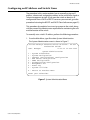
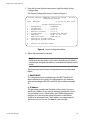
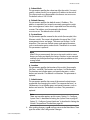
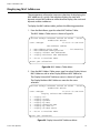
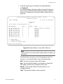
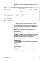
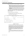
Configuring an IP Address and Switch Name ........................................................................................................................................... 59
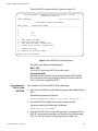
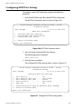
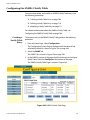
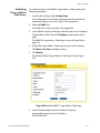
Activating the BOOTP and DHCP Client Software ................................................................................................................................... 62
Rebooting a Switch ............................................................................................................................................................................................. 64
Configuring the Manager and Operator Passwords ............................................................................................................................... 65
Setting the System Time ................................................................................................................................................................................... 67
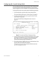
Configuring the Console Startup Mode ...................................................................................................................................................... 71
Configuring the Console Timer ...................................................................................................................................................................... 72
Enabling or Disabling the Telnet Server ...................................................................................................................................................... 73
Setting the Baud Rate of the RS-232 Terminal Port ................................................................................................................................ 74
Pinging a Remote System ................................................................................................................................................................................ 75
Returning the AT-S62 Software to the Factory Default Values ........................................................................................................... 76
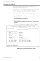
Viewing System Hardware and Software Information .......................................................................................................................... 78
Setting the Switch’s Temperature Threshold ............................................................................................................................................ 80
Chapter 5
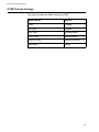
SNMPv1 and SNMPv2c Configuration .................................................................................................................................................... 81
SNMPv1 and SNMPv2c Overview .................................................................................................................................................................. 82
Default SNMP Community Strings ...................................................................................................................................................... 84
Enabling or Disabling SNMP Management ................................................................................................................................................ 85
Setting the Authentication Failure Trap ..................................................................................................................................................... 86
Creating an SNMP Community String ......................................................................................................................................................... 87
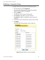
Modifying a Community String ...................................................................................................................................................................... 89
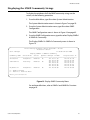
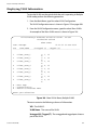
Displaying the SNMP Community Strings .................................................................................................................................................. 93
Chapter 6
Port Parameters ................................................................................................................................................................................................. 94
Displaying Port Status ........................................................................................................................................................................................ 95
Configuring Port Parameters .......................................................................................................................................................................... 98
Setting the Rate Limit ......................................................................................................................................................................................107
Chapter 7
MAC Address Table ........................................................................................................................................................................................109
MAC Address Overview ...................................................................................................................................................................................110
Displaying MAC Addresses ............................................................................................................................................................................112
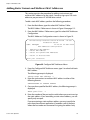
Adding Static Unicast and Multicast MAC Addresses ..........................................................................................................................116
Deleting Unicast and Multicast MAC Addresses ....................................................................................................................................118
Deleting All Dynamic MAC Addresses .......................................................................................................................................................119
Changing the Aging Time ..............................................................................................................................................................................120
Chapter 8
Port Trunking ....................................................................................................................................................................................................121
Port Trunking Overview ..................................................................................................................................................................................122
Port Trunking Guidelines ...................................................................................................................................................................... 122
Port Operating Specifications ............................................................................................................................................................. 123
4
AT-S62 User’s Guide
Load Distribution Methods .................................................................................................................................................................. 123
Creating a Port Trunk ....................................................................................................................................................................................... 129
Modifying a Port Trunk ................................................................................................................................................................................... 132
Deleting a Port Trunk ....................................................................................................................................................................................... 135
Chapter 9
Port Mirroring ................................................................................................................................................................................................... 136
Port Mirroring Overview ................................................................................................................................................................................. 137
Creating a Port Mirror ...................................................................................................................................................................................... 138
Deleting a Port Mirror ...................................................................................................................................................................................... 140
Chapter 10
Ethernet Statistics .......................................................................................................................................................................................... 141
Displaying Port Statistics ................................................................................................................................................................................ 142
Clearing Port Counters .................................................................................................................................................................................... 144
Section II
Advanced Operations ....................................................................................................................... 145
Chapter 11
File System ......................................................................................................................................................................................................... 146
File System Overview ....................................................................................................................................................................................... 147
File Naming Conventions ..................................................................................................................................................................... 148
Working with Boot Configuration Files ..................................................................................................................................................... 149
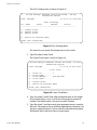
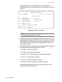
Creating a Boot Configuration File ................................................................................................................................................... 149
Setting the Active Boot Configuration File .................................................................................................................................... 152
Viewing a Boot Configuration File .................................................................................................................................................... 153
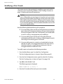
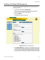
Editing a Boot Configuration File ...................................................................................................................................................... 154
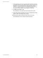
Troubleshooting a Boot Configuration File ................................................................................................................................... 155
Copying, Renaming, and Deleting System Files .................................................................................................................................... 156
Displaying System Files ................................................................................................................................................................................... 158
Chapter 12
File Downloads and Uploads .................................................................................................................................................................... 160
Downloading the AT-S62 Image File onto a Switch ............................................................................................................................. 161
Downloading the AT-S62 Image from a Local Management Session .................................................................................. 162
Downloading the AT-S62 Image from a Telnet Management Session ................................................................................ 165
Downloading an AT-S62 Image File Switch to Switch ......................................................................................................................... 167
Downloading an AT-S62 Configuration File Switch to Switch ......................................................................................................... 169
Downloading a System File ........................................................................................................................................................................... 171
Downloading a System File from a Local Management Session ........................................................................................... 172
Downloading a System File from a Telnet Management Session ......................................................................................... 175
Uploading a System File ................................................................................................................................................................................. 177
Uploading a System File from a Local Management Session .................................................................................................. 178
Uploading a System File from a Telnet Management Session ............................................................................................... 180
Chapter 13
Event Log ............................................................................................................................................................................................................ 182
Event Log Overview ......................................................................................................................................................................................... 183
Enabling or Disabling the Event Log .......................................................................................................................................................... 184
Displaying Events .............................................................................................................................................................................................. 185
Modules ...................................................................................................................................................................................................... 187
Saving the Event Log ....................................................................................................................................................................................... 189
Clearing the Event Log .................................................................................................................................................................................... 190
5
Table of Contents
Chapter 14
Quality of Service ............................................................................................................................................................................................191
Quality of Service Overview ...........................................................................................................................................................................192
Class of Service (CoS) .............................................................................................................................................................................. 192
Scheduling ................................................................................................................................................................................................. 194
Configuring CoS .................................................................................................................................................................................................196
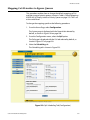
Mapping CoS Priorities to Egress Queues ................................................................................................................................................200
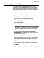
Configuring Egress Scheduling ....................................................................................................................................................................201
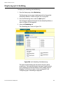
Displaying Port CoS Priorities .......................................................................................................................................................................202
Chapter 15
IGMP Snooping ................................................................................................................................................................................................203
IGMP Snooping Overview ..............................................................................................................................................................................204
Activating IGMP Snooping .............................................................................................................................................................................206
Displaying a List of Host Nodes ....................................................................................................................................................................209
Displaying a List of Multicast Routers ........................................................................................................................................................211
Chapter 16
Denial of Service Defense ...........................................................................................................................................................................212
Denial of Service Defense Overview ...........................................................................................................................................................213
SYN Flood Attack ..................................................................................................................................................................................... 213
SMURF Attack ............................................................................................................................................................................................ 214
Land Attack ................................................................................................................................................................................................ 214
Teardrop Attack ........................................................................................................................................................................................ 215
Ping of Death Attack ............................................................................................................................................................................... 216
IP Options Attack ..................................................................................................................................................................................... 217
Denial of Service Defense Guidelines ............................................................................................................................................... 217
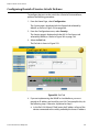
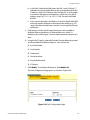
Enabling or Disabling Denial of Service Prevention .............................................................................................................................218
Section III
SNMPv3 Operations ........................................................................................................................... 221
Chapter 17
SNMPv3 Configuration .................................................................................................................................................................................222
SNMPv3 Overview .............................................................................................................................................................................................223
SNMPv3 Authentication Protocols .................................................................................................................................................... 224
SNMPv3 Privacy Protocol ...................................................................................................................................................................... 225
SNMPv3 MIB Views .................................................................................................................................................................................. 225
SNMPv3 Storage Types .......................................................................................................................................................................... 226
SNMPv3 Message Notification ............................................................................................................................................................ 226
SNMPv3 Tables ......................................................................................................................................................................................... 227
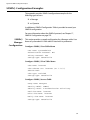
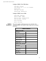
SNMPv3 Configuration Example ........................................................................................................................................................ 232
Configuring the SNMPv3 Protocol ..............................................................................................................................................................233
Configuring the SNMPv3 User Table ..........................................................................................................................................................234
Creating an SNMPv3 User Table Entry ............................................................................................................................................. 234
Deleting an SNMPv3 User Table Entry ............................................................................................................................................. 238
Modifying an SNMPv3 User Table Entry .......................................................................................................................................... 238
Configuring the SNMPv3 View Table .........................................................................................................................................................244
Creating an SNMPv3 View Table Entry ............................................................................................................................................ 244
Deleting an SNMPv3 View Table Entry ............................................................................................................................................ 247
Modifying an SNMPv3 View Table Entry ......................................................................................................................................... 248
Configuring the SNMPv3 Access Table .....................................................................................................................................................253
Creating an SNMPv3 Access Table Entry ......................................................................................................................................... 253
Deleting an SNMPv3 Access Table Entry ......................................................................................................................................... 257
Modifying an SNMPv3 Access Table Entry ..................................................................................................................................... 259
6
AT-S62 User’s Guide
Configuring the SNMPv3 SecurityToGroup Table ................................................................................................................................. 268
Creating an SNMPv3 SecurityToGroup Table Entry .................................................................................................................... 268
Deleting an SNMPv3 SecurityToGroup Table Entry .................................................................................................................... 271
Modifying an SNMPv3 SecurityToGroup Table Entry ................................................................................................................. 272
Configuring the SNMPv3 Notify Table ...................................................................................................................................................... 276
Creating an SNMPv3 Notify Table Entry .......................................................................................................................................... 276
Deleting an SNMPv3 Notify Table Entry .......................................................................................................................................... 278
Modifying an SNMPv3 Notify Table Entry ...................................................................................................................................... 279
Configuring the SNMPv3 Target Address Table .................................................................................................................................... 283
Creating an SNMPv3 Target Address Table Entry ........................................................................................................................ 284
Deleting an SNMPv3 Target Address Table Entry ........................................................................................................................ 286
Modifying an SNMPv3 Target Address Table Entry .................................................................................................................... 287
Configuring the SNMPv3 Target Parameters Table .............................................................................................................................. 296
Creating an SNMPv3 Target Parameters Table Entry ................................................................................................................. 297
Deleting an SNMPv3 Target Parameters Table Entry ................................................................................................................. 300
Modifying an SNMPv3 Target Parameters Table Entry .............................................................................................................. 301
Configuring the SNMPv3 Community Table ........................................................................................................................................... 309
Creating an SNMPv3 Community Table Entry .............................................................................................................................. 310
Deleting an SNMPv3 Community Table Entry .............................................................................................................................. 313
Modifying an SNMPv3 Community Table Entry ........................................................................................................................... 314
Displaying SNMPv3 Table Menus ................................................................................................................................................................ 319
Displaying the Display SNMPv3 User Table Menu ...................................................................................................................... 319
Displaying the Display SNMPv3 View Table Menu ...................................................................................................................... 321
Displaying the Display SNMPv3 Access Table Menu .................................................................................................................. 322
Displaying the Display SNMPv3 SecurityToGroup Table Menu ............................................................................................. 323
Displaying the Display SNMPv3 Notify Table Menu ................................................................................................................... 324
Displaying the Display SNMPv3 Target Address Table Menu ................................................................................................. 325
Displaying the Display SNMPv3 Target Parameters Table Menu ........................................................................................... 326
Displaying the Display SNMPv3 Community Table Menu ....................................................................................................... 327
Section IV
Spanning Tree Protocols
............................................................................................................... 328
Chapter 18
Spanning Tree and Rapid Spanning Tree Protocols ...................................................................................................................... 329
STP and RSTP Overview .................................................................................................................................................................................. 330
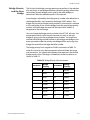
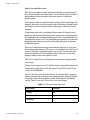
Bridge Priority and the Root Bridge .................................................................................................................................................. 331
Mixed STP and RSTP Network ............................................................................................................................................................. 338
Spanning Tree and VLANs .................................................................................................................................................................... 338
Enabling or Disabling a Spanning Tree Protocol ................................................................................................................................... 340
Configuring STP ................................................................................................................................................................................................. 342
Configuring STP Bridge Settings ........................................................................................................................................................ 342
Configuring STP Port Settings ............................................................................................................................................................ 344
Displaying STP Port Settings ............................................................................................................................................................... 346
Configuring RSTP .............................................................................................................................................................................................. 347
Configuring RSTP Bridge Settings ..................................................................................................................................................... 347
Configuring RSTP Port Settings .......................................................................................................................................................... 349
Displaying Port RSTP Status ................................................................................................................................................................. 351
Chapter 19
Multiple Spanning Tree Protocol ............................................................................................................................................................ 352
MSTP Overview .................................................................................................................................................................................................. 353
Multiple Spanning Tree Instance (MSTI) ......................................................................................................................................... 354
VLAN and MSTI Associations ............................................................................................................................................................... 358
Multiple Spanning Tree Regions ........................................................................................................................................................ 358
7
Table of Contents
Summary of Guidelines ......................................................................................................................................................................... 363
Configuring MSTP Bridge Settings ..............................................................................................................................................................369
Configuring the CIST Priority .........................................................................................................................................................................372
Creating, Deleting, and Modifying MSTI IDs ............................................................................................................................................374
Creating an MSTI ID ................................................................................................................................................................................. 375
Deleting an MSTI ID ................................................................................................................................................................................ 375
Modifying an MSTI ID ............................................................................................................................................................................. 376
Associating VLANs to MSTI IDs .....................................................................................................................................................................377
Associating a VLAN to an MSTI ID ...................................................................................................................................................... 378
Removing a VLAN from an MSTI ID ................................................................................................................................................... 379
Associating VLANs to an MSTI ID and Deleting All Associated VLANs ................................................................................. 379
Configuring MSTP Port Settings ..................................................................................................................................................................380
Displaying MSTP Port Settings and Status ...............................................................................................................................................383
Section V
Virtual LANs ................................................................................................................................................ 384
Chapter 20
Tagged and Port-based Virtual LANs ....................................................................................................................................................385
VLAN Overview ...................................................................................................................................................................................................386
Port-based VLAN Overview ...........................................................................................................................................................................388
General Rules for Creating a Port-based VLAN ............................................................................................................................. 390
Drawbacks of Port-based VLANs ........................................................................................................................................................ 390
Port-based Example 1 ............................................................................................................................................................................ 391
Port-based Example 2 ............................................................................................................................................................................ 393
Tagged VLAN Overview ..................................................................................................................................................................................395
General Rules for Creating a Tagged VLAN .................................................................................................................................... 397
Tagged VLAN Example .......................................................................................................................................................................... 398
Creating a Port-based or Tagged VLAN ....................................................................................................................................................400
Example of Creating a Port-based VLAN ...................................................................................................................................................404
Example of Creating a Tagged VLAN .........................................................................................................................................................405
Modifying a VLAN ..............................................................................................................................................................................................406
Displaying VLANs ..............................................................................................................................................................................................410
Deleting a VLAN .................................................................................................................................................................................................411
Deleting All VLANs ............................................................................................................................................................................................414
Displaying PVIDs and Port Priorities ...........................................................................................................................................................415
Enabling or Disabling Ingress Filtering ......................................................................................................................................................416
Specifying a Management VLAN .................................................................................................................................................................418
Chapter 21
GARP VLAN Registration Protocol ..........................................................................................................................................................420
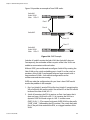
Basic Overview of GARP VLAN Registration Protocol (GVRP) ............................................................................................................421
Guidelines ................................................................................................................................................................................................... 423
GVRP and Network Security ................................................................................................................................................................. 424
GVRP-inactive Intermediate Switches .............................................................................................................................................. 425
Technical Overview of Generic Attribute Registration Protocol (GARP) ..............................................................................................426
Configuring GVRP ..............................................................................................................................................................................................430
Enabling or Disabling GVRP on a Port ........................................................................................................................................................432
Converting a Dynamic GVRP VLAN .............................................................................................................................................................435
Displaying GVRP Parameters and Statistics .............................................................................................................................................436
GVRP Counters .......................................................................................................................................................................................... 437
GVRP Database ......................................................................................................................................................................................... 441
GIP Connected Ports Ring ..................................................................................................................................................................... 442
GVRP State Machine ............................................................................................................................................................................... 443
8
AT-S62 User’s Guide
Chapter 22
Multiple VLAN Modes ................................................................................................................................................................................... 446
Multiple VLAN Mode Overview .................................................................................................................................................................... 447
802.1Q- Compliant Multiple VLAN mode ....................................................................................................................................... 447
Non-802.1Q Compliant Multiple VLAN Mode ............................................................................................................................... 449
Selecting a VLAN Mode ................................................................................................................................................................................... 451
Displaying VLAN Information ....................................................................................................................................................................... 452
Section VI
Port Security
............................................................................................................................................... 453
Chapter 23
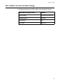
MAC Address Security .................................................................................................................................................................................. 454
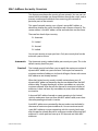
MAC Address Security Overview ................................................................................................................................................................. 455
Automatic ................................................................................................................................................................................................... 455
Limited ........................................................................................................................................................................................................ 455
Secured ....................................................................................................................................................................................................... 456
Locked ......................................................................................................................................................................................................... 456
Security Violations and Intrusion Actions ....................................................................................................................................... 456
Guidelines .................................................................................................................................................................................................. 457
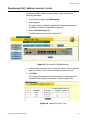
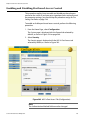
Configuring MAC Address Port Security ................................................................................................................................................... 458
Displaying Port Security Levels .................................................................................................................................................................... 461
Chapter 24
802.1x Port-based Access Control .......................................................................................................................................................... 463
802.1x Port-based Access Control Overview .......................................................................................................................................... 464
Authentication Process ......................................................................................................................................................................... 465
Port Roles .................................................................................................................................................................................................... 466
RADIUS Accounting ................................................................................................................................................................................ 468
General Steps ............................................................................................................................................................................................ 469
Port-based Access Control Guidelines ............................................................................................................................................. 470
Enabling and Disabling Port-based Access Control ............................................................................................................................. 473
Setting Port Roles .............................................................................................................................................................................................. 474
Configuring Authenticator Port Parameters ........................................................................................................................................... 476
Configuring Supplicant Port Parameters ................................................................................................................................................. 480
Configuring RADIUS Accounting ................................................................................................................................................................ 483
Section VII
Management Security
...................................................................................................................... 485
Chapter 25
Web Server ......................................................................................................................................................................................................... 486
Web Server Overview ...................................................................................................................................................................................... 487
Supported Protocols .............................................................................................................................................................................. 487
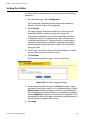
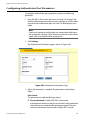
General Steps to Configuring the Web Server for Encryption ................................................................................................ 488
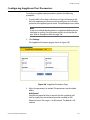
Configuring the Web Server .......................................................................................................................................................................... 490
Chapter 26
Encryption Keys ............................................................................................................................................................................................... 492
Basic Overview ................................................................................................................................................................................................... 493
Encryption Key Length .......................................................................................................................................................................... 494
Encryption Key Guidelines ................................................................................................................................................................... 494
Technical Overview .......................................................................................................................................................................................... 495
Data Encryption ....................................................................................................................................................................................... 495
9
Table of Contents
Data Authentication ............................................................................................................................................................................... 497
Key Exchange Algorithms ..................................................................................................................................................................... 498
Creating an Encryption Key ...........................................................................................................................................................................500
Deleting an Encryption Key ...........................................................................................................................................................................504
Modifying an Encryption Key ........................................................................................................................................................................505
Exporting an Encryption Key .........................................................................................................................................................................506
Importing an Encryption Key ........................................................................................................................................................................508
Chapter 27
Public Key Infrastructure Certificates ...................................................................................................................................................510
Basic Overview ...................................................................................................................................................................................................511
Types of Certificates ................................................................................................................................................................................ 511
Distinguished Names ............................................................................................................................................................................. 512
SSL and Enhanced Stacking ................................................................................................................................................................. 514
Guidelines ................................................................................................................................................................................................... 515
Technical Overview ...........................................................................................................................................................................................516
SSL Encryption .......................................................................................................................................................................................... 516
User Verification ....................................................................................................................................................................................... 517
Authentication .......................................................................................................................................................................................... 518
Public Key Infrastructure ....................................................................................................................................................................... 518
Public Keys ................................................................................................................................................................................................. 518
Message Encryption ................................................................................................................................................................................ 518
Digital Signatures .................................................................................................................................................................................... 519
Certificates .................................................................................................................................................................................................. 519
Elements of a Public Key Infrastructure ........................................................................................................................................... 520
Certificate Validation .............................................................................................................................................................................. 521
Certificate Revocation Lists (CRLs) ..................................................................................................................................................... 522
PKI Implementation ................................................................................................................................................................................ 522
Creating a Self-signed Certificate ................................................................................................................................................................524
Adding a Certificate to the Database .........................................................................................................................................................528
Modifying a Certificate ....................................................................................................................................................................................531
Deleting a Certificate .......................................................................................................................................................................................533
Viewing a Certificate ........................................................................................................................................................................................534
Generating an Enrollment Request ............................................................................................................................................................537
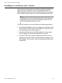
Installing CA Certificates onto a Switch ....................................................................................................................................................540
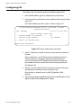
Configuring PKI ..................................................................................................................................................................................................541
Configuring SSL ..................................................................................................................................................................................................542
Chapter 28
Secure Shell (SSH) Protocol ........................................................................................................................................................................543
SSH Overview ......................................................................................................................................................................................................544
Support for SSH ........................................................................................................................................................................................ 544
SSH Server .................................................................................................................................................................................................. 545
SSH Clients ................................................................................................................................................................................................. 545
SSH and Enhanced Stacking ................................................................................................................................................................ 546
Guidelines ................................................................................................................................................................................................... 547
General Steps to Configuring SSH ..................................................................................................................................................... 547
Configuring the SSH Server ...........................................................................................................................................................................548
Displaying SSH Information ...........................................................................................................................................................................550
Chapter 29
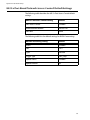
RADIUS and TACACS+ Authentication Protocols ............................................................................................................................552
TACACS+ and RADIUS Overview .................................................................................................................................................................553
Guidelines ................................................................................................................................................................................................... 554
Configuring Authentication Protocol Settings .......................................................................................................................................557
Displaying RADIUS Status and Settings ........................................................................................................................................... 562
10
AT-S62 User’s Guide
Chapter 30
Management Access Control List ............................................................................................................................................................ 563
Management Access Control List Overview ............................................................................................................................................ 564
Parts of a Management ACE ................................................................................................................................................................ 564
Management ACL Guidelines ............................................................................................................................................................. 565
Management ACL Examples ............................................................................................................................................................... 566
Creating the Management ACL ................................................................................................................................................................... 568
Adding, Deleting, and Viewing ACEs ......................................................................................................................................................... 570
Section VIII
Web Browser Management
........................................................................................................ 571
Chapter 31
Starting a Web Browser Management Session ................................................................................................................................ 573
Starting a Web Browser Management Session ...................................................................................................................................... 574
Browser Tools ............................................................................................................................................................................................ 576
Saving Your Parameter Changes ................................................................................................................................................................. 577
Quitting a Web Browser Management Session ..................................................................................................................................... 578
Chapter 32
Enhanced Stacking ......................................................................................................................................................................................... 579
Setting a Switch’s Enhanced Stacking Status ......................................................................................................................................... 580
Selecting a Switch in an Enhanced Stack ................................................................................................................................................. 582
Returning to the Master Switch ......................................................................................................................................................... 583
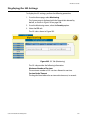
Displaying the Enhanced Stacking Status ................................................................................................................................................ 584
Chapter 33
Basic Switch Parameters ............................................................................................................................................................................. 585
Configuring an IP Address and Switch Name ......................................................................................................................................... 586
Activating the BOOTP and DHCP Client Software ................................................................................................................................. 589
Displaying System Information .................................................................................................................................................................... 590
Configuring the Manager and Operator Passwords ............................................................................................................................ 592
Rebooting a Switch .......................................................................................................................................................................................... 594
Pinging a Remote System .............................................................................................................................................................................. 595
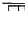
Returning the AT-S62 Software to the Factory Default Values ......................................................................................................... 596
Chapter 34
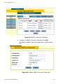
SNMPv1 and SNMPv2c Community Strings ...................................................................................................................................... 598
Enabling or Disabling SNMP Management ............................................................................................................................................. 599
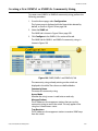
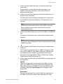
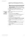
Creating a New SNMPv1 or SNMPv2c Community String .................................................................................................................. 601
Modifying a Community String ................................................................................................................................................................... 604
Deleting a Community String ....................................................................................................................................................................... 606
Displaying the SNMP Status and Community Strings ......................................................................................................................... 607
Chapter 35
Port Parameters ............................................................................................................................................................................................... 609
Configuring Port Parameters ........................................................................................................................................................................ 610
Displaying Port Status and Statistics .......................................................................................................................................................... 616
Chapter 36
MAC Address Table ........................................................................................................................................................................................ 621
Displaying the MAC Address Table ............................................................................................................................................................ 622
Adding Static Unicast and Multicast MAC Addresses .......................................................................................................................... 624
Deleting Unicast and Multicast MAC Addresses .................................................................................................................................... 626
Changing the Aging Time .............................................................................................................................................................................. 627
11
Table of Contents
Chapter 37
Port Trunking ....................................................................................................................................................................................................628
Creating a Port Trunk .......................................................................................................................................................................................629
Modifying a Port Trunk ....................................................................................................................................................................................632
Deleting a Port Trunk .......................................................................................................................................................................................634
Displaying the Port Trunks .............................................................................................................................................................................635
Chapter 38
Port Mirroring ...................................................................................................................................................................................................637
Creating a Port Mirror ......................................................................................................................................................................................638
Modifying or Disabling a Port Mirror ..........................................................................................................................................................641
Deleting a Port Mirror ......................................................................................................................................................................................642
Displaying the Port Mirror ..............................................................................................................................................................................643
Chapter 39
File Downloads and Uploads .....................................................................................................................................................................644
Downloading a File ...........................................................................................................................................................................................645
Uploading a File .................................................................................................................................................................................................648
Chapter 40
Event Log ............................................................................................................................................................................................................650
Enabling or Disabling the Event Log ..........................................................................................................................................................651
Displaying Events ..............................................................................................................................................................................................653
Saving the Event Log .......................................................................................................................................................................................655
Clearing the Event Log ....................................................................................................................................................................................656
Chapter 41
Quality of Service ............................................................................................................................................................................................657
Configuring CoS .................................................................................................................................................................................................658
Mapping CoS Priorities to Egress Queues ................................................................................................................................................661
Configuring Egress Scheduling ....................................................................................................................................................................663
Displaying the CoS Settings ..........................................................................................................................................................................664
Displaying QoS Scheduling ...........................................................................................................................................................................666
Chapter 42
IGMP Snooping ................................................................................................................................................................................................667
Configuring IGMP Snooping .........................................................................................................................................................................668
Displaying a List of Host Nodes and Multicast Routers .......................................................................................................................671
Chapter 43
Denial of Service Defense ...........................................................................................................................................................................673
Configuring Denial of Service Attack Defense ........................................................................................................................................674
Displaying the DoS Settings ..........................................................................................................................................................................677
Chapter 44
SNMPv3 Protocol ............................................................................................................................................................................................678
Configuring the SNMPv3 Protocol ..............................................................................................................................................................679
Enabling the SNMP Protocol .........................................................................................................................................................................680
Configuring the SNMPv3 User Table ..........................................................................................................................................................683
Creating a User Table Entry .................................................................................................................................................................. 683
Deleting a User Table Entry .................................................................................................................................................................. 686
Modifying a User Table Entry .............................................................................................................................................................. 686
Configuring the SNMPv3 View Table .........................................................................................................................................................690
Creating a View Table Entry ................................................................................................................................................................. 690
Deleting a View Table Entry ................................................................................................................................................................. 693
Modifying a View Table Entry .............................................................................................................................................................. 694
12
AT-S62 User’s Guide
Configuring the SNMPv3 Access Table ..................................................................................................................................................... 696
Creating an Access Table ...................................................................................................................................................................... 696
Deleting an Access Table Entry .......................................................................................................................................................... 700
Modifying an Access Table Entry ....................................................................................................................................................... 701
Configuring the SNMPv3 SecurityToGroup Table ................................................................................................................................. 703
Creating a SecurityToGroup Table Entry ........................................................................................................................................ 703
Deleting a SecurityToGroup Table Entry ........................................................................................................................................ 705
Modifying a SecurityToGroup Table Entry ..................................................................................................................................... 706
Configuring the SNMPv3 Notify Table ...................................................................................................................................................... 708
Creating a Notify Table Entry .............................................................................................................................................................. 708
Deleting a Notify Table Entry .............................................................................................................................................................. 710
Modifying a Notify Table Entry ........................................................................................................................................................... 711
Configuring the SNMPv3 Target Address Table .................................................................................................................................... 713
Creating a Target Address Table Entry ............................................................................................................................................ 713
Deleting a Target Address Table Entry ............................................................................................................................................ 716
Modifying Target Address Table Entry ............................................................................................................................................ 717
Configuring the SNMPv3 Target Parameters Table .............................................................................................................................. 720
Creating a Target Parameters Table Entry ...................................................................................................................................... 720
Deleting a Target Parameters Table Entry ...................................................................................................................................... 723
Modifying a Target Parameters Table Entry .................................................................................................................................. 724
Configuring the SNMPv3 Community Table ........................................................................................................................................... 727
Creating an SNMPv3 Community Table Entry .............................................................................................................................. 727
Deleting an SNMPv3 Community Table Entry .............................................................................................................................. 730
Modifying an SNMPv3 Community Table Entry ........................................................................................................................... 731
Displaying SNMPv3 Tables ............................................................................................................................................................................ 733
Displaying User Table Entries .............................................................................................................................................................. 734
Displaying View Table Entries ............................................................................................................................................................. 735
Displaying Access Table Entries ......................................................................................................................................................... 736
Displaying SecurityToGroup Table Entries ..................................................................................................................................... 737
Displaying Notify Table Entries .......................................................................................................................................................... 738
Displaying Target Address Table Entries ........................................................................................................................................ 739
Displaying Target Parameters Table Entries .................................................................................................................................. 740
Displaying SNMPv3 Community Table Entries ............................................................................................................................. 741
Chapter 45
STP, RSTP, and MSTP ..................................................................................................................................................................................... 742
Enabling or Disabling Spanning Tree ........................................................................................................................................................ 743
Configuring STP ................................................................................................................................................................................................. 745
Configuring RSTP .............................................................................................................................................................................................. 748
Configuring MSTP ............................................................................................................................................................................................. 752
Configuring MSTP and CIST Parameters ......................................................................................................................................... 752
Associating VLANs to MSTIs ................................................................................................................................................................ 755
Configuring MSTP Port Parameters .................................................................................................................................................. 758
Displaying Spanning Tree Settings ............................................................................................................................................................ 760
Chapter 46
Virtual LANs ....................................................................................................................................................................................................... 761
Creating a New Port-Based or Tagged VLAN .......................................................................................................................................... 762
Modifying a Port-Based or Tagged VLAN ................................................................................................................................................. 766
Deleting a Port-Based or Tagged VLAN .................................................................................................................................................... 768
Displaying VLANs .............................................................................................................................................................................................. 769
Selecting a VLAN Mode ................................................................................................................................................................................... 771
Specifying a Management VLAN ................................................................................................................................................................. 773
13
Table of Contents
Chapter 47
GARP VLAN Registration Protocol ..........................................................................................................................................................775
Configuring GVRP ..............................................................................................................................................................................................776
Enabling or Disabling GVRP on a Port ........................................................................................................................................................778
Displaying the GVRP Settings .......................................................................................................................................................................780
Chapter 48
MAC Address Security ...................................................................................................................................................................................782
Displaying MAC Address Security Levels ..................................................................................................................................................783
Chapter 49
802.1x Port-based Access Control ..........................................................................................................................................................785
Enabling and Disabling Port-based Access Control .............................................................................................................................786
Setting Port Roles ..............................................................................................................................................................................................788
Configuring Authenticator Port Parameters ...........................................................................................................................................790
Configuring Supplicant Port Parameters ..................................................................................................................................................793
Displaying the Port-based Access Control Settings ..............................................................................................................................795
Chapter 50
Secure Shell Protocol ....................................................................................................................................................................................797
Configuring the SSH Server ...........................................................................................................................................................................798
Displaying SSH Information ...........................................................................................................................................................................800
Chapter 51
Encryption Keys, PKI, and SSL ...................................................................................................................................................................802
Displaying Encryption Keys ...........................................................................................................................................................................803
Displaying PKI Settings and Certificates ...................................................................................................................................................804
Displaying the SSL Settings ...........................................................................................................................................................................807
Chapter 52
RADIUS and TACACS+ Authentication Protocols ............................................................................................................................808
Configuring RADIUS and TACACS+ ............................................................................................................................................................809
Displaying the RADIUS or TACSACS+ Settings .......................................................................................................................................813
Chapter 53
Management Access Control List ............................................................................................................................................................815
Creating a Management ACL ........................................................................................................................................................................816
Adding or Deleting an ACE ............................................................................................................................................................................818
Displaying the Management ACL ................................................................................................................................................................819
Appendix A
AT-S62 Default Settings ...............................................................................................................................................................................820
Basic Switch Default Settings ........................................................................................................................................................................821
Boot Configuration File Default Setting .......................................................................................................................................... 821
Management Access Default Settings ............................................................................................................................................. 821
Management Interface Default Settings ......................................................................................................................................... 821
RS-232 Port Default Settings ............................................................................................................................................................... 822
SNTP Default Settings ............................................................................................................................................................................ 822
Switch Administration Default Settings .......................................................................................................................................... 823
System Software Default Settings ..................................................................................................................................................... 823
Enhanced Stacking Default Setting ............................................................................................................................................................824
SNMP Default Settings ....................................................................................................................................................................................825
Port Configuration Default Settings ...........................................................................................................................................................826
Event Log Default Settings ............................................................................................................................................................................827
Quality of Service ...............................................................................................................................................................................................828
IGMP Snooping Default Settings .................................................................................................................................................................829
14
AT-S62 User’s Guide
Denial of Service Prevention Default Settings ........................................................................................................................................ 830
STP, RSTP, and MSTP Default Settings ....................................................................................................................................................... 831
Spanning Tree Switch Settings ........................................................................................................................................................... 831
STP Default Settings ............................................................................................................................................................................... 831
RSTP Default Settings ............................................................................................................................................................................ 831
MSTP Default Settings ........................................................................................................................................................................... 832
VLAN Default Settings ..................................................................................................................................................................................... 833
GVRP Default Settings ..................................................................................................................................................................................... 834
MAC Address Security Default Settings .................................................................................................................................................... 835
802.1x Port-Based Network Access Control Default Settings ........................................................................................................... 836
Web Server Default Settings ......................................................................................................................................................................... 837
SSL Default Settings ......................................................................................................................................................................................... 838
PKI Default Settings .......................................................................................................................................................................................... 839
SSH Default Settings ........................................................................................................................................................................................ 840
Server-Based Authentication Default Settings ....................................................................................................................................... 841
Server-Based Authentication Default Settings ............................................................................................................................. 841
RADIUS Default Settings ....................................................................................................................................................................... 841
TACACS+ Client Default Settings ...................................................................................................................................................... 841
Management Access Control List Default Setting ................................................................................................................................ 842
Appendix B
SNMPv3 Configuration Examples ........................................................................................................................................................... 843
SNMPv3 Configuration Examples ............................................................................................................................................................... 844
SNMPv3 Manager Configuration ....................................................................................................................................................... 844
SNMPv3 Operator Configuration ....................................................................................................................................................... 845
SNMPv3 Worksheet ................................................................................................................................................................................ 846
Index ......................................................................................................................................................................... 849
15
List of Figures
Chapter 1
Overview ................................................................................................................................................................................................................31
Chapter 2
Starting a Local or Telnet Management Session ................................................................................................................................40
Figure 1: Connecting a Terminal or PC to the RS232 Terminal Port ................................................................................................. 42
Figure 2: Command Prompt ............................................................................................................................................................................ 43
Figure 3: Main Menu .......................................................................................................................................................................................... 43
Chapter 3
Enhanced Stacking ...........................................................................................................................................................................................48
Figure 4: Enhanced Stacking Example ........................................................................................................................................................ 51
Figure 5: Enhanced Stacking Menu .............................................................................................................................................................. 53
Figure 6: Stacking Services Menu .................................................................................................................................................................. 54
Chapter 4
Basic Switch Parameters ................................................................................................................................................................................56
Figure 7: System Administration Menu ....................................................................................................................................................... 59
Figure 8: System Configuration Menu ......................................................................................................................................................... 60
Figure 9: System Utilities Menu ...................................................................................................................................................................... 64
Figure 10: Passwords Configuration Menu ................................................................................................................................................ 65
Figure 11: Configure System Time Menu ................................................................................................................................................... 68
Figure 12: Console (Serial/Telnet) Configuration Menu ........................................................................................................................ 71
Figure 13: System Information Menu .......................................................................................................................................................... 78
Figure 14: System Hardware Information Menu ...................................................................................................................................... 79
Figure 15: Configure System Hardware Menu ......................................................................................................................................... 80
Chapter 5
SNMPv1 and SNMPv2c Configuration .....................................................................................................................................................81
Figure 16: SNMP Configuration Menu ......................................................................................................................................................... 85
Figure 17: SNMPv1 & SNMPv2c Community Menu ................................................................................................................................ 87
Figure 18: Modify SNMP Community Menu .............................................................................................................................................. 89
Figure 19: Display SNMP Community Menu ............................................................................................................................................. 93
Chapter 6
Port Parameters .................................................................................................................................................................................................94
Figure 20: Port Configuration Menu ............................................................................................................................................................ 95
Figure 21: Port Status Menu ............................................................................................................................................................................ 95
Figure 22: Port Configuration (Port) Menu ................................................................................................................................................ 98
Figure 23: Manual Speed and Duplex Mode Settings ........................................................................................................................ 101
16
AT-S62 User’s Guide
Figure 24: Head of Line Blocking ................................................................................................................................................................
Figure 25: Flow Control Menu .....................................................................................................................................................................
Figure 26: Back Pressure Menu ...................................................................................................................................................................
Figure 27: Rate Limiting Menu ....................................................................................................................................................................
102
103
105
108
Chapter 7
MAC Address Table ........................................................................................................................................................................................ 109
Figure 28: MAC Address Tables Menu ...................................................................................................................................................... 112
Figure 29: Display Unicast MAC Addresses Menu ................................................................................................................................ 112
Figure 30: Display All Menu - Unicast MAC Addresses ....................................................................................................................... 113
Figure 31: Display All Menu - Multicast MAC Addresses .................................................................................................................... 114
Figure 32: Configure MAC Addresses Menu ........................................................................................................................................... 116
Chapter 8
Port Trunking ................................................................................................................................................................................................... 121
Figure 33: Port Trunk Example .................................................................................................................................................................... 122
Figure 34: Load Distribution Method ....................................................................................................................................................... 125
Figure 35: Port Trunking Menu ................................................................................................................................................................... 130
Figure 36: Create Trunk Menu ..................................................................................................................................................................... 130
Figure 37: Modify Trunk Menu .................................................................................................................................................................... 133
Chapter 9
Port Mirroring ................................................................................................................................................................................................... 136
Figure 38: Port Mirroring Menu #1 ............................................................................................................................................................. 138
Figure 39: Port Mirroring Menu #2 ............................................................................................................................................................. 138
Chapter 10
Ethernet Statistics .......................................................................................................................................................................................... 141
Figure 40: Port Statistics Menu .................................................................................................................................................................... 142
Chapter 11
File System ......................................................................................................................................................................................................... 146
Figure 41: File Operations Menu ................................................................................................................................................................ 150
Figure 42: View File Menu ............................................................................................................................................................................. 154
Figure 43: List Files Menu .............................................................................................................................................................................. 159
Chapter 12
File Downloads and Uploads .................................................................................................................................................................... 160
Figure 44: Downloads and Uploads Menu .............................................................................................................................................. 162
Figure 45: Local Management Window ................................................................................................................................................... 164
Figure 46: Send File Window ....................................................................................................................................................................... 164
Figure 47: XModem File Send Window .................................................................................................................................................... 165
Figure 48: Local Management Window ................................................................................................................................................... 174
Figure 49: Send File Window ....................................................................................................................................................................... 174
Figure 50: XModem File Send Window .................................................................................................................................................... 175
Figure 51: Local Management Window ................................................................................................................................................... 180
Figure 52: Receive File Window .................................................................................................................................................................. 180
Chapter 13
Event Log ............................................................................................................................................................................................................ 182
Figure 53: Event Log Menu ........................................................................................................................................................................... 184
Figure 54: Event Log Example ..................................................................................................................................................................... 186
Chapter 14
Quality of Service ............................................................................................................................................................................................ 191
Figure 55: Security and Services Menu ..................................................................................................................................................... 196
Figure 56: Class of Service (CoS) Menu ..................................................................................................................................................... 197
Figure 57: Configure Port COS Priorities Menu ..................................................................................................................................... 198
Figure 58: Map CoS Priority to Egress Queue Menu ............................................................................................................................ 200
Figure 59: Configure Egress Scheduling Menu ..................................................................................................................................... 201
17
List of Figures
Figure 60: Show Port CoS Priorities Menu ............................................................................................................................................... 202
Chapter 15
IGMP Snooping ................................................................................................................................................................................................203
Figure 61: Advanced Configuration Menu .............................................................................................................................................. 206
Figure 62: IGMP Snooping Configuration Menu ................................................................................................................................... 206
Figure 63: View Multicast Hosts List Menu .............................................................................................................................................. 209
Figure 64: View Multicast Routers List Menu .......................................................................................................................................... 211
Chapter 16
Denial of Service Defense ...........................................................................................................................................................................212
Figure 65: Denial of Service (DoS) Menu .................................................................................................................................................. 218
Figure 66: LAN IP Subnet Menu ................................................................................................................................................................... 219
Figure 67: SYN Flood Configuration Menu ............................................................................................................................................. 220
Chapter 17
SNMPv3 Configuration ................................................................................................................................................................................222
Figure 68: MIB Tree .......................................................................................................................................................................................... 225
Figure 69: SNMPv3 User Configuration Process .................................................................................................................................... 228
Figure 70: SNMPv3 Message Notification Process ................................................................................................................................ 229
Figure 71: Configure SNMPv3 Table Menu ............................................................................................................................................. 235
Figure 72: Configure SNMPv3 User Table Menu ................................................................................................................................... 235
Figure 73: Modify SNMPv3 User Table Menu ......................................................................................................................................... 239
Figure 74: Configure SNMPv3 View Table Menu .................................................................................................................................. 245
Figure 75: Modify SNMPv3 View Table Menu ........................................................................................................................................ 249
Figure 76: Configure SNMPv3 Access Table Menu ............................................................................................................................... 254
Figure 77: Modify SNMPv3 Access Table Menu ..................................................................................................................................... 260
Figure 78: Configure SNMPv3 SecurityToGroup Table Menu .......................................................................................................... 269
Figure 79: Modify SNMPv3 SecurityToGroup Table Menu ................................................................................................................ 273
Figure 80: Configure SNMPv3 Notify Table Menu ................................................................................................................................ 277
Figure 81: Modify SNMPv3 Notify Table Menu ...................................................................................................................................... 280
Figure 82: Configure SNMPv3 Target Address Table Menu .............................................................................................................. 284
Figure 83: Modify SNMPv3 Target Address Table Menu .................................................................................................................... 288
Figure 84: Configure SNMPv3 Target Parameters Table Menu ....................................................................................................... 297
Figure 85: Modify SNMPv3 Target Parameters Table Menu ............................................................................................................. 303
Figure 86: Configure SNMPv3 Community Table Menu .................................................................................................................... 311
Figure 87: Modify SNMPv3 Community Table Menu .......................................................................................................................... 315
Figure 88: Display SNMPv3 Table Menu ................................................................................................................................................... 320
Figure 89: Display SNMPv3 User Table Menu ......................................................................................................................................... 320
Figure 90: Display SNMPv3 View Table Menu ........................................................................................................................................ 321
Figure 91: Display SNMPv3 Access Table Menu .................................................................................................................................... 322
Figure 92: Display SNMPv3 SecurityToGroup Table Menu ................................................................................................................ 323
Figure 93: Display SNMPv3 Notify Table Menu ..................................................................................................................................... 324
Figure 94: Display SNMPv3 Target Address Table Menu ................................................................................................................... 325
Figure 95: Display SNMPv3 Target Parameters Table Menu ............................................................................................................. 326
Figure 96: Display SNMPv3 Community Table Menu .......................................................................................................................... 327
Chapter 18
Spanning Tree and Rapid Spanning Tree Protocols ......................................................................................................................329
Figure 97: Point-to-Point Ports .................................................................................................................................................................... 336
Figure 98: Edge Port ........................................................................................................................................................................................ 337
Figure 99: Point-to-Point and Edge Port .................................................................................................................................................. 337
Figure 100: VLAN Fragmentation ............................................................................................................................................................... 338
Figure 101: Spanning Tree Configuration Menu ................................................................................................................................... 340
Figure 102: STP Menu ..................................................................................................................................................................................... 342
Figure 103: STP Port Parameters Menu .................................................................................................................................................... 344
Figure 104: Configure STP Port Settings Menu ..................................................................................................................................... 345
Figure 105: Display STP Port Configuration Menu ............................................................................................................................... 346
18
AT-S62 User’s Guide
Figure 106: RSTP Menu .................................................................................................................................................................................. 347
Figure 107: RSTP Port Parameters Menu ................................................................................................................................................. 349
Figure 108: Configure RSTP Port Settings Menu .................................................................................................................................. 350
Chapter 19
Multiple Spanning Tree Protocol ............................................................................................................................................................ 352
Figure 109: VLAN Fragmentation with STP or RSTP ............................................................................................................................ 355
Figure 110: MSTP Example of Two Spanning Tree Instances .......................................................................................................... 356
Figure 111: Multiple VLANs in a MSTI ...................................................................................................................................................... 357
Figure 112: Multiple Spanning Tree Region ........................................................................................................................................... 360
Figure 113: CIST and VLAN Guideline - Example 1 ............................................................................................................................... 365
Figure 114: CIST and VLAN Guideline - Example 2 ............................................................................................................................... 366
Figure 115: Spanning Regions - Example 1 ............................................................................................................................................ 367
Figure 116: MSTP Menu ................................................................................................................................................................................. 369
Figure 117: CIST Menu .................................................................................................................................................................................... 372
Figure 118: MSTI Menu ................................................................................................................................................................................... 374
Figure 119: VLAN-MSTI Association Menu .............................................................................................................................................. 378
Figure 120: MSTP Port Parameters Menu ................................................................................................................................................ 380
Figure 121: Configure MSTP Port Settings Menu ................................................................................................................................. 380
Chapter 20
Tagged and Port-based Virtual LANs ................................................................................................................................................... 385
Figure 122: Port-based VLAN - Example 1 ............................................................................................................................................... 391
Figure 123: Port-based VLAN - Example 2 ............................................................................................................................................... 393
Figure 124: Example of a Tagged VLAN ................................................................................................................................................... 398
Figure 125: VLAN Configuration Menu .................................................................................................................................................... 400
Figure 126: Configure VLANs Menu .......................................................................................................................................................... 401
Figure 127: Create VLAN Menu ................................................................................................................................................................... 401
Figure 128: Modify VLAN Menu .................................................................................................................................................................. 406
Figure 129: Expanded Modify VLAN Menu ............................................................................................................................................. 407
Figure 130: Show VLANs Menu ................................................................................................................................................................... 410
Figure 131: Delete VLAN Menu ................................................................................................................................................................... 411
Figure 132: Expanded Delete VLAN Menu .............................................................................................................................................. 412
Figure 133: Show PVIDs & Priorities Menu .............................................................................................................................................. 415
Chapter 21
GARP VLAN Registration Protocol ......................................................................................................................................................... 420
Figure 134: GVRP Example ........................................................................................................................................................................... 422
Figure 135: GARP Architecture ................................................................................................................................................................... 427
Figure 136: GID Architecture ....................................................................................................................................................................... 428
Figure 137: GARP-GVRP Menu ..................................................................................................................................................................... 430
Figure 138: GVRP Port Parameters Menu ................................................................................................................................................ 432
Figure 139: Configure GVRP Port Settings Menu ................................................................................................................................. 433
Figure 140: Display GVRP Port Configuration Menu ........................................................................................................................... 433
Figure 141: Other GARP Port Parameters Menu ................................................................................................................................... 436
Figure 142: GVRP Counters Menu (page 1) ............................................................................................................................................. 437
Figure 143: GVRP Counters Menu (page 2) ............................................................................................................................................. 438
Figure 144: GVRP Database Menu ............................................................................................................................................................. 441
Figure 145: GIP Connected Ports Ring Menu ......................................................................................................................................... 442
Figure 146: GVRP State Machine Menu (page 1) .................................................................................................................................. 443
Figure 147: Display GVRP State Machine Menu (page 2) .................................................................................................................. 443
Chapter 22
Multiple VLAN Modes ................................................................................................................................................................................... 446
Figure 148: Show VLANs Menu, Multiple VLANS .................................................................................................................................. 452
19
List of Figures
Chapter 23
MAC Address Security ...................................................................................................................................................................................454
Figure 149: Port Security Menu ................................................................................................................................................................... 458
Figure 150: Configure Port Security Menu #1 ........................................................................................................................................ 458
Figure 151: Configure Port Security Menu #2 ........................................................................................................................................ 459
Figure 152: Display Port Security Menu ................................................................................................................................................... 461
Chapter 24
802.1x Port-based Access Control ..........................................................................................................................................................463
Figure 153: Example of the Authenticator Role .................................................................................................................................... 467
Figure 154: Example of the Supplicant Role ........................................................................................................................................... 468
Figure 155: Port-based Authentication Across Multiple Switches ................................................................................................. 472
Figure 156: Port Access Control (802.1X) Menu .................................................................................................................................... 473
Figure 157: Configure Port Access Role Menu ....................................................................................................................................... 474
Figure 158: Configure Authenticator Menu ............................................................................................................................................ 476
Figure 159: Configure Authenticator Port Access Parameters Menu ............................................................................................ 477
Figure 160: Configure Supplicant Menu .................................................................................................................................................. 480
Figure 161: Configure Supplicant Port Access Parameters Menu .................................................................................................. 481
Figure 162: Radius Accounting Menu ....................................................................................................................................................... 483
Chapter 25
Web Server .........................................................................................................................................................................................................486
Figure 163: Web Server Configuration Menu ......................................................................................................................................... 490
Chapter 26
Encryption Keys ...............................................................................................................................................................................................492
Figure 164: Keys/Certificate Configuration Menu ................................................................................................................................ 500
Figure 165: Key Management Menu ......................................................................................................................................................... 501
Figure 166: Create Key Menu ....................................................................................................................................................................... 502
Figure 167: Export Key to File Menu .......................................................................................................................................................... 506
Figure 168: Import Key From File Menu ................................................................................................................................................... 508
Chapter 27
Public Key Infrastructure Certificates ...................................................................................................................................................510
Figure 169: Public Key Infrastructure (PKI) Configuration Menu .................................................................................................... 525
Figure 170: X509 Certificate Management Menu ................................................................................................................................. 525
Figure 171: Create Self-Signed Certificate Menu .................................................................................................................................. 526
Figure 172: Add Certificate Menu ............................................................................................................................................................... 528
Figure 173: Modify Certificate Menu ......................................................................................................................................................... 531
Figure 174: View Certificate Details Menu (page 1) ............................................................................................................................. 534
Figure 175: View Certificate Details Menu (page 2) ............................................................................................................................. 535
Figure 176: Generate Enrollment Request Menu ................................................................................................................................. 538
Figure 177: Secure Socket Layer (SSL) Menu .......................................................................................................................................... 542
Chapter 28
Secure Shell (SSH) Protocol ........................................................................................................................................................................543
Figure 178: SSH Remote Management of a Slave Switch .................................................................................................................. 546
Figure 179: Secure Shell (SSH) Menu ......................................................................................................................................................... 548
Figure 180: Show Server Information Menu ........................................................................................................................................... 550
Chapter 29
RADIUS and TACACS+ Authentication Protocols ............................................................................................................................552
Figure 181: Authentication Menu .............................................................................................................................................................. 557
Figure 182: TACACS+ Client Configuration Menu ................................................................................................................................ 558
Figure 183: RADIUS Client Configuration ................................................................................................................................................ 560
Figure 184: RADIUS Server Configuration ............................................................................................................................................... 561
Figure 185: Show Status Menu .................................................................................................................................................................... 562
20
AT-S62 User’s Guide
Chapter 30
Management Access Control List ............................................................................................................................................................ 563
Figure 186: Management ACL Menu ........................................................................................................................................................ 568
Chapter 31
Starting a Web Browser Management Session ................................................................................................................................ 573
Figure 187: Entering a Switch’s IP Address in the URL Field ............................................................................................................. 574
Figure 188: AT-S62 Login Page ................................................................................................................................................................... 575
Figure 189: Home Page .................................................................................................................................................................................. 575
Figure 190: Save Changes Button in the General Tab (Configuration) ......................................................................................... 577
Chapter 32
Enhanced Stacking ........................................................................................................................................................................................ 579
Figure 191: Enhanced Stacking Tab (Configuration) .......................................................................................................................... 581
Figure 192: Enhanced Stacking Page ........................................................................................................................................................ 582
Figure 193: Enhanced Stacking Tab (Monitoring) ................................................................................................................................ 584
Chapter 33
Basic Switch Parameters ............................................................................................................................................................................. 585
Figure 194: General Tab (Configuration) ................................................................................................................................................. 586
Figure 195: General Tab (Monitoring) ...................................................................................................................................................... 590
Figure 196: Ping Client Tab ........................................................................................................................................................................... 595
Figure 197: System Utilities Tab .................................................................................................................................................................. 597
Chapter 34
SNMPv1 and SNMPv2c Community Strings ...................................................................................................................................... 598
Figure 198: SNMP Tab (Configuration) ..................................................................................................................................................... 599
Figure 199: SNMP (SNMPv1 and SNMPv2c) Tab ................................................................................................................................... 601
Figure 200: Add New SNMPv1/v2c Community Page ........................................................................................................................ 602
Figure 201: Modify SNMPv1/v2c Community Page ............................................................................................................................. 604
Figure 202: SNMP Tab (Monitoring) .......................................................................................................................................................... 607
Chapter 35
Port Parameters .............................................................................................................................................................................................. 609
Figure 203: Port Settings Tab (Configuration) ....................................................................................................................................... 610
Figure 204: Port Configuration Page ......................................................................................................................................................... 611
Figure 205: Port Settings Tab (Monitoring) ............................................................................................................................................ 616
Figure 206: Port Status Page ........................................................................................................................................................................ 617
Figure 207: Port Statistics Page ................................................................................................................................................................... 618
Chapter 36
MAC Address Table ........................................................................................................................................................................................ 621
Figure 208: MAC Address Tab (Configuration) ...................................................................................................................................... 622
Figure 209: Add MAC Address Page .......................................................................................................................................................... 624
Chapter 37
Port Trunking ................................................................................................................................................................................................... 628
Figure 210: Port Trunking Tab ..................................................................................................................................................................... 630
Figure 211: Add New Trunk Page ............................................................................................................................................................... 631
Figure 212: Modify Trunk Page ................................................................................................................................................................... 633
Figure 213: Port Trunking Tab (Monitoring) ........................................................................................................................................... 635
Chapter 38
Port Mirroring ................................................................................................................................................................................................... 637
Figure 214: Port Mirroring Tab (Configuration) .................................................................................................................................... 638
Figure 215: Modify Mirror Page .................................................................................................................................................................. 639
Figure 216: Example of a Modify Mirror Page ........................................................................................................................................ 640
Figure 217: Port Mirroring Tab (Monitoring) .......................................................................................................................................... 643
21
List of Figures
Chapter 39
File Downloads and Uploads .....................................................................................................................................................................644
Figure 218: System Utilities Tab .................................................................................................................................................................. 646
Chapter 40
Event Log ............................................................................................................................................................................................................650
Figure 219: Event Log Tab ............................................................................................................................................................................. 651
Figure 220: Event Log Example ................................................................................................................................................................... 654
Chapter 41
Quality of Service ............................................................................................................................................................................................657
Figure 221: CoS Tab ......................................................................................................................................................................................... 658
Figure 222: CoS Setting for Port Page ....................................................................................................................................................... 659
Figure 223: QoS Scheduling Tab (Configuration) ................................................................................................................................. 661
Figure 224: CoS Tab (Monitoring) ............................................................................................................................................................... 664
Figure 225: CoS Setting for Port Page ....................................................................................................................................................... 664
Figure 226: QoS Scheduling Tab (Monitoring) ...................................................................................................................................... 666
Chapter 42
IGMP Snooping ................................................................................................................................................................................................667
Figure 227: IGMP Tab (Configuration) ...................................................................................................................................................... 668
Figure 228: IGMP Tab (Monitoring) ............................................................................................................................................................ 671
Chapter 43
Denial of Service Defense ...........................................................................................................................................................................673
Figure 229: DoS Tab ......................................................................................................................................................................................... 674
Figure 230: DoS Configuration Page ......................................................................................................................................................... 675
Figure 231: DoS Tab (Monitoring) .............................................................................................................................................................. 677
Chapter 44
SNMPv3 Protocol ............................................................................................................................................................................................678
Figure 232: Configuration System Page, SNMP Tab ............................................................................................................................ 681
Figure 233: SNMPv3 User Table Page ....................................................................................................................................................... 683
Figure 234: Add New SNMPv3 User Page ................................................................................................................................................ 684
Figure 235: Modify SNMPv3 User Page .................................................................................................................................................... 687
Figure 236: SNMPv3 View Table Page ....................................................................................................................................................... 690
Figure 237: Add New SNMPv3 View Page ............................................................................................................................................... 691
Figure 238: Modify SNMPv3 View Page .................................................................................................................................................... 694
Figure 239: SNMPv3 Access Table Page ................................................................................................................................................... 697
Figure 240: Add New SNMPv3 Access Page ........................................................................................................................................... 697
Figure 241: Modify SNMPv3 Access Page ................................................................................................................................................ 701
Figure 242: SNMPv3 SecurityToGroup Table Page .............................................................................................................................. 703
Figure 243: Add New SNMPv3 SecurityToGroup Page ....................................................................................................................... 704
Figure 244: Modify SNMPv3 SecurityToGroup Page ........................................................................................................................... 706
Figure 245: SNMPv3 Notify Table Page .................................................................................................................................................... 708
Figure 246: Add New SNMPv3 Notify Page ............................................................................................................................................. 709
Figure 247: Modify SNMPv3 Notify Page ................................................................................................................................................. 711
Figure 248: SNMPv3 Target Address Table Page .................................................................................................................................. 714
Figure 249: Add New SNMPv3 Target Address Table Page ............................................................................................................... 714
Figure 250: Modify SNMPv3 Target Address Table Page ................................................................................................................... 717
Figure 251: SNMPv3 Target Parameters Table Page ............................................................................................................................ 720
Figure 252: Add New SNMPv3 Target Parameters Table Page ........................................................................................................ 721
Figure 253: Modify SNMPv3 Target Parameters Table Page ............................................................................................................. 724
Figure 254: SNMPv3 Community Table Page ......................................................................................................................................... 728
Figure 255: Add New SNMPv3 Community Table Page ..................................................................................................................... 728
Figure 256: Modify SNMPv3 Community Table Page ......................................................................................................................... 731
Figure 257: Monitoring, SNMPv3 User Table Page ............................................................................................................................... 734
Figure 258: Monitoring, SNMPv3 View Table Page .............................................................................................................................. 735
22
AT-S62 User’s Guide
Figure 259: Monitoring, SNMPv3 Access Table Page ..........................................................................................................................
Figure 260: Monitoring, SNMPv3 SecurityToGroup Table Page .....................................................................................................
Figure 261: Monitoring, SNMPv3 Notify Table Page ...........................................................................................................................
Figure 262: Monitoring, SNMPv3 Target Address Table Page .........................................................................................................
Figure 263: Monitoring, SNMPv3 Target Parameters Table Page ...................................................................................................
Figure 264: Monitoring, SNMPv3 Community Table Page ................................................................................................................
736
737
738
739
740
741
Chapter 45
STP, RSTP, and MSTP ..................................................................................................................................................................................... 742
Figure 265: Spanning Tree Tab (Configuration) .................................................................................................................................... 743
Figure 266: STP Spanning Tree Tab ........................................................................................................................................................... 745
Figure 267: STP Port Settings Window ..................................................................................................................................................... 747
Figure 268: RSTP Spanning Tree Tab ........................................................................................................................................................ 748
Figure 269: RSTP Port Settings Window .................................................................................................................................................. 750
Figure 270: MSTP Spanning Tree Tab ....................................................................................................................................................... 753
Figure 271: Add New MSTI Window .......................................................................................................................................................... 756
Figure 272: Modify MSTI Window .............................................................................................................................................................. 757
Figure 273: MSTP Port Settings Window ................................................................................................................................................. 758
Figure 274: Spanning Tree Tab (Monitoring) ......................................................................................................................................... 760
Chapter 46
Virtual LANs ....................................................................................................................................................................................................... 761
Figure 275: VLAN Tab (Configuration) ...................................................................................................................................................... 762
Figure 276: Add New VLAN Page ............................................................................................................................................................... 763
Figure 277: VLAN Tab (Monitoring) ........................................................................................................................................................... 769
Chapter 47
GARP VLAN Registration Protocol ......................................................................................................................................................... 775
Figure 278: GVRP Tab (Configuring) .......................................................................................................................................................... 776
Figure 279: GVRP Port Configuration Page ............................................................................................................................................. 778
Figure 280: GVRP Tab (Monitoring) ........................................................................................................................................................... 780
Chapter 48
MAC Address Security .................................................................................................................................................................................. 782
Figure 281: Port Security Tab (Monitoring) ............................................................................................................................................ 783
Figure 282: Security for Port(s) Tab ............................................................................................................................................................ 783
Chapter 49
802.1x Port-based Access Control .......................................................................................................................................................... 785
Figure 283: 802.1x Port Access Tab (Configuration) ............................................................................................................................ 786
Figure 284: Port Role Configuration Page ............................................................................................................................................... 788
Figure 285: Authenticator Parameters Page .......................................................................................................................................... 790
Figure 286: Supplicant Parameters Page ................................................................................................................................................. 793
Figure 287: 802.1x Port Access Tab (Monitoring) ................................................................................................................................. 795
Figure 288: Port Status Page ........................................................................................................................................................................ 796
Figure 289: Authenticator Port Parameters Page ................................................................................................................................. 796
Figure 290: Supplicant Port Parameters Page ....................................................................................................................................... 796
Chapter 50
Secure Shell Protocol .................................................................................................................................................................................... 797
Figure 291: Secure Shell Tab (Configuration) ........................................................................................................................................ 798
Figure 292: Secure Shell (Monitoring) ...................................................................................................................................................... 800
Chapter 51
Encryption Keys, PKI, and SSL .................................................................................................................................................................. 802
Figure 293: Keys Tab (Monitoring) ............................................................................................................................................................. 803
Figure 294: PKI Tab (Monitoring) ................................................................................................................................................................ 804
Figure 295: SSL Tab (Monitoring) ............................................................................................................................................................... 807
23
List of Figures
Chapter 52
RADIUS and TACACS+ Authentication Protocols ............................................................................................................................808
Figure 296: Server-based Authentication Tab (Configuration) ....................................................................................................... 809
Figure 297: TACACS+ Configuration Page .............................................................................................................................................. 810
Figure 298: RADIUS Configuration Page .................................................................................................................................................. 811
Figure 299: Server-Based Authentication Tab (Monitoring) ............................................................................................................. 813
Figure 300: TACACS+ Client Configuration Page (Monitoring) ....................................................................................................... 814
Figure 301: RADIUS Client Configuration Page (Monitoring) ........................................................................................................... 814
Chapter 53
Management Access Control List ............................................................................................................................................................815
Figure 302: Mgmt ACL Tab (Configuration) ............................................................................................................................................ 816
Figure 303: Mgmt ACL Tab (Monitoring) ................................................................................................................................................. 819
24
Preface
This guide contains instructions on how to configure an AT-8524M Layer
2+ Fast Ethernet Switch using the menu and web browser interfaces of
the AT-S62 management software. For instructions on how to manage
the switch from the command line interface, refer to the AT-S62
Command Line User’s Guide, available from the Allied Telesyn web site.
How This Guide is Organized
This manual is divided into seven sections. The chapters in Sections I to
VI explain how to manage a switch from a local or Telnet management
session using the menu interface. The chapters in Section VII explain
how to manage a switch using the web browser interface. Here is a brief
overview of the sections:
Section I: Basic Operations
The chapters in this section explain how to perform basic operations on
the switch from a local or Telnet management session using the menu
interface. Some of the operations include setting port parameters,
creating port trunks, and viewing the MAC address table.
Section II: Advanced Operations
The chapters in this section explain some of the more advanced
operations of the switch. Examples include using the file system,
downloading and uploading files, and configuring Quality of Service.
25
Preface
Section III: SNMPv3 Operations
The chapter in this section explains how to configure the switch for
SNMPv3. (The instructions for SNMPv1 and SNMPv2 are in Section 1,
Basic Operations.)
Section IV: Spanning Tree Protocols
The chapters in this section explain the Spanning Tree, Rapid Spanning
Tree, and Multiple Spanning Tree Protocols.
Section V: Virtual LANs
The chapters in this section explain port-based and tagged VLANs, GVRP,
and the multiple VLAN modes.
Section VI: Port Security
The chapters in this section explain the MAC address security system
and 802.1x port-based access control.
Section VII: Management Security
The chapters in this section explain the management security features,
such as the Secure Sockets Layer (SSL) and the Secure Shell (SSH)
protocols.
Section VIII: Web Browser Management
The chapters in this section explain how to manage a switch using a web
browser, such as Microsoft® Internet Explorer or Netscape® Navigator,
from a workstation on your network.
Caution
The software described in this documentation contains certain
cryptographic functionality and its export is restricted by U.S. law. As
of this writing, it has been submitted for review as a “retail
encryption item” in accordance with the Export Administration
Regulations, 15 C.F.R. Part 730-772, promulgated by the U.S.
Department of Commerce, and conditionally may be exported in
accordance with the pertinent terms of License Exception ENC
(described in 15 C.F.R. Part 740.17). In no case may it be exported to
Cuba, Iran, Iraq, Libya, North Korea, Sudan, or Syria. If you wish to
transfer this software outside the United States or Canada, please
contact your local Allied Telesyn sales representative for current
information on this product’s export status.
26
AT-S62 User’s Guide
Document Conventions
This document uses the following conventions:
Note
Notes provide additional information.
Caution
Cautions inform you that performing or omitting a specific action
may result in equipment damage or loss of data.
Warning
Warnings inform you that performing or omitting a specific action
may result in bodily injury.
27
Preface
Where to Find Web-based Guides
The installation and user guides for all Allied Telesyn products are
available in Portable Document Format (PDF) from on our web site at
www.alliedtelesyn.com. You can view the documents on-line or
download them onto a local workstation or server.
28
AT-S62 User’s Guide
Contacting Allied Telesyn
This section provides Allied Telesyn contact information for technical
support as well as sales or corporate information.
Online Support
Email and
Telephone
Support
Returning
Products
You can request technical support online by accessing the Allied Telesyn
Knowledge Base from the following web site:
http://kb.alliedtelesyn.com. You can use the Knowledge Base to
submit questions to our technical support staff and review answers to
previously asked questions.
For Technical Support via email or telephone, refer to the Support &
Services section of the Allied Telesyn web site:
http://www.alliedtelesyn.com.
Products for return or repair must first be assigned a Return Materials
Authorization (RMA) number. A product sent to Allied Telesyn without a
RMA number will be returned to the sender at the sender’s expense.
To obtain a RMA number, contact Allied Telesyn’s Technical Support at
our web site: http://www.alliedtelesyn.com.
For Sales or
Corporate
Information
You can contact Allied Telesyn for sales or corporate information at our
web site: http://www.alliedtelesyn.com. To find the contact
information for your country, select Contact Us -> Worldwide Contacts.
29
Preface
Management Software Updates
You can download new releases of management software for our
managed products from either of the following Internet sites:
❑ Allied Telesyn web site: http://www.alliedtelesyn.com
❑ Allied Telesyn FTP server: ftp://ftp.alliedtelesyn.com
To download new software from the Allied Telesyn FTP server using your
workstation’s command prompt, you need FTP client software and you
must log in to the server. Enter “anonymous” as the user name and your
email address for the password.
30
Chapter 1
Overview
This chapter reviews the functions of the AT-S62 management software,
the types of sessions you can use to access the software, and the
management access levels. This chapter contains the following sections:
❑ Management Overview on page 32
❑ Local Management Session on page 34
❑ Telnet Management Session on page 35
❑ Web Browser Management Session on page 36
❑ SNMP Management Session on page 37
❑ Management Access Levels on page 38
31
Chapter 1: Overview
Management Overview
The AT-S62 management software is intended for the AT-8524M switch.
You use the software to monitor and adjust the switch’s operating
parameters. Some of the functions you can perform with the software
include:
❑ Enable and disable ports
❑ Configure port parameters, such as speed and duplex mode
❑ Create virtual LANs (VLANs)
❑ Create port trunks and port mirrors
❑ Assign an Internet Protocol (IP) address and subnet mask
❑ Activate and configure the Spanning Tree Protocol (STP), Rapid
Spanning Tree Protocol (RSTP), or Multiple Spanning Tree
Protocol (MSTP)
❑ Access enhanced stacking features
❑ Configure Quality of Service (QoS)
❑ Enable and configure Internet Group Management Protocol
(IGMP) snooping
❑ Download and upload image, configuration, and system files
❑ Configure port security
The AT-S62 management software comes preinstalled on the switch
with default settings for all operating parameters. Should the default
settings be adequate for your network, you can use the device as an
unmanaged switch by simply connecting it to your network, as
explained in the hardware installation guide, and powering on the unit.
Note
The default settings for the management software can be found in
Appendix A, AT-S62 Default Settings on page 820.
To actively manage a switch and adjust its operating parameters, you
must access its AT-S62 management software. The AT-S62 software has
several different types of interfaces. There is a menu interface, another
interface for managing a switch with a web browser, and a command
line interface.
32
AT-S62 User’s Guide
There are four different ways to access the management software on an
AT-8524M switch. These methods are referred to in this guide as
management sessions. They are:
❑ Local management session
❑ Telnet management session
❑ Web browser management session
❑ SNMP management session
The following sections in this chapter briefly describe each type of
management session.
33
Chapter 1: Overview
Local Management Session
You establish a local management session with an AT-8524M switch by
connecting a terminal or a PC with a terminal emulator program to the
RS232 Terminal Port on the switch, using the straight-through RS-232
management cable included with the switch. The RS232 Terminal Port is
located on the front panel of the AT-8524M switch.
This type of management session is referred to as “local” because you
must be physically close to the switch, such as in the wiring closet where
the switch is located.
Note
For instructions on starting a local management session, refer to
Starting a Local Management Session on page 42.
A switch does not need an Internet Protocol (IP) address for you to
manage it locally. You can start a local management session on a switch
at any time. It will not affect the forwarding of frames by the device.
If you assign an AT-8524M switch an IP address and designate it as a
master switch of an enhanced stack, you can manage all of the switches
in the enhanced stack, all from the same local management session.
Note
For further information on enhanced stacking, refer to Enhanced
Stacking Overview on page 49.
34
AT-S62 User’s Guide
Telnet Management Session
You can use any management workstation on your network that has the
Telnet application protocol to manage an AT-8524M switch. This type of
management session is referred to in this guide as a remote
management session because you do not have to be in the wiring closet
where the switch is located. You can manage the switch from any
workstation on the network that has the application protocol.
To establish a Telnet management session with a switch, there must be
at least one enhanced stacking switch in the subnet with an IP address.
Only one switch in a subnet needs to have an IP address. Once you have
established a Telnet management session with the switch that has an IP
address, you can use the enhanced stacking feature of the management
software to access all other enhanced stacking switches that reside in
the same subnet.
Note
For further information on enhanced stacking, refer to Enhanced
Stacking Overview on page 49.
Note
For instructions on how to start a Telnet management session, refer
to Starting a Telnet Management Session on page 45.
A Telnet management session gives you access to nearly all of a switch’s
operating parameters. You can perform nearly all the same functions
from a Telnet management session as you can from a local management
session.
35
Chapter 1: Overview
Web Browser Management Session
You can also use a web browser from a management workstation on
your network to manage a switch. This too is referred to as remote
management because you can be anywhere on your network when
managing the device.
Note
For instructions on starting this type of management session, refer
to Starting a Web Browser Management Session on page 574.
This method of management, as with Telnet management, requires that
the switch have an IP address or be part of an enhanced stack. Starting a
web browser management session on a master switch of an enhanced
stack allows you to manage all of the switches in the same enhanced
stack, all from the same management session.
Note
For further information on enhanced stacking, refer to Enhanced
Stacking Overview on page 49.
36
AT-S62 User’s Guide
SNMP Management Session
Another way to remotely manage the switch is with an SNMP
management program. AT-S62 software supports SNMPv1, SNMPv2c,
and SNMPv3. You need to be very familiar with Management
Information Base (MIB) objects to configure a switch using SNMP
management.
The AT-S62 software supports the following MIBs:
❑ SNMP MIB-II (RFC 1213)
❑ Bridge MIB (RFC 1493)
❑ SNMPv3 (RFC 2571-6)
❑ User-based Security Model (USM) for SNMPv3 (RFC 2574)
❑ Interface Group MIB (RFC 2863)
❑ Ethernet MIB (RFC 1643)
❑ Remote Network MIB (RFC 1757)
❑ Allied Telesyn managed switch MIB
You must download the Allied Telesyn managed switch MIB files
(atiChassisSwitch.mib and atiStackinginfo.mib) from the Allied Telesyn
web site and compile the files with your SNMP program. For instructions
on how to compile the MIB file with your SNMP program, refer to your
SNMP management documentation.
For information about how to configure SNMP communities using a
local or Telnet management session, see Chapter 5, SNMPv1 and
SNMPv2c Configuration on page 81 and Chapter 17, SNMPv3
Configuration on page 222.
Note
SNMP management can use the enhanced stacking feature through
the private MIB (atiStackinginfo.mib). See Chapter 3, Enhanced
Stacking on page 48.
37
Chapter 1: Overview
Management Access Levels
There are two levels of management access in the AT-S62 management
software: Manager and Operator. Manager access gives you the power
to view and configure all of a switch’s operating parameters. Operator
access only allows you to view the operating parameters; you cannot
change any values.
The switch has two default login accounts. For Manager access, the login
name is “manager” and the default password is “friend”. For Operator
access, the login name is “operator” and the default password is also
“operator”. The usernames and passwords are case-sensitive.
You can create new Manager and Operator accounts with the RADIUS
and TACACS+ authentication protocols, as explained in Chapter 29,
RADIUS and TACACS+ Authentication Protocols on page 552.
38
Section I
Basic Operations
The chapters in this section cover a variety of basic switch features and
functions. The chapters include:
❑ Chapter 2: Starting a Local or Telnet Management Session on
page 40
❑ Chapter 3: Enhanced Stacking on page 48
❑ Chapter 4: Basic Switch Parameters on page 56
❑ Chapter 5: SNMPv1 and SNMPv2c Configuration on page 81
❑ Chapter 6: Port Parameters on page 94
❑ Chapter 7: MAC Address Table on page 109
❑ Chapter 8: Port Trunking on page 121
❑ Chapter 9: Port Mirroring on page 136
❑ Chapter 10: Ethernet Statistics on page 141
39
Chapter 2
Starting a Local or Telnet
Management Session
This chapter contains the procedure for starting a local or Telnet
management session on an AT-8524M switch. The sections in the
chapter are:
❑ Local Management Session on page 41
❑ Telnet Management Session on page 45
❑ Saving Your Parameter Changes on page 47
40
AT-S62 User’s Guide
Local Management Session
To establish a local management session, you connect a terminal or PC
with a terminal emulator program to the RS-232 terminal port on the
front panel of the AT-8524M switch.
A local management session is so named because you must be close to
the switch, usually within a few meters, to start this type of management
session. This means you must be in the wiring closet where the switch is
located.
A switch does not need an IP address to be managed from a local
management session. A local management session will not interfere
with the switch’s forwarding of packets.
Starting a local management session on a switch that has been
configured as a Master switch allows you to manage all the switches in
the same enhanced stack. This relieves you of having to start a separate
local management session for each switch, simplifying network
management.
Starting a local management session on a switch that is not part of an
enhanced stack or that is a slave switch allows you to manage just that
switch.
Note
For information on enhanced stacking, refer to Enhanced Stacking
Overview on page 49.
Section I: Basic Operations
41
Chapter 2: Starting a Local or Telnet Management Session
Starting a Local
Management
Session
To start a local management session, perform the following procedure:
1. Connect one end of the straight-through RS232 management cable
to the RS232 Terminal Port on the front panel of the switch.
AT-85
24
MOD
E
M Fas
t Eth
erne
t Swit
ch
COL
100
FULL
ACT
STAT
US
FAULT
MAST
ER
RPS
PWR
Figure 1 Connecting a Terminal or PC to the RS232 Terminal Port
2. Connect the other end of the cable to an RS-232 port on a terminal or
PC with a terminal emulator program.
3. Configure the terminal or terminal emulator program as follows:
❑ Baud rate: 9600 bps
❑ Data bits: 8
❑ Parity None
❑ Stop bits: 1
❑ Flow control: None
Note
The port settings are for a DEC VT100 or ANSI terminal, or an
equivalent terminal emulator program.
Note
During boot up, the switch displays the following prompt: Press
<CTRL>B to go to Boot Prompt. This message is intended
for manufacturing purposes only. (If you inadvertently display the
boot prompt (=>), type boot and press Return to start the switch.)
Section I: Basic Operations
42
AT-S62 User’s Guide
4. When prompted, enter a username and password.
To configure the switch settings, enter “manager” as the user
name. The default password for manager access is “friend”. To just
view the settings, enter “operator” as the user name. The default
password for operator access is “operator”. Usernames and
passwords are case-sensitive. For information on the two access
levels, refer to Management Access Levels on page 38. (For
instructions on how to change a password, refer to Configuring
the Manager and Operator Passwords on page 65.)
After logging on, you will see the window in Figure 2. This is the
command prompt interface. You will see either a “#” symbol if you
logged on as a manager or a “$” symbol if you logged on as an
operator.
Allied Telesyn Ethernet Switch AT-8524M - AT-S62
<No System Name>
#
Figure 2 Command Prompt
For instructions on how to use the command line interface, refer
to the AT-S62 Command Line User’s Guide, which is available from
the Allied Telesyn web site.
5. To use the menu interface, type menu at the command prompt.
The Main Menu is shown in Figure 3.
Allied Telesyn Ethernet Switch AT-8524M - AT-S62
<No System Name>
User: Manager
11:20:02 02-Jan-2004
Main Menu
1
2
3
4
5
6
7
8
-
Port Configuration
VLAN Configuration
Spanning Tree Configuration
MAC Address Tables
System Administration
Advanced Configuration
Security and Services
Enhanced Stacking
C - Command Line Interface
Q - Quit
Enter your selection?
Figure 3 Main Menu
Section I: Basic Operations
43
Chapter 2: Starting a Local or Telnet Management Session
To select a menu item, type the corresponding letter or number.
Pressing the Esc key or typing the letter R in a submenu, returns you to
the previous menu.
Enhanced
Stacking
When you start a local management session on a switch that has been
configured as a Master switch, you can manage all the switches in the
enhanced stack from the same management session. This can save you
the time and trouble of having to start a separate local management
session each time you want to manage a switch in your network. It can
also save you from having to go to the different wiring closets where the
switches are located.
For information on enhanced stacking and how to manage different
switches from the same management session, refer to Chapter 3,
Enhanced Stacking on page 48.
Quitting a Local
Session
To quit a local session, return to the Main Menu and type Q for Quit.
You should always exit from a management session when you are
finished managing a switch. This can prevent unauthorized individuals
from making changes to a switch’s configuration should you leave your
management station unattended.
Note
You cannot run both a local management session and a Telnet
management session on the same switch simultaneously. Failure to
properly exit from a local or Telnet management session may block
future management sessions.
Section I: Basic Operations
44
AT-S62 User’s Guide
Telnet Management Session
You can use the Telnet application protocol from a workstation on your
network to manage an AT-8524M switch. This type of management is
referred to as remote management because you do not have to be
physically close to the switch to start the session, such as with a local
management session. Any workstation on your network that has the
application protocol can be used to manage the unit.
In terms of functionally, there are almost no differences between
managing a switch locally through the RS232 Terminal Port and
remotely with the Telnet application protocol. You see the same menu
selections and have nearly the same management capabilities.
To manage a switch using Telnet, it must have an IP address or be part of
an enhanced stack.
Note
For background information on enhanced stacking, refer to
Enhanced Stacking Overview on page 49.
Starting a Telnet
Management
Session
To start a Telnet management session, specify the IP address of the
Master switch of the enhanced stack in the Telnet application protocol
and enter a user name and password when prompted.
To configure a switch’s settings, enter “manager” as the user name. The
default password for manager access is “friend”. To just view the
settings, enter “operator” as the username. The default password for
operator access is “operator”. User names and passwords are casesensitive. For information on the two access levels, refer to Management
Access Levels on page 38.
The management software displays the command line prompt shown in
Figure 2 on page 43. For instructions on how to use the command line
interface, refer to the AT-S62 Command Line User’s Guide, available from
the Allied Telesyn web site.
To use the menu interface instead, type menu and press Return. The
Main Menu of a Telnet management session is the same menu for a local
management session, shown in Figure 3 on page 43. You can perform
nearly all the same functions from a Telnet management session as you
can from a local management session.
The menus also function the same. To make a selection, type its
corresponding number of letter. To return to a previous menu, type R or
press ESC.
Section I: Basic Operations
45
Chapter 2: Starting a Local or Telnet Management Session
Note
You can run only one Telnet management session on a switch at a
time. Additionally, you cannot run both a Telnet management
session and a local management session on the same switch at the
same time.
Quitting a
Telnet
Management
Session
Section I: Basic Operations
To end a Telnet management session, return to the Main Menu and type
Q for Quit.
46
AT-S62 User’s Guide
Saving Your Parameter Changes
When you make a change to a switch parameter, the change is, in most
cases, immediately activated on the switch as soon as you enter it.
However, most parameter changes are initially saved only to temporary
memory in the switch and will be lost the next time you reset or power
cycle the unit. To permanently save your changes, you must select the S Save Configuration Changes option from the Main Menu. You should
select that menu option whenever you have made a change to a switch
parameter that you want the switch to retain even when it is reset or
power cycled. If you do not see the option in the Main Menu, there are
no parameter changes to be saved.
Section I: Basic Operations
47
Chapter 3
Enhanced Stacking
This chapter explains the enhanced stacking feature. The sections in this
chapter include:
❑ Enhanced Stacking Overview on page 49
❑ Setting a Switch’s Enhanced Stacking Status on page 52
❑ Selecting a Switch in an Enhanced Stack on page 54
Section I: Basic Operations
48
AT-S62 User’s Guide
Enhanced Stacking Overview
The enhanced stacking feature can make it easier for you to manage the
AT-8524M switches in your network. It offers the following benefits:
❑ You can manage up to 24 switches from one local or remote
management session. This eliminates the need of having to
initiate a separate management session with each switch in your
network.
❑ The switches can share the same IP address. This reduces the
number of IP addresses that you need to assign to your network
devices for remote management.
❑ Remotely managing a new switch in your network is simplified.
You simply connect it to your network. Once connected to the
network, you can begin to manage it immediately from any
workstation in your network.
Guidelines
There are a few guidelines to keep in mind when implementing
enhanced stacking for your network:
❑ An enhanced stack cannot span subnets.
❑ All of the switches in an enhanced stack must use the same
management VLAN. For information about Management VLANs,
refer to Specifying a Management VLAN on page 418.
❑ You can create multiple enhanced stacks within a subnet by
assigning the switches to different Management VLANs.
❑ An enhanced stack must have at least one master switch.
❑ The master switch can be any switch that supports enhanced
stacking, such as an AT-8000 Series switch, an AT-8400 Series
switch, or an AT-8524M switch.
❑ You must assign the master switch an IP address and subnet mask.
❑ You must set a master switch’s stacking status to Master.
❑ The enhanced stacking feature uses the IP address 176.16.16.16.
Do not assign this address to any device on your subnet if you
intend to use the enhanced stacking feature.
Section I: Basic Operations
49
Chapter 3: Enhanced Stacking
There are three basic steps to implementing this feature on your
network:
1. You must select a switch to function as the master switch of the
enhanced stack.
The master switch can be any switch that supports enhanced
stacking, such as an AT-8000 Series switch, an AT-8400 Series
switch, or an AT-8524M switch. For networks that consist of more
than one subnet, there must be at least one master switch in each
subnet.
It is recommended that each enhanced stack have two master
switches, each assigned a unique IP address. That way, should you
remove one of the master switches from the network, such as for
maintenance, you all still be able to remotely manage the
switches in the stack using the other master switch.
2. You must assign each master switch a unique IP address and a subnet
mask.
A master switch must have a unique IP address and a subnet
mask. The other switches in an enhanced stack, referred to as
slave switches, do not need an IP address.
If an enhanced stack will have more than one master switch, you
must assign each master switch a unique IP address.
Note
You can set the IP address manually or activate the BOOTP and
DHCP services on a master switch and have the master switch
obtain its IP information from a BOOTP or DHCP server on your
network. Initially assigning an IP address or activating the BOOTP
and DHCP services can only be performed through a local
management session.
For instructions on how to set the IP address manually, refer to
Configuring an IP Address and Switch Name on page 59. For
instructions on activating the BOOTP and DHCP services, refer to
Activating the BOOTP and DHCP Client Software on page 62.
3. Change the enhanced stacking status of the master switch to Master.
This is explained in Setting a Switch’s Enhanced Stacking Status
on page 52.
Section I: Basic Operations
50
AT-S62 User’s Guide
Figure 4 is an example of the enhanced stacking feature.
Master 1
IP Address
149.32.11.22
Master 2
IP Address
149.32.11.16
Subnet A
Router
TROP LANIMRET 232-SR
TLUAF
RETSAM
RWP
Subnet B
Master 1
IP Address
149.32.09.18
Master 2
IP Address
149.32.09.24
Figure 4 Enhanced Stacking Example
The example consists of a network of two subnets interconnected with a
router. Two AT-8524M switches in each subnet have been selected as
the master switches of their respective subnets, and each has been
assigned a unique IP address.
To manage the switches of a subnet, you can start a local management
session or a remote Telnet management session on one of the master
switches in the subnet. You would then have management access to all
enhanced stacking switches in the same subnet.
Section I: Basic Operations
51
Chapter 3: Enhanced Stacking
Setting a Switch’s Enhanced Stacking Status
The enhanced stacking status of the switch can be master switch, slave
switch, or unavailable. Each status is described below:
❑ Master switch - A master switch of a stack can be used to manage
all the other switches in a subnet. Once you establish a local or
remote management session with the Master switch, you can
access and manage all the switches in the stack.
A master switch must have a unique IP address. You can
manually assign a master switch an IP address or activate the
BOOTP and DHCP client software on the switch.
❑ Slave switch - A slave switch can be remotely managed through a
master switch. It does not need an IP address or subnet mask. This
is the default setting.
❑ Unavailable - A switch with an unavailable stacking status cannot
be remotely managed through a master switch. A switch with this
designation can be managed locally. To be managed remotely, a
switch with an unavailable stacking status must be assigned a
unique IP address.
Note
You cannot change the stacking status of a switch accessed through
enhanced stacking. To change the stacking status of a switch that
does not have an IP address or subnet mask, such as a slave switch,
you must use a local management session. If the switch has an IP
address and subnet mask, such as a master switch, you can use
either a local or a Telnet management session.
To adjust a switch’s enhanced stacking status, perform the following
procedure:
1. From the Main Menu, type 8 to select Enhanced Stacking.
Section I: Basic Operations
52
AT-S62 User’s Guide
The Enhanced Stacking menu is shown in Figure 5.
Allied Telesyn Ethernet Switch AT-8524M - AT-S62
Production Switch
User: Manager
11:20:02 02-Jan-2004
Enhanced Stacking
1 - Switch State-(M)aster/(S)lave/(U)navailable.... Master
2 - Stacking Services
R - Return to Previous Menu
Enter your selection?
Figure 5 Enhanced Stacking Menu
The menu displays the current status of the switch at the end of
selection “1 - Switch State.” For example, the switch’s current
status in the figure above is Master.
Note
The “2 - Stacking Services” selection in the menu is displayed only on
master switches.
2. To change a switch’s stacking status, type 1 to select Switch State.
The following prompt is displayed.
Enter new setup (M/S/U) ->
3. Type M to change the switch to a master switch, S to make it a slave
switch, or U to make the switch unavailable. Press Return.
A change to the status is immediately activated on the switch.
4. After making changes, type R until you return to the Main Menu. Then
type S to select Save Configuration Changes.
Section I: Basic Operations
53
Chapter 3: Enhanced Stacking
Selecting a Switch in an Enhanced Stack
Before you perform a procedure on a switch in an enhanced stack, you
should first check to be sure that you are performing it on the correct
switch. If you assigned system names to your switches, this should be
easy. The name of the switch being managed is always displayed at the
top of every management menu.
When you start a local or remote management session on the Master
switch of an enhanced stack, you are by default addressing that
particular switch. The management tasks that you perform affect only
the master switch.
To manage a slave switch or another Master switch in the stack, you
need to select it from the management software.
To select a switch to manage in an enhanced stack, perform the
following procedure:
1. From the Main Menu, type 8 to select Enhanced Stacking.
2. From the Enhanced Stacking menu, type 2 to select Stacking Services.
Note
The Stacking Services selection is only available on a Master switch.
The Stacking Services menu is shown in Figure 6.
Allied Telesyn Ethernet Switch AT-8524M - AT-S62
Production Switch
User: Manager
11:20:02 02-Jan-2004
Stacking Services
Switch
Software
Switch
Num MAC Address
Name
Mode
Version
Model
------------------------------------------------------------1
2
3
4
5
-
Get/Refresh List of Switches
Sort Switches in New Order
Access Switch
Download Image/Bootloader File
Download Configuration File
R - Return to Previous Menu
Enter your selection?
Figure 6 Stacking Services Menu
Section I: Basic Operations
54
AT-S62 User’s Guide
3. Type 1 to select Get/Refresh List of Switches.
The Master switch polls the subnet for all slave and Master
switches that are a part of the enhanced stack and displays a list of
the switches in the Stacking Services menu.
The Master switch on which you started the management session
is not included in the list, nor are any switches with an enhanced
stacking status of Unavailable.
By default, the switches are sorted in the menu by MAC address.
You can sort the switches by name using the selection 2 - Sort
Switches in New Order.
Note
Menu option “4 - Download Image/Bootloader” downloads the
AT-S62 image from a Master switch to another AT-8524M switch in
the subnet. The option is explained in Downloading an AT-S62
Image File Switch to Switch on page 167. Option “5 - Download
Configuration” allows you to download a configuration file from a
Master switch to another AT8524M switch in the subnet. This option
is explained in Downloading an AT-S62 Configuration File Switch to
Switch on page 169.
4. To manage a new switch, type 3 to select Access Switch.
A prompt similar to the following is displayed:
Enter the switch number -> [1 to 24}
5. Type the number of the switch in the list you want to manage.
6. Enter the appropriate username and password for the switch.
The Main Menu of the selected switch is displayed. You now can
manage the switch. Any management tasks you perform affect
only the selected switch.
Returning to
the Master
Switch
When you have finished managing a slave switch, return to the Main
Menu of the slave switch and type Q for Quit. This returns you to the
Stacking Services menu. Once you see that menu, you are again
addressing the Master switch from which you started the management
session.
You can either select another switch in the list to manage or, if you want
to manage the Master switch, return to the master switch’s Main Menu
by typing R twice.
Section I: Basic Operations
55
Chapter 4
Basic Switch Parameters
This chapter contains a variety of information and procedures. There is a
discussion on when to assign an IP address to a switch and the different
ways to do it. There are also procedures for resetting the switch,
activating the switch default settings, and more.
Sections in the chapter include:
❑ When Does a Switch Need an IP Address? on page 57
❑ Configuring an IP Address and Switch Name on page 59
❑ Activating the BOOTP and DHCP Client Software on page 62
❑ Rebooting a Switch on page 64
❑ Configuring the Manager and Operator Passwords on page 65
❑ Setting the System Time on page 67
❑ Configuring the Console Startup Mode on page 71
❑ Configuring the Console Timer on page 72
❑ Enabling or Disabling the Telnet Server on page 73
❑ Setting the Baud Rate of the RS-232 Terminal Port on page 74
❑ Pinging a Remote System on page 75
❑ Returning the AT-S62 Software to the Factory Default Values on
page 76
❑ Viewing System Hardware and Software Information on page 78
❑ Setting the Switch’s Temperature Threshold on page 80
Section I: Basic Operations
56
AT-S62 User’s Guide
When Does a Switch Need an IP Address?
One of the tasks to building or expanding a network is deciding which
managed switches need to be assigned a unique IP address. The rule
used to be that a managed switch needed an IP address if you wanted to
manage it remotely, such as with the Telnet application protocol.
However, if a network contained a lot of managed switches, having to
assign each one an IP address was often cumbersome and time
consuming. It was also often difficult keeping track of all the IP
addresses.
The enhanced stacking feature of the AT-8000 Series, AT-8400 Series,
and AT-8524M switches simplifies all this. With enhanced stacking, you
only need to assign an IP address to one switch in each subnet in your
network. The switch with the IP address is referred to as the Master
switch of the enhanced stack. All switches in the same subnet share the
IP address.
Starting a local or remote management session on the Master switch
automatically gives you complete management access to all the other
enhanced stacking switches in the same enhanced stack.
This feature has two primary benefits. First, it helps reduce the number
of IP addresses you have to assign to your network devices. Second, it
allows you to configure multiple switches through the same local or
remote management session.
If your network consists of multiple subnets, you must assign a unique IP
address to at least one switch in each subnet. The switch with the IP
address will be the Master switch of that subnet.
When you assign a switch an IP address, you must also assign it a subnet
mask. The switch uses the subnet mask to determine which portion of an
IP address represents the network address and which the node address.
You must also assign the switch a gateway address if there is a router
between the switch and the remote management workstation. This
gateway address is the IP address of the router through which the switch
and management station will communicate.
Note
For further information on enhanced stacking, refer to Enhanced
Stacking Overview on page 49.
Section I: Basic Operations
57
Chapter 4: Basic Switch Parameters
How Do You
Assign an IP
Address?
After you have decided which, if any, switches on your network need an
IP address, you must access the AT-S62 software on the switches and
assign the addresses. There are two ways in which a switch can obtain an
IP address.
The first method is for you to assign the IP configuration information
manually. The procedure for this is explained in Configuring an IP
Address and Switch Name on page 59. Initially assigning an IP address to
a switch can only be done through a local management session.
The second method is for you to activate the BOOTP and DHCP client
software on the switch and have the switch automatically download its
IP configuration information from a BOOTP or DHCP server on your
network. This procedure is explained in Activating the BOOTP and DHCP
Client Software on page 62.
Section I: Basic Operations
58
AT-S62 User’s Guide
Configuring an IP Address and Switch Name
The procedure in this section explains how to manually assign an IP
address, subnet mask, and gateway address to the switch from a local or
Telnet management session. (If you want the switch to obtain its IP
configuration from a DHCP or BOOTP server on your network, go to the
procedure Activating the BOOTP and DHCP Client Software on page 62.)
This procedure also explains how to assign a name to the switch, along
with the name of the administrator responsible for maintaining the unit
and the location of the switch.
To manually set a switch’s IP address, perform the following procedure:
1. From the Main Menu, type 5 to select System Administration.
The System Administration menu is shown in Figure 7.
Allied Telesyn Ethernet Switch AT-8524M - AT-S62
Production Switch
User: Manager
11:20:02 02-Jan-2004
System Administration
1
2
3
4
5
6
7
8
9
-
System Information
System Configuration
Console (Serial/Telnet) Configuration
Web Server Configuration
SNMP Configuration
Authentication Configuration
Management ACL
Event Log
System Utilities
R - Return to Previous Menu
Enter your selection?
Figure 7 System Administration Menu
Section I: Basic Operations
59
Chapter 4: Basic Switch Parameters
2. From the System Administration menu, type 2 to select System
Configuration.
The System Configuration menu is shown in Figure 8.
Allied Telesyn Ethernet Switch AT-8524M - AT-S62
Production Switch
User: Manager
11:20:02 02-Jan-2004
System Configuration
1
2
3
4
5
6
7
8
9
-
BOOTP/DHCP ........ Disabled
IP Address ........ 0.0.0.0
Subnet Mask ....... 0.0.0.0
Default Gateway ... 0.0.0.0
System Name ....... Production Switch
Location .......... Bldg. 12 Rm. 201
Administrator ..... Jane Smith
Configure System Time
Configure System Hardware
R - Return to Previous Menu
Figure 8 System Configuration Menu
3. Adjust the parameters as desired.
Note
A change to any parameter in this menu, including the IP address,
subnet mask, and gateway address, is activated immediately on the
switch.
The parameters in the System Configuration menu are described
below:
1 - BOOTP/DHCP
This selection activates and deactivates the BOOTP and DHCP
client software on the switch. For information on this selection,
refer to Activating the BOOTP and DHCP Client Software on page
62.
2 - IP Address
This parameter specifies the IP address of the switch. You must
specify an IP address if you want to remotely manage the switch
using a web browser, a Telnet utility or an SNMP management
program, or it you want the switch to function as the Master
switch of an enhanced stack. The IP address must be entered in
the format: xxx.xxx.xxx.xxx. The default value is 0.0.0.0.
Section I: Basic Operations
60
AT-S62 User’s Guide
3 - Subnet Mask
This parameter specifies the subnet mask for the switch. You must
specify a subnet mask if you assigned an IP address to the switch.
The subnet mask must be entered in the format: xxx.xxx.xxx.xxx.
The default value is 255.255.0.0.
4 - Default Gateway
This parameter specifies the default router’s IP address. This
address is required if you intend to remotely manage the switch
from a management station that is separated from the switch by
a router. The address must be entered in the format:
xxx.xxx.xxx.xxx. The default value is 0.0.0.0.
5 - System Name
This parameter specifies a name for the switch (for example, Sales
Ethernet switch). The name is displayed at the top of the AT-S62
management menus and pages. The name can be from 1 to 20
characters. The name can include spaces and special characters,
such as exclamation points and asterisks. The default is no name.
This parameter is optional.
Note
Allied Telesyn recommends that you assign each switch a name.
Names can help you identify the various switches in your network
and help you avoid performing a configuration procedure on the
wrong switch.
6 - Location
This parameter specifies the location of the switch, (for example,
4th Floor - rm 402B). The location can be from 1 to 20 characters.
The location can include spaces and special characters, such as
dashes and asterisks. The default is no location. This parameter is
optional.
7 - Administrator
This parameter specifies the name of the network administrator
responsible for managing the switch. The name can be from 1 to
20 characters. It can include spaces and special characters, such as
dashes and asterisks. The default is no name. This parameter is
optional.
Note
There are two other options on this menu. Option “8 - Configure
System Time” is described in Setting the System Time on page 67.
Option “9 - Configure System Hardware” is described in Setting the
Switch’s Temperature Threshold on page 80.
4. After making changes, type R until you return to the Main Menu. Then
type S to select Save Configuration Changes.
Section I: Basic Operations
61
Chapter 4: Basic Switch Parameters
Activating the BOOTP and DHCP Client Software
The BOOTP and DHCP application protocols were developed to simplify
network management. They are used to automatically assign IP
configuration information to the devices on your network, such as an IP
address, subnet mask, and a default gateway address.
The AT-8524M switch contains the client software for these protocols
and can obtain its IP configuration information from a BOOTP or DHCP
server on your network. If you activate this feature, the switch will seek
its IP address and other IP configuration information from a BOOTP or
DHCP server on your network whenever you reset or power ON the
device.
Naturally, for this to work there must be a BOOTP or DHCP server
residing on your network and you must configure the service by
entering in the switch’s MAC address.
BOOTP and DHCP services allow you to specify how the IP address is to
be assigned to the switch. The choices are static and dynamic. If you
choose static, the server always assigns the same IP address to the
switch when the switch is reset or powered ON. This is the preferred
configuration. Because the BOOTP and DHCP services always assigns the
same IP address to a switch, you will always know which IP address to
use when you need to remotely manage a particular switch.
If you choose dynamic, the server assigns any unused IP address that it
has not already assigned to another device. This means that a switch
might have a different IP address each time you reset or power cycle the
device, making it difficult for you to remotely manage the unit.
Note
The BOOTP and DHCP client software is disabled by default on the
switch.
To activate or deactivate the BOOTP and DHCP client software, perform
the following procedure:
1. From the Main Menu, type 5 to select System Administration.
The System Administration menu is shown in Figure 7 on page 59.
2. From the System Administration menu, type 2 to select System
Configuration.
The System Configuration menu is shown in Figure 8 on page 60.
3. From the System Configuration menu, type 1 to select BOOTP/DHCP.
Section I: Basic Operations
62
AT-S62 User’s Guide
The following prompt is displayed:
BOOTP/DHCP (E-Enabled, D-Disabled):
4. Type E to enable BOOTP and DHCP services on the switch or D to
disable the services and press Return. The default is disabled.
Note
If you activate the BOOTP/DHCP client software, the switch
immediately begins to query the network for a BOOTP or DHCP
server. The switch continues to query the network for its IP
configuration until it receives a response.
Any static IP address, subnet mask, or gateway address assigned to
the switch is deleted from the System Configuration menu and
replaced with the value the switch receives from the BOOTP or
DHCP server. If you later disable BOOTP and DHCP, these values are
returned to their default settings.
5. After making changes, type R until you return to the Main Menu. Then
type S to select Save Configuration Changes.
Section I: Basic Operations
63
Chapter 4: Basic Switch Parameters
Rebooting a Switch
This procedure reboots the switch.
Note
Any configuration changes not save will be lost once the switch
reboots. To save your configuration changes, return to the Main
Menu and type S to select Save Configuration Changes.
To reboot the switch, perform the following procedure:
1. From the Main Menu, type 5 to select System Administration.
The System Administration menu is shown in Figure 7 on page 59.
2. From the System Administration menu, type 9 to select System
Utilities.
The System Utilities menu is shown in Figure 9.
Allied Telesyn Ethernet Switch AT-8524M - AT-S62
Production Switch
User: Manager
11:20:02 02-Jan-2004
System Utilities
1
2
3
4
5
-
File Operations
Downloads and Uploads
Ping a remote system
Reset to Factory Defaults
Reboot the switch
R - Return to Previous Menu
Enter your selection?
Figure 9 System Utilities Menu
3. From the System Utilities menu, type 5 to select Reboot the switch.
The following prompt is displayed:
The switch is about to reboot. Do you want to
proceed? [Yes/No] ->
4. Type Y to reboot the switch or N to cancel the procedure.
Caution
The switch will not forward traffic while it initializes its operating
software, a process that takes approximately 20 seconds to
complete. Some packet traffic may be lost. Once the switch is
finished rebooting, you will need to reestablish your management
session if you want to continue managing the unit.
Section I: Basic Operations
64
AT-S62 User’s Guide
Configuring the Manager and Operator Passwords
There are two levels of management access on an AT-8524M switch:
manager and operator. When you log in as manager, you can view and
configure all of a switch’s operating parameters. When you log in as an
operator, you can only view the operating parameters; you cannot
change any values.
You log in as a manager or an operator by entering the appropriate
username and password when you start an AT-S62 management
session. The default password for manager access is “friend”. The default
password for operator access is “operator”. Passwords are case-sensitive.
To change the manager or operator password, perform the following
procedure:
1. From the Main Menu, type 5 to select System Administration.
The System Administration menu is shown in Figure 7 on page 59.
2. From the System Administration menu, type 6 to select
Authentication Configuration.
3. From the Authentication Configuration menu, type 5 to select
Passwords Configuration.
The Passwords Configuration menu is shown in Figure 10.
Allied Telesyn Ethernet Switch AT-8524M - AT-S62
Production Switch
User: Manager
11:20:02 02-Jan-2004
Passwords Configuration
1 - Set Manager Password
2 - Set Operator Password
R - Return to Previous Menu
Enter your selection?
Figure 10 Passwords Configuration Menu
4. Type 1 to change the Manager password or type 2 to change the
Operator password.
5. When prompted, enter the current manager password. (This step
does not apply for the operator password.)
6. When prompted, enter the new manager or operator password. The
new password will be case-sensitive.
7. When prompted, re-enter the new password.
Section I: Basic Operations
65
Chapter 4: Basic Switch Parameters
Note
A password can be from 0 to 16 alphanumeric characters. Passwords
are case-sensitive. You should not use spaces or special characters,
such as asterisks (*) or exclamation points (!), in a password if you will
be managing the switch from a web browser. Many web browsers
cannot handle special characters in passwords.
Section I: Basic Operations
66
AT-S62 User’s Guide
Setting the System Time
This procedure explains how to set the switch’s date and time. Setting
the system time is important if you configured the switch to send traps
to your management workstations. Traps from a switch where the time
has not been set will not contain the correct date and time, making it
difficult for you to determine when the events represented by the traps
occurred.
It is also important to set the system time if you intend to use the Secure
Sockets Layer (SSL) certificate feature described in Chapter 27, Public
Key Infrastructure Certificates on page 510. Certificates must contain the
date and time of when they were created.
There are two ways to set the switch’s time. One method is to set it
manually. There is, however, a drawback to this method. The switch
loses the values when reset or power cycled. Using this method requires
resetting the values whenever you reset the device.
The second method uses the Simple Network Time Protocol (SNTP). The
AT-S62 management software comes with the client version of this
protocol. You can configure the AT-S62 software to obtain the current
date and time from an SNTP or Network Time Protocol (NTP) server
located on your network or the Internet.
SNTP is a reduced version of the NTP. However, the SNTP client software
in the AT-S62 management software is interoperable with NTP servers.
Note
The default system time on the switch is midnight, January 1, 1970.
To set the system time manually or to configure SNTP, do the following:
1. From the Main Menu, type 5 to select System Administration.
The System Administration menu is shown in Figure 7 on page 59.
2. From the System Administration menu, type 2 to select System
Configuration.
The System Configuration menu is shown in Figure 8 on page 60.
3. From the System Configuration menu, type 8 to select Configure
System Time.
Section I: Basic Operations
67
Chapter 4: Basic Switch Parameters
The Configure System Time menu is shown in Figure 11.
Allied Telesyn Ethernet Switch AT-8524M - AT-S62
Production Switch
User: Manager
11:20:02 02-Jan-2004
Configure System Time
1
2
3
4
5
6
7
-
System Time ...................
SNTP Status ...................
SNTP Server ...................
UTC Offset ....................
Daylight Savings Time (DST) ...
Poll Interval .................
Last Delta ....................
00:04:22 on 01-Jan-1970
Disabled
0.0.0.0
+0
Enabled
600 seconds
+0 seconds
U - Update System Time
R - Return to Previous Menu
Enter your selection?
Figure 11 Configure System Time Menu
4. To set the system time manually, do the following:
a. Type 1 to select System Time
The following prompt appears:
Enter new system time [hh:mm:ss] ->
b. Enter a new time for the system in the following format: hours,
minutes, and seconds all separated by colons.
The following prompt appears:
Enter new system date [dd-mm-yyyy] ->
c. Enter a new date for the system. Use two numbers to specify the
day and month. Use four numbers to specify the year. Separate
the values with hyphens. For example, December 5, 2003 is
specified 05-12-2003.
The new time and date are immediately activated on the
switch.
5. To configure the switch to obtain its date and time from an SNTP or
NTP server on your network or the Internet, do the following:
a. Type 3 to select SNTP Server to enter the IP address of an SNTP
server.
Section I: Basic Operations
68
AT-S62 User’s Guide
Note
If the switch is obtaining its IP address and subnet mask from a
DHCP sever, you can configure the DHCP server to provide the
switch with an IP address of an NTP or SNTP server. If you configured
the DHCP server to provide this address, then you do not need to
enter it here, and you can skip ahead to Step C.
The following prompt is displayed:
Enter SNTP server IP address ->
b. Enter an IP address of an SNTP or NTP server.
c. Type 4 to select UTC Offset to specify the difference between the
UTC and local time.
Note
If the switch is using DHCP, it automatically attempts to determine
this value. In this case, you do not need to configure a value for the
UTC Offset parameter.
The following prompt is displayed:
Enter UTC Offset [-12 to 12] -> 0
d. Enter a UTC Offset time.
The default is 0 hours. The range is -12 to +12 hours.
e. Type 5 to select Daylight Savings Time (DST) to enable or disable
the switch’s ability to adjust its system time to daylight savings
time. The following prompt is displayed:
Adjust for Daylight Savings Time (E - Enabled,
D - Disabled) ->
f. Select one of the following:
E - Enabled to allow the switch to adjust system time to
daylight savings time. This is the default value.
D - Disabled to not allow the switch to adjust system time to
daylight savings time.
Note
The switch does not set DST automatically. If the switch is in a locale
that uses DST, you must remember to enable this in April when DST
begins and disable it in October when DST ends. If the switch is in a
locale that does not use DST, this option should be set to disabled all
the time.
Section I: Basic Operations
69
Chapter 4: Basic Switch Parameters
g. Type 6 - Poll Interval to specify the time interval between queries
to the SNTP server.
The following prompt is displayed:
Enter interval to poll SNTP server [60 to 1200]
-> 600
h. Enter the number of seconds the switch waits between polling the
SNTP or NTP server. The default is 600 seconds. The range is from
60 to 1200 seconds.
i. Type 2 to select SNTP Status to enable or disable the SNTP client.
The following prompt appears:
SNTP Status (E-Enabled, D-Disabled) ->
j. Select one of the following:
E - Enables the SNTP client software on the switch.
D - Disables the SNTP client software
Once enabled, the switch immediately polls the SNTP or NTP
server for the current date and time. (The switch will also
automatically poll the server whenever a change is made to
any of the parameters in this menu, so long as SNTP is
enabled.)
The Last Delta option in the menu displays the last adjustment
that was applied to system time due to a drift in the system clock
between two successive queries to the SNTP server. This is a read
only field.
The U - Update System Time selection in the menu allows you to
prompt the switch to poll the SNTP or NTP server for the current
time and date. You can use this selection to update the time and
date immediately rather than wait for the switch’s next polling
period. This selection has no effect if you set the date and time
manually.
6. After making changes, type R until you return to the Main Menu. Then
type S to select Save Configuration Changes.
Section I: Basic Operations
70
AT-S62 User’s Guide
Configuring the Console Startup Mode
You can configure the AT-S62 software to display either the Main Menu
or the command line interface prompt whenever you start a local or
Telnet management session. The default is the command line interface.
To change the console startup mode, perform the following procedure:
1. From the Main Menu, type 5 to select System Administration.
The System Administration menu is shown in Figure 7 on page 59.
2. From the System Administration menu, type 3 to select Console
(Serial/Telnet) Configuration.
The Console (Serial/Telnet) Configuration menu is shown in
Figure 12.
Allied Telesyn Ethernet Switch AT-8524M - AT-S62
Production Switch
User: Manager
11:20:02 02-Jan-2004
Console (Serial/Telnet) Configuration
1
2
3
4
-
Console Startup Mode ............
Console Disconnect Interval .....
Console Baud Rate ...............
Telnet Server ...................
Menu
10 minute(s)
9600
Enabled
R - Return to Previous Menu
Enter your selection?
Figure 12 Console (Serial/Telnet) Configuration Menu
3. Type 1 to toggle Console Startup Mode between Menu and CLI. When
set to Menu, a management session starts by displaying the Main
Menu. When set to CLI, a management session starts with the
command line interface prompt. The default is CLI.
4. After making changes, type R until you return to the Main Menu. Then
type S to select Save Configuration Changes.
A change to the console startup mode takes effect the next time
you start a management session.
Section I: Basic Operations
71
Chapter 4: Basic Switch Parameters
Configuring the Console Timer
The AT-S62 management software uses the console timer, also referred
to as the console disconnect interval, to automatically end inactive local
and remote management sessions. The management software
automatically ends a local or remote management session if does not
detect any activity from the management station after the console timer
has expired. For example, specifying two minutes for the console timer
would cause the AT-S62 management software to automatically end a
management session if it did not detect any activity from the local or
remote management station after two minutes.
This security feature prevents unauthorized individuals from using your
management station should you step away from your system while
configuring a switch. The default for the console timeout value is 10
minutes.
To adjust the console timer, do the following:
1. From the Main Menu, type 5 to select System Administration.
The System Administration menu is shown in Figure 7 on page 59.
2. From the System Administration menu, type 3 to select Console
(Serial/Telnet) Configuration.
The Console (Serial/Telnet) Configuration menu is shown in
Figure 12 on page 71.
3. From the Console (Serial/Telnet) Configuration menu, type 2 to select
Console Disconnect Interval and, when prompted, enter a new
console timer value. The range is 1 to 60 minutes. The default is 10
minutes.
A change to the console timer is immediately activated on the
switch.
4. After making changes, type R until you return to the Main Menu. Then
type S to select Save Configuration Changes.
Section I: Basic Operations
72
AT-S62 User’s Guide
Enabling or Disabling the Telnet Server
This procedure explains how to enable and disable the Telnet server on
the switch. You might disable the server to prevent individuals from
managing the switch with the Telnet application protocol or if you
intend to use the Secure Shell (SSH) protocol.
To enable or disable the Telnet server, do the following procedure:
1. From the Main Menu, type 5 to select System Administration.
The System Administration menu is shown in Figure 7 on page 59.
2. From the System Administration menu, type 3 to select Console
(Serial/Telnet) Configuration.
The Console (Serial/Telnet) Configuration menu is shown in
Figure 12 on page 71.
3. Type 4 to toggle Telnet Server between Enabled and Disabled. The
default is enabled.
A change to the Telnet server is immediately activated on the
switch.
4. After making the change, type R until you return to the Main Menu.
Then type S to select Save Configuration Changes.
Section I: Basic Operations
73
Chapter 4: Basic Switch Parameters
Setting the Baud Rate of the RS-232 Terminal Port
The default baud rate of the RS-232 Terminal Port on the switch is 9600
bps. To change the baud rate, do the following:
1. From the Main Menu, type 5 to select System Administration.
The System Administration menu is shown in Figure 7 on page 59.
2. From the System Administration menu, type 3 to select Console
(Serial/Telnet) Configuration.
The Console (Serial/Telnet) Configuration menu is shown in
Figure 12 on page 71.
3. From the Console (Serial/Telnet) Configuration menu, type 3 to select
Console Baud Rate.
The following message is displayed:
Supported baud rates are:
1200, 2400, 4800, 9600, 19200, 38400, 57600, or
115200
Enter new baud rate value --> [1200 to 115200]
4. Type the desired baud rate value and press Return.
The following message is displayed:
Baud rate changed to [baud rate you typed] bps.
Please change your terminal baud rate
correspondingly.
Press <Enter> to continue.
Note
If you are running a local management session, be sure to change
your terminal’s baud rate.
A change to the baud rate is automatically saved to permanent
memory in the switch. You do not need to use the Save
Configuration Changes option in the Main Menu to permanently
save this change.
Section I: Basic Operations
74
AT-S62 User’s Guide
Pinging a Remote System
You can instruct the switch to ping a remote device on your network.
This procedure is useful in determining whether a valid link exists
between the switch and another device.
Note
The switch must have an IP address to perform this procedure.
To instruct the switch to ping a network device, perform the following
procedure:
1. From the Main Menu, type 5 to select System Administration.
The System Administration menu is shown in Figure 7 on page 59.
2. From the System Administration menu, type 9 to select System
Utilities.
The System Utilities menu is shown in Figure 9 on page 64.
3. For the System Utilities menu, type 3 to select Ping a Remote System.
The following prompt is displayed:
Please enter an IP address ->
4. Enter the IP address of the end node you want the switch to ping.
The results of the ping command are displayed on the screen.
5. To stop the ping, press any key.
Section I: Basic Operations
75
Chapter 4: Basic Switch Parameters
Returning the AT-S62 Software to the Factory Default Values
The procedure in this section returns all AT-S62 software parameters,
including IP address and subnet mask, if assigned, to the default values.
Please note the following before performing this procedure:
❑ Returning all parameter settings to their default values also
deletes any port-based or tagged VLANs you created on the
switch.
❑ This procedure does not delete files from the AT-S62 file system.
To delete files, refer to Chapter 11, File System on page 146.
❑ This procedure does not delete any encryption keys stored in the
key database. To delete encryption keys, refer to Deleting an
Encryption Key on page 504.
❑ Returning a switch to its default values does not alter the contents
of the active boot configuration file. To reset the file back to the
default settings, you must must reestablished your management
session after the switch reboots and select Save Configuration
Changes. Otherwise the switch will revert back to the previous
configuration the next time you reset the unit.
The AT-S62 software default values can be found in Appendix A,
AT-S62 Default Settings on page 820.
Caution
This procedure results in a switch reset. The switch will not forward
traffic while it initializes its operating software, a process that takes
approximately 20 seconds to complete. Some packet traffic may be
lost.
To return the AT-S62 software to the default settings, perform the
following procedure:
1. From the Main Menu, type 5 to select System Administration.
The System Administration menu is shown in Figure 7 on page 59.
2. From the System Administration menu, type 9 to select System
Utilities.
The System Utilities menu is shown in Figure 9 on page 64.
3. For the System Utilities menu, type 4 to select Reset to Factory
Defaults.
Section I: Basic Operations
76
AT-S62 User’s Guide
The following prompt is displayed:
This operation requires a switch reboot. Continue?
[Yes/No] ->
4. Type Y for yes or N to cancel the procedure.
If you respond with yes, the following prompt is displayed:
Do you want to reset serial baud rate to 9600 bps?
[Yes/No] ->
5. Typing Y for yes will change the baud rate of the RS232 Terminal Port
to its default value of 9600 bps. Typing N leaves the baud rate at its
current setting.
The following prompt is displayed:
NOTE: Please save configuration after reboot in
order to make the configuration changes permanent!!!
Waiting for background file operations to complete
.....
Rebooting the Switch .....
The unit has returned to its default settings once the reset process
is complete.
6. Reestablish your management session.
7. From the Main Menu, type S to select Save Configuration Changes.
This step returns the active boot configuration file back to the default
settings.
Section I: Basic Operations
77
Chapter 4: Basic Switch Parameters
Viewing System Hardware and Software Information
The procedure in this section displays hardware and software
information about the switch. The information includes the switch’s
serial number and MAC address, as well as the status of the power
supply and fan.
To display this information, perform the following procedure:
1. From the Main Menu, type 5 to select System Administration.
The System Administration menu is shown in Figure 7 on page 59.
2. From the System Administration menu, type 1 to select System
Information.
The System Information menu is shown in Figure 13.
Allied Telesyn Ethernet Switch AT-8524M - AT-S62
Production Switch
User: Manager
11:20:02 02-Jan-2004
System Information
MAC Address ..... 00:30:84:01:00:00
Model Name ...... AT-8524M
Serial Number ... S05525A023600000
IP Address .......
Subnet Mask ......
Gateway ..........
System Up Time ...
167.11.11.11
255.255.255.0
0.0.0.0
6D:11H:47M:34S
Bootloader ...... ATS62_LOADER v1.0.0
Application ..... ATS62 v1.2.0
Build Date ....... Dec 16 2003 15:21:03
Build Date ....... Apr 15 2004 17:57:17
System Name ..... Production Switch
Administrator ... John Doe
Location ........ Bldg. 5, Floor 4
H - System Hardware Status
U - Uplink Information
R - Return to Previous Menu
Enter your selection?
Figure 13 System Information Menu
You cannot change the information in this menu.
3. To display system hardware information, type H to select System
Hardware Status.
Section I: Basic Operations
78
AT-S62 User’s Guide
The System Hardware Information menu is shown in Figure 14.
Allied Telesyn Ethernet Switch AT-8524M - AT-S62
Production Switch
User: Manager
11:20:02 02-Jan-2004
System Hardware Status
System 1.8V Power ...............
System 2.5V Power ...............
System 3.3V Power ...............
System 5V Power .................
System Temperature (Celsius) ....
System Fan Speed ................
Main Power Supply ...............
Redundant Power Supply ..........
1.79V
2.53V
3.30V
5.07V
30C
4720 RPM
AC - On
Not Present
U - Update Display
R - Return to Previous Menu
Enter your selection?
Figure 14 System Hardware Information Menu
You cannot change the information in this menu.
Section I: Basic Operations
79
Chapter 4: Basic Switch Parameters
Setting the Switch’s Temperature Threshold
You can set a temperature threshold on the switch which, if exceeded,
causes the unit to send an SNMP trap to your management workstation.
The default threshold is 90° Celsius.
To change the temperature threshold for the switch, do the following:
1. From the Main Menu, type 5 to select System Administration.
2. From the System Administration menu, type 2 to select System
Configuration.
3. From the System Configuration menu, type 9 to select Configure
System Hardware.
The Configure System Hardware menu is shown in Figure 15.
Allied Telesyn Ethernet Switch AT-8524M - AT-S62
Production Switch
User: Manager
11:20:02 02-Jan-2004
Configure System Hardware
1 - Temperature Threshold (Celsius) .......... 90 C
R - Return to Previous Menu
Enter your selection?
Figure 15 Configure System Hardware Menu
The menu displays the current temperature threshold for the
switch.
4. Type 1 to select Temperature Threshold and, when prompted, enter
a new threshold value. The range is -25° to 90° Celsius.
5. After making the change, type R until you return to the Main Menu.
Then type S to select Save Configuration Changes.
Section I: Basic Operations
80
Chapter 5
SNMPv1 and SNMPv2c
Configuration
This chapter explains how to activate SNMP management on the switch
and how to create, modify, and delete SNMPv1 and SNMPv2c
community strings. Sections in the chapter include:
❑ SNMPv1 and SNMPv2c Overview on page 82
❑ Enabling or Disabling SNMP Management on page 85
❑ Setting the Authentication Failure Trap on page 86
❑ Creating an SNMP Community String on page 87
❑ Modifying a Community String on page 89
❑ Displaying the SNMP Community Strings on page 93
81
Chapter 5: SNMPv1 and SNMPv2 Community Strings
SNMPv1 and SNMPv2c Overview
The Simple Network Management Program (SNMP) is another way for
you to manage the switch. This type of management involves viewing
and changing the management information base (MIB) objects on the
device using an SNMP application program.
The AT-S62 management software supports SNMPv1, SNMPv2c, and
SNMPv3. This chapter explains how to configure the switch’s software
for SNMPv1 and SNMPv2c. For instructions on how to configure the
switch for SNMPv3, refer to Chapter 17, SNMPv3 Configuration on page
222.
The procedures in this chapter show you how to create and manage
SNMPv1 and SNMPv2c community strings through which your SNMP
application program at your management workstation can access the
switch’s MIB objects.
You can also configure SNMPv1 and SNMPv2c with the SNMPv3 Table
menus described in Chapter 17, SNMPv3 Configuration on page 222.
However, because the SNMPv3 Table menus require a much more
extensive configuration, Allied Telesyn recommends configuring
SNMPv1 and SNMPv2c with the procedures in this chapter.
To manage a switch using an SNMP application program, you must do
the following:
❑ Activate SNMP management on the switch. The default setting for
SNMP management is disabled. The procedure for this can be
found in Enabling or Disabling SNMP Management on page 85.
❑ Load the Allied Telesyn MIBs for the switch onto your
management workstation containing the SNMP application
program. The MIBs are available from the Allied Telesyn web site
at www.alliedtelesyn.com.
To manage a switch using SNMP, you need to know the IP address of the
switch or of a master switch and at least one of the switch’s community
strings. A community string is a string of alphanumeric characters that
gives you access to the switch.
A community string has several attributes that you can use to control
who can use the string and what the string will allow a network
management to do on the switch. The community string attributes are
defined below:
Section I: Basic Operations
82
AT-S62 User’s Guide
Community String Name
You must give the community string a name. The name can be from one
to eight alphanumeric characters. Spaces are allowed.
Access Mode
This defines what the community string will allow a network manager to
do. There are two access modes: Read and Read/Write. A community
string with an access mode of Read can only be used to view but not
change the MIB objects on a switch. A community string with a
Read/Write access can be used to both view the MIB objects and change
them.
Operating Status
A community string can be enabled or disabled. When disabled, no one
can use it to access the switch. You might disable a community string if
you suspect someone is using it for unauthorized access to the device.
When a community string is enabled, then it is available for use.
Open or Closed Access Status
You can use this feature to control which management stations on your
network can use a community string. If you select the open access
status, any network manager who knows the community string can use
it. If you assign it a closed access status, then only those network
managers working from particular workstations can use it. You specify
the workstations by assigning their IP addresses to the community
string. A closed community string can have up to eight IP addresses of
management workstations assigned to it.
If you decide to activate SNMP management on the switch, it is a good
idea to assign a closed status to all community strings that have a
Read/Write access mode and then assign the IP addresses of your
management workstations to those strings. This helps reduce the
chance of someone gaining management access to a switch through a
community string and making unauthorized configuration changes.
Trap Receivers
A trap is a signal sent to one or more management workstations by the
switch to indicate the occurrence of a particular operating event on the
device. There are numerous operating events that can trigger a trap. For
instance, resetting the switch or the failure of a cooling fan are two
examples of occurrences that cause a switch to send a trap to the
management workstations. You can use traps to monitor activities on
the switch.
Trap receivers are the devices, typically management workstations or
servers, that you want to receive the traps sent by the switch. You
specify the trap receivers by their IP addresses. You assign the IP
addresses to the community strings.
Section I: Basic Operations
83
Chapter 5: SNMPv1 and SNMPv2 Community Strings
Each community string can have up to eight trap IP addresses.
It does not matter which community strings you assign your trap
receivers. When the switch sends a trap, it looks at all the community
strings and sends the trap to all trap receivers on all community strings.
This is true even for community strings that have a access mode of only
Read.
If you are not interested in receiving traps, then you do not need to enter
any IP addresses of trap receivers.
Default SNMP
Community
Strings
Section I: Basic Operations
The AT-S62 management software provides two default community
strings: public and private. The public string has an access mode of just
Read and the private string has an access mode of Read/Write. If you
activate SNMP management on the switch, you should delete or disable
the private community string, which is a standard community string in
the industry, or change its status from open to closed to prevent
unauthorized changes to the switch.
84
AT-S62 User’s Guide
Enabling or Disabling SNMP Management
To enable or disable SNMP management for the switch, perform the
following procedure:
1. From the Main Menu, type 5 to select System Administration.
The System Administration menu is shown in Figure 7 on page 59.
2. From the System Administration menu, type 5 to select SNMP
Configuration.
The SNMP Configuration menu is shown in Figure 16.
Allied Telesyn Ethernet Switch AT-8524M - AT-S62
Production Switch
User: Manager
11:20:02 02-Jan-2004
SNMP Configuration
1
2
3
4
5
6
-
SNMP Status ........................ Disabled
Authentication Failure Trap Status ..Disabled
Configure SNMPv1 & SNMPv2c Community
Display SNMPv1 & SNMPv2c Community
Configure SNMPv3 Table
Display SNMPv3 Table
R - Return to Previous Menu
Enter your selection?
Figure 16 SNMP Configuration Menu
3. Type 1 to toggle the SNMP Status option between its two settings of
Enabled and Disabled. When set to Disabled, the default, you cannot
manage the switch using SNMP. When set to Enabled, you can
manage the switch using SNMP.
A change to the SNMP status is immediately activated on the
switch.
4. After making changes, type R until you return to the Main Menu. Then
type S to select Save Configuration Changes.
Section I: Basic Operations
85
Chapter 5: SNMPv1 and SNMPv2 Community Strings
Setting the Authentication Failure Trap
As mentioned in the SNMP Overview section in this chapter, a trap is a
message sent by the switch to a management workstation or server to
signal an operating event, such as when the device is reset.
An authentication failure trap is similar to other the traps. It too signals
an operating event on the switch. But this trap is somewhat special
because it relates to SNMP management. A switch that sends this trap
could be indicating an attempt by someone to gain unauthorized
management access using an SNMP application program to the switch.
There are two events that can cause a switch to send this trap:
❑ An SNMP management station attempts to access the switch
using an incorrect or invalid community name.
❑ An SNMP management station tried to access a closed access
community string, to which its IP address is not assigned.
Given the importance of this trap to the protection of your switch, the
management software allows you to disable and enable it separately
from the other traps. If you enable it, the switch will send this trap if
either of the above events occur. If you disable it, the switch will not
send this trap. The default is disabled.
If you enable this trap, be sure to add one or more IP addresses of trap
receivers to the community strings so that the switch will know where to
send the trap if it needs to.
To enable or disable the authentication trap, perform the following
procedure:
1. From the Main Menu, type 5 to select System Administration.
The System Administration menu is shown in Figure 7 on page 59.
2. From the System Administration menu, type 5 to select SNMP
Configuration.
The SNMP Configuration menu is shown in Figure 16 on page 85.
3. Type 2 to toggle Authentication Failure Trap Status between enabled
and disabled. The default is disabled.
4. After making changes, type R until you return to the Main Menu. Then
type S to select Save Configuration Changes.
Section I: Basic Operations
86
AT-S62 User’s Guide
Creating an SNMP Community String
To create a new SNMP community string, perform the following
procedure:
1. From the Main Menu, type 5 to select System Administration.
The System Administration menu is shown in Figure 7 on page 59.
2. From the System Administration menu, type 5 to select SNMP
Configuration.
The SNMP Configuration menu is shown in Figure 16 on page 85.
3. From the SNMP Configuration menu, type 3 to select Configure
SNMPv1 & SNMPv2c Community.
The Configure SNMPv1 & SNMPv2c Community menu is shown in
Figure 17.
Allied Telesyn Ethernet Switch AT-8524M - AT-S62
Production Switch
User: Manager
11:20:02 02-Jan-2004
Configure SNMPv1 & SNMPv2c Community
Community Name AccessMode Status OpenAcc Manager IP Addr Trap Rec IP
-------------------------------------------------------------------Private
Read|Write Enabled Yes
Public
Read
Enabled Yes
1 - Create SNMP Community
2 - Delete SNMP Community
3 - Modify SNMP Community
U - Update Display
R - Return to Previous Menu
Enter your selection?
Figure 17 SNMPv1 & SNMPv2c Community Menu
This menu lists the current community strings on the switch and
their attributes. For attribute definitions, refer to SNMPv1 and
SNMPv2c Overview on page 82.
4. Type 1 to select Create SNMP Community.
This prompt is displayed:
Enter SNMP Community Name:
Section I: Basic Operations
87
Chapter 5: SNMPv1 and SNMPv2 Community Strings
5. Enter the new SNMP community string. The name can be from one to
fifteen alphanumeric characters. Spaces are allowed.
This prompt is displayed:
Enter Access Mode [R-Read Only, W-Read/Write]:
6. Specify the access mode for the new SNMP community string. If you
specify Read, the community string will only allow you to view the
MIB objects on the switch. If you specify Read/Write, the community
string will allow you to both view and change the SNMP MIB objects
on the switch. This prompt is displayed:
Enter Open Access Status [Y-Yes, N-No]:
7. Specify the open access status. If you enter Yes, any network manager
who knows the community string can use it. If you respond with No,
making it closed access, only those management workstations whose
IP addresses you assign to the community string can use it. This
prompt is displayed:
Enter SNMP Manager IP Addr:
8. If in Step 7 you responded with No making this a closed community
string, specify the IP address of the management workstation that can
use the string. A community string can have up to eight IP addresses
of management workstations. But you can assign only one to it
initially with this procedure. To add additional IP addresses, refer to
Modifying a Community String on page 89.
If you assigned the community string an access status of open,
leave this field blank by pressing Return.
This prompt is displayed:
Enter Trap Receiver IP Addr:
9. If you want the switch to send traps to a management workstation or
server, enter the IP address of the node here. A community string can
have up to eight IP addresses of trap receivers. But you can assign
only one initially with this procedure. To add additional IP addresses,
refer to Modifying a Community String on page 89.
If you do not want to add a IP address of a trap receiver to the
community string, leave this field blank by pressing Return.
The AT-S62 software creates the new community string and adds
it to the list in the SNMP Community menu. A new community
string is immediately available for use to manage the switch.
10. If desired, repeat this procedure starting with Step 4 to create
additional community strings.
11. After making changes, type R until you return to the Main Menu. Then
type S to select Save Configuration Changes.
Section I: Basic Operations
88
AT-S62 User’s Guide
Modifying a Community String
To modify a community string, perform the following procedure:
1. From the Main Menu, type 5 to select System Administration.
The System Administration menu is shown in Figure 7 on page 59.
2. From the System Administration menu, type 5 to select SNMP
Configuration.
The SNMP Configuration menu is shown in Figure 16 on page 85.
3. From the SNMP Configuration menu, type 3 to select Configure
SNMPv1 &SNMPv2c Community.
The Configure SNMPv1 &SNMPv2c Community menu in shown in
Figure 17 on page 87.
4. From the Configure SNMPv1 &SNMPv2c Community menu, type 3 to
select Modify SNMP Community.
The Modify SNMP Community menu is shown in Figure 18.
Allied Telesyn Ethernet Switch AT-8524M - AT-S62
Production Switch
User: Manager
11:20:02 02-Jan-2004
Modify SNMPv1 & SNMPv2c Community
Community Name AccessMode Status OpenAcc Manager IP Addr Trap Rec IP
-------------------------------------------------------------------Private
Read|Write Enabled Yes
Public
Read
Enabled Yes
1
2
3
4
5
-
Add Attributes to Community
Delete Attributes from Community
Set Community Access Mode
Set Community Status
Set Community Open Access
U - Update Display
R - Return to Previous Menu
Enter your selection?
Figure 18 Modify SNMP Community Menu
This menu lists the current community strings on the switch and
their attributes. For attribute definitions, refer to SNMPv1 and
SNMPv2c Overview on page 82.
Section I: Basic Operations
89
Chapter 5: SNMPv1 and SNMPv2 Community Strings
The menu options are described below:
1 - Add Attributes to Community
If a community string has a closed access mode, you can use this
selection to add new IP addresses of management workstations that can
use the string. You can also use this option to add IP addresses of new
trap receivers. To use this option, do the following:
1. From the Modify SNMP Community menu, type 1 to select Add
Attributes to Community. The following prompt is displayed:
Enter SNMP Community Name:
2. Enter the community string you want to modify. Community strings
are case sensitive. This prompt is displayed:
Enter SNMP Manager IP Addr:
3. If you are modifying a community string with a closed access mode
and you want to add an IP address of a management workstation to
it, enter the workstation’s IP address at the prompt. Otherwise, just
press Return. A community string can have a maximum of eight IP
addresses, but you can add only one at a time with this procedure.
This prompt is displayed:
Enter Trap Receiver IP Addr:
4. If you want the switch to send traps to a trap receiver, enter the IP
address of the receiver at this prompt. Otherwise, just press Return.
The community string is modified and the Modify SNMP
Configuration menu is displayed again.
5. Repeat this procedure to modify other community strings.
6. After making changes, type R until you return to the Main Menu. Then
type S to select Save Configuration Changes.
2 - Delete Attributes from Community
Use this option to delete an IP address of a management workstation or
a trap receiver from a community string. To use this option, do the
following:
1. From the Modify SNMP Community menu, type 2 to select Delete
Attributes from Community. The following prompt is displayed:
Enter SNMP Community Name:
2. Enter the community string you want to modify. Community strings
are case sensitive. This prompt is displayed:
Enter SNMP Manager IP Addr:
Section I: Basic Operations
90
AT-S62 User’s Guide
3. If you want to remove the IP address of a management workstation
from the community string, enter the IP address at the prompt.
Otherwise, just press Return. This prompt is displayed:
Enter Trap Receiver IP Addr:
4. If you want to remove the IP address of a trap receiver from the
community string, enter the IP address at the prompt. Otherwise, just
press Return.
5. After making changes, type R until you return to the Main Menu. Then
type S to select Save Configuration Changes.
3 - Set Community Access Mode
Use this option to change a community string’s Read or Read/Write
status. To use the selection, do the following:
1. From the Modify SNMP Community menu, type 3 to select Set
Community Access Mode. The following prompt is displayed:
Enter SNMP Community Name:
2. Enter the community string you want to modify. Community strings
are case sensitive. This prompt is displayed:
Enter Access Mode [R-Read Only, W-Read/Write]:
3. Type R to change the string’s status to Read only, or W for Read/Write.
This confirmation prompt is displayed:
Do you want to change this Community Access Mode?
(Y/N): [Yes/No] ->
4. Type Y to change the string’s access mode or N to cancel the change.
5. After making changes, type R until you return to the Main Menu. Then
type S to select Save Configuration Changes.
4 - Set Community Status
Use this option to enable or disable a community string. When disabled,
no one can use the community string to access the switch. To use the
selection, do the following:
1. From the Modify SNMP Community menu, type 4 to select Set
Community Status. The following prompt is displayed:
Enter SNMP Community Name:
2. Enter the community string you want to modify. Community strings
are case sensitive. This prompt is displayed:
Enter Community Status [E-Enable, D-Disable]:
3. Type E to enable the community string or D to disable it. This
confirmation prompt is displayed:
Section I: Basic Operations
91
Chapter 5: SNMPv1 and SNMPv2 Community Strings
Do you want to change Community Status? (Y/N):
[Yes/No] ->
4. Type Y to change the string’s status or N to cancel the change.
5. After making changes, type R until you return to the Main Menu. Then
type S to select Save Configuration Changes.
5 - Set Community Open Status
Use this selection to change a string’s open status. A string with an open
status can be used by any network administrator. A string with a closed
status can only be used from management workstations whose IP
addresses are assigned to the community string. To use the option, do
the following:
1. From the Modify SNMP Community menu, type 5 to select Set
Community Open Status. The following prompt is displayed:
Enter SNMP Community Name:
2. Enter the community string you want to modify. Community strings
are case sensitive. This prompt is displayed:
Enter Open Access Status [Y-Yes, N-No]:
3. Type Y to assign the string an open status or N to assign it a closed
status. This confirmation prompt is displayed:
Do you want to change Open Access Status? (Y/N):
[Yes/No] ->
4. Type Y to change the string’s open status or N to cancel the change.
5. After making changes, type R until you return to the Main Menu. Then
type S to select Save Configuration Changes.
Section I: Basic Operations
92
AT-S62 User’s Guide
Displaying the SNMP Community Strings
To display the attributes of all the SNMP community strings on the
switch, use the following procedure:
1. From the Main Menu, type 5 to select System Administration.
The System Administration menu is shown in Figure 7 on page 59.
2. From the System Administration menu, type 5 to select SNMP
Configuration.
The SNMP Configuration menu is shown in Figure 16 on page 85.
3. From the SNMP Configuration menu, type 4 to select Display SNMPv1
& SNMPv2c Community.
The Display SNMPv1 & SNMPv2c Community menu is shown in
Figure 19.
Allied Telesyn Ethernet Switch AT-8524M - AT-S62
Production Switch
User: Manager
11:20:02 02-Jan-2004
Display SNMPv1 & SNMPv2c Community
Community Name Access Mode
Status
OpenAcc Manager IP Addr
Trap Receiver IP
====================================================================================
Private125
Read|Write
Enabled
No
147.41.11.30
147.45.16.70
147.45.16.80
147.45.16.80
PublicATI78
Read Only
Enabled
No
147.41.11.12
147.42.22.22
147.44.16.86
147.45.16.86
147.45.16.88
147.45.16.88
147.45.16.90
147.45.16.90
HighSchool2
Read|Write
Enabled
No
147.45.10.80
147.45.10.80
U - Update Display
R - Return to Previous Menu
Enter your selection?
Figure 19 Display SNMP Community Menu
For attribute definitions, refer to SNMPv1 and SNMPv2c Overview
on page 82.
Section I: Basic Operations
93
Chapter 6
Port Parameters
The chapter contains the procedures for viewing and adjusting the
parameter settings for the individual ports on a switch.
This chapter contains the following procedures:
❑ Displaying Port Status on page 95
❑ Configuring Port Parameters on page 98
❑ Setting the Rate Limit on page 107
94
AT-S62 User’s Guide
Displaying Port Status
To display the current status and settings of the ports on the switch,
perform the following procedure:
1. From the Main Menu, type 1 to select Port Configuration.
The Port Configuration menu is shown in Figure 20.
Allied Telesyn Ethernet Switch AT-8524M - AT-S62
Production Switch
User: Manager
11:20:02 02-Jan-2004
Port Configuration
1
2
3
4
5
6
-
Port
Port
Port
Port
Port
Port
Configuration
Status
Statistics
Trunking
Security
Mirroring
R - Return to Previous Menu
Enter your selection?
Figure 20 Port Configuration Menu
2. From the Port Configuration Menu, type 2 to select Port Status.
An example of the Port Status menu is shown in Figure 21.
Allied Telesyn Ethernet Switch AT-8524M - AT-S62
Production Switch
User: Manager
11:20:02 02-Jan-2004
Port Status
Port Link Neg
MDIO Speed Duplex
PVID
Flow Ctl
--------------------------------------------------------1
Up
Auto
Auto 0010
Half
0012
Disabled
2
Up
Auto
Auto 0100
Full
0012
Disabled
3
Up
Auto
Auto 0100
Full
0012
Disabled
4
Up
Auto
Auto 0100
Full
0023
Disabled
5
Up
Auto
Auto 0010
Half
0012
Disabled
6
Up
Auto
Auto 0100
Full
0011
Disabled
7
Up
Auto
Auto 0100
Full
0011
Disabled
8
Up
Auto
Auto 0010
Half
0011
Disabled
N - Next Page
U - Update Display
R - Return to Previous Menu
Enter your selection?
Figure 21 Port Status Menu
Section I: Basic Operations
95
Chapter 6: Port Parameters
Note
The speed, duplex mode, and flow control settings will be blank for
ports that have not established a link with their end node.
The information in this menu is for viewing purposes only. The
columns in the menu are described below:
Port
The port number.
Link
The status of the link between the port and the end node
connected to the port. Possible values are:
Up - indicates that a valid link exists between the port and the end
node.
Down - indicates that the port and the end node have not
established a valid link.
Neg
The status of Auto-Negotiation on the port. Possible values are:
Auto - Indicates that the port is using Auto-Negotiation to set
operating speed and duplex mode.
Manual - Indicates that the operating speed and duplex mode
have been set manually.
MDIO
The operating configuration of the port. Possible values are Auto,
MDI, MDI-X. The status Auto indicates that the port will
automatically determine the appropriate MDI or MDI-X setting.
Speed
The operating speed of the port. Possible values are:
0010 - 10 Mbps
0100 - 100 Mbps
1000 - 1000 Mbps (Gigabit Ethernet ports only)
Duplex
The duplex mode of the port. Possible values are half-duplex and
full-duplex.
PVID
The port’s VLAN identifier (PVID). This number corresponds to the
VID of the VLAN in which the port is an untagged member. This
column will not include the VIDs of the VLANs where the port is a
tagged member.
Section I: Basic Operations
96
AT-S62 User’s Guide
Flow Ctl
The flow control setting for the port. Possible values are:
Disabled - No flow control on the port.
Enabled - Flow control is activated.
Section I: Basic Operations
97
Chapter 6: Port Parameters
Configuring Port Parameters
To configure the parameter settings of a port, perform the following
procedure:
1. From the Main Menu, type 1 to select Port Configuration.
The Port Configuration menu is shown in Figure 20 on page 95.
2. From the Port Configuration menu, type 1 to select Port Configuration.
The following prompt is displayed:
Enter port-list ->
3. Enter the number of the port you want to configure. You can specify
more than one port at a time. You can specify the ports individually (for
example, 5,7,22), as a range (for example, 18-23), or both (for example,
1,5,14-22).
The Port Configuration menu is shown in Figure 22.
Allied Telesyn Ethernet Switch AT-8524M - AT-S62
Production Switch
User: Manager
11:20:02 02-Jan-2004
Port Configuration
Configuring Port 11
0
1
2
3
4
7
8
9
L
D
F
X
R
-
Port Description .....................
Status ...............................
Broadcast Filter .....................
MDI/MDIX Crossover ...................
Negotiation ..........................
HOL Blocking Prevention Threshold ....
Flow Control
Back Pressure
Rate Limit
Set Default Port Configuration
Force Renegotiation
Reset Port
Return to Previous Menu
Port-1
Enabled
Disabled
Auto
Auto
7168 cells
Enter your selection?
Figure 22 Port Configuration (Port) Menu
Note
The Port Configuration menu in the figure above is for a 10/100 Mbps
twisted pair port. The menu for a fiber optic port will contain a subset
of the parameters.
Section I: Basic Operations
98
AT-S62 User’s Guide
If you are configuring multiple ports and the ports have different
settings, the Port Configuration menu displays the settings of the
lowest numbered port. Once you have configured the settings of
the port, all of its settings are copied to the other selected ports.
4. Adjust the port parameters as necessary. You adjust a parameter by
typing its number. The parameters are described below.
Note
A change to a parameter is immediately activated on the port.
0 - Port Description
You use this selection to assign a name to a port. The name can be
from one to fifteen alphanumeric characters. Spaces are allowed,
but you should not use special characters, such as asterisks or
exclamation points. (You cannot set a port name if you are
configuring more than one port.)
1 - Status
You use this selection to enable or disable a port. When disabled,
a port will not forward frames to or from the node connected to
the port.
You might want to disable a port and prevent packets from being
forwarded if a problem occurs with the node or cable connected
to the port. Once the problem has been fixed, you can enable the
port again to resume normal operation.
You might also want to disable a port that is not being used to
secure it from unauthorized connections.
Possible settings for this parameter are:
Enabled
The port will forward packets. This is the default
setting.
Disabled
The port will not forward packets.
2 - Broadcast Filter
Most frames on an Ethernet network are usually unicast frames. A
unicast frame is a frame that is sent to a single destination. A node
sending a unicast frame intends the frame for a particular node on
the network.
Broadcast frames are different. Broadcast frames are directed to
all nodes on the network or all nodes within a particular virtual
LAN. Broadcast packets can perform a variety of functions. For
example, some network operating systems use broadcast frames
to announce the presence of devices on a network.
Section I: Basic Operations
99
Chapter 6: Port Parameters
The problem with broadcast frames is that too many of them
traversing a network can impact network performance. The more
bandwidth consumed by broadcast frames, the less available for
unicast frames.
Should the performance of your network be impacted by heavy
broadcast traffic, you can use this parameter to limit the number
of broadcast frames forwarded by the switch and so limit the
number of broadcast frames on your network.
When you activate this feature on a port, the port will discard all
egress broadcast packets. When the port has a broadcast packet
that is intended to be sent to the end node connected to the port,
the port will instead discard the packet.
It should be noted that the filtering takes place only on egress
broadcast packets—packets that a port is transmitting. This filter
does not apply to ingress broadcast packets.
Possible settings for this parameter are:
Enabled
The port will discard all egress broadcast frames.
Disabled
The port will transmit egress broadcast frames. This
is the default setting.
3 - MDI/MDIX Crossover
You use this selection to set the wiring configuration of the port.
The configuration can be Auto, MDI, or MDI-X. The default setting
is Auto.
The default Auto setting activates the auto-MDI/MDI-X feature on
a port, which enables a port to configure itself automatically as
MDI or MDI-X when connected to an end node. This allows you to
use a straight-through twisted pair cable when connecting any
type of network device to a port on the switch.
The Auto setting is only available when a port is set to AutoNegotiate its speed and duplex mode. It is also the only setting
available when a port’s speed and duplex are set through AutoNegotiation.
The auto-MDI/MDI-X feature is not available if you disable AutoNegotiation on a port and set a port’s speed and duplex mode
manually. A port where Auto-Negotiation has been disabled
defaults to MDI-X. Disabling Auto-Negotiation may require that
you manually configure a port’s MDI/MDI-X setting using this
option or use a crossover cable.
4 - Negotiation
You use this selection to configure a port for Auto-Negotiation or
to manually set a port’s speed and duplex mode.
Section I: Basic Operations
100
AT-S62 User’s Guide
If you select Auto for Auto-Negotiation, which is the default
setting, the switch will set both speed and duplex mode for the
port automatically. The switch determines the highest possible
common speed between the port and its end node and sets the
port to that speed. This helps to ensure that the port and the end
node are operating at the highest possible common speed.
You should note the following concerning the operation of AutoNegotiation on a switch port:
❑ In order for a switch port to successfully Auto-Negotiate its duplex
mode with an end node, the end node should also be using AutoNegotiation. Otherwise, a duplex mode mismatch can occur. A
switch port using Auto-Negotiation will default to half-duplex if it
detects that the end node is not using Auto-Negotiation. This will
result in a mismatch if the end node is operating at a fixed duplex
mode of full-duplex.
To avoid this problem, when connecting an end node with a fixed
duplex mode of full-duplex to a switch port, you should disable
Auto-Negotiation on the port and set the port’s speed and duplex
mode manually.
❑ When the port is set to Auto-Negotiate, the MDI/MDI-X setting is
locked at auto-MDI/MDI-X. The switch automatically determines
the correct MDI/MDI-X setting. You cannot manually set
MDI/MDI-X manually.
❑ When Auto-Negotiation is disabled on a port, the auto-MDI/MDIX feature on a port is also disabled, and the port defaults to the
MDI-X configuration. Consequently, if you disable AutoNegotiation and set a port’s speed and duplex mode manually,
you might also need to set the port’s MDI/MDI-X setting as well.
If you select Manual, two additional selections are displayed in the
menu:
5 - Speed .............. 0100
6 - Duplex ............. Full
Figure 23 Manual Speed and Duplex Mode Settings
You use these selections to manually set a port’s speed and
duplex mode. The possible settings for the 2 - Speed selection are:
Section I: Basic Operations
0010
10 Mbps
0100
100 Mbps
1000
1000 Mbps (optional Gigabit Ethernet ports only)
101
Chapter 6: Port Parameters
The possible settings for the duplex mode are Full-duplex and
Half-duplex.
7 - HOL Blocking Prevention Threshold
Head of line (HOL) blocking is a problem that occurs when a port
on a switch becomes oversubscribed. An oversubscribed port is
receiving more packets from other switch ports than it can
transmit in a timely manner.
The problem an oversubscribed port can create is that it can
prevent other ports from forwarding packets to each other. This is
because ingress packets on a port are buffered in a First In, First
Out (FIFO) manner. If the head of an ingress queue consists of a
packet destined for an oversubscribed port, the ingress queue will
not be able to forward any of its other packets to the egress
queues of other ports.
A simplified version of the problem is illustrated in Figure 24. It
shows four ports on a switch. Port D is receiving packets from two
ports—50% of the ingress traffic on Port A and 100% of the
ingress traffic on Port B. The result is that not only is Port A unable
to forward packets to Port D because the latter’s egress queues
are filled with packets from Port B, but it is also unable to forward
traffic to Port C because its ingress queue has frames destined to
Port D that it is unable to forward.
Port C
Port A
50%
C C C C D D D D
Ingress Queue
Egress Queue
50%
Port D
Port B
100%
D D D D D D D D
D D D D D D D D
Ingress Queue
Engress Queue
Figure 24 Head of Line Blocking
Section I: Basic Operations
102
AT-S62 User’s Guide
The HOL Limit parameter can help prevent this problem from
occurring. This parameter sets a threshold on the utilization of a
port’s egress queue. When the threshold for a port is exceeded,
the switch signals other ports to discard packets to the
oversubscribed port.
For example, referring to the figure above, when the utilization of
the storage capacity of Port D exceeds the threshold, the switch
signals the other ports to discard packets destined for Port D. Port
A drops the D packets, enabling it to once again forward packets
to Port C.
The number for this value represents cells. A cell is 64 bytes. The
range is 1 to 61,440 cells. The default is 7,168.
8 - Flow Control
Sets flow control on the port. This option applies only to ports
operating in full-duplex mode.
A switch port uses flow control to control the flow of ingress
packets from its end node.
A port using flow control issues a special frame, referred to as a
PAUSE frame, as specified in the IEEE 802.3x standard, to stop the
transmission of data from an end node. When a port needs to stop
an end node from transmitting data, it issues this frame. The frame
instructs the end node to cease transmission. The port continues
to issue PAUSE frames until it is ready again to receive data from
the end node.
The default setting for flow control on a switch port is disabled.
Selecting this option displays the Flow Control menu, shown in
Figure 25.
Allied Telesyn Ethernet Switch AT-8524M - AT-S62
Production Switch
User: Manager
11:20:02 02-Jan-2004
Flow Control
Configuring Port 11
1 - Flow Control ................. Disabled
2 - Flow Control (Cell Limit) .... 8192
R - Return to Previous Menu
Enter your selection?
Figure 25 Flow Control Menu
Section I: Basic Operations
103
Chapter 6: Port Parameters
The options in the Flow Control menu are described below:
1 - Flow Control
Disabled - No flow control on the port. This is the default setting.
Enabled - Flow control is activated. This setting is appropriate only
when the end node connected to the port is also using flow
control.
Auto - The port uses flow control only if it detects that the end
node is using it.
2 - Flow Control (Cell Limit)
Specifies the number of cells. A cell represents 64 bytes. The range
is 1 to 57,344 cells. The default is 8192.
B -Back Pressure
Sets backpressure on a port. This option only applies for ports
operating in half-duplex mode.
Backpressure performs much the same function as flow control.
Both are used by a port to control the flow of ingress packets from
the end node.
Where they differ is that while flow control applies to ports
operating in full-duplex, backpressure applies to ports operating
in half-duplex mode.
When a twisted pair port on the switch operating in half-duplex
mode needs to stop an end node from transmitting data, it forces
a collision. A collision on an Ethernet network occurs when two
end nodes attempt to transmit data using the same data link at
the same time. A collision causes the end nodes to stop sending
data. This is called backpressure.
When a switch port needs to stop a half-duplex end node from
transmitting data, it forces a collision on the data link, which stops
the end node. Once the port is ready to receive data again, it stops
forcing collisions.
The default setting for backpressure on a switch port is disabled.
Section I: Basic Operations
104
AT-S62 User’s Guide
Selecting this option displays the Back Pressure menu shown in
Figure 26.
Allied Telesyn Ethernet Switch AT-8524M - AT-S62
Production Switch
User: Manager
11:20:02 02-Jan-2004
Back Pressure
Configuring Port 11
1 - Back Pressure ................. Disabled
2 - Back Pressure Cell Limit ...... 8192
R - Return to Previous Menu
Enter your selection?
Figure 26 Back Pressure Menu
The options on the Back Pressure menu are described below:
1 - Back Pressure
Enables and disables backpressure on a port. Possible values are:
Disabled - The port will not use backpressure. This is the default
setting.
Enabled - The port will use backpressure.
2 - Back Pressure Cell Limit
Specifies the number of cells. A cell represents 64 bytes. The range
is 1 to 57,344 cells. The default is 8192.
Note
For an explanation of the L - Rate Limit menu option, refer to Setting
the Rate Limit on page 107.
The last parameters on the Port Configuration menu are:
D - Set Default Port Configuration
Resets all port settings to the default values.
F - Force Renegotiation
If the port is already operating in Auto-Negotiation, this options
prompts the port to Auto-Negotiate again with the end node. This
can be helpful if you believe that a port and end node are not
operating at the same speed and duplex mode. If the port’s speed
and duplex mode have been set manually, this option returns the
port to Auto-Negotiation.
Section I: Basic Operations
105
Chapter 6: Port Parameters
X - Reset Port
Resets the speed and duplex mode of the selected port to the
default value of Auto-Negotiation. Also returns the MDI/MDIX
setting to the default value of Auto-Detect.
5. After making changes, type R until you return to the Main Menu. Then
type S to select Save Configuration Changes.
Section I: Basic Operations
106
AT-S62 User’s Guide
Setting the Rate Limit
This feature allows you to set the maximum number of ingress packets
the switch ports accept each second. Packets exceeding the threshold
are discarded. You can enable the rate limiting threshold independently
for multicast, broadcast, and unknown unicast packets. However, the
same threshold applies to all packet types.
To configure this feature, you must enter a rate limit. This establishes the
maximum number of packets the individual ports will accept per
second. This limit applies to all ports and to all three packet types. There
can be only one packet limit value for the switch.
Here is an example. Assume that you set a rate limit of 5,000 packets and
you enable multicast and broadcast rate limiting. Each switch port will
each accept up to 5,000 ingress multicast packets and 5,000 ingress
broadcast packets each second. If a port receives more than that of
either type, it discards the extra packets. Since the feature was not
activated for unknown unicast packets, the ports do not restrict their
number. (An unknown unicast packet is a packet with a MAC address not
stored in the switch’s MAC address table.)
To set rate limiting, perform the following procedure:
1. From the Main Menu, type 1 to select Port Configuration.
The Port Configuration menu is shown in Figure 20 on page 95.
2. From the Port Configuration menu, type 1 to select Port
Configuration.
The following prompt is displayed:
Enter port-list ->
3. Enter any port on the switch.
This feature cannot be set on a per-port basis. You can enter any
port or range of ports and the change will apply to all switch ports.
The Port Configuration menu is shown in Figure 22 on page 98.
4. Type L to select Rate Limit.
Section I: Basic Operations
107
Chapter 6: Port Parameters
The Rate Limiting menu is shown in Figure 27.
Allied Telesyn Ethernet Switch AT-8524M - AT-S62
Production Switch
User: Manager
11:20:02 02-Jan-2004
Rate Limiting
Configuring Port 1
1
2
3
4
-
Broadcast Rate Limiting Status ...........
Multicast Rate Limiting Status ...........
Unknown Unicast Rate Limiting Status .....
Rate Limit ...............................
Disabled
Disabled
Disabled
262143 packets/second
R - Return to Previous Menu
Enter your selection?
Figure 27 Rate Limiting Menu
5. Type 4 to select Rate Limit and, when prompted, enter the maximum
number of broadcast, multicast, and unknown unicast ingress
packets you want all switch ports to accept each second. This
threshold is applied independently to each packet type.
6. Type 1, 2, or 3 to activate the threshold for broadcast packets,
multicast packets, and unknown unicast packets, respectively. You
can enable this feature on one, two, or all three packet types.
Rate limiting changes are immediately implemented on all switch
ports.
7. After making changes, type R until you return to the Main Menu. Then
type S to select Save Configuration Changes.
Section I: Basic Operations
108
Chapter 7
MAC Address Table
The chapter contains the procedures for viewing the static and dynamic
MAC address table.
This chapter contains the following sections:
❑ MAC Address Overview on page 110
❑ Displaying MAC Addresses on page 112
❑ Adding Static Unicast and Multicast MAC Addresses on page 116
❑ Deleting Unicast and Multicast MAC Addresses on page 118
❑ Deleting All Dynamic MAC Addresses on page 119
❑ Changing the Aging Time on page 120
109
Chapter 7: MAC Address Table
MAC Address Overview
Every hardware device that you connect to your Ethernet network has a
unique MAC address assigned to it by the device’s manufacturer. For
example, every network interface card (NIC) that you use to connect
your computers to your network has a MAC address assigned to it by the
adapter’s manufacturer.
The AT-8524M Series switch contains a MAC address table with a storage
capacity of 8,000 entries. The switch uses the table to store the MAC
addresses of the network nodes connected to its ports, along with the
port number on which each address was learned.
The switch learns the MAC addresses of the end nodes by examining the
source address of each packet received on a port. It adds the address
and port on which the packet was received to the MAC table if the
address has not already been entered in the table. The result is a table
that contains all the MAC addresses of the devices that are connected to
the switch’s ports, and the port number where each address was
learned.
When the switch receives a packet, it also examines the destination
address and, by referring to its MAC address table, determines the port
where the destination node is connected. It then forwards the packet to
the appropriate port and on to the end node. This increases network
bandwidth by limiting each frame to the appropriate port when the
intended end node is located, freeing the other switch ports for
receiving and transmitting data.
If the switch receives a packet with a destination address that is not in
the MAC address table, it floods the packet to all the ports on the switch.
If the ports have been grouped into virtual LANs, the switch floods the
packet only to those ports which belong to the same VLAN as the port
on which the packet was received. This prevents packets from being
forwarded onto inappropriate LAN segments and increases network
security. When the destination node responds, the switch adds its MAC
address and port number to the table.
If the switch receives a packet with a destination address that is on the
same port on which the packet was received, it discards the packet
without forwarding it on to any port. Because both the source node and
the destination node for the packet are located on the same port on the
switch, there is no reason for the switch to forward the packet. This too
increases network performance by preventing frames from being
forwarded unnecessarily to other network devices.
Section I: Basic Operations
110
AT-S62 User’s Guide
The type of MAC address described above is referred to as a dynamic
MAC address. Dynamic MAC addresses are addresses that the switch
learns by examining the source MAC addresses of the frames received
on the ports.
Dynamic MAC addresses are not stored indefinitely in the MAC address
table. The switch deletes a dynamic MAC address from the table if it does
not receive any frames from the node after a specified period of time.
The switch assumes that the node with that MAC address is no longer
active and that its MAC address can be purged from the table. This
prevents the MAC address table from becoming filled with addresses of
nodes that are no longer active.
The period of time that the switch waits before purging an inactive
dynamic MAC address is called the aging time. This value is adjustable on
the AT-8524M switch. The default value is 300 seconds (5 minutes). For
instructions on changing the aging timer, refer to Changing the Aging
Time on page 120.
The MAC address table can also store static MAC addresses. A static MAC
address is a MAC address of an end node that you assign to a switch port
manually. A static MAC address, once entered in the table, remains in the
table indefinitely and is never deleted, even when the end node is
inactive.
You might need to enter static MAC addresses of end nodes the switch
will not learn in its normal dynamic learning process, or if you want a
MAC address to remain permanently in the table, even when the end
node is inactive.
Section I: Basic Operations
111
Chapter 7: MAC Address Table
Displaying MAC Addresses
The management software has two menu selections for displaying the
MAC addresses of a switch. One selection displays the static and
dynamic unicast MAC addresses while the other displays the static and
dynamic multicast addresses.
To display the MAC address tables, perform the following procedure:
1. From the Main Menu, type 4 to select MAC Address Tables.
The MAC Address Tables menu is shown in Figure 28.
Allied Telesyn Ethernet Switch AT-8524M - AT-S62
Production Switch
User: Manager
11:20:02 02-Jan-2004
MAC Address Tables
1
2
3
4
-
MAC Address Aging Time ......... 300 second(s)
MAC Addresses Configuration
Display Unicast MAC Addresses
Display Multicast MAC Addresses
R - Return to Previous Menu
Enter your selection?
Figure 28 MAC Address Tables Menu
2. From the MAC Address Tables menu, type 3 to select Display Unicast
MAC Addresses or 4 to select Display Multicast MAC Addresses.
The Display Unicast MAC Addresses menu is shown in Figure 29.
The Display Multicast MAC Addresses menu has the same
selections.
Allied Telesyn Ethernet Switch AT-8524M - AT-S62
Production Switch
User: Manager
11:20:02 02-Jan-2004
Display Unicast MAC Addresses
1
2
3
4
5
6
7
-
Display
Display
Display
Display
Display
Display
Display
All
Static
Dynamic
by Port
Specified MAC
by VLAN ID
on Base Ports
R - Return to Previous Menu
Enter your selection?
Figure 29 Display Unicast MAC Addresses Menu
Section I: Basic Operations
112
AT-S62 User’s Guide
3. Select the desired option. The options are explained below:
1 - Display All
This selection displays all dynamic addresses learned on the ports
of the switch and all static addresses that have been assigned to
the ports. An example of a unicast MAC address table is shown in
Figure 30.
Allied Telesyn Ethernet Switch AT-8524M - AT-S62
Production Switch
User: Manager
11:20:02 02-Jan-2004
Display All
Page 1
Total Number of MAC Addresses: 121
MAC Address
Port
VlanID
Type
--------------------------------------------------------------------01:80:C1:00:02:01
0
0
Static (fixed, non-aging)
00:a0:d2:18:1a:c8
1
1
Dynamic
00:a0:c4:16:3b:80
2
1
Dynamic
00:a0:12:c2:10:c6
3
1
Dynamic
00:a0:c2:09:10:d8
4
1
Dynamic
00:a0:33:43:a1:87
5
1
Dynamic
00:a0:12:a7:14:68
6
1
Dynamic
00:a0:d2:22:15:10
7
1
Dynamic
00:a0:d4:18:a6:89
8
1
Dynamic
N - Next Page
U - Update Display
R - Return to Previous Menu
Enter your selection?
Figure 30 Display All Menu - Unicast MAC Addresses
Note
The first address in the unicast MAC address table is the address of
the switch.
The information in this menu is for viewing purposes only. The
columns in a unicast MAC address menu are defined below.
MAC - The static or dynamic unicast MAC address.
Port - The port where the address was learned or assigned. The
MAC address with Port 0 is the address of the switch.
VlanID - The ID number of the VLAN where the port is an
untagged member.
Type - The type of the address: static or dynamic.
Section I: Basic Operations
113
Chapter 7: MAC Address Table
An example of a multicast MAC address table is shown in Figure
31.
Allied Telesyn Ethernet Switch AT-8524M - AT-S62
Production Switch
User: Manager
11:20:02 02-Jan-2004
Display All
Page 1
Total Number of MCAST MAC Addresses: 1
MAC Address
VLAN ID Type
Port Maps (U:Untagged T:Tagged)
-----------------------------------------------------------------------01:00:51:00:00:01 1
Static
U:1-4
T:
U - Update Display
R - Return to Previous Menu
Enter your selection?
Figure 31 Display All Menu - Multicast MAC Addresses
The information in this menu is for viewing purposes only. The
columns in a multicast MAC address menu are defined below.
MAC Address- The static or dynamic multicast MAC address.
VlanID - The ID number of the VLAN where the port is an
untagged member.
Type - The type of address: static or dynamic.
Port Maps - The tagged and untagged ports on the switch that
are members of a multicast group. This column is useful in
determining which ports belong to different groups.
The other options in the Display Unicast MAC Addresses menu or
Display Multicast MAC Addresses menu are:
2 - Display Static
This selection displays just the static addresses assigned to the
ports on the switch.
3 - Display Dynamic
This selection displays just the dynamic addresses learned on the
ports on the switch.
4 - Display by Port
Displays the dynamic and static MAC addresses of a particular
port. When you select this option, you are prompted for a port
number. You can specify more than one port at a time.
Section I: Basic Operations
114
AT-S62 User’s Guide
5 - Display Specified MAC
Displays the port number on which a MAC address was assigned
or learned.
In some situations, you might want to know on which port a
particular MAC address was learned. You could display the MAC
address table and scroll through the list looking for the MAC
address. But if the switch is part of a large network, finding the
address could prove difficult.
This menu option offers an easier way. You can specify the MAC
address and let the management software automatically locate
the port on the switch where the device is connected.
6 - Display by VLAN ID
Displays all the static and dynamic addresses learned on the
tagged and untagged ports of a specific VLAN. When you select
this option, you are prompted for the VLAN ID number of the
VLAN. You can specify only one VLAN at a time
7 - Display on Base Ports
This displays the static and dynamic MAC addresses learned on
Ports 1 through 24 on the AT-8524M switch. It does not display
any addresses assigned or learned on ports on any optional
expansion modules.
Section I: Basic Operations
115
Chapter 7: MAC Address Table
Adding Static Unicast and Multicast MAC Addresses
This section contains the procedure for adding static unicast and
multicast MAC addresses to the switch. You can assign up to 255 static
addresses per port on an AT-8524M Series switch.
To add a static MAC address, perform the following procedure:
1. From the Main Menu, type 4 to select MAC Address Tables.
The MAC Address Tables menu is shown in Figure 28 on page 112.
2. From the MAC Address Tables menu, type 2 to select MAC Addresses
Configuration.
The MAC Addresses Configuration menu is shown in Figure 32.
Allied Telesyn Ethernet Switch AT-8524M - AT-S62
Production Switch
User: Manager
11:20:02 02-Jan-2004
MAC Addresses Configuration
1 - Add Static MAC Address
2 - Delete MAC Address
3 - Delete All Dynamic MAC Addresses
R - Return to Previous Menu
Enter your selection?
Figure 32 Configure MAC Addresses Menu
3. From the Configure MAC Addresses menu, type 1 to select Add static
MAC address.
The following prompt is displayed:
Please enter MAC address ->
4. Enter the static unicast or multicast MAC address in either of the
following formats:
XXXXXXXXXXXX or XXXXXX XXXXXX
5. Once you have specified the MAC address, the following prompt is
displayed:
Enter port-list: ->
6. Enter the number of the port on the switch where you want to assign
the static address. If you are adding a static unicast address, you can
specify only one port.
If you are entering a static multicast address, you must specify the
port when the multicast application is located as well as the ports
where the host nodes are connected. Assigning the address only
Section I: Basic Operations
116
AT-S62 User’s Guide
to the port where the multicast application is located will result in
the failure of the multicast packets to be properly forwarded to
the host nodes. You can specify the ports individually (e.g., 1,4,5),
as a range (e.g., 11-14) or both (e.g., 15-17,22,24).
The following prompt is displayed:
Please enter VLAN ID: [1 to 4094] -> 1
7. Enter the VLAN ID where the port is a member.
8. Repeat this procedure starting with Step 3 to enter additional static
unicast or multicast MAC addresses.
9. After making changes, type R until you return to the Main Menu. Then
type S to select Save Configuration Changes.
Section I: Basic Operations
117
Chapter 7: MAC Address Table
Deleting Unicast and Multicast MAC Addresses
To delete a dynamic or static unicast or multicast address from the MAC
address table, perform the following procedure:
1. From the Main Menu, type 4 to select MAC Address Tables.
The MAC Address Tables menu is shown in Figure 28 on page 112.
2. From the MAC Address Tables menu, type 2 to select Configure MAC
Addresses.
The Configure MAC Addresses menu is shown in Figure 32 on
page 116.
3. From the Configure MAC Addresses menu, type 2 to select Delete
MAC Address.
The following prompt is displayed:
Please enter a MAC address ->
4. Enter the unicast or multicast MAC address to be deleted in either of
the following formats:
XXXXXXXXXXXX or XXXXXX XXXXXX
After you have entered the MAC address, the following prompt is
displayed:
Please enter VLAN ID -> [1 to 4094] -> 1
5. Enter the VLAN ID of the port where the address was assigned or
learned.
The MAC address is deleted from the switch’s MAC address table.
Note
You cannot delete a switch’s MAC address, an STP BPDU MAC
address, or a broadcast address.
6. Repeat the procedure to delete additional MAC addresses.
7. After making changes, type R until you return to the Main Menu. Then
type S to select Save Configuration Changes.
Section I: Basic Operations
118
AT-S62 User’s Guide
Deleting All Dynamic MAC Addresses
To delete all dynamic unicast and multicast MAC address from the MAC
address table, do the following:
1. From the Main Menu, type 4 to select MAC Address Tables.
The MAC Address Tables menu is shown in Figure 28 on page 112.
2. From the MAC Address Tables menu, type 2 to select MAC Addresses
Configuration.
The MAC Addresses Configuration menu is shown in Figure 32 on
page 116.
3. From the MAC Addresses Configuration menu, type 3 to select Delete
All Dynamic MAC Addresses.
The following prompt is displayed:
All learned MAC (non-static) addresses will be deleted
Do you want to continue? [Yes/No] ->
4. Enter Y to delete the addresses or N to cancel the procedure.
If you respond with yes, all dynamic unicast and multicast
addresses are deleted from the table, and the switch begins to
learn new addresses.
Section I: Basic Operations
119
Chapter 7: MAC Address Table
Changing the Aging Time
The switch uses the aging time to delete inactive dynamic MAC
addresses from the MAC address table. When the switch detects that no
packets have been sent to or received from a particular MAC address in
the table after the period specified by the aging time, the switch deletes
the address. This prevents the table from becoming full of addresses of
nodes that are no longer active.
The default setting for the aging time is 300 seconds (5 minutes).
To adjust the aging time, perform the following procedure:
1. From the Main Menu, type 4 to select MAC Address Tables.
The MAC Address Tables menu is shown in Figure 28 on page 112.
2. From the MAC Address Tables menu, type 1 to select MAC Address
Aging Time.
The following prompt is displayed:
Enter your new value -> [8 to 512]
3. Enter a new value in seconds.
The range is 8 to 512 seconds. The default is 300 seconds (5
minutes).
The new value is immediately activated on the switch.
4. After making changes, type R until you return to the Main Menu. Then
type S to select Save Configuration Changes.
Section I: Basic Operations
120
Chapter 8
Port Trunking
This chapter contains the procedures for creating, modifying, and
deleting port trunks. Sections in the chapter include:
❑ Port Trunking Overview on page 122
❑ Creating a Port Trunk on page 129
❑ Modifying a Port Trunk on page 132
❑ Deleting a Port Trunk on page 135
121
Chapter 8: Port Trunking
Port Trunking Overview
A port trunk is an economical way for you to increase the bandwidth
between two Ethernet switches. A port trunk is a group of ports that
have been grouped together to function as one logical path. A port
trunk increases the bandwidth between switches and is useful in
situations where a single physical data link between switches is
insufficient to handle the traffic load.
A port trunk always sends packets from a particular source to a particular
destination over the same link within the trunk. A single link is
designated for flooding broadcasts and packets of unknown destination.
The example in Figure 33 consists of a port trunk of four data links
between two AT-8524M switches.
AT-8524M Fast Ethernet Switch
MODE
STATUS
LINK
FAULT
MODE
MASTER
LINK
RPS
MODE
PWR
AT-8524M Fast Ethernet Switch
MODE
LINK
MODE
STATUS
FAULT
MASTER
LINK
RPS
MODE
PWR
Figure 33 Port Trunk Example
Port Trunking
Guidelines
Observe the following guidelines when you create a port trunk:
❑ The switch can support up to six port trunks at a time.
❑ A port trunk can contain up to 8 ports.
❑ The ports of a port trunk must be of the same medium type. For
example, they can be all twisted pair ports or all fiber optic ports.
❑ The ports of a trunk can be either consecutive (for example Ports
5-9) or nonconsecutive (for example, Ports 4, 8, 11, 20).
❑ The speed, duplex mode, and flow control settings must be the
same for all the ports in a trunk.
❑ The ports of a port trunk must be untagged members of the same
VLAN. A port trunk cannot consist of untagged ports from
different VLANs.
Section I: Basic Operations
122
AT-S62 User’s Guide
❑ When cabling a trunk, the order of the connections should be
maintained on both nodes. The lowest numbered port in a trunk
on the switch should be connected to the lowest numbered port
of the trunk on the other device, the next lowest numbered port
on the switch should be connected to the next lowest numbered
port on the other device, and so on.
For example, assume that you are connecting a trunk between
two AT-8524M switches. On the first AT-8524M switch you had
chosen ports 12, 13, 14, 15 for the trunk. On the second AT-8524M
switch you had chosen ports 21, 22, 23, and 24. To maintain the
order of the port connections, you would connect port 12 on the
first AT-8524M switch to port 21 on the second AT-8524M switch,
port 13 to port 22, and so on.
❑ You can create a port trunk of the ports in two expansion modules
in an AT-8524M switch, providing that the ports are of the same
medium type and have the same operating specifications.
Port Operating
Specifications
The speed, duplex mode, flow control, and back pressure settings must
be the same for all the ports of a port trunk. When you create a port
trunk, the management software copies the current settings of the
lowest numbered port in the trunk to the other ports. For example, if you
create a port trunk consisting of ports 5 to 8, the parameter settings for
port 5 are copied to ports 6, 7, and 8 so that all the ports of the trunk
have the same settings. For this reason it is recommended that before
creating a port trunk you first examine the settings of the lowest number
port that will be in the trunk and verify that it has the correct settings.
Once you have created a port trunk, do not change the speed, duplex
mode, flow control or back pressure of any port in the trunk without
making the same change to the other ports.
Load
Distribution
Methods
There are two steps for creating a port trunk. The first is to identify the
ports on the switch that are to function as the port trunk. The second is
to select a load distribution method. This second step is important
because unless you select the correct distribution method for your
configuration, the switch might not evenly distribute the load across all
the links of a trunk. Naturally, this could greatly diminish the value of the
port trunk.
The AT-S62 management software offers six load distribution methods.
They are:
❑ Source MAC Address (Layer 2)
❑ Destination MAC Address (Layer 2)
❑ Source MAC Address / Destination MAC Address (Layer 2)
Section I: Basic Operations
123
Chapter 8: Port Trunking
❑ Source IP Address (Layer 3)
❑ Destination IP Address (Layer 3)
❑ Source IP Address / Destination IP Address (Layer 3)
The load distribution methods can be divided into two general groups.
One group uses MAC addresses (Layer 2) to distribute the traffic and the
other uses IP addresses (Layer 3).
Source Address Distribution Methods
When a switch receives a packet from a network node, it examines the
destination address to determine on which switch port, if any, the
packet should be transmitted. If the packet is destined for a port trunk,
the switch then examines the source address of the packet. If this is the
first packet from the source node to be transmitted over a port trunk, the
switch assigns the source address to one of the trunk links.
Addresses are assigned to the ports of a trunk in a round-robin fashion. If
this is the first packet to be sent over the trunk, the source address is
assigned to the lowest numbered port in the trunk. All subsequent
packets from the source node are sent out the assigned data link of the
trunk.
When another node sends a packet over the trunk, its address is
assigned to the next lowest port in the trunk, and so forth. Once
addresses have been assigned to all the ports in the trunk, the process is
repeated starting with the lowest numbered port.
The goal of assigning addresses in this fashion is to try to evenly
distribute the addresses, or at least as much as possible, across all the
ports of the trunk, so as to ensure that all links in the trunk are utilized.
Figure 34 shows an example with two AT-8524M Series switches
interconnected with a port trunk of three data links. The trunk on Switch
#1 consists of ports 13 to 15 and on Switch #2 of ports 1 to 3. The
workstations are directing traffic to a server connected to Switch #2. The
server is connected to Switch #2 with a fiber optic Gigabit Ethernet data
link provided by an 1000Base fiber optic expansion module in Switch #2.
Section I: Basic Operations
124
AT-S62 User’s Guide
Workstation
C
Workstation
B
Workstation
D
Workstation
A
AT-8524M Fast Ethernet Switch
MODE
STATUS
LINK
FAULT
MODE
MASTER
LINK
RPS
MODE
PWR
Switch #1
AT-8524M Fast Ethernet Switch
MODE
LINK
MODE
STATUS
FAULT
MASTER
LINK
RPS
MODE
PWR
Switch #2
Figure 34 Load Distribution Method
Now assume that you configured the port trunk on Switch #1 with the
source MAC address load distribution method. The switch might
distribute the load as shown in Table 1.
Table 1 Switch #1 - Source MAC Address Load Distribution
Section I: Basic Operations
Source Address
Trunk Port
Workstation A - 00A0EE 2313A3
13
Workstation B - 00A134 1A9032
15
Workstation C -00A301 9083B2
14
Workstation B -001B21 87C6D6
13
125
Chapter 8: Port Trunking
For example, when Workstation B sends a packet to the server, Switch #1
uses Port 15 of the trunk to transmit it to Switch #2.
An assignment of a source address to a port trunk remains active as long
as the source node remains active. If the MAC address times out, the
assignment is dropped. If the source node becomes active again and
needs to transmit a packet over the trunk, a new assignment is made,
either to the same port or to a different port in the trunk.
Note that packets sent back from the destination node to the original
source node may travel the same data link or a different data link in the
trunk.
As a general rule, the source address load distribution method is useful
in situations where the number of source nodes equals or is greater than
the number of data links in the trunk.
So when would the source address method be inappropriate? Returning
to the example in Figure 34 on page 125, assume that you configured
Switch #2 also for source MAC address load distribution. The result
would be that the switch would use only one data link in the trunk to
send packets back to Switch #1, because there is only one source, a
Gigabit Ethernet server. Since there is only one source, only one data link
is used. So obviously this method is not appropriate when there are
fewer source nodes than data links.
Destination Address Distribution Methods
The destination address method is much the same as the source address
method. The difference is, of course, that the destination address of a
packet, rather than its source address, is used to distribute the traffic
across the ports of a trunk.
When a switch receives a packet from a network node, it examines the
destination address to determine on which switch port, if any, the
packet should be transmitted. If the packet is destined for a port trunk
and if this is the first packet intended for that destination address to
cross the trunk, the switch assigns the destination address to one of the
trunk links.
Destination addresses are assigned to the ports of a trunk in a roundrobin fashion. If this is the first packet to be sent over the trunk, the
destination address is assigned to the lowest numbered port in the
trunk. All subsequent packets intended to the destination node are sent
out the assigned data link of the trunk.
Section I: Basic Operations
126
AT-S62 User’s Guide
When another node sends a packet over the trunk, its address is
assigned to the next lowest port in the trunk, and so forth. After an
address has been assigned to all the ports in the trunk, the process is
repeated starting with the lowest numbered port.
Destination address trunking is typically used in a situation where there
is one or just a few source nodes transmitting to many destination
nodes. Switch #2 in Figure 34 on page 125 is an example of where this
type of load distribution would be useful. The server connected to the
switch is sending packets to multiple destination nodes.
Table 2 shows how Switch #2 might distribute the server traffic across
the ports of the trunk using the destination MAC address method.
Table 2 Switch #2 - Destination MAC Address Load Distribution
Method
Destination Address
Trunk Port
Workstation A - 00A0EE 2313A3
14
Workstation B - 00A134 1A9032
13
Workstation C - 00A301 9083B2
13
Workstation D - 001B21 87C6D6
15
For example, when the server connected to Switch #2 needs to send a
packet to Workstation C, the switch uses port 13.
Source Address/Destination Address Distribution Methods
With this distribution method, a switch creates a matrix of the source
and destination addresses and then uses the matrix to determine which
port in the trunk a frame is to be transmitted. With this method, packets
from a particular source node might be sent over different data links in a
trunk when sent to different destination addresses.
As an example of how this works, assume that you configured Switch #2
in our example with source MAC address/destination MAC address. The
result might be something similar to that shown in Table 3.
Section I: Basic Operations
127
Chapter 8: Port Trunking
Table 3 Switch #2 - Source MAC Address/Destination MAC Address Method
Destinations MAC Addresses
Workstation
A
00A0EE
2313A3
Source MAC Address
Server
00B012 DA0231
2
Workstation
B
00A134
1A9032
Workstation
C
00A301
9083B2
1
Workstation
D
001B21
87C6D6
3
1
Even though there is only one source, all the data links in the trunk are
used. For instance, if the server needs to send a packet to workstation C,
by referring to the matrix Switch #2 would use port 3 of the trunk to
transmit the packet from that particular source MAC address to Switch
#1.
This method is useful when a port trunk needs to send packets from one
source node to many destination nodes, something that the source
address method is not suited for. This method is also valid when sending
from many source nodes to one destination node, or from many sources
to many destinations.
Table 4 shows a possible matrix for a port trunk of three data links using
this method to handle traffic from four sources to four destinations.
Table 4 Source MAC Address/Destination MAC Address Load Distribution Method
Destination MAC Addresses
Source MAC
Addresses
00A0EE
2313A3
00A134
1A9032
00A301
9083B2
001B21
87C6D6
00B012 DA0231
1
2
3
1
001230 DA2943
2
3
1
2
0042AA D45A21
3
1
2
3
00456A C23521
1
2
3
1
As a general rule, the source address/destination address distribution
method is more flexible than the source address or destination address
method alone. If you are not sure which load distribution to choose, use
this method.
Section I: Basic Operations
128
AT-S62 User’s Guide
Creating a Port Trunk
This section contains the procedure for creating a port trunk on the
switch. Be sure to review the guidelines in Port Trunking Overview on
page 122 before performing the procedure.
Caution
Do not connect the cables to the trunk ports on the switches until
after you have configured the trunk with the management software.
Connecting the cables before configuring the software will create a
loop in your network topology. Data loops can result in broadcast
storms and poor network performance.
Note
Before you create a port trunk, examine the speed, duplex mode,
and flow control settings of the lowest numbered port that will be a
part of the trunk. Check to be sure that the settings are correct for
the end node to which the trunk will be connected. When you create
the trunk, the AT-S62 management software copies the settings of
the lowest numbered port in the trunk to the other ports so that all
the settings are the same.
You should also check to be sure that the ports are untagged
members of the same VLAN. You cannot create a trunk of ports that
are untagged members of different VLANs.
To create a port trunk, perform the following procedure:
1. From the Main Menu, type 1 to select Port Configuration.
The Port Configuration menu is shown in Figure 20 on page 95.
2. From the Port Configuration menu, type 4 to select Port Trunking.
Section I: Basic Operations
129
Chapter 8: Port Trunking
The Port Trunking menu is shown in Figure 35.
Allied Telesyn Ethernet Switch AT-8524M - AT-S62
Production Switch
User: Manager
11:20:02 02-Jan-2004
Port Trunking
ID Name
Ports
Method
Status
---------------------------------------------------C - Create Trunk
D - Delete Trunk
M - Modify Trunk
R - Return to Previous Menu
Enter your selection?
Figure 35 Port Trunking Menu
This menu lists any trunks that already exist on the switch.
3. Type C to select Create Trunk.
The Create Trunk menu is shown in Figure 36.
Allied Telesyn Ethernet Switch AT-8524M - AT-S62
Production Switch
User: Manager
11:20:02 02-Jan-2004
Create Trunk
1
2
3
4
-
Trunk
Trunk
Trunk
Trunk
ID ......... 1
Name .......
Method ..... SRC/DST MAC
Ports ......
C - Create Trunk
R - Return to Previous Menu
Enter your selection?
Figure 36 Create Trunk Menu
4. Type 1 to select Trunk ID and, when prompted, enter an ID number
for the trunk of from 1 to 6. A trunk must be assigned a unique ID
number. The default value is the next unused ID number.
5. Type 2 to select Trunk Name and, when prompted, enter a name for
the trunk. The name can be up to fifteen alphanumeric characters. No
spaces or special characters, such as asterisks and exclamation points,
are allowed. Each trunk must have a unique name.
Section I: Basic Operations
130
AT-S62 User’s Guide
6. To set the load distribution method, type 3 to toggle the selection
through the following possible settings:
❑ SRC MAC - Source MAC address
❑ DST MAC - Destination MAC address
❑ SRC/DST MAC - Source address /destination MAC address
❑ SRC IP - Source IP address trunking
❑ DST IP - Destination IP address trunking
❑ SRC/DST IP - Source address /destination IP address
The default is SRC/DST MAC. For background information, refer to
Load Distribution Methods on page 123.
7. Type 4 to select Trunk Ports and, when prompted, enter the ports of
the trunk. A trunk can contain up to eight ports. You can identify the
ports individually (for example, 3,7,10), as a range (for example, 5-11),
or both (for example, 2,4,11-14).
8. Type C to select Create Trunk.
The port trunk is now active on the switch.
9. After making changes, type R until you return to the Main Menu. Then
type S to select Save Configuration Changes.
10. Configure the ports on the remote switch for port trunking.
11. Connect the cables to the ports of the trunk on the switch.
The port trunk is ready for network operations.
Section I: Basic Operations
131
Chapter 8: Port Trunking
Modifying a Port Trunk
This section contains the procedure for modifying a port trunk on the
switch. Be sure to review the guidelines in Port Trunking Overview on
page 122 before performing the procedure.
Caution
If you will be adding or removing ports from the trunk, you should
disconnect all data cables from the ports of the trunk on the switch
before performing the procedure. Adding or removing ports from a
port trunk without first disconnecting the cables may result in loops
in your network topology, which can produce broadcast storms and
poor network performance.
Note the following before performing this procedure:
❑ If you are adding a port and the port will be the lowest numbered
port in the trunk, its parameter settings will overwrite the settings
of the existing ports in the trunk. Consequently, you should check
to see if its settings are appropriate prior to adding it.
❑ If you are adding a port and the port will not be the lowest
numbered port in the trunk, its settings will be changed to match
the settings of the existing ports in the trunk.
❑ If you are adding a port to a trunk, you should check to be sure
that the new port is an untagged member of the same VLAN as
the other trunk ports. A trunk cannot contain ports that are
untagged members of different VLANs.
To modify a port trunk, perform the following procedure:
1. From the Main Menu, type 1 to select Port Configuration.
The Port Configuration menu is shown in Figure 20 on page 95.
2. From the Port Configuration menu, type 4 to select Port Trunking.
The Port Trunking menu is shown in Figure 35 on page 130.
3. Type M to select Modify Trunk.
The following prompt is displayed:
Enter Trunk ID: [1 to 6] ->
4. Enter the ID number of the trunk you want to modify.
Section I: Basic Operations
132
AT-S62 User’s Guide
The Modify Trunk menu is displayed. The menu displays the
operating specifications of the selected trunk. An example is shown in
Figure 37.
Allied Telesyn Ethernet Switch AT-8524M - AT-S62
Production Switch
User: Manager
11:20:02 02-Jan-2004
Modify Trunk
1
2
3
4
-
Trunk
Trunk
Trunk
Trunk
ID .........
Name .......
Method .....
Ports ......
2
Server11
SRC/DST MAC
12-16
M - Modify Trunk
R - Return to Previous Menu
Enter your selection?
Figure 37 Modify Trunk Menu
Note
You cannot change a trunk’s ID number.
5. To modify a port trunk’s name, type 2 to select Trunk Name and, when
prompted, enter the new name for the trunk. The name can be up to
fifteen alphanumeric characters. No spaces or special characters, such
as asterisks and exclamation points, are allowed. Each trunk must
have a unique name.
6. To change the trunk’s load distribution method, type 3 to toggle the
selection through the following possible settings.
❑ SRC MAC - Source MAC address
❑ DST MAC - Destination MAC address
❑ SRC/DST MAC - Source address /destination MAC address
❑ SRC IP - Source IP address trunking
❑ DST IP - Destination IP address trunking
❑ SRC/DST IP - Source address /destination IP address
For background information on these selections, refer to Load
Distribution Methods on page 123.
Section I: Basic Operations
133
Chapter 8: Port Trunking
7. To change the ports of a trunk, type 4 to select Trunk Ports and, when
prompted, enter the new ports of the trunk. A trunk can contain up to
eight ports. You can identify the ports individually (for example,
3,7,10), as a range (for example, 5-11), or both (for example, 2,4,11-14).
The new list of ports replaces the existing ports of the trunk.
8. Type M to select Modify Trunk.
The modifications to the port trunk are activated on the switch.
9. After making changes, type R until you return to the Main Menu. Then
type S to select Save Configuration Changes.
10. Reconnect the cables to the ports of the trunk on the switch.
The modified port trunk is ready for network operations.
Section I: Basic Operations
134
AT-S62 User’s Guide
Deleting a Port Trunk
Caution
Disconnect the cables from the port trunk on the switch before
performing the following procedure. Deleting a port trunk without
first disconnecting the cables can create loops in your network
topology. Data loops can result in broadcast storms and poor
network performance.
To delete a port trunk from the switch, perform the following procedure:
1. From the Main Menu, type 1 to select Port Menu.
2. From the Port Menu, type 4 to select Port Trunking.
The Port Trunking menu in Figure 35 on page 130 is displayed.
3. Type D to select Delete Trunk.
The following prompt is displayed:
Enter Trunk ID: [1 to 6] ->
4. Enter the ID number of the trunk to be deleted.
A confirmation prompt is displayed.
5. Type Y for yes to delete the port trunk or N for no to cancel this
procedure.
The port trunk is deleted from the switch.
6. After making changes, type R until you return to the Main Menu. Then
type S to select Save Configuration Changes.
Section I: Basic Operations
135
Chapter 9
Port Mirroring
This chapter contains the procedures for creating and deleting a port
mirror. Sections in the chapter include:
❑ Port Mirroring Overview on page 137
❑ Creating a Port Mirror on page 138
❑ Deleting a Port Mirror on page 140
136
AT-S62 User’s Guide
Port Mirroring Overview
The port mirroring feature allows you to unobtrusively monitor the
traffic being received and transmitted on one or more ports on a switch
by having the traffic copied to another switch port. You can connect a
network analyzer to the port where the traffic is being copied and
monitor the traffic on the other ports without impacting network
performance or speed.
The port(s) whose traffic you want to mirror is called the source port(s).
The port where the traffic will be copied to is called the destination port.
Observe the following guidelines when you create a port mirror:
❑ You can select more than one source port at a time. However, the
more ports you mirror, the less likely the destination port will be
able to handle all the traffic. For example, if you mirror the traffic
of six heavily active ports, the destination port is likely to drop
packets, meaning that it will not provide an accurate mirror of the
traffic of the six source ports.
❑ The source and destination ports must be located on the same
switch.
❑ You can mirror either the ingress or egress traffic of the source
ports, or both.
Section I: Basic Operations
137
Chapter 9: Port Mirroring
Creating a Port Mirror
To create a port mirror, perform the following procedure:
1. From the Main Menu, type 1 to select Port Configuration.
The Port Configuration menu is shown in Figure 20 on page 95.
2. From the Port Configuration menu, type 6 to select Port Mirroring.
The Port Mirroring menu is shown in Figure 38.
Allied Telesyn Ethernet Switch AT-8524M - AT-S62
Production Switch
User: Manager
11:20:02 02-Jan-2004
Port Mirroring
1 - Enable/Disable .................... Disabled
R - Return to Previous Menu
Enter your selection?
Figure 38 Port Mirroring Menu #1
3. Type 1 to select Enable/Disable.
The following prompt is displayed.
Enter Enable(E)/Disable(D):
4. Type E to enable the feature.
New options are added to the Port Mirroring menu, as shown in
Figure 39.
Allied Telesyn Ethernet Switch AT-8524M - AT-S62
Production Switch
User: Manager
11:20:02 02-Jan-2004
Port Mirroring
1
2
3
4
-
Enable/Disable ......................
Mirror-To (Destination) Port ........
Ingress (Rx) Mirror (Source) Ports ..
Egress (Tx) Mirror (Source) Ports ...
Enabled
None
None
None
R - Return to Previous Menu
Enter your selection?
Figure 39 Port Mirroring Menu #2
Section I: Basic Operations
138
AT-S62 User’s Guide
5. Type 2 to select Mirror-To Port and, when prompted, enter the
number of the port to function as the destination port. This is the port
where the traffic from the source ports will be copied to and where
the network analyzer will be located. You can specify only one
destination port.
6. If you want to mirror the ingress (received) traffic on one or more
ports, type 3 to select Ingress Mirror Port and, when prompted, enter
the ports. You can identify the ports individually (for example, 3,7,10),
as a range (for example, 5-11), or both (for example, 2,4,11-14).
Entering “0” (zero) removes all ingress source ports.
7. If you want to mirror the egress (transmitted) traffic from one or more
ports, type 4 to select Egress Mirror Port and, when prompted, enter
the ports. Entering “0” (zero) removes all egress source ports.
To monitor both the ingress and egress traffic of the source ports, you
must specify the ports in both menu options 3 and 4.
The port mirror is now functional. Attach a network analyzer to the
destination port to monitor the traffic on the source ports.
8. After making changes, type R until you return to the Main Menu. Then
type S to select Save Configuration Changes.
Section I: Basic Operations
139
Chapter 9: Port Mirroring
Deleting a Port Mirror
To delete a port mirror, perform the following procedure:
1. From the Main Menu, type 1 to select Port Configuration.
The Port Configuration menu is shown in Figure 20 on page 95.
2. From the Port Configuration menu, type 6 to select Port Mirroring.
The Port Mirroring menu is shown in Figure 39 on page 138.
3. Type 1 to select Enable/Disable.
The following prompt is displayed.
Enter Enable(E)/Disable(D):
4. Type D to disable the feature.
Port mirroring on the switch is now disabled. You can disconnect the
network analyzer from the destination port and use the port for
normal network operations.
Section I: Basic Operations
140
Chapter 10
Ethernet Statistics
This chapter contains the procedures for displaying data traffic statistics.
The chapter contains the following sections:
❑ Displaying Port Statistics on page 142
❑ Clearing Port Counters on page 144
141
Chapter 10: Ethernet Statistics
Displaying Port Statistics
To display Ethernet port statistics, perform the following procedure:
1. From the Main Menu, type 1 to select Port Configuration.
2. From the Port Configuration menu, type 3 to select Port Statistics.
The Port Statistics menu is shown in Figure 40.
Allied Telesyn Ethernet Switch AT-8524M - AT-S62
Production Switch
User: Manager
11:20:02 02-Jan-2004
Port Statistics
1 - Display Port Statistics
3 - Clear Port Statistics
R - Return to Previous Menu
Enter your selection?
Figure 40 Port Statistics Menu
3. From the Port Statistics menu, type 1 to select Display Port Statistics.
This prompt is displayed:
Enter port-list:
4. Enter the port whose statistics you want to view. You can specify
more than one port at a time.
A menu is displayed containing the statistics for each port. The
information in this menu is for viewing purposes only. The statistics
are defined below:
Bytes Received
Number of bytes received on the port.
Bytes Sent
Number of bytes transmitted from the port.
Frames Received
Number of frames received on the port.
Frames Sent
Number of frames transmitted from the port.
Broadcast Frames Received
Number of broadcast frames received on the port.
Broadcast Frames Sent
Number of broadcast frames transmitted from the port.
Section I: Basic Operations
142
AT-S62 User’s Guide
Multicast Frames Received
Number of multicast frames received on the port.
Multicast Frames Sent
Number of multicast frames transmitted from the port.
Frames 64 Bytes
Frames 65 - 127 Bytes
Frames 128 - 255 Bytes
Frames 256 - 511 Bytes
Frames 512 - 1023 Bytes
Frames 1024 - 1518 Bytes
Number of frames transmitted from the port, grouped by size.
CRC Error
Number of frames with a cyclic redundancy check (CRC) error but
with the proper length (64-1518 bytes) received on the port.
Jabber
Number of occurrences of corrupted data or useless signals
appearing on the port.
No. of Rx Errors
Total number of frames received on the port containing errors.
No. of Tx Errors
Total number of frames transmitted on the port containing errors.
Undersize Frames
Number of frames that were less than the minimum length
specified by IEEE 802.3 (64 bytes including the CRC) received on
the port.
Oversize Frames
Number of frames exceeding the maximum specified by IEEE
802.3 (1518 bytes including the CRC) received on the port.
Fragments
Number of undersized frames, frames with alignment errors, and
frames with frame check sequence (FCS) errors (CRC errors)
received on the port.
Tx Collisions
Number of collisions that have occurred on the port. This applies
only to ports operating in half duplex.
Section I: Basic Operations
143
Chapter 10: Ethernet Statistics
Clearing Port Counters
To return the statistics counters of a port to zero, perform the following
procedure:
1. From the Main Menu, type 1 to select Port Configuration.
2. From the Port Configuration menu, type 3 to select Port Statistics.
The Port Statistics menu is shown in Figure 40 on page 142.
1. From the Port Statistics menu, type 2 to select Clear Port Statistics.
This prompt is displayed:
Enter port-list:
2. Enter the port whose statistics counters you want to return to zero.
You can specify more than one port at a time.
The port counters are returned to zero.
Section I: Basic Operations
144
Section II
Advanced Operations
The chapters in this section explain how to manage an AT-8524M switch
from a local or Telnet management session. The chapters include:
❑ Chapter 11: File System on page 146
❑ Chapter 12: File Downloads and Uploads on page 160
❑ Chapter 13: Event Log on page 182
❑ Chapter 14: Quality of Service on page 191
❑ Chapter 15: IGMP Snooping on page 203
❑ Chapter 16: Denial of Service Defense on page 212
145
Chapter 11
File System
This chapter describes the AT-S62 file system, and how you can use the
file system to copy, rename, and delete system files. This chapter also
explains how you can use the file system to select which boot
configuration file you want the switch to use the next time the device is
reset or power cycled. This chapter contains the following sections:
❑ File System Overview on page 147
❑ Working with Boot Configuration Files on page 149
❑ Copying, Renaming, and Deleting System Files on page 156
❑ Displaying System Files on page 158
146
AT-S62 User’s Guide
File System Overview
The AT-S62 management software has a file system for storing system
files. You can view the file system, as well as copy, rename, and delete
files. The following file types are supported by the AT-S62 file system:
❑ Boot configuration files
❑ Public keys
❑ Public certificates
❑ Certificate enrollment requests
For an explanation of a boot configuration file, refer to Working with
Boot Configuration Files on page 149.
Public encryption keys, public certificates, and certificate enrollment
request files are related to the Secure Sockets Layer (SSL) certificates
feature described in Chapter 26, Encryption Keys on page 492, and
Chapter 27, Public Key Infrastructure Certificates on page 510. Refer to
those chapters for background information on those files.
Note
The certificate file, certificate enrollment request file, and key file are
supported only on the version of AT-S62 management software that
features SSL and PKI security.
This chapter does not explain how to transfer a file from the AT-S62 file
system to a management workstation or to an TFTP server. For those
instructions, refer to Chapter 12, File Downloads and Uploads on page
160.
Note
The file system may contain one or more ENC.UKF files. These are
encryption key pairs. These files cannot be deleted or copied in the
file system. For instructions on deleting an encryption key, refer to
Deleting an Encryption Key on page 504.
The file system should not be used to store the switch’s AT-S62
image file.
Section II: Advanced Operations
147
Chapter 11: File System
File Naming
Conventions
The file system is a flat file system which means directories are not
supported. Files are uniquely identified by a file name in the following
format:
filename.ext
where:
❑ filename is a descriptive name for the file, and may be one to
sixteen characters in length. Valid characters are lowercase letters
(a–z), uppercase letters (A–Z), digits (0–9), and the following
characters: ~ ’ @ # $ % ^ & ( ) _ - { }. Invalid characters are: ! * + = “|
\ [ ] ; : ? / , < >.
❑ ext is a file name extension of three characters in length, preceded
by a period (.). The extension is used by the switch to determine
the file type.
Table 5 File Extensions and File Types
Extension
File Type
.cfg
Configuration file (or boot script)
.cer
Certificate file
.csr
Certificate enrollment request
.key
Key file
The following is an example of a valid file name for a configuration file:
standardconfig.cfg
The following is an example of an invalid file name:
sys/head_o.cfg
The backslash character (/ ) is not a valid character because
subdirectories are not supported.
Using Wildcards to Specify Groups of Files
You can use the asterisk character (*) as a wildcard character in some
fields to identify groups of files. In addition, a wildcard can be combined
with other characters. The following are examples of valid wildcard
expressions:
*.cfg
*.key
28*.cfg
Section II: Advanced Operations
148
AT-S62 User’s Guide
Working with Boot Configuration Files
A boot configuration file contains a series of commands that configure
the switch’s parameter settings when you power cycle or reset the
device. The commands in the file recreate all the VLANs, port settings,
spanning tree settings, port trunks, port mirrors, and so on.
A switch can contain multiple boot configuration files, but only one can
be active on a switch at a time. The active boot file is the file that the
switch uses to configure itself whenever the unit is reset or power
cycled. The active boot file is also the file that is updated whenever you
select the Save Configuration Changes option from the Main Menu or
use the Save Configuration command from the command line interface.
You can create different configuration files and store them in the
switch’s file system. For instance, you might create a backup of a
configuration file to protect against the loss of the file, or you might
create different configuration files to see which works best on the switch
and for your network. You can also copy configuration files onto
different switches to save yourself the trouble of having to manually
configure AT-8524M switches that are to have similar configurations.
The procedures in this section explain how to create a boot
configuration file, set the active boot configuration file, view the
contents of a configuration file, and edit a file. The procedures are:
❑ Creating a Boot Configuration File on page 149
❑ Setting the Active Boot Configuration File on page 152
❑ Viewing a Boot Configuration File on page 153
❑ Editing a Boot Configuration File on page 154
❑ Troubleshooting a Boot Configuration File on page 155
To display a list of the configuration files that exist on the switch, see
Displaying System Files on page 158.
Creating a Boot
Configuration
File
This procedure explains how to create a new boot configuration file on
the switch. You might want to create a boot configuration file to
download it onto another switch. Or, you might want to create a backup
of your current configuration. This procedure consists of three phases:
❑ Phase 1: Creating a Configuration File
❑ Phase 2: Configuring the Switch’s Parameter Settings
❑ Phase 3: Selecting the Active Configuration File for the Switch
Section II: Advanced Operations
149
Chapter 11: File System
Phase 1: Creating a Configuration File
Before you begin to configure the switch with the parameter settings
that you want to save in a new configuration file, you should first create
the file. Configuring the parameters first and then creating the new
configuration file might cause you to inadvertently change a
configuration file you might not want to change.
To perform this phase, do the following:
1. From the Main Menu, type 5 to select System Administration.
2. From the System Administration menu, type 9 to select System
Utilities.
3. From the System Utilities menu, type 1 to select File Operations.
The File Operations menu is shown in Figure 41.
Allied Telesyn AT-8524M Series - ATS62
Production Switch
User: Manager
11:20:02 02-Jan-2004
File Operations
1 - Boot Configuration File ............ boot.cfg (Exists)
2 - Current Configuration .............. boot.cfg
3 - Create Configuration File
4 - Copy File
5 - Rename File
6 - Delete File
7 - View File
8 - List Files
R - Return to Previous Menu
Enter your selection?
Figure 41 File Operations Menu
Option 1 - Boot Configuration File specifies the file that is updated
whenever you save a configuration change using the Save
Configuration Changes option in the Main Menu or the Save
Configuration command in the command line interface. It is also
the boot file that the switch will use the next time you reset or
power cycle the unit. Option 2 - Current Configuration specifies
the boot configuration file the switch used the last time it was
reset or power cycled.
4. Type 3 to select Create Configuration File.
Section II: Advanced Operations
150
AT-S62 User’s Guide
The following prompt is displayed:
Enter the file name (or None):
5. Enter a file name for the new configuration file.
The file name can be up to 16 alphanumeric characters. Spaces are
allowed. The filename must include the extension “.cfg”. See File
Naming Conventions on page 148.
Note
If the filename already exists, the system displays a message asking
if you want to overwrite the existing file.
Note
You cannot name a configuration file “default.cfg.” This file name is
reserved by the switch.
The management software create the new configuration file and
stores it in the file system. The file contains the current switch
configuration.
6. Type 1 to select Boot Configuration File.
The following prompt is displayed:
Enter the file name:
7. Enter the same file name that you entered in Step 5.
This makes your new configuration file the active file on the
switch. Any changes you now make to the switch’s parameter
settings are saved to this file.
The file name will now appear following selection 1 in the File
Operations menu. The file name should be followed by “Exist”,
meaning that the file exists in the switch’s file system. If “Not
Found” appears instead, you probably enter the name incorrectly,
in which case you need to repeat Steps 6 and 7.
Phase 2: Configuring the Switch’s Parameter Settings
Now that you have created a configuration file and designated it as the
active boot configuration file on the switch, you can now configure the
switch’s parameter settings by making those changes that you want the
new configuration file to contain. Once you have done that, be sure to
save your changes to the configuration file by returning to the Main
Menu and typing S to select Save Configuration Changes. Failure to save
your changes will mean that the configuration file will not contain the
new parameter settings.
Section II: Advanced Operations
151
Chapter 11: File System
Note
Only the active boot configuration file is changed when you select
the Save Configuration Changes option in the Main Menu. No other
boot configuration files stored on the switch are altered.
Phase 3: Selecting the Active Configuration File for the Switch
You have now created the configuration file, made the necessary
changes to the switch’s parameter settings, and saved the changes. If
you want the switch to use this new configuration file the next time you
reset or power cycle the switch, no further steps are necessary. The new
configuration file is already the active boot file on the device.
If you want the switch to use a different file as the active configuration
file, then perform the procedure in Setting the Active Boot Configuration
File on page 152.
If you want to create another new configuration file, repeat this
procedure starting with Phase 1.
Setting the
Active Boot
Configuration
File
This procedure selects the active boot configuration file on the switch.
The switch uses the active configuration file the next time the unit is
reset or power cycled to set its parameter settings. You can select a
configuration file that you created on the switch or that you
downloaded onto the switch from another switch.
The switch comes with one default configuration file, called
“default.cfg.” This is the default active configuration file.
Note
The active boot configuration file is updated whenever you select
the Save Configuration Changes from the Main Menu or the Save
Configuration command from the command line interface.
To select the active boot configuration file for the switch, perform the
following procedure:
1. From the Main Menu, type 5 to select System Administration.
2. From the System Administration menu, type 9 to select System
Utilities.
3. From the System Utilities menu, type 1 to select File Operations.
The File Operations menu is shown in Figure 41 on page 150.
4. Type 1 to select Boot Configuration File.
Section II: Advanced Operations
152
AT-S62 User’s Guide
The following prompt is displayed:
Enter the file name:
5. Enter the file name of the configuration file you want the switch to
use the next time it is reset or power cycled.
The file name will now appear following selection 1 in the File
Operations menu. The file name should be followed by “Exist”,
which means that the file exists in the switch’s file system. In the
future, the switch will use the newly selected configuration file
whenever you reset the unit, unless you designate another boot
configuration file as the active boot file.
Note
If “Not Found” appears, the file does not exist. If you reboot the
switch using a nonexistent configuration file the switch is reset to its
factory default settings.
6. To activate the parameter settings in the newly selected boot
configuration file, reset or power cycle the switch.
Viewing a Boot
Configuration
File
Use the following procedure to view the contents of a configuration file.
(To display the names of the configuration files on the switch, see
Displaying System Files on page 158.)
This procedure starts from the File Operations menu. If you are unsure
how to display the menu, perform steps 1 to 3 in Setting the Active Boot
Configuration File on page 152.
To view the contents of a configuration file, perform the following
procedure:
1. From the File Operations menu, type 7 to select View File.
The following prompt is displayed:
Enter file name:
2. Enter the name of the configuration file you want to view.
Section II: Advanced Operations
153
Chapter 11: File System
The contents of the configuration file are displayed in the View
File menu. An example is shown in Figure 42.
Allied Telesyn Ethernet Switch - AT-8524M - AT-S62
Production Switch
User: Manager
11:20:02 02-Jan-2004
View File
Configuration File: mydefault.cfg
------------------------------------------------------------------#
# System Configuration
#
set system name="Production Switch"
set system contact="Jane Smith"
set system location="Building 5"
N - Next Page
U - Update Display
R - Return to Previous Menu
Enter your selection?
Figure 42 View File Menu
A configuration file contains those switch settings that differ from
the AT-S62 default values. The parameter settings are shown in
their command line equivalents. The switch executes the
commands in the boot configuration file to configure its settings
when it is reset or power cycled. For information on command line
commands, refer to the AT-S62 Command Line User’s Guide.
The information in this menu is for viewing purposes only.
3. Type N for Next Page and P for Previous Page to scroll through the file.
Editing a Boot
Configuration
File
You can edit a boot configuration file using a text editor on your
management workstation. To edit the file, you must first upload it from
the switch to your management workstation. You cannot edit a boot
configuration file directly on the switch. Once you have edited the file,
you can download it back to the switch and make it the active boot
configuration file.
For instructions on how to upload a configuration file from a switch to
your management workstation, refer to Uploading a System File on page
177. For instructions on how to download a configuration file from your
workstation back to the switch, refer to Downloading a System File on
page 171. For instructions on how to designate an active boot
configuration file, refer to Setting the Active Boot Configuration File on
page 152.
Section II: Advanced Operations
154
AT-S62 User’s Guide
Here are several guidelines for editing a boot configuration file:
❑ The text editor must be able to store the file as ASCII text. Do not
insert special formatting codes, such as boldface or italics into a
boot configuration file.
❑ The configuration file must contain AT-S62 command line
commands. You enter the commands you want the switch to
perform when reset or power cycled. For a description of the
commands, refer to the AT-S62 Command Line User’s Guide.
❑ A boot configuration file is divided into sections with each section
devoted to the commands of a particular function. For example,
the VLAN Configuration section should contain commands for
creating VLANs or for setting the VLAN mode.
❑ Each command must start flush left against the margin.
❑ To comment out a command so that the switch does not perform
it, precede the command with the symbol “#”.
❑ You should test the commands manually by entering them at the
command line before inserting them into a boot configuration
file. This will help ensure that you understand the syntax and
parameters of the commands and that the commands produce
the desired results.
Troubleshooting a Boot
Configuration
File
Section II: Advanced Operations
If a boot configuration file contains an invalid or incorrect command, the
switch, when reset or power cycled, will stop processing the
configuration file at the point of the invalid command. The invalid
command and any commands following it in the file will not be
performed. To troubleshoot a configuration file, start a local
management session with the switch and reset the device. Messages on
the screen during the boot up and configuration process will indicate
the line in the configuration file that contains the error. You can
download the file to your management workstation and edit it to correct
the error.
155
Chapter 11: File System
Copying, Renaming, and Deleting System Files
Use this procedure to copy, rename, and delete system files. To view a
list of system file names, see Displaying System Files on page 158.
Note
Files with the extension UKF are encryption key pairs. These files
cannot be copied, renamed, or deleted from the file system. To
delete a key pair from the switch, refer to Deleting an Encryption Key
on page 504.
To copy, rename, or delete a file in the file system, perform the following
procedure:
1. From the Main Menu, type 5 to select System Administration.
2. From the System Administration menu, type 9 to select System
Utilities.
3. From the System Utilities menu, type 1 to select File Operations.
The File Operations menu is shown in Figure 41 on page 150.
4. To copy a file, do the following:
a. From the File Menu, type 4 to select Copy File.
Note
Selecting Copy File does not allow you to overwrite files.
The following prompt is displayed:
Enter the source file name:
b. Enter the name of the file you want to copy.
The following prompt is displayed:
Enter the destination file name:
c. Enter the new file name.
You can enter a file name of up to 16 alphanumeric characters,
followed by a 3 letter extension. You should keep the same
extension as the original filename.
The following message is displayed:
Please wait...
Press any key ...
d. Press any key to return to the File Operations menu.
Section II: Advanced Operations
156
AT-S62 User’s Guide
5. To rename a system file, do the following:
a. From the File Operations menu, type 5 to select Rename File.
The following prompt is displayed:
Enter the source file name:
b. Enter the name of the file you want to rename.
The following prompt is displayed:
Enter the destination file name:
c. Enter the new name for the file.
You can enter a file name of up to 16 alphanumeric characters,
followed by a 3 letter extension. You must keep the same
extension.
The following message is displayed:
Please wait...
Press any key ...
d. Press any key to return to the File Operations menu.
6. To delete a system file, do the following:
a. From the File Operations menu, type 6 to select Delete File.
The following prompt is displayed:
Enter file name to be deleted:
b. Enter the name of the file you want to delete.
The following prompt is displayed:
Please wait...
Press any key ...
c. Press any key to return to the File Operations menu.
Note
Deleting the configuration file that is acting as the active boot
configuration file will cause the switch to use its default settings the
next time you reboot or power cycle the switch, unless you select
another active boot configuration file. For instructions on how to
change the active boot configuration file, see Setting the Active
Boot Configuration File on page 152.
Section II: Advanced Operations
157
Chapter 11: File System
Displaying System Files
Use this procedure to display a list of the system files currently stored on
the switch. For information about shortcuts for specifying file names, see
File Naming Conventions on page 148.
To display a list of current system file names, perform the following
procedure:
1. From the Main Menu, type 5 to select System Administration.
2. From the System Administration menu, type 9 to select System
Utilities.
3. From the System Utilities menu, type 1 to select File Operations.
The File Operations menu is shown in Figure 41 on page 150.
4. From the File Operations menu, type 8 to select List Files.
The following prompt is displayed:
Enter file name pattern to list:
5. Enter a configuration file name or pattern using the wildcard “*”.
Below are examples of how to use the wildcard to display different
files.
To display a list of all the files, enter:
*.*
To display a list of the certificate files, enter:
*.cer
To display a list of the configuration files, enter:
*.cfg
To display a list of the key files, enter:
*.key
To display a list of the files that begin with the letter t, enter:
t*.*
Section II: Advanced Operations
158
AT-S62 User’s Guide
The List Files menu is displayed. An example of the menu is shown
in Figure 43.
Allied Telesyn Ethernet Switch - AT-8524M - AT-S62
Production Switch
User: Manager
11:20:02 02-Jan-2004
List Files
File Name
Size (Bytes)
Last Modified
------------------------------------------------------------------default.cfg
boot.cfg
newcfg.cg
serverkey150.key
ProdSw.cer
ProdSw2.cer
805
1249
1082
768
1024
560
01/10/2002
10/24/2003
07/12/2003
11/30/2003
11/30/2003
12/11/2003
12:01:16
16:50:40
16:59:06
19:17:35
20:38:20
20:56:13
U - Update Display
R - Return to Previous Menu
Enter your selection?
Figure 43 List Files Menu
The columns in the List Files menu are described below:
❑ The File Name column contains the name of the system file.
❑ The Size column indicates the size of the file, in bytes.
❑ The Last Modified column lists the time the file was created or last
modified, in the following date and time format: month/day/year
hours:minutes:seconds.
The information in this menu is for viewing purposes only.
Section II: Advanced Operations
159
Chapter 12
File Downloads and Uploads
This chapter contains procedures for downloading a new AT-S62 image
file onto the switch. This chapter also contains procedures for uploading
and downloading system files, such as a boot configuration file, from the
file system in the switch. The procedures in this chapter are:
❑ Downloading the AT-S62 Image File onto a Switch on page 161
❑ Downloading an AT-S62 Image File Switch to Switch on page 167
❑ Downloading an AT-S62 Configuration File Switch to Switch on
page 169
❑ Downloading a System File on page 171
❑ Uploading a System File on page 177
Note
For instructions on how to obtain the latest version of the AT-S62
management software, refer to Management Software Updates on
page 30.
160
AT-S62 User’s Guide
Downloading the AT-S62 Image File onto a Switch
This section contains two procedures for downloading a new AT-S62
image file onto the switch. They are:
❑ Downloading the AT-S62 Image from a Local Management
Session on page 162
❑ Downloading the AT-S62 Image from a Telnet Management
Session on page 165
Caution
Installing a new AT-S62 image file will invoke a switch reset. Some
network traffic may be lost.
You can use either Xmodem or TFTP when downloading files from a
local management session. You must use TFTP when downloading files
from a Telnet management session.
Here are guidelines that apply to both Xmodem and TFTP downloads:
❑ The current configuration of a switch is retained when a new
AT-S62 software image is installed. If you want to return a switch
to its default configuration values, refer to Returning the AT-S62
Software to the Factory Default Values on page 76.
❑ The AT-S62 image file contains the bootloader for the switch. You
cannot load the image file and bootloader separately.
Here are guidelines that apply to an Xmodem download:
❑ Xmodem can only download the image file onto the switch on
which you started the local management session. You cannot use
Xmodem to download a new image file onto a switch accessed
through enhanced stacking.
❑ The new AT-S62 image file must be stored on the computer or
terminal connected to the RS232 Terminal Port on the switch.
Here are guidelines that apply to a TFTP download:
❑ There must be a node on your network that contains the TFTP
server software and the new AT-S39 image file to be downloaded
must be stored on the server.
❑ You should start the TFTP server software before you begin the
download procedure.
❑ The switch on which you are downloading the new image file
must have an IP address and subnet mask, such as a master switch
Section II: Advanced Operations
161
Chapter 12: File Downloads and Uploads
of an enhanced stack. You cannot use TFTP on a slave switch,
since that type of switch typically does not have an IP address.
Instead, you would need to perform the download from a local
management session of the switch using Xmodem or,
alternatively switch to switch, as explained in Downloading an
AT-S62 Image File Switch to Switch on page 167.
The following procedures assume that you have already obtained the
new software from Allied Telesyn and stored it on the management
workstation from which you will be performing the procedure, or on the
TFTP server.
Downloading
the AT-S62
Image from a
Local
Management
Session
To download a new software image onto a switch from a local
management session using Xmodem or TFTP, perform the following
procedure:
1. Establish a local management session on the switch where you intend
to download the new management software.
2. From the Main Menu, type 5 to select System Administration.
The System Administration menu is shown in Figure 7 on page 59.
3. From the System Administration menu, type 9 to select System
Utilities.
The System Utilities menu is shown in Figure 9 on page 64.
4. For the System Utilities menu, type 2 to select Downloads and
Uploads.
The Downloads and Uploads menu is shown in Figure 44.
Allied Telesyn Ethernet Switch AT-8524M - AT-S62
Production Switch
User: Manager
11:20:02 02-Jan-2004
Downloads and Uploads
1 - Download Application Image/BootLoader
2 - Upload Application Image/BootLoader
3 - Download a file
4 - Upload a file
R - Return to Previous Menu
Enter your selection?
Figure 44 Downloads and Uploads Menu
Section II: Advanced Operations
162
AT-S62 User’s Guide
Note
Options 3 and 4 are described in Uploading a System File on page
177.
5. Type 1 to select Download Application Image/Bootloader.
The following prompt is displayed:
Download Method/Protocol [X-Xmodem, T-TFTP]:
6. To download the AT-S62 image file using Xmodem, go to Step 7. To
download the file using TFTP, do the following:
a. Type T.
The following prompt is displayed:
TFTP Server IP address:
b. Enter the IP address of the TFTP server.
The following prompt is displayed:
Remote File Name:
c. Enter the directory path and file name of the AT-S62 image file
stored on the TFTP server.
The following message is displayed:
Getting the file from Remote TFTP Server - Please
wait ...
d. If you have not already done so, start the TFTP server software.
Once the switch has downloaded the image file, this message
is displayed:
File received successfully!
Note
The switch validates the file and then begins the initialization
process of writing the image to flash. The switch will not forward any
network traffic during the initialization process. Once the
management software is initialized, the switch automatically resets.
7. To download a file using Xmodem, type X at the prompt displayed in
Step 5.
Section II: Advanced Operations
163
Chapter 12: File Downloads and Uploads
The following prompt is displayed:
You are going to invoke the Xmodem download utility.
Do you wish to continue? [Yes/No]
Note: Please select 1K Xmodem protocol for faster
download.
8. Type Y for Yes.
The prompt “Downloading” is displayed.
9. Begin the file transfer of the new management software image.
Note
The transfer protocol must be Xmodem or 1K Xmodem.
Steps 10 through 13 illustrate how you would download a file using
the Hilgraeve HyperTerminal program.
10. From the HyperTerminal main window, select the Transfer menu.
Then select Send File from the pull-down menu, as shown in Figure
45.
Figure 45 Local Management Window
The Send File window is shown in Figure 46.
Figure 46 Send File Window
Section II: Advanced Operations
164
AT-S62 User’s Guide
11. Click the Browse button and specify the location and file to be
downloaded onto the switch.
12. Click on the Protocol field and select as the transfer protocol either
Xmodem or, for a faster download, 1K XModem.
13. Click Send.
The software immediately begins to download onto the switch. The
Xmodem File Send window in Figure 47 displays current status of the
software download. The download process takes a couple minutes to
complete.
Figure 47 XModem File Send Window
Note
Once the switch has downloaded the new image, it begins to
initialize the software, a process that takes approximately one
minute to complete. The switch will not forward any network traffic
during the initialization process. Once the management software is
initialized, the switch automatically resets.
Downloading
the AT-S62
Image from a
Telnet
Management
Session
Section II: Advanced Operations
To download a new software image onto a switch from a Telnet
management session using TFTP, perform the following procedure:
1. Establish a Telnet management session on the switch where you
intend to download the new management software.
2. From the Main Menu, type 5 to select System Administration.
The System Administration menu is shown in Figure 7 on page 59.
165
Chapter 12: File Downloads and Uploads
3. From the System Administration menu, type 9 to select System
Utilities.
The System Utilities menu is shown in Figure 9 on page 64.
4. For the System Utilities menu, type 2 to select Downloads and
Uploads.
The Downloads and Uploads menu is shown in Figure 44 on page
162.
5. Type 1 to select Download Application Image/Bootloader.
The following prompt is displayed:
Only TFTP downloads are available for a Telnet
access
TFTP Server IP address:
6. Enter the IP address of the TFTP server.
The following prompt is displayed:
Remote File Name:
7. Enter the directory path and file name of the image file or
configuration file that you want to download.
The following message is displayed:
Getting the file from Remote TFTP Server - Please
wait ...
8. If you have not already, start the TFTP server software.
Once the switch has downloaded the image file, this message is
displayed:
File received successfully!
Note
The switch validates the file and then begins the initialization
process of writing the image to flash. The switch will not forward any
network traffic during the initialization process. Once the
management software is initialized, the switch automatically resets.
Section II: Advanced Operations
166
AT-S62 User’s Guide
Downloading an AT-S62 Image File Switch to Switch
The previous section contained the procedure for downloading an
AT-S62 software image onto a switch from a local or Telnet management
session. The procedure in this section explains how to download an
AT-S62 software image from one AT-8524M switch to another AT-8524M
switch.
This procedure is useful in networks that contain a large number of
AT-8524M switches. Once you have updated the software on the master
switch of an enhanced stack, you can instruct the master switch to
automatically upgrade the other AT-8524M switches in the enhanced
stack.
Note
This procedure can be performed from a local or Telnet
management session.
To download a management software image from a master switch to
other switches in the same enhanced stack, perform the following
procedure:
1. From the Main Menu, type 8 to select Enhanced Stacking.
The Enhanced Stacking menu is shown in Figure 5 on page 53.
2. From the Enhanced Stacking menu, type 2 to select Stacking Services.
Note
The “2 - Stacking Services” selection is available only on master
switches.
The Stacking Services menu is shown in Figure 6 on page 54.
3. Type 1 to select Get/Refresh List of Switches. The master switch polls
the network for all enhanced stacking switches in the subnet and
displays the switches in the Stacking Services menu.
4. Type 4 to select Download Image/Bootloader.
The following prompt is displayed:
Enter the list of switches ->
5. Enter the number (Num column in menu) of the AT-8524M switch
whose software you want to update. You can specify more than one
switch at a time.
Section II: Advanced Operations
167
Chapter 12: File Downloads and Uploads
Note
You cannot download AT-S62 software onto any other type of
enhanced stacking switch other than AT-8524M switches.
The following prompt is displayed:
Do you want to show remote switch burning flash ->
[Yes/No]
6. You can respond with Yes or No to this prompt. It does not affect the
download.
The following prompt is displayed:
Do you want confirmation before downloading each
switch -> [Yes/No]
7. If you answer Yes to this prompt, the management software prompts
you with a confirmation message before upgrading a switch. If you
answer No, the management software does not display a
confirmation prompt before downloading.
The management software begins the download. The management
software notifies you when the download is complete.
Caution
Once a switch image file has been downloaded, the switch must
decompress it and write it to flash. This can require one to two
minutes to complete. Do not reset or power off the unit while it is
decompressing the file. Once the file has been decompressed, the
switch automatically resets.
Section II: Advanced Operations
168
AT-S62 User’s Guide
Downloading an AT-S62 Configuration File Switch to Switch
This procedure downloads a boot configuration file from the master
AT-8524M switch to another AT-8524M switch in an enhanced stack. The
switch where you download the file will mark it as the active boot
configuration file, and will automatically reset. Once the reset is
complete, the switch will be operating with the parameter settings
contained in the downloaded configuration file. For an explanation of
configuration files, refer to Working with Boot Configuration Files on
page 149.
Note
This procedure can be performed from a local or Telnet
management session.
Note
Once a configuration file has been downloaded onto a switch with
this procedure, the unit automatically resets. Some network traffic
may be lost while the switch reloads its operating software.
To download a boot configuration file on the master switch to another
switch in an enhanced stack, perform the following procedure:
1. From the Main Menu, type 8 to select Enhanced Stacking.
The Enhanced Stacking menu is shown in Figure 5 on page 53.
2. From the Enhanced Stacking menu, type 2 to select Stacking Services.
Note
The “2 - Stacking Services” selection is available only on master
switches.
The Stacking Services menu is shown in Figure 6 on page 54.
3. Type 1 to select Get/Refresh List of Switches. The master switch polls
the network for all enhanced stacking switches in the subnet and
displays the switches in the Stacking Services menu.
4. Type 5 to select Download Configuration.
The following prompt is displayed:
Enter the configuration file name ->
5. Enter the name of the configuration file on the master switch that you
want to download. The name must include the suffix “.cfg”. (To view
the names of the configuration files in the switch’s file system, refer to
Displaying System Files on page 158.)
Section II: Advanced Operations
169
Chapter 12: File Downloads and Uploads
After you enter a name, the following prompt is displayed:
Enter the list of switches ->
6. Enter the number (Num column in menu) of the AT-8524M switch
where you want to download the configuration file. You can specify
more than one switch at a time (for example, 2,4,5).
Note
An AT-8524M configuration file can be downloaded only onto other
AT-8524M switches. Do not attempt to download the file onto any
other type of enhanced stacking switch.
The following prompt is displayed:
Do you want confirmation before downloading each
switch -> [Yes/No]
7. If you answer Yes to this prompt, the management software prompts
you with a confirmation message before downloading the file to a
switch. If you answer No, the management software does not display
a confirmation prompt before downloading.
The management software begins the download and notifies you
when the download is complete. The configuration file is
automatically designated as the new active boot configuration file on
the switch, and the unit is reset. Once the reset is complete, the switch
will be operating with the parameter settings in the configuration file
that you downloaded onto it.
Section II: Advanced Operations
170
AT-S62 User’s Guide
Downloading a System File
This section contains the procedures for downloading a system file into
the switch’s file system from a management workstation or TFTP server.
You can download any of the following files:
❑ Boot configuration file
❑ Public encryption key
❑ CA certificate
Note
CA certificates and key files are supported only on the version of
AT-S62 management software that features SSL, PKI, and SSH
security.
This section contains the following two procedures:
❑ Downloading a System File from a Local Management Session on
page 172
❑ Downloading a System File from a Telnet Management Session on
page 175
You can use either Xmodem or TFTP when downloading files from a
local management session. You must use TFTP when downloading files
from a Telnet management session.
Caution
Do not use either of these procedures to download an AT-S62 image
file onto a switch. Doing so will store the image file in the switch’s file
system. To download an AT-S62 image file, see Downloading the
AT-S62 Image File onto a Switch on page 161 or Downloading an
AT-S62 Image File Switch to Switch on page 167.
Here are guidelines for an Xmodem download:
❑ Xmodem can only download a file onto the switch on which you
started the local management session. You cannot use Xmodem
to download a file onto a switch accessed through enhanced
stacking.
❑ The file to be downloaded must be stored on the computer or
terminal connected to the RS232 Terminal Port on the switch.
Here are guidelines that apply to a TFTP download:
❑ There must be a node on your network that contains the TFTP
Section II: Advanced Operations
171
Chapter 12: File Downloads and Uploads
server software and the file to be downloaded must be stored on
the server.
❑ You should start the TFTP server software before you begin the
download procedure.
❑ The switch on which you are downloading the file must have an IP
address and subnet mask, such as a master switch of an enhanced
stack. You cannot use TFTP on a slave switch, since that type of
switch typically does not have an IP address. Rather, you would
need to perform the download from a local management session
of the switch using Xmodem.
Downloading a
System File
from a Local
Management
Session
To download a system file onto a switch from a local management
session using Xmodem or TFTP, perform the following procedure:
1. Establish a local management session on the switch where you want
to download the system file.
2. From the Main Menu, type 5 to select System Administration.
The System Administration menu is shown in Figure 7 on page 59.
3. From the System Administration menu, type 9 to select System
Utilities.
The System Utilities menu is shown in Figure 9 on page 64.
4. For the System Utilities menu, type 2 to select Downloads and
Uploads.
The Downloads and Uploads menu is shown in Figure 44 on page
162.
5. Type 3 to select Download a File.
The following prompt is displayed:
Download Method/Protocol [X-Xmodem, T-TFTP]:
6. To download a system file using Xmodem, go to Step 7. To download
a file using TFTP, do the following:
a. Type T.
The following prompt is displayed:
TFTP Server IP address:
b. Enter the IP address of the TFTP server.
The following prompt is displayed:
Remote File Name:
Section II: Advanced Operations
172
AT-S62 User’s Guide
c. Enter the directory path and file name of the system file on the
TFTP server to be downloaded to the switch. You can specify only
one system file.
The following prompt is displayed:
Local File Name:
d. Enter a name for the system file. This is the name that the switch
will store the file as in its file system.
The following message is displayed:
Getting the file from Remote TFTP Server - Please
wait ...
e. If you have not already, start the TFTP server software.
Once the switch has downloaded the system file, this message
is displayed:
File received successfully!
7. To download a file using Xmodem, type X at the prompt displayed in
Step 5.
The following prompt is displayed:
Local File Name:
8. Enter a name for the system file. This is the name that the switch will
store the file as in its file system.
The following prompt is displayed:
You are going to invoke the Xmodem download utility.
Do you wish to continue? [Yes/No]
Note: Please select 1K Xmodem protocol for faster
download.
9. Type Y for Yes.
The prompt “Downloading” is displayed.
10. Begin the file transfer of the system file using the terminal emulator
program.
Note
The transfer protocol must be Xmodem or 1K Xmodem.
Steps 11 through 14 illustrate how you would download a system file
using the Hilgraeve HyperTerminal program.
Section II: Advanced Operations
173
Chapter 12: File Downloads and Uploads
11. From the HyperTerminal main window, select the Transfer menu.
Then select Send File from the pull-down menu, as shown in Figure
45.
Figure 48 Local Management Window
The Send File window is shown in Figure 46.
Figure 49 Send File Window
12. Click the Browse button and specify the location and system file to be
downloaded onto the switch.
13. Click on the Protocol field and select as the transfer protocol either
Xmodem or, for a faster download, 1K XModem.
14. Click Send.
Section II: Advanced Operations
174
AT-S62 User’s Guide
The software immediately begins to download onto the switch. The
Xmodem File Send window in Figure 47 displays current status of the
software download. The download process takes a couple minutes to
complete.
Figure 50 XModem File Send Window
The download is complete when the Downloads and Uploads menu
is displayed.
Downloading a
System File
from a Telnet
Management
Session
To download a system file onto a switch from a Telnet management
session using TFTP, perform the following procedure:
1. Establish a Telnet management session on the switch where you
intend to download the new management software.
2. From the Main Menu, type 5 to select System Administration.
The System Administration menu is shown in Figure 7 on page 59.
3. From the System Administration menu, type 9 to select System
Utilities.
The System Utilities menu is shown in Figure 9 on page 64.
4. For the System Utilities menu, type 2 to select Downloads and
Uploads.
The Downloads and Uploads menu is shown in Figure 44 on page
162.
Section II: Advanced Operations
175
Chapter 12: File Downloads and Uploads
Note
Options 3 and 4 in the menu are described in Uploading a System
File on page 177.
5. Type 3 to select Download a File.
The following prompt is displayed:
Only TFTP downloads are available for a Telnet
access
TFTP Server IP address:
6. Enter the IP address of the TFTP server.
The following prompt is displayed:
Remote File Name:
7. Enter the directory path and file name of the system file you want to
download.
The following message is displayed:
Getting the file from Remote TFTP Server - Please
wait ...
8. If you have not already, start the TFTP server software.
Once the switch has downloaded the system file, this message is
displayed:
File received successfully!
Section II: Advanced Operations
176
AT-S62 User’s Guide
Uploading a System File
The procedures in this section are used to upload a system file from a
switch to a computer or TFTP server. A system file can be any of the
following:
❑ Boot configuration file
❑ Public key
❑ PKI certificate
❑ Certificate enrollment request
Note
The certificate file, certificate enrollment request file, and key file are
supported only on the version of AT-S62 management software that
features SSL and PKI security.
This section contains the following two procedures:
❑ Uploading a System File from a Local Management Session on
page 178
❑ Uploading a System File from a Telnet Management Session on
page 180
You can use either Xmodem or TFTP when uploading files from a local
management session. You must use TFTP when uploading files from a
Telnet management session.
Here are guidelines for an Xmodem upload:
❑ Xmodem can upload a file only from the switch on which you
started the local management session. You cannot use Xmodem
to upload a file from a switch accessed through enhanced
stacking.
Here are guidelines that apply to a TFTP upload:
❑ There must be a node on your network that contains the TFTP
server software.
❑ You should start the TFTP server software before you begin the
download procedure.
❑ The switch from which you are uploading the file must have an IP
address and subnet mask, such as a master switch of an enhanced
stack. You cannot use TFTP on a slave switch, since that type of
switch typically does not have an IP address. Rather, you would
Section II: Advanced Operations
177
Chapter 12: File Downloads and Uploads
need to perform the upload from a local management session of
the switch using Xmodem.
Uploading a
System File
from a Local
Management
Session
This procedure explains how to upload a system file from the switch to a
workstation or TFTP server from a local management session using
Xmodem or TFTP. To upload a system file, perform the following
procedure:
1. Establish a local management session on the switch where you want
to upload the system file.
2. From the Main Menu, type 5 to select System Administration.
The System Administration menu is shown in Figure 7 on page 59.
3. From the System Administration menu, type 9 to select System
Utilities.
The System Utilities menu is shown in Figure 9 on page 64.
4. For the System Utilities menu, type 2 to select Downloads and
Uploads.
The Downloads and Uploads menu is shown in Figure 44 on page
162.
5. Type 4 to select Upload a File.
The following prompt is displayed:
Upload Method/Protocol [X-Xmodem, T-TFTP]:
6. To upload a system file using Xmodem, go to Step 7. To upload a file
using TFTP, do the following:
a. Type T.
The following prompt is displayed:
TFTP Server IP address:
b. Enter the IP address of the TFTP server.
The following prompt is displayed:
Remote File Name:
c. Enter the directory path where you want the system file stored on
the TFTP server along with a name for the file.
The following message is displayed:
Local File Name:
Section II: Advanced Operations
178
AT-S62 User’s Guide
d. Enter the name of the system file on the switch that you want to
upload to the TFTP server. You can specify only one file. You may
not use wildcards.
The following message is displayed:
Sending the file to Remote TFTP Server - Please
wait ...
Once the switch has uploaded the system file, this message is
displayed:
File sent successfully!
The file is now stored on the TFTP server. You can now
download the file onto another AT-8524M switch in your
network.
7. To upload a file using Xmodem, type X at the prompt displayed in
Step 5.
The following message is displayed:
Local File Name:
8. Enter the name of the system file on the switch that you want to
upload to your computer. You can specify only one file. You can not
use wildcards.
The following prompt is displayed:
You are going to invoke the Xmodem download utility.
Do you wish to continue? [Yes/No]
Note: Please select 1K Xmodem protocol for faster
download.
9. Type Y for Yes.
The following message is displayed:
Use Hyper Terminal's 'Transfer/Receive File' option
to select Protocol
Note: Please select '1K Xmodem' protocol for faster
upload...
10. Begin the file transfer.
Note
The transfer protocol must be Xmodem or 1K Xmodem.
Steps 11 through 14 illustrate how you would upload a file using the
Hilgraeve HyperTerminal program.
Section II: Advanced Operations
179
Chapter 12: File Downloads and Uploads
11. From the HyperTerminal main window, select the Transfer menu.
Then select Receive File from the pull-down menu, as shown in
Figure 51.
Figure 51 Local Management Window
The Receive File window is shown in Figure 52.
Figure 52 Receive File Window
12. Click the Browse button and specify the location on your computer
where you want the system file stored.
13. Click on the Protocol field and select as the transfer protocol either
Xmodem or, for a faster download, 1K XModem.
14. Click Receive.
The switch uploads the file from the switch to your computer.
Uploading a
System File
from a Telnet
Management
Session
To upload a system file from the switch using a Telnet management
session and TFTP, perform the following procedure:
1. Establish a Telnet management session on the switch containing the
system file you want to upload to the TFTP server.
2. From the Main Menu, type 5 to select System Administration.
The System Administration menu is shown in Figure 7 on page 59.
3. From the System Administration menu, type 9 to select System
Utilities.
Section II: Advanced Operations
180
AT-S62 User’s Guide
The System Utilities menu is shown in Figure 9 on page 64.
4. For the System Utilities menu, type 2 to select Downloads and
Uploads.
The Downloads and Uploads menu is shown in Figure 44 on page
162.
5. Type 4 to select Upload a File.
The following prompt is displayed:
Only TFTP uploads are available for a Telnet access
TFTP Server IP address:
6. Enter the IP address of the TFTP server.
The following prompt is displayed:
Remote File Name:
7. Enter a name for the system file. This is the name the file will be stored
as on the TFTP server.
The following message is displayed:
Local File Name:
8. Enter the name of the system file on the switch that you want to
upload to the TFTP server. You can specify only one file. You can not
use wildcards.
The following message is displayed:
Sending the file to Remote TFTP Server - Please wait
...
Once the switch has uploaded the system file, this message is
displayed:
File sent successfully!
The file is now stored on the TFTP server. You can now download the
file onto another AT-8524M switch in your network.
Section II: Advanced Operations
181
Chapter 13
Event Log
This chapter describes the event log. Sections in the chapter include:
❑ Event Log Overview on page 183
❑ Enabling or Disabling the Event Log on page 184
❑ Displaying Events on page 185
❑ Saving the Event Log on page 189
❑ Clearing the Event Log on page 190
182
AT-S62 User’s Guide
Event Log Overview
A managed switch is a complex piece of computer equipment that
includes both hardware and software. Multiple software features
operate simultaneously, interoperating with each other and processing
large amounts of network traffic. It is often difficult to determine exactly
what is happening when a switch appears not to be operating normally,
or what happened when a problem occurs.
A network manager’s major task is to monitor the network functions and
to deal with problems as they arise. The event log provides vital
information about network activity on the AT-8524M switch that can
help you identify and solve network problems. The information includes
the time and date when an event occurred, the event’s severity, the
AT-S62 module that generated the event, and an event description.
The event log can store up to 4,000 entries. All events are purged from
the log when the switch is reset or power cycled.
Note
The event log, even when disabled, will log all AT-S62 initialization
events that occur whenever the switch is reset or power cycled. Any
switch events that occur after AT-S62 initialization are entered into
the log only if it is enabled. The default setting for the event log is
enabled.
Allied Telesyn recommends setting the switch’s date and time if you
intend to use the event log. Otherwise, the switch will not log the entries
with the correct date and time. For instructions, refer to Setting the
System Time on page 67.
Section II: Advanced Operations
183
Chapter 13: Event Log
Enabling or Disabling the Event Log
To enable or disable the event log, do the following:
1. From the Main Menu, type 5 to select System Administration.
2. From the System Administration menu, type 8 to select Event Log.
The Event Log menu is shown in Figure 53.
Allied Telesyn Ethernet Switch AT-8524M - AT-S62
Production Switch
User: Manager
11:20:02 02-Jan-2004
1
2
3
4
5
6
7
-
Event Log
Event Logging..............Enabled
Log Full Action............Wrap
Display Output.............Temporary (Memory)
Display Order..............Chronological
Display Mode...............Normal
Display Severity...........E,W,I
Display Module.............All
C
S
V
R
-
Clear Log
Save Log to File
View Log
Return to Previous Menu
Enter your selection?
Figure 53 Event Log Menu
3. Type 1 to toggle Log Status between the two selections Enabled and
Disabled. If you enable the log, the system immediately begins to add
events in the log. The default is enabled.
4. Type 2 to toggle Log Full Action between the two selections Wrap
and Halt. The Wrap option causes the log to delete old entries as it
adds new entries once it reaches its maximum capacity of 4,000
events. The Halt option causes the log to stop adding new entries
once it reaches maximum capacity. The default is Wrap.
5. After making changes, type R until you return to the Main Menu. Then
type S to select Save Configuration Changes.
To display the events in the log, go to the next procedure.
Section II: Advanced Operations
184
AT-S62 User’s Guide
Displaying Events
To view the event log, do the following:
1. From the Main Menu, type 5 to select System Administration.
2. From the System Administration menu, type 8 to select Event Log.
The Event Log menu is shown in Figure 53 on page 184.
3. Configure options 3 through 7 in the Event Log menu to specify the
types of events you want to view. The options are described below:
3 - Display Output
Selects an event log. This option has only the one selection
Temporary. The event log is located in temporary memory.
4- Display Order
Controls the order of the events in the log. Choices are
Chronological, which displays the events in the order oldest to
newest, and Reverse Chronological, which displays the events
newest to oldest. The default is Chronological.
5 - Display Mode
Controls the format of the event log. Choices are Normal, which
displays the time, module, severity, and description for each
event, and Full, which displays the same information as Normal,
plus filename, line number, and event ID. The default is Normal.
6 - Display Severity
Displays events of a selected severity. Choices are I for
Informational, E for Error, W for Warning, D for Debug, and ALL for
All. The default is informational, error, and warning. You can select
more than one severity at a time (for example, E,W).
7 - Display Module
Displays events of a selected AT-S62 module. For a list of the
modules, refer to Modules on page 187. The default is ALL, which
displays the events for all modules.
4. Once you have set the log filters, type V to select View Log.
Section II: Advanced Operations
185
Chapter 13: Event Log
Figure 54 shows an example of the event log in the Full display
mode. The Normal display mode does not include the Filename,
Line Number, and Event ID items.
Allied Telesyn Ethernet Switch AT-8524M - AT-S62
Production Switch
User: Manager
11:20:02 02-Jan-2004
S Date
Event Log
Source File:Line Number
Time
EventID
Event
-----------------------------------------------------------------I 2/01/04 09:11:02 073001
garpmain.c:259
garp: GARP initialized
I 2/01/04 09:55:15 083001
portconfig.c:961
pcfg: PortConfig initialized
I 2/01/04 10:22:11 063001
vlanapp.c:444
vlan: VLAN initialization succeeded
I 2/01/04 12:24:12 093001
mirrorapp.c:158
pmirr: Mirror initialization succeeded
I 2/01/04 12:47:08 043016
macapp.c:1431
mac: Delete Dynamic MAC by Port[2] succeeded
Temporary (Memory) Log Events 1 - 5 of 212
P - Previous Page N - Next Page F - First Page L - Last Page
R - Return to Previous Menu
Enter your selection?
Figure 54 Event Log Example
The columns in the log are described below:
❑ S (Severity) - The event’s severity. Table 6 defines the different
severity levels.
Table 6 Event Log Severity Levels
Section II: Advanced Operations
Value
Severity Level
Description
E
Error
Switch operation is severely impaired.
W
Warning
An issue may require manager attention.
I
Information
Useful information that can be ignored
during normal operation.
D
Debug
Messages intended for Technical Support
and Software Development.
186
AT-S62 User’s Guide
❑ Date/Time - The date and time the event occurred.
❑ Event - The module within the AT-S62 software that generated
the event followed by a brief description of the event. For a list of
the AT-S62 modules, see Modules on page 187.
❑ Event ID - A unique number that identifies the event. (Displayed
only in the Full display mode.)
❑ Filename and Line Number - The subpart of the AT-S62 module
and the line number that generated the event. (Displayed only in
the Full display mode.)
Modules
The Mod column in the event log displays an abbreviation of the AT-S62
software module that generated the event. Table 7 lists the modules and
their abbreviations.
Table 7 AT-S62 Modules
Section II: Advanced Operations
Module Name
Description
ALL
All modules
ACL
Port access control list
CLI
Command line interface commands
DOS
Denial of service defense
ENCO
Encryption keys
ESTACK
Enhanced stacking
EVTLOG
Event log
FILE
File system
GARP
GARP GVRP
HTTP
Web server
IGMP
IGMP snooping
IP
Switch IP configuration, DHCP, and BOOTP
MAC
MAC address table
MGMACL
Management access control list
PACCESS
802.1x port-based access control
PCFG
Port configuration
187
Chapter 13: Event Log
Table 7 AT-S62 Modules
Section II: Advanced Operations
Module Name
Description
PKI
Public Key Infrastructure
PMIRR
Port mirroring
PSEC
Port security (MAC address-based)
PTRUNK
Port trunking
QOS
Quality of Service
RADIUS
RADIUS authentication protocol
SNMP
SNMP
SSH
Secure Shell protocol
SSL
Secure Sockets Layer protocol
STP
Spanning Tree, Rapid Spanning, and Multiple
Spanning Tree protocols
SYSTEM
Hardware status; Manager and Operator log in
and log off events.
TACACS
TACACS+ authentication protocol
Telnet
Telnet
TFTP
TFTP
Time
SNTP
VLAN
Port-based and tagged VLANs, and multiple
VLAN modes
188
AT-S62 User’s Guide
Saving the Event Log
The Event Log menu has the selection “S - Save Log to File” for saving the
current contents of the log as a file in the file system. Once in the file
system, you can either view it or download it to your management
workstation. To use the option, first configure options 2 to 7 in the Event
Log menu to specify which log entries you want to save.
When you select the option, you are asked to specify a filename. The
name can be up to 16 alphanumeric characters, followed by the
extension “.log”.
For instructions on the AT-S62 file system, refer to Chapter 11, File
System.
Section II: Advanced Operations
189
Chapter 13: Event Log
Clearing the Event Log
To clear all events from the log, perform the following procedure:
1. From the Main menu, type 5 to select System Administration.
2. From the System Administration menu, type 8 to select Event Log.
The Event Log menu is shown in Figure 53 on page 184.
3. Type C to select Clear Log.
A confirmation prompt is displayed,
4. Type Y to clear the log or N to cancel the procedure.
The log, if enabled, will immediately begin to learn new events.
Section II: Advanced Operations
190
Chapter 14
Quality of Service
This chapter contains the procedures for configuring Quality of Service
(QoS). Sections in the chapter include:
❑ Quality of Service Overview on page 192
❑ Configuring CoS on page 196
❑ Mapping CoS Priorities to Egress Queues on page 200
❑ Configuring Egress Scheduling on page 201
❑ Displaying Port CoS Priorities on page 202
191
Chapter 14: Quality of Service
Quality of Service Overview
When a port on an Ethernet switch becomes oversubscribed—its egress
queues contain more packets than the port can handle in a timely
manner—the port may be forced to delay the transmission of some
packets. This can result in the delay of packets reaching their
destinations. A port may be forced to delay transmission of packets
while it handles other traffic, and, in some situations, some packets
destined to be forwarded to an oversubscribed port from other switch
ports may be discarded.
Minor delays are often of no consequence to a network or its
performance. But there are applications, referred to as delay or time
sensitive applications, that can be impacted by packet delays. Voice
transmission and video conferencing are two examples. If packets
carrying data for either of these are delayed from reaching their
destination, the audio or video quality may suffer.
This is where QoS is of value. It allows you to manage the flow of traffic
through a switch by having the switch ports give higher priority to some
packets, such as delay sensitive traffic, over other packets. This is referred
to as prioritizing traffic.
QoS, as implemented in the AT-S62 management software, consists of
the following two parts:
❑ Class of Service
❑ Scheduling
Class of Service
(CoS)
CoS applies primarily to tagged packets. A tagged packet, as explained
in Tagged VLAN Overview on page 395, contains information within it
that specifies the VLAN to which the packet belongs.
A tagged packet can also contain a priority level. This priority level is
used by network switches and other networking devices to know how
important (delay sensitive) that packet is compared to other packets.
Packets of a high priority are typically handled before packets of a low
priority.
CoS, as defined in the IEEE 802.1p standard, has eight levels of priority.
The priorities are 0 to 7, with 0 the lowest priority and 7 the highest.
When a tagged packet is received on a port on the switch, it is examined
by the AT-S62 software for its priority. The switch software uses the
priority to determine which egress priority queue the packet should be
directed to on the egress port.
Section II: Advanced Operations
192
AT-S62 User’s Guide
Each switch port has four egress queues. The queues are Q0, Q1, Q2, and
Q3. Q0 is the lowest priority queue and Q3 is the highest. A packet in a
high priority egress queue is typically transmitted out a port sooner than
a packet in a low priority queue.
Table 8 lists the mappings between the eight CoS priority levels and the
four egress queues of a switch port.
Table 8 Default Mappings of IEEE 802.1p Priority Levels to Priority Queues
IEEE 802.1p Priority
Level
Port Priority Queue
0 or 1
Q0 (lowest)
2 or 3
Q1
4 or 5
Q2
6 or 7
Q3 (highest)
For example, assume that a tagged packet with a priority level of 3
enters a port on the switch. The switch, after examining the packet’s
destination address, determines that the packet is to be sent out port 6.
The switch must now determine in which of port 6’s egress queues the
packet should be stored. It examines the priority level in the packet,
which is 3. Now the switch knows to store the packet in port 6’s Q1
egress queue.
You can change these mappings. For example, you might decide that
packets with a priority of 5 need to be handled by egress queue Q3 and
packets with a priority of 2 should be handled in Q0. The result is shown
in Table 9.
Table 9 Example of Customized CoS Mappings to Priority Queues
IEEE 802.1p Priority
Level
AT-S62 Priority Queue
0, 1, or 2
Q0 (lowest)
3
Q1
4
Q2
5, 6, or 7
Q3 (highest)
The procedure for changing the default mappings is found in Mapping
CoS Priorities to Egress Queues on page 200. Note that because all ports
must use the same priority-to-egress queue mappings, these mappings
are applied at the switch level. They cannot be set on a per-port basis.
Section II: Advanced Operations
193
Chapter 14: Quality of Service
You can configure a port to completely ignore the priority levels in its
tagged packets and store all the packets in the same egress queue. For
instance, perhaps you decide that all tagged packets received on port 4
should be stored in the egress port’s Q3 egress queue, regardless of the
priority level in the packets themselves. The procedure for overriding
priority levels is explained in Configuring CoS on page 196.
CoS relates primarily to tagged packets rather than untagged packets
because untagged packets do not contain a priority level. By default, all
untagged packets are placed in a port’s Q0 egress queue, the queue with
the lowest priority. But you can override this and instruct a port’s
untagged frames to be stored in a higher priority queue. The procedure
for this is also explained in Configuring CoS on page 196.
One last thing to note is that the AT-S62 software does not change the
priority level in a tagged packet. The packet leaves the switch with the
same priority it had when it entered. This is true even if you change the
default priority-to-egress queue mappings.
Scheduling
A switch port needs a mechanism for knowing the order in which it
should handle the packets in its four egress queues. For example, if all
the queues contain packets, should the port transmit all packets from
Q3, the highest priority queue, before moving on to the other queues, or
should it instead just do a few packets from each queue and, if so, how
many?
This control mechanism is called scheduling. Scheduling determines the
order in which a port handles the packets in its egress queues. The
AT-S62 software has two types of scheduling:
❑ Strict priority
❑ Weighted round robin priority
Note
Scheduling is set at the switch level. You cannot set this on a perport basis.
Strict Priority Scheduling
With this type of scheduling, a port transmits all packets out of higher
priority queues before it transmits any from the low priority queues. For
instance, as long as there are packets in Q3 it does not handle any
packets in Q2.
The value to this type of scheduling is that high priority packets are
always handled before low priority packets.
Section II: Advanced Operations
194
AT-S62 User’s Guide
The problem with this method is that some low priority packets might
never be transmitted out the port because a port might never get to the
low priority queues. A port handling a large volume of high priority
traffic may be so busy transmitting that traffic that it never has an
opportunity to get to any packets that are stored in its low priority
queues.
Weighted Round Robin Priority Scheduling
The weighted round robin scheduling method functions as its name
implies. The port transmits a set number of packets from each queue, in
a round robin fashion, so that each has a chance to transmit traffic. This
method guarantees that every queue receives some attention from the
port for transmitting packets.
To use this scheduling method, you need to specify the maximum
number of packets a port should transmit from a queue before moving
to the next queue. This is referred to as specifying the “weight” of a
queue. In all likelihood, you will want to give greater weight to the
packets in the higher priority queues over the lower queues.
Table 10 shows an example.
Table 10 Example of Weighted Round Robin Priority
Port Egress Queue
Maximum Number of
Packets
Q3
15
Q2
10
Q1
5
Q0
1
In this example, the port transmits a maximum number of 15 packets
from Q3 before moving to Q2, from which it transmits up to 10 packets,
and so forth.
Section II: Advanced Operations
195
Chapter 14: Quality of Service
Configuring CoS
As explained in Quality of Service Overview on page 192, a tagged
packet received on a port is placed it into one of four priority queues on
the egress port according to the switch’s mapping of 802.1p priority
levels to egress priority queues. The default mappings are shown in
Table 8 on page 193.
However, you can override the mappings at the port level so that all
tagged packets are placed into a specific egress priority queue
regardless of the priority level in the packets themselves.
Note that this determination is made when a packet is received on the
ingress port and before the frame is forwarded to the egress port.
Consequently, you need to configure this feature on the ingress port.
For example, when you configure a switch port so that all ingress tagged
frames are handled by the egress priority queue Q2, all tagged frames
received on the port are directed to the Q2 priority egress queue on the
egress ports.
You can also use CoS to control which priority queue handles untagged
frames that ingress a port. By default, untagged frames (that is, frames
without VLAN or priority level information) are automatically assigned to
Q0, the lowest priority queue. But you can configure CoS on a port so
that all untagged frames received on the port are directed to one of the
other queues.
To configure CoS for a port, perform the following procedure:
1. From the Main Menu, type 7 to select Security and Services.
The Security and Services menu is shown in Figure 55.
Allied Telesyn Ethernet Switch AT-8524M - AT-S62
Production Switch
User: Manager
11:20:02 02-Jan-2004
Security and Services
1
2
3
4
5
6
-
Port Access Control (802.1X)
Denial of Service (DoS)
Class of Service (CoS)
Keys/Certificates Configuration
Secure Shell (SSH)
Secure Socket Layer (SSL)
R - Return to Previous Menu
Enter your selection?
Figure 55 Security and Services Menu
Section II: Advanced Operations
196
AT-S62 User’s Guide
Note
Options 4, 5, and 6 are not available in all versions of the AT-S62
management software. Contact your sales representative to
determine if these features are available in your locale.
2. From the Security and Services menu, type 3 to select Class of Service
(CoS).
The Class of Service (CoS) menu is shown in Figure 56.
Allied Telesyn Ethernet Switch AT-8524M - AT-S62
Production Server
User: Manager
11:20:02 02-Jan-2004
Class of Service (CoS)
Number of CoS Queues: 4
1
2
3
4
-
Configure Port CoS Priorities
Map CoS Priority to Egress Queue
Configure Egress Scheduling
Show Port CoS Priorities
R - Return to Previous Menu
Enter your selection?
Figure 56 Class of Service (CoS) Menu
The “Number of CoS Queues” line indicates the number of egress
queues each port has. On the AT-8524M switch, there are four queues
per port. This value cannot be changed.
3. From the Class of Service menu, type 1 to select Configure Port CoS
Priorities.
The following prompt is displayed:
Enter port number -> [1 to 24] ->
4. Enter the number of the port on the switch where you want to
configure CoS. You can specify only one port at a time.
Section II: Advanced Operations
197
Chapter 14: Quality of Service
The Configure Port COS Priorities menu is shown in Figure 57.
Allied Telesyn Ethernet Switch AT-8524M - AT-S62
Production Server
User: Manager
11:20:02 02-Jan-2004
Configure Port COS Priorities
1 - Port Number ................... 1
2 - Priority (0-7) 0=Low 7=High ... 0
3 - Override Priority (Y/N) ....... N
C - Configure COS Priorities
R - Return to Previous Menu
Enter your selection?
Figure 57 Configure Port COS Priorities Menu
Menu option 1 cannot be changed.
5. Type 2 to select Priority (0 - 7). The following prompt is displayed:
Enter new value -> [0 to 7]
6. Enter a value from 1 to 7 that corresponds to the egress queue where
you want all untagged frames received on the port to be stored. For
example, if you want all ingress untagged packets received on the
port stored in egress queue Q2, enter 4 or 5. The default is 0, which
corresponds to Q0. (If you perform Step 6 and override the priority
level in tagged packets, this queue will also be used to store all tagged
packets.) The values are listed in Table 11.
Table 11 Default Mappings of Priority Levels to Priority Queues
Value
Egress Queue
0 or 1
Q0
2 or 3
Q1
4 or 5
Q2
6 or 7
Q3
7. If you are configuring a tagged port and you want the switch to
ignore the priority tag in ingress tagged frames, type 3 to select
Override Priority and type Y.
All ingress tagged frames are directed to the queue specified in Step
6.
Section II: Advanced Operations
198
AT-S62 User’s Guide
Note
The tagged information in a frame is not changed as the frame
traverses the switch. A tagged frame leaves a switch with the same
priority level that it had when it entered.
The default for this parameter is No, meaning that the priority level of
tagged frames is determined by the priority level specified in the
frame itself.
8. Type C to select Configure Port COS Priorities.
A change to a port CoS setting is immediately activated on the port.
9. After making changes, type R until you return to the Main Menu. Then
type S to select Save Configuration Changes.
Section II: Advanced Operations
199
Chapter 14: Quality of Service
Mapping CoS Priorities to Egress Queues
This procedure explains how to change the default mappings of CoS
priorities to egress priority queues, shown in Table 10 on page 195. This
is set at the switch level. You cannot set this at the per-port level.
To change the mappings, perform the following procedure.
1. From the Main Menu, type 7 to select Security and Services.
The Security and Services menu is shown in Figure 55 on page 196.
2. From the Security and Services menu, type 3 to select Class of Service
(CoS).
The Class of Service (CoS) menu is shown in Figure 56 on page 197.
3. From the Class of Service (CoS) menu, type 2 to select Map CoS
Priority to Egress Queue.
The Map CoS Priority to Egress Queue menu is shown in Figure 58.
Allied Telesyn Ethernet Switch AT-8524M - AT-S62
Production Server
User: Manager
11:20:02 02-Jan-2004
Map CoS Priority to Egress Queue
1
2
3
4
5
6
7
8
-
CoS
CoS
CoS
CoS
CoS
CoS
CoS
CoS
0
1
2
3
4
5
6
7
Priority
Priority
Priority
Priority
Priority
Priority
Priority
Priority
Queue
Queue
Queue
Queue
Queue
Queue
Queue
Queue
......
......
......
......
......
......
......
......
Q0
Q0
Q1
Q1
Q2
Q2
Q3
Q3
R - Return to Previous Menu
Enter your selection?
Figure 58 Map CoS Priority to Egress Queue Menu
4. Type the number of the CoS priority whose queue assignment you
want to change. This toggles the queue value through the possible
queue settings.
For example, to direct all tagged packets with a CoS priority of 5 to
egress queue Q3, you would toggle 6 until the CoS 5 Priority Queue
value reads Q3.
5. If desired, repeat Step 3 to change the queue assignments of other
CoS priorities.
6. After making changes, type R until you return to the Main Menu. Then
type S to select Save Configuration Changes.
Section II: Advanced Operations
200
AT-S62 User’s Guide
Configuring Egress Scheduling
This procedure explains how to select and configure a scheduling
method for Class of Service. Scheduling determines the order in which
the ports handle packets in their egress queues. For an explanation of
the two scheduling methods, refer to Scheduling on page 194.
Scheduling is set at the switch level. You cannot set this on a per-port
basis.
1. From the Main Menu, type 7 to select Security and Services.
The Security and Services menu is shown in Figure 55 on page 196.
2. From the Security and Services menu, type 3 to select Class of Service
(CoS).
The Class of Service (CoS) menu is shown in Figure 56 on page 197.
3. From the Class of Service (CoS) menu, type 3 to select Configure
Egress Scheduling.
The Configure Egress Scheduling menu is shown in Figure 59.
Allied Telesyn Ethernet Switch AT-8524M - AT-S62
Production Server
User: Manager
11:20:02 02-Jan-2004
Configure Egress Scheduling
1
2
3
4
5
-
Scheduling Mode ............
Queue 0 Weight .............
Queue 1 Weight .............
Queue 2 Weight .............
Queue 3 Weight .............
Strict Priority
0
0
0
0
R - Return to Previous Menu
Enter your selection?
Figure 59 Configure Egress Scheduling Menu
4. Type 1 to toggle Scheduling Mode between its two possible settings.
The default setting is Strict Priority.
If you select Strict Priority, skip the next step. Options 2 through 5 in
the menu do not apply to Strict Priority scheduling.
5. If you select Weighted Round Robin Priority as the scheduling
method, select menu options 2 through 5 and specify the maximum
number of packets you want a port to transmit from each queue
before it moves to the next queue. The range is 0 to 255. For an
example, refer to Table 10 on page 195. The default value of 1 for each
queue gives all egress queues the same weight.
6. Return to the Main Menu and type S to select Save Configuration
Changes.
Section II: Advanced Operations
201
Chapter 14: Quality of Service
Displaying Port CoS Priorities
The following procedure displays a menu that lists the current egress
priority queue settings for each port.
1. From the Main Menu, type 7 to select Security and Services.
The Security and Services menu is shown in Figure 55 on page 196.
2. From the Security and Services menu, type 3 to select Class of Service
(CoS).
The Class of Service (CoS) menu is shown in Figure 56 on page 197.
3. From the Class of Service (CoS) menu, type 4 to select Show Port CoS
Priorities.
The Show Port CoS Priorities menu is shown in Figure 60.
Allied Telesyn Ethernet Switch AT-8524M - AT-S62
Production Switch
User: Manager
11:20:02 02-Jan-2004
Show Port CoS Priorities
Port
PVID
Priority
Override Priority
--------------------------------------------01
02
03
04
05
06
07
1
1
1
1
1
1
1
0
0
0
0
0
0
0
No
No
No
No
No
No
No
N - Next Page
U - Update Display
R - Return to Previous Menu
Enter your selection?
Figure 60 Show Port CoS Priorities Menu
The PVID column displays the current PVID value for each switch port.
Section II: Advanced Operations
202
Chapter 15
IGMP Snooping
This chapter explains how to activate and configure the Internet Group
Management Protocol (IGMP) snooping feature on the switch. Sections
in the chapter include:
❑ IGMP Snooping Overview on page 204
❑ Activating IGMP Snooping on page 206
❑ Displaying a List of Host Nodes on page 209
❑ Displaying a List of Multicast Routers on page 211
203
Chapter 15: IGMP Snooping
IGMP Snooping Overview
IGMP snooping is best explained by first defining IGMP. This protocol
enables routers to create lists of nodes that are members of multicast
groups. (A multicast group is a group of end nodes that want to receive
multicast packets from a multicast application.) The router creates a
multicast membership list by periodically sending out queries to the
local area networks connected to its ports.
A node wanting to become a member of a particular multicast group
responds to a query by sending a report. A report indicates an end
node’s desire to become a member of a multicast group. Nodes that join
a multicast group are referred to as host nodes. After it has become a
member of a multicast group, a host node must continue to periodically
issue reports to remain a member.
After the router has received a report from a host node, it notes the
multicast group that the host node wants to join and the port on the
router where the node is located. Any multicast packets belonging to
that multicast group are then forwarded by the router out the port. If a
particular port on the router has no nodes that want to be members of
multicast groups, the router does not send multicast packets out the
port. This improves network performance by restricting multicast
packets only to router ports where host nodes are located.
There are three versions of IGMP. The AT-8524M switch supports IGMP
Version 1 and Version 2. One of the differences between the two
versions is how a host node signals that it no longer wants to be a
member of a multicast group. In Version 1 it simply stops sending
reports. If a router does not receive a report from a host node after a
predefined length of time, referred to as a time-out value, it assumes that
the host node no longer wants to receive multicast frames, and removes
it from the membership list of the multicast group.
In Version 2 a host node exits from a multicast group by sending a leave
request. After a router receives a leave request from a host node, it
promptly removes the node from appropriate membership list. The
router also stops sending multicast packets out the port to which the
node is connected if it determines there are no further host nodes on the
port.
IGMP snooping enables the switch to monitor the flow of queries from a
router and reports from host nodes to build its own multicast
membership lists. It uses the lists to forward multicast packets only to
switch ports where there are host nodes that are members of multicast
groups. This improves switch performance and network security by
restricting the flow of multicast packets only to those switch ports
connected to host nodes.
Section II: Advanced Operations
204
AT-S62 User’s Guide
Without IGMP snooping a switch would be obligated to flood multicast
packets out all of its ports, except the port on which it received the
packet. Such flooding of packets can negatively impact switch and
network performance.
The AT-8524M switch maintains its list of multicast groups through an
adjustable timeout value, which controls how frequently it expects to
see reports from end nodes that want to remain members of multicast
groups, and by processing leave requests.
Note
By default, IGMP snooping is disabled on the switch.
Section II: Advanced Operations
205
Chapter 15: IGMP Snooping
Activating IGMP Snooping
To activate or deactivate IGMP snooping on the switch and to configure
IGMP snooping parameters, perform the following procedure:
1. From the Main Menu, type 6 to select Advanced Configuration.
The Multicast Configuration menu is shown in Figure 61.
Allied Telesyn Ethernet Switch AT-8524M - AT-S62
Production Switch
User: Manager
11:20:02 02-Jan-2004
Advanced Configuration
1 - IGMP Snooping Configuration
R - Return to Previous Menu
Enter your selection?
Figure 61 Advanced Configuration Menu
2. From the Advanced Configuration menu, type 1 to select IGMP
Snooping Configuration.
The IGMP Snooping Configuration menu is shown in Figure 62.
Allied Telesyn Ethernet Switch AT-8524M - AT-S62
Production Switch
User: Manager
11:20:02 02-Jan-2004
IGMP Snooping Configuration
1
2
3
4
5
6
7
-
IGMP Snooping Status .........
Multicast Host Topology ......
Host/Router Timeout Interval .
Maximum Multicast Groups .....
Multicast Router Port(s) .....
View Multicast Hosts List
View Multicast Routers List
Disabled
Single-Host/Port (Edge)
260 seconds
64
Auto Detect
R - Return to Previous Men
Enter your selection?
Figure 62 IGMP Snooping Configuration Menu
Section II: Advanced Operations
206
AT-S62 User’s Guide
The options in the menu are defined below:
1 - IGMP Snooping Status
Enables and disables IGMP snooping on the switch. After selecting
this option, type E to enable or D to disable this feature.
2 - Multicast Host Topology
Defines whether there is only one host node per switch port or
multiple host nodes per port. Possible settings are Single-Host/Port
(Edge) and Multiple Host/Ports (Intermediate).
The Single-Host/Port setting is appropriate when there is only one
host node connected to each port on the switch. This setting causes
the switch to immediately stop sending multicast packets out a
switch port when a host node signals its desire to leave a multicast
group by sending a leave request or when the host node stops
sending reports. The switch responds by immediately ceasing the
transmission of additional multicast packets out the port where the
host node is connected.
The Multi-Host setting is appropriate if there is more than one host
node connected to a switch port, such as when a port is connected to
an Ethernet hub to which multiple host nodes are connected. With
this setting selected the switch continues sending multicast packets
out a port even after it receives a leave request from a host node on
the port. This ensures that the remaining active host nodes on the
port will continue to receive the multicast packets. Only after all the
host nodes connected to a switch port have transmitted leave
requests or have timed out will the switch stop sending multicast
packets out the port.
If a switch has a mixture of host nodes, that is, some connected
directly to the switch and others through an Ethernet hub, you should
select the Multi-Host Port (Intermediate) selection.
3 - Host/Router Timeout Interval
Specifies the time period in seconds at which the switch determines
that a host node has become inactive. An inactive host node is a node
that has not sent an IGMP report during the specified time interval.
The range is from 1 second to 86,400 seconds (24 hours). The default
is 260 seconds.
This parameter also specifies the time interval used by the switch in
determining whether a multicast router is still active. The switch
makes the determination by watching for queries from the router. If
the switch does not detect any queries from a multicast router during
the specified time interval, it assumes that the router is no longer
active on the port.
Section II: Advanced Operations
207
Chapter 15: IGMP Snooping
When selecting a value for this parameter, it is important to note that
the value you enter actually defines the approximate mid-point of a
range within which a timeout can occur. Consequently, an actual
timeout may occur earlier or later than the value that you enter. The
range is from 0.7 to 1.4 of your value. For example, if you leave this
parameter set to the default 260 seconds, a timeout can occur from
182 seconds to 364 seconds. You may need to take this into account
when setting this parameter.
4 - Maximum Multicast Groups
Specifies the maximum number of multicast groups the switch will
learn. This parameter is useful with networks that contain a large
number of multicast groups. You can use the parameter to prevent
the switch’s MAC address table from filling up with multicast
addresses, leaving no room for dynamic or static MAC addresses. The
range is 1 to 255 groups. The default is 64 multicast groups.
5 - Multicast Router Port(s)
Specifies the port on the switch to which a multicast router is
detected. You can let the switch determine this automatically by
selecting Auto Detect, or you can specify the port yourself by entering
a port number. To select Auto Detect, enter “0” (zero) for this
parameter. You can specify more than one port.
Your changes are immediately activated on the switch.
Note
Option “6 - View Multicast Hosts List” is described in Displaying a List
of Host Nodes, next. Option “7 - View Multicast Routers List” is
described in Displaying a List of Multicast Routers on page 211.
3. After making changes, type R until you return to the Main Menu. Then
type S to select Save Configuration Changes.
Section II: Advanced Operations
208
AT-S62 User’s Guide
Displaying a List of Host Nodes
You can use the AT-S62 software to display a list of the multicast groups
on a switch, as well as the host nodes. To display the list, perform the
following procedure:
1. From the Main Menu, type 6 to select Advanced Configuration.
The Advanced Configuration menu is shown in Figure 61 on page
206.
2. From the Advanced Configuration menu, type 1 to select IGMP
Snooping Configuration.
The IGMP Snooping Configuration menu is shown in Figure 62 on
page 206.
3. From the IGMP Snooping Configuration menu, type 6 to select View
Multicast Host List.
The View Multicast Host List is shown in Figure 63.
Allied Telesyn Ethernet Switch AT-8524M - AT-S62
Production Switch
User: Manager
11:20:02 02-Jan-2004
View Multicast Hosts List
Number of Multicast Groups: 0
MulticastGroup VLAN ID
Member Port/TrunkIDHostIP Status
-----------------------------------------------------------U - Update Display
R - Return to Previous Menu
Enter your selection?
Figure 63 View Multicast Hosts List Menu
The information in this menu is for viewing purposes only. The
columns are defined below:
Multicast Group - The multicast address of the group.
VLAN ID - The VID of the VLAN in which the port is an untagged
member.
Member Port/TrunkID - The port on the switch to which a host node
of the multicast group is connected. If the host node is connected to
the switch through a trunk, the trunk ID number, not the port
number, is displayed.
Section II: Advanced Operations
209
Chapter 15: IGMP Snooping
HostIP - The IP address of the host node connected to the port.
Status - The status of the host node. The options are:
Active: The host node is an active member of the group.
Left Group: The host node has recently left the group.
Section II: Advanced Operations
210
AT-S62 User’s Guide
Displaying a List of Multicast Routers
A multicast router is a router that is receiving multicast packets from a
multicast application and transmitting the packets to host nodes. You
can use the AT-S62 software to display a list of the multicast routers that
are connected to the switch.
To display a list of the multicast routers, perform the following
procedure:
1. From the Main Menu, type 6 to select Advanced Configuration.
The Advanced Configuration menu is shown in Figure 61 on page
206.
2. From the Advanced Configuration menu, type 1 to select IGMP
Snooping Configuration.
The IGMP Snooping Configuration menu is shown in Figure 62 on
page 206.
3. From the IGMP Snooping Configuration menu, type 7 to select View
Multicast Routers List. The View Multicast Routers List menu is shown
in Figure 64.
Allied Telesyn Ethernet Switch AT-8524M - AT-S62
Production Switch
User: Manager
11:20:02 02-Jan-2004
View Multicast Routers List
VLAN
Port/TrunkID RouterIP
-----------------------------------------------U - Update Display
R - Return to Previous Menu
Enter your selection?
Figure 64 View Multicast Routers List Menu
The information in this menu is for viewing purposes only. The
columns are defined below:
VLAN
The VID of the VLAN in which the port is an untagged member.
Port
The port on the switch where the multicast router is connected. If the
switch learned the router on a port trunk, the trunk ID number, not
the port number, is displayed.
Router IP
The IP address of the multicast router.
Section II: Advanced Operations
211
Chapter 16
Denial of Service Defense
This chapter contains procedures on how to configure the switch to
protect your network against Denial of Service (DoS) attacks. Sections in
the chapter include:
❑ Denial of Service Defense Overview on page 213
❑ Enabling or Disabling Denial of Service Prevention on page 218
212
AT-S62 User’s Guide
Denial of Service Defense Overview
The AT-S62 management software can help protect your network
against the following types of Denial of Service attacks.
❑ SYN Flood Attack
❑ SMURF Attack
❑ Land Attack
❑ Teardrop Attack
❑ Ping of Death Attack
❑ IP Options Attack
The following subsections briefly describe each type of attack and the
mechanism employed by the AT-S62 management software to protect
your network.
Note
Be sure to read the following descriptions before implementing a
DoS defense on a switch. Some defense mechanisms are CPU
intensive and can impact switch behavior.
SYN Flood
Attack
In this type of attack, an attacker sends a large number of TCP
connection requests (TCP SYN packets) with bogus source addresses to
the victim. The victim responds with acknowledgements (SYN ACK
packets), but since the original source addresses are bogus, the victim
node does not receive any replies. If the attacker sends enough requests
in a short enough period, the victim may freeze operations when the
number of requests exceeds the capacity of its connections queue.
To defend against this form of attack, a switch port monitors the number
of ingress TCP connection requests it receives. If a port receives more
than 60 requests per second, the following occurs.
❑ The switch sends a SNMP trap to the management workstations
❑ The port discards all ingress TCP-SYN packets for one minute.
However, the port continues to allow existing TCP connections to
go through.
This defense mechanism does not involve the switch’s CPU. You can
activate it on as many ports as you want without it impacting switch
performance.
Section II: Advanced Operations
213
Chapter 16: Denial of Service Defense
SMURF Attack
This DoS attack is instigated by an attacker sending a ICMP Echo (Ping)
request containing a broadcast address as the destination address and
the address of the victim as the source of the ICMP Echo (Ping) request.
This overwhelms the victim with a large number of ICMP Echo (Ping)
replies from the other network nodes.
A switch port defends against this form of attack by examining the
destination addresses of ingress ICMP Echo (Ping) request packets and
discarding those that contain a broadcast address as a destination
address.
Implementing this defense requires providing an IP address of a node on
your network and a subnet mask. The switch will use the two to
determine the broadcast address of your network.
This defense mechanism does not involve the switch’s CPU. You can
activate it on as many ports as you want without having it negatively
impact switch performance.
Land Attack
In this attack, an attacker sends a bogus IP packet where the source and
destination IP addresses are the same. This leaves the victim thinking
that it is sending a message to itself.
The most direct approach for defending against this form of attack
would be for the AT-S62 management software to check the source and
destination IP addresses in the IP packets, searching for and discarding
those with identical source and destination addresses. But this would
require too much processing by the switch’s CPU, and would adversely
impact switch performance.
Instead, the switch examines the IP packets that are entering or leaving
your network. IP packets generated within your network and containing
a local IP address as the destination address are not allowed to leave the
network, while IP packets generated outside the network but containing
a local IP address as the source address are not allowed into the network.
In order for this defense mechanism to work, you need to specify an
uplink port. This is the port on the switch that is connected to the device,
such as a DSL router, that leads outside your network. You can specify
only one uplink port.
You will also need to specify an IP address of one of your network nodes
and a subnet mask. The management software uses the two to
determine which addresses are local to your network and which are not.
Note
This defense mechanism should only be used if there is a port on the
switch that is connected to a device that leads outside your network.
Section II: Advanced Operations
214
AT-S62 User’s Guide
Here is a overview of how the process takes place. This example assumes
that you have activated the feature on port 4 and that you have
specified port 1 as the uplink port. The steps below review what
happens when an ingress IP packet arrives on port 4:
1. When port 4 receives an ingress IP packet with a destination MAC
address learned on uplink port 1, it examines the packet’s destination
IP addresses before forwarding the packet.
2. If the destination IP address is local to the network, port 4 does not
forward the packet to uplink port 1 because the port assumes that
there is no reason for the packet to leave the network. Instead, it
discards the packet.
3. If the destination IP address is not local to the network, port 4
forwards the packet to uplink port 1.
Here is a review of how the process takes place when an ingress IP
packet arrives on uplink port 1 that is destined for port 4:
1. When uplink port 1 receives an ingress IP packet with a destination
MAC address that was learned on port 4, it examines the packet’s
source IP address before forwarding the packet.
2. If the source IP address is local to the network, uplink port 1 does not
forward the packet to port 4 because it assumes that a packet with a
source IP address that is local to the network should not be entering
the network from outside the network.
3. If the source IP address is not local to the network, port 1 forwards the
packet to port 4.
Here are some guidelines to using this defense:
❑ If you choose to use it, Allied Telesyn recommends activating it on
all ports on the switch, including the uplink port.
❑ You can specify only one uplink port.
This form of defense is not CPU intensive. Activating it on all ports
should not affect switch behavior.
Teardrop Attack
An attacker sends an IP packet in several fragments with a bogus offset
value, used to reconstruct the packet, in one of the fragments to a victim.
The victim is unable to reassemble the packet, possibly causing it to
freeze operations.
The defense mechanism for this type of attack has all ingress IP traffic
received on a port sent to the switch’s CPU. The CPU samples related,
consecutive fragments, checking for fragments with invalid offset
values.
Section II: Advanced Operations
215
Chapter 16: Denial of Service Defense
If one is found, the following occurs:
❑ The switch sends a SNMP trap to the management workstations.
❑ The switch port discards the fragment with the invalid offset and,
for a one minute period, discards all ingress fragmented IP traffic.
Because the CPU only samples the ingress IP traffic, this defense
mechanism may catch some, though not necessarily, all of this form of
attack.
Caution
This defense is extremely CPU intensive; use with caution.
Unrestricted use can cause a switch to halt operations should the
CPU become overwhelmed with IP traffic. To prevent this, Allied
Telesyn recommends activating this defense on only one switch
port at a time.
Ping of Death
Attack
The attacker sends an oversized, fragmented ICMP Echo (Ping) request
(greater than 65,535 bits) to the victim, which, if lacking a policy for
handling oversized packets, may freeze.
To defend against this form of attack, a switch port searches for the last
fragment of a fragmented ICMP Echo (Ping) request and examines its
offset to determine if the packet size is greater than 63,488 bits. If it is,
the fragment is forwarded to the switch’s CPU for final packet size
determination. If the switch determines that the packet is oversized, the
following occurs:
❑ The switch sends a SNMP trap to the management workstations.
❑ The switch port discards the fragment and, for one minute,
discards all fragmented ingress ICMP Echo (Ping) requests.
Note
This defense mechanism requires some involvement by the switch’s
CPU, though not as much as the Teardrop defense. This will not
impact the forwarding of traffic between the switch ports, but it can
affect the handling of CPU events, such as the processing of IGMP
packets and spanning tree BPDUs. For this reason, Allied Telesyn
recommends limiting the use of this defense, activating it only on
those ports where an attack is most likely to originate.
Also note that an attacker can circumvent the defense by sending a
stream of ICMP Echo (Ping) requests with a size of 63,488 to 65,534 bits.
A large number of requests could overwhelm the switch’s CPU.
Section II: Advanced Operations
216
AT-S62 User’s Guide
IP Options
Attack
In the basic scenario of an IP attack, an attacker sends packets containing
bad IP options. There are several different types of IP option attacks and
the AT-S62 management software does not distinguish between them.
The defense mechanism counts the number of ingress IP packets
containing IP options received on a port. If the number exceeds 20
packets per second, the switch considers this a possible IP options attack
and does the following occurs:
❑ It sends a SNMP trap to the management workstations.
❑ The switch port discards all ingress packets containing IP options
for one minute.
This defense mechanism does not involve the switch’s CPU. You can
activate it on as many ports as you want without it impacting switch
performance.
Note
This defense does not actually check IP packets for bad IP options.
Consequently, it can only alert you to a possible attack.
Denial of
Service Defense
Guidelines
Below are guidelines to observe when using this feature:
❑ A switch port can support more than one DoS defense at a time.
❑ The Teardrop and the Ping of Death defenses are CPU intensive.
Use these defenses with caution.
❑ Some defenses allow you to specify a mirror port where offending
traffic is copied.
Section II: Advanced Operations
217
Chapter 16: Denial of Service Defense
Enabling or Disabling Denial of Service Prevention
To configure DoS defense, perform the following procedure:
1. From the Main Menu, type 7 to select Security and Services.
The Security and Services menu is shown in Figure 55 on page
196.
2. From the Security and Services menu, type 2 to select Denial of
Service (DoS).
The Denial of Service (DoS) Menu is shown in Figure 65.
Allied Telesyn Ethernet Switch AT-8524M - AT-S62
Production Switch
User: Manager
11:20:02 02-Jan-2004
DoS Menu
1 - Lan IP Subnet
2 - SYN Flood Configuration
3 - Smurf Configuration
4 - Land Configuration
5 - Teardrop Configuration
6 - Ping Of Death Configuration
7 - IP Option Configuration
R - Return to Previous Menu
Enter your selection?
Figure 65 Denial of Service (DoS) Menu
3. If you are implementing the SMURF or Land defense, you must
provide the IP address of a node connected to the switch and a
subnet mask. For the Land defense, you must also specify an uplink
port. To do this, complete the following steps. Otherwise, skip ahead
to Step 4.
a. Type 1 to select Lan IP Subnet.
Section II: Advanced Operations
218
AT-S62 User’s Guide
The LAN IP Subnet menu is shown in Figure 66.
Allied Telesyn Ethernet Switch AT-8524M - AT-S62
Production Switch
User: Manager
11:20:02 02-Jan-2004
Lan IP Subnet
1 - IP Address ................. 0.0.0.0
2 - Subnet Mask ................ 0.0.0.0
3 - Uplink Port ................ 26
R - Return to Previous Menu
Enter your selection?
Figure 66 LAN IP Subnet Menu
b. Type 1 to select IP Address and, when prompted, enter the IP
address of one of the devices connected to the switch, preferably
the lowest IP address.
c. Type 2 to select Subnet Mask and enter the mask. A binary “1”
indicates the switch should filter on the corresponding bit of the
IP address, while a “0” indicates that it should not. As an example,
assume that the devices connected to a switch are using the IP
address range 149.11.11.1 to 149.11.11.50. The mask would be
0.0.0.63.
d. If you are activating the Land defense, type 3 to select Uplink Port
and enter the number of the port connected to the device (e.g.,
DSL router) that leads outside your network. You can specify only
one uplink port.
e. Type R to return to the Denial of Service (DoS) Configuration
menu and continue with the next step.
4. Type the number of the DoS attack that you want to enable or disable.
5. When prompted, enter the port(s) where you want to enable or
disable a defense mechanism.
Note
If you plan to use the Teardrop defense, Allied Telesyn recommends
activating it on only the uplink port and one other port. The defense
is CPU intensive and can overwhelm the switch’s CPU.
Section II: Advanced Operations
219
Chapter 16: Denial of Service Defense
A menu is displayed containing either one or two options,
depending on the DoS defense you selected. An example of the
menu is shown in Figure 67.
Allied Telesyn Ethernet Switch AT-8524M - AT-S62
Production Switch
User: Manager
11:20:02 02-Jan-2004
SYN Flood Configuration
Configuring DoS for Port 2
1 - DoS Status ................. Disabled
R - Return to Previous Menu
Enter your selection?
Figure 67 SYN Flood Configuration Menu
6. Adjust the parameter settings as needed. The parameters are defined
below.
DoS Status
Enables and disables the selected DoS defense on the selected
ports. The default is disabled.
Mirror Port
This option appears for Land, Tear Drop, Ping of Death, and IP
Options. You can use this option to copy offending traffic to
another port on the switch. You can specify only one mirror port.
Specifying a mirror port is not required.
7. Repeat this procedure starting with Step 3 to configure other DoS
defenses.
8. Return to the Main Menu and type S to select Save Configuration
Changes.
Section II: Advanced Operations
220
Section III
SNMPv3 Operations
This section contains the following chapter:
❑ Chapter 17: SNMPv3 Configuration on page 222
221
Chapter 17
SNMPv3 Configuration
This chapter provides a description of the AT-S62 implementation of the
SNMPv3 protocol. In addition, it provides procedures that allow you to
create and modify SNMPv3 users. The following sections are provided:
❑ SNMPv3 Overview on page 223
❑ Configuring the SNMPv3 Protocol on page 233
❑ Configuring the SNMPv3 User Table on page 234
❑ Configuring the SNMPv3 View Table on page 244
❑ Configuring the SNMPv3 Access Table on page 253
❑ Configuring the SNMPv3 SecurityToGroup Table on page 268
❑ Configuring the SNMPv3 Notify Table on page 276
❑ Configuring the SNMPv3 Target Address Table on page 283
❑ Configuring the SNMPv3 Target Parameters Table on page 296
❑ Configuring the SNMPv3 Community Table on page 309
❑ Displaying SNMPv3 Table Menus on page 319
Note
Several SNMPv3 parameters appear only in the AT-S62 version 1.1.1
software.
222
AT-S62 User’s Guide
SNMPv3 Overview
The SNMPv3 protocol builds on the existing SNMPv1 and SNMPv2c
protocol implementation which is described in Chapter 5: SNMPv1 and
SNMPv2c Configuration on page 81. In the SNMPv3 protocol, User-based
Security Model (USM) authentication is implemented along with
encryption, allowing you to configure a secure SNMP environment.
The SNMP terminology changes in the SNMPv3 protocol. In the SNMPv1
and SNMPv2c protocols, there are two actors in an SNMP network—a
manager and an agent. A manager is a server that runs SNMP
management software. The manager is often called the Network
Management System (NMS). An agent is the SNMP software that runs on
a network device, such as the AT-8524M switch. An NMS is responsible
for querying, or polling, agents in the network. In addition, the agent
sends messages to the NMS indicating events. In the AT-S62
implementation of SNMPv3, the switch sends trap and inform messages.
In SNMPv3, managers and agents are both called entities. Each entity
consists of an Engine Id and SNMP applications. Each AT-8524M switch
has a unique Engine ID number. The roles of authoritative entity and
non-authoritative entity can change depending on the type of message
that is sent. Consider the following three cases:
❑ The NMS sends an inform message to the switch. Once a network
device (either an NMS or the switch) sends an inform message, the
network device expects a response to this type of message. When
the switch receives an inform message, then the switch is
considered an authoritative entity. In this case, the NMS is the
non-authoritative entity.
❑ If the switch sends a trap message (a type of message that does
not expect a response), then the switch is considered the
authoritative entity. In this case, the NMS is the non-authoritative
entity.
❑ If the switch sends an inform message, then the NMS is
considered the authoritative entity. In this case, the switch is the
non-authoritative entity
The concept of entities is important because they help define an internal
architecture for the SNMPv3 protocol—as opposed to just defining a set
of messages. This new architecture makes the protocol more secure. For
more details about the architecture, consult the SNMPv3 RFCs. For the
SNMP RFCs supported by this release of the AT-S62 software, see SNMP
Management Session on page 37.
Section III: SNMPv3 Operations
223
Chapter 17: SNMPv3 Configuration
With the SNMPv3 protocol, you create users, determine the protocol
used for message authentication as well as determine if data transmitted
between an SNMP agent and an NMS is encrypted. In addition, you have
the ability to restrict user privileges by determining the user’s view of the
Management Information Bases (MIBs). In this way, you restrict which
MIBs the user can display and modify. In addition, you can restrict the
types of messages the switch can send on behalf of a user.
After you have created a user, you define SNMPv3 message notification.
This consists of determining where messages are sent and what types of
messages can be sent. This configuration is similar to the SNMPv1 and
SNMPv2c configuration because you configure IP addresses of trap
receivers, or hosts. In addition, with the SNMPv3 implementation you
decide what types of messages can be sent.
This section further describes the features of the SNMPv3 protocol. The
following subsections are included:
❑ SNMPv3 Authentication Protocols on page 224
❑ SNMPv3 Privacy Protocol on page 225
❑ SNMPv3 MIB Views on page 225
❑ SNMPv3 Storage Types on page 226
❑ SNMPv3 Message Notification on page 226
❑ SNMPv3 Tables on page 227
❑ SNMPv3 Configuration Example on page 232
SNMPv3
Authentication
Protocols
The SNMPv3 protocol supports two authentication protocols—HMACMD5-96 (MD5) and HMAC-SHA-96 (SHA). Both MD5 and SHA use an
algorithm to generate a message digest. Each authentication protocol
authenticates a user by checking the message digest. In addition, both
protocols use keys to perform authentication. The keys for both
protocols are generated locally using the Engine ID, a unique identifier
that is assigned to each switch automatically, and the user password.
You modify a key only by modifying the user password.
In addition, you have the option of assigning no user authentication. In
this case, no authentication is performed for this user. Allied Telesyn
does not recommend this configuration for security reasons.
Note
The keys generated by the MD5 and SHA protocols are specific to
the SNMPv3 protocol. They have no relation to the SSL and SSH keys
for encryption.
Section III: SNMPv3 Operations
224
AT-S62 User’s Guide
SNMPv3 Privacy
Protocol
After you have configured an authentication protocol, you have the
option of assigning a privacy protocol if you have the encrypted version
of the AT-S62 software. In SNMPv3 protocol terminology, privacy is
equivalent to encryption. Currently, the DES protocol is the only
encryption protocol supported. The DES privacy protocol requires the
authentication protocol to be configured as either MD5 or SHA.
If you assign a DES privacy protocol to a user, then you are also required
to assign a privacy password. If you choose to not assign the privacy to
DES, then SNMPv3 messages are sent in plain text format.
Note
You are able to configure the Privacy Protocol only if you are using
the encrypted version of the AT-S62 software.
SNMPv3 MIB
Views
The SNMPv3 protocol allows you to configure MIB views for users and
groups. The MIB tree is defined by RFC 1155 (Structure of Management
Information). See Figure 68.
root
ccitt (0)
standard (0)
iso (1)
registration-authority (1)
joint-iso-ccitt (2)
member-body (2)
identified-organization (3)
dod (6)
internet (1)
mgmt (2)
directory (1)
experimental (3)
private (4)
mib-2 (1)
system (1)
at (3)
interfaces (2)
icmp (5)
ip (4)
udp (7)
tcp (6)
cmot (9)
egp (8)
snmp (11)
transmission (10)
host (25)
dot1 dBridge (117)
Figure 68 MIB Tree
Section III: SNMPv3 Operations
225
Chapter 17: SNMPv3 Configuration
The AT-S62 software supports the MIB tree, starting with the Internet
MIBs, as defined by 1.3.6.1. There are two ways to specify a MIB view. You
can enter the OID number of the MIB view or its equivalent text name.
For example, to specify MIBs in the Internet view, you can enter the OID
format “1.3.6.1” or the text name “internet.”
In addition, you can define a MIB view that the user can access or a MIB
view that the user cannot access. When you want to permit a user to
access a MIB view, you include a particular view. When you want to deny
a user access to a MIB view, you exclude a particular view.
After you specify a MIB Subtree view you have the option of further
restricting a view by defining a Subtree Mask. The relationship between
a MIB Subtree View and a Subtree Mask is analogous to the relationship
between an IP address and a subnet mask. The switch uses the subnet
mask to determine which portion of an IP address represents the
network address and which portion represents the node address. In a
similar way, the Subtree Mask further refines the Subtree View and
enables you to restrict a MIB view to a specific row of the OID MIB table.
Naturally, you need a thorough understanding of the OID MIB table to
define a Subtree Mask.
SNMPv3 Storage
Types
Each SNMPv3 table entry has its own storage type. You can choose
between NonVolatile storage which allows you to save the table entry or
Volatile storage which does not allow you to save an entry. If you select
the Volatile storage type, when you power off the switch your SNMPv3
configuration is lost and cannot be recovered.
At each SNMPv3 menu, you are prompted to configure a storage type.
You do not have to configure the same storage type value for each table
entry.
SNMPv3
Message
Notification
When you generate an SNMPv3 message from the switch, there are
three basic pieces of information included in the message:
❑ The type of message
❑ The destination of the message
❑ SNMP security information
To configure the type of message, you need to define if you are sending
a Trap or Inform message. Basically, the switch expects the authoritative
entity (or NMS) to respond to an Inform message. The switch does not
expect the authoritative entity to respond to a Trap message. These two
message types are defined in the SNMPv3 (RFC 2571-6).
Section III: SNMPv3 Operations
226
AT-S62 User’s Guide
To determine the destination of the message, you configure the IP
address of the host. This configuration is similar to the SNMPv1 and
SNMPv2c configuration.
The SNMP security information consists of information about the
following:
❑ User
❑ View of the MIB Tree
❑ Security Level
❑ Security Model
❑ Authentication Level
❑ Privacy Protocol
❑ Group
To configure the SNMP security information, you associate a user and its
related information—View, Security Level, Security Model,
Authentication Level, Privacy Protocol and Group—with the type of
message and the host IP address.
SNMPv3 Tables
The SNMPv3 configuration is neatly divided into configuring SNMPv3
user information and configuring the message notification. You must
configure all seven tables to successfully configure the SNMPv3
protocol. You use the following tables for user configuration:
❑ Configure SNMPv3 User Table
❑ Configure SNMPv3 View Table
❑ Configure SNMPv3 Access Table
❑ Configure SNMPv3 SecurityToGroup Table
Section III: SNMPv3 Operations
227
Chapter 17: SNMPv3 Configuration
First, you create a user in the Configure SNMPv3 User Table. Then you
define the MIB view this user has access to in the Configure SNMPv3
View Table. To configure a security group and associate a MIB view to a
security group, you configure the Configure SNMPv3 Access Table.
Finally, configure the Configure SNMPv3 SecurityToGroup Menu to
associate a user to a security group. See Figure 69 for an illustration of
how the user configuration tables are linked.
SNMPv3 User Table
SNMPv3 View Table
Linked by View Name
SNMPv3 Access Table
Linked by User
Name/Security
Name
Linked by Group Name
SNMPv3 Security To Group Table
Figure 69 SNMPv3 User Configuration Process
In general, you focus on configuring security groups and then add and
delete users from the groups as needed. For example, you may want to
have two groups—one for manager privileges and a second one for
operator privileges. See Appendix B, SNMPv3 Configuration on page 222
for an example of manager and operator configurations.
After you configure an SNMPv3 user, you need to configure SNMPv3
message notification. This configuration is accomplished with the
following tables:
❑ Configure SNMPv3 Notify Table
❑ Configure SNMPv3 Target Address Table
❑ Configure SNMPv3 Target Parameters Table
You start the message notification configuration by defining the type of
message you want to send with the SNMPv3 Notify Table. Then you
define a IP address that is used for notification in the Configure SNMPv3
Target Address Table. This is the IP address of the SNMPv3 manager.
Finally, you associate the trap information with a user by configuring the
Configure SNMPv3 Target Parameters Table.
Section III: SNMPv3 Operations
228
AT-S62 User’s Guide
See Figure 70 for an illustration of how the message notification tables
are linked.
SNMPv3 Notify Table
Linked by Notify Tag
SNMPv3 Target Address Table
Linked by Target Parameter Name
SNMPv3 Target Parameter Table
Linked by User Name
or Security Name
SNMPv3 User Table
SNMPv3 View Table
Linked by View Name
Linked by
Security Name
and
Security Model
SNMPv3 Access Table
Linked by Group Name
SNMPv3 SecurityToGroup Table
Figure 70 SNMPv3 Message Notification Process
For a more detailed description of the SNMPv3 Tables, see the following
subsections:
❑ SNMPv3 User Table on page 230
❑ SNMPv3 View Table on page 230
❑ SNMPv3 SecurityToGroup Table on page 231
❑ SNMPv3 Notify Table on page 231
❑ SNMPv3 Target Address Table on page 231
❑ SNMPv3 Target Parameters Table on page 231
❑ SNMPv3 Community Table on page 232
Section III: SNMPv3 Operations
229
Chapter 17: SNMPv3 Configuration
SNMPv3 User Table
The Configure SNMPv3 User Table menu allows you to create an
SNMPv3 user and provides the options of configuring authentication
and privacy protocols. With an authentication protocol configured, users
are authenticated when they send and receive messages. In addition,
you can configure a privacy protocol and password so messages a user
sends and receives are encrypted. The DES privacy algorithm uses the
privacy password and the Engine ID to generate a key that is used for
encryption. Lastly, you can configure a storage type for this table entry
which allows you to save this user and its related configuration to flash
memory.
SNMPv3 View Table
The Configure SNMPv3 View Table Menu allows you to create a view of
the MIB OID Table. First, you configure a view of a subtree. Then you
have the option of configuring a Subtree Mask that further refines the
subtree view. For example, you can use a Subtree Mask to restrict a user’s
view to one row of the MIB OID Table. In addition, you can chose to
include or exclude a view. As a result, you can let a user see a particular
view or prevent a user from seeing a particular view. Lastly, you can
configure a storage type for this table entry which allows you to save this
view to flash memory.
SNMPv3 Access Table
The Configure SNMPv3 Access Table Menu allows you to configure a
security group. After you create a security group, you assign a set of
users with the same access privileges to this group using the SNMPv3
SecurityToGroup Table. It is useful to consider the types of groups you
want to create and the types of access privileges each group will have. In
this way, it is easy to keep track of your users as belonging to one or two
groups.
For each group, you can assign read, write, and notify views of the MIB
table. The views you assign here have been previously defined in the
Configure SNMPv3 View Table Menu. For example, the Read View allows
group members to view the specified portion of the OID MIB table. The
Write View allows group members to write to, or modify, the MIBs in the
specified MIB view. The Notify View allows group members to send trap
messages defined by the MIB view. Lastly, you can configure a storage
type for this table entry which allows you to save this view to flash
memory.
Section III: SNMPv3 Operations
230
AT-S62 User’s Guide
SNMPv3 SecurityToGroup Table
The Configure SNMPv3 SecurityToGroup Table Menu allows you to
associate a User Name with a security group called a Group Name. The
User Name is previously configured with the Configure SNMPv3 User
Table Menu. The security group is previously configured with the
Configure SNMPv3 Access Table Menu. Lastly, you can configure a
storage type for this table entry which allows you to save the entry to
flash memory.
SNMPv3 Notify Table
The Configure SNMPv3 Notify Table Menu allows you to define the type
of message that is sent from the switch (or non-authoritative entity) to
the authoritative entity. You have the option of defining the message
type as either an Inform or a Trap message. When a switch sends an
Inform message, it expects a response from the authoritative entity. In
comparison, when the switch sends a Trap message, it does not require a
response from the authoritative entity.
In addition, you define a Notify Tag that links an SNMPv3 Notify Table
entry to the host IP address defined in the Configure SNMPv3 Target
Address Table Menu. Lastly, you can configure a storage type for this
table entry which allows you to save the entry to flash memory.
SNMPv3 Target Address Table
The Configure SNMPv3 Target Address Table Menu allows you to
configure the IP address of the host. Also, in an SNMPv3 Target Address
Table entry, you configure the values of the Tag List parameter with the
previously defined Notify Tag parameter values. The Notify Tag
parameter is configured in the Configure SNMPv3 Notify Table. In this
way, the Notify and Target Address tables are linked. Lastly, you can
configure a storage type for this table entry which allows you to save the
entry to flash memory.
SNMPv3 Target Parameters Table
The Configure SNMPv3 Target Parameters Table Menu allows you to
define which user can send messages to the host IP address defined in
the Configure SNMPv3 Target Address Table. The user and its associated
information is previously configured in the Configure SNMPv3 User
Table, SNMPv3 View Table, SNMPv3 Access Table, and SNMPv3
SecurityToGroup Table. Lastly, you can configure a storage type for this
table entry which allows you to save the entry to flash memory.
Section III: SNMPv3 Operations
231
Chapter 17: SNMPv3 Configuration
SNMPv3 Community Table
The Configure SNMPv3 Community Table Menu allows you to configure
SNMPv1 and SNMPv2c communities. If you are going to use the SNMPv3
Tables to configure SNMPv1 and SNMPv2c communities, start with the
SNMPv3 Community Table. See Configuring the SNMPv3 Community
Table on page 309.
Note
Allied Telesyn recommends that you use the procedures described
in Chapter 5: SNMPv1 and SNMPv2c Configuration on page 81 to
configure the SNMPv1 and SNMPv2c protocols.
SNMPv3
Configuration
Example
Section III: SNMPv3 Operations
You may want to have two classes of SNMPv3 users—Managers and
Operators. In this scenario, you would configure one group, called
Managers, with full access privileges. Then you would configure a
second group, called Operators, with monitoring privileges only. For a
detailed example of this configuration, see Appendix B, SNMPv3
Configuration Examples on page 843.
232
AT-S62 User’s Guide
Configuring the SNMPv3 Protocol
This section describes how to configure the SNMPv3 protocol using the
SNMPv3 Tables. To successfully configure this protocol, you must
perform the procedures in the order given. For overview information
about SNMPv3, see the SNMPv3 Overview on page 223.
In order to allow an NMS to access the switch, you need to enable SNMP
access. In addition, to allow the switch to send a trap when it receives a
request message, you need to enable authentication failure traps. See
Enabling or Disabling SNMP Management on page 85.
The following SNMPv3 tables are described in this chapter:
❑ Configuring the SNMPv3 User Table on page 234
❑ Configuring the SNMPv3 View Table on page 244
❑ Configuring the SNMPv3 Access Table on page 253
❑ Configuring the SNMPv3 SecurityToGroup Table on page 268
❑ Configuring the SNMPv3 Notify Table on page 276
❑ Configuring the SNMPv3 Target Address Table on page 283
❑ Configuring the SNMPv3 Target Parameters Table on page 296
❑ Configuring the SNMPv3 Community Table on page 309
The SNMPv3 User, View, Access, and SecurityToGroup tables are
concerned with setting up a user, determining authentication and
privacy, and associating a user to a security group. The SNMPv3 Notify,
Target Address, and Target Parameters tables are concerned with
message notification. You use the SNMPv3 Community Table to
configure SNMPv1 and SNMPv2 communities.
Due to the complexity of the SNMPv3 configuration, Allied Telesyn
recommends that you configure the SNMPv3 protocol with the
procedures listed above, in the order they are listed. However, it is
possible to configure the SNMPv3 protocol using the above procedures
in any order.
Note
New entries to the SNMPv3 tables are added alphabetically.
Section III: SNMPv3 Operations
233
Chapter 17: SNMPv3 Configuration
Configuring the SNMPv3 User Table
This section contains a description of the SNMPv3 User Table and how to
create, delete, and modify table entries. Configure the SNMPv3 User
Table first. Creating this table, allows you to create an entry in an
SNMPv3 User Table for a User Name. In addition, this table allows you to
associate a User Name with the following parameters:
❑ Authentication Protocol
❑ Authentication Password
❑ Privacy Protocol
❑ Privacy Password
Note
You are prompted to configure the Privacy Protocol only if you are
using the encrypted version of the AT-S62 software.
There are three functions you can perform with the SNMPv3 User Table.
❑ Creating an SNMPv3 User Table Entry on page 234
❑ Deleting an SNMPv3 User Table Entry on page 238
❑ Modifying an SNMPv3 User Table Entry on page 238
Creating an
SNMPv3 User
Table Entry
To create an entry in the SNMPv3 User Table, perform the following
procedure:
1. From the Main Menu, type 5 to select System Administration.
The System Administration menu is shown in Figure 7 on page 59.
2. From the System Administration menu, type 5 to select SNMP
Configuration.
The SNMP Configuration menu is shown in Figure 16 on page 85.
3. From the SNMP Configuration menu, type 5 to select Configure
SNMPv3 Table.
Section III: SNMPv3 Operations
234
AT-S62 User’s Guide
The Configure SNMPv3 Table Menu is shown in Figure 71.
Allied Telesyn Ethernet Switch AT-8524M - AT-S62
Production Switch
User: Manager
11:20:02 02-Jan-2004
Configure SNMPv3 Table
1
2
3
4
5
6
7
8
9
-
SNMP Engine...............80:00:00:CF:31:00:30:84:FD:57:DA
Configure SNMPv3 User Table
Configure SNMPv3 View Table
Configure SNMPv3 Access Table
Configure SNMPv3 SecurityToGroup Table
Configure SNMPv3 Notify Table
Configure SNMPv3 Target Address Table
Configure SNMPv3 Target Parameters Table
Configure SNMPv3 Community Table
R - Return to Previous Menu
Enter your selection?
Figure 71 Configure SNMPv3 Table Menu
Note
The SNMP Engine field is a read-only field. You cannot change the
setting. The field displays the SNMP engine identifier that is
assigned automatically to the switch.
4. From the Configure SNMPv3 Table Menu, type 2 to select Configure
SNMPv3 User Table. The Configure SNMPv3 User Table Menu is
shown in Figure 72.
Allied Telesyn Ethernet Switch AT-8524M - AT-S62
Production Switch
User: Manager
00:14:33 15-Jan-2004
Configure SNMPv3 User Table
Engine ID .................
User Name .................
Authentication Protocol ...
Privacy Protocol ..........
Storage Type ..............
Row Status ................
80:00:00:CF:03:00:30:84:FD:57:DA
jenny
MD5
DES
NonVolatile
Active
1 - Create SNMPv3 Table Entry
2 - Delete SNMPv3 Table Entry
3 - Modify SNMPv3 Table Entry
U - Update Display
R - Return to Previous Menu
Enter your selection?
Figure 72 Configure SNMPv3 User Table Menu
Section III: SNMPv3 Operations
235
Chapter 17: SNMPv3 Configuration
5. To create a new user table, type 1 to select Create SNMPv3 Table
Entry.
The following prompt is displayed:
Enter User (Security) Name:
6. Enter a descriptive name of the user.
You can enter a name that consists of up to 32-alphanumeric
characters.
The following prompt is displayed:
Enter Authentication Protocol [M-MD5, S-SHA,
N-None]:
7. Enter one of the following:
M-MD5
This value represents the MD5 authentication protocol. With this
selection, users are authenticated with the MD5 authentication
protocol after a message is received. This algorithm generates the
message digest. The user is authenticated when the
authentication protocol checks the message digest. With the MD5
selection, you can configure a Privacy Protocol.
S-SHA
This value represents the SHA authentication protocol. With this
selection, users are authenticated with the SHA authentication
protocol after a message is received. This algorithm generates the
message digest. The user is authenticated when the
authentication protocol checks the message digest. With the SHA
selection, you can configure a Privacy Protocol.
N-None
This value represents no authentication protocol. When messages
are received, users are not authenticated. With the None
selection, you cannot configure a Privacy Protocol.
If you select NONE, you are prompted for the Storage Type. Go to
Step 13.
If you select MD5 or SHA, the following prompt is displayed:
Enter Authentication Password:
8. Enter an authentication password of up to 32-alphanumeric
characters and press Return.
You are prompted to re-enter the password.
The following prompt is displayed:
Enter Privacy Protocol [D-DES, N-None]:
Section III: SNMPv3 Operations
236
AT-S62 User’s Guide
Note
If you have the non encrypted version of the AT-S62 software, then
the Privacy Protocol field is read-only.
Note
You can only configure the Privacy Protocol if you have configured
the Authentication Protocol with the MD5 or SHA values.
9. Select one of the following options:
D -DES
Select this value to make the DES privacy (or encryption) protocol
the privacy protocol for this User Table entry. With this selection,
messages transmitted between the host and the switch are
encrypted with the DES protocol.
N -None
Select this value if you do not want a privacy protocol for this User
Table entry. With this selection, messages transmitted between
the host and the switch are not encrypted.
If you select NONE, you are prompted for the Storage Type. Go to
Step 13.
If you select DES, the following prompt is displayed:
Enter Privacy Password:
10. Enter a privacy password of up to 32-alphanumeric characters.
You are prompted to re-enter the password.
The following prompt is displayed:
Enter Storage Type [V-Volatile, N-NonVolatile]:
11. Select one of the following storage types for this table entry:
V - Volatile
Select this storage type if you do not want the ability to save an
entry in the SNMPv3 User Table to nonvolatile memory. After
making changes to an SNMPv3 User Table entry with a Volatile
storage type, the S - Save Configuration Changes option does not
appear on the Main Menu.
N-NonVolatile
Select this storage type if you want the ability to save an entry in
the SNMPv3 User Table to nonvolatile memory. After making
changes to an SNMPv3 User Table entry with a NonVolatile
storage type, the S - Save Configuration Changes option appears
on the Main Menu, allowing you to save your changes.
Section III: SNMPv3 Operations
237
Chapter 17: SNMPv3 Configuration
Note
The Row Status parameter is a read-only field in the Telnet and Local
interfaces. The Active value indicates the SNMPv3 User Table entry
takes effect immediately.
12. After making changes, type R until you return to the Main Menu. Then
type S to select Save Configuration Changes.
Deleting an
SNMPv3 User
Table Entry
You may want to delete an entry from the SNMPv3 User Table. When you
delete an entry in the SNMPv3 User Table, there is no way to undelete, or
recover it.
To delete an entry in the SNMPv3 User Table, perform the following
procedure.
1. Follow steps 1 through 3 in the procedure described in Creating an
SNMPv3 User Table Entry on page 234. Or, from the Main Menu type
5->5->5.
The Configure SNMPv3 Table Menu is shown in Figure 71.
2. From the Configure SNMPv3 Table Menu, type 2 to select Configure
SNMPv3 User Table.
The SNMPv3 User Table is shown in Figure 72.
3. From the SNMPv3 User Table, type 2 to select Delete SNMPv3 Table
Entry.
The following prompt is displayed:
Enter User (Security) Name:
4. Enter the User Name of the User Table entry you want to delete.
The following prompt is displayed:
Do you want to delete this table entry? (Y/N):
[Yes/No]->
5. Enter Y to delete the user or N to save the user.
6. After making changes, type R until you return to the Main Menu. Then
type S to select Save Configuration Changes.
Modifying an
SNMPv3 User
Table Entry
This section describes how to modify parameters in an SNMPv3 Notify
Table entry. See the following procedures:
❑ Modifying the Authentication Protocol and Password on page
239
❑ Modifying the Privacy Protocol and Password on page 241
❑ Modifying the Storage Type on page 242
Section III: SNMPv3 Operations
238
AT-S62 User’s Guide
Modifying the Authentication Protocol and Password
To modify the Authentication Protocol and Password in an SNMPv3 User
Table entry, perform the following procedure.
1. Follow steps 1 through 3 in the procedure described in Creating an
SNMPv3 User Table Entry on page 234. Or, from the Main Menu type
5->5->5.
The Configure SNMPv3 Table Menu is shown in Figure 71.
2. From the Configure SNMPv3 Table Menu, type 2 to select Configure
SNMPv3 User Table.
The SNMPv3 User Table is shown in Figure 72.
3. From the SNMPv3 User Table, type 3 to select Modify SNMPv3 Table
Entry.
The Modify SNMPv3 User Table is shown in Figure 73.
Allied Telesyn Ethernet Switch AT-8524M - AT-S62
Production Switch
User: Manager
00:14:33 15-Jan-2004
Modify SNMPv3 User Table
Engine ID .................
User Name .................
Authentication Protocol ...
Privacy Protocol ..........
Storage Type ..............
Row Status ................
80:00:00:CF:03:00:30:84:FD:57:DA
wilson
SHA
DES
NonVolatile
Active
1 - Set Authentication Protocol & Password
2 - Set Privacy Protocol & Password
3 - Set Storage Type
U - Update Display
R - Return to Previous Menu
Enter your selection?
Figure 73 Modify SNMPv3 User Table Menu
4. To change the authentication protocol and password, type 1 to select
Set Authentication Protocol & Password.
The following prompt is displayed:
Enter User Name:
5. Enter the User Name of the User Table you want to modify.
The following prompt is displayed:
Enter Authentication Protocol [M-MD5, S-SHA,
N-None]:
Section III: SNMPv3 Operations
239
Chapter 17: SNMPv3 Configuration
6. Enter one of the following:
M-MD5
This value represents the MD5 authentication protocol. With this
selection, users are authenticated with the MD5 authentication
protocol after a message is received. This algorithm generates the
message digest. The user is authenticated when the
authentication protocol checks the message digest. With the MD5
selection, you can configure a Privacy Protocol.
S-SHA
This value represents the SHA authentication protocol. With this
selection, users are authenticated with the SHA authentication
protocol after a message is received. This algorithm generates the
message digest. The user is authenticated when the
authentication protocol checks the message digest. With the SHA
selection, you can configure a Privacy Protocol.
N-None
This value represents no authentication protocol. When messages
are received, users are not authenticated. With the None
selection, you cannot configure a Privacy Protocol.
If you select None, go to step 9.
If you select MD5 or SHA, the following prompt is displayed:
Enter Authentication Password:
7. Enter an authentication password of up to 32-alphanumeric
characters.
The following prompt is displayed:
Re-enter Authentication password:
8. Re-enter the password.
The following message is displayed:
Authentication protocol algorithm has been changed.
The following prompt is displayed:
Please enter privacy password to regenerate privacy
key.
9. Enter the Privacy Password for this User Name.
The following prompt is displayed:
Re-enter Privacy password:
10. Re-enter the password.
11. After making changes, type R until you return to the Main Menu. Then
type S to select Save Configuration Changes.
Section III: SNMPv3 Operations
240
AT-S62 User’s Guide
Modifying the Privacy Protocol and Password
To modify the Privacy Protocol and Password in an SNMPv3 User Table
entry, perform the following procedure.
Note
You can only configure the Privacy Protocol if you have configured
the Authentication Protocol with the MD5 or SHA values.
1. Follow steps 1 through 3 in the procedure described in Creating an
SNMPv3 User Table Entry on page 234. Or, from the Main Menu type
5->5->5.
The Configure SNMPv3 Table Menu is shown in Figure 71.
2. From the Configure SNMPv3 Table Menu, type 2 to select Configure
SNMPv3 User Table.
The SNMPv3 User Table is shown in Figure 72 on page 235.
3. From the SNMPv3 User Table, type 3 to select Modify SNMPv3 Table
Entry.
The Modify SNMPv3 Table Menu is shown in Figure 73 on page
239.
4. Type 2 to select Privacy Protocol & Password.
The following prompt is displayed:
Enter User (Security) Name:
5. Enter the User Name.
The following prompt is displayed:
Enter Privacy Protocol [D-DES, N-None]:
6. Choose one of the following Privacy Protocols:
D -DES
Select this value to make the DES privacy (or encryption) protocol
the privacy protocol for this User Table entry. With this selection,
messages transmitted between the host and the switch are
encrypted with the DES protocol.
N -None
Select this value if you do not want a privacy protocol for this User
Table entry. With this selection, messages transmitted between
the host and the switch are not encrypted.
If you select None, proceed to step 9.
If you select DES, the following prompt is displayed:
Enter Privacy Password:
Section III: SNMPv3 Operations
241
Chapter 17: SNMPv3 Configuration
7. Enter a privacy password of up to 32-alphanumeric characters.
The following prompt is displayed:
Re-enter Authentication password:
8. Re-enter the password.
9. After making changes, type R until you return to the Main Menu. Then
type S to select Save Configuration Changes.
Modifying the Storage Type
To modify the Storage Type in an SNMPv3 User Table entry, perform the
following procedure.
1. Follow steps 1 through 3 in the procedure described in Creating an
SNMPv3 User Table Entry on page 234. Or, from the Main Menu type
5->5->5.
The Configure SNMPv3 Table Menu is shown in Figure 71 on page
235.
2. From the Configure SNMPv3 Table Menu, type 2 to select Configure
SNMPv3 User Table.
The SNMPv3 User Table is shown in Figure 72 on page 235.
3. From the SNMPv3 User Table, type 3 to select Modify SNMPv3 Table
Entry.
The Modify SNMPv3 Table Menu is shown in Figure 73 on page
239.
4. To change the storage type, type 3 to select Set Storage Type.
The following prompt is displayed:
Enter User (Security) Name:
5. Enter the User Name.
The following prompt is displayed:
Enter Storage Type [V-Volatile, N-NonVolatile]:
6. Select one of the following storage types for this table entry:
V - Volatile
Select this storage type if you do not want the ability to save an
entry in the SNMPv3 User Table to nonvolatile memory. After
making changes to an SNMPv3 User Table entry with a Volatile
storage type, the S - Save Configuration Changes option does not
appear on the Main Menu.
Section III: SNMPv3 Operations
242
AT-S62 User’s Guide
N-NonVolatile
Select this storage type if you want the ability to save an entry in
the SNMPv3 User Table to nonvolatile memory. After making
changes to an SNMPv3 User Table entry with a NonVolatile
storage type, the S - Save Configuration Changes option appears
on the Main Menu, allowing you to save your changes.
7. After making changes, type R until you return to the Main Menu. Then
type S to select Save Configuration Changes.
Section III: SNMPv3 Operations
243
Chapter 17: SNMPv3 Configuration
Configuring the SNMPv3 View Table
This section contains a description of the SNMPv3 View Table and how
to create, delete, and modify table entries. Creating this table, allows you
to specify a view using the following parameters:
❑ Subtree OID
❑ Subtree Mask
❑ MIB OID Table View
To configure the SNMPv3 View Table, you need to be very familiar with
the MIB tree. You can be very specific about the view a user can or
cannot access—down to a column or row of the tree. AT-S62 supports
the Internet subtree of the MIB tree. See RFC 2575 for detailed
information about defining a view.
There are three functions you can perform with the SNMPv3 User Table.
❑ Creating an SNMPv3 View Table Entry on page 244
❑ Deleting an SNMPv3 View Table Entry on page 247
❑ Modifying an SNMPv3 View Table Entry on page 248
Creating an
SNMPv3 View
Table Entry
To create an entry in the SNMPv3 View Table, perform the following
procedure.
1. Follow steps 1 through 3 in the procedure described in Creating an
SNMPv3 User Table Entry on page 234. Or, from the Main Menu type
5->5->5.
The Configure SNMPv3 Table Menu is shown in Figure 71 on page
235.
2. From the Configure SNMPv3 Table Menu, type 3 to select Configure
SNMPv3 View Table.
Section III: SNMPv3 Operations
244
AT-S62 User’s Guide
The Configure SNMPv3 View Table Menu is shown in Figure 74.
Allied Telesyn Ethernet Switch AT-8524M - AT-S62
Production Switch
User: Manager
00:14:33 15-Jan-2004
Configure SNMPv3 View Table
View Name .................
Subtree OID ...............
Subtree Mask ..............
View Type .................
Storage Type ..............
Row Status ................
internet
1.3.6.1
Included
NonVolatile
Active
1 - Create SNMPv3 Table Entry
2 - Delete SNMPv3 Table Entry
3 - Modify SNMPv3 Table Entry
U - Update Display
R - Return to Previous Menu
Enter your selection?
Figure 74 Configure SNMPv3 View Table Menu
3. From the Configure SNMPv3 View Table Menu, type 1 to select Create
SNMPv3 Table Entry.
The following prompt is displayed:
Enter View Name:
4. Enter a descriptive name of this View.
Enter a unique name of up to 32-alphanumeric characters.
Note
The “defaultViewAll” value is the default entry for the SNMPv1 and
SNMPv2c configuration. You cannot use the default value for an
SNMPv3 View Table entry.
The following prompt is displayed:
Enter View Subtree (OID format/Text Name):
5. Enter subtree that this view will or will not be permitted to display.
You can enter either a numeric value in hex format or the
equivalent text name. For example, the OID hex format for TCP/IP
is:
1.3.6.1.2.1.6
The text format is for TCP/IP is:
tcp
Section III: SNMPv3 Operations
245
Chapter 17: SNMPv3 Configuration
The following prompt is displayed:
Enter Subtree Mask (Hex format):
6. Enter a subtree mask.
This is an optional parameter that is used to further refine the
value in the View Subtree parameter. This parameter is in binary
format.
The View Subtree parameter defines a MIB View and the Subtree
Mask further restricts a user’s view, for example, to a specific row
of the MIB tree. The value of the Subnet Mask parameter is
dependent on the subtree you select. See RFC 2575 for detailed
information about defining a subnet mask.
The following prompt is displayed:
Enter View Type [I-Included, E-Excluded]:
7. Enter one of the following view types:
I - Included
Enter this value to permit the View Name to see the subtree
specified above.
E - Excluded
Enter this value to not permit the View Name to see the subtree
specified above.
The following prompt is displayed:
Enter Storage Type [V-Volatile, N-NonVolatile]:
8. Select one of the following storage types for this table entry:
V - Volatile
Select this storage type if you do not want the ability to save an
entry in the SNMPv3 View Table to the configuration file. After
making changes to an SNMPv3 View Table entry with a Volatile
storage type, the S - Save Configuration Changes option does not
appear on the Main Menu.
N-NonVolatile
Select this storage type if you want the ability to save an entry in
the SNMPv3 View Table to the configuration file. After making
changes to an SNMPv3 View Table entry with a NonVolatile
storage type, the S - Save Configuration Changes option appears
on the Main Menu, allowing you to save your changes.
Note
The Row Status parameter is a read-only field in the Telnet and Local
interfaces. The Active value indicates the SNMPv3 View Table entry
takes effect immediately.
Section III: SNMPv3 Operations
246
AT-S62 User’s Guide
9. After making changes, type R until you return to the Main Menu. Then
type S to select Save Configuration Changes.
Deleting an
SNMPv3 View
Table Entry
You may want to delete an entry from the SNMPv3 View Table. After you
delete an SNMPv3 View Table entry, there is no way to undelete, or
recover it.
To delete an entry in the SNMPv3 View Table, perform the following
procedure:
1. Follow steps 1 through 3 in the procedure described in Creating an
SNMPv3 User Table Entry on page 234. Or, from the Main Menu type
5->5->5.
The Configure SNMPv3 Table Menu is shown in Figure 71 on page
235.
2. From the Configure SNMPv3 Table Menu, type 3 to select Configure
SNMPv3 View Table.
The SNMPv3 View Table is shown in Figure 74 on page 245.
3. From the SNMPv3 View Table, type 2 to select Delete SNMPv3 Table
Entry.
The following prompt is displayed:
Enter View Name:
4. Enter the View Name of the View Table entry you want to delete.
The following prompt is displayed:
Enter View Subtree (OID format/Text Name):
5. Enter the subtree for this view.
Do you want to delete this table entry? (Y/N):
[Yes/No]->
6. Enter Y to delete the view or N to save the view.
7. After making changes, type R until you return to the Main Menu. Then
type S to select Save Configuration Changes.
Section III: SNMPv3 Operations
247
Chapter 17: SNMPv3 Configuration
Modifying an
SNMPv3 View
Table Entry
This section describes how to modify parameters in an SNMPv3 Notify
Table entry. See the following procedures:
❑ Modifying a Subtree Mask on page 248
❑ Modifying a View Type on page 250
❑ Modifying a Storage Type on page 251
Modifying a Subtree Mask
To modify the Subtree Mask parameter in an SNMPv3 View Table entry,
perform the following procedure.
1. Follow steps 1 through 3 in the procedure described in Creating an
SNMPv3 User Table Entry on page 234. Or, from the Main Menu type
5->5->5.
The Configure SNMPv3 Table Menu is shown in Figure 71 on page
235.
2. From the Configure SNMPv3 Table Menu, type 3 to select Configure
SNMPv3 View Table.
The Configure SNMPv3 View Table Menu is shown in Figure 74 on
page 245.
3. From the Configure SNMPv3 View Table Menu, type 3 to select
Modify SNMPv3 Table Entry.
Section III: SNMPv3 Operations
248
AT-S62 User’s Guide
The Modify SNMPv3 View Table Menu is shown in Figure 75.
Allied Telesyn Ethernet Switch AT-8524M - AT-S62
Production Switch
User: Manager
11:20:02 02-Jan-2004
Modify SNMPv3 View Table
View Name .................
Subtree OID ...............
Subtree Mask ..............
View Type .................
Storage Type ..............
Row Status ................
tcp
1.3.6.1.2.1.6
ff:ff
Included
NonVolatile
Active
1 - Set Subtree Mask
2 - Set View Type
3 - Set Storage Type
U - Update Display
R - Return to Previous Menu
Enter your selection?
Figure 75 Modify SNMPv3 View Table Menu
4. To modify the Subtree Mask for this view, type 1 to select Set Subtree
Mask.
The following prompt is displayed:
Enter View Name:
5. Enter an existing View Name.
The following prompt is displayed:
Enter View Subtree (OID format/Text Name):
6. Enter Subtree that this view will or will not be permitted to display.
You can enter either a numeric value in hex format or the
equivalent text name. For example, the OID hex format for TCP/IP
is:
1.3.6.1.2.1.6
The text format is for TCP/IP is:
tcp
The following prompt is displayed:
Enter Subtree Mask (Hex format):
7. Enter a Subtree Mask.
This is an optional parameter that is used to further refine the
value in the View Subtree parameter. This parameter is in binary
format.
Section III: SNMPv3 Operations
249
Chapter 17: SNMPv3 Configuration
The View Subtree parameter defines a MIB View and the Subtree
Mask further restricts a user’s view, for example, to a specific row
of the MIB tree. The value of the Subnet Mask parameter is
dependent on the subtree you select. See RFC 2575 for detailed
information about defining a subnet mask.
8. After making changes, type R until you return to the Main Menu. Then
type S to select Save Configuration Changes.
Modifying a View Type
To modify the View Type parameter in an SNMPv3 View Table entry,
perform the following procedure.
1. Follow steps 1 through 3 in the procedure described in Creating an
SNMPv3 User Table Entry on page 234. Or, from the Main Menu type
5->5->5.
The Configure SNMPv3 Table Menu is shown in Figure 71 on page
235.
2. From the Configure SNMPv3 Table Menu, type 3 to select Configure
SNMPv3 View Table.
The Configure SNMPv3 View Table Menu is shown in Figure 74 on
page 245.
3. From the Configure SNMPv3 View Table Menu, type 3 to select
Modify SNMPv3 Table Entry.
The Modify SNMPv3 Table Menu is shown in Figure 75 on page
249.
4. To modify the View Type, type 2 to select Set View Type.
The following prompt is displayed:
Enter View Name:
5. Enter a View Name that was previously configured.
The following prompt is displayed:
Enter View Subtree (OID format/Text Name):
6. Enter the View Subtree value for this View Name.
You can enter either a numeric value in hex format or the
equivalent text name. For example, the OID hex format for TCP/IP
is:
1.3.6.1.2.1.6
The text format is for TCP/IP is:
tcp
Section III: SNMPv3 Operations
250
AT-S62 User’s Guide
The following prompt is displayed:
Enter View Type [I-Included, E-Excluded]:
7. Choose one of the following view types:
I - Included
Enter this value to permit the View Name to see the subtree
specified above.
E - Excluded
Enter this value to not permit the View Name to see the subtree
specified above.
8. After making changes, type R until you return to the Main Menu. Then
type S to select Save Configuration Changes.
Modifying a Storage Type
To modify the Storage Type parameter in an SNMPv3 View Table entry,
perform the following procedure.
1. Follow steps 1 through 3 in the procedure described in Creating an
SNMPv3 User Table Entry on page 234. Or, from the Main Menu type
5->5->5.
The Configure SNMPv3 Table Menu is shown in Figure 71 on page
235.
2. From the Configure SNMPv3 Table Menu, type 3 to select Configure
SNMPv3 View Table.
The Configure SNMPv3 View Table Menu is shown in Figure 74 on
page 245.
3. From the Configure SNMPv3 View Table Menu, type 3 to select
Modify SNMPv3 Table Entry.
The Modify SNMPv3 Table Menu is shown in Figure 75 on page
249.
4. To modify the storage type, type 3 to select Set Storage Type.
The following prompt is displayed:
Enter View Name:
5. Enter the View Name you want to modify.
The following prompt is displayed:
Enter View Subtree (OID format/Text Name):
6. Enter the View Subtree for this View Name.
The following prompt is displayed:
Enter Storage Type [V-Volatile, N-Nonvolatile]:
Section III: SNMPv3 Operations
251
Chapter 17: SNMPv3 Configuration
7. Select one of the following storage types for this table entry:
V - Volatile
Select this storage type if you do not want the ability to save an
entry in the SNMPv3 View Table to the configuration file. After
making changes to an SNMPv3 View Table entry with a Volatile
storage type, the S - Save Configuration Changes option does not
appear on the Main Menu.
N-NonVolatile
Select this storage type if you want the ability to save an entry in
the SNMPv3 View Table to the configuration file. After making
changes to an SNMPv3 View Table entry with a NonVolatile
storage type, the S - Save Configuration Changes option appears
on the Main Menu, allowing you to save your changes.
8. After making changes, type R until you return to the Main Menu. Then
type S to select Save Configuration Changes.
Section III: SNMPv3 Operations
252
AT-S62 User’s Guide
Configuring the SNMPv3 Access Table
This section contains a description of the SNMPv3 Access Table and how
to create, delete, and modify table entries. The SNMPv3 Access Table
allows you to configure a security group. Each user must belong to a
security group. After you have configured a security group, use the
SecurityToGroup Table to assign users to security groups. See Creating
an SNMPv3 SecurityToGroup Table Entry on page 268.
For each security group, you can assign the following attributes:
❑ a Security Model (SNMPv1, SNMPv2c, SNMPv3)
❑ Read, write, and notify views
❑ A security level
❑ A storage type
Before you begin this procedure, you will need to configure entries in
the View Table. These values are used to configure the Read, Write, and
Notify View parameters in this procedure. See Configuring the SNMPv3
View Table on page 244.
There are three functions you can perform with the SNMPv3 Access
Table.
❑ Creating an SNMPv3 Access Table Entry on page 253
❑ Deleting an SNMPv3 Access Table Entry on page 257
❑ Modifying an SNMPv3 Access Table Entry on page 259
Creating an
SNMPv3 Access
Table Entry
To create an entry in the SNMPv3 Access Table, perform the following
procedure.
1. Follow steps 1 through 3 in the procedure described in Creating an
SNMPv3 User Table Entry on page 234. Or, from the Main Menu type
5->5->5.
The Configure SNMPv3 Table Menu is shown in Figure 71 on page
235.
2. From the Configure SNMPv3 Table Menu, type 4 to select Configure
SNMPv3 Access Table.
Section III: SNMPv3 Operations
253
Chapter 17: SNMPv3 Configuration
The Configure SNMPv3 Access Table Menu is shown in Figure 76.
Allied Telesyn Ethernet Switch AT-8524M - AT-S62
Production Switch
User: Manager
00:14:33 15-Jan-2004
Configure SNMPv3 Access Table
Group Name ....
Context Prefix.
Read View......
Write View ....
Notify View ...
softwareengineering
internet
tcp
tcp
Security Model .
Security Level .
Context Match ..
Storage Type ...
Row Status .....
v3
AuthPriv
Exact
NonVolatile
Active
1 - Create SNMPv3 Table Entry
2 - Delete SNMPv3 Table Entry
3 - Modify SNMPv3 Table Entry
U - Update Display
R - Return to Previous Menu
Enter your selection?
Figure 76 Configure SNMPv3 Access Table Menu
3. To create a group in the SNMPv3 Access Table, type 1 to select Create
SNMPv3 Table Entry.
The following prompt is displayed:
Enter Group Name:
4. Enter a descriptive name of the group. The Group Name can consist
of up to 32-alphanumeric characters.
The Group Name can consist of up to 32-alphanumeric characters.
You are not required to enter a unique value here because the
SNMPv3 Access Table entry is index with the Group Name,
Security Model, and Security Level parameter values. However,
unique group names makes it easier to tell the groups apart.
There are four default values for this field:
❑ defaultV1GroupReadOnly
❑ defaultV1GroupReadWrite
❑ defaultV2cGroupReadOnly
❑ defaultV2cGroupReadWrite
These values are reserved for SNMPv1 and SNMPv2c
implementations.
Section III: SNMPv3 Operations
254
AT-S62 User’s Guide
Note
The Context Prefix and the Context Match fields are a read only
fields. The Context Prefix field is always set to null. The Context
Match field is always set to exact.
The following prompt is displayed:
Enter Security Model [1-v1, 2-v2c, 3-v3]:
5. Select one of the following SNMP protocols as the Security Model for
this Group Name.
1-v1
Select this value to associate the Group Name with the SNMPv1
protocol.
2-v2c
Select this value to associate the Group Name with the SNMPv2c
protocol.
3-v3
Select this value to associate the Group Name with the SNMPv3
protocol. The SNMPv3 protocol allows you to configure the group
to authenticate SNMPv3 users and encrypt messages.
The following prompt is displayed:
Enter Security Level [N-NoAuthNoPriv, A-AuthNoPriv,
P-AuthPriv]:
6. Select one of the following security levels:
N-NoAuthNoPriv
This option represents no authentication and no privacy protocol.
Select this security level if you do not want to authenticate SNMP
users and you do not want to encrypt messages using a privacy
protocol. This security level provides the least security.
Note
If you have selected SNMPv1 or SNMPv2c, N-NoAuthNoPriv is the
only security level you can select.
A-AuthNoPriv
This option represents authentication, but no privacy protocol.
Select this security level if you want to authenticate SNMP users,
but you do not want to encrypt messages using a privacy
protocol.You can select this value if you configured the Security
Model parameter with the SNMPv3 protocol.
P-AuthPriv
This option represents authentication and the privacy protocol.
Select this security level to encrypt messages using a privacy
protocol and authenticate SNMP users. This level provides the
Section III: SNMPv3 Operations
255
Chapter 17: SNMPv3 Configuration
greatest level of security. You can select this value if you
configured the Security Model parameter with the SNMPv3
protocol.
The following prompt is displayed:
Enter Read View Name:
7. Enter a value that you configured with the View Name parameter in
the SNMPv3 View Table.
A Read View Name allows the users assigned to this Group Name
to view the information specified by the View Table entry. This
value does not need to be unique.
The following prompt is displayed:
Enter Write View Name:
8. Enter a value that you configured with the View Name parameter in
the SNMPv3 View Table.
A Write View Name allows the users assigned to this Security
Group to write, or modify, the information in the specified View
Table. This value does not need to be unique.
The following prompt is displayed:
Enter Notify View Name:
9. Enter a value that you configured with the View Name parameter in
the SNMPv3 View Table.
A Notify View Name allows the users assigned to this Group Name
to send traps permitted in the specified View. This value does not
need to be unique.
The following prompt is displayed:
Enter Storage Type [V-Volatile, N-NonVolatile]:
10. Select one of the following storage types for this table entry:
V - Volatile
Select this storage type if you do not want the ability to save an
entry in the SNMPv3 Access Table to the configuration file. After
making changes to an SNMPv3 Access Table entry with a Volatile
storage type, the
S - Save Configuration Changes option does not appear on the
Main Menu.
N-NonVolatile
Select this storage type if you want the ability to save an entry in
the SNMPv3 Access Table to the configuration file. After making
changes to an SNMPv3 Access Table entry with a NonVolatile
storage type, the S - Save Configuration Changes option appears
on the Main Menu, allowing you to save your changes.
Section III: SNMPv3 Operations
256
AT-S62 User’s Guide
Note
The Row Status parameter is a read-only field in the Telnet and Local
interfaces. The Active value indicates the SNMPv3 Access Table
entry will take effect immediately.
11. After making changes, type R until you return to the Main Menu. Then
type S to select Save Configuration Changes.
Deleting an
SNMPv3 Access
Table Entry
You may want to delete an entry from the SNMPv3 Access Table. After
you delete an SNMPv3 Access Table, there is no way to undelete, or
recover, it.
To delete an entry in the SNMPv3 Access Table, perform the following
procedure:
1. Follow steps 1 through 3 in the procedure described in Creating an
SNMPv3 User Table Entry on page 234. Or, from the Main Menu type
5->5->5.
The Configure SNMPv3 Table Menu is shown in Figure 71 on page
235.
2. From the Configure SNMPv3 Table Menu, type 4 to select Configure
SNMPv3 Access Table.
The SNMPv3 Access Table is shown in Figure 76 on page 254.
Note
To display a particular Group Name and its associated parameters
from the Configure SNMPv3 Access Table Menu, type N to display
the Next Page and P to display the previous page.
3. From the SNMPv3 Access Table, type 2 to select Delete SNMPv3 Table
Entry.
The following prompt is displayed:
Enter Group Name:
4. Enter the Group Name that you want to delete.
The following prompt is displayed:
Enter Security Model [1-v1, 2-v2c, 3-v3]:
5. Enter the Security Model of this Group Name.
Select one of the following security levels:
1-v1
Select this value to associate the Group Name with the SNMPv1
protocol.
Section III: SNMPv3 Operations
257
Chapter 17: SNMPv3 Configuration
2-v2c
Select this value to associate the Group Name with the SNMPv2c
protocol.
3-v3
Select this value to associate the Group Name with the SNMPv3
protocol. The following prompt is displayed:
Enter the Security Level [N-NoAuthNoPriv,
A-AuthNoPriv, P-AuthPriv]:
6. Enter the Security Level of this Group Name.
Select one of the following Security Levels:
N-NoAuthNoPriv
This option represents no authentication and no privacy protocol.
Select this security level if you do not want to authenticate SNMP
users and you do not want to encrypt messages using a privacy
protocol. This security level provides the least security.
Note
If you have selected SNMPv1 or SNMPv2c, N-NoAuthNoPriv is the
only security level you can select.
A-AuthNoPriv
This option represents authentication, but no privacy protocol.
Select this security level if you want to authenticate SNMP users,
but you do not want to encrypt messages using a privacy
protocol.You can select this value if you configured the Security
Model parameter with the SNMPv3 protocol.
P-AuthPriv
This option represents authentication and the privacy protocol.
Select this security level to encrypt messages using a privacy
protocol and authenticate SNMP users. This level provides the
greatest level of security. You can select this value if you
configured the Security Model parameter with the SNMPv3
protocol.
The following prompt is displayed:
Do you want to delete this table entry? (Y/N):
[Yes/No]->
7. Enter Y to delete the view or N to save the view.
The following prompt is displayed:
8. After making changes, type R until you return to the Main Menu. Then
type S to select Save Configuration Changes.
Section III: SNMPv3 Operations
258
AT-S62 User’s Guide
Modifying an
SNMPv3 Access
Table Entry
This section describes how to modify parameters in an SNMPv3 Access
Table entry. For each entry in the SNMPv3 Access Table, you can modify
the following parameters:
❑ Read View Name
❑ Write View Name
❑ Notify View Name
❑ Storage Type
Configure the values of the Read View Name, Write View Name, and
Notify View Name parameters with values previously configured with
the View Name parameter in the SNMPv3 View Table. This is the only
way to associate a Group Name with these Views. See Creating an
SNMPv3 View Table Entry on page 244.
See the following procedures:
❑ Modifying the Read View Name on page 259
❑ Modifying the Write View Name on page 262
❑ Modifying the Notify View Name on page 264
❑ Modifying the Storage Type on page 266
Modifying the Read View Name
To modify the Read View Name parameter in an SNMPv3 Access Table
entry, perform the following procedure.
1. Follow steps 1 through 3 in the procedure described in Creating an
SNMPv3 User Table Entry on page 234. Or, from the Main Menu type
5->5->5.
The Configure SNMPv3 Table Menu is shown in Figure 71 on page
235.
2. From the Configure SNMPv3 Table Menu, type 4 to select Configure
SNMPv3 Access Table.
The Configure SNMPv3 Access Table is shown in Figure 76 on
page 254.
3. From the Configure SNMPv3 Access Table, type 3 to select Modify
SNMPv3 Table Entry.
Section III: SNMPv3 Operations
259
Chapter 17: SNMPv3 Configuration
The Modify SNMPv3 Access Table is shown in Figure 77.
Allied Telesyn Ethernet Switch AT-8524M - AT-S62
Production Switch
User: Manager
11:20:02 02-Jan-2004
Modify SNMPv3 Access Table
Group Name ....
Context Prefix.
Read View......
Write View ....
Notify View ...
1
2
3
4
-
Set
Set
Set
Set
sales
systemmanagers
salespeople
salespeople
Security Model .
Security Level .
Context Match ..
Storage Type ...
Row Status .....
v3
AuthNoPriv
Exact
Volatile
Active
Read View Name
Write View Name
Notify View Name
Storage Type
U - Update Display
R - Return to Previous Menu
Enter your selection?
Figure 77 Modify SNMPv3 Access Table Menu
4. To modify the Read View Name parameter, type 1 to select Set Read
View Name.
The following prompt is displayed:
Enter Group Name:
5. Enter a Group Name that was previously configured.
The following prompt is displayed:
Enter Security Model [1-v1, 2-v2c, 3-v3]:
6. Enter the Security Model configured for this Group Name. You cannot
change the value of the Security Model parameter.
Select one of the following SNMP protocols:
1-v1
Select this value to associate the Group Name with the SNMPv1
protocol.
2-v2c
Select this value to associate the Group Name with the SNMPv2c
protocol.
3-v3
Select this value to associate the Group Name with the SNMPv3
protocol.
Section III: SNMPv3 Operations
260
AT-S62 User’s Guide
The following prompt is displayed:
Enter Security Level [N-NoAuthNoPriv, A-AuthNoPriv,
P-AuthPriv]:
7. Select one of the following security levels:
N-NoAuthNoPriv
This option represents no authentication and no privacy protocol.
Select this security level if you do not want to authenticate SNMP
users and you do not want to encrypt messages using a privacy
protocol. This security level provides the least security.
Note
If you have selected SNMPv1 or SNMPv2c, N-NoAuthNoPriv is the
only security level you can select.
A-AuthNoPriv
This option represents authentication, but no privacy protocol.
Select this security level if you want to authenticate SNMP users,
but you do not want to encrypt messages using a privacy
protocol.You can select this value if you configured the Security
Model parameter with the SNMPv3 protocol.
P-AuthPriv
This option represents authentication and the privacy protocol.
Select this security level to encrypt messages using a privacy
protocol and authenticate SNMP users. This level provides the
greatest level of security. You can select this value if you
configured the Security Model parameter with the SNMPv3
protocol.
The following prompt is displayed:
Enter Read View Name:
8. Enter a value that you configured with the View Name parameter in
the SNMPv3 View Table. See Creating an SNMPv3 View Table Entry on
page 244.
A Read View Name allows the users assigned to this Security
Group to view the information specified in the View Table. This
value does not need to be unique.
9. After making changes, type R until you return to the Main Menu. Then
type S to select Save Configuration Changes.
Section III: SNMPv3 Operations
261
Chapter 17: SNMPv3 Configuration
Modifying the Write View Name
To modify the Write View Name parameter in an SNMPv3 Access Table
entry, perform the following procedure.
1. Follow steps 1 through 3 in the procedure described in Creating an
SNMPv3 User Table Entry on page 234. Or, from the Main Menu type
5->5->5.
The Configure SNMPv3 Table Menu is shown in Figure 71 on page
235.
2. From the Configure SNMPv3 Table Menu, type 4 to select Configure
SNMPv3 Access Table.
The Configure SNMPv3 Access Table is shown in Figure 76 on
page 254.
3. From the Configure SNMPv3 Access Table, type 3 to select Modify
SNMPv3 Table Entry.
The Modify SNMPv3 Table Menu is shown in Figure 77 on page
260.
4. To modify the Write View Name parameter, type 2 to select Set Write
View Name.
The following prompt is displayed:
Enter Group Name:
5. Enter a Group Name that was previously configured.
The following prompt is displayed:
Enter Security Model[1-v1, 2-v2c, 3-v3]:
6. Enter the Security Model configured for this Group Name. You cannot
change the value of the Security Model parameter.
Select one of the following SNMP protocols:
1-v1
Select this value to associate the Group Name with the SNMPv1
protocol.
2-v2c
Select this value to associate the Group Name with the SNMPv2c
protocol.
3-v3
Select this value to associate the Group Name with the SNMPv3
protocol.
The following prompt is displayed:
Enter Security Level [N-NoAuthNoPriv, A-AuthNoPriv,
P-AuthPriv]:
Section III: SNMPv3 Operations
262
AT-S62 User’s Guide
7. Enter the Security Level configured for this Group Name. You cannot
change the value of the Security Level parameter.
Select one of the following security levels:
N-NoAuthNoPriv
This option represents no authentication and no privacy protocol.
Select this security level if you do not want to authenticate SNMP
users and you do not want to encrypt messages using a privacy
protocol. This security level provides the least security.
Note
If you have selected SNMPv1 or SNMPv2c, N-NoAuthNoPriv is the
only security level you can select.
A-AuthNoPriv
This option represents authentication, but no privacy protocol.
Select this security level if you want to authenticate SNMP users,
but you do not want to encrypt messages using a privacy
protocol.You can select this value if you configured the Security
Model parameter with the SNMPv3 protocol.
P-AuthPriv
This option represents authentication and the privacy protocol.
Select this security level to encrypt messages using a privacy
protocol and authenticate SNMP users. This level provides the
greatest level of security. You can select this value if you
configured the Security Model parameter with the SNMPv3
protocol.
The following prompt is displayed:
Enter Write View Name:
8. Enter a value that you configured with the View Name parameter in
the SNMPv3 View Table.
A Write View Name allows the people assigned to this Security
Group to write, or modify, to the information in the specified View
Table. This value does not need to be unique.
9. After making changes, type R until you return to the Main Menu. Then
type S to select Save Configuration Changes.
Section III: SNMPv3 Operations
263
Chapter 17: SNMPv3 Configuration
Modifying the Notify View Name
To modify the Notify View Name parameter in an SNMPv3 Access Table
entry, perform the following procedure.
1. Follow steps 1 through 3 in the procedure described in Creating an
SNMPv3 User Table Entry on page 234. Or, from the Main Menu type
5->5->5.
The Configure SNMPv3 Table Menu is shown in Figure 71 on page
235.
2. From the Configure SNMPv3 Table Menu, type 4 to select Configure
SNMPv3 Access Table.
The Configure SNMPv3 Access Table is shown in Figure 76 on
page 254.
3. From the Configure SNMPv3 Access Table, type 3 to select Modify
SNMPv3 Table Entry.
The Modify SNMPv3 Table Menu is shown in Figure 77 on page
260.
4. To modify the Notify View Name parameter, type 3 to select Set Notify
View Name.
The following prompt is displayed:
Enter Group Name:
5. Enter a Group Name that was previously configured.
The following prompt is displayed:
Enter Security Model[1-v1, 2-v2c, 3-v3]:
6. Enter the Security Model configured for this Group Name. You cannot
change the value of the Security Model parameter.
Select one of the following SNMP protocols:
1-v1
Select this value to associate the Group Name with the SNMPv1
protocol.
2-v2c
Select this value to associate the Group Name with the SNMPv2c
protocol.
3-v3
Select this value to associate the Group Name with the SNMPv3
protocol.
The following prompt is displayed:
Enter Security Level [N-NoAuthNoPriv, A-AuthNoPriv,
P-AuthPriv]:
Section III: SNMPv3 Operations
264
AT-S62 User’s Guide
7. Enter the Security Level configured for this Group Name. You cannot
change the value of the Security Level parameter.
Select one of the following security levels:
N-NoAuthNoPriv
This option represents no authentication and no privacy protocol.
Select this security level if you do not want to authenticate SNMP
users and you do not want to encrypt messages using a privacy
protocol. This security level provides the least security.
Note
If you have selected SNMPv1 or SNMPv2c, N-NoAuthNoPriv is the
only security level you can select.
A-AuthNoPriv
This option represents authentication, but no privacy protocol.
Select this security level if you want to authenticate SNMP users,
but you do not want to encrypt messages using a privacy
protocol.You can select this value if you configured the Security
Model parameter with the SNMPv3 protocol.
P-AuthPriv
This option represents authentication and the privacy protocol.
Select this security level to encrypt messages using a privacy
protocol and authenticate SNMP users. This level provides the
greatest level of security. You can select this value if you
configured the Security Model parameter with the SNMPv3
protocol.
The following prompt is displayed:
Enter Notify View Name:
8. Enter a value that you configured with the View Name parameter in
the SNMPv3 View Table.
A Notify View Name permits the users assigned to this Security
Group to send traps specified in this view of the MIB tree. This
value does not need to be unique.
9. After making changes, type R until you return to the Main Menu. Then
type S to select Save Configuration Changes.
Section III: SNMPv3 Operations
265
Chapter 17: SNMPv3 Configuration
Modifying the Storage Type
To modify the Storage Type parameter in an SNMPv3 Access Table entry,
perform the following procedure.
1. Follow steps 1 through 3 in the procedure described in Creating an
SNMPv3 User Table Entry on page 234. Or, from the Main Menu type
5->5->5.
The Configure SNMPv3 Table Menu is shown in Figure 71 on page
235.
2. From the Configure SNMPv3 Table Menu, type 4 to select Configure
SNMPv3 Access Table.
The Configure SNMPv3 Access Table is shown in Figure 76 on
page 254.
3. From the Configure SNMPv3 Access Table, type 3 to select Modify
SNMPv3 Table Entry.
The Modify SNMPv3 Table Menu is shown in Figure 77 on page
260.
4. To modify the Storage Type parameter, type 4 to select Set Storage
Type.
The following prompt is displayed:
Enter Group Name:
5. Enter a Group Name that was previously configured.
The following prompt is displayed:
Enter Security Model[1-v1, 2-v2c, 3-v3]:
6. Enter the Security Model configured for this Group Name. You cannot
change the value of the Security Model parameter.
Select one of the following SNMP protocols:
1-v1
Select this value to associate the Group Name with the SNMPv1
protocol.
2-v2c
Select this value to associate the Group Name with the SNMPv2c
protocol.
3-v3
Select this value to associate the Group Name with the SNMPv3
protocol.
The following prompt is displayed:
Enter Security Level [N-NoAuthNoPriv, A-AuthNoPriv,
P-AuthPriv]:
Section III: SNMPv3 Operations
266
AT-S62 User’s Guide
7. Enter the Security Level configured for this Group Name. You cannot
change the value of the Security Level parameter.
Select one of the following security levels:
N-NoAuthNoPriv
This option represents no authentication and no privacy protocol.
Select this security level if you do not want to authenticate SNMP
users and you do not want to encrypt messages using a privacy
protocol. This security level provides the least security.
Note
If you have selected SNMPv1 or SNMPv2c, N-NoAuthNoPriv is the
only security level you can select.
A-AuthNoPriv
This option represents authentication, but no privacy protocol.
Select this security level if you want to authenticate SNMP users,
but you do not want to encrypt messages using a privacy
protocol.You can select this value if you configured the Security
Model parameter with the SNMPv3 protocol.
P-AuthPriv
This option represents authentication and the privacy protocol.
Select this security level to encrypt messages using a privacy
protocol and authenticate SNMP users. This level provides the
greatest level of security. You can select this value if you
configured the Security Model parameter with the SNMPv3
protocol.
The following prompt is displayed:
Enter Storage Type [V-Volatile, N-NonVolatile]:
8. Select one of the following storage types for this table entry:
V - Volatile
Select this storage type if you do not want the ability to save an
entry in the SNMPv3 Access Table to the configuration file. After
making changes to an SNMPv3 Access Table entry with a Volatile
storage type, the S - Save Configuration Changes option does not
appear on the Main Menu.
N-NonVolatile
Select this storage type if you want the ability to save an entry in
the SNMPv3 Access Table to the configuration file. After making
changes to an SNMPv3 Access Table entry with a NonVolatile
storage type, the S - Save Configuration Changes option appears
on the Main Menu, allowing you to save your changes.
9. After making changes, type R until you return to the Main Menu. Then
type S to select Save Configuration Changes.
Section III: SNMPv3 Operations
267
Chapter 17: SNMPv3 Configuration
Configuring the SNMPv3 SecurityToGroup Table
This section contains a description of the SNMPv3 SecurityToGroup
Table and how to create, delete, and modify table entries. The SNMPv3
SecurityToGroup Table allows you to associate a User Name with a
Group Name. The User Name is configured in the Configure SNMPv3
User Table Menu while the Group Name is configured in the Configure
SNMPv3 Access Table Menu. In addition, the configuration in the
Configure SNMPv3 Access Table Menu defines which MIB views this User
can read, write (modify), and send traps from. For each User Name, you
can assign:
❑ A Security Model (SNMPv1, SNMPv2c, SNMPv3)
❑ A Group Name
❑ A Storage Type
There are three functions you can perform with the SNMPv3 Access
Table.
❑ Creating an SNMPv3 SecurityToGroup Table Entry on page 268
❑ Deleting an SNMPv3 SecurityToGroup Table Entry on page 271
❑ Modifying an SNMPv3 SecurityToGroup Table Entry on page 272
Creating an
SNMPv3
SecurityToGroup
Table Entry
To create an entry in the SecurityToGroup Table, perform the following
procedure.
1. Follow steps 1 through 3 in the procedure described in Creating an
SNMPv3 User Table Entry on page 234. Or, from the Main Menu type
5->5->5.
The Configure SNMPv3 Table Menu is shown in Figure 71 on page
235.
2. From the Configure SNMPv3 Table Menu, type 5 to select Configure
SNMPv3 SecurityToGroup Table.
Section III: SNMPv3 Operations
268
AT-S62 User’s Guide
The Configure SNMPv3 SecurityToGroup Table Menu is shown in
Figure 78.
Allied Telesyn Ethernet Switch AT-8524M - AT-S62
Production Switch
User: Manager
00:14:33 15-Jan-2004
Configure SNMPv3 SecurityToGroup Table
Security Model.................
Security Name .................
Group Name ....................
Storage Type ..................
Row Status ....................
v3
spike
marketing
NonVolatile
Active
1 - Create SNMPv3 Table Entry
2 - Delete SNMPv3 Table Entry
3 - Modify SNMPv3 Table Entry
N - Next Page
U - Update Display
R - Return to Previous Menu
Enter your selection?
Figure 78 Configure SNMPv3 SecurityToGroup Table Menu
3. To configure a group in the SNMPv3 SecurityToGroup Table, type 1 to
select Create SNMPv3 Table Entry.
The following prompt is displayed:
Enter User (Security) Name:
4. Enter the User Name that you want to associate with a group.
Enter a User Name that you configured in Creating an SNMPv3
User Table Entry on page 234.
The following prompt is displayed:
Enter Security Model [1-v1, 2-v2c, 3-v3]:
5. Select the SNMP protocol that was configured for this User Name.
Choose from the following:
1-v1
Select this value to associate the Group Name with the SNMPv1
protocol.
2-v2c
Select this value to associate the Group Name with the SNMPv2c
protocol.
3-v3
Select this value to associate the Group Name with the SNMPv3
protocol.
Section III: SNMPv3 Operations
269
Chapter 17: SNMPv3 Configuration
The following prompt is displayed:
Enter Group Name:
6. Enter a Group Name that you configured in the SNMPv3 Access Table.
See. Creating an SNMPv3 Access Table Entry on page 253.
There are four default values for this field:
❑ defaultV1GroupReadOnly
❑ defaultV1GroupReadWrite
❑ defaultV2cGroupReadOnly
❑ defaultV2cGroupReadWrite
These values are reserved for SNMPv1 and SNMPv2c
implementations.
The following prompt is displayed:
Enter Storage Type [V-Volatile, N-NonVolatile]:
7. Select one of the following storage types for this table entry:
V - Volatile
Select this storage type if you do not want the ability to save an
entry in the SNMPv3 SecurityToGroup Table to the configuration
file. After making changes to an SNMPv3 SecurityToGroup Table
entry with a Volatile storage type, the S - Save Configuration
Changes option does not appear on the Main Menu.
N-NonVolatile
Select this storage type if you want the ability to save an entry in
the SNMPv3 SecurityToGroup Table to the configuration file. After
making changes to an SNMPv3 SecurityToGroup Table entry with
a NonVolatile storage type, the S - Save Configuration Changes
option appears on the Main Menu, allowing you to save your
changes.
Note
The Row Status parameter is a read-only field in the Telnet and Local
interfaces. The Active value indicates the SNMPv3 SecurityToGroup
Table entry will take effect immediately.
8. After making changes, type R until you return to the Main Menu. Then
type S to select Save Configuration Changes.
Section III: SNMPv3 Operations
270
AT-S62 User’s Guide
Deleting an
SNMPv3
SecurityToGroup
Table Entry
You may want to delete an entry from the SNMPv3 SecurityToGroup
Table. When you delete an SNMPv3 SecurityToGroup Table entry, there
is no way to undelete, or recover, it.
To delete an entry in the SNMPv3 SecurityToGroup Table, perform the
following procedure:
1. Follow steps 1 through 3 in the procedure described in Creating an
SNMPv3 User Table Entry on page 234. Or, from the Main Menu type
5->5->5.
The Configure SNMPv3 Table Menu is shown in Figure 71 on page
235.
2. From the Configure SNMPv3 Table Menu, type 5 to select Configure
SNMPv3 SecurityToGroup Table.
The SNMPv3 SecurityToGroup Table is shown in Figure 78 on
page 269.
Note
To display a Group Name and its associated parameters from the
Configure SNMPv3 SecurityToGroup Table Menu, type N to display
the Next Page and P to display the previous page.
3. From the SNMPv3 SecurityToGroup Table, type 2 to select Delete
SNMPv3 Table Entry.
The following prompt is displayed:
Enter User (Security) Name:
4. Enter a User Name.
The following prompt is displayed:
Enter Security Model [1-v1, 2-v2c, 3-v3]:
5. Enter the Security Model of this User Name.
Choose from the following:
1-v1
Select this value to associate the Group Name with the SNMPv1
protocol.
2-v2c
Select this value to associate the Group Name with the SNMPv2c
protocol.
3-v3
Select this value to associate the Group Name with the SNMPv3
protocol.
Section III: SNMPv3 Operations
271
Chapter 17: SNMPv3 Configuration
The following prompt is displayed:
Do you want to delete this table entry? (Y/N):
[Yes/No]->
6. Enter Y to delete this SecurityToGroup entry or N to save it.
7. After making changes, type R until you return to the Main Menu. Then
type S to select Save Configuration Changes.
Modifying an
SNMPv3
SecurityToGroup
Table Entry
This section describes how to modify parameters in an SNMPv3
SecurityToGroup Table entry. See the following procedures:
❑ Modifying the Group Name on page 272
❑ Modifying the Storage Type on page 274
Modifying the Group Name
To modify the Group Name in an SNMPv3 SecurityToGroup Table entry,
perform the following procedure.
1. Follow steps 1 through 3 in the procedure described in Creating an
SNMPv3 User Table Entry on page 234. Or, from the Main Menu type
5->5->5.
The Configure SNMPv3 Table Menu is shown in Figure 71 on page
235.
2. From the Configure SNMPv3 Table Menu, type 5 to select Configure
SNMPv3 SecurityToGroup Table.
The Configure SNMPv3 SecurityToGroup Table is shown in Figure
76 on page 254.
3. From the Configure SNMPv3 SecurityToGroup Table, type 3 to select
Modify SNMPv3 Table Entry.
Section III: SNMPv3 Operations
272
AT-S62 User’s Guide
The Modify SecurityToGroup Table is displayed as shown Figure
78.
Allied Telesyn Ethernet Switch AT-8524M - AT-S62
Production Switch
User: Manager
11:20:02 02-Jan-2004
Modify SNMPv3 SecurityToGroup Table
Security Model.................
Security Name .................
Group Name ....................
Storage Type ..................
Row Status ....................
v3
cleo72
engineering
Volatile
Active
1 - Set Group Name
2 - Set Storage Type
N - Next Page
U - Update Display
R - Return to Previous Menu
Enter your selection?
Figure 79 Modify SNMPv3 SecurityToGroup Table Menu
4. To modify the Group Name, type 1 to select Set Group Name.
The following prompt is displayed:
Enter User (Security) Name:
5. Enter a User Name.
The User Name must be previously configured in the Configure
SNMPv3 User Table Menu. See Creating an SNMPv3 User Table
Entry on page 234.
The following prompt is displayed:
Enter Security Model [1-v1, 2-v2c, 3-v3]:
6. Enter the Security Model configured for this User Name. You cannot
change the value of the Security Model parameter.
Select one of the following SNMP protocols:
1-v1
Select this value if this User Name is configured with the SNMPv1
protocol.
2-v2c
Select this value to associate the User Name with the SNMPv2c
protocol.
Section III: SNMPv3 Operations
273
Chapter 17: SNMPv3 Configuration
3-v3
Select this value to associate the User Name with the SNMPv3
protocol.
The following prompt is displayed:
Enter Group Name:
7. Enter the new Group Name.
This value must match a value configured in the Group Name
parameter in the Configure SNMPv3 Access Table. See Creating an
SNMPv3 Access Table Entry on page 253.
8. After making changes, type R until you return to the Main Menu. Then
type S to select Save Configuration Changes.
Modifying the Storage Type
To modify the Storage Type in an SNMPv3 SecurityToGroup Table entry,
perform the following procedure.
1. Follow steps 1 through 3 in the procedure described in Creating an
SNMPv3 User Table Entry on page 234. Or, from the Main Menu type
5->5->5.
The Configure SNMPv3 Table Menu is shown in Figure 71 on page
235.
2. From the Configure SNMPv3 Table Menu, type 5 to select Configure
SNMPv3 SecurityToGroup Table.
The Configure SNMPv3 SecurityToGroup Table is shown in Figure
76 on page 254.
3. From the Configure SNMPv3 SecurityToGroup Table, type 3 to select
Modify SNMPv3 Table Entry.
4. To modify the storage type, type 2 to select Set Storage Type.
The following prompt is displayed:
Enter User (Security) Name:
5. Enter a User Name.
The User Name must be previously configured in the Configure
SNMPv3 User Table Menu. See Creating an SNMPv3 User Table
Entry on page 234.
The following prompt is displayed:
Enter Security Model [1-v1, 2-v2c, 3-v3]:
6. Enter the Security Model configured for this User Name. You cannot
change the value of the Security Model parameter.
Section III: SNMPv3 Operations
274
AT-S62 User’s Guide
Select one of the following SNMP protocols:
1-v1
Select this value if this User Name is configured with the SNMPv1
protocol.
2-v2c
Select this value if this User Name is configured with the SNMPv2c
protocol.
3-v3
Select this value if this User Name is configured with the SNMPv3
protocol.
The following prompt is displayed:
Enter Storage Type [V-Volatile, N-NonVolatile]:
7. Select one of the following storage types for this table entry:
V - Volatile
Select this storage type if you do not want the ability to save an
entry in the SNMPv3 SecurityToGroup Table to the configuration
file. After making changes to an SNMPv3 SecurityToGroup Table
entry with a Volatile storage type, the S - Save Configuration
Changes option does not appear on the Main Menu.
N-NonVolatile
Select this storage type if you want the ability to save an entry in
the SNMPv3 SecurityToGroup Table to the configuration file. After
making changes to an SNMPv3 SecurityToGroup Table entry with
a NonVolatile storage type, the S - Save Configuration Changes
option appears on the Main Menu, allowing you to save your
changes.
8. After making changes, type R until you return to the Main Menu. Then
type S to select Save Configuration Changes.
Section III: SNMPv3 Operations
275
Chapter 17: SNMPv3 Configuration
Configuring the SNMPv3 Notify Table
This section contains a description of the SNMPv3 Notify Table Menu
and how to create, delete, and modify table entries. The Configure
SNMPv3 Notify Table Menu allows you to define a name for sending
traps. In each Notify Table entry, you define if the switch sends a trap or
an inform message. The two message types, trap and inform, have
different packet formats.
For each Notify group, you can configure:
❑ Notify Name
❑ Notify Tag
❑ Notify Type
❑ Storage Type
The value of the Notify Tag is linked with the Tag List parameter in the
Configure SNMPv3 Target Address Table Menu. After you configure a
value for the Notify Tag parameter, you use the same value in the Target
List parameter that is located on the Target Address Table Menu. As a
result of this connection between the two tables, the Notify Tag
parameter assigns a Target IP address to the Notify Table internally.
There are three functions you can perform with the Configure SNMPv3
Notify Table Menu.
❑ Creating an SNMPv3 Notify Table Entry on page 276
❑ Deleting an SNMPv3 Notify Table Entry on page 278
❑ Modifying an SNMPv3 Notify Table Entry on page 279
Creating an
SNMPv3 Notify
Table Entry
To create an entry in the SNMPv3 Notify Table Menu, perform the
following procedure.
1. Follow steps 1 through 3 in the procedure described in Creating an
SNMPv3 User Table Entry on page 234. Or, from the Main Menu type
5->5->5.
The Configure SNMPv3 Table Menu is shown in Figure 71 on page
235.
2. From the Configure SNMPv3 Table Menu, type 6 to select Configure
SNMPv3 Notify Table.
Section III: SNMPv3 Operations
276
AT-S62 User’s Guide
The Configure SNMPv3 Notify Table Menu is shown in Figure 80.
Allied Telesyn Ethernet Switch AT-8524M - AT-S62
Production Switch
User: Manager
00:14:33 15-Jan-2004
Configure SNMPv3 Notify Table
Notify Name ......................
Notify Tag .......................
Notify Type ......................
Storage Type .....................
Row Status .......................
1 - Create SNMPv3 Table Entry
2 - Delete SNMPv3 Table Entry
3 - Modify SNMPv3 Table Entry
hardwareengineeringTrap
hardwareengineeringtag
Trap
NonVolatile
Active
U - Update Display
R - Return to Previous Menu
Enter your selection?
Figure 80 Configure SNMPv3 Notify Table Menu
3. To create an entry in the table, type 1 to select Create SNMPv3 Table
Entry.
The following prompt is displayed:
Enter Notify Name:
4. Enter the name associated with this trap message.
Enter a name of up to 32-alphanumeric characters. For example,
you might want to define a trap message for hardware
engineering and enter a value of “hardwareengineeringtrap” for
the Notify Name.
The following prompt is displayed:
Enter Notify Tag:
5. Enter the name of the Notify Tag.
Enter a name of up to 32 alphanumeric characters. The following
prompt is displayed:
Enter Notify Type [T-Trap, I-Inform]:
6. Enter one of the following message types:
T-Trap
Indicates this notify table is used to send traps. With this message
type, the switch does not expects a response from the
authoritative entity.
Section III: SNMPv3 Operations
277
Chapter 17: SNMPv3 Configuration
I-Inform
Indicates this notify table is used to send inform messages. With
this message type, the switch expects a response from the
authoritative entity.
The following prompt is displayed:
Enter Storage Type [V-Volatile, N-NonVolatile]:
7. Select one of the following storage types for this table entry:
V - Volatile
Select this storage type if you do not want the ability to save an
entry in the SNMPv3 Notify Table to the configuration file. After
making changes to an SNMPv3 Notify Table entry with a Volatile
storage type, the S - Save Configuration Changes option does not
appear on the Main Menu.
N-NonVolatile
Select this storage type if you want the ability to save an entry in
the SNMPv3 Notify Table to the configuration file. After making
changes to an SNMPv3 Notify Table entry with a NonVolatile
storage type, the S - Save Configuration Changes option appears
on the Main Menu, allowing you to save your changes.
Note
The Row Status parameter is a read-only field in the Telnet and Local
interfaces. The Active value indicates the SNMPv3 Notify Table entry
takes effect immediately.
8. After making changes, type R until you return to the Main Menu. Then
type S to select Save Configuration Changes.
Deleting an
SNMPv3 Notify
Table Entry
You may want to delete an entry from the Configure SNMPv3 Notify
Table Menu. When you delete a Configure SNMPv3 Notify Table entry,
there is no way to undelete, or recover, it.
To delete an entry in the Configure SNMPv3 Notify Table Menu, perform
the following procedure:
1. Follow steps 1 through 3 in the procedure described in Creating an
SNMPv3 User Table Entry on page 234. Or, from the Main Menu type
5->5->5.
The Configure SNMPv3 Table Menu is shown in Figure 71 on page
235.
2. From the Configure SNMPv3 Table Menu, type 6 to select Configure
SNMPv3 Notify Table.
The Configure SNMPv3 Notify Table Menu is shown in Figure 80
on page 277.
Section III: SNMPv3 Operations
278
AT-S62 User’s Guide
Note
To display a Group Name and its associated parameters from the
Configure SNMPv3 SecurityToGroup Table Menu, type N to display
the Next Page and P to display the previous page.
3. To delete an SNMPv3 Notify Table entry, type 2 to select Delete
SNMPv3 Table Entry.
The following prompt is displayed:
Enter Notify Name:
4. Enter a Notify Name.
The following prompt is displayed:
Do you want to delete this table entry? (Y/N):
[Yes/No]->
5. Enter Y to delete the SNMPv3 Notify Table entry or N to save it.
6. After making changes, type R until you return to the Main Menu. Then
type S to select Save Configuration Changes.
Modifying an
SNMPv3 Notify
Table Entry
This section describes how to modify parameters in an SNMPv3 Notify
Table entry. See the following procedures:
❑ Modifying a Notify Tag on page 279
❑ Modifying a Notify Type on page 281
❑ Modifying a Storage Type on page 282
Modifying a Notify Tag
To modify the Notify Tag parameter in an SNMPv3 Notify Table entry,
perform the following procedure.
1. Follow steps 1 through 3 in the procedure described in Creating an
SNMPv3 User Table Entry on page 234. Or, from the Main Menu type
5->5->5.
The Configure SNMPv3 Table Menu is shown in Figure 71 on page
235.
2. From the Configure SNMPv3 Table Menu, type 6 to select Configure
SNMPv3 Notify Table.
The Configure SNMPv3 Notify Table Menu is shown in Figure 80
on page 277.
3. From the Configure SNMPv3 Notify Table Menu, type 3 to select
Modify SNMPv3 Table Entry.
Section III: SNMPv3 Operations
279
Chapter 17: SNMPv3 Configuration
The Modify SNMPv3 Notify Table Menu is displayed as shown in
Figure 81.
Allied Telesyn Ethernet Switch AT-8524M - AT-S62
Production Switch
User: Manager
11:20:02 02-Jan-2004
Modify SNMPv3 Notify Table
Notify Name ...................
Notify Tag.....................
Notify Type....................
Storage Type ..................
Row Status ....................
softwareeengineering
softwareeengineeringtag
Inform
NonVolatile
Active
1 - Set Notify Tag
2 - Set Notify Type
3 - Set Storage Type
N - Next Page
U - Update Display
R - Return to Previous Menu
Enter your selection?
Figure 81 Modify SNMPv3 Notify Table Menu
Note
To display a Group Name and its associated parameters from the
Configure SNMPv3 SecurityToGroup Table Menu, type N to display
the Next Page and P to display the previous page.
4. To modify the Notify Tag, type 1 to select Set Notify Tag.
The following prompt is displayed:
Enter Notify Name:
5. Enter a Notify Name.
The following prompt is displayed:
Enter Notify Tag:
6. Enter the new Notify Tag.
Enter an alphanumeric value of up to 32 characters.
7. After making changes, type R until you return to the Main Menu. Then
type S to select Save Configuration Changes.
Section III: SNMPv3 Operations
280
AT-S62 User’s Guide
Modifying a Notify Type
To modify the Notify Type parameter in an SNMPv3 Notify Table entry,
perform the following procedure.
1. Follow steps 1 through 3 in the procedure described in Creating an
SNMPv3 User Table Entry on page 234. Or, from the Main Menu type
5->5->5.
The Configure SNMPv3 Table Menu is shown in Figure 71 on page
235.
2. From the Configure SNMPv3 Table Menu, type 6 to select Configure
SNMPv3 Notify Table.
The Configure SNMPv3 Notify Table Menu is shown in Figure 80
on page 277.
3. From the Configure SNMPv3 Notify Table Menu, type 3 to select
Modify SNMPv3 Table Entry.
The Modify SNMPv3 Notify Table is shown in Figure 81 on page
280.
4. To modify the Notify Type, type 2 to select Set Notify Type.
The following prompt is displayed:
Enter Notify Name:
5. Enter a Notify Name.
The following prompt is displayed:
Enter Notify Type [T-Trap, I-Inform]:
6. Enter one of the following message types:
T-Trap
Indicates this notify table is used to send traps. With this message
type, the switch does not expect a response from the host.
I-Inform
Indicates this notify table is used to send inform messages. With
this message type, the switch expects a response from the host.
7. After making changes, type R until you return to the Main Menu. Then
type S to select Save Configuration Changes.
Section III: SNMPv3 Operations
281
Chapter 17: SNMPv3 Configuration
Modifying a Storage Type
To modify the Storage Type parameter in an SNMPv3 Notify Table entry,
perform the following procedure.
1. Follow steps 1 through 3 in the procedure described in Creating an
SNMPv3 User Table Entry on page 234. Or, from the Main Menu type
5->5->5.
The Configure SNMPv3 Table Menu is shown in Figure 71 on page
235.
2. From the Configure SNMPv3 Table Menu, type 6 to select Configure
SNMPv3 Notify Table.
The Configure SNMPv3 Notify Table Menu is shown in Figure 80
on page 277.
3. From the Configure SNMPv3 Notify Table Menu, type 3 to select
Modify SNMPv3 Table Entry.
The Modify SNMPv3 Notify Table is shown in Figure 81 on page
280.
4. To modify the Storage Type, type 3 to select Set Storage Type.
The following prompt is displayed:
Enter Notify Name:
5. Enter a Notify Name.
The following prompt is displayed:
Enter Storage type [V-Volatile, N-NonVolatile]:
6. Select one of the following storage types for this table entry:
V - Volatile
Select this storage type if you do not want the ability to save an
entry in the SNMPv3 Notify Table to the configuration file. After
making changes to an SNMPv3 Notify Table entry with a Volatile
storage type, the S - Save Configuration Changes option does not
appear on the Main Menu.
N-NonVolatile
Select this storage type if you want the ability to save an entry in
the SNMPv3 Notify Table to the configuration file. After making
changes to an SNMPv3 Notify Table entry with a NonVolatile
storage type, the S - Save Configuration Changes option appears
on the Main Menu, allowing you to save your changes.
7. After making changes, type R until you return to the Main Menu. Then
type S to select Save Configuration Changes.
Section III: SNMPv3 Operations
282
AT-S62 User’s Guide
Configuring the SNMPv3 Target Address Table
This section contains a description of the SNMPv3 Target Address Table
Menu and how to create, delete, and modify table entries. You use the
SNMPv3 Target Address Table Menu to assign the IP address of a host
that is used for generating notifications. The Configure SNMPv3 Target
Address Table Menu is linked internally to the Configure SNMPv3 Notify
Table through the Tag List parameter. The Configure SNMPv3 Notify
Table Menu receives the host IP address through the configuration of
the SNMPv3 Target Address Table Menu.
For each Target Address Table entry, you can configure the following
parameters:
❑ Target Address Name
❑ Target IP Address
❑ UDP Port
❑ Timeout Value
❑ Number of Retries
❑ Tag List
❑ Target Parameters
❑ Storage Type
You must configure the Tag List parameter with values previously
configured in the Notify Tag parameter. The Notify Tag parameter is
located on the Notify Table Menu. See Creating an SNMPv3 Notify Table
Entry on page 276.
There are three functions you can perform with the Configure SNMPv3
Target Address Table Menu.
❑ Creating an SNMPv3 Target Address Table Entry on page 284
❑ Deleting an SNMPv3 Target Address Table Entry on page 286
❑ Modifying an SNMPv3 Target Address Table Entry on page 287
Section III: SNMPv3 Operations
283
Chapter 17: SNMPv3 Configuration
Creating an
SNMPv3 Target
Address Table
Entry
To create an entry in the Configure SNMPv3 Target Address Table Menu,
perform the following procedure.
1. Follow steps 1 through 3 in the procedure described in Creating an
SNMPv3 User Table Entry on page 234. Or, from the Main Menu type
5->5->5.
The Configure SNMPv3 Table Menu is shown in Figure 71 on page
235.
2. From the Configure SNMPv3 Table Menu, type 7 to select Configure
SNMPv3 Target Address Table.
The Configure SNMPv3 Target Address Table Menu is shown in
Figure 82.
Allied Telesyn Ethernet Switch AT-8524M - AT-S62
Production Switch
User: Manager
00:14:33 15-Jan-2004
Configure SNMPv3 Target Address Table
Target Addr Name ...
Target Parameters ..
IP Address .........
Storage Type .......
Tag List ...........
host451
Timeout .....
SNMPmanagerPC
Retries .....
198.35.11.1
UDP Port# ...
NonVolatile
Row Status ..
hwengTrap hwengInform swengTrap
1500
3
162
Active
swengInform
1 - Create SNMPv3 Table Entry
2 - Delete SNMPv3 Table Entry
3 - Modify SNMPv3 Table Entry
U - Update Display
R - Return to Previous Menu
Enter your selection?
Figure 82 Configure SNMPv3 Target Address Table Menu
3. To create an entry in the SNMPv3 Target Address Table, type 1 to
select Create SNMPv3 Table Entry.
The following prompt is displayed:
Enter Target Address Name:
4. Enter the name of the SNMP manager, or host, that manages the
SNMP activity on your switch.
You can enter a name of up to 32-alphanumeric characters.
The following prompt is displayed:
Enter IP Address:
5. Enter the IP address of the host.
Section III: SNMPv3 Operations
284
AT-S62 User’s Guide
Use the following format for an IP address:
XXX.XXX.XXX.XXX
The following prompt is displayed:
Enter UDP Port#: [0 to 65535]-> 162
6. Enter a UDP port.
You can enter a UDP port in the range of 0 to 65,535. The default
UDP port is 162.
The following prompt is displayed:
Enter Timeout (10mS): [0 to 2147483647]-> 1500
7. Enter a timeout value in milliseconds.
When an Inform message is generated, it requires a response from
the switch. The timeout value determines how long the switch
considers the Inform message an active message. This parameter
applies to Inform messages only. The range is from 0 to
2,147,483,647 milliseconds. The default value is 1500
milliseconds.
The following prompt is displayed:
Enter Retries:[0 to 255]-> 3
8. Enter the number of times the switch will retry, or resend, an Inform
message.
When an Inform message is generated, it requires a response from
the switch. This parameter determines how many times the
switch resends an Inform message. The Retries parameter applies
to Inform messages only. The range is 0 to 255 retries. The default
is 3 retries.
The following prompt is displayed:
Enter Tag List:
9. Enter a Tag List.
This list consists of a tag or list of tags you configured in a
Configure SNMPv3 Notify Table entry with the Notify Tag
parameter. See Creating an SNMPv3 Notify Table Entry on page
276. Enter a Tag List of up to 256 alphanumeric characters. Use a
space to separate entries, for example:
hwengtag swengtag testengtag
The following prompt is displayed:
Enter Target Parameters:
10. Enter a Target Parameters name.
Section III: SNMPv3 Operations
285
Chapter 17: SNMPv3 Configuration
This name can consist of up to 32-alphanumeric characters. The
value configured here must match the value configured with the
Target Parameters Name parameter in the Configure SNMPv3
Target Parameters Table.
The following prompt is displayed:
Enter Storage Type [V-Volatile, N-NonVolatile]:
11. Select one of the following storage types for this table entry:
V - Volatile
Select this storage type if you do not want the ability to save an
entry in the SNMPv3 Target Address Table to the configuration
file. After making changes to an SNMPv3 Target Address Table
entry with a Volatile storage type, the S - Save Configuration
Changes option does not appear on the Main Menu.
N-NonVolatile
Select this storage type if you want the ability to save an entry in
the SNMPv3 Target Address Table to the configuration file. After
making changes to an SNMPv3 Target Address entry with a
NonVolatile storage type, the S - Save Configuration Changes
option appears on the Main Menu, allowing you to save your
changes.
Note
The Row Status parameter is a read-only field in the Telnet and Local
interfaces. The Active value indicates the SNMPv3 Target Address
Table entry will take effect immediately.
12. After making changes, type R until you return to the Main Menu. Then
type S to select Save Configuration Changes.
Deleting an
SNMPv3 Target
Address Table
Entry
You may want to delete an entry from the SNMPv3 Target Address Table.
After you delete an SNMPv3 Target Address Table entry, there is no way
to undelete, or recover, it.
To delete an entry in the SNMPv3 Target Address Table, perform the
following procedure:
1. Follow steps 1 through 3 in the procedure described in Creating an
SNMPv3 User Table Entry on page 234. Or, from the Main Menu type
5->5->5.
The Configure SNMPv3 Table Menu is shown in Figure 71 on page
235.
2. From the Configure SNMPv3 Table Menu, type 7 to select Configure
SNMPv3 Target Address Table.
Section III: SNMPv3 Operations
286
AT-S62 User’s Guide
The Configure SNMPv3 Target Address Table Menu is shown in
Figure 84 on page 297.
Note
To display a Group Name and its associated parameters from the
Configure SNMPv3 SecurityToGroup Table Menu, type N to display
the Next Page and P to display the previous page.
3. To delete an SNMPv3 Target Address Table entry, type 2 to select
Delete SNMPv3 Table Entry.
The following prompt is displayed:
Enter Target Address Name:
4. Enter a Target Address Name.
The following prompt is displayed:
Do you want to delete this table entry? (Y/N):
[Yes/No]->
5. Enter Y to delete the SNMPv3 Target Address Table entry or N to save
it.
6. After making changes, type R until you return to the Main Menu. Then
type S to select Save Configuration Changes.
Modifying an
SNMPv3 Target
Address Table
Entry
This section describes how to modify parameters in an SNMPv3 Target
Address Table entry. See the following procedures:
❑ Modifying a Target IP Address on page 288
❑ Modifying the Target Address UDP Port on page 289
❑ Modifying the Target Address Timeout on page 290
❑ Modifying the Target Address Retries on page 291
❑ Modifying the Target Address Tag List on page 292
❑ Modifying the Target Parameters Field on page 293
❑ Modifying the Storage Type on page 294
Note
You cannot modify the Target Address Name parameter.
Section III: SNMPv3 Operations
287
Chapter 17: SNMPv3 Configuration
Modifying a Target IP Address
To modify the target IP address in an SNMPv3 Target Address Table
entry, perform the following procedure.
1. Follow steps 1 through 3 in the procedure described in Creating an
SNMPv3 User Table Entry on page 234. Or, from the Main Menu type
5->5->5.
The Configure SNMPv3 Table Menu is shown in Figure 71 on page
235.
2. From the Configure SNMPv3 Table Menu, type 7 to select Configure
SNMPv3 Target Address Table.
The Configure SNMPv3 Target Address Table Menu is shown in
Figure 82 on page 284.
3. From the Configure SNMPv3 Target Address Table Menu, type 3 to
select Modify SNMPv3 Table Entry.
The Modify SNMPv3 Target Address Table Menu is shown in
Figure 83.
Allied Telesyn Ethernet Switch AT-8524M - AT-S62
Production Switch
User: Manager
11:20:02 02-Jan-2004
Modify SNMPv3 Target Address Table
Target Addr Name ...
Target Parameters ..
IP Address .........
Storage Type .......
Tag List ...........
1
2
3
4
5
6
7
-
Set
Set
Set
Set
Set
Set
Set
host451
Timeout .....
SNMPmanagerPC
Retries .....
198.35.11.1
UDP Port# ...
NonVolatile
Row Status ..
hwengTrap hwengInform swengTrap
1500
3
162
Active
swengInform
Target IP Address
Target Address UDP Port
Target Address Timeout
Target Address Retries
Target Address TagList
Target Parameters
Storage Type
U - Update Display
R - Return to Previous Menu
Enter your selection?
Figure 83 Modify SNMPv3 Target Address Table Menu
Section III: SNMPv3 Operations
288
AT-S62 User’s Guide
4. To change the Target IP Address, type 1 to select Set Target IP
Address.
The following prompt is displayed:
Enter Target Address Name:
5. Enter a previously configured Target Address Name.
This is the name of the SNMP manager, or host, that manages the
SNMP activity on your switch. You can enter a name of up to 32alphanumeric characters.
The following prompt is displayed:
Enter IP Address:
6. Enter the IP address of the host.
Use the following format for an IP address:
XXX.XXX.XXX.XXX
7. After making changes, type R until you return to the Main Menu. Then
type S to select Save Configuration Changes.
Modifying the Target Address UDP Port
To modify the Target Address UDP Port parameter in an SNMPv3 Target
Address Table entry, perform the following procedure:
1. Follow steps 1 through 3 in the procedure described in Creating an
SNMPv3 User Table Entry on page 234. Or, from the Main Menu type
5->5->5.
The Configure SNMPv3 Table Menu is shown in Figure 71 on page
235.
2. From the Configure SNMPv3 Table Menu, type 7 to select Configure
SNMPv3 Target Address Table.
The Configure SNMPv3 Target Address Table Menu is shown in
Figure 82 on page 284.
3. From the Configure SNMPv3 Target Address Table Menu, type 3 to
select Modify SNMPv3 Table Entry.
The Modify SNMPv3 Target Address Table Menu is shown in
Figure 83 on page 288.
4. To change the Target Address UDP Port, type 2 to select Set Target
Address UDP Port.
The following prompt is displayed:
Enter Target Address Name:
5. Enter a previously configured Target Address Name.
Section III: SNMPv3 Operations
289
Chapter 17: SNMPv3 Configuration
This is the name of the SNMP manager, or host, that manages the
SNMP activity on your switch. You can enter a name of up to 32alphanumeric characters.
The following prompt is displayed:
Enter UDP Port#: [0 to 65535]-> 162
6. Enter a UDP port.
You can enter a UDP port in the range of 0 to 65,535. The default
UDP port is 162.
7. After making changes, type R until you return to the Main Menu. Then
type S to select Save Configuration Changes.
Modifying the Target Address Timeout
The Target Address Timeout parameter only applies when the message
type is an Inform message. To modify the Target Address Timeout
parameter in an SNMPv3 Target Address Table entry, perform the
following procedure.
1. Follow steps 1 through 3 in the procedure described in Creating an
SNMPv3 User Table Entry on page 234. Or, from the Main Menu type
5->5->5.
The Configure SNMPv3 Table Menu is shown in Figure 71 on page
235.
2. From the Configure SNMPv3 Table Menu, type 7 to select Configure
SNMPv3 Target Address Table.
The Configure SNMPv3 Target Address Table Menu is shown in
Figure 82 on page 284.
3. From the Configure SNMPv3 Target Address Table Menu, type 3 to
select Modify SNMPv3 Table Entry.
The Modify SNMPv3 Target Address Table Menu is shown in
Figure 83 on page 288.
4. To modify the Target Address Timeout, type 3 to select Set Target
Address Timeout.
The following prompt is displayed:
Enter Target Address Name:
5. Enter a previously configured Target Address Name.
This is the name of the SNMP manager, or host, that manages the
SNMP activity on your switch. You can enter a name of up to 32alphanumeric characters.
The following prompt is displayed:
Enter Timeout (10mS): [0 to 2147483647]-> 1500
Section III: SNMPv3 Operations
290
AT-S62 User’s Guide
6. Enter a timeout value in milliseconds.
When an Inform message is generated, it requires a response from
the switch. The timeout value determines how long the switch
considers the Inform message an active message. This parameter
applies to Inform messages only. The range is from 0 to
2,147,483,647 milliseconds. The default value is 1500
milliseconds.
7. After making changes, type R until you return to the Main Menu. Then
type S to select Save Configuration Changes.
Modifying the Target Address Retries
The Target Address Retries parameter only applies when the message
type is an Inform message. To modify the Target Address Retries
parameter in an SNMPv3 Target Address Table entry, perform the
following procedure.
1. Follow steps 1 through 3 in the procedure described in Creating an
SNMPv3 User Table Entry on page 234. Or, from the Main Menu type
5->5->5.
The Configure SNMPv3 Table Menu is shown in Figure 71 on page
235.
2. From the Configure SNMPv3 Table Menu, type 7 to select Configure
SNMPv3 Target Address Table.
The Configure SNMPv3 Target Address Table Menu is shown in
Figure 82 on page 284.
3. From the Configure SNMPv3 Target Address Table Menu, type 3 to
select Modify SNMPv3 Table Entry.
The Modify SNMPv3 Target Address Table Menu is shown in
Figure 83 on page 288.
4. To modify the Target Address Retries, type 4 to select Set Target
Address Retries.
The following prompt is displayed:
Enter Target Address Name:
5. Enter a previously configured Target Address Name.
This is the name of the SNMP manager, or host, that manages the
SNMP activity on your switch. You can enter a name of up to 32alphanumeric characters.
The following prompt is displayed:
Enter Retries:[0 to 255]-> 3
Section III: SNMPv3 Operations
291
Chapter 17: SNMPv3 Configuration
6. Enter the number of times the switch will retry, or resend, the Inform
message.
The range is 0 to 255 retries. The default is 3 retries.
7. After making changes, type R until you return to the Main Menu. Then
type S to select Save Configuration Changes.
Modifying the Target Address Tag List
To modify the Target Address Tag List parameter in an SNMPv3 Target
Address Table entry, perform the following procedure.
1. Follow steps 1 through 3 in the procedure described in Creating an
SNMPv3 User Table Entry on page 234. Or, from the Main Menu type
5->5->5.
The Configure SNMPv3 Table Menu is shown in Figure 71 on page
235.
2. From the Configure SNMPv3 Table Menu, type 7 to select Configure
SNMPv3 Target Address Table.
The Configure SNMPv3 Target Address Table Menu is shown in
Figure 82 on page 284.
3. From the Configure SNMPv3 Target Address Table Menu, type 3 to
select Modify SNMPv3 Table Entry.
The Modify SNMPv3 Target Address Table Menu is shown in
Figure 83 on page 288.
4. To modify the Target Address Tag List, type 5 to select Set Target
Address TagList.
The following prompt is displayed:
Enter Target Address Name:
5. Enter a previously configured Target Address Name.
This is the name of the SNMP manager, or host, that manages the
SNMP activity on your switch. You can enter a name of up to 32alphanumeric characters.
The following prompt is displayed:
Enter Tag List:
Enter a Tag List of up to 256 alphanumeric characters. Use a space
to separate entries. This list consists of a tag or list of tags you
configured in a Configure SNMPv3 Notify Table entry with the
Notify Tag parameter. See Creating an SNMPv3 Notify Table Entry
on page 276.
6. After making changes, type R until you return to the Main Menu. Then
type S to select Save Configuration Changes.
Section III: SNMPv3 Operations
292
AT-S62 User’s Guide
Modifying the Target Parameters Field
To modify the Target Parameters field in an SNMPv3 Target Address
Table entry, perform the following procedure.
1. Follow steps 1 through 3 in the procedure described in Creating an
SNMPv3 User Table Entry on page 234. Or, from the Main Menu type
5->5->5.
The Configure SNMPv3 Table Menu is shown in Figure 71 on page
235.
2. From the Configure SNMPv3 Table Menu, type 7 to select Configure
SNMPv3 Target Address Table.
The Configure SNMPv3 Target Address Table Menu is shown in
Figure 82 on page 284.
3. From the Configure SNMPv3 Target Address Table Menu, type 3 to
select Modify SNMPv3 Table Entry.
The Modify SNMPv3 Target Address Table Menu is shown in
Figure 83 on page 288.
4. To modify the Target Parameters field, type 6 to select Set Target
Parameters.
The following prompt is displayed:
Enter Target Address Name:
5. Enter a previously configured Target Address Name.
This is the name of the SNMP manager, or host, that manages the
SNMP activity on your switch. You can enter a name of up to 32alphanumeric characters.
The following prompt is displayed:
Enter Target Parameters:
6. Enter a Target Parameters Name.
The value configured here must match the value configured with
the Target Parameters Name parameter in the Configure SNMPv3
Target Parameters Table. This name can consist of up to 32alphanumeric characters.
7. After making changes, type R until you return to the Main Menu. Then
type S to select Save Configuration Changes.
Section III: SNMPv3 Operations
293
Chapter 17: SNMPv3 Configuration
Modifying the Storage Type
To modify the Storage Type parameter in an SNMPv3 Target Address
Table entry, perform the following procedure.
1. Follow steps 1 through 3 in the procedure described in Creating an
SNMPv3 User Table Entry on page 234. Or, from the Main Menu type
5->5->5.
The Configure SNMPv3 Table Menu is shown in Figure 71 on page
235.
2. From the Configure SNMPv3 Table Menu, type 7 to select Configure
SNMPv3 Target Address Table.
The Configure SNMPv3 Target Address Table Menu is shown in
Figure 82 on page 284.
3. From the Configure SNMPv3 Target Address Table Menu, type 3 to
select Modify SNMPv3 Table Entry.
The Modify SNMPv3 Target Address Table Menu is shown in
Figure 83 on page 288.
4. To modify the Storage Type, type 7 to select Set Storage Type.
The following prompt is displayed:
Enter Target Address Name:
5. Enter a previously configured Target Address Name.
This is the name of the SNMP manager, or host, that manages the
SNMP activity on your switch. You can enter a name of up to 32alphanumeric characters.
The following prompt is displayed:
Enter Storage Type [V-Volatile, N-NonVolatile]:
6. Select one of the following storage types for this table entry:
V - Volatile
Select this storage type if you do not want the ability to save an
entry in the SNMPv3 Target Address Table to the configuration
file. After making changes to an SNMPv3 Target Address Table
entry with a Volatile storage type, the S - Save Configuration
Changes option does not appear on the Main Menu.
N-NonVolatile
Select this storage type if you want the ability to save an entry in
the SNMPv3 Target Address Table to the configuration file. After
making changes to an SNMPv3 Target Address entry with a
NonVolatile storage type, the S - Save Configuration Changes
option appears on the Main Menu, allowing you to save your
changes.
Section III: SNMPv3 Operations
294
AT-S62 User’s Guide
7. After making changes, type R until you return to the Main Menu. Then
type S to select Save Configuration Changes.
Section III: SNMPv3 Operations
295
Chapter 17: SNMPv3 Configuration
Configuring the SNMPv3 Target Parameters Table
This section contains a description of the SNMPv3 Target Parameters
Table and how to create, delete, and modify table entries. The SNMPv3
Target Parameters Table links the user security information with the
message notification information configured in the Configure SNMPv3
Notify Table Menu and Configure SNMPv3 Target Address Table Menu.
In the SNMPv3 Target Parameters Table, you specify the SNMP
parameters that are used when a message is generated to a target, or
host, IP address. The SNMPv3 Target Parameters Table also links a User
Name and its related security information, called user security
information, with a host. The user security information consists of the
following parameters listed in the SNMPv3 tables where they are
configured:
❑ User Name parameter configured in the SNMPv3 User Table Menu
❑ View Name parameter configured in the SNMPv3 View Table
Menu
❑ Group Name, Security Model, and Security Level parameters
configured in the SNMPv3 Access Table
❑ User Name, Security Model, and Group Name configured in the
SNMPv3 SecurityToGroup Table
When you enter user security information in an SNMPv3 Target
Parameters Table entry, it must match the configuration in the SNMPv3
tables listed above. If the user security information in the SNMPv3 Target
Parameters Table entry does not match the configuration in the tables
listed above, messages are not sent on behalf of the user.
Note
In the SNMPv3 Target Parameters Table, the Security Name
parameter is the equivalent to the User Name parameter in the
SNMPv3 User Table.
For each Target Address Table entry, you can configure:
❑ Target Parameters Name
❑ Security Name (User Name)
❑ Security Model
❑ Security Level
❑ Storage Type
Section III: SNMPv3 Operations
296
AT-S62 User’s Guide
There are three functions you can perform with the Configure SNMPv3
Target Parameters Table Menu.
❑ Creating an SNMPv3 Target Parameters Table Entry on page 297
❑ Deleting an SNMPv3 Target Parameters Table Entry on page 300
❑ Modifying an SNMPv3 Target Parameters Table Entry on page 301
Creating an
SNMPv3 Target
Parameters
Table Entry
To create an entry in the Configure SNMPv3 Target Parameters Table,
perform the following procedure.
1. Follow steps 1 through 3 in the procedure described in Creating an
SNMPv3 User Table Entry on page 234. Or, from the Main Menu type
5->5->5.
The Configure SNMPv3 Table Menu is shown in Figure 71 on page
235.
2. From the Configure SNMPv3 Table Menu, type 8 to select Configure
SNMPv3 Target Parameters Table Menu.
The Configure SNMPv3 Target Parameters Table Menu is shown in
Figure 84.
Allied Telesyn Ethernet Switch AT-8524M - AT-S62
Production Switch
User: Manager
00:14:33 15-Jan-2004
Configure SNMPv3 Target Parameters Table
Target Parameters Name ...
Message Processing Model .
Security Model............
Security Name ............
Security Level ...........
Storage Type .............
Row Status ...............
host125parm
v3
v3
murthy
AuthPriv
NonVolatile
Active
1 - Create SNMPv3 Table Entry
2 - Delete SNMPv3 Table Entry
3 - Modify SNMPv3 Table Entry
U - Update Display
R - Return to Previous Menu
Enter your selection?
Figure 84 Configure SNMPv3 Target Parameters Table Menu
Section III: SNMPv3 Operations
297
Chapter 17: SNMPv3 Configuration
3. To create an SNMPv3 Target Parameters Table, type 1 to select Create
SNMPv3 Table Entry.
The following prompt is displayed:
Enter Target Parameters Name:
4. Enter a name of the Target Parameters.
Enter a value of up to 32-alphanumeric characters.
Note
You are prompted to enter a value for the Message Processing
Model parameter only if you select SNMPv1 or SNMPv2c as the
Security Model. If you select the SNMPv3 protocol as the Security
Model, then the Message Processing Model is automatically
assigned to SNMPv3.
The following prompt is displayed:
Enter User (Security) Name:
5. Enter a User Name.
The value of this parameter is previously configured with the
Configure SNMPv3 User Table. See Creating an SNMPv3 User
Table Entry on page 234.
The following prompt is displayed:
Enter Security Model [1-v1, 2-v2c, 3-v3]:
6. Select one of the following SNMP protocols as the Security Model for
this Security Name, or User Name.
1-v1
Select this value to associate the Security Name, or User Name,
with the SNMPv1 protocol.
2-v2c
Select this value to associate the Security Name, or User Name,
with the SNMPv2c protocol.
3-v3
Select this value to associate the Security Name, or User Name,
with the SNMPv3 protocol. The SNMPv3 protocol allows you to
configure the group to authenticate SNMPv3 users and to encrypt
messages.
The following prompt is displayed:
Enter Security Level [N-NoAuthNoPriv, A-AuthNoPriv,
P-AuthPriv]:
Section III: SNMPv3 Operations
298
AT-S62 User’s Guide
7. Select one of the following Security Levels:
Note
The value you configure for the Security Level must match the value
configured for the User Name in the Configure SNMPv3 User Table
Menu. See Creating an SNMPv3 User Table Entry on page 234.
N-NoAuthNoPriv
This option represents no authentication and no privacy protocol.
Select this security level if you do not want to authenticate SNMP
users and you do not want to encrypt messages using a privacy
protocol. This security level provides the least security.
Note
If you have selected SNMPv1 or SNMPv2c, N-NoAuthNoPriv is the
only security level you can select.
A-AuthNoPriv
This option represents authentication, but no privacy protocol.
Select this security level if you want to authenticate SNMP users,
but you do not want to encrypt messages using a privacy
protocol.You can select this value if you configured the Security
Model parameter with the SNMPv3 protocol.
P-AuthPriv
This option represents authentication and the privacy protocol.
Select this security level to encrypt messages using a privacy
protocol and authenticate SNMP users. This level provides the
greatest level of security. You can select this value if you
configured the Security Model parameter with the SNMPv3
protocol.
The following prompt is displayed:
Enter Storage Type [V-Volatile, N-NonVolatile]:
8. Select one of the following storage types for this table entry:
V - Volatile
Select this storage type if you do not want the ability to save an
entry in the SNMPv3 Target Parameters Table to the configuration
file. After making changes to an SNMPv3 Target Parameters Table
entry with a Volatile storage type, the S - Save Configuration
Changes option does not appear on the Main Menu.
N-NonVolatile
Select this storage type if you want the ability to save an entry in
the SNMPv3 Target Parameters Table to the configuration file.
After making changes to an SNMPv3 Target Parameters Table
Section III: SNMPv3 Operations
299
Chapter 17: SNMPv3 Configuration
entry with a NonVolatile storage type, the S - Save Configuration
Changes option appears on the Main Menu, allowing you to save
your changes.
Note
The Row Status parameter is a read-only field in the Telnet and Local
interfaces. The Active value indicates the SNMPv3 Target
Parameters Table entry will take effect immediately.
9. After making changes, type R until you return to the Main Menu. Then
type S to select Save Configuration Changes.
Deleting an
SNMPv3 Target
Parameters
Table Entry
You may want to delete an entry from the SNMPv3 Target Parameters
Table. When you delete an SNMPv3 Target Parameters Table entry, there
is no way to undelete, or recover, it.
To delete an entry in the SNMPv3 Target Parameters Table, perform the
following procedure:
1. Follow steps 1 through 3 in the procedure described in Creating an
SNMPv3 User Table Entry on page 234. Or, from the Main Menu type
5->5->5.
The Configure SNMPv3 Table Menu is shown in Figure 71 on page
235.
2. From the Configure SNMPv3 Table Menu, type 8 to select Configure
SNMPv3 Target Parameters Table.
The Configure SNMPv3 Parameters Table Menu is shown in Figure
84 on page 297.
Note
To display a Group Name and its associated parameters from the
Configure SNMPv3 SecurityToGroup Table Menu, type N to display
the Next Page and P to display the previous page.
3. To delete an SNMPv3 Target Parameters Table entry, type 2 to select
Delete SNMPv3 Table Entry.
The following prompt is displayed:
Enter Target Parameters Name:
4. Enter a Target Parameters Name.
The following prompt is displayed:
Do you want to delete this table entry? (Y/N):
[Yes/No]->
Section III: SNMPv3 Operations
300
AT-S62 User’s Guide
5. Enter Y to delete the SNMPv3 Target Address Table entry or N to save
it.
6. After making changes, type R until you return to the Main Menu. Then
type S to select Save Configuration Changes.
Modifying an
SNMPv3 Target
Parameters
Table Entry
This section provides procedures for modifying parameters in an
SNMPv3 Target Parameters Table entry. The parameter values
configured in the Target Parameters Table must match those configured
in the other tables. For a more detailed explanation, see Creating an
SNMPv3 Target Parameters Table Entry on page 297.
In an SNMPv3 Target Parameters Table entry, the Security Name
parameter is linked to the User Name parameter on the SNMPv3 User
Table. In an SNMPv3 User Table entry, the User Name parameter is used
as an index for the entry. Because the User Name and Security Name
parameters are linked, the information you configure that relates to a
User Table entry must match the information you configure in the
SNMPv3 Target Parameters Table entry. In addition, the values
configured for the following parameters in an SNMPv3 Target
Parameters Table entry must match those configured in the
corresponding table entry:
❑ User Name parameter in the SNMPv3 User Table
❑ View Name parameter in the SNMPv3 View Table
❑ Group Name, Security Model, and Security Level parameters in
the SNMPv3 Access Table
❑ User Name, Security Model, Group Name parameters in the
SNMPv3 SecurityToGroup Table
See the following procedures:
❑ Modifying the Security Name (User Name) on page 302
❑ Modifying the Security Model on page 304
❑ Modifying the Security Level on page 305
❑ Modifying the Message Process Model on page 306
❑ Modifying the Storage Type on page 307
Note
You cannot modify the Target Params Name parameter.
Section III: SNMPv3 Operations
301
Chapter 17: SNMPv3 Configuration
Note
You cannot modify an entry in the SNMPv3 Target Parameter Table
that contains a value of “default” in the Target Parameters Name
field.
Modifying the Security Name (User Name)
In the AT-S62 implementation of the SNMPv3 protocol, the Security
Name and the User Name parameters are equivalent. In the SNMPv3
Target Parameters Table Menu, the Security Name and the User Name
parameters are used interchangeably.
When you modify the Security Name parameter, you must use a value
that you configured with the User Name parameter in the Configure
SNMPv3 User Table Menu. If you do not use a value configured with the
User Name parameter, messages are not sent on behalf of this User
Name. See Creating an SNMPv3 User Table Entry on page 234.
To modify the Security Name parameter in an SNMPv3 Target Parameter
Table entry, perform the following procedure.
1. Follow steps 1 through 3 in the procedure described in Creating an
SNMPv3 User Table Entry on page 234. Or, from the Main Menu type
5->5->5.
The Configure SNMPv3 Table Menu is shown in Figure 71 on page
235.
2. From the Configure SNMPv3 Table Menu, type 8 to select Configure
SNMPv3 Target Address Table.
The Configure SNMPv3 Target Parameters Table Menu is shown in
Figure 84 on page 297.
3. From the Configure SNMPv3 Target Parameters Table Menu, type 3 to
select Modify SNMPv3 Table Entry.
Section III: SNMPv3 Operations
302
AT-S62 User’s Guide
The Modify SNMPv3 Target Parameters Table Menu is shown in
Figure 85.
Allied Telesyn Ethernet Switch AT-8524M - AT-S62
Production Switch
User: Manager
11:20:02 02-Jan-2004
Modify SNMPv3 Target Parameters Table
Target Parameters Name ...
Message Processing Model .
Security Model............
Security Name ............
Security Level ...........
Storage Type .............
Row Status ...............
1
2
3
4
5
-
Set
Set
Set
Set
Set
host27
v3
v3
hoa
AuthNoPriv
NonVolatile
Active
Security Name
Security Model
Security Level
Message Processing Model
Storage Type
U - Update Display
R - Return to Previous Menu
Enter your selection?
Figure 85 Modify SNMPv3 Target Parameters Table Menu
4. To change the Security Name parameter, type 1 to select Set Security
Name.
The following prompt is displayed:
Enter Target Parameters Name:
5. Enter a previously configured Target Parameters Name.
Enter a value of up to 32-alphanumeric characters.
The following prompt is displayed:
Enter User (Security) Name:
6. Enter a User Name.
Enter a value that you previously configured with the Configure
SNMPv3 User Table Menu. You can enter a value of up to 32alphanumeric characters.
7. After making changes, type R until you return to the Main Menu. Then
type S to select Save Configuration Changes.
Section III: SNMPv3 Operations
303
Chapter 17: SNMPv3 Configuration
Modifying the Security Model
For the Security or User Name you have selected, the value of the
Security Model parameter in an SNMPv3 Target Parameter Table entry
must match the value of the Security Model parameter in the SNMPv3
Access Table entry.
Caution
If the values of the Security Model parameter in the SNMPv3 User
Table and the SNMPv3 Target Parameter Table entry do not match,
notification messages are not generated on behalf of this User
(Security) Name.
To modify the Security Model parameter in an SNMPv3 Target Parameter
Table entry, perform the following procedure.
1. Follow steps 1 through 3 in the procedure described in Creating an
SNMPv3 User Table Entry on page 234. Or, from the Main Menu type
5->5->5.
The Configure SNMPv3 Table Menu is shown in Figure 71 on page
235.
2. From the Configure SNMPv3 Table Menu, type 8 to select Configure
SNMPv3 Target Address Table.
The Configure SNMPv3 Target Parameters Table Menu is shown in
Figure 84.
3. From the Configure SNMPv3 Target Parameters Table Menu, type 3 to
select Modify SNMPv3 Table Entry.
The Modify SNMPv3 Target Parameters Table Menu is shown in
Figure 85 on page 303.
4. To change the Security Model, type 2 to select Security Model.
The following prompt is displayed:
Enter Target Parameters Name:
5. Enter a previously configured Target Parameters Name.
Enter a value of up to 32-alphanumeric characters.
The following prompt is displayed:
Enter Security Model [1-v1, 2-v2c, 3-v3]:
6. Select one of the following SNMP protocols that was previously
configured as the Security Model for this Security Name, or User
Name.
1-v1
Select this value if this User Name is associated with the SNMPv1
protocol.
Section III: SNMPv3 Operations
304
AT-S62 User’s Guide
2-v2c
Select this value if this User Name is associated with the SNMPv2c
protocol.
3-v3
Select this value if this User Name is associated with the SNMPv3
protocol.
7. After making changes, type R until you return to the Main Menu. Then
type S to select Save Configuration Changes.
Modifying the Security Level
For the Security or User Name you have selected, the value of the
Security Level parameter in an SNMPv3 Target Parameter Table entry
must match the value of the Security Level parameter in the SNMPv3
User Table entry.
To modify the Security Level parameter in an SNMPv3 Target Parameter
Table entry, perform the following procedure.
1. Follow steps 1 through 3 in the procedure described in Creating an
SNMPv3 User Table Entry on page 234. Or, from the Main Menu type
5->5->5.
The Configure SNMPv3 Table Menu is shown in Figure 71 on page
235.
2. From the Configure SNMPv3 Table Menu, type 8 to select Configure
SNMPv3 Target Address Table.
The Configure SNMPv3 Target Parameters Table Menu is shown in
Figure 84.
3. From the Configure SNMPv3 Target Parameters Table Menu, type 3 to
select Modify SNMPv3 Table Entry.
The Modify SNMPv3 Target Parameters Table Menu is shown in
Figure 85 on page 303.
4. To modify the Security Level, type 3 to select Set Security Level.
The following prompt is displayed:
Enter Target Parameters Name:
5. Enter a previously configured Target Parameters Name.
Enter a value of up to 32-alphanumeric characters.
The following prompt is displayed:
Enter Security Level [N-NoAuthNoPriv, A-AuthNoPriv,
P-AuthPriv]:
6. Enter the Security Level.
Section III: SNMPv3 Operations
305
Chapter 17: SNMPv3 Configuration
Select one of the following Security Levels:
Note
The value you configure for the Security Level must match the value
configured for the User Name in the Configure SNMPv3 User Table
Menu. See Creating an SNMPv3 User Table Entry on page 234.
N-NoAuthNoPriv
This option represents no authentication and no privacy protocol.
Select this security level if you do not want to authenticate SNMP
users and you do not want to encrypt messages using a privacy
protocol. This security level provides the least security.
Note
If you have selected SNMPv1 or SNMPv2c, N-NoAuthNoPriv is the
only security level you can select.
A-AuthNoPriv
This option represents authentication, but no privacy protocol.
Select this security level if you want to authenticate SNMP users,
but you do not want to encrypt messages using a privacy
protocol.You can select this value if you configured the Security
Model parameter with the SNMPv3 protocol.
P-AuthPriv
This option represents authentication and the privacy protocol.
Select this security level to encrypt messages using a privacy
protocol and authenticate SNMP users. This level provides the
greatest level of security. You can select this value if you
configured the Security Model parameter with the SNMPv3
protocol.
7. After making changes, type R until you return to the Main Menu. Then
type S to select Save Configuration Changes.
Modifying the Message Process Model
You can modify the Message Process Model for SNMPv1 and SNMPv2c
protocol configurations only. When you configure the SNMPv3 protocol,
the Message Process Model is automatically assigned to the SNMPv3
protocol.
To modify the Message Process Model parameter in an SNMPv3 Target
Parameter Table entry, perform the following procedure.
1. Follow steps 1 through 3 in the procedure described in Creating an
SNMPv3 User Table Entry on page 234. Or, from the Main Menu type
5->5->5.
Section III: SNMPv3 Operations
306
AT-S62 User’s Guide
The Configure SNMPv3 Table Menu is shown in Figure 71 on page
235.
2. From the Configure SNMPv3 Table Menu, type 8 to select Configure
SNMPv3 Target Address Table.
The Configure SNMPv3 Target Parameters Table Menu is shown in
Figure 84.
3. From the Configure SNMPv3 Target Parameters Table Menu, type 3 to
select Modify SNMPv3 Table Entry.
The Modify SNMPv3 Target Parameters Table Menu is shown in
Figure 85 on page 303.
4. To modify the Message Process Model, type 4 to select Set Message
Processing Model.
The following prompt is displayed:
Enter Target Parameters Name:
5. Enter a previously configured Target Parameters Name.
Enter a value of up to 32-alphanumeric characters.
The following prompt is displayed:
Enter Message Processing Model[1-v1,2-v2c,3-v3]:
6. Select one of the following SNMP protocols that is used to process, or
send messages:
1-v1
Select this value to process messages with the SNMPv1 protocol.
2-v2c
Select this value to process messages with the Security Name, or
User Name, with the SNMPv2c protocol.
3-v3
Select this value to process messages with the SNMPv3 protocol.
7. After making changes, type R until you return to the Main Menu. Then
type S to select Save Configuration Changes.
Modifying the Storage Type
To modify the Storage Type parameter in an SNMPv3 Target Parameter
Table entry, perform the following procedure.
1. Follow steps 1 through 3 in the procedure described in Creating an
SNMPv3 User Table Entry on page 234. Or, from the Main Menu type
5->5->5.
The Configure SNMPv3 Table Menu is shown in Figure 71 on page
235.
Section III: SNMPv3 Operations
307
Chapter 17: SNMPv3 Configuration
2. From the Configure SNMPv3 Table Menu, type 8 to select Configure
SNMPv3 Target Address Table.
The Configure SNMPv3 Target Parameters Table Menu is shown in
Figure 84.
3. From the Configure SNMPv3 Target Parameters Table Menu, type 3 to
select Modify SNMPv3 Table Entry.
The Modify SNMPv3 Target Parameters Table Menu is shown in
Figure 85 on page 303.
4. To modify the Storage Type, type 5 to select Storage Type.
The following prompt is displayed:
Enter Target Parameters Name:
5. Enter a previously configured Target Parameters Name.
Enter a value of up to 32-alphanumeric characters.
The following prompt is displayed:
Enter Storage Type [V-Volatile, N-NonVolatile]:
6. Select one of the following storage types for this table entry:
V - Volatile
Select this storage type if you do not want the ability to save an
entry in the SNMPv3 Target Parameters Table to the configuration
file. After making changes to an SNMPv3 Target Parameters Table
entry with a Volatile storage type, the S - Save Configuration
Changes option does not appear on the Main Menu.
N-NonVolatile
Select this storage type if you want the ability to save an entry in
the SNMPv3 Target Parameters Table to the configuration file.
After making changes to an SNMPv3 Target Parameters Table
entry with a NonVolatile storage type, the S - Save Configuration
Changes option appears on the Main Menu, allowing you to save
your changes.
7. After making changes, type R until you return to the Main Menu. Then
type S to select Save Configuration Changes.
Section III: SNMPv3 Operations
308
AT-S62 User’s Guide
Configuring the SNMPv3 Community Table
This section contains a description of the SNMPv3 Community Table and
how to create, delete, and modify table entries. The SNMPv3 Community
Table allows you to create SNMPv1 and SNMPv2c Communities using
the SNMPv3 Tables.
Allied Telesyn does not recommend that you use the menu described in
this section to configure SNMPv1 and SNMPv2c communities. Instead,
use the procedures described in Chapter 5: SNMPv1 and SNMPv2c
Configuration on page 81.
However, if you want to configure SNMPv1 and SNMPv2c with the
SNMPv3 Tables you need to start your configuration with the SNMPv3
Community Table and then create entries in the following tables:
❑ SNMPv3 View Table—See Creating an SNMPv3 View Table Entry
on page 244.
❑ SNMPv3 Access Table—See Creating an SNMPv3 Access Table
Entry on page 253.
❑ SNMPv3 SecurityToGroup Table—See Creating an SNMPv3
SecurityToGroup Table Entry on page 268.
❑ SNMPv3 Notify Table—See Configuring the SNMPv3 Notify Table
on page 276.
❑ SNMPv3 Target Address Table—See Creating an SNMPv3 Target
Address Table Entry on page 284.
❑ SNMPv3 Target Parameters Table—See Creating an SNMPv3
Target Parameters Table Entry on page 297.
It is important to note that you do not create an entry in the SNMPv3
User Table when you are configuring SNMPv1 and SNMPv2c with the
SNMPv3 Tables. When you configure the SNMPv3 protocol, the various
tables are linked with the User Name parameter and its related
information. With the SNMPv1 and SNMPv2c configuration, the Security
Name parameter and its related information (configured in the SNMPv3
Community Table Menu) links an SNMPv3 Community Table entry to the
other SNMPv3 Table entries.
Note
In the SNMPv3 Community Table entry, the Security Name
parameter is not related to the User Name parameter.
Section III: SNMPv3 Operations
309
Chapter 17: SNMPv3 Configuration
For each SNMPv3 Community Table entry, you can configure the
following parameters:
❑ Community Index
❑ Community Name
❑ Security Name
❑ Transport Tag
❑ Storage Type
In addition, you can display the entries configured with the Configure
SNMPv1 & SNMPv2c Community Menu in the Configure SNMPv3
Community Table Menu. However, you cannot modify an SNMPv1 &
SNMPv2c Community Table entry with the Configure SNMPv3
Community Table Menu.
There are three functions you can perform with the Configure SNMPv3
Target Parameters Table Menu.
❑ Creating an SNMPv3 Community Table Entry on page 310
❑ Deleting an SNMPv3 Community Table Entry on page 313
❑ Modifying an SNMPv3 Community Table Entry on page 314
Creating an
SNMPv3
Community
Table Entry
To create an entry in the Configure SNMPv3 Community Table Menu,
perform the following procedure.
1. Follow steps 1 through 3 in the procedure described in Creating an
SNMPv3 User Table Entry on page 234. Or, from the Main Menu type
5->5->5.
The Configure SNMPv3 Table Menu is shown in Figure 71 on page
235.
2. From the Configure SNMPv3 Table Menu, type 9 to select Configure
SNMPv3 Community Table.
Section III: SNMPv3 Operations
310
AT-S62 User’s Guide
The Configure SNMPv3 Community Table Menu is shown in
Figure 86.
Allied Telesyn Ethernet Switch AT-8524M - AT-S62
Production Switch
User: Manager
00:14:33 15-Jan-2004
Configure SNMPv3 Community Table
Community Index ...............
Community Name ................
Security Name .................
Transport Tag .................
Storage Type ..................
Row Status ....................
ATIIndex1
451engineering75
debashi48
sampletag
NonVolatile
Active
1 - Create SNMPv3 Table Entry
2 - Delete SNMPv3 Table Entry
3 - Modify SNMPv3 Table Entry
N - Next Page
U - Update Display
R - Return to Previous Menu
Enter your selection?
Figure 86 Configure SNMPv3 Community Table Menu
3. To create an entry in the SNMPv3 Community Table, type 1 to select
Create SNMPv3 Table Entry.
The following prompt is displayed:
Enter Community Index:
4. Enter the name of this Community Index.
This parameter describes the name of this community. It is used to
index the other parameters in an SNMPv3 Community Table
entry. Enter a value of up to 32-alphanumeric characters.
The following prompt is displayed:
Enter Community Name:
5. Enter a Community Name of up to 64 alphanumeric characters.
The value of the Community Name parameter acts as a password
for the SNMPv3 Community Table entry. This parameter is case
sensitive.
Note
Allied Telesyn recommends that you select SNMP Community
Names carefully to ensure these names are known only to
authorized personnel.
Section III: SNMPv3 Operations
311
Chapter 17: SNMPv3 Configuration
The following prompt is displayed:
Enter Security Name:
6. Enter the name of an SNMPv1 and SNMPv2c user.
This name must be unique. Enter a value of up to 32alphanumeric characters.
Note
Do not use a value configured with the User Name parameter in the
SNMPv3 User Table.
The following prompt is displayed:
Enter Transport Tag:
7. Enter a name of up to 32-alphanumeric characters for the Transport
Tag.
The Transport Tag parameter is similar to the Notify Tag
parameter in the SNMPv3 Notify Table. Add the value you
configure for the Transport Tag parameter to the Tag List
parameter in the Target Address Table. In this way, the Transport
Tag parameter links an SNMPv3 Community Table entry with an
entry in the SNMPv3 Target Address Table. See SNMPv3 Target
Address Table on page 231.
The following prompt is displayed:
Enter Storage type [V-volatile, N-NonVolatile]:
8. Select one of the following storage types for this table entry:
V - Volatile
Select this storage type if you do not want the ability to save an
entry in the SNMPv3 Community Table to the configuration file.
After making changes to an SNMPv3 Community Table entry with
a Volatile storage type, the S - Save Configuration Changes option
does not appear on the Main Menu.
N-NonVolatile
Select this storage type if you want the ability to save an entry in
the SNMPv3 Community Table to the configuration file. After
making changes to an SNMPv3 Community Table entry with a
NonVolatile storage type, the S - Save Configuration Changes
option appears on the Main Menu, allowing you to save your
changes.
Note
The Row Status parameter is a read-only field in the Telnet and Local
interfaces. The Active value indicates the SNMPv3 Community Table
entry takes effect immediately.
Section III: SNMPv3 Operations
312
AT-S62 User’s Guide
9. After making changes, type R until you return to the Main Menu. Then
type S to select Save Configuration Changes.
Deleting an
SNMPv3
Community
Table Entry
You may want to delete an entry from the SNMPv3 Community Table.
When you delete an entry in the SNMPv3 Community Table, there is no
way to undelete or recover it.
To delete an entry in the SNMPv3 Community Table, perform the
following procedure:
1. Follow steps 1 through 3 in the procedure described in Creating an
SNMPv3 User Table Entry on page 234. Or, from the Main Menu type
5->5->5.
The Configure SNMPv3 Table Menu is shown in Figure 71 on page
235.
2. From the Configure SNMPv3 Table Menu, type 9 to select Configure
SNMPv3 Community Table.
The Configure SNMPv3 Community Table Menu is shown in
Figure 86 on page 311.
3. To delete an entry in the SNMPv3 Community Table, type 2 to select
Delete SNMPv3 Table Entry.
The following prompt is displayed:
Enter Community Index:
4. Enter the Community Index that you want to delete.
The following prompt is displayed:
Do you want to delete this table entry? (Y/N):
[Yes/No]->
5. Choose one of the following:
Y
Type Y to delete an SNMPv3 Community table entry.
N
Type N to retain the SNMPv3 Community table entry.
6. After making changes, type R until you return to the Main Menu. Then
type S to select Save Configuration Changes.
Section III: SNMPv3 Operations
313
Chapter 17: SNMPv3 Configuration
Modifying an
SNMPv3
Community
Table Entry
For each entry in the SNMPv3 Community Table, you can modify the
following parameters:
❑ Community Name
❑ Security Name
❑ Transport Tag
❑ Storage Type
However, you cannot modify the Community Index parameter.
Although you can display the SNMPv1 and SNMPv2c configuration
created with the procedures described in Chapter 5: SNMPv1 and
SNMPv2c Configuration on page 81, you cannot modify these
Community Table entries with the SNMPv3 Tables.
See the following procedures:
❑ Modifying the Community Name on page 314
❑ Modifying the Security Name on page 316
❑ Modifying the Transport Tag on page 316
❑ Modifying the Storage Type on page 317
Modifying the Community Name
To modify the Community Name parameter in an SNMPv3 Community
Table entry, perform the following procedure:
1. Follow steps 1 through 3 in the procedure described in Creating an
SNMPv3 User Table Entry on page 234. Or, from the Main Menu type
5->5->5.
The Configure SNMPv3 Table Menu is shown in Figure 71 on page
235.
2. From the Configure SNMPv3 Table Menu, type 9 to select Configure
SNMPv3 Community Table.
The Configure SNMPv3 Community Table Menu is shown in
Figure 86 on page 311.
3. From the Configure SNMPv3 Community Table, type 3 to select
Modify SNMPv3 Table Entry.
Section III: SNMPv3 Operations
314
AT-S62 User’s Guide
The Modify SNMPv3 Community Table Menu is shown in Figure
87.
Allied Telesyn Ethernet Switch AT-8524M - AT-S62
Production Switch
User: Manager
00:14:33 15-Jan-2004
Modify SNMPv3 Community Table
Community Index ...............
Community Name ................
Security Name .................
Transport Tag .................
Storage Type ..................
Row Status ....................
1
2
3
4
-
Set
Set
Set
Set
alliedtelesynindex
789bothel23wa
buster
72
Volatile
Active
Community Name
Security Name
Transport Tag
Storage Type
N - Next Page
U - Update Display
R - Return to Previous Menu
Enter your selection?
Figure 87 Modify SNMPv3 Community Table Menu
4. To change the Community Name, type 1 to select Set Community
Name.
The following prompt is displayed:
Enter Community Index:
5. Enter the Community Index that you want to modify.
The following prompt is displayed:
Enter Community Name:
6. Enter the new Community Name.
The value of the Community Name parameter acts as a password
for the SNMPv3 Community Table entry. This parameter is case
sensitive. Enter a value of up to 64 alphanumeric characters.
Note
Allied Telesyn recommends that you select SNMP Community
Names carefully to ensure these names are known only to
authorized personnel.
7. After making changes, type R until you return to the Main Menu. Then
type S to select Save Configuration Changes.
Section III: SNMPv3 Operations
315
Chapter 17: SNMPv3 Configuration
Modifying the Security Name
To modify the Security Name parameter in an SNMPv3 Community Table
entry, perform the following procedure:
1. Follow steps 1 through 3 in the procedure described in Creating an
SNMPv3 User Table Entry on page 234. Or, from the Main Menu type
5->5->5.
The Configure SNMPv3 Table Menu is shown in Figure 71 on page
235.
2. From the Configure SNMPv3 Table Menu, type 9 to select Configure
SNMPv3 Community Table.
The Configure SNMPv3 Community Table Menu is shown in
Figure 86 on page 311.
3. From the Configure SNMPv3 Community Table, type 3 to select
Modify SNMPv3 Table Entry.
The Modify SNMPv3 Community Table Menu is shown in Figure
87 on page 315.
4. To change the Security Name, type 2 to select Set Security Name.
The following prompt is displayed:
Enter Community Index:
5. Enter the Community Index of the Security Name you want to
change.
The following prompt is displayed:
Enter Security Name:
6. Enter the new Security Name.
Enter a value of up to 32-alphanumeric characters.
7. After making changes, type R until you return to the Main Menu. Then
type S to select Save Configuration Changes.
Modifying the Transport Tag
To modify the Transport Tag parameter in an SNMPv3 Community Table
entry, perform the following procedure:
1. Follow steps 1 through 3 in the procedure described in Creating an
SNMPv3 User Table Entry on page 234. Or, from the Main Menu type
5->5->5.
The Configure SNMPv3 Table Menu is shown in Figure 71 on page
235.
Section III: SNMPv3 Operations
316
AT-S62 User’s Guide
2. From the Configure SNMPv3 Table Menu, type 9 to select Configure
SNMPv3 Community Table.
The Configure SNMPv3 Community Table Menu is shown in
Figure 86 on page 311.
3. From the Configure SNMPv3 Community Table, type 3 to select
Modify SNMPv3 Table Entry.
The Modify SNMPv3 Community Table Menu is shown in Figure
87 on page 315.
4. To change the Transport Tag, type 3 to select Set Transport Tag.
The following prompt is displayed:
Enter Community Index:
5. Enter the Community Index of the Transport Tag you want to change.
The following prompt is displayed:
Enter Transport Tag:
6. Enter the new value for the Transport Tag.
Enter a name of up to 32-alphanumeric characters.
7. After making changes, type R until you return to the Main Menu. Then
type S to select Save Configuration Changes.
Modifying the Storage Type
To modify the Storage Type parameter in an SNMPv3 Community Table
entry, perform the following procedure:
1. Follow steps 1 through 3 in the procedure described in Creating an
SNMPv3 User Table Entry on page 234. Or, from the Main Menu type
5->5->5.
The Configure SNMPv3 Table Menu is shown in Figure 71 on page
235.
2. From the Configure SNMPv3 Table Menu, type 9 to select Configure
SNMPv3 Community Table.
The Configure SNMPv3 Community Table Menu is shown in
Figure 86 on page 311.
3. From the Configure SNMPv3 Community Table, type 3 to select
Modify SNMPv3 Table Entry.
The Modify SNMPv3 Community Table Menu is shown in Figure
87 on page 315.
4. To change the Storage Type, type 4 to select Set Storage Type.
Section III: SNMPv3 Operations
317
Chapter 17: SNMPv3 Configuration
The following prompt is displayed:
Enter Community Index:
5. Enter the Community Index of the Storage Type you want to change.
The following prompt is displayed:
Enter Storage type [V-volatile, N-NonVolatile]:
6. Select one of the following storage types for this table entry:
V - Volatile
Select this storage type if you do not want the ability to an entry
in the SNMPv3 Community Table to the configuration file. After
making changes to an SNMP Community Table entry with a
Volatile storage type, the S - Save Configuration Changes option
does not appear on the Main Menu.
N-NonVolatile
Select this storage type if you want the ability to save an entry in
the SNMPv3 Community Table to the configuration file. After
making changes to an SNMPv3 Community Table entry with a
NonVolatile storage type, the S - Save Configuration Changes
option appears on the Main Menu, allowing you to save your
changes.
7. After making changes, type R until you return to the Main Menu. Then
type S to select Save Configuration Changes.
Section III: SNMPv3 Operations
318
AT-S62 User’s Guide
Displaying SNMPv3 Table Menus
The procedures in this section describe how to display the SNMPv3
Tables. The following procedures are provided:
❑ Displaying the Display SNMPv3 User Table Menu on page 319
❑ Displaying the Display SNMPv3 View Table Menu on page 321
❑ Displaying the Display SNMPv3 Access Table Menu on page 322
❑ Displaying the Display SNMPv3 SecurityToGroup Table Menu on
page 323
❑ Displaying the Display SNMPv3 Notify Table Menu on page 324
❑ Displaying the Display SNMPv3 Target Address Table Menu on
page 325
❑ Displaying the Display SNMPv3 Target Parameters Table Menu on
page 326
❑ Displaying the Display SNMPv3 Community Table Menu on page
327
Displaying the
Display SNMPv3
User Table
Menu
This section describes how to display the Display SNMPv3 User Table
Menu. For information about the SNMPv3 User Table, see Creating an
SNMPv3 User Table Entry on page 234.
To display the Display SNMPv3 User Table Menu, perform the following
procedure.
1. From the Main Menu, type 5 to select System Administration.
The System Administration menu is shown in Figure 7 on page 59.
2. From the System Administration menu, type 5 to select SNMP
Configuration.
The SNMP Configuration menu is shown in Figure 16 on page 85.
3. From the SNMP Configuration menu, type 5 to select Configure
SNMPv3 Table.
The Configure SNMP Menu is shown in Figure 71 on page 235.
4. From the Configure SNMP Menu, type 6 to select Display SNMPv3
Table.
Section III: SNMPv3 Operations
319
Chapter 17: SNMPv3 Configuration
The Display SNMPv3 Table Menu is shown in Figure 88.
Allied Telesyn Ethernet Switch AT-8524M - AT-S62
Production Switch
User: Manager
00:14:33 15-Jan-2004
Display SNMPv3 Table
1
2
3
4
5
6
7
8
-
Display
Display
Display
Display
Display
Display
Display
Display
SNMPv3
SNMPv3
SNMPv3
SNMPv3
SNMPv3
SNMPv3
SNMPv3
SNMPv3
User Table
View Table
Access Table
SecurityToGroup Table
Notify Table
Target Address Table
Target Parameters Table
Community Table
R - Return to Previous Menu
Enter your selection?
Figure 88 Display SNMPv3 Table Menu
5. From the Display SNMPv3 Table Menu, type 1 to select Display
SNMPv3 User Table.
The Display SNMPv3 User Table is shown in Figure 89.
Allied Telesyn Ethernet Switch AT-8524M - AT-S62
Production Switch
User: Manager
00:14:33 15-Jan-2004
Display SNMPv3 User Table
Engine Id .................
User Name .................
Authentication Protocol ...
Privacy Protocol ..........
Storage Type ..............
Row Status ................
80:00:00:CF:31:00:30:84:FD:57:DA
spike
MD5
DES
NonVolatile
Active
N - Next Page
U - Update Display
R - Return to Previous Menu
Enter your selection?
Figure 89 Display SNMPv3 User Table Menu
Section III: SNMPv3 Operations
320
AT-S62 User’s Guide
Displaying the
Display SNMPv3
View Table
Menu
This section describes how to display the Display SNMPv3 View Table
Menu. For information about the SNMPv3 View Table parameters, see
Creating an SNMPv3 View Table Entry on page 244.
To display the Display SNMPv3 View Table Menu, perform the following
procedure.
1. Follow steps 1 through 3 in the procedure described in Displaying the
Display SNMPv3 User Table Menu on page 319. Or, from the Main
Menu type 5->5->6.
2. From the Display SNMPv3 Table Menu, type 2 to select Display
SNMPv3 View Table.
The Display SNMPv3 View Table Menu is shown in Figure 90.
Allied Telesyn Ethernet Switch AT-8524M - AT-S62
Production Switch
User: Manager
00:14:33 15-Jan-2004
Display SNMPv3 View Table
View Name ...................
Subtree OID .................
Subtree Mask ................
View Type ...................
Storage Type ................
Row Status ..................
tcp
1.3.6.1
Included
NonVolatile
Active
N - Next Page
U - Update Display
R - Return to Previous Menu
Enter your selection?
Figure 90 Display SNMPv3 View Table Menu
Section III: SNMPv3 Operations
321
Chapter 17: SNMPv3 Configuration
Displaying the
Display SNMPv3
Access Table
Menu
This section describes how to display the Display SNMPv3 Access Table
Menu. For information about the SNMPv3 Access Table parameters, see
Creating an SNMPv3 Access Table Entry on page 253.
To display the Display SNMPv3 Access Table Menu, perform the
following procedure.
1. Follow steps 1 through 3 in the procedure described in Displaying the
Display SNMPv3 User Table Menu on page 319. Or, from the Main
Menu type 5->5->6.
2. From the Display SNMPv3 Table Menu, type 3 to select Display
SNMPv3 Access Table.
The Display SNMPv3 Access Table Menu is shown in Figure 91.
Allied Telesyn Ethernet Switch AT-8524M - AT-S62
Production Switch
User: Manager
11:20:02 02-Jan-2004
Display SNMPv3 Access Table
Group Name .... technicalsales
Context Prefix.
Read View...... internet
Write View ....
Notify View ...
Security Model .
Security Level .
Context Match ..
Storage Type ...
Row Status .....
v3
AuthPriv
Exact
NonVolatile
Active
N - Next Page
U - Update Display
R - Return to Previous Menu
Enter your selection?
Figure 91 Display SNMPv3 Access Table Menu
Section III: SNMPv3 Operations
322
AT-S62 User’s Guide
Displaying the
Display SNMPv3
SecurityToGroup
Table Menu
This section describes how to display the Display SNMPv3
SecurityToGroup Table Menu. For more information about the
parameters in the SNMPv3 SecurityToGroup Table Menu, see Creating
an SNMPv3 SecurityToGroup Table Entry on page 268.
To display the Display SNMPv3 SecurityToGroup Table Menu, perform
the following procedure.
1. Follow steps 1 through 3 in the procedure described in Displaying the
Display SNMPv3 User Table Menu on page 319. Or, from the Main
Menu type 5->5->6.
2. From the Display SNMPv3 Table Menu, type 4 to select Display
SNMPv3 SecurityToGroup Table.
The Display SNMPv3 SecurityToGroup Table Menu is shown in
Figure 92.
Allied Telesyn Ethernet Switch AT-8524M - AT-S62
Production Switch
User: Manager
11:20:02 02-Jan-2004
Display SNMPv3 SecurityToGroup Table
Security Model.................
Security Name .................
Group Name ....................
Storage Type ..................
Row Status ....................
v3
praveen
hardwareengineering
NonVolatile
Active
N - Next Page
U - Update Display
R - Return to Previous Menu
Enter your selection?
Figure 92 Display SNMPv3 SecurityToGroup Table Menu
Section III: SNMPv3 Operations
323
Chapter 17: SNMPv3 Configuration
Displaying the
Display SNMPv3
Notify Table
Menu
This section describes how to display the Display SNMPv3 Notify Table
Menu. For information about the SNMPv3 Notify Table parameters, see
Creating an SNMPv3 Notify Table Entry on page 276.
To display the Display SNMPv3 Notify Table Menu, perform the following
procedure.
1. Follow steps 1 through 3 in the procedure described in Displaying the
Display SNMPv3 User Table Menu on page 319. Or, from the Main
Menu type 5->5->6.
2. From the Display SNMPv3 Table Menu, type 5 to select Display
SNMPv3 Notify Table.
The Display SNMPv3 Notify Table Menu is shown in Figure 92.
Allied Telesyn Ethernet Switch AT-8524M - AT-S62
Production Switch
User: Manager
11:20:02 02-Jan-2004
Display SNMPv3 Notify Table
Notify Name ......................
Notify Tag .......................
Notify Type ......................
Storage Type .....................
Row Status .......................
testengineeringTrap
testengineeringtag
Inform
NonVolatile
Active
N - Next Page
U - Update Display
R - Return to Previous Menu
Enter your selection?
Figure 93 Display SNMPv3 Notify Table Menu
Section III: SNMPv3 Operations
324
AT-S62 User’s Guide
Displaying the
Display SNMPv3
Target Address
Table Menu
This section describes how to display the Display SNMPv3 Target
Address Table Menu. For information about the SNMPv3 Target Address
Table parameters, see Creating an SNMPv3 Target Address Table Entry
on page 284.
To display the Display SNMPv3 Target Address Table Menu, perform the
following procedure.
1. Follow steps 1 through 3 in the procedure described in Displaying the
Display SNMPv3 User Table Menu on page 319. Or, from the Main
Menu type 5->5->6.
2. From the Display SNMPv3 Table Menu, type 6 to select Display
SNMPv3 Target Address Table.
The Display SNMPv3 Target Address Table Menu is shown in
Figure 92.
Allied Telesyn Ethernet Switch AT-8524M - AT-S62
Production Switch
User: Manager
11:20:02 02-Jan-2004
Display SNMPv3 Target Address Table
Target Addr Name ...
Target Parameters ..
IP Address .........
Storage Type .......
Tag List ...........
host99
Timeout .....
SNMPmanagerPC
Retries .....
198.35.11.1
UDP Port# ...
NonVolatile
Row Status ..
engTrap engInform
1500
5
162
Active
U - Update Display
R - Return to Previous Menu
Enter your selection?
Figure 94 Display SNMPv3 Target Address Table Menu
Section III: SNMPv3 Operations
325
Chapter 17: SNMPv3 Configuration
Displaying the
Display SNMPv3
Target
Parameters
Table Menu
This section describes how to display the Display SNMPv3 Target
Parameters Table Menu. For information about the SNMPv3 Target
Parameters Table parameters, see Creating an SNMPv3 Target
Parameters Table Entry on page 297.
To display the Display SNMPv3 Target Parameters Table Menu, perform
the following procedure.
1. Follow steps 1 through 3 in the procedure described in Displaying the
Display SNMPv3 User Table Menu on page 319. Or, from the Main
Menu type 5->5->6.
2. From the Display SNMPv3 Table Menu, type 7 to select Display
SNMPv3 Target Parameters Table.
The Display SNMPv3 Target Parameters Table Menu is shown in
Figure 92.
Allied Telesyn Ethernet Switch AT-8524M - AT-S62
Production Switch
User: Manager
11:20:02 02-Jan-2004
Display SNMPv3 Target Parameters Table
Target Parameters Name ...
Message Processing Model .
Security Model ...........
Security Name ............
Security Level ...........
Storage Type .............
Row Status ...............
TargetIndex21
v3
v3
wilson
AuthPriv
NonVolatile
Active
U - Update Display
R - Return to Previous Menu
Enter your selection?
Figure 95 Display SNMPv3 Target Parameters Table Menu
Section III: SNMPv3 Operations
326
AT-S62 User’s Guide
Displaying the
Display SNMPv3
Community
Table Menu
This section describes how to display the Display SNMPv3 Community
Table Menu. For information about the SNMPv3 Community Table
parameters, see Creating an SNMPv3 Community Table Entry on page
310.
To display the Display SNMPv3 Community Table Menu, perform the
following procedure.
1. Follow steps 1 through 3 in the procedure described in Displaying the
Display SNMPv3 User Table Menu on page 319. Or, from the Main
Menu type 5->5->6.
2. From the Display SNMPv3 Table Menu, type 8 to select Display
SNMPv3 Community Table.
The Display SNMPv3 Community Table Menu is shown in Figure
92.
Allied Telesyn Ethernet Switch AT-8524M - AT-S62
Production Switch
User: Manager
11:20:02 02-Jan-2004
Display SNMPv3 Community Table
Community Index ........
Community Name .........
Security Name ..........
Transport Tag...........
Storage Type ...........
Row Status .............
atiindex14
sunnyvale
hoa
sampletag14
NonVolatile
Active
U - Update Display
R - Return to Previous Menu
Enter your selection?
Figure 96 Display SNMPv3 Community Table Menu
Section III: SNMPv3 Operations
327
Section IV
Spanning Tree Protocols
The chapters in this section explain the spanning tree protocols. The
chapters include:
❑ Chapter 18: Spanning Tree and Rapid Spanning Tree Protocols on
page 329
❑ Chapter 19: Multiple Spanning Tree Protocol on page 352
328
Chapter 18
Spanning Tree and Rapid
Spanning Tree Protocols
This chapter provides background information on the Spanning Tree
Protocol (STP) and Rapid Spanning Tree Protocol (RSTP). The chapter
also contains procedures on how to adjust the STP and RSTP bridge and
port parameters. The sections in this chapter include:
❑ STP and RSTP Overview on page 330
❑ Enabling or Disabling a Spanning Tree Protocol on page 340
❑ Configuring STP on page 342
❑ Configuring RSTP on page 347
Note
For detailed information on the Spanning Tree Protocol, refer to IEEE
Std 802.1D. For detailed information on the Rapid Spanning Tree
Protocol, refer to IEEE Std 802.1w.
The switch also supports the Multiple Spanning Tree Protocol. For
information, refer to Chapter 19 on page 352.
329
Chapter 18: STP and RSTP
STP and RSTP Overview
The performance of a Ethernet network can be severely impaired by the
existence of a data loop in the network topology. A data loop exists
when two or more nodes on a network can transmit data to each other
over more than one data path. The problem that data loops pose is that
Ethernet packets can become caught in repeating cycles, referred to as
broadcast storms, that needlessly consume network bandwidth and can
significantly reduce network performance.
STP and RSTP prevent data loops from forming by ensuring that only
one path exists between the end nodes in your network. Where multiple
paths exist, these protocols place the extra paths in a standby or
blocking mode, leaving only one main active path.
STP and RSTP can also activate a redundant path if the main path goes
down. They maintain network connectivity by activating a backup
redundant path in the event a main link fails or is taken off-line.
The principal different between the two protocols lies in the time each
takes to complete the process referred to as convergence. When a
change is made to the network topology, such as the addition of a new
bridge, a spanning tree protocol must determine whether there are
redundant paths that must be blocked to prevent data loops, or
activated to maintain communications between the various network
segments. This is the process of convergence.
With STP, convergence can take up to a minute to complete in a large
network. This can result in the loss of communication between various
parts of the network during the convergence process, and the
subsequent lost of network traffic.
RSTP is much faster. It can complete a convergence in seconds, and so
greatly diminish the possible impact the process can have on your
network.
The AT-S62 management software features both spanning tree
protocols. Only one spanning tree protocol can be active on a switch at a
time. The default active spanning tree is RSTP.
The STP implementation on the AT-S62 management software complies
with the IEEE 802.1d standard. The RSTP implementation complies with
the IEEE 802.1w standard. The following subsections provide a basic
overview on how STP and RSTP operate and define the different
parameters that you can adjust.
Section IV: Spanning Tree Protocols
330
AT-S62 User’s Guide
Bridge Priority
and the Root
Bridge
The first task that bridges running spanning tree perform is the selection
of a root bridge. A root bridge distributes network topology information
to the other network bridges and is used by the other bridges to
determine if there are redundant paths in the network.
A root bridge is selected by the bridge priority number, also referred to as
the bridge identifier, and sometimes the bridge’s MAC address. The
bridge with the lowest bridge priority number in the network is selected
as the root bridge. If two or more bridges have the same bridge priority
number, of those bridges the one with the lowest MAC address is
designated as the root bridge.
You can change the bridge priority number in the AT-S62 software. You
can designate which switch on your network you want as the root
bridge by giving it the lowest bridge priority number. You might also
consider which bridge should function as the backup root bridge in the
event you need to take the primary root bridge offline, and assign that
bridge the second lowest bridge identifier number.
The bridge priority has a range 0 to 61440 in increments of 4096. To
make this easier for you, the management software divides the range
into increments. You specify the increment that represents the desired
bridge priority value. The range is divided into sixteen increments, as
shown in Table 12.
Table 12 Bridge Priority Value Increments
Section IV: Spanning Tree Protocols
Increment
Bridge
Priority
Increment
Bridge
Priority
0
0
8
32768
1
4096
9
36864
2
8192
10
40960
3
12288
11
45056
4
16384
12
49152
5
20480
13
53248
6
24576
14
57344
7
28672
15
61440
331
Chapter 18: STP and RSTP
Path Costs and Port Costs
After the root bridge has been selected, the bridges must determine if
the network contains redundant paths. If one is found, they must select a
preferred path while placing the redundant paths in a backup or
blocking state.
Where there is only one path between a bridge and the root bridge, the
bridge is referred to as the designated bridge and the port through which
the bridge is communicating with the root bridge is referred to as the
root port.
If redundant paths exist, the bridges that are a part of the paths must
determine which path will be the primary, active path, and which path(s)
will be placed in the standby, blocking mode. This is accomplished by an
determination of path costs. The path offering the lowest cost to the root
bridge becomes the primary path and all redundant paths are placed
into blocking state.
Path cost is determined through an evaluation of port costs. Every port
on a bridge participating in STP has a cost associated with it. The cost of
a port on a bridge is typically based on port speed. The faster the port,
the lower the port cost. The exception to this is the ports on the root
bridge, where all ports have a port cost of 0.
Path cost is simply the sum of the port costs between a bridge and the
root bridge.
The port cost of a port on an AT-8524M switch is adjustable through the
management software. For STP, the range is 0 to 65,535. For RSTP, the
range is 0 to 20,000,000.
Port cost also has an Auto-Detect feature. This feature allows spanning
tree to automatically set the port cost according to the speed of the port,
assigning a lower value for higher speeds. Auto-Detect is the default
setting. Table 13 lists the STP port costs with Auto-Detect.
Table 13 STP Auto-Detect Port Costs
Section IV: Spanning Tree Protocols
Port Speed
Port Cost
10 Mbps
100
100 Mbps
10
1000 Mbps
4
332
AT-S62 User’s Guide
Table 14 lists the STP port costs with Auto-Detect when a port is part of a
port trunk.
Table 14 STP Auto-Detect Port Trunk Costs
Port Speed
Port Cost
10 Mbps
4
100 Mbps
4
1000 Mbps
2
Table 15 lists the RSTP port costs with Auto-Detect.
Table 15 RSTP Auto-Detect Port Costs
Port Speed
Port Cost
10 Mbps
2,000,000
100 Mbps
200,000
1000 Mbps
20,000
Table 16 lists the RSTP port costs with Auto-Detect when the port is part
of a port trunk.
Table 16 RSTP Auto-Detect Port Trunk Costs
Port Speed
Port Cost
10 Mbps
20,000
100 Mbps
20,000
1000 Mbps
2,000
You can override Auto-Detect and set the port cost manually.
Section IV: Spanning Tree Protocols
333
Chapter 18: STP and RSTP
Port Priority
If two paths have the same cost, the bridges must choose between them
to select a preferred path. In some instances this can involve the use of
the port priority parameter. This parameter is used as a tie-breaker when
two paths have the same cost. The lower the value, the higher the
priority given to the port.
The range for port priority is 0 to 240. As with bridge priority, this range
is broken into increments, in this case multiples of 16. To select a port
priority for a port, you enter the increment of the desired value. Table 17
lists the values and increments. The default value is 128, which is
increment 8.
Table 17 Port Priority Value Increments
Increment
Port
Priority
Increment
Port
Priority
0
0
8
128
1
16
9
144
2
32
10
160
3
48
11
176
4
64
12
192
5
80
13
208
6
96
14
224
7
112
15
240
Forwarding Delay and Topology Changes
If there is a change in the network topology due to a failure, removal, or
addition of any active components, the active topology also changes.
This may trigger a change in the state of some blocked ports. However, a
change in a port state is not activated immediately.
It might take time for the root bridge to notify all bridges that a topology
change has occurred, especially if it is a large network. If a topology
change is made before all bridges have been notified, a temporary data
loop could occur, and that could adversely impact network
performance.
Section IV: Spanning Tree Protocols
334
AT-S62 User’s Guide
To forestall the formation of temporary data loops during topology
changes, a port designated to change from blocking to forwarding
passes through two additional states—listening and learning—before it
begins to forward frames. The amount of time a port spends in these
states is set by the forwarding delay value. This value states the amount
of time that a port spends in the listening and learning states prior to
changing to the forwarding state.
The forwarding delay value is adjustable in the AT-S62 management
software. The appropriate value for this parameter depends on a
number of variables, the size of your network being a primary factor. For
large networks, you should specify a value large enough to allow the
root bridge sufficient time to propagate a topology change throughout
the entire network. For small networks, you should not specify a value so
large that a topology change is unnecessarily delayed, which could
result in the delay or loss of some network traffic.
Note
The forwarding delay parameter applies only to ports on the switch
that are operating STP-compatible mode.
Hello Time and Bridge Protocol Data Units (BPDU)
The bridges that are part of a spanning tree domain communicate with
each other using a bridge broadcast frame that contains a special
section devoted to carrying STP or RSTP information. This portion of the
frame is referred to as the bridge protocol data unit (BPDU). When a
bridge is brought online, it issues a BPDU in order to determine whether
a root bridge has already been selected on the network, and if not,
whether it has the lowest bridge priority number of all the bridges and
should therefore become the root bridge.
The root bridge periodically transmits a BPDU to determine whether
there have been any changes to the network topology and to inform
other bridges of topology changes. The frequency with which the root
bridge sends out a BPDU is called the hello time. This is a value that you
can set in the AT-S62 software. The interval is measured in seconds and
the default is two seconds. Consequently, if an AT-8524M switch is
selected as the root bridge of a spanning tree domain, it transmits a
BPDU every two seconds.
Section IV: Spanning Tree Protocols
335
Chapter 18: STP and RSTP
Point-to-Point Ports and Edge Ports
Note
This section applies only to RSTP and MSTP.
Part of the task of configuring RSTP is defining the port types on the
bridge. This relates to the device(s) connected to the port. With the port
types defined, RSTP can reconfigure a network much quicker than STP
when a change in network topology is detected.
There are two possible selections:
❑ Point-to-point port
❑ Edge port
If a bridge port is operating in full-duplex mode, than the port is
functioning as a point-to-point port. Figure 97 illustrates two AT-8524M
switches that have been connected with one data link. With the link
operating in full-duplex, the ports are point-to-point ports.
AT-8524M Fast Ethernet Switch
MODE
LINK
STATUS
FAULT
MODE
MASTER
LINK
RPS
MODE
PWR
Point-to-Point Ports
(Full-duplex Mode)
AT-8524M Fast Ethernet Switch
MODE
LINK
MODE
STATUS
FAULT
MASTER
LINK
RPS
MODE
PWR
Figure 97 Point-to-Point Ports
Section IV: Spanning Tree Protocols
336
AT-S62 User’s Guide
If a port is operating in half-duplex mode and is not connected to any
further bridges participating in STP or RSTP, then the port is an edge
port. Figure 98 illustrates an edge port on an AT-8524M switch. The port
is connected to an Ethernet hub, which in turn is connected to a series of
Ethernet workstations. This is an edge port because it is connected to a
device operating at half-duplex mode and there are no participating STP
or RSTP devices connected to it.
AT-8524M Fast Ethernet Switch
MODE
STATUS
LINK
FAULT
MODE
MASTER
LINK
RPS
MODE
PWR
Edge Port
8
7
6
5
4
3
2
1
Figure 98 Edge Port
A port can be both a point-to-point and an edge port at the same time. It
operates in full-duplex and has no STP or RSTP devices connected to it.
Figure 99 illustrates a port functioning as both a point-to-point and edge
port.
AT-8524M Fast Ethernet Switch
MODE
LINK
MODE
STATUS
FAULT
MASTER
LINK
RPS
MODE
PWR
Point-to-Point and Edge Port
Workstation
(Full-duplex Mode)
Figure 99 Point-to-Point and Edge Port
Determining whether a bridge port is point-to-point, edge, or both, can
be a bit confusing. For that reason, do not change the default values for
this RSTP feature unless you have a good grasp of the concept. In most
cases, the default values work well.
Section IV: Spanning Tree Protocols
337
Chapter 18: STP and RSTP
Mixed STP and
RSTP Network
RSTP IEEE 802.1w is fully compliant with STP IEEE 802.1d. Your network
can consist of bridges running both protocols. STP and RSTP in the same
network can operate together to create a single spanning tree domain.
There is no reason not to activate RSTP on an AT-8524M switch even
when all other switches are running STP. The switch can combine its
RSTP with the STP of the other switches. The switch monitors the traffic
on each port for BPDU packets. Ports that receive RSTP BPDU packets
operates in RSTP mode while ports receiving STP BPDU packets operate
in STP mode.
Spanning Tree
and VLANs
The STP and RSTP implementations in the AT-S62 software is a singleinstance spanning tree. The protocols support just one spanning tree.
The single spanning tree encompasses all ports on the switch. If the
ports are divided into different VLANs, the spanning tree crosses the
VLAN boundaries. This point can pose a problem in networks containing
multiple VLANs that span different switches and are connected with
untagged ports. In this situation, STP or RSTP might block a data link
because it detects a data loop. This can cause fragmentation of your
VLANs.
This issue is illustrated in Figure 100. Two VLANs, Sales and Production,
span two AT-8524M switches. Two links consisting of untagged ports
connect the separate parts of each VLAN. If STP or RSTP is activated on
the switches, one of the links is disabled. In the example, the port on the
top switch that links the two parts of the Production VLAN is changed to
the block state. This leaves the two parts of the Production VLAN unable
to communicate with each other.
Sales
VLAN
Production
VLAN
AT-8524M Fast Ethernet Switch
MODE
STATUS
LINK
FAULT
MODE
MASTER
LINK
RPS
MODE
PWR
Blocked Port
Blocked Data Link
AT-8524M Fast Ethernet Switch
MODE
LINK
MODE
Sales
VLAN
STATUS
FAULT
MASTER
LINK
RPS
MODE
PWR
Production
VLAN
Figure 100 VLAN Fragmentation
Section IV: Spanning Tree Protocols
338
AT-S62 User’s Guide
You can avoid this problem by not activating spanning tree or by
connecting VLANs using tagged instead of untagged ports. (For
information on tagged and untagged ports, refer to Chapter 20, Tagged
and Port-based Virtual LANs on page 385.) Another approach is to use
the Multiple Spanning Tree Protocol, explained in Chapter 19 on page
352, which allows you to create multiple spanning trees within a
network.
Section IV: Spanning Tree Protocols
339
Chapter 18: STP and RSTP
Enabling or Disabling a Spanning Tree Protocol
The AT-S62 software supports STP, RSTP, and MSTP. (MSTP is explained
in Chapter 19 on page 352.) Only one spanning tree protocol can be
active on the switch at a time. Before you can enable a spanning tree
protocol, you must first select it as the active spanning tree protocol on
the switch. After you have selected it as the active protocol, you can then
configure it and enable or disable it.
To select and activate a spanning tree protocol, or to disable spanning
tree, perform the following procedure:
1. From the Main Menu, type 3 to select Spanning Tree Configuration.
The Spanning Tree Configuration menu is shown in Figure 101.
Allied Telesyn Ethernet Switch AT-8524M - AT-S62
Production Switch
User: Manager
11:20:02 02-Jan-2004
Spanning Tree Configuration
1 - Spanning Tree Status ...... Disabled
2 - Active Protocol Version ... RSTP
3 - Configure Active Protocol
R - Return to Previous Menu
Enter your selection?
Figure 101 Spanning Tree Configuration Menu
Note
Do not enable spanning tree on the switch until after you have
selected an activate spanning tree protocol and configured the
settings. To disable spanning tree, go to Step 5.
2. To change the active version of spanning tree on the switch, type 2 to
select Active Protocol Version.
The following prompt is displayed:
Enter new value (S-STP, R-RSTP, M-MSTP):
3. Type S to select STP, R to select RSTP, or M to select MSTP.
Note
A change to the active spanning tree is automatically saved on the
switch.
Section IV: Spanning Tree Protocols
340
AT-S62 User’s Guide
4. If you selected STP as the active spanning tree protocol, go to
Configuring STP on page 342 for further instructions. If you selected
RSTP, go to Configuring RSTP on page 347. If you selected MSTP, go
to Chapter 19 on page 352.
Note
Once you have configured the spanning tree parameters, perform
Steps 5 through 7 to enable spanning tree.
5. To enable or disable spanning tree, type 1 to select Spanning Tree
Status.
The following prompt is displayed:
Enter new value (E-Enable, D-Disable):
6. Type E to enable spanning tree or D to disable it. The default is
disabled.
7. After making changes, type R until you return to the Main Menu. Then
type S to select Save Configuration Changes.
Section IV: Spanning Tree Protocols
341
Chapter 18: STP and RSTP
Configuring STP
This section contains the following procedures:
❑ Configuring STP Bridge Settings, next
❑ Configuring STP Port Settings on page 344
Configuring STP
Bridge Settings
This section contains the procedure for configuring a bridge’s STP
settings.
Caution
The default STP parameters are adequate for most networks.
Changing them without prior experience and an understanding of
how STP works might have a negative effect on your network. You
should consult the IEEE 802.1d standard before changing any of the
STP parameters.
To configure the bridge settings, do the following:
1. From the Spanning Tree Configuration menu, type 3 to select
Configure Active Protocol.
The STP Menu is shown in Figure 102.
Allied Telesyn Ethernet Switch AT-8524M - AT-S62
Production Switch
User: Manager
11:20:02 02-Jan-2004
STP Menu
1
2
3
4
5
-
Bridge
Bridge
Bridge
Bridge
Bridge
Priority .....
Hello Time ...
Forwarding ...
Max Age ......
Identifier ...
32768
2
15
20
00:30:84:00:00:00
P - STP Port Settings
D - Reset STP to Defaults
R - Return to Previous Menu
Enter your selection?
Figure 102 STP Menu
Section IV: Spanning Tree Protocols
342
AT-S62 User’s Guide
2. Adjust the bridge STP settings as needed. The parameters are
described below.
1 - Bridge Priority
The priority number for the bridge. This number is used to
determine the root bridge for RSTP. The bridge with the lowest
priority number is selected as the root bridge. If two or more
bridges have the same priority value, the bridge with the
numerically lowest MAC address becomes the root bridge. When
a root bridge goes offline, the bridge with the next priority
number automatically takes over as the root bridge. This
parameter can be from 0 (zero) to 61,440 in increments of 4096,
with 0 being the highest priority. For a list of the increments, refer
to Table 12, Bridge Priority Value Increments on page 331.
2 - Bridge Hello Time
The time interval between generating and sending configuration
messages by the bridge. This parameter can be from 1 to 10
seconds. The default is 2 seconds.
3 - Bridge Forwarding
The waiting period in seconds before a bridge changes to a new
state, for example, becomes the new root bridge after the
topology changes. If the bridge transitions too soon, not all links
may have yet adapted to the change, resulting in network loops.
The range is 4 to 30 seconds. The default is 15 seconds.
4 - Bridge Max Age
The length of time after which stored bridge protocol data units
(BPDUs) are deleted by the bridge. All bridges in a bridged LAN
use this aging time to test the age of stored configuration
messages called bridge protocol data units (BPDUs). For example,
if you use the default value 20, all bridges delete current
configuration messages after 20 seconds. This parameter can be
from 6 to 40 seconds.
When you select a value for maximum age, observe the following
rules:
MaxAge must be greater than (2 x (HelloTime + 1))
MaxAge must be less than (2 x (ForwardingDelay - 1))
Note
The aging time for BPDUs is different from the aging time used by
the MAC address table.
5 - Bridge Identifier
The MAC address of the switch. This value cannot be changed.
Section IV: Spanning Tree Protocols
343
Chapter 18: STP and RSTP
3. After making changes, type R until you return to the Main Menu. Then
type S to select Save Configuration Changes.
4. To change STP port settings, go to the next procedure.
Configuring STP
Port Settings
To adjust STP port parameters, perform the following procedure:
1. From the Spanning Tree Configuration menu, type 3 to select STP
Configuration.
The STP Menu is shown in Figure 102 on page 342.
2. From the STP Menu, type P to select STP Port Parameters.
The STP Port Parameters menu is shown in Figure 103.
Allied Telesyn Ethernet Switch AT-8524M - AT-S62
User: Manager
11:20:02 02-Jan-2004
STP Port Parameters
1 - Configure STP Port Settings
2 - Display STP Port Configuration
R - Return to Previous Menu
Enter your selection?
Figure 103 STP Port Parameters Menu
3. Type 1 to select Configure STP Port Settings.
The following prompt is displayed:
Start Port to Configure [1 to 26] ->
4. Enter the number of the port you want to configure. To configure a
range of ports, enter the first port of the range.
The following prompt is displayed:
End Port to Configure [1 to 24] ->
5. To configure just one port, enter the same port number here as you
entered in the previous step. To configure a range of ports, enter the
last port of the range.
Section IV: Spanning Tree Protocols
344
AT-S62 User’s Guide
The Configure STP Port Settings menu is shown in Figure 104.
Allied Telesyn Ethernet Switch AT-8524M - AT-S62
Production Switch
User: Manager
11:20:02 02-Jan-2004
Configure STP Port Settings
Configuring Ports 4-4
1 - Port Priority ..... 128
2 - Port Cost ......... Automatic-Update
R - Return to Previous Menu
Enter your selection?
Figure 104 Configure STP Port Settings Menu
6. Adjust the settings as desired. The parameters are described below.
1 - Port Priority
This parameter is used as a tie breaker when two or more ports are
determined to have equal costs to the root bridge. The range is 0
to 240 in increments of 16. The default value is 8 (priority value
128). For a list of the increments, refer to Table 17, Port Priority
Value Increments on page 334.
2 - Port Cost
The spanning tree algorithm uses the cost parameter to decide
which port provides the lowest cost path to the root bridge for
that LAN. The range is 0 to 65,535. The default setting is Automatic
Update, which sets port cost depending on the speed of the port.
For the default values used by Automatic Update, refer Table 13
on page 332 and Table 14 on page 333.
All changes are immediately activated on the switch.
7. After making changes, type R until you return to the Main Menu. Then
type S to select Save Configuration Changes.
Section IV: Spanning Tree Protocols
345
Chapter 18: STP and RSTP
Displaying STP
Port Settings
To display STP port settings, perform the following procedure:
1. From the Spanning Tree Configuration menu, type 3 to select STP
Configuration.
The STP Menu is shown in Figure 102 on page 342.
2. From the STP Menu, type P to select STP Port Parameters.
The STP Port Parameters menu is shown in Figure 103 on page
344.
3. From the STP Port Parameters menu, type 2 to select Display STP Port
Configuration.
The Display STP Port Configuration menu is shown in Figure 105.
Allied Telesyn AT-8400 Series AT-8524M - AT-S60
Production Switch
User: Manager
11:20:02 02-Jan-2004
Display STP Port Configuration
Port State
Cost
Priority
---------------------------------------------1
Enabled
Auto-Update
128
2
Enabled
Auto-Update
128
3
Enabled
Auto-Update
128
4
Enabled
Auto-Update
128
5
Enabled
Auto-Update
128
6
Enabled
Auto-Update
128
7
Enabled
Auto-Update
128
8
Enabled
Auto-Update
128
N - Next Page
U - Update Display
R - Return to Previous Menu
Enter your selection?
Figure 105 Display STP Port Configuration Menu
The information in the menu is as follows:
Port - The port number.
State - Current state of the port. The possible states are Enabled
or Disabled.
Cost - Port cost of the port. The default is Auto-Update.
Priority - The number used as a tie-breaker when two or more
ports have equal costs to the root bridge.
Section IV: Spanning Tree Protocols
346
AT-S62 User’s Guide
Configuring RSTP
This section contains the following procedures:
❑ Configuring RSTP Bridge Settings, next
❑ Configuring RSTP Port Settings on page 349
Configuring
RSTP Bridge
Settings
This section contains the procedure for configuring a bridge’s RSTP
settings.
Caution
The default RSTP parameters are adequate for most networks.
Changing them without prior experience and an understanding of
how RSTP works might have a negative effect on your network. You
should consult the IEEE 802.1w standard before changing any of the
RSTP parameters.
To configure the RSTP bridge settings, do the following
1. From the Spanning Tree Configuration menu, type 3 to select
Configure Active Protocol.
The RSTP Menu is shown in Figure 106.
Allied Telesyn Ethernet Switch AT-8524M - AT-8024
Production Switch
User: Manager
11:20:02 02-Jan-2004
RSTP Menu
1
2
3
4
5
6
-
Force Version ..........
Bridge Priority ........
Bridge Hello Time ......
Bridge Forwarding ......
Bridge Max Age .........
Bridge Identifier ......
RSTP
32768 (In multiples of 4096: 8)
2
15
20
00:30:84:00:00:00
P - RSTP Port Parameters
D - Reset RSTP to Defaults
R - Return to Previous Menu
Enter your selection?
Figure 106 RSTP Menu
Section IV: Spanning Tree Protocols
347
Chapter 18: STP and RSTP
2. Adjust the parameters as needed. The parameters are defined below.
1 - Force Version
This selection determines whether the bridge will operate with
RSTP or in an STP-compatible mode. If you select RSTP, the bridge
will operate all ports in RSTP, except for those ports that receive
STP BPDU packets. If you select Force STP Compatible, the bridge
will operate in RSTP, using the RSTP parameter settings, but it will
send only STP BPDU packets out the ports.
2 - Bridge Priority
The priority number for the bridge. This number is used in
determining the root bridge for RSTP. The bridge with the lowest
priority number is selected as the root bridge. If two or more
bridges have the same priority value, the bridge with the
numerically lowest MAC address becomes the root bridge. When
a root bridge goes off-line, the bridge with the next priority
number automatically takes over as the root bridge. This
parameter can be from 0 (zero) to 61,440 in increments of 4096,
with 0 being the highest priority. For a list of the increments, refer
to Table 12, Bridge Priority Value Increments on page 331.
3 - Bridge Hello Time
The time interval between generating and sending configuration
messages by the bridge. This parameter can be from 1 to 10
seconds. The default is 2 seconds.
4 - Bridge Forwarding
The waiting period before a bridge changes to a new state, for
example, becomes the new root bridge after the topology
changes. If the bridge transitions too soon, not all links may have
yet adapted to the change, possibly resulting in a network loop.
The range is 4 to 30 seconds. The default is 15 seconds. This
setting applies only to ports running in the STP-compatible mode.
5 - Bridge Max Age
The length of time after which stored bridge protocol data units
(BPDUs) are deleted by the bridge. All bridges in a bridged LAN
use this aging time to test the age of stored configuration
messages called bridge protocol data units (BPDUs). For example,
if you use the default 20, all bridges delete current configuration
messages after 20 seconds. This parameter can be from 6 to 40
seconds. The default is 20 seconds.
When you select a value for maximum age, observe the following
rules:
MaxAge must be greater than (2 x (HelloTime + 1))
MaxAge must be less than (2 x (ForwardingDelay - 1))
Section IV: Spanning Tree Protocols
348
AT-S62 User’s Guide
6 - Bridge Identifier
The MAC address of the bridge. The bridge identifier is used as a
tie breaker in the selection of the root bridge when two or more
bridges have the same bridge priority value. This value cannot be
changed.
3. After making changes, type R until you return to the Main Menu. Then
type S to select Save Configuration Changes.
Configuring
RSTP Port
Settings
To adjust RSTP port parameters, perform the following procedure:
1. From the Spanning Tree Configuration menu, type 3 to select STP
Configuration.
The STP Menu is shown in Figure 102 on page 342.
2. From the STP Menu, type P to select RSTP Port Parameters.
The RSTP Port Parameters menu is shown in Figure 107.
Allied Telesyn Ethernet Switch AT-8524M - AT-S62
Production Switch
User: Manager
11:20:02 02-Jan-2004
RSTP Port Parameters
1 - Configure RSTP Port Settings
2 - Display RSTP Port Configuration
3 - Display RSTP Port State
R - Return to Previous Menu
Enter your selection?
Figure 107 RSTP Port Parameters Menu
3. Type 1 to select Configure RSTP Port Settings.
The following prompt is displayed:
Starting Port to Configure [1 to 24] ->
4. Enter the number of the port you want to configure. To configure a
range of ports, enter the first port of the range.
The following prompt is displayed:
Ending Port to Configure [1 to 24] ->
5. To configure just one port, enter the same port number here as you
entered in the previous step. To configure a range of ports, enter the
last port of the range.
Section IV: Spanning Tree Protocols
349
Chapter 18: STP and RSTP
The Configure RSTP Port Settings menu is shown in Figure 108.
Allied Telesyn Ethernet Switch AT-8524M - AT-S62
Production Switch
User: Manager
11:20:02 02-Jan-2004
Configure RSTP Port Settings
Configuring Ports 4-4
1
2
3
4
-
Port Priority ......
Port Cost ..........
Point-to-Point .....
Edge Port ..........
128
Automatic Update
Auto Detect
Yes
R - Return to Previous Menu
Enter your selection?
Figure 108 Configure RSTP Port Settings Menu
6. Adjust the settings as needed. The parameters are explained below.
1 - Port Priority
This parameter is used as a tie breaker when two or more ports are
determined to have equal costs to the root bridge. The range is 0
to 240 in increments of 16. The default value is 8 (priority value
128). For a list of the increments, refer to Table 17, Port Priority
Value Increments on page 334.
2 - Port Cost
The spanning tree algorithm uses the cost parameter to decide
which port provides the lowest cost path to the root bridge for
that LAN. The range is 0 to 20,000,000. The default setting is
Automatic Update, which sets port cost depending on the speed
of the port. For the default values used by Automatic Update, refer
Table 15 on page 333 and Table 16 on page 333.
3 - Point-to-Point
This parameter defines whether the port is functioning as a pointto-point port. For an explanation of this parameter, refer to Pointto-Point Ports and Edge Ports on page 336.
4 - Edge Port
This parameter defines whether the port is functioning as an edge
port. For an explanation of this parameter, refer to Point-to-Point
Ports and Edge Ports on page 336.
7. After making changes, type R until you return to the Main Menu. Then
type S to select Save Configuration Changes.
Section IV: Spanning Tree Protocols
350
AT-S62 User’s Guide
Displaying Port
RSTP Status
The RSTP Port Parameters menu has two selections for displaying a
variety of RSTP port information. The two menu selections are discussed
below.
2 - Display RSTP Port Configuration
This selection displays a menu that contains the current port settings for
the following RSTP parameters:
Port - The port number.
Edge-Port - Whether or not the port is operating as an edge port. The
possible settings are Yes and No.
Point-to-Point - Whether or not the port is functioning as a point-topoint port.
Cost - Port cost of the port. The default is Auto-Update.
Priority - The number used as a tie-breaker when two or more ports
have equal costs to the root bridge.
3 - Display RSTP Port State
This selection displays a menu that contains the following RSTP
operating status for a port:
Port - The port number.
State - Identifies the RSTP state of the port. Possible states are:
discarding, learning, and forwarding. A state of disabled means the port
has not established a link with its end node.
Role - Indicates the RSTP role of the port. Possible roles are: root,
alternate, backup, and designated.
P2P - Whether or not the port is functioning as a point-to-point port.
Version - Indicates whether the port is operating in RSTP mode or STPcompatible mode.
Port Cost - Indicates the port cost of the port.
Section IV: Spanning Tree Protocols
351
Chapter 19
Multiple Spanning Tree Protocol
This chapter provides background information on the Multiple Spanning
Tree Protocol (MSTP). The chapter also explains how to adjust spanning
tree bridge and port parameters. The sections in this chapter include:
❑ MSTP Overview on page 353
❑ Configuring MSTP Bridge Settings on page 369
❑ Configuring the CIST Priority on page 372
❑ Creating, Deleting, and Modifying MSTI IDs on page 374
❑ Associating VLANs to MSTI IDs on page 377
❑ Configuring MSTP Port Settings on page 380
❑ Displaying MSTP Port Settings and Status on page 383
Note
For detailed information on the Multiple Spanning Tree Protocol,
refer to IEEE Std 802.1s.
Note
You cannot configure MSTP parameters until you have selected the
protocol as the active spanning tree protocol on the switch. For
instructions, refer to Enabling or Disabling a Spanning Tree Protocol
on page 340.
352
AT-S62 User’s Guide
MSTP Overview
As explained in the previous chapter, STP and RSTP are single-instance
spanning trees that search for physical loops across all VLANs in a
bridged network. When loops are detected, the protocols stop the loops
by placing one or more bridge ports in a blocking state.
As explained in Spanning Tree and VLANs on page 338, activating STP or
RSTP can result in VLAN fragmentation when VLANs that span multiple
bridges are interconnected with untagged ports. The untagged ports
creating the links can represent a physical loop in the network, which
will be blocked by spanning tree. The result can be a loss of
communication between different parts of the same VLAN.
One way to resolve this, other than by not activating spanning tree on
your network, is to link the switches using tagged ports, which can
handle traffic from multiple VLANs simultaneously. The drawback is that
the link formed by the tagged ports can create a bottleneck to your
Ethernet traffic, resulting in reduced network performance.
Another approach is to use the Multiple Spanning Tree Protocol (MSTP).
This spanning tree shares many of the same characteristics as RSTP. It
features rapid convergence and has many of the same parameters. But
the main difference is that while RSTP, just like STP, supports only a
single-instance spanning tree, MSTP supports multiple spanning trees
within a network.
The following sections describe the terms and concepts of MSTP. If you
are not familiar with spanning tree or RSTP, you should first review the
section STP and RSTP Overview on page 330.
Note
Do not activate MSTP on an AT-8524M switch without first
familiarizing yourself with the following concepts and guidelines.
Unlike STP and RSTP, you cannot activate this spanning tree
protocol on a switch without first configuring the protocol
parameters.
Note
The AT-S62 implementation of MSTP complies with the IEEE 802.1s
standard and is compatible with versions from other vendors that
conform to the standard.
Section IV: Spanning Tree Protocols
353
Chapter 19: Multiple Spanning Tree Protocol
Multiple
Spanning Tree
Instance (MSTI)
The individual spanning trees in MSTP are referred to as Multiple
Spanning Tree Instances (MSTIs). A MSTI can span any number of
switches. An AT-8524M switch can support up to 16 MSTIs at a time.
To create a MSTI, you first assign it a number, referred to as the MSTI ID.
The range is 1 to 15. (The switch comes with a default MSTI with an MSTI
ID of 0. This default spanning tree instance is discussed later in Common
and Internal Spanning Tree (CIST) on page 362.)
Once you have selected an MSTI ID, you need to define its scope by
assigning one or more VLANs to it. An instance can contain any number
of VLANs, but a VLAN can belong to only one MSTI at a time.
Here are a couple of examples. Figure 109 illustrates two AT-8524M
switches, each containing the two VLANs Sales and Production. The two
parts of each VLAN are connected with a direct link using untagged
ports on both switches.
Section IV: Spanning Tree Protocols
354
AT-S62 User’s Guide
If the switches were running STP or RSTP, one of the links would be
blocked because the links constitute a physical loop. Which link would
be blocked would depend on the STP or RSTP bridge settings. In the
example, the link between the two parts of the Production VLAN is
blocked, resulting in a loss of communications between the two parts of
the Production VLAN.
Sales
VLAN
Production
VLAN
AT-8524M Fast Ethernet Switch
MODE
STATUS
LINK
FAULT
MODE
MASTER
LINK
RPS
MODE
PWR
Blocked
Port
Untagged
Ports
Untagged
Ports
AT-8524M Fast Ethernet Switch
MODE
LINK
MODE
STATUS
FAULT
MASTER
LINK
RPS
MODE
PWR
Figure 109 VLAN Fragmentation with STP or RSTP
Section IV: Spanning Tree Protocols
355
Chapter 19: Multiple Spanning Tree Protocol
Figure 110 illustrates the same two AT-8524M switches and the same
two virtual LANs. But in this example, the two switches are running MSTP
and the two VLANs have been assigned to different spanning tree
instances. Both links remain active now that they reside in different
MSTIs, enabling the VLANs to forward traffic over their respective direct
link.
Sales
VLAN in
MSTI 1
Production
VLAN in
MSTI 2
AT-8524M Fast Ethernet Switch
MODE
LINK
STATUS
FAULT
MODE
MASTER
LINK
RPS
MODE
PWR
Untagged
Ports
Untagged
Ports
AT-8524M Fast Ethernet Switch
MODE
LINK
MODE
STATUS
FAULT
MASTER
LINK
RPS
MODE
PWR
Figure 110 MSTP Example of Two Spanning Tree Instances
Section IV: Spanning Tree Protocols
356
AT-S62 User’s Guide
A MSTI can contain more than one VLAN. This is illustrated in Figure 111
where there are two AT-8524M switches with four VLANs. There are two
MSTIs, each containing two VLANs. MSTI 1 contains the Sales and
Presales VLANs and MSTI 2 contains the Design and Engineering VLANs.
MSTI 1
MSTI 2
AT-8524M Fast Ethernet Switch
MODE
STATUS
LINK
FAULT
MODE
MASTER
LINK
RPS
MODE
PWR
Tagged
Ports
Tagged
Ports
AT-8524M Fast Ethernet Switch
MODE
LINK
MODE
Presales
VLAN
Sales
VLAN
Design
VLAN
STATUS
FAULT
MASTER
LINK
RPS
MODE
PWR
Engineering
VLAN
Figure 111 Multiple VLANs in a MSTI
You should note in this example that since an MSTI contains more than
one VLAN, the links between the VLAN parts is made with tagged, not
untagged, ports so that they can carry traffic from more than one virtual
LAN. Referring again to Figure 111, the tagged link in MSTI 1 is carrying
traffic for both the Presales and Sales VLANs while the tagged link in
MSTI 2 is carrying traffic for the Design and Engineering VLANs.
Section IV: Spanning Tree Protocols
357
Chapter 19: Multiple Spanning Tree Protocol
MSTI Guidelines
Here are several guidelines to keep in mind about MSTIs:
❑ An AT-8524M can support up to 16 spanning tree instances,
including the CIST, at a time.
❑ A MSTI can contain any number of VLANs.
❑ A VLAN can belong to only one MSTI at a time.
❑ A switch port can belong to more than one spanning tree instance
at a time. This allows you to assign a port as a tagged and
untagged member of VLANs that belong to different MSTIs. What
makes this possible is a port’s ability to be in different MSTP states
for different MSTIs. For example, a port can be in the MSTP
blocking state for one MSTI and the forwarding state for another
spanning tree instance, simultaneously.
❑ A router or Layer 3 network device is required to forward traffic
between different VLANs.
VLAN and MSTI
Associations
Multiple
Spanning Tree
Regions
Part of the task to configuring MSTP involves assigning VLANs to
spanning tree instances. The mapping of VLANs to MSTIs is called
associations. A VLAN, either port-based or tagged, can belong to only
one instance at a time, but an instance can contain any number of
VLANs.
Another important concept of MSTP is regions. A MSTP region is defined
as a group of bridges that share exactly the same MSTI characteristics.
Those characteristics are:
❑ Configuration name
❑ Revision level
❑ VLANs
❑ VLAN to MSTI ID associations
A configuration name is a name you assign to a region to help you
identify it. You must assign each bridge in a region exactly the same
name; even the same upper and lowercase lettering. Identifying the
regions in your network is easier if you choose names that are
characteristic of the functions of the nodes and bridges of the region.
Examples are Sales Region and Engineering Region.
Section IV: Spanning Tree Protocols
358
AT-S62 User’s Guide
The revision level is an arbitrary number you assign to a region. You can
use the number to keep track of the revision level of a region’s
configuration. For example, you might use this value to maintain the
number of times you revise a particular MSTP region. It is not important
that you maintain this number, only that each bridge in a region have
the same number.
The bridges of a particular region must also have the same VLANs. The
names of the VLANs and the VIDs must be same on all bridges of a
region.
Finally, the VLANs in the bridges must be associated to the same MSTIs.
If any of the above information is different on two bridges, MSTP
considers the bridges as residing in different regions.
Section IV: Spanning Tree Protocols
359
Chapter 19: Multiple Spanning Tree Protocol
Figure 112 illustrates the concept of regions. It shows one MSTP region
consisting of two AT-8524M switches. Each switch in the region has the
same configuration name and revision level. The switches also have the
same five VLANs and the VLANs are associated with the same MSTIs.
Configuration Name: Marketing Region
Revision Level: 1
VLAN to MSTI Associations:
MSTI ID 1
VLAN: Sales (VID 2)
VLAN: Presales (VID 3)
AT-8524M
MSTI ID 2
VLAN: Accounting (VID 4)
MSTI ID 3
VLAN: Marketing (VID 5)
VLAN: Sales Support (VID 6)
Configuration Name: Marketing Region
Revision Level: 1
VLAN to MSTI Associations:
MSTI ID 1
VLAN: Sales (VID 2)
VLAN: Presales (VID 3)
AT-8524M
MSTI ID 2
VLAN: Accounting (VID 4)
MSTI ID 3
VLAN: Marketing (VID 5)
VLAN: Sales Support (VID 6)
Figure 112 Multiple Spanning Tree Region
Section IV: Spanning Tree Protocols
360
AT-S62 User’s Guide
The AT-8524M switch determines regional boundaries by examining the
MSTP BPDUs received on the ports. A port that receives a MSTP BPDU
from another bridge with regional information different from its own is
considered to be a boundary port and the bridge connected to the port
as belonging to another region.
The same is true for any ports connected to bridges running the singleinstance spanning tree STP or RSTP. Those ports are also considered as
part of another region.
Each MSTI functions as an independent spanning tree within a region.
Consequently, each MSTI must have a root bridge to locate physical
loops within the spanning tree instance. An MSTI’s root bridge is called a
regional root. The MSTIs within a region may share the same regional
root or they can have different regional roots.
A regional root for an MSTI must be within the region where the MSTI is
located. An MSTI cannot have a regional root that is outside its region.
A regional root is selected by a combination of the MSTI priority value
and the bridge’s MAC address. The MSTI priority is analogous to the RSTP
bridge priority value. Where they differ is that while the RSTP bridge
priority is used to determine the root bridge for an entire bridged
network, MSTI priority is used only to determine the regional root for a
particular MSTI.
The range for this parameter is the same as the RSTP bridge priority;
from 0 to 61,440 in sixteen increments of 4,096. To set the parameter,
you specify the increment that represents the desired MSTI priority
value. Table 12 on page 331 lists the increments.
Region Guidelines
Here are several points to remember about regions.
❑ A network can contain any number of regions and a region can
contain any number of switches that support MSTP.
❑ An AT-8524M switch can belong to only one region at a time.
❑ A region can contain any number of VLANs.
❑ All of the bridges in a region must have the same configuration
name, revision level, VLANs, and VLAN to MSTI associations.
❑ An MSTI cannot span multiple regions.
❑ Each MSTI must have a regional root for locating loops in the
instance. MSTIs can share the same regional root or have different
roots. A regional root is determined by the MSTI priority value and
a bridge’s MAC address.
Section IV: Spanning Tree Protocols
361
Chapter 19: Multiple Spanning Tree Protocol
❑ The regional root of a MSTI must be in the same region as the
MSTI.
Common and Internal Spanning Tree (CIST)
MSTP has a default spanning tree instance called the Common and
Internal Spanning Tree (CIST). This instance has an MSTI ID of 0.
This instance has unique features and functions that make it different
from the MSTIs that you create yourself. First, you cannot delete this
instance and you cannot change its MSTI ID.
Second, when you create a new port-based or tagged VLAN, it is by
default associated with the CIST and is automatically given an MSTI ID of
0. The Default_VLAN is also associated by default with CIST.
Another critical difference is that when you assign a VLAN to another
MSTI, it still partially remains a member of CIST. This is because CIST is
used by MSTP to communicate with other MSTP regions and with any
RSTP and STP single-instance spanning trees in the network. MSTP uses
CIST to participate in the creation of a spanning tree between different
regions and between regions and single-instance spanning tree, to form
one spanning tree for the entire bridged network.
The reason MSTP uses CIST to form the spanning tree of an entire
bridged network is because CIST can cross regional boundaries, while a
MSTI cannot. If a port is a boundary port, that is, if it is connected to
another region, that port automatically belongs solely to CIST, even if it
was assigned to an MSTI, because only CIST is active outside of a region.
As mentioned earlier, every MSTI must have a root bridge, referred to as
a regional root, in order to locate loops within the instance. CIST must
also have a regional root. However, the CIST regional root communicates
with the other MSTP regions and single-instance spanning trees in the
bridged network.
The CIST regional root is set with the CIST Priority parameter. This
parameter, which functions similar to the RSTP bridge priority value, is
used to select the root bridge for the entire bridged network. If an
AT-8524M has the lowest CIST Priority value among all the spanning tree
bridges, it functions as the root bridge for all the MSTP regions and STP
and RSTP single-instance spanning trees in the network.
Section IV: Spanning Tree Protocols
362
AT-S62 User’s Guide
MSTP with STP and RSTP
MSTP is fully compatible with STP and RSTP. If a port on an AT-8524M
running MSTP receives STP BPDUs, the port sends only STP BPDU
packets. If a port receives RSTP BPDUs, the port sends MSTP BPDUs since
RSTP can process MSTP BPDUs.
A port connected to a bridge running STP or RSTP is considered a
boundary port of the MSTP region and the bridge as belonging to a
different region.
An MSTP region can be considered as a virtual bridge. The implication is
that other MSTP regions and STP and RSTP single-instance spanning
trees cannot discern the topology or constitution of a MSTP region. The
only bridge they are aware of is the regional root of the CIST instance.
Summary of
Guidelines
Careful planning is essential for the successful implementation of MSTP.
This section reviews all the rules and guidelines mentioned in earlier
sections, plus a few new ones:
❑ An AT-8524M switch can support up to 16 spanning tree
instances, including the CIST, at a time.
❑ A MSTI can contain any number of VLANs.
❑ A VLAN can belong to only one MSTI at a time.
❑ An MSTI ID can be from 1 to 15.
❑ The CIST ID is 0. You cannot change this value.
❑ A switch port can belong to more than one spanning tree instance
at a time. This allows you to assign a port as a tagged and
untagged member of VLANs that belong to different MSTIs. What
makes this possible is a port’s ability to be in different MSTP states
for different MSTIs. For example, a port can be in the MSTP
blocking state for one MSTI and the forwarding state for another
spanning tree instance, simultaneously.
❑ A router or Layer 3 network device is required to forward traffic
between VLANs.
❑ A network can contain any number of regions and a region can
contain any number of AT-8400 Series switches.
❑ An AT-8524M switch can belong to only one region at a time.
❑ A region can contain any number of VLANs.
❑ All of the bridges in a region must have the same configuration
name, revision level, VLANs, and VLAN to MSTI associations.
Section IV: Spanning Tree Protocols
363
Chapter 19: Multiple Spanning Tree Protocol
❑ An MSTI cannot span multiple regions.
❑ Each MSTI must have a regional root for locating loops in the
instance. MSTIs can share the same regional root or have different
roots. A regional root is determined by the MSTI priority value and
a bridge’s MAC address.
❑ The regional root of a MSTI must be in the same region as the
MSTI.
❑ The CIST must have a regional root for communicating with other
regions and single-instance spanning trees.
❑ MSTP is compatible with STP and RSTP.
❑ A port transmits CIST information even when it’s associated with
another MSTI ID. However, in determining network loops, MSTI
takes precedence over CIST. (This is explained more in Associating
VLANs to MSTIs on page 364.
Note
The AT-S62 implementation of MSTP complies with the IEEE 802.1s
standard and is compatible with versions from other vendors that
conform to the standard.
Associating VLANs to MSTIs
Allied Telesyn recommends that you assign all VLANs on a switch to an
MSTI. You should not leave a VLAN assigned to just the CIST, including
the Default_VLAN. This is to prevent the blocking of a port that should
be in the forwarding state. The reason for this guideline is explained
below.
An MSTP BPDU contains the instance to which the port transmitting the
packet belongs. By default, all ports belong to the CIST instance. So CIST
would be included in the BPDU. If the port is a member of a VLAN that
has been assigned to another MSTI, that information is also included in
the BPDU.
Section IV: Spanning Tree Protocols
364
AT-S62 User’s Guide
This is illustrated in Figure 113. Port 8 in Switch A is a member of a VLAN
assigned to MSTI ID 7 while Port 1 is a member of a VLAN assigned to
MSTI ID 10. The BPDUs transmitted by port 8 to Switch B would indicate
that the port is a member of both CIST and MSTI 7, while the BPDUs from
Port 1 would indicate the port is a member of the CIST and MSTI 10.
BPDU Packet
Instance: CIST 0 and MSTI 10
Port 1
AT-8524M
Switch A
Port 8
AT-8524M
Switch B
BPDU Packet
Instances: CIST 0 and MSTI 7
Figure 113 CIST and VLAN Guideline - Example 1
At first glance, it might appear that since both ports belong to CIST, a
loop would exist between the switches and that MSTP would block a
port to stop the loop. However, within a region, MSTI takes precedence
over CIST. When Switch B receives a packet from Switch A, it uses MSTI,
not CIST, to determine whether a loop exists. And since both ports on
Switch A belong to different MSTIs, Switch B determines that no loop
exists.
Section IV: Spanning Tree Protocols
365
Chapter 19: Multiple Spanning Tree Protocol
A problem can arise if you assign some VLANs to MSTIs while leaving
others just to CIST. The problem is illustrated in Figure 114. The network
is the same as the previous example. The only difference is that the VLAN
containing Port 8 on Switch A has not been assigned to an MSTI, and
belongs only to CIST with its MSTI ID 0.
BPDU Packet
Instance: CIST 0 and MSTI 10
Port 1
Port 15
AT-8524M
Switch A
AT-8524M
Port 3
Port 8
Switch B
BPDU Packet
Instances: CIST 0
Figure 114 CIST and VLAN Guideline - Example 2
When port 3 on Switch B receives a BPDU, the switch notes the port
sending the packet belongs only to CIST. Consequently, Switch B uses
CIST in determining whether a loop exists. The result would be that the
switch would determine that a loop exists because the other port is also
receiving BPDU packets from CIST 0. Switch B would block a port to
cancel the loop.
To avoid this issue, always assign all VLANs on a switch, including the
Default_VLAN, to an MSTI. This guarantees that all ports on the switch
have an MSTI ID and that helps to ensure that loop detection is based on
MSTI, not CIST.
Connecting VLANs Across Different Regions
Special consideration needs to be taken into account when connecting
different MSTP regions or an MSTP region and a single-instance STP or
RSTP region. Unless planned properly, VLAN fragmentation can occur
between the VLANS of your network.
As mentioned previously, only the CIST can span regions. A MSTI cannot.
Consequently, you may run into a problem if you use more than one
physical data link to connect together various parts of VLANs that reside
in bridges in different regions. The result can be a physical loop, which
spanning tree disables by blocking ports.
Section IV: Spanning Tree Protocols
366
AT-S62 User’s Guide
This is illustrated in Figure 115. The example show two switches, each
residing in a different region. Port 5 in Switch A is a boundary port. It is
an untagged member of the Accounting VLAN, which has been
associated with MSTI 4. Port 15 is a tagged and untagged member of
three different VLANs, all associated to MSTI 12.
If both switches were a part of the same region, there would be no
problem since the ports reside in different spanning tree instances.
However, the switches are part of different regions and MSTIs do not
cross regions. Consequently, the result would be that spanning tree
would determine that a loop exists between the regions, and Switch B
would block a port.
Region 1
Port 5
MSTI 4
VLAN (untagged) port: Accounting
Region 2
AT-8524M
AT-8524M
Switch A
Switch B
Port 15
MSTI 12
VLAN (untagged port): Sales
VLAN (tagged port): Presales
VLAN (tagged port): Marketing
Figure 115 Spanning Regions - Example 1
There are several ways to address this issue. One is to have only one
MSTP region for each subnet in your network.
Another approach is to group those VLANs that need to span regions
into the same MSTI. Those VLANs that do not span regions can be
assigned to other MSTIs.
Section IV: Spanning Tree Protocols
367
Chapter 19: Multiple Spanning Tree Protocol
Here is an example. Let’s assume that you have two regions that contain
the following VLANS:
Region 1 VLANs
Sales
Presales
Marketing
Advertising
Technical Support
Product Management
Project Management
Accounting
Region 2 VLANs
Hardware Engineering
Software Engineering
Technical Support
Product Management
CAD Development
Accounting
The two regions share three VLANs: Technical Support, Product
Management, and Accounting. You could group those VLANs into the
same MSTI in each region. For instance, for Region 1 you might group
the three VLANs in MSTI 11 and in Region 2 you could group them into
MSTI 6. Once grouped, you can connect the VLANs across the regions
using a link of tagged ports.
Section IV: Spanning Tree Protocols
368
AT-S62 User’s Guide
Configuring MSTP Bridge Settings
This section contains the procedure for configuring a bridge’s MSTP
settings.
Note
You cannot configure the MSTP parameters until you have selected
the protocol as the active spanning tree protocol on the switch. For
instructions, refer to Enabling or Disabling a Spanning Tree Protocol
on page 340.
1. From the Main Menu, type 3 to select Spanning Tree Menu.
The Spanning Tree Menu is shown in Figure 101 on page 340.
2. From the Spanning Tree Menu, type 3 to select Configure Active
Protocol.
The MSTP Menu is shown in Figure 116.
Allied Telesyn Ethernet Switch AT-8524M - AT-S62
Production Switch
User: Manager
11:20:02 02-Jan-2004
MSTP Menu
1
2
3
4
5
6
7
8
-
Force Version ..........
Hello Time .............
Forwarding Delay .......
Max Age ................
Max Hops ...............
Configuration Name .....
Revision Level .........
Bridge Identifier ......
MSTP
2
15
20
20
C
M
V
P
D
-
CIST Menu
MSTI Menu
VLAN-MSTI Association Menu
MSTP Port Parameters
Reset MSTP to Defaults
0
00:30:24:1E:EE:11
R - Return to Previous Menu
Enter your selection?
Figure 116 MSTP Menu
Menu selections 1 to 8 are described below. Selections C, M, V, and
P are described in later sections in this chapter.
Section IV: Spanning Tree Protocols
369
Chapter 19: Multiple Spanning Tree Protocol
3. Adjust the MSTP settings as needed. Changes are immediately
activated on the switch. The selections are described below.
1 - Force Version
This selection determines whether the bridge operates with MSTP
or in an STP-compatible mode. If you select MSTP, the bridge
operates all ports in MSTP, except for those ports that receive STP
or RSTP BPDU packets. If you select Force STP Compatible, the
bridge uses its MSTP parameter settings, but sends only STP BPDU
packets from the ports.
2 - Hello Time
The time interval between generating and sending configuration
messages by the bridge. The range of this parameter is 1 to 10
seconds. The default is 2 seconds. This value is active only if the
bridge is selected as the root bridge of the network.
3 - Forwarding Delay
The waiting period before a bridge changes to a new state, for
example, becomes the new root bridge after the topology
changes. If the bridge transitions too soon, not all links may have
yet adapted to the change, possibly resulting in a network loop.
The range is 4 to 30 seconds. The default is 15 seconds. This
setting applies only to ports running in the STP-compatible mode.
4 - Max Age
The length of time after which stored bridge protocol data units
(BPDUs) are deleted by the bridge. This parameter applies only if
the bridged network contains an STP or RSTP single-instance
spanning tree. Otherwise, the bridges use the Max Hop counter to
delete BPDUs.
All bridges in a single-instance bridged LAN use this aging time to
test the age of stored configuration messages called bridge
protocol data units (BPDUs). For example, if you use the default of
20, all bridges delete current configuration messages after 20
seconds. The range of this parameter is 6 to 40 seconds. The
default is 20 seconds.
In selecting a value for maximum age, the following must be
observed:
MaxAge must be greater than (2 x (HelloTime + 1))
MaxAge must be less than (2 x (ForwardingDelay - 1))
Section IV: Spanning Tree Protocols
370
AT-S62 User’s Guide
5 - Max Hops
MSTP regions use this parameter to discard BPDUs. The Max Hop
counter in a BPDU is decremented every time the BPDU crosses an
MSTP region boundary. Once the counter reaches zero, the BPDU
is deleted. The range is 1 to 40 hops. The default is 20.
6 - Configuration Name
The name of the MSTP region. The range is 0 (zero) to 32
alphanumeric characters in length. The name, which is casesensitive, must be the same on all bridges in a region. Examples
include Sales Region and Production Region.
7 - Revision Level
The revision level of an MSTP region. The range is 0 (zero) to 255.
This is an arbitrary number that you assign to a region. The
revision level must be the same on all bridges in a region.
Different regions can have the same revision level without
conflict.
8 - Bridge Identifier
The MAC address of the bridge. The bridge identifier is used as a
tie breaker in the selection of a root bridge when two or more
bridges have the same bridge priority value. This value cannot be
changed.
4. After making changes, type R until you return to the Main Menu. Then
type S to select Save Configuration Changes.
Section IV: Spanning Tree Protocols
371
Chapter 19: Multiple Spanning Tree Protocol
Configuring the CIST Priority
This procedure explains how to adjust the bridge’s CIST priority.
Note
You cannot configure MSTP parameters until you have selected the
protocol as the active spanning tree protocol on the switch. For
instructions, refer to Enabling or Disabling a Spanning Tree Protocol
on page 340.
This procedure starts from the MSTP Menu. If you do not know how to
access the menu, perform steps 1 and 2 in Configuring MSTP Bridge
Settings on page 369.
To change the CIST priority, do the following:
1. From the MSTP Menu, type to select C to select CIST Menu.
The CIST Menu is shown in Figure 117.
Allied Telesyn Ethernet Switch AT-8524M - AT-S62
Production Switch
User: Manager
11:20:02 02-Jan-2004
CIST Menu
CIST Priority ............. 32768
Associated VLANs .......... 1,2,4,11
1 - Modify CIST Priority
R - Return to Previous Menu
Enter your selection?
Figure 117 CIST Menu
The CIST Priority field in the menu displays the current value for
this MSTP parameter. This number is used in determining the root
bridge of the network spanning tree. This number is analogous to
the RSTP bridge priority value. The bridge in the network with the
lowest priority number is selected as the root bridge. If two or
more bridges have the same bridge or CIST priority values, the
bridge with the numerically lowest MAC address becomes the
root bridge.
The Associated VLANs field displays the VIDs of the VLANs that are
currently associated with CIST and have not been assigned to a
MSTI.
Section IV: Spanning Tree Protocols
372
AT-S62 User’s Guide
2. To change the CIST priority, type 1.
The following prompt is displayed:
Enter new priority [the value will be multiplied by
4096]: [0 to 15] ->
3. Enter the increment that represents the new CIST priority value. The
range is 0 (zero) to 61,440 in increments of 4,096, with 0 being the
highest priority. For a list of the increments, refer to Table 12, Bridge
Priority Value Increments on page 331.
4. After making changes, type R until you return to the Main Menu. Then
type S to select Save Configuration Changes.
Section IV: Spanning Tree Protocols
373
Chapter 19: Multiple Spanning Tree Protocol
Creating, Deleting, and Modifying MSTI IDs
The following procedures explain how to create, delete, and modify
MSTI IDs.
Note
You cannot configure MSTP parameters until you have selected the
protocol as the active spanning tree protocol on the switch. For
instructions, refer to Enabling or Disabling a Spanning Tree Protocol
on page 340.
This procedure starts from the MSTP Menu. If you do not know how to
access the menu, perform steps 1 and 2 in Configuring MSTP Bridge
Settings on page 369.
1. From the MSTP Menu, type M to select MSTI Menu.
The MSTI Menu is shown in Figure 118.
Allied Telesyn Ethernet Switch AT-8524M - AT-S62
Production Switch
User: Manager
11:20:02 02-Jan-2004
MSTI Menu
MSTI | Priority | Regional Root ID| Path Cost | Associated VLANs
--------------------------------------------------------------1
2
32768
32768
00A0D2 1454B3
00A0D2 1454B3
0
0
1,2
4,11
1 - Create MSTI
2 - Delete MSTI
3 - Modify MSTI
U - Update Display
R - Return to Previous Menu
Enter your selection?
Figure 118 MSTI Menu
The fields in the table are defined below:
MSTI
Lists the MSTI IDs existing on the switch.
Priority
Specifies the MSTI priority value for the MSTI. The steps in this
procedure explain how you can assign this value when you create
an MSTI ID and how to modify the value for an existing MSTI ID.
Section IV: Spanning Tree Protocols
374
AT-S62 User’s Guide
Regional Root ID
Identifies the regional root for the MSTI by its MAC address.
Path Cost
Specifies the path cost from the bridge to the regional root. If the
bridge is the regional root, the value is 0.
Associated VLANs
Specifies the VIDs of the VLANs that have been associated with
the MSTI ID.
The table does not include the CIST. The table is empty if no MSTI
IDs have been created.
Creating an
MSTI ID
To create an MSTI ID, do the following:
1. From the MSTI Menu, type 1 to select Create MSTI.
The following prompt is displayed:
Enter the MSTI ID to be created: [1 to 15] ->
2. Enter the new MSTP ID. The MSTI IDs range is from 1 to 15. You can
specify only one MSTI ID at a time.
The following prompt is displayed:
Success...Do you want to associate VLANs with this
MSTI ID: [Yes/No] ->
3. If you want to associate VLANs to the MSTI now, type Y for yes. If you
want to do it later, type N for no. (To add or remove VLANs from an
existing MSTI, go to Associating VLANs to MSTI IDs on page 377.)
If you respond with yes, this prompt appears:
Enter the list of VLANs:
4. Enter the VIDs of the VLANs that you want to associate with the MSTI
ID. You can specify more than one VLAN at a time (for example, 4,6,11)
To view VIDs, refer to Displaying VLANs on page 410.
5. After making changes, type R until you return to the Main Menu. Then
type S to select Save Configuration Changes.
Deleting an
MSTI ID
To delete an MSTI ID, do the following:
1. From the MSTI Menu, type 2 to select Delete MSTI.
The following prompt is displayed:
Enter the MSTI ID to be deleted: [1 to 15] ->
2. Enter the MSTP IDs that you want to delete. The range is 1 to 15. (You
cannot delete CIST, which has a value of 0.)
All VLANs associated with a deleted MSTP ID are returned to CIST.
Section IV: Spanning Tree Protocols
375
Chapter 19: Multiple Spanning Tree Protocol
3. After making changes, type R until you return to the Main Menu. Then
type S to select Save Configuration Changes.
Modifying an
MSTI ID
To change the MSTI priority value for an MSTI, do the following:
1. From the MSTI Menu, type 3 to select MSTI Configuration Menu.
The following prompt is displayed:
Enter the MSTI ID to be modified: [1 to 15] ->
2. Enter the MSTP IDs that you want to modify. The range is 1 to 15. You
can specify only one MSTI ID at a time.
The following prompt is displayed:
Enter new priority [the value will be multiplied by
4096] [0 to 15] -> 8
3. Enter a new MSTI priority number for this MSTI on the bridge. This
parameter is used in selecting a regional root for the MSTI. The range
is 0 (zero) to 61,440 in increments of 4,096, with 0 being the highest
priority. This parameter is used in selecting a regional root for the
MSTI. For a list of the increments, refer to Table 12, Bridge Priority
Value Increments on page 331.
4. After making changes, type R until you return to the Main Menu. Then
type S to select Save Configuration Changes.
Section IV: Spanning Tree Protocols
376
AT-S62 User’s Guide
Associating VLANs to MSTI IDs
When you create a new MSTI ID, you are given the opportunity of
associating VLANs to it. But, once a MSTI ID is created, there might come
a time when you want to add more VLANs to it, or perhaps remove
VLANs. This procedure explains how to associate VLANs on the switch to
an existing MSTI ID and also how to remove VLANs. Before performing
this procedure, note the following:
❑ You must create a MSTI ID before you can assign VLANs to it. To
create a MSTI ID, refer to Creating, Deleting, and Modifying MSTI
IDs on page 374.
❑ You can assign a VLAN to only one MSTI. By default, a VLAN, when
created, is associated with the CIST instance, which has a MSTI ID
of 0.
❑ An MSTI can contain any number of VLANs.
Note
You cannot configure MSTP parameters until you have selected the
protocol as the active spanning tree protocol on the switch. For
instructions, refer to Enabling or Disabling a Spanning Tree Protocol
on page 340.
This procedure starts from the MSTP Menu. If you do not know how to
access the menu, perform steps 1 and 2 in Configuring MSTP Bridge
Settings on page 369.
To add or remove a VLAN from an MSTI ID, do the following:
1. From the MSTP Menu, type V to select VLAN-MSTI Association Menu.
Section IV: Spanning Tree Protocols
377
Chapter 19: Multiple Spanning Tree Protocol
The VLAN-MSTI Association Menu is shown in Figure 119.
Allied Telesyn Ethernet Switch AT-8524M - AT-S62
Production Switch
User: Manager
11:20:02 02-Jan-2004
VLAN-MSTI Association Menu
MSTI/CIST
Associated VLANs
-----------------------------------------------------------0
4
5
7
1
2
3
4
1,2
6
7,22
-
Add VLANs to MSTI
Delete VLANs from MSTI
Set VLAN to MSTI association
Clear VLAN to MSTI association
U - Update Display
R - Return to Previous Menu
Enter your selection?
Figure 119 VLAN-MSTI Association Menu
The fields in the table are defined below:
MSTI / CIST
Lists the CIST and current MSTI IDs on the switch.
Associated VLANs
Specifies the VIDs of the VLANs associated with the CIST and MSTI
IDs. For instance, referring to the figure above, the VLANs with the
VIDs 7 and 22 are assigned to MSTI 7.
Associating a
VLAN to an
MSTI ID
To associate a VLAN to an MSTP ID, do the following:
1. From the VLAN-MSTI Association Menu, type 1 to select Add VLANs to
MSTI.
The following prompt is displayed:
Enter the MSTI ID <enter 0 for CIST> [0 to 15] ->
2. Enter the MSTI ID to which you want to associate a VLAN.
A prompt similar to the following is displayed:
Enter the list of VLANs:
3. Enter the VLAN ID of the virtual LAN you want to associate with the
MSTI ID. You can enter more than one VLAN at a time (for example,
2,4,7). To view VIDs, refer to Displaying VLANs on page 410.
Section IV: Spanning Tree Protocols
378
AT-S62 User’s Guide
The MSTI ID retains any VLANs already associated with it when
new VLANs are added.
4. After making changes, type R until you return to the Main Menu. Then
type S to select Save Configuration Changes.
Removing a
VLAN from an
MSTI ID
To remove a VLAN from an MSTP ID, do the following:
1. From the VLAN-MSTI Association Menu, type 2 to select Delete VLANs
from MSTI.
The following prompt is displayed:
Enter the MSTI ID <enter 0 for CIST> [0 to 15] ->
2. Enter the MSTI ID to which you want to associate a VLAN.
A prompt similar to the following is displayed:
Enter the list of VLANs:
3. Enter the VLAN ID of the virtual LAN that you want to remove from the
MSTI ID. You can enter more than one VLAN at a time (for example,
2,4,7) To view VIDs, refer to Displaying VLANs on page 410.
A removed VLAN is returned to CIST.
4. After making changes, type R until you return to the Main Menu. Then
type S to select Save Configuration Changes.
Associating
VLANs to an
MSTI ID and
Deleting All
Associated
VLANs
To associate VLANs to an MSTP ID while deleting all VLANs that are
already associated with it, do the following:
1. From the VLAN-MSTI Association Menu, type 1 to select Add VLANs to
MSTI.
The following prompt is displayed:
Enter the MSTI ID <enter 0 for CIST> [0 to 15] ->
2. Enter the MSTI ID to which you want to associate a VLAN.
3. A prompt similar to the following is displayed:
Enter the list of VLANs:
4. Enter the VLAN ID of the virtual LAN that you want to associate with
the MSTI ID. You can enter more than one VLAN at a time (for
example, 2,4,7) (To view VIDs, refer to Displaying VLANs on page 410.)
The VLANs already associated with the MSTI ID are removed when
the new VLANs are added. The removed VLANs are returned to
CIST.
5. After making changes, type R until you return to the Main Menu. Then
type S to select Save Configuration Changes.
Section IV: Spanning Tree Protocols
379
Chapter 19: Multiple Spanning Tree Protocol
Configuring MSTP Port Settings
To configure a port’s MSTP parameters, perform the following
procedure:
1. From the MSTP Menu, type P to select MSTP Port Parameters.
The MSTP Port Parameters menu is shown in Figure 120.
Allied Telesyn Ethernet Switch AT-8524M - AT-S62
Production Switch
User: Manager
11:20:02 02-Jan-2004
MSTP Port Parameters
1 - Configure MSTP Port Settings
2 - Display MSTP Port Configuration
3 - Display MSTP Port State
R - Return to Previous Menu
Enter your selection?
Figure 120 MSTP Port Parameters Menu
2. Type 1 to select Configure MSTP Port Settings.
The following prompt is displayed:
Enter port-list:
3. Enter the port to configure.
The Configure MSTP Port Settings menu is shown in Figure 121.
Allied Telesyn Ethernet Switch AT-8524M - AT-S62
Production Switch
User: Manager
11:20:02 02-Jan-2004
Configure MSTP Port Settings
1
2
3
4
5
-
Port Priority ...............
Port Internal Path Cost .....
Port External Path Cost .....
Point-to-Point ..............
Edge Port ...................
128
Auto Update
200000
Auto Detect
Yes
C - Check Migration to RSTP on Selected Ports (MCHECK)
R - Return to Previous Menu
Enter your selection?
Figure 121 Configure MSTP Port Settings Menu
Section IV: Spanning Tree Protocols
380
AT-S62 User’s Guide
4. Adjust the port settings as needed. The selections are described
below:
1 - Port Priority
This parameter is used as a tie breaker when two or more ports are
determined to have equal costs to the regional root bridge. The
range is 0 to 240 in increments of 16. The default value is 8 (priority
value 128). For a list of the increments, refer to Table 17, Port
Priority Value Increments on page 334.
2- Port Internal Path Cost
The port cost of the port if the port is connected to a bridge which
is part of the same MSTP region. The range is 0 to 200,000,000. The
default setting is Auto-detect, which sets port cost depending on
the speed of the port.
Table 18 lists the MSTP port costs with Auto-Detect.
Table 18 MSTP Auto-Detect Port Costs
Port Speed
Port Cost
10 Mbps
2,000,000
100 Mbps
200,000
1000 Mbps
20,000
Table 19 lists the MSTP port costs with Auto-Detect when the port
is part of a port trunk.
Table 19 MSTP Auto-Detect Port Trunk Costs
Port Speed
Port Cost
10 Mbps
20,000
100 Mbps
20,000
1000 Mbps
2,000
3- Port External Path Cost
The port cost of the port if the port is connected to a bridge which
is a member of another MSTP region or is running STP or RSTP. The
range is 0 to 200,000,000. The default setting is 200,000.
4 - Point-to-Point
This parameter defines whether the port is functioning as a pointto-point port. For an explanation of this parameter, refer to Pointto-Point Ports and Edge Ports on page 336.
Section IV: Spanning Tree Protocols
381
Chapter 19: Multiple Spanning Tree Protocol
5 - Edge Port
This parameter defines whether the port is functioning as an edge
port. For an explanation of this parameter, refer to Point-to-Point
Ports and Edge Ports on page 336.
C - Check Migration To RSTP on Selected Ports (MCHECK)
The MCHECK parameter appears only when MSTP is enabled. This
parameter resets a RSTP port, allowing it to send RSTP BPDUs.
When an RSTP bridge receives STP BPDUs on an RSTP port, the
port transmits STP BPDUs. The RSTP port continues to transmit
STP BPDUs indefinitely. Type C to reset the RSTP port to transmit
RSTP BPDUs.
Each time a RSTP port is reset by receiving STP BPDUs, you need
to type C to reset the RSTP port, allowing it to send RSTP BPDUs.
5. After making changes, type R until you return to the Main Menu. Then
type S to select Save Configuration Changes.
Section IV: Spanning Tree Protocols
382
AT-S62 User’s Guide
Displaying MSTP Port Settings and Status
The MSTP Port Parameters menu, shown in Figure 120 on page 380, has
two selections for displaying a variety of MSTP port information. The two
menu selections are described below. (To display the menu, from the
MSTP Menu, type P to select MSTP Port Parameters.)
2 - Display MSTP Port Configuration
This selection displays a menu that contains the current port settings for
the following MSTP parameters:
❑ Edge-Port
❑ Point-to-Point Port
❑ External or Internal Port Cost
❑ Port Priority
3 - Display MSTP Port State
This selection displays a menu that contains the following MSTP
operating status for a port:
❑ State - Identifies the MSTP state of the port. Possible states are:
discarding, learning, and forwarding. A state of disabled means
the port has not established a link with its end node.
❑ MSTI-ID - The MSTI ID of the VLAN containing the port. (The MSTI
ID for a regional boundary port is always 0, even if the VLAN
containing the port has been associated with a MSTI other than
CIST.)
❑ Role - Indicates the MSTP role of the port. Possible roles are: root,
alternate, backup, and designated.
❑ Internal Port Cost - The port cost when the port is connected to a
bridge in the same region.
❑ Version - Indicates whether the port is operating in MSTP mode or
STP-compatible mode.
Section IV: Spanning Tree Protocols
383
Section V
Virtual LANs
The chapters in this section explain virtual LANs (VLANs). The chapters
include:
❑ Chapter 20: Tagged and Port-based Virtual LANs on page 385
❑ Chapter 21: GARP VLAN Registration Protocol on page 420
❑ Chapter 22: Multiple VLAN Modes on page 446
384
Chapter 20
Tagged and Port-based Virtual
LANs
This chapter contains background information on tagged and portbased virtual LANs (VLANs). It also contains the procedures for creating,
modifying, and deleting VLANs from a local or Telnet management
session.
This chapter contains the following sections:
❑ VLAN Overview on page 386
❑ Port-based VLAN Overview on page 388
❑ Tagged VLAN Overview on page 395
❑ Creating a Port-based or Tagged VLAN on page 400
❑ Example of Creating a Port-based VLAN on page 404
❑ Example of Creating a Tagged VLAN on page 405
❑ Modifying a VLAN on page 406
❑ Displaying VLANs on page 410
❑ Deleting a VLAN on page 411
❑ Deleting All VLANs on page 414
❑ Displaying PVIDs and Port Priorities on page 415
❑ Enabling or Disabling Ingress Filtering on page 416
❑ Specifying a Management VLAN on page 418
385
Chapter 20: Tagged and Port-based Virtual LANs
VLAN Overview
A VLAN is a group of ports on an Ethernet switch that form a logical
Ethernet segment. The ports of a VLAN form an independent traffic
domain where the traffic generated by the nodes of a VLAN remains
within the VLAN.
With VLANs, you can segment your network through the switch’s
management software and so be able to group nodes with related
functions into their own separate, logical LAN segments. These VLAN
groupings can be based on similar data needs or security requirements.
For example, you could create separate VLANs for the different
departments in your company, such as one for Sales and another for
Accounting.
VLANs offer several important benefits:
❑ Improved network performance
Network performance often suffers as networks grow in size and
as data traffic increases. The more nodes on each LAN segment
vying for bandwidth, the greater the likelihood overall network
performance will decrease.
VLANs improve network performance because VLAN traffic stays
within the VLAN. The nodes of a VLAN receive traffic only from
nodes of the same VLAN. This reduces the need for nodes to
handle traffic not destined for them. It also frees up bandwidth
within all the logical workgroups.
Additionally, because each VLAN constitutes a separate broadcast
domain, broadcast traffic remains within the VLAN. This too can
improve overall network performance.
❑ Increased security
Since data traffic generated by a node in a VLAN is restricted only
to the other nodes of the same VLAN, VLANs can be used to
control the flow of packets in your network and prevent packets
from flowing to unauthorized end nodes.
❑ Simplified network management
VLANs can also simplify network management. Before the advent
of VLANs, physical changes to the network often had to been
made at the switches in the wiring closets. For example, if an
employee changed departments, changing the employee’s LAN
segment assignment might require a change to the wiring at the
switches.
Section V: Virtual LANs
386
AT-S62 User’s Guide
But with VLANS, you can change the LAN segment assignment of
an end node connected to the switch through the switch’s AT-S62
management software. VLAN memberships can be changed any
time through the management software without moving the
workstations physically, or having to change group memberships
by moving cables from one switch port to another.
Additionally, a virtual LAN can span more than one switch. This
means that the end nodes of a VLAN do not need to be connected
to the same switch and so are not restricted to being in the same
physical location.
The AT-8524M switch supports the following types of VLANs you can
create yourself:
❑ Port-based VLANs
❑ Tagged VLANs
These VLANs are described in the following sections.
Section V: Virtual LANs
387
Chapter 20: Tagged and Port-based Virtual LANs
Port-based VLAN Overview
As explained in the VLAN Overview on page 386, a VLAN consists of a
group of ports on one or more Ethernet switches that form an
independent traffic domain. Traffic generated by the end nodes of a
VLAN remains within the VLAN and does not cross over to the end nodes
of other VLANs unless there is an interconnection device, such as a
router or Layer 3 switch.
A port-based VLAN is a group of ports on a Fast Ethernet Switch that
form a logical Ethernet segment. Each port of a port-based VLAN can
belong to only one VLAN at a time.
A port-based VLAN can have as many or as few ports as needed. The
VLAN can consist of all the ports on an Ethernet switch, or just a few
ports. A port-based VLAN can also span switches and consist of ports
from multiple Ethernet switches.
Note
The AT-8524M switch is preconfigured with one port-based VLAN.
All ports on the switch are members of this VLAN, called the
Default_VLAN.
The parts that make up a port-based VLAN are:
❑ VLAN name
❑ VLAN Identifier
❑ Untagged ports
❑ Port VLAN Identifier
VLAN Name
To create a port-based VLAN, you must give it a name. The name should
reflect the function of the network devices that are be members of the
VLAN. Examples include Sales, Production, and Engineering.
VLAN Identifier
Each VLAN in a network must have a unique number assigned to it. This
number is called the VLAN identifier (VID). This number uniquely
identifies a VLAN in the switch and the network.
If a VLAN consists only of ports located on one physical switch in your
network, you assign it a VID different from all other VLANs in your
network.
Section V: Virtual LANs
388
AT-S62 User’s Guide
If a VLAN spans multiple switches, then the VID for the VLAN on the
different switches should be the same. The switches are then able to
recognize and forward frames belonging to the same VLAN even though
the VLAN spans multiple switches.
For example, if you had a port-based VLAN titled Marketing that
spanned three AT-8524M switches, you would assign the Marketing
VLAN on each switch the same VID.
You can assign this number manually or allow the management
software to do it automatically. If you allow the management software to
do it automatically, it will select the next available VID. This is acceptable
when you are creating a new, unique VLAN.
If you are creating a VLAN on a switch that will be part of a larger VLAN
that spans several switch, then you will need to assign the number
yourself so that the VLAN has the same VID on all switches.
Untagged Ports
You need to specify which ports on the switch are to be members of a
port-based VLAN. Ports in a port-based VLAN are referred to as untagged
ports and the frames received on the ports as untagged frames. The
names derive from the fact that the frames received on a port will not
contain any information that indicates VLAN membership, and that
VLAN membership will be determined solely by the port’s PVID. (There is
another type of VLAN where VLAN membership is determined by
information within the frames themselves, rather than by a port’s PVID.
This type of VLAN is explained in Tagged VLAN Overview on page 395.)
A port on a switch can be an untagged member of only one port-based
VLAN at a time. An untagged port cannot be assigned to two port-based
VLANs simultaneously.
Port VLAN Identifier
Each port in a port-based VLAN must have a port VLAN identifier (PVID).
The switch associates a frame to a port-based VLAN by the PVID
assigned to the port on which the frame is received, and forwards the
frame only to those ports with the same PVID. Consequently, all ports of
a port-based VLAN must have the same PVID. Additionally, the PVID of
the ports in a VLAN must match the VLAN’s VID.
Section V: Virtual LANs
389
Chapter 20: Tagged and Port-based Virtual LANs
For example, if you were creating a port-based VLAN on a switch and
you had assigned the VLAN the VID 5, the PVID for each port in the VLAN
would need to be assigned the value 5.
Some switches and switch management programs require that you
assign the PVID value for each port manually. However, the AT-S62
management software performs this task automatically. The software
automatically assigns a PVID to a port, making it identical to the VID of
the VLAN to which the port is a member, when you assign the port as an
untagged member to a VLAN.
General Rules
for Creating a
Port-based
VLAN
Below is a summary of the general rules to observe when creating a portbased VLAN.
❑ Each port-based VLAN must be assigned a unique VID. If a
particular VLAN spans multiples switches, each part of the VLAN
on the different switches should be assigned the same VID.
❑ A port can be an untagged member of only one port-based VLAN
at a time.
❑ Each port must be assigned a PVID. This value must be the same
for all ports in a port-based VLAN and it must match the VLAN’s
VID. This value is automatically assigned by the AT-S62
management software.
❑ A port-based VLAN that spans multiple switches requires a port
on each switch where the VLAN is located to function as an
interconnection between the switches where the various parts of
the VLAN reside.
❑ If there are end nodes in different VLANs that need to
communicate with each other, a router or Layer 3 switch is
required to interconnect the VLANs.
Drawbacks of
Port-based
VLANs
There are several drawbacks to port-based VLANs:
❑ It is not easy to share network resources, such as servers and
printers, across multiple VLANs. A router or Layer 3 switch must be
added to the network to provide a means for interconnecting the
port-based VLANs. The introduction of a router into your network
could create security issues from unauthorized access to your
network.
❑ A VLAN that spans several switches requires a port on each switch
for the interconnection of the various parts of the VLAN. For
example, a VLAN that spans three switches would require one
port on each switch to interconnect the various sections of the
VLAN. In network configurations where there are many individual
Section V: Virtual LANs
390
AT-S62 User’s Guide
VLANs that span switches, many ports could end up being used
ineffectively just to interconnect the various VLANs.
Port-based
Example 1
Figure 122 illustrates an example of one AT-8524M Fast Ethernet Switch
with three port-based VLANs. (For purposes of the following examples,
the Default_VLAN is not shown.)
Engineering VLAN
(VID 3)
Sales VLAN
(VID 2)
Production VLAN
(VID 4)
AT-8524M Fast Ethernet Switch
AT-8524M Ethernet Switch
MODE
LINK
Port 4
Port 12
STATUS
FAULT
MODE
MASTER
LINK
RPS
MODE
PWR
Port 22
WAN
Router
Figure 122 Port-based VLAN - Example 1
The table below lists the port assignments for the Sales, Engineering,
and Production VLANs on the switch.
AT-8524M Switch
Section V: Virtual LANs
Sales VLAN
(VID 2)
Engineering VLAN
(VID 3)
Production VLAN
(VID 4)
Ports 1 - 4 (PVID 2)
Ports 9, 11 - 13 (PVID 3) Ports 21 - 24 (PVID 4)
391
Chapter 20: Tagged and Port-based Virtual LANs
Each VLAN has been assigned a unique VID. You assign this number
when you create a VLAN.
The ports have been assigned PVID values. The management software
automatically assigns the PVIDs when you create the VLAN. The PVID of
a port is the same as the VID to which the port is an untagged member.
In the example, each VLAN has one port connected to the router. The
router interconnects the various VLANs and functions as a gateway to
the WAN.
Section V: Virtual LANs
392
AT-S62 User’s Guide
Port-based
Example 2
Figure 123 illustrates more port-based VLANs. In this example, two
VLANs, Sales and Engineering, span two Ethernet switches.
Engineering VLAN
(VID 3)
Production VLAN
(VID 4)
Sales VLAN
(VID 2)
AT-8524M Fast Ethernet Switch
MODE
LINK
STATUS
FAULT
MODE
MASTER
LINK
RPS
MODE
PWR
AT-8524M
Ethernet Switch
WAN
Router
AT-8524M Fast Ethernet Switch
MODE
LINK
MODE
Sales VLAN
(VID 2)
STATUS
FAULT
MASTER
LINK
RPS
MODE
PWR
AT-8524M
Ethernet Switch
Engineering VLAN
(VID 3)
Figure 123 Port-based VLAN - Example 2
Section V: Virtual LANs
393
Chapter 20: Tagged and Port-based Virtual LANs
The table below lists the port assignments for the Sales, Engineering,
and Production VLANs on the switches:
Sales VLAN
(VID 2)
Engineering VLAN
(VID 3)
Production VLAN
(VID 4)
AT-8524M Switch (top)
Ports 1 - 6, 18 (PVID 2) Ports 9 - 11, 14, 20
(PVID 3)
Ports 21 - 24 (PVID 4)
AT-8524M Switch (bottom)
Ports 1 - 6 (PVID 2)
none
Ports 13, 19-24 (PVID 3)
❑ Sales VLAN - This VLAN spans both switches. It has a VID value of
2 and consists of seven untagged ports on the top switch and six
untagged ports on the bottom switch.
The two parts of the VLAN are connected by a direct link from port
6 on the top switch to port 5 on the bottom switch. This direct link
allows the two parts of the Sales VLAN to function as one logical
LAN segment.
Port 18 on the top switch connects to the router. This port allows
the Sales VLAN to exchanged Ethernet frames with the other
VLANs and to access the WAN.
❑ Engineering VLAN - The workstations of this VLAN are connected
to ports 9 to 11 on the top switch and ports 19 to 24 on the bottom
switch.
Since this VLAN spans multiple switches, it needs a direct
connection between its various parts to provide a
communications path. This is provided in the example with a
direct connection from port 14 on the top switch to port 13 on the
bottom switch.
This VLAN uses port 20 on the top switch as a connection to the
router and the WAN.
❑ Production VLAN - This is the final VLAN in the example. It has the
VLAN of 4 and its ports have been assigned the PVID also of 4.
The nodes of this VLAN are connected only to the top switch. So
this VLAN does not require a direct connection to the bottom
VLAN. However, it uses port 22 as a connection to the router.
Section V: Virtual LANs
394
AT-S62 User’s Guide
Tagged VLAN Overview
The second type of user-configured VLAN is the tagged VLAN. VLAN
membership in a tagged VLAN is determined by information within the
frames that are received on a port. This differs from a port-based VLAN,
where the PVIDs assigned to the ports determine VLAN membership.
The VLAN information within an Ethernet frame is referred to as a tag or
tagged header. A tag, which follows the source and destination
addresses in a frame, contains the VID of the VLAN to which the frame
belongs (IEEE 802.3ac standard). As explained earlier in this chapter in
VLAN Identifier on page 388, this number uniquely identifies each VLAN
in a network.
When a switch receives a frame with a VLAN tag, referred to as a tagged
frame, the switch forwards the frame only to those ports that are
members of the VLAN whose VID matches the tag in the frame.
A port receiving or transmitting tagged frames is referred to as a tagged
port. Any network device connected to a tagged port must be IEEE
802.1Q-compliant. This is the standard that outlines the requirements
and standards for tagging. The device must be able to process the
tagged information on received frames and add tagged information to
transmitted frames.
The benefit of a tagged VLAN is that the tagged ports can belong to
more than one VLAN at one time. This can greatly simplify the task of
adding shared devices to the network. For example, a server can be
configured to accept and return packets from many different VLANs
simultaneously.
Tagged VLANs are also useful where multiple VLANs span across
switches. You can use one port per switch to connect all VLANs on the
switch to another switch.
The IEEE 802.1Q standard deals with how this tagging information is
used to forward the traffic throughout the switch. The handling of
frames tagged with VIDs coming into a port is straightforward. If the
incoming frame’s VID tag matches one of the VIDs of a VLAN of which
the port is a tagged member, the frame is accepted and forwarded to
the appropriate ports. If the frame’s VID does not match any of the
VLANs that the port is a member of, the frame is discarded.
The parts of a tagged VLAN are much the same as those for a port-based
VLAN. They are:
❑ VLAN Name
❑ VLAN Identifier
Section V: Virtual LANs
395
Chapter 20: Tagged and Port-based Virtual LANs
❑ Tagged and Untagged Ports
❑ Port VLAN Identifier
Note
For an explanation of VLAN name and VLAN identifier, refer back to
VLAN Name and VLAN Identifier on page 388.
Tagged and Untagged Ports
You need to specify which ports will be members of the VLAN. In the
case of a tagged VLAN, this will usually be a combination of both
untagged ports and tagged ports. You specify which ports are tagged
and which untagged when you create the VLAN.
An untagged port, whether a member of a port-based VLAN or a tagged
VLAN, can be in only one VLAN at a time. However, a tagged port can be
a member of more than one VLAN. A port can also be an untagged
member of one VLAN and a tagged member of different VLANs
simultaneously.
Port VLAN Identifier
As explained earlier in the discussion on port-based VLANs, the
management software automatically assigns a PVID to each port when a
port is made a member of a VLAN. The PVID is always identical to the
VLAN’s VID, and that in a port-based VLAN packets are forwarded based
on the PVID.
Because a tagged port determines VLAN membership by examining the
tagged header within the frames that it receives, you might conclude
that there is no need for a PVID. However, the PVID is used if a tagged
port receives an untagged frame—a frame without any tagged
information. The port forwards the frame based on the port’s PVID. This
is only in cases where an untagged frame arrives on a tagged port.
Otherwise, the PVID of a port is ignored on a tagged port.
Section V: Virtual LANs
396
AT-S62 User’s Guide
General Rules
for Creating a
Tagged VLAN
Below is a summary of the rules to observe when creating a tagged
VLAN.
❑ Each tagged VLAN must be assigned a unique VID. If a particular
VLAN spans multiple switches, each part of the VLAN on the
different switches must be assigned the same VID.
❑ A tagged port can be a member of multiple VLANs.
❑ An untagged port can be an untagged member of only one VLAN
at a time.
❑ The AT-8524M can support up to 255 tagged VLANS.
Section V: Virtual LANs
397
Chapter 20: Tagged and Port-based Virtual LANs
Tagged VLAN
Example
Figure 124 illustrates how tagged ports can be used to interconnect IEEE
802.1Q-based products.
Engineering VLAN
(VID 3)
Legacy Server
Production VLAN
(VID 4)
Sales VLAN
(VID 2)
AT-8524M Fast Ethernet Switch
MODE
STATUS
LINK
FAULT
MODE
MASTER
LINK
RPS
MODE
PWR
AT-8524M
Ethernet Switch
IEEE 802.1Q
Compliant Server
WAN
Router
AT-8524M Fast Ethernet Switch
MODE
LINK
MODE
Sales VLAN
(VID 2)
STATUS
FAULT
MASTER
LINK
RPS
MODE
PWR
AT-8524M
Ethernet Switch
Engineering VLAN
(VID 3)
Figure 124 Example of a Tagged VLAN
Section V: Virtual LANs
398
AT-S62 User’s Guide
The port assignments for the VLANs are as follows:
Sales VLAN (VID 2)
Engineering VLAN (VID 3)
Production VLAN (VID 4)
Untagged Ports Tagged Ports
Untagged Ports Tagged Ports
Untagged Ports Tagged Ports
AT-8524M
Switch
(top)
1 to 5, 18
(PVID 2)
8, 16
9 to 11, 20
(PVID 3)
8, 16
21 to 24 (PVID 4) 8
AT-8524M
Switch
(bottom)
1 to 5 (PVID 2)
15
19 to 24
(PVID 3)
15
none
none
This example is nearly identical to the Port-based Example 2 on page
393. Tagged ports have been added to simplify network implementation
and management.
One of the tagged ports is port 8 on the top switch. This port has been
made a tagged member of the three VLANs. It is connected to an IEEE
802.1Q-compliant server, meaning the server can handle frames from
multiple VLANs. Now all three VLANs can access the server without
having to go through a router or other interconnection device.
It is important to note that even though the server is accepting frames
from and transmitting frames to more than one VLAN, data separation
and security remain.
Two other tagged ports are used to simplify network design in the
example. They are port 16 on the upper switch and port 15 on the lower
switch. These ports have been made tagged members of the Sales and
Engineering VLANs. They provide a connection between the different
parts of these two VLANs.
In the Port-based Example 2 on page 393, each VLAN needed its own
data link between the switches to connect the different parts of the
VLANs. But with tagged ports, you can use one data link to carry data
traffic from several VLANs, while still maintaining data separation and
security. The tagged frames, when received by the switch, are delivered
only to those ports that belong to the VLAN from which the tagged
frame originated.
Section V: Virtual LANs
399
Chapter 20: Tagged and Port-based Virtual LANs
Creating a Port-based or Tagged VLAN
To create a new port-based or tagged VLAN, perform the following
procedure:
1. From the Main Menu, type 2 to select VLAN Configuration.
The VLAN Configuration menu is shown in Figure 125.
Allied Telesyn Ethernet Switch AT-8524M - AT-S62
Production Switch
User: Manager
11:20:02 02-Jan-2004
VLAN Configuration
1
2
3
4
5
6
7
-
Ingress Filtering Status ........ Enabled
VLANs Mode ...................... User Configured VLANs
Management VLAN ................. 1 (Default_VLAN)
Configure VLANs
Show VLANs
Show PVIDs & Priorities
Configure GARP-GVRP
R - Return to Previous Menu
Enter your selection?
Figure 125 VLAN Configuration Menu
2. From the VLAN Configuration menu, type 4 to select Configure
VLANs.
Note
If option “4 - Configure VLANs” is not displayed in the menu, the
switch is running in a multiple VLAN mode. To change a switch’s
VLAN mode, refer to Selecting a VLAN Mode on page 451.
Section V: Virtual LANs
400
AT-S62 User’s Guide
The Configure VLANs menu is shown in Figure 126.
Allied Telesyn Ethernet Switch AT-8524M - AT-S62
Production Switch
User: Manager
11:20:02 02-Jan-2004
Configure VLANs
1
2
3
4
-
Create VLAN
Modify VLAN
Delete VLAN
Reset to Default VLAN
R - Return to Previous Menu
Enter your selection?
Figure 126 Configure VLANs Menu
3. From the Configure VLANs menu, type 1 to select Create VLAN.
The Create VLAN menu is shown in Figure 127.
Allied Telesyn Ethernet Switch AT-8524M - AT-S62
Production Switch
User: Manager
11:20:02 02-Jan-2004
Create VLAN
1
2
3
4
-
VLAN Name ............
VLAN ID (VID) ........ 2
Tagged Ports .........
Untagged Ports .......
C - Create VLAN
R - Return to Previous Menu
Enter your selection?
Figure 127 Create VLAN Menu
4. Type 1 to select VLAN Name and enter a name for the new VLAN.
The name can be from one to fifteen alphanumeric characters in
length. The name should reflect the function of the nodes that will be
a part of the VLAN (for example, Sales or Accounting). The name
cannot contain spaces or special characters, such as asterisks (*) or
exclamation points (!).
If the VLAN will be unique in your network, then the name should be
unique as well. If the VLAN will be part of a larger VLAN that spans
multiple switches, then the name for the VLAN should be the same on
each switch where nodes of the VLAN are connected.
Section V: Virtual LANs
401
Chapter 20: Tagged and Port-based Virtual LANs
Note
A VLAN must be assigned a name.
5. Type 2 to select VLAN ID (VID) and enter a VID value for the new VLAN.
The permitted range of the VID value is 1 to 4094.
Note
A VLAN must have a VID.
The management software will use the next available VID number on
the switch as the default value. If this VLAN will be unique in your
network, then its VID should also be unique. If this VLAN will be part
of a larger VLAN that spans multiple switches, than the VID value for
the VLAN should be the same on each switch. For example, if you are
creating a VLAN called Sales that will span three switches, the Sales
VLAN on each switch should be assigned the same VID value.
The switch is only aware of the VIDs of the VLANs that exist on the
device, and not those that might already be in use in the network. For
example, if you add a new AT-8524M switch to a network that already
has VLANs using VIDs 2 through 24, the AT-S62 software will still use
VID 2 as the default value for the first VLAN you create on the new
switch, even though that VID number is already being used by
another VLAN on the network. To prevent inadvertently using the
same VID for two different VLANs, you should keep a list of all your
network VLANs and their VID values.
6. If the VLAN will contain tagged ports, type 3 to select Tagged Ports
and specify the ports. If this VLAN will not contain any tagged ports,
leave this field empty.
You can specify the ports individually (e.g., 2,3,5), as a range (e.g., 7-9),
or both (e.g., 2,5,7-9).
7. Type 4 to select Untagged Ports and specify the ports on the switch
to function as untagged ports in the VLAN. If this VLAN will not
contain any untagged ports, leave this field empty.
You can specify the ports individually (e.g., 2,3,5), as a range (e.g., 7-9),
or both (e.g., 2,5,7-9).
8. Type C to select Create VLAN.
The following message is displayed:
SUCCESS - Press any key to continue.
The AT-S62 software creates the new VLAN. The new VLAN is now
ready for network use.
Section V: Virtual LANs
402
AT-S62 User’s Guide
9. Press any key.
The VLAN Configuration menu in Figure 125 on page 400 is
redisplayed.
10. To verify that the VLAN was created correctly, type 5 to select Show
VLANs.
11. Check to see that the VLAN contains the appropriate ports.
12. Repeat this procedure to create additional VLANs.
13. After making changes, type R until you return to the Main Menu. Then
type S to select Save Configuration Changes.
Note
When you create a new VLAN, ports designated as untagged ports
of the new VLAN are automatically removed from their current
untagged VLAN assignment. For example, if you are creating a new
VLAN on a switch that contains only the Default_VLAN, the ports
that you specify as untagged ports of the new VLAN are
automatically removed from the Default_VLAN.
Tagged ports are not removed from any current VLAN assignments
because tagged ports can belong to more than one VLAN at a time.
Section V: Virtual LANs
403
Chapter 20: Tagged and Port-based Virtual LANs
Example of Creating a Port-based VLAN
The following procedure creates the Sales VLAN illustrated in Port-based
Example 1 on page 391. This VLAN will be assigned a VID of 2 and will
consist of four untagged ports, Ports 1 to 4. The VLAN will not contain
any tagged ports.
To create the Sales VLAN, perform the following procedure:
1. From the Main Menu, type 2 to select VLAN Configuration.
The VLAN Configuration menu is shown in Figure 125 on page 400.
2. From the VLAN Configuration menu, type 4 to select Configure
VLANs.
The Configure VLANs menu is shown in Figure 126 on page 401.
3. From the Configure VLANs menu, type 1 to select Create VLAN.
The Create VLAN menu is shown in Figure 127 on page 401.
4. Type 1 to select VLAN Name and enter “Sales”.
5. Type 2 to select VLAN ID (VID) and enter “2”. This is the VID value for
the new VLAN.
6. Type 4 to select Untagged Ports and enter “1-4”. These are the
untagged ports of the VLAN. Press Return.
7. Type C to select Create VLAN.
8. After the switch displays the prompt notifying you that it created the
VLAN, press any key.
The new Sales VLAN has now been created.
9. After making changes, type R until you return to the Main Menu. Then
type S to select Save Configuration Changes.
Section V: Virtual LANs
404
AT-S62 User’s Guide
Example of Creating a Tagged VLAN
The following procedure creates the Engineering VLAN in the top switch
illustrated in Tagged VLAN Example on page 398. This VLAN will be
assigned a VID of 3. It will consist of four untagged ports, Ports 9, 10, 11,
and 20, and two untagged ports, Ports 8 and 16.
To create the example Engineering VLAN, perform the following
procedure:
1. From the Main Menu, type 2 to select VLAN Configuration.
The VLAN Configuration menu is shown in Figure 125 on page 400.
2. From the VLAN Configuration menu, type 4 to select Configure
VLANs.
The Configure VLANs menu is shown in Figure 126 on page 401.
3. From the Configure VLANs menu, type 1 to select Create VLAN.
The Create VLAN menu is shown in Figure 127 on page 401.
4. Type 1 to select VLAN Name and enter “Engineering”.
5. Type 2 to select VLAN ID (VID) and enter “3”. This is the VID value for
the new VLAN.
6. Type 3 to select Tagged Ports and enter “8,16”. These are the tagged
ports of the VLAN on the switch.
7. Type 4 to select Untagged Ports and enter “9-11, 20”. These are the
untagged ports of the VLAN.
8. Type C to select Create VLAN.
9. After the switch displays the prompt notifying you that it created the
VLAN, press any key.
The new Engineering VLAN has now been created.
10. After making changes, type R until you return to the Main Menu. Then
type S to select Save Configuration Changes.
Section V: Virtual LANs
405
Chapter 20: Tagged and Port-based Virtual LANs
Modifying a VLAN
You can use this procedure to add or remove ports from a port-based or
tagged VLAN. You can also use this procedure to change a VLAN’s name.
Note
To modify a VLAN, you need to know its VID. To view VLAN VIDs,
refer to Displaying VLANs on page 410.
To modify a VLAN, perform the following procedure:
1. From the Main Menu, type 2 to select VLAN Configuration.
The VLAN Configuration menu is shown in Figure 125 on page 400.
2. From the VLAN Configuration menu, type 4 to select Configure
VLANs.
The Configure VLANs menu is shown in Figure 126 on page 401.
Note
If option “4 - Configure VLANs” is not displayed in the menu, the
switch is running a multiple VLAN mode. To change a switch’s VLAN
mode, refer to Selecting a VLAN Mode on page 451.
3. From the Configure VLANs menu, type 2 to select Modify VLAN.
The Modify VLAN menu is shown in Figure 128.
Allied Telesyn Ethernet Switch AT-8524M - AT-S62
Production Server
User: Manager
11:20:02 02-Jan-2004
Modify VLAN
1 - VLAN ID (VID) ........
2 - Change GARP VLAN
R - Return to Previous Menu
Enter your selection?
Figure 128 Modify VLAN Menu
Option 2 - Change GARP VLAN is described in Converting a Dynamic
GVRP VLAN on page 435.
4. Type 1 to select VLAN ID (VID).
Section V: Virtual LANs
406
AT-S62 User’s Guide
The following prompt is displayed:
Enter new value -> [1 to 4096] ->
5. Enter the VID of the VLAN you want to modify.
The Modify VLAN menu expands to contain all relevant information
about the VLAN, as shown in Figure 129.
Allied Telesyn Ethernet Switch AT-8524M - AT-S62
Production Server
User: Manager
11:20:02 02-Jan-2004
Modify VLAN
1
2
3
4
-
VLAN Name ..............
VLAN ID (VID) ..........
Tagged Ports ...........
Untagged Ports .........
Sales
3
7,9
20-24
M - Modify VLAN
R - Return to Previous Menu
Enter your selection?
Figure 129 Expanded Modify VLAN Menu
6. Change the VLAN’s information as desired.
The selections in the menu are described below:
1 - VLAN Name
Use this selection to change the name of a VLAN. The name can be
from one to fifteen characters in length. The name should reflect the
function of the nodes that will be a part of the VLAN (for example,
Sales or Accounting). The name cannot contain spaces or special
characters, such as asterisks (*) or exclamation points (!).
When changing a VLAN’s name, observe the following guidelines:
❑ A VLAN’s new name cannot be the same as the name of another
VLAN on the same switch. For example, if the switch already
contains a VLAN called Sales, you cannot change an existing
VLAN’s name to Sales.
❑ You cannot change the name of the Default_VLAN.
Note
A VLAN must have a name.
2 - VLAN ID (VID)
This is the VLAN’s VID value. You cannot change this value.
Section V: Virtual LANs
407
Chapter 20: Tagged and Port-based Virtual LANs
3 - Tagged Ports
Use this selection to add or remove tagged ports from the VLAN. You
can specify the ports individually (e.g., 2,3,5), as a range (e.g., 7-9), or
both (e.g., 2,5,7-9).
When adding or removing tagged ports, observe the following
guidelines:
❑ The new list of tagged ports will replace the existing tagged ports.
❑ If the VLAN contains tagged ports and you want to remove them
all, enter 0 (zero) for this value.
4 - Untagged Ports
Use this selection to add or remove untagged ports from the VLAN.
You can specify the ports individually (e.g., 2,3,5), as a range (e.g., 7-9),
or both (e.g., 2,5,7-9).
When adding or removing untagged ports, observe the following
guidelines:
❑ The new list of untagged ports will replace the existing untagged
ports.
❑ If you want to remove all untagged ports from the VLAN, enter 0
(zero) for this value.
❑ You cannot change the name of the Default_VLAN, nor can you
directly remove untagged ports from the Default_VLAN. Instead,
you must assign the port as an untagged port to another VLAN.
An untagged port removed from a VLAN is automatically returned to
the Default_VLAN as an untagged port.
7. After making the desired changes, type M to select Modify VLAN.
The following message is displayed:
SUCCESS
Please make sure to manually update any static
multicast MAC address(es) entries for this VLAN.
Press any key to continue...
The VLAN has been modified and is now ready for network
operations.
Any untagged ports removed from a VLAN are automatically returned
to the Default_VLAN as untagged ports.
Section V: Virtual LANs
408
AT-S62 User’s Guide
If you added or removed from the VLAN a port with one or more static
MAC addresses assigned to it, you must update the static addresses
by deleting their entries from the MAC address table and reentering
them again using the VID of the VLAN to which the port has been
moved to. For information on how to add static MAC addresses, refer
to Adding Static Unicast and Multicast MAC Addresses on page 116.
For instructions on how to delete addresses, refer to Deleting Unicast
and Multicast MAC Addresses on page 118.
8. Press any key.
The Modify VLAN menu in Figure 128 on page 406 is displayed again.
9. Repeat this procedure starting with Step 4 to modify other VLANs, or
return to the Main Menu and type S to select Save Configuration
Changes.
Section V: Virtual LANs
409
Chapter 20: Tagged and Port-based Virtual LANs
Displaying VLANs
To view the name, VID number, and member ports of all the VLANs on a
switch, perform the following procedure:
1. From the Main Menu, type 2 to select VLAN Configuration.
The VLAN Configuration menu is shown in Figure 125 on page 400.
2. From the VLAN Configuration menu, type 5 to select Show VLANs.
An example of the Show VLANs menu is shown in Figure 130.
Allied Telesyn Ethernet Switch AT-8524M - AT-S62
Production Switch
Show VLANs
User: Manager
11:20:02 02-Jan-2004
VID
VLAN Name
VLAN Type Protocol
Untagged (U) / Tagged (T)
---------------------------------------------------------------1
Default_VLAN
Port Based
2
Sales
Port Based
3
Production
Port Based
U:
T:
U:
T:
U:
T:
20-24
7,9
1-7
9
8-19
7
N - Next Page
U - Update Display
R - Return to Previous Menu
Enter your selection?
Figure 130 Show VLANs Menu
The menu contains the following columns of information:
VID - The VLAN ID.
VLAN Name - The name of the VLAN.
VLAN Type - If this column contains Port Based, the VLAN is a portbased or tagged VLAN. If it contains GARP, the VLAN was created
automatically by GVRP.
Protocol - If this column is blank, the VLAN is a port-based or tagged
VLAN. If it contains GARP, the VLAN or the port is a dynamic GVRP
VLAN or a dynamic GVRP port of a static VLAN.
Untagged (U) / Tagged (T) - The ports of the VLAN. Tagged ports are
designated with a “T” and untagged ports with a “U.”
Section V: Virtual LANs
410
AT-S62 User’s Guide
Deleting a VLAN
This procedure deletes port-based and tagged VLANs from the switch.
All untagged ports in a deleted VLAN are returned to the Default_VLAN.
Note
To delete a VLAN, you need to know its VID. To view VLAN VIDs, refer
to Displaying VLANs on page 410.
To delete a VLAN, perform the following procedure:
1. From the Main Menu, type 2 to select VLAN Configuration.
The VLAN Configuration menu is shown in Figure 125 on page 400.
2. From the VLAN Configuration menu, type 4 to select Configure
VLANs.
The Configure VLANs menu is shown in Figure 126 on page 401.
Note
If option “4 - Configure VLANs” is not displayed in the menu, the
switch is running a multiple VLAN mode. To change a switch’s VLAN
mode, refer to Selecting a VLAN Mode on page 451.
3. From the Configure VLANs menu, type 3 to select Delete VLAN.
The Delete VLAN menu is shown in Figure 131.
Allied Telesyn Ethernet Switch AT-8524M - AT-S62
Production Switch
User: Manager
11:20:02 02-Jan-2004
Delete VLAN
1 - VLAN ID (VID) ........
R - Return to Previous Menu
Enter your selection?
Figure 131 Delete VLAN Menu
4. Type 1 to select VLAN ID (VID).
The following prompt is displayed:
Enter new value -> [2 to 4094] ->
5. Enter the VID of the VLAN you want to delete. You can specify only
one VID at a time.
Section V: Virtual LANs
411
Chapter 20: Tagged and Port-based Virtual LANs
Note
You cannot delete the Default_VLAN, which has a VID of 1.
The Delete VLAN menu expands to contain all relevant information
about the VLAN, as shown in Figure 132.
Allied Telesyn Ethernet Switch AT-8524M - AT-S62
Production Server
User: Manager
11:20:02 02-Jan-2004
Delete VLAN
1
2
3
4
-
VLAN Name ..............
VLAN ID (VID) ..........
Tagged Ports ...........
Untagged Ports .........
Sales
3
7,9
20-24
D - Delete VLAN
R - Return to Previous Menu
Enter your selection?
Figure 132 Expanded Delete VLAN Menu
6. Type D to delete the VLAN or R to cancel the procedure.
If you select to delete the VLAN, the following confirmation prompt is
displayed:
Are you sure you want to delete this VLAN [Yes/No] ->
7. Type Y to delete the VLAN or N to cancel the procedure. Press Return.
If you select Yes, the VLAN is deleted and the following message is
displayed:
SUCCESS
Please make sure to manually delete any static
multicast MAC address(es) entries for this VLAN
Press any key to continue ...
All untagged ports in the deleted VLAN are returned to the
Default_VLAN as untagged ports.
Any static addresses assigned to the ports of the VLAN are now
obsolete, since the VLAN has been deleted. Those addresses should
be deleted from the MAC address table. For instructions on how to
delete addresses, refer to Deleting Unicast and Multicast MAC
Addresses on page 118.
8. Press any key.
Section V: Virtual LANs
412
AT-S62 User’s Guide
9. Repeat this procedure starting with Step 4 to delete other VLANs.
10. After making changes, type R until you return to the Main Menu. Then
type S to select Save Configuration Changes.
Section V: Virtual LANs
413
Chapter 20: Tagged and Port-based Virtual LANs
Deleting All VLANs
This section contains the procedure for deleting all port-based and
tagged VLANs, except the Default_VLAN, on a switch. To delete selected
VLANs, perform the procedure Deleting a VLAN on page 411.
To delete all VLANs on a switch, perform the following procedure:
1. From the Main Menu, type 2 to select VLAN Configuration.
The VLAN Configuration menu is shown in Figure 125 on page 400.
2. From the VLAN Configuration menu, type 4 to select Configure
VLANs.
The Configure VLANs menu is shown in Figure 126 on page 401.
Note
If option “4 - Configure VLANs” is not displayed in the menu, the
switch is running in a multiple VLAN mode. To change a switch’s
VLAN mode, refer to Selecting a VLAN Mode on page 451.
3. From the Configure VLANs menu, type 4 to select Reset to Default
VLAN.
The following prompt is displayed:
This operation deletes ALL user created VLANs!
Do you want to continue [Yes/No] ->
4. Type Y to delete all VLANs or N to cancel the procedure. Press Return.
If you select Yes, all port-based and tagged VLANs are deleted and the
following message is displayed:
SUCCESS
Please make sure to manually update any static
multicast MAC address(es) entries.
Press any key to continue...
All tagged and untagged ports are returned to the Default_VLAN as
untagged ports.
Any static addresses assigned to the ports of the VLANs are now
obsolete, except for the Default_VLAN, since the VLANs have been
deleted. Those addresses should be deleted from the MAC address
table. For instructions on how to delete addresses, refer to Deleting
Unicast and Multicast MAC Addresses on page 118.
5. Press any key.
6. After making changes, type R until you return to the Main Menu. Then
type S to select Save Configuration Changes.
Section V: Virtual LANs
414
AT-S62 User’s Guide
Displaying PVIDs and Port Priorities
The following procedure displays a menu that lists the PVIDs for all the
ports on the switch. The menu also contains the current priority queue
settings for each port. To display the PVID settings on the switch,
perform the following procedure:
1. From the Main Menu, type 2 to select VLAN Configuration.
The VLAN Configuration menu is shown in Figure 125 on page 400.
2. From the VLAN Configuration menu, type 6 to select Show PVIDs.
The Show PVIDs menu is shown in Figure 133.
Allied Telesyn Ethernet Switch AT-8524M - AT-S62
Production Switch
User: Manager
11:20:02 02-Jan-2004
Show PVIDs
Port
PVID
--------------01
02
03
04
05
06
07
1
1
1
1
1
1
1
N - Next Page
U - Update Display
R - Return to Previous Menu
Enter your selection?
Figure 133 Show PVIDs & Priorities Menu
The PVID column displays the current PVID value for each switch port.
Section V: Virtual LANs
415
Chapter 20: Tagged and Port-based Virtual LANs
Enabling or Disabling Ingress Filtering
There are rules a switch follows when it receives and forwards an
Ethernet frame. There are rules for frames as they enter a port (called
ingress rules) and rules for when a frame is transmitted out a port (called
egress rules). A switch does not accept and forward a frame unless the
frame passes the ingress and egress rules.
There are quite a few ingress and egress rules for Fast Ethernet switches.
Fortunately, this discussion need only review the rules as they apply to
tagged frames, because ingress filtering does not apply to untagged
frames.
First, as a reminder, a tagged frame is an Ethernet frame that contains a
tagged header. The header contains the VID of the VLAN to which the
frame originated. For further information, refer to Tagged VLAN
Overview on page 395.
The ingress rules are applied to tagged frames when ingress filtering is
activated. The switch examines the tagged header of each tagged frame
that enters a port and determines whether the tagged frame and the
port that received the frame are members of the same VLAN. If they
belong to the same VLAN, the port accepts the frame. If they belong to
different VLANs, the port discards the frame.
As an example, assume that a tagged frame with a VID of 4 is received on
a port that is a member of a VLAN also with a VID of 4. In this case, the
port accepts the frame, because both the frame and the port belong to
the same VLAN. If the frame and port belong to different VLANs, the
frame is discarded.
How do the egress rules apply when ingress filtering is disabled? First,
any tagged frame is accepted on any port on the switch. It does not
matter whether the frame and the port belong to the same or different
VLANs.
After the tagged frame is received, the switch examines the tagged
header and determines if the VID in the header corresponds to any
VLANs on the switch. If there is no corresponding VLAN, the switch
discards the frame. If there is, the switch transmits the frame out the port
to the destination node, assuming that the destination node’s MAC
address is in the MAC address table, or floods the port to all ports on the
VLAN if the MAC address is not in the table.
In addition, each tagged frame contains a priority tag that informs the
switch about the importance of the frame. Frames with a high priority
are handled ahead of frames with a low priority.
Section V: Virtual LANs
416
AT-S62 User’s Guide
Activating or deactivating ingress filtering has no effect on the switch’s
handling of priority tags. A switch will always examines a priority tag in a
tagged frame, without regard to the status of ingress filtering.
In most cases, you will probably want to leave ingress filtering activated
on the switch, which is the default. You can enable or disable ingress
filtering on a per switch basis. You cannot set this per port.
To enable or disable ingress filtering, perform the following procedure:
1. From the Main Menu, type 2 to select VLAN Configuration.
The VLAN Configuration menu is shown in Figure 125 on page 400.
2. From the VLAN Configuration menu, type 1 to select Ingress Filtering
Status.
The following prompt is displayed:
Enter Ingress Filtering Status (E-Enable, DDisable) ->
3. Type E to activate ingress filtering or D to disable the feature on the
switch.
A change to the status of ingress filtering is immediately activated on
the switch.
4. After making changes, type R until you return to the Main Menu. Then
type S to select Save Configuration Changes.
Section V: Virtual LANs
417
Chapter 20: Tagged and Port-based Virtual LANs
Specifying a Management VLAN
The management VLAN is the VLAN on which an AT-8524M switch
expects to receive management packets. This VLAN is important if you
will be managing a switch remotely or using the enhanced stacking
feature of the switch.
Management packets are packets generated by a management
workstation when you manage a switch using the Telnet application
protocol or a web browser. The switch will act upon the management
packets only if they are received on the management VLAN.
The default management VLAN on an AT-8524M switch is the
Default_VLAN. If you do not create any additional VLANs and link the
switches together using untagged ports, then there will be no need to
specify a new management VLAN in order to remotely manage the
devices.
However, if you create additional VLANs on your switches, it may be
necessary for you to create a management communications path and
then specify that path as the new management VLAN.
Below are several rules to observe when using this feature:
❑ The management VLAN must exist on each AT-8524M switch that
you want to manage.
❑ Using the following procedure, you must specify the
management VLAN in the AT-S62 software on each slave and
master switch of an enhanced stack.
❑ The uplink and downlink ports on each switch that are
functioning as the tagged or untagged data links between the
switches must be either tagged or untagged members of the
management VLAN.
❑ The port on the switch to which the management station is
connected must be a member of the management VLAN. (This
rule does not apply when managing the switch locally through
the RS-232 terminal port.)
As an example, assume that you have an enhanced stack of seven
AT-8524M switches with one master switch. If the uplink and downlink
ports between the various switches are members of the Default_VLAN
and if the management station is connected to a port of the
Default_VLAN, you can manage all the switches because the
Default_VLAN is the default management VLAN.
Section V: Virtual LANs
418
AT-S62 User’s Guide
Now assume that you decide to create a VLAN called NMS with a VID of
24 for the sole purpose of remote network management. For this, you
need to create the NMS VLAN on each AT-8524M switch that you want
to manage remotely, being sure to assign each NMS VLAN the VID of 24.
Then you need to be sure that the uplink and downlink ports connecting
the switches together are either tagged or untagged members of the
NMS VLAN. You also need to specify the NMS VLAN as the management
VLAN on each switch using the management software. Finally, you must
be sure to connect your management station to a port on a switch that is
a tagged or untagged member of the management VLAN.
Note
You cannot specify a management VLAN when the switch is
operating in a multiple VLAN mode.
Note
To change the management VLAN on the switch’s of an enhanced
stack, your best policy is probably to establish a local management
session with each switch and change it through the local session,
rather than through enhanced stacking. Changing a switch’s
management VLAN through enhanced stacking will prematurely
end your management session, which you will not be able to
reestablish, at least until you change the management VLAN on the
master switch.
To specify a management VLAN, do the following:
1. From the Main Menu, type 2 to select VLAN Configuration.
The VLAN Configuration menu is shown in Figure 125 on page 400.
2. From the VLAN Configuration menu, type 3 to select Management
VLAN.
The following prompt is displayed:
Enter Management VLAN ID [1 to 4094] ->
3. Specify the VID of the VLAN that is to function as the management
VLAN. This VLAN must already exist on the switch.
The following prompt is displayed:
SUCCESS
Press any key to continue ...
4. Press any key.
5. After making changes, type R until you return to the Main Menu. Then
type S to select Save Configuration Changes.
Section V: Virtual LANs
419
Chapter 21
GARP VLAN Registration Protocol
This chapter describes the GARP VLAN Registration Protocol (GVRP). It
contains the following sections:
❑ Basic Overview of GARP VLAN Registration Protocol (GVRP) on
page 421
❑ Technical Overview of Generic Attribute Registration Protocol
(GARP) on page 426
❑ Configuring GVRP on page 430
❑ Enabling or Disabling GVRP on a Port on page 432
❑ Converting a Dynamic GVRP VLAN on page 435
❑ Displaying GVRP Parameters and Statistics on page 436
420
AT-S62 User’s Guide
Basic Overview of GARP VLAN Registration Protocol (GVRP)
The GARP VLAN Registration Protocol (GVRP) allows network devices to
share VLAN information. The main purpose of GVRP is to allow switches
to automatically discover some of the VLAN information that would
otherwise have to be manually configured in each switch.
This can be helpful in networks where VLANs span more than one
switch. Without GVRP, you must manually configure your switches to
ensure that the various parts of a VLAN can communicate across the
different switches. GVRP, which is an application of the Generic Attribute
Registration Protocol (GARP), can perform this for you automatically.
The AT-S62 management software uses GVRP protocol data units (PDUs)
to share VLAN information among GVRP-active devices. The PDUs
contain the VID numbers of the VLANs on the switch. A PDU contains the
VIDs of all the VLANs on the switch, not just the VID to which the
transmitting port is a member.
When a switch receives a GVRP PDU on a port, it examines the PDU to
determine the VIDs of the VLANs on the device that sent it. It then does
the following:
❑ If a VLAN does not exist on the switch, it creates the VLAN and
adds the port as a tagged member to the VLAN. A VLAN created
by GVRP is called a dynamic GVRP VLAN.
❑ If the VLAN already exists on the switch but the port is not a
member, the switch adds the port as a tagged member. A port
that has been added by GVRP to a static VLAN (that is a usercreated VLAN) is called a dynamic GVRP port.
You cannot modify a dynamic GVRP VLAN. Once created, only GVRP can
modify or delete it. A dynamic GVRP VLAN exists only so long as there
are active nodes in the network that belong to the VLAN. If all nodes of a
dynamic GVRP VLAN are shutdown and there are no active links, the
VLAN is deleted from the switch.
A dynamic GVRP port in a static VLAN remains a member of the VLAN as
long as there are active VLAN members. If all members of the VLAN
become inactive or there are no active links, GVRP removes the dynamic
port from the VLAN, but does not delete the VLAN if the VLAN is a static
VLAN (i.e., user created).
Section V: Virtual LANs
421
Chapter 21: GARP VLAN Registration Protocol
Figure 134 provides an example of how GVRP works.
Switch #1
Static VLAN
Sales VID=11
AT-8524M
Port 1
Port 4
AT-8524M
Switch #2
Port 15
Port 17
Switch #3
Static VLAN
Sales VID=11
AT-8524M
Figure 134 GVRP Example
Switches #1 and #3 contain the Sales VLAN, but Switch #2 does not.
Consequently, the end nodes of the two parts of the Sales VLANs are
unable to communicate with each other.
Without GVRP, you would need to configure Switch #2 by creating the
Sales VLAN on the switch and adding ports 4 and 15 on the switch as
members of the VLAN. If you happen to have a large network with a
large number of VLANs, such manual configurations can be
cumbersome and time consuming.
GVRP can make the configurations for you. Here is how GVRP would
resolve the problem in the example.
1. Port 1 on Switch #1 sends a PDU to Port 4 on Switch #2, containing the
VIDs of all the VLANs on the switch. One of the VIDs in the PDU would
be that of the Sales VLAN, VID 11.
2. Switch #2 examines the PDU it receives on Port 4 and notes that it
does not have a VLAN with a VID 11. So it creates the VLAN as a
dynamic GVRP VLAN and assigns it a VID 11 and the name
GVRP_VLAN_11. (The name of a dynamic GVRP VLAN has the prefix
“GVRP_VLAN_”, followed by the VID number.) The switch then adds
Port 4, the port that received the PDU, as a tagged member of the
VLAN.
Section V: Virtual LANs
422
AT-S62 User’s Guide
3. Switch #2 sends a PDU out port 15 containing all of the VIDs of the
VLANs on the switch, including the new GVRP_VLAN_11 VLAN with its
VID of 11. (It should be noted that port 15 is not yet a member of the
VLAN. Ports are added to VLANs when they receive, not send a PDU.)
4. Switch #3 receives the PDU on port 17 and, after examining it, notes
that one of the VLANs on Switch #2 has the VID 11, which matches the
VID of an already existing VLAN on the switch. So it does not create
the VLAN since it already exists. It then determines whether the port
that received the PDU, in this case port 17, is a member of the VLAN.
If it is not a member, it automatically adds the port to the VLAN as an
tagged dynamic GVRP port. If the port is already a member of the
VLAN, then no change is made.
5. Switch #3 sends a PDU out port 17 to Switch #2.
6. Switch #2 receives the PDU on port 15 and then adds the port as a
tagged dynamic GVRP port to the dynamic GVRP_VLAN_11 VLAN.
There is now a communications path for the end nodes of the Sales
VLAN on Switches #1 and #3. GVRP created a new dynamic GVRP VLAN,
GVRP_VLAN_11, with a VID of 11 on Switch #2 and added ports 4 and 15
to the VLAN as tagged dynamic GVRP ports.
Guidelines
Here are guidelines to observe when using this feature:
❑ GVRP is supported with STP and RSTP, or without spanning tree.
GVRP is not supported with MSTP.
❑ GVRP is supported when the switch is operating in the userconfigure VLAN mode, which is the VLAN mode for creating your
own tagged and port-based VLANs. GVRP is not supported in
either of the Multiple VLAN modes.
❑ Both ports that constitute a data link between the switch and the
other device must be running GVRP.
❑ You cannot modify or delete a dynamic GVRP VLAN.
❑ You cannot remove a dynamic GVRP port from a static or dynamic
VLAN.
❑ GVRP is only aware of those VLANs that have active nodes, or
where at least one end node of a VLAN has established a valid link
with a switch. GVRP is not aware of a VLAN if there are no active
end nodes or if no end nodes have established a link with the
switch.
Section V: Virtual LANs
423
Chapter 21: GARP VLAN Registration Protocol
❑ Resetting a switch erases all dynamic GVRP VLANs and dynamic
GVRP port assignments. The switch relearns the dynamic
assignments as it receives PDUs from the other switches.
❑ GVRP has three timers that you can set: join timer, leave timer, and
leave all timer. The values for these timers must be set the same
on all switches running GVRP. Timers with different values on
different switches can result in GVRP compatibility problems.
❑ You can convert dynamic GVRP VLANs and dynamic GVRP port
assignments to static VLANs and static port assignments. The
procedure for this is found in Modifying a VLAN on page 406.
❑ The default port settings on the switch for GVRP is active, meaning
that the ports participate in GVRP. Allied Telesyn recommends
disabling GVRP on those ports that are connected to GVRPinactive devices, which are nodes that do not feature GVRP.
❑ PDUs are transmitted from only those switch ports where GVRP is
enabled.
GVRP and
Network
Security
GVRP should be used with caution because it can expose your network
to unauthorized access. A network intruder could access restricted parts
of the network by connecting to a switch port running GVRP and
transmitting a bogus GVRP PDU containing VIDs of restricted VLANs.
GVRP would make the switch port a member of the VLANs and that
could give the intruder access to restricted areas of your network.
To protect against this type of network intrusion, you should consider
the following:
❑ Activating GVRP only on those switch ports that are connected to
other devices that support GVRP. Do not activate GVRP on ports
connected to GVRP-inactive devices, or on ports that are not
being used.
❑ Converting all dynamic GVRP VLANs and dynamic GVRP ports to
static assignments, and then turning off GVRP on all switches. This
preserves the new VLAN assignments while protecting against
network intrusion. The procedure for converting dynamic VLANs
to static VLANs is found in Converting a Dynamic GVRP VLAN on
page 435.
Section V: Virtual LANs
424
AT-S62 User’s Guide
GVRP-inactive
Intermediate
Switches
The presence of a GVRP-inactive switch between GVRP-active devices
may impact the ability of GVRP to automatically configure the VLANs in
your switches. You may need to take this into account when
implementing GVRP in your network.
One of the problems poised by the introduction of a GVRP-inactive
device is that an GVRP-inactive device will probably not forward PDUs,
thus preventing the GVRP-active switches from sharing VLAN
information. This is because PDUs are management packets, intended
for a switch’s CPU. In all likelihood, a GVRP-inactive switch will simply
discard the PDUs it receives on its ports because the CPU will not
recognize their function.
Another issue is that even if the GVRP-inactive switch does forward GVRP
PDUs, it will not automatically create the VLANs. Consequently, even if
GVRP-active switches on either side of a GVRP-inactive switch receive
the PDUs and create the necessary VLANs, the intermediate switch may
block the VLAN traffic, unless you manually modify its VLANs and port
assignments.
Section V: Virtual LANs
425
Chapter 21: GARP VLAN Registration Protocol
Technical Overview of Generic Attribute Registration
Protocol (GARP)
The purpose of the Generic Attribute Registration Protocol (GARP) is to
provide a generic framework whereby devices in a bridged LAN, for
example, end stations and switches, can register and de-register
attribute values, such as VLAN Identifiers, with each other. In doing so,
the attributes are propagated to devices in the bridged LAN, and these
devices form a “reachability” tree that is a subset of an active topology.
For a bridged LAN, the active topology is normally that created and
maintained by the Spanning Tree Protocol (STP).
To use GARP, a GARP application must be defined. The AT-S62
management software has one GARP application presently
implemented, GVRP.
The GARP application specifies what the attribute represents.
GARP defines the architecture, rules of operation, state machines and
variables for the registration and de-registration of attribute values. By
itself, GARP is not directly used by devices in a bridged LAN. It is the
applications of GARP that perform meaningful actions. The use of GVRP
allows dynamic filter entries for VLAN membership to be distributed
among the forwarding databases of VLAN-active switches.
A GARP Participant in a switch or an end station consists of a GARP
Application component, and a GARP Information Declaration (GID)
component associated with each port of the switch. One such GARP
Participant exists per port, per GARP Application. The propagation of
information between GARP Participants for the same Application in a
switch is carried out by the GARP Information Propagation (GIP)
component. Protocol exchanges take place between GARP Participants
by means of LLC Type 1 services, using the group MAC address and PDU
format defined for the GARP Application concerned.
Every instance of a GARP application includes a database to store the
values of the attributes. Within GARP, attributes are mapped to GID
indexes.
Section V: Virtual LANs
426
AT-S62 User’s Guide
The architecture of GARP is shown in Figure 135.
Switch
GARP Participant
GARP Participant
GARP Application
GARP Application
GIP
MAC Layer:
Port 1
GARP PDUs
GID
LLC
GARP PDUs
LLC
GARP PDUs
GARP PDUs
GID
MAC Layer:
Port 2
Figure 135 GARP Architecture
The GARP Application component of the GARP Participant is responsible
for defining the semantics associated with the parameter values and
operators received in GARP PDUs, and for generating GARP PDUs for
transmission. The Application makes use of the GID component, and the
state machines associated with the operation of GID, in order to control
its protocol interactions.
Section V: Virtual LANs
427
Chapter 21: GARP VLAN Registration Protocol
An instance of GID consists of the set of state machines that define the
current registration and declaration state of all attribute values
associated with the GARP Participant. Separate state machines exist for
the Applicant and Registrar. This is shown in Figure 136.
GID
Attribute ... state:
Attribute C state:
Attribute B state:
Attribute A state:
Applicant
State
Registrar
State
Figure 136 GID Architecture
GARP registers and de-registers attribute values through GARP messages
sent at the GID level. A GARP Participant that wishes to make a
declaration (an Applicant registering an attribute value) sends a JoinIn or
JoinEmpty message. An Applicant that wishes to withdraw a declaration
(de-registering an attribute value) sends a LeaveEmpty or LeaveIn
message. Following the de-registration of an attribute value, the
Applicant sends a number of Empty messages. The purpose of the
Empty message is to prompt other Applicants to send JoinIn/JoinEmpty
messages. For the GARP protocol to be resilient against multiple lost
messages, a LeaveAll message is available. Timers are used in the state
machines to generate events and control state transitions.
The job of the Applicant is twofold:
❑ To ensure that this Participant’s declarations are registered by
other Participants’ Registrars
❑ To ensure that other Participants have a chance to re-declare
(rejoin) after anyone withdraws a declaration (leaves).
Section V: Virtual LANs
428
AT-S62 User’s Guide
The Applicant is therefore looking after the interests of all would-be
Participants. This allows the Registrar to be very simple.
The job of the Registrar is to record whether an attribute is registered, in
the process of being de-registered, or is not registered for an instance of
GID.
To control the Applicant state machine, an Applicant Administrative
Control parameter is provided. This parameter determines whether or
not the Applicant state machine participates in GARP protocol
exchanges. The default value has the Applicant participating in the
exchanges.
To control the Registrar state machine, a Registrar Administrative
Control parameter is provided. Basically, this parameter determines
whether or not the Registrar state machine listens to incoming GARP
messages. The default value has the Registrar listening to incoming
GARP messages.
The propagation of information between GARP Participants for the same
Application in a switch is carried out by the GIP component. The
operation of GIP is dependent upon STP being enabled on a port, as only
ports in the STP Forwarding state are eligible for membership to the GIP
connected ring. Ports in the GIP connected ring propagate GID Join and
Leave requests to notify each other of attribute registrations and deregistrations. The operation of GIP allows ports in the switch to share
information between themselves and the LANs/end stations to which
the ports are connected.
If a port enters the STP Forwarding state and the GARP application that
the port belongs to is enabled, then the port is added to the GIP
connected ring for the GARP application. All attributes registered by
other ports in the GIP connected ring is propagated to the recently
connected port. All attributes registered by the recently connected port
is propagated to all other ports in the GIP connected ring.
Similarly, if a port leaves the STP Forwarding state and the GARP
application that the port belongs to is enabled, then the port is removed
from the GIP connected ring for the GARP application. Prior to removal,
GID leave requests are propagated to all other ports in the GIP
connected ring if the port to be removed has previously registered an
attribute and no other port in the GIP connected ring has registered that
attribute. The operations of GIP can be enabled or disabled by user
command.
Section V: Virtual LANs
429
Chapter 21: GARP VLAN Registration Protocol
Configuring GVRP
This section contains the procedure for configuring GVRP. The timers in
the following menus are in increments of centi seconds, which are
hundredths of a second.
To configure GVRP, perform the following procedure:
1. From the Main Menu, type 2 to select VLAN Configuration.
The VLAN Configuration menu is shown in Figure 125 on page
400.
2. From the VLAN Configuration menu, type 8 to select Configure GARPGVRP.
The GARP-GVRP Menu is shown in Figure 137.
Allied Telesyn Ethernet Switch AT-8524M - AT-S62
Production Switch
User: Manager
11:20:02 02-Jan-2004
GARP-GVRP Menu
1
2
3
4
5
-
GVRP
GVRP
GVRP
GVRP
GVRP
Status ...........
GIP Status .......
Join Timer .......
Leave Timer ......
Leave All Timer ..
Disabled
Enabled
20
60
1000
P - GVRP Port Parameters
O - Other GVRP Parameters Menu
D - Reset GVRP to Defaults
R - Return to Previous Menu
Enter your selection?
Figure 137 GARP-GVRP Menu
3. Type 1 - GVRP Status to enable or disable GVRP.
The following prompt is displayed:
Enter your new value (E-Enabled, D-Disabled):
4. Choose one of the following:
E to enable GVRP.
D to disable GVRP. This is the default setting.
5. Type 2 - GVRP GIP Status to enable or disable GIP.
Enter your new value (E-Enabled, D-Disabled):
Section V: Virtual LANs
430
AT-S62 User’s Guide
6. Choose one of the following:
E to enable GIP.
D to disable GIP.
Note
Do not disable GIP if you intend to use GVRP. GIP is required to
propagate VLAN information among the ports of the switch.
Caution
The following steps change the three GVRP timers. The settings for
these timers must be the same on all GVRP-active devices in your
network.
7. Type 3 - GVRP Join Timer to change the value of the Join Timer.
The following prompt is displayed:
Enter new value (in centi seconds): [10 to 60] -> 20
8. Enter a new value for the Join Timer field in centi seconds which are
one hundredths of a second. The default is 20 centiseconds.
If you change this field, it must in relation to the GVRP Leave Timer
according to the following equation:
Join Timer <= (2 x (GVRP Leave Timer))
9. Type 4 - GVRP Leave Timer to enter a new value for this field.
The following prompt is displayed:
Enter new value (in centi seconds): [30 to 180] -> 60
10. Type 5 - GVRP Leave All Timer to enter a new value for this field. The
default is 60 centiseconds.
The following prompt is displayed:
Enter new value (in centi seconds): [500 to 3000] > 1000
11. Enter a value in centiseconds. The default is 1000 centiseconds.
Section V: Virtual LANs
431
Chapter 21: GARP VLAN Registration Protocol
Enabling or Disabling GVRP on a Port
This procedure enables and disables GVRP on a switch port. The default
setting for GVRP on a port is enabled. Only those ports where GVRP is
enabled transmit PDUs.
Note
Allied Telesyn recommends disabling GVRP on unused ports and
those ports that are connected to GVRP-inactive devices. This will
protect against unauthorized access to restricted areas of your
network. For further information, refer to GVRP and Network
Security on page 424.
1. From the Main Menu, type 2 to select VLAN Configuration.
The VLAN Configuration menu is shown in Figure 125 on page
400.
2. From the VLAN Configuration menu, type 8 to select Configure GARPGVRP.
The GARP-GVRP menu is shown in Figure 137 on page 430.
3. Type P - GVRP Port Parameters to configure the switch ports.
The GVRP Port Parameters Menu is shown in Figure 138.
Allied Telesyn Ethernet Switch AT-8524M - AT-S62
Production Switch
User: Manager
11:20:02 02-Jan-2004
GVRP Port Parameters
1 - Configure GVRP Port Settings
2 - Display GVRP Port Configuration
R - Return to Previous Menu
Enter your selection?
Figure 138 GVRP Port Parameters Menu
4. Type 1 to configure GVRP Port Settings.
The following prompt is displayed:
Enter port-list:
Section V: Virtual LANs
432
AT-S62 User’s Guide
5. Enter a port. You can configure more than one port at a time.
The Configure GVRP Port Settings Menu is shown in Figure 139.
Allied Telesyn Ethernet Switch AT-8524M - AT-S62
Production Switch
User: Manager
11:20:02 02-Jan-2004
Configure GVRP Port Settings
Configuring Port 1-2
1 - Port Mode ............. Normal
R - Return to Previous Menu
Enter your selection?
Figure 139 Configure GVRP Port Settings Menu
6. Type 1 - Port Mode.
The following prompt is displayed:
Enter mode (0-Normal, 1-None): [0 to 1] -> 0
7. Type either 0 to select Normal or 1 to select None. A setting of Normal
means the port processes and propagates GVRP information. This is
the default setting. A setting of None prevents the port from
processing GVRP information and from transmitting PDUs.
A change to GVRP port mode is immediately activated on a port.
8. If you want to view the current port settings, from the GVRP Port
Parameters menu, type 2 to display the GVRP port configuration.
The Display GVRP Port Configuration Menu is shown in
Figure 140.
Allied Telesyn Ethernet Switch AT-8524M - AT-S62
Production Switch
User: Manager
11:20:02 02-Jan-2004
Display GVRP Port Configuration
GARP Port Parameters
Mode Normal ............. 1-2
Mode None ............... 3-26
U - Update
R - Return to Previous Menu
Enter your selection?
Figure 140 Display GVRP Port Configuration Menu
Section V: Virtual LANs
433
Chapter 21: GARP VLAN Registration Protocol
9. After making changes, type R until you return to the Main Menu. Then
type S to select Save Configuration Changes.
Your changes are saved.
Section V: Virtual LANs
434
AT-S62 User’s Guide
Converting a Dynamic GVRP VLAN
This procedure converts a dynamic GVRP VLAN into a static VLAN. You
can perform this procedure to permanently retain the VLANs the switch
learned through GVRP.
Note
This procedure cannot convert a dynamic GVRP port in a static VLAN
into a static port. For that you must manually modify the static VLAN,
specifying the dynamic port as either a tagged or untagged
member of the VLAN.
To convert a dynamic GVRP VLAN to a static VLAN, perform the following
procedure:
1. From the Main Menu, type 2 to select VLAN Configuration.
The VLAN Configuration menu is shown in Figure 125 on page 400.
2. From the VLAN Configuration menu, type 4 to select Configure
VLANs.
The Configure VLANs menu is shown in Figure 126 on page 401.
Note
If option “4 - Configure VLANs” is not displayed in the menu, the
switch is running a multiple VLAN mode. To change a switch’s VLAN
mode, refer to Selecting a VLAN Mode on page 451.
3. From the Configure VLANs menu, type 2 to select Modify VLAN.
The Modify VLAN menu is shown in Figure 128 on page 406.
4. Type 2 to select Change GARP VLAN.
The following prompt is displayed:
Enter VLAN ID: [1 to 4096] ->
5. Enter the VID of the dynamic GVRP VLAN you want to convert into a
static VLAN. You can specify only one VLAN at a time.
The dynamic GVRP VLAN is changed to a static VLAN. To confirm
this, refer to Displaying VLANs on page 410.
6. Return to the Main Menu and type S to select Save Configuration
Changes.
Section V: Virtual LANs
435
Chapter 21: GARP VLAN Registration Protocol
Displaying GVRP Parameters and Statistics
To display GVRP counters, database, state machine, and GIP connected
ports ring, perform the following procedure:
1. From the Main Menu, type 2 to select VLAN Configuration.
The VLAN Configuration menu is shown in Figure 125 on page
400.
2. From the VLAN Configuration menu, type 8 to select Configure GARPGVRP.
The GARP-GVRP Menu is shown in Figure 137 on page 430.
3. From the GARP-GVRP Menu, select O - Other GVRP Parameters Menu.
The Other GARP Port Parameters Menu is shown in Figure 141.
Allied Telesyn Ethernet Switch AT-8524M - AT-S62
Production Switch
User: Manager
11:20:02 02-Jan-2004
Other GARP Port Parameters
1
2
3
4
-
Display
Display
Display
Display
GVRP Counters
GVRP Database
GIP Connected Ports Ring
GVRP State Machine
R - Return to Previous Menu
Enter your selection?
Figure 141 Other GARP Port Parameters Menu
Each option is reviewed in a separate subsection below.
Section V: Virtual LANs
436
AT-S62 User’s Guide
GVRP Counters
Option 1 - Display GVRP Counters in the Other GARP Port Parameters
displays the GVRP Counters Menu (page 1) as shown in Figure 142.
Allied Telesyn Ethernet Switch AT-8524M - AT-S62
Production Switch
User: Manager
11:20:02 02-Jan-2004
GVRP Counters
Receive:
-------Total GARP Packets
Invalid GARP Packets
41
0
Discarded:
----------GARP Disabled
Port Not Listening
Invalid Port
Invalid Protocol
Invalid Format
Database Full
0
0
0
0
0
0
Transmit:
--------Total GARP Packets
166
GARP Disabled
Port Not Sending
0
3117
N - Next Page
U - Updated Display
R - Return to Previous Menu
Enter your selection?
Figure 142 GVRP Counters Menu (page 1)
The statistics span two menus. To display the second menu, type N to
select Next Page. The second menu is shown in Figure 143. The
information in both menus is for display purposes only.
Section V: Virtual LANs
437
Chapter 21: GARP VLAN Registration Protocol
Allied Telesyn Ethernet Switch AT-8524M - AT-S62
Production Switch
User: Manager
11:20:02 02-Jan-2004
GVRP Counters
Receive:
-------GARP Messages:
--------------LeaveAll
JoinEmpty
JoinIn
LeaveEmpty
LeaveIn
Empty
Bad Message
Bad Attribute
Transmit:
--------7
0
68
0
0
5
0
0
LeaveAll
JoinEmpty
JoinIn
LeaveEmpty
LeaveIn
Empty
77
58
285
1
0
21
P - Previous Page
U - Updated Display
R - Return to Previous Menu
Enter your selection?
Figure 143 GVRP Counters Menu (page 2)
The GVRP counters in the menus are defined in Table 20.
Table 20 GVRP Counters
Section V: Virtual LANs
Parameter
Meaning
Receive: Total GARP
Packets
Total number of GARP PDUs received by this
GARP application.
Transmit: Total GARP
Packets
Total number of GARP PDUs transmitted by
this GARP application.
Receive: Invalid GARP
Packets
Number of invalid GARP PDUs received by
this GARP application.
Receive Discarded:
GARP Disabled
Number of received GARP PDUs discarded
because the GARP application was disabled.
Transmit Discarded:
GARP Disabled
Number of GARP PDUs discarded because
the GARP application was disabled. This
counter is incremented when ports are
added to or deleted from the GARP
application arising from port movements in
the underlying VLAN or STP.
438
AT-S62 User’s Guide
Table 20 GVRP Counters
Section V: Virtual LANs
Parameter
Meaning
Receive Discarded:
Port Not Listening
Number of GARP PDUs discarded because
the port that received the PDUs was not
listening, that is, MODE=NONE was set on
the port.
Transmit Discarded:
Port Not Sending
Number of GARP PDUs discarded because
the port that the PDUs were to be
transmitted on was not sending, that is,
MODE=NONE was set on the port.
Receive Discarded:
Invalid Port
Number of GARP PDUs discarded because
the port that received the PDU does not
belong to the GARP application.
Receive Discarded:
Invalid Protocol
Number of GARP PDUs discarded because
the GARP PDU contained an invalid
protocol.
Receive Discarded:
Invalid Format
Number of GARP PDUs discarded because
the format of the GARP PDU was not
recognized.
Receive Discarded:
Database Full
Number of GARP PDUs discarded because
the database for the GARP application was
full, that is, the maximum number of
attributes for the GARP application is in use.
Receive GARP
Messages: LeaveAll
Number of GARP LeaveAll messages
received by the GARP application.
Transmit: GARP
Messages: LeaveAll
Number of GARP LeaveAll messages
transmitted by the GARP application.
Receive GARP
Messages: JoinEmpty
Total number of GARP JoinEmpty messages
received for all attributes in the GARP
application.
Transmit GARP
Messages: JoinEmpty
Total number of GARP JoinEmpty messages
transmitted for all attributes in the GARP
application.
Receive GARP
Messages: JoinIn
Total number of GARP JoinIn messages
received for all attributes in the GARP
application.
439
Chapter 21: GARP VLAN Registration Protocol
Table 20 GVRP Counters
Section V: Virtual LANs
Parameter
Meaning
Transmit GARP
Messages: JoinIn
Total number of GARP JoinIn messages
transmitted for all attributes in the GARP
application.
Receive GARP
Messages:
LeaveEmpty
Total number of GARP LeaveEmpty
messages received for all attributes in the
GARP application.
Transmit GARP
Messages:
LeaveEmpty
Total number of GARP LeaveEmpty
messages transmitted for all attributes in
the GARP application.
Receive GARP
Messages: LeaveIn
Total number of GARP LeaveIn messages
received for all attributes in the GARP
application.
Transmit GARP
Messages: LeaveIn
Total number of GARP LeaveIn messages
transmitted for all attributes in the GARP
application.
Receive GARP
Messages: Empty
Total number of GARP Empty messages
received for all attributes in the GARP
application.
Transmit GARP
Messages: Empty
Total number of GARP Empty messages
transmitted for all attributes in the GARP
application.
Receive GARP
Messages: Bad
Message
Number of GARP messages that had an
invalid Attribute Type value, an invalid
Attribute Length value or an invalid
Attribute Event value.
Receive GARP
Messages: Bad
Attribute
Number of GARP messages that had an
invalid Attribute Value value.
440
AT-S62 User’s Guide
GVRP Database
Option 2 - Display GVRP Database in the Other GARP Port Parameters
displays the GVRP Database Menu as shown in Figure 144.
Allied Telesyn Ethernet Switch AT-8524M - AT-S62
Production Switch
User: Manager
11:20:02 02-Jan-2004
GVRP Database
GARP Application: GVRP
GID index VLAN ID
Used
GID index VLAN ID
Used
--------------------------------------------------------------0
2
1
2
Yes
Yes
1
3
Yes
U - Update Display
R - Return to Previous Menu
Enter your selection?
Figure 144 GVRP Database Menu
The columns in the menu are defined in Table 21. The information is for
viewing purposes only.
Table 21 GARP Database Parameters
Section V: Virtual LANs
Parameter
Meaning
GARP Application
Identifies the GARP application, that is,
“GVRP”.
GID index
Value of the GID index corresponding to the
attribute. GID indexes begin at 0. If the GARP
application has no attributes presently
registered, “No attributes have been
registered” is displayed.
VLAN ID
Value of the attribute.
Used
Indicates whether the GID index is currently
being used by any port in the GARP
application. The definition of “used” is
whether the Applicant and Registrar state
machine for the GID index are in a noninitialized state, that is, not in {Vo, Mt} state.
The value of this parameter is either “Yes” or
“No”.
441
Chapter 21: GARP VLAN Registration Protocol
GIP Connected
Ports Ring
Option 3 - Display GIP Connected Ports Ring in the Other GARP Port
Parameters displays the GIP Connected Ports Ring Menu as shown in
Figure 145.
Allied Telesyn Ethernet Switch AT-8524M - AT-S62
Production Switch
User: Manager
11:20:02 02-Jan-2004
GIP Connected Ports Ring
GARP Application: GVRP
GIP Context ID: 0, STP ID: 0
------------------------------------------------------------2 -> 8 -> 4
U - Update Display
R - Return to Previous Menu
Enter your selection?
Figure 145 GIP Connected Ports Ring Menu
The information in the menu is defined in Table 22. This information is
for viewing purposes only.
Table 22 GIP Connected Ports Ring Parameters
Section V: Virtual LANs
Parameter
Meaning
GARP Application
Identifies the GARP application, that is,
“GVRP.”
GIP Context ID
A number assigned to the instance for the
GIP context.
STP ID
Present if the GARP application is GVRP;
identifies the spanning tree instance
associated with the GIP context.
Connected Ring
Ring of connected ports. Only ports
presently in the STP Forwarding state are
eligible for membership to the GIP
connected ring. If no ports exist in the GIP
connected ring, “No ports are connected” is
displayed. If the GARP application has no
ports, “No ports have been assigned” is
displayed.
442
AT-S62 User’s Guide
GVRP State
Machine
Option 4 - Display GVRP State Machine in the Other GARP Port
Parameters displays the GVRP State Machine Menu (page 1) as shown in
Figure 146.
Allied Telesyn Ethernet Switch AT-8524M - AT-S62
Production Switch
User: Manager
11:20:02 02-Jan-2004
GVRP State Machine
Enter a VLAN ID for displaying the state machine: [1 to 4094] -> 1
Figure 146 GVRP State Machine Menu (page 1)
Entering a VLAN ID displays the GVRP State Machine Menu (page 2) as
shown in Figure 147.
Allied Telesyn Ethernet Switch AT-8524M - AT-S62
Production Switch
User: Manager
11:20:02 02-Jan-2004
GVRP State Machine
State Machine for VLAN: 1
Port
App
Reg | Port App Reg | Port App Reg | Port
App Reg |
-------------------------------------------------------------------------------2.1
Qa
Fix | 2.2
Qa
Fix | 2.3
Qa
Fix | 2.4
Qa
Fix |
2.5
Qa
Fix | 2.6
Qa
Fix | 2.7
Qa
Fix | 2.8
Qa
Fix |
3.1
Qa
Fix | 3.2
Qa
Fix | 3.3
Qa
Fix | 3.4
Qa
Fix |
8.1
Qa
Fix | 8.2
Qa
Fix | 8.3
Qa
Fix | 8.4
Qa
Fix |
8.5
Qa
Fix | 8.6
Qa
Fix | 8.7
Qa
Fix | 8.8
Qa
Fix |
U - Update Display
R - Return to Previous Menu
Enter your selection?
Figure 147 Display GVRP State Machine Menu (page 2)
The information in the menu is defined in Table 23. This information is
for viewing purposes only.
Table 23 GVRP State Machine Parameters
Section V: Virtual LANs
Parameter
Meaning
Port
Port number on the switch; this port belongs
to the GARP application. If the GARP
application has no ports, “No ports have
been assigned” is displayed.
443
Chapter 21: GARP VLAN Registration Protocol
Table 23 GVRP State Machine Parameters
Parameter
Meaning
App
Applicant state machine for the GID index on
that particular port. One of:
Normal Participant Management state:
Section V: Virtual LANs
“Vo”
Very Anxious Observer
“Ao”
Anxious Observer
“Qo”
Quiet Observer
“Lo”
Leaving Observer
“Vp”
Very Anxious Passive Member
“Ap”
Anxious Passive Member
“Qp”
Quiet Passive Member
“Va”
Very Anxious Active Member
“Aa”
Anxious Active Member
“Qa”
Quiet Active Member
“La”
Leaving Active Member
444
AT-S62 User’s Guide
Table 23 GVRP State Machine Parameters
Parameter
Meaning
App (Continued)
Non-Participant Management state:
“Von”
Very Anxious Observer
“Aon”
Anxious Observer
“Qon”
Quiet Observer
“Lon”
Leaving Observer
“Vpn”
Very Anxious Passive Member
“Apn”
Anxious Passive Member
“Qpn”
Quiet Passive Member
“Van”
Very Anxious Active Member
“Aan”
Anxious Active Member
“Qan”
Quiet Active Member
“Lan”
Leaving Active Member
The initialized state for the Applicant is Vo.
Reg
Registrar state machine for the GID index on
that particular port. One of:
“Mt”
Empty
“Lv3”
Leaving substate 3 (final Leaving
substate)
“Lv2”
Leaving substate 2
“Lv1”
Leaving substate 1
“Lv”
Leaving substate (initial Leaving
substate)
“In”
In
“Fix”
Registration Fixed
“For”
Registration Forbidden
The initialized state for the Registrar is Mt.
Section V: Virtual LANs
445
Chapter 22
Multiple VLAN Modes
This chapter describes the multiple VLAN modes and how to select a
mode.
This chapter contains the following sections:
❑ Multiple VLAN Mode Overview on page 447
❑ Selecting a VLAN Mode on page 451
❑ Displaying VLAN Information on page 452
446
AT-S62 User’s Guide
Multiple VLAN Mode Overview
The Multiple VLAN modes can simplify the task of configuring the switch
in network environments that require a high degree of network
segmentation. In a multiple VLAN mode, the ports on a switch are
prohibited from forwarding traffic to each other and are only allowed to
forward traffic to a user designated uplink port. These configurations
isolate the traffic on each port from all other ports, while providing the
ports with access to the uplink port.
The AT-S62 software supports two types of multiple VLAN modes:
❑ 802.1Q-compliant Multiple VLAN mode
❑ Multiple VLAN mode (also referred to as non-802.1Q compliant
Multiple VLAN mode)
Each mode uses a different technique for isolating the ports and their
traffic. The first method uses VLANs while the second uses port mapping.
The uplink port is also different in each mode. In one the port is a tagged
port and in the other untagged. This is explained in the following
subsections.
Note
The multiple VLAN mode feature is supported only in single switch
(i.e. edge switch) environments. This means that cascading of
switches while in a Multiple VLAN mode is not allowed.
Configuring multiple VLANs on a cascaded switch can possibly
result in disconnection of network paths between switches unless
the port used to link the switch (being configured for Multiple
VLANs mode) is configured as uplink VLAN port.
Configuring multiple VLANs on cascaded switches can also affect
Enhanced Stacking as the Master switch may not be able to detect
member switches beyond the first cascaded switch.
802.1QCompliant
Multiple VLAN
mode
In this mode, each port is placed into a separate VLAN as an untagged
port. The VLAN names and VID numbers are based on the port numbers.
For example, the VLAN for Port 4 is named Client_VLAN_4 and is given
the VID of 4, the VLAN for Port 5 is named Client_VLAN_5 and has a VID
of 5, and so on.
The VLAN configuration is accomplished automatically by the switch.
Once you have selected the mode and an uplink port, the switch forms
the VLANs. It also assigns the PVID values as well. For example, the PVID
for Port 4 is assigned as 4, to match the VID of 4.
Section V: Virtual LANs
447
Chapter 22: Multiple VLAN Modes
A user designated port on the switch functions as an uplink port, which
can be connected to a shared device, such as a router for access to a
WAN. This port is placed as a tagged port in each VLAN. Thus, while the
switch ports are separated from each other in their individual VLANs,
they all have access to the uplink port.
The uplink port also has its own VLAN, where it is an untagged member.
This VLAN is called Uplink_VLAN.
Note
In 802.1Q Multiple VLAN mode, the device connected to the uplink
port must be IEEE 802.1Q-compliant.
An example of the 802.1Q-compliant VLAN mode is shown in Table 24.
The table shows the VLANs on an AT-8524M switch where Port 25, a port
on an expansion module, has been selected as the uplink port.
Table 24 802.1Q-Compliant Multiple VLAN Example
Section V: Virtual LANs
VLAN Name
VID
Untagged Port
Tagged Port
Client_VLAN_1
1
1
25
Client_VLAN_2
2
2
25
Client_VLAN_3
3
3
25
Client_VLAN_4
4
4
25
Client_VLAN_5
5
5
25
Client_VLAN_6
6
6
25
Client_VLAN_7
7
7
25
Client_VLAN_8
8
8
25
Client_VLAN_9
9
9
25
Client_VLAN_10
10
10
25
Client_VLAN_11
11
11
25
Client_VLAN_12
12
12
25
Client_VLAN_13
13
13
25
Client_VLAN_14
14
14
25
Client_VLAN_15
15
15
25
448
AT-S62 User’s Guide
VLAN Name
VID
Untagged Port
Tagged Port
Client_VLAN_16
16
16
25
Client_VLAN_17
17
17
25
Client_VLAN_18
18
18
25
Client_VLAN_19
19
19
25
Client_VLAN_20
20
20
25
Client_VLAN_21
21
21
25
Client_VLAN_22
22
22
25
Client_VLAN_23
23
23
25
Client_VLAN_24
24
24
25
Uplink_VLAN
25
25
Client_VLAN_26
26
26
25
This highly segmented configuration is useful in situations where traffic
generated by each end node or network segment connected to a port
on the switch needs to be kept separate from all other network traffic,
while still allowing access to an uplink to a WAN. Unicast traffic received
by the uplink port is effectively directed to the appropriate port and end
node, and is not directed to any other port on the switch.
The 802.1Q Multiple VLAN configuration is appropriate when the device
connected to the uplink port is IEEE 802.1Q compatible, meaning that it
can handle tagged packets.
When you select the 802.1Q-compliant VLAN mode, you are asked to
specify the Uplink VLAN port. You can specify only one uplink port. The
switch automatically configures the ports into the separate VLANs.
Note
The uplink VLAN is the management VLAN. Any remote
management of the switch must be made through the uplink VLAN.
Non-802.1Q
Compliant
Multiple VLAN
Mode
Section V: Virtual LANs
Unlike the 802.1Q-compliant VLAN mode, which isolates port traffic by
placing each port in a separate VLAN, this mode forms one VLAN with a
VID of 1 that encompasses all ports. Traffic isolation is established
through port mapping. The result, however, is the same. Ports are
permitted to forward traffic only to the designated uplink port and to no
other port, even when they receive a broadcast packet.
449
Chapter 22: Multiple VLAN Modes
Another difference with this mode is that the uplink port is untagged.
Consequently, you would want to use this mode when the device
connected to the uplink port is not IEEE 802.1Q compatible, meaning
that the device cannot handle tagged packets.
Note
When the uplink port receives a packet with a destination MAC
address that is not in the MAC address table, the port will broadcast
the packet to all switch ports. This can result in ports receiving
packets that are not intended for them.
It should also be noted that a switch operating in this mode can be
remotely managed through any port on the switch, not just the
uplink port.
Section V: Virtual LANs
450
AT-S62 User’s Guide
Selecting a VLAN Mode
The following procedure explains how to select a VLAN mode. Available
modes are:
❑ User configured VLAN mode (port-based and tagged VLANs)
❑ IEEE 802.1Q Compliant Multiple VLAN mode
❑ Non-IEEE 802.1Q Compliant Multiple VLAN mode
Note
Any port-based or tagged VLANs you created are not retained when
you change the VLAN mode from the user configured mode to a
multiple VLAN mode and, at some point, reset the switch. The user
configured VLAN information is lost and will need to be recreated if
you later return the switch to the user configured VLAN mode.
To select a VLAN mode, perform the following steps:
1. From the Main Menu, type 2 to select VLAN Configuration.
2. From the VLAN Configuration menu, type 2 to select VLAN Mode.
The following prompt is displayed:
Enter VLAN Mode (U-UserConfig, M-Multiple, Q-802.1Q
Multiple VLANs) ->
3. Type Q to activate 802.1Q Multiple VLAN mode, M for Non-802.1Q
compliant multiple VLAN mode, or U to create your own port-based
and tagged VLANs. User configured is the default setting.
If you enter Q or M, the following prompt is displayed:
Enter Uplink VLAN Port number -> [1 to 26] ->
4. Enter the port number on the switch that will function as the uplink
port for the other ports. You can specify only one port.
The following prompt is displayed:
SUCCESS
Press any key to continue ...
The new VLAN mode is now active on the switch.
5. After making changes, type R until you return to the Main Menu. Then
type S to select Save Configuration Changes.
Section V: Virtual LANs
451
Chapter 22: Multiple VLAN Modes
Displaying VLAN Information
To view the VLANs on the switch while the unit is operating in Multiple
VLAN mode, perform the following procedure:
1. From the Main Menu, type 2 to select VLAN Configuration.
The VLAN Configuration menu is shown in Figure 125 on page 400.
2. From the VLAN Configuration menu, type 6 to select Show VLANs.
An example of the Show VLANs menu is shown in Figure 148.
Allied Telesyn Ethernet Switch AT-8524M - AT-S62
Production Switch
Show VLANs
User: Manager
11:20:02 02-Jan-2004
VID
VLAN Name
Untagged (U) / Tagged (T)
---------------------------------------------------------------1
Client_VLAN_1
2
Client_VLAN_2
3
Client_VLAN_3
4
Client_VLAN_4
5
Client_VLAN_5
6
Client_VLAN_6
7
Client_VLAN_5
8
Client_VLAN_6
U:
T:
U:
T:
U:
T:
U:
T:
U:
T:
U:
T:
U:
T:
U:
T:
1, 15
2, 15
3, 15
4, 15
5, 15
6, 15
7, 15
8, 15
N - Next Page
U - Update Display
R - Return to Previous Menu
Enter your selection?
Figure 148 Show VLANs Menu, Multiple VLANS
The menu contains the following columns of information:
VID - The VLAN ID.
VLAN Name - The name of the VLAN.
Untagged (U) / Tagged (T) - The untagged and tagged ports that are
part of the VLAN.
Section V: Virtual LANs
452
Section VI
Port Security
The chapters in this section explain the port security features of the
AT-8524M switch The chapters include:
❑ Chapter 23: MAC Address Security on page 454
❑ Chapter 24: 802.1x Port-based Access Control on page 463
453
Chapter 23
MAC Address Security
This chapter explains how you can use the dynamic or static MAC
addresses learned or assigned on the ports of the switch to control
which end nodes can forward packets through the device. The sections
in this chapter include:
❑ MAC Address Security Overview on page 455
❑ Configuring MAC Address Port Security on page 458
❑ Displaying Port Security Levels on page 461
Note
This type of port security does not apply to ports located on optional
GBIC modules.
454
AT-S62 User’s Guide
MAC Address Security Overview
This feature can enhance the security of your network. You can use it to
control which end nodes can forward frames through the switch, and so
prevent unauthorized individuals from accessing your network or
particular parts of the network.
This type of network security uses a frame’s source MAC address to
determine whether the switch should forward a frame or discard it. The
source address is the MAC address of the end node that sent the frame.
There are four levels of port security:
❑ Automatic
❑ Limited
❑ Secured
❑ Locked
You set port security on a per port basis. Only one security level can be
active on a port at a time.
Automatic
The Automatic security mode disables port security on a port. This is the
default security level for a port.
Limited
The Limited security level allows you to specify the maximum number of
dynamic MAC addresses a port can learn. Once a port has learned its
maximum number of addresses, it discards all ingress frames with source
MAC addresses not already learned.
When the Limited security mode is initially activated on a port, all
dynamic MAC addresses learned by the port are deleted from the MAC
address table. The port then begins to learn new addresses, up to the
maximum allowed. After the port has learned its maximum number of
addresses, it does not learn any new addresses, even when end nodes
are inactive.
A dynamic MAC address learned on a port operating in the Limited
security mode never times out from the MAC address table, even when
the corresponding end node is inactive.
Static MAC addresses are retained by the port and are not included in
the count of maximum dynamic addresses. You can continue to add
static MAC addresses to a port operating with this security level, even
after the port has already learned its maximum number of dynamic MAC
addresses. A switch port can have up to 255 dynamic and static MAC
addresses.
Section VI: Port Security
455
Chapter 23: MAC Address Security
Secured
The Secured security level instructs a port to forward frames using only
static MAC address. The port will not learn any dynamic MAC addresses
and will delete any dynamic addressees that it has already learned. Only
those end nodes whose MAC addresses have been entered as static
addresses will be able to forward frames through the port.
Once you have activated this security level, you must enter the static
MAC addresses of the end nodes that will be allowed to forward frames
through the port.
Locked
The Locked security level causes a port to immediately stop learning
new dynamic MAC addresses. Frames are forwarded using the dynamic
MAC addresses that the port has already learned and any static MAC
addresses assigned to the port.
Dynamic MAC addresses learned by the port prior to the activation of
this security level never time out from the MAC address table, even
when the corresponding end nodes are inactive. However, the port will
not learn new dynamic addresses.
You can continue to add new static MAC addresses to a port operating
under this security level.
Note
For background information on MAC addresses and aging time,
refer to MAC Address Overview on page 110.
Security
Violations and
Intrusion
Actions
When a port receives an invalid frame, it has to decide what action it will
take. This is referred to as intrusion action.
Before defining the intrusion actions, it helps to understand first what
constitutes an invalid frame. This differs for each security level, as
explained here:
❑ Limited Security Level - An invalid frame for this security level is an
ingress frame with a source MAC address not already learned by a
port after the port had reached its maximum number of dynamic
MAC addresses, or that was not assigned to the port as a static
address.
❑ Secured Security Level - An invalid frame for this security level is
an ingress frame with a source MAC address that was not entered
as a static address on the port.
❑ Locked - An invalid frame for this security level is an ingress frame
with a source MAC address that the port has not already learned
or that was not assigned as a static address.
Section VI: Port Security
456
AT-S62 User’s Guide
Intrusion action defines what a port will do when it receives an invalid
frame. For a port operating under either the Secured or Locked security
mode, the intrusion action is always the same. The port discards invalid
frames.
But with the Limited security mode you can specify an intrusion action.
The options are:
❑ Discard the invalid frame.
❑ Discard the invalid frame and send an SNMP trap. (SNMP must be
enabled on the switch for the trap to be sent.)
❑ Discard the invalid frame, send an SNMP trap, and disable the
port.
Guidelines
Here are a few general guidelines to keep in mind when using this type
of port security:
❑ The filtering of a packet occurs on the ingress port, not on the
egress port.
❑ MAC address security can be set from a local or Telnet
management session, but not from a web browser management
session.
❑ You cannot use MAC address security and 802.1x port-based
access control on a port at the same time.
Section VI: Port Security
457
Chapter 23: MAC Address Security
Configuring MAC Address Port Security
To set the port security level, perform the following procedure:
1. From the Main Menu, type 1 to select Port Configuration.
2. From the Port Configuration menu, type 5 to select Port Security.
The Port Security menu is shown in Figure 149.
Allied Telesyn Ethernet Switch AT-8524M - AT-S62
Production Switch
User: Manager
11:20:02 02-Jan-2004
Port Security
1 - Configure Port Security
2 - Display Port Security
R - Return to Previous Menu
Enter your selection?
Figure 149 Port Security Menu
3. Type 1 to select Configure Port Security.
The following prompt is displayed:
Enter Port-List:
4. Enter the port where you want to set port security. You can specify
one port or a range of ports (for example, 4-8).
The Configure Port Security menu is shown in Figure 150.
Allied Telesyn Ethernet Switch AT-8524M - AT-S62
Production Switch
User: Manager
11:20:02 02-Jan-2004
Configure Port Security
Configuring Port Security 4
1 - Security Mode ..................... Automatic
D - Set Default Port Security
R - Return to Previous Menu
Enter your selection?
Figure 150 Configure Port Security Menu #1
Section VI: Port Security
458
AT-S62 User’s Guide
5. Press 1 to change the port security on your specified port list.
The following prompt appears:
Enter new mode (A-Automatic, L-Limited, S-Secured,
K-locKed):
6. Select the desired security level. For definitions of the security levels,
refer to MAC Address Security Overview on page 455.
If you select Automatic, which disables port security on the port,
return to the Main Menu to save your change.
If you selected Limited, several new menu options are added to
the Configure Port Security menu, as shown in Figure 151.
Allied Telesyn Ethernet Switch AT-8524M - AT-S62
Production Switch
User: Manager
11:20:02 02-Jan-2004
Configure Port Security
Configuring Port Security 4
1
2
3
4
-
Security Mode .....................
Threshold .........................
Intruder Action ...................
Port Participating ................
Limited
100
Discard
No
D - Set Default Port Security
R - Return to Previous Menu
Enter your selection?
Figure 151 Configure Port Security Menu #2
Note
If you selected Limited, go to the next step. If you selected the
Secured or Locked mode, no further steps are required. You can
repeat this procedure to configure other ports or go to step 10 to
save your changes.
7. If you selected the Limited security mode for the port, do the
following to specify the maximum number of dynamic MAC
addresses you want the port to be able to learn:
a. Type 2 to select Threshold.
The following prompt appears:
Enter port security threshold: [1 to 256] -> 100
b. Enter the maximum number of dynamic MAC addresses you want
the port to be able to learn. The range is 1 to 256. The default is
100.
Section VI: Port Security
459
Chapter 23: MAC Address Security
8. To set the intrusion action for a port in the limited security mode, do
the following:
a. Type 3 to select Intruder Action.
The following prompt is displayed:
Enter intruder action: (N-Discard, T-Trap, DDisable):
b. Select the desired action:
N - Discard: The port discards invalid frames. This is the default.
T - Trap: The port discards invalid frames and sends an SNMP
trap.
D - Disable: The port discards invalid frames, sends a SNMP
trap, and disables the port.
9. If you selected the trap or disable intrusion action, type 4 to toggle
the Port Participating option to Yes.
This option applies only when the intrusion action is set to trap or
disable. This option does not apply when intrusion action is set to
discard. If this option is set to No when intrusion action is set to
trap or disable, the port discards invalid packets, but it does not
send the SNMP trap or disable the port. If you want the switch to
send a trap and/or disable the port, you must sent this option to
Yes.
Note
The D - Select Default Port Security option in the menu sets the
security mode for the port to the default value of Automatic.
10. After making changes, type R until you return to the Main Menu. Then
type S to select Save Configuration Changes.
11. If you configured a port for Secure security level, remember to enter
the static MAC addresses of the end nodes that can send packets
through the port. For instructions on how to add static MAC
addresses, refer to Adding Static Unicast and Multicast MAC
Addresses on page 116.
Section VI: Port Security
460
AT-S62 User’s Guide
Displaying Port Security Levels
To view the current security levels for the ports on the switch, do the
following:
1. From the Main Menu, type 1 to select Port Configuration.
2. From the Port Configuration menu, type 5 to select Port Security.
The Port Security menu is shown in Figure 149 on page 458.
3. From the Port Security menu, type 2 to select Display Port Security.
The Display Port Security menu is shown in Figure 152.
Allied Telesyn Ethernet Switch AT-8524M - AT-S62
Production Switch
User: Manager
11:20:02 02-Jan-2004
Display Port Security
Port Security Mode
Threshold
Intruder Action Participating
---------------------------------------------------------------1
Limited
6
Trap
Yes
2
Limited
10
Trap
Yes
3
Automatic
---------4
Locked
--Discard
No
5
Automatic
---------6
Automatic
---------7
Automatic
---------8
Secured
--Discard
No
N - Next Page
U - Update Display
R - Return to Previous Menu
Enter your selection?
Figure 152 Display Port Security Menu
This menu is for viewing purposes only. The columns in the menu
are defined below:
Port
The number of the port.
Security Mode
The active security mode on the port.
Threshold
This column specifies the maximum number of dynamic MAC
addresses the port will learn. It only applies when a port is
operating in the Limited security mode.
Section VI: Port Security
461
Chapter 23: MAC Address Security
Intruder Action
The column specifies the action taken by a port if it receives an
invalid frame.
❑ Discard: The port discards invalid frames. This is the default.
❑ Send Trap: The port discards invalid frames and sends a trap. This
applies only to the Limited security mode.
❑ Disable Port: The port discards invalid frames, sends a trap, and
disables the port. This applies only to the Limited security mode.
Participating
This column applies only when the intrusion action for a port is set
to trap or disable. This option does not apply when intrusion
action is set to discard. If this option is set to No when intrusion
action is set to trap or disable, the port discards invalid packets,
but it does not send a trap or disable the port.
Section VI: Port Security
462
Chapter 24
802.1x Port-based Access Control
This chapter explains 802.1x Port-based Access Control and how you can
use this feature to restrict access to the ports on the switch. Sections are
as follows:
❑ 802.1x Port-based Access Control Overview on page 464
❑ Enabling and Disabling Port-based Access Control on page 473
❑ Setting Port Roles on page 474
❑ Configuring Authenticator Port Parameters on page 476
❑ Configuring Supplicant Port Parameters on page 480
❑ Configuring RADIUS Accounting on page 483
463
Chapter 24: 802.1x Port-based Access Control
802.1x Port-based Access Control Overview
The AT-S62 management software provides you with several different
methods for protecting your network and its resources from
unauthorized access. For instance, Chapter 23, MAC Address Security on
page 454, explains how you can restrict network access based on the
MAC addresses of the end nodes in your network.
This chapter explains yet another way. This method is referred to as portbased access control (IEEE 802.1x). It uses the RADIUS authentication
protocol to control who can send traffic through and receive traffic from
a switch port. With this feature, the switch will not allow an end node to
send or receive traffic through a port until the user of the node has
logged on by entering a username and password that the RADIUS server
validates.
The benefit to this type of network security is obvious. Only those users
to whom you have assigned valid usernames and passwords will be able
to use the switch to access the network. This can prevent an
unauthorized individual from connecting a computer to a port or using
an unattended workstation to access your network resources.
This port security method uses the RADIUS authentication protocol. The
AT-S62 software comes with RADIUS client software. If you have already
read Chapter 29, RADIUS and TACACS+ Authentication Protocols on
page 552, then you know that you can also use the RADIUS client
software on the switch, along with a RADIUS server on your network, to
create new manager accounts that control who can manage and change
the AT-S62 parameters on the switch.
Note
RADIUS with Extensible Authentication Protocol (EAP) extensions is
the only supported authentication server for this feature. This
feature is not supported with the TACACS+ authentication protocol.
Since the switch can support only one authentication protocol at a
time, you must use the RADIUS protocol if you want to implement
IEEE 802.1 port access control as explained in this chapter, and
create new manager accounts as explained in Chapter 29.
Here are a few terms to keep in mind when using this feature.
❑ Supplicant - A supplicant is an end user or end node that wants to
access the network through a port. A supplicant is also referred to
as a client.
❑ Authenticator - The authenticator is a port on the switch that
prohibits network access by a supplicant until the network user
has entered a valid username and password.
Section VI: Port Security
464
AT-S62 User’s Guide
❑ Authentication server - The authentication server is the network
device that has the RADIUS server software. This is the device that
will do the actual authenticating of the user names and password
from the supplicants.
The AT-8524M switch itself does not authenticate the username and
passwords from the clients. Rather, it acts as an intermediary between
the supplicants and the authentication server during the authentication
process.
Authentication
Process
Below is a brief overview of the authentication process that occurs
between a supplicant, authenticator, and authentication server. For
further details, refer to the IEEE 802.1x standard.
1. Either the authenticator port or the supplicant can initiate an
authentication message exchange. The switch initiates an exchange
when it detects a change in the status of a port (such as when the port
transitions from no link to valid link), or if it receives a packet on the
port with a source MAC address not in the MAC address table.
An authenticator starts the exchange by sending an EAPRequest/Identity packet. A supplicant starts the exchange with an
EAPOL-Start packet, to which the authenticator responds with a EAPRequest/Identity packet.
2. The supplicant responds with an EAP-Response/Identity packet to
the authentication server via the authenticator.
3. The authentication server responds with an EAP-Request packet to
the supplicant via the authenticator.
4. The supplicant responds with an EAP-Response/MDS packet
containing a username and password.
5. The authentication server sends either an EAP-Success packet or EAPReject packet to the supplicant.
6. Upon successful authorization of the supplicant by the
authentication server, the switch adds the supplicant’s MAC address
to the MAC address as an authorized address and begins forwarding
network traffic to and from the port.
7. When the supplicant sends an EAPOL-Logoff message, the switch
removes the supplicant’s MAC address from the MAC address table,
preventing the supplicant from sending or receiving any further
traffic from the port.
Section VI: Port Security
465
Chapter 24: 802.1x Port-based Access Control
Port Roles
Part of the task to implementing this feature is specifying the roles of the
ports on the switch. A port can have one of three roles:
❑ None
❑ Authenticator
❑ Supplicant
None Role
A port in the none role does not participate in port-based access control.
Any device can connect to the port and send traffic through it and
receive traffic from it without having to provide a username and
password. This is the default setting for a port.
You set a port to this role if you do not want the user or end node to
have to log on to use the network. This also happens to be the correct
role for a port that’s connected to an authentication server. Since an
authentication server cannot authenticate itself, the port to which it is
connected must be set to this role.
Authenticator Role
Placing a port in the authenticator role activates port access control on
the port. A port in the role of authenticator will not forward network
traffic to or from the end node until the client has entered a username
and password that the authentication server has validated.
Determining whether a port should be set to the authenticator role is
straightforward. If you want the user of the end node connected to the
port to log in before using the network, then you should set the port to
the authenticator role.
Figure 153 illustrates this concept. Port 2 on the switch has been set to
the authenticator role because it is connected to an end node with
802.1x client software. The end user at the workstation must log on to
use the network.
Section VI: Port Security
466
AT-S62 User’s Guide
AT-8524M Fast Ethernet Switch
MODE
STATUS
Port 24 in
None Role
Port 2 in
Authenticator
Role
Supplicant with
802.1x Client
Software
RADIUS
Authentication
Server
Figure 153 Example of the Authenticator Role
As mentioned earlier, the switch itself does not authenticate the user
names and passwords from the clients. That is the responsibility of the
authentication server, which contains the RADIUS server software.
Instead, a switch simply acts as an intermediary for the authentication
server by denying access to the network by the client until the client has
provided a valid username and password, which the authentication
server validates.
Supplicant Role
A port in the supplicant role acts as a client. The port assumes it must log
in by providing a valid user name and password to whatever device it is
connected to, typically another switch.
Figure 154 illustrates the port role. Port 11 on Switch B has been set to
the supplicant role. Now, whenever Switch B is power cycled or reset
and initiates a link with Switch A it will have to log on by providing a
username and password. (You enter this information when you
configure the port for the supplicant role.)
Section VI: Port Security
467
Chapter 24: 802.1x Port-based Access Control
AT-8524M Fast Ethernet Switch
MODE
STATUS
Switch A
Port 6 in
Authenticator
Role
RADIUS
Authentication
Server
Port 11 in
Supplicant
Role
AT-8524M Fast Ethernet Switch
MODE
STATUS
Switch B
Figure 154 Example of the Supplicant Role
Note
The use of this port role should be strictly limited. Otherwise,
undesired switch operation may result. The port role should only be
used when the link will carry traffic from just one client or only
management traffic. Ports used to interconnect switches should
typically be set to the none role.
RADIUS
Accounting
The AT-S62 management software supports RADIUS accounting for
ports set to the Authenticator role. This feature allows the switch to send
information to the RADIUS server about the status of its supplicants. You
can view this information on the RADIUS server to monitor network
activity and use.
The switch sends accounting information to the RADIUS server
whenever one of the following events occur:
❑ Supplicant logs on
❑ Supplicant logs off
❑ A change in the status of an Authenticator port during an active
Supplicant session (for example, the port is reset or is changed
from the Authenticator role to None role while a Supplicant is
logged on)
Section VI: Port Security
468
AT-S62 User’s Guide
The information sent by the switch to the RADIUS server for an event
includes:
❑ The port number where the event occurred.
❑ The date and time when the event occurred.
❑ The number of packets transmitted and received by the port
during a supplicant’s session. (This information is sent when the
client logs off.)
You can also configure the accounting feature to send interim updates
so you can monitor which clients are still active.
Here are the guidelines to using the accounting feature:
❑ The AT-S62 management software supports the Network level of
accounting, but not the System or Exec.
❑ This feature is available for ports operating in the Authenticator
role. Accounting is not supported for ports operating in the
Supplicant or None role.
❑ You must configure 802.1x Port-based Access Control as
explained in this chapter and designate port roles.
❑ You must also specify from one to three RADIUS servers. The
instructions for this are in Configuring Authentication Protocol
Settings on page 557.
For instructions on configuring this feature, refer to Configuring RADIUS
Accounting on page 483.
General Steps
Here are the general steps to implementing 802.1x Port-based Access
Control and RADIUS accounting on the switch:
1. You must install RADIUS server software on one or more of your
network servers or management stations. Authentication protocol
server software is not available from Allied Telesyn. Funk Software
Steel-Belted Radius and Free Radius have been verified as fully
compatible with the AT-S62 management software.
Note
This feature is not supported with the TACACS+ authentication
protocol.
2. You need to install 802.1x client software on those workstations that
are to be supplicants. Microsoft WinXP client software and Meeting
House Aegis client software have been verified as fully compatible
with the AT-S62 management software.
Section VI: Port Security
469
Chapter 24: 802.1x Port-based Access Control
3. You must configure the RADIUS client software in the AT-S62
management software. You will need to provide the following
information:
❑ The IP addresses of up to three RADIUS servers.
❑ The encryption key used by the authentication servers.
The instructions for this step are in Configuring Authentication
Protocol Settings on page 557.
4. You must configure the port access control settings on the switch.
This involves the following:
❑ Specifying the port roles.
❑ Configuring 802.1x port parameters.
❑ Enabling 802.1x port access control.
The instructions for this step are found in this chapter.
5. Finally, if you want to use RADIUS accounting to monitor the
supplicants connected to the ports, you must configure the service
on the switch, as explained in Configuring RADIUS Accounting on
page 483.
Port-based
Access Control
Guidelines
Here are the guidelines to using this feature:
❑ Ports operating under port-based access control do not support
port trunking or dynamic MAC address learning.
❑ The appropriate port role for a port on an AT-8524M switch
connected to an authentication server is None.
❑ The verification process between a supplicant and the
authentication server does not allow for tagged packets.
Consequently, each VLAN that contains clients must have a
separate authentication server and the server must be connected
to a port that is an untagged member of the VLAN in which the
supplicants are members.
❑ If a switch port set to the supplicant role is connected to a port on
another switch that is not set to authenticator, the port, after a
timeout period, will assume that it can send traffic without having
to log on.
❑ Allied Telesyn does not recommend connecting more than one
supplicant to an authenticator port on the switch.
Section VI: Port Security
470
AT-S62 User’s Guide
Note
Connecting multiple supplicants to a port set to the authenticator
role does not conform to the IEEE 802.1x standard, can introduce
security risks, and can result in undesirable switch behavior. To
avoid this, Allied Telesyn recommends not using the authenticator
role on a port that is connected to more than one end node, such as
a port connected to another switch or a hub.
❑ A username and password combination is not tied to the MAC
address of an end node. This allows end users to use the same
username and password when working at different workstations.
❑ Once a supplicant has successfully logged on, the MAC address of
the end node is added to the switch’s MAC address table as an
authenticated address. It remains in the table until the end user
logs off the network or does not respond to a reauthentication
request. Only then is the address removed. The MAC aging time
does not apply to authenticated MAC addresses.
Note
End users of port-based access control should be instructed to
always log off when they are finished with a work session. This will
prevent unauthorized individuals from accessing the network
through unattended network workstations.
❑ You cannot use the MAC address port security feature, described
in Chapter 23, MAC Address Security on page 454, on ports that
are set to the authenticator or supplicant role. A port’s MAC
address security level must be Automatic.
❑ There should be only one port in the authenticator role between
a supplicant and the authentication server.
❑ The Authentication Menu for configuring the RADIUS client
software has the selection “1 - Server-based Authentication.” This
option does not apply to the 802.1x port-based access control,
but only to new manager accounts, as described in Chapter 29,
RADIUS and TACACS+ Authentication Protocols on page 552. It
does not need to be toggled to Enabled for the switch to use the
RADIUS configuration information. If you want to use 802.1x portbased access control but not use new manager accounts, the
menu selection should be set to disabled.
Section VI: Port Security
471
Chapter 24: 802.1x Port-based Access Control
❑ Ports used to interconnect switches should typically be set to the
none role, as illustrated in Figure 155.
AT-8524M Fast Ethernet Switch
MODE
Port 6 in
None Role
STATUS
Switch A
Port 24 in
None Role
Port 21 in
None Role
RADIUS
Authentication
Server
AT-8524M Fast Ethernet Switch
MODE
STATUS
Switch B
Ports in
Authenticator
Role
Supplicants with
802.1x Client
Software
Figure 155 Port-based Authentication Across Multiple Switches
Section VI: Port Security
472
AT-S62 User’s Guide
Enabling and Disabling Port-based Access Control
This procedure explains how to enable and disable port-based access
control on the switch. If you have not assigned port roles and configured
the parameter settings, you should skip this procedure and go first to
Setting Port Roles on page 474.
To enable or disable Port-based Access Control, perform the following
procedure:
1. From the Main Menu, type 7 to select Security and Services.
The Security and Services menu is shown in Figure 55 on page 196.
2. From the Security and Services menu, type 1 to select Port Access
Control (802.1X).
The Port Access Control (802.1X) menu is shown in Figure 156.
Allied Telesyn Ethernet Switch AT-8524M - AT-S62
Production Switch
User: Manager
11:20:02 02-Jan-2004
Port Access Control (802.1X)
1
2
3
4
5
6
7
-
Port Access Control .............. Disabled
Authentication Method ............ RADIUS EAP
Configure Port Access Role
Configure Authenticator
Configure Supplicant
Display Port Access Status
Configure Accounting
R - Return to Previous Menu
Enter your selection?
Figure 156 Port Access Control (802.1X) Menu
Note
Option 2 - Authentication Method cannot be changed.
3. Type 1 to select Port Access Control. The following prompt is
displayed:
Port Access Control (E-Enable, D-Disable):
4. Type E to enable port access control, or D to disable port access
control. Press Return.
5. After making changes, type R until you return to the Main Menu. Then
type S to select Save Configuration Changes.
Section VI: Port Security
473
Chapter 24: 802.1x Port-based Access Control
Setting Port Roles
This procedure sets port roles. For an explanation of port roles, refer to
Port Roles on page 466.
1. From the Main Menu, type 7 to select Security and Services.
The Security and Services menu is shown in Figure 55 on page 196.
2. From the Security and Services menu, type 1 to select Port Access
Control (802.1X).
The Port Access Control (802.1X) menu is shown in Figure 156 on
page 473.
3. In the Port Access Control (802.1X) menu, type 3 to select Configure
Port Access Role. The following prompt is displayed:
Enter port list ->
4. Enter the port whose role you want to change. You can specify one
port or a range of ports (for example, 4-8), but not nonconsecutive
ports (for example, 4,6,11).
The Configure Port Access Role menu is shown in Figure 157.
Allied Telesyn Ethernet Switch AT-8524M - AT-S62
Production Switch
User: Manager
11:20:02 02-Jan-2004
Configure Port Access Role
Configuring Port 3
1 - Port Role ......... None
R - Return to Previous Menu
Enter your selection?
Figure 157 Configure Port Access Role Menu
5. Type 1 to select Port Role. The following prompt is displayed:
Enter new Port Role [N-None, A-Authenticator, SSupplicant] ->
6. If you type N for None, the port will not participate in port access
control. This is the default setting. If the port is connected to a
supplicant, type A to set the port’s role to Authenticator. If the port is
connected to an authenticator, type S to set the port’s roles to
Supplicant.
7. Repeat this procedure starting with Step 3 to configure the role of the
other ports on the switch.
Section VI: Port Security
474
AT-S62 User’s Guide
8. Once you have set port roles, you can go to the next procedure to
configure port security parameters or, if you do not want to change
the default values, you can go to Enabling and Disabling Port-based
Access Control on page 473 and activate the feature.
Section VI: Port Security
475
Chapter 24: 802.1x Port-based Access Control
Configuring Authenticator Port Parameters
Note
A port must be set to the authenticator role before you can
configure its settings. For instructions on how to set a port’s role,
refer to Setting Port Roles on page 474.
To configure authenticator port parameters, perform the following
procedure:
1. From the Main Menu, type 7 to select Security and Services.
The Security and Services menu is shown in Figure 55 on page 196.
2. From the Security and Services menu, type 1 to select Port Access
Control (802.1X).
The Port Access Control (802.1X) menu is shown in Figure 156 on
page 473.
3. In the Port Access Control (802.1X) menu, type 4 to select Configure
Authenticator.
The Configure Authenticator menu is shown in Figure 158.
Allied Telesyn Ethernet Switch AT-8524M - AT-S62
Production Switch
User: Manager
11:20:02 02-Jan-2004
Configure Authenticator
1 - Configure Authenticator Port Access Parameters
2 - Display Authenticator Port Access Parameters
R - Return to Previous Menu
Enter your selection?
Figure 158 Configure Authenticator Menu
4. Type 1 to select Configure Authenticator Port Access Parameters.
The following prompt is displayed:
Enter port list ->
5. Enter the authenticator port number whose parameters you want to
change. You can specify one port or a range of ports (for example, 48), but not nonconsecutive ports (for example, 4,6,11).
Section VI: Port Security
476
AT-S62 User’s Guide
The Configure Authenticator Port Access Parameters menu is shown
in Figure 159.
Allied Telesyn Ethernet Switch AT-8524M - AT-S62
Production Switch
User: Manager
11:20:02 02-Jan-2004
Configure Authenticator Port Access Parameters
Configuring Port 3
1
2
3
4
5
6
7
8
-
Port Control .............
Quiet Period .............
TX Period ................
Reauth Period ............
Supplicant Timeout .......
Server Timeout ...........
Max Requests .............
Control Direction ........
Auto
60 Seconds
30 Seconds
3600 Seconds
30 Seconds
30 Seconds
2
INGRESS
R - Return to Previous Menu
Enter your selection?
Figure 159 Configure Authenticator Port Access Parameters Menu
6. Select the parameter you want to modify. The parameters are
described below:
1 - Port Control
This parameter can take the following values:
❑ Force-authorized: Disables IEEE 802.1X port-based
authentication and causes the port to transition to the authorized
state without any authentication exchange required. The port
transmits and receives normal traffic without 802.1x-based
authentication of the client. This is the default setting
❑ Force-unauthorized: Causes the port to remain in the
unauthorized state, ignoring all attempts by the client to
authenticate. The switch cannot provide authentication services
to the client through the interface
❑ Auto: Enables 802.1x port-based authentication and causes the
port to begin in the unauthorized state, allowing only EAPOL
frames to be sent and received through the port. The
authentication process begins when the link state of the port
changes or the port receives an EAPOL-Start packet from a
supplicant. The switch requests the identity of the client and
begins relaying authentication messages between the client and
the authentication server. Each client that attempts to access the
network is uniquely identified by the switch using the client's
MAC address.
Section VI: Port Security
477
Chapter 24: 802.1x Port-based Access Control
2 - Quiet Period
Sets the number of seconds that the port remains in the quiet state
following a failed authentication exchange with the client. The
default value is 60 seconds. The range is 0 to 65,535 seconds.
3 - TX Period
Sets the number of seconds that the switch waits for a response to an
EAP-request/identity frame from the client before retransmitting the
request. The default value is 30 seconds. The range is 1 to 65,535
seconds.
4 - Reauth Period
Enables periodic reauthentication of the client, which is disabled by
default. The default value is 3600 seconds. The range is 1 to 65,535
seconds.
5 - Supplicant Timeout
Sets the switch-to-client retransmission time for the EAP-request
frame. The default value for this parameter is 30 seconds. The range is
1 to 600 seconds.
6 - Server Timeout
Sets the timer used by the switch to determine authentication server
timeout conditions. The default value for this parameter is 30
seconds. The range is 1 to 65,535 seconds.
7 - Max Requests
Specifies the maximum number of times that the switch retransmits
an EAP Request packet to the client before it times out the
authentication session. The default value for this parameter is 2
retransmissions. The range is 1 to 10 retransmissions.
8 - Control Direction
Specifies how the port is to handle ingress and egress broadcast and
multicast packets when in the unauthorized state. When a port is set
to the Authenticator role, it remains in the unauthorized state until
the client logs on by providing a username and password
combination. In the unauthorized state, the port will only accept EAP
packets from the client. All other ingress packets that the port might
receive from the client, including multicast and broadcast traffic, is
discarded until the supplicant has logged on.
You can use this selection to control how an Authenticator port will
handle egress broadcast and multicast traffic when in the
unauthorized state. You can instruct the port to forward this traffic to
the client, even though the client has not logged on, or you can have
the port discard the traffic.
Section VI: Port Security
478
AT-S62 User’s Guide
The two selections are:
❑ Ingress - An authenticator port, when in the unauthorized state,
will discard all ingress broadcast and multicast packets from the
client. while forwarding all egress broadcast and multicast traffic
to the same client. This is the default.
❑ Both - An authenticator port, when in the unauthorized state, will
not forward ingress or egress broadcast and multicast packets
from or to the client until the client has logged on.
7. Repeat this procedure starting with Step 4 to configure additional
supplicant ports on the switch.
8. After making changes, type R until you return to the Main Menu. Then
type S to select Save Configuration Changes.
Section VI: Port Security
479
Chapter 24: 802.1x Port-based Access Control
Configuring Supplicant Port Parameters
Note
A port must be set to the supplicant role before you can configure
its settings. For instructions on how to set a port’s role, refer to
Setting Port Roles on page 474.
To configure supplicant port parameters, perform the following
procedure:
1. From the Main Menu, type 7 to select Security and Services.
The Security and Services menu is shown in Figure 55 on page 196.
2. From the Security and Services menu, type 1 to select Port Access
Control (802.1X).
The Port Access Control (802.1X) menu is shown in Figure 156 on
page 473.
3. In the Port Access Control Menu, type 5 to select Configure
Supplicant.
The Configure Supplicant menu is shown in Figure 158.
Allied Telesyn Ethernet Switch AT-8524M - AT-S62
Production Switch
User: Manager
11:20:02 02-Jan-2004
Configure Supplicant
1 - Configure Supplicant Port Access Parameters
2 - Display Supplicant Port Access Parameters
R - Return to Previous Menu
Enter your selection?
Figure 160 Configure Supplicant Menu
4. Type 1 to select Configure Authenticator Port Access Parameters.
The following prompt is displayed:
Enter port list ->
5. Enter the supplicant port number whose parameters you want to
change. You can specify one port or a range of ports (for example, 48), but not multiple individual ports (for example, 4,6,11).
Section VI: Port Security
480
AT-S62 User’s Guide
The Configure Supplicant Port Access Parameters menu is shown in
Figure 159.
Allied Telesyn Ethernet Switch AT-8524M - AT-S62
Production Switch
User: Manager
11:20:02 02-Jan-2004
Configure Supplicant Port Access Parameters
Configuring Port 5-8
1
2
3
4
5
6
-
Auth Period...........
Held Period...........
Max Start.............
Start Period..........
User Name.............
User Password.........
30 Seconds
60 Seconds
3
30 Seconds
R - Return to Previous Menu
Enter your selection?
Figure 161 Configure Supplicant Port Access Parameters Menu
6. Select the parameter that you want to modify. The parameters are
described below:
1 - Auth Period
Specifies the period of time in seconds that the supplicant will wait for
a reply from the authenticator after sending an EAP-Response frame.
The range is 1 to 60 seconds. The default is 30 seconds.
2 - Held Period
Specifies the amount of time in seconds the supplicant is to refrain
from retrying to re-contact the authenticator in the event the end
user provides an invalid username and/or password. Once the time
period has expired, the supplicant can attempt to log on again. The
range is 0 to 65,535. The default value is 60.
3 - Max Start
Specifies the maximum number of times the supplicant will send
EAPOL-Start frames before assuming that there is no authenticator
present. The range is 1 to 10. The default is 3.
4 - Start Period
Specifies the time period in seconds between successive attempts by
the supplicant to establish contact with an authenticator when there
is no reply. The range is 1 to 60. The default is 30.
5 - User Name
Specifies the username for the port. The port sends the name to the
authentication server for verification when the port logs on to the
Section VI: Port Security
481
Chapter 24: 802.1x Port-based Access Control
network. The username can be from 1 to 64 alphanumeric characters
(A to Z, a to z, 1 to 9). Do not use spaces or special characters, such as
asterisks or exclamation points. The username is case-sensitive.
6 - User Password
Specifies the password for the port. The port sends the password to
the authentication server for verification when the port logs on to the
network. The password can contain alphanumeric characters (A to Z,
a to z, 1 to 9). Do not use spaces or special characters, such as asterisks
or exclamation points. The password is case-sensitive.
7. Repeat this procedure starting with Step 4 to configure additional
supplicant ports on the switch.
8. After making changes, type R until you return to the Main Menu. Then
type S to select Save Configuration Changes.
Section VI: Port Security
482
AT-S62 User’s Guide
Configuring RADIUS Accounting
The AT-S62 management software supports RADIUS accounting for
ports operating in the Authenticator role. The accounting information
sent by the switch to a RADIUS server includes the date and time when
clients log on and log off, as well as the number of packets sent and
received by a port during a client session. For background information
on this feature, refer to RADIUS Accounting on page 468. This feature is
disabled by default on the switch.
To configure this feature, perform the following procedure:
1. From the Main Menu, type 7 to select Security and Services.
The Security and Services menu is shown in Figure 55 on page 196.
2. From the Security and Services menu, type 1 to select Port Access
Control (802.1X).
The Port Access Control (802.1X) menu is shown in Figure 156 on
page 473.
3. From the Port Access Control (802.1X) menu, type 7 to select
Configuring Accounting.
The RADIUS Accounting menu is shown in Figure 162.
Allied Telesyn Ethernet Switch AT-8524M AT-S62
Production Switch
User: Manager
11:20:02 02-Jan-2004
Radius Accounting
1
2
3
4
5
6
-
Status............
Port..............
Type..............
Trigger Type......
Update Status.....
Update Interval...
Disabled
1813
Network
Start_Stop
Disabled
60
R - Return to Previous Menu
Enter your selection?
Figure 162 Radius Accounting Menu
Section VI: Port Security
483
Chapter 24: 802.1x Port-based Access Control
4. Configure the parameters as needed. Changes take affect
immediately on the switch. The parameters are defined below.
1 - Status
Activates and deactivate RADIUS accounting on the switch. Select
Enabled to activate the feature or Disabled to deactivate it. The
default is Disabled.
2 - Port
Specifies the UDP port for RADIUS accounting. The default is port
1813.
3 - Type
Specifies the type of RADIUS accounting. The default is Network. This
value cannot be changed.
4 - Trigger Type
Specifies the action that causes the switch to send accounting
information to the RADIUS server. The choices are:
❑ Start Stop - The switch sends accounting information whenever a
client logs on or logs off the network. This is the default.
❑ Stop only - The switch sends accounting information only when a
client logs off.
5 - Update Status
Controls whether the switch is to send interim accounting updates to
the RADIUS server. The default is disabled. If you enable this feature,
use the next option in the menu to specify the intervals at which the
switch is to send the accounting updates.
6 - Update Interval
Specifies the intervals at which the switch is to send interim
accounting updates to the RADIUS server. The range is 30 to 300
seconds. The default is 60 seconds.
5. After making changes, type R until you return to the Main Menu. Then
type S to select Save Configuration Changes.
Section VI: Port Security
484
Section VII
Management Security
The chapters in this section explain the management security features of
the AT-S62 software. The chapters include:
❑ Chapter 25: Web Server on page 486
❑ Chapter 26: Encryption Keys on page 492
❑ Chapter 27: Public Key Infrastructure Certificates on page 510
❑ Chapter 28: Secure Shell (SSH) Protocol on page 543
❑ Chapter 29: RADIUS and TACACS+ Authentication Protocols on
page 552
❑ Chapter 30: Management Access Control List on page 563
485
Chapter 25
Web Server
The chapter provides an overview of the web server feature and the
procedure for configuring the server. It contains the following sections:
❑ Web Server Overview on page 487
❑ Configuring the Web Server on page 490
486
AT-S62 User’s Guide
Web Server Overview
The AT-S62 management software comes with web server software so
you can remotely manage a switch with a web browser from a
management workstation on your network. (The instructions for
managing a switch with a web browser are contained in the chapters in
Section VII, Web Browser Management, of this manual.)
The web server can operate in two modes. The first is referred to as nonsecure HTTP mode. In this mode, packets sent between the switch and
the web browser during a management session are transmitted in
plaintext. Anyone monitoring your network with a sniffer will be able to
view the contents of the management packets.
The web server can also operate in the secure HTTPS mode where all
communications between the switch and a web browser are encrypted.
This feature uses the Secure Sockets Layer (SSL) protocol. It can help
protect your switch from intruders who might be monitoring your
network.
If you intend to use the secure HTTPS mode of the web server, there are
several procedures you need to perform before you can configure the
web server. You must create an encryption key, as explained in Chapter
26, Encryption Keys on page 492. You must also create a certificate and
add the certificate to the certificate database. This latter part is explained
in Chapter 27, Public Key Infrastructure Certificates on page 510. For an
overview to the procedures, refer to General Steps to Configuring the
Web Server for Encryption on page 488.
The default setting for the web server is enabled, with the non-secure
HTTP mode as the default active mode.
Note
To use SSL in an enhanced stack, all switches in the stack must use
SSL. For further information, refer to SSL and Enhanced Stacking on
page 514.
Supported
Protocols
The switch supports the following HTTP and HTTPs protocols:
❑ HTTP v1.0 and v1.1 protocols
❑ HTTPS v1.0 and v1.1 protocols running over SSL
The switch supports the following SSL protocols:
❑ SSL version 2.0
❑ SSL version 3.0
❑ TLS (Transmission Layer Security) version 1.0
Section VII: Management Security
487
Chapter 25: Web Server
General Steps to
Configuring the
Web Server for
Encryption
There are several procedures you need to perform in order to implement
HTTPS and web browser encryption on the switch. This section is here to
provide you with the general steps and the procedures for performing
them. There is a section for configuring the web server with a self-signed
certificate and another for a public or private CA certificate.
General Steps for a Self-signed Certificate
Below are the general steps to setting up the web server with a selfsigned certificate.
1. Set the switch’s date and time. You must do this before you create a
self-signed certificate because the date and time are stamped in the
digital document. For instructions, refer to Setting the System Time
on page 67.
2. Create a key pair, as explained in Creating an Encryption Key on page
500.
3. Create a self-signed certificate using the key pair, as explained in
Creating a Self-signed Certificate on page 524.
4. Add the certificate to the certificate database, as explained in Adding
a Certificate to the Database on page 528.
5. Configure the web server on the switch by activating HTTPS and
specifying the key pair used to create the certificate as the active key.
This step is explained in Configuring the Web Server on page 490.
General Steps for a Public or Private CA Certificate
Below are the steps for setting up the web server with a public or private
CA certificate. This requires generating an enrollment request.
1. Set the switch’s date and time. You must do this before you create the
enrollment request. The date and time are stamped in the request.
The instructions for this are in Setting the System Time on page 67.
2. Create a key pair, as explained in Creating an Encryption Key on page
500.
3. Generate an enrollment request, as explained in Generating an
Enrollment Request on page 537.
4. Upload the enrollment request from the AT-S62 file system onto your
management workstation or a TFTP server, as explained in Uploading
a System File on page 177.
5. Submit the enrollment request to the public or private CA.
Section VII: Management Security
488
AT-S62 User’s Guide
6. Once you have received the appropriate certificates from the CA,
download them into the AT-S62 file system from your management
workstation or a TFTP server, as explained in Downloading a System
File on page 171.
7. Add the certificates to the certificate database, as explained in Adding
a Certificate to the Database on page 528.
8. Configure the web server on the switch by activating HTTPS and
specifying the key pair used to create the enrollment request as the
active key. This step is explained in Configuring the Web Server on
page 490.
Section VII: Management Security
489
Chapter 25: Web Server
Configuring the Web Server
This procedure explains how to enable and disable the web server and
how to configure the HTTP and HTTPS settings from a local or Telnet
management session. The default setting for the web server is enabled,
with the non-secure HTTP mode as the active web server mode.
Before configuring the web server, please note the following:
❑ You cannot make any changes to the HTTP or HTTPS settings
while the web server is enabled. You must first disable the server
before making changes.
❑ To configure the web server for the HTTPS secure mode, you must
first create an encryption key and a certificate, and add the
certificate to the certificate database. The management software
will not allow you to configure the web server for the HTTPS
secure mode until those steps have been completed. For
instructions, refer to Chapter 26, Encryption Keys on page 492 and
Chapter 27, Public Key Infrastructure Certificates on page 510.
❑ To make a change to an HTTP or HTTPS setting, you must perform
the entire procedure. For instance, to change the port number for
HTTP, you must first disable the web server and then reselect
HTTP.
To configure the web server, perform the following procedure:
1. From the Main Menu, type 5 to select System Administration.
2. From the System Administration menu, type 4 to select Web Server
Configuration.
The Web Server Configuration Menu is shown in Figure 163.
Allied Telesyn Ethernet Switch - AT-8524M - AT-S62
Production Switch
User: Manager
11:20:02 02-Jan-2004
Web Server Configuration
1
2
3
4
-
Status .................................
Mode ...................................
Port Number ............................
SSL Key ID .............................
Enabled
HTTPS
80
11
R - Return to Previous Menu
Enter your selection?
Figure 163 Web Server Configuration Menu
Section VII: Management Security
490
AT-S62 User’s Guide
Menu option 4 is displayed only for HTTPS operation. The option
is hidden for HTTP.
3. Type 1 to select Status to toggle the web server between enabled and
disabled. To configure the web server, you must first disable it.
Toggle between the following values:
Enabled - Enables the web server. This is the default setting.
Disabled - Disables the web server. (If you are making any
changes to the web server settings, you must first disable it.)
4. Type 2 to select Mode to set the mode of the web server.
The following prompt appears:
Enter Web Server Mode (1 - HTTP, 2 - HTTPS):
[1 to 2] ->
5. Choose one of the following:
1 - HTTP to select the non-secure HTTP mode for the web server.
This is the default value.
2 - HTTPS to select the secure HTTPS mode. This setting activates
the SSL protocol on the web server.
If you are configuring HTTPS, the following prompt appears:
Enter SSL Key ID ->
6. Enter an SSL Key ID.
Enter the ID number of an encryption key on the switch. (To view
the encryption key IDs, refer to Creating an Encryption Key on
page 500.) You must have already created the encryption key and
a certificate using the key. You must also have already added the
certificate to the certificate database.
7. To change the protocol port number, type 3 to select Port Number.
The following prompt appears:
Enter Port Number [1 to 65535]-> 80
8. Enter the new protocol port number.
The default port number for HTTP is 80. The default port number
for HTTPS is 443.
9. To enable the web server, type 1 to toggle Status to Enabled.
10. After making changes, type R until you return to the Main Menu. Then
type S to select Save Configuration Changes.
Section VII: Management Security
491
Chapter 26
Encryption Keys
This chapter describes how to improve the security of your switches with
encryption keys. Because of the complexity of the feature, two overview
sections are provided. The Basic Overview section offers a general
review of the purpose of this feature along with relevant guidelines. For
additional information, refer to the Technical Overview section. The
sections in this chapter include:
❑ Basic Overview on page 493
❑ Technical Overview on page 495
❑ Creating an Encryption Key on page 500
❑ Deleting an Encryption Key on page 504
❑ Modifying an Encryption Key on page 505
❑ Exporting an Encryption Key on page 506
❑ Importing an Encryption Key on page 508
For an overview of the procedures to configuring the switch’s web
server for encryption, refer to General Steps to Configuring the Web
Server for Encryption on page 488.
Note
The feature is not available in all versions of the AT-S62
management software. Contact your sales representative to
determine if this feature is available for your locale.
492
AT-S62 User’s Guide
Basic Overview
Protecting your managed switches from unauthorized management
access is an important role for a network manager. Network operations
and security can be severely compromised should an intruder gain
access to critical switch information, such as a manager’s login username
and password, and use that information to alter a switch’s configuration
settings.
One means by which an intruder could covertly obtain critical switch
information is by monitoring network traffic with a network analyzer,
such as a sniffer, and capturing management packets from remote
Telnet or web browser management sessions. The payload in the
packets exchanged during remote management sessions is transmitted
in plaintext, which can be easily decyphered. The information garnered
from the management packets could enable an intruder to access a
switch.
One means of foiling this type assault is by encrypting the payload in the
packets exchanged during a remote management session between a
management workstation and a switch. Encryption makes the packets
unintelligible to an outside agent. Only the remote workstation and the
switch engaged in the management session are able to decode each
other’s packets.
The heart of encryption is the encryption key. The key converts plaintext
into encrypted text, and vice versa. A key consists of two separate keys: a
private key and a public key. Together they create a key pair.
The AT-S62 management software supports encryption for remote web
browser management sessions using the Secure Sockets Layer (SSL)
protocol. Adding encryption to your web browser management sessions
involves creating one key pair and adding the public key of the key pair
to a certificate, a digital document stored on the switch. You can have
the switch create the certificate itself or you can have a public or private
certificate authority (CA) create it for you. For an overview of the steps to
adding encryption to your web browser management sessions, refer to
General Steps to Configuring the Web Server for Encryption on page
488.
The Telnet application protocol does not support encryption. To have
encryption when you remotely manage a switch using the menu
interface, you must first obtain a Secure Shell (SSH) protocol application.
SSH offers the same functionality as Telnet, but with encryption.
Section VII: Management Security
493
Chapter 26: Encryption Keys
SSH encryption requires two key pairs on the switch— a server key pair
and a host key pair. You then configure the Secure Shell protocol server
software on the switch, as explained in Chapter 28, Secure Shell (SSH)
Protocol on page 543, by specifying the keys as the host and server SSH
keys.
Encryption Key
Length
To create a key pair, you must specify its length. The length is given in
bits. The range is 512 to 1,536 bits, in increments of 256 bits. The default
is 512 bits.
The general rule on key lengths is that the longer the key, the more
difficult it is for someone to break (decipher). If you are particularly
concerned about the safety of your management sessions, you might go
with a longer key length than the default, though in all likelihood, the
default will be more than sufficient.
It should be pointed out that creating a key is a very CPU intensive
operation for the switch. The switch will not stop forwarding packets
between the ports, but the process can impact the CPU’s handling of
network events, such as the processing of spanning tree BPDU packets.
This can result in unexpected and unwanted switch behavior.
A key with the default length should take the switch less than a minute
to create, while longer keys can take upwards of fifteen minutes. You
should take this into account when creating a key so as not to impact the
operations of your network. If you want a longer key, you might consider
creating it before you connect the switch to the network, or during
periods of low network traffic.
Encryption Key
Guidelines
Below are guidelines to observe when creating an encryption key pair:
❑ Web browser encryption requires only one key pair.
❑ SSH encryption requires two key pairs. The keys must be of
different lengths of at least one increment (256 bits) apart. The
recommended size for the server key is 768 bits and the
recommended size for the host key is 1024 bits.
❑ An AT-8524M switch can only use those key pairs it has generated
itself. The switch cannot use a key created on another system and
imported onto the switch.
❑ The AT-S62 management software does not allow you to copy or
export a private key from a switch. However, you can export a
public key.
❑ The AT-S62 management software uses the RSA public key
algorithm.
❑ Web browser and SSH encryption can share a key pair.
Section VII: Management Security
494
AT-S62 User’s Guide
Technical Overview
The encryption feature provides the following data security services:
❑ data encryption
❑ data authentication
❑ key exchange algorithms
❑ key creation and storage
Data
Encryption
Data encryption for switches is driven by the need for organizations to
keep sensitive data private and secure. Data encryption operates by
applying an encryption algorithm and key to the original data (the
plaintext) to convert it into an encrypted form (the ciphertext). The
ciphertext produced by encryption is a function of the algorithm used
and the key. Since it is easy to discover what type of algorithm is being
used, the security of an encryption system relies on the secrecy of its key
information. When the ciphertext is received by the remote router, the
decryption algorithm and key are used to recover the original plaintext.
Often, a checksum is added to the data before encryption. The
checksum allows the validity of the data to be checked on decryption.
There are two main classes of encryption algorithm in use: symmetrical
encryption and asymmetrical encryption.
Symmetrical Encryption
Symmetrical encryption refers to algorithms in which a single key is used
for both the encryption and decryption processes. Anyone who has
access to the key used to encrypt the plaintext can decrypt the
ciphertext. Because the encryption key must be kept secret to protect
the data, these algorithms are also called private, or secret key
algorithms. The key can be any value of the appropriate length.
DES Encryption Algorithms
The most common symmetrical encryption system is the Data Encryption
Standard (DES) algorithm (FIPS PUB 46). The DES algorithm has
withstood the test of time and proved itself to be a highly secure
encryption algorithm. To fully conform to the DES standard, the actual
data encryption operations must be carried out in hardware. Software
implementations can only be DES-compatible, not DES-compliant. The
DES algorithm has a key length of 56 bits and operates on 64-bit blocks
of data. DES can be used in the following modes:
Section VII: Management Security
495
Chapter 26: Encryption Keys
❑ Electronic Code Book (ECB) is the fundamental DES function.
Plaintext is divided into 64-bit blocks which are encrypted with
the DES algorithm and key. For a given input block of plaintext
ECB always produces the same block of ciphertext.
❑ Cipher Block Chaining (CBC) is the most popular form of DES
encryption. CBC also operates on 64-bit blocks of data, but
includes a feedback step which chains consecutive blocks so that
repetitive plaintext data, such as ASCII blanks, does not yield
identical ciphertext. CBC also introduces a dependency between
data blocks which protects against fraudulent data insertion and
replay attacks. The feedback for the first block of data is provided
by a 64-bit Initialization Vector (IV). This is the DES mode used for
the switch’s data encryption process.
❑ Cipher FeedBack (CFB) is an additive-stream-cipher method
which uses DES to generate a pseudo-random binary stream that
is combined with the plaintext to produce the ciphertext. The
ciphertext is then fed back to form a portion of the next DES input
block.
❑ Output FeedBack (OFB) combines the first IV DES algorithms
with the plaintext to form ciphertext. The ciphertext is then used
as the next IV.
The DES algorithm has been optimized to produce very high speed
hardware implementations, making it ideal for networks where high
throughput and low latency are essential.
Triple DES Encryption Algorithms
The Triple DES (3DES) encryption algorithm is a simple variant on the
DES CBC algorithm. The DES function is replaced by three rounds of that
function, an encryption followed by a decryption followed by an
encryption. This can be done by using either two DES keys (112-bit key)
or three DES keys (168-bit key).
The two-key algorithm encrypts the data with the first key, decrypts it
with the second key and then encrypts the data again with the first key.
The three-key algorithm uses a different key for each step. The three-key
algorithm is the most secure algorithm due to the long key length.
There are several modes in which Triple DES encryption can be
performed. The two most common modes are:
❑ Inner CBC mode encrypts the entire packet in CBC mode three
times and requires three different initial is at ion vectors (IV’s).
❑ Outer CBC mode triple encrypts each 8-byte block of a packet in
CBC mode three times and requires one IV.
Section VII: Management Security
496
AT-S62 User’s Guide
Asymmetrical (Public Key) Encryption
Asymmetrical encryption algorithms use two keys—one for encryption
and one for decryption. The encryption key is called the public key
because it cannot be used to decrypt a message and therefore does not
have to be kept secret. Only the decryption, or private key, needs to be
kept secret. The other name for this type of algorithm is public key
encryption. The public and private key pair cannot be randomly
assigned, but must be generated together. In a typical scenario, a
decryption station generates a key pair and then distributes the public
key to encrypting stations. This distribution does not need to be kept
secret, but it must be protected against the substitution of the public
key by a malicious third party. Another use for asymmetrical encryption
is as a digital signature. The signature station publishes its public key,
and then signs its messages by encrypting them with its private key. To
verify the source of a message, the receiver decrypts the messages with
the published public key. If the message that results is valid, then the
signing station is authenticated as the source of the message.
The most common asymmetrical encryption algorithm is RSA. This
algorithm uses mathematical operations which are relatively easy to
calculate in one direction, but which have no known reverse solution.
The security of RSA relies on the difficulty of factoring the modulus of
the RSA key. Because key lengths of 512 bits or greater are used in public
key encryption systems, decrypting RSA encrypted messages is almost
impossible using current technology. The AT-S62 software uses the RSA
algorithm.
Asymmetrical encryption algorithms require enormous computational
resources, making them very slow when compared to symmetrical
algorithms. For this reason they are normally only used on small blocks
of data (for example, exchanging symmetrical algorithm keys), and not
for entire data streams.
Data
Authentication
Data authentication for switches is driven by the need for organizations
to verify that sensitive data has not been altered.
Data authentication operates by calculating a message authentication
code (MAC), commonly referred to as a hash, of the original data and
appending it to the message. The MAC produced is a function of the
algorithm used and the key. Since it is easy to discover what type of
algorithm is being used, the security of an authentication system relies
on the secrecy of its key information. When the message is received by
the remote switch, another MAC is calculated and checked against the
MAC appended to the message. If the two MACs are identical, the
message is authentic.
Section VII: Management Security
497
Chapter 26: Encryption Keys
Typically a MAC is calculated using a keyed one-way hash algorithm. A
keyed one-way hash function operates on an arbitrary-length message
and a key. It returns a fixed length hash. The properties which make the
hash function one-way are:
❑ it is easy to calculate the hash from the message and the key
❑ it is very hard to compute the message and the key from the hash
❑ it is very hard to find another message and key which give the
same hash
The two most commonly used one-way hash algorithms are MD5
(Message Digest 5, defined in RFC 1321) and SHA-1 (Secure Hash
Algorithm, defined in FIPS-180-1). MD5 returns a 128-bit hash and SHA-1
returns a 160-bit hash. MD5 is faster in software than SHA-1, but SHA-1 is
generally regarded to be slightly more secure.
HMAC is a mechanism for calculating a keyed Message Authentication
Code which can use any one-way hash function. It allows for keys to be
handled the same way for all hash functions and it allows for different
sized hashes to be returned.
Another method of calculating a MAC is to use a symmetric block cypher
such as DES in CBC mode. This is done by encrypting the message and
using the last encrypted block as the MAC and appending this to the
original message (plain-text). Using CBC mode ensures that the whole
message affects the resulting MAC.
Key Exchange
Algorithms
Key exchange algorithms are used by switches to securely generate and
exchange encryption and authentication keys with other switches.
Without key exchange algorithms, encryption and authentication
session keys must be manually changed by the system administrator.
Often, it is not practical to change the session keys manually. Key
exchange algorithms enable switches to re-generate session keys
automatically and on a frequent basis.
The most important property of any key exchange algorithm is that only
the negotiating parties are able to decode, or generate, the shared
secret. Because of this requirement, public key cryptography plays an
important role in key exchange algorithms. Public key cryptography
provides a method of encrypting a message which can only be
decrypted by one party. A switch can generate a session key, encrypt the
key using public key cryptography, transmit the key over an insecure
channel, and be certain that the key can only be decrypted by the
intended recipient. Symmetrical encryption algorithms can also be used
for key exchange, but commonly require an initial shared secret to be
manually entered into all switches in the secure network.
Section VII: Management Security
498
AT-S62 User’s Guide
The Diffie-Hellman algorithm, which is used by the AT-S62 management
software, is one of the more commonly used key exchange algorithms. It
is not an encryption algorithm because messages cannot be encrypted
using Diffie-Hellman. Instead, it provides a method for two parties to
generate the same shared secret with the knowledge that no other party
can generate that same value. It uses public key cryptography and is
commonly known as the first public key algorithm. Its security is based
on the difficulty of solving the discrete logarithm problem, which can be
compared to the difficulty of factoring very large integers.
A Diffie-Hellman algorithm requires more processing overhead than
RSA-based key exchange schemes, but it does not need the initial
exchange of public keys. Instead, it uses published and well tested
public key values. The security of the Diffie-Hellman algorithm depends
on these values. Public key values less than 768 bits in length are
considered to be insecure.
A Diffie-Hellman exchange starts with both parties generating a large
random number. These values are kept secret, while the result of a
public key operation on the random number is transmitted to the other
party. A second public key operation, this time using the random
number and the exchanged value, results in the shared secret. As long as
no other party knows either of the random values, the secret is safe.
Section VII: Management Security
499
Chapter 26: Encryption Keys
Creating an Encryption Key
This section contains the procedure for creating an encryption key pair.
Caution
Key generation is a CPU-intensive process. Because this process
may affect switch behavior, Allied Telesyn recommends performing
it when the switch is not connected to a network or during periods
of low network activity.
To create an encryption key pair, perform the following procedure:
1. From the Main Menu, type 7 to select Security and Services.
2. From the Security and Services menu, type 4 to select
Keys/Certificates Configuration.
The Keys/Certificates Configuration menu is shown in Figure 164.
Allied Telesyn Ethernet Switch - AT-8524M - AT-S62
Production Switch
User: Manager
11:20:02 02-Jan-2004
Keys/Certificates Configuration
1 - Switch Distinguished Name (DN)
2 - Key Management
3 - Public Key Infrastructure (PKI) Configuration
R - Return to Previous Menu
Enter your selection?
Figure 164 Keys/Certificate Configuration Menu
3. Type 2 to select Key Management.
Section VII: Management Security
500
AT-S62 User’s Guide
The Key Management menu is shown in Figure 165.
Allied Telesyn Ethernet Switch - AT-8524M - AT-S62
Production Switch
User: Manager
11:20:02 02-Jan-2004
Key Management
ID
Algorithm
Length Digest
Description
--------------------------------------------------------------1
RSA-Private 512
642C6FC8
Production Switch key 1
2
RSA-Private 512
5333E64F
Production Switch key 2
1
2
3
4
5
-
Create
Delete
Modify
Export
Import
Key
Key
Key
Key To File
Key To File
N - Next Page
U - Update Display
R - Return to Previous Menu
Enter your selection?
Figure 165 Key Management Menu
This menu lists the key pairs already existing on the switch. The
fields in the menu are described below:
ID
The identification number of the key.
Algorithm
The algorithm used in creating the encryption. This is always RSA
- Private.
Length
The length of the key in bits.
Digest
The CRC32 value of the MD5 digest of the public key.
Description
The key’s description.
4. To create a new encryption key pair, type 1 to select Create Key.
Section VII: Management Security
501
Chapter 26: Encryption Keys
The Create Key menu is shown in Figure 166.
Allied Telesyn Ethernet Switch - AT-8524M - AT-S62
Production Switch
User: Manager
11:20:02 02-Jan-2004
Create Key
1
2
3
4
5
-
Key ID ............. 0
Key Type ........... RSA-Private
Key Length ......... 512
Key Description ....
Generate Key
U - Update Display
R - Return to Previous Menu
Enter your selection?
Figure 166 Create Key Menu
5. Type 1 to select Key ID.
The following prompt is displayed:
Enter Key Id -> [0 to 65535] -> 0
6. Enter an identification number for the key. This number can be from
0 to 65,535. This number is used only for identification purposes and
not in generating the actual encryption key. The ID for each key on
the switch must be unique.
Note
You cannot change the value for option 2 - Key Type. This value is
always RSA - Private.
7. Type 3 to select Key Length.
The following message is displayed:
Enter Key Length ->[512 to 1536] -> 512
8. Enter a key length. The range is 512 to 1,536 bits, in increments of 256
bits (for example, 512, 768, 1024, etc). Before selecting a key length,
note the following
❑ For an encryption key for SSL and web browser encryption, key
length can be any valid value within the range.
❑ For SSH host and server key pairs, the two keys must be created
separately and be of different lengths of at least one increment
(256 bits) apart. The recommended length for the server key is 768
bits and the recommended length for the host key is 1024 bits.
Section VII: Management Security
502
AT-S62 User’s Guide
9. Type 4 to create a key description.
The following prompt is displayed:
Enter new Description ->
10. Enter a description for the key. For instance, the description could
reflect the key’s function (for example, Sales switch SSL key). You can
enter up to 40 alphanumeric characters including spaces.
11. Type 5 to generate the key.
The following message is displayed:
Key generation will take some time. Please wait...
The management software begins to create the key. This process
can take from less than a minute to more than fifteen minutes,
depending on key length. Once the key is created, you will see this
message:
Press any key to continue ...
12. Press any key.
The new key is added to the list of keys in the Key Management
menu.
Returning to the Main Menu to save the new key is not necessary
with this procedure. This type of change is automatically saved by
the management software.
To create a self-signed SSL certificate using the new encryption
key, go to Creating a Self-signed Certificate on page 524. To create
an enrollment request for submission to a CA, go to Generating an
Enrollment Request on page 537.
If you created server and host keys for SSH encryption, go to
Configuring the SSH Server on page 548 to configure the SSH
server software on the switch.
Section VII: Management Security
503
Chapter 26: Encryption Keys
Deleting an Encryption Key
This section contains the procedure for deleting an encryption key pair
from the switch. Note the following before performing this procedure.
❑ Deleting a key pair from the key management database also
deletes the key’s corresponding “.UKF” file from the AT-S62 file
system.
❑ You cannot delete a key pair if it is being used by SSL or SSH. You
must first either disable the SSL or SSH server software or
reconfigure the software by specifying another key.
❑ Deleting a key pair used in creating an SSL certificate voids the
certificate.
This procedure starts from the Key Management menu. If you are unsure
how to display the menu, perform steps 1 to 3 in Creating an Encryption
Key on page 500.
To delete a key pair, do the following:
1. From the Key Management menu, type 2 to select Delete Key.
2. When prompted, enter the ID number of the key you want to delete.
The key pair is deleted from the key database.
Returning to the Main Menu to save your changes is not necessary
with this procedure. This type of change is automatically saved by
the management software.
Section VII: Management Security
504
AT-S62 User’s Guide
Modifying an Encryption Key
The Key Management menu has a selection for modifying the
description of an encryption key. This is the only item of a key you can
modify.
This procedure starts from the Key Management menu. If you are unsure
how to display the menu, perform steps 1 to 3 in Creating an Encryption
Key on page 500.
To change the description of a key, perform the following procedure:
1. From the Key Management menu, type 3 to select Modify Key.
The following prompt is displayed:
Enter Key Id to modify -> [0 to 65535] -> 0
2. Enter the ID of the key whose description you want to modify.
The following message is displayed.
Enter new Description ->
3. Enter the new description for the key. The description can be up to 40
alphanumeric characters including spaces. To help identify the key,
you might make the description the name of the web server the key
will be used to protect (for example, Production switch web server).
The following message is displayed:
Press any key to continue ...
The key has been modified.
4. Press any key to return to the Key Management menu.
Returning to the Main Menu to save your changes is not necessary
with this procedure. This type of change is automatically saved by
the management software.
Section VII: Management Security
505
Chapter 26: Encryption Keys
Exporting an Encryption Key
The following procedure exports the public key of a key pair into the
AT-S62 file system. (The management software does not allow you to
export a private key.) Before performing this procedure, please note the
following:
❑ The only circumstance in which you are likely to perform this
procedure is if you are using an SSH client that does not upload
the key automatically when you start an SSH management
session. You can use this procedure to export the SSH client key
from the key database into the AT-S62 file system, from where you
can download it onto the SSH management session and
incorporate into your SSH client software.
❑ You should not use this procedure to export an SSL public key.
Typically, an SSL public key only has value when incorporated into
a certificate or enrollment request.
This procedure starts from the Key Management menu. If you are unsure
how to display the menu, perform steps 1 to 3 in Creating an Encryption
Key on page 500.
To export a public key into the file system, perform the following
procedure:
1. From the Key Management Menu, type 4 to select Export Key to File.
The Export Key to File Menu is shown in Figure 167.
Allied Telesyn Ethernet Switch - AT-8524M - AT-S62
Production Switch
User: Manager
11:20:02 02-Jan-2004
Export Key to File Menu
1
2
3
4
5
-
Key ID ............ 0
Key Type .......... RSA-Public
Key File Format ... HEX
Key File Name
Export Key To File
R - Return to Previous Menu
Enter your selection?
Figure 167 Export Key to File Menu
2. Type 1 to select Key ID and, when prompted, enter the key ID of the
public key you want to export into the file system.
Section VII: Management Security
506
AT-S62 User’s Guide
Note
Key Type is a read-only field. You cannot change this value.
3. Type 3 to toggle Key File Format to specify the format of the key.
Possible settings are:
HEX - Indicates an internal format for storing files. Select this value
for SSL configuration. This is the default.
SSH - Indicates a format for a SSH1 environment. This is the
correct setting for a key intended for an SSH1 client.
SH2 - Indicates a format for a SSH2 environment. This is the
correct setting for a key intended for an SSH2 client.
4. Type 4 to select Key File Name and specify a filename for the key. The
filename can be from one to eight alphanumeric characters, not
including the extension. Spaces are allowed. You must include the
extension “.key”.
5. Type 5 to select Export Key to File to export the key to a file.
The following message is displayed:
Key Export in Progress. Please wait...Done
6. Press any key to return to the Key Management menu.
To view the public key in the switch’s file system, refer to
Displaying System Files on page 158.
You do not need to return to the Main Menu to save your changes
for this procedure. This type of change is automatically saved by
the management software.
Section VII: Management Security
507
Chapter 26: Encryption Keys
Importing an Encryption Key
Use the following procedure to import a public key from the AT-S62 file
system into the key management database. If a file contains both public
and private keys, only the public key is imported. The private key is
ignored.
Note
It is very unlikely you will ever have reason to perform this
procedure. The switch can use only those keys it has generated
itself.
This procedure starts from the Key Management menu. If you are unsure
how to display the menu, perform steps 1 to 3 in Creating an Encryption
Key on page 500.
To import a public key, perform the following procedure:
1. From the Key Management Menu, type 5 to select Import Key From
File to import a RSA - Public key.
The Import Key From File Menu is shown in Figure 168.
Allied Telesyn Ethernet Switch - AT-8524M - AT-S62
Production Switch
User: Manager
11:20:02 02-Jan-2004
Import Key From File Menu
1
2
3
4
5
-
Key ID ............ 0
Key Type .......... RSA-Public
Key File Format ... HEX
Key File Name .....
Import Key From File
R - Return to Previous Menu
Enter your selection?
Figure 168 Import Key From File Menu
2. Type 1 to select Key ID and, when prompted, enter a unique key ID for
the public key you want to import from the file system into the key
management database. This must be an unused key ID. It cannot
match any of the key IDs that are already in use on the switch.
Note
Option 2 - Key Type cannot be changed.
Section VII: Management Security
508
AT-S62 User’s Guide
3. Type 3 to select Key File Format to choose the format of the key.
Selections are:
HEX - Indicates an internal format for storing files. Select this value
for SSL configuration. This is the default.
SSH - Indicates a format for a SSH1 environment. This is the
correct setting for a key intended for an SSH1 client.
SH2 - Indicates a format for a SSH2 environment. This is the
correct setting for a key intended for an SSH2 client.
4. Type 4 to select Key File Name and, when prompted, specify the file
name of the key.
The key filename must include the “.key” extension. If you are
unsure of the filename, display the files in the switch’s file system
by referring to Displaying System Files on page 158.
5. Type 5 to select Import Key From File to import a key to the switch
from an external file.
The following message is displayed:
Key Import in Progress. Please wait...Done
After you receive this message, the key is added to the Key
Management database. See the Key Management Menu in Figure
165 on page 501.
You do not need to return to the Main Menu to save your changes
for this procedure. This type of change is automatically saved by
the management software.
Section VII: Management Security
509
Chapter 27
Public Key Infrastructure
Certificates
This chapter contains the procedures for creating Public Key
Infrastructure (PKI) certificates for web server security. Because of the
complexity of this feature, two overview sections are provided. The Basic
Overview section offers a general review of the purpose of certificates
along with relevant guidelines. For additional information, refer to the
Technical Overview section. This chapter contains the following
sections:
❑ Basic Overview on page 511
❑ Technical Overview on page 516
❑ Creating a Self-signed Certificate on page 524
❑ Adding a Certificate to the Database on page 528
❑ Modifying a Certificate on page 531
❑ Deleting a Certificate on page 533
❑ Viewing a Certificate on page 534
❑ Generating an Enrollment Request on page 537
❑ Installing CA Certificates onto a Switch on page 540
❑ Configuring PKI on page 541
❑ Configuring SSL on page 542
Note
The feature is not available in all versions of the AT-S62
management software. Contact your sales representative to
determine if this feature is available for your locale.
510
AT-S62 User’s Guide
Basic Overview
This chapter explains how to implement encryption for your web
browser management sessions. Encryption can protect your managed
switches from unauthorized access by making it impossible for an
intruder monitoring network traffic to decipher the contents of the
management packets exchanged between your workstation and a
switch during a web browser management session.
Web browser encryption involves an encryption key pair and a digital
document called a certificate. The key, as explained in Chapter 26,
Encryption Keys on page 492, consists of two parts, a private key and a
public key. The private key always remains on the switch. The public key
is incorporated into a certificate. Your web browser downloads the
certificate from the switch when you begin a management session.
Web browser encryption is provided by the Secure Sockets Layer (SSL)
protocol. SSL was originally designed to offer security in Internet
commerce and other web transactions, so as to provide Internet users a
means of protecting their information from prying eyes as it crosses the
Internet.
Of course, managing a switch with a web browser cannot be
characterized as Internet commerce. But the sensitive nature of the
information contained within the management packets makes
protecting the packets a critical component of network security.
Types of
Certificates
The AT-S62 management software supports two types of certificates.
The first is called a self-signed certificate. This is the quickest and easiest
to create because the switch creates it itself. For small to medium sized
networks, this might be the way to go. The procedure for creating this
kind of certificate is found in Creating a Self-signed Certificate on page
524. To review all the steps to configuring the web server on the switch
for this type of certificate, refer to General Steps for a Self-signed
Certificate on page 488.
The second type of certificate is a CA certificate. Here, you create the
encryption key pair on the switch but someone else issues the
certificate, which you then load onto the switch. That person, group, or
organization that issues the certificate is called a certification authority
(CA).
There are two kinds of CAs: public and private. A public CA issues
certificates for other companies and organizations. A well known
example is Verisign. A public CA will require proof of the identify of the
company or organization that wants a certificate before it will issue it.
Section VII: Management Security
511
Chapter 27: Public Key Infrastructure Certificates
Public CAs issue certificates typically intended for use by the general
public. Since a certificate for an AT-8524M switch is not intended for
general use, but will only be used by you and other network managers,
you might decide that the switch’s certificate need not be issued by this
type of CA.
Some large companies have private CAs. This is a person or group within
the company given the responsibility of issuing certificates for the
company’s network equipment. The value of a private CA is that the
company can keep track of the certificates and control access to various
network devices.
If your company is large enough, it might have a private CA and you
might want that group to issue any AT-8524M certificates, if for no other
reason than to follow company policy.
To obtain a CA certificate you have to create a key pair. You then need to
generate an digital document called an enrollment request. The request
will contain the public key, along with other information you want the
CA to use to create the certificate.
Before you send an enrollment request to a CA, you should first contact
the CA to determine what other documents or procedures might be
required in order for the CA to create the certificate. This is particularly
important with public CAs, which typically have strict guidelines on
issuing certificates.
Distinguished
Names
Part of the task to creating a self-signed certificate or enrollment request
is selecting a distinguished name. A distinguished name is integrated into
a certificate along with the key. A distinguished name can have up to
five parts. The parts are:
❑ cn - common name
This can be the name of the person who will use the certificate.
❑ ou - organizational unit
This is the name of a department, such as Network Support or IT.
❑ o - organization
This is the name of the company.
❑ st - state
This is the state.
❑ c - country
This is the country
Section VII: Management Security
512
AT-S62 User’s Guide
A certificate name does not have to contain all of these parts. You can
use as many or as few as you want. You separate the parts with a comma.
You can use alphanumeric characters, as well as spaces in the name
strings. You cannot use quotation marks. To use the following special
characters {=,+<>#;\<CR>}, type a “\” before the character
Here are a few examples. This distinguished name contains only one
part, the name of the switch:
cn=Production Switch
This distinguished name omits the common name, but includes
everything else:
ou=Network Support,o=XYZ Inc.,st=CA,c=US
So what would be a good distinguished name for a certificate for an
AT-8524M switch? If the switch has an IP address, such as a master
switch, you could use its address as the name. The following example is a
distinguished name for a certificate for a master switch with the IP
address 149.11.11.11:
cn=149.11.11.11
If your network has a Domain Name System and you mapped a name to
the IP address of a switch, you can specify the switch’s name instead of
the IP address as the distinguished name.
For those switches that do not have an IP address, such as slave switches,
you could assign their certificates a distinguished name using the IP
address of the master switch of the enhanced stack.
The benefit to giving a certificate a distinguished name equivalent to a
master switch’s IP address or domain name lies in what happens when
you start a web browser management session with a switch using SSL.
The web browser on your workstation will check to see if the name to
whom the certificate was issued matches the name of the web site. In
the case of a master or slave AT-8524M switch, the web site’s name is the
master switch’s IP address or domain name. If the names do not match,
the web browser displays a security warning. Of course, even if you see
the security warning, you can simply close the warning prompt. You will
still be able to configure the switch using your web browser and the
management session will use encryption.
Note
If the certificate will be issued by a private or public CA, you should
check with the CA to see if they have any rules or guidelines on
distinguished names for the certificates they issue.
Section VII: Management Security
513
Chapter 27: Public Key Infrastructure Certificates
SSL and
Enhanced
Stacking
Secure Sockets Layer (SSL) is supported in an enhanced stack, but only
when all switches in the stack are using the feature.
A web server can operate in one of two modes -- HTTP or HTTPS. When a
switch’s web server is operating in HTTP, management packets are
transmitted in plaintext. When it operates in HTTPS, management
packets are sent encrypted.
The web server on an AT-8524M switch, and also the AT-8400 Series
switch, can operate in either mode. Enhanced stacking switches that do
not support SSL, such as the AT-8000 Series switches, use HTTP
exclusively.
A web browser management session of the switches in an enhanced
stack cannot change its security mode during a session. The
management session assumes that the web server mode that the master
switch is using is the same for all the switches in the stack.
As an example, if the master switch is using HTTPS, a web browser
management session assumes that all the other switches in the stack are
also using HTTPS, and it will not allow you to manage any switches
running HTTP.
For those networks that consist of enhanced stacking switches where
some switches support SSL and others do not, there are two approaches
you can take. One is to create different enhanced stacks for the different
switches. You could create one enhanced stack for those switches that
support SSL and another stack for those that do not. You create different
enhanced stacks by assigning switches to different Management VLANs,
as explained in Specifying a Management VLAN on page 418.
Another approach is to leave the switches in one enhanced stack, but
designate two master switches. One master switch could be using HTTP
and the other HTTPS. When you want to use your web browser to
manage those switches that support SSL, you would start the
management session on the master switch whose server mode is set to
HTTPS. To manage those switch not supporting SSL, you would start the
management session on the master switch whose web server is set to
HTTP.
In order to implement SSL in an enhanced stack, each switch in the stack
must be given its own encryption key pair and certificate. Switches
cannot share keys and certificates. When you start a web browser
management session on the master switch of an enhanced stack, the
management session uses the certificate and key pair on the master
switch. When you change to another switch in the stack, the
management session starts to use the certificate and key pair on that
switch, and so forth.
Section VII: Management Security
514
AT-S62 User’s Guide
Guidelines
Here are guidelines for creating certificates:
❑ A certificate can have only one public key.
❑ A switch can use only those certificates that contain a key that it
generated itself.
❑ You can create multiple certificates on a switch, but the device will
only use the certificate whose key pair has been designated as the
active key pair for the switch’s web server.
❑ Most web browsers support both unsecured (plaintext) and
secured (encrypted) operation. These modes are referred to as
HTTP and HTTPS, respectively. If you choose to use encryption
when you manage a switch, the web browser you use must
support HTTPS.
Section VII: Management Security
515
Chapter 27: Public Key Infrastructure Certificates
Technical Overview
The Secure Sockets Layer (SSL) feature is a security protocol that
provides a secure and private TCP connection between a client and
server.
SSL can be used with many higher layer protocols including HTTP, File
Transfer Protocol (FTP) and Net News Transfer Protocol (NNTP). Most
web browsers and servers support SSL, and its most common
deployment is for secure connections between a client and server over
the Internet.
The switch supports SSL versions 2.0 (client hello only) and 3.0 which
were developed by Netscape, and the Internet Engineering Task Force
(IETF) standard for SSL, known as SSL version 3.1 or Transport Layer
Security (TLS).
Within the Ethernet protocol stack, SSL is a layer 4 protocol that is in
between the HTTP and TCP protocol layers. HTTP communicates with
SSL in the same way as with TCP. In other words, TCP processes SSL
requests like any other protocol requesting its services.
SSL provides a secure connection over which web pages can be
accessed from an HTTP server. The operation of SSL is transparent to the
end user who is accessing a web site with the following exceptions:
❑ the site’s URL changes from HTTP to HTTPS
❑ the browser indicates that it is a secured connection by displaying
an icon, such as a padlock icon
By default, HTTP and HTTPS use the separate well-known ports 80 and
443, respectively. Secure connections over the Internet are important
when transmitting confidential data such as credit card details or
passwords. SSL allows the client to verify the server’s identity before
either side sends any sensitive information. SSL also prevents a third
party from interfering with the message because only trusted devices
have access to the unprotected data.
SSL Encryption
Section VII: Management Security
SSL uses encryption to ensure the security of data transmission.
Encryption is a process that uses an algorithm to encode data so it can
only be accessed by a trusted device. An encrypted message remains
confidential.
516
AT-S62 User’s Guide
All application data messages are authenticated by SSL with a message
authentication code (MAC). The MAC is a checksum that is created by the
sender and is sent as part of the encrypted message. The recipient recalculates the MAC, and if the values match, the sender’s identity is
verified. The MAC also ensures that the message has not been tampered
with by a third party because any change to the message changes the
MAC.
SSL uses asymmetrical (Public Key) encryption to establish a connection
between client and server, and symmetrical (Secret Key) encryption for
the data transfer phase.
User
Verification
An SSL connection has two phases: handshake and data transfer. The
handshake initiates the SSL session, during which data is securely
transmitted between a client and server. During the handshake, the
following occurs:
1. The client and server establish the SSL version they are to use.
2. The client and server negotiate the cipher suite for the session, which
includes encryption, authentication, and key exchange algorithms.
3. The symmetrical key is exchanged.
4. The client authenticates the server (optionally, the server
authenticates the client).
SSL messages are encapsulated by the Record Layer before being passed
to TCP for transmission. Four types of SSL messages exist, they are:
❑ Handshake
❑ Change Cipher Spec
❑ Alert
❑ Application data (HTTP, FTP or NNTP)
As discussed previously, the Handshake message initiates the SSL
session.
The Change Cipher Spec message informs the receiving party that all
subsequent messages are encrypted using previously negotiated
security options. The parties use the strongest cryptographic systems
that they both support.
The Alert message is used if the client or server detects an error. Alert
messages also inform the other end that the session is about to close. In
addition, the Alert message contains a severity rating and a description
of the alert. For example, an alert message is sent if either party receives
an invalid certificate or an unexpected message.
Section VII: Management Security
517
Chapter 27: Public Key Infrastructure Certificates
The Application data message encapsulates the encrypted application
data.
Authentication
Authentication is the process of ensuring both the web site and the end
user are genuine. In other words, they are not imposters. Both the server
and an individual users need to be authenticated. This is especially
important when transmitting secure data over the Internet.
To verify the authenticity of a server, the server has a public and private
key. The public key is given to the user.
SSL uses certificates for authentication. A certificate binds a public key to
a server name. A Certification Authority issues certificates after checking
that a public key belongs to its claimed owner. There are several
agencies that are trusted to issue certificates. Individual browsers have
approved Root CAs that are built in to the browser.
Public Key
Infrastructure
The Public Key Infrastructure (PKI) feature is part of the switch’s suite of
security modules, and consists of a set of tools for managing and using
certificates. The tools that make up the PKI allow the switch to securely
exchange public keys, while being sure of the identity of the key holder.
The switch acts as an End Entity (EE) in a certificate-based PKI. More
specifically, the switch can communicate with Certification Authorities
(CAs) and Certificate Repositories to request, retrieve and verify
certificates.The switch allows protocols running on the switch, such as
ISAKMP, access to these certificates. The following sections of this
chapter summarize these concepts and describe the switch’s
implementation of them.
Public Keys
Public key encryption involves the generation of two keys for each user,
one private and one public. Material encrypted with a private key can
only be decrypted with the corresponding public key, and vice versa. An
individual’s private key must be kept secret, but the public key may be
distributed as widely as desired, because it is impossible to calculate the
private key from the public key. The advantage of public key encryption
is that the private key need never be exchanged, and so can be kept
secure more easily than a shared secret key.
Message
Encryption
One of the two main services provided by public key encryption is the
exchange of encrypted messages. For example, user 1 can send a secure
message to user 2 by encrypting it with user 2’s public key. Only user 2
can decrypt it, because only user 2 has access to the corresponding
private key.
Section VII: Management Security
518
AT-S62 User’s Guide
Digital
Signatures
The second main service provided by public key encryption is digital
signing. Digital signatures both confirm the identity of the message’s
supposed sender and protect the message from tampering. Therefore
they provide message authentication and non-repudiation. It is very
difficult for the signer of a message to claim that the message was
corrupted, or to deny that it was sent.
Both the exchange of encrypted messages and digital signatures are
secure only if the public key used for encryption or decryption belongs
to the message’s expected recipient. If a public key is insecurely
distributed, it is possible a malicious agent could intercept it and replace
it with the malicious agent’s public key (the Man-in-the-Middle attack).
To prevent this, and other attacks, PKI provides a means for secure
transfer of public keys by linking an identity and that identity’s public
key in a secure certificate.
Warning
While a certificate binds a public key to a subject to ensure the
public key’s security, it does not guarantee that the security of the
associated private key has not been breached. A secure system is
dependent upon private keys being kept secret, by protecting them
from malicious physical and virtual access.
Certificates
A certificate is an electronic identity document. To create a certificate for
a subject, a trusted third party (known as the Certification Authority)
verifies the subject’s identity, binds a public key to that identity, and
digitally signs the certificate. A person receiving a copy of the certificate
can verify the Certification Authority’s digital signature and be sure that
the public key is owned by the identity in it.
The switch can generate a self-signed certificate but this should only be
used with an SSL enabled HTTP server, or where third party trust is not
required.
X.509 Certificates
The X.509 specification specifies a format for certificates. Almost all
certificates use the X.509 version 3 format, described in RFC 2459,
Internet X.509 Public Key Infrastructure Certificate and CRL Profile. This is
the format which is supported by the switch.
An X.509 v3 certificate consists of:
❑ A serial number, which distinguishes the certificate from all others
issued by that issuer. This serial number is used to identify the
certificate in a Certificate Revocation List, if necessary.
Section VII: Management Security
519
Chapter 27: Public Key Infrastructure Certificates
❑ The owner’s identity details, such as name, company and address.
❑ The owner’s public key, and information about the algorithm with
which it was produced.
❑ The identity details of the organization which issued the
certificate.
❑ The issuer’s digital signature and the algorithm used to produce it.
❑ The period for which the certificate is valid.
❑ Optional information is included, such as the type of application
with which the certificate is intended to be used.
The issuing organization’s digital signature is included in order to
authenticate the certificate. As a result, if a certificate is tampered with
during transmission, the tampering is detected.
Elements of a
Public Key
Infrastructure
A Public Key Infrastructure is a set of applications which manage the
creation, retrieval, validation and storage of certificates. A PKI consists of
the following key elements:
❑ At least one Certification Authority (CA), which issues and revokes
certificates.
❑ At least one publicly accessible repository, which stores
certificates and Certificate Revocation Lists.
❑ At least one End Entity (EE), which retrieves certificates from the
repository, validates them and uses them.
End Entities (EE)
End Entities own public keys and may use them for encryption and
digital signing. An entity which uses its private key to digitally sign
certificates is not considered to be an End Entity, but is a Certification
Authority.
The switch acts as an End Entity.
Certification Authorities
A Certification Authority is an entity which issues, updates, revokes and
otherwise manages public keys and their certificates. A CA receives
requests for certification, validates the requester’s identity according to
the CA’s requirements, and issues the certificate, signed with one of the
CA’s keys. CAs may also perform the functions of End Entities, in that
they may make use of other CAs’ certificates for message encryption and
verification of digital signatures.
Section VII: Management Security
520
AT-S62 User’s Guide
An organization may own a Certification Authority and issue certificates
for use within its own networks. In addition, an organization’s certificates
may be accepted by another network, after an exchange of certificates
has validated a certificate for use by both parties. As an alternative, an
outside CA may be used. The switch can interact with the CA, whether a
CA is part of the organization or not, by sending the CA requests for
certification.
The usefulness of certificates depends on how much you trust the
source of the certificate. You must be able to trust the issuing CA to
verify identities reliably. The level of verification required in a given
situation depends on the organization’s security needs.
Certificate
Validation
To validate a certificate, the End Entity verifies the signature in the
certificate, using the public key of the CA who issued the certificate.
CA Hierarchies and Certificate Chains
It may not be practical for every individual certificate in an organization
to be signed by one Certification Authority. A certification hierarchy may
be formed, in which one CA (for example, national headquarters) is
declared to be the root CA. This CA issues certificates to the next level
down in the hierarchy (for example, regional headquarters), who
become subordinate CAs and issue certificates to the next level down,
and so on. A hierarchy may have as many levels as needed.
Certificate hierarchies allow validation of certificates through certificate
chains and cross-certification. If a switch X, which holds a certificate
signed by CA X, wishes to communicate securely with a switch Y, which
holds a certificate signed by CA Y, there are two ways in which the
switches can validate each other’s certificates. Cross-certification occurs
when switch X validates switch Y's CA (CA Y) by obtaining a certificate for
switch Y's CA which has been issued by its own CA (CA X). A certificate
chain is formed if both CA X and CA Y hold a certificate signed by a root
CA Z, which the switches have verified out of band. Switch X can validate
switch Y’s certificate (and vice versa) by following the chain up to CA Z.
Root CA Certificates
A root CA must sign its own certificate. The root CA is the most critical
link in the certification chain, because the validity of all certificates
issued by any CA in the hierarchy depends on the root CA’s validity.
Therefore, every device which uses the root CA’s certificate must verify it
out-of-band.
Section VII: Management Security
521
Chapter 27: Public Key Infrastructure Certificates
Out-of-band verification involves both the owner of a certificate and the
user who wishes to verify that certificate generating a one-way hash (a
fingerprint) of the certificate. These two hashes must then be compared
using at least one non-network-based communication method.
Examples of suitable communication methods are mail, telephone, fax,
or transfer by hand from a storage device such as a smartcard or floppy
disk. If the two hashes are the same, the certificate can be considered
valid.
Certificate
Revocation Lists
(CRLs)
A certificate may become invalid because some of the details in it
change (for example, the address changes), because the relationship
between the Certification Authority (CA) and the subject changes (for
example, an employee leaves a company) or because the associated
private key is compromised. Every CA is required to keep a publicly
accessible list of its certificates which have been revoked.
PKI
Implementation
The following sections discuss Allied Telesyn’s implementation of PKI for
the AT-S62 management software. The following topics are covered:
❑ PKI Standards
❑ Certificate Retrieval and Storage
❑ Certificate Validation
❑ Root CA Certificates
PKI Standards
The following standards are supported by the switch:
❑ draft-ietf-pkix-roadmap-05 — PKIX Roadmap
❑ RFC 1779 — A String Representation of Distinguished Names
❑ RFC 2459 — PKIX Certificate and CRL Profile
❑ RFC 2511 — PKIX Certificate Request Message Format
❑ PKCS #10 v1.7 — Certification Request Syntax Standard
Certificate Retrieval and Storage
Certificates are stored by CAs in publicly accessible repositories for
retrieval by end entities. The following repositories used in PKI are
commonly accessed via the following protocols: Hypertext Transfer
Protocol (HTTP), File Transfer Protocol (FTP).
Section VII: Management Security
522
AT-S62 User’s Guide
Before the switch can use a certificate, it must be retrieved and manually
added to the switch’s Certificate Database, which is stored in RAM
memory. The switch attempts to validate the certificate, and if validation
is successful the certificate’s public key is available for use.
Root CA Certificate Validation
Root CA certificates are verified out of band by comparing the
certificate’s fingerprint (the encrypted one-way hash with which the
issuing CA signs the certificate) with the fingerprint which the CA has
supplied by a non-network-based method. To view a certificate’s
fingerprint, use the procedure described in Viewing a Certificate on page
534.
Section VII: Management Security
523
Chapter 27: Public Key Infrastructure Certificates
Creating a Self-signed Certificate
This section contains the procedure for creating a self-signed certificate.
Please review the following before you perform the procedure:
❑ For a general review of all the steps to configuring the switch for
a self-signed certificate, refer to General Steps for a Self-signed
Certificate on page 488.)
❑ The switch’s time and date must be set before you create a selfsigned certificate. You can set this manually or you can configure
the switch to obtain the date and time from an SNTP server on
your network or the Internet. For instructions, refer to Setting the
System Time on page 67.
❑ You must generate an encryption key pair before you create a
certificate. For instructions, refer to Creating an Encryption Key on
page 500.
❑ During this procedure you are prompted to enter the ID number
of the encryption key pair you want to use to create the certificate.
If you have forgotten the ID number, refer to Creating an
Encryption Key on page 500 to view key ID numbers.
To create a self-signed certificate, perform the following procedure:
1. From the Main Menu, type 7 to select Security and Services.
The Security and Services menu is shown in Figure 55 on page
196.
2. From the Security and Services menu, type 4 to select
Keys/Certificates Configuration.
The Keys/Certificates Configuration menu is shown in Figure 164
on page 500.
Note
The certificate must have a distinguished name. You can specify the
distinguished name for the certificate from this menu by selecting
option 1 - Distinguished Name in the Keys/Certificates
Configuration menu and entering the name. Or, you can wait and
specify the distinguished name later in this procedure. For
information about distinguished names, refer to Distinguished
Names on page 512.
Section VII: Management Security
524
AT-S62 User’s Guide
3. From the Keys/Certificate menu, select 3 to select Public Key
Infrastructure (PKI) Configuration.
The Public Key Infrastructure (PKI) Configuration menu is shown
in Figure 169.
Allied Telesyn Ethernet Switch AT-8524M - ATS62
Production Switch
User: Manager
11:20:02 02-Jan-2004
Public Key Infrastructure (PKI) Configuration
1 - Maximum Number of Certificates....... 256
2 - X509 Certificate Management
3 - Generate Enrollment Request
R - Return to Previous Menu
Enter your selection?
Figure 169 Public Key Infrastructure (PKI) Configuration Menu
4. Type 2 to select X509 Certificate Management.
The X509 Certificate Management menu is shown in Figure 170.
Allied Telesyn Ethernet Switch AT-8524M - ATS62
Production Switch
User: Manager
11:20:02 02-Jan-2004
X509 Certificate Management
Certificate Database:
Name
State
MTrust Type
Source
---------------------------------------------------------Switch43cert
1
2
3
4
5
-
Trusted
False
Self
Command
Create Self-Signed Certificate
Add Certificate
Delete Certificate
Modify Certificate
View Certificate Details
U - Update Display
R - Return to Previous Menu
Enter your selection?
Figure 170 X509 Certificate Management Menu
Section VII: Management Security
525
Chapter 27: Public Key Infrastructure Certificates
The Certificate Database portion of the window lists the
certificates currently in the database. These could be certificates
that you created or had a CA create. The switch’s web server can
only use a certificate if it is in the database.
Note
In the X509 Certificate Management Menu, MTrust means manually
trusted. This field indicates that you verified the certificate. The
Source field indicates the certificate was generated on the switch.
5. Type 1 to select Create Self-Signed Certificate.
The Create Self-Signed Certificate menu is shown in Figure 171.
Allied Telesyn Ethernet Switch AT-8524M - ATS62
Production Switch
User: Manager
11:20:02 02-Jan-2004
Create Self-Signed Certificate
1
2
3
4
5
6
-
Certificate Name.............
Key Pair ID.................. 0
Format....................... DER
Serial Number................ 0
Subject DN...................
Create Self-Signed Certificate
R - Return to Previous Menu
Enter your selection?
Figure 171 Create Self-Signed Certificate Menu
6. Type 1 to select Certificate Name to enter a filename for the
certificate.
The following message is displayed:
Enter certificate name (24 chars max) ->
7. Enter a filename for the certificate. This is the filename under which
the certificate will be stored as in the AT-S62 file system. The name
can be up to 24 alphanumeric characters. Spaces are allowed.
Note
The management software automatically adds a “.cer” extension to
the filename.
8. Type 2 to select Key Pair ID.
The following message is displayed:
Enter certificate Key Pair ID -> [0 to 65535] ->
Section VII: Management Security
526
AT-S62 User’s Guide
9. Enter the ID number of the encryption key you want to use to create
the certificate. The encryption key must already exist on the switch. (If
you have forgotten the key ID number, return to the Key
Management menu to view the keys on the switch.) The value can be
from 0 to 65,535.
10. Type 3 to select Format to choose the encoding format for the
certificate. Possible settings are:
DER - Indicates the certificate contents are in a binary format. This
is the default.
PEM - Indicates the certificate are in the Privacy Enhanced Mail
(PEM) format which is an ASCII format.
11. Type 4 to select Serial Number.
The following message is displayed:
Enter certificate serial number -> [0 to 2147483647]
-> 0
12. Enter a value between 0 and 2,147,483,647.
Self-signed certificates are usually assigned a serial number of 0.
13. Type 5 to select Subject DN and enter a distinguished name for the
certificate. (Do not enclose the distinguished name in quotes.)
Note
If you did not enter a distinguished name back in Step 2, then you
need to enter one here. A certificate must have a distinguished
name. For further information, refer to Distinguished Names on
page 512. If you enter a name both here and in Step 2, the certificate
will contain the name entered here.
14. Type 6 to create the certificate.
The following message is displayed:
Please wait while certificate is generated...Done!
15. Press any key.
The X509 Certificate Management menu is displayed again.
The certificate is automatically saved in the AT-S62 file system.
You do not need to return to the Main Menu to permanently save
the new certificate.
16. Go to the next procedure to add the certificate to the certificate
database.
Section VII: Management Security
527
Chapter 27: Public Key Infrastructure Certificates
Adding a Certificate to the Database
Once you have created a certificate or received a certificate from a public
or private CA, you need to add it into the certificate database to make it
available for use by the switch’s web server. After you add a certificate to
the certificate database, it appears in the X509 Certificate Management
menu.
During the procedure, you are asked to specify the certificate’s filename.
If you have forgotten the certificate’s filename, refer to Displaying
System Files on page 158.
To add a certificate to the certificate database, perform the following
procedure:
1. From the Main Menu, type 7 to select Security and Services.
2. From the Security and Services menu, type 4 to select
Keys/Certificates Configuration.
3. From the Keys/Certificate menu, type 3 to select Public Key
Infrastructure (PKI) Configuration.
4. From the Public Key Infrastructure (PKI) Configuration menu, type 2
to select X509 Certificate Management.
The X509 Certificate Management menu is shown in Figure 170
on page 525.
5. From the X509 Certificate Management menu, type 2 to select Add
Certificate.
The Add Certificate Menu is shown in Figure 172.
Allied Telesyn Ethernet Switch AT-8524M - ATS62
Production Switch
User: Manager
11:20:02 02-Jan-2004
Add Certificate Menu
1
2
3
4
5
-
Certificate Name .............
State ........................ Trusted
Type ......................... EE
File Name ....................
Add Certificate
R - Return to Previous Menu
Enter your selection?
Figure 172 Add Certificate Menu
Section VII: Management Security
528
AT-S62 User’s Guide
6. Type 1 to select Certificate Name and enter a name for the certificate.
This is the name for the certificate as it will appear in the certificate
database list. You can enter up to 24 alphanumeric characters.
Spaces are allowed. No extension is needed.
You might want to include in the name the filename of the
certificate in the file system. This will make it easier for you to
match a certificate in the database with its corresponding file in
the file system. Here is an example:
Switch 12 - sw12.cer
7. Type 2 to set the certificate state. Possible settings are:
Trusted - This value indicates you have verified that the certificate
is from a trusted CA. This is the default.
Untrusted - This value indicates the certificate is from an
untrusted CA either because you have not verified the CA or you
have verified the CA is untrusted.
Note
This parameter has no affect on the operation of a certificate. The
parameter is included only for informational purposes when the
certificate is displayed in the certificate database.
8. Type 3 to specify the type of certificate. There are 3 types to choose
from:
EE - Indicates the certificate was issued by a public or private CA.
This is the default.
CA - Indicates the certificate belongs to a public or private CA.
Self - This value is a self-signed certificate. Use this value for a selfsigned certificate. The switch treats this type of certificate as its
own.
Note
This parameter has no affect on the operation of a certificate. The
parameter is included only for informational purposes when the
certificate is displayed in the certificate database.
9. Type 4 to select File Name and specify the filename of the certificate.
This is the filename of the certificate in the AT-S62 file system, with
the “.cer” extension. For example, if you created a self-signed
certificate and gave it the name “webserver127”, the filename of
the certificate would be “webserver127.cer”. If you have forgotten
the filename of the certificate, refer to Displaying System Files on
page 158.
Section VII: Management Security
529
Chapter 27: Public Key Infrastructure Certificates
10. Type 5 to select Add Certificate to add the certificate to the certificate
database.
The management software adds the certificate to the database, a
process that requires only a few seconds.
11. After making changes, type R until you return to the Main Menu. Then
type S to select Save Configuration Changes.
Section VII: Management Security
530
AT-S62 User’s Guide
Modifying a Certificate
The procedure in this section modifies a certificate. (The certificate to be
modified must be in the certificate database.) Here are the certificate
items you can modify:
❑ State - trusted or untrusted
❑ Type - EE, CA, or Self
Note
These parameters have no affect on the operation of a certificate.
They are included only for informational purposes when the
certificate is displayed in the certificate database.
This procedure starts from the X509 Certificate Management menu. If
you are unsure how to access the menu, perform steps 1 to 4 in the
procedure Adding a Certificate to the Database on page 528.
To modify a certificate, perform the following procedure:
1. From the X509 Certificate Management menu, type 4 to select Modify
Certificate. The following message is displayed:
Enter a certificate name ->
2. Enter the name of the certificate you want to modify. (This field is
case-sensitive.)
The Modify Certificate Menu is shown in Figure 173.
Allied Telesyn Ethernet Switch - AT-8524M - AT-S62
Production Switch
User: Manager
11:20:02 02-Jan-2004
Modify Certificate Menu
1
2
3
4
-
Certificate Name................. Switch12
State ........................... Trusted
Type ............................ Self
Modify Certificate
R - Return to Previous Menu
Enter your selection?
Figure 173 Modify Certificate Menu
Note
Option 1 - Certificate Name cannot be changed.
Section VII: Management Security
531
Chapter 27: Public Key Infrastructure Certificates
3. Type 2 to select State and specify if a certificate is trusted or
untrusted.
Trusted - This value indicates you have verified that the certificate
is from a trusted CA. This is the default.
Untrusted - This value indicates the certificate is from an
untrusted CA either because you have not verified the CA or you
have verified the CA is untrusted.
4. Type 3 to specify the type assigned to the certificate. There are 3 types
to choose from:
EE - This value indicates the End Entity type. When you specify this
type, the switch tags the certificate to indicate that it belongs to
another end entity. This is the default.
CA - Use this value for a certificate issued by a public or private CA.
Self - Use this value for a self-signed certificate. This type of
certificate is created by the switch itself. The switch treats this type
of certificate as its own.
5. Type 4 to select Modify Certificate.
Your changes are implement in the certificate.
The following message is displayed:
Please wait while certificate is updated...Done.
6. After making changes, type R until you return to the Main Menu. Then
type S to select Save Configuration Changes.
Section VII: Management Security
532
AT-S62 User’s Guide
Deleting a Certificate
The procedure in this section deletes a certificate from the certificate
database. Please note the following before performing this procedure:
❑ Deleting a certificate from the database does not delete it from
the switch. It continues to reside in the AT-S62 file system. To
completely remove a certificate from the switch, you must also
delete it from the file system. For instructions, refer to Copying,
Renaming, and Deleting System Files on page 156.
❑ You cannot delete a certificate from the database if you specified
its corresponding encryption key as the active key in the web
server configuration. The switch will consider the certificate as in
use and will not allow you to delete it. You must first configure the
web server with another encryption key pair for a different
certificate. For instructions, refer to Configuring the Web Server
on page 490.
This procedure starts from the X509 Certificate Management menu. If
you are unsure how to access the menu, perform steps 1 to 4 in the
procedure Adding a Certificate to the Database on page 528.
To delete a certificate from the certificate database, perform the
following procedure:
1. From the X509 Certificate Management menu, type 3 to delete a
certificate.
The following message is displayed:
Enter certificate name (ALL - delete all) ->
2. Enter the name of the certificate you want to delete. (This field is casesensitive.) To delete all the certificates, enter ALL.
3. After making changes, type R until you return to the Main Menu. Then
type S to select Save Configuration Changes.
Section VII: Management Security
533
Chapter 27: Public Key Infrastructure Certificates
Viewing a Certificate
This procedure displays information about a certificate, such as its
distinguished name and serial number.
This procedure starts from the X509 Certificate Management menu. If
you are unsure how to access the menu, perform steps 1 to 4 in the
procedure Adding a Certificate to the Database on page 528.
To view the details of a certificate, perform the following procedure:
1. From the X509 Certificate Management menu, type 5 to select View
Certificate Details.
The following message is displayed:
Enter certificate name ->
2. Enter a name of the certificate you want to view. (This field is casesensitive.)
The View Certificate Details menu (page 1) is shown in Figure 174.
Allied Telesyn Ethernet Switch - AT-8524M - AT-S62
Production Switch
User: Manager
11:20:02 02-Jan-2004
View Certificate Details
Certificate Details:
Name ...............
State ..............
Manually Trusted ...
Type ...............
Source .............
Version ............
Serial Number ......
Signature Alg ......
Public Key Alg .....
Not Valid Before ...
Not Valid After ....
Switch12
Trusted
True
Self
Command
V3 (0X2)
0 (0X0)
md5WithRSAEncryption
rsaEncryption
Jan 9 01:28:18 2004 GMT
Jan 8 01:28:18 2006 GMT
N - Next Page
R - Return to Previous Menu
Enter your selection?
Figure 174 View Certificate Details Menu (page 1)
Section VII: Management Security
534
AT-S62 User’s Guide
3. Type N to see the second page of certificate details.
The View Certificate Details menu (page 2) is shown in Figure 175.
Allied Telesyn Ethernet Switch - AT-8524M - AT-S62
Production Switch
User: Manager
11:20:02 02-Jan-2004
View Certificate Details
Subject ......... CN=149.44.44.44
Issuer .......... CN=149.44.44.44
MD5 Fingerprint...4E:76:06:FA:F6:C1:DA:FF:4D:E9:76:02:1D:8F:DA:CB
SHA1 Fingerprint..F8:43:CB:E2:0A:BF:4A:02:CA:C6:B0:47:DF:74:1E:D3:A8:A3:F0:00
N - Previous Page
R - Return to Previous Menu
Enter your selection?
Figure 175 View Certificate Details Menu (page 2)
The fields are defined below:
Name - lists the name of the certificate.
State - Indicates the certificate is Trusted or Untrusted.
Manually Trusted - Indicates you verified the certificate is from a
trusted or untrusted authority.
Type - Indicates the type of the certificate. The options are EE,
SELF, and CA.
Source - Indicates the certificate was created on the switch.
Version - Indicates the version number of the software.
Serial Number - Indicates the serial number of the certificate.
Signature Alg - Indicates the signature algorithm of the
certificate.
Public Key Alg - Indicates the public key algorithm.
Not Valid Before - Indicates the date the certificate became
active.
Not Valid After - Indicates the date the certificate expires. Selfsigned certificates are valid for two years.
Subject - Lists the Subject Distinguished Name.
Issuer - Lists the Distinguished Name of the issuer of the
certificate.
Section VII: Management Security
535
Chapter 27: Public Key Infrastructure Certificates
MD5 Fingerprint - Indicates the MD5 algorithm. This value
provides a unique sequence for each certificate consisting of 16
bytes.
SHA1 Fingerprint - Indicates the Secure Hash Algorithm. This
value provides a unique sequence for each certificate consisting
of 20 bytes.
Section VII: Management Security
536
AT-S62 User’s Guide
Generating an Enrollment Request
To request a certificate from a public or private CA, you need to generate
an enrollment request. The request contains the public key for the
certificate, a distinguished name, and other information. The request is
stored as a file with a “.csr” extension in the AT-S62 file system, from
where you can upload it onto your management workstation or FTP
server for submission to the CA. (For a review of all the steps to creating
an enrollment request and downloading a certificate from a CA onto a
switch, refer to General Steps for a Public or Private CA Certificate on
page 488.)
Please review the following before you perform the procedure:
❑ You must generate an encryption key pair before you can create
an enrollment request. For instructions, refer to Creating an
Encryption Key on page 500.
❑ During this procedure you are prompted to enter the ID number
of the encryption key pair you want to use to create the
enrollment request. If you have forgotten the ID number, refer to
Creating an Encryption Key on page 500 to view key ID numbers.
To generate an enrollment request, perform the following procedure:
1. From the Main Menu, type 7 to select Security and Services.
2. From the Security and Services menu, type 4 to select the
Keys/Certificates Configuration menu.
3. From the Keys/Certificates Configuration menu, type 1 to select
Switch Distinguished Name (DN) and, when prompted, enter a name.
An enrollment request must have a distinguished name. For
information, refer to Distinguished Names on page 512.
4. From the Keys/Certificates Configuration menu, type 3 to select
Public Key Infrastructure (PKI) Configuration.
The Public Key Infrastructure (PKI) Configuration menu is shown
in Figure 169 on page 525.
Section VII: Management Security
537
Chapter 27: Public Key Infrastructure Certificates
5. From the Public Key Infrastructure (PKI) Configuration Menu, type 3
to generate an enrollment request. The Generate Enrollment Request
Menu is shown in Figure 176.
Allied Telesyn Ethernet Switch - AT-8524M - AT-S62
Production Switch
User: Manager
11:20:02 02-Jan-2004
Generate Enrollment Request Menu
1
2
3
4
5
-
Request Name....................
KeyPair ID ..................... 0
Format ......................... PEM
Type ........................... PKCS10
Generate Enrollment Request
R - Return to Previous Menu
Enter your selection?
Figure 176 Generate Enrollment Request Menu
6. Type 1 to select Request Name.
The following message is displayed:
Enter enrollment request name (24 chars max) ->
7. Enter a name of up to 24 alphanumeric characters for the enrollment
request. Spaces are allowed.
The name is used to create the filename of the enrollment request
when it is stored in the AT-S62 file system. The full filename
consists of the enrollment request name followed by “.csr”
extension, which the management software adds automatically.
For example, if you enter “certificate75” as the enrollment request
name, the enrollment request’s filename will be
“certificate75.csr”.
8. Type 2 to select KeyPair ID.
The following message is displayed:
Enter keypair ID -> [0 to 65535] -> 0
9. Enter the ID number of the encryption key you want to use to create
the enrollment request. The encryption key must already exist on the
switch. (If you have forgotten the key ID number, return to the Key
Management menu to view the keys on the switch.) The value can be
from 0 to 65,535.
10. Type 3 to toggle the Format option between the following values:
DER - Creates the certificate in binary format. This is the default.
Section VII: Management Security
538
AT-S62 User’s Guide
PEM - Creates the certificate in the Privacy Enhanced Mail (PEM)
format, which is an ASCII format.
Note
Option 4, Type, cannot be changed. The PKCS10 value indicates the
internal format of an enrollment request.
11. Type 5 to select Generate Enrollment Request.
Once the switch has finished generating the request, you will see
a message similar to the following.
Enrollment request is being generated. Please wait
...Done.
Enrollment Request available in file [Switch
12.csr].
Press any key to continue ...
The enrollment request is now stored in the AT-S62 file system. To
see the file, refer to Displaying System Files on page 158.
12. Press any key to return to the Public Key Infrastructure (PKI)
Configuration menu.
13. To submit the request to a CA, you must upload the enrollment
request from the file system on the switch to your management
workstation or to an FTP server on your network. For instructions,
refer to Uploading a System File on page 177. Once you have received
the certificates from the CA, refer to Installing CA Certificates onto a
Switch on page 540 for an overview of the procedures to loading the
certificates onto the switch.
When submitting an enrollment request, be sure to follow the
rules and guidelines of the CA. Failure to follow their guidelines
may delay the issuing of the certificate.
Section VII: Management Security
539
Chapter 27: Public Key Infrastructure Certificates
Installing CA Certificates onto a Switch
This section lists the procedures to installing a certificate created by a
public or private CA onto the switch. It should be noted that a CA
generated certificate will consist of several certificates, with a minimum
of two. All the certificates from the CA must be installed on the switch.
Note
A certificate from a CA can only be used on the switch where you
created the encryption key pair and enrollment request. Do not
install the certificate on any other switch.
To install CA certificates on a switch, perform the following procedure:
1. Download the certificates from your management workstation or FTP
server to the AT-S62 file system on the switch. For instructions, refer
to Downloading a System File on page 171.
2. Load the certificates into the certificate database. For instructions,
refer to Adding a Certificate to the Database on page 528.
3. Activate HTTPS on the switch by configuring the web server and
specifying the key pair used to create the enrollment request as the
active key pair. For instructions, refer to Configuring the Web Server
on page 490.
Section VII: Management Security
540
AT-S62 User’s Guide
Configuring PKI
Option 1 - Maximum Number of Certificates in the Public Key
Infrastructure (PKI) Configuration menu controls the maximum number
of certificates you can add to the certificate database. The range is 12 to
256. The default value is 256. There should be little cause or need for you
to adjust this value. To display the Public Key Infrastructure (PKI)
Configuration menu, perform steps 1 to 3 of the procedure Creating a
Self-signed Certificate on page 524.
Section VII: Management Security
541
Chapter 27: Public Key Infrastructure Certificates
Configuring SSL
To configure the SSL protocol, perform the following procedure:
1. From the Main Menu, type 7 to select Security and Services.
2. From the Security and Services menu, type 6 to select Secure Socket
Layer (SSL).
The Secure Socket Layer (SSL) menu is shown in Figure 177.
Allied Telesyn Ethernet Switch - AT-8524M - AT-S62
Production Switch
User: Manager
11:20:02 02-Jan-2004
Secure Socket Layer (SSL)
1 - Maximum Number of Sessions......... 50
2 - Session Cache Timeout.............. 300 seconds
R - Return to Previous Menu
Enter your selection?
Figure 177 Secure Socket Layer (SSL) Menu
3. Select 1 - Maximum number of Sessions to increase the number of
sessions.
Enter a value from 1 to 100. The maximum number of sessions is
used to speed up a connection. By increasing the number of
sessions, you increase HTTPS performance. However, increasing
the number of sessions also increases the memory requirements.
The default is 50.
4. Select 2 - Session Cache Timeout to increase or decrease the timer
that determines when the session cache times out.
Enter a value, in seconds, from 1 to 600. The default is 300
seconds.
5. After making changes, type R until you return to the Main Menu. Then
type S to select Save Configuration Changes.
Section VII: Management Security
542
Chapter 28
Secure Shell (SSH) Protocol
The chapter contains overview information about the Secure Shell (SSH)
protocol and the procedure for configuring this protocol on a switch
from a local or Telnet management session. It contains the following
sections:
❑ SSH Overview on page 544
❑ Configuring the SSH Server on page 548
❑ Displaying SSH Information on page 550
Note
The feature is not available in all versions of the AT-S62
management software. Contact your Allied Telesyn sales
representative to determine if this feature is available for your
locale.
543
Chapter 28: Secure Shell (SSH) Protocol
SSH Overview
Secure management is increasingly important in modern networks, as
the ability to easily and effectively manage switches and the
requirement for security are two universal requirements. Switches are
often remotely managed using remote sessions via the Telnet protocol.
This method, however, has a serious security problem—it is only
protected by plaintext usernames and passwords which are vulnerable
to wiretapping and password guessing.
The Secure Shell (SSH) protocol provides encrypted and strongly
authenticated remote login sessions, similar to the Telnet and rlogin
protocols, between a host running a Secure Shell server and a machine
with a Secure Shell client.
The AT-S62 management software features Secure Shell server software
to enable network managers to securely manage the switch over an
insecure network. It offers the benefit of cryptographic authentication
and encryption. Secure Shell can replace Telnet for remote management
sessions.
Support for SSH
The AT-S62 management software implementation of the SSH protocol
is compliant with SSH1 (versions 1.3 and 1.5) and SSH2 (version 2.0).
In addition, the following SSH options and features are supported:
❑ Inbound SSH connections (server mode) is supported.
❑ The following security algorithms are supported:
— 128-bit Advanced Encryption Standard (AES),
192-bit AES, and 256-bit AES
— Arcfour (RC4) security algorithm is supported.
— Triple-DES (3DES) encryption for SSH sessions is supported.
❑ RSA public keys with lengths of 512 to 2048 bits are supported.
Keys are stored in a format compatible with other Secure Shell
implementations, and mechanisms are provided to copy public
keys to and from the switch.
❑ Compression of SSH traffic.
The following SSH options and features are not supported:
❑ IDEA or Blowfish encryption
❑ Nonencrypted Secure Shell sessions
Section VII: Management Security
544
AT-S62 User’s Guide
❑ Tunnelling of TCP/IP traffic
Note
Non-encrypted Secure Shell sessions serve no purpose.
SSH Server
The AT-S62 management software includes SSH server software. When
the SSH server is activated, your remote management sessions of the
switch from a management station that has SSH client software will be
encrypted.
Note
If your switch is in a network protected by a firewall, you may need
to configure the firewall to permit SSH connections.
An SSH management session uses the same usernames and passwords
as the other types of switch management sessions. You can log in using
the default manager or operator login account, or as a user configured
with the RADIUS and TACACS+ protocols, as explained in Chapter 29,
RADIUS and TACACS+ Authentication Protocols on page 552.
The Secure Shell server requires two encryption key pairs. The first,
called the host key, is the switch’s own RSA key. The recommended
length of this key is 1024 bits. The second key, the server key, is used by
the SSH server software on the switch. If desired, you can configure the
switch to periodically re-generate this key. The two keys cannot be of the
same length. For the procedure for creating an encryption key, see
Creating an Encryption Key on page 500.
For information on how to create an encryption key, see Creating an
Encryption Key on page 500.
SSH Clients
The SSH protocol provides a secure connection between the switch and
SSH clients. Once you have configured the SSH server, you need to install
SSH client software on your management workstation. The AT-S62
software supports both SSH1 and SSH2 clients.
You can download client software from the Internet. Two popular SSH
clients are PuTTY and CYGWIN. To install SSH client software, follow the
directions from the vendor.
Once you have installed the SSH client software on your workstation and
configured the server software on the switch, you can use the client
software to login to the switch for an encrypted SSH management
session.
Section VII: Management Security
545
Chapter 28: Secure Shell (SSH) Protocol
SSH and
Enhanced
Stacking
The AT-S62 management software allows for encrypted SSH
management sessions between a management workstation and a
master switch of an enhanced stack, but not with slave switches, as
explained in this section.
When you remotely manage a slave switch, all management
communications are conducted through the master switch using the
enhanced stacking feature. Management packets from your workstation
are first directed to the master switch before being forwarded to the
slave switch. The reverse is true as well. Management packets from a
slave switch first pass through the master switch before reaching your
management workstation.
Enhanced stacking uses a proprietary protocol. The protocol does not
provide for encryption between a master switch and a slave switch. The
result is that SSH encryption only occurs between your workstation and
the master switch, not between your workstation and a slave switch.
This is illustrated in Figure 178. The figure shows an SSH management
workstation that is managing a slave switch of an enhanced stack. The
packets exchanged between the slave switch and the master switch are
transmitted in plaintext and those exchanged between the master
switch and the SSH management workstation are encrypted.
Slave Switch
Plaintext Management Packets
(Proprietary Enhanced Stacking Protocol)
Master Switch
Encrypted Management Packets
(SSH Protocol)
SSH Management
Workstation
Figure 178 SSH Remote Management of a Slave Switch
Since enhanced stacking does not allow for SSH encrypted management
sessions between a management station and a slave switch, you
configure SSH only on the master switch of a stack. Activating SSH on a
slave switch has no affect.
Section VII: Management Security
546
AT-S62 User’s Guide
Guidelines
Below are the guidelines to observe when configuring SSH:
❑ SSH requires two encryption key pairs. One key pair will function
as the host key and the other the server key. For instructions on
creating keys, refer to Creating an Encryption Key on page 500.
❑ The two encryption key pairs must be of different lengths of at
least one increment (256 bits) apart. The recommended bit size
for a server key is 768 bits. The recommended size for the host key
is 1024 bits.
❑ You activate and configure SSH on the master switch of an
enhanced stack, not on slave switches.
❑ The AT-S62 software uses well-known port 22 as the SSH default
port.
General Steps to
Configuring
SSH
Configuring the SSH server involves several procedures. This section lists
the procedures you need to complete to configure the SSH feature.
1. Create two encryption key pairs on the master switch of the
enhanced switch. One pair will function as the host key and the other
the server key.
2. Configure and activate the Secure Shell server on the switch by
specifying the two encryption keys in the server software.
For instructions, see Configuring the SSH Server on page 548.
3. Install SSH client software on your management workstation.
Follow the directions provided with the client software. You can
download SSH client software from the Internet. Two popular SSH
clients are PuTTY and CYGWIN.
4. Disable the Telnet server.
Although the switch allows the SSH and Telnet servers to be
enabled simultaneously, allowing Telnet to be enabled negates
the security of the SSH feature. To disable the Telnet server, see
Enabling or Disabling the Telnet Server on page 73.
5. Logon to the switch from your SSH management workstation.
Section VII: Management Security
547
Chapter 28: Secure Shell (SSH) Protocol
Configuring the SSH Server
This section describes how to configure the SSH server software on the
switch. For a description of all the steps required to configure an SSH
server, see General Steps to Configuring SSH on page 547.
This procedure assumes that you have already created the two key pairs.
If you have not created the keys, go to Creating an Encryption Key on
page 500.
While you are configuring the SSH feature, you must disable the SSH
server. When you have completed your configuration changes, enable
the SSH server to permit SSH client connections.
Note
Allied Telesyn recommends disabling the Telnet server before
activating SSH. Otherwise, the security functions provided by SSH
are lost. See Enabling or Disabling the Telnet Server on page 73.
To configure the SSH server software on the switch, perform the
following procedure:
1. From the Main Menu, type 7 to select Security and Services.
2. From the Security and Services menu, type 5 to select Secure Shell
(SSH).
The Secure Shell (SSH) Menu is shown in Figure 179.
Allied Telesyn Ethernet Switch - AT-8524M - AT-S62
Production Switch
User: Manager
11:20:02 02-Jan-2004
Secure Shell (SSH)
1
2
3
4
5
6
-
SSH Server Status .......
Host Key ID..............
Server Key ID ...........
Server Key Expiry Time ..
Login Timeout ...........
Show Server Information
Disabled
<Not Defined>
<Not Defined>
0 hours
180 seconds
R - Return to Previous Menu
Enter your selection?
Figure 179 Secure Shell (SSH) Menu
Section VII: Management Security
548
AT-S62 User’s Guide
3. Select 1 - SSH Server Status to enable or disable the SSH server.
4. Choose from one of the following:
Disabled - While you are configuring SSH, you must set this field
to Disabled. This is the default.
Enabled - Select this value to enable the SSH server. Select this
value after you have finished configuring SSH and want to log on
to the server.
Note
You cannot disable the SSH server when there is an active SSH
connection. Otherwise, you receive a warning message.
5. Type 2 to select Host Key ID and, when prompted, enter the key ID of
the key pair which will act as the SSH host key. If you have forgotten
the key ID, refer to Creating an Encryption Key on page 500.
6. Type 3 to select Server Key ID and enter the ID of the key pair which
will act as the SSH server key. If you have forgotten the key ID, refer to
Creating an Encryption Key on page 500.
7. Type 4 to select Server Key Expiry Time to set the time, in hours, for
the server key to expire.
This timer determines how often the switch generates a new
server key. A server key is regenerated for security purposes. A
server key is only valid for the time period configured in the Server
Key Expiry (Expiration) Time timer. Allied Telesyn recommends
you set this field to 1. With this setting, a new key is generated
every hour.
The default is 0 hours which means the server key never expires.
The range is 0 to 5 hours.
8. Select 5 and enter a value for Login Timeout.
This is the time it takes to release the SSH server from an
incomplete SSH client connection. Enter a time in seconds. The
default is 180 seconds (3 minutes). The range is 60 to 600 seconds.
9. Select 1 to toggle SSH Server Status to Enable.
Note
Allied Telesyn recommends disabling the Telnet server before you
enable SSH. Otherwise, the security provided by SSH is lost.
10. After making changes, type R to until you return to the Main Menu.
Then type S to select Save Configuration Changes.
Section VII: Management Security
549
Chapter 28: Secure Shell (SSH) Protocol
Displaying SSH Information
To display SSH server information, perform the following procedure:
1. From the Main Menu, type 7 to select Security and Services.
2. From the Security and Services menu, type 5 to select Secure Shell
(SSH).
The Secure Shell (SSH) Menu is shown in Figure 179 on page 548.
3. From the Secure Shell (SSH) menu, select 6 - Show Server information
to display the SSH Server data.
The Show Server Information Menu is shown in Figure 180.
Allied Telesyn Ethernet Switch - AT-8524M - AT-S62
Production Switch
User: Manager
11:20:02 02-Jan-2004
Show Server Information Menu
Versions Supported .......
Server Status ............
Server Port ..............
Host Key ID ..............
Host Key Bits ............
Server Key ID ............
Server Key Bits ..........
Server Key Expiry ........
Login Timeout ............
Authentication Available .
Ciphers Available ........
1.3, 1.5, 2.0
Enabled
22
200
1024
250
768
0 hours
180 seconds
Password
3DES, 128 bit AES, 192 bit AES,256 bit AES,
Arcfour (RC4)
MACs Available ........... hmac-sha1, hmac-md5
Data Compression ......... Available
R - Return to Previous Menu
Enter your selection?
Figure 180 Show Server Information Menu
The following information is displayed:
❑ Versions Supported: Indicates the versions of SSH which are
supported by the AT-S62 software.
❑ Server Status: Indicates whether or not the SSH server is enabled
or disabled.
❑ Server Port: Indicates the well-known port for SSH. The default is
port 22.
Section VII: Management Security
550
AT-S62 User’s Guide
❑ Host Key ID: Indicates the host key ID defined for SSH.
❑ Host Key Bits: Indicates the number of bits in the host key.
❑ Server Key ID: Indicates the server key ID defined for SSH.
❑ Server Key Bits: Indicates the number of bits in the server key.
❑ Server Key Expiry: Indicates the length of time, in hours, until the
server key is regenerated. The default is 0 hours which means the
server key is not regenerated.
❑ Login Timeout: Indicates the time, in seconds, until a SSH server is
released from an incomplete connection with a SSH client.
❑ Authentication Available: Indicates the authentication method
available. Currently, password authentication is the only
supported method.
❑ Ciphers Available: Indicates the SSH ciphers that are available on
the switch.
❑ MACs Available: Indicates the Message Authorization Code (MAC)
that is used to validate incoming SSH messages to the server. Two
algorithms are supported.
❑ Data Compression: Indicates whether or not data compression is
available on the switch. Data compression is useful for networks
that have a slow throughput speed.
Section VII: Management Security
551
Chapter 29
RADIUS and TACACS+
Authentication Protocols
This chapter explains how to create new manager accounts on a switch
using the two authentication protocols RADIUS and TACACS+. Sections
in the chapter include:
❑ TACACS+ and RADIUS Overview on page 553
❑ Configuring Authentication Protocol Settings on page 557
552
AT-S62 User’s Guide
TACACS+ and RADIUS Overview
TACACS+ and RADIUS are authentication protocols for enhancing the
security of your network. (TACACS+ is an acronym for Terminal Access
Controller Access Control System. RADIUS is an acronym for Remote
Authentication Dial In User Services.) In general terms, these
authentication protocols are designed to transfer the task of
authenticating network access from a network device to an
authentication protocol server.
The AT-S62 software comes with TACACS+ and RADIUS client software.
You can use the client software to add two security features to the
switch. The first feature, described in this chapter, involves creating new
manager accounts that control who can log onto a switch to change the
unit’s parameter settings. The second feature is 802.1x Port-based
Access Control, explained in Chapter 24, 802.1x Port-based Access
Control on page 463, which controls which end users and end nodes can
send packets through the switch.
This chapter explains the new manager accounts feature. The AT-S62
software has two standard manager login accounts: Manager and
Operator. The Manager account lets you change a switch’s parameter
settings while the Operator account lets you view the settings, but not
change them. Each account has its own password.
For those networks managed by just one or two network managers, the
standard accounts may be all you need. However, for larger networks
managed by several network managers, you might want to give each
manager his or her own management login account rather than have
them share an account.
This is where TACACS+ and RADIUS can be useful. You can use them to
create additional manager accounts and transfer the task of validating
management access from the switch to an authentication protocol
server. You use the protocols to create a series of username and
password combinations that define who can manage an AT-8524M
switch.
There are three basic functions an authentication protocol provides:
❑ Authentication
❑ Authorization
❑ Accounting
Section VII: Management Security
553
Chapter 29: RADIUS and TACACS+ Authentication Protocols
When a network manager logs in to a switch to manage the device, the
switch passes the username and password entered by the manager to
the authentication protocol server. The server checks to see if the
username and password are valid for that switch. This is referred to as
authentication.
If the combination is valid, the authentication protocol server notifies
the switch and the switch completes the login process, allowing the
manager to manage the switch.
If the username and password are invalid, the authentication protocol
server notifies the switch and the switch cancels the login.
Authorization defines what a manager can do once logged in to a
switch. You assign an authorization level to each username and
password combination that you create on the server software. The
access level can either Manager or Operator.
The final function of an authentication protocol is accounting, which is
used to keep track of user activity on network devices. The AT-S62
management software does not support RADIUS or TACACS+
accounting as part of manager accounts. However, it does support
RADIUS accounting with the 802.1x port-based access control feature,
explained in Chapter 24, 802.1x Port-based Access Control on page 463.
Note
The AT-S62 management software does not support the two earlier
versions of the TACACS+ protocol, TACACS and XTACACS.
Guidelines
Here are the main points to using the RADIUS and TACACS+ protocols.
❑ First, you need to install TACACS+ or RADIUS server software on
one or more of your network servers or management stations.
Authentication protocol server software is not available from
Allied Telesyn.
Note
The switch communicates with the authentication server via the
switch’s management VLAN. Consequently, the node functioning as
the authentication server must be communicating with a switch
through a port that is a member of that VLAN. The default
management VLAN is Default_VLAN. For further information, refer
to Specifying a Management VLAN on page 418.
❑ The authentication protocol server can be on the same subnet or
a different subnet as the AT-8524M switch. If the server and switch
are on different subnets, be sure to specify a default gateway in
Section VII: Management Security
554
AT-S62 User’s Guide
the Administration Menu so that the switch and server can
communicate with each other.
❑ You need to configure the TACACS+ or RADIUS software on the
authentication server. This involves the following:
—
Specifying the username and password combinations.
—
Assigning each combination an authorization level. How
this is achieved differs depending on the server software you
are using. TACACS+ controls this through the sixteen (0 to
15) different levels of the Privilege attribute. A privilege level
of “0” gives the combination Operator status. Any value from
1 to 15 gives the combination Manager status.
For RADIUS, management level is controlled by the Service
Type attribute. This attribute has 11 different values, of
which only two apply to the AT-S62 management software.
A value of Administrative for this attribute gives the
username and password combination Manager access. A
value of NAS Prompt assigns the combination Operator
status.
Note
This manual does not explain how to configure TACACS+ or RADIUS
server software. For that you need to refer to the documentation
that came with the software.
❑ You must activate the TACACS+ or RADIUS client software on the
switch using the AT-S62 software and configure the settings,
which includes the IP addresses of up to three authentication
server. The procedure for this step is found in this chapter.
By default, authentication protocol is disabled in the AT-S62 software.
Once you activate it, you need to provide the following information:
❑ Which authentication protocol, TACACS+ or RADIUS, you want to
use. Only one authentication protocol can be active on a switch at
a time.
❑ IP addresses of up to three authentication servers.
❑ The encryption key used by the authentication servers.
You can specify up to three TACACS+ or RADIUS servers. Specifying
multiple servers adds redundancy to your network. For example,
removing an authentication server from the network for maintenance
will not prevent network managers from logging into switches if there
are one or two other authentication servers on the network.
Section VII: Management Security
555
Chapter 29: RADIUS and TACACS+ Authentication Protocols
When a switch receives a username and password combination from a
network manager, it sends the combination to the first authentication
server in its list. If the server fails to respond, the switch sends the
combination to the next server in the list, and so on.
If no authentication server responds or if no servers have been defined
and you are managing the switch locally, the management software
defaults to the standard manager and operator accounts.
Note
For more information on TACACS+, refer to the RFC 1492 standard.
For more information on RADIUS, refer to the RFC 2865 standard.
Section VII: Management Security
556
AT-S62 User’s Guide
Configuring Authentication Protocol Settings
To configure the RADIUS or TACACS+ settings on the switch, perform
the following procedure:
1. From the Main Menu, type 5 to select System Administration.
The System Administration menu is shown in Figure 7 on page 59.
2. From the System Administration menu, type 6 to select
Authentication Configuration.
The Authentication Menu is shown in Figure 181.
Allied Telesyn Ethernet Switch AT-8524M - AT-S62
Production Switch
User: Manager
11:20:02 02-Jan-2004
Authentication Menu
1
2
3
4
5
-
Server-based Authentication ..... Disabled
Authentication Method ........... TACACS+
TACACS+ Configuration
RADIUS Configuration
Passwords Configuration
R - Return to Previous Menu
Enter your selection?
Figure 181 Authentication Menu
Note
Option 1 - Server-based Authentication applies only to the manager
account feature described in this chapter. This menu selection has
no affect on the 802.1x port-based access control feature described
in Chapter 24 on page 463.
3. To select the active authentication protocol, type 2 to select
Authentication Method. The following prompt is displayed:
Enter T-TACACS+, R-RADIUS ->
4. Type T to select TACACS+ or R for RADIUS. The default is TACACS+.
Only one protocol can be active on the switch at a time.
Note
If you selected TACACS+, go to Step 7. If you selected RADIUS, go to
Step 8.
Section VII: Management Security
557
Chapter 29: RADIUS and TACACS+ Authentication Protocols
5. To disable the server-based authentication feature on the switch, do
the following:
a. Type 1 to select Server-based Authentication.
The following prompt is displayed:
Server Based User Authentication (E-Enabled, DDisabled) ->
b. Type D to disable the feature. The default is disabled.
c. Return to the Main Menu and type S to save your change.
Now that server-based authenticator is disabled, you must
use the standard AT-S62 manager accounts of manager and
operator the next time you log on to the switch to manager it.
6. To configure the TACACS+ client software, do the following:
a. Type 3 to select TACACS+ Configuration.
The TACACS+ Client Configuration menu is shown in Figure
182.
Allied Telesyn Ethernet Switch AT-8524M - AT-S62
User: Manager
11:20:02 02-Jan-2004
TACACS+ Client Configuration
1
2
3
4
5
6
-
TAC
TAC
TAC
TAC
TAC
TAC
Server 1 ..................
Server 2 ..................
Server 3 ..................
Server Order ..............
Global Secret .............
Timeout ...................
0.0.0.0
0.0.0.0
0.0.0.0
1 2 3
30 seconds
R - Return to Previous Menu
Enter your selection?
Figure 182 TACACS+ Client Configuration Menu
b. Configure the settings as needed. The settings are described
below:
1 - TAC Server 1
2 - TAC Server 2
3 - TAC Server 3
Use these parameters to specify the IP addresses of up to
three network servers containing TACACS+ server software.
After you have entered an IP address, you will see the
following prompt:
Section VII: Management Security
558
AT-S62 User’s Guide
Use per-server secret [Y/N] ->
If you will be specifying more than one TACACS+ server and if
all of the servers use the same encryption secret, you can
answer No to this prompt and enter the encryption secret
using the TAC Global Secret parameter.
However, if you are specifying only one TACACS+ server or if
the servers have difference encryption secrets, then respond
with Yes to this prompt. You will see:
Enter per-server secret [max 40 characters] ->
Use this prompt to enter the encryption secret for the
TACACS+ server whose IP address you are specifying.
4 - TAC Server Order
You use this selection to indicate the order in which the switch
is to query the TACACS+ servers for logon authentication. Of
course, you can skip this option if you specified only one IP
address. The default is 1, 2, and 3, in that order.
5 - TAC Global Secret
If all of the TACACS+ servers have the same encryption secret,
rather then entering the same secret when you enter the IP
addresses, you can use this option to enter the secret just
once.
3 - TAC Timeout
This parameter specifies the maximum amount of time the
switch waits for a response from a TACACS+ server before
assuming the server will not respond. If the timeout expires
and the server has not responded, the switch queries the next
TACACS+ server in the list. If there are not any more servers,
the switch defaults to the standard Manager and Operator
accounts. The default is 30 seconds. The range is 1 to 300
seconds.
c. After you have finished configuring the parameters in the
TACACS+ Client Configuration menu, type R to return to the
Authentication Menu, shown in Figure 181 on page 557.
d. From the Authentication Menu, type 1 to select Server-based
Authentication. The following prompt is displayed:
Server Based User Authentication (E-Enabled, DDisabled) ->
e. Type E to enable server-based authentication on the switch.
The TACACS+ client software is now active on the switch.
Section VII: Management Security
559
Chapter 29: RADIUS and TACACS+ Authentication Protocols
f. After making changes, type R until you return to the Main Menu.
Then type S to select Save Configuration Changes.
7. To configure the RADIUS protocol, from the Authentication Menu in
Figure 181 on page 557 do the following:
a. Type 4 to select RADIUS Configuration.
The RADIUS Client Configuration menu is shown in Figure
183.
Allied Telesyn Ethernet Switch AT-8524M - AT-S62
Production Server
User: Manager
11:20:02 02-Jan-2004
RADIUS Client Configuration
1
2
3
4
5
6
-
Global Encryption Key .............
Global Server Timeout period.......
RADIUS Server 1 Configuration .....
RADIUS Server 2 Configuration .....
RADIUS Server 3 Configuration .....
Show Status
ATI
30 second(s)
0.0.0.0
0.0.0.0
0.0.0.0
R - Return to Previous Menu
Enter your selection?
Figure 183 RADIUS Client Configuration
b. Configure the parameters as needed. The parameters are defined
below:
Global Encryption Key
This parameter specifies the encryption key for the RADIUS
servers. This option is useful if you will be entering more than
one RADIUS server and all the servers share the same
encryption key. The default is ATI.
Global Server Timeout period
This parameter specifies the maximum amount of time the
switch will wait for a response from a RADIUS server before
assuming that the server will not respond. If the timeout
expires and the server has not responded, the switch queries
the next RADIUS server in the list. If there are not any more
servers, than the switch will default to the standard Manager
and Operator accounts. The default is 30 seconds. The range is
1 to 60 seconds.
Section VII: Management Security
560
AT-S62 User’s Guide
3 - RADIUS Server 1 Configuration
4 - RADIUS Server 1 Configuration
5 - RADIUS Server 1 Configuration
Use these parameters to specify the IP addresses of up to
three network servers containing the RADIUS server software.
Selecting one of the options displays the RADIUS Server
Configuration menu, shown in Figure 184.
Allied Telesyn Ethernet Switch AT-8524M - AT-S62
Production Switch
User: Manager
11:20:02 02-Jan-2004
RADIUS Server 1 Configuration
1 - Server IP Address ................. 0.0.0.0
2 - Server Authentication UDP Port .... 1812
3 - Server Encryption Key ............. <Not Defined>
R - Return to Previous Menu
Enter your selection?
Figure 184 RADIUS Server Configuration
The options are described below:
1 - Server IP Address
Use this option to specify the IP address of the RADIUS server.
2 - Server Authentication UDP Port
Use this option to specify the UDP port of the RADIUS
protocol.
3 - Server Encryption Key
Use this option to specify the encryption key for the RADIUS
server.
c. After you have finished configuring the parameters in the RADIUS
Client Configuration menu, type R to return to the Authentication
Menu, shown in Figure 181 on page 557.
Note
Steps d. and e. should only be performed to support new manager
accounts. If you are configuring the RADIUS client software solely for
the 802.1x port-based access control feature described in Chapter
24 on page 463, leave menu option 1 - Server-based Authentication
as disabled and skip ahead to step f.
Section VII: Management Security
561
Chapter 29: RADIUS and TACACS+ Authentication Protocols
d. From the Authentication Menu, type 1 to select Server-based
Authentication. The following prompt is displayed:
Server Based User Authentication (E-Enabled, DDisabled) ->
e. Type E to enable server-based authentication on the switch.
f. After making changes, type R until you return to the Main Menu.
Then type S to select Save Configuration Changes.
Displaying
RADIUS Status
and Settings
The RADIUS Client Configuration menu shown in Figure 183 on page
560 has a selection that displays the RADIUS client software settings. The
selection, 6 - Show Status, displays the Show Status menu, as shown in
Figure 185
Allied Telesyn Ethernet Switch AT-8524M - AT-S62
Production Server
User: Manager
11:20:02 02-Jan-2004
Show Status
Global Configuration
-------------------Encryption Key
: ATI
Server Timeout
: 30 second(s)
Server IP Address Auth Port
Encryption Key Auth Req Auth Resp
----------------------------------------------------------------149.11.11.11
1812
WRRT
100
96
149.22.22.22
1812
LLST
4
4
149.22.22.22
1812
OORT
0
0
U - Update Display
R - Return to Previous Menu
Enter your selection?
Figure 185 Show Status Menu
The information in this menu is for viewing purposes only. Most of the
columns are self-explanatory, with the possible exceptions of “Auth Req”
and “Auth Resp.” The “Auth Req” column displays the number of
authentication requests the switch has made to the RADIUS server. The
“Auth Resp” is the number of responses that the switch has received
back from the server.
Section VII: Management Security
562
Chapter 30
Management Access Control List
This chapter explains how to create an access control list (ACL) to restrict
Telnet and web browser management access to the switch. Sections in
this chapter include:
❑ Management Access Control List Overview on page 564
❑ Creating the Management ACL on page 568
❑ Adding, Deleting, and Viewing ACEs on page 570
563
Chapter 30: Management Access Control List
Management Access Control List Overview
The Management Access Control List (ACL) is a tool for restricting
remote management access to a switch. You can use this feature to
control which management workstations can remotely manage the
device using the Telnet application protocol or a web browser.
The Management ACL filters the remote management packets that a
switch receives. The switch accepts and processes only those
management packets that meet the criteria stated in the ACL. Those
management packets that do not meet the criteria are discarded.
The benefit of this feature is that you can prevent unauthorized
management access to the switch by controlling which workstations are
to have remote management access. You can even control which
method, Telnet or web browser, a remote manager can use. For
example, you could create a Management ACL that allows the switch to
accept management packets only from the management stations in one
particular subnet or from just one or two specific management stations.
An access control list is a list of one or more statements that define
which management packets the switch will accept. Each statement,
referred to as an access control entry (ACE), contains the criteria the
switch uses in making the determination.
An ACE in a Management ACL is an implicit “permit” statement, meaning
that a management packet that meets the criteria of an ACE is processed
by the switch. Consequently, the ACEs you enter into the Management
ACL must specify which management packets you want the switch to
process. Packets that do not meet any of the ACEs in the Management
ACL are discarded.
Parts of a
Management
ACE
An ACE in a Management ACL has the following four parts:
❑ IP address
❑ Subnet mask
❑ Protocol
❑ Interface
IP Address
You can specify the IP address of a specific management workstation or
a subnet.
Section VII: Management Security
564
AT-S62 User’s Guide
Mask
You need to enter a mask that indicates the parts of the IP address the
switch should filter on. A binary “1” indicates the switch should filter on
the corresponding bit of the address, while a “0” indicates that it should
not. If you are filtering on a specific IP address, use the mask
255.255.255.255. If you are filtering on a subnet, the mask will depend on
the subnet address. For example, to allow any management workstation
in the subnet 149.11.11.0 to manage the switch, you would enter the
mask 255.255.255.0.
Protocol
The software allows you to choose TCP, UDP, or both as the protocol for
the management packets. Since Telnet and web browser management
packets for an AT-8524M switch are exclusively TCP, only that protocol
should be specified as the protocol.
Interface
This interface parameter allows you control whether the remote
management station can manage the switch using Telnet, a web
browser, or both. For example, you might create an ACE that states that
a particular remote management station can only use a web browser to
manage the switch.
Management
ACL Guidelines
Here are guidelines to observe when using the Management ACL:
❑ The default setting for this feature is disabled.
❑ A switch can have only one Management ACL.
❑ A Management ACL can have up to 256 ACEs.
❑ An ACE must have an IP address and mask.
❑ All Management ACEs are implicit “permit” statements. A
management packet that meets the criteria of an ACE is accepted
by the switch. Consequently, the ACEs you enter into the
Management ACL should specify which management packets
you want the switch to process. Management packets that do not
meet any of the ACEs in the Management ACL are discarded.
❑ A management packet that meets an ACE is immediately
processed by the switch and is not compared against any
remaining ACEs in the Management ACL.
❑ The ACEs are performed in the order in which they are entered in
the ACL. However, since all ACEs in a Management ACL are
implicit permit statements, it does not matter in which order you
Section VII: Management Security
565
Chapter 30: Management Access Control List
enter them.
❑ The protocol is always TCP.
❑ The Management ACL does not control local management or
SNMP management.
❑ Activating this feature without specifying any ACEs will prohibit
you from managing the switch remotely using a Telnet
application or web browser because the switch will discard all
Telnet and web browser management packets.
❑ You can apply Management ACLs to both Master and Slave
switches in an enhanced stack. A Management ACL on a Master
switch will filter management packets intended for the Master
switch as well as those intended for any Slave switches that you
manage through the Master switch. A Management ACL applied
to a Slave switch will filter only those management packets
directed to the Slave switch.
Management
ACL Examples
Here are several examples of Management ACLs and ACEs:.
This ACE allows the management workstation with the IP address
149.11.11.11 to remotely manage the switch using either the Telnet
application protocol or a web browser:
IP Address
Mask
Protocol
Interface
149.11.11.11
255.255.255.255
TCP
All
If the Management ACL contained only the above ACE, then only the
management workstation specified in the ACE would be allowed to
remotely manage the switch.
This ACE allows all management workstations in the subnet 149.11.11.0
to remotely manage the switch using either the Telnet application
protocol or a web browser:
IP Address
Mask
Protocol
Interface
149.11.11.0
255.255.255.0
TCP
All
This ACE allows all management workstations in the subnet 149.11.11.0
to remotely manage the switch using a web browser, but not the Telnet
application protocol:
IP Address
Mask
Section VII: Management Security
149.11.11.0
255.255.255.0
566
AT-S62 User’s Guide
Protocol
Interface
TCP
Web
A Management ACL can contain multiple ACEs. The two ACEs in this ACL
allow all management packets from the subnets 149.11.11.0 and
149.22.22.0 to manage the switch using the Telnet application protocol,
but not a web browser:
ACE #1
IP Address
Subnet Mask
Protocol
Interface
149.11.11.0
255.255.255.0
TCP
Telnet
ACE #2
IP Address
Subnet Mask
Protocol
Interface
149.22.22.0
255.255.255.0
TCP
Telnet
The two ACEs in this Management ACL permit remote management
from the workstation with the IP address 149.11.11.11 and all
management workstations in the subnet 149.22.22.0:
Section VII: Management Security
ACE #1
IP Address
Mask
Protocol
Interface
149.11.11.11
255.255.255.255
TCP
All
ACE #2
IP Address
Mask
Protocol
Interface
149.22.22.0
255.255.255.0
TCP
All
567
Chapter 30: Management Access Control List
Creating the Management ACL
To create a Management ACL, perform the following procedure:
1. From the Main Menu, type 5 to select System Administration.
The System Administration menu is shown in Figure 7 on page 59.
2. From the System Administration menu, type 7 to select Management
ACL.
The Management ACL menu is shown in Figure 186.
Allied Telesyn Ethernet Switch AT-8524M - AT-S62
Production Switch
User: Manager
11:20:02 02-Jan-2004
Management ACL Menu
Configuring Management ACL
1
2
3
4
-
Management ACL Status ........... Disabled
Add Management ACL Entry
Delete Management ACL Entry
Display all Management ACL Entries
R - Return to Previous Menu
Enter your selection?
Figure 186 Management ACL Menu
Note
If you activate this feature without specifying any ACEs, all Telnet
and web browser management packets are discarded by the switch,
making it impossible for you to remotely manage the device.
3. Type 2 to select Add Management ACL Entry.
The following prompt is displayed:
Enter the IP address:
4. Enter the IP address of a specific management workstation (for
example, 149.11.11.11) or a subnet (for example, 149.11.11.0). You
must enter an IP address.
The following prompt is displayed:
Enter the Mask:
5. Enter a mask that indicates the parts of the IP address the switch
should filter on. A binary “1” indicates the switch should filter on the
corresponding bit of the address, while a “0” indicates that it should
not. If you are filtering on a specific IP address, use the mask
255.255.255.255. If you are filtering on a subnet, the mask will depend
Section VII: Management Security
568
AT-S62 User’s Guide
on the address. For example, to allow all management workstations
in the subnet 149.11.11.0 to manage the switch, you would enter the
mask 255.255.255.0.
This prompt is displayed:
Enter the Protocol [TCP/UDP/ALL]:
6. Enter either TCP or ALL.
The software allows you to select UDP. But since AT-S62
management packets from Telnet and web browser management
sessions are TCP, you must specify TCP or ALL.
This prompt is displayed:
Enter the Interface [TELNET/WEB/ALL]:
7. Specify which interface you want a remote management workstation
to be able to use when managing the switch. Your choices are:
❑ Telnet - Permits Telnet management.
❑ Web - Permits web browser management.
❑ All - Permits both Telnet and web browser management.
8. If needed, repeat this procedure starting with Step 3 to add more
ACEs to the Management ACL.
9. After you have added all of the ACEs, type 1 to select Management
ACL Status and toggle the selection to Enabled.
Note
If you activate this feature without specifying any ACEs, all Telnet
and web browser management packets are discarded by the switch,
making it impossible for you to remotely manage the device.
The Management ACL is now active on the switch.
10. After making changes, type R until you return to the Main Menu. Then
type S to select Save Configuration Changes.
Section VII: Management Security
569
Chapter 30: Management Access Control List
Adding, Deleting, and Viewing ACEs
You can add or delete an ACE from the Management ACL at any time. To
add an ACE, simply repeat the procedure in Creating the Management
ACL on page 568. The new ACEs that you enter are added to the ACEs
that are already in the Management ACL.
To delete an ACE, you perform the same procedure, but instead of
selecting option 2 - Add Management ACL Entry from the Management
ACL Menu, you select option 3 - Delete Management ACL Entry. The
management software prompts you to enter the specifics of the ACE
that you want to delete.
It can help to first display the contents of the Management ACL and jot
down on paper the IP address, mask, protocol, and Interface information
on the ACE you want to delete. That way you will have the information
when the software prompts you for it.
There is also an option in the Management ACL Menu, Option 4, for
displaying all of the ACEs in the Management ACLs. The option lists the
ACEs along with the specifics of each ACE.
Section VII: Management Security
570
Section VIII
Web Browser Management
The chapters in this section explain how to manage an AT-8524M switch
using a web browser. The chapters include:
❑ Chapter 31, Starting a Web Browser Management Session on
page 573
❑ Chapter 32, Enhanced Stacking on page 579
❑ Chapter 33, Basic Switch Parameters on page 585
❑ Chapter 34, SNMPv1 and SNMPv2c Community Strings on page
598
❑ Chapter 35, Port Parameters on page 609
❑ Chapter 36, MAC Address Table on page 621
❑ Chapter 37, Port Trunking on page 628
❑ Chapter 38, Port Mirroring on page 637
❑ Chapter 39, File Downloads and Uploads on page 644
❑ Chapter 40, Event Log on page 650
❑ Chapter 41, Quality of Service on page 657
❑ Chapter 42, IGMP Snooping on page 667
❑ Chapter 43, Denial of Service Defense on page 673
❑ Chapter 44, SNMPv3 Protocol on page 678
❑ Chapter 45, STP, RSTP, and MSTP on page 742
❑ Chapter 46, Virtual LANs on page 761
571
Section III: Web Browser Management
❑ Chapter 47, GARP VLAN Registration Protocol on page 775
❑ Chapter 48, MAC Address Security on page 782
❑ Chapter 49, 802.1x Port-based Access Control on page 785
❑ Chapter 50, Secure Shell Protocol on page 797
❑ Chapter 51, Encryption Keys, PKI, and SSL on page 802
❑ Chapter 52, RADIUS and TACACS+ Authentication Protocols on
page 808
❑ Chapter 53, Management Access Control List on page 815
572
Chapter 31
Starting a Web Browser
Management Session
This chapter contains the procedure for starting a web browser
management session on an AT-8524M switch. Sections in the chapter
include:
❑ Starting a Web Browser Management Session on page 574
❑ Saving Your Parameter Changes on page 577
❑ Quitting a Web Browser Management Session on page 578
573
Chapter 31: Starting a Web Browser Management Session
Starting a Web Browser Management Session
To establish a web browser management session with an AT-8524M
switch, there must be at least one switch in the subnet with an IP address
and whose stacking status has been changed to master switch. Once
you have started a web browser management session on the master
switch, you can manage all the enhanced stacking switches that reside
in the same enhanced stack.
Note
For background information on enhanced stacking, refer to
Enhanced Stacking Overview on page 49.
To start a web browser management session, perform the following
procedure:
1. Start your web browser.
Note
If your PC with the web browser is connected directly to the switch
to be managed or is on the same side of a firewall as the switch, you
must configure your browser’s network options not to use proxies.
Consult your web browser’s documentation on how to configure
the switch’s web browser not to use proxies.
2. In the URL field of the browser, enter the IP address of the switch you
want to manage or of the master switch of the enhanced stack.
Switch’s IP Address
Figure 187 Entering a Switch’s IP Address in the URL Field
Section VIII: Web Browser Management
574
AT-S62 User’s Guide
The AT-S62 software displays the login page, as shown in Figure 188.
Figure 188 AT-S62 Login Page
3. Enter a user name and password. For manager access, enter
“manager” as the user name. The default password is “friend”. For
operator access, enter “operator” as the user name. The default
password is “operator”. Login names and passwords are casesensitive. (For information on the two access levels, refer to
Management Access Levels on page 38.)
The user names cannot be changed. To change a password, refer
to Configuring the Manager and Operator Passwords on page
592.
The Home page is shown in Figure 189.
Figure 189 Home Page
Section VIII: Web Browser Management
575
Chapter 31: Starting a Web Browser Management Session
The main menu is on the left side of the Home page. It consists of the
following selections:
❑ Enhanced Stacking
❑ Configuration
❑ Monitoring
❑ Logout
Note
The Enhanced Stacking selection is included in the menu only on
master switches.
A web browser management session remains active even if you link to
other sites. You can return to the management web pages anytime as
long as you do not quit the browser.
Browser Tools
Section VIII: Web Browser Management
You can use the browser tools to move around the management pages.
Selecting Back on your browser’s toolbar returns you to the previous
display. You can also use the browser’s bookmark feature to save the
link to the switch.
576
AT-S62 User’s Guide
Saving Your Parameter Changes
When you make a change to a switch parameter, the change is, in most
cases, immediately activated as soon as you click the Apply button.
However, a change to a switch parameter is initially saved only to
temporary memory. It is lost the next time you reset or power cycle the
unit. To permanently save a change, you must click the Save Changes
button. This button is located on the General tab.
To locate the button, from the Home Page click Configuration. The
General tab is displayed. The Save Changes button is at the bottom of
the page. If the button is not visible, there are no changes for the switch
to save.
Save Changes Button
Figure 190 Save Changes Button in the General Tab (Configuration)
Section VIII: Web Browser Management
577
Chapter 31: Starting a Web Browser Management Session
Quitting a Web Browser Management Session
To exit a web browser management session, select Logout from the
main menu.
Section VIII: Web Browser Management
578
Chapter 32
Enhanced Stacking
This chapter contains the following procedures:
❑ Setting a Switch’s Enhanced Stacking Status on page 580
❑ Selecting a Switch in an Enhanced Stack on page 582
❑ Displaying the Enhanced Stacking Status on page 584
Note
For background information on enhanced stacking, refer to
Enhanced Stacking Overview on page 49.
579
Chapter 32: Enhanced Stacking
Setting a Switch’s Enhanced Stacking Status
The enhanced stacking status of the switch can be master, slave, or
unavailable. Each status is described below:
❑ Master - A master switch of a stack can be used to manage other
switches in an enhanced stack. Once you have established a local
or remote management session with a master switch, you can
access and manage the other enhanced stacking switches.
A master switch must have a unique IP address. You can
manually assign a master switch an IP address or activate the
BOOTP and DHCP client software on the switch so that the
switch automatically obtains an IP address from a BOOTP or
DHCP server on your network.
❑ Slave - A slave switch can be remotely managed through a master
switch. It does not need an IP address or subnet mask. This is the
default setting.
❑ Unavailable - A switch with an unavailable stacking status cannot
be remotely managed through a master switch. A switch with this
designation can be managed locally. To be managed remotely, a
switch with an unavailable stacking status must be assigned a
unique IP address.
Note
The only switch whose stacking status you can change through a
web browser management session is the switch on which you
started the management session, typically a master switch. You
cannot change the stacking status of a switch accessed through
enhanced stacking. If the switch does not have an IP address and
subnet mask, the only way to change its stacking status is through a
local management session.
To adjust a switch’s enhanced stacking status, perform the following
procedure:
1. From the Home page, select Configuration.
The Configuration System page is displayed with the General tab
selected by default, as shown in Figure 194 on page 586.
2. From the Configuration menu, select the Layer 2 option.
The Layer 2 page is displayed with the MAC Address tab selected
by default, as shown in Figure 208 on page 622.
3. Select the Enhanced Stacking tab.
Section VIII: Web Browser Management
580
AT-S62 User’s Guide
Note
If the window does not have an Enhanced Stacking tab, you are
attempting to change the stacking status of a switch accessed
through enhanced stacking. This is not allowed. The only stacking
status you can change remotely from a web browser management
session is the switch on which you started the session.
The Enhanced Stacking tab is shown in Figure 191.
Figure 191 Enhanced Stacking Tab (Configuration)
4. Click the desired enhanced stacking status for the switch. The default
is Slave.
5. Click Apply.
The new enhanced stacking status is immediately activated on
the switch.
6. To permanently save the change, click Save Changes in the General
tab of the System page. For directions, refer to Saving Your Parameter
Changes on page 577.
Section VIII: Web Browser Management
581
Chapter 32: Enhanced Stacking
Selecting a Switch in an Enhanced Stack
The first thing that you should do before you perform any procedure on
a switch in an enhanced stack is check to be sure that you are
performing it on the correct switch. If you assigned system names to
your switches, identifying your switches should be easy. The
management software displays the name of the switch being managed
at the top of every management menu.
When you start a web browser management session on the master
switch of the enhanced stack, you are by default addressing that
particular switch. The management tasks that you perform effect only
the master switch.
To manage a slave switch or another master switch in the same stack,
you need to select it from the management software.
To select a switch to manage in an enhanced stack, perform the
following procedure:
1. From the Home Page, select Enhanced Stacking.
Note
If the Home page does not have an Enhanced Stacking menu
selection, the switch’s enhanced stacking status is either slave or
unavailable. For instructions on how to change a switch’s stacking
status, refer to the previous procedure.
The master switch polls the network for the slave and master
enhanced stacking switches in the enhanced stack and displays a
list of the switches in the Enhanced Stacking page. An example is
shown in Figure 192.
Figure 192 Enhanced Stacking Page
Section VIII: Web Browser Management
582
AT-S62 User’s Guide
Note
The master switch on which you started the management session is
not included in the list, nor are any switches with an enhanced
stacking status of Unavailable.
You can sort the switches in the list by switch name or MAC
address by clicking on the column headers. By default, the list is
sorted by MAC address.
You can refresh the list by clicking Refresh. This instructs the
master switch to again poll the subnet for all switches.
2. To manage another switch in an enhanced stack, click the button to
the left of the appropriate switch in the list. You can select only one
switch at a time.
Note
If the web server on the master switch is operating in the secure
HTTPS mode, you can manage only those enhanced stacking
switches that are also operating HTTPS.
3. Click Connect.
4. Enter a user name and password for the switch when prompted.
The Home page of the selected switch is displayed. You can now
manage the switch.
Returning to
the Master
Switch
When you are finished managing a slave switch and want to manage
another switch in the stack, return to the Home page of the switch and
select Disconnect from the menu. This returns you to the Enhanced
Stacking page in Figure 192 on page 582. When you see that page, you
are again addressing the master switch from which you started the
management session.
You can select another switch in the list to manage or, if you want to
manage the master switch, return to the master switch’s Home page by
selecting Home.
Section VIII: Web Browser Management
583
Chapter 32: Enhanced Stacking
Displaying the Enhanced Stacking Status
To display the enhanced stacking status of a switch, do the following:
1. From the Home page, select Monitoring.
2. From the Monitoring page, select the Layer 2 menu option.
3. From the Layer 2 page, select the Enhanced Stacking tab.
The tab is shown Figure 193.
Figure 193 Enhanced Stacking Tab (Monitoring)
The information in the tab states the current enhanced stacking
status of the switch as master, slave, or unavailable.
Section VIII: Web Browser Management
584
Chapter 33
Basic Switch Parameters
This chapter contains the following sections:
❑ Configuring an IP Address and Switch Name on page 586
❑ Activating the BOOTP and DHCP Client Software on page 589
❑ Displaying System Information on page 590
❑ Configuring the Manager and Operator Passwords on page 592
❑ Rebooting a Switch on page 594
❑ Pinging a Remote System on page 595
❑ Returning the AT-S62 Software to the Factory Default Values on
page 596
585
Chapter 33: Basic Switch Parameters
Configuring an IP Address and Switch Name
Note
For guidelines on when to assign an IP address, subnet address, and
gateway address to an AT-8524M switch, refer to When Does a
Switch Need an IP Address? on page 57.
To set basic switch parameters for an AT-8524M switch, perform the
following procedure:
1. From the Home Page, select Configuration.
The System page is displayed with the General tab selected by
default, as shown in Figure 194.
Figure 194 General Tab (Configuration)
Section VIII: Web Browser Management
586
AT-S62 User’s Guide
Note
This procedure describes the parameters in the Administration
section of the tab. The Passwords section is described in Configuring
the Manager and Operator Passwords on page 592. The
DHCP/BOOTP option is described in Activating the BOOTP and
DHCP Client Software on page 589. The maximum aging timer
option is described in Changing the Aging Time on page 627.
Note
The Defaults button returns all parameters in this tab to their default
settings. To return all switch parameters to the default values, refer
to Returning the AT-S62 Software to the Factory Default Values on
page 596
The Reset button resets the switch, as explained in Rebooting a
Switch on page 594.
2. Change the parameters as desired.
The parameters in the Administration section are described
below:
System Name
This parameter specifies a name for the switch (for example, Sales
Ethernet switch). The name is displayed at the top of the AT-S62
management pages and tabs. The name can be from 1 to 20
characters. The name can include spaces and special characters,
such as exclamation points and asterisks. The default is no name.
This parameter is optional.
Note
Allied Telesyn recommends assigning each switch a name. Names
can make it easier for you to identify the various switches when you
manage them and help you avoid performing a configuration
procedure on the wrong switch.
Administrator
This parameter specifies the name of the network administrator
responsible for managing the switch. The name can be from 1 to
20 characters. It can include spaces and special characters, such as
dashes and asterisks. The default is no name. This parameter is
optional.
Section VIII: Web Browser Management
587
Chapter 33: Basic Switch Parameters
Comments
This parameter specifies the location of the switch, (for example,
4th Floor - rm 402B). The location can be from 1 to 20 characters.
The location can include spaces and special characters, such as
dashes and asterisks. The default is no location. This parameter is
optional.
IP address
This parameter specifies the IP address of the switch. You must
specify an IP address if you want the switch to function as the
Master switch of an enhanced stack. The IP address must be
entered in the format: xxx.xxx.xxx.xxx. The default value is 0.0.0.0.
Subnet mask
This parameter specifies the subnet mask for the switch. You must
specify a subnet mask if you assigned an IP address to the switch.
The subnet mask must be entered in the format: xxx.xxx.xxx.xxx.
The default value is 255.255.0.0.
Gateway address
This parameter specifies the default router’s IP address. This
address is required if you intend to remotely manage the switch
from a management station that is separated from the switch by
a router. The address must be entered in the format:
xxx:xxx:xxx:xxx. The default value is 0.0.0.0.
3. Click the Apply button to activate your changes on the switch.
Note
A change to any of the above parameters is immediately activated
on the switch.
A change to the IP address of the switch will result in the loss of a
remote management session. You can restart the management
session using the switch’s new IP address.
4. Click Save Changes to permanently save your changes. (This button
does not appear if there are no changes to save.)
Section VIII: Web Browser Management
588
AT-S62 User’s Guide
Activating the BOOTP and DHCP Client Software
For background information on BOOTP and DHCP, refer to the section
Activating the BOOTP and DHCP Client Software on page 62.
To activate or deactivate the BOOTP and DHCP client software on the
switch from a web browser management session, perform the following
procedure:
1. From the Home Page, select Configuration.
The System page is displayed with the General tab selected by
default, as shown in Figure 194 on page 586.
2. In the BOOTP/DHCP section of the tab, click either Enable to activate
the client software or Disable to disable it. The default is disabled.
3. Click Apply to activate your change on the switch.
Note
If you activated BOOTP/DHCP, the switch immediately begins to
query the network for a BOOTP or DHCP server. The switch
continues to query the network for its IP configuration until it
receives a response. If you manually assigned the switch and IP
address, that address is deleted and replaced by the IP address
received from the BOOTP/DHCP server.
4. Click Save Changes to permanently save your changes. (This button
does not appear if there are no changes to save.)
Section VIII: Web Browser Management
589
Chapter 33: Basic Switch Parameters
Displaying System Information
To view basic information about the switch, perform the following
procedure:
1. From the Home page, select Monitoring.
The Monitoring System page is displayed with the General tab
selected by default, as shown in Figure 195.
Figure 195 General Tab (Monitoring)
This tab is for viewing purposes only. You cannot change any of
the values from this tab. The information in the tab is defined
below:
System Name
The name of the switch.
Administrator
The name of the network administrator responsible for managing
the switch.
Section VIII: Web Browser Management
590
AT-S62 User’s Guide
Comments
The location of the switch, (for example, 4th Floor - rm 402B).
DHCP/BOOTP
The status of the DHCP and BOOTP client software. If enabled, the
switch is obtaining its IP information from a DHCP and BOOTP
server on the network. If disabled, the IP address must be
manually entered.
MAC Address Aging Timer
The time interval an inactive dynamic MAC address can remain in
the MAC address table before it is deleted.
IP Address
The switch’s IP address.
Subnet mask
The switch’s subnet mask.
Default Gateway
The IP address of a router for remote management.
System Up Time
The length of time since the switch was last reset or power cycled.
Application Software
The version number and build date of the AT-S62 software.
Bootloader
The version number and build date of the AT-S62 bootloader.
Section VIII: Web Browser Management
591
Chapter 33: Basic Switch Parameters
Configuring the Manager and Operator Passwords
There are two levels of management access on an AT-8524M switch:
manager and operator. When you log in as a manager, you can view and
configure all of a switch’s operating parameters. When you log in as an
operator, you can only view the operating parameters; you cannot
change any values.
You log in as a manager or an operator by entering the appropriate
username and password when you start an AT-S62 management
session. The default password for manager access is “friend”. The default
password for operator access is “operator”. Passwords are case-sensitive.
To change the Manager or Operator password, perform the following
procedure:
1. From the Home Page, select Configuration.
The System page is displayed with the General tab selected by
default, as shown in Figure 194 on page 586.
2. In the Passwords section, enter the new values. The parameters are
described below.
Manager Password
Manager Confirm Password
These parameters are used to change the manager’s login
password for the switch. The password can be from 0 to 16
characters in length. The same password is used for both local and
remote management sessions. To create a new password, enter
the new password into both fields. The default password is
“friend”. The password is case-sensitive.
Caution
You should not use spaces or special characters, such as asterisks (*)
and exclamation points (!), in a password. Many web browsers
cannot handle special characters in passwords.
Operator Password
Operator Confirm Password
These parameters are used to change the operator’s login
password for the switch. The password can be from 0 to 16
characters in length. The same password is used for both local and
remote management sessions. To create a new password, enter
the new password into both fields. The default password for
operator is “operator”. The password is case-sensitive.
Section VIII: Web Browser Management
592
AT-S62 User’s Guide
Caution
You should not use spaces or special characters, such as asterisks (*)
and exclamation points (!), in a password. Many web browsers
cannot handle special characters in passwords.
Note
A change to a password is immediately activated on the switch. You
will be prompted for the new password the next time you log on.
3. Click Apply to activate your change on the switch.
4. Click Save Changes to permanently save your change. (This button
does not appear if there are no changes to save.)
Section VIII: Web Browser Management
593
Chapter 33: Basic Switch Parameters
Rebooting a Switch
Note
Any parameters changes that have not been saved will be discarded
when a system is reset. To save parameter changes, refer to Saving
Your Parameter Changes on page 577.
To reboot a switch, perform the following procedure:
1. From the Home Page, select Configuration.
The System page is displayed with the General tab selected by
default, as shown in Figure 194 on page 586.
2. Click Reset.
A confirmation prompt is displayed.
3. Click OK to reset the switch or Cancel to cancel the procedure.
Note
The switch does not forward packets while it initializes the AT-S62
management software, a process that takes approximately 20
seconds to complete.
Resetting the switch ends your web browser management
session. You must restart the session to continue managing the
switch.
Section VIII: Web Browser Management
594
AT-S62 User’s Guide
Pinging a Remote System
You can instruct the switch to ping a node on your network. This
procedure is useful in determining whether a valid link exists between
the switch and another device.
To ping a network device, perform the following procedure:
1. From the Home Page, select Monitoring.
The Monitoring System page is displayed with the General tab
selected by default, as shown in Figure 195 on page 590.
2. Select the Ping Client tab.
The Ping Client tab is shown in Figure 196.
Figure 196 Ping Client Tab
3. Enter the IP address of the end node you want the switch to ping.
4. Click OK.
The results of the ping are displayed in a popup window.
5. To stop the ping, click OK.
Section VIII: Web Browser Management
595
Chapter 33: Basic Switch Parameters
Returning the AT-S62 Software to the Factory Default Values
The procedure in this section returns all AT-S62 software parameters,
including IP address and subnet mask, if assigned, to their default values.
Please note the following before performing this procedure:
❑ Returning all parameter settings to their default values also
deletes any port-based or tagged VLANs you created on the
switch.
❑ This procedure does not delete files from the AT-S62 file system.
To delete files, refer to Chapter 11, File System on page 146.
❑ This procedure does not delete encryption keys stored in the key
database. To delete encryption keys, refer to Deleting an
Encryption Key on page 504.
❑ Returning a switch to its default values does not alter the contents
of the active boot configuration file. To reset the file back to the
default settings, you must select the Save Changes button from
the System tab after the switch reboots and you have
reestablished your management session. Otherwise the switch
will revert back to the previous configuration the next time you
reset the unit.
Note
The AT-S62 software default values can be found in Appendix A,
AT-S62 Default Settings on page 820.
To return the AT-S62 management software to the default settings,
perform the following procedure:
1. From the Home Page, select Configuration.
The System page is displayed with the General tab selected by
default, as shown in Figure 194 on page 586.
2. Select the System Utilities tab.
Section VIII: Web Browser Management
596
AT-S62 User’s Guide
The System Utilities tab is shown in Figure 197.
Figure 197 System Utilities Tab
3. Click the Reboot Switch After Resetting to Defaults checkbox.
4. Click Apply.
5. Follow the prompts.
Note
The bottom portion of the System Utilities tab is used to download
and upload files from the switch. For instructions, refer to Chapter
39, File Downloads and Uploads on page 644.
Section VIII: Web Browser Management
597
Chapter 34
SNMPv1 and SNMPv2c
Community Strings
This chapter explains how to activate SNMP management on the switch
and how to create, modify, and delete SNMPv1 and SNMPv2c
community strings.
This chapter contains the following procedures:
❑ Enabling or Disabling SNMP Management on page 599
❑ Creating a New SNMPv1 or SNMPv2c Community String on page
601
❑ Modifying a Community String on page 604
❑ Deleting a Community String on page 606
❑ Displaying the SNMP Status and Community Strings on page 607
Note
For background information on SNMP, refer to SNMPv1 and
SNMPv2c Overview on page 82.
598
AT-S62 User’s Guide
Enabling or Disabling SNMP Management
To enable or disable SNMP management on the switch, perform the
following procedure:
1. From the Home page, select Configuration.
The System page is displayed with the General tab selected by
default, as shown in Figure 194 on page 586.
2. Select the SNMP tab.
The SNMP tab is shown in Figure 198.
Figure 198 SNMP Tab (Configuration)
3. Click Enable SNMP Access to enable or disable SNMP management.
A check in the box indicates that the feature is enabled, meaning that
the switch can be managed from an SNMP management workstation.
No check indicates that the feature is disabled. The default is disabled.
Section VIII: Web Browser Management
599
Chapter 34: SNMPv1 and SNMPv2 Community Strings
4. If you want the switch to send authentication failure traps, click
Enable Authentication Failure Traps. A check in the box indicates
that the switch will send the trap.
5. Click Apply.
A change to SNMP access is immediately activated on the switch.
6. To permanently save the changes, use the Save Changes button in
the General tab. For directions, refer to Saving Your Parameter
Changes on page 577.
Section VIII: Web Browser Management
600
AT-S62 User’s Guide
Creating a New SNMPv1 or SNMPv2c Community String
To create a new SNMPv1 or SNMPv2c community string, perform the
following procedure:
1. From the Home page, select Configuration.
The System page is displayed with the General tab selected by
default, as shown in Figure 194 on page 586.
2. Select the SNMP tab.
The SNMP tab is shown in Figure 198 on page 599.
3. Click Configure in the SNMPv1/v2c section of the tab.
The SNMP tab for SNMPv1 and SNMPv2c community strings is
shown in Figure 199.
Figure 199 SNMP (SNMPv1 and SNMPv2c) Tab
The community strings already existing on the switch are
displayed in the table. The columns are defined below:
Community Name
The name of a community string.
Access Mode
Whether the string’s access is read/write or read only.
Manager Stations
The IP addresses of management stations that can use the
community string to access the switch. This only applies if the
string has a closed access status.
Trap Receivers
The IP addresses of management stations to receive SNMP traps
from the switch.
Section VIII: Web Browser Management
601
Chapter 34: SNMPv1 and SNMPv2 Community Strings
Open Access
Displays the opened or closed access status of the string:
Yes - The string’s status is open, meaning any management
workstation can use it.
No - The string’s status is closed, meaning only those workstations
whose IP addresses have been assigned to the string can use it.
Status
Displays whether the string is enabled or disabled. The possible
settings are:
Enabled - The string can be used to access the switch.
Disabled - The string cannot be used to access the switch.
4. Click Add.
The Add New SNMP Community page is shown in Figure 200.
Figure 200 Add New SNMPv1/v2c Community Page
Section VIII: Web Browser Management
602
AT-S62 User’s Guide
5. In the Community Name field, enter the new community string. The
name can be from one to fifteen alphanumeric characters. Spaces are
allowed.
6. Use the Status option to either enable or disable the community
string. A disabled community string cannot be used to access the
switch. The default is enabled.
7. Use the Access Mode option to specify the access mode for the new
SNMP community string. If you specify Read Only, the community
string will only allow you to view the MIB objects on the switch. If you
specify Read/Write, the community string will allow you to both view
and change the SNMP MIB objects on the switch.
8. Use the Allow Any Station option to set the community string as
opened or closed. If there is no check in the box next to the option,
the community string is closed; only those workstations whose IP
addresses are assigned to the community string can use it. If there is
a check in the box, the string is open, meaning any SNMP
management workstation can use it to access the switch.
9. If you specified the community string as closed, enter the IP addresses
of up to eight management workstations in the Manager IP Address
fields. These are the management workstations that can use the
string.
10. If you want the switch to send traps, enter the IP addresses of up to
eight trap receivers in the Trap Receiver IP Address fields.
11. Click Apply.
The new community string is now available on the switch.
12. Repeat this procedure starting with step 3 to add more community
strings.
13. To permanently save your changes, use the Save Changes button in
the General tab. For directions, refer to Saving Your Parameter
Changes on page 577.
Section VIII: Web Browser Management
603
Chapter 34: SNMPv1 and SNMPv2 Community Strings
Modifying a Community String
To modify a community string, perform the following procedure:
1. From the Home page, select Configuration.
The System page is displayed with the General tab selected by
default, as shown in Figure 194 on page 586.
2. Select the SNMP tab.
The SNMP tab is shown in Figure 198 on page 599.
3. Click Configure in the SNMPv1/v2c section of the tab
The SNMP tab for SNMPv1 and SNMPv2c is shown in Figure 199
on page 601.
4. Click the button next to the community string you want to modify.
5. Click Modify.
The Modify SNMP Community page is shown in Figure 201.
Figure 201 Modify SNMPv1/v2c Community Page
Section VIII: Web Browser Management
604
AT-S62 User’s Guide
Note
You cannot change the name of a community string.
6. Use the Status option to either enable or disable the community
string. A disabled community string cannot be used to access the
switch.
7. Use the Access Mode option to change the access mode of the
community string. If you specify Read Only, the community string will
only allow you to view the MIB objects on the switch. If you specify
Read/Write, the community string will allow you to both view and
change the SNMP MIB objects on the switch.
8. Use the Allow Any Status option to change the open and close status
of the community string. If there is no check in the box next to the
option, the community string is closed; only those workstations
whose IP addresses are assigned to the community string can use it.
If there is a check in the box, then the status is open, meaning that any
SNMP management workstation can use it to access the switch.
9. If the community string as closed, enter, delete, or modify the IP
addresses of up to eight management workstations in the Manager IP
Address fields. These are the management workstations that can use
the string.
10. If you want the switch to send traps, enter, delete, or modify the IP
addresses of up to eight trap receivers in the Trap Receiver IP Address
fields.
11. Click Apply.
The modified community string is now available on the switch.
12. To permanently save the changes, use the Save Changes button in
the General tab. For directions, refer to Saving Your Parameter
Changes on page 577.
Section VIII: Web Browser Management
605
Chapter 34: SNMPv1 and SNMPv2 Community Strings
Deleting a Community String
To delete a community string, do the following:
1. From the Home page, select Configuration.
The System page is displayed with the General tab selected by
default, as shown in Figure 194 on page 586.
2. Select the SNMP tab.
The SNMP tab is shown in Figure 198 on page 599.
3. Click Configure in the SNMPv1/v2c section of the tab.
The SNMP tab for SNMPv1 and SNMPv2c is shown in Figure 199
on page 601.
4. Click the button next to the community string you want to delete. You
can select only one community string.
5. Click Remove.
A confirmation prompt is displayed.
6. Click OK. The community string is deleted from the switch.
7. To permanently save your change, use the Save Changes button in
the General tab of the System menu. For directions, refer to Saving
Your Parameter Changes on page 577.
Section VIII: Web Browser Management
606
AT-S62 User’s Guide
Displaying the SNMP Status and Community Strings
To display the SNMPv1 and SNMPv2c community strings on the switch,
do the following:
1. From the Home page, select Monitoring.
The Monitoring System page is displayed with the General tab
selected by default, as shown in Figure 195 on page 590.
2. Select the SNMP tab.
The information in the tab includes:
SNMP Access
Whether SNMP access is enabled or disabled.
Authentication Failure Trap
Whether the authentication failure trap is enabled or disabled.
3. Click View in the SNMPv1/v2c section of the tab.
The SNMP tab is shown in Figure 202.
Figure 202 SNMP Tab (Monitoring)
The information in the tab is described below:
Community Name
The community string.
Access
Whether access is read/write or read only.
Manager Stations
The IP addresses of the management stations that can use a
community string to access the switch. This only applies if the
string has a closed access status.
Section VIII: Web Browser Management
607
Chapter 34: SNMPv1 and SNMPv2 Community Strings
Trap Receivers
IP addresses of management stations to receive SNMP traps from
the switch.
Open Access
Displays the opened or closed access status of the string:
Yes - The string’s status is open, meaning that any workstation can
use it.
No - The string’s status is closed, meaning that only those
workstations whose IP addresses have been assigned to the string
can use it.
Status
Displays the status of the string. The possible values are:
Enabled - The string can be used to access the switch.
Disabled - The string cannot be used to access the switch.
Section VIII: Web Browser Management
608
Chapter 35
Port Parameters
This chapter explains how to view and change the parameter settings for
the individual ports on a switch. Examples of the parameters that you
can adjust include port speed and duplex mode.
This chapter contains the following procedures:
❑ Configuring Port Parameters on page 610
❑ Displaying Port Status and Statistics on page 616
609
Chapter 35: Port Parameters
Configuring Port Parameters
To configure the parameter settings of a port on the switch, perform the
following procedure:
1. From the Home page, select Configuration.
The System page is displayed with the General tab selected by
default, as shown in Figure 194 on page 586.
2. From the Configuration menu, select the Layer 1 option.
3. Select the Port Settings tab.
The Port Settings tab is shown in Figure 203.
Figure 203 Port Settings Tab (Configuration)
4. Click the port in the graphical switch image you want to configure.
The selected port turns white. You can select more than one port at a
time to configure. (To deselect a port, click it again.)
5. Click Modify. To configure all of the base ports (not including any
expansion ports), click Modify All.
Section VIII: Web Browser Management
610
AT-S62 User’s Guide
The Port Configuration page is shown Figure 204.
Figure 204 Port Configuration Page
Note
The Port Configuration page in the figure above is for a 10/100 Mbps
twisted pair port. The page for a fiber optic port on an optional
expansion module will contain a subset of the parameters.
If you are configuring multiple ports and the ports have different
settings, the Port Configuration menu displays the settings of the
lowest numbered port. Once you have configured the settings of
the port, all of its settings are copied to the other selected ports.
The Defaults button returns the port settings to the default
values, which are listed in Appendix A, AT-S62 Default Settings on
page 820.
6. Adjust the port parameters as needed.
The parameters are described below.
Port Name
You use this selection to assign a name to a port. The name can be
from one to fifteen alphanumeric characters. Spaces are allowed,
but you should not use special characters, such as asterisks or
exclamation points. (You cannot assign a name when you are
configuring more than one port.)
Speed and Duplex
You use this selection to configure a port for Auto-Negotiation or
to manually set a port’s speed and duplex mode.
If you select Auto for Auto-Negotiation, which is the default
setting, the switch will set both speed and duplex mode for the
port automatically.
Section VIII: Web Browser Management
611
Chapter 35: Port Parameters
You should note the following concerning the operation of AutoNegotiation on the switch port:
❑ In order for a switch port to successfully Auto-Negotiate its duplex
mode with an end-node, the end-node should also be using AutoNegotiation. Otherwise, a duplex mode mismatch can occur. A
switch port using Auto-Negotiation will default to half-duplex if it
detects that the end-node is not using Auto-Negotiation. This will
result in a mismatch if the end-node is operating at a fixed duplex
mode of full-duplex.
To avoid this problem, when connecting an end-node with a fixed
duplex mode of full-duplex to a switch port, you should disable
Auto-Negotiation on the port and set the port’s speed and duplex
mode manually.
❑ If you disable Auto-Negotiation on a port, the auto-MDI/MDI-X
feature on a port is also disabled, and the port defaults to the MDIX configuration. Consequently, if you disable Auto-Negotiation
and set a port’s speed and duplex mode manually, you might also
need to set the port’s MDI/MDI-X setting as well.
Auto-Negotiate: The port will Auto-Negotiate both speed and
duplex mode. This is the default.
❑ 10Mbps - Half Duplex
❑ 10Mbps - Full Duplex
❑ 100Mbps - Half Duplex
❑ 100Mbps - Full Duplex
HOL Blocking
For a definition of Head of Line Blocking, refer to page 102.
This parameter can prevent Head of Line Blocking from occurring
on a port. The parameter sets a threshold on the utilization of a
port’s egress queue. When the threshold for a port is exceeded,
the switch signals other ports to discard packets to the
oversubscribed port. The number for this value represents cells. A
cell is 64 bytes. The range is 1 to 61,440 cells. The default is 7,168.
Status
You use this selection to enable or disable a port. When disabled,
a port will not accept or forward frames.
You might want to disable a port and prevent packets from being
forwarded if a problem occurs with the node or cable connected
to the port. Once the problem has been fixed, you can enable the
port again to resume normal operation.
Section VIII: Web Browser Management
612
AT-S62 User’s Guide
You might also want to disable a port that is not being used to
secure it from unauthorized connections.
Possible settings for this parameter are:
Enabled
The port will receive and forward packets. This is the
default setting.
Disabled
The port will not receive or forward packets.
Broadcast Filter
Most frames on an Ethernet network are usually unicast frames. A
unicast frame is a frame that is sent to a single destination. A node
sending a unicast frame intends the frame for a particular node on
the network. For example, when a node sends a file to a network
server for storage, the node sends the file in unicast Ethernet
frames containing the destination address of the server where the
file is to be stored.
Broadcast frames are different. Broadcast frames are directed to
all nodes on the network or all nodes within a particular virtual
LAN. Broadcast packets can perform a variety of functions. For
example, some network operating systems use broadcast frames
to announce the presence of devices on a network.
The problem with broadcast frames is that too many of them
traversing a network can impact network performance. The more
bandwidth consumed by broadcast frames, the less available for
unicast frames.
Should the performance of your network be impacted by heavy
broadcast traffic, you can use this parameter to limit the number
of broadcast frames forwarded by the switch and so limit the
number of broadcast frames on your network.
When you activate this feature on a port, the port will discard all
egress broadcast packets. That is, if the port has a broadcast
packet that is intended to be sent to the end node connected to
the port, the port will instead discard the packet.
It should be noted that the filtering takes place only on egress
broadcast packets—packets that a port is transmitting. This filter
does not apply to ingress broadcast packets.
Possible settings for this parameter are:
Section VIII: Web Browser Management
Enabled
The port will not transmit any broadcast frames.
Disabled
The port will transmit broadcast frames. This is the
default setting.
613
Chapter 35: Port Parameters
Back Pressure
Sets backpressure on a port. This option only applies to ports
operating in half-duplex mode. A switch port uses backpressure
to control the flow of ingress packets.
When a twisted pair port on the switch operating in half-duplex
mode needs to stop an end node from transmitting data, it forces
a collision. A collision on an Ethernet network occurs when two
end nodes attempt to transmit data using the same data link at
the same time. A collision causes the end nodes to stop sending
data.
When a switch port needs to stop a half-duplex end node from
transmitting data, it forces a collision on the data link, which stops
the end node. Once the switch is ready to receive data again, the
switch stops forcing collisions. This is called backpressure.
The default setting for backpressure on a switch port is disabled.
The Limit field specifies the maximum number of ingress packets
that a port will accept within a 1 second period before initiating
backpressure. The range is 1 to 57,344. The default is 8192.
Flow Control
Sets flow control on the port. This option applies only to ports
operating in full-duplex mode.
A switch port uses flow control to control the flow of ingress
packets from its end node.
A port using flow control issues a special frame, referred to as a
PAUSE frame, as specified in the IEEE 802.3x standard, to stop the
transmission of data from an end node. When a port needs to stop
an end node from transmitting data, it issues this frame. The frame
instructs the end node to cease transmission. The port continues
to issue PAUSE frames until it is ready again to receive data from
the end node.
The default setting for flow control on a switch port is disabled.
Possible values are:
Auto - The port will use flow control if it detects that the end node
is using it.
Disabled - No flow control on the port.
Enabled - Flow control is activated.
Limit - Specifies the maximum number of ingress packets that a
port will receive within a 1 second period before initiating flow
control. The range is 1 to 57,344 packets. The default is 8192.
Section VIII: Web Browser Management
614
AT-S62 User’s Guide
MDI/MDIX Crossover
Use this selection to set the wiring configuration of the port. The
configuration can be Auto, MDI, or MDI-X. The default setting is
Auto.
The default Auto setting activates the auto-MDI/MDI-X feature on
a port, which enables a port to configure itself automatically as
MDI or MDI-X when connected to an end node. This allows you to
use a straight-through twisted pair cable when connecting any
type of network device to a port on the switch.
The Auto setting is only available when a port is set to AutoNegotiate its speed and duplex mode. It is also the only setting
available when a port’s speed and duplex are set through AutoNegotiation.
The auto-MDI/MDI-X feature is not available if you disable AutoNegotiation on a port and set a port’s speed and duplex mode
manually. A port where Auto-Negotiation has been disabled
defaults to MDI-X. Disabling Auto-Negotiation may require that
you manually configure a port’s MDI/MDI-X setting using this
option or use a crossover cable.
Once you have made the desired changes, click Apply.
The switch activates the parameter changes on the port.
7. To permanently save the changes, use the Save Changes button in
the General tab. For directions, refer to Saving Your Parameter
Changes on page 577.
Section VIII: Web Browser Management
615
Chapter 35: Port Parameters
Displaying Port Status and Statistics
The procedure in this section displays the operating status of the ports
on a switch and port statistics. You can view a port’s operating speed,
duplex mode, MDI/MDI-X configuration, and more. You can also view
the operating status of any GBIC modules installed in an AT-8550GB.
To display the status or statistics of a switch port, perform the following
procedure:
1. From the Home page, select Monitoring.
The Monitoring System page is displayed with the General tab
selected by default, as shown in Figure 195 on page 590.
2. From the Monitoring menu, select the Layer 1 option.
The Layer 1 page is displayed with the Port Settings tab selected
by default, as shown in Figure 205.
Figure 205 Port Settings Tab (Monitoring)
The Port Setting tab displays a graphical image of the front of the
switch. Ports with valid links to end nodes have a green light.
3. Click a port. You can select more than one port at a time when you
want to display port status. However, you can select only one port
when displaying statistics. A selected port turns white. (To deselect a
port, click it again.)
4. Click Status to display the port’s operating status or Statistics to
display port statistics.
Section VIII: Web Browser Management
616
AT-S62 User’s Guide
If you select port status, the Port Status page in Figure 206 is
displayed.
Figure 206 Port Status Page
The information in this page is for viewing purposes only. To
adjust port parameters, refer to Configuring Port Parameters on
page 610.
The columns in the page are described below:
Port
The port number.
Name
The name of the port.
Link
The status of the link between the port and the end node
connected to the port. Possible values are:
Up - indicates that a valid link exists between the port and the end
node.
Down - indicates that the port and the end node have not
established a valid link.
Neg
The status of Auto-Negotiation on the port. Possible values are:
Auto - Indicates that the port is using Auto-Negotiation to set
operating speed and duplex mode.
Manual - Indicates that the operating speed and duplex mode
were set manually.
MDI/X
The operating configuration of the port. Possible values are MDI
and MDI-X.
Section VIII: Web Browser Management
617
Chapter 35: Port Parameters
Speed
The operating speed of the port. Possible values are:
0010 - 10 Mbps
0100 - 100 Mbps
1000 - 1000 Mbps (Optional expansion ports only.)
Duplex
The duplex mode of the port. Possible values are half-duplex and
full-duplex.
PVID
The port VLAN identifier assigned to the port.
Flow Control
The port’s flow control setting. Possible values are:
Enabled - Flow control is enabled on the port.
Disabled - Flow control is disabled on the port.
STP State
The operating status of the port. Possible values are Forwarding,
Blocking, Listening, and Learning.
HOL Limit
The utilization threshold of a port’s egress queue which initiates
the Head of Line Blocking prevention mechanism. The number for
this value represents cells. A cell is 64 bytes. The range is 1 to
61,440 cells. The default is 7,168.
If you select Statistics, the Statistics page in Figure 207 is
displayed.
Figure 207 Port Statistics Page
Section VIII: Web Browser Management
618
AT-S62 User’s Guide
The information in this page is for viewing purposes only. The
statistics are defined below:
Bytes Received
Number of bytes received on the port.
Bytes Sent
Number of bytes transmitted from the port.
Frames Received
Number of frames received on the port.
Frames Sent
Number of frames transmitted from the port.
Broadcast Frames Received
Number of broadcast frames received on the port.
Broadcast Frames Sent
Number of broadcast frames transmitted from the port.
Multicast Frames Received
Number of multicast frames received on the port.
Multicast Frames Sent
Number of multicast frames transmitted from the port.
Frames 64 Bytes
Frames 65 - 127 Bytes
Frames 128 - 255 Bytes
Frames 256 - 511 Bytes
Frames 512 - 1023 Bytes
Frames 1024 - 1518 Bytes
Frames 1519 - 1522 Bytes
Number of frames transmitted from the port, grouped by size.
Dropped Frames
The number of frames successfully received and buffered by the
port, but subsequently discarded.
CRC Error
Number of frames with a cyclic redundancy check (CRC) error but
with the proper length (64-1518 bytes) received on the port.
Jabber
Number of occurrences of corrupted data or useless signals
appearing on the port.
No. of Rx Errors
Total number of frames received on the port containing errors.
Undersize Frames
Number of frames that were less than the minimum length
specified by IEEE 802.3 (64 bytes including the CRC) received on
the port.
Section VIII: Web Browser Management
619
Chapter 35: Port Parameters
Oversize Frames
Number of frames exceeding the maximum specified by IEEE
802.3 (1518 bytes including the CRC) received on the port.
Fragments
Number of undersized frames, frames with alignment errors, and
frames with frame check sequence (FCS) errors (CRC errors)
received on the port.
The Clear button at the bottom of the statistics page clears all the
counters for the selected port. The Clear All button clears the
counters for all of the ports on the switch.
Tx Collisions
Total number of collisions detected on the port. Occurs only on
ports operating in half duplex mode.
Section VIII: Web Browser Management
620
Chapter 36
MAC Address Table
This chapter contains instructions on how to view the dynamic and
static addresses in the MAC address table of the switch. This chapter
contains the following procedure:
❑ Displaying the MAC Address Table on page 622
❑ Adding Static Unicast and Multicast MAC Addresses on page 624
❑ Deleting Unicast and Multicast MAC Addresses on page 626
❑ Changing the Aging Time on page 627
Note
For background information, refer to MAC Address Overview on
page 110.
621
Chapter 36:MAC Address Table
Displaying the MAC Address Table
To view the MAC address table, perform the following procedure:
1. From the Home page, select either Configuration or Monitoring.
2. Select Layer 2.
The Layer 2 page is displayed with the MAC Address tab shown by
default.
Figure 208 shows how this tab appears when you display it
through the Configuration page. If displayed through the
Monitoring page, the Add button is not included. This button is
used to add static and multicast address to the switch. For
instructions on how to add static and multicast MAC addresses,
refer to the next procedure.
Figure 208 MAC Address Tab (Configuration)
The tab contains two parts. The top section displays unicast
addresses while the bottom part display multicast addresses. The
options function the same in both sections, and are described
below. You can select only one option at a time.
Section VIII: Web Browser Management
622
AT-S62 User’s Guide
View All
This selection displays all dynamic addresses learned on the ports
of the switch and all static addresses that have been assigned to
the ports.
View Static
This selection displays just the static addresses assigned to the
ports on the switch.
View Dynamic
This selection displays just the dynamic addresses learned on the
ports on the switch.
View MAC Addresses on Port
Displays the dynamic and static MAC addresses of a particular
port. You can specify more than one port at a time.
View MAC Addresses for VLAN
Displays the static and dynamic addresses learned on the tagged
and untagged ports of a specific VLAN. You specify the VLAN by
entering the VLAN ID number. You can specify only one VLAN at a
time.
View MAC Address
Displays the port number on which a MAC address was assigned
or learned.
In some situations, you might want to know which port a
particular MAC address was learned. You could display the MAC
address table and scroll through the list looking for the MAC
address. But if the switch is part of a large network, finding the
address could prove difficult.
The procedure in this section offers an easier way. You can specify
the MAC address and let the management software automatically
locate the port on the switch where the device is connected.
3. After you select an option, click View.
The columns in the MAC address page are defined below.
MAC Address - The static or dynamic unicast MAC address.
Port(s) - The port on which the address was learned or assigned.
The MAC address with port “CPU” is the address of the switch.
Vlan ID - The ID number of the VLAN where the port is a member.
Type - The type of the address: static or dynamic.
Section VIII: Web Browser Management
623
Chapter 36:MAC Address Table
Adding Static Unicast and Multicast MAC Addresses
This section contains the procedure for assigning a static unicast or
multicast address to a port on the switch. You can assign up to 255 static
MAC addresses per port.
To add a static address to the MAC address table, perform the following
procedure:
1. From the Home page, select Configuration.
The System page is displayed with the General tab selected by
default, as shown in Figure 194 on page 586.
2. From the Configuration menu, select Layer 2.
The Layer 2 page opens with the MAC Address tab selected by
default, as shown in Figure 208 on page 622.
3. To add a static unicast address, in the View/Add Unicast MAC
Addresses section, click Add. To add a static multicast address, in the
View/Add Multicast MAC Addresses section, click Add.
The Add MAC Address page is shown in Figure 209.
Figure 209 Add MAC Address Page
4. In the MAC Address field, enter the new static unicast or multicast
MAC address.
5. In the Port Number field, enter the number of the port on the switch
where you want to assign the static address. If you are adding a static
unicast address, you can enter only one port.
If you are entering a static multicast address, you must specify the
port when the multicast application is located as well as the ports
where the host nodes are connected. Assigning the address only
to the port where the multicast application is located will result in
Section VIII: Web Browser Management
624
AT-S62 User’s Guide
the failure of the multicast packets to be properly forwarded to
the host nodes. You can specify the ports individually (e.g., 1,4,5),
as a range (e.g., 11-14) or both (e.g., 15-17,22,24).
6. In the VLAN ID field, enter the VLAN ID where the port is a member.
7. Click Apply.
8. Repeat this procedure to add other static addresses to the switch.
9. To permanently save the change, use the Save Changes button in the
General tab. For directions, refer to Saving Your Parameter Changes
on page 577.
Section VIII: Web Browser Management
625
Chapter 36:MAC Address Table
Deleting Unicast and Multicast MAC Addresses
To delete a static or dynamic unicast or multicast MAC address from the
switch, perform the following procedure:
1. From the Home page, select Configuration.
The System page is displayed with the General tab selected by
default, as shown in Figure 194 on page 586.
2. From the Configuration menu, select Layer 2.
The Layer 2 page opens with the MAC Address tab selected by
default, as shown in Figure 208 on page 622.
3. Display the MAC addresses on the switch by selecting one of the
options. For instructions, refer to Displaying the MAC Address Table
on page 622.
4. Click on the button next to the MAC address that you want to delete
from the switch.
5. Click Remove.
Note
You cannot delete the switch’s MAC (CPU) address, an STP BPDU
MAC address, or a broadcast address.
6. To permanently save the change, use the Save Changes button in the
General tab. For directions, refer to Saving Your Parameter Changes
on page 577.
Section VIII: Web Browser Management
626
AT-S62 User’s Guide
Changing the Aging Time
The switch uses the aging time to delete inactive dynamic MAC
addresses from the MAC address table. When the switch detects that no
packets have been sent to or received from a particular MAC address in
the table after the period specified by the aging time, the switch deletes
the address. This prevents the table from becoming full of addresses of
nodes that are no longer active.
The default setting for the aging time is 300 seconds (5 minutes).
To adjust the aging time, perform the following procedure:
1. From the Home page, select Configuration.
The System page is displayed with the General tab selected by
default, as shown in Figure 194 on page 586.
2. In the Configuration section, enter a new value in seconds for the
MAC Address Aging Time item. The range is 8 to 512 seconds. The
default is 300 seconds (5 minutes).
3. Click Apply.
4. To permanently save the change, click Save Changes.
Section VIII: Web Browser Management
627
Chapter 37
Port Trunking
This chapter contains the procedure for creating, modifying, or deleting
a port trunk from a web browser management session.
Sections in this chapter include:
❑ Creating a Port Trunk on page 629
❑ Modifying a Port Trunk on page 632
❑ Deleting a Port Trunk on page 634
❑ Displaying the Port Trunks on page 635
Note
For background information, refer to Port Trunking Overview on
page 122.
628
AT-S62 User’s Guide
Creating a Port Trunk
This section contains the procedure for creating a port trunk on the
switch. Be sure to review the guidelines in Port Trunking Overview on
page 122 before performing the procedure.
Caution
Do not connect the cables to the trunk ports on the switches until
after you have configured the trunk with the management software.
Connecting the cables before configuring the software will create a
loop in your network topology. Data loops can result in broadcast
storms and poor network performance.
Note
Before you create a port trunk, examine the speed, duplex mode,
and flow control settings of the lowest numbered port that will be a
part of the trunk. Check to be sure that the settings are correct for
the end node to which the trunk will be connected. When you create
the trunk, the AT-S62 management software copies the settings of
the lowest numbered port in the trunk to the other ports so that all
the settings are the same.
You should also check to be sure that the ports are untagged
members of the same VLAN. You cannot create a trunk of ports that
are untagged members of different VLANs.
To create a port trunk, perform the following procedure:
1. From the Home Page, select Configuration.
The System page is displayed with the General tab selected by
default, as shown in Figure 194 on page 586.
2. From the Configuration menu, select Layer 1.
The Layer 1 page opens with the Port Settings tab displayed by
default, as shown in Figure 203 on page 610.
3. Select the Port Trunking tab.
Section VIII: Web Browser Management
629
Chapter 37: Port Trunking
The Port Trunking tab is shown in Figure 210.
Figure 210 Port Trunking Tab
This tab lists the existing trunks. Columns in the tab are defined
below:
ID
The ID number of the trunk.
Name
The name of the trunk.
Type
The load distribution method:
❑ SA - Source MAC address (Layer 2)
❑ DA - Destination MAC address (Layer 2)
❑ SA/DA - Source MAC address /destination MAC address (Layer 2)
❑ SI - Source IP address (Layer 3)
❑ DI - Destination IP address (Layer 3)
❑ SI/DI - Source IP address /destination IP address (Layer 3)
Ports
The ports of the trunk.
4. Click Add.
Section VIII: Web Browser Management
630
AT-S62 User’s Guide
The Add New Trunk page is shown in Figure 211.
Figure 211 Add New Trunk Page
5. In the Trunk Name field, enter a name for the port trunk. The name
can be up to fifteen alphanumeric characters. No spaces or special
characters, such as asterisks and exclamation points, are allowed.
Each trunk must be given a unique name.
6. From the Trunk Method list, select a distribution method. Options are:
❑ SA - Source MAC address (Layer 2)
❑ DA - Destination MAC address (Layer 2)
❑ SA/DA - Source MAC address /destination MAC address (Layer 2)
❑ SI - Source IP address (Layer 3)
❑ DI - Destination IP address (Layer 3)
❑ SI/DI - Source IP address /destination IP address (Layer 3)
7. Click the ports that will make up the port trunk. A selected port
changes to white. An unselected port is black. A port trunk can
contain up to eight ports.
8. Click Apply. The new port trunk is now active on the switch.
9. To permanently save the change, use the Save Changes button in the
General tab. For directions, refer to Saving Your Parameter Changes
on page 577.
10. Configure the ports on the remote switch for port trunking.
11. Connect the cables to the ports of the trunk on the switch.
The port trunk is ready for network operations.
Section VIII: Web Browser Management
631
Chapter 37: Port Trunking
Modifying a Port Trunk
This section contains the procedure for modifying a port trunk on the
switch. You can change the name of a trunk and the ports that constitute
the trunk. You cannot change the load distribute method. Be sure to
review the guidelines in Port Trunking Overview on page 122 before
performing the procedure.
Caution
If you will be adding or removing ports from the trunk, you should
disconnect all data cables from the ports of the trunk on the switch
before performing the procedure. Adding or removing ports from a
port trunk without first disconnecting the cables may result in loops
in your network topology, which can produce broadcast storms and
poor network performance.
Note the following before performing this procedure:
❑ If you are adding a port and the port will be the lowest numbered
port in the trunk, its parameter settings will overwrite the settings
of the existing ports in the trunk. Consequently, you should check
to see if its settings are appropriate prior to adding it.
❑ If you are adding a port and the port will not be the lowest
numbered port in the trunk, its settings will be changed to match
the settings of the existing ports in the trunk.
❑ If you are adding a port to a trunk, you should check to be sure
that the new port is an untagged member of the same VLAN as
the other trunk ports. A trunk cannot contain ports that are
untagged members of different VLANs.
To modify a port trunk, do the following:
1. From the Home Page, select Configuration.
The System page is displayed with the General tab selected by
default, as shown in Figure 194 on page 586.
2. From the Configuration menu, select Layer 1.
The Layer 1 page opens with the Port Settings tab displayed by
default, as shown in Figure 203 on page 610.
3. Select the Port Trunking tab.
The Port Trunking tab is shown in Figure 210 on page 630.
4. Click the button next to the port trunk you want to modify and click
Modify.
Section VIII: Web Browser Management
632
AT-S62 User’s Guide
An example of the Modify Trunk page is shown in Figure 212.
Figure 212 Modify Trunk Page
Note
You cannot change the Trunk ID number or the load distribution
method of a port trunk.
5. To change the name of the trunk, click the Trunk Name field and
modify the name as needed. The name can be up to fifteen
alphanumeric characters. No spaces or special characters, such as
asterisks and exclamation points, are allowed. Each trunk must have a
unique name.
6. To add or remove ports from a trunk, click the ports in the graphical
image of the switch. A selected port changes to white. An unselected
port is black. A port trunk can contain up to eight ports.
7. Click Apply.
Changes to a port trunk are activated on the switch.
8. To permanently save the change, use the Save Changes button in the
General tab. For directions, refer to Saving Your Parameter Changes
on page 577.
9. Reconnect the cables to the ports of the trunk.
Section VIII: Web Browser Management
633
Chapter 37: Port Trunking
Deleting a Port Trunk
Caution
Disconnect the cables from the port trunk on the switch before
performing the following procedure. Deleting a port trunk without
first disconnecting the cables can create loops in your network
topology. Data loops can result in broadcast storms and poor
network performance.
To delete a port trunk from the switch, perform the following procedure:
1. From the Home Page, select Configuration.
The System page is displayed with the General tab selected by
default, as shown in Figure 194 on page 586.
2. From the Configuration menu, select Layer 1.
The Layer 1 page opens with the Port Settings tab displayed by
default, as shown in Figure 203 on page 610.
3. Select the Port Trunking tab.
The Port Trunking tab is shown in Figure 210 on page 630.
4. Click the button next to the port trunk you want to delete and click
Remove.
The port trunk is deleted from the switch.
5. To permanently save the change, use the Save Changes button in the
General tab. For directions, refer to Saving Your Parameter Changes
on page 577.
Section VIII: Web Browser Management
634
AT-S62 User’s Guide
Displaying the Port Trunks
To display the port trunks, do the following:
1. From the Home page, select Monitoring.
The Monitoring System page is displayed with the General tab
selected by default, as shown in Figure 195 on page 590
2. From the Monitoring menu, select the Layer 1 option.
The Layer 1 page is displayed with the Port Settings tab selected
by default, as shown in Figure 205 on page 616.
3. Select the Port Trunking tab.
The Port Trunking tab is shown in Figure 213.
Figure 213 Port Trunking Tab (Monitoring)
The tab displays the following information:
ID
The ID number of the trunk.
Name
The name of the trunk.
Type
The load distribution method:
❑ SA - Source MAC address (Layer 2)
❑ DA - Destination MAC address (Layer 2)
❑ SA/DA - Source/destination MAC address (Layer 2)
❑ SI - Source IP address (Layer 3)
Section VIII: Web Browser Management
635
Chapter 37: Port Trunking
❑ DI - Destination IP address (Layer 3)
❑ SI/DI - Source/destination IP address (Layer 3)
Ports
The ports of the trunk.
Section VIII: Web Browser Management
636
Chapter 38
Port Mirroring
This chapter contains the procedure for creating or deleting a port
mirror. Sections in the chapter include:
❑ Creating a Port Mirror on page 638
❑ Modifying or Disabling a Port Mirror on page 641
❑ Deleting a Port Mirror on page 642
❑ Displaying the Port Mirror on page 643
Note
For background information on port mirroring, refer to Port
Mirroring Overview on page 137.
637
Chapter 38: Port Mirroring
Creating a Port Mirror
To create or delete a port mirror, perform the following procedure:
1. From the Home Page, select Configuration.
The System page is displayed with the General tab selected by
default, as shown in Figure 194 on page 586.
2. From the Configuration menu, select Layer 1.
The Layer 1 page opens with the Port Settings tab displayed by
default, as shown in Figure 203 on page 610.
3. Select the Port Mirroring tab.
The Port Mirroring tab is shown in Figure 214.
Figure 214 Port Mirroring Tab (Configuration)
This tab displays any port mirror already existing on the switch.
The columns are defined below:
Mirror to Port
This is the destination port where the traffic will be copied to and
where the network analyzer will be located. There can be only one
destination port. A 0 (zero) in this column indicates there is no
port mirror on the switch.
Ingress Port(s)
This column lists the source ports whose ingress traffic is mirrored
to the destination port.
Section VIII: Web Browser Management
638
AT-S62 User’s Guide
Egress Port(s)
This column lists the source ports whose egress traffic is mirrored
to the destination port.
Status
This column contains the status of the mirroring feature. If
enabled, traffic is being copied to the destination port. If disabled,
no traffic is being mirrored.
4. Click Modify.
The Modify Mirror page is shown in Figure 215.
Figure 215 Modify Mirror Page
5. Click the ports of the port mirror. Clicking a port toggles it through the
possible settings, which are shown here:
The destination (mirror) port. There can be only one
destination port.
A source port. The port’s ingress traffic will be mirrored
to the destination port.
A source port. The port’s egress traffic will be mirrored
to the destination port.
A source port. The port’s ingress and egress traffic will
be mirrored to the destination port.
You can mirror one port, a few ports, or all of the ports on the
switch, with the exception, of course, of the destination port.
Section VIII: Web Browser Management
639
Chapter 38: Port Mirroring
Figure 216 shows an example of the Modify Mirror page
configured for a port mirror. The egress traffic on Ports 11 and 12
is being mirrored to the destination Port 5.
Figure 216 Example of a Modify Mirror Page
6. After selecting the destination and source ports, click the Enable
Mirror check box.
7. Click Apply.
The port mirror is now active on the switch. You can connect a
data analyzer to the destination port to monitor the traffic on the
source ports.
8. To permanently save the change, use the Save Changes button in the
General tab. For directions, refer to Saving Your Parameter Changes
on page 577.
Section VIII: Web Browser Management
640
AT-S62 User’s Guide
Modifying or Disabling a Port Mirror
To modify a port mirror, you perform the same procedure that you did to
create it, as explained in Creating a Port Mirror on page 638. But before
modifying it, you should first disable it using the Enable Mirror option in
the Modify Mirror page. Once you have made the necessary
modifications, enable the mirror again and click Apply.
To permanently save the change, use the Save Changes button in the
General tab. For directions, refer to Saving Your Parameter Changes on
page 577.
Section VIII: Web Browser Management
641
Chapter 38: Port Mirroring
Deleting a Port Mirror
To delete a port mirror so that you can use the destination port for
normal network operations, perform the procedure Creating a Port
Mirror on page 638. Disable the port mirror using the Enable Mirror
option and then click the destination port to change it from white to
black. Once black, the port is available for normal network operations.
Then click Apply.
To permanently save the change, use the Save Changes button in the
General tab. For directions, refer to Saving Your Parameter Changes on
page 577.
Section VIII: Web Browser Management
642
AT-S62 User’s Guide
Displaying the Port Mirror
To display the port mirror, do the following:
1. From the Home page, select Monitoring.
The Monitoring System page is displayed with the General tab
selected by default, as shown in Figure 195 on page 590
2. From the Monitoring menu, select the Layer 1 option.
The Layer 1 page is displayed with the Port Settings tab selected
by default, as shown in Figure 205 on page 616.
3. Select the Port Mirroring tab.
The Port Mirroring tab is shown in Figure 217.
Figure 217 Port Mirroring Tab (Monitoring)
The information in the tab is described below:
Mirror to Port
The destination port where the traffic is copied to and where the
network analyzer is located.
Ingress Port(s)
The source ports whose ingress traffic is mirrored to the
destination port.
Egress Port(s)
The source ports whose egress traffic is mirrored to the
destination port.
Status
The status of the mirroring feature. If enabled, traffic is being
copied to the destination port. If disabled, no traffic is being
mirrored.
Section VIII: Web Browser Management
643
Chapter 39
File Downloads and Uploads
This chapter contains the procedure for downloading a new AT-S62
image file onto the switch from a web browser management session.
This chapter also contains procedures for uploading and downloading
system files, such as a boot configuration file, from the file system in the
switch. This chapter contains the following section:
❑ Downloading a File on page 645
❑ Uploading a File on page 648
644
AT-S62 User’s Guide
Downloading a File
This procedure explains how to download a file from a TFTP server on
your network to the switch using the web browser interface. You can
download any of the following files:
❑ AT-S62 image file
❑ Boot configuration file
❑ Public key
❑ CA certificate
Note
The public key and CA certificate are only supported on the version
of AT-S62 management software that features SSL, PKI, and SSH
security.
Caution
Installing a new AT-S62 image file will invoke a switch reset. Some
network traffic may be lost.
Note the following before you begin this procedure:
❑ You must use TFTP to download a file from a web browser
management session.
❑ There must be a node on your network that contains the TFTP
server software.
❑ The file that you are downloading must be stored on the TFTP
server node.
❑ You should start the TFTP server before you begin the download
procedure.
❑ The AT-S62 image file contains the bootloader for the switch. You
cannot load the image file and bootloader separately.
❑ Installing a new AT-S62 software image does not change the
current configuration of a switch (for instance, IP address, subnet
mask, and virtual LANs). If you want to return a switch to its default
configuration values, refer to Returning the AT-S62 Software to
the Factory Default Values on page 76.
❑ The switch on which you are downloading the file must have an IP
address and subnet mask, such as a master switch of an enhanced
stack. You cannot use TFTP on a slave switch, since that type of
Section VIII: Web Browser Management
645
Chapter 39: File Downloads and Uploads
switch typically does not have an IP address. Rather, you would
need to perform the download from a local management session
of the switch using Xmodem or, alternatively, switch to switch. For
instructions, refer to Chapter 12, File Downloads and Uploads on
page 160.
To download a file, perform the following procedure:
1. From the Home Page, select Configuration.
The System page is displayed with the General tab selected by
default.
2. Select the System Utilities tab.
The System Utilities tab is shown in Figure 218.
Figure 218 System Utilities Tab
Note
The top portion of the tab is used to return the switch to its factory
default settings. For instructions, refer to Returning the AT-S62
Software to the Factory Default Values on page 596.
3. In the TFTP Server IP Address field, enter the IP address of the network
node that contains the TFTP server software.
4. In the TFTP Operation field, click Download.
Section VIII: Web Browser Management
646
AT-S62 User’s Guide
5. In the TFTP Remote Filename field, enter the filename of the file on
the TFTP server to be downloaded to the switch.
6. In the TFTP Local Filename field, enter a name for the file. This is the
name that the switch will store the file as in its file system. If you are
downloading the AT-S62 image file, enter “ats62.img” as the filename.
7. In the TFTP File Type, select one of the following:
❑ Image - Select this option if you are downloading the AT-S62
image file.
❑ Default Config - Select this option if you are downloading a
configuration file and you want the file to be designated as the
active boot configuration file.
❑ General - Select this option if you are downloading a CA certificate
or a configuration file that you do not want designated as the
active boot configuration file.
8. Click Apply.
The management software will notify you once the download is
complete.
Caution
Once an AT-S62 switch image file has been downloaded, the switch
must decompress it and write it to flash. This can require one to two
minutes to complete. Do not reset or power off the unit while it is
decompressing the file. Once the file has been decompressed, the
switch automatically resets. Your web browser management
session will be ended. To continue managing the switch, you must
reestablish the management session.
Section VIII: Web Browser Management
647
Chapter 39: File Downloads and Uploads
Uploading a File
This procedure explains how to upload a file from the switch’s file
system to a TFTP server on your network using the web browser
interface. You can upload any of the following files:
❑ Boot configuration file
❑ Public encryption key
❑ CA certificate
❑ CA enrollment request
Note
The public key, CA certificate, and CA enrollment request are only
supported on the version of AT-S62 management software that
features SSL, PKI, and SSH security.
Note the following before you begin this procedure:
❑ You must use TFTP to upload a file using a web browser
management session.
❑ There must be a node on your network that contains the TFTP
server software.
❑ You should start the TFTP server before you begin the upload
procedure.
❑ The switch from which you are uploading a file must have an IP
address and subnet mask, such as a master switch of an enhanced
stack. You cannot use TFTP on a slave switch, since that type of
switch typically does not have an IP address. Rather, you would
need to perform the upload from a local management session of
the switch using Xmodem. For instructions, refer to Chapter 12,
File Downloads and Uploads on page 160.
To upload a file, perform the following procedure:
1. From the Home Page, select Configuration.
The System page is displayed with the General tab selected by
default.
2. Select the System Utilities tab.
The System Utilities tab is shown in Figure 218 on page 646.
Section VIII: Web Browser Management
648
AT-S62 User’s Guide
Note
The top portion of the tab is used to return the switch to its factory
default settings. For instructions, refer to Returning the AT-S62
Software to the Factory Default Values on page 596.
3. In the TFTP Server IP Address field, enter the IP address of the network
node that contains the TFTP server software.
4. In the TFTP Operation field, click Upload.
5. In the TFTP Remote Filename field, enter a name for the file. This is the
name that the file will be stored as on the TFTP server.
6. In the TFTP Local Filename field, enter the name of the file in the
switch’s file system that you want to upload to the TFTP server.
Note
The TFTP File Type options are not used when uploading a file.
7. Click Apply.
The management software notifies you once the upload is
complete.
Section VIII: Web Browser Management
649
Chapter 40
Event Log
This chapter describes the event log. Sections in the chapter include:
❑ Enabling or Disabling the Event Log on page 651
❑ Displaying Events on page 653
❑ Saving the Event Log on page 655
❑ Clearing the Event Log on page 656
Note
For background information on this feature, refer to Event Log
Overview on page 183.
650
AT-S62 User’s Guide
Enabling or Disabling the Event Log
Allied Telesyn recommends setting the switch’s date and time if you
intend to use the event log. Otherwise, the switch will not log the entries
with the correct date and time. For instructions, refer to Setting the
System Time on page 67.
To enable or disable the event log, do the following:
1. From the Home Page, select Configuration.
The System page is displayed with the General tab selected by
default, as shown in Figure 194 on page 586.
2. From the System page, select the Event Log tab.
The Event Log tab is shown in Figure 219.
Figure 219 Event Log Tab
Section VIII: Web Browser Management
651
Chapter 40: Event Log
3. For Status in Log Settings, click either Disable or Enable. If you
enable the log, the system immediately begins to add events to the
log. The default is enabled.
4. For Log Full Action, click either Wrap or Halt. The Wrap option causes
the log to delete old entries as it adds new entries once it reaches its
maximum capacity of 4,000 events. The Halt option causes the log to
stop adding new entries once it reaches maximum capacity. The
default is Wrap.
5. Click Apply.
6. To permanently save the change, use the Save Changes button in the
General tab. For directions, refer to Saving Your Parameter Changes
on page 577.
To display the events in the log, go to the next procedure.
Section VIII: Web Browser Management
652
AT-S62 User’s Guide
Displaying Events
To view the event log, do the following:
1. From the Home Page, click either Configuration or Monitoring.
The System page is displayed with the General tab selected by
default, as shown in Figure 194 on page 586.
2. From the System page, select the Event Log tab.
The Event Log tab is shown in Figure 219 on page 651.
3. Configure the following options:
Severity Selections
Displays events of a selected severity. Choices are I-Informational,
E-Error, W-Warning, D-Debug, and ALL for All. The default is
informational, error, and warning. You can display more than one
severity at a time by holding down the Shift key when making a
selection.
Display Order
Controls the order of the events in the log. Choices are
Chronological, which displays the events in the order oldest to
newest, and Reverse Chronological, which displays the events
newest to oldest. The default is Chronological.
Mode
Controls the format of the event log. Choices are Normal, which
displays the time, module, severity, and description for each
event, and Full, which displays the same information as Normal,
plus filename, line number, and event ID. The default is Normal.
Module Selections
Displays events of a selected AT-S62 module. For a list of the
modules, refer to Modules on page 187. The default is ALL, which
displays the events for all modules. You can display more than
one module at a time by holding down the Shift key when making
a selection.
4. Once you have set the log filters, click View.
Section VIII: Web Browser Management
653
Chapter 40: Event Log
Figure 220 shows an example of the event log in the Full display
mode. The Normal display mode does not include the Filename,
Line Number, and Event ID items.
Figure 220 Event Log Example
The columns in the log are described below:
❑ S (Severity) - The event’s severity. Table 6 on page 186 defines the
different severity levels.
❑ Date/Time - The date and time the event occurred.
❑ Event ID - A unique number that identifies the event. (Displayed
only in the Full display mode.)
❑ Filename:Line - The subpart of the AT-S62 module and the line
number that generated the event. (Displayed only in the Full
display mode.)
❑ Event - The module within the AT-S62 software that generated
the event followed by a brief description of the event. For a list of
the AT-S62 modules, see Modules on page 187.
Section VIII: Web Browser Management
654
AT-S62 User’s Guide
Saving the Event Log
You can save the event log as a file in the file system, from where you can
view it or download it to your management workstation. To save the
event log, do the following:
1. Perform steps 1 to 3 in Displaying Events on page 653. (To save an
event log, you must access the Event Log tab through Configuration
and not Monitoring.)
2. In the Save Filename field, enter a name for the file. The name can be
up to 16 alphanumeric characters, followed by a 3 letter extension.
The extension should be “.log”.
3. Click Save.
The event log is immediately saved to the file system. For
instructions on the AT-S62 file system, refer to Chapter 11, File
System.
Section VIII: Web Browser Management
655
Chapter 40: Event Log
Clearing the Event Log
To clear all events from the log, perform the following procedure:
1. From the Home Page, click Configuration.
The System page is displayed with the General tab selected by
default, as shown in Figure 194 on page 586.
2. From the System page, select the Event Log tab.
The Event Log tab is shown in Figure 219 on page 651.
3. In Log Settings, click Clear Log.
4. Click Apply.
The log, if enabled, will immediately begin to learn new events.
Section VIII: Web Browser Management
656
Chapter 41
Quality of Service
This chapter contains instructions on how to configure Quality of Service
(QoS). This chapter contains the following procedure:
❑ Configuring CoS on page 658
❑ Mapping CoS Priorities to Egress Queues on page 661
❑ Configuring Egress Scheduling on page 663
❑ Displaying the CoS Settings on page 664
❑ Displaying QoS Scheduling on page 666
Note
For background information on QoS, refer to Quality of Service
Overview on page 192.
657
Chapter 41: Quality of Service
Configuring CoS
This procedure explains how to change the egress queue used to handle
untagged ingress packets on a port. This procedure also overrides the
priority levels in tagged ingress packets.
To configure CoS, perform the following procedure:
1. From the Home Page, select Configuration.
The System page is displayed with the General tab selected by
default, as shown in Figure 194 on page 586.
2. From the Configuration menu, select the QoS option.
The QoS page is displayed with the CoS tab selected by default, as
shown in Figure 221.
Figure 221 CoS Tab
3. Click the port where you want to configure CoS. You can select more
than one port at a time. A selected port turns white. (To deselect a
port, click it again.)
4. Click Modify.
Section VIII: Web Browser Management
658
AT-S62 User’s Guide
The CoS Setting for Port page is shown in Figure 222.
Figure 222 CoS Setting for Port Page
5. Use the Priority list to select a value from Level 1 to Level 7 that
corresponds to the egress queue where you want all untagged
ingress frames received on the port to be stored. For example, if you
select Level 4, all untagged packets received on the port will be stored
in egress queue Q2 of the egress port. The default is Level 0, which
corresponds to Q0. (If you perform Step 6 and override the priority
level in tagged packets, the selected egress queue is also used to
store all tagged packets.) The default values are listed in Table 25.
Table 25 Default Mappings of Priority Levels to Priority Queues
Priority Level
Egress Queue
Level 0 or 1
Q0
Level 2 or 3
Q1
Level 4 or 5
Q2
Level 6 or 7
Q3
6. If you are configuring a tagged port and you want the port to ignore
the priority tag in egress tagged frames, click the Override Priority
option. A check in the box indicates this feature is activated. All
tagged frames will be directed to the egress queue specified in Step 6.
Section VIII: Web Browser Management
659
Chapter 41: Quality of Service
Note
The tagged information in a frame is not changed as the frame
traverses the switch. A tagged frame exits the switch with the same
priority level that it had when it entered.
The default for this parameter is No, meaning that the priority
level of tagged frames is determined by the priority level specified
in the frame itself.
7. Click Apply.
Configuration changes are immediately activated on the switch.
8. To permanently save the change, use the Save Changes button in the
General tab. For directions, refer to Saving Your Parameter Changes
on page 577.
Section VIII: Web Browser Management
660
AT-S62 User’s Guide
Mapping CoS Priorities to Egress Queues
This procedure explains how to change the default mappings of CoS
priorities to egress priority queues, shown in Table 8, Default Mappings
of IEEE 802.1p Priority Levels to Priority Queues on page 193. This is set
at the switch level.
To change the mappings, perform the following procedure.
1. From the Home Page, select Configuration.
The System page is displayed with the General tab selected by
default, as shown in Figure 194 on page 586.
2. From the Configuration menu, select the QoS option.
The QoS page is displayed with the CoS tab selected by default, as
shown in Figure 221 on page 658.
3. Select the Scheduling tab.
The Scheduling tab is shown in Figure 223.
Figure 223 QoS Scheduling Tab (Configuration)
Section VIII: Web Browser Management
661
Chapter 41: Quality of Service
Note
The Configure Egress Weights section in the tab is explained in the
next procedure, Configuring Egress Scheduling on page 663.
4. In the Configure CoS Queues to Egress Queues section of the tab, click
the list for a CoS priority whose queue assignment you want to
change and select the new queue.
For example, to direct all tagged packets with a CoS priority level
of 5 to egress queue Q3, you would use the list in CoS 5 to PQ and
select Q3 - QoS PriorityQ 3.
5. If desired, repeat Step 4 to change the egress queue assignments of
other CoS priorities.
6. Click Apply.
7. To permanently save the change, use the Save Changes button in the
General tab. For directions, refer to Saving Your Parameter Changes
on page 577.
Section VIII: Web Browser Management
662
AT-S62 User’s Guide
Configuring Egress Scheduling
This procedure explains how to select and configure a scheduling
method for QoS. Scheduling determines the order in which the ports
handle packets in their egress queues. For an explanation of the two
scheduling methods, refer to Scheduling on page 194. Scheduling is set
at the switch level. You cannot set this at the port level.
To change scheduling, perform the following procedure.
1. From the Home Page, select Configuration.
The System page is displayed with the General tab selected by
default, as shown in Figure 194 on page 586.
2. From the Configuration menu, select the QoS option.
The QoS page is displayed with the CoS tab selected by default, as
shown in Figure 221 on page 658.
3. Select the Scheduling tab.
The Scheduling tab is shown in Figure 223 on page 661.
Note
The Configure CoS Queues to Egress Queues section in the tab is
explained in the previous procedure Mapping CoS Priorities to
Egress Queues on page 661.
4. To select a scheduling method, click either Strict Priority or
Weighted Priority in the Configure Egress Weights section of the
tab. The default is Strict Priority.
Skip the next step if you select Strict Priority. Queue weights do
not apply to Strict Priority scheduling.
5. If you selected Weighted Priority, use the Queue # Weight fields to
specify for each queue the number of packets you want a port to
transmit before it goes to the next queue. For an example, refer to
Table 10 on page 195.
Leaving the default value of 1 for each queue results in all egress
queues being given the same priority.
6. Click Apply.
7. To permanently save the change, use the Save Changes button in the
General tab. For directions, refer to Saving Your Parameter Changes
on page 577.
Section VIII: Web Browser Management
663
Chapter 41: Quality of Service
Displaying the CoS Settings
To display the CoS settings, do the following:
1. From the Home page, select Monitoring.
The Monitoring System page is displayed with the General tab
selected by default, as shown in Figure 195 on page 590
2. From the Monitoring menu, select the QoS option.
The QoS page is displayed with the CoS tab selected by default, as
shown in Figure 224.
Figure 224 CoS Tab (Monitoring)
3. Click the port where you want to view the settings. You can select
more than one port at a time. A selected port turns white. (To deselect
a port, click it again.)
4. Click View. The CoS Setting for Port page is shown in Figure 225.
Figure 225 CoS Setting for Port Page
Section VIII: Web Browser Management
664
AT-S62 User’s Guide
The page displays the following information:
Port
The port number.
VLAN Id
The VLAN of which the port is a member.
Default Priority
The default priority level for this port.
Override Priority
Whether or not the default priority should be overridden.
Section VIII: Web Browser Management
665
Chapter 41: Quality of Service
Displaying QoS Scheduling
To display QoS scheduling, do the following:
1. From the Home page, select Monitoring.
The Monitoring System page is displayed with the General tab
selected by default, as shown in Figure 195 on page 590
2. From the Monitoring menu, select the QoS option.
The QoS page is displayed with the CoS tab selected by default, as
shown in Figure 224 on page 664.
3. Select the Scheduling tab.
The Scheduling tab is shown in Figure 226.
Figure 226 QoS Scheduling Tab (Monitoring)
The upper section displays the CoS priority to egress queue
assignments. The lower half displays the egress weight settings.
For an explanation of the information in this window, refer to
Mapping CoS Priorities to Egress Queues on page 661 and
Configuring Egress Scheduling on page 663.
Section VIII: Web Browser Management
666
Chapter 42
IGMP Snooping
This chapter describes how to configure the IGMP snooping feature on
the switch.
Sections in the chapter include:
❑ Configuring IGMP Snooping on page 668
❑ Displaying a List of Host Nodes and Multicast Routers on page 671
Note
For background information, refer to IGMP Snooping Overview on
page 204.
667
Chapter 42: IGMP Snooping
Configuring IGMP Snooping
To configure IGMP snooping from a web browser management session,
perform the following procedure:
1. From the Home Page, select Configuration.
The System page is displayed with the General tab selected by
default, as shown in Figure 194 on page 586
2. Select the IGMP tab.
The IGMP tab is shown in Figure 227.
Figure 227 IGMP Tab (Configuration)
3. Adjust the IGMP parameters as necessary.
The parameters are explained below:
Enable IGMP Snooping Status
Enables and disables IGMP snooping on the switch. A check in the
box indicates that IGMP is enabled.
Multicast Host Topology
Defines whether there is only one host node per switch port or
multiple host nodes per port. Possible settings are Edge (SingleHost/Port) and Intermediate (Multi-Host/Port).
The Edge (Single-Host/Port) setting is appropriate when there is
only one host node connected to each port on the switch. This
setting causes the switch to immediately stop sending multicast
packets out a switch port when a host node signals its desire to
leave a multicast group by sending a leave request or when the
Section VIII: Web Browser Management
668
AT-S62 User’s Guide
host node stops sending reports and times-out. The switch
forwards the leave request to the router and simu