1
RX3041H
User’s Manual
Revision 1.3
Aug. 19, 2004
ii
Table of Contents
1
2
Introduction ..............................................1
1.1
Features................................................................................................................1
1.2
System Requirements..........................................................................................1
1.3
Using this Document ............................................................................................1
1.3.1
Notational conventions...............................................................................1
1.3.2
Typographical conventions ........................................................................1
1.3.3
Special messages ......................................................................................2
Getting to Know the RX3041H.................3
2.1
Parts List ...............................................................................................................3
2.2
Front Panel ...........................................................................................................3
2.3
Rear Panel............................................................................................................4
2.4
Major Features......................................................................................................4
2.4.1
3
Firewall and NAT Features ........................................................................4
2.4.1.1
Address Sharing and Management ..............................................5
2.4.1.2
ACL (Access Control List) .............................................................5
2.4.1.3
Stateful Packet Inspection .............................................................5
2.4.1.4
Defense against DoS Attacks........................................................6
2.4.1.5
Application Command Filtering .....................................................6
2.4.1.6
Application Level Gateway (ALG) .................................................7
2.4.1.7
URL Filtering ..................................................................................7
2.4.1.8
Log and Alerts................................................................................7
2.4.1.9
Remote Access..............................................................................7
Quick Start Guide.....................................9
3.1
3.2
Part 1 — Connecting the Hardware.....................................................................9
3.1.1
Step 1. Connect an ADSL or a cable modem...........................................9
3.1.2
Step 2. Connect computers or a LAN........................................................9
3.1.3
Step 3. Attach the AC adapter. ..................................................................9
3.1.4
Step 4. Turn on the RX3041H, the ADSL or cable modem and power up
your computers.........................................................................................10
Part 2 — Configuring Your Computers..............................................................11
3.2.1
Before you begin ......................................................................................11
iii
3.3
4
Windows® XP PCs: .................................................................................11
3.2.3
Windows® 2000 PCs:..............................................................................11
3.2.4
Windows® 95, 98, and Me PCs ..............................................................12
3.2.5
Windows® NT 4.0 workstations:..............................................................12
3.2.6
Assigning static IP addresses to your PCs .............................................13
Part 3 — Quick Configuration of the RX3041H.................................................13
3.3.1
Buttons Used in Setup Wizard.................................................................14
3.3.2
Setting Up the RX3041H..........................................................................14
3.3.3
Testing Your Setup ..................................................................................20
3.3.4
Default Router Settings............................................................................20
Getting Started with the Configuration
Manager.................................................21
4.1
Log into the Configuration Manager ..................................................................21
4.2
Functional Layout ...............................................................................................22
4.3
5
3.2.2
4.2.1
Setup Menu Navigation Tips....................................................................22
4.2.2
Commonly Used Buttons and Icons........................................................22
Overview of System Configuration ....................................................................23
Configuring LAN Settings.......................25
5.1
5.2
LAN IP Address ..................................................................................................25
5.1.1
LAN IP Configuration Parameters ...........................................................25
5.1.2
Configuring the LAN IP Address..............................................................25
DHCP (Dynamic Host Control Protocol)............................................................26
5.2.1
5.2.1.1
What is DHCP?............................................................................26
5.2.1.2
Why use DHCP?..........................................................................26
5.2.2
DHCP Server Configuration.....................................................................27
5.2.2.1
DHCP Configuration Parameters................................................27
5.2.2.2
Configuring DHCP Server ...........................................................27
5.2.2.3
Viewing Existing IP Address Lease.............................................28
5.2.3
iv
Introduction...............................................................................................26
Fixed DHCP Lease ..................................................................................28
5.2.3.1
Fixed DHCP Lease Configuration Parameters...........................28
5.2.3.2
Add a Fixed DHCP Lease ...........................................................29
5.2.3.3
Delete a Fixed DHCP Lease .......................................................29
5.2.3.4
5.3
5.4
6
DNS.....................................................................................................................29
5.3.1
About DNS................................................................................................29
5.3.2
Assigning DNS Addresses.......................................................................30
5.3.3
Configuring DNS Relay............................................................................30
Viewing LAN Statistics........................................................................................31
Configuring WAN Settings .....................33
6.1
WAN Connection Mode......................................................................................33
6.2
PPPoE ................................................................................................................33
6.3
6.4
6.5
7
6.2.1
WAN PPPoE Configuration Parameters .................................................33
6.2.2
Configuring PPPoE for WAN ...................................................................35
Dynamic IP..........................................................................................................36
6.3.1
WAN Dynamic IP Configuration Parameters ..........................................36
6.3.2
Configuring Dynamic IP for WAN ............................................................36
Static IP...............................................................................................................37
6.4.1
WAN Static IP Configuration Parameters ...............................................37
6.4.2
Configuring Static IP for WAN .................................................................37
Viewing WAN Statistics ......................................................................................38
Configuring Routes ................................41
7.1
Overview of IP Routes........................................................................................41
7.1.1
7.2
7.3
8
Viewing Fixed DHCP Lease Table..............................................29
Do I need to define IP routes? .................................................................41
Dynamic Routing using RIP (Routing Information Protocol).............................41
7.2.1
Dynamic Routing (RIP) Configuration Parameters.................................41
7.2.2
Configuring RIP ........................................................................................42
Static Routing......................................................................................................43
7.3.1
Static Route Configuration Parameters...................................................43
7.3.2
Adding a Static Route ..............................................................................43
7.3.3
Deleting a Static Route ............................................................................43
7.3.4
Viewing the Routing Table.......................................................................44
Configuring DDNS .................................45
8.1
DDNS Configuration Parameters.......................................................................46
8.2
Configuring RFC-2136 DDNS Client .................................................................47
v
9
8.3
Configuring HTTP DDNS Client.........................................................................48
8.4
Configuring Local Host Table.............................................................................48
8.4.1.1
Add a Host Table Entry ...............................................................49
8.4.1.2
Modify a Host Table Entry ...........................................................49
8.4.1.3
Delete a Host Table Entry ...........................................................49
8.4.1.4
View the Host Table.....................................................................49
Configuring Firewall/NAT Settings.........51
9.1
Firewall Overview ...............................................................................................51
9.1.1
Stateful Packet Inspection .......................................................................51
9.1.2
DoS (Denial of Service) Protection..........................................................51
9.1.3
Firewall and Access Control List (ACL)...................................................51
9.1.3.1
Priority Order of ACL Rule...........................................................51
9.1.3.2
Tracking Connection State ..........................................................52
9.1.4
9.2
NAT Overview.....................................................................................................52
9.2.1
Static (One to One) NAT..........................................................................52
9.2.2
Dynamic NAT ...........................................................................................53
9.2.3
NAPT (Network Address and Port Translation) or PAT (Port Address
Translation)...............................................................................................54
9.2.4
Reverse Static NAT..................................................................................55
9.2.5
Reverse NAPT / Virtual Server................................................................55
9.3
ACL Rule Configuration Parameters .................................................................55
9.4
Configuring Inbound ACL Rules ........................................................................57
9.5
9.6
vi
Default ACL Rules....................................................................................52
9.4.1
Add an Inbound ACL Rule .......................................................................58
9.4.2
Modify an Inbound ACL Rule...................................................................58
9.4.3
Delete an Inbound ACL Rule...................................................................59
9.4.4
Display Existing Inbound ACL Rules.......................................................59
Configuring Outbound ACL Rules .....................................................................59
9.5.1
Add an Outbound ACL Rule ....................................................................59
9.5.2
Modify an Outbound ACL Rule................................................................60
9.5.3
Delete an Outbound ACL Rule ................................................................60
9.5.4
Display Existing Outbound ACL Rules....................................................61
Configuring URL Filters ......................................................................................61
9.6.1
URL Filter Configuration Parameters ......................................................61
9.6.2
Add an URL Filter Rule ............................................................................61
9.6.3
Modify an URL Filter Rule........................................................................62
9.7
9.6.4
Delete an URL Filter Rule ........................................................................62
9.6.5
View Existing URL Filter Rules ................................................................62
Configuring Advanced Firewall Features – (Firewall Î Advanced).................62
9.7.1
9.7.1.1
Self Access Configuration Parameters .......................................63
9.7.1.2
Add a Self Access Rule ...............................................................63
9.7.1.3
Modify a Self Access Rule...........................................................64
9.7.1.4
Delete a Self Access Rule...........................................................64
9.7.1.5
View Configured Self Access Rules............................................64
9.7.2
Configuring Service List ...........................................................................64
9.7.2.1
Service List Configuration Parameters .......................................64
9.7.2.2
Add a Service...............................................................................65
9.7.2.3
Modify a Service ..........................................................................65
9.7.2.4
Delete a Service...........................................................................66
9.7.2.5
View Configured Services ...........................................................66
9.7.3
9.8
Configuring Self Access Rules ................................................................63
Configuring DoS Settings.........................................................................66
9.7.3.1
DoS Protection Configuration Parameters..................................66
9.7.3.2
Configuring DoS Settings ............................................................67
Firewall Policy List – (Firewall Î Policy List) ....................................................68
9.8.1
Configuring Application Filter ...................................................................69
9.8.1.1
Application Filter Configuration Parameters ...............................69
9.8.1.2
Add an Application Filter..............................................................70
9.8.1.2.1
FTP Example: Add a FTP Filter Rule to Block FTP DELETE
Command.....................................................................................71
9.8.1.2.2
HTTP Example: Add a HTTP Filter Rule to Block JAVA Applets
and Java Archives .......................................................................73
9.8.1.3
Modify an Application Filter .........................................................74
9.8.1.4
Delete an Application Filter..........................................................75
9.8.2
Configuring IP Pool ..................................................................................75
9.8.2.1
IP Pool Configuration Parameters...............................................75
9.8.2.2
Add an IP Pool .............................................................................75
9.8.2.3
Modify an IP Pool.........................................................................76
9.8.2.4
Delete an IP Pool .........................................................................76
9.8.2.5
IP Pool Example ..........................................................................77
9.8.3
Configuring NAT Pool ..............................................................................78
9.8.3.1
NAT Pool Configuration Parameters...........................................78
9.8.3.2
Add a NAT Pool ...........................................................................79
9.8.3.3
Modify a NAT Pool.......................................................................79
vii
9.8.3.4
Delete a NAT Pool .......................................................................80
9.8.3.5
NAT Pool Example ......................................................................80
9.8.4
Time Range Configuration Parameters ......................................81
9.8.4.2
Add a Time Range.......................................................................82
9.8.4.3
Modify a Time Range ..................................................................82
9.8.4.4
Delete a Time Range...................................................................82
9.8.4.5
Delete a Schedule in a Time Range ...........................................82
9.8.4.6
Time Range Example..................................................................83
Configuring Remote Access ..................85
10.1
Remote Access ..................................................................................................85
10.2
Manage User Groups and Users.......................................................................85
10.2.1
User Group Configuration Parameters....................................................85
10.2.2
Add a User Group and/or a User.............................................................86
10.2.3
Modify a User Group or a User................................................................87
10.2.4
Delete a User Group or a User................................................................87
10.2.5
User Group and Users Configuration Example ......................................88
10.3
11
9.8.4.1
Firewall Statistics – Firewall Î Statistics...........................................................83
9.9
10
Configuring Time Range..........................................................................81
Configure Group ACL Rules ..............................................................................88
10.3.1
Group ACL Specific Configuration Parameters ......................................88
10.3.2
Add a Group ACL Rule ............................................................................88
10.3.3
Modify a Group ACL Rule........................................................................89
10.3.4
Delete a Group ACL Rule ........................................................................90
10.3.5
Display Existing Group ACL Rules..........................................................90
10.4
Remote User Login Process ..............................................................................90
10.5
Configure Firewall for Remote Access ..............................................................91
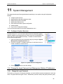
System Management.............................93
11.1
Configure System Services................................................................................93
11.2
Change the Login Password and Management Station IP Addresses ............93
11.2.1
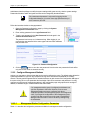
Change the Login Password....................................................................93
11.2.2
Configure Management Stations.............................................................94
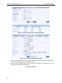
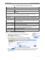
11.2.2.1 Management Station Configuration Parameters.....................................94
11.2.2.2 Add a Management Station Group..........................................................95
viii
11.2.2.3 Modify a Management Station Group .....................................................96
11.2.2.4 Delete a Management Station Group......................................................96
11.3
Configure System Identity ..................................................................................96
11.4
Setup Date and Time .........................................................................................96
11.4.1
Date/Time Configuration Parameters......................................................97
11.4.2
Maintain Date and Time...........................................................................97
11.4.3
View the System Date and Time .............................................................98
11.5
SNMP Setup.......................................................................................................98
11.5.1
SNMP Configuration Parameters ............................................................98
11.5.2
Configuring SNMP ...................................................................................99
11.6
System Configuration Management ..................................................................99
11.6.1
Reset to Factory Settings.........................................................................99
11.6.1.1 Reset to Factory Settings Using Configuration Manager .......................99
11.6.1.2 Reset to Factory Settings Using Reset Button......................................100
A
B
C
11.6.2
Backup System Configuration ...............................................................100
11.6.3
Restore System Configuration...............................................................100
11.7
Upgrade Firmware............................................................................................101
11.8
Reset the RX3041H .........................................................................................102
11.9
Logout Configuration Manager ........................................................................102
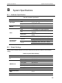
ALG Configuration ...............................105
System Specifications..........................109
B.1
Hardware Specification ....................................................................................109
B.2
Default Settings ................................................................................................109
IP Addresses, Network Masks, and
Subnets ................................................113
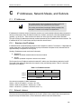
C.1
IP Addresses ....................................................................................................113
C.1.1
D
Structure of an IP address .....................................................................113
C.2
Network classes................................................................................................113
C.3
Subnet masks...................................................................................................114
Troubleshooting ...................................117
ix
D.1
E
F
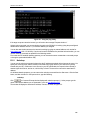
Diagnosing Problem using IP Utilities..............................................................118
D.1.1
Ping.........................................................................................................118
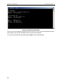
D.1.2
Nslookup.................................................................................................119
Glossary ...............................................121
Index ....................................................127
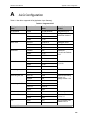
List of Figures
Figure 2.1. Front Panel LEDs...................................................................................................................................3
Figure 2.2. Rear Panel Connections........................................................................................................................4
Figure 3.1. Overview of Hardware Connections .................................................................................................. 10
Figure 3.2. Login Screen ....................................................................................................................................... 14
Figure 3.3. Setup Wizard Home Page.................................................................................................................. 15
Figure 3.4. Setup Wizard – Password Configuration Page ................................................................................. 15
Figure 3.5. Setup Wizard – System Identity Configuration Page ........................................................................ 16
Figure 3.6. Setup Wizard – Date/Time Configuration Page................................................................................. 16
Figure 3.7. Setup Wizard – LAN IP Configuration Page...................................................................................... 17
Figure 3.8. Setup Wizard – LAN DHCP Server Configuration Page................................................................... 17
Figure 3.9. Setup Wizard – WAN PPPoE Configuration Page............................................................................ 18
Figure 3.10. Setup Wizard – WAN Dynamic IP Configuration Page................................................................... 18
Figure 3.11. Setup Wizard – WAN Static IP Configuration Page ........................................................................ 19
Figure 4.1. Configuration Manager Login Screen ................................................................................................ 21
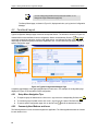
Figure 4.2. Typical Configuration Manager Page................................................................................................. 22
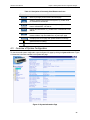
Figure 4.3. System Information Page ................................................................................................................... 23
Figure 5.1. LAN IP Address Configuration ........................................................................................................... 26
Figure 5.2. DHCP Configuration ........................................................................................................................... 28
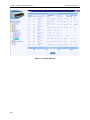
Figure 5.3. Sample DHCP Lease Table ............................................................................................................... 28
Figure 5.4. Fixed DHCP Lease Configuration Page ............................................................................................ 29
Figure 5.5. LAN Statistics Page ............................................................................................................................ 31
Figure 6.1. WAN PPPoE Configuration Page ...................................................................................................... 35
Figure 6.2. WAN PPPoE Configuration Summary............................................................................................... 35
Figure 6.3. WAN Dynamic IP (DHCP client) Configuration ................................................................................. 36
Figure 6.4. WAN Dynamic IP (DHCP client) Configuration Summary ................................................................ 37
Figure 6.5. WAN Static IP Configuration .............................................................................................................. 38
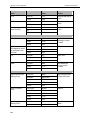
x
Figure 6.6. WAN Static IP Configuration .............................................................................................................. 38
Figure 6.7. WAN Statistics Page........................................................................................................................... 39
Figure 7.1. RIP Configuration............................................................................................................................... 42
Figure 7.2. Static Route Configuration................................................................................................................. 43
Figure 7.3. Routing Table..................................................................................................................................... 44
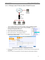
Figure 8.1. Network Diagram for RFC-2136 DDNS............................................................................................. 45
Figure 8.2. Network Diagram for HTTP DDNS .................................................................................................... 46
Figure 8.3. RFC-2136 DDNS Configuration......................................................................................................... 47
Figure 8.4. HTTP DDNS Configuration ................................................................................................................ 48
Figure 8.5. Host Table Configuration.................................................................................................................... 49
Figure 8.6. Host Table........................................................................................................................................... 49
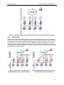
Figure 9.1 Static NAT – Mapping Four Private IP Addresses to Four Globally Valid IP Addresses .................. 53
Figure 9.2 Dynamic NAT – Four Private IP addresses Mapped to Three Valid IP Addresses .......................... 53
Figure 9.3 Dynamic NAT – PC-A can get an NAT association after PC-B is disconnected............................... 53
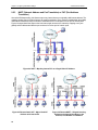
Figure 9.4 NAPT – Map Any Internal PCs to a Single Global IP Address .......................................................... 54
Figure 9.5 Reverse Static NAT – Map a Global IP Address to An Internal PC................................................... 54
Figure 9.6 Reverse NAPT – Relayed Incoming Packets to the Internal Host Base on the Protocol, Port
Number or IP Address ................................................................................................................................... 54
Figure 9.7. Inbound ACL configuration Example ................................................................................................. 58
Figure 9.8. Inbound ACL List ................................................................................................................................ 58
Figure 9.9. Outbound ACL Configuration Example.............................................................................................. 60
Figure 9.10. Outbound ACL List ........................................................................................................................... 60
Figure 9.11. URL Filter Configuration Example.................................................................................................... 62
Figure 9.12. URL Filter List ................................................................................................................................... 62
Figure 9.13. Self Access Rule Configuration Example ........................................................................................ 63
Figure 9.14. Service List Configuration................................................................................................................. 65
Figure 9.15. Service List........................................................................................................................................ 65
Figure 9.16. DoS Attack Protection List................................................................................................................ 68
Figure 9.17. DoS Configuration Page................................................................................................................... 68
Figure 9.18 Network Diagram for FTP Filter Example – Blocking FTP Delete Command................................. 71
Figure 9.19. FTP Filter Example – Configuring FTP Filter Rule .......................................................................... 71
Figure 9.20 FTP Filter Example – Firewall Configuration Assistant .................................................................... 72
Figure 9.21 FTP Filter Example – Add an FTP Filter to Deny FTP Delete Command....................................... 72
Figure 9.22. FTP Filter Example – Associate FTP Filter Rule to an ACL Rule................................................... 72
Figure 9.23. HTTP Filter Example – Configuring HTTP Filter Rule..................................................................... 73
Figure 9.24. HTTP Filter Example – Associate HTTP Filter Rule to an ACL Rule ............................................. 74
Figure 9.25. Modify an Application Filter............................................................................................................... 74
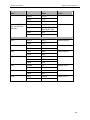
xi
Figure 9.26 IP Pool Configuration......................................................................................................................... 76
Figure 9.27. Network Diagram for IP Pool Configuration..................................................................................... 77
Figure 9.28. IP Pool Example – Add Two IP Pools – MISgroup1 and MISgroup2............................................. 77
Figure 9.29. IP Pool Example – Deny QUAKE-II Connection for MISgroup1..................................................... 78
Figure 9.30. NAT Pool configuration..................................................................................................................... 79
Figure 9.31. Network Diagram for NAT Pool Example ........................................................................................ 80
Figure 9.32. NAT Pool Example – Create a Static NAT Pool.............................................................................. 80
Figure 9.33. NAT Pool Example – Associate a NAT Pool to an ACL Rule......................................................... 81
Figure 9.34. Time Range Configuration ............................................................................................................... 82
Figure 9.35. Time Range Example – Create a Time Range ............................................................................... 83
Figure 9.36. Time Range Example – Deny FTP Access for MISgroup1 During OfficeHours............................ 83
Figure 9.37. Firewall Statistics .............................................................................................................................. 84
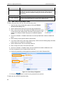
Figure 10.1. User Group Configuration................................................................................................................. 86
Figure 10.2. User Group and Users Configuration Example ............................................................................... 88
Figure 10.3. Group ACL Configuration Example.................................................................................................. 89
Figure 10.4. Group ACL List ................................................................................................................................. 89
Figure 10.5. Login Console ................................................................................................................................... 90
Figure 10.6. Login Status Screen ......................................................................................................................... 90
Figure 10.7. Network Diagram for Inbound Remote Access ............................................................................... 91
Figure 10.8. User and User Group Configuration Example................................................................................. 92
Figure 10.9. Group ACL Configuration Example.................................................................................................. 92
Figure 11.1. System Services Configuration ........................................................................................................ 93
Figure 11.2. Password Configuration ................................................................................................................... 94
Figure 11.3. Management Station Configuration ................................................................................................. 95
Figure 11.4. Management Station Summary ....................................................................................................... 96
Figure 11.5. System Identiy Configuration ........................................................................................................... 96
Figure 11.6. Date and Time Configuration Page.................................................................................................. 98
Figure 11.7. SNMP Configuration......................................................................................................................... 99
Figure 11.8. Existing SNMP Configuration........................................................................................................... 99
Figure 11.9. Default Setting Configuration............................................................................................................ 99
Figure 11.10. Counter Timer for Default Setting Configuration ......................................................................... 100
Figure 11.11. Backup System Configuration...................................................................................................... 100
Figure 11.12. Restore System Configuration ..................................................................................................... 101
Figure 11.13. Windows File Browser.................................................................................................................. 101
Figure 11.14. Firmware Upgrade Page .............................................................................................................. 102
Figure 11.15. Counter Down Counter for Firmware Update.............................................................................. 102
Figure 11.16. Router Reset Page ....................................................................................................................... 102
xii
Figure 11.17. Counter Down Counter for Router Reset .................................................................................... 102
Figure 11.18. Logout Page.................................................................................................................................. 103
Figure 11.19. Confirmation for Closing Browser (IE) ......................................................................................... 103
Figure D.1. Using the ping Utility......................................................................................................................... 119
Figure D.2. Using the nslookup Utility................................................................................................................. 120
List of Tables
Table 2.1. Front Panel Label and LEDs ..................................................................................................................3
Table 2.2. Rear Panel Labels and LEDs .................................................................................................................4
Table 2.3. DoS Attacks.............................................................................................................................................6
Table 3.1. LED Indicators...................................................................................................................................... 10
Table 3.2. Default Settings Summary................................................................................................................... 20
Table 4.1. Description of Commonly Used Buttons and Icons ............................................................................ 23
Table 5.1. LAN IP Configuration Parameters ....................................................................................................... 25
Table 5.2. DHCP Server Configuration Parameters ............................................................................................ 27
Table 5.3. DHCP Address Assignment Parameters ............................................................................................ 28
Table 5.4. Fixed DHCP Lease Configuration Parameters................................................................................... 29
Table 6.1. WAN PPPoE Configuration Parameters............................................................................................. 33
Table 6.2. WAN Dynamic IP Configuration Parameters...................................................................................... 36
Table 6.3. WAN Static IP Configuration Parameters ........................................................................................... 37
Table 7.1. Dynamic Routing (RIP) Configuration Parameters............................................................................. 41
Table 7.2. Static Route Configuration Parameters............................................................................................... 43
Table 8.1. DDNS Configuration Parameters ........................................................................................................ 46
Table 9.1. ACL Rule Configuration Parameters................................................................................................... 55
Table 9.2. URL Filter Configuration Parameters .................................................................................................. 61
Table 9.3. Self Access Configuration Parameters ............................................................................................... 63
Table 9.4. Service List configuration parameters ................................................................................................. 64
Table 9.5. DoS Protection Configuration Parameters.......................................................................................... 66
Table 9.6. Application Filter Configuration Parameters........................................................................................ 69
Table 9.7. IP Pool Configuration Parameters....................................................................................................... 75
Table 9.8. NAT Pool Configuration Parameters................................................................................................... 78
Table 9.9. Time Range Configuration Parameters............................................................................................... 81
Table 10.1. User Group Configuration Parameters.............................................................................................. 85
Table 10.2. Group ACL Specific Configuration Parameters ................................................................................ 88
Table 11.1. Management Station Configuration Parameters .............................................................................. 95
Table 11.2. Date/Time Configuration Parameters................................................................................................ 97
xiii
Table 11.3. Fixed DHCP Lease Configuration Parameters................................................................................. 98
Table A.1. Supported ALG .................................................................................................................................. 105
Table B.1. Hardware Specification...................................................................................................................... 109
Table B.2. System Default Settings .................................................................................................................... 109
Table C.1. IP Address structure.......................................................................................................................... 113
xiv
RX3041H User’s Manual
1
Chapter 1. Introduction
Introduction
Congratulations on becoming the owner of the high-speed router, RX3041H. Your LAN (local area network)
will now be able to access the Internet using your broadband connection such as those with ADSL or cable
modem.
This User Manual will show you how to set up your router, and how to customize its configuration to get the
most out of this product.
1.1
Features
10/100Base-T router providing Internet connectivity for all computers on your LAN
4-port 10/100Base-T (auto MDI/MDIX, auto speed negotiation) Ethernet switch
High performance firewall, and NAT (Network Address Translation) to provide secure Internet access
for your LAN
Automatic network address assignment through DHCP Server
Services including IP route, DNS and DDNS configuration, RIP, and IP performance monitoring
Configuration program accessible via a web browser, such as Microsoft Internet Explorer 5.5,
Netscape 7.0.2 or newer.
1.2
System Requirements
In order to use the RX3041H for Internet access, you must have the following:
ADSL or cable modem and the corresponding service up and running, with at least one public Internet
address assigned to your WAN
One or more computers each containing an Ethernet 10Base-T/100Base-T network interface card
(NIC)
(Optional) An Ethernet hub/switch, if you are connecting the device to more than four computers on an
Ethernet network.
For system configuration using the supplied web-based program: a web browser such as Internet
Explorer v5.5 or newer.
1.3
1.3.1
Using this Document
Notational conventions
Acronyms are defined the first time they appear in text and in the glossary (Appendix E).
For brevity, the RX3041H is sometimes referred to as “the router” or “your router”.
The terms LAN and network are used interchangeably to refer to a group of Ethernet-connected
computers at one site.
Sequence of mouse actions is denoted by the “Δ character. For instance, System Î System Info
means click the System menu and then click the System Info submenu.
1.3.2
Typographical conventions
Italics is used to identify terms that are defined in the glossary (Appendix E).
Boldface type text is used for items you select from menus and drop-down lists, and text strings you
type when prompted by the program.
Chapter 1. Introduction
1.3.3
RX3041H User’s Manual
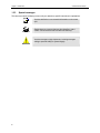
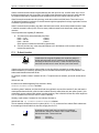
Special messages
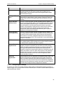
This document uses the following icons to call your attention to specific instructions or explanations.
Note
Definition
Provides clarification or non-essential information on the current
topic.
Explains terms or acronyms that may be unfamiliar to many
readers. These terms are also included in the Glossary.
Provides messages of high importance, including messages
relating to personal safety or system integrity.
WARNING
2
RX3041H User’s Manual
2
2.1
Chapter 2. Getting to Know the RX3041H
Getting to Know the RX3041H
Parts List
In addition to this document, your router should come with the following:
RX3041H High Speed Router
AC adapter
Ethernet cable (“straight-through” type)
2.2
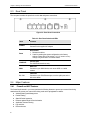
Front Panel
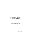
The front panel contains LED indicators that show the status of the unit.
Figure 2.1. Front Panel LEDs
Table 2.1. Front Panel Label and LEDs
LED
Label
Color
POWER
Green
ALARM
WAN
LAN1 –
LAN4
Green
Green
Green
Status
Indication
On
Unit is powered on
Off
Unit is powered off
On
System malfunctioned if this LED stays on. Note that the
LED is lit during system booting and is turned off
afterwards. This LED is also used along w/ reset button
during system configuration reset. Please refer to the
section 11.6.1.2 “Reset to Factory Settings Using Reset
Button” for further details.
Off
System functions normally.
On
WAN link established and active
Flashing
Data is transmitted or received via WAN connection
Off
No WAN link
On
LAN link is established
Flashing
Data is transmitted or received via LAN connection
Off
No LAN link
3
Chapter 2. Getting to Know the RX3041H
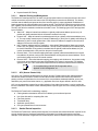
2.3
RX3041H User’s Manual
Rear Panel
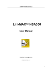
The rear panel contains the ports for the unit's data and power connections.
Figure 2.2. Rear Panel Connections
Table 2.2. Rear Panel Labels and LEDs
2.4
2.4.1
Label
Function
POWER
Power Input Jack
Connects to the supplied AC adapter
Reset
Reset Button
1. Reboots the device
2. Used for resetting the system configuration to the factory
settings. Please refer to the section 11.6.1.2 “Reset to Factory
Settings Using Reset Button” for further details.
CONSOLE
Console Port
For ASUSTeK internal use only.
WAN
WAN Port
Connects to your WAN device, such as an ADSL or a cable
modem.
P1 – P4
LAN Ports
Connects to your PC's Ethernet port, or to the uplink port on the
hub or the switch
Major Features
Firewall and NAT Features
The firewall implemented in your router provides the following features to protect your network from being
attacked and to prevent your network from being used as the springboard for attacks.
Address Sharing and Management
Packet Filtering
Stateful Packet Inspection
Defense against Denial of Service Attacks
Application Content Filtering
Log and Alert
Remote Access
4
RX3041H User’s Manual
Chapter 2 Getting to Know the RX3041H
Keyword based URL Filtering
2.4.1.1
Address Sharing and Management
The RX3041H Firewall provides NAT to share a single high-speed Internet connection and to save the cost of
multiple connections required for the hosts on the LAN segments connected to the RX3041H. This feature
conceals network address and prevents them from becoming public. It maps unregistered IP addresses of
hosts connected to the LAN with valid ones for Internet access. The RX3041H Firewall also provides reverse
NAT capability, which enables SOHO users to host various services such as e-mail servers, web servers, etc.
The NAT rules drive the translation mechanism at the NAT router. The following types of NAT are supported
by the RX3041H.
Static NAT – Maps an internal host address to a globally valid Internet address (one-to-one). All
packets are directly translated with the information contained in the map.
Dynamic NAT – Maps an internal host address dynamically to a globally valid Internet address (m-ton). The map usually contains a pool of internal IP addresses (m) and a pool of globally valid Internet IP
addresses (n) with m usually greater than n. Each internal IP address is mapped to one external IP
address on a first come first serve basis.
NAPT (Network Address and Port Translation) – Also called IP Masquerading. Maps many internal
hosts to only one globally valid Internet address. The map usually contains a pool of network ports to
be used for translation. Every packet is translated with the globally valid Internet address; the port
number is translated with a free pool from the pool of network ports.
Reverse Static – This is inbound mapping that maps a globally valid Internet address to an internal
host address. All packets coming to that external address are relayed to the internal address. This is
useful when hosting services in an internal machine.
Reverse NAPT – Also called inbound mapping, port mapping, and virtual server. Any packet coming
to the router can be relayed to the internal host based on the protocol, port number or IP Address
specified in the rule. This is useful when multiple services are hosted on different internal machines.
Note
2.4.1.2
For a complete listing of all NAT ALGs supported, refer to
Appendix A “ALG Configuration” on.
ACL (Access Control List)
ACL rule is one of the basic building blocks for network security. Firewall monitors each individual packet,
decodes the header information of inbound and outbound traffic and then either blocks the packet from
passing or allows it to pass based on the contents of the source address, destination address, source port,
destination port, protocol and other criterion, e.g. application filter, time ranges, defined in the ACL rules.
ACL is a very appropriate measure for providing isolation of one subnet from another. It can be used as the
first line of defense in the network to block inbound packets of specific types from ever reaching the protected
network.
The RX3041H Firewall’s ACL methodology supports:
Filtering based on destination and source IP address, port number and protocol
Use of the wild card for composing filter rules
Filter Rule priorities
Time based filters
Application specific filters
User group based filters for remote access
2.4.1.3
Stateful Packet Inspection
The RX3041H Firewall uses “stateful packet inspection” that extracts state-related information required for the
security decision from the packet and maintains this information for evaluating subsequent connection
attempts. It has awareness of application and creates dynamic sessions that allow dynamic connections so
5
Chapter 2. Getting to Know the RX3041H
RX3041H User’s Manual
that no ports need to be opened other than the required ones. This provides a solution which is highly secure
and that offers scalability and extensibility.
2.4.1.4
Defense against DoS Attacks
The RX3041H Firewall has an Attack Defense Engine that protects internal networks from known types of
Internet attacks. It provides automatic protection from Denial of Service (DoS) attacks such as SYN flooding,
IP smurfing, LAND, Ping of Death and all re-assembly attacks. It can drop ICMP redirects and IP loose/strict
source routing packets. For example, the RX3041H Firewall provides protection from “WinNuke”, a widely
used program to remotely crash unprotected Windows systems in the Internet. The RX3041H Firewall also
provides protection from a variety of common Internet attacks such as IP Spoofing, Ping of Death, Land Attack,
Reassembly and SYN flooding.
The type of attack protections provided by the RX3041H are listed in Table 2.3.
Table 2.3. DoS Attacks
2.4.1.5
Type of Attack
Name of Attacks
Re-assembly attacks
Bonk, Boink, Teardrop (New Tear),
Overdrop, Opentear, Syndrop, Jolt
ICMP Attacks
Ping of Death, Smurf, Twinge
Flooders
ICMP Flooder, UDP Flooder, SYN
Flooder
Port Scans
TCP XMAS Scan, TCP Null Scan
TCP SYN Scan, TCP Stealth Scan
TCP Attacks
TCP sequence number prediction, TCP
out-of sequence attacks
Protection with PF Rules
Echo-Chargen, Ascend Kill
Miscellaneous Attacks
IP Spoofing, LAND, Targa, Tentacle
MIME Flood, Winnuke, FTP Bounce, IP
unaligned time stamp attack
Application Command Filtering
The RX3041H Firewall allows network administrators to block, monitor, and report on network users access to
non-business and objectionable content. This high-performance content access control results in increased
productivity, lower bandwidth usage and reduced legal liability.
The RX3041H Firewall has the ability to handle active content filtering on certain application protocols such as
HTTP, FTP, SMTP and RPC.
HTTP – You can define HTTP extension based filtering schemes for blocking
ActiveX
Java Archive
Java Applets
Microsoft Archives
URLs based on file extensions.
FTP – allows you to define and enforce the file transfer policy for the site or group of users
SMTP – allows you to filter operations such as VRFY, EXPN, etc. which reveal excess information
about the recipient.
RPC – allows you to filter programs based on the assigned RPC program numbers.
6
RX3041H User’s Manual
2.4.1.6
Chapter 2 Getting to Know the RX3041H
Application Level Gateway (ALG)
Applications such as FTP, games etc., open connections dynamically based on the respective application
parameter. To go through the firewall on the RX3041H, packets pertaining to an application, require a
corresponding allow rule. In the absence of such rules, the packets will be dropped by the RX3041H Firewall.
As it is not feasible to create policies for numerous applications dynamically (at the same time without
compromising security), intelligence in the form of Application Level Gateways (ALG), is built to parse packets
for applications and open dynamic associations. The RX3041H Firewall provides a number of ALGs for
popular applications such as FTP, H.323, RTSP, Microsoft Games, SIP, etc.
2.4.1.7
URL Filtering
A set of keywords that should not appear in the URL (Uniform Resource Locator, e.g. www.yahoo.com) can be
defined. Any URL containing one or more of these keywords will be blocked. This is a policy independent
feature i.e. it cannot be associated to ACL rules. This feature can be independently enabled or disabled, but
works only if firewall is enabled.
2.4.1.8
Log and Alerts
Events in the network, that could be attempts to affect its security, are recorded in the RX3041H System log
file. Event details are recorded in WELF (WebTrends Enhanced Log Format ) format so that statistical tools
can be used to generate custom reports. The RX3041H Firewall can also forward Syslog information to a
Syslog server on a private network.
The RX3041H Firewall supports:
Alerts sent to the administrator via e-mail.
Maintains at a minimum, log details such as, time of packet arrival, description of action taken by
Firewall and reason for action.
Supports the UNIX Syslog format.
Sends log report e-mails as scheduled by the network administrator or by default when the log file is
full.
All the messages are sent in the WELF format.
ICMP logging to show code and type.
2.4.1.9
Remote Access
The RX3041H Firewall allows the network administrator to segregate the user community into Access Policies
per group. A user can log in using the login page (Refer to “User Login Process” on page 67). After a user is
authenticated successfully, the RX3041H Firewall dynamically activates the user-group’s set of access policies.
These policies will subsequently be enforced until the user logs out of the session or until inactivity timeout
period has lapsed.
7
RX3041H User’s Manual
3
Chapter 3. Quick Start Guide
Quick Start Guide
This Quick Start Guide provides basic instructions for connecting your router to a computer or a LAN and to
the Internet.
Part 1 provides instructions to set up the hardware.
Part 2 describes how to configure Internet properties on your computer(s).
Part 3 shows you how to configure basic settings on the RX3041H to get your LAN connected to the
Internet.
After setting up and configuring your router, you can follow the instructions on page 20 to verify that it is
working properly.
This Quick Start Guide assumes that you have already established ADSL or cable modem service with your
Internet service provider (ISP). These instructions provide a basic configuration that should be compatible with
your home or small office network setup. Refer to the subsequent chapters for additional configuration
instructions.
3.1
Part 1 — Connecting the Hardware
In Part 1, you connect the device to an ADSL or a cable modem (which in turn is connected to a phone jack or
a cable outlet), the power outlet, and your computer or network.
WARNING
Before you begin, turn the power off for all devices. These
include your computer(s), your LAN hub/switch (if applicable),
and the router.
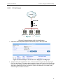
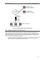
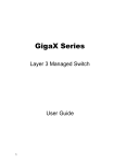
Figure 3.1 illustrates the hardware connections. Please follow the steps that follow for specific instructions.
3.1.1
Step 1. Connect an ADSL or a cable modem.
For the RX3041H: Connect one end of the Ethernet cable to the port labeled WAN on the rear panel of the
device. Connect the other end to the Ethernet port on the ADSL or cable modem.
3.1.2
Step 2. Connect computers or a LAN.
If your LAN has no more than 4 computers, you can use an Ethernet cable to connect computers directly to
the built-in switch on the device. Note that you should attach one end of the Ethernet cable to any of the port
labeled LAN1 – LAN4 on the rear panel of the device and connect the other end to the Ethernet port of a
computer.
If your LAN has more than 4 computers, you can attach one end of an Ethernet cable to a hub or a switch
(probably an uplink port; please refer to the hub or switch documentations for instructions) and the other to the
Ethernet switch port (labeled LAN1 – LAN4) on the RX3041H.
Note that either the crossover or straight-through Ethernet cable can be used to connect the built-in switch and
computers, hubs or switches as the built-in switch is smart enough to make connections with either type of
cables.
3.1.3
Step 3. Attach the AC adapter.
Connect the AC adapter to the POWER input jack on the rear panel of your router and plug the adapter to a
power outlet or a power strip.
9
Chapter 3. Quick Start Guide
3.1.4
RX3041H User’s Manual
Step 4 – Power up devices.
Turn on the RX3041H, the ADSL or cable modem and power up your computers.
Press the Power switch on the rear panel of the RX3041H to the ON position. Turn on your ADSL or cable
modem. Turn on and boot up your computer(s) and any LAN devices such as hubs or switches.
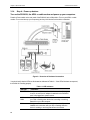
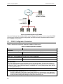
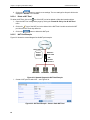
Figure 3.1. Overview of Hardware Connections
You should verify that the LEDs are illuminated as indicated in Table 3.1. If the LEDs illuminate as expected,
the RX3041H is working properly.
Table 3.1. LED Indicators
10
This LED:
...should be:
POWER
Solid green to indicate that the device is turned on. If this light
is not on, check if the AC adapter is attached to the RX3041H
and if it is plugged into a power source.
LAN1 –
LAN4
Solid green to indicate that the device can communicate with
your LAN or flashing when the device is sending or receiving
data to/from your LAN computer.
WAN
Solid green to indicate that the device has successfully
established a connection with your ISP or flashing when the
device is sending or receiving data to/from the Internet.
RX3041H User’s Manual
3.2
Chapter 3. Quick Start Guide
Part 2 — Configuring Your Computers
Part 2 of the Quick Start Guide provides instructions for configuring the Internet settings on your computers to
work with the RX3041H.
3.2.1
Before you begin
By default, the RX3041H automatically assigns all required Internet settings to your PCs. You need only to
configure the PCs to accept the information when it is assigned.
Note
In some cases, you may want to configure network settings
manually to some or all of your computers rather than allow the
RX3041H to do so. See “Assigning static IP addresses to your PCs”
in page 13 for instructions.
If you have connected your PC via Ethernet to the RX3041H, follow the instructions that correspond to
the operating system installed on your PC.
3.2.2
Windows[CT6]® XP PCs:
1. In the Windows task bar, click the <Start> button, and then click Control Panel.
2. Double-click the Network Connections icon.
3. In the LAN or High-Speed Internet window, right-click on icon corresponding to your network
interface card (NIC) and select Properties. (Often this icon is labeled Local Area Connection).
The Local Area Connection dialog box displays with a list of currently installed network items.
4. Ensure that the check box to the left of the item labeled Internet Protocol TCP/IP is checked, and
click <Properties> button.
5. In the Internet Protocol (TCP/IP) Properties dialog box, click the radio button labeled Obtain an
IP address automatically. Also click the radio button labeled Obtain DNS server address
automatically.
6. Click <OK> button twice to confirm your changes, and close the Control Panel.
3.2.3
Windows® 2000 PCs:
First, check for the IP protocol and, if necessary, install it:
1. In the Windows task bar, click the <Start> button, point to Settings, and then click Control Panel.
2. Double-click the Network and Dial-up Connections icon.
3. In the Network and Dial-up Connections window, right-click the Local Area Connection icon,
and then select Properties.
The Local Area Connection Properties dialog box displays a list of currently installed network
components. If the list includes Internet Protocol (TCP/IP), then the protocol has already been
enabled. Skip to step 10.
4. If Internet Protocol (TCP/IP) does not display as an installed component, click <Install> button.
5. In the Select Network Component Type dialog box, select Protocol, and then click <Add> button.
6. Select Internet Protocol (TCP/IP) in the Network Protocols list, and then click <OK> button.
You may be prompted to install files from your Windows 2000 installation CD or other media. Follow
the instructions to install the files.
11
Chapter 3. Quick Start Guide
RX3041H User’s Manual
7. If prompted, click <OK> button to restart your computer with the new settings.
Next, configure the PCs to accept IP addresses assigned by the RX3041H:
8. In the Control Panel, double-click the Network and Dial-up Connections icon.
9. In Network and Dial-up Connections window, right-click the Local Area Connection icon, and
then select Properties.
10. In the Local Area Connection Properties dialog box, select Internet Protocol (TCP/IP), and then
click <Properties> button.
11. In the Internet Protocol (TCP/IP) Properties dialog box, click the radio button labeled Obtain an
IP address automatically. Also click the radio button labeled Obtain DNS server address
automatically.
12. Click <OK> button twice to confirm and save your changes, and then close the Control Panel.
3.2.4
Windows® 95, 98, and Me PCs
1. In the Windows task bar, click the <Start> button, point to Settings, and then click Control Panel.
2. Double-click the Network icon.
In the Network dialog box, look for an entry started w/ “TCP/IP ->” and the name of your network
adapter, and then click <Properties> button. You may have to scroll down the list to find this entry.
If the list includes such an entry, then the TCP/IP protocol has already been enabled. Skip to step 8.
3. If Internet Protocol (TCP/IP) does not display as an installed component, click <Add> button.
4. In the Select Network Component Type dialog box, select Protocol, and then click <Add> button.
5. Select Microsoft in the Manufacturers list box, and then click TCP/IP in the Network Protocols list,
box and then click <OK> button.
You may be prompted to install files from your Windows 95, 98 or Me installation CD or other media.
Follow the instructions to install the files.
6. If prompted, click <OK> button to restart your computer with the new settings.
Next, configure the PCs to accept IP information assigned by the RX3041H:
7. In the Control Panel, double-click the Network icon.
8. In the Network dialog box, select an entry started with “TCP/IP ->” and the name of your network
adapter, and then click <Properties> button.
9. In the TCP/IP Properties dialog box, click the radio button labeled Obtain an IP address
automatically.
10. In the TCP/IP Properties dialog box, click the “Default Gateway” tab. Enter 192.168.1.1 (the
default LAN port IP address of the RX3041H) in the “New gateway” address field and click
<Add> button to add the default gateway entry.
11. Click <OK> button twice to confirm and save your changes, and then close the Control Panel.
12. If prompted to restart your computer, click <OK> button to do so with the new settings.
3.2.5
Windows® NT 4.0 workstations:
First, check for the IP protocol and, if necessary, install it:
1. In the Windows NT task bar, click the <Start> button, point to Settings, and then click Control
Panel.
12
RX3041H User’s Manual
Chapter 3. Quick Start Guide
2. In the Control Panel window, double click the Network icon.
3. In the Network dialog box, click the Protocols tab.
The Protocols tab displays a list of currently installed network protocols. If the list includes TCP/IP
Protocol, then the protocol has already been enabled. Skip to step 9.
4. If TCP/IP does not display as an installed component, click <Add> button.
5. In the Select Network Protocol dialog box, select TCP/IP, and then click <OK> button.
You may be prompted to install files from your Windows NT installation CD or other media. Follow
the instructions to install the files.
After all files are installed, a window displays to inform you that a TCP/IP service called DHCP can
be set up to dynamically assign IP information.
6. Click <Yes> button to continue, and then click <OK> button if prompted to restart your computer.
Next, configure the PCs to accept IP addresses assigned by the RX3041H:
7. Open the Control Panel window, and then double-click the Network icon.
8. In the Network dialog box, click the Protocols tab.
9. In the Protocols tab, select TCP/IP, and then click <Properties> button.
10. In the Microsoft TCP/IP Properties dialog box, click the radio button labeled Obtain an IP
address from a DHCP server.
11. Click <OK> button twice to confirm and save your changes, and then close the Control Panel.
3.2.6
Assigning static IP addresses to your PCs
In some cases, you may want to assign IP addresses to some or all of your PCs directly (often called
“statically”), rather than allowing the RX3041H to assign them. This option may be desirable (but not required)
if:
You have obtained one or more public IP addresses that you want to always associate with specific
computers (for example, if you are using a computer as a public web server).
You maintain different subnets on your LAN.
However, during the first time configuration of your RX3041H, you must assign an IP address in the
192.168.1.0 network for your PC, say 192.168.1.2, in order to establish connection between the RX3041H and
your PC as the default LAN IP on RX3041H is pre-configured as 192.168.1.1. Enter 255.255.255.0 for the
subnet mask and 192.168.1.1 for the default gateway. These settings may be changed later to reflect your true
network environment.
On each PC to which you want to assign static information, follow the instructions on pages 11 through 12
relating only to checking for and/or installing the IP protocol. Once it is installed, continue to follow the
instructions for displaying each of the Internet Protocol (TCP/IP) properties. Instead of enabling dynamic
assignment of the IP addresses for the computer, DNS server, and default gateway, click the radio buttons that
enable you to enter the information manually.
Note
3.3
Your PCs must have IP addresses that place them in the same
subnet as the router’s LAN port. If you manually assign IP
addresses to all your LAN PCs, you can follow the instructions in
Chapter 5 to change the router’s LAN port IP address accordingly.
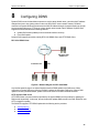
Part 3 — Quick Configuration of Your Router
In Part 3, you log into the Configuration Manager on the router and configure basic settings for your Internet
connection. Your ISP should provide you with the necessary information to complete this step. Note the intent
13
Chapter 3. Quick Start Guide
RX3041H User’s Manual
here is to quickly get the router up and running, instructions are concise. You may refer to corresponding
chapters for more details.
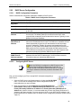
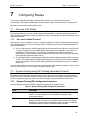
3.3.1
Buttons Used in Setup Wizard
The RX3041H provides a preinstalled software program called Configuration Manager that enables you to
configure the RX3041H via your Web browser. The settings that you are most likely to need to change before
using the device are grouped onto sequence of configuration pages guided by Setup Wizard. The following
table shows the buttons that you’ll encounter in Setup Wizard.
Button
Function
Click this button to save the information and proceed to the next
configuration page.
Click this button to go back to the previous configuration page.
3.3.2
Setting Up the RX3041H
Follow these instructions to setup the RX3041H:
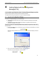
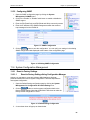
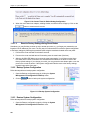
1. Before accessing the Configuration Manager in the RX3041H, make sure that the HTTP proxy
setting is disabled in your browser. In IE, click “Tools” Î “Internet Options…” Î
“Connections” tab Î “LAN settings…” and then uncheck “Use proxy server for your LAN …”
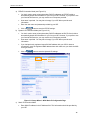
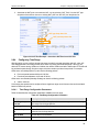
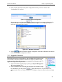
2. On any PC connected to one of the four LAN ports on the RX3041H, open your Web browser,
and type the following URL in the address/location box, and press <Enter>:
http://192.168.1.1
This is the predefined IP address for the LAN port on the RX3041H.
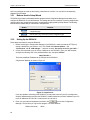
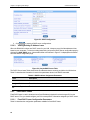
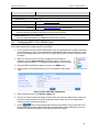
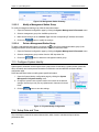
A login screen displays, as shown in Figure 3.2.
Figure 3.2. Login Screen
If you have problem connecting to the RX3041H, you may want to check if your PC is configured to
accept IP address assignment from the RX3041H. Another method is to set the IP address of your PC
to any IP address in the 192.168.1.0 network, such as 192.168.1.2.
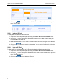
3. Enter your user name and password, and then click
to enter the Configuration
Manager. The first time you log into this program, use these defaults:
Default User Name:
14
admin
RX3041H User’s Manual
Chapter 3. Quick Start Guide
Default Password:
Note
admin
You can change the password at any time (see section 11.2
Change the Login Password on page 93).
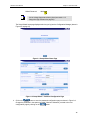
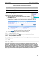
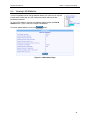
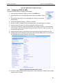
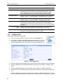
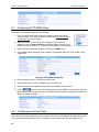
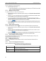
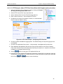
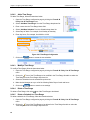
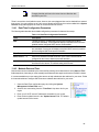
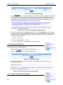
The Setup Wizard home page displays each time you log into the Configuration Manager (shown in
Figure 3.3 on page 15).
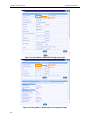
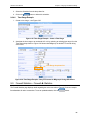
Figure 3.3. Setup Wizard Home Page
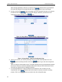
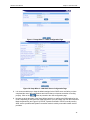
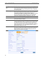
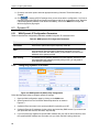
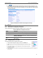
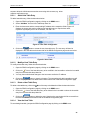
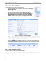
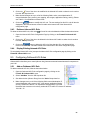
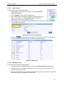
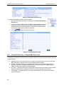
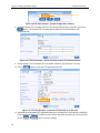
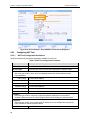
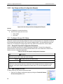
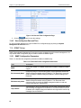
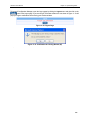
Figure 3.4. Setup Wizard – Password Configuration Page
button to enter the password configuration page as shown in Figure 3.4.
4. Click on the
Change the password in the spaces provided if desired. Otherwise, proceed to the next
configuration page by clicking on the
button.
15
Chapter 3. Quick Start Guide
RX3041H User’s Manual
When changing passwords, make sure you enter the existing login password in the Login Password
field, make any changes for the passwords and click the
button to save the changes.
5. Now we are at the System Information setup page; enter the requested information in the spaces
provided and click the
button to save the changes. Otherwise, proceed to the next
configuration page by clicking on the
button.
Figure 3.5. Setup Wizard – System Identity Configuration Page
Figure 3.6. Setup Wizard – Date/Time Configuration Page
6. Set the time zone for your router by selecting one from the Time Zone drop-down list. Click
to save the settings and then click on the
button to go to the next configuration
page.
There is no real time clock inside the router. The system date and time may be maintained by external
time servers. There is no need to set the date and time here unless you don’t have access to a time
server and you want the router to maintain its own time.
7. It is recommended that you keep the default LAN IP settings for now until after you have
completed the rest of the configurations and confirm that your Internet connection is working
properly. Click on the
16
button to proceed to the next configuration page.
RX3041H User’s Manual
Chapter 3. Quick Start Guide
Figure 3.7. Setup Wizard – LAN IP Configuration Page
Figure 3.8. Setup Wizard – LAN DHCP Server Configuration Page
8. It is recommended that you keep the default settings for the DHCP server until after you have
completed the rest of the configurations and confirm that your Internet connection is working
properly. Click on the
button to proceed to the next configuration page.
9. Now we are at the last page of the Setup Wizard, which is to configure the WAN settings for the
router. Depending on the connection mode required for your ISP, select one from the Connection
Mode drop-down list (see Figure 3.9): PPPoE, Dynamic and Static. PPPoE is usually used by
ADSL service providers and Dynamic connection mode is used by most cable modem service
providers.
17
Chapter 3. Quick Start Guide
RX3041H User’s Manual
Connection
Mode dropdown list
Figure 3.9. Setup Wizard – WAN PPPoE Configuration Page
Connection
Mode dropdown list
Figure 3.10. Setup Wizard – WAN Dynamic IP Configuration Page
18
RX3041H User’s Manual
Chapter 3. Quick Start Guide
a) PPPoE Connection Mode (see Figure 3.9)
•
You don’t need to enter primary/secondary DNS IP addresses as PPPoE is able to
automatically obtain this information for you from your ISP. However, if you prefer to use
your favorite DNS servers, you may enter them in the space provided.
•
Host name is optional. You may leave it empty if your ISP did not provide such
information.
•
Enter the user name and password provided by your ISP.
•
Click on
button to save the PPPoE settings.
b) Dynamic IP Connection Mode (see Figure 3.10)
•
You don’t need to enter primary/secondary DNS IP addresses as DHCP client is able to
automatically obtain this information for you from your ISP. However, if you prefer to use
your favorite DNS servers, you may enter them in the space provided.
•
Host name is optional. You may leave it empty if your ISP did not provide such
information.
•
If you had previously registered a specific MAC address with your ISP for Internet
connections, enter the registered MAC address here and make sure you check the MAC
cloning check box.
•
Click on
button to save the dynamic IP settings.
Connection
Mode dropdown list
Figure 3.11. Setup Wizard – WAN Static IP Configuration Page
c) Static IP Connection Mode
•
Enter WAN IP address in the IP Address field. This information should be provided by
your ISP.
19
Chapter 3. Quick Start Guide
RX3041H User’s Manual
•
Enter Subnet Mask for the WAN. This information should be provided by your ISP.
Typically, it is 255.255.255.0.
•
Enter gateway address provided by your ISP in the space provided.
•
Enter at lease the primary DNS IP address provided by your ISP. Secondary DNS IP
address is optional. Enter it in the space provided if you have such information from your
ISP.
•
Click
to save the static IP settings
You have now completed customizing basic configuration settings. Read the following section to determine if
you have access to the Internet.
3.3.3
Testing Your Setup
At this point, the RX3041H should enable any computer on your LAN to use the RX3041H’s ADSL or cable
modem connection to access the Internet.
To test the Internet connection, open your web browser, and type the URL of any external website (such as
http://www.asus.com). The LED labeled WAN should be blinking rapidly and may appear solid as the device
connects to the site. You should also be able to browse the web site through your web browser.
If the LEDs do not illuminate as expected or the web page does not display, see Appendix D for
troubleshooting suggestions.
3.3.4
Default Router Settings
In addition to handling the DSL connection to your ISP, the router provides a variety of services to your
network. The device is pre-configured with default settings for use with a typical home or small office network.
Table 3.2 lists some of the most important default settings; these and other features are described fully in the
subsequent chapters. For a complete list of default settings, please refer to the section B.2 “Default Settings”. If
you are familiar with network configuration settings, review the settings in Table 3.2 to verify that they meet the
needs of your network. Follow the instructions to change them if necessary. If you are unfamiliar with these
settings, try using the device without modification.
Before modifying any settings, review Chapter 4 for general information about accessing and using the
Configuration Manager.
Table 3.2. Default Settings Summary
Option
Default Setting
DHCP (Dynamic
Host
Configuration
Protocol)
DHCP server enabled with the
following pool of addresses:
LAN Port IP
Address
Static IP address: 192.168.1.1
20
192.168.1.10 through 192.168.1.200
subnet mask: 255.255.255.0
Explanation/Instructions
The router maintains a pool of private IP
addresses for dynamic assignment to your
LAN computers. To use this service, you
must have set up your computers to
accept IP information dynamically, as
described in Part 2 of the Quick Start
Guide. See section 5.2 for an explanation
of the DHCP service.
This is the IP address of the LAN port on
the RX3041H. The LAN port connects the
device to your Ethernet network. Typically,
you will not need to change this address.
See section 5.1 LAN IP Address for
instructions.
RX3041H User’s Manual
4
Chapter 4. Getting Started with the Configuration Manager
Getting Started with the Configuration
Manager[CT9]
Your router includes a preinstalled program called the Configuration Manager, which allows you to customize
the device settings to meet the needs of your network. You access the Configuration Manager through a web
browser from any PC that has access to the router via network connections.
This chapter describes the general guidelines for using the Configuration Manager.
4.1
Log into the Configuration Manager
To access the Configuration Manager, you need the following:
A computer that has access to the router via network connections as described in the Quick Start
Guide chapter.
A web browser on your computer. Configuration Manager is compatible with Microsoft Internet
Explorer® 5.5, Netscape 7.0.2 or newer.
Although you may log into the Configuration Manager from any computer that can reach your router via the
LAN or WAN connections, the instructions provided here assumes that your computer is connected to the LAN
port of your router.
1. From a LAN computer, open your web browser, type the following in the web address (or location)
box, and press <Enter>:
http://192.168.1.1
This is the predefined IP address for the LAN port of your router. A login screen displays, as shown in
Figure 4.1.
Figure 4.1. Configuration Manager Login Screen
2. Enter your user name and password, and then click
button.
The first time you log into the program, use these defaults:
Default User Name:
admin
Default Password:
admin
21
Chapter 4. Getting Started with the Configuration Manager
Note
RX3041H User’s Manual
You can change the password at any time (see section 11.2.1
Change the Login Password on page 93).
The Setup Wizard page, as shown in Figure 3.3, displays each time you log into the Configuration
Manager.
4.2
Functional Layout
Typical Configuration Manager page consists of two separate frames. The left frame, as shown in Figure 4.2,
contains all the menus available for device configuration. Menus are indicated by file icons, , and related
or ,
menus are grouped into categories, such as LAN, WAN and etc., and indicated by folder icons,
depending on whether the group of menus are expanded or not. You can click on any of these to display a
specific configuration page.
Setup Menu Frame
Configuration Frame
Figure 4.2. Typical Configuration Manager Page
A separate page displays in the right-hand-side frame for each menu. For example, the configuration page
displayed in Figure 4.2 is intended for DHCP configuration.
4.2.1
Setup Menu Navigation Tips
To expand a group of related menus: click on the + sign next to the corresponding file folder icon,
To contract a group of related menus: click on the – sign next to the “opened” file folder icon,
To open a specific configuration page, click on the file icons,
4.2.2
.
, next to the desired menu item.
Commonly Used Buttons and Icons
The following buttons or icons are used throughout the application. The following table describes the function
for each button or icon.
22
.
RX3041H User’s Manual
Chapter 4. Getting Started with the Configuration Manager
Table 4.1. Description of Commonly Used Buttons and Icons
Button/Icon
Function
Stores any changes you have made on the current page.
Adds the existing configuration to the system, e.g. a static route
or a firewall ACL rule and etc.
Modifies the existing configuration in the system, e.g. a static
route or a firewall ACL rule and etc.
Deletes the selected item, e.g. a static route or a firewall ACL rule
and etc.
Launches the online help for the current topic in a separate
browser window. Help is available from any main topic page.
Redisplays the current page with updated statistics or settings.
Selects the item for editing.
Deletes the selected item.
4.3
Overview of System Configuration
To view the overall system configuration, open the System Info page by clicking the System Info menu. Figure
4.3 shows the information available in the System Info page.
Figure 4.3. System Information Page
23
RX3041H User’s Manual
5
Chapter 5. Configuring LAN Settings
Configuring LAN Settings
This chapter describes how to configure LAN properties for the LAN interface on the RX3041H that
communicates with your LAN computers. You’ll learn to configure IP address, DHCP and DNS server for your
LAN in this chapter.
5.1
LAN IP Address
If you are using the RX3041H with multiple PCs on your LAN, you must connect the LAN via the Ethernet
ports on the built-in Ethernet switch. You must assign a unique IP address to each device residing on your
LAN. The LAN IP address identifies the RX3041H as a node on your network must be in the same subnet as
the PCs on your LAN. The default LAN IP for the RX3041H is 192.168.1.1.
Definition
A network node can be thought of as any interface where a
device connects to the network, such as the RX3041H’s LAN port
and the network interface cards on your PCs. See Appendix A for
an explanation of subnets.
You can change the default to reflect the true IP address that you want to use with your network.
Note
5.1.1
The RX3041H itself can function as a DHCP server for your LAN
computers, as described in section 5.2.2, but not for its own
LAN port.
LAN IP Configuration Parameters
Table 5.1describes the configuration parameters available for LAN IP configuration.
Table 5.1. LAN IP Configuration Parameters
Setting
Description
IP Address
The LAN IP address of the RX3041H. This IP is used by your computers to
identify the RX3041H’s LAN port. Note that the public IP address assigned to
you by your ISP is not your LAN IP address. The public IP address identifies
the WAN port on the RX3041H to the Internet.
Subnet Mask
The LAN subnet mask identifies which parts of the LAN IP Address refer to
your network as a whole and which parts refer specifically to nodes on the
network. Your device is preconfigured with a default subnet mask of
255.255.255.0.
5.1.2
Configuring the LAN IP Address
Follow these steps to change the default LAN IP address.
1. Open the LAN configuration page by clicking the LAN Î IP menu.
2. Enter a LAN IP address and subnet mask for the RX3041H in the IP
Address and Subnet Mask fields as shown in Figure 5.1.
25
Chapter 5. Configuring LAN Settings
RX3041H User’s Manual
Figure 5.1. LAN IP Address Configuration
button to save the LAN IP address.
3. Click.
If you change the LAN IP address, the connection will be terminated.
4. Reconfigure your PCs, if necessary, so that their IP addresses place them in the same subnet as
the new IP address of the LAN port. See the Quick Start Guide chapter, “Part 2 — Configuring
Your Computers,” for instructions.
5. Log into Configuration Manager by typing the new IP address in your Web browser’s
address/location box.
5.2
5.2.1
5.2.1.1
DHCP (Dynamic Host Configuration Protocol)
Introduction
What is DHCP?
DHCP is a protocol that enables network administrators to centrally manage the assignment and distribution of
IP information to computers on a network.
When you enable DHCP on a network, you allow a device — such as the RX3041H — to assign temporary IP
addresses to your computers whenever they connect to your network. The assigning device is called a DHCP
server, and the receiving device is a DHCP client.
Note
If you followed the Quick Start Guide instructions, you either
configured each LAN PC with an IP address, or you specified that
it will receive IP information dynamically (automatically). If you
chose to have the information assigned dynamically, then you
configured your PCs as DHCP clients that will accept IP
addresses assigned from a DCHP server such as the RX3041H.
The DHCP server draws from a defined pool of IP addresses and “leases” them for a specified amount of time
to your computers when they request an Internet session. It monitors, collects, and redistributes the addresses
as needed.
On a DHCP-enabled network, the IP information is assigned dynamically rather than statically. A DHCP client
can be assigned a different address from the pool each time it reconnects to the network.
5.2.1.2
Why use DHCP?
DHCP allows you to manage and distribute IP addresses throughout your network from the RX3041H. Without
DHCP, you would have to configure each computer separately with IP address and related information. DHCP
is commonly used with large networks and those that are frequently expanded or otherwise updated.
26
RX3041H User’s Manual
5.2.2
5.2.2.1
Chapter 5. Configuring LAN Settings
DHCP Server Configuration
DHCP Configuration Parameters
Table 5.2 describes the configuration parameters available for DHCP service.
Table 5.2. DHCP Server Configuration Parameters
Field
Description
IP Address Pool
Begin/End
Specify the lowest and highest addresses in the DHCP address pool.
Subnet Mask
Enter the subnet mask to be used for the DHCP address pool.
Lease Time
The amount of time the assigned address will be used by a device connected
on the LAN.
Default Gateway IP
Address
The address of the default gateway for computers that receive IP addresses
from this pool. The default gateway is the device that the DHCP client
computers first contacted to communicate with the Internet. Typically, it is the
RX3041H’s LAN port IP address.
Primary/Secondary
DNS Server IP
Address
The IP address of the Domain Name System server to be used by computers
that receive IP addresses from this pool. The DNS server translates common
Internet names that you type into your web browser into their equivalent
numeric IP addresses. Typically, the server(s) are located with your ISP.
However, you may enter LAN IP address of the RX3041H as it will serve as
DNS proxy for the LAN computers and forward the DNS request from the
LAN to DNS servers and relay the results back to the LAN computers. Note
that both the primary and secondary DNS servers are optional.
Primary/Secondary
WINS Server IP
Address (optional)
The IP address of the WINS servers to be used by computers that receive IP
addresses from the DHCP IP address pool. You don’t need to enter this
information unless your network has WINS servers.
5.2.2.2
Configuring DHCP Server
Note
By default, the RX3041H is configured as a DHCP server on the
LAN side, with a predefined IP address pool of 192.168.1.10
through 192.168.1.200 (subnet mask 255.255.255.0). To change
this range of addresses, follow the procedures described in this
section.
First, you must configure your PCs to accept DHCP information assigned by a
DHCP server:
1. Open the DHCP server configuration page by clicking the LAN Î DHCP
menu. You will see the existing DHCP server configuration and the IP
lease table when you open the page.
2. Enter the information for the IP Address Pool (Begin/End Address),
Subnet Mask, Lease Time and Default Gateway IP Address fields; others, such as
Primary/Secondary DNS Server IP Address and Primary/Secondary WINS Server IP
Address are optional. However, it is recommended that you enter the primary DNS server IP
address in the space provided. You may enter the LAN IP or your ISP’s DNS IP address in the
primary DNS Server IP Address field. For details of each configuration parameter, please refer to
Table 5.2.
27
Chapter 5. Configuring LAN Settings
RX3041H User’s Manual
Figure 5.2. DHCP Configuration
3. Click
5.2.2.3
to save the DHCP server configurations.
Viewing Existing IP Address Lease
When the RX3041H functions as a DHCP server for your LAN, it keeps a record of all the addresses it has
leased to your computers. To view the existing lease table, just open the DHCP Server configuration page by
clicking the LAN Î DHCP menu. A lease table similar to that shown in Figure 5.3 is displayed at the bottom
half of the DHCP configuration page.
Figure 5.3. Sample DHCP Lease Table
The DHCP Server Lease Table shows all the IP addresses that are currently provided to the LAN devices.
Table 5.3 describes the information for each of the parameters shown in the DHCP lease table.
Table 5.3. DHCP Address Assignment Parameters
Field
MAC Address
Description
A hardware ID of the device that leases an IP address from the DHCP server.
Assigned IP Address
The address that has been leased from the pool.
IP Address Expired
on
The time when the leased address is to be terminated.
5.2.3
Fixed DHCP Lease
Fixed DHCP lease is used in situation when a fixed IP address is desired for a host that gets IP from the
DHCP server. First, you should configure your PCs to accept DHCP information assigned by a DHCP server:
5.2.3.1
Fixed DHCP Lease Configuration Parameters
Table 5.4 describes the configuration parameters available for fixed DHCP lease.
28
RX3041H User’s Manual
Chapter 5. Configuring LAN Settings
Table 5.4. Fixed DHCP Lease Configuration Parameters
Field
Fixed DHCP Lease
MAC
Description
A hardware ID of the device that needs a fixed IP address from the DHCP
server.
Fixed DHCP Lease IP
The IP address leased from the DHCP server. Note that it is recommended
that this IP address be outside of the DHCP IP pool.
5.2.3.2
Add a Fixed DHCP Lease
To add a fixed DHCP lease, follow the instructions below:
1. Open the Fixed DHCP Lease configuration page by clicking the LAN Î
Fixed DHCP Lease menu.
2. Enter the MAC address and the desired IP address of the host requiring
a fixed IP address. For details of each configuration parameter, please refer to Table 5.4.
Figure 5.4. Fixed DHCP Lease Configuration Page
3. Click on the
5.2.3.3
button to add the new fixed DHCP lease entry.
Delete a Fixed DHCP Lease
To delete a fixed DHCP lease, just click on the
5.2.3.4
icon in front of the specific fixed DHCP lease.
Viewing Fixed DHCP Lease Table
To see existing fixed DHCP lease, just open the Fixed DHCP Lease configuration page by clicking the LAN Î
Fixed DHCP Lease menu.
5.3
5.3.1
DNS
About DNS
Domain Name System (DNS) servers map the user-friendly domain names that users type into their Web
browsers (e.g., “www.yahoo.com”) to the equivalent numerical IP addresses that are used for Internet routing.
When a PC user types a domain name into a browser, the PC must first send a request to a DNS server to
obtain the equivalent IP address. The DNS server will attempt to look up the domain name in its own database,
and will communicate with higher-level DNS servers when the name cannot be found locally. When the
address is found, it is sent back to the requesting PC and is referenced in IP packets for the remainder of the
communication.
29
Chapter 5. Configuring LAN Settings
5.3.2
RX3041H User’s Manual
Assigning DNS Addresses
Multiple DNS addresses are useful to provide alternatives when one of the servers is down or is encountering
heavy traffic. ISPs typically provide primary and secondary DNS addresses, and may provide additional
addresses. Your LAN PCs learn these DNS addresses in one of the following ways:
Statically: If your ISP provides you with their DNS server addresses, you can assign them to each PC
by modifying the PCs' IP properties.
Dynamically from a DHCP Server: You can configure the DNS addresses in the DHCP server in the
RX3041H and allow the DHCP server to distribute the DNS addresses to the PCs. Please refer to the
section 5.2.2.2 for instructions on configuring DHCP server.
In either case, you can specify the actual addresses of the ISP's DNS servers (on the PC or in the DHCP pool),
or you can specify the address of the LAN port on the RX3041H (e.g., 192.168.1.1). When you specify the
LAN port IP address, the device performs DNS relay, as described in the following section.
Note
5.3.3
If you specify the actual DNS addresses on the PCs or in the
DHCP pool, the DNS relay feature is not used.
Configuring DNS Relay
When you specify the device's LAN port IP address as the DNS address, then the RX3041H automatically
performs “DNS relay”; i.e., because the device itself is not a DNS server, it forwards domain name lookup
requests from the LAN PCs to a DNS server at the ISP. It then relays the DNS server’s response to the PC.
When performing DNS relay, the RX3041H must maintain the IP addresses of the DNS servers it contacts. It
can learn these addresses in either or both of the following ways:
Learned through PPPoE or Dynamic IP Connection: If the RX3041H uses a PPPoE (see section
6.2.2 “Configuring PPPoE for WAN”) or Dynamic IP (see section 6.3.2 “Configuring Dynamic IP for
WAN”) connection to the ISP, the primary and secondary DNS addresses can be learned via the
PPPoE protocol. Using this option provides the advantage that you will not need to reconfigure the
PCs or the RX3041H if the ISP changes their DNS addresses.
Manually configure on the RX3041H: You can also specify the ISP's DNS addresses in the WAN
configuration page as shown in Figure 6.1. WAN PPPoE Configuration Page, Figure 6.3. WAN
Dynamic IP (DHCP client) Configuration, or Figure 6.5. WAN Static IP Configuration.
Follow these steps to configure DNS relay:
1. Enter LAN IP in the DNS Server IP Address field in DHCP configuration page as shown in Figure
5.2.
2. Configure the LAN PCs to use the IP addresses assigned by the DHCP server on the RX3041H,
or enter the RX3041H's LAN IP address as their DNS server address manually for each PC on
your LAN.
DNS addresses that are assigned to LAN PCs prior to enabling
DNS relay will remain in effect until the PC is rebooted. DNS relay
will only take effect when a PC's DNS address is the LAN IP
address.
Note
30
Similarly, if after enabling DNS relay, you specify a DNS address
(other than the LAN IP address) in a DHCP pool or statically on a
PC, then that address will be used instead of the DNS relay
address.
RX3041H User’s Manual
5.4
Chapter 5. Configuring LAN Settings
Viewing LAN Statistics
You will not typically need to view the statistics data for your LAN, but you may find
it helpful when working with your ISP to diagnose network and Internet data
transmission problems.
To view LAN IP statistics, open the LAN Statistics page by clicking the LAN Î
Statistics menu. Figure 5.5 shows a sample LAN Statistics.
To see the updated statistics, click on the
button.
Figure 5.5. LAN Statistics Page
31
RX3041H User’s Manual
6
Chapter 6. Configuring WAN Settings
Configuring WAN Settings
This chapter describes how to configure WAN settings for the WAN interface on the RX3041H that
communicates with your ISP. You’ll learn to configure IP address, DHCP and DNS server for your WAN in this
chapter.
6.1
WAN Connection Mode
Three modes of WAN connection are supported by the RX3041H – PPPoE, dynamic IP and static IP. The
configuration of each connection mode is described in the details in the following sections.
6.2
6.2.1
PPPoE
WAN PPPoE Configuration Parameters
Table 6.1describes the configuration parameters available for WAN PPPoE connection mode.
Table 6.1. WAN PPPoE Configuration Parameters
Setting
Description
Channel ID
Select the PPPoE channel for this PPPoE session. Note that only two
simultaneous PPPoE channels are supported.
Default Gateway
Since more than one PPPoE session may be active at the same time, a
default gateway must be chosen to route packets addressed to networks not
explicitly listed in the routing table. Select from the drop down list the interface
to be used as the default gateway.
Unnumbered PPPoE
Click on the “Enable” or “Disable” radio button to enable or disable this option.
Traditionally, each network interface must have a unique IP address.
However, an unnumbered interface does not have to have a unique IP
address. This means that when this option is enabled, the WAN and the LAN
use the same IP address. Network resources are therefore conserved
because fewer network IP addresses are used and routing table is smaller.
Host Name
Enter the host name provided by your ISP. Host name is optional but may be
required by some ISP.
User Name and
Password
Enter the username and password you use to log into your ISP. (Note: this is
different from the information you used to log into Configuration Manager.)
Service Name
Enter the service name provided by your ISP. Service name is optional but
may be required by some ISP.
Access Concentrator
Name
Enter the access concentrator name provided by your ISP. Access
concentrator name is optional but may be required by some ISP.
33
Chapter 6. Configuring WAN Settings
RX3041H User’s Manual
Setting
Description
Primary/ Secondary
DNS
IP address of the primary and/or secondary DNS are optional as PPPoE will
automatically detect the DNS IP addresses configured at your ISP. However,
if there are other DNS servers you would rather use, enter the IP addresses
in the spaces provided.
MSS Clamping
Click on the “Disable” or “Enable” radio button to disable or enable this option.
MSS (maximum segment size) clamping is used to tell remote networks not
to send packets exceeding the size specified by MTU (maximum
transmission unit) and MSS. For example, the MTU of Ethernet is 1500 bytes
and if you specify 40 bytes for MSS clamping, then you are telling other
networks not to send packets larger than 1460 bytes (i.e. 1500 – 40).
Value
Enter value for MSS clamping if MSS clamping is enabled.
Connection Options
The default setting for this option is “Disable”. You can also select either DialOn-Demand or Keep-Alive if desired.
Dial-On-Demand
Enter the inactivity timeout period at which you want to disconnect the Internet
connection when there is no traffic. The minimum value of inactivity timeout is
30 seconds. RIP and SNTP services may interfere with this function if there
are activities from these two services. Make sure that the update interval
setting of the system date and time (in the System Management / Date/Time
Setup configuration page – see 11.4 Setup Date and Time for details) is
greater than the inactivity timeout value.
Keep Alive
Enable this option if you wish to keep your Internet connection active, even
when there is no traffic. Enter the value for the “Echo Interval” at which you
want the RX3041H to send out some data periodically to your ISP. The
default value of “Echo Interval” is 60 second.
Connection
Mode dropdown list
34
RX3041H User’s Manual
Chapter 6. Configuring WAN Settings
Figure 6.1. WAN PPPoE Configuration Page
6.2.2
Configuring PPPoE for WAN
Follow the instructions below to configure PPPoE settings:
1. Open the WAN configuration page by clicking on the WAN menu.
2. Select PPPoE from the Connection Mode drop-down list as shown in Figure
6.1.
3. Select PPPoE channel ID from the drop-down list. Currently, two channels
are supported.
4. Select default gateway interface – PPPoE:0 or PPPoE:1.
5. Choose to enable or disable PPPoE unnumbered option. The default setting is “Disable”.
6. (Optional) Enter host name in the space provided if required by your ISP.
7. If you are connecting to the Internet using PPPoE, you probably only have to enter User Name
and Password in the PPPoE configuration page as shown in Figure 6.1 unless you want to use
your preferred DNS servers.
8. (Optional) Enter the service name and/or access concentrator name if required by your ISP.
9. (Optional) Enter the IP addresses for the primary and secondary DNS servers if you want to use
your preferred DNS servers; otherwise, skip this step.
Figure 6.2. WAN PPPoE Configuration Summary
10. Choose to enable or disable MSS clamping option. If MSS clamping is enabled, a value of MSS
clamping must be entered.
35
Chapter 6. Configuring WAN Settings
RX3041H User’s Manual
11. Choose a connection option and enter appropriate setting if desired. The default setting is
“Disable”.
12. Click
to save the PPPoE settings when you are done with the configuration. You’ll see a
summary of the WAN PPPoE configuration at the bottom half of the configuration page. Note that
if the default gateway address is not shown immediately, click on the WAN menu to open the
WAN configuration page again.
6.3
6.3.1
Dynamic IP
WAN Dynamic IP Configuration Parameters
Table 6.2 describes the configuration parameters available for dynamic IP connection mode.
Table 6.2. WAN Dynamic IP Configuration Parameters
Field
Description
Host Name
Host name is optional but may be required by some ISP.
Primary/ Secondary
DNS
IP address of the primary and/or secondary DNS are optional as DHCP client
will automatically obtain the DNS IP addresses configured at your ISP.
However, if there are other DNS servers you would rather use, enter the IP
addresses in the spaces provided.
MAC Cloning
The default is to use the MAC address of the WAN interface. However, if you
had registered a MAC address previously with your ISP, you may need to
enter that MAC address here.
6.3.2
Configuring Dynamic IP for WAN
Connection
Mode dropdown list
Figure 6.3. WAN Dynamic IP (DHCP client) Configuration
Follow the instructions below to configure dynamic IP settings:
1. Open the WAN configuration page by clicking on the WAN menu.
2. Select Dynamic from the Connection Mode drop-down list as shown in
Figure 6.3.
3. (Optional) Enter host name in the space provided if required by your ISP.
4. (Optional) Enter the IP addresses for the primary and secondary DNS servers if you want to use
your preferred DNS servers; otherwise, skip this step.
5. If you had previously registered a specific MAC address with your ISP for Internet access, enter
the registered MAC address here and make sure you check the MAC cloning check box.
36
RX3041H User’s Manual
Chapter 6. Configuring WAN Settings
6. Click
to save the Dynamic IP settings when you are done with the configuration. You’ll
see a summary of the WAN configuration at the bottom half of the configuration page. Note that if
the default gateway address is not shown immediately, click on the WAN menu to open the WAN
configuration page again.
Figure 6.4. WAN Dynamic IP (DHCP client) Configuration Summary
6.4
6.4.1
Static IP
WAN Static IP Configuration Parameters
Table 6.3 describes the configuration parameters available for static IP connection mode.
Table 6.3. WAN Static IP Configuration Parameters
Setting
Description
IP Address
WAN IP address provided by your ISP.
Subnet Mask
WAN subnet mask provided by your ISP. Typically, it is set as 255.255.255.0.
Gateway Address
Gateway IP address provided by your ISP. It must be in the same subnet as
the WAN on the RX3041H.
Primary/ Secondary
DNS
You must at least enter the IP address of the primary DNS server. Secondary
DNS is optional
6.4.2
Configuring Static IP for WAN
Follow the instructions below to configure static IP settings:
1. Open the WAN configuration page by clicking on the WAN menu.
2. Select Static from the Connection Mode drop-down list as shown in Figure
6.5.
3. Enter WAN IP address in the IP Address field. This information should be
provided by your ISP.
4. Enter Subnet Mask for the WAN. This information should be provided by your ISP. Typically, it is
255.255.255.0.
37
Chapter 6. Configuring WAN Settings
RX3041H User’s Manual
Connection
Mode dropdown list
Figure 6.5. WAN Static IP Configuration
5. Enter gateway address provided by your ISP in the space provided.
6. Enter the IP address of the primary DNS server. This information should be provided by your ISP.
Secondary DNS server is optional.
7. Click
to save the static IP settings when you are done with the configuration. You’ll see a
summary of the WAN configuration at the bottom half of the configuration page.
Figure 6.6. WAN Static IP Configuration
6.5
Viewing WAN Statistics
You will not typically need to view this data, but you may find it helpful when working with
your ISP to diagnose network and Internet data transmission problems.
To view WAN IP statistics, open the WAN Statistics page by clicking WAN Î Statistics
menu. Figure 6.7 shows a sample WAN Statistics page:
38
RX3041H User’s Manual
Chapter 6. Configuring WAN Settings
Figure 6.7. WAN Statistics Page
To see the updated statistics, click on the
button.
39
RX3041H User’s Manual
7
Chapter 7. Configuring Routes
Configuring Routes
You can use Configuration Manager to define specific routes for your Internet and network data
communication. This chapter describes basic routing concepts and provides instructions for creating routes.
Note that most users do not need to define routes.
7.1
Overview of IP Routes
The essential challenge of a router is: when it receives data intended for a particular destination, which next
device should it send that data to? When you define IP routes, you provide the rules that the RX3041H uses to
make these decisions.
7.1.1
Do I need to define IP routes?
Most users do not need to define IP routes. On a typical small home or office LAN, the existing routes that set
up the default gateways for your LAN computers and for the RX3041H provide the most appropriate path for
all your Internet traffic.
On your LAN computers, a default gateway directs all Internet traffic to the LAN port on the RX3041H.
Your LAN computers know their default gateway either because you assigned it to them when you
modified their TCP/IP properties, or because you configured them to receive the information
dynamically from a server whenever they access the Internet. (Each of these processes is described
in the Quick Start Guide instructions, Part 2.)
On the RX3041H itself, a default gateway is defined to direct all outbound Internet traffic to a router at
your ISP. This default gateway is assigned automatically by your ISP whenever the device negotiates
an Internet connection. (The process for adding a default route is described in section 7.3.2 Adding a
Static Route.)
You may need to define routes if your home setup includes two or more networks or subnets, if you connect to
two or more ISP services, or if you connect to a remote corporate LAN.
7.2
Dynamic Routing using RIP (Routing Information Protocol)
RIP enables routing information exchange between routers; thus, routes are updated automatically without
human intervention. Please note that RIP service must be enabled first in the System Management / System
Services configuration page if you want to use RIP to exchange routing information with other routers.
7.2.1
Dynamic Routing (RIP) Configuration Parameters
The following table defines the available configuration parameters for dynamic routing.
Table 7.1. Dynamic Routing (RIP) Configuration Parameters
Field
Description
Interface
Select the interface through which the routing information exchange is
desired. You may configure all or some interfaces to support routing
information exchange.
RIP
Click the "Enable" or "Disable" radio button to enable or disable "RIP" for the
interface selected. Note that you must enable RIP service first in the System
Management / System Services configuration page if you want to enable RIP
to exchange routing information. The default setting is “Enable”.
41
Chapter 7. Configuring Routes
RX3041H User’s Manual
Field
Description
Passive Mode
Enable this mode if RIP configured for this interface will only receive routing
information from other routers and not send routing information to other
routers. Disable this mode if you want this interface to send and receive
routing information to/from other routers. The default setting is “Enable”.
RIP Version (Send)
Select the RIP version for sending the routing information. Three options are
available: Version 1. Version 2 and Both. The default setting is “Version 2”.
RIP Version (Receive)
Select the RIP version for receiving the routing information. Three options are
available: Version 1. Version 2 and Both. The default setting is “Both”.
Authentication
Click on "Enable" or "Disable" radio button to enable/disable authentication for
exchanging the routing information. Note that all the routers exchanging
routing information must use the same authentication key. The default setting
is “Disable”.
7.2.2
RIP Authentication
Mode
Select RIP authentication mode from the drop down list. Two modes are
available - Clear Text and MD5. The default setting is “Clear Text”.
Authentication Key
Enter the authentication key for shared by all the routers exchanging routing
information. The default authentication key is “admin”.
Configuring RIP
Follow these instructions to configure RIP:
1. Open the routing configuration page by clicking on the Routing menu.
2. In the System Services configuration page (as shown in Figure 11.1), click
the “Enable” or “Disable” radio button depending on whether you want to
enable or disable RIP service. Skip this step, if you have already done so.
Figure 7.1. RIP Configuration
3. Select an interface from the drop-down list via which the routing information is to be exchanged.
4. Enable or disable RIP for the specified interface by clicking on the “Enable” or “Disable” radio
button.
5. Enable or disable RIP passive mode by clicking on the “Enable” or “Disable” radio button.
6. Select RIP version for sending and receiving routing information from the respective drop-down
list.
7. Enable or disable authentication by clicking on the “Enable” or “Disable” radio button. You must
also select the RIP authentication mode and enter authentication key if authentication is enabled.
42
RX3041H User’s Manual
Chapter 7. Configuring Routes
8. Repeat steps 3 to 7 if you want to configure another interface to support routing information
exchange.
9. Click
7.3
7.3.1
to save the RIP configuration.
Static Routing
Static Route Configuration Parameters
The following table defines the available configuration parameters for static routing configuration.
Table 7.2. Static Route Configuration Parameters
Field
Description
Destination IP
Address
Specifies the IP address of the destination computer or an entire destination
network. It can also be specified as all zeros to indicate that this route should
be used for all destinations for which no other route is defined (this is the
route that creates the default gateway). Note that destination IP must be a
network ID. The default route uses a destination IP of 0.0.0.0. Refer to
Appendix A for an explanation of network ID.
Destination Netmask
Indicates which parts of the destination address refer to the network and
which parts refer to a computer on the network. Refer to Appendix A, for an
explanation of network masks. The default route uses a netmask of 0.0.0.0.
Gateway IP Address
Gateway IP address
7.3.2
Adding a Static Route
Follow these instructions to add a static route to the routing table.
1. Open the routing configuration page by clicking on the Routing menu.
2. Enter static routes information such as destination IP address, destination
netmask and gateway IP address in the corresponding fields.
For a description of these fields, refer to Table 7.2. Static Route Configuration Parameters.
To create a route that defines the default gateway for your LAN, enter 0.0.0.0 in both the Destination
IP Address and Destination Netmask fields.
Figure 7.2. Static Route Configuration
3. Click
7.3.3
to add a new route.
Deleting a Static Route
Follow these instructions to delete a static route from the routing table.
43
Chapter 7. Configuring Routes
RX3041H User’s Manual
1. In the Static Routes configuration page (as shown in Figure 7.2), select the route from the service
icon of the route to be deleted in the Routing Table.
drop-down list or click on the
2. Click
to delete the selected route.
WARNING
7.3.4
Do not remove the route for default gateway unless you know
what you are doing. Removing the default route will render the
Internet unreachable.
Viewing the Routing Table
All IP-enabled computers and routers maintain a table of IP addresses that are commonly accessed by their
users. For each of these destination IP addresses, the table lists the IP address of the first hop the data should
take. This table is known as the device’s routing table.
To view the RX3041H’s routing table, just open the Routing configuration page by clicking on the Routing
menu. The Routing Table displays at the bottom half of the Routing configuration page, as shown in Figure 7.3.
Figure 7.3. Routing Table
The routing table displays a row for each existing route containing the IP address and the subnet mask of the
destination network and the IP address of the gateway that forwards the traffic to the destination network.
44
RX3041H User’s Manual
8
Chapter 8. Configuring DDNS
Configuring DDNS
Dynamic DNS is a service that allows computers to use the same domain name, even when the IP address
changes from time to time (during reboot or when the ISP's DHCP server resets IP leases). RX3041H
connects to a Dynamic DNS service whenever the WAN IP address changes. It supports setting up the web
services such as Web server, FTP server using a domain name instead of the IP address. Dynamic DNS
supports the DDNS clients with the following features:
Update DNS records (addition) when an external interface comes up
Force DNS update
Dynamic DNS supports two modes, namely RFC-2136 DDNS Client and HTTP DDNS Client.
RFC-2136 DDNS Client
domain.com
Windows 2000
DNS Server
isr.domain.com
ISR
Figure 8.1. Network Diagram for RFC-2136 DDNS
Any interface status change to an external interface sends a DDNS update to the DNS server. When
connection to Primary DNS server fails, the RX3041H updates the Secondary DNS server. When a DNS
update is forced by the administrator, update is sent to the server for all active external interfaces.
HTTP Dynamic DNS Client
HTTP DDNS client uses the mechanism provided by the popular DDNS service providers for updating the
DNS records dynamically. In this case, the service provider updates DNS records in the DNS. RX3041H uses
HTTP to trigger this update.
The RX3041H supports HTTP DDNS update with the following service providers:
www.dyndns.org
www.zoneedit.com
www.dns-tokyo.jp
45
Chapter 8. Configuring DDNS
RX3041H User’s Manual
Internet
HTTP DDNS Server
(DynDNS, TokyoDNS)
DynDNS
isr.homeunix.com
ISR
TokyoDNS
isr.dns-tokyo.jp
Figure 8.2. Network Diagram for HTTP DDNS
Whenever IP address of the configured DDNS interface changes, DDNS update is sent to the specified DDNS
service provider. RX3041H should be configured with the DDNS username and password that are obtained
from the DDNS service provider.
8.1
DDNS Configuration Parameters
Table 8.1 describes the configuration parameters available for DDNS service.
Table 8.1. DDNS Configuration Parameters
Field
Description
DDNS State
Enable
Click on this radio button to enable the DDNS Service
Disable
Click on this radio button to disable the DDNS Service
DDNS Type – select a DDNS service type: HTTP or RFC-2136 DDNS
HTTP DDNS
RFC-2136 DDNS
Click this radio button if HTTP DDNS is desired.
Click this radio button if RFC-2136 DDNS is desired.
DNS Zone Name
Enter the registered domain name provided by your ISP into this field. (Note: The host name of RX3041H
has to be configured in the System Information Setup page properly. For example, If the host name of your
RX3041H is “host1” and the DNS Zone Name is “yourdomain.com”, The fully qualify domain name (FQDN)
is “host1.yourdomain.com”.)
RFC-2136 DDNS Specific Settings
Primary/Secondary DNS Server [For RFC-2136 DDNS only]
Enter the IP addresses of the Primary and secondary DNS Servers in these fields. The IP addresses of
the primary and secondary DNS servers are inherited from the settings in the WAN configuration page.
Unless you want to change these settings for WAN, leave them as they are.
46
RX3041H User’s Manual
Chapter 8. Configuring DDNS
Field
Description
HTTP DDNS Specific Settings
DDNS Service [For HTTP DDNS only]
dyndns
Please visit http://www.dyndns.org for more details.
zoneedit
Please visit http://www.zoneedit.com for more details.
dyn-tokyo
Please visit http://www.dns-tokyo.jp for more details.
DDNS Username [For HTTP DDNS only]
Enter the username provided by your DDNS service provider in this field.
DDNS Password [For HTTP DDNS only]
Enter the password provided by your DDNS service provider in this field.
8.2
Configuring RFC-2136 DDNS Client
Follow these instructions to configure the RFC-2136 DDNS:
1. First, you need to ask your system administrator to turn on the DNS dynamic update functionality
on your DNS server. If you are running Windows 2000/XP/2003 DNS server, Please refer to the
Microsoft Knowledge Base article “Q317590: Configure DNS Dynamic Update in Windows 2000”,
for details.
2. Make sure that you have a host name configured for the RX3041H;
otherwise, open the System Identity configuration page to configure one.
Please refer to the section 11.3 “Configure System Identity” for more details.
3. Open the DDNS configuration page by clicking on the DDNS menu.
4. Select “Enable” for the DDNS State and “RFC-2136 DDNS” for the DDNS
Type.
Figure 8.3. RFC-2136 DDNS Configuration
5. Enter the domain name in the DNS Zone Name field.
6. There is no need to change the settings for the primary and secondary DNS servers as they are
inherited from the settings in the WAN configuration page. Unless you want to change these
settings for WAN, leave them as they are.
7. Click on
button to send a DNS update request to the DNS server(s) as specified in the
Primary DNS and Secondary DNS fields. Note that DNS update request will also be sent to the
DNS Server automatically whenever the WAN port status is changed.
47
Chapter 8. Configuring DDNS
8.3
RX3041H User’s Manual
Configuring HTTP DDNS Client
Follow these instructions to configure the HTTP DDNS:
1. First, you should have already registered a domain name to the DDNS
service provider. If you have not done so, please visit www.dns-tokyo.jp or
www.dyndns.org for more details.
2. Make sure that you have a host name configured for the RX3041H;
otherwise, open the System Identity configuration page to configure one.
Please refer to the section 11.3 “Configure System Identity” for more details.
3. Open the DDNS configuration page by clicking on the DDNS menu.
4. In the DDNS configuration page, select “Enable” for the DDNS State and “HTTP DDNS” for the
DDNS Type.
Figure 8.4. HTTP DDNS Configuration
5. Enter the domain name in the DNS Zone Name field.
6. Select a DDNS service from the DDNS Service drop-down list.
7. Enter the username and password provided by your DDNS service providers.
8. Click on
button to send a DNS update request to your DDNS service provider. Note that
DNS update request will also be sent to your DDNS Service provider automatically whenever the
WAN port status is changed.
8.4
Configuring Local Host Table
This is the local host table used by the router to map the host name to its IP address. This table may be used
for the servers deployed inside your LAN. For example, you may create a host entry in this table for your
48
RX3041H User’s Manual
Chapter 8. Configuring DDNS
servers to allow the LAN hosts to access the server using the host name, e.g. telnet
myServer.myCompany.com.
8.4.1.1
Add a Host Table Entry
To add a host table entry, follow the instructions below:
1. Open the DDNS configuration page by clicking on the DDNS menu.
2. Select “Add New” from the Host Table drop-down list.
3. Enter the host name and the corresponding IP address in the respective fields. Figure 8.5
displays the screen with entries to add a new host table entry to map the host name,
myServer.myCompany.com to an IP address, 192.168.1.20.
Figure 8.5. Host Table Configuration
4. Click on the
button to create the new host table entry. The new entry will then be
displayed in the host table at the bottom half of the DDNS configuration page as shown below.
Figure 8.6. Host Table
8.4.1.2
Modify a Host Table Entry
To modify a host table entry, follow the instructions below:
1. Open the DDNS configuration page by clicking on the DDNS menu.
icon of the host table entry to be modified in the host table or select the host table
2. Click on the
entry from the host table drop-down list.
3. You may then make desired changes to the host name and/or the IP address.
4. Click on the
button to save the changes. The new settings for this host table entry will
then be displayed in the host table located at the bottom half of the DDNS configuration page.
8.4.1.3
Delete a Host Table Entry
To delete a host table entry, click on the
icon of the entry to be deleted or follow the instruction below:
1. Open the DDNS configuration page by clicking on the DDNS menu.
2. Click on the
icon of the host table entry to be deleted in the host table or select the host table
entry from the host table drop-down list.
3. Click on the
button to delete the entry. Note that the entry deleted will be removed from
the host table located at the bottom half of the DDNS configuration page.
8.4.1.4
View the Host Table
To see existing host table, just open the DDNS configuration page by clicking on the DDNS menu.
49
RX3041H User’s Manual
9
Chapter 9. Configuring Firewall/NAT Settings
Configuring Firewall/NAT Settings
The RX3041H provides built-in firewall/NAT functions, enabling you to protect the system against denial of
service (DoS) attacks and other types of malicious accesses to your LAN while providing Internet access
sharing at the same time. You can also specify how to monitor attempted attacks, and who should be
automatically notified.
This chapter describes how to create/modify/delete ACL (Access Control List) rules to control the data passing
through your network. You will use firewall configuration pages to:
Create, modify, delete and view inbound/outbound ACL rules.
Create, modify and delete pre-defined services, IP pools, NAT pools, application filters and time
ranges to be used in inbound/outbound ACL configurations.
View firewall statistics.
Note: When you define an ACL rule, you instruct the RX3041H to examine each data packet it receives to
determine whether it meets criteria set forth in the rule. The criteria can include the network or internet protocol
it is carrying, the direction in which it is traveling (for example, from the LAN to the Internet or vice versa), the
IP address of the sending computer, the destination IP address, and other characteristics of the packet data.
If the packet matches the criteria established in a rule, the packet can either be accepted (forwarded towards
its destination), or denied (discarded), depending on the action specified in the rule.
9.1
9.1.1
Firewall Overview
Stateful Packet Inspection
The stateful packet inspection engine in the RX3041H maintains a state table that is used to keep track of
connection states of all the packets passing through the firewall. The firewall will open a “hole” to allow the
packet to pass through if the state of the packet that belongs to an already established connection matches the
state maintained by the stateful packet inspection engine. Otherwise, the packet will be dropped. This “hole”
will be closed when the connection session terminates. No configuration is required for stateful packet
inspection; it is enabled by default when the firewall is enabled. Please refer to section 11.1 Configure System
Services to enable or disable firewall service on the RX3041H.
9.1.2
DoS (Denial of Service) Protection
Both DoS protection and stateful packet inspection provide first line of defense for your network. No
configuration is required for both protections on your network as long as firewall is enabled for the RX3041H.
By default, the firewall is enabled at the factory. Please refer to section 11.1 Configure System Services to
enable or disable firewall service on the RX3041H.
9.1.3
9.1.3.1
Firewall and Access Control List (ACL)
Priority Order of ACL Rule
All ACL rules have a rule ID assigned – the smaller the rule ID, the higher the priority. Firewall monitors the
traffic by extracting header information from the packet and then either drops or forwards the packet by looking
for a match in the ACL rule table based on the header information. Note that the ACL rule checking starts from
the rule with the smallest rule ID until a match is found or all the ACL rules are examined. If no match is found,
the packet is dropped; otherwise, the packet is either dropped or forwarded based on the action defined in the
matched ACL rule.
51
Chapter 9. Configuring Firewall/NAT Settings
9.1.3.2
RX3041H User’s Manual
Tracking Connection State
The stateful inspection engine in the firewall keeps track of the state, or progress, of a network connection. By
storing information about each connection in a state table, RX3041H is able to quickly determine if a packet
passing through the firewall belongs to an already established connection. If it does, it is passed through the
firewall without going through ACL rule evaluation.
For example, an ACL rule allows outbound ICMP packet from 192.168.1.1 to 192.168.2.1. When 192.168.1.1
send an ICMP echo request (i.e. a ping packet) to 192.168.2.1, 192.168.2.1 will send an ICMP echo reply to
192.168.1.1. In the RX3041H, you don’t need to create another inbound ACL rule because stateful packet
inspection engine will remember the connection state and allows the ICMP echo reply to pass through the
firewall.
9.1.4
Default ACL Rules
The RX3041H supports three types of default access rules:
Inbound Access Rules: for controlling incoming access to computers on your LAN.
Outbound Access Rules: for controlling outbound access to external networks for hosts on your LAN.
Self Access Rules: for controlling access to the RX3041H itself.
Default Inbound Access Rules
No default inbound access rule is configured. That is, all traffic from external hosts to the internal hosts is
denied.
Default Outbound Access Rules
The default outbound access rule allows all the traffic originated from your LAN to be forwarded to the external
network using NAT.
WARNING
9.2
It is not necessary to remove the default ACL rule from the ACL
rule table! It is better to create higher priority ACL rules to override
the default rule.
NAT Overview
Network Address Translation allows use of a single device, such as the RX3041H, to act as an agent between
the Internet (public network) and a local (private) network. This means that a NAT IP address can represent an
entire group of computers to any entity outside a network. Network Address Translation (NAT) is a mechanism
for conserving registered IP addresses in large networks and simplifying IP addressing management tasks.
Because of the translation of IP addresses, NAT also conceals true network address from privy eyes and
provide a certain degree security to the local network.
The NAT modes supported are static NAT, dynamic NAT, NAPT, reverse static NAT and reverse NAPT.
9.2.1
Static (One to One) NAT
Static NAT maps an internal host address to a globally valid Internet address (one-to-one). The IP address in
each packet is directly translated with a globally valid IP contained in the mapping. Figure 9.1 illustrates the IP
address mapping relationship between the four private IP addresses and the four globally valid IP addresses.
Note that this mapping is static, i.e. the mapping will not change over time until this mapping is manually
changed by the administrator. This means that a host will always use the same global valid IP address for all
its outgoing traffic.
52
RX3041H User’s Manual
Chapter 9. Configuring Firewall/NAT Settings
Figure 9.1 Static NAT – Mapping Four Private IP Addresses to Four Globally Valid IP Addresses
9.2.2
Dynamic NAT
Dynamic NAT maps an internal host dynamically to a globally valid Internet address (m-to-n). The mapping
usually contains a pool of internal IP addresses (m) and a pool of globally valid Internet IP addresses (n) with
m usually greater than n. Each internal IP address is mapped to one external IP address on a first come first
serve basis. Figure 9.2 shows that PC B, C and D are mapped to a globally valid IP address respectively,
while PC A does not map to any globally valid IP address. If PC A wants to go to the Internet, PC A must wait
until a global valid IP address is available. For example, in Figure 9.3, PC B must disconnect from the Internet
first to allow PC A to access Internet.
Figure 9.2 Dynamic NAT – Four Private IP
addresses Mapped to Three Valid IP Addresses
Figure 9.3 Dynamic NAT – PC-A can get an NAT
association after PC-B is disconnected
53
Chapter 9. Configuring Firewall/NAT Settings
9.2.3
RX3041H User’s Manual
NAPT (Network Address and Port Translation) or PAT (Port Address
Translation)
Also called IP Masquerading, this feature maps many internal hosts to one globally valid Internet address. The
mapping contains a pool of network ports to be used for translation. Every packet is translated with the globally
valid Internet address and the port number is translated with an un-used port from the pool of network ports.
Figure 9.4 shows that all the hosts on the local network gain access to the Internet by mapping to only one
globally valid IP address and different port numbers from a free pool of network ports.
Figure 9.4 NAPT – Map Any Internal PCs to a Single Global IP Address
Figure 9.5 Reverse Static NAT – Map a Global IP
Address to An Internal PC
54
Figure 9.6 Reverse NAPT – Relayed Incoming
Packets to the Internal Host Base on the
Protocol, Port Number or IP Address
RX3041H User’s Manual
9.2.4
Chapter 9. Configuring Firewall/NAT Settings
Reverse Static NAT
Reverse static NAT maps a globally valid IP address to an internal host address for the inbound traffic. All
packets coming to that globally valid IP address are relayed to the Internal address. This is useful when
hosting services in an internal machine. Figure 9.5 shows that four globally valid IP addresses are mapped to
four hosts on the internal network and each can be used to host some services for inbound traffic, e.g. FTP
server.
9.2.5
Reverse NAPT / Virtual Server
Reverse NAPT is also called inbound mapping, port mapping, or virtual server. Any packet coming to the
RX3041H can be relayed to the internal host based on the protocol, port number and/or IP address specified in
the ACL rule. This is useful when multiple services are hosted on different internal machines. Figure 9.6 shows
that web server (TCP/80) is hosted on PC A, telnet server (TCP/23) on PC B, DNS server (UDP/53) on PC C
and FTP server (TCP/21) on PC D. This means that the inbound traffic of these four services will be directed to
respective host hosting these services.
9.3
ACL Rule Configuration Parameters
Table 9.1 describes the configuration parameters available for firewall ACL rules.
Table 9.1. ACL Rule Configuration Parameters
Field
Description
ID
Add New
Rule Number
Click on this option to add a new ACL rule.
Select a rule from the drop-down list, to modify its attributes.
Action
Allow
Select this button to configure the rule as an allow rule.
This rule when bound to the Firewall will allow matching packets to pass
through.
Deny
Select this button to configure the rule as a deny rule.
This rule when bound to the Firewall will not allow matching packets to
pass through.
Mave to
This option allows you to set a priority for this rule. The RX3041H Firewall acts on packets based on
the priority of the rules. Set a priority by specifying a number for its position in the list of rules:
1 (First)
Other numbers
This number marks the highest priority.
Select other numbers to indicate the priority you wish to assign to the rule.
Source IP
This option allows you to set the source network to which this rule should apply. Use the drop-down
list to select one of the following options:
Any
This option allows you to apply this rule to all the computers in the source
network, such as those on the Internet for inbound ACL rules and those on
the LAN for outbound ACL rules.
IP Address
This option allows you to specify an IP address on which this rule will be
applied.
55
Chapter 9. Configuring Firewall/NAT Settings
Field
RX3041H User’s Manual
Description
IP Address
Subnet
Specify the appropriate network address
This option allows you to include all the computers that are connected in an
IP subnet. When this option is selected, the following fields become
available for entry:
Address
Mask
Range
Enter the appropriate IP address.
Enter the corresponding subnet mask.
This option allows you to include a range of IP addresses for applying this
rule. The following fields become available for entry when this option is
selected:
Begin
Enter the starting IP address of the range
End
Enter the ending IP address of the range
IP Pool
This option allows you to associate a pre-configured IP pool with this rule.
The available IP pool can be selected from the IP pool drop-down list.
Destination IP
This option allows you to set the destination network to which this rule should apply. Use the dropdown list to select one of the following options:
Any
This option allows you to apply this rule to all the computers in the
destination network such as those on the LAN for inbound ACL rules and
those on the Internet for outbound ACL rules.
IP Address, Subnet,
Range and IP Pool
Select any of these options and enter details as described in the Source IP
section above.
Source Port
This option allows you to set the source port to which this rule should apply. Use the drop-down list to
select one of the following options:
Any
Select this option if you want this rule to apply to all applications with an
arbitrary source port number.
Single
This option allows you to apply this rule to an application with a specific
source port number.
Port Number
Range
Enter the source port number
Select this option if you want this rule to apply to applications with this port
range. The following fields become available for entry when this option is
selected.
Begin
Enter the starting port number of the range
End
Enter the ending port number of the range
Destination Port
This option allows you to set the destination port to which this rule should apply. Use the drop-down
list to select one of the following options:
56
Any
Select this option if you want this rule to apply to all applications with an
arbitrary destination port number.
Single, Range
Select any of these and enter details as described in the Source Port
section above.
RX3041H User’s Manual
Field
Chapter 9. Configuring Firewall/NAT Settings
Description
Service
This option allows you to select any of the pre-configured services
(selectable from the drop-down list) instead of the destination port. The
following are examples of services:
BATTLE-NET, PC-ANYWHERE, FINGER, DIABLO-II, L2TP, H323GK,
CUSEEME, MSN-ZONE, ILS, ICQ_2002, ICQ_2000, MSN, AOL, RPC,
RTSP7070, RTSP554, QUAKE, N2P, PPTP, MSG2, MSG1, IRC, IKE,
H323, IMAP4, HTTPS, DNS, SNMP, NNTP, POP3, SMTP, HTTP, FTP,
TELNET.
Note: service is a combination of protocol and port number. They appear
here after you add them in the “Firewall Service” configuration page.
Protocol
This option allows you to select protocol type from a drop-down list. Available settings are All, TCP,
UDP, ICMP, AH and ESP. Note that if you select “service” for the destination port, this option will not
be available.
NAT
This option allows you to select the type of NAT for the traffic.
None
IP Address
Select this option if you don’t intend to use NAT in this ACL rule.
For inbound ACL rules: select this option to specify the IP address of the
computer (usually a server in your LAN) that you want the incoming traffic to
be directed. Note this option is called reverse NAPT or virtual server.
For outbound ACL rules: Select this option to specify the IP address that
you want the outbound traffic to use. Note this option is called NAPT or
overload.
NAT Pool
Interface
(Outbound ACL only)
Select this option to associate a pre-configured NAT pool to the rule. For
inbound ACL rules, only reverse static NAT and reverse NAPT pool can
be used. For outbound ACL rules, only static, dynamic and overload NAT
pool can be used.
This option is available for outbound ACL rules only. Select this option
to use the WAN interface IP address for the outbound traffic. Note that WAN
IP must be configured prior to selecting this option. Three options are
available: eth0, pppoe0 and pppoe1. Select eth0 if your WAN interface type
is static or dynamic; pppoe0 if WAN interface is PPPoE0, and pppoe1 if
WAN interface is PPPoE1.
Time Ranges
Select a pre-configured time range during which the rule is active. Select “Always” to make the rule
active at all times.
Application Filtering
This option allows you to select pre-configured FTP, HTTP, RPC and/or SMTP application filters
from the drop-down list.
Log
Click on the “Enable” or “Disable” radio button to enable or disable logging for this ACL rule.
9.4
Configuring Inbound ACL Rules
Inbound ACL rules are used to control (allow or deny) access to the local network.
57
Chapter 9. Configuring Firewall/NAT Settings
9.4.1
RX3041H User’s Manual
Add an Inbound ACL Rule
To add an inbound ACL rule, follow the instructions below:
1. Open the Inbound ACL Rule Configuration Page by clicking on the Firewall
Î Inbound ACL menu.
2. Select “Add New” from the “ID” drop-down list.
3. Set desired action (Allow or Deny) from the “Action” drop-down list.
4. Make changes to any or all of the following fields: Source/Destination IP,
Source/Destination Port, Protocol, NAT, Time Ranges, Application
Filtering, and Log. Please see Table 9.1 for explanation of these fields.
Figure 9.7 illustrates how to create an ACL rule to allow inbound FTP
service for any host on the Internet to access to FTP server in the local network w/ IP address
192.168.1.123.
Figure 9.7. Inbound ACL configuration Example
5. Assign a priority for this rule by selecting a number from the “Move to” drop-down list. Note that
the number indicates the priority of the rule with 1 being the highest. Higher priority rules will be
examined prior to the lower priority rules by the firewall.
6. Click on the
button to create the new ACL rule. You may verify the new ACL rule in the
inbound access control list table displayed at the bottom half of the Inbound ACL configuration
page as shown in Figure 9.8.
Figure 9.8. Inbound ACL List
9.4.2
Modify an Inbound ACL Rule
To modify an inbound ACL rule, follow the instructions below:
1. Open the Inbound ACL Rule Configuration Page by clicking on the Firewall Î Inbound ACL
menu.
58
RX3041H User’s Manual
Chapter 9. Configuring Firewall/NAT Settings
2. Click on the
icon of the rule to be modified in the inbound ACL table or select the rule number
from the “ID” drop-down list.
3. Make desired changes to any or all of the following fields: action, source/destination IP,
source/destination port, protocol, port mapping, time ranges, application filtering, and log. Please
see Table 9.1 for explanation of these fields.
4. Click on the
button to modify this ACL rule. The new settings for this ACL rule will then be
displayed in the inbound access control list table at the bottom half of the Inbound ACL
configuration page.
9.4.3
Delete an Inbound ACL Rule
To delete an inbound ACL rule, click on the
in front of the rule to be deleted or follow the instructions below:
1. Open the Inbound ACL Rule Configuration Page by clicking on the Firewall Î Inbound ACL
menu.
icon of the rule to be deleted in the inbound ACL table or select the rule number
2. Click on the
from the “ID” drop-down list.
3. Click on the
button to delete this ACL rule. Note that the ACL rule deleted will be
removed from the ACL rule table located at the bottom half of the same configuration page.
9.4.4
Display Existing Inbound ACL Rules
To see existing inbound ACL rules, just open the Inbound ACL Rule configuration page by clicking on the
Firewall Î Inbound ACL menu.
9.5
Configuring Outbound ACL Rules
Outbound ACL rules allow you to control (allow or deny) Internet or external network access for computers on
your LAN.
9.5.1
Add an Outbound ACL Rule
To add an outbound ACL rule, follow the instructions below:
1. Open the Outbound ACL Rule configuration page by clicking on the
Firewall Î Outbound ACL menu.
2. Select “Add New” from the “ID” drop-down list.
3. Set desired action (Allow or Deny) from the “Action” drop-down list.
4. Make changes to any or all of the following fields: source/destination IP,
source/destination port, protocol, NAT, time ranges, application filtering,
and log. Please see Table 9.1 for explanation of these fields. Figure 9.9
illustrates how to create a rule to deny outbound HTTP traffic for a host w/ IP address
192.168.1.15.
59
Chapter 9. Configuring Firewall/NAT Settings
RX3041H User’s Manual
Figure 9.9. Outbound ACL Configuration Example
5. Assign a priority for this rule by selecting a number from the “Move to” drop-down list. Note that
the number indicates the priority of the rule with 1 being the highest. Higher priority rules will be
examined prior to the lower priority rules by the firewall.
6. Click on the
button to create the new ACL rule. The new ACL rule will then be displayed
in the outbound access control list table at the bottom half of the Outbound ACL configuration
page.
Figure 9.10. Outbound ACL List
9.5.2
Modify an Outbound ACL Rule
To modify an outbound ACL rule, follow the instructions below:
1. Open the Outbound ACL Rule configuration page by clicking on the Firewall Î Outbound ACL
menu.
icon of the rule to be modified in the outbound ACL table or select the rule
2. Click on the
number from the “ID” drop-down list.
3. Make desired changes to any or all of the following fields: action, source/destination IP,
source/destination port, protocol, NAT, time ranges, application filtering, and log. Please see
Table 9.1 for explanation of these fields.
4. Click on the
button to modify this ACL rule. The new settings for this ACL rule will then
be displayed in the outbound access control list table at the bottom half of the Outbound ACL
configuration page.
9.5.3
Delete an Outbound ACL Rule
To delete an outbound ACL rule, just click on the
below:
60
in front of the rule to be deleted or follow the instructions
RX3041H User’s Manual
Chapter 9. Configuring Firewall/NAT Settings
1. Open the Outbound ACL Rule Configuration Page by clicking on the Firewall Î Outbound ACL
menu.
icon of the rule to be deleted in the outbound ACL table or select the rule number
2. Click on the
from the “ID” drop-down list.
3. Click on the
button to delete this ACL rule. Note that the ACL rule deleted will be
removed from the ACL rule table located at the bottom half of the same configuration page.
9.5.4
Display Existing Outbound ACL Rules
To see existing outbound ACL rules, just open the Outbound ACL Rule configuration page by clicking on the
Firewall Î Outbound ACL menu.
9.6
Configuring URL Filters
Keyword based URL (Uniform Resource Locator, e.g. www.yahoo.com) filtering allows you to define one or
more keywords that should not appear in URL’s. Any URL containing one or more of these keywords will be
blocked. This is a policy independent feature i.e. it cannot be associated to ACL rules. This feature can be
independently enabled/disabled, but works only if firewall is enabled.
9.6.1
URL Filter Configuration Parameters
Table 9.2 describes the configuration parameters available for an URL filter rule.
Table 9.2. URL Filter Configuration Parameters
Field
Description
URL Filter State
Click on “Enable” or “Disable” radio button to enable or disable URL filtering.
Proxy Server Port
Enter the proxy server (web server) port number configured for your web
browser. Note that the proxy server port change requires you to disable and
enable the firewall to take effect.
ID
Add New
Rule Number
Keyword
9.6.2
Click on this option to add a new URL filter rule.
Select a rule from the drop-down list to modify its attributes.
Define a keyword that should not appear in the URL.
Add an URL Filter Rule
To add an URL Filter, follow the instructions below:
1. Open the URL Filter configuration page by clicking on the Firewall Î URL
Filter menu.
2. Select “Add New” from the “ID” drop-down list.
3. Enter a keyword to the Keyword field. Figure 9.11 shows an URL filter rule
example. It demonstrates:
a) How to add the keyword “schwab”. Any URL containing this keyword will
be blocked.
b) Set the proxy web server port number to 80 (you may use a different port number for your
proxy server). This means that this URL filter rule will be applied over the proxy server port 80
in case a proxy web server is used. If you don’t use a proxy server for your browser, this
setting will be ignored. Note that you must disable and then enable the firewall for this change
61
Chapter 9. Configuring Firewall/NAT Settings
RX3041H User’s Manual
to take effect. Please refer to section 11.1 Configure System Services on details of enabling
and disabling firewall services.
Figure 9.11. URL Filter Configuration Example
button to create the URL Filter rule. The new rule will then be displayed in the
4. Click on the
URL Filter Configuration Summary table.
Figure 9.12. URL Filter List
9.6.3
Modify an URL Filter Rule
To modify an URL Filter rule, you must first delete the existing URL filter rule (see Section 9.6.4) and then add
a new one (see Section 9.6.2 Add an URL Filter Rule).
9.6.4
Delete an URL Filter Rule
To delete an URL Filter rule, just click on the
in front of the rule to be deleted or follow the instructions below:
1. Open the URL Filter configuration page by clicking on the Firewall Î URL Filter menu.
icon of the rule to be deleted in the URL Filter Configuration Summary table or
2. Click on the
select the rule number from the “ID” drop-down list.
3. Click on the
9.6.5
button to delete this rule.
View Existing URL Filter Rules
To see existing URL filter rules, just open the URL Filter configuration page by clicking on the Firewall Î URL
Filter menu.
9.7
Configuring Advanced Firewall Features – (Firewall Î Advanced)
This option sequence brings up the screen with the following sub-options for setting advanced firewall features:
Self Access – This option allows you to configure rules for controlling packets targeting the RX3041H
itself.
Services – Use this option to configure services (applications using specified port numbers). Each
service record contains the name of service record, the IP protocol value and its corresponding port
number.
DoS – Use this option to configure DoS – Denial of Service – parameters. This option lists the default
set of DoS attacks against which the RX3041H firewall provides protection.
The following sections describe usage of these options
62
RX3041H User’s Manual
9.7.1
Chapter 9. Configuring Firewall/NAT Settings
Configuring Self Access Rules
Self access rules are used to control access to the router itself.
9.7.1.1
Self Access Configuration Parameters
Table 9.3 describes the configuration parameters available in the Self Access configuration page.
Table 9.3. Self Access Configuration Parameters
Field
Description
Protocol
Select protocol from drop down list - TCP/ UDP/ICMP
Port
Enter the Port Number.
Direction
Select the direction from which the traffic will be allowed.
From LAN
From WAN
9.7.1.2
Select Enable or Disable to allow or deny traffic from the LAN (internal
network) to the RX3041H.
Select Enable or Disable to allow or deny traffic from WAN (external
network) to the RX3041H.
Add a Self Access Rule
To add a Self Access rule, follow the instructions below:
1. Open the Self Access Rule configuration page by clicking on the Firewall
Î Advanced Î Self Access menu.
2. Select “Add New” from the Self Access rule drop-down list.
3. Select a protocol from the Protocol drop-down list. If you select TCP or
UDP protocol, you will need to enter port number as well.
Figure 9.13. Self Access Rule Configuration Example
4. Click on the
button to create the new Self Access rule. The new rule will then be
displayed in the Self Access Rule list table at the bottom half of the Self Access Rule
configuration page.
Example
63
Chapter 9. Configuring Firewall/NAT Settings
RX3041H User’s Manual
Figure 9.13 displays the screen with entries to:
Add a new Self Access rule to:
•
9.7.1.3
Allow TCP port 80 traffic (i.e. HTTP traffic) from the LAN and deny the HTTP traffic from the WAN
port (i.e. from the external network) to the RX3041H.
Modify a Self Access Rule
To modify a Self Access rule, follow the instructions below:
1. Open the Self Access Rule configuration page by clicking on the Firewall Î Advanced Î Self
Access menu.
icon of the Self Access rule to be modified in the Self Access rule table or select
2. Click on the
the Self Access rule from the Self Access rule drop-down list.
3. You may then disable or enable the traffic from LAN or WAN or both. Note that port number
cannot be changed if TCP or UCP protocol is selected. To modify the port number, you must first
delete the existing Self Access rule and add a new rule instead.
4. Click on the
button to save the changes. The new settings for this Self Access rule will
then be displayed in the Self Access rule table located at the bottom half of the Self Access Rule
configuration page.
9.7.1.4
Delete a Self Access Rule
To delete a Self Access rule, click on the
icon of the rule to be deleted or follow the instruction below:
1. Open the Self Access Rule configuration page by clicking on the Firewall Î Advanced Î Self
Access menu.
icon of the Self Access rule to be deleted in the Self Access rule table or select
2. Click on the
the Self Access rule from the Self Access rule drop-down list.
3. Click on the
button to delete the rule. Note that the rule deleted will be removed from the
Self Access rule table located at the bottom half of the same configuration page.
9.7.1.5
View Configured Self Access Rules
To see existing Self Access Rules, just open the Self Access Rule configuration page by clicking on the
Firewall Î Advanced Î Self Access menu.
9.7.2
Configuring Service List
Services are a combination of Protocol and Port number. It is used in inbound and outbound ACL rule
configuration.
9.7.2.1
Service List Configuration Parameters
Table 9.4 describes the available configuration parameters for firewall service list.
Table 9.4. Service List configuration parameters
64
Field
Description
Service Name
Enter the name of the Service to be added. Note that only alphanumeric
characters are allowed in a name.
Protocol
Enter the type of protocol the service uses.
Port
Enter the port number that is set for this service.
RX3041H User’s Manual
9.7.2.2
Chapter 9. Configuring Firewall/NAT Settings
Add a Service
To add a service, follow the instructions below:
1. Open the Service List configuration page by clicking the Firewall Î
Advanced Î Service.
2. Select “Add New” from the service drop-down list.
3. Enter a desired name, preferably a meaningful name that signifies the
nature of the service, in the “Service Name” field. Note that only
alphanumeric characters are allowed in a name.
4. Make changes to any or all of the following fields: public port and protocol. Please see Table 9.4
for explanation of these fields.
Service drop-down list
Figure 9.14. Service List Configuration
button to create the new service. The new service will then be displayed in
5. Click on the
the service list table at the bottom half of the Service configuration page.
Edit icon
Figure 9.15. Service List
9.7.2.3
Modify a Service
To modify a service, follow the instructions below:
1. Open the Service List configuration page by clicking the Firewall Î Advanced Î Service.
2. Select the service from the service drop-down list or click on the
modified in the service list table.
icon of the service to be
3. Make desired changes to any or all of the following fields: service name, public port and protocol.
Please see Table 9.4 for explanation of these fields.
65
Chapter 9. Configuring Firewall/NAT Settings
RX3041H User’s Manual
4. Click on the
button to modify this service. The new settings for this service will then be
displayed in the service list table at the bottom half of the Service configuration page.
9.7.2.4
Delete a Service
To delete a service, follow the instructions below:
1. Open the Service List configuration page by clicking the Firewall Î Advanced Î Service.
2. Select the service from the service drop-down list or click on the
modified in the service list table.
icon of the service to be
3. Click on the
button to delete this service. Note that the service deleted will be removed
from the service list table located at the bottom half of the same configuration page.
9.7.2.5
View Configured Services
To see a list of existing services, follow the instructions below:
1. Open the Service List configuration page by clicking the Firewall Î Advanced Î Service.
2. The service list table located at the bottom half of the Service configuration page shows all the
configured services.
9.7.3
Configuring DoS Settings
The RX3041H has a proprietary Attack Defense Engine that protects internal networks from Denial of Service
(DoS) attacks such as SYN flooding, IP smurfing, LAND, Ping of Death and all re-assembly attacks. It can
drop ICMP redirects and IP loose/strict source routing packets. For example, a security device with the
RX3041H Firewall provides protection from “WinNuke”, a widely used program to remotely crash unprotected
Windows systems in the Internet. The RX3041H Firewall also provides protection from a variety of common
Internet attacks such as IP Spoofing, Ping of Death, Land Attack, Reassembly and SYN flooding. For a
complete list of DoS protection provided by the RX3041H, please see Table 2.3.
9.7.3.1
DoS Protection Configuration Parameters
Table 9.5 describes the configuration parameters available for DoS Protection.
Table 9.5. DoS Protection Configuration Parameters
66
Field
Description
SYN Flooding
Check or un-check this option to enable or disable protection against SYN
Flood attacks. This attack involves sending connection requests to a server,
but never fully completing the connections. This will cause some computers
to get into a "stuck state" where they cannot accept connections from
legitimate users. ("SYN" is short for "SYNchronize"; this is the first step in
opening an Internet connection). You can select this box if you wish to
protect the network from TCP SYN flooding. By default, SYN Flood
protection is enabled.
Winnuke
Check or un-check this option to enable or disable protection against
Winnuke attacks. Some older versions of the Microsoft Windows OS are
vulnerable to this attack. If the computers in the LAN are not updated with
recent versions/patches, you are advised to enable this protection by
checking this check box.
MIME Flood
Check or un-check this option to enable or disable protection against MIME
attacks. You can select this box to protect the mail server in your network
against MIME flooding.
FTP Bounce
Check or un-check this option to enable or disable protection against FTP
bounce attack In its simplest terms the attack is based on the misuse of the
RX3041H User’s Manual
Field
Chapter 9. Configuring Firewall/NAT Settings
Description
PORT command in the FTP protocol. An attacker can establish a
connection between the FTP server machine and an arbitrary port on
another system. This connection may be used to bypass access controls
that would otherwise apply.
IP Unaligned Time
Stamp
Check or un-check this option to enable or disable protection against
unaligned IP time stamp attack. Certain operating systems will crash if they
receive a frame with the IP timestamp option that isn't aligned on a 32-bit
boundary.
Sequence Number
Prediction Check
Check or un-check this option to enable or disable protection against TCP
sequence number prediction attacks. For TCP packets, sequence number is
used to guard against accidental receipt of unintended data and malicious
use by the attackers if the ISN (Initial Sequence Number) is generated
randomly. Forged packets w/ valid sequence numbers can be used to gain
trust from the receiving host. Attackers can then gain access to the
compromised system. Note that this attack affects only the TCP packets
originated or terminated at the RX3041H.
Sequence Number
Out of Range Check
Check or un-check this option to enable or disable protection against TCP
out of range sequence number attacks. An attacker can send a TCP packet
to cause an intrusion detection system (IDS) to become unsynchronized
with the data in a connection. Subsequent frames sent in that connection
may then be ignored by the IDS. This may indicate an unsuccessful attempt
to hijack a TCP session.
ICMP Verbose
Check or un-check this option to enable or disable protection against ICMP
error message attacks. ICMP messages can be used to flood your network
w/ undesired traffic. By default, this option is enabled.
Maximum IP
Fragment Count
Enter the maximum number of fragments the Firewall should allow for every
IP packet. This option is required if your connection to the ISP is through
PPPoE. This data is used during transmission or reception of IP fragments.
When large sized packets are sent via the RX3041H, the packets are
chopped into fragments as large as MTU (Maximum Transmission Unit). By
default, this number is set to 45. If MTU of the interface is 1500 (default for
Ethernet), then there can be a maximum of 45 fragments per IP packet. If
the MTU is less, then there can be more number of fragments and this
number should be increased.
Minimum IP
Fragment Size
Enter the Minimum size of IP fragments to be allowed through Firewall. This
limit will not be enforced on the last fragment of the packet. If the Internet
traffic is such that it generates many small sized fragments, this value can
be decreased. This can be found if there are lots of packet loss, degradation
in speed and if the following log message is generated very often:”fragment
of size less than configured minimum fragment size detected”.
9.7.3.2
Configuring DoS Settings
By default, your network is protected against the attacks listed in the DoS Attack Protection List table, as
shown in Figure 9.16. You may check or uncheck individual option to enable or disable additional protection
against specific type of attack.
67
Chapter 9. Configuring Firewall/NAT Settings
RX3041H User’s Manual
Figure 9.16. DoS Attack Protection List
To configure DoS settings, follow the instructions below:
1. Open the DoS configuration page by clicking on the Firewall Î Advanced
Î DoS menu.
2. Check or uncheck individual option to enable or disable additional protection
against specific type of attack. Note that SYN flooding and ICMP verbose
attack protection are enabled by default. For information regarding specific
type of attack, please refer to Table 9.5 for details.
3. Click the
button to save the DoS settings.
Figure 9.17. DoS Configuration Page
9.8
Firewall Policy List – (Firewall Î Policy List)
Firewall policy list provides a convenient way to manage firewall ACL rules (inbound/outbound ACL rules, and
group ACL rules).
Application Filters – This option allows you to configure Command Filters for FTP, HTTP, RPC and
SMTP applications. Configure filters here before attaching them to policies.
IP Pools – This option allows you to configure logical names for IP Pools and set appropriate IP
addresses. Each record contains the name of the IP record and the types of IP address (single IP
address or a range of IP address or a subnet address).
NAT Pools – This option allows you to configure NAT Pools that will ensure mapping of the internal IP
address to public IP address. Configure NAT Pools here before attaching them to policies.
Time Ranges – This option allows you to configure time-windows for user-access to the networks
across the RX3041H.
68
RX3041H User’s Manual
9.8.1
Chapter 9. Configuring Firewall/NAT Settings
Configuring Application Filter
Application filter allows network administrator to block, monitor, and report on network users’ access to nonbusiness and objectionable content. This high-performance content access control results in increased
productivity, lower bandwidth usage and reduced legal liability.
The RX3041H has the ability to handle active content filtering on certain application protocols such as HTTP,
FTP, SMTP and RPC.
HTTP – You can define HTTP extension based filtering schemes for blocking
ActiveX – *.ocx
Java Archive – *.jar
Java Applets – *.class
Microsoft Archives – *.msar
Other URLs based on file extensions.
FTP – allows you to define and enforce the file transfer policy for the site or group of users
SMTP – allows you to filter operations such as VRFY, EXPN, etc. which reveal excess information
about the recipient.
RPC – allows you to filter programs based on the assigned RPC program numbers.
9.8.1.1
Application Filter Configuration Parameters
Table 9.6 describes the configuration parameters available for application filter.
Table 9.6. Application Filter Configuration Parameters
Field
Description
Filter Type
Select the type of filter: FTP, HTTP, RPC and SMTP.
Filter Name
Enter a name for the filter.
Protocol
Select the protocol that Application Filter uses (TCP/UDP).
Port
Enter the port number that the Application Filter uses.
Log
This option includes buttons to enable and disable logging for this Application Filter.
Enable
Select this option to enable logging for this application filter.
Disable
Select this option to disable logging for this application filter.
Action
Allow
Select this option to configure the rule as an “allow” rule. This rule when
bound to the Firewall will allow matching packets to pass through.
Deny
Select this option to configure the rule as a “deny” rule. This rule when
bound to the Firewall will not allow matching packets to pass through.
Filter Commands
This section allows you to enter a command for the respective application. The list of supported
commands per application is as follows:
FTP Commands
Add the following command to an FTP filter to:
CWD
Allow or deny of change directory.
LIST
Allow or deny of Listing of files/directory.
MKD
Allow or deny of Creating a directory.
NLST
Allow Short listing of directory contents.
69
Chapter 9. Configuring Firewall/NAT Settings
Field
RX3041H User’s Manual
Description
PASV
Allow initiation of a passive data connection.
PORT
Allow or deny Port Number to participate in an active data connection.
RETR
Allow or deny getting a file from the FTP server.
RMD
Allow Removing a directory.
RNFR
Allow Rename from.
RNTO
Allow Rename to.
DELE
Allow Deletion of a file.
SITE
STOR
SMTP Commands
MAIL
Allow Site parameters (Specific services provided by the FTP server).
Allow or deny of putting a file to the FTP server.
Add the following command to an SMTP filter to:
Allow or deny initiating a mail transaction.
RCPT
Allow or deny identifying an individual recipient of the mail data.
DATA
Allow or deny mail data.
VRFY
Allow or deny verifying the existence of the user.
EXPN
Allow or deny identification for a mailing list.
TURN
Allow or deny the switching roles of the client and server, to send mail in the
reverse direction.
SEND
Allow or deny initiating a mail transaction.
HTTP (Deny
Following Files)
Java Applet
Java-archive
MS Archive
ActiveX
Add the following command to an HTTP filter to:
Deny all *.class files.
Deny all *.jar files.
Deny all *.msar files.
Deny all *.ocx files.
RPC Numbers
RPC numbers
9.8.1.2
Add this command to an RPC filter to allow or deny RPC program numbers.
Add an Application Filter
The application filter configuration is best explained with a few examples. Note that the configuration for RPC
and SMTP is similar to that for FTP and will not be presented here.
70
RX3041H User’s Manual
Chapter 9. Configuring Firewall/NAT Settings
9.8.1.2.1 FTP Example: Add a FTP Filter Rule to Block FTP DELETE Command
10.64.2.0
FTP Server
10.64.2.254
Outside FW
ISR
Inside FW
Private Network 192.168.1.0/24
Figure 9.18 Network Diagram for FTP Filter Example – Blocking FTP Delete Command
1. Open the Application Filer configuration page by clicking the Firewall
Î Policy List Î Application Filter menu.
2. Select FTP from the Filter Type drop-down list.
3. Select “Add New Filter” from the Filter Rule drop-down list.
4. Enter a name for this rule – in this example, FTPRule1.
5. Change the port number if necessary. However, it is recommended
that you keep the “Default” setting.
Filter Type drop-down list
Filter Rule dropdown list
Figure 9.19. FTP Filter Example – Configuring FTP Filter Rule
6. Choose to enable to disable the logging option. The default setting is to keep the logging for this
rule disabled.
7. Click on the first FTP commands field, a Firewall Configuration Assistant page is displayed.
71
Chapter 9. Configuring Firewall/NAT Settings
RX3041H User’s Manual
FTP Command drop-down list
Figure 9.20 FTP Filter Example – Firewall Configuration Assistant
8. Select the desired FTP command from the FTP Command drop-down list and then click on the
button. The selected FTP command will be added into the selected Deny FTP
Commands field.
Figure 9.21 FTP Filter Example – Add an FTP Filter to Deny FTP Delete Command
9. Repeat step 8 if more commands are to be added; otherwise, proceed to the next step.
10. Click on
button to create this FTP application filter rule.
FTP filter drop-down list
Figure 9.22. FTP Filter Example – Associate FTP Filter Rule to an ACL Rule
11. Associate the newly added FTP application filter rule to a firewall ACL rule (inbound, outbound or
group ACL) by selecting a FTP filter from the FTP filter drop-down list (see Figure 9.22) and then
click on
72
or
button to save the settings.
RX3041H User’s Manual
Chapter 9. Configuring Firewall/NAT Settings
9.8.1.2.2 HTTP Example: Add a HTTP Filter Rule to Block JAVA Applets and Java Archives
1. Open the Application Filer configuration page by clicking the Firewall
Î Policy List Î Application Filter menu.
2. Select HTTP from the Filter Type drop-down list.
3. Select “Add New Filter” from the Filter Rule drop-down list.
4. Enter a name for this rule – in this example, HTTPrule1.
5. Change the port number if necessary. However, it is recommended
that you keep the “Default” setting.
Filter Type drop-down list
Filter Rule dropdown list
Figure 9.23. HTTP Filter Example – Configuring HTTP Filter Rule
6. Choose to enable to disable the logging option. The default setting is to keep the logging for this
rule disabled.
7. Check the web application files to block – in this example, Java Applets and Java Archives
8. Enter additional web application files to block. Enter the file extension in the “Deny Following
Files” fields if desired. Figure 9.23 shows that flash files (file extension is *.swf) are to be blocked
in addition to Java applet and archive files.
9. Click on
button to create this HTTP application filter rule.
10. Associate the newly created HTTP application filter rule to a firewall ACL rule (inbound, outbound
or group ACL) by selecting a HTTP filter from the HTTP filter drop-down list (see Figure 9.24) and
then click on
or
button to save the settings.
73
Chapter 9. Configuring Firewall/NAT Settings
RX3041H User’s Manual
HTTP filter drop-down list
Figure 9.24. HTTP Filter Example – Associate HTTP Filter Rule to an ACL Rule
9.8.1.3
Modify an Application Filter
To modify an IP Pool, follow the instructions below:
1. Open the Application Filer configuration page by clicking the Firewall
Î Policy List Î Application Filter menu.
icon of the
2. Select the application filter to modify. Click on the
application filter to be modified in the Application Filter List table or
select the filter type from the Filter Type drop-down list and then select
the filter rule from the Filter Rule drop-down.
3. Make desired changes to any or all of the following fields: Port number,
logging option, etc.
Filter Type drop-down list
Filter Rule dropdown list
Figure 9.25. Modify an Application Filter
74
RX3041H User’s Manual
Chapter 9. Configuring Firewall/NAT Settings
4. Click on the
button to save the new settings. The new settings for this application filter
will then be displayed in the Application Filter List table.
9.8.1.4
Delete an Application Filter
To delete an Application Filter, click on the
icon of the filter to be deleted or follow the instruction below:
1. Open the Application Filer configuration page by clicking the Firewall Î Policy List Î
Application Filter menu.
icon of the application filter to be deleted in
2. Select the application filter to delete. Click on the
the Application Filter List table or select the filter type from the Filter Type drop-down list and then
select the filter rule from the Filter Rule drop-down.
3. Click on the
9.8.2
9.8.2.1
button to delete this filter.
Configuring IP Pool
IP Pool Configuration Parameters
Table 9.7 describes the configuration parameters available for an IP pool.
Table 9.7. IP Pool Configuration Parameters
Field
Description
IP Pool Name
Enter the name of the local IP
IP Pool Type
Select the type of IP Pool.
IP Range
This option allows you to configure the range of IP addresses.
Start IP
Enter the starting IP address of the range.
End IP
Enter the ending IP address of the range.
Subnet
This option allows you to include all the computers that are connected in an
IP subnet.
Subnet Address
Subnet Mask
IP Address
IP Address
9.8.2.2
Enter the appropriate IP address.
Enter the corresponding mask.
This option allows you to configure single IP address.
Enter the IP Address.
Add an IP Pool
To add an IP Pool, follow the instructions below:
1. Open the IP Pool configuration page by clicking the Firewall Î
Policy List Î IP Pool menu.
2. Select “Add New Pool” from the IP Pool drop-down list.
3. Enter a pool name into the Name field.
4. Select a pool type from the IP Pool Type drop-down list.
5. If “IP Range” pool type is selected, enter start IP address and end IP
address. If “Subnet” pool type is selected, enter subnet address and subnet mask. If “IP Address”
pool type is selected, enter an IP adderss.
75
Chapter 9. Configuring Firewall/NAT Settings
RX3041H User’s Manual
IP Pool drop-down list
IP Pool Type drop-down list
Figure 9.26 IP Pool Configuration
button to create the new IP Pool. The new IP Pool will then be displayed in
6. Click on the
the IP Pool list table.
9.8.2.3
Modify an IP Pool
To modify an IP Pool, follow the instructions below:
1. Open the IP Pool configuration page by clicking the Firewall Î Policy List Î IP Pool menu.
icon of the IP pool to be modified in the IP Pool List table or select the IP pool
2. Click on the
from the IP Pool drop-down list.
3. Make desired changes to any or all of the following fields: Pool name, Pool type and IP address.
4. Click on the
button to save the new settings. The new settings for this pool will then be
displayed in the IP Pool list table.
9.8.2.4
Delete an IP Pool
To delete an IP Pool, click on the
icon of the IP pool to be deleted or follow the instruction below:
1. Open the IP Pool configuration page by clicking the Firewall Î Policy List Î IP Pool menu.
icon of the IP pool to be deleted in the IP Pool List table or select the IP pool from
2. Click on the
the IP Pool drop-down list.
3. Click on the
76
button to delete this IP pool.
RX3041H User’s Manual
9.8.2.5
Chapter 9. Configuring Firewall/NAT Settings
IP Pool Example
Internet
Outside FW
ISR
Inside FW
192.168.1.10
192.168.1.11
MISgroup1
192.168.1.12
MISgroup2
Figure 9.27. Network Diagram for IP Pool Configuration
1. Open the IP Pool configuration page to create two IP groups – see Figure 9.28.
Figure 9.28. IP Pool Example – Add Two IP Pools – MISgroup1 and MISgroup2
2. Associate an IP pool to firewall ACL rules – inbound, outbound or group ACL by selecting “IP
Pool” from the Source IP Type drop-down list and then choose an IP pool from the IP pool dropdown list. In this example, IP pool is used to associate to source IP; however, it can be used to
associate to destination IP as well. As shown in Figure 9.29, MISgroup1 is not allow to play
networked game, Quake-II at all times.
77
Chapter 9. Configuring Firewall/NAT Settings
RX3041H User’s Manual
Source IP Type drop-down list
IP Pool drop-down list
Figure 9.29. IP Pool Example – Deny QUAKE-II Connection for MISgroup1
9.8.3
Configuring NAT Pool
9.8.3.1
NAT Pool Configuration Parameters
Table 9.8 describes the configuration parameters available for a NAT pool.
Table 9.8. NAT Pool Configuration Parameters
Field
Description
NAT Pool Name
Enter a name for the NAT Pool.
NAT Pool Type
Select the type of NAT Pool and make appropriate IP Address entries.
Static
Select this type of NAT to set a one-to-one Mapping between the Internal Address and the
External Address.
LAN IP range
For the Internal Address
Start IP
Enter the starting IP address.
End IP
Enter the ending IP address.
Internet IP Range
For the External Address
Start IP
Enter the starting IP address.
End IP
Enter the ending IP address.
Dynamic
Select this type of NAT to map a set of internal (corporate) machines to a set of public IP
addresses. Make entries for the LAN IP Range and the Internet IP Range as described above.
Overload
Select this type of NAT to use a single public IP address to connect multiple internal (corporate
LAN) machines to external (Internet) network.
NAT IP Address
78
Enter NAT IP address, for the overload.
RX3041H User’s Manual
Field
Chapter 9. Configuring Firewall/NAT Settings
Description
Interface
Select this type of NAT to specify the Dynamic Interface whose IP address should be used for
subjecting traffic to NAT.
9.8.3.2
Add a NAT Pool
To add a NAT Pool, follow the instructions below:
1. Open the NAT Pool configuration page by clicking the Firewall Î
Policy List Î NAT Pool menu.
2. Select “Add New Pool” from the NAT Pool drop-down list.
3. Enter a pool name into the Name field.
4. Select a pool type from the Type drop-down list.
5. If “Static” or “Dynamic” pool type is selected, enter the original IP
addresses (start IP Address, and end IP Address), and mapped IP addresses (start NAT IP
Address and end NAT IP Address). If “Overload” pool type is selected, enter the NAT IP address.
If you want to use the IP address assigned for the WAN port as the NAT IP address, select the
Interface pool type.
NAT Pool drop-down list
NAT Pool Type drop-down
Figure 9.30. NAT Pool configuration
button to create the new NAT pool. The new NAT pool will then be displayed
6. Click on the
in the NAT Pool List table.
9.8.3.3
Modify a NAT Pool
To modify a NAT Pool, follow the instructions below:
1. Open the NAT Pool configuration page by clicking the Firewall Î Policy List Î NAT Pool
menu.
icon of the NAT pool to be modified in the NAT Pool List table or select the NAT
2. Click on the
pool from the NAT Pool drop-down list.
3. Make desired changes to any or all of the following fields: Pool name, Pool type and IP address.
79
Chapter 9. Configuring Firewall/NAT Settings
RX3041H User’s Manual
4. Click on the
button to save the new settings. The new settings for this pool will then be
displayed in the NAT Pool List table.
9.8.3.4
Delete a NAT Pool
To delete a NAT Pool, click on the
icon of the NAT pool to be deleted or follow the instruction below:
1. Open the NAT Pool configuration page by clicking the Firewall Î Policy List Î NAT Pool
menu.
icon of the NAT pool to be deleted in the NAT Pool List table or select the NAT
2. Click on the
pool from the NAT Pool drop-down list.
3. Click on the
9.8.3.5
button to delete this NAT pool.
NAT Pool Example
Figure 9.31 shows the network diagram for this NAT pool example.
10.64.2.0/24
Static NAT Pool
10.64.2.1
10.64.2.2
10.64.2.3
WAN Port
10.64.2.254
ISR
LAN Port
192.168.1.1
192.168.1.11
192.168.1.12
192.168.1.13
Figure 9.31. Network Diagram for NAT Pool Example
1. Create a NAT pool for static NAT – see Figure 9.32.
Figure 9.32. NAT Pool Example – Create a Static NAT Pool
80
RX3041H User’s Manual
Chapter 9. Configuring Firewall/NAT Settings
2. Associate the NAT pool to an outbound ACL rule by selecting “NAT Pool” from the NAT type
drop-down list and then choose an existing NAT pool from the NAT pool drop-down list.
NAT type drop-down list
NAT pool drop-down list
Figure 9.33. NAT Pool Example – Associate a NAT Pool to an ACL Rule
9.8.4
Configuring Time Range
With this option you can configure access time range records for eventual association with ACL rules. ACL
rules associated with a time range record will be active only during the scheduled period. If the ACL rule
denies HTTP access during 10:00hrs to 18:00hrs, then before 10:00hrs and after 18:00hrs the HTTP traffic will
be permitted to pass through. One time range record can contain up to three time periods. For example:
Office hours on weekdays (Mon-Fri) can have the following periods:
Pre-lunch period between 9:00 and 13:00 Hrs
Post-lunch period between 14:00 and 18:30 Hrs
Office hours on weekends (Saturday-Sunday) can have the following periods:
9:00 to 12:00 Hrs
Such varying time periods can be configured into a single time range record. Access rules can be activated
based on these time periods.
9.8.4.1
Time Range Configuration Parameters
Table 9.9 describes the configuration parameters available for a time range.
Table 9.9. Time Range Configuration Parameters
Field
Description
Time Range dropdown list
Select "Add New Time Range" to add a new time range or select an existing
time range from the drop-down list.
Time Range Name
Enter a name for the Time Range.
Schedule drop-down
list
Select "Add New Schedule" to add a new schedule or select an existing
schedule from the drop-down list.
Days of Week
Set the days for the schedule.
Time (hh:mm)
Set the time windows for the schedule in hh:mm format.
81
Chapter 9. Configuring Firewall/NAT Settings
9.8.4.2
RX3041H User’s Manual
Add a Time Range
To add a Time Range, follow the instructions below:
1. Open the Time Range configuration page by clicking the Firewall Î
Policy List Î Time Range menu.
2. Select “Add New Time Range” from the Time Range drop-down list.
3. Enter a name into the Time Range Name field.
4. Select “Add New Schedule” from the Schedule drop-down list.
5. Select Days of Week. For example, from Sunday to Saturday.
6. Enter day hours, For example, from 08:00 to 18:00.
Time Range drop-down list
Schedule drop-down list
Figure 9.34. Time Range Configuration
7. Click on the
9.8.4.3
button to create the new schedule.
Modify a Time Range
To modify a Time Range, follow the instructions below:
1. Open the Time Range configuration page by clicking the Firewall Î Policy List Î Time Range
menu.
2. Click on the
icon of the Time Range to be modified in the Time Range list table or select the
Time Range from the Time Range drop-down list.
3. Select the Schedule from the schedule drop-down list.
4. Make desired changes to any or all of the following fields: Days of week and hours.
5. Click on the
9.8.4.4
button to save the new settings.
Delete a Time Range
To delete a Time Range, click on the
9.8.4.5
icon of the Time Range to be deleted.
Delete a Schedule in a Time Range
To delete a schedule in a Time Range, follow the instructions below:
1. Open the Time Range configuration page by clicking the Firewall Î Policy List Î Time Range
menu.
icon of the Time Range to be deleted in the Time Range list table or select the
2. Click on the
Time Range from the Time Range drop-down list.
82
RX3041H User’s Manual
Chapter 9. Configuring Firewall/NAT Settings
3. Select the Schedule from the drop-down list.
4. Click on the
9.8.4.6
button to delete this schedule.
Time Range Example
1. Create a time range – see Figure 9.32.
Figure 9.35. Time Range Example – Create a Time Range
2. Associate the time range to an outbound ACL rule by selecting an existing time range from the
Time Range drop-down list. Figure 9.36 shows that MISgroup1 is denied FTP access during
office hours.
Time Range drop-down list
Figure 9.36. Time Range Example – Deny FTP Access for MISgroup1 During OfficeHours
9.9
Firewall Statistics – Firewall Î Statistics
The Firewall Statistics page displays details regarding the active connections. Figure 9.37 shows a sample
firewall statistics for active connections. To see an updated statistics, click on
button.
83
Chapter 9. Configuring Firewall/NAT Settings
RX3041H User’s Manual
Figure 9.37. Firewall Statistics
84
RX3041H User’s Manual
10
Chapter 10. Configuring Remote Access
Configuring Remote Access
10.1 Remote Access
The RX3041H firewall allows telecommuters to securely access their corporate network using the Remote
Access mechanism based on the notions of groups, users and access policies. Each group is associated with
a set of access policies that are activated when a user belonging to that group logs in. The RX3041H
maintains details about the access policies defined for the remote access groups. These access lists define
the resources the remote users are allowed to access and the inactivity time-out applicable to all the users in
the group.
When a user belonging to a group logs in via the Internet or through the local network, the RX3041H Firewall
activates the policies associated with the group and creates dynamic policies associated with the user. These
dynamic policies are referred to for every connection from the user. They are deleted once the user logs out of
the RX3041H or in case of inactivity time-out.
A typical configuration for remote access involves the following actions:
Add/modify/delete a new user group and user information (including user name, password and etc) to
the group.
Add/modify/delete group access policies.
10.2 Manage User Groups and Users
The Remote Access option allows you to configure users and groups.
10.2.1 User Group Configuration Parameters
Table 10.1 describes the configuration parameters available for remote access user group and users.
Table 10.1. User Group Configuration Parameters
Field
Description
User Group
User Group Dropdown list
Select “Add New User Group” to add a new group or select an existing
group from the drop-down list.
User Group Name
Enter a unique User group name for the group that you would like to add.
Group State
Inactivity Timeout
Click on the Enable or Disable radio button to enable or disable the group.
Disabling the group will force all the users to be disconnected in that group
who have already logged in. Further login of all the users in that group will
be disabled. Enabling the group will allow all the enabled-users in the group
to log in.
Enter the timeout period, which is used to delete the User related sessions
when there is no traffic across this connection.
User
User Drop-down list
User Name
Select “Add New User” to add a new user or select an existing user from the
drop-down list.
Enter a unique User name for the user that you would like to add.
85
Chapter 10. Configuring Remote Access
Field
RX3041H User’s Manual
Description
User State
Click on the Enable or Disable radio button to enable or disable the user.
Disabling the user will force the user to be disconnected. Further login from
that specific user will be disabled. Enabling the user will allow the specific
user to log in.
Password
Enter the User’s password.
Confirm Password
Enter the User’s password again for confirmation. Make sure that you enter
the same password as what you entered in the “Password” field.
10.2.2 Add a User Group and/or a User
To add a user group and a new user, follow the instructions below:
1. Open the User Group configuration page by clicking the Remote
Access Î User Group menu.
2. Select “Add New User Group” from the user group drop-down list.
3. Enter a name into the User Group Name field. Make sure that this name
is unique among the existing groups. Note that the group name is case
sensitive. For example, Group1 and group1 are treated as separate
groups.
4. Click on the “Enable” or “Disable” radio button in the Group State field to enable or disable this
group.
5. Enter inactivity timeout period. Default is 300 seconds.
6. If you want to add a user to this newly created group, continue with the following steps; otherwise,
jump to step 12 to complete the configuration.
7. Select “Add New User” from the user drop-down list.
8. Enter a unique user name in the User Name field.
9. Click on the “Enable” or “Disable” radio in the User State field to enable or disable this user.
10. Enter the password in the Password field for this user.
11. Confirm the password by entering again the password in the Confirm Password field.
User Group
drop-down list
User dropdown list
Figure 10.1. User Group Configuration
12. Click on the
button to create the new group and/or the new user.
To add a new user, follow the instructions below:
86
RX3041H User’s Manual
Chapter 10. Configuring Remote Access
1. Open the User Group configuration page by clicking the Remote Access Î User Group menu.
2. Select an existing group from the user group drop-down list.
3. Select “Add New User” from the user drop-down list.
4. Enter a unique user name in the User Name field.
5. Click on the “Enable” or “Disable” radio button in the User State field to enable or disable this user.
6. Enter the password in the Password field for this user.
7. Confirm the password by entering again the password in the Confirm Password field.
8. Click on the
button to add the new user.
10.2.3 Modify a User Group or a User
To modify a user group and/or a user, follow the instructions below:
1. Open the User Group configuration page by clicking the Remote Access Î User Group menu.
2. Select an existing user group from the user group drop-down list. If you just want to modify the
attributes of an existing user, please skip to step 4.
3. Make desired changes in the Group State and/or Inactivity Timeout fields. If you don’t intend to
modify attributes of existing users in the group, please skip to step 6. Note that the group name
cannot be changed. To change the group name, you must first delete the existing group and then
create a new group with the desired name.
4. Select an existing user from the user drop-down list.
5. Make desired changes in the User State, Password and Confirm Password fields. Note that the
user name cannot be changed. To change the user name, you must delete the existing user and
then create a new user with the desired name.
6. Click on the
button to save the new settings.
10.2.4 Delete a User Group or a User
To delete a user group, follow the instructions below:
1. Open the User Group configuration page by clicking the Remote Access Î User Group menu.
2. Select an existing user group from the user group drop-down list.
3. Click on the
button to delete this user group. Note that a user group cannot be deleted
unless all the users belong to the group are deleted first.
To delete a user, simply click on the icon of the user in the Remote User List table in the User Group
configuration page or follow the instruction below:
1. Open the User Group configuration page by clicking the Remote Access Î User Group menu.
icon of the user to be deleted in the Remote User List table or select the user
2. Click on the
from the User drop-down list.
3. Click on the
button to delete this user.
87
Chapter 10. Configuring Remote Access
RX3041H User’s Manual
10.2.5 User Group and Users Configuration Example
Figure 10.2. User Group and Users Configuration Example
Example
Figure 10.2 displays the screen with entries to:
Add a new user group and a new user
•
Group “Sales”
•
User “Alan”
10.3 Configure Group ACL Rules
Group ACL is used to control access privileges for remote or local user groups. Its configuration is similar to
that for firewall inbound/outbound ACL rules, except two additional fields – rule type and group name (see
Table 10.2). For procedures to configure group ACL rules, please refer to section 9.3 or 9.5 for details.
10.3.1 Group ACL Specific Configuration Parameters
Table 10.2 describes the group ACL specific configuration parameters. The rest of the configuration
parameters are the same as those for firewall inbound/outbound ACL rules. Please refer to Table 9.1 for
details on common configuration parameters.
Table 10.2. Group ACL Specific Configuration Parameters
Field
Description
Type
Select the type of traffic to which this rule should apply.
Inbound
Outbound
Select this if this rule is for inbound traffic.
Select this if this rule is for outbound traffic.
Group
Select from the group drop-down list to which this rule should apply. Note that to configure a group
ACL rule, a user group must be configured first. Please refer to 10.2 for the configuration of user
groups.
10.3.2 Add a Group ACL Rule
To add a group ACL rule, follow the instructions below:
1. Open the Time Range configuration page by clicking the Firewall Î Remote
Access Î Group ACL menu.
88
RX3041H User’s Manual
Chapter 10. Configuring Remote Access
2. Select “Add New” from the “ID” drop-down list.
3. Set desired action (Allow or Deny) from the “Action” drop-down list.
4. Select Outbound or Inbound from the rule Type drop-down list.
5. Select a group from the Group drop-down list.
6. Make changes to any or all of the following fields: source/destination IP, source/destination port,
protocol, NAT, time ranges, application filtering, and log. Please see Table 9.1 for explanation of
these fields. Figure 9.9 illustrates how to create a rule to deny outbound HTTP traffic for a host w/
IP address 192.168.1.15.
Rule type
drop-down
list
User Group dropdown list
Figure 10.3. Group ACL Configuration Example
7. Assign a priority for this rule by selecting a number from the “Move to” drop-down list. Note that
the number indicates the priority of the rule with 1 being the highest. Higher priority rules will be
examined prior to the lower priority rules by the firewall.
8. Click on the
button to create the new ACL rule. The new ACL rule will then be displayed
in the group ACL table at the bottom half of the Group ACL configuration page.
Figure 10.4. Group ACL List
10.3.3 Modify a Group ACL Rule
To modify a group ACL rule, follow the instructions below:
1. Open the Time Range configuration page by clicking the Firewall Î Remote Access Î Group
ACL menu. Manually
icon of the rule to be modified in the group ACL list table or select the rule
2. Click on the
number from the “ID” drop-down list.
3. Make desired changes to any or all of the following fields: action, rule type, group,
source/destination IP, source/destination port, protocol, NAT, time ranges, application filtering,
and log. Please see Table 9.1 and Table 10.2 for explanation of these fields.
4. Click on the
button to modify this ACL rule. The new settings for this ACL rule will then
be displayed in the group ACL list table at the bottom half of the Group ACL configuration page.
89
Chapter 10. Configuring Remote Access
RX3041H User’s Manual
10.3.4 Delete a Group ACL Rule
To delete an group ACL rule, just click on the
below:
in front of the rule to be deleted or follow the instructions
1. Open the Time Range configuration page by clicking the Firewall Î Remote Access Î Group
ACL menu.
icon of the rule to be deleted in the group ACL list table or select the rule number
2. Click on the
from the “ID” drop-down list.
3. Click on the
button to delete this ACL rule. Note that the ACL rule deleted will be
removed from the group ACL list table located at the bottom half of the configuration page.
10.3.5 Display Existing Group ACL Rules
To see existing group ACL rules, just open the Group ACL Rule configuration page by clicking on the Firewall
Î Remote Access Î Group ACL menu.
10.4 Remote User Login Process
For a user belonging to a user group to connect to the Internet Access Router, he or she must do a special
login first to activate user group based policies; otherwise, the RX3041H will drop all the connection requests
from the user. Users in a user group can enter the following URL in the browser in order to login to the
RX3041H and activate associated access policies.
http://<IP Address>/login
The Login Console appears as illustrated in Figure 10.5
Figure 10.5. Login Console
After a successful login, the screen appears as in Figure 10.6.
Figure 10.6. Login Status Screen
90
RX3041H User’s Manual
Chapter 10. Configuring Remote Access
User Name: Richard
Group Name: RoadWarrior
User Name: Gloria
Group Name: RoadWarrior
Internet
WAN Port
61.222.32.38
ISR
LAN Port
192.168.1.1
FTP Server: 192.168.1.200
Private Network 192.168.1.0/24
Figure 10.7. Network Diagram for Inbound Remote Access
10.5 Configure Firewall for Remote Access
Remote Access is usually used to support mobile users of a company to access their corporate network
without compromising on security. The steps required for configuring the RX3041H for remote access is best
explained with an example. The following shows the steps required to configure the RX3041H for the remote
users, Richard and Gloria, to access the FTP server located in the protected network, i.e. corporate LAN.
Figure 10.7 shows the network diagram for this example.
1. Create remote access users and groups if necessary. Figure 10.8 illustrates the creation of a new
user, Gloria. For details on how to add new users and/or new user group for remote access,
please refer to section 10.2 Manage User Groups and Users.
91
Chapter 10. Configuring Remote Access
RX3041H User’s Manual
Figure 10.8. User and User Group Configuration Example
Figure 10.9. Group ACL Configuration Example
2. Create an inbound group ACL rule (see Figure 10.9) to allow remote access users, Richard and
Gloria, to access FTP server in the corporate network.
3. Remote users, Richard and Gloria, can then login into the RX3041H to access the FTP server by
entering the following URL in the browser:
http://61.222.32.38/login
92
RX3041H User’s Manual
11
Chapter 11. System Management
System Management
This chapter describes the following administrative tasks that you can perform using the Configuration
Manager:
Configure system services
Modify password and add management hosts
Modify system specific information
Modify system date and time
Reset, backup and restore system configuration
Update firmware
Log out of the Configuration Manager
You can access these tasks from the System Management menu.
11.1 Configure System Services
As shown in Figure 11.1, you can use the System Services configuration page to
enable or disable services supported by the router. All services, except DDNS, RIP,
SNTP and uPnP, are all enabled at the factory. To disable or enable individual
service, follow the steps below:
1. Open the System Services configuration page by clicking the System
Management Î System Services menu.
2. Click on the “Enable” or “Disable” radio button for individual service to
enable or disable the desired service.
Figure 11.1. System Services Configuration
3. Click on
button to save the settings.
11.2 Change the Login Password and Management Station IP Addresses
11.2.1 Change the Login Password
The first time you log into the Configuration Manager, you use the default username and password: admin and
admin. The system allows two types of users – administrator (username: admin) and guest (username: guest).
93
Chapter 11. System Management
RX3041H User’s Manual
Administrator has the privilege to modify the system settings while guest can only view the system settings.
Passwords of both the admin and guest accounts can be changed by the administrator.
Note
This username and password is only used for logging into the
Configuration Manager; it is not the same login password that you
use to connect to your ISP.
Follow the instructions below to change password:
1. Open the Password configuration page by clicking the System
Management Î Password menu.
2. Enter existing password in the Login Password field.
3. Type the new password in the New Password field and again in the
Confirm New Password field.
The password can have up to 16 characters long. When logging in, you
must type the new password in the same upper and lower case characters
that you enter here.
Figure 11.2. Password Configuration
button to save the new password. Note that the new password will take effect
4. Click on
only after all the fields are entered correctly.
11.2.2 Configure Management Stations
At times, you may want to limit the hosts that can be used to configure the router. The default setting allows the
system administrator to login from any computers as long as the username and password are correctly
entered. This may provide opportunities for unauthorized users to gain access to the Configuration Manager of
the router as long as he or she possesses the knowledge of the correct username and password. You may
configure up to 8 groups of management stations in this configuration page using options such as single IP
address, IP address range or network address and subnet mask.
WARNING
11.2.2.1
If no management station group is configured, administrator can
login from anywhere to the router. However, if one or more
management station groups are configured, only those
computers specified in the management groups can configure the
router. If you forget the configuration of the management group,
you will not be able to gain access to the router’s Configuration
Manager unless the router is reset to the factory settings using
the reset button.
Management Station Configuration Parameters
Table 11.1 describes the configuration parameters available for management station configuration.
94
RX3041H User’s Manual
Chapter 11. System Management
Table 11.1. Management Station Configuration Parameters
Field
Description
ID
Add New
Number
Click on this option to add a new management group.
Select a management group from the drop-down list to modify its
configuration.
Address Type
This option allows you to select how you want to specify the IP addresses for the management
station group. Three options are available: IP address, range and subnet.
IP Address
This option allows you to specify an IP address for a management station.
Address
Range
This option allows you to specify a range of IP addresses for the
management station group. The following fields become available for entry
when this option is selected:
Begin
Enter the starting IP address of the range
End
Enter the ending IP address of the range
Subnet
This option allows you to specify all the computers that are connected in an
IP subnet to become the management station group. When this option is
selected, the following fields become available for entry:
Network Address
Subnet Mask
11.2.2.2
Specify the an appropriate IP address
Enter the appropriate IP address.
Enter the corresponding subnet mask.
Add a Management Station Group
To add a management station group, follow the instructions below:
1. Open the Password configuration page by clicking the System
Management Î Password menu.
2. Select “Add New” from the “ID” drop-down list.
3. Select “Address Type” from among the three options – IP Address,
Range and Subnet and then enter the desired IP address information.
Management Station ID drop-down list
Figure 11.3. Management Station Configuration
button to add the new management station group. You will see the newly
4. Click on the
added management station displayed in the management station summary in the same
configuration page.
95
Chapter 11. System Management
RX3041H User’s Manual
Figure 11.4. Management Station Summary
11.2.2.3
Modify a Management Station Group
To modify a management station group, follow the instructions below:
1. Open the Password configuration page by clicking the System Management Î Password menu.
2. Select a management group from the ID drop-down list.
3. Make desired changes to the “Address Type” and the corresponding IP address information.
4. Click on the
11.2.2.4
button to modify the settings.
Delete a Management Station Group
To delete a management station group, just click on the in front of the management station group (in the
management station summary table) to be deleted or follow the instructions below:
1. Open the Password configuration page by clicking the System Management Î Password menu.
2. Select a management group number from the “ID” drop-down list.
3. Click on the
button to delete the management station group.
11.3 Configure System Identity
System specific information such as system name (unique name for this device), system location (where this
device is located), and contact person information for this device can be modified in the System Identity
configuration page.
Follow the instructions below to modify system specific information:
1. Open the System Identity configuration page by clicking the System
Management Î System Identity menu.
2. Change the system name, system location and contact to the desired
settings. Note that you may use any alphanumeric characters for these
fields.
3. Click on
button to save the settings.
Figure 11.5. System Identiy Configuration
11.4 Setup Date and Time
The router keeps a record of the current date and time, which it uses to calculate and report various
performance data.
96
RX3041H User’s Manual
Note
Chapter 11. System Management
Changing the date and time on the router does not affect the date
and time on your PCs.
There is no real time clock inside the router; however, the correct date and time can be obtained from external
time servers. You may configure up to 5 time servers. Note that SNTP service must be enabled in the System
Services configuration page for the router to access external time servers.
11.4.1 Date/Time Configuration Parameters
The following table describes the available configuration parameters for date and time setup.
Table 11.2. Date/Time Configuration Parameters
Field
Description
Date
The date is reset to 1/1/2000 whenever the router reboots and no SNTP
servers are accessible. Correct date will display in this field if SNTP service is
enabled and the configured SNTP servers are accessible.
Time
The time is reset to 00:00:00 after the router reboots and no SNTP servers
are accessible. Correct time will display in this field if SNTP service is enabled
and the configured SNTP servers are accessible.
Time Zone
Enter the time zone for your region.
SNTP Server 1 – 5
Enter the IP address of the SNTP servers. Up to 5 SNTP servers can be
configured for the router to obtain correct date and time.
Update Interval
Enter the update interval in minutes for the router to get the update date and
time from the time servers. The default setting is 60 minutes.
11.4.2 Maintain Date and Time
Date and time can be maintained by the router itself by entering correct date and time in the Date and Time
fields respectively. Note that you must manually set the date and time again each time the RX3041H reboots.
It is recommended that you use external time servers to help maintain the date and time for your router. Follow
the instructions below to configure SNTP servers to maintain date and time for your router:
1. Open the Date/Time configuration page by clicking the System
Management Î Date/Time menu.
2. Select a time zone setting from the "Time Zone" drop down list for your
region.
3. Enter up to 5 SNTP server IP addresses accessible for your region.
4. Enter the time update interval in the "Update Interval" field. The default
update interval is 60 minutes.
97
Chapter 11. System Management
RX3041H User’s Manual
Figure 11.6. Date and Time Configuration Page
button to save the settings.
5. Click on
11.4.3 View the System Date and Time
To view the system date and time, open the Date/Time configuration page by clicking the System
Management Î Date/Time menu.
11.5 SNMP Setup
SNMP (Simple Network Management Protocol) as its name suggests is used for network management. You
may use the SNMP configuration page to enable or disable the SNMP support.
11.5.1 SNMP Configuration Parameters
Table 11.3 describes the configuration parameters available for SNMP setup.
Table 11.3. Fixed DHCP Lease Configuration Parameters
98
Field
Description
SNMP
Click on the “Enable” or “Disable” radio button to enable or disable the SNMP
support.
RO Community Name
Community string is a clear text string that is used as password between the
SNMP management station and the RX3041H. This “Read Only” community
name is used by the SNMP management station to read the settings in the
RX3041H.
RW Community Name
Community string is a clear text string that is used as password between the
SNMP management station and the RX3041H. This “Read and Write”
community name is used by the SNMP management station to read and
configure the settings in the RX3041H.
Trap Address
Trap message is sent by the RX3041H to tell the SNMP management station
that something has happened on the RX3041H. This field is used to enter the
IP address of the SNMP management station that is supposed to receive trap
messages from the RX3041H.
RX3041H User’s Manual
Chapter 11. System Management
11.5.2 Configuring SNMP
1. Open the SNMP configuration page by clicking the System
Management Î SNMP menu.
2. Click on the “Enable” or “Disable” radio button to enable or disable the
SNMP support.
3. Enter the RO (Read Only) and RW (Read and Write) community names.
4. Enter the IP address of the SNMP management station that receives
trap messages from the RX3041H.
Figure 11.7. SNMP Configuration
button to save the configuration. You can verify your settings in the existing
5. Click on
SNMP configuration table displayed at the bottom of the configuration page.
Figure 11.8. Existing SNMP Configuration
11.6 System Configuration Management
11.6.1 Reset to Factory Settings
11.6.1.1
Reset to Factory Settings Using Configuration Manager
At times, you may want to revert to the factory default settings to eliminate
problems resulted from incorrect system configuration. Follow the steps below to
reset system configuration:
1. Open the Default Setting configuration page by clicking the System
Management Î Configuration Î Default Setting menu.
2. Click on
button to set the system configuration back to the
factory default settings. Note that the RX3041H will reboot to make the
factory default configuration in effect.
Figure 11.9. Default Setting Configuration
3. A count down timer will popup as shown below.
99
Chapter 11. System Management
RX3041H User’s Manual
Figure 11.10. Counter Timer for Default Setting Configuration
4. When the count down timer elapses, a dialog window, as shown below, will pop up. Click on the
button to reconnect to the router.
11.6.1.2
Reset to Factory Settings Using Reset Button
Sometimes, you may find that you have no way to access your router, e.g. you forget your password or you
forget the LAN IP address of your router. The only way out in this scenario is to reset the system configuration
to the factory settings by following the procedures below using the reset button located on the rear panel:
1. Power off the router and wait for at least 5 seconds.
2. Power on the router and wait around 5 seconds, press the reset button (first time).
3. After the ALARM LED flashes once, press the reset button again. You will then see the Alarm
LED flash twice in about 5 seconds. This indicates that the RX3041H is about to revert to the
factory default settings. If you change your mind, you may press the reset button again or turn the
power off to cancel the action. If the system configuration failed to reset to the factory settings,
repeat this procedure from step 1.
11.6.2 Backup System Configuration
Follow the steps below to backup system configuration:
1. Open the Backup configuration page by clicking the System
Management Î Configuration Î Backup menu.
2. Click on
button to backup the system configuration.
Figure 11.11. Backup System Configuration
11.6.3 Restore System Configuration
Follow the steps below to backup system configuration:
1. Open the Restore configuration page by clicking the System
Management Î Configuration Î Restore menu.
100
RX3041H User’s Manual
Chapter 11. System Management
2. Enter the path and name of the system configuration file that you want to restore in the
“Configuration File” text field.
Figure 11.12. Restore System Configuration
button to search for the system configuration file
Alternatively, you may click on the
on your hard drive. A window similar to the one shown in Figure 11.13 will pop up for you to
select the configuration file to restore.
Figure 11.13. Windows File Browser
button to restore the system configuration. Note that the RX3041H will reboot to
3. Click on
make the new system configuration in effect.
11.7 Upgrade Firmware
ASUSTeK may from time to time provide you with an update to the firmware running
on the RX3041H. All system software is contained in a single file, called an image.
Configuration Manager provides an easy way to upload the new firmware image. To
upgrade the image, follow this procedure:
1. Open the Firmware Upgrade page by clicking the System Management
Î Firmware Upgrade menu.
2. In the Firmware text box, enter the path and name of the firmware image
file. Alternatively, you may click on
button to search for it on your hard drive. A
window similar to the one shown in Figure 11.13 will pop up for you to select the firmware image
file.
101
Chapter 11. System Management
RX3041H User’s Manual
Figure 11.14. Firmware Upgrade Page
button to update the firmware; a count down counter will display as illustrated in
3. Click on
Figure 11.15. You can reconnect to the RX3041H when the count down timer elapses. If you
don’t see this counter, the new firmware is not transferred properly to the RX3041H. You’ll have
to manually reset the RX3041H by pressing the reset button to start all over again. Note: the
firmware update process may take up to 3 minutes to complete.
Figure 11.15. Counter Down Counter for Firmware Update
4. When you reconnect to the Configuration Manager, click on the “System Info” menu to check if
the new firmware is properly upgraded. Note that you may need to clear the cache of your web
browser to see the new System Info page. Following is the procedure to clear the browser cache
for Microsoft Internet Explorer:
a) Click on “Tools” menu
b) Click on “Internet Options…” menu
c) Click on “Delete Files…” button to clear the browser cache.
11.8 Reset the RX3041H
Follow the steps below to reboot RX3041H:
1. Open the Router Reset page by clicking the Reset menu
2. Click on the
button in the Router Reset page.
Figure 11.16. Router Reset Page
3. Wait for the count down timer, as shown below, to elapse before connecting back to the
Configuration Manager
Figure 11.17. Count Down Counter for Router Reset
11.9 Logout Configuration Manager
102
RX3041H User’s Manual
Chapter 11. System Management
To logout of Configuration Manager, open the Logout page by clicking the Logout menu and then click on the
button in the Logout page. If you are using IE, a window similar to the one shown in Figure 11.19 will
pop up for logout confirmation before closing your browser window.
Figure 11.18. Logout Page
Figure 11.19. Confirmation for Closing Browser (IE)
.
103
RX3041H User’s Manual
A
Appendix A. ALG Configuration
ALG Configuration
Table A.1 lists all the supported ALGs (Application Layer Gateway).
Table A.1. Supported ALG
ALG/Application
Name
Protocol and Port
Predefined Service
Name
Tested Software
Version
PC Anywhere
UDP/22
PC-ANYWHERE
pcAnywhere 9.0.0
RTSP-554
TCP/554
RTSP554
UDP/53
DNS
RealPlayer 8 Plus
QuickTime Version 6
TCP/80
HTTP
TCP/7070
RTSP7070
RealPlayer 8 Plus
UDP/53
DNS
QuickTime Version 6
TCP/80
HTTP
UDP/6801
N2P
TCP/80
HTTP
TCP/443
HTTPS
UDP/53
DNS
TCP/7648
CUSEEME
TCP/80
HTTP
UDP/53
DNS
TCP/1720
H323
UDP/53
DNS
TCP/1720
H323
TCP/389
ILS
UDP/53
DNS
TCP/1720
H323
UDP/1719
H323GK
UDP/53
DNS
SIP
UDP/5060
SIP
SIP User Agent 2.0
Intel Video Phone
TCP/1720
H323
UDP/53
DNS
Intel Video Phone
Version 5.0
TCP/21
FTP
UDP/53
DNS
RTSP-7070
Net2Phone
CUSeeMe
Netmeeting
Netmeeting with ILS
Netmeeting with GK
FTP
Net2Phone
CommCenter Release
1.5.0
CUSeeMe Version
5.0.0.043
Windows Netmeeting
Version 3.01
Opengk Version 1.2.0
WFTPD version 2.03
Redhat Linux 7.3
Security ALGs
105
Appendix A. ALG Configuration
RX3041H User’s Manual
ALG/Application
Name
Protocol and Port
Predefined Service
Name
Tested Software
Version
L2TP
UDP/1701
L2TP
UDP/53
DNS
Windows 2000 Server
built-in
TCP/1723
PPTP
UDP/53
DNS
UDP/500
IKE
PPTP
IPSec (Only Tunnel
Mode with ESP)
ESP
UDP/53
DNS
TCP/ 5190
AOL
TCP/80
HTTP
UDP/53
DNS
Windows 2000 Server
built-in
Windows 2000 Server
built-in
Chats
AOL Chat
ICQ Chat
TCP /5191
NB: Application should
TCP/80
be configured to use
TCP/5191
UDP/53
ICQ_2000
IRC
TCP/ 6667
IRC
TCP/80
HTTP
UDP/53
DNS
TCP/1863
MSN
TCP/80
HTTP
UDP/53
DNS
TCP/47624
MSG1
TCP/28801
MSN-ZONE
TCP/443
HTTPS
TCP/80
HTTP
UDP/53
DNS
UDP/ 27910
QUAKE
TCP/28801
MSN-ZONE
TCP/443
HTTPS
TCP/80
HTTP
UDP/53
DNS
TCP/47624
MSG1
TCP/28801
MSN-ZONE
MSIM
AOL Instant
Messenger Version
5.0.2938
ICQ 2000b
HTTP
DNS
MIRC v6.02
MSN Messenger
Service Version
3.6.0039
Games
Flight Simulator 2002
(Gaming Zone)
Quake II (Gaming
Zone)
Age Of Empires
(Gaming Zone)
106
Flight Simulator 2002,
Professional Edition
Quake II
Age of Empires, Gold
Edition
RX3041H User’s Manual
ALG/Application
Name
Diablo II (BATTLENET-TCP, BATTLENET-UDP)
Appendix A. ALG Configuration
Protocol and Port
Predefined Service
Name
TCP/443
HTTPS
TCP/80
HTTP
UDP/53
DNS
TCP/4000
DIABLO-II
TCP/ 6112
BATTLE-NET-TCP,
BATTLE-NET-UDP
UDP/53
DNS
UDP/6112
Diablo II
Tested Software
Version
Diablo II
Other common Applications
POP3
IMAP
SMTP
HTTPS / TLS / SSL
LDAP
NNTP
Finger
TCP/110
POP3
UDP/53
DNS
TCP/143
IMAP4
UDP/53
DNS
TCP/25
SMTP
UDP/53
DNS
TCP/443
HTTPS
TCP/80
HTTP
UDP/53
DNS
TCP/389
ILS
UDP/53
DNS
TCP/119
NNTP
UDP/53
DNS
TCP/79
FINGER
UDP/53
DNS
Outlook Express 5
Outlook Express 5
Outlook Express 5
Internet Explorer 5
Openldap 2.0.25
Outlook Express 5
Redhat Linux 7.3
107
RX3041H User’s Manual
B
B.1
Appendix B. System Specifications
System Specifications
Hardware Specification
Table B.1. Hardware Specification
AC Adapter
Memory
Input
Varied w/ regions. Note your AC adapter only
works w/ your region.
Output
15VAC, 700mA
Flash
4MB
SDRM
16MB
WAN
1 – 10/100Mbps, auto speed negotiation
LAN
4 – 10/100Mbps, auto MDI/MDIX, auto speed
negotiation
Reset button
For use on system reboot and reset to factory
settings
Console port
For use by ASUS only
Ports
Operation
Environmental
Specification
Storage
B.2
Temperature: 0°C ~ 40°C (32°F ~ 105°F)
Humidity: 10% ~ 90%, non-condensing
Temperature: -20°C ~ 65°C (-4°F ~ 149°F)
Humidity: 10% ~ 90%, non-condensing
Default Settings
Table B.2 lists the default settings for your router. Parameters not listed in this table do not have default
settings.
Table B.2. System Default Settings
LAN
IP
DHCP Server
IP Address
192.168.1.1
Subnet Mask
255.255.255.0
IP Address Pool
192.168.1.10 ~ 192.168.1.200
Subnet Mask
255.255.255.0
Lease Time
14 days
Default Gateway
192.168.1.1
Primary DNS
192.168.1.1
WAN
Default Connection
Mode
PPPoE
PPPoE
Unnumbered PPPoE
Disable
109
Appendix B. System Specifications
(PPPoE:0,
PPPoE:1)
Dynamic (DHCP
Client)
RX3041H User’s Manual
Host Name
RX3041H
Obtain DNS
Automatically
MSS Clamping
Enabled, MSS Value – 40 bytes
Options
Keep Alive, Echo Interval – 60 seconds
Host Name
RX3041H
Obtain DNS
Automatically
MAC Cloning
Disable
RIP
Enable
Passive Mode
Disable
RIP Version (Send)
Version 2
RIP Version (Receive)
Both
Authentication
Disable
RIP Authentication
Mode
Clear Text
Authentication Key
admin
Inactivity Timeout
300 seconds
Routing
Dynamic Routing
Remote Access
User Group
Firewall
Inbound ACL
Deny all inbound traffic
Outbound ACL
Allow all outbound traffic, NAT – WAN interface,
Time Ranges – always, Application Filtering –
none, Log - disable
Enable
URL Filter
Proxy Port
Advanced Î Self
Access
80
From LAN: ICMP; TCP 23, 80, 10081; UDP
161, 162, 53
Enable
SYN Flooding, ICMP Verbose, Max IP
Fragment Count – 45, Min IP Fragment Size –
512 bytes
Disable
Winnuke, MIME Flood, FTP Bounce, IP
Unaligned Time-stamp, Sequence Number
Prediction Check, Sequence Number Out-ofrange Check, ICMP Verbose
File
Enable for Access, System and Firewall
Advanced Î DoS
Log
Log File Backup via
Email
110
Disable
Email
Disable
Syslog Server
Disable
RX3041H User’s Manual
Appendix B. System Specifications
System Management
System Services
Enable
Firewall, DNS Relay, DHCP Server, Revert
back to the factory default by using the Reset
button
Disable
DDNS, RIP, SNTP, UPnP
Administrator
Username: admin (cannot be changed)
Password: admin
Password
Guest
Username: guest (cannot be changed)
Password: guest
System Identity
Date/Time
System Name
RX3041H
Date
1/1/2000 (moth/day/year)
Time
00:00:00 (hour:min:sec)
Time Zone
GMT+8:00
SNTP Update Interval
60 minutes
Disable
SNMP
RO (Read-Only)
Community Name
public
RW (Read-and-Write)
Community Name
private
111
RX3041H User’s Manual
C
C.1
Appendix C. IP Addresses, Network Masks, and Subnets
IP Addresses, Network Masks, and Subnets
IP Addresses
This section pertains only to IP addresses for IPv4 (version 4 of
the Internet Protocol). IPv6 addresses are not covered.
Note
This section assumes basic knowledge of binary numbers, bits,
and bytes. For details on this subject, see Appendix A.
IP addresses, the Internet's version of telephone numbers, are used to identify individual nodes (computers or
devices) on the Internet. Every IP address contains four numbers, each from 0 to 255 and separated by dots
(periods), e.g. 20.56.0.211. These numbers are called, from left to right, field1, field2, field3, and field4.
This style of writing IP addresses as decimal numbers separated by dots is called dotted decimal notation. The
IP address 20.56.0.211 is read "twenty dot fifty-six dot zero dot two-eleven."
C.1.1
Structure of an IP address
IP addresses have a hierarchical design similar to that of telephone numbers. For example, a 7-digit telephone
number starts with a 3-digit prefix that identifies a group of thousands of telephone lines, and ends with four
digits that identify one specific line in that group.
Similarly, IP addresses contain two kinds of information.
Network ID
Identifies a particular network within the Internet or Intranet
Host ID
Identifies a particular computer or device on the network
The first part of every IP address contains the network ID, and the rest of the address contains the host ID.
The length of the network ID depends on the network's class (see following section). Table C.1 shows the
structure of an IP address.
Table C.1. IP Address structure
Field1
Class A
Class B
Field2
Network ID
Field4
Host ID
Network ID
Class C
Field3
Network ID
Host ID
Host ID
Here are some examples of valid IP addresses:
Class A: 10.30.6.125 (network = 10, host = 30.6.125)
Class B: 129.88.16.49 (network = 129.88, host = 16.49)
Class C: 192.60.201.11 (network = 192.60.201, host = 11)
C.2
Network classes
The three commonly used network classes are A, B, and C. (There is also a class D but it has a special use
beyond the scope of this discussion.) These classes have different uses and characteristics.
113
Appendix C. IP Addresses, Network Masks, and Subnets
RX3041H User’s Manual
Class A networks are the Internet's largest networks, each with room for over 16 million hosts. Up to 126 of
these huge networks can exist, for a total of over 2 billion hosts. Because of their huge size, these networks
are used for WANs and by organizations at the infrastructure level of the Internet, such as your ISP.
Class B networks are smaller but still quite large, each able to hold over 65,000 hosts. There can be up to
16,384 class B networks in existence. A class B network might be appropriate for a large organization such as
a business or government agency.
Class C networks are the smallest, only able to hold 254 hosts at most, but the total possible number of class
C networks exceeds 2 million (2,097,152 to be exact). LANs connected to the Internet are usually class C
networks.
Some important notes regarding IP addresses:
The class can be determined easily from field1:
field1 = 1-126:
Class A
field1 = 128-191:
Class B
field1 = 192-223:
Class C
(field1 values not shown are reserved for special uses)
A host ID can have any value except all fields set to 0 or all fields set to 255, as those values are
reserved for special uses.
C.3
Subnet masks
Definition
mask
A mask looks like a regular IP address, but contains a pattern of
bits that tells what parts of an IP address are the network ID and
what parts are the host ID: bits set to 1 mean "this bit is part of the
network ID" and bits set to 0 mean "this bit is part of the host ID."
Subnet masks are used to define subnets (what you get after dividing a network into smaller pieces). A
subnet's network ID is created by "borrowing" one or more bits from the host ID portion of the address. The
subnet mask identifies these host ID bits.
For example, consider a class C network 192.168.1. To split this into two subnets, you would use the subnet
mask:
255.255.255.128
It's easier to see what's happening if we write this in binary:
11111111. 11111111. 11111111.10000000
As with any class C address, all of the bits in field1 through field 3 are part of the network ID, but note how the
mask specifies that the first bit in field 4 is also included. Since this extra bit has only two values (0 and 1), this
means there are two subnets. Each subnet uses the remaining 7 bits in field4 for its host IDs, which range from
0 to 127 (instead of the usual 0 to 255 for a class C address).
Similarly, to split a class C network into four subnets, the mask is:
255.255.255.192
or
11111111. 11111111. 11111111.11000000
The two extra bits in field4 can have four values (00, 01, 10, 11), so there are four subnets. Each subnet uses
the remaining six bits in field4 for its host IDs, ranging from 0 to 63.
Sometimes a subnet mask does not specify any additional
network ID bits, and thus no subnets. Such a mask is called a
default subnet mask. These masks are:
Note
114
Class A:
Class B:
255.0.0.0
255.255.0.0
RX3041H User’s Manual
Appendix C. IP Addresses, Network Masks, and Subnets
Class C:
255.255.255.0
These are called default because they are used when a network is
initially configured, at which time it has no subnets.
115
RX3041H User’s Manual
D
Appendix D. Troubleshooting
Troubleshooting
This appendix suggests solutions for problems you may encounter in installing or using the RX3041H, and
provides instructions for using several IP utilities to diagnose problems.
Contact Customer Support if these suggestions do not resolve the problem.
Problem
Troubleshooting Suggestion
LEDs
Power LED does not
illuminate after
product is turned on.
Verify that you are using the AC adapter provided with your
router and that it is securely connected to your router and a
power outlet or a power strip.
LINK WAN LED
does not illuminate
after Ethernet cable
is attached.
Verify that an Ethernet cable like the one provided is securely
connected to the Ethernet port of your ADSL or cable modem
and the WAN port of the router. Make sure that your ADSL or
cable modem is powered on. Wait around 30 seconds to allow
the router to negotiate a connection with your broadband
modem.
LINK LAN LED does
not illuminate after
Ethernet cable is
attached.
Verify that the Ethernet cable is securely connected to your LAN
hub or PC and to the RX3041H. Make sure the PC and/or hub
is turned on.
Verify that your cable is sufficient for your network requirements.
A 100 Mbit/sec network (100BaseTx) should use cables labeled
Cat 5. 10Mbit/sec cables may tolerate lower quality cables.
Internet Access
PC cannot access
Internet
Use the ping utility, discussed in the following section, to check
whether your PC can communicate with the router (by default,
the LAN IP address of the router is 192.168.1.1). If it cannot,
check the Ethernet cabling.
If your PC can communicate with the router, verify the following:
•
•
•
Check that the gateway IP address configured on your
computer is the router’s LAN IP address (see the Quick
Start Guide chapter, Part 2 for instructions on viewing
the IP information.) If it is not, correct the default
gateway IP address or configure your PC to receive the
default gateway IP address automatically from the
router.
Verify with your ISP that the DNS server configured on
the router is valid. Correct the DNS server IP address if
necessary and configure your PC to receive this
information automatically from the router. Alternatively,
you may also configure a valid DNS server IP address
on your PC.
Verify that a Network Address Translation rule has been
defined on the router to translate the private address to a
117
Appendix D. Troubleshooting
Problem
RX3041H User’s Manual
Troubleshooting Suggestion
public IP address (usually this public IP address is the
WAN IP address). Your PC’s IP address must be within
the IP range specified in the NAT rules. The default
firewall outbound ACL rule includes a NAT rule for all
hosts on the LAN.
Configuration Manager Program
Forget your
Configuration
Manager user ID or
password.
If you have not changed the password from the default, try using
“admin” as the user ID and “admin” for the password.
Otherwise, you can reset the device to the default configuration
by following the instructions provided in section 11.6.1.2 “Reset
to Factory Settings Using Reset Button”. WARNING: Resetting
to the factory settings removes any custom settings.
Cannot access the
Configuration
Manager from your
browser.
Use the ping utility, discussed in the following section, to check
whether your PC can communicate with the router (by default,
the LAN IP address of your router is 192.168.1.1). If it cannot,
check the Ethernet cabling.
Verify that you are using Internet Explorer v5.5, Netscape 7.0.2
or later. Support for Javascript® must be enabled in your
browser. Support for Java® may also be required.
Verify that the PC’s IP address is assigned as being on the
same subnet as the IP address assigned to the LAN port of the
router.
Changes to
Configuration
Manager are not
being retained.
D.1
D.1.1
Be sure to click on
button to save changes.
Diagnosing Problem using IP Utilities
Ping
Ping is a command you can use to check whether your PC can recognize other computers on your network
and the Internet. A ping command sends a message to the computer you specify. If the computer receives the
message, it sends messages in reply. To use it, you must know the IP address of the computer with which you
are trying to communicate.
On Windows-based computers, you can execute a ping command from the Start menu. Click the Start button,
and then click Run. In the Open text box, type a statement such as the following:
ping 192.168.1.1
Click
site, if known.
. You can substitute any private IP address on your LAN or a public IP address for an Internet
If the target computer receives the message, a Command Prompt window displays like that shown in Figure
D.1.
118
RX3041H User’s Manual
Appendix D. Troubleshooting
Figure D.1. Using the ping Utility
If the target computer cannot be located, you will receive the message “Request timed out.”
Using the ping command, you can test whether the path to the RX3041H is working (using the preconfigured
default LAN IP address 192.168.1.1) or another address you assigned.
You can also test whether access to the Internet is working by typing an external address, such as that for
www.yahoo.com (216.115.108.243). If you do not know the IP address of a particular Internet location, you can
use the nslookup command, as explained in the following section.
From most other IP-enabled operating systems, you can execute the same command at a command prompt
or through a system administration utility.
D.1.2
Nslookup
You can use the nslookup command to determine the IP address associated with an Internet site name. You
specify the common name, and the nslookup command looks up the name on your DNS server (usually
located with your ISP). If that name is not an entry in your ISP’s DNS table, the request is then referred to
another higher-level server, and so on, until the entry is found. The server then returns the associated IP
address.
On Windows-based computers, you can execute the nslookup command from the Start menu. Click the Start
button, and then click Run. In the Open text box, type the following:
nslookup
. A Command Prompt window displays with a bracket prompt (>). At the prompt, type the
Click
name of the Internet address you are interested in, such as www.absnews.com.
The window will display the associate IP address, if known, as shown in Figure D.2.
119
Appendix D. Troubleshooting
RX3041H User’s Manual
Figure D.2. Using the nslookup Utility
There may be several addresses associated with an Internet name. This is common for web sites that receive
heavy traffic; they use multiple, redundant servers to carry the same information.
To exit from the nslookup utility, type exit and press <Enter> at the command prompt.
120
RX3041H User’s Manual
E
Appendix E. Glossary
Glossary
10BASE-T
A designation for the type of wiring used by Ethernet networks with a data rate of 10
Mbps. Also known as Category 3 (CAT 3) wiring. See also data rate, Ethernet.
100BASE-T
A designation for the type of wiring used by Ethernet networks with a data rate of 100
Mbps. Also known as Category 5 (CAT 5) wiring. See also data rate, Ethernet.
ADSL
Asymmetric Digital Subscriber Line
The most commonly deployed "flavor" of DSL for home users. The term asymmetrical
refers to its unequal data rates for downloading and uploading (the download rate is
higher than the upload rate). The asymmetrical rates benefit home users because they
typically download much more data from the Internet than they upload.
authenticate
To verify user’s identity, such as by prompting for a password.
binary
The "base two" system of numbers, that uses only two digits, 0 and 1, to represent all
numbers. In binary, the number 1 is written as 1, 2 as 10, 3 as 11, 4 as 100, etc.
Although expressed as decimal numbers for convenience, IP addresses in actual use
are binary numbers; e.g., the IP address 209.191.4.240 is
11010001.10111111.00000100.11110000 in binary. See also bit, IP address, network
mask.
bit
Short for "binary digit," a bit is a number that can have two values, 0 or 1. See also
binary.
bps
bits per second
broadband
A telecommunications technology that can send different types of data over the same
medium. DSL is a broadband technology.
broadcast
To send data to all computers on a network.
DHCP
Dynamic Host Configuration Protocol
DHCP automates address assignment and management. When a computer connects
to the LAN, DHCP assigns it an IP address from a shared pool of IP addresses; after a
specified time limit, DHCP returns the address to the pool.
DHCP relay
Dynamic Host Configuration Protocol relay
A DHCP relay is a computer that forwards DHCP data between computers that
request IP addresses and the DHCP server that assigns the addresses. Each of the
RX3041H's interfaces can be configured as a DHCP relay. See DHCP.
DHCP server
Dynamic Host Configuration Protocol server
A DHCP server is a computer that is responsible for assigning IP addresses to the
computers on a LAN. See DHCP.
DNS
Domain Name System
The DNS maps domain names into IP addresses. DNS information is distributed
hierarchically throughout the Internet among computers called DNS servers. When
you start to access a web site, a DNS server looks up the requested domain name to
find its corresponding IP address. If the DNS server cannot find the IP address, it
communicates with higher-level DNS servers to determine the IP address. See also
domain name.
domain name
A domain name is a user-friendly name used in place of its associated IP address. For
example, www.hinet.net is the domain name associated with IP address 168.95.1.88.
Domain names must be unique; their assignment is controlled by the Internet
Corporation for Assigned Names and Numbers (ICANN). Domain names are a key
121
Appendix E. Glossary
RX3041H User’s Manual
element of URLs, which identify a specific file at a web site, e.g., http://www.asus.com.
See also DNS.
download
To transfer data in the downstream direction, i.e., from the Internet to the user.
DSL
Digital Subscriber Line
A technology that allows both digital data and analog voice signals to travel over
existing copper telephone lines.
Ethernet
The most commonly installed computer network technology, usually using twisted pair
wiring. Ethernet data rates are 10 Mbps and 100 Mbps. See also 10BASE-T,
100BASE-T, twisted pair.
filtering
To screen out selected types of data, based on filtering rules. Filtering can be applied in
one direction (upstream or downstream), or in both directions.
filtering rule
A rule that specifies what kinds of data the a routing device will accept and/or reject.
Filtering rules are defined to operate on an interface (or multiple interfaces) and in a
particular direction (upstream, downstream, or both).
firewall
Any method of protecting a computer or LAN connected to the Internet from intrusion or
attack from the outside. Some firewall protection can be provided by packet filtering
and Network Address Translation services.
FTP
File Transfer Protocol
A program used to transfer files between computers connected to the Internet.
Common uses include uploading new or updated files to a web server, and
downloading files from a web server.
hop
When you send data through the Internet, it is sent first from your computer to a router,
and then from one router to another until it finally reaches a router that is directly
connected to the recipient. Each individual “leg” of the data’s journey is called a hop.
hop count
The number of hops that data has taken on its route to its destination. Alternatively, the
maximum number of hops that a packet is allowed to take before being discarded (see
also TTL).
host
A device (usually a computer) connected to a network.
HTTP
Hyper-Text Transfer Protocol
HTTP is the main protocol used to transfer data from web sites so that it can be
displayed by web browsers. See also web browser, web site.
ICMP
Internet Control Message Protocol
An Internet protocol used to report errors and other network-related information. The
ping command makes use of ICMP.
IGMP
Internet Group Management Protocol
An Internet protocol that enables a computer to share information about its membership in
multicast groups with adjacent routers. A multicast group of computers is one whose
members have designated as interested in receiving specific content from the others.
Multicasting to an IGMP group can be used to simultaneously update the address books
of a group of mobile computer users or to send company newsletters to a distribution list.
Internet
The global collection of interconnected networks used for both private and business
communications.
intranet
A private, company-internal network that looks like part of the Internet (users access
information using web browsers), but is accessible only by employees.
IP
See TCP/IP.
IP address
Internet Protocol address
The address of a host (computer) on the Internet, consisting of four numbers, each
122
RX3041H User’s Manual
Appendix E. Glossary
from 0 to 255, separated by periods, e.g., 209.191.4.240. An IP address consists of a
network ID that identifies the particular network the host belongs to, and a host ID
uniquely identifying the host itself on that network. A network mask is used to define
the network ID and the host ID. Because IP addresses are difficult to remember, they
usually have an associated domain name that can be specified instead. See also
domain name, network mask.
ISP
Internet Service Provider
A company that provides Internet access to its customers, usually for a fee.
LAN
Local Area Network
A network limited to a small geographic area, such as a home, office, or small building.
LED
Light Emitting Diode
An electronic light-emitting device. The indicator lights on the front of the RX3041H are
LEDs.
MAC address
Media Access Control address
The permanent hardware address of a device, assigned by its manufacturer. MAC
addresses are expressed as six pairs of characters.
mask
See network mask.
Mbps
Abbreviation for Megabits per second, or one million bits per second. Network data
rates are often expressed in Mbps.
NAT
Network Address Translation
A service performed by many routers that translates your network’s publicly known IP
address into a private IP address for each computer on your LAN. Only your router
and your LAN know these addresses; the outside world sees only the public IP
address when talking to a computer on your LAN.
NAT rule
A defined method for translating between public and private IP addresses on your LAN.
network
A group of computers that are connected together, allowing them to communicate with
each other and share resources, such as software, files, etc. A network can be small,
such as a LAN, or very large, such as the Internet.
network mask
A network mask is a sequence of bits applied to an IP address to select the network ID
while ignoring the host ID. Bits set to 1 mean "select this bit" while bits set to 0 mean
"ignore this bit." For example, if the network mask 255.255.255.0 is applied to the IP
address 100.10.50.1, the network ID is 100.10.50, and the host ID is 1. See also
binary, IP address, subnet, "IP Addresses Explained" section.
NIC
Network Interface Card
An adapter card that plugs into your computer and provides the physical interface to
your network cabling, which for Ethernet NICs is typically an RJ-45 connector. See
Ethernet, RJ-45.
packet
Data transmitted on a network consists of units called packets. Each packet contains a
payload (the data), plus overhead information such as where it came from (source
address) and where it should go (destination address).
ping
Packet Internet (or Inter-Network) Groper
A program used to verify whether the host associated with an IP address is online. It
can also be used to reveal the IP address for a given domain name.
port
A physical access point to a device such as a computer or router, through which data
flows into and out of the device.
PPP
Point-to-Point Protocol
A protocol for serial data transmission that is used to carry IP (and other protocol) data
123
Appendix E. Glossary
RX3041H User’s Manual
between your ISP and your computer. The WAN interface on the RX3041H uses two
forms of PPP called PPPoA and PPPoE. See also PPPoA, PPPoE.
PPPoE
Point-to-Point Protocol over Ethernet
One of the two types of PPP interfaces you can define for a Virtual Circuit (VC), the
other type being PPPoA. You can define one or more PPPoE interfaces per VC.
protocol
A set of rules governing the transmission of data. In order for a data transmission to
work, both ends of the connection have to follow the rules of the protocol.
remote
In a physically separate location. For example, an employee away on travel who logs in
to the company’s intranet is a remote user.
RIP
Routing Information Protocol
The original TCP/IP routing protocol. There are two versions of RIP: version I and
version II.
RJ-45
Registered Jack Standard-45
The 8-pin plug used in transmitting data over phone lines. Ethernet cabling usually
uses this type of connector.
routing
Forwarding data between your network and the Internet on the most efficient route,
based on the data’s destination IP address and current network conditions. A device
that performs routing is called a router.
rule
See filtering rule, NAT rule.
SDNS
Secondary Domain Name System (server)
A DNS server that can be used if the primary DSN server is not available. See DNS.
SNMP
Simple Network Management Protocol
The TCP/IP protocol used for network management.
subnet
A subnet is a portion of a network. The subnet is distinguished from the larger network
by a subnet mask which selects some of the computers of the network and excludes
all others. The subnet's computers remain physically connected to the rest of the
parent network, but they are treated as though they were on a separate network. See
also network mask.
subnet mask
A mask that defines a subnet. See also network mask.
TCP
See TCP/IP.
TCP/IP
Transmission Control Protocol/Internet Protocol
The basic protocols used on the Internet. TCP is responsible for dividing data up into
packets for delivery and reassembling them at the destination, while IP is responsible
for delivering the packets from source to destination. When TCP and IP are bundled
with higher-level applications such as HTTP, FTP, Telnet, etc., TCP/IP refers to this
whole suite of protocols.
Telnet
An interactive, character-based program used to access a remote computer. While
HTTP (the web protocol) and FTP only allow you to download files from a remote
computer, Telnet allows you to log into and use a computer from a remote location.
TFTP
Trivial File Transfer Protocol
A protocol for file transfers, TFTP is easier to use than File Transfer Protocol (FTP) but
not as capable or secure.
TTL
Time To Live
A field in an IP packet that limits the life span of that packet. Originally meant as a time
duration, the TTL is usually represented instead as a maximum hop count; each router
that receives a packet decrements this field by one. When the TTL reaches zero, the
packet is discarded.
124
RX3041H User’s Manual
Appendix E. Glossary
twisted pair
The ordinary copper telephone wiring long used by telephone companies. It contains
one or more wire pairs twisted together to reduce inductance and noise. Each
telephone line uses one pair. In homes, it is most often installed with two pairs. For
Ethernet LANs, a higher grade called Category 3 (CAT 3) is used for 10BASE-T
networks, and an even higher grade called Category 5 (CAT 5) is used for 100BASE-T
networks. See also 10BASE-T, 100BASE-T, Ethernet.
upstream
The direction of data transmission from the user to the Internet.
WAN
Wide Area Network
Any network spread over a large geographical area, such as a country or continent.
With respect to the RX3041H, WAN refers to the Internet.
Web browser
A software program that uses Hyper-Text Transfer Protocol (HTTP) to download
information from (and upload to) web sites, and displays the information, which may
consist of text, graphic images, audio, or video, to the user. Web browsers use HyperText Transfer Protocol (HTTP). Popular web browsers include Netscape Navigator
and Microsoft Internet Explorer. See also HTTP, web site, WWW.
Web page
A web site file typically containing text, graphics and hyperlinks (cross-references) to
the other pages on that web site, as well as to pages on other web sites. When a user
accesses a web site, the first page that is displayed is called the home page. See also
hyperlink, web site.
Web site
A computer on the Internet that distributes information to (and gets information from)
remote users through web browsers. A web site typically consists of web pages that
contain text, graphics, and hyperlinks. See also hyperlink, web page.
WWW
World Wide Web
Also called (the) Web. Collective term for all web sites anywhere in the world that can
be accessed via the Internet
.
125
RX3041H User’s Manual
F
Appendix F. Index
Index
100BASE-T, 121
defined, 29
10BASE-T, 121
relay, 30
ADSL, 121
Domain name, 121
authenticate, 121
Domain Name System. See DNS
Binary numbers, 121
download, 122
Bits, 121
DSL
Broadband, 121
defined, 122
Broadcast, 121
Dynamically assigned IP addresses, 26
Computers
Eth-0 interface
configuring IP information, 10
Configuration Manager
overview, 21
troubleshooting, 118
Connectors
rear panel, 3
defined, 20
Ethernet
defined, 122
Ethernet cable, 9
Features, 1
Filtering rule, 122
Date and time, changing, 96
Firewall, 122
Default configuration, 20
Firmware Upgrade page, 102
Default gateway, 33, 41
Firmware upgrades, 101
DHCP
Front panel, 3
defined, 26, 121
DHCP Address Table page, 28
DHCP client
defined, 26
DHCP relay, 121
DHCP server, 121
FTP, 122
Gatewas
in DHCP pools, 27
Gateway
defined, 41
Hardware connections, 9, 10
defined, 26
Hop, 122
pools, 26
Hop count, 122
viewing assigned addresses, 28
Host, 122
DHCP Server Configuration page, 28
Host ID, 113
Diagnosing problems
Host Name, 33, 36
after installation, 20
DNS, 27, 29, 121
HTTP, 122
HTTP DDNS, 48
127
Appendix F. Index
Internet, 122
troubleshooting access to, 117
RX3041H User’s Manual
in Fixed DHCP Lease Table, 29
MAC addresses, 123
Intranet, 122
Management Station Configuration, 95
IP address
Mask. See Network mask
in device's routing table, 44
IP addresses, 122
explained, 113
IP configuration
Mbps, 123
NAT
defined, 52, 123
Dynamic, 53
static, 13
NAPT, 54
static IP addresses, 13
Overload, 54
Windows 2000, 11
PAT, 54
Windows Me, 12
Reverse NAPT, 55
Windows NT 4.0, 12
Reverse Static, 55
IP Configuration
Windows XP, 11
IP information
configuring on LAN computers, 10
Static, 52
Virtual Server, 55
Navigating, 22
Netmask. See Network mask
, 42, 43, 44
Network. See LAN
IP routes
Network classes, 113
manually configuring, 43
IP Routes
defined, 41
Network ID, 113
Network interface card, 1
Network mask, 123
ISP, 123
Network mask, 114
LAN, 123
NIC, 123
LAN DHCP, 25
Node on network
LAN IP address, 25
specifying, 25
defined, 25
Notational conventions, 1
LAN IP Address Configuration page, 26
nslookup, 119
LAN network mask, 25
Packet, 123
LAN Statistics page, 31
LAN subnet mask, 25
LEDs, 3, 123
troubleshooting, 117
Login
to Configuration Manager, 21
MAC address
in DHCP Address Table, 28
128
filtering, 51
Pages
DHCP Address Table, 28
DHCP Server Configuration, 28
Firmware Upgrade Upgrade, 102
, 42, 43, 44
LAN IP Address Configuration, 26
LAN Statistics, 31
RX3041H User’s Manual
Management Station Configuration, 95
Routing Configuration, 42, 43, 44
Appendix F. Index
Static routes
adding, 43
Setup Wizard, 15, 23
Statically assigned IP addresses, 26
User Password Configuration, 94
Subnet, 124
WAN Statistics, 39
Subnet mask. See Network mask
Parts
checking for, 3
Password
Subnet masks, 114
System requirements
for Configuration Manager, 21
changing, 93
System requirements:, 1
default, 14, 22
TCP/IP, 124
recovering, 118
Testing setup, 20
PC configuration, 10
Time and date, changing, 96
PC Configuration
Troubleshooting, 117
static IP addresses, 13
TTL, 124
Performance statistics, 31, 38
Twisted pair, 125
Ping, 118, 123
Typographical conventions, 1
Port, 123
Upgrading firmware, 101
Power adapter, 9
Upstream, 125
PPP, 123
User Password Configuration page, 94
PPPoE, 124
Username
Primary DNS, 34, 36, 37
default, 14, 22
Protocol, 124
WAN, 125
Quick Configuration
WAN DHCP, 33
logging in, 14
WAN IP address, 33
Rear Panel, 3
WAN Statistics page, 39
Remote, 124
Web browser, 125
RFC-2136 DDNS, 47
requirements, 1
RIP, 124
version requirements, 21
RJ-45, 124
Routing, 124
Web browsers
compatible versions, 21
Routing Configuration page, 42, 43, 44
Web page, 125
Secondary DNS, 34, 36, 37
Web site, 125
Setup Wizard, 23
Windows NT
Setup Wizard page, 15, 23
Static IP addresses, 13
configuring IP information, 12
World Wide Web, 125
129