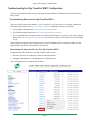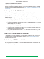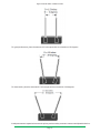
1
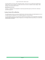
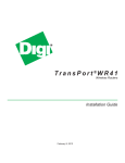
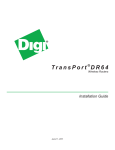
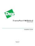
T r a n s P o r t ®W R 11
Wireless Routers
EVDO Model
HSPA+ Model
LTE Model
Installation Guide
90001936_B
July 21, 2014
Digi TransPort® WR11 Installation Guide
Copyright
© 2014 Digi International Inc. All rights reserved.
Digi, Digi International, the Digi logo, Digi TransPort®, and Digi TransPort WR11 are trademarks or registered
trademarks in the United States and other countries worldwide. All other trademarks mentioned in this
document are the property of their respective owners.
Information in this document is subject to change without notice and does not represent a commitment on the
part of Digi International. Digi provides this document “as is,” without warranty of any kind, expressed or implied,
including, but not limited to, the implied warranties of fitness or merchantability for a particular purpose. Digi
may make improvements and/or changes in this manual or in the product(s) and/or the program(s) described
in this manual at any time.
Digi Technical Support Contact Information
United States:
(952) 912-3444 or (877) 912-3444
Other Locations:
+1 (952) 912-3444 or (877) 912-3444
EMEA
+44 870 35 000 35
Online: www.digi.com/support
Email: [email protected]
Page 2
Digi TransPort® WR11 Installation Guide
Preface
This guide describes the installation and configuration procedure for the Digi TransPort WR family of routers.
It is intended to provide sufficient information to be able to connect the device to terminal equipment and
power it on. A complete reference guide to the software features that are available on the product is available
separately in PDF format and can be downloaded from the Digi International web site (www.digi.com).
Disclaimer
Digi International makes no representations or warranties with respect to the contents or use of this manual,
any software drivers or associated application software provided with this product and specifically disclaims
any expressed or implied warranties of merchantability or fitness for any particular purpose.
Digi International reserves the right to modify or revise all or part of this document, its contents, and any
products described herein at any time without prior notification and shall not be responsible for any loss, cost
or damage, including consequential damage, caused by reliance on these materials.
Digi Technical Support Contact Information
United States:
(952) 912-3444 or (877) 912-3444
Other Locations:
+1 (952) 912-3444 or (877) 912-3444
EMEA
+44 870 35 000 35
Safety Notices
1. Please read all instructions before installing and powering the device. You should keep these
instructions in a safe place for future reference.
2. If the power supply shows signs of damage or malfunction, stop using it immediately, turn off the power
and disconnect the power supply before contacting your supplier for a repair or replacement.
3. Changes or modifications not expressly approved by the party responsible for compliance could void the
user’s authority to operate the equipment. Use only the accessories, attachments, and power supplies
provided by the manufacturer – connecting non-approved antennas or power supplies may damage the
device, cause interference or create an electric shock hazard, and will void the warranty.
4. Do not attempt to repair the product. The device contains no electronic components that can be serviced or
replaced by the user. Any attempt to service or repair the device by the user will void the product warranty.
5. Products in the TransPort WR® family are designed for indoor use (except for the WR44 R) and should be
used in an environment that is suitable for computers and other electronic equipment.
6. Ports that are capable of connecting to other apparatus are defined as SELV ports. To ensure conformity
with IEC60950 ensure that these ports are only connected to ports of the same type on other apparatus.
Product Disposal Instructions
The WEEE (Waste Electrical and Electronic Equipment: 2002/96/EC) directive has been introduced to ensure
that electrical/ electronic products are recycled using the best available recovery techniques to minimize the
impact on the environment.
This product contains high quality materials and components which can be recycled. At the end of its life this
product MUST NOT be mixed with other commercial waste for disposal. Check with the terms and conditions
of your supplier for disposal information.
Digi International Ltd WEEE Registration number: WEE/HF1515VU
Page 3
Digi TransPort® WR11 Installation Guide
Special Notes on Safety for Wireless Routers
Digi International products are designed to the highest standards of safety and international standards
compliance for the markets in which they are sold. However, cellular-based products contain radio devices
which require specific consideration. Please take the time to read and understand the following guidance. Digi
International assumes no liability for an end user’s failure to comply with these precautions.
Wireless routers incorporate a wireless radio module. Users should ensure that the
antenna(s) is (are) positioned at least 20 cms away from themselves and other persons
in normal operation.
When in a hospital or other health care facility, observe the restrictions on the use of
mobile phones. Do not use the device in areas where guidelines posted in sensitive
areas instruct users to switch off mobile phones. Medical equipment may be sensitive to
RF energy.
The operation of cardiac pacemakers, other implanted medical equipment and hearing
aids can be affected by interference from cellular terminals such as the wireless routers
when places close to the device. If in doubt about potential danger, contact the physician
or the manufacturer of the device to verify that the equipment is properly shielded.
Pacemaker patients are advised to keep the wireless router away from the pacemaker
while it is on.
Wireless routers must NOT be operated on aircraft. The operation of wireless appliances
in an aircraft is forbidden to prevent interference with communications systems. Failure
to observe these instructions may lead to the suspension or denial of cellular services to
the offender, legal action, or both.
As with any electrical equipment, do not operate the device in the presence of flammable
gases, fumes or potentially explosive atmospheres. Radio devices should not be used
anywhere that blasting operations are taking place.
Wireless routers receive and transmit radio frequency energy when power is on.
Interference can occur if used close to TV sets, radios, computers or inadequately
shielded equipment. Follow any special regulations and always power off your device
wherever forbidden or when it may cause interference or danger.
SOS IMPORTANT! - Wireless routers operate using radio signals and cellular networks
cannot be guaranteed to connect in all possible conditions. Therefore, never rely solely
upon any wireless device for life critical communications.
Warning: For environments where the temperature is 55° C or above, this device must
be installed in a restricted access area.
Page 4
Digi TransPort® WR11 Installation Guide
Table of Contents
Introduction to the Digi TransPort WR11������������������������������������������������������������������������������ 6
Digi TransPort WR11 EVDO Model Specifications����������������������������������������������������������������������������� 6
Digi TransPort WR11 HSPA+ Model Specifications ��������������������������������������������������������������������������� 7
Digi TransPort WR11 LTE-MIMO Model Specifications ��������������������������������������������������������������������� 8
Digi TransPort WR11 Configuration ����������������������������������������������������������������������������������� 10
Digi TransPort WR11 Network Settings ������������������������������������������������������������������������������������������� 10
Digi TransPort WR11 Web Interface������������������������������������������������������������������������������������������������� 10
Digi TransPort WR11 Command Line Interface (CLI)����������������������������������������������������������������������� 13
Troubleshooting the Digi TransPort WR11 Configuration������������������������������������������������ 15
Troubleshooting Resources for Digi TransPort WR11���������������������������������������������������������������������� 15
Unable to Open the TransPort WR11 Web Interface ����������������������������������������������������������������������� 16
Unable to Log in to the Digi TransPort WR11 Web Interface ����������������������������������������������������������� 16
Troubleshooting the LTE-MIMO Antenna Orientation����������������������������������������������������������������������� 16
Appendix A Digi TransPort WR11 Hardware Specifications �������������������������������������������� 19
Appendix B Digi TransPort WR11 Accessories ���������������������������������������������������������������� 20
Digi TransPort WR11 AC Power Supplies���������������������������������������������������������������������������������������� 20
Digi TransPort WR11 Cables������������������������������������������������������������������������������������������������������������ 20
Digi TransPort WR11 Antennas - Cellular����������������������������������������������������������������������������������������� 20
Appendix C Digi TransPort WR11 Certifications���������������������������������������������������������������� 21
International EMC (Electromagnetic Emissions/Immunity/Safety) Standards���������������������������������� 21
FCC certifications and regulatory information (USA only)���������������������������������������������������������������� 21
Industry Canada (IC) certifications��������������������������������������������������������������������������������������������������� 22
Page 5
Digi TransPort® WR11 Installation Guide
Introduction to the Digi TransPort WR11
Digi TransPort WR11 is a full-featured, cellular router offering the flexibility to scale from basic connectivity
applications to enterprise class routing and security solutions. With its high performance architecture, Digi
TransPort WR11 is designed for Wide Area Network connectivity including 2.5G, 3G and 4G networks.
Digi TransPort WR11 offers advanced routing, security and firewall features including stateful inspection firewall
and integrated VPN. Enterprise class protocols incorporate BGP, OSPF and VRRP+, a patented technology
built upon the popular VRRP failover standard providing true auto sensing, auto failure and auto recovery of
any line drop.
Digi TransPort WR11 EVDO Model Specifications
6
N
RA
IT
DIG
RT
O
SP
11
WR
1
al
ign
ce
r
we
Po
S
rvi
Se
2
4
5
3
1. LAN: This Ethernet port connects the device to a 10/100 base-T Local Area Network (LAN). The port is
capable of auto-sensing for speed and wiring, so it can accept both straight-through or cross-over cable
connections.
2. Power Cord Input: This locking power connector connects the device to a power source. The connector
should be inserted and rotated to lock in place.
3. LED Status Indicator - SERVICE: Blinks to show the device’s current network mode.
•
Off: No cellular service
•
1 Blink: 1xRTT
•
2 Blinks:EVDO Rev 0
•
3 Blinks:EVDO Rev A
4. LED Status Indicator - SIGNAL: This LED illuminates steadily when there is a network connection to the
WWAN interface and flashes when data is transmitted or received.
•
Green: Signal strength >= -86dBm
•
Amber: Signal strength between -87dBm and -101dB
5. LED Status Indicator - POWER: This LED illuminates steadily when power is connected.
•
Green: Device on
•
Off:
No power
6. Cellular Antenna Connector: This SMA female connector connects the device’s primary cellular antenna.
Page 6
Digi TransPort® WR11 Installation Guide
Digi TransPort WR11 HSPA+ Model Specifications
8
D
11
WR
P
NS
RA
T
IGI
T
OR
6
1
M2
1
al
ce
SIM
SI
r
we
Po
7
n
Sig
rvi
Se
5
2
4
3
1. LAN: This Ethernet port connects the device to a 10/100 base-T Local Area Network (LAN). The port is
capable of auto-sensing for speed and wiring, so it can accept both straight-through or cross-over cable
connections.
2. Power Cord Input: This locking power connector connects the device to a power source. The connector
should be inserted and rotated to lock in place.
3. LED Status Indicator - SERVICE: This LED blinks to show the device’s current network mode.
•
Off:
No cellular service
•
1 Blink: GPRS mode
•
2 Blinks:EDGE mode
•
3 Blinks:UMTS mode
•
4 Blinks:HSDPA mode
•
5 Blinks:HSUPA mode
4. LED Status Indicator - SIGNAL: This LED illuminates steadily when there is a network connection to the
WWAN interface and flashes when data is transmitted or received.
•
Green: Signal strength >= -86dBm
•
Amber: Signal strength between -87dBm and -101dBm
5. LED Status Indicator - POWER: This LED illuminates steadily when power is connected.
•
Green: Device on
•
Off:
No power
6. SIM Door: Encloses the SIM sockets. The SIM door must be removed to install the SIM cards For
installation details, refer to the Quick Start Guide that came with your device.
Note: To remove the SIM door, hold the device on a flat surface and using a screwdriver, firmly pull the cover
straight up.
7. SIM Sockets: SIM 1 and SIM 2 are for use with the Subscriber Identification Module(s) (SIMs).
8. Cellular Antenna Connector: This SMA female connector connects the device’s primary cellular antenna.
Page 7
Digi TransPort® WR11 Installation Guide
Digi TransPort WR11 LTE-MIMO Model Specifications
8
AN
WW PRI
SP
I
DIG
N
TRA
RT
O
11
WR
9
AN
WW SEC
6
1
E
2
VIC
ER
L
NA
7
R
WE
PO
SIG
S
5
4
3
1. LAN: This Ethernet port connects the device to a 10/100 base-T Local Area Network (LAN). The port is
capable of auto-sensing for speed and wiring, so it can accept both straight-through or cross-over cable
connections.
2. Power Cord Input: This locking power connector connects the device to a power source. The connector
should be inserted and rotated to lock in place.
3. LED Status Indicator - SERVICE: This LED blinks to show the device’s current network mode.
•
Off:
No cellular service
•
1 Blink: GPRS mode
•
2 Blinks:EDGE mode
•
3 Blinks:UMTS mode
•
4 Blinks:HSDPA mode
•
5 Blinks:HSUPA mode
•
6 Blinks: LTE mode
4. LED Status Indicator - SIGNAL: This LED illuminates steadily when there is a network connection to the
WWAN interface and flashes when data is transmitted or received.
•
Green: Signal strength >= -86dBm
•
Amber: Signal strength between -87dBm and -101dBm
5. LED Status Indicator - POWER: This LED illuminates steadily when power is connected.
•
Green: Device on
•
Off:
No power
6. SIM Door: Encloses the SIM sockets. The SIM door must be opened to install the SIM cards. For
installation details, refer to the Quick Start Guide that came with your device.
Note: To open the SIM door, slide the SIM door out and lift it up using your finger.
7. SIM Sockets: SIM 1 and SIM 2 are for use with the Subscriber Identification Module(s) (SIMs).
Page 8
Digi TransPort® WR11 Installation Guide
8. Primary LTE Antenna Connector: This SMA female connector connects the device’s primary cellular
antenna.
9. Secondary LTE Antenna Connector: This SMA female connector connects the device’s secondary
cellular antenna.
Page 9
Digi TransPort® WR11 Installation Guide
Digi TransPort WR11 Configuration
Once you have installed and powered up the device, you need to configure it to communicate with the LAN or
WAN. You can configure the device either using the Command Line Interface (CLI) or the Web Interface. The
recommended configuration option is the Web Interface, which you can access via a web browser such as
Firefox, Internet Explorer or Chrome.
Note: You will not be able to use the device for remote communication until you have subscribed to a
suitable mobile/cellular wireless network service.
Digi TransPort WR11 Network Settings
The default IP address for the LAN port is 192.168.1.1 with a subnet mask of 255.255.255.0. The device has a
DHCP server enabled by default which can assign an appropriate IP address to your PC if the PC is configured
to get an IP address automatically. Alternatively, you can manually configure your PC to be on the 192.168.1.x
network, for example, with an IP address of 192.168.1.2 and subnet mask of 255.255.255.0. Take care to
ensure that the device does not conflict with other devices that may already be on the network.
Digi TransPort WR11 Web Interface
1. Connect to the Web Interface: Open a Web browser (such as Firefox, Internet Explorer, Chrome) on
your PC and navigate to http://192.168.1.1. If successful, you will be prompted to enter a username and
password. The default username is username, and the default password is password. After you have
logged in, it is strongly recommended that you immediately change the default username and password.
2. Configure the Device: The router provides built-in wizards, including a Quick Start Wizard, for easy
LAN configuration. The Quick Start Wizard allows you to configure the following:
•
LAN IP settings
•
DHCP server
Page 10
Digi TransPort® WR11 Installation Guide
Digi TransPort WR11 Provisioning
CDMA provisioning is different from GSM since CDMA (in most cases) does not use a SIM card. The CDMA
module provisioning process creates a CDMA data connection to the mobile carrier network. This authenticates
the modem and retrieves account information which is written to flash memory on the CDMA module itself, not
the Digi’s configuration file. Mobile account information is stored on the CDMA module. Therefore, you cannot
remove provisioning information from the CDMA module by performing a factory reset on the TransPort WR11
device.
If provisioning fails (the device does not obtain a phone number), contact the carrier and verify that the device
has an active account. You will need to provide the MEID of the device which is available under Management
- Network Status > Interfaces > Mobile.
The status of a successfully provisioned CDMA module is shown in the following image. Note that the device
has obtained a phone number.
Page 11
Digi TransPort® WR11 Installation Guide
Verizon Provisioning
For a Verizon device, press the Start button under CDMA Provisioning (Configuration - Networks > Interface
> Mobile) leaving the fields blank as shown in the following image.
Verizon LTE Configuration
If using a Verizon LTE module (WR11-L800 or WR11-L900) and a standard Verizon LTE SIM, the device will
connect by default. If using a custom SIM, regardless of module type, select Use custom APN instead of built-in
APN under the Mobile Service Provider Settings, and enter the apn name (as an example, your.apn.com).
Sprint Provisioning
A Sprint device will automatically start the provisioning process when you power the device on. This process
may take several minutes to complete. If it has sufficient cellular signal strength, a successfully provisioned
device will obtain a mobile phone number, as shown in the following image.
Page 12
Digi TransPort® WR11 Installation Guide
Note: To maintain a reliable cellular connection, it is recommended that you enable Dead Link Detection on
the mobile interface. The SureLink Wizard, located in the Wizard section of the WebUI, will walk you through
the configuration. For additional information on this feature, refer to Application Note AN07 available at www.
digi.com/support.
Digi TransPort WR11 Cellular Configuration (GSM)
To configure the Mobile interface on GSM routers (GPRS/UMTS/HSPA), make sure an activated SIM is
installed in SIM slot 1 and perform the following steps:
1. Browse to Configuration - Network > Interfaces > Mobile > Mobile Settings.
2. Enter the Service Plan / APN provided by your mobile carrier.
3. Enter optional information such as Username, Password and/or SIM PIN as required by your cellular
provider.
4. Click Apply and Save All.
5. If the TransPort does not obtain a MobileIP address as displayed on the home page, refer to Application
Note QN02 and other documentation at www.digi.com/support.
6. To maintain a reliable cellular connection, it is recommended to enable Dead Link Detection on the
mobile interface. The SureLink Wizard, located in the Wizard section of the WebUI, will walk you through
the configuration. For additional information on this feature, refer to Application Note AN07 available at
www.digi.com/support.
Digi TransPort WR11 Command Line Interface (CLI)
The Command Line Interface (CLI) can be accessed via Telnet and SSH using the IP address of the device.
You can do this using an application such as PuTTY (www.putty.org). Log in using your WR11 username and
password.
CLI Notes
•
To view the current configuration settings, enter the command CONFIG C SHOW.
•
To save changes made to the device, enter the command CONFIG 0 SAVE.
Page 13
Digi TransPort® WR11 Installation Guide
•
All entered commands will take effect immediately.
•
All commands supported on the CLI are described in detail in the DigiTransPort User Guide available on
the support site.
Digi TransPort WR11 Communications Settings
The default IP address of the device is 192.168.1.1 and it is configured to act as a DHCP server on the Ethernet
interface. This means the WR11 will assign an IP address to a network device, such as a PC, connected to
the Ethernet interface. The connected device must be configured to obtain an IP address automatically using
DHCP.
Digi TransPort WR11 Network Settings
To configure the device with an IP address as part of an existing network, use the following commands.
Note: The DHCP server will still operate unless it is disabled.
Command
ETH 0 IPADDR XXX.XXX.XXX.XXX
ETH 0 MASK XXX.XXX.XXX.XXX
Description
Sets the Eth 0 IP address
Sets the Eth 0 subnet mask
As an example, to assign the IP address 192.168.10.254/24, enter the following commands.
ETH 0 IPADDR 192.168.10.254
ETH 0 MASK 255.255.255.0
Notes:
•
The IP address configuration takes effect immediately. When you enter the command ETH 0 IPADDR
XXX.XXX.XXX.XXX, any Telnet or SSH connection gets disconnected. You should be able to reconnect
to the new IP address.
•
When you set the mask to the above 255.255.255.0 value, it will not appear in the output of the
CONFIG C SHOW command as it is a default value.
To stop the DHCP server from serving addresses, use the following command.
Command
DHCP 0 IPMIN 0
Description
Removes the minimum IP address that will be served via
DHCP, disabling the DHCP server
As an example, enter the command DHCP 0 IPMIN 0 to stop the DHCP server from responding to DHCP
requests. To revert to defaults, enter DHCP 0 IPMIN !. The ! variable sets the command back to default setting.
To retain the DHCP server, but on a different subnet, configure the following parameters.
Command
DHCP 0 IPMIN X.X.X.X
DHCP 0 IPRANGE
DHCP 0 GATEWAY X.X.X.X
DHCP 0 MASK X.X.X.X
DHCP 0 DNS XXXX
Description
Minimum IP address to assign, the start of the DHCP pool
The number of IP addresses in the DHCP pool
The IP gateway address the DHCP clients should use
(normally this router’s LAN IP address)
The subnet mask DHCP clients should use
The DNS server DHCP clients should use
Page 14
Digi TransPort® WR11 Installation Guide
Troubleshooting the Digi TransPort WR11 Configuration
This section provides information on resources and processes available for troubleshooting your Digi TransPort
WR11 device.
Troubleshooting Resources for Digi TransPort WR11
There are several resources available to you for support of your Digi product or resolving configuration
difficulties at Digi’s Support site, http://www.digi.com/support/. Additional resources are as follows:
1. Digi’s Support knowledge base: http://www.digi.com/support/kbase/.
2. Digi TransPort support documents: http://www.digi/support/documentation/.
3. If the knowledge base or support forums do not have the information you need, fill out an Online Support
Request via: http://www.digi.com/support/login. You will need to create a user account if one is not already
set up.
When submitting a support request, please include a copy of the debug.txt file from the device’s flash. This will
greatly improve the quality of the initial response you receive. Without this file, it is often very difficult for the
support team to provide accurate answers to your queries.
Downloading the debug.txt File from Your Digi TransPort WR11
To download the debug.txt file from your Digi TransPort WR11 device:
1. Browse to the router’s IP address to connect to the Web Interface.
2. Navigate to Administration - File Management > FLASH Directory.
Note: The debug.txt file is usually the last file listed.
Page 15
Digi TransPort® WR11 Installation Guide
3. Right click on debug.txt and click Save target as.
4. Send the debug.txt file as an attachment.
There are several ways to download the debug.txt file from Digi TransPort WR44RR device. For additional
information on the other methods, view the online document QN24 - Extracting the debug.txt file from a Digi
TransPort router.
Unable to Open the TransPort WR11 Web Interface
Ensure that the LAN cable is properly connected to the LAN port and that the LAN status indicator on the
front of the device is illuminated. If it is not, then there is a problem with either the LAN cable or the device
it is connecting to. If the status indicator is illuminated, check that the PC can communicate with the device.
To do this, open the Command Prompt window on your PC and enter the command ping 192.168.1.1.
If you do not get a response, you may have a connection problem. Try one or more of the following steps to
establish a connection.
•
Use the Digi Device Discovery Tool. The IP address of the WR11 device may have been changed from its
default of 192.168.1.1. The Device Discovery Tool can usually discover the device on a network, unless
your system’s firewall is enabled.
•
Check the PC IP configuration. Make sure it is set to obtain an IP address automatically. If not, configure
it to automatically obtain the IP address.
•
Refresh the PC’s IP settings by opening a command window and entering ipconfig/release then
ipconfig/renew.
•
Check the PC’s LAN connection and any LAN device (such as an Ethernet switch) that connects to the
unit. Make sure the PC is connected to the network.
•
Clear the PC’s ARP cache with the command arp –d *, then retry the ping command. If you do get
a response but are unable to view the Web Interface, then there is most likely a problem with your web
browser configuration.
Unable to Log in to the Digi TransPort WR11 Web Interface
If you are unable to log in to the Web Interface, you will need to access the device via Telnet or SSH in order
to configure it using the Command Line Interface (CLI). Please refer to the Digi TransPort User Guide for
information on how to use the CLI.
Troubleshooting the LTE-MIMO Antenna Orientation
The two antennas should be separated at the maximum distance possible, taking into consideration the
available space of the installation. There should be a minimum distance of 1.5 inches between two antennas
as shown in the following image.
Page 16
Digi TransPort® WR11 Installation Guide
For good performance, place the antenna 4.5 inches apart with an orientation of 30 degrees.
For best results, place the antennas 8.5 inches apart with an orientation of 60 degrees.
Inadequate antenna separation between the primary and secondary antennas creates unanticipated behaviors.
Page 17
Digi TransPort® WR11 Installation Guide
These include:
•
Reduced antenna efficiency, which limits:
◦◦
Transmit power
◦◦
Receiver sensitivity (RSSI)
◦◦
Data throughput
Inadequate antenna separation can also have negative long-term effects on the cellular radio, reducing overall
product lifespan.
Do not place the antennas in the following positions:
Page 18
Digi TransPort® WR11 Installation Guide
Appendix A Digi TransPort WR11 Hardware Specifications
Specifications
Digi TransPort WR11
General Features:
Dimensions
(L x W x H)
3.9” x 5.2” x 1.3”
Weight
0.85 lbs.
(10 cm x 13.1 cm x 3.2 cm)
Cellular:
EDGE
850, 900, 1800, 1900 MHz
GSM
UMTS / HSPA 800/850, 900, 1700 (AWS), 1900, 2100 MHz
CDMA
1xRTT 800, 1900 MHz
EVDO
800, 1900 MHz
LTE – AT&T
700 (B17) / 850 (B5) / AWS1700 (B4) / 1900 (B2)
LTE – Verizon
700 (B13) / AWS1700 (B4)
LTE – Worldwide
800 (B20) / 1800 (B3) / 2600 (B7)
Power Requirements:
Power input
Voltage
5V dc ± 5%
Power
3.5W typ, 15W MAX
Connector
Locking barrel
Environmental:
Operating temperature
0°C to 40°C required
Relative humidity
5% to 90% (non-condensing)
Storage temperature
-40° C to +80° C
RoHS compliance
Yes
Approvals:
Mobile certifications - GSM
AT&T & PTCRB
Mobile certifications - EVDO
Sprint & Verizon
Mobile certifications - LTE
AT&T; Verizon; PTCRB
Wireless carrier certifications
Certified by most major carriers.
Page 19
Digi TransPort® WR11 Installation Guide
Appendix B Digi TransPort WR11 Accessories
The following sections provide the list of Digi TransPort WR11 accessories with the corresponding part numbers.
Digi TransPort WR11 AC Power Supplies
AC Power Supplies
Part Number
5V 3.0A 2.5mm Locking, U.S. Plug
76000934
5V 3.0A 2.5mm Locking, International Plug Kit
76002021
Digi TransPort WR11 Cables
Cables
Part Number
RJ45 to RJ45 crossover - 0.5m
76000932
RJ45 to RJ45 - 2m
76000826
RJ45 to RJ45 - 12’
76000828
RJ45 to RJ45 crossover - 12’
76000829
SMA male to SMA female - 5m
76000830
SMA male to SMA female - 10m
76000831
SMA male to SMA female - 15m
76000832
Digi TransPort WR11 Antennas - Cellular
Antennas - Cellular
Part Number
Direct mount, penta band, 2dBi
76002052
Direct mount, dual band, 3dBi
DC-ANT-DBDP3
Direct mount, penta band, 3.0dBi
76000793
Direct Mount, LTE Multi-Band
76000926
Magnet mount, penta band, 2.5dBi
76002051
Magnet mount, dual band, 4.0dBi
DC-ANT-DBHG
Glass mount, quad band, 1.5dBi
76000844
Glass mount, penta band, 0dBd
76000845
Surface/Marine mount, quad band, 0dBi - 2.15dBi
76000864
Surface/Through-hole mount, quad band, 0dBd
76000846
Surface/Through-hole mount, quad band, 3.15dBi
76000847
Page 20
Digi TransPort® WR11 Installation Guide
Appendix C Digi TransPort WR11 Certifications
Digi TransPort WR11 complies with the requirements of the following International Electromagnetic
Compatibility (EMC) standards.
International EMC (Electromagnetic Emissions/Immunity/Safety) Standards
Digi TransPort WR11 complies with the requirements of the following Emissions, Immunity and Safety
standards.
Emissions
Immunity
Safety
EN 55022: 2010 Class B
EN 550024:2010
EN 60950-1: :2006 + A1:2010 +
A11:2009 + A12:2011
FCC 15.109(g):2014 Class B
FCC 15.109:2014 Class B
ICES-003:2012 Class B
IEC 60950-1:2005+ A1:2009
EN 55022: 2010 Class B
FCC 15.107:2014 Class B
ICES-003:2012 Class B
EN 301 489-07 V1.3.1:2005
EN 61000-3-2:2006 (Amended by
A1:2009 and A2:2009) Class B
UL 60950-1 2nd Ed. Revised
2011-12-19
EN 61000-3-3:2008 Class B
EN 301 489-07 V1.3.1:2005 Class B
CSA C22.2 No. 60950-1 -07 +
A1:2011
There are no user-serviceable parts inside the product. Contact your Digi representative through Digi contact
information for repair information.
FCC certifications and regulatory information (USA only)
FCC Part 15 Class B
Radio Frequency Interface (RFI) (FCC 15.105)
This device has been tested and found to comply with the limits for Class B digital devices pursuant to
Part 15 Subpart B, of the FCC rules. These limits are designed to provide reasonable protection against
harmful interference in a residential environment. This equipment generates, uses, and can radiate radio
frequency energy, and if not installed and used in accordance with the instruction manual, may cause harmful
interference to radio communications. However, there is no guarantee that interference will not occur in a
particular installation. If this equipment does cause harmful interference to radio or television reception,
which can be determined by turning the equipment off and on, the user is encouraged to try and correct the
interference by one or more of the following measures:
•
Reorient or relocate the receiving antenna.
•
Increase the separation between the equipment and receiver.
•
Connect the equipment into an outlet on a circuit different from that to which the receiver is connected.
•
Consult the dealer or an experienced radio/TV technician for help.
Labeling Requirements (FCC 15.19)
This device complies with Part 15 of FCC rules. Operation is subject to the following two conditions: (1)
this device may not cause harmful interference, and (2) this device must accept any interference received,
Page 21
Digi TransPort® WR11 Installation Guide
including interference that may cause undesired operation. If the FCC ID is not visible when installed inside
another device, then the outside of the device into which the module is installed must also display a label
referring to the enclosed module FCC ID.
Modifications (FCC 15.21)
Changes or modifications to this equipment not expressly approved by Digi may void the user’s authority to
operate this equipment.
Industry Canada (IC) certifications
This digital apparatus does not exceed the Class B limits for radio noise emissions from digital apparatus set out in
the Radio Interference Regulations of the Canadian Department of Communications.
Le present appareil numerique n’emet pas de bruits radioelectriques depassant les limites applicables aux appareils
numeriques de la class B prescrites dans le Reglement sur le brouillage radioelectrique edicte par le ministere des
Communications du Canada.
Page 22
Digi International Inc.
11001 Bren Road East
Minnetonka, MN 55343
952-912-3444 or 877-912-3444