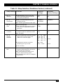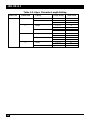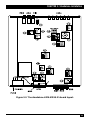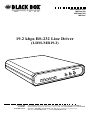
1
SEPTEMBER 2002
ME760A-R2
ME760AE-R2
ME760C
19.2 kbps RS-232 Line Driver
(LDM-MR19.2)
CUSTOMER
SUPPORT
INFORMATION
Order toll-free in the U.S. 24 hours, 7 A.M. Monday to midnight Friday: 877-877-BBOX
FREE technical support, 24 hours a day, 7 days a week: Call 724-746-5500 or fax 724-746-0746
Mail order: Black Box Corporation, 1000 Park Drive, Lawrence, PA 15055-1018
Web site: www.blackbox.com • E-mail: [email protected]
FCC AND IC STATEMENTS
FEDERAL COMMUNICATIONS COMMISSION
AND
INDUSTRY CANADA
RADIO FREQUENCY INTERFERENCE STATEMENTS
This equipment generates, uses, and can radiate radio frequency energy and if not
installed and used properly, that is, in strict accordance with the manufacturer’s
instructions, may cause interference to radio communication. It has been tested
and found to comply with the limits for a Class A computing device in accordance
with the specifications in Subpart J of Part 15 of FCC rules, which are designed to
provide reasonable protection against such interference when the equipment is
operated in a commercial environment. Operation of this equipment in a
residential area is likely to cause interference, in which case the user at his own
expense will be required to take whatever measures may be necessary to correct
the interference.
Changes or modifications not expressly approved by the party responsible
for compliance could void the user’s authority to operate the equipment.
This digital apparatus does not exceed the Class A limits for radio noise emission from
digital apparatus set out in the Radio Interference Regulation of Industry Canada.
Le présent appareil numérique n’émet pas de bruits radioélectriques dépassant les limites
applicables aux appareils numériques de classe A prescrites dans le Règlement sur le
brouillage radioélectrique publié par Industrie Canada.
1
LDM-MR19.2
NORMAS OFICIALES MEXICANAS (NOM)
ELECTRICAL SAFETY STATEMENT
INSTRUCCIONES DE SEGURIDAD
1. Todas las instrucciones de seguridad y operación deberán ser leídas antes
de que el aparato eléctrico sea operado.
2. Las instrucciones de seguridad y operación deberán ser guardadas para
referencia futura.
3. Todas las advertencias en el aparato eléctrico y en sus instrucciones de
operación deben ser respetadas.
4. Todas las instrucciones de operación y uso deben ser seguidas.
5. El aparato eléctrico no deberá ser usado cerca del agua—por ejemplo, cerca
de la tina de baño, lavabo, sótano mojado o cerca de una alberca, etc..
6. El aparato eléctrico debe ser usado únicamente con carritos o pedestales que
sean recomendados por el fabricante.
7. El parato eléctrico debe ser montado a la pared o al techo sólo como sea
recomendado por el fabricante.
8. Servicio—El usuario no debe intentar dar servicio al equipo eléctrico más allá
a lo descrito en las instrucciones de operación. Todo otro servicio deberá ser
referido a personal de servicio calificado.
9. El aparato eléctrico debe ser situado de tal manera que su posición no
interfiera su uso. La colocación del aparato eléctrico sobre una cama, sofá,
alfombra o superficie similar puede bloquea la ventilación, no se debe
colocar en libreros o gabinetes que impidan el flujo de aire por los orificios
de ventilación.
2
NOM STATEMENT
10. El equipo eléctrico deber ser situado fuera del alcance de fuentes de calor
como radiadores, registros de calor, estufas u otros aparatos (incluyendo
amplificadores) que producen calor.
11. El aparato eléctrico deberá ser connectado a una fuente de poder sólo del
tipo descrito en el instructivo de operación, o como se indique en el aparato.
12. Precaución debe ser tomada de tal manera que la tierra fisica y la polarización
del equipo no sea eliminada.
13. Los cables de la fuente de poder deben ser guiados de tal manera que no
sean pisados ni pellizcados por objetos colocados sobre o contra ellos,
poniendo particular atención a los contactos y receptáculos donde salen
del aparato.
14. El equipo eléctrico debe ser limpiado únicamente de acuerdo a las
recomendaciones del fabricante.
15. En caso de existir, una antena externa deberá ser localizada lejos de las lineas
de energia.
16. El cable de corriente deberá ser desconectado del cuando el equipo no sea
usado por un largo periodo de tiempo.
17. Cuidado debe ser tomado de tal manera que objectos liquidos no sean
derramados sobre la cubierta u orificios de ventilación.
18. Servicio por personal calificado deberá ser provisto cuando:
A: El cable de poder o el contacto ha sido dañado; u
B: Objectos han caído o líquido ha sido derramado dentro del aparato; o
C: El aparato ha sido expuesto a la lluvia; o
D: El aparato parece no operar normalmente o muestra un cambio
en su desempeño; o
E: El aparato ha sido tirado o su cubierta ha sido dañada.
3
LDM-MR19.2
TRADEMARK USED IN THIS MANUAL
AS/400 is a registered trademark of International Business Machines Corporation.
Any other trademarks mentioned in this manual are acknowlegded to be the property
of the trademark owners.
4
TABLE OF CONTENTS
Contents
Chapter
Page
1.
Specifications ............................................................................................. 6
2.
Introduction ............................................................................................. 10
2.1 Functional Description ..................................................................... 11
2.2 Applications ....................................................................................... 15
3.
Standalone Installation ............................................................................
3.1 Complete Package ............................................................................
3.2 Physical Placement ............................................................................
3.3 Data Cables ........................................................................................
3.4 Setting the Internal Controls ...........................................................
3.5 AC Power Cord ..................................................................................
18
18
18
18
21
21
4. Card Installation .........................................................................................
4.1 The RackNest 2/14 ...........................................................................
4.2 The RackNest 2/14’s Power Supply .................................................
4.3 The RackNest 2/14 Illustrated .........................................................
4.4 Card-Configuration Procedure ........................................................
4.5 Card-Installation Procedure .............................................................
26
26
27
28
31
35
5.
Operation .................................................................................................
5.1 Controls and Indicators ....................................................................
5.2 Turning the Unit ON .......................................................................
5.3 Operating Procedure ........................................................................
5.4 Remote Power Failure (RPF) ...........................................................
5.5 Turning the Unit OFF ......................................................................
5.6 Reconfiguration ................................................................................
36
36
39
39
39
40
40
6.
Troubleshooting ......................................................................................
6.1 Loopback Testing .............................................................................
6.2 Calling Black Box ..............................................................................
6.3 Shipping and Packaging ...................................................................
41
41
44
44
5
LDM-MR19.2
1. Specifications
Compliance —
FCC Part 15 Subpart J Class A, DOC Class/MDC classe A
Cable Required — Between ME760 units: Unloaded twisted pair, 19 to
26 gauge; 4 wires for full duplex, at least 2 wires for
half-duplex; DC continuity not required;
Between standalone ME760 unit and DTE: TIA RS-232
cable with DB25 male connector on ME760 end
Interface —
Serial EIA RS-232-D/CCITT V.24, DCE
Protocol —
Synchronous or asynchronous
Clock Source —
Either internal, external from local DTE, or recovered
from remote LDM-MR19.2
Data Format —
5, 6, 7, or 8 data bits; 1, 1.5, or 2 stop bits; even, odd, or
no parity (but see Table 3-3 on page 26)
Operation —
2– or 4-wire half-duplex or 4-wire full-duplex; point-topoint or multipoint
Data Rate —
Sync: 1.2, 2.4, 3.6, 4.8, 7.2, 9.6, 14.4, or 19.2 Kbps;
Async: Up to 19.2 Kbps
RTS/CTS Delay — 0, 8, or 64 ms (user-selectable)
Modulation —
Differential diphase Eurocom Standard D1
Transmit Level —
0, –3, –6, or –9 dBm (user-selectable)
Transmit
Impedance —
600, 300, or 150 ohms or “LOW” (user-selectable)
Receive
Impedance —
150, 300, or 600 ohms or “HIGH” (user-selectable)
Return Loss —
Greater than 15 dB
6
CHAPTER 1: Specifications
Carrier —
Controlled by RTS or constantly ON (user-selectable)
Maximum
Transmission
Distance —
See Table 1-1 on page 11
User Controls —
(3 or 4) Front-mounted pushbuttons:
DIG (local digital loopback);
ANA (local analog loopback);
REM (remote digital loopback);
ME760C only: RPF (reset after remote power failure);
(15 or 16) Internal:
(1) Dial for data rate;
(1) Four-position DIP switch for async character length
and stop-bit shortening;
(13 or 14) Jumpers:
Transmit timing;
2- or 4-wire operation;
CTS delay;
Carrier control;
Transmit level;
Transmit-line impedance;
Receive-line impedance;
Enable/disable analog-loopback command on Pin 18;
Enable/disable remote-loopback command on Pin 21;
Enable/disable front-panel pushbuttons;
Connect/disconnect signal ground and chassis ground;
AGC control;
Activate/deactivate V.54 delay;
ME760A(E)-R2 only: Enable/disable RPF tone
Diagnostics —
Comply with V.54 standard:
Local analog loopback, mechanically or electrically
user-controllable;
Local digital loopback, mechanically user-controllable;
Remote digital loopback, mechanically or electrically
user-controllable
7
LDM-MR19.2
Indicators —
(6 or 7) Front-mounted LEDs: PWR (power), RTS, TD,
RD, DCD, TEST, and (ME760C only) RPF (remote
power failure)
Connectors —
(2) Rear-mounted: (1) DB25 for cable to DTE,
(1) 4-wire terminal block for modem-to-modem line
Power —
Directly from outlet through detachable 5-ft. (1.5-m) line
cord and rear-mounted IEC 320 male inlet:
ME760A: 115 VAC, 47 to 63 Hz, 3 watts; input cord
terminated with N. American standard NEMA 5-15P
plug;
ME760AE: 230 VAC, 47 to 63 Hz, 3 watts; input cord
unterminated when shipped, terminated by user
Protection —
AC/DC overvoltage-protection circuits connected
through transformers to transmit and receive lines
Mean Time
Between Failures — 163,000 hours
Temperature
Tolerance —
32 to 158˚ F (0 to 70˚ C)
Humidity
Tolerance —
0 to 90% noncondensing
Enclosure —
High-impact plastic
Size —
1.6"H x 9.6"W x 7.6"D (4 x 24.4 x 19.3 cm)
Weight —
3.1 lb. (1.4 kg)
8
CHAPTER 1: Specifications
Table 1-1. Maximum Transmission Distance.
SPEED
(bps)
19 AWG
24 AWG
26 AWG
19,200
6 mi. (9.8 km)
4 mi. (6.5 km)
2.7 mi. (4.4 km)
14,400
7.5 mi. (12.1 km)
5 mi. (8.1 km)
3.4 mi. (5.4 km)
9,600
9.8 mi. (15.8 km)
6.5 mi. (10.5 km)
7,200
10.5 mi. (17.3 km)
7 mi. (11.5 km)
4.7 mi. (7.7 km)
4,800
13.5 mi. (21.8 km)
9 mi. (14.5 km)
6 mi. (9.7 km)
3,600
15 mi. (24 km)
10 mi. (16 km)
6.7 mi. (10.7 km)
2,400
16.5 mi. (27 km)
11 mi. (18 km)
7.4 mi. (12 km)
1,800
19.5 mi. (30.8 km)
13 mi. (20.5 km)
8.7 mi. (13.7 km)
1,200
22.5 mi. (36 km)
15 mi. (24 km)
4.4 mi. (7 km)
10.1 mi. (16 km)
9
LDM-MR19.2
2. Introduction
The 19.2 kbps RS-232 Line Driver (LDM-MR19.2 for short) is a short-range
modem which operates at full- or half-duplex with synchronous or asynchronous
transmission over unconditioned telephone lines. With an extended range of up
to 34 miles (55 km), the LDM-MR19.2 operates at any of eight selectable data rates,
up to 19,200 bps.
By using conditioned differential diphase modulation (Eurocom Std. D1), the
LDM-MR19.2 provides immunity from background noise, eliminates normal line
distortion, and enables efficient transmission and reception of serial data over
twisted-pair cable.
The LDM-MR19.2 is coupled to the telephone line through isolation
transformers. The transformers and electronic circuitry protect against AC or DC
overvoltages. The protection circuitry allows operation even when DC is connected
to the line, because of the following features:
• Transmit Level and Transmit and Receive Impedances are independently
selectable.
• Transmit timing is provided internally, derived externally from the
data terminal, or regenerated from the Receive signal.
• Receive timing is regenerated from the Receive signal.
Line communication is always synchronous. When you set the LDM-MR19.2 to
asynchronous mode, it performs an async-to-sync conversion in compliance with
the CCITT V.22 bis standard.
The LDM-MR19.2 also features V.54 diagnostic capabilities for performing local
analog loopback and local and remote digital loopback. In the digital loopback
mode, the operator at either end of the line may test both of the modems and
the line. The operator can control the loopback with either the front-panel
pushbuttons or Pins 18 and 21 of the V.24/RS-232 interface.
10
CHAPTER 2: Introduction
2.1 Functional Description
This section contains functional descriptions of the LDM-MR19.2’s circuit blocks
(primarily the circuits required for correctly configuring the unit).
2.1.1 ENCODER
The encoder modulates the input data from the DTE using the “conditional
diphase modulation” technique. You can configure the encoder to operate in
one of five modes:
• 4-wire full-duplex
• 4-wire half-duplex
• 2-wire half-duplex
• 4-wire multipoint
• 2-wire multipoint
2.1.2 MODULATION TIMING
The modulation-timing circuit supplies the Transmit clock to the encoder. Four
clock sources are available:
• INT.CK (internal clock—from the modem’s internal crystal oscillator)
• EXT.CK (external clock—from DTE, Pin 24)
• RCV.CK (receive clock—recovered from Receive signal)
• ASYNC (asynchronous timing for working with the async-to-sync converter
in an async application)
Setting the XMT TIMING jumpers determines the timing option.
11
LDM-MR19.2
2.1.3 ASYNC-TO-SYNC CONVERTER
The LDM-MR19.2 provides internal conversion from async to sync in compliance
with CCITT V.22 bis. According to this standard, frequency deviation between the
modem and the DTE is compensated for by shortening or lengthening the stop bit
of the async character. When the modem’s frequency is higher than the DTE’s, the
local converter extends the stop bit. When the modem’s frequency is lower than
the DTE’s, the local converter may delete one stop bit every four or eight
characters. The remote converter adds a shorter stop bit before sending the
data to the remote DTE.
For frequency deviations of up to 1.1%, the stop bits should be shortened every
eight characters (12.5%). For frequency deviations of 1.2% to 2.3%, the stop bits
should be shortened every four characters (25%).
Use switch position 2 (S2) of the “ASYNC LENGTH” DIP switch to select 25% or
12.5% frequency deviation. For proper operation of the async-to-sync converter, set
the async character length by adjusting switch positions 3 and 4 (S3 and S4) of the
“ASYNC LENGTH” DIP switch. See Table 3-3 on page 26 for detailed settings.
2.1.4 XMT LEVEL
Four options are available for the XMT level (signal level): 0, –3, –6, or –9 dBm.
XMT level is controlled by the XMT LEVEL jumper.
12
CHAPTER 2: Introduction
2.1.5 RECEIVER
The receiver contains several circuits (shown in Figure 2-1 below):
• The RECEIVE FILTER removes all the out-of-band frequencies.
• The AUTOMATIC EQUALIZER is made up of several equalizers activated
according to data rate.
• The digital AGC (automatic gain control) automatically compensates for
the attenuation of the line. You can choose between the two modes of AGC
operations by setting the AGC jumper:
ON: The AGC operates continuously.
CNTR: The AGC is active only when DCD is ON. When DCD is OFF,
the AGC will remain in the state to which it was most recently set.
In full-duplex point-to-point applications, there is no difference between the
two AGC modes of operation.
Figure 2-1. Block diagram for the LDM-MR19.2.
13
LDM-MR19.2
However, there is a difference in multipoint applications, where the master
modem communicates with modems at different distances. When the master
modem is set to AGC-ON, the master can communicate across long distances (up
to its maximum range) to the slave modems. However, this setting increases the
RTS-to-CTS delay. For example, under AGC-ON, the CTS delay of all slaves must
be set to 64 ms when the data rate is less than 9.6 Kbps.
When the master modem is set to AGC-CNTR, it can’t transmit or receive across
as much distance. However, the polling goes faster. For example, under AGCCNTR, the CTS delay of all units can be set to 8 ms when the data rate is greater
than or equal to 4.8 Kbps.
Table 2-1, below, contains general guidelines for choosing AGC and CTS-delay
settings. Each application is unique, however; you might find that your LDMMR19.2 system works better when the units are set slightly differently.
Table 2-1. Recommended Multipoint AGC and CTS-Delay Settings
Distance
Between
Modems*
Data Rate
Master
AGC
Master
CTS Delay
Slave
AGC
Slave
CTS Delay
Short range
≤2.4 Kbps
CNTR
64 ms
CNTR
64 ms
Short range
>2.4 Kbps,
CNTR
8 or 64 ms
ON
64 ms
CNTR
8 or 64 ms
ON
8 or 64 ms
<4.8 Kbps
Short range
≥4.8 Kbps
Long range
<9.6 Kbps
ON
8 or 64 ms
ON
64 ms
Long range
≥9.6 Kbps
ON
8 or 64 ms
ON
8 or 64 ms
* “Short range” = up to 2.8 mi. (4.5 km) for data rates of 9.6 or 19.2 Kbps or up to 3.7 mi. (6 km)
for data rates of 3.6 to 7.2 Kbps. “Long range” represents distances greater than these.
14
CHAPTER 2: Introduction
2.1.6 V.54 DIAGNOSTICS
You can activate V.54 loops with either the front-panel pushbuttons or Pins 18
and 21 of the V.24/ RS-232 interface. The pushbuttons, Pin 18, and Pin 21 can
be enabled or disabled separately by the SWITCH, PIN 18, and PIN 21 jumpers,
respectively.
When you use the LDM-MR19.2 as a tail end to a DDS network, set the V.54
DELAY jumpers of the modems located close to the DDS network to ON to
prevent multiple loopbacks. The DELAY switch prevents the last modem from
receiving the complete V.54 data sequence and being induced into a loop. V.54
is required only for operation in synchronous mode.
NOTE
The V.54 DELAY jumper must be set to OFF when you operate
in asynchronous mode.
2.2 Applications
Figures 2-2 through 2-5 on the next two pages illustrate the LDM-MR19.2 in various
configurations.
(text continues on page 18)
15
LDM-MR19.2
4-wire twisted pair,
up to 34 mi. (55 km)
LDM-MR19.2
LDM-MR19.2
PC running
PC
emulation
software
®
AS/400
A/S
400
Figure 2-2. Point-to-point application.
LDM-MR19.2
LDM-MR19.2
SLAVE 1
XMT IMP.-150Ω
RCV IMP.-HIGH
LDM-MR19.2
SLAVE 2
XMT IMP.-150Ω
RCV IMP.-HIGH
LDM-MR19.2
SLAVE 3
XMT IMP.-150Ω
RCV IMP.-HIGH
LDM-MR19.2
SLAVE N
XMT IMP.-150Ω
RCV IMP.-150Ω
MASTER
XMT IMP.-LOW
RCV IMP.-150Ω
AS/400
A/S
400
Figure 2-3. Multipoint application.
16
CHAPTER 2: Introduction
LDM-MR19.2:
RCV CLOCK,
V.54 DLY–OFF
PC running
5250 emulation
software
LDM-MR19.2:
EXT CLOCK,
V.54 DLY–ON
CSU/DSU
Cross-pinned cable
such as our EYN255C
DIGITAL
SERVICE
NETWORK
CSU/DSU
AS/400
Figure 2-4. Tail circuit for DDS application.
The XMT and
RCV
impedances
of all the
LDM-MR19.2s
in this
application
would be set
to 150 ohms.
MASTER
LDM-MR19.2
SLAVE LDM-MR19.2
Controller
SLAVE LDM-MR19.2
Controller
SLAVE LDM-MR19.2
Controller
AS/400
Figure 2-4. Star application.
17
LDM-MR19.2
3. Standalone Installation
Follow the directions in this chapter to install the standalone version of the
LDM-MR19.2. Once you’ve done this, see Chapter 5 for operating information.
3.1 Complete Package
With your LDM-MR19.2 order, you should have received (1) LDM-MR19.2,
(1) detachable 5-ft. (1.5-m) AC power cord, and (1) copy of this manual. The
LDM-MR19.2 is fully assembled at the factory. You don’t have to assemble any
part of the unit. However, you will have to attach an appropriate plug to the
power cord if your unit is a 230-VAC (ME760AE-R2) model.
3.2 Physical Placement
Place the LDM-MR19.2 on a tabletop or bench within 5 feet (1.5 m) of a grounded
3-wire AC outlet and within 50 feet (15.2 m) of the associated data terminal. The
unit is not designed to be bolted down.
Allow at least 36 inches (90 cm) of clearance in front of the unit so you can
operate and maintain it. Be sure to leave 4 inches (10 cm) of clearance behind
the unit for signal lines and interface cables.
3.3 Data Cables
The LDM-MR19.2’s data-communication connectors (a five-crimp terminal
block and a DB25 connector) are on its rear panel (see Figure 3-1 below).
DTE
XMT
115 VAC/
RCV
GND
- 0.2A T 250V
J1
TB1
Figure 3-1. The LBM-MR19.2’s rear panel (ME760A-R2 model shown).
18
CHAPTER 3: Standalone Installation
The terminal block holds five crimp-style contact positions for connecting the
Transmit (XMT) and Receive (RCV) telephone lines. The Transmit and Receive
pairs are not polarity-sensitive. Using a screwdriver to gently lever open the
contacts, connect the Transmit pair to the XMT terminals; for 2-wire operation,
this is all you need. For 4-wire operation, connect the Receive pair to the RCV
terminals, making sure that local XMT is connected to remote RCV and local RCV
is connected to remote XMT. If you are using shielded cable, there is also a fifth
terminal for optional ground connection (at one end only!).
For detailed information on the pinout of the DB25 connector, see Table 3-1
below and on the next page.
Table 3-1. DB25 Pinout and Interface-Signal List
CCITT
V.24
EIA
RS-232-C
DTE
PIN
SIGNAL
NAME
101
AA
1
Protective
Ground
Chassis ground. Can be isolated from
Signal Ground (refer to GND Strap in
Table 3-2).
102
AB
7
Signal Ground
Common signal; DC-power-supply ground.
N/A
N/A
9
10
+8 volts
–8 volts
Output +8 VDC
Output –8 VDC
103
BA
2
Transmitted
Data
Serial digital data received from (sent by) the
local DTE. See the Note on the next page.
104
BB
3
Received
Data
Serial digital data sent to (received by) the
local DTE. See the Note on the next page.
105
CA
4
Request to
Send
Local DTE sends a “high” (positive) level to
the LDM-MR19.2 when it wants to send data.
106
CB
5
Clear to Send
After receiving a Request to Send from the
local DTE, the LDM-MR19.2 waits for a
user-selectable period, then sends a “high”
(positive) level to the DTE to signal that it is
ready to receive data.
107
CC
6
Data Set Ready
The LDM-MR19.2 always sends a “high”
(positive) level to the local DTE except when
the LDM-MR19.2 is in local or remote digital
loopback.
DESCRIPTION
19
LDM-MR19.2
Table 3-1. DB25 Pinout and Interface-Signal List (continued)
CCITT
V.24
EIA
RS-232-C
DTE
PIN
SIGNAL
NAME
109
CF
8
Receive Line
Signal Detector
(Carrier Detect)
The LDM-MR19.2 always sends a “high”
(positive) level to the local DTE except when
the LDM-MR19.2 detects carrier loss or is in
local or remote digital loopback.
113
DA
24
External Trans.
Signal Element
Timing
Synchronous data-rate-clock input received
from the local DTE. Governs the Transmitted
Data signal. See the Note below.
114
DB
15
Transmitter
Signal Element
Timing
Synchronous data-rate-clock output sent to
the local DTE. Governs the Transmitted Data
signal. See the Note below.
115
DD
17
Receiver Signal
Element Timing
Synchronous data-rate-clock output sent to
the local DTE. Governs the Received Data
signal. See the Note below.
142
25
Test Indicator
The LDM-MR19.2 sends a “high” (positive)
level to the local DTE during any test mode.
141
18
Loop 3
Test Command
When it receives this control signal from the
local DTE, the LDM-MR19.2 goes into Local
Analog Loopback.
140
21
Loop 2
Test Command
When it receives this control signal from the
local DTE, the LDM-MR19.2 forces the
remote modem into Remote Digital Loopback.
DESCRIPTION
NOTE: When the LDM-MR19.2 is operating synchronously, transitions of the Transmitted Data and
Received Data signals happen at the same time as positive-going (“rising edge”) transitions of the active
clock signal.
20
CHAPTER 3: Standalone Installation
3.4 Setting the Internal Controls
After you install the cabling, you’ll need to configure the LDM-MR19.2 for your
application by setting its internal straps (jumpers) and switches as necessary. The
numbers listed under the “Strap Identity” column in Table 3-2 on the next two
pages correspond to the numbered strap locations in Figure 3-2 on page 27.
CAUTION!
Be sure the LDM-MR19.2 is unplugged before you open it.
To set internal jumpers and switches, follow the steps below.
1. Loosen the screw holding the top cover in place (located at the top
of the rear panel).
2. Remove the top cover.
3. Adjust the jumpers and switches for the configuration you want.
4. Replace the top cover and tighten the retaining screw.
3.5 AC Power Cord
Plug the LDM-MR19.2’s power cord into a grounded 3-wire AC outlet.
Your LDM-MR19.2 should now be ready for continuous operation.
(text continues on page 26)
21
LDM-MR19.2
Table 3-2. Strap Selection, Standalone Version
22
Strap Identity Function
Possible
Settings
Standard
Factory Settings
No. 1
DATA RATE
(Kbps)
Determines the data rate.
0 = 19.2 Kbps
1 = 14.4 Kbps
2 = 9.6 Kbps
3 = 7.2 Kbps
4 = 4.8 Kbps
5 = 3.6 Kbps
6 = 2.4 Kbps
7 = 1.2 Kbps
No. 2
XMT TIMING
Determines whether the transmit-timing
signal comes from the internal clock,
external clock, or receive clock, or
whether the unit operates in async.
INT
EX
RCV
ASY
No. 3
2W/4W
Determines whether the unit uses
2 wires or 4 wires.
2W
4W
No. 4
CTS DELAY
Determines the RTS-to-CTS delay.
0 ms
8 ms
64 ms
No. 5
CARRIER
Determines the transmit carrier mode.
ON: Transmit carrier is constantly ON.
CTRL: Transmit carrier is ON only when
RTS is high.
CTRL should be used in multipoint
applications.
ON
CTRL
ON
No. 6
XMT LEVEL
Determines transmit-output level to the
line.
0 dBm
–3 dBm
–6 dBm
–9 dBm
0 dBm
No. 7
XMT IMPD
Determines transmit-line impedance.
For multipoint applications, set the
master modem to LOW.
600
300
150
LOW
No. 8
RCV IMPD
Determines receive-line impedance.
For multipoint applications, set the
master modem and the last modem in
line to 150; set all others to HIGH.
150
300
600
HIGH
150 [ohms]
No. 9
PIN 18
Enables/disbales analog-loopback
command from the DTE on Pin 18.
EN
DIS
EN
No. 10
PIN 21
Enables/disables remote-loopback
command from the DTE on Pin 21.
RLB EN
RLB DIS
RLB EN
2 = 9.6 Kbps
INT (internal clock)
4W (4 wires)
8 ms
150 [ohms]
CHAPTER 3: Standalone Installation
Table 3-2. Strap Selection, Standalone Version (continued)
Strap Identity Function
Possible
Settings
Standard
Factory Settings
No. 11
SWITCH
Enables/disables control of the DIG,
ANA, and REM loopbacks with the
front-panel pushbuttons.
DIS
EN
EN
No. 12
CHAS GND
CONN.: Connects Signal Ground to
Chassis Ground.
DIS.: Isolates grounds from each other.
CONNECT
DIS CONN
CONNECT
No. 13
AGC
ON: AGC always ON.
CTRL: AGC ON if DCD is ON, remains
at last level of amplification if DCD
goes OFF.
ON
CTRL
ON
No. 14
V.54-DLY
ON: Activates V.54 delay, preventing
multiple loopback of tail-end circuits.
OFF: No delay.
ON
OFF
No. 15
ASYNC
LENGTH
S3 and S4 determine character lengths
when unit is in async mode. See
Table 3-3 on the next page.
S3
OFF
OFF
ON
ON
S2 determines amount of stop-bit
shortening for async mode.
OFF
S4 # bits
OFF = 8
ON = 9
OFF = 10
ON = 11
ON = 25%
OFF = 12.5%
10 bits
12.5%
(S1 is not used)
No. 16
RPF
ON: If it stops receiving power, the unit
sends a special alert tone to the unit
at the other end of the line.
OFF: The unit does not send a tone
when it stops receiving power.
RPF should be set to OFF in multipoint
applications.
ON
OFF
ON
23
LDM-MR19.2
Table 3-3. Async Character-Length Setting
Start Bit
Always 1
Data Bits
Parity
Total Bits
5
NONE
ODD OR EVEN
2
1 or 1.5
2
8
8
9
6
NONE
1 or 1.5
2
1 or 1.5
2
8
9
9
10
1 or 1.5
2
1 or 1.5
2
9
10
10
11
1 or 1.5
2
1 or 1.5
10
11
11
ODD OR EVEN
7
NONE
ODD OR EVEN
8
NONE
ODD OR EVEN
24
Stop Bit(s)
CHAPTER 3: Standalone Installation
Figure 3-2. The standalone LDM-MR19.2’s board layout.
25
LDM-MR19.2
4. Card Installation
The ME760C is a card version of the LDM-MR19.2 that can be easily installed in
our RackNest 2/14. Its front-panel indicators and controls are arranged vertically
rather than horizontally, but (with the exception of its “extra” RPF LED and reset
button) they work exactly the same way as the indicators and controls with the
same names on the front panels of the standalone ME760A-R2 and ME760AE-R2
units; refer to Section 5.1. The controls on the card’s circuit board also function
the same way as those on the circuit boards of the standalone units, although the
card doesn’t have the RPF jumper; compare Table 3-3 and Figure 3-2 on pages 24,
25, and 27 with Table 4-2 and Figure 4-3 on pages 34 through 36. The main
difference between the card and standalone versions is that where the standalone
units have their own DTE and line connectors on their rear panels, the cards plug
into the RackNest 2/14 and use its connectors instead.
4.1 The RackNest 2/14
The RackNest 2/14 is a special 19" rack component designed to host a number of
our short-haul modems and line drivers. As shown in Figures 4-1 (on page 30) and
4-2 (on page 31), it consists of a rack chassis (with one or two power supplies) into
which you can plug as many as 14 modem or driver cards.
The Nest’s rear panel consists of fourteen five-screw terminal blocks (“TB1”)
for line interfaces and fourteen DB25 connectors (“J1”) for DTE interfaces.
Each terminal block (“TB1”) provides four screws for connecting the Nest-toNest G.703 transmit and receive lines—the transmit line or pair can be connected
to (one of) the terminals marked XMT, and the receive line or pair can be
connected to (one of) the terminals marked RCV—plus a fifth screw for optional
ground connection.
Each DTE connector (“J1”) is a DB25 female. The pinning of this connector
depends on the type of card installed in the corresponding slot, because cards
designed for different native DTE interfaces will present and expect different
signals on different pins. For the ME760C LDM-MR19.2 card, the pinning is
standard TIA RS-232-D.
26
CHAPTER 4: Card Installation
4.2 The RackNest 2/14’s Power Supply
The 115-VAC RackNest 2/14 (our product code RM110A) uses the PS1000A power
supply, which accepts 115-VAC input power. The 230-VAC RackNest 2/14 (our
product code RM110AE) uses power supply PS1000AE, which accepts 230-VAC
input power. Each of these power supplies consists of a power-line transformer,
a fuse, and an operating switch. The 115-VAC Nest can also be ordered with dual
power supplies (our product code RM110A-2PS); either of these power supplies
can be hot-swapped if it fails.
All power-regulating circuitry for the RackNest 2/14 is located on the card
modems/drivers themselves. Each card has two fuses which protect the entire
system against power failure due to a short circuit in one card. Primary power
needed is 115 or 230 VAC ±10%, 47 to 63 Hz, at 24 VA maximum.
AC power should be supplied to the RackNest 2/14 through a standard power
cable run between the AC mains socket on the rear of the Nest’s power-supply
module—an IEC 320 male power inlet which contains an integral fuse—and a
standard, grounded, easily accessible AC outlet. (If your Nest is an RM110A, you
can use the power cord supplied with it; if your Nest is an RM110AE, use a power
cord appropriate for your site’s mains outlets.)
The Nest begins operating and supplying power to the installed Cards as soon as
it is plugged into a mains outlet, and will continue operating until it is unplugged.
WARNING!
The RackNest 2/14 unit should always be grounded through the
protective earth lead of the power cable. To connect AC power to this
unit, the mains plug should only be inserted into a socket outlet
provided with protective earth contact. The protective action must not
be negated by use of an extension cord without a grounding conductor.
Whenever it is likely that the unit’s fuse (located in a bayonet-type
fuse holder on the unit’s rear panel) has been blown or damaged, make
the unit inoperative and secure it against unintended operation until the
fuse can be replaced. Make sure that only fuses of the required rating,
as marked on the rear panel, are used for replacement. Do not use
repaired fuses or short-circuit the fuse holder. Always disconnect the
mains cable before removing or replacing the fuse.
Interrupting the grounding conductor, inside or outside the unit, or
disconnecting the protective earth contact, can make this unit
dangerous!
27
LDM-MR19.2
4.3 The RackNest 2/14 Illustrated
You will be installing the LDM-MR19.2 card in the RackNest 2/14 as shown in
Figure 4-1 below. The front and rear panels of the Nest are shown in Figure 4-2
on the next page; the numbered connectors, controls, and indicators are described
in Table 4-1 on page 32.
Figure 4-1. The RackNest 2/14: Card installation.
28
CHAPTER 4: Card Installation
ON
2
1
3
4
6
GND
RCV
XMIT
5
7
Figure 4-2. The RackNest 2/14 illustrated.
29
LDM-MR19.2
Table 4-1. Descriptions of RackNest 2/14 Components
Item
Control, Indicator, or Connector
Function
1
Card Slots
Slots for installation of compatible cards
(slot no. 1 located at the left-hand side).
Unused slots are closed with blank
panels.
2
Power-Supply Module
Provides power to modules installed in
the enclosure.
3
ON Indicator
Lights when power supply is operating.
4
Chassis-Ground Terminal
Connector for attaching other grounds,
devices, etc., to the Nest’s chassis
ground (optional).
5
Power Connector
Power connector with integral fuse.
6
Main Channel Connectors (J1)
DB25 connectors for the module DTE
connection.
7
4-Wire Terminal Blocks (TB1)
For connection of 4-wire lines. Each
modem card has a separate terminalblock connector.
30
CHAPTER 4: Card Installation
4.4 Card-Configuration Procedure
Before putting the LDM-19.2 card in the RackNest 2/14 or attaching anything to
the Card, determine which data rate you’re going to use and how you want to set
all of the other user-configurable options on the Card. (Refer to Table 4-2 on the
next two pages for a list of all of these options; the SWn and Jn numbers in the
table’s “Element” column correspond to the locations with the same numbers in
Figure 4-1 on page 36.)
When you have everything at least tentatively decided, identify the control(s)
on the Card whose settings you want to change (refer to Figure 4-1), then move
the control(s) to your desired position(s).
CAUTION!
Make sure the Card is disconnected from the RackNest 2/14 and from all
sources of electric power.
WARNING: HIGH VOLTAGE!
Any adjustment, maintenance, and repair of the Card under voltage
should be avoided as much as possible, and, when inevitable, should be
carried out only by a skilled person who is aware of the hazard involved.
Capacitors on the Card may still be charged even after the Card has
been disconnected from the power source.
31
LDM-MR19.2
Table 4-2. Strap Selection, Card Version
32
Strap Identity Function
Possible
Settings
Standard
Factory Settings
No. 1
DATA RATE
(Kbps)
Determines the data rate.
0 = 19.2 Kbps
1 = 14.4 Kbps
2 = 9.6 Kbps
3 = 7.2 Kbps
4 = 4.8 Kbps
5 = 3.6 Kbps
6 = 2.4 Kbps
7 = 1.2 Kbps
No. 2
XMT TIMING
Determines whether the transmit-timing
signal comes from the internal clock,
external clock, or receive clock, or
whether the unit operates in async.
INT
EX
RCV
ASY
No. 3
2W/4W
Determines whether the unit uses
2 wires or 4 wires.
2W
4W
No. 4
CTS DELAY
Determines the RTS-to-CTS delay.
0 ms
8 ms
64 ms
No. 5
CARRIER
Determines the transmit carrier mode.
ON: Transmit carrier is constantly ON.
CTRL: Transmit carrier is ON only when
RTS is high.
CTRL should be used in multipoint
applications.
ON
CTRL
ON
No. 6
XMT LEVEL
Determines transmit-output level to the
line.
0 dBm
–3 dBm
–6 dBm
–9 dBm
0 dBm
No. 7
XMT IMPD
Determines transmit-line impedance.
For multipoint applications, set the
master modem to LOW.
600
300
150
LOW
No. 8
RCV IMPD
Determines receive-line impedance.
For multipoint applications, set the
master modem and the last modem in
line to 150; set all others to HIGH.
150
300
600
HIGH
150 [ohms]
No. 9
PIN 18
Enables/disbales Analog loopback
command from the DTE on Pin 18.
EN
DIS
EN
No. 10
PIN 21
Enables/disables Remote loopback
command from the DTE on Pin 21.
RLB EN
RLB DIS
RLB EN
2 = 9.6 Kbps
INT (internal clock)
4W (4 wires)
8 ms
150 [ohms]
CHAPTER 4: Card Installation
Table 4-2. Strap Selection, Card Version (continued)
Strap Identity Function
Possible
Settings
Standard
Factory Settings
No. 11
SWITCH
Enables/disables control of the DIG,
ANA, and REM loopbacks with the
front-panel pushbuttons.
DIS
EN
EN
No. 12
GND
CONNECT: Connects Signal Ground
to Chassis Ground.
DIS: Isolates grounds from each other.
CONNECT
DIS CONN
CONNECT
No. 13
AGC
ON: AGC always ON.
CTRL: AGC ON if DCD is ON, remains
at last level of amplification if DCD
goes OFF.
ON
CTRL
ON
No. 14
V.54-DLY
ON: Activates V.54 delay, preventing
multiple loopback of tail-end circuits.
OFF: No delay.
ON
OFF
No. 15
ASYNC
LENGTH
S3 and S4 determine character lengths
when unit is in async mode. See
Table 3-3 on page 26.
S3
OFF
OFF
ON
ON
S2 determines amount of stop-bit
shortening for async mode.
OFF
S4 # bits
OFF = 8
ON = 9
OFF = 10
ON = 11
ON = 25%
OFF = 12.5%
10 bits
12.5%
(S1 is not used)
33
LDM-MR19.2
Figure 4-3. The LDM-MR19.2 card’s board layout.
34
CHAPTER 4: Card Installation
4.5 Card-Installation Procedure
After you install the RackNest 2/14 in your 19” rack (refer to the Nest’s manual),
take these steps to install an LDM-MR19.2 card in the Nest:
1. Insert the Card into an empty slot on the Nest (see Figure 4-1 on page 30).
Do not use excessive force. If the Card does not go in easily, remove the Card,
realign it with the Nest’s enclosure guides, and push it into place.
NOTE
When the RackNest 2/14 is ON, personnel are not exposed to any
voltage over 30V on any card or accessible area of the Nest. Still, take
all reasonable precautions to avoid electric shock.
2. Tighten the nut on the top of the Card.
3. Push the bottom of the Card as far into the Nest as it will comfortably go,
to ensure that its card-edge connector makes full contact with the Nest’s.
4. Run an appropriate cable from your DTE to the corresponding DB25
connector (“J1”) on the back of the Nest. For detailed information on
the pinout of the DB25 connector, see Table 3-1 on pages 21 and 22.
5. If you haven’t already done so, install the remote RackNest 2/14,
then repeat steps 1 through 4 at the remote site.
6. Run twisted-pair cable between the local and remote cards.
• If you’re running a 2-wire line: Run one wire pair between the XMT terminals
(“TB1”) on the back of each Nest. If you’re using shielded cable, attach the
ground wire to the GND terminal on one Nest (not both of them!).
• If you’re running a 4-wire line: Attach one pair of wires to the corresponding
XMT terminals (“TB1”) on the back of the local Nest and the corresponding RCV terminals on the remote Nest; attach the other pair of wires to the
RCV terminals on the local Nest and the XMT terminals on the remote
Nest. (It doesn’t matter which wire in each pair goes to which terminal in
each pair; the cards autosense parity.) If you’re using shielded cable, attach
the ground wire to the GND terminal on one Nest (not both of them!).
35
LDM-MR19.2
5. Operation
This chapter describes the LDM-19.2’s controls and indicators, operating
procedures, and strapping information. Be sure you finish installing the
LDM-MR19.2 (refer to Chapter 3 for the standalone or Chapter 4 for the card
version) before you attempt to operate it.
5.1 Controls and Indicators
All of the LDM-MR19.2’s external controls and LED indicators are located on the
unit’s front panel, as shown in Figure 5-1 below (standalone) or Figure 5-2 on the
next page (card). The numbers and letters under the “Item” heading in Tables 5-1
and 5-2 on page 40 correspond to the numbers and letters in Figures 5-1 and 5-2.
PWR
RTS
TD
RD
DCD
TEST
1
2
3
4
5
6
DIG
ANA
REM
A
B
C
Figure 5-1. The standalone LDM-MR19.2’s front panel.
36
CHAPTER 5: Operation
1
2
3
4
5
6
7
D
A
B
C
Figure 5-2. The LDM-MR19.2 card’s front panel.
37
LDM-MR19.2
Table 5-1. Controls
ITEM
CONTROL
FUNCTION
A
DIG
Pressng the Digital Loopback button causes the local LDM-MR19.2
to loop received data and clock to its transmitter. Data Set Ready
goes low.
B
ANA
Pressing the Analog Loopback (V.54 Loop) button causes the local
LDM-MR19.2 to loop its transmitter output back to its receiver. This
loopback can also be activated from the terminal when the Pin 18
strap (strap #9) is set to EN (see Section 3.4).
C
REM
Pressing the Remote Digital Loopback (V.54 Loop 2) button causes
the remote LDM-MR19.2 to loop received data and clock to its
transmitter. Data Set Ready goes low. This loopback can also be
activated from the terminal when the Pin 21 strap (strap #10) is set to
RLB EN (see Section 3.4).
D
RPF
ME760C only: Turn OFF the RPF LED and reset the RPF circuitry (see
Section 5.4).
Table 5-2. Indicators
38
ITEM
INDICATOR
CCITT V.24
CIRCUIT
FUNCTION
1
PWR
2
RTS
105
Yellow LED is ON when DTE activates
Request to Send.
3
TD
103
Yellow LED is ON when steady SPACE is being
transmitted. It flickers when data is transmitted.
4
RD
104
Yellow LED is ON when steady SPACE is being
received. It flickers when data is received.
5
DCD
109
Yellow LED is ON when a valid Receive signal
is present.
6
TEST
142
Red LED is ON when the LDM-MR19.2 is in any
of the three loopback modes.
7
RPF
N/A
ME760C only: Red LED is ON when the local card
detects a power-fail tone from the remote standalone.
Green LED is ON when power is present.
CHAPTER 5: Operation
5.2 Turning the Unit ON
If you haven’t already, plug the AC power cord of the LDM-MR19.2 itself (for
standalone units) or the RackNest 2/14 (for card units) into a working AC outlet.
The PWR LED should light to indicate that the LDM-MR19.2 is ON. If the local
and remote LDM-MR19.2 units are both operating and passing data, the LEDs
should look like this:
• PWR — ON
• TD — Flashing or OFF
• RD — Flashing or OFF
• RTS — ON or Flashing
• DCD — ON or Flashing
• TEST — OFF
• RPF (ME760C only) — OFF
If the LEDs don’t look like this, make sure the unit is receiving power and that
none of the three front-panel pushbuttons are pushed in. If the RPF LED is on,
check the remote site (see Section 5.4).
5.3 Operating Procedure
The LDM-MR19.2 can operate entirely unattended. However, you should check
the unit’s LED indicators once in a while to make sure that everything is OK.
While the unit is ON, operating personnel are not exposed to voltages in excess
of 30 volts on its circuit board or on any accessible area of the unit’s DC power
supply. Regardless of this, do not open the unit while it is ON.
5.4 Remote Power Failure (RPF)
The RPF (Remote Power Failure) feature could prove very useful if your
application involves a point-to-point connection between an LDM-MR19.2 card in
a wiring closet or other administrative center and a standalone unit at the source
or destination site. As long as the standalone unit’s internal RPF jumper is set to
ON (the default setting), when a power failure occurs at its site, the unit will use its
last reserves of power to send a special tone to the card at the other end of the line.
39
LDM-MR19.2
The card’s RPF circuitry will detect this tone, light the card’s RPF LED, and stop
the card from making any further attempts to communicate with the standalone.
When you see that the card’s RPF LED is lit, check the remote site; when power
has been restored, push the card’s RPF button to turn the LED off and to reset
the card for normal operation.
Only point-to-point, standalone-to-card applications can benefit from this
feature; even if RPF is enabled in card-to-card or standalone-to-standalone
applications, it will have no effect. RPF should be disabled in multipoint
applications, because it can take down the whole LDM-MR19.2 network
without pinpointing where the failure has occurred.
5.5 Turning the Unit OFF
To turn OFF the LDM-MR19.2, unplug its AC power cord (standalone units)
or turn OFF or unplug the RackNest 2/14 (card units).
5.6 Reconfiguration
If at some point you need to reconfigure the LDM-MR19.2 to operate differently—
with a new data rate or new clock source, for example—you can change the
settings of the unit’s configuration controls. Standalones: Unplug the unit, then
follow the procedure in Section 3.4. Refer to Table 3-2 on pages 22 and 23 for the
possible settings of these controls. Cards: Turn OFF or unplug the RackNest 2/14,
slide the card out of the Nest, then follow the procedure in Section 4.4. Refer to
Table 4-2 on pages 32 and 33 for the possible settings of these controls.
40
CHAPTER 6: Troubleshooting
6. Troubleshooting
This chapter contains information about how to test your system, how to isolate
faults, and what to do when you find problems.
6.1 Loopback Testing
With the LDM-MR19.2’s test switches and LEDs, you can rapidly check the unit
itself and its attached data terminals and telephone lines. Use the checkout
procedures described in this section to verify normal system operation and isolate
faulty equipment in the event of failure.
Before you test the operation of your equipment and line circuits, be sure all
units are ON and configured normally.
6.1.1 MODEM TEST: ANALOG LOOPBACK
This test checks the performance of the local modem, the local data terminal, and
the cables between these two devices (see Figure 6-1 on the next page). Perform
the test separately at the local and remote sites.
1. Press the ANA (Analog Loopback) pushbutton on the front panel of the unit
you want to test. The TEST LED should light. The LDM-MR19.2’s transmit
output is now connected to its own receiver.
2. Verify that the data-terminal equipment (DTE) is operating properly and can
be used for testing. If you find a fault, call a technician or replace the unit.
3. Set the DTE equipment to full duplex. Send data and see if what you send is
echoed back to you. You can also use a Bit Error Rate Tester (BERT) to see if
the data sent is exactly what you sent.
4. If BERT equipment indicates no faults, but the data terminal itself does
indicate one, follow the manufacturer’s checkout procedures for the data
terminal. Also check the interconnecting cabling between the data terminal
and the LDM-MR19.2.
5. After completing the test at both ends, press the ANA pushbutton again to
restore it to the OFF position. Proceed with the Communication-Link Tests.
41
LDM-MR19.2
ALB
PRESSED
DAT
CL
XMTR
DATA
TERMINA
CL
DAT
RCVR
LIN
Figure 6-1. A local LDM-MR19.2 in analog loopback.
6.1.2 COMMUNICATION-LINK TESTS: DIGITAL LOOPBACK
6.1.2.A Remote Digital Loopback
Use the Remote Digital Loopback test to check the performance of both the local
and the remote LDM-MR19.2 and the lines between them (see Figure 6-2 on the
next page). Take these steps:
1. Press the REM (Remote Loopback) pushbutton on the front panel of the unit
you want to test. The TEST LED should light. Pressing the local unit’s REM
button causes a loopback at the remote LDM-MR19.2.
2. Perform a terminal test or BERT (see Section 6.1.1).
3. If Step 2 indicates a fault, and if the modem test described in
Section 6.1.1 was successful for both modems, the telephone-line circuits
are not operating properly.
6.1.2.B Local Digital Loopback
To activate this test, press the DIG pushbutton. Pressing the local unit’s DIG
button causes it to loop the received data back to the remote unit (see Figure 6-3
on the next page). The operator at the remote end can check the performance of
both the local and remote LDM-MR19.2s and the telephone lines between them.
42
CHAPTER 6: Troubleshooting
RLB
PRESSED
DATA
CLK
XMTR
RCVR
LOCAL
REMOTE
DATA
TERMINAL
DATA
TERMINAL
CLK
DATA
RCVR
XMTR
Figure 6-2. A remote LDM-MR19.2 in digital loopback.
DIG
PRESSED
DATA
XMTR
CLK
RCVR
REMOTE
LOCAL
DATA
TERMINAL
DATA
TERMINAL
DATA
CLK
RCVR
XMTR
Figure 6-3. A local LDM-MR19.2 in digital loopback.
43
LDM-MR19.2
6.2 Calling Black Box
If you determine that your LDM-MR19.2 is malfunctioning, do not attempt to alter
or repair the unit. It contains no user-serviceable parts. Contact Black Box Technical
Support at 724-746-5500.
Before you do, make a record of the history of the problem. We will be able to
provide more efficient and accurate assistance if you have a complete description,
including:
• the nature and duration of the problem.
• when the problem occurs.
• the components involved in the problem.
• any particular application that, when used,
appears to create the problem or make it worse.
• the results of any testing you’ve already done.
6.3 Shipping and Packaging
If you need to transport or ship your LDM-MR19.2:
• Package it carefully. We recommend that you use the original container.
• If you are returning the LDM-MR19.2, make sure you include its manual.
Before you ship the unit back to us for whatever reason, contact Black Box
to get a Return Materials Authorization (RMA) number.
44
NOTES
NOTES
©Copyright 2002. Black Box Corporation. All rights reserved.
1000 Park Drive • Lawrence, PA 15055-1018 • 724-746-5500 • Fax 724-746-0746