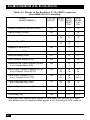
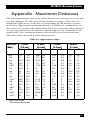
1
MARCH 2004
ME444A-R3
ME444AE-R3
ME444A-530-R3
ME444AE-530-R3
ME445C-35
ME445C-530
ME445C-X.21
256-kbps Line Driver
(V.35, RS-530, or X.21)
CUSTOMER
SUPPORT
INFORMATION
Order toll-free in the U.S.: Call 877-877-BBOX (outside U.S. call 724-746-5500)
FREE technical support 24 hours a day, 7 days a week: Call 724-746-5500 or fax 724-746-0746
Mailing address: Black Box Corporation, 1000 Park Drive, Lawrence, PA 15055-1018
Web site: www.blackbox.com • E-mail: [email protected]
FCC AND IC RFI STATEMENTS
FEDERAL COMMUNICATIONS COMMISSION
AND
INDUSTRY CANADA
RADIO FREQUENCY INTERFERENCE STATEMENTS
This equipment generates, uses, and can radiate radio-frequency energy, and if not
installed and used properly, that is, in strict accordance with the manufacturer’s
instructions, may cause interference to radio communication. It has been tested
and found to comply with the limits for a Class A computing device in accordance
with the specifications in Subpart B of Part 15 of FCC rules, which are designed to
provide reasonable protection against such interference when the equipment is
operated in a commercial environment. Operation of this equipment in a
residential area is likely to cause interference, in which case the user at his own
expense will be required to take whatever measures may be necessary to correct
the interference.
Changes or modifications not expressly approved by the party responsible
for compliance could void the user’s authority to operate the equipment.
This digital apparatus does not exceed the Class A limits for radio noise emission from
digital apparatus set out in the Radio Interference Regulation of Industry Canada.
Le présent appareil numérique n’émet pas de bruits radioélectriques dépassant les limites
applicables aux appareils numériques de la classe A prescrites dans le Règlement sur le
brouillage radioélectrique publié par Industrie Canada.
1
256-KBPS LINE DRIVER (V.35, RS-530, OR X.21)
Safety Warnings
Always observe standard safety precautions during installation,
operation, and maintenance of this product. Only qualified and
authorized service personnel should adjust, maintain, or repair this
instrument. Do not attempt to adjust, maintain, or repair the equipment.
Telecommunication Safety
The safety status of each of the ports on the line driver appears below:
Ports
Safety Status
V.24, V.35, V.36, X.21, RS-530
LAN
SELV
Circuit operating with
Safety Extra-Low Voltage
G.703, Line
TNV-1
Circuit whose normal
operating voltage is
within the limits of SELV,
on which overvoltages
from telecommunications networks are
possible.
FCC Part 15 User Information
This equipment has been tested and found to comply with the limits of a
Class A digital device, pursuant to Part 15 of the FCC rules. These limits
are designed to provide reasonable protection against harmful
interference when the equipment is operated in a commercial
environment. This equipment generates, uses, and can radiate radio
frequency energy, and, if not installed and used in accordance with the
instruction manual, may cause harmful interference to the radio
communications. Operation of this equipment in a residential area is
likely to cause harmful interference in which case the user will be
required to correct the interference at his own expense.
Warning per EN 55022
This is a Class A product. In a domestic environment, this product may
cause interference, in which case the user may be required to take
adequate measures.
2
Declaration of Conformity/Supplementary Information
Declaration of Conformity
The line driver conforms to the following standard(s) or other normative
document(s);
EMC:
Safety:
EN 55022 (1994)
Limits and methods of measurement of radio disturbance
characteristics of information
technology equipment.
EN 50082-1 (1992)
Electromagnetic compatibility—
Generic immunity standards for
residential, commercial, and light
industry.
EN 60950 (1992/3)
Safety of information technology
equipment, including electrical
business equipment.
Supplementary Information
This product complies with the requirements of the EMC Directive
89/336/EEC and the Low Voltage Directive 73/23/EEC. The product was
tested in a typical configuration by the manufacturer.
3
256-KBPS LINE DRIVER (V.35, RS-530, OR X.21)
NORMAS OFICIALES MEXICANAS (NOM)
ELECTRICAL SAFETY STATEMENT
INSTRUCCIONES DE SEGURIDAD
1. Todas las instrucciones de seguridad y operación deberán ser leídas antes de
que el aparato eléctrico sea operado.
2. Las instrucciones de seguridad y operación deberán ser guardadas para
referencia futura.
3. Todas las advertencias en el aparato eléctrico y en sus instrucciones de
operación deben ser respetadas.
4. Todas las instrucciones de operación y uso deben ser seguidas.
5. El aparato eléctrico no deberá ser usado cerca del agua—por ejemplo, cerca
de la tina de baño, lavabo, sótano mojado o cerca de una alberca, etc..
6. El aparato eléctrico debe ser usado únicamente con carritos o pedestales que
sean recomendados por el fabricante.
7. El aparato eléctrico debe ser montado a la pared o al techo sólo como sea
recomendado por el fabricante.
8. Servicio—El usuario no debe intentar dar servicio al equipo eléctrico más allá
a lo descrito en las instrucciones de operación. Todo otro servicio deberá ser
referido a personal de servicio calificado.
9. El aparato eléctrico debe ser situado de tal manera que su posición no
interfiera su uso. La colocación del aparato eléctrico sobre una cama, sofá,
alfombra o superficie similar puede bloquea la ventilación, no se debe colocar
en libreros o gabinetes que impidan el flujo de aire por los orificios de
ventilación.
10. El equipo eléctrico deber ser situado fuera del alcance de fuentes de calor
como radiadores, registros de calor, estufas u otros aparatos (incluyendo
amplificadores) que producen calor.
11. El aparato eléctrico deberá ser connectado a una fuente de poder sólo del
tipo descrito en el instructivo de operación, o como se indique en el aparato.
4
NOM STATEMENT
12. Precaución debe ser tomada de tal manera que la tierra fisica y la polarización
del equipo no sea eliminada.
13. Los cables de la fuente de poder deben ser guiados de tal manera que no
sean pisados ni pellizcados por objetos colocados sobre o contra ellos,
poniendo particular atención a los contactos y receptáculos donde salen del
aparato.
14. El equipo eléctrico debe ser limpiado únicamente de acuerdo a las
recomendaciones del fabricante.
15. En caso de existir, una antena externa deberá ser localizada lejos de las lineas
de energia.
16. El cable de corriente deberá ser desconectado del cuando el equipo no sea
usado por un largo periodo de tiempo.
17. Cuidado debe ser tomado de tal manera que objectos liquidos no sean
derramados sobre la cubierta u orificios de ventilación.
18. Servicio por personal calificado deberá ser provisto cuando:
A: El cable de poder o el contacto ha sido dañado; u
B: Objectos han caído o líquido ha sido derramado dentro del aparato; o
C: El aparato ha sido expuesto a la lluvia; o
D: El aparato parece no operar normalmente o muestra un cambio en su
desempeño; o
E: El aparato ha sido tirado o su cubierta ha sido dañada.
5
256-KBPS LINE DRIVER (V.35, RS-530, OR X.21)
TRADEMARKS USED IN THIS MANUAL
AS/400 and IBM are registered trademarks of International Business
Machines Corporation.
Any other trademarks mentioned in this manual are acknowledged to be the property of the
trademark owners.
6
CONTENTS
Contents
Chapter
Page
1.
Specifications ............................................................................................. 8
2.
Introduction ...............................................................................................10
2.1 Physical Description ............................................................................10
2.2 Functional Description ..................................................................... 11
2.2.1 Encoder Modulator ................................................................. 11
2.2.2 Modulation Timing ................................................................ 12
2.2.3 Signal Levels ........................................................................... 12
2.2.4 Receiver .................................................................................. 12
2.2.5 V.54 Diagnostics ..................................................................... 13
2.2.6 Test-Pattern Generator and Receiver ................................... 13
2.3 Applications ........................................................................................ 13
3.
Configuration...............................................................................................15
3.1 Placement of the Standalone Version .................................................15
3.2 Installing the Card Version in the RackNest 2/14..............................15
3.3 Configuring the Standalone or Card Version.....................................17
4.
Installation....................................................................................................21
4.1 Installing the Standalone Version in 19" Racks ..................................21
4.1.1 Overview .....................................................................................21
4.1.2 Installing a Single Unit in a 19-Inch Rack ................................21
4.1.3 Installing Two Standalone Units in a 19-Inch Rack.................22
4.2 Installing the 256-kbps Rackmount Card Version ..............................24
4.3 Connecting Data Cables .......................................................................33
4.3.1 Power Connection......................................................................33
4.3.2 LINE Connection.......................................................................34
4.3.3 DTE Connection ........................................................................34
5.
Operation ...................................................................................................36
5.1 Controls and Indicators .................................................................... 36
5.2 Operating Procedure ........................................................................ 38
6.
Troubleshooting ........................................................................................39
6.1 Loop Tests ...........................................................................................39
6.2 Bit-Error-Rate Tester (BERT) ..............................................................39
6.3 The Modem Self-Test ........................................................................ 41
6.4 Local Analog Loopback ......................................................................41
6.5 Remote Digital Loopback ...................................................................43
6.6 Local Digital Loopback ......................................................................44
6.7 Calling Black Box .............................................................................. 45
6.8 Shipping and Packaging .................................................................... 46
Appendix: Maximum Distances ...................................................................... 47
7
256-KBPS LINE DRIVER (V.35, RS-530, OR X.21)
1. Specifications
Compliance: FCC Class A, IC Class/classe A
Protocol: Synchronous or asynchronous
Clock Source: Internal, external (from attached device), or receive clock derived
from the receive signal
Flow Control: None
Operation: 4-wire, full- or half-duplex, point-to-point or multipoint
Data Rate: Sync: 19.2, 32, 48, 56, 64, 72, 96, 112, 128, 144, 192, or 256 kbps
(user-selectable); Async: 19.2, 28.8, 38.4, 57.6, or 115.2 kbps (user-selectable)
Maximum Distance: See the tables in the Appendix
User Controls: (4) Front-mounted buttons: (1) DIG, (1) ANA, (1) REM, (1) PATT;
(1) Internal data-rate screwdial; (14) Internal jumpers and (1) internal 3-position
DIP switch for timing, testing, signal levels/impedances, and other features
Diagnostics: V.54-compliant loopback tests; V.52-compliant BERT
Standards: Loopback tests: ITU-TSS V.54; BERT: ITU-TSS V.52
Leads/Signals Supported: See Tables 4-2 through 4-5
MTBF: 75,500 hours
Interfaces: Line side: Proprietary; Device side: ITU-TSS V.35
Connectors: ME444A-R3, ME444AE-R3: (1) 34-pin M-block female, (1) 5-position
terminal block;
ME444A-530-R3, ME444AE-530-R3, ME445C-530, ME445C-35,
ME445C-X21: (1) DB25 female, (1) 5-position terminal block
Indicators: (7) Front-mounted LEDs: PWR (power), RTS, TD, RD, DCD, TEST,
ERR (error)
Temperature Tolerance: 32 to 122°F (0 to 50°C)
Humidity Tolerance: Up to 90% noncondensing
8
CHAPTER 1: Specifications
Maximum Altitude: 8000 ft. (2438.4 m)
Enclosure: High-impact plastic
Power: ME444A-R3: Directly from outlet through detachable 5-ft. (1.5-m) power
cord (included); Optimal input: 115 VAC, 60 Hz; Input ranges: 103.5 to
126.5 VAC, 47 to 63 Hz; Consumption: 5 watts;
ME444AE-R3: Directly from outlet through detachable 5-ft. (1.5-m) power cord;
Optimal input: 230 VAC, 60 Hz; Input ranges: 207 to 253 VAC, 47 to 63 Hz;
Consumption: 5 watts;
ME445C: From the RackNest 2/14; Consumption: 5 watts
Size: ME444A/E-R3: 1.8"H x 7.6"W x 9.6"D (4.6 x 19.3 x 24.4 cm), but the buttons
protrude up to 0.3" (0.8 cm) from the front panel and the connectors protrude
up to 0.8" (2 cm) from the rear panel;
ME445C: 6.2"H x 0.9"W x 9"D (15.7 x 2.3 x 22.9 cm)
Weight: ME444A/E-R3: 3.1 lb. (1.4 kg); ME445C: 0.8 lb. (0.4 kg)
9
256-KBPS LINE DRIVER (V.35, RS-530, OR X.21)
2. Introduction
The 256-kbps Line Driver is a short-range modem for synchronous or
asynchronous transmission—full- or half-duplex—over unconditioned lines. With a
range of up to 11.8 miles (19 km), the line driver operates at user-selectable
synchronous data rates from 19.2 to 256 kbps or asynchronous data rates from
19.2 to 115.2 kbps. The line driver is available in standalone V.35 or RS-530
(ME444A/E-R3) or rackmount card V.35, RS-530, or X.21 (ME445C) versions.
The line driver uses conditional differential diphase modulation (EUROCOM Std.
D1) to provide immunity from background noise, eliminate normal line distortion,
and enable efficient transmission and reception of serial data over twisted-pair
cable. The modem is coupled to the line through isolation transformers which, in
conjunction with protective circuitry, safeguard against AC or DC overvoltages.
With this protective circuitry, the line driver can operate even when DC is
connected to the line.
Transmit timing is provided internally, derived externally from the PC or terminal,
or regenerated from the receive signal. Receive timing is always regenerated from
the receive signal.
The line driver features V.54 diagnostic capabilities for local analog loopback and
local and remote digital loopback testing. In the digital loopback mode, the
operator at either end of the line may test both modems and the line. The
loopback is controlled either by pressing front-panel buttons or by manipulating
signals on the V.35, RS-530, or X.21 (DTE) interface.
The line driver incorporates a built-in Bit Error Rate Tester (BERT). The internal
BERT enables complete testing of both modems and the line without external test
equipment. Pressing the line driver’s front-panel PATT button causes the unit to
generate a pseudo-random test pattern (511-bit, according to ITU-TSS V.52) for
testing end-to-end connectivity. The ERR LED flashes when a bit error occurs.
2.1 Physical Description
The line driver stands alone as a desktop unit, or can be mounted in a 19-inch rack
with optional brackets (see Section 4.1). Also available is a rackmount card version
that installs in the RackNest 2/14 (see Section 4.2). For descriptions of the line
driver’s controls and indicators, see Section 5.1.
10
CHAPTER 2: Introduction
2.2 Functional Description
This section describes the operation of the line driver’s circuit blocks, primarily the
circuits required for correctly configuring the modem (see Figure 2-1 below).
Figure 2-1. Line driver block diagram.
2.2.1 ENCODER MODULATOR
The encoder modulator receives data from the DTE, then modulates the data
using the “conditional diphase modulation” technique. You can configure the
encoder to operate in one of three modes:
• 4-wire full-duplex (point-to-point)
• 4-wire half-duplex (point-to-point)
• 4-wire multipoint
The appropriate mode is determined by the setting of two jumpers: CARRIER (J2)
and RTS-CTS DLY (J4). For multipoint applications, two additional jumpers must
be set: XMT IMP (J13) and RCV IMP (J10). See Section 3.3 for a more detailed
explanation of the correct jumper settings.
11
256-KBPS LINE DRIVER (V.35, RS-530, OR X.21)
NOTE
In multipoint applications, do not use the 0-msec option for the
RTS–CTS delay.
2.2.2 MODULATION TIMING
This circuit supplies the transmit clock to the encoder. Three clock sources are
available on the XMT CLK jumper (J3):
• INT—Internal clock. From the modem’s internal crystal oscillator.
• EXT—External clock. From DTE.
• RCV—Receive clock. Recovered from the receive signal.
There is also an ASY (asynchronous) setting, but this has no function and should
not be selected.
2.2.3 SIGNAL LEVELS
Two options are available for the transmit and receive signal levels: 0 and -6 dBm.
You can control the transmit level with the XMT LVL jumper. You can control the
receive level with the RCV LVL jumper.
2.2.4 RECEIVER
The receiver comprises several circuits, as shown in the block diagram (see
Figure 2-1):
• The RECEIVE FILTER, which removes all the out-band frequencies.
• The EQUALIZER, which comprises several equalizers activated according to
data rate.
• The digital Automatic Gain Control (AGC), which automatically compensates
for the attenuation of the line.
12
CHAPTER 2: Introduction
2.2.5 V.54 DIAGNOSTICS
V.54 loops are activated manually with the front-panel buttons, or through the
DTE interface. The buttons and the DTE interface can be enabled or disabled
separately by jumpers J7 and J8 (shown in Figure 3-1 and described in Table 3-1).
When you use the line driver as a tail-end to a digital network, the V.54 DLY
jumper in the modems located close to the network should be set to ON to prevent
multiple loopbacks. The delay switch is used to prevent the last modem from
receiving the complete V.54 data sequence and, in turn, being induced into a loop.
2.2.6 TEST-PATTERN GENERATOR AND RECEIVER
This feature allows for easy and quick testing of the local modem as well as the
communication link. When the PATT button on the front panel is pressed, the
circuit sends and checks a standard 511-bit pseudo-random pattern. If the modem
encounters errors, the ERR LED remains ON or blinks.
The test can be carried out in local analog loopback, in remote digital loopback, or
in normal point-to-point operation opposite a remote line driver modem. Press the
PATT pushbutton on the remote unit or connect a Bit Error Rate Tester that uses
the standard 511-bit pattern.
2.3 Applications
The diagrams on this page and the following pages illustrate the line driver
operating in various applications.
4-wire
Up to 11.8 mi. (19 km)
256-kbps
Line Driver
256-kbps
Line Driver
19.2 to
256 kbps
AS/400
AS/400®
Figure 2-2. Point-to-point application.
13
256-KBPS LINE DRIVER (V.35, RS-530, OR X.21)
4-wire
twisted pair
DDS
(56 kbps)
CSU/DSU
External
clock
CSU/DSU
Sync host
256-kbps
Line Driver
Receive
clock
256-kbps
Line Driver
Sync host
Tail circuit
Figure 2-3. Tail-circuit application.
V.35 interface
V.35 interface
V.35
cable
4-wire
twisted pair
(64 kbps)
V.35
cable
256-kbps
Line Driver
IBM® S/3X
mainframe
V.35 interface
IBM 3274
controller
V.35
cable
256-kbps
Line Driver
V.35 interface
IBM 3274
controller
V.35
cable
256-kbps
Line Driver
IBM 3274
controller
Figure 2-4. Multipoint application.
14
CHAPTER 3: Configuration
3. Configuration
This chapter explains how to configure your standalone or rackmount card line
driver. After you configure it, see Chapter 4 for how to install it, Chapter 5 for how
to operate it, and Chapter 6 for how to test the system.
3.1 Placement of the Standalone Version
Place the 256-kbps Line Driver standalone model within 5 ft. (1.5 m) of a
grounded, easily accessible AC outlet. The outlet should be capable of providing
either 115 VAC (for the ME444A-R3 model) or 230 VAC (for the ME444AE-R3
model).
The line driver is designed to be placed on a tabletop or bench, and is shipped
completely assembled. Allow at least 36" (91.4 cm) of frontal clearance for
operation and access for maintenance. You also need at least 4" (10.2 cm) of
clearance at the rear of the unit for signal lines and interface cables.
3.2 Installing the Card Version in the RackNest 2/14
The RackNest 2/14 is a special 19" rack component designed to host a number of
our short-haul modems and line drivers. It consists of a rack chassis (with one or
two power supplies) into which you can plug as many as 14 modem or driver cards.
The nest’s rear panel consists of fourteen five-screw terminal blocks (“TB1”) and
fourteen connectors (“J1”). Each terminal block (“TB1”) provides four screws for
connecting nest-to-nest G.703 transmit and receive lines—the transmit pair can be
connected to the terminals marked XMT, and the receive pair can be connected to
the terminals marked RCV—plus a fifth screw for ground connection.
Each interface connector (“J1”) is a DB25 female. The pinning of this connector
depends on the type of card installed in the corresponding slot, because the cards
will present and expect different signals on different pins. For the V.35 model of
the line driver card (ME445C-35), the pinning is a special V.35-on-DB25 variant;
for the RS-530 and X.21 models, the pinning is RS-530. Refer to Tables 4-2 through
4-5 (Chapter 4) for the pinouts of this connector, and for the pinning of the
adapters or adapter cables that will be necessary to attach a V.35 or X.21 DTE to
this connector.
15
256-KBPS LINE DRIVER (V.35, RS-530, OR X.21)
DESCRIPTION OF THE RACKNEST 2/14’S POWER SUPPLY
The 115-VAC RackNest 2/14 (our product code RM110A) uses the PS1000A power
supply, which accepts 115-VAC input power. The 230-VAC RackNest 2/14 uses
power supply PS1000AE, which accepts 230-VAC input power. Each of these power
supplies consists of a power-line transformer and a fuse. The 115-VAC nest can also
be ordered with dual power supplies (our product code RM110A-2PS); either of
these power supplies can be hot-swapped if it fails.
All power-regulating circuitry for the RackNest 2/14 is located on the card
modems themselves. Each card has two fuses which protect the entire system
against power failure due to a short circuit in one card. Primary power needed is
115 or 230 VAC ±10%, 47 to 63 Hz, at 24 VA maximum.
AC power should be supplied to the RackNest 2/14 through a standard power
cable run between the AC mains socket on the rear of the nest’s power-supply
module—an IEC 320 male power inlet which contains an integral fuse—and a
standard, grounded, easily accessible AC outlet. (If your nest is an RM110A, you
can use the power cord supplied with it; if your nest is an RM110AE, use a power
cord appropriate for your site’s mains outlets.)
The nest begins operating and supplying power to the installed cards as soon as it
is plugged into a mains outlet, and will continue operating until it is unplugged.
WARNING!
This unit should always be grounded through the protective earth lead
of the power cable. Before AC power is connected to this unit, the mains
plug should only be inserted into a socket outlet provided with
protective earth contact. The protective action must not be negated by
use of an extension cord without a grounding conductor.
Whenever it is likely that the unit’s fuse (located in a bayonet-type fuse
holder on the unit’s rear panel) has been blown or damaged, make the
unit inoperative and secure it against unintended operation until the
fuse can be replaced. Make sure that only fuses of the required rating,
as marked on the rear panel, are used for replacement. Do not use
repaired fuses or short-circuit the fuse holder. Always disconnect the
mains cable before removing or replacing the fuse.
Interrupting the grounding conductor, inside or outside the unit, or
disconnecting the protective earth contact, can make this unit
dangerous!
16
CHAPTER 3: Configuration
3.3 Configuring the Standalone or Card Version
Before attaching anything to the 256-kbps Line Driver standalone or rackmount
card version, determine which data rate you’re going to use, what the system’s
clock source should be, and how you want to set all of the other user-configurable
options on the line driver. (Refer to Table 3-1 on the next two pages for a list of all
of these options; the SWn and Jn numbers in the table’s “Element” column
correspond to the locations with the same numbers in Figure 3-1.)
Table 3-1. User-configurable options.
Element
Function
Possible
Settings
SW3
BAUD RATE
dial
Select the data rate in kilobits per second.
J1
V54 DIS
jumper
Enable or disable requests for V.54 digital
loopback tests from the remote line driver.
J2
CARRIER
jumper
Select the transmit-carrier mode. When you
set this jumper to “ON,” transmit carrier is
constantly ON. When you set this jumper to
jumper to “CNTRL,” transmit carrier is ON only
when RTS is high.
Use the CNTRL setting for multipoint
applications.
CNTRL
ON
J3
XMT CLK
jumper
Select the source of the transmit timing signal:
internal clock, external clock (from DTE), or
receive clock (from remote unit). Do not select
the ASY (asynchronous, no clock) setting.
INT
EXT
RCV
ASY
SW2
Data-format
DIP switch
(This switch only comes into play when ASY
[asynchronous] is selected on jumper J3. ASY
should never be selected on this unit, so the
settings of this switch are irrelevant.)
Standard
Factory
Setting
Opt. 1
0-256
1-192
2-144
3-128
4-115.2*
5-112
6-96
7-72
8-64
64 kbps
9-57.6*
A-56
B-48
C-38.4*
D-32
E-28.8
F-19.2*
*Async/
sync baud
rate
DIS
EN
EN (enabled)
ON
INT (Internal)
17
256-KBPS LINE DRIVER (V.35, RS-530, OR X.21)
Table 3-1 (continued). User-configurable options.
Element
Function
Possible
Settings
Standard
Factory
Setting
J4
RTS-CTS
DLY jumper
Select the delay in milliseconds that
occurs during RTS-to-CTS transitions.
Do not select 0 for multipoint applications.
0
9
70
J5
V54 DLY
jumper
Turn V.54 delay ON or OFF. When you turn
it ON, V.54 delay prevents multiple loopback
of tail-end circuits.
ON
OFF
J6
SW. EN.
jumper
Enable or disable the DIG, ANA, and REM
loopback-control buttons on the unit’s front
panel.
ON
OFF
ON (enabled)
J7
RLB DTE**
jumper
Enable or disable electronic control of
remote digital loopback testing through the
DTE interface.
EN
DIS
EN (enabled)
J8
ALB DTE**
jumper
Enable or disable electronic control of
local analog loopback testing through the
DTE interface.
EN
DIS
EN (enabled)
J9
RCV LVL
jumper
Select the level (in dBm) of receive
input from the line.
-6
0
J10
RCV IMP
jumper
Select the receive-line impedance. In
multipoint applications, it is advisable to
set the master modem and the last modem
in the line to 150 Ω, and all others to HIGH.
150 [Ω]
HIGH
150 ohms
J11
RPF.
jumper
Enable or disable the remote power
failure feature.
ON
OFF
ON
J12
XMT LVL
jumper
Select the level (in dBm) of transmit
output to the line.
-6
0
J13
XMT IMP
jumper
Select the transmit-line impedance in
ohms. In multipoint applications, it is a
good idea to set the master modem to
“LOW.”
150 [Ω]
LOW
J14
CHASS
jumper
Set to CON to connect signal ground to
chassis ground. Set to DIS to keep the
two grounds isolated from each other.
DIS
CON
**NOTES:
18
9 ms
OFF
0 dBm
0 dBm
150 ohms
CON (connected)
If the DTE does not provide the test pins for analog and remote loopback, the ALB DTE
and RLB DTE jumpers must be always set to DIS.
CHAPTER 3: Configuration
Figure 3-1. Layout of the 256-kbps Line Driver circuit board.
19
256-KBPS LINE DRIVER (V.35, RS-530, OR X.21)
When you have everything at least tentatively decided, take these steps to set the
unit’s internal controls.
CAUTION!
Disconnect the standalone line driver from the power line before
removing it from its housing.
WARNING: HIGH VOLTAGE!
Any adjustment, maintenance, and repair of the open instrument under
voltage should be avoided as much as possible, and, when inevitable,
should be carried out only by a skilled person who is aware of the
hazard involved. Capacitors inside the instrument may still be charged
even after the instrument has been disconnected from the power
source.
1. Disconnect the AC power cord from the AC mains outlet.
2. Unscrew the two rear-panel screws until the rear panel becomes loose. This
releases the unit’s “drawer” mechanism; now you can pull the screws as if they
were the knobs on a drawer and expose or remove the unit’s circuit board.
3. Identify the control(s) (refer to Figure 3-1).
4. Move the control(s) to your desired position(s).
5. Replace the circuit board and screw the rear-panel screws back in.
20
CHAPTER 4: Installation
4. Installation
4.1 Installing the Standalone Version in 19-Inch Racks
4.1.1 OVERVIEW
The 256-kbps Line Driver standalone version can be installed in 19-inch racks. It is
1U (1.75", 4.4 cm) high and is slightly less than half as wide as the available
mounting area.
Two rack-adapter kits are available as special quotes: One kit provides the
hardware necessary to install a single unit, and the other provides the hardware
necessary to install two units side by side. Sections 4.1.2 and 4.1.3 provide step-bystep instructions for installation of single or dual units.
CAUTION!
Disconnect the units from AC power while performing the following
procedures.
4.1.2 INSTALLING A SINGLE UNIT IN A 19-INCH RACK
The rack-adapter kit for single-unit installation includes one short bracket and one
long bracket. The brackets are fastened with screws to the two side walls of the
case, as shown in Figure 4-1.
To prepare the standalone line driver for rack installation, attach the two brackets
to the sides of the unit. Do this by inserting screws and flat washers into the two
holes at the front of each side of the line driver (nuts are already in place inside
the unit).
After attaching the brackets, install the unit in your 19-inch rack by fastening the
brackets to the rack’s side rails with four screws (not included in the kit), two on
each side.
21
256-KBPS LINE DRIVER (V.35, RS-530, OR X.21)
Figure 4-1. Installing a single unit in a 19-inch rack.
4.1.3 INSTALLING TWO STANDALONE UNITS IN A 19-INCH RACK
The adapter kit includes two long side rails (one for each unit), which slide into
each other to fasten the units together, and two short side brackets, which hold the
two line drivers side by side in a 19-inch rack. Refer to Figure 4-2 when you
perform the following procedure:
1. Fasten one long side rail to each standalone line driver—one rail on the right
side of one unit, the other rail on the left side of the other unit—using the
four included screws and flat washers. The rails must be attached so that they
“oppose” each other: The narrow flange of the first rail must face the wide
flange of the second rail.
2. Using four included screws and flatwashers for each bracket, attach the two
short brackets to the vacant sides of the standalone line drivers.
3. Slide the two line drivers’ side rails into each other, fastening the two units
together.
22
CHAPTER 4: Installation
4. Secure the included plastic caps to the ends of the rails, to protect the rail
ends and prevent the units from moving.
5. You can now use four screws (not supplied with the kit), two on each side, to
fasten the assembled units to the side rails of the 19-inch rack.
Figure 4-2. Installing two units in a 19-inch rack.
23
256-KBPS LINE DRIVER (V.35, RS-530, OR X.21)
4.2 Installing the 256-kbps Line Driver Rackmount Card Version
THE RACKNEST 2/14 ILLUSTRATED
You will be installing the line driver card in the RackNest 2/14 as shown
in Figure 4-3. The front and rear panels of the RackNest are shown
in Figure 4-4; the numbered connectors, controls, and indicators
are described in Table 4-1.
Figure 4-3. Installing a card in the RackNest 2/14.
24
CHAPTER 4: Installation
ON
2
1
3
4
6
GND
RCV
XMIT
5
7
Figure 4-4. The RackNest 2/14 illustrated.
25
256-KBPS LINE DRIVER (V.35, RS-530, OR X.21)
Table 4-1. Descriptions of RackNest 2/14 components.
Item
Control, Indicator, or Connector
1
Card Slots
Slots for installation of compatible cards
(slot no. 1 located at the left-hand side).
Unused slots are closed with blank
panels.
2
Power-Supply Module
Provides power to modules installed in
the enclosure.
3
ON Indicator
Lights when power supply is operating.
4
Chassis-Ground Terminal
Connector for attaching other grounds,
devices, etc., to the RackNest’s chassis
ground (optional).
5
Power Connector
Power connector with integral fuse.
6
Main Channel Connectors (J1)
DB25 connectors for the module DTE
connection.
7
4-Wire Terminal Blocks (TB1)
For connection of 4-wire lines. Each
modem card has a separate terminalblock connector.
26
Function
CHAPTER 4: Installation
After you install the RackNest 2/14 in your 19" rack (refer to the RackNest’s
manual), take these steps to install a line driver card in the RackNest:
1. Insert the card into an empty slot on the RackNest (see Figure 4-3). Do
not use excessive force. If the card does not go in easily, remove the card,
realign it with the RackNest’s enclosure guides, and push it into place.
NOTE
When the RackNest 2/14 is ON, personnel are not exposed to any voltage
over 30V on any card or accessible area of the nest. Still, take all
reasonable precautions to avoid electric shock.
2. Tighten the nut on the top of the card.
3. Push the bottom of the card as far into the RackNest as it will
comfortably go, to ensure that its card-edge connector makes full contact
with the RackNest’s.
4. Run an appropriate cable from your DTE to the corresponding DB25
connector (“J1”) on the back of the RackNest:
• ME445C-530 (RS-530) units: You can use standard RS-530 (DB25 maleto-male) cable. Refer to Table 4-2 for more information.
• ME445C-35 (V.35) units: Either this cable needs to be specially pinned
(see Table 4-3) and have a DB25 male connector at the RackNest end
and an M/34 male connector at the DTE end, or you need to use a
correctly pinned, short DB25-male-to-M/34-female cable or similar
adapter to patch between the V.35 (M/34 male-to-male) cable and the
RackNest’s DB25 connector. Call Black Box for a quote on this type of
cable.
• ME445C-X21 (X.21) units: Either this cable needs to be pinned for
RS-530 to X.21 (see Table 4-5) and have a DB25 male connector
at the RackNest end and a DA15 (“DB15”) male connector at the DTE
end, or you need to use a correctly pinned, short DB25-male-to-DA15female cable or similar adapter to patch between the X.21 (DA15
male-to-male) cable and the RackNest’s DB25 connector. Call Black
Box for a quote on this type of cable.
5. If you haven’t already done so, install the remote RackNest 2/14. Repeat
steps 1 through 4 at the remote site.
27
256-KBPS LINE DRIVER (V.35, RS-530, OR X.21)
6. Run twisted-pair cable between the local and remote cards. Attach one
pair of wires to the corresponding XMT terminals (“TB1”) on the back of
the local RackNest and the corresponding RCV terminals on the remote
RackNest; attach the other pair of wires to the RCV terminals on the local
RackNest and the XMT terminals on the remote RackNest. (It doesn’t
matter which wire in each pair goes to which terminal in each pair; the
cards autosense parity.) If you’re using a ground wire, attach it to the GND
terminal on one RackNest (not both of them!)
28
CHAPTER 4: Installation
Table 4-2. Pinout of the RackNest 2/14’s DB25 connector when
ME445C-530 is installed or RS-530 standalone’s DB25 connector.
SIGNAL
NAME (ABBREV.)
ITU-TSS
CIRCUIT
LEAD
TYPE
DB25
PIN
Shield (SHD)
101
1
Signal Ground (SGND)
102
7
Transmitted Data (TD)
103
A
B
2
14
Received Data (RD)
104
A
B
3
16
Request to Send (RTS)
105
A
B
4
19
Clear to Send (CTS)
106
A
B
5
13
DCE Ready (DCR)
a.k.a. Data Set Ready (DSR)
107
A
B
6
22
Data Terminal Ready (DTR)
108
A
B
20
23
Received Line Signal Detector (RLSD),
a.k.a. Carrier Detect (CD)
109
A
B
8
10
Transmitter Sig. Elem. Timing (DTE Source)
(TSETT), a.k.a. External Clock (EXTC)
113
A
B
24
11
Transmitter Sig. Elem. Timing (DCE Source)
(TSETC), a.k.a. Transmit Clock (TC)
114
A
B
15
12
Receiver Sig. Elem. Timing (DCE Source)
(RSETC), a.k.a. Receive Clock (RC)
115
A
B
23
22
Remote Loopback (RL)
140
21
Local Loopback (LL)
141
18
Test Mode (TM)
142
25
29
256-KBPS LINE DRIVER (V.35, RS-530, OR X.21)
Table 4-3. Pinout of the RackNest 2/14’s DB25 connector
when ME445C-35 is installed.
SIGNAL
NAME (ABBREV.)
ITU-TSS
CIRCUIT
LEAD DB25
M/34
TYPE (RACK- (NORM.
NEST)
V.35)
PIN
PIN
Frame (Protective) Ground (FGND)
101
1
A
Signal Ground (SGND)
102
7
B
Send Data (SD)
103
A
B
9
11
P
S
Receive Data (RD)
104
A
B
12
13
R
T
Request to Send (RTS)
105
4
C
Clear to Send (CTS)
106
5
D
Data Set Ready (DSR)
107
6
E
Data Terminal Ready (DTR)
108
20
H
Received Line Signal Detector (RLSD),
a.k.a. Carrier Detect (CD)
109
8
F
Serial Clock Transmit External (SCTE),
a.k.a. External Clock (EXTC)
113
A
B
19
16
U
W
Serial Clock Transmit (SCT),
a.k.a. Transmit Clock (TC)
114
A
B
14
10
Y
AA, a
Serial Clock Receive (SCR),
a.k.a. Receive Clock (RC)
115
A
B
23
22
V
X
Remote Digital Loopback (RL)
140
21
HH, h*
Local Analog Loopback (LL)
141
18
JJ, j*
Test Mode (TM)
142
25
KK, k*
*Black Box often assigns these signals to these M/34 pins, but your DTE might
use different pins (if it supports these signals at all). Consult your DTE’s manual.
30
CHAPTER 4: Installation
Table 4-4. Pinout of the V.35 standalone’s M/34 connector.
SIGNAL
NAME (ABBREV.)
ITU-TSS
CIRCUIT
LEAD
TYPE
V.35
PIN
Frame (Protective) Ground (FGND)
101
A
Signal Ground (SGND)
102
B
Send Data (SD)
103
A
B
P
S
Receive Data (RD)
104
A
B
R
T
Request to Send (RTS)
105
C
Clear to Send (CTS)
106
D
Data Set Ready (DSR)
107
E
Data Terminal Ready (DTR)
108
H
Received Line Signal Detector (RLSD),
a.k.a. Carrier Detect (CD)
109
F
Serial Clock Transmit External (SCTE),
a.k.a. External Clock (EXTC)
113
A
B
U
W
Serial Clock Transmit (SCT),
a.k.a. Transmit Clock (TC)
114
A
B
Y
AA
Serial Clock Receive (SCR),
a.k.a. Receive Clock (RC)
115
A
B
V
X
Remote Digital Loopback (RL)
140
HH
Local Analog Loopback (LL)
141
JJ
Test Mode (TM)
142
KK
31
256-KBPS LINE DRIVER (V.35, RS-530, OR X.21)
Table 4-5. Pinout of the RackNest 2/14’s DB25 connector when
ME445C-X21 is installed.
SIGNAL
NAME (ABBREV.)
ITU-TSS
CIRCUIT
LEAD DB25
DA15
TYPE (RACK- (NORM.
NEST)
X.21)
PIN*
PIN
Shield (n/a)
101
1
1
Ground (G)
a.k.a. Signal Ground (SGND)
102
7
8
Transmit (T)
103
A
B
2
14
2
9
Receive (R)
104
A
B
3
16
4
11
Control (C)
a.k.a. Request to Send (RTS)
105
A
B
4
19
3
10
Indication (I)
a.k.a. Carrier Detect (CD)
109
A
8
10
5
12
RS-530: Transmitter Signal Element
Timing (DTE Source) (TSETT)†
113
A
B
24
11
7†
14†
Signal Timing (S)
114
A
B
15
12
6
13
*This pinout follows the TIA RS-530 standard.
†Standard X.21 does not support an external clock, and specifies that DA15 Pins 7
and 14 should be used for the Byte Timing (B) A and B signals. Because Byte
Timing is hardly ever used, but an external clock is often necessary for today’s
data communication, many Black Box devices are designed to this modified
specification in which the RS-530 external-clock signal replaces Byte Timing.
32
CHAPTER 4: Installation
4.3 Connecting Data Cables
After you set the standalone line driver’s internal controls, it’s ready to be cabled
for operation.
Its electrical connectors are located on its rear panel. These consist of a female
V.35 interface connector labeled “DTE,” a 5-screw terminal block, and an IEC 320
AC inlet that contains an integral fuse compartment.
The V.35 interface connector, a 34-pin M-block female, carries input/output data,
clock signals, and control signals between the line driver and the DTE or DCE
(refer to Table 4-4).
The terminal block has five screws for connecting transmit and receive lines—the
transmit pair where XMT is indicated (for data output from the unit), the receive
pair where RCV is indicated (for data input to the unit), and a drain wire from the
cable shield, if you are using shielded cable, where GND is indicated. The XMT
and RCV pairs are not sensitive to polarity.
Connect power and data cables to the line driver as described in the following
subsections.
4.3.1 POWER CONNECTION
The power connection provides AC voltage to the line driver.
To make this connection on the 115-VAC (ME444A-R3) models, first attach the
IEC 320 female outlet of the included power cord to the IEC 320 male inlet on the
standalone line driver’s rear panel.
To make this connection on the 230-VAC (ME444AE-R3) models, first attach the
IEC 320 female outlet of an appropriate power cord to the IEC 320 male inlet on
the standalone line driver’s rear panel. (This power cord must have a plug on the
other end that will fit the site’s mains outlets.)
WARNING!
BEFORE PLUGGING THIS UNIT INTO AN OUTLET OR OTHER LIVE
POWER SOURCE, make sure its protective earth contact is connected to
the protective conductor of the (mains) power cord. The mains plug
must be inserted only in a socket outlet provided with a protective earth
contact. The protective action must not be negated by use of an
extension cord (power cable) without a protective (grounding)
conductor.
If the line driver’s fuse blows (opens), make sure that you replace it only with a
33
256-KBPS LINE DRIVER (V.35, RS-530, OR X.21)
fuse rated for the required amount of current. You must avoid using repaired fuses
or short-circuiting the fuse holders. The fuse, and one replacement fuse, are
located in the top part of the mains connector on the line driver’s rear panel. The
nominal current value of the fuse is 0.125 A for 230-VAC operation or 0.25 A for
115-VAC operation.
Whenever it is likely that the protection offered by the fuse has been impaired, the
unit must be made inoperative and secured against any unintended operation.
After you have attached the power cord and have made sure that the cord is
properly grounded, you can plug the power cord into a working mains outlet.
CAUTION!
The unit has no power switch. It starts operating as soon as power
of the proper type is applied to its POWER connector.
4.3.2 LINE CONNECTION
The LINE connection provides an interface for the TX and RX signals between
pairs of line drivers. To make this connection, attach the line wires to the terminal
block on the line driver this way:
• XMT + (remote line driver) to RCV + (local unit);
• XMT – (remote unit) to RCV – (local unit);
• RCV + (remote unit) to XMT + (local unit);
• RCV – (remote unit) to XMT – (local unit);
• Optional: Shield or drain wire (line cable) to ground (local line driver—the
rightmost terminal).
All connections are made on the back of the line driver.
4.3.3 DTE CONNECTION
The interface (DTE) connector provides an interface for input/output data, as
well as clock and control signals, between the line driver and a V.35 DTE or DCE.
This connector is a standard 34-pin M-block (“M/34”) female. The pinout of this
connector is shown in Table 4-4.
34
CHAPTER 4: Installation
To connect the line driver to a V.35 DTE or DCE, use an appropriate cable that is
pinned correctly (straight-through for DTE, properly crossed for DCE). Run this
cable from the other device to the line driver and attach it to the line driver’s
interface connector.
Your line driver should now be ready for continuous operation.
35
256-KBPS LINE DRIVER (V.35, RS-530, OR X.21)
5. Operation
This chapter contains a list of the controls and indicators and their functions, as
well as a brief description of how to operate the unit. Installation procedures must
be completed and checked before you attempt to operate the line driver.
5.1 Controls and Indicators
The front panel of the standalone line driver is shown in Figure 5-1 below. The
front panel of the rackmount card line driver is shown in Figure 5-2. It contains all
of the unit’s external controls and indicators. The functions of the controls are
described in Table 5-1, and the meanings of the indicators are described in Table
5-2. In each of these tables, the letters and numbers under the heading “Item”
correspond to the letters and numbers in Figure 5-1 or 5-2.
PWR RTS
1
2
TD
RD
3
4
DIG
ANA
REM
PATT
A
B
C
D
DCD TEST ERR
5
6
7
Figure 5-1. The front panel of the standalone line driver.
36
CHAPTER 5: Operation
PWR
2
1
RTS
TD
4
3
RD
5
DCD
6
TEST ERR
7
RPF
E
DIG
A
ANA
B
REM
C
PATT
D
Figure 5-2. The front panel of the rackmount card line driver.
Table 5-1. The controls.
The Item labels in this table correspond to those in Figures 5-1 and 5-2.
ITEM
CONTROL
FUNCTION
A
DIG
Pressing the local digital loopback button causes the local LDM-MR256 to
loop received data and clock to its transmitter. Data Set Ready goes low.
B
ANA
Pressing the local analog loopback (V.54 Loop 3) button causes the local
LDM-MR256 to loop its transmitter output back to its receiver. This
loopback may also be activated from the DTE when the “ALB DTE” jumper
is set to EN.
C
REM
Pressing the remote digital loopback (V.54 Loop 2) switch causes the
remote LDM-MR256 to loop received data and clock to its transmitter.
Data Set Ready goes low. This loopback may be also activated from the
DTE when the “RLB DTE” strap is set to EN.
D
PATT
E
RPF
Pressing the PATT button causes the LDM-MR256 to send and receive a
511 test pattern. If errors are encountered, the ERR LED becomes
steadily lit or blinks. Receive Data and Clear to Send go low. Note: The
unit’s “CARRIER” jumper should be set to ON; if it is set to CNTRL, the
RTS signal must be high.
Remote Power Failure resets the ERR/RPF LED.
37
256-KBPS LINE DRIVER (V.35, RS-530, OR X.21)
Table 5-2. The indicators.
The item numbers in this table correspond to Figures 5-1 and 5-2.
ITEM
INDICATOR
FUNCTION
1
PWR
Green LED is on when power is on.
2
RTS
Yellow LED is on when terminal activates Request to Send.
3
TD
Yellow LED is on when steady SPACE is being transmitted. It flickers
when data is transmitted.
4
RD
Yellow LED is on when steady SPACE is being received. It flickers
when data is received.
5
DCD
Yellow LED is on when a valid receive signal is present.
6
TEST
Red LED is on when the LMD-MR256 is in any of the loopback modes.
7
ERR
LED goes ON when PATT switch is activated and then dims. If there are
errors in the test pattern, the LED blinks or remains ON.
5.2 Operating Procedure
The line driver operates entirely unattended, although we recommend that you
monitor its LEDs occasionally. To turn the unit off, you must unplug its power
cord from the outlet—it has no power switch.
If you want to reconfigure the line driver for a different type of operation, make
very sure to unplug the unit first. After the unit is powered down, change the
settings of its internal controls as necessary, following the instructions in
Section 3.3.
38
CHAPTER 6: Troubleshooting
6. Troubleshooting
This chapter explains system-test and fault-isolation procedures.
The line driver provides local loopback and remote digital loopback in compliance
with the V.54 standard. Unless you disable them, the unit’s loopback tests can be
activated manually from the unit’s front panel, and the local analog and remote
digital loopbacks can be activated electronically through the DTE connection.
6.1 Loop Tests
The loop-test buttons (DIG, ANA, and REM) and LEDs built into the line driver
allow you to rapidly check the unit, the attached cables, and the attached DTEs.
Use the test procedures described in this chapter to verify normal system operation
and to isolate faulty equipment if a failure occurs. (Before testing the operation of
the system equipment and line circuits, make sure that all devices are turned on
and are properly configured.)
6.2 The Bit-Error-Rate Tester (BERT)
You can activate the line driver’s internal Bit Error Rate Tester in any diagnostics
test in which the transmitted test pattern is looped back to the BERT for
comparison. An example is shown in Figure 6-1 on the next page.
The line driver is also capable of operating opposite any 511 BERT tester. When
you use one line driver opposite another, either with one or both PATT buttons
pressed (see Figure 6-2) or with an external BERT transmitting the same V.52 (511bit) pattern, you can test the complete link. To activate the BERT, press the PATT
button. The ERR LED will light momentarily, just to confirm that the LED is
working, and then the test will proceed. If errors are detected, the ERR LED will be
continuously lit (if the errors are continuous) or will blink (for intermittent
errors).
NOTE
For the line driver’s BERT to operate correctly, the CARRIER jumper
must be set to ON or the RTS signal must be high.
While PATT is pressed, the V.35 interface is functionally disconnected.
39
256-KBPS LINE DRIVER (V.35, RS-530, OR X.21)
PATT
PRESSED
PATTERN
GENERATOR
PATTERN
TESTER
XMT
RCV
ERROR
ASM-20
Figure 6-1. BERT using loops.
PATT
DEPRESSED
DEPRESSED
(DISCONNECTS
EXTERNAL DTE)
RCV
PATTERN
GENERATOR
PATTERN
TESTER
ERROR
PATTERN
TESTER
PATTERN
GENERATOR
DTE
XMT
ERROR
Figure 6-2. Two line drivers doing end-to-end BERT.
40
CHAPTER 6: Troubleshooting
6.3 The Modem Self-Test
To verify that the line driver itself is operating correctly, initiate the modem selftest by pressing the PATT and ANA buttons (refer to Figure 6-3 below):
1. Press ANA to start local analog loopback. Both the TEST and DCD LEDs
should light. If the DCD LED doesn’t light, make sure that the RTS signal is
not OFF (low) while the CARRIER jumper is OFF.
2. Press PATT to begin test-pattern transmission. Verify that the TEST and DCD
LEDs are still lit and that the ERR LED lights briefly.
3. If the ERR stays lit or continues to flicker after the initial flash, the line driver
is faulty; call Black Box to arrange for repair or replacement. Otherwise, the
unit passes the test; restore all of the buttons to their normal positions.
PATT
DEPRESSED
ANA
DEPRESSED
PATTERN
GENERATOR
XMTR
PATTERN
TESTER
RCVR
ERROR
Figure 6-3. Modem self-test.
6.4 Local Analog Loopback
Activate the local analog loopback test by pressing the ANA button or by raising
the level of the Local Loopback signal received by the line driver’s V.35 connector
(Pin JJ). This test checks the performance of the local line driver, the local DTE,
and the connections between them. Perform this test separately at the local and
remote sites (refer to Figure 6-4 on the next page):
1. Press ANA or raise Local Loopback to start local analog loopback. The
TEST LED should light. The line driver’s G.703 transmit output should be
connected to its own receiver.
41
256-KBPS LINE DRIVER (V.35, RS-530, OR X.21)
2. Verify that the DTE is operating properly and can be used for a test.
3. Perform the test using one of these methods:
• Send data from the DTE and check the echoed data stream.
• Hook up an external Bit Error Rate Test (BERT) unit in place of the DTE.
• Use the line driver’s internal BERT. Press the PATT button.The ERR LED
should light briefly just to confirm that the LED is working, and then the test
will proceed. If errors are detected, the ERR LED will be continuously lit (if
the errors are continuous) or will blink (for intermittent errors).
4. Repeat Steps 1 through 3 at the remote site.
5. If the BERT tests show no errors, but the data echoed back to either DTE is
bad, check the DTE and the cable connecting it to the line driver—one of
them is faulty.
6. After the test is complete or the fault has been corrected, restore the ANA
button to its normal position. Proceed with the digital loopback tests.
ANA
DEPRESSED
DATA
CLK
XMTR
DTE
LINE
CLK
DATA
RCVR
Figure 6-4. Local analog loopback.
42
CHAPTER 6: Troubleshooting
6.5 Remote Digital Loopback
Activate the remote digital loopback test by pressing the REM button or by raising
the level of the remote loopback signal received by the line driver’s V.35 connector
(Pin HH). This test involves creating an outbound loopback at the remote line
driver (see Figure 6-5 on the next page). The test checks the performance of the
local and remote units and the line between them:
1. Press REM or raise remote loopback; the local line driver will signal the
remote unit to start remote digital loopback. The TEST LED should light on
both units. The remote line driver’s receive input should be connected to its
own transmitter.
2. Perform a Bit Error Rate Test (BERT). Either:
• Hook up an external Bit Error Rate Test (BERT) unit in place of the local
DTE; or
• Use the local line driver’s internal BERT. Press the PATT button. The ERR
LED should light briefly just to confirm that the LED is working, and then the
test will proceed. If errors are detected, the ERR LED will be continuously lit
(if the errors are continuous) or will blink (for intermittent errors).
3. If the BERT test indicates a fault, but both line drivers pass their modem selftests, there is a problem somewhere in the communication line between the
units.
4. After the test is complete or the fault has been corrected, restore the REM
button to its normal position. Proceed with local digital loopback.
43
256-KBPS LINE DRIVER (V.35, RS-530, OR X.21)
REM
DEPRESSED
DATA
CLK
XMTR
RCVR
LOCAL
DTE
REMOTE
DTE
CLK
DATA
RCVR
XMTR
Figure 6-5. Remote digital loopback.
6.6 Local Digital Loopback
Activate the local digital loopback test by pressing the DIG button on the line
driver’s front panel. This test involves creating an outbound loopback at the local
line driver (see Figure 6-6 on the next page). It works the same way as if the remote
operator had initiated a remote digital loopback at the remote site. With this test,
the remote operator can check the performance of the remote and local line
drivers and the line between them:
1. Press DIG; the local line driver will signal the remote unit and will start local
digital loopback. The TEST LED should light on both units. The local line
driver’s receive input should be connected to its own transmitter.
2. Perform a Bit Error Rate Test (BERT). Either:
• Hook up an external BERT unit in place of the remote DTE; or
• Use the remote line driver’s internal BERT. Press the PATT button. The ERR
LED should light briefly just to confirm that the LED is working, and then the
test will proceed. If errors are detected, the ERR LED will be continuously lit
(if the errors are continuous) or will blink (for intermittent errors).
3. If the BERT test indicates a fault, but both line drivers pass their modem selftests (see Section 6.3), there is a problem somewhere in the communication
line between the units.
44
CHAPTER 6: Troubleshooting
4. After the test is complete or the fault has been corrected, restore the DIG
button to its normal position.
DIG
DEPRESSED
XMTR
RCVR
DATA
CLK
LOCAL
DTE
REMOTE
DTE
RCVR
XMTR
DATA
CLK
Figure 6-6. Local digital loopback.
6.7 Calling Black Box
If you determine that your line driver is malfunctioning, do not attempt to alter or
repair the unit. It contains no user-serviceable parts. Contact Black Box Technical
Support at 724-746-5500. The problem might be solvable over the phone.
Before you do, make a record of the history of the problem. We will be able to
provide more efficient and accurate assistance if you have a complete description,
including:
• the nature and duration of the problem.
• when the problem occurs.
• the components involved in the problem.
• any particular application that, when used, appears to create the problem or
make it worse.
45
256-KBPS LINE DRIVER (V.35, RS-530, OR X.21)
6.8 Shipping and Packaging
If you need to transport or ship your line driver:
• Package it carefully. We recommend that you use the original container.
• If you are shipping the line driver for repair, make sure you include its power
cord. If you are returning the LDM-MR256, make sure you include its manual
as well. Before you ship, contact Black Box to get a Return Authorization (RA)
number.
46
APPENDIX: Maximum Distances
Appendix: Maximum Distances
The maximum distance that a pair of line drivers can communicate across will
vary depending on the data rate and the thickness (gauge) of the wires. In
multipoint applications, it will also vary depending on the number of slaves
on the line. Approximate maximum distances for different combinations of
these factors are listed in the tables below. Please be aware that these numbers
are only approximations; the distances shown might not be attainable for all
applications. Also, maximum distances will always be less than those listed
when line drivers are used in noisy environments.
Table A-1. Approximate range.
Baud Rate
(kbps)
256
192
144
128
115.2*
112
96
72
64
57.6*
56
48
38.4*
32
28.8*
19.2**
19-AWG
(0.8 mm)
km
miles
3.7
6
10.6
12.4
12.8
12.8
13
15
17.6
18.8
18.8
19.4
20
20.5
20.5
23
2.3
3.7
6.6
7.7
8
8
8.1
9.3
10.9
11.7
11.7
12.1
12.4
12.7
12.7
14.3
22-AWG
(0.6 mm)
km
miles
2.85
4.5
6.75
7.3
7.65
8
8.3
9.4
11
11.75
11.75
12.2
12.5
12.85
12.85
14
1.8
2.8
4.2
4.5
4.8
5
5.2
5.8
6.8
7.3
7.3
7.6
7.8
8
8
8.7
24-AWG
(0.5 mm)
km
miles
26-AWG
(0.4 mm)
km
miles
2.25
3.5
4.5
5
5.25
5.5
6
6.25
7.5
8
8
8.25
8.5
8.75
8.75
9.75
1.9
2.7
3.4
3.6
3.8
4
4.15
4.3
5.3
5.6
5.6
5.8
6
6.2
6.2
7
1.4
2.2
2.8
3.1
3.3
3.4
3.7
3.9
4.7
5
5
5.1
5.3
5.4
5.4
6.1
1.2
1.7
2.1
2.2
2.4
2.5
2.6
2.7
3.3
3.5
3.5
3.6
3.7
3.9
3.9
4.3
*Async baud rate
**Sync/async baud rate
47
© Copyright 2004. Black Box Corporation. All rights reserved.
1000 Park Drive
•
Lawrence, PA 15055-1018
•
724-746-5500
•
Fax 724-746-0746