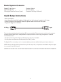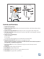
1
Instructions for Use Dental Curing Light with Optional Tooth Whitening, Lesion Detection and Soft Tissue Management (STM) 3W Diode Laser Attachments Safety Precautions (Read first before proceeding) Warning Before connecting and operating the Sapphire® Plus, read all safety instructions. When used properly and with normal precautions, the Sapphire Plus is a safe and effective multi-purpose light system. However, the Sapphire Plus is a source of high electrical voltage, intense light, and heat. This product must only be used as indicated in this manual. Before connecting the Sapphire Plus to the mains (the AC wall outlet), verify that the voltage to be applied is within the range of that specified on the identification label on the backside of the instrument. If you have any questions concerning the proper voltage, call the factory for clarification. To avoid risk of electric shock, disconnect the power cord before opening the lamp access door or removing the product cover. All repairs other than lamp replacement must be made by a factory authorized representative. Do not touch or probe other electronic components inside the product. High-intensity light can be harmful to the eyes. When the system is in use, the patient, operator, and assistant(s) must wear protective eyewear. Caution should be used to avoid accidentally starting the light outside of the mouth. To avoid possible injury, never look directly into the end of the light guide or directly into the light output on the front panel (even with protective eyewear). Never shine the light into the eyes. High-intensity dental lights should not be used by operators or on patients who may be photo-sensitive. Do not expose soft oral tissues directly to the tip of the light at close proximity. Only use the light guide supplied with the Sapphire Plus. Other light guides may not be effective and may damage the light. Do not cause excessive bending in the light guide. Do not drop the light guide or tip. Do not autoclave the light shield provided with the unit. Do not autoclave the light guide. Removable curing tip is autoclavable; Laser tip is not autoclavable. Do not use abrasives or liquid chemicals to clean the tip or the light housing. The fan at the rear of the light provides cooling when the system is on. Obstructing the air flow will cause heat buildup and will damage the system. Disconnect the Sapphire Plus power cord from the power outlet and contact the factory for service instructions if the light has been exposed to liquid spills, dropped or otherwise damaged (including the power cord), or otherwise malfunctions. Do not use in the presence of flammable materials. Do not look directly into the end of the laser tip. Caution: US Federal Law restricts the use of this device to use by or on the order of a dentist 2 Important Start-up Instructions (Follow these instructions prior to using the system) 1. Attach the AC Power Cord to the power inlet on the Sapphire Plus light source and plug into AC outlet. 2. Install the Curing, Lesion Detection or Soft Tissue Management (STM) device into front panel receptacle (black adapter insert must be removed to install STM). Make sure the device is firmly inserted all the way into the receptacle before turning on the power. If the device is not installed correctly the system display will show “no HP” meaning No Hand Piece is detected. 3. When using the built-in light meter, the handpiece should be held in the position as indicated in the illustration. The tip should be centered inside of the aperture. Positioning the tip differently may result in reduced light intensity values. 4. Do not saturate the controller keypad area with disinfectant or other liquids. Wipe the keypad surface with a damp towel and dry completely. 5. If the lamp access plate on the bottom of the system is removed to check the lamp, make sure that it is replaced correctly. The corners of the plate must fit into the outline of the cutout area and not rest on top of the edges of the surrounding metal. When installed properly all surface areas are even with each other. If the access plate is misaligned, the lamp will not activate. If the access plate is misaligned the system will show “Locd” meaning system is Locked and the lamp will not activate. Dangerous Voltage Enclosed Equipment Protected Against Dripping Water Attention: consult accompanying documents Hazard, High-Intensity Light (applies when Curing/Whitening Handpiece is attached) Attention: may be hot DO NOT use in the presence of flammable substances Protection Class BF, Insulation Class 1 Laser Radiation – Avoid eye or skin exposure to direct or scattered radiation (applies when Laser Handpiece is attached) Alternating Current Fuse 3 Table of Contents Safety Precautions....................................................................................................................................2 Important Start-up Instructions..............................................................................................................3 Table of Contents.....................................................................................................................................4 General Description and Manufacturer Information..........................................................................5 Basic System Contents...........................................................................................................................6 Quick Setup Instructions.........................................................................................................................6 Controls and Functions...........................................................................................................................7 Control Panel.............................................................................................................................................8 Display Glossary.......................................................................................................................................8 Accessories................................................................................................................................................9 Setup and Operation Instructions...................................................................................................... 10 Light Meter (Radiometer)..................................................................................................................... 11 Curing Mode.....................................................................................................................................11-12 Curing Instructions................................................................................................................................ 12 Bleach (Whitening) Mode.................................................................................................................... 13 Whitening Instructions....................................................................................................................14-15 Lesion Detection Mode........................................................................................................................ 15 STM (Soft Tissue Management) 3W Diode Laser Mode Settings............................................. 16 STM (Soft Tissue Management) Diode Laser Mode............................................................... 17-18 Sanitizing & Sterilizing........................................................................................................................... 18 Service...................................................................................................................................................... 19 Troubleshooting...................................................................................................................................... 19 Lamp Replacement Instructions......................................................................................................... 20 Fuse Replacement................................................................................................................................. 21 Transportation ........................................................................................................................................ 21 Storage..................................................................................................................................................... 21 The Den-Mat® System Specification................................................................................................. 21 The Den-Mat Sapphire STM 3W Diode Laser Specification....................................................... 22 System Warranty.................................................................................................................................... 23 Order Information.................................................................................................................. Back Cover 4 General Description The Sapphire® Plus is a multi-purpose platform that combines the capabilities of a high-intensity xenon arc lamp with specially-designed optics and a soft tissue laser. Broad spectrum visible light emissions are filtered to provide peak performance for initiating rapid polymerization of photoinitiated dental restoratives, for whitening, and as an adjunctive lesion detection device. There are separate handpieces for curing/whitening and for lesion detection that effectively utilize the visible light emissions for their indicated uses. The Sapphire Plus STM 3W Diode Laser is a third option for the Sapphire Plus System. It plugs into the Sapphire Light Source Unit’s Light Guide Port so that the xenon arc lamp’s emissions can be accessed by the curing/whitening and lesion detection handpieces. When either the Curing/Whitening or Lesion Detection Handpieces are inserted, the Sapphire Plus’ microprocessor recognizes that they have been inserted, and that the xenon arc lamp can be used when needed. By this design, the operational aspects of the curing/whitening and lesion detection functions are unchanged. When the Sapphire Plus STM laser handpiece is inserted, the Sapphire Plus STM control module microprocessor recognizes that the laser handpiece is in place and the xenon arc lamp will not ignite. Instead of receiving high-intensity visible light from the xenon arc lamp, when the Sapphire Plus STM handpiece is in place, digital signals from the STM laser microprocessor are transmitted to and from the laser handpiece circuit board along with low current DC power that energizes the STM laser’s rechargeable battery. The Sapphire Plus STM laser is intended for use as a soft tissue management device, specifically for gingivectomy, gingivoplasty, gingival troughing, gingiva, recontouring, tissue retraction for impressions, papillectomy, sulcular debridement, sulcular tissue removal, removal of granulation tissue, frenectomy, frenotomy and abcess excision. Control panels for curing/whitening and lesion detection are separate from those that control the Sapphire Plus STM laser; lock out switches are present that enable the appropriate control panel. These user interfaces offer a wide range of timing increments (curing/whitening) as well as modes and power output settings (laser). Bright display windows and LEDs provide visual status indications and clear audio signals are present to further ensure setting’s confirmation. Switches on the control panel have a wide range of timing increments and modes. Bright alphanumeric display windows provide visual indications and audio signals provide additional confirmations. When the Sapphire Plus STM laser handpiece is inserted, the Sapphire Plus STM control module microprocessor recognizes that the laser handpiece is in place and the xenon arc lamp will not ignite. Manufacturer Information Manufactured by: Den-Mat® Holdings, LLC 2727 Skyway Dr. Santa Maria, CA 93455 USA Toll Free 1-800-445-0345 Tel. 1-805-922-8491 www.denmat.com 5 Basic System Contents Sapphire® Light Source Light Guide and Tip Curing Light Protective Glasses (2 pair) Operator’s Manual AC Power Cord Composite Test Rings (200 each) Quick Setup Instructions • Select a handpiece. • Insert the proximal end of the handpiece’s light guide into the front panel receptacle until it stops. • Connect the input end of the power cord to the power module on the rear of the system. • Plug the AC plug into an AC outlet. AC Plug Input Three-conductor grounding plug with international IEC connector provided. This common power cord is used for computers and other peripheral devices and is readily available for separate purchase if a different plug configuration is needed for international customers. • The display on the front panel will light up, indicating that system power is available. • Turn the power switch (located on the back panel) to the ON ( I ) position. The Sapphire Plus is now ready for use. It is recommended that you become familiar with all system features before use. NOTE: Make sure the light guide is pushed all the way in until it stops. Also, it is important to check that the lamp access plate is on correctly if it has been removed. ATTENTION: DO NOT PULL ON THE LIGHT GUIDE CABLE TO UNPLUG THE CABLE OR MOVE THE SYSTEM 6 1 5A 3 5B 2 5C 6 9 10 11 8 5 4 7 Controls and Functions 1.Sapphire Plus Light Source 2.Sapphire Plus Control Panel: Includes control wheel and select button, mode indicator, display windows, and start/stop button. 3.Sapphire Plus Display Windows: Digital display of the pre-set time, program mode, and light meter. 4.Fiber Optic Light Guide: Flexible optical device for delivery of light. Make sure the light guide is pushed all the way in until it stops. 5.Sapphire Plus Curing Handpiece: A. Timer select button B. Timer display C. Activator button (Each handpiece has an activator button to activate the lamp.) 6.Removable Autoclavable Tip: Optical device for exact placement of light. NOTE: Foot Switch (not shown) is available for the STM attachment, which allows the operator to turn power ON ( I ) and OFF (O) using the foot. 7.Lamp Access Plate: Access area on the bottom of the light source where the lamp is removed and replaced. 8.Cooling Fan: Provides cooling to the light source. 9.Power Module: Accepts AC power cord. 10. Fuse Holders: Contains the main fuses. (see fuse replacement section) 11. Power Switch: Turns power ON ( I ) and OFF (O). 7 Control Panel START/STOP starts/stops lamp in CURE, BLEACH and SCOPE modes. UP/DOWN arrows on CONTROL WHEEL increase and decrease time and output. LEFT/RIGHT arrows on CONTROL WHEEL toggle between modes. SELECT accepts mode and setting. Display Glossary Display Meaning Next Step No HP No handpiece Ch HP Choose handpiece C1 05 Cure timer #1: 5 seconds C2 05 Cure timer #2: 5 seconds Pr Hi Bleach power: high (use whitening crystal) BL 60 Bleach timer: 60 minutes SC OP SCOPE mode Install handpiece Press RIGHT arrow to change mode; then press SELECT UP/DOWN arrows adjust time; LEFT/RIGHT arrows switch between timers Press SELECT for BLEACH mode DOWN arrow decreases power (for single tooth whitening) UP/DOWN arrows adjust time Press ACTIVATOR button on handpiece to start 8 Accessories Eyewear The protective eyewear provided with the Sapphire® Plus must be worn by the operator, assistants, and patient when the system is in use. Additional eyewear is available through DenMat® Holdings, LLC. See the back cover for ordering information. PROTECTIVE EYEWEAR REMOVABLE TIPS CAUTION: Protective glasses provided for use with the Sapphire Plus curing/ whitening attachment are not intended for use when the STM Diode Laser is used. See p.16 and the STM 3W DIODE LASER Instructions for a description of Laser Safety Eye Protection. Light Guide and Tips The Light Guide provided with the Sapphire Plus provides an optical path for transmitting light energy from the source to the tips. Both the Light Guide and removable tip are available through Den-Mat Holdings, LLC as spares or replacement parts. See the back cover for ordering information. NOTE: 2 mm and 4 mm Ceri-Taper™ Tacking Tips may be used to help to reduce placement time of LUMINEERS®. 9 2 mm 4 mm 9 mm 12 mm Setup and Operation Instructions Compatibility of Existing Sapphire® and Sapphire Plus Lights and Devices The labeling on the curing handpiece and Sapphire light source will indicate whether these are different than the new Sapphire Plus. The curing handpiece and Sapphire Light source may be labeled Sapphire, Rembrandt® Sapphire, or Sapphire Supreme. The curing and lesion detection handpieces for the new Sapphire Plus light have been designed to work with existing Sapphire lights (reverse compatible). At the same time, curing and lesion detection handpieces for existing Sapphire lights can be used with the new Sapphire Plus light (forward compatible). Using Existing Sapphire Curing and Lesion Detection Handpieces When using existing curing and lesion detection devices in the Sapphire Plus, it is necessary to manually select the correct mode of operation. When the Sapphire Plus light is powered up without a device installed in the light guide receptacle on the front of the light source, the error message “No HP” (no handpiece) will appear on the display. When existing curing or lesion detection handpieces are installed in the light source, the display windows will change from “No HP” to a flashing “Ch HP” (choose handpiece). This means that a handpiece has been recognized and the operator is being prompted to select the correct user mode. Press the LEFT arrow key to advance directly to the SCOPE MODE or press the RIGHT arrow key to step through the BLEACH, SCOPE and CURING MODES and press the SELECT button to enter that mode. Follow all other instructions for operation of that mode. Press SELECT to stay in the CURE mode and the LEFT or RIGHT arrow keys to alternate between the two curing timers C1 and C2. Using the new Sapphire Plus Curing and Lesion Detection Handpieces The curing and lesion detection handpieces for the new Sapphire Plus light have been designed to work with existing Sapphire lights (reverse compatible). Follow all operating instructions for the selected handpiece. Install Power Cord, Install Handpiece, and Power Up Install the AC power cord into the power inlet on the back of the Sapphire Plus light source and into a grounded AC socket. Insert the proximal end of the fiber optic light guide on the curing or lesion detection handpieces or soft tissue control module into the light guide receptacle on the front of the Sapphire Plus light source. Turn the power switch on the back of the system to the ON ( I ) position. Press the SELECT button to enter the Curing mode or use the LEFT or RIGHT arrow keys to choose the BLEACH or SCOPE modes and press SELECT to enter that mode. The Sapphire Plus is ready for use. It is necessary to read and understand all usage and safety precautions before use of this system. 10 Light Meter (Radiometer) Use the Sapphire Plus light meter to validate the power density (light intensity or mW/ cm2) output of the curing handpiece and lesion detection handpiece prior to each use. The light meter window is located below the system control panel. CAUTION: DO NOT SHINE STM LASER BEAM ON THE LIGHT METER WINDOW CAUTION: DO NOT USE 2mm OR 4mm TIPS ON THE LIGHT METER WINDOW When the curing tip or lesion detection handpiece is placed on the light meter window and the lamp is activated, the system automatically detects the light and changes to the RADIOMETER mode. The output reading of power density is shown on the display windows. To get an accurate reading, the curing tip must be centered directly in the light meter window and the lesion detection must be centered directly over the light meter window. Set the timer to 5 seconds and remove the tip from the light meter window as soon as you have a measurement. LIGHT METER WINDOW NOTE: It is recommended that measurements are entered into a log in order to document any changes in output over time. Proper Light Meter Readings • Curing: If light is below 300 mW/cm2, do not use for curing. High light intensity (over 1500 mW/cm2) allows fast curing. Use curing test rings provided to test the material being cured. • Lesion Detection: Light intensity must be 75 mW/cm2 (displayed as “00 75” in the display windows) or greater. If light intensity is below 75 mW/cm2, do not use. Curing Mode Timers and Control Panel Operation There are two operator-adjustable curing timers available: C1 and C2. Each timer can be set from 1 to 10 seconds. It is recommended that multiple 5-second exposures should be used for resins that need a little more time. Single exposures longer than 5 seconds should be limited to use with the 12 mm curing tip. Whenever the curing handpiece is inserted, and cure mode selected, the system defaults to the first of two curing timers. The factory preset time for both of these is 5 seconds. The indicator light next to CURE on the control panel will turn on. The display windows will show “C1” in the MODE window and “05” in the SETTING window. The exposure time setting can be increased or decreased by using the UP and DOWN arrow keys on the CONTROL WHEEL. The exposure time setting can be increased or decreased by using the UP and DOWN arrow keys on the CONTROL WHEEL.Each time the UP key is pressed, the time will increase one second; each time the DOWN key is pressed, the time will decrease one second. The time displayed in the SETTING window will display the time as it changes. Each of the two curing timers can be adjusted from 1 to 10 seconds using this method. When the timer setting is adjusted, it will stay at that setting until the next time it is changed, even when the system power is turned off. This allows the operator to use favorite settings without having to reset before each usage. 11 Curing Mode (continued) To change from the C1 to the C2 timer, press the LEFT and RIGHT arrow keys on the CONTROL WHEEL. The display windows show “C2” in the MODE window and “05” in the SETTING window. The ACTIVATOR button on the curing handpiece will activate and deactivate the lamp. The TIMER SELECT button on the curing handpiece will alternate between the C1 and C2 timers. ATTENTION: DO NOT HOLD DOWN THE START/STOP OR ACTIVATOR BUTTON. PRESS AND RELEASE. Fast Start When the curing handpiece is installed, pressing the ACTIVATOR button on the handpiece or START/STOP button on the front panel will immediately activate the lamp and start the countdown timer. The timer setting will be either the factory-default 5 seconds or the last setting, from 1 to 10 seconds, when the power was turned off. When the CURE mode is selected, it is necessary to power down or unplug the light guide to reset the system and change to BLEACH mode. Recommended Use of Both Timers When placing LUMINEERS®, set timer C1 for 2 seconds and timer C2 for 5 seconds. use C1 for spot curing LUMINEERS with the 2 mm tacking tip, and use C2 for final curing with the 9 mm tip. use the TIMER SELECT button to quickly alternate between the C1 and C2 timers. Spot curing with the 2 mm tacking tip makes clean-up of margins a breeze and greatly reduces finishing time. Curing Instructions NOTE: Clean the tip prior to use for maximum light output. ATTENTION: Do not touch the curved tip of the light guide handle to the restorative material. Hold the tip approximately 2 mm above the material to be cured! It is recommended that you test all restorative materials for the time required for complete curing prior to use. The curing test rings provided with the Sapphire are 2 mm deep x 5 mm interior diameter. Fill the ring with the restorative to be used. Set timer C1 or C2 to 5 seconds. Position the curved tip of the handpiece approximately 2 mm from the composite and start the system. After the timing cycle is completed and the light turns off, test the bottom surface for hardness using a dental probe. If the material is not completely cured, restart the system again for another 5-second exposure. Test, and repeat again, if necessary. This will give you an indication of the optimum timing increment for the specific restorative to be used. Select a new timer increment which is close to the total time it took to cure the material. Repeat the test and verify that complete curing has occurred. If curing time is longer than 5 seconds, it is recommended that you repeat an additional 5-second exposure. It is important that you maintain a log of composite materials, shades, and associated curing times. This log can also be used to monitor system performance. If the cavity preparation is deep, an incremental filling technique is recommended and each increment should be cured following the manufacturer’s guidelines or your own experience with the restorative being used. CAUTION: Do not direct the light on to unprotected gingiva or skin. 12 Bleach (Whitening) Mode After the system power is switched ON ( I ), use the RIGHT arrow key to advance to the BLEACH mode. Or, if in the CURE mode, disconnect the light guide to reset the system. use the RIGHT arrow key to advance to the BLEACH mode. BLEACH Power High Bleach 60 minutes The indicator light next to BLEACH on the control panel will turn on. The display windows will show “Pr Hi” (power high). use the DOWN arrow key to adjust power down in 5% increments. use the RIGHT arrow key to change to the bleach timer. The default timer is 60 minutes. The timer can be adjusted by using the UP and DOWN arrow keys on the CONTROL WHEEL. To adjust the power output, press the DOWN arrow key on the CONTROL WHEEL to reduce the power and the UP arrow key on the CONTROL WHEEL to increase power. Lower power is useful for single tooth whitening using the 12 mm curing probe to control heat. High power is used with the Whitening Crystal. Start the lamp by pressing the ACTIVATOR button on the handpiece or the START/STOP button on the control panel. Stop the lamp by pressing the ACTIVATOR button or START/STOP again. 13 Whitening Instructions LUMIBRITE™ Chairside Whitening System contains stabilized hydrogen peroxide for maximum whitening ability and fluoride for overall oral health, and a proven desensitizer for patient comfort. See the back cover for ordering information. Remove the LUMIBRITE Chairside whitening gel syringe from the refrigerator and allow it to come to room temperature for about 30 minutes before it is used. 1. Prophy teeth to remove calculus and extrinsic stains before beginning the whitening treatment. 2. Take “before” photographs and record tooth color using a shade guide arranged in bleaching order. 3. Insert cheek retractors. Have the patient bite down and rest tongue on a tongue block. 4. Air-dry the gingival tissue and teeth. 5. Using the dispensing tip, apply Paint-On Dental Dam to the gingiva to isolate gums around the selected teeth. Overlap the dental dam onto the gingival tissue of adjacent teeth (about 0.5 mm) and light-cure for 1–2 seconds per tip width with a Sapphire® Plasma Arc Curing (PAC) light. 6. Once the Paint-On Dental Dam is cured, apply Lip Moisturizer provided in the kit to the lips and mucosa, applying well beyond the vermillion border. 7. Remove the tip from the end of the LUMIBRITE desensitizing enhancer recappable syringe and dispense a portion of the LUMIBRITE desensitizing enhancer into a dappen dish. Apply in a very thin (about 0.2 mm) layer on the labial surface of the teeth using the brush applicator provided in the kit and allow to sit for one minute. Wipe off any excess. Firmly recap the LUMIBRITE desensitizing enhancer syringe. 8. Prepare the auto-mix syringe. - Align the wedge-shaped key on edge of the static mixer housing with the opening in the syringe flange. - Push the static mixing tip onto the syringe and turn 90° clockwise until it stops. 9. Dispense a portion of the LUMIBRITE whitening gel into a separate dappen dish. Use the brush applicator to apply a 1–1.5 mm layer onto the labial surface of the teeth. Distribute the gel evenly over the teeth treated in Step 7 with the LUMIBRITE desensitizing enhancer. Agitate to mix LUMIBRITE desensitizer and LUMIBRITE whitening gel. 10.Install the Sapphire whitening crystal in place of the curing tip on the end of the Sapphire PAC light pistol. 11.Position the Sapphire whitening crystal close to and directly in front of the teeth, using a combination of the articulating arm and chair adjustments. Center the Sapphire whitening crystal 1/4 to 1/2 inch from the teeth within the cheek retractor with the outer edges touching (if possible). 12.Press the Optional button on the Sapphire PAC light keypad, then press 2 to select bleaching mode. The letters bL (bleach) will appear in the Program window, the number 60 will appear in the seconds window and 60 minutes will appear on the pistol handle. 14 13. Press the Start or pistol activator button to start the bleaching process. The number 60 (minutes) appears in the Program window and seconds begin to count down in the Seconds window. When the Sapphire light beeps, fifteen (15) minutes have elapsed. Check on the comfort of the patient. After the second beep, 30 minutes have elapsed. 14. Move the Sapphire whitening crystal away from the teeth. Leave the Paint-On Dental Dam in place and vacuum gel from the teeth. Wipe with gauze and rinse the teeth while suctioning. Avoid splatter. Some patients with heavy discoloration or areas of unseen hypocalcification may need another 30-minute session to achieve desired whitening results. Evaluate the results with the patient, if possible. Note: In some cases you may have attained acceptable whitening in the first 30-minute session. If so, a second session is not indicated. Note: In some cases, it may be necessary to peel away the Paint-On Dental Dam to make a shade determination. If the Paint-On Dental Dam is removed and another 30-minute application is indicated, remember to reapply the Paint-On Dental Dam to protect the gingival tissue. 15. If another 30-minute session is desired, reapply both desensitizing enhancer and whitening gel following instructions beginning with Step 7. Note: Be sure to inspect the Paint-On Dental Dam for any cracking or lifting before re-applying the desensitizing enhancer and whitening gel. If the seal has broken from the tissue, it is recommended to remove and replace the Paint-On Dental Dam and begin with Step 4. 16. At the end of the second 30-minute session, vacuum gel from the teeth, wipe away with gauze and rinse the teeth while suctioning. Avoid splatter. 17. Use a shade guide arranged in bleaching order to compare the color of the whitened teeth to the original shade recorded in Step 2 and take “after” photographs. Lesion Detection Mode Insert the lesion detection fiber optic light guide into the light guide port, making sure it is completely seated. Press the LEFT arrow key to advance to the Scope Mode and press the SELECT button to enter the Scope Mode. The indicator light next to SCOPE on the control panel will turn on, and “SC OP” (scope) will appear on the display windows. The scope light output is controlled by the ACTIVATOR button on the lesion detection handpiece or the START/ STOP button (labeled “STOP”) on the control panel. There is no countdown timer. The lamp will run as long as necessary for the examination. Start the lamp by pressing the ACTIVATOR button on the handpiece or the START/STOP button on the control panel. Stop the lamp by pressing the ACTIVATOR button or START/STOP button again. Fast Scope Operation When the scope handpiece is installed, pressing the LEFT arrow key on the CONTROL WHEEL will advance the system to the SCOPE mode. Pressing the ACTIVATOR button on the handpiece will immediately activate the lamp. The SCOPE mode does not have a timer. Press the ACTIVATOR button a second time to deactivate the lamp. NOTE: Consult the Sapphire Lesion Detection user’s Manual for complete instructions on operating the Sapphire Lesion Detection adjunctive handpiece. 15 STM (Soft Tissue Management) 3W Diode Laser Mode Settings NOTE: DO NOT ATTEMPT TO OPERATE THE SAPPHIRE® PLUS STM 3W DIODE LASER SYSTEM WITHOUT FIRST READING AND UNDERSTANDING ALL LASER SAFETY INSTRUCTIONS. For complete information on using the Sapphire Plus STM 3W Diode Laser and performing STM 3W Diode Laser procedures, refer to the Sapphire Plus STM 3W Diode Laser Instructions for Use documentation. Warning: Laser Safety Eye Protection MUST BE WORN by the Operator, Patient, Assistant, and anyone present when the laser is activated. Eye Protection must conform to Specification DIN EN207 Annex II of the Directive 89/686/EEC with optical density in 800nm-818nm of OD 4+ such as NoIR Laser Company filter model DII. The STM 3W Diode Laser offers two operation modes: CW (CONTINUOUS WAVE) and PULSE (4Hz). The following instructions will describe how to control both. Remove the black adapter insert (if present) from the light guide port of the Sapphire Plus System and insert the STM 3W Diode Laser Control Module into the light guide port. Insert the Sapphire Plus STM key into the Sapphire Plus STM Diode Laser unit and turn it to the “ON” position. Plug the STM 3W Diode Laser handpiece into the Light Guide Port on the Laser Unit. When the STM 3W Diode Laser handpiece is attached to the STM 3W Diode Laser unit, the auto-detect feature will activate the unit and cause the display to light. The unit will then be in STAND-BY status. CHARGE BATTERY BEFORE USING: Upon receipt, install the Sapphire Plus Soft Tissue Management (STM) control module into the Sapphire Plus light source. Turn the power switch of the Sapphire Plus light source ON. For a more rapid charge, use the auxiliary power s upply provided with the Sapphire Plus STM system. Plug the auxiliary power supply into an AC outlet and insert the plug into the STM control module. NOTE: All Sapphire plus attachments can be plugged into the Sapphire plus when the STM control panel is installed. For use of non-Laser attachments, the key must be turned to the “OFF” position. With the key in the “ON” position and the STM 3W Diode Laser handpiece attached, the unit defaults to the Continuous Wave (CW) mode and the indicator light next to CW on the control panel turns on. The power setting will default to 0.8 Watts and will be displayed in the LASER POWER window. NOTE: A flashing red “READY” indicator light and blank LASER POWER window indicate that additional power is required and that the STM 3W Diode Laser auxiliary power supply must be attached to the jack on the side of the STM Control Unit. Power can be adjusted by using the UP and DOWN arrow keys to increase (up) or decrease (down) the power. settings may not be changed when the laser working beam is emitting. 16 STM 3W Diode Laser Mode (continued) STAND-BY, CW Mode 0.8W (default) output STAND-BY, P Mode 0.8W output Use the CW/P button to toggle between the CW (CONTINUOUS WAVE) AND PULSE modes. Laser in READY Mode @ 0.8W output Press the READY button in either mode to prepare the unit for Laser activation. A GREEN indicator will glow next to the button identifying the “READY” status. Changing the mode or power level releases the unit from “READY” status requiring the user to “SELECT” the new setting by pressing the READY button again. Setting may not be changed when the laser is activated. In READY, the unit’s Aiming Beam is emitted. The STM Diode Laser can be activated using either the handpiece or foot switch, but not both at the same time. The footswitch, if attached, takes priority over the handpiece switch. Unplug the footswitch from the STM 3W Diode Laser Unit if it will not be used. When the ACTIVATOR button on the STM handpiece or the footswitch is depressed and held down, the active mode indicator will turn from GREEN to RED and a audible “chirp” is produced, indicating that the Laser working beam has been activated. The STM handpiece will then begin delivering laser emissions to the selected tissue by means of the disposable 400 micron fiber delivery tip after a 200 micro-second delay. Release the ACTIVATOR button or footswitch to deactivate the working power. Laser emissions will not be transmitted unless a Fiber Optic Tip is fully inserted into the end of the Handpiece. 17 STM 3W Diode Laser Mode (continued) The STM 3W Diode Laser unit may be deactivated at any time by pressing the Emergency “STOP” button on the STM 3W Diode Laser unit control panel. This action deactivates the unit function in any mode, at any power setting, and whether or not the Laser working power is active. To reset the unit for use, depress and hold down the “STOP” button for 5 seconds; this places the unit in STAND-BY Mode. Sanitizing & Sterilizing Sapphire® Plus STM control panel showing that the laser is emitting in CW at 0.8 W Sterilizing The Whitening Crystal Clean with a mild, non-abrasive, liquid soap and thoroughly dry all surfaces. Cold sterilize with solutions containing glutaraldehyde, low concentrations of hydrogen peroxide, isopropyl alcohol or other disinfectants containing mostly inert ingredients. Sterilizing The Curing Tip Clean the tip regularly with composite solvent. The removable tip must be sterilized using standard autoclave procedures for stainless steel instruments (135º C). Use a sterilization bag and leave sealed for future use. Failure to sterilize tips between patients increases the risk of patient-to-patient infection. Sterilizing The Single Use/Disposable STM Tip Cold sterilize with solutions containing glutaraldehyde, hydrogen peroxide, isopropyl alcohol or other disinfectants containing mostly inert ingredients. CAUTION: Do Not Autoclave The Light Guide! Sanitizing The Light Guide and Handle The light guide cannot be autoclaved. It should be sanitized by using a non-abrasive disinfectant. Do not use glutaraldehyde-type disinfectants. Cleaning The Sapphire Plus System NOTE: Unplug the power cord prior to cleaning with any liquid. Allow the system to cool prior to cleaning. Avoid spilling any liquid on the system. Do not use flammable liquids to clean the main system or light guide. If the internal electronics are exposed to any liquid, disconnect the power. Do not attempt to start the system. Contact the factory for instructions at 1-800-445-0345. Clean the main system by using a mild, non-abrasive disinfectant. Do not saturate the control panel with liquid. Wipe with a damp towel and dry completely. Replacement Parts Additional tips, shields, and curing rings, light guides and lamp modules are available from Den-Mat® Holdings, LLC. See back cover for ordering information. 18 Service Minor problems can be quickly identified and resolved. These are usually related to the electrical power connection or light guide connection. All other malfunctions must be diagnosed and repaired by Den-Mat Holdings, LLC. Contact Den-Mat Holdings, LLC for technical support at 1-800-445-0345. WARNING: ORANGE SAFETY GLASSES MUST BE WORN DURING TESTING. Troubleshooting Problem The control panel and handpiece display does not light up. Buttons do not respond. Corrective action Check the AC electrical outlet, power cord, and power input on the light to verify that all connections are secure and that AC power is on at the outlet. Verify that the power switch is in the ON ( I ) position. Problem The control panel display lights up but the handpiece display does not light. Lamp does not start when the Activator button on the handpiece is pressed. Corrective action Being careful not to look directly at the distal end of the light guide, press the START/STOP button on the front panel. If the lamp does not come on, move to the next step. If the lamp comes on, recheck the light guide connections. Disconnect the light guide and firmly reinstall, making sure that it is plugged in all the way. Rotate the light guide 1/4 to 1/2 turn in the light guide receptacle. Look for the display to light up on the handpiece. If the display on the handpiece responds, try starting the light again with the Activator button. Problem The control panel display lights up and the CONTROL WHEEL and Timer Select button work, but the Start/STOP button and Activator button do not start the lamp. Corrective action Contact Den-Mat Holdings, LLC for technical support at 1-800-445-0345. Problem Light output is low or curing of the composite is slow. Corrective action Verify the light guide is plugged all the way into the receptacle on the front of the unit. Check the tip for contamination, scratches, or breaks. Clean the tip with composite solvent. Check the light guide for damage. Follow instructions for checking and replacing the lamp. If corrective action does not resolve the problem, contact Den-Mat Holdings, LLC for technical support at 1-800-445-0345. This includes possible lamp replacement or return of the system for repair. 19 Lamp Replacement Instructions warning: only a qualified service technician may replace the system lamp. protective eyewear must be worn. never point the window of the lamp to unprotected tissue. Symptoms indicating need for replacement are: 1. Low intensity on system light meter. 2. Lamp fails while in use or does not turn on. To Remove the Old Lamp 1. Turn unit off and unplug the power cord from its power source. 2. Wait for the unit and the lamp to cool. 3. Unscrew thumbscrews to remove the lamp access plate. 4. Grasp lamp and slide towards you to remove from light source. 5. Unplug the lamp from the 2-pin lamp socket. To Insert New Lamp 1. Orient the lamp facing forward in the lamp guides on the chassis. 2. Push toward the top of the unit until the lamp slides securely onto the lamp pins. 3. Replace the lamp access plate and tighten thumbscrews. Note: Make sure the access plate fits correctly in the cutout provided. All corners should be even with the surrounding surfaces. If the access plate is misaligned, the unit may not receive AC power. Unscrew thumbscrews to remove access door. HANDLES 20 BRASS SOCKETS Fuse Replacement warning: only a qualified service technician may replace system fuses. 1. If the Sapphire® Plus source fails to operate after power is applied, disconnect the power cord from AC wall outlet before checking the fuse(s). Switch the power switch to the OFF (O) position. 2. Check for blown fuses by removing the fuse covers using a flat blade screw driver (medium size) or equivalent. 3. Replace the blown fuse(s) with the same size and rating. Fuses are 6 amp AGC-6 1/4” x 11/4” Fast Acting. 4. Replace fuse cover. 5. Reconnect the power cord. 6. Switch the power switch to the on ( I ) position. 7. If the unit fails to operate properly again, contact Den-Mat® Holdings, LLC for repair at 1-800-445-0345. Transportation When transporting the Sapphire Plus, remove the power cord and the light guide from the Sapphire Plus light source. Hold the handle or carry it with both hands, one hand underneath the unit to insure safety. To prevent damage to the Sapphire Plus during transportation, it is highly recommended that the unit be wrapped with bubble wrap and placed in a shipping box or similar packing materials. Storage Store the Sapphire Plus and accessories in a clean area and maintain the room temperature as follows: Storage Environment (Operating): Ambient Temperature 6˚ C to 45˚ C (43˚ F to 113˚ F) Transportation & Storage Environment (Non-operating): Ambient Temperature -50˚ C to 70˚ C (-122˚ F to 158˚ F) Relative Humidity 10-95% at 35˚ C (95˚ F) DO NOT bend the AC cord severely, apply excessive force, pull, twist, or squeeze the power cable. DO NOT bend the light guide severely, apply excessive force, pull, twist, or squeeze the light guide. DO NOT subject the Sapphire Plus to excess impact during transportation; this may cause the unit to malfunction. AVOID placing the Sapphire Plus in direct sunlight or high temperature. System Electromagnetic Information for the Sapphire Light Source Unit (per IEC 60601-1-2) The Sapphire Plus Light’s RF emissions are very low and are not likely to cause interference in nearby electrical equipment. The Sapphire Light (Class B) is suitable for use in all establishments, including those directly connected to the public low-voltage power supply network that supplies buildings used for domestic purposes. The Den-Mat Holdings, LLC System Specification •The light source is Class I: The Den-Mat Holdings, LLC light source relies upon the connection to the protective earth conductor of the installation to prevent shock hazards. •The light source is Type BF: The Den-Mat Holdings, LLC light source’s applied part is floating from earth. •Classification of the light source against ingress of liquids: Ordinary Equipment (IPX0) – This Den-Mat Holdings, LLC light source provides no protection against the ingress of water. •Classification against Flammable Vapors with Air: This Den-Mat Holdings, LLC light source is not suitable for use in the presence of a Flammable Anaesthetic Mixture with Air, Oxygen or Nitrous oxide. 21 The Den-Mat® Holdings, LLC Sapphire STM 3W Diode Laser Specification STM Diode Laser Unit: Style: Laser Classification: Wavelength: Beam Divergence: Power Range: Hertz rate (Pulsed): Pulse Duration: Duty Cycle: Aiming Beam: Audible signal: Visual signal: Power Supply: Auxiliary Power: Plug-In accessory for Sapphire® Plus System Laser diode Class 4 laser device (per IEC 60825) 808 nm ±5 nm 9° ± 1° 100 mW to 3 W fixed 4 Hz fixed 0.125 seconds Pulsed mode 50%, fixed Continuous wave 100% 640 (± 10)nm, 0.4 mW maximum output Yes Yes Derived from Sapphire Plus System 5 VDC supplied from 110 - 120 VAC @ 60 Hz or 220 – 240 VAC @ 50 Hz Power Adapter Complies with: IEC 60601-1-2, IEC 60601-1, IEC 60601-2-22 and IEC 60825-1; 21 CFR 1040.10 and 1040.11 with permissible deviations pursuant to Laser Notice 50, dated July 21, 2001. Handpiece: Length: Diameter: Tip removal: Activation method: Power cable: Aseptic care: 5.20 in 0.65 in Manual friction-fit Electrical contact on handpiece/ Footswitch control (optional) 72 in X 0.26 in Wipe with appropriate disinfecting solution Tips: Removable, Single-Use Disposable Fused Silica, coated 400 μm X 2 in. Fiber Type: Material: Size: Style: 22 System Warranty When used under normal operating conditions as described in this manual, the Sapphire® Plus system (main system, light guide, and curing tip) is warranted to be free of defects in workmanship and materials for one (1) year from the date of original shipment, and the power supply and lamp module are warranted to be free of defects in workmanship and materials for three (3) years from the date of original shipment. Within the warranty period, if service is required, the system must be returned to Den-Mat® Holdings, LLC for diagnostics and repair. Contact the factory to receive Return Authorization prior to shipping. The Return Authorization will include a pick-up notice (Call Tag) for a common carrier to return the merchandise to Den-Mat Holdings, LLC. Freight charges for returns within the warranty period will be paid by Den-Mat Holdings, LLC pending the results of evaluation of cause of the failure or damage. Freight charges for returns outside of the warranty period will be paid by the customer. The outside shipping container and any accompanying documents must be clearly marked “Repair Return.” Use only the original shipping container or other adequate shipping materials to protect the system in transit. All returns will be evaluated for the cause and extent of failure or damage by Den-Mat Holdings, LLC Service Representatives. Subject to the results of this evaluation, Den-Mat Holdings, LLC will authorize warranty repair or will contact the customer with a price quotation for the cost of repairs for failures and damages occurring as a result of misuse, improper operation, or for merchandise outside of the warranty period. This is a limited warranty and the liability of Den-Mat Holdings, LLC is to repair or replace the system. Repairs may be made with new or refurbished parts at the manufacturer’s discretion. Den-Mat Holdings, LLC has no liability to refund any part of the purchase price and no liability for consequential damages, loss of profits, and damages to person or injury by reasons of any defects in said system from any cause whatsoever. Any buyer who purchases said system acknowledges their familiarity with the terms, conditions, and provisions of this limited warranty and purchases said system agreeing to such terms, conditions, and provisions. Buyer purchases the Sapphire Plus system from Den-Mat Holdings, LLC on the terms, conditions, and provisions of this limited warranty and waives all other rights and claims against Den-Mat Holdings, LLC for any damages or remedies exceeding said limited warranty. Den-Mat Holdings, LLC 2727 Skyway Dr. Santa Maria, CA 93455 USA Toll Free 1-800-445-0345 Tel. 1-805-922-8491 www.denmat.com 23 CALL YOUR Den-Mat® Holdings, LLC TECHNICAL SALES REPRESENTATIVE TO LEARN HOW TO INCREASE PROFITS WITH YOUR Sapphire® Plus. LUMIBRITE Chairside #035359155 US/#035359159 CN Whiten patients’ teeth comfortably and efficiently when combined with Sapphire Plus and the whitening crystal. Restorative Materials Virtuoso® Flowable Custom Kit #030381800 A low-viscosity, easy-flow restorative material with excellent physical properties. Virtuoso® Universal Introductory Kit #030381950 A nanohybrid for posterior and anterior restorations. Ultra-Bond® Plus #032599750 Optimal viscosity for cementation of all porcelain restorations in a convenient, auto-mixing syringe system. Core Paste® XP Syringe #030654110 The recognized standard in core build-up materials in a fast, auto-mixing syringe that can be easily syringed directly into canals. Infinity® Syringeable Value Kit #039680100 Self-adhesive, dual-cure resin cement with fluoride for placement of gold and PFM crown/bridge restorations. Replacement Parts Description Sapphire® Lamp Standard Curing Tip 9 mm Standard Curing Tip 12 mm Ceri-Taper 2 mm Tacking Tip Ceri-Taper 4 mm Tacking Tip Sapphire Light Guide Curing Test Rings (bag of 200) Protective Eyeglasses (1 pair) Protective Light Shield Item Number 043951176 033958519 033958503 033958506 033958501 033958553 043952114 043921901 043957515 Part No. 033968000 CALL 1-800-445-0345 TO ORDER ©2012 Den-Mat® Holdings, LLC. World Rights Reserved. 823057810 03/12CO