1
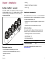
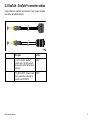
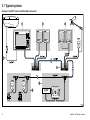
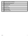
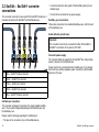
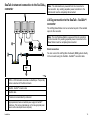
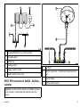
SeaTalk-SeaTalkng converter
Handbook
Trademarks and registered trademarks
Autohelm, hsb2, RayTech Navigator, Sail Pilot, SeaTalk, SeaTalkNG, SeaTalkHS and Sportpilot are registered trademarks of Raymarine
UK Limited. RayTalk, Seahawk, Smartpilot, Pathfinder and Raymarine are registered trademarks of Raymarine Holdings Limited.
All other product names are trademarks or registered trademarks of their respective owners.
Fair Use Statement
You may print no more than three copies of this manual for your own use. You may not make any further copies or distribute or use the
manual in any other way including without limitation exploiting the manual commercially or giving or selling copies to third parties.
Copyright ©2010 Raymarine UK Ltd. All rights reserved.
ENGLISH
Document number: 87121-3
Date: 06-2010
Chapter 1: Introduction
• Heading
• Navigation Data (Waypoint information)
• Rudder angle
SeaTalk - SeaTalkng converter
The SeaTalk - SeaTalkng converter allows connection of a range of
SeaTalk compatible products to the SeaTalkng network. It contains
electronics to bridge communications between the 2, allowing
information to be shared.
Handbook information
This handbook describes how to include the SeaTalk to SeaTalkng
converter within the system of Raymarine electronics on your boat.
It includes information to help you:
• understand which Raymarine equipment is compatible with the
converter,
• install and connect the converter within your system.
Additional handbooks
You may also need the additional information included in the
SeaTalkng reference manual. In particular for assistance with:
• constructing the SeaTalkng network and backbone,
• connecting power, and
• LEN loading calculations.
D11804-1
Data types supported
Description
Part number
SeaTalkng reference manual
81300
All documents are available to download as PDFs from
www.raymarine.com.
The converter supports the following types of data:
• Instrument and environment (Depth, Speed, Wind etc.)
• MOB (Man Overboard)
• GPS
Introduction
5
Important information
Warning: Potential ignition source
This product is NOT approved for use in
hazardous/flammable atmospheres. Do NOT install in
a hazardous/flammable atmosphere (such as in an
engine room or near fuel tanks).
Caution: Power supply protection
When installing this product ensure the power source
is adequately protected by means of a suitably-rated
fuse or automatic circuit breaker.
Warning: Product installation and
operation
This product must be installed and operated in
accordance with the instructions provided. Failure to
do so could result in personal injury, damage to your
boat and/or poor product performance.
Caution: Service and maintenance
This product contains no user serviceable
components. Please refer all maintenance and repair
to authorized Raymarine dealers. Unauthorized repair
may affect your warranty.
Warning: Switch off power supply
Ensure the boat’s power supply is switched OFF
before starting to install this product. Do NOT connect
or disconnect equipment with the power switched on,
unless instructed in this document.
6
Declaration of conformity
Raymarine Ltd. declares that the SeaTalk to SeaTalkng converter
is in compliance with the essential requirements of EMC directive
2004/108/EC.
The original Declaration of Conformity certificate may be viewed on
the relevant product page at www.raymarine.com
EMC installation guidelines
Raymarine equipment and accessories conform to the appropriate
Electromagnetic Compatibility (EMC) regulations, to minimize
electromagnetic interference between equipment and minimize the
effect such interference could have on the performance of your
system
Correct installation is required to ensure that EMC performance is
not compromised.
For optimum EMC performance we recommend that wherever
possible:
• Raymarine equipment and cables connected to it are:
– At least 1 m (3 ft) from any equipment transmitting or cables
carrying radio signals e.g. VHF radios, cables and antennas.
In the case of SSB radios, the distance should be increased
to 7 ft (2 m).
– More than 2 m (7 ft) from the path of a radar beam. A radar
beam can normally be assumed to spread 20 degrees above
and below the radiating element.
• The product is supplied from a separate battery from that used
for engine start. This is important to prevent erratic behavior
and data loss which can occur if the engine start does not have
a separate battery.
• Raymarine specified cables are used.
• Cables are not cut or extended, unless doing so is detailed in
the installation manual.
SeaTalk - SeaTalk ng converter
Note: Where constraints on the installation prevent any of
the above recommendations, always ensure the maximum
possible separation between different items of electrical
equipment, to provide the best conditions for EMC performance
throughout the installation
Product disposal
Dispose of this product in accordance with the WEEE Directive.
Water ingress
Water ingress disclaimer
Although the waterproof rating capacity of Raymarine products
exceeds that called for by the IPX6 standard, water intrusion
and subsequent equipment failure may occur if any Raymarine
equipment is subjected to commercial high pressure washing.
Raymarine will not warrant equipment subjected to high pressure
washing.
The Waste Electrical and Electronic Equipment (WEEE)
Directive requires the recycling of waste electrical and electronic
equipment. Whilst the WEEE Directive does not apply to some
Raymarine products, we support its policy and ask you to be aware
of how to dispose of this product.
Technical accuracy
To the best of our knowledge, the information in this document was
correct at the time it was produced. However, Raymarine cannot
accept liability for any inaccuracies or omissions it may contain. In
addition, our policy of continuous product improvement may change
specifications without notice. As a result, Raymarine cannot accept
liability for any differences between the product and this document.
Warranty registration
To register your Raymarine product ownership, please take a few
minutes to fill out the warranty registration card found in the box, or
visit www.raymarine.com and register on-line.
It is important that you register your product to receive full warranty
benefits. Your unit package includes a bar code label indicating the
serial number of the unit. You should stick this label to the warranty
registration card.
Introduction
7
8
SeaTalk - SeaTalk ng converter
Chapter 2: Parts and accessories
Chapter contents
•
2.1 Parts supplied on page 10
•
2.2 SeaTalk - SeaTalkng converter cables on page 11
Parts and accessories
9
2.1 Parts supplied
Note: Fit the blanking plugs supplied into any unused SeaTalkng
connection.
The following items are included with the SeaTalk - SeaTalkng
converter kit.
1
4
2
3
5
6
D11805-3
1
SeaTalk - SeaTalkng converter
2
SeaTalkng terminator (x2)
3
SeaTalk ng blanking plugs (x2)
4
400 mm (15 in) SeaTalk - SeaTalkng converter cable. This
cable connects the converter to the first SeaTalk device on
the spur.
5
SeaTalkng power cable
6
1 m (3.3 ft) SeaTalkng spur cable
10
SeaTalk - SeaTalk ng converter
2.2 SeaTalk - SeaTalkng converter cables
These cables are available as accessories. They are also included
with some compatible products.
1
2
D11824-1
Description
Part No.
1
1 m (3.3 ft) SeaTalk - SeaTalkng
converter cable. This cable connects
the converter to the first SeaTalk device
on the spur.
A22164
2
10 m (32.8 ft) RS125 - Converter cable.
This is required when connecting the
converter to an RS125 GPS.
R32120
Parts and accessories
11
12
SeaTalk - SeaTalk ng converter
Chapter 3: Installation
Chapter contents
•
3.1 Typical systems on page 14
•
3.2 SeaTalk - SeaTalkng converter connections on page 18
•
3.3 Making SeaTalkng connections on page 22
•
3.4 System checks on page 23
Installation
13
3.1 Typical systems
Example: SeaTalkng system with SeaTalk instruments
1
2
CANCEL
ENTER
3
CANCEL
MENU
ENTER
MENU
SeaTalk
SeaTalkng
7
SeaTalkng
SeaTalkng
SeaTalkhs
4
SeaTalkng
5
6
12 / 24 V
SMARTPILOT
D11806-1
14
SeaTalk - SeaTalk ng converter
1
Multifunction display with integrated GPS (e.g. C-Series Widescreen)
2
SeaTalkng autopilot controller and master instrument (e.g. ST70)
3
SeaTalk repeat instruments (e.g ST60+)
4
SeaTalk - SeaTalkng converter
5
SeaTalkng autopilot course computer
6
Transducers connected via SeaTalkng
7
SeaTalkhs connection (e.g. for digital radar)
Installation
15
Example: SeaTalk system with SeaTalkng multifunction display
1
2
3
4
SeaTalk
SeaTalkng
12 V
SeaTalk
SeaTalk
SeaTalkhs
SeaTalkhs
7
SeaTalk /
NMEA0183
SeaTalkng
6
5
SeaTalkhs
D11812-1
1
Multifunction display
2
SeaTalk autopilot system (This cannot be connected to the converter.)
16
SeaTalk - SeaTalk ng converter
3
SeaTalk spur containing instruments and MOB system
4
SeaTalk spur containing RS125 GPS
5&6
SeaTalk - SeaTalkng converter
7
SeaTalkhs network (e.g. for digital sounder and radar)
Autopilot restrictions
Important: A SeaTalk autopilot or associated controller must not
be connected to the SeaTalk - SeaTalkng converter.
SeaTalkng is a proprietary extension to NMEA 2000 and the proven
CAN bus technology. Compatible NMEA 2000 and SeaTalk /
SeaTalk2 devices can also be connected using the appropriate
interfaces or adaptor cables as required.
There are restrictions as to how an autopilot is connected in a
system containing a SeaTalk - SeaTalkng converter.
• SeaTalkng autopilot (e.g. SPX course computer with ST70
controller) — This can be connected as part of the SeaTalkng
system in the usual manner. However any SeaTalk cable from the
autopilot must NOT be connected to the converter.
• SeaTalk autopilot (e.g. S1, S2 or S3 course computer with
ST6002 controller) — This cannot be connected to the converter,
nor to any device on the converter’s SeaTalk spur. A SeaTalk
autopilot will usually be connected directly to the multifunction
display.
Seatalkng
SeaTalkng (Next Generation) is an enhanced protocol for connection
of compatible marine instruments and equipment. It replaces the
older SeaTalk and SeaTalk2 protocols.
SeaTalkng utilizes a single backbone to which compatible
instruments connect using a spur. Data and power are carried within
the backbone. Devices that have a low draw can be powered from
the network, although high current equipment will need to have a
separate power connection.
Installation
17
3.2 SeaTalk - SeaTalkng converter
connections
• It cannot be linked to other parts of the SeaTalk system (it is an
isolated spur).
The converter connects in line as part of the SeaTalkng backbone. It
provides connections for SeaTalkng and SeaTalk devices.
• It must not be connected to any power supply.
SeaTalkng spur connections
These allow connection of a standard SeaTalkng spur, and form part
of the SeaTalkng bus.
Avoid data and ground loops
Important:
The converter must only be connected to either the SeaTalk or
SeaTalkng connections of any device, NOT both.
Converter power supply
The converter takes its power from the SeaTalkng bus and provides
power to devices on the SeaTalk spur.
1
2
3
4
5
D11807-1
1
Blue — SeaTalkng backbone connection
2
White — SeaTalkng spur connection
3
Yellow — SeaTalk spur connection
4
White — SeaTalkng spur connection
5
Blue — SeaTalkng backbone connection
Power must not be connected into the SeaTalk spur. To be certain,
disconnect any existing separate power connection at the SeaTalk
devices on the spur.
SeaTalk spur connection
The converter will support connection of a single isolated SeaTalk
spur. The converter bridges data between this SeaTalk spur and
the SeaTalkng bus.
Please note the following regarding the SeaTalk spur:
• The spur is for connection of up to 5 SeaTalk devices.
18
SeaTalk - SeaTalk ng converter
SeaTalk instrument connection to the SeaTalkng
converter
Note: The instruments are powered from the connection to
the converter. Any existing separate power connection to the
instruments must be completely disconnected.
1
LifeTag connection to the SeaTalk - SeaTalkng
converter
The LifeTag Base Station can be connected as part of the isolated
spur into the converter.
2
Note: The LifeTag Base Station is powered from its connection
to the converter. Any existing separate power connection to the
Base Station must be completely disconnected.
3
4
Direct connection
You can connect the LifeTag Man Overboard (MOB) system directly
to the converter using the SeaTalk - SeaTalkng converter cable.
12V
5
D11808-1
1
ST60+ or ST40 instruments connected on a SeaTalk spur. The spur may
contain a maximum of 5 SeaTalk instruments.
2
SeaTalk - SeaTalkng converter cable.
3
SeaTalk cable.
4
Transducers connected directly to instrument.
5
Appropriate rated, fused and switched power supply into SeaTalkng
backbone. (This may be a dedicated spur, or from an appropriate power
source such as an autopilot course computer.)
Installation
19
Connection via a SeaTalk block
The LifeTag Base Station and converter can be connected using a
SeaTalk block. This may be useful in an existing installation where
the Base Station already has the SeaTalk cable attached.
1
1
1
2
3
2
2
3
6
3
4
D11822-1
5
4
1
LifeTag Base Station
2
SeaTalk - SeaTalk ng converter cable
1
LifeTag Base Station
3
SeaTalkng backbone
2
SeaTalk cable (bare ends into Base Station)
4
SeaTalk - SeaTalkng converter
3
SeaTalk block
4
SeaTalkng backbone
Connection colors
D11810-1
1
Red (12 V)
5
SeaTalk to SeaTalkng converter
2
Screen
6
SeaTalk - SeaTalk ng converter cable
3
Yellow (SeaTalk data)
Connection into a compatible device
The MOB can be connected into a compatible device on the
SeaTalk spur.
20
SeaTalk - SeaTalk ng converter
1
2
1
3
6
2
5
4
D11821-1
1
Compatible SeaTalk device (e.g. an ST60+ instrument)
2
LifeTag Base Station
3
SeaTalk cable
4
SeaTalkng
5
SeaTalk to SeaTalkng converter
6
SeaTalk - SeaTalkng converter cable
3
backbone
RS125 GPS connection to SeaTalk converter
SeaTalkng
4
D11809-2
1
RS125 GPS
2
RS125 to converter cable — The GPS must be the only device on this
spur.
3
SeaTalkng backbone
4
SeaTalk - SeaTalkng converter
Important: The GPS connects directly to the SeaTalk connection
on the converter. It cannot share this connection with other
devices.
Installation
21
3.3 Making SeaTalkng connections
Cable types and length
1. Rotate collar to UNLOCKED position (so molded arrows are
aligned).
2. Ensure cable end connector is correctly oriented, then fully insert.
It is important to use cables of the appropriate type and length
• Unless otherwise stated use only standard cables of the correct
type, supplied by Raymarine.
• Ensure that any non-Raymarine cables are of the correct quality
and gauge. For example, longer power cable runs may require
larger wire gauges to minimize voltage drop along the run.
Routing cables
Cables must be routed correctly, to maximize performance and
prolong cable life.
• Do NOT bend cables excessively. Wherever possible, ensure a
minimum bend radius of 100 mm.
D11827-1
3. Rotate collar (2 clicks) until it snaps into the LOCKED position
(almost one quarter turn).
Minimum bend
200 mm (8 in)
diameter
Minimum bend of cable
100 mm (4 in) radius
• Protect all cables from physical damage and exposure to heat.
Use trunking or conduit where possible. Do NOT run cables
through bilges or doorways, or close to moving or hot objects.
• Secure cables in place using tie-wraps or lacing twine. Coil any
extra cable and tie it out of the way.
• Where a cable passes through an exposed bulkhead or deckhead,
use a suitable watertight feed-through.
• Do NOT run cables near to engines or fluorescent lights.
D11828-1
22
Always route data cables as far away as possible from:
SeaTalk - SeaTalk ng converter
• other equipment and cables,
• high current carrying ac and dc power lines,
• antennae.
3.4 System checks
After connection of the SeaTalk - SeaTalkng converter it is advisable
to perform checks on the data shared around the system.
Typical checks should include:
Strain relief
Ensure adequate strain relief is provided. Protect connectors from
strain and ensure they will not pull out under extreme sea conditions.
Cable shielding
Ensure that all data cables are properly shielded that the cable
shielding is intact (e.g. hasn’t been scraped off by being squeezed
through a tight area).
• Check your GPS position. At a known location check that the
GPS position is accurately shown on all displays and appropriate
instruments.
• Calibrate wind, speed, depth etc. Ensure that instrument
data is accurate and is available at all appropriate displays and
instruments.
• LifeTag MOB functional test. Check that the LifeTag system
generates the appropriate warnings / alarms at all appropriate
displays and instruments.
• Autopilot test. Check that the autopilot operates as expected
and that heading information is available at all appropriate
displays and instruments.
All checks should be performed in a safe and familiar environment
and in accordance with the instructions supplied with each product.
Installation
23
24
SeaTalk - SeaTalk ng converter
Chapter 4: Troubleshooting and support
Chapter contents
•
4.1 System data troubleshooting on page 26
•
4.2 SeaTalk - SeaTalkng converter LED indications on page 27
•
4.3 Raymarine technical support on page 27
Troubleshooting and support
25
4.1 System data troubleshooting
Aspects of the installation can cause problems with the data shared between connected equipment. Such problems, their possible
causes and solutions are described here.
Problem
Possible causes
Possible solutions
Instrument, engine or other system data is
unavailable at all displays.
Data is not being received at the display.
Check the data bus (e.g. SeaTalkng) wiring and connections.
Check the overall integrity of the data bus (e.g. SeaTalkng) wiring.
If available refer to the reference guide for the data bus. (e.g. SeaTalkng
reference manual)
Data source (e.g ST70 instrument or
engine interface) is not operating.
Check the source of the missing data (e.g. ST70 instrument or engine
interface).
Check the power to the SeaTalk bus.
Refer to the manufacturer’s handbook for the equipment in question.
Instrument or other system data is missing
from some but not all displays.
Software mismatch between equipment
may prevent communication.
Contact Raymarine technical support.
SeaTalkhs network problem
Check that all required equipment is connected to the SeaTalkhs switch.
Check the status of the SeaTalkhs Switch.
Check that SeaTalkhs cables are free from damage.
Software mismatch between equipment
may prevent communication.
26
Contact Raymarine technical support
SeaTalk - SeaTalk ng converter
4.2 SeaTalk - SeaTalkng converter LED
indications
The LED indicates SeaTalkng and SeaTalk connection status.
LED state (8 Second cycle)
SeaTalkng
connection
status
SeaTalk
connection
status
Healthy
Healthy
4.3 Raymarine technical support
Raymarine provides a comprehensive customer support service, on
the world wide web, through our worldwide dealer network and by
telephone help line. If you are unable to resolve a problem, please
use any of these facilities to obtain additional help.
Web support
Please visit the customer support area of our website at:
www.raymarine.com
Not connected /
fault
Not connected /
fault
This contains Frequently Asked Questions, servicing information,
e-mail access to the Raymarine Technical Support Department and
details of worldwide Raymarine agents.
Telephone support
Not connected /
fault
Healthy
Healthy
Not connected /
fault
Connected but
not receiving data
Not connected /
fault
High voltage (power supply too high)
In the USA call:
+1 603 881 5200 extension 2444
In the UK, Europe, the Middle East, or Far East call:
+44 (0)23 9271 4713
Product information
If you need to request service, please have the following information
to hand:
• Product name.
• Product identity.
• Serial number.
• Software application version.
Low voltage / Converter not
operational
Troubleshooting and support
You can obtain this product information using the menus within your
product.
27
28
SeaTalk - SeaTalk ng converter
Appendix A Compatible SeaTalk devices Appendix B Technical specification
The following SeaTalk instruments and equipment can be connected
to the converter
Description
ST40 Bidata
Nominal supply voltage
12 V dc
Operating voltage range
9 to 16 V dc
Current
• 50 mA converter peak operating
current
ST40 Depth
• 950 mA total peak supply to
SeaTalk / SeaTalkng devices on
spur connections.
ST40 Speed
ST40 Wind
ST40 Compass
ST60+ Tridata
LEN
(Refer to Seatalkng reference manual
for further information.
LEN 1, plus 3 for each SeaTalk
instrument taking power from the
converter.
Environmental
Installation environment
ST60+ Depth
• Operating temperature: -10 ºC to
+50 ºC (14 ºF to 122 ºF)
ST60+ Speed
ST60+ Wind
• Storage temperature: -20 ºC to
+65 ºC (-4 ºF to 149 ºF)
ST60+ Compass / Heading
• Relative humidity: max 95%
ST60+ Rudder angle
• Water proof to IPX6
ST60+ Repeaters
RS125 and RS125 PLUS GPS sensors
Data connections.
• SeaTalkng backbone
• 2 x SeaTalk ng spur
LifeTag Wireless MOB system
• 1 x SeaTalk spur
Conformance
• Europe: 2004/108/EC
• Australia and New Zealand: C-Tick,
Compliance Level 2
Compatible SeaTalk devices
29
Dimensions
W 110 mm (4.3 in) x Max. D 22 mm (0.9 in) x H 22 mm (0.9 in)
30
SeaTalk - SeaTalk ng converter
www.raymarine.com