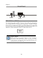
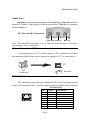
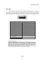
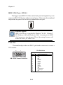
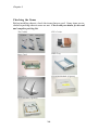
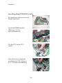
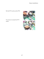
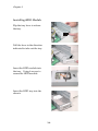
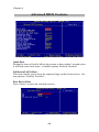
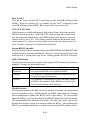
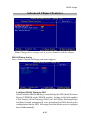
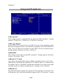
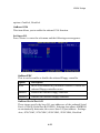
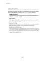
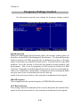
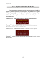
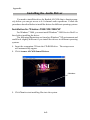
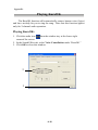
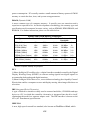
1
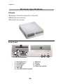
Hermes 845GV Series
MS6243 Barebone
Version 2.2
G52-B6243X6-K01
i
Manual Rev: 2.2
Release Date: Dec. 2002
FCC-B Radio Frequency Interference Statement
This equipment has been tested and found to comply with the limits for a class
B digital device, pursuant to part 15 of the FCC rules. These limits are designed
to provide reasonable protection against harmful interference when the equipment is operated in a commercial environment. This equipment generates, uses
and can radiate radio frequency energy and, if not installed and used in accordance with the instruction manual, may cause harmful interference to radio
communications. Operation of this equipment in a residential area is likely to
cause harmful interference, in which case the user will be required to correct
the interference at his own expense.
Notice 1
The changes or modifications not expressly approved by the party responsible for compliance could void the user’s authority to operate the equipment.
Notice 2
Shielded interface cables and AC. power cord, if any, must be used in order to
comply with the emission limits.
VOIR LA NOTICE D’INSTALLATION AVANT DE RACCORDER AU
RESEAU.
Micro-Star International MS-6243
Tested to comply
with FCC Standard
For Home or Office Use
ii
Copyright Notice
The material in this document is the intellectual property of MICRO-STAR
INTERNATIONAL. We take every care in the preparation of this document,
but no guarantee is given as to the correctness of its contents. Our products
are under continual improvement and we reserve the right to make changes
without notice.
Trademarks
All trademarks are the properties of their respective owners.
AMD, Athlon™, Athlon™ XP, Thoroughbred™, and Duron™ are registered
trademarks of AMD Corporation.
PS/2 and OS®/2 are registered trademarks of International Business Machines
Corporation.
Windows ® 95/98/2000/NT/XP are registered trademarks of Microsoft
Corporation.
Netware® is a registered trademark of Novell, Inc.
Award® is a registered trademark of Phoenix Technologies Ltd.
AMI® is a registered trademark of American Megatrends Inc.
Revision History
Revision
V1.0
V2.0
v2.1
v2.2
Revision History
First release
Changing to
Intel 845 GV+ICH4
Special Edition for Elonex
Replace v2.0
iii
Date
May 2002
Oct. 2002
Dec. 2002
Dec. 2002
Safety Instructions
1.
2.
3.
4.
5.
Always read the safety instructions carefully.
Keep this User’s Manual for future reference.
Keep this equipment away from humidity.
Lay this equipment on a reliable flat surface before setting it up.
The openings on the enclosure are for air convection hence protects the
equipment from overheating. DO NOT COVER THE OPENINGS.
6. Make sure the voltage of the power source and adjust properly 110/220V
before connecting the equipment to the power inlet.
7. Place the power cord such a way that people can not step on it. Do not
place anything over the power cord.
8. Always Unplug the Power Cord before inserting any add-on card or module.
9. All cautions and warnings on the equipment should be noted.
10. Never pour any liquid into the opening that could damage or cause electrical shock.
11. If any of the following situations arises, get the equipment checked by a
service personnel:
z The power cord or plug is damaged.
z Liquid has penetrated into the equipment.
z The equipment has been exposed to moisture.
z The equipment has not work well or you can not get it work according
to User’s Manual.
z The equipment has dropped and damaged.
z The equipment has obvious sign of breakage.
12. DO NOT LEAVE THIS EQUIPMENT IN AN ENVIRONMENT
UNCONDITIONED, STORAGE TEMPERATURE ABOVE 600 C (1400F), IT
MAY DAMAGE THE EQUIPMENT.
CAUTION: Danger of explosion if battery is incorrectly replaced.
Replace only with the same or equivalent type recommended by the
manufacturer.
iv
About This Manual
This manual is written based on the idea to make a brief introduction of MS6243
barebone. It is ideal for the end-users to get a complete understanding about
this model. The advanced users can also get help while studying this book.
This manual contains six sections. Each section mentions the points as follows:
Chapter 1: Getting Started
-- includes barebone specifications, mainboard specifications and
mainboard layout. It is useful for the users to get a basic understanding
of this model.
Chapter 2: Mainboard Setup
-- tells you how to set up the mainboard; includes components
introduction and jumpers setting. It is helpful for the end and
advanced users.
Chapter 3: Chassis Installation
-- tells you how to install the chassis and components. It is useful for
the users who want to set up the system.
Chapter 4: BIOS Setup
--includes the function introduction of BIOS menu. It is ideal for the
advanced users who want to adjust the system.
Appendix: Using 4- or 6- Channel Audio Function
--provides you with the information of 4- or 6- channel audio function
for reference.
Glossary
--provides the definition of technical terms mentioned in this manual.
It is helpful for the end-users to get a clear understanding of technical
terms.
v
Technical Support
If a problem arises with your system and no solution can be
obtained from the user’s manual, please contact your place of
purchase or local distributor. Alternatively, please try the following help resources for further guidance.
Visit the MSI website for FAQ, technical guide, BIOS
updates, driver updates, and other information: http://www.
msi.com.tw/
Contact our technical staff at: [email protected]
vi
CONTENTS
Chapter 1. Introduction ............................................................................ 1-1
Barebone Specifications ....................................................................... 1-2
Mainboard Specifications .................................................................... 1-4
Mainboard Layout ............................................................................... 1-6
Quick Component Guide ...................................................................... 1-7
Chapter 2. Mainboard Setup ..................................................................... 2-1
Central Processing Unit: CPU .............................................................. 2-2
CPU Installation Procedure ........................................................... 2-3
Attaching CPU Cooler ................................................................... 2-4
Memory Installation ............................................................................. 2-5
Introduction to DDR SDRAM ....................................................... 2-5
DDR Module Combination ............................................................ 2-6
Installing DDR Modules ............................................................... 2-6
Power Supply ....................................................................................... 2-7
ATX 20-Pin Power Connector: ATX1 ............................................ 2-7
ATX 12V Power Connector: JPW1 ................................................ 2-7
Front Panel ........................................................................................... 2-8
1394 Port: J1394-2 ......................................................................... 2-8
USB Ports ...................................................................................... 2-9
Audio Port ..................................................................................... 2-9
SPDIF Jack .................................................................................... 2-9
Back Panel .......................................................................................... 2-10
Serial Ports: COM A & COM B ................................................... 2-10
Audio Port ................................................................................... 2-11
AV-out Connector: TV1 ............................................................... 2-11
RJ-45 LAN Jack ........................................................................... 2-11
Parallel Port .................................................................................. 2-12
DVI Port ....................................................................................... 2-13
IEEE 1394 Port: J1394-1 ................................................................ 2-14
vii
VGA Port ..................................................................................... 2-14
USB Ports .................................................................................... 2-15
Mouse Connector ....................................................................... 2-15
Keyboard Connector ................................................................... 2-16
Connectors ......................................................................................... 2-17
Hard Disk Connectors: IDE1 & IDE2 ........................................... 2-17
Front Panel Connector: JFP1 ....................................................... 2-18
CD-In Connector: JCD1 ............................................................... 2-19
Fan Power Connectors: CPUFAN1/SYS_FAN ............................ 2-20
FDD Connector: FDD1 ................................................................ 2-21
TV-Out Connector: JTV1 ............................................................. 2-21
Jumper ................................................................................................ 2-22
Clear CMOS Jumper: JBAT1 ........................................................ 2-22
Slot ..................................................................................................... 2-23
PCI Slot ........................................................................................ 2-23
PCI Interrupt Request Routing .................................................... 2-24
Chapter 3. Chassis Installation ................................................................ 3-1
Overview .............................................................................................. 3-2
Installation Tools ........................................................................... 3-2
Screws ........................................................................................... 3-2
Installation Flowchart .................................................................... 3-3
Checking the items ........................................................................ 3-4
Installation Procedures ........................................................................ 3-5
Chapter 4. AMI® BIOS Setup ................................................................... 4-1
Entering Setup ...................................................................................... 4-2
Selecting the 1st Boot Device ....................................................... 4-2
Control Keys ................................................................................. 4-3
Getting Help .................................................................................. 4-3
The Main Menu ................................................................................... 4-4
Standard CMOS Setup ......................................................................... 4-6
viii
Advanced BIOS Features .................................................................... 4-8
Advanced Chipset Features ............................................................... 4-13
Power Management Features ............................................................. 4-16
PNP/PCI Configurations ..................................................................... 4-19
Integrated Peripherals ........................................................................ 4-22
PC Health Status ................................................................................ 4-25
Frequency/Voltage Control ................................................................ 4-26
Set Supervisor/User Password ........................................................... 4-27
Load Optimal/Fail-Safe Defaults ......................................................... 4-28
Appendix: Using 4- or 6-Channel Audio Function .................................... A-1
Installing the Audio Driver ................................................................. A-2
Using 4-/6- Channel Audio Function .................................................. A-4
Testing the Connected Speakers ......................................................... A-8
Playing KaraOK ................................................................................ A-10
Glossary .................................................................................................... G-1
ix
Introduction
Introduction
1
Congratulations for purchasing MS-6243 barebone. The MS6243 barebone is your best Slim PC choice. Based on the “all-inone” design idea, the MS-6243 provides 2 “1394” ports (option), 6
USB ports, 2 TV-out jacks (option), 1 DVI jack (option) and 1
SPDIF jack. With the fantastic appearance and small form factor,
it can easily be set anywhere in a clean look. The feature packed
platform also gives you a exciting PC experience.
1-1
Chapter 1
Barebone Specifications
Chassis
hDimension: 310mm (H) x 84mm (W) x 345mm (D)
hMinimised screw structure
hDetachable bay housing
Front Panel
1.
2.
3.
4.
5.
6.
Slim Floppy Drive
CD-ROM Drive
Power Switch
Power LED
HDD LED
4-Pin IEEE 1394 Port (option)
1-2
1-2
7. USB Ports
8. MIC-in
9. Line-out
10. SPDIF Jack (optical)
Introduction
Back Panel
1.
2.
3.
4.
5.
6.
7.
8.
9.
S-Video Port (option)
COM A
PCI Slots
COM B
MIC-in
Line-in
Line-out
AV-out (option)
Parallel Port
10.
11.
12.
13.
14.
15.
16.
17.
18.
DVI Port (option)
VGA Port
RJ-45 LAN Jack
USB Ports
PS/2 Mouse
PS/2 Keyboard
6-Pin IEEE1394 Port (option)
Power Jack
Voltage Selector (115/230V)
Power Supply
hPFC
hWattage
hSafety/EMC Compliant
hAC Input Voltage
hDC Output Voltage
hPower Supply Fan
hDimension
: Passive PFC
: 200W max.
: FCC, UL, CUL, BSMI, CB, NEMKO, TUV, CCC
: 100-127/200-240 VAC, Switch Selectable
: 3.3V(14A). 5V(21A), 12V(10A), -12V(0.8A),
5Vsb (2A)
: 80 x 80 x 25mm
: 80 (H) x 120 (W) x 120 (D) mm
Daughter Board
hPCI Riser Card: 1 to 2 slot PCI Riser Card
1-3
Chapter 1
Mainboard Specifications
Model: MS-6557
CPU
h Supports Socket 478 for Intel® Pentium™ 4 processor up to 2.53GHz and
above
Chipset
h Intel® 845GV chipset
- Integrated video accelerator
- Supports 100/133 MHz FSB
- Supports 533 /400 MHz Intel® NetBurst micro-architecture bus
- Supports DDR 200/266 memory.
h Intel® ICH4 chipset
- Hi-Speed USB (USB2.0) controller, 480Mb/sec.
- 2 channel Ultra ATA 100 bus Master IDE controller.
- PCI Master 2.2.
- I/O APIC.
- AC’97 2.2 interface.
- 3 UHCI Host controllers and 1 EHCI Host controller.
Main Memory
h Two 184-pin DDR DIMMs.
h Supports DDR 200/266 memory up to 2GB.
Slot
h One 32-bit PCI bus slot
h Can connect 2 Riser PCI card
On-BoardIDE
h Supports P/O, Bus Master, Ultra DMA 66/100 operation
h Can connect to 2 IDE devices.
On-Board Peripherals
h Rear Panel
- 1 parallel port
- PS2 keyboard + PS2 mouse
- 2 USB ports
- Rear Audio (Mic_in, Line_in, Line_out)
- 1 VGA port
1-4
Introduction
- 1 LAN (RJ45) port
- 1 DVI connector for LCD monitor (Optional)
- 2 TV out connectors: AV out & S-video out (Optional)
- 6-pin 1394 connector (Optional)
- 2 serial ports (On-board x1; Header x 1)
h Front Panel
- 2 audio ports (Headphone-out, Mic_in)
- 4 USB ports
- 1 SPDIF
- 4-pin 1394 connector (Optional)
h Internal Pin-Header
- Intel® standard front panel pin-header
- CPU fan & system fan
- Clear CMOS pin-header
- 2 IDE (ATA66/100)
- 1 standard floppy connector
- 1 on-board COM port pin-header
- Audio (CD-in)
- On-board buzzer
- 1 to 2 PCI riser card
Audio
h AC’97 link controller integrated in ICH4
h RealTek ALC650 6-channel audio
- Compliance w/AC’97 v2.2 spec.
- Meet PC2001 audio performance requirement
Dimension
h320mm (L) x 195mm (W)
Form Factor
h Proprietary (4-layer)
Mounting
h 6 mounting holes.
1-5
1-6
TV1
MS-6557 (V3.X) Mainboard
Bottom:
Line-O ut
Line-In
Mic
Intel
82562EZ
NEC
D72874GC
COM 2
Codec
JCD1
Chr ontel
CH7009A-T
JTV1
Top :
COM A
Bottom:
VGA port
D VI-I port
Top : Parallel Port
T: RJ45 LAN jack
B: USB ports
Top : mouse
Bottom: keyboard
J1394-1
SMSC
LPC 47M133- NC
PCI Slot 1
IDE 2
IDE 1
FDD 1
JBAT1
Intel
845GV
ICH4
BATT
+
DDR 2
DDR 1
CPUFAN 1
BIOS
ATX
Power Supply
SYS _FAN
J1394-2
SPD IF
T:Mic
B:Line Out
U SB3
USB2
JPW1
Chapter 1
Mainboard Layout
Introduction
Quick Component Guide
Component
Function
Reference
Socket 478
Installing CPU
See p. 2-2~2-3
DIMM1 & DIMM2
Installing DIMM modules
See p. 2-5~2-6
ATX Power Supply
Connecting to ATX Power Supply See p. 2-7
IDE1 & IDE2
Connecting to HDD
See p. 2-17
JFP1
Connecting to Front Panel
See p. 2-18
JCD1
Connecting to CD-ROM audio
See p.2-19
CPUFAN/SYS_FAN Connecting to system fan and CPU See p.2-20
fan
FDD1
Connecting to FDD
JTV1
Connecting to TV or video device See p. 2-21
JBAT1
Setting clear CMOS
See p. 2-22
PCI Slot1
Connecting to PCI card
See p. 2-23
1-7
See p. 2-21
Mainboard Setup
Mainboard Setup
2
This chapter provides you with the information about hardware setup procedures for MS-6557 mainboard. While doing the
installation, be careful in holding the components and follow the
installation procedures. For some components, if you install in the
wrong orientation, the components will not work properly.
Use a grounded wrist strap before handling computer
components. Static electricity may damage the components.
2-1
Chapter 2
Central Processing Unit: CPU
The mainboard supports Intel® PentiumTM 4 processors (Willimate
478 and Northwood 478). The mainboard uses a CPU socket called Socket 478
for easy CPU installation. While installing the CPU, make sure the CPU has a
heat sink and a cooling fan attached on the top to prevent overheating. If you
do not find the heat sink and cooling fan, contact your dealer or purchase them
before installing the CPU.
Overheating
Overheating will seriously damage the CPU and system, always make sure the cooling fan can work properly to protect
the CPU from overheating.
Replacing the CPU
While replacing the CPU, always turn off the ATX power supply or unplug the power supply’s power cord from grounded
outlet first to ensure the safety of CPU.
2-2
Mainboard Setup
CPU Installation Procedures
1. Turn off the power and unplug
the power cord before installing the CPU.
2. Pull the lever sideways away
from the socket. Make sure
to raise the lever up to a 90degree angle.
3. Look for the gold arrow. The
gold arrow should point towards the lever pivot. The
CPU can only fit in the correct
orientation.
4. If the CPU is correctly
installed, the pins should be
completely embedded into the
socket.
Open Lever
Sliding
Plate
90 degree
Gold arrow
Correct CPU placement
Gold arrow
Any violation of the correct
installation procedures may
cause permanent damages to
your mainboard.
Gold arrow
5. Press the CPU down firmly into
the socket and close the lever.
As the CPU is likely to move
while the lever is being
closed, always close the lever with your fingers pressing tightly on top of the CPU
to make sure the CPU is properly and completely embedded into the socket.
Press down
the CPU
2-3
O
Incorrect CPU placement
X
Close
Lever
Chapter 2
Attaching CPU Cooler
The CPU cooler included in the packing is designed specially for MS6243 barebone. It is different from other CPU cooler of PentiumTM4. See the
follows for the features:
z
z
z
z
z
Copper Material
The heatsink is made of copper that has better heat-disseminating effect.
Shockproof Effect
The cooler has good shockproof effect through the mechanical combi
nation design of CPU fan and heatsink.
Small Size
Contrast to normal CPU cooler, the small size takes up less space.
Special Fan Design
The CPU fan has ball bearing solution. The reliability is better than
sleeve solution. It is suitable for Slim PC.
High Density Fan Fins
The CPU cooler has high density fan fins than normal CPU cooler. It is
ideal for heat disseminating.
1. Put the CPU cooler on the CPU.
2. Use 4 screws to secure
* The four screws of CPU cooler
are built-in.
the CPU cooler.
* The front part of screw is designed for shockproof. While
securing the cooler, the front
part of screw can not be embedded into the hole
completely.
shockproof design
2-4
Mainboard Setup
Memory Installation
Intel
845GV
The mainboard provides two sockets for 184-pin DDR SDRAM DIMM
(Double In-Line Memory Module) and supports the memory size up to 2 GB.
You can install PC2100/DDR266 or PC1600/DDR200 modules into the DDR
DIMM slots.
DDR1 DDR2
Introduction to DDR SDRAM
DDR (Double Data Rate) SDRAM is similar to conventional SDRAM,
but doubles the rate by transferring data twice per cycle. It uses 2.5 volts as
opposed to 3.3 volts used in SDR SDRAM, and requires 184-pin DIMM modules rather than 168-pin DIMM modules used by SDR SDRAM. Two types of
DDR are available at the time of writing: PC1600 & PC2100. PC1600 DDR SDRAM
running at 100MHz will produce about 1.6GB/s memory bandwidth. PC2100
running at 133MHz will produce 2.1GB/s memory bandwidth. High memory
bandwidth makes DDR an ideal solution for high performance PC, workstations and servers.
2-5
Chapter 2
DDR Module Combination
Install at least one DIMM module into the slots. Memory modules can
be installed into the slots in any order. You can install either single or doublesided modules to meet your need.
Slot
Combination
1
2
DDR 1
S/D
S/D
DDR 2
S/D
S/D
Total Memory
64MB~2GB
64MB~2GB
S (Single Side): 64MB ~ 512MB
D (Double Side): 128MB ~ 1GB
Installing DDR Modules
1. The DDR DIMM has only one notch on the center of module. The module
will only fit in the right orientation.
2. Insert the DIMM memory module vertically into the DIMM slot. Then
push it in.
notch
Volt
3. The plastic clip at each side of the DIMM slot will automatically close.
2-6
Mainboard Setup
Power Supply
ATX 20-Pin Power Connector: ATX1
This connector allows you to connect to an ATX power supply. To
connect to the ATX power supply, make sure the plug of the power supply is
inserted in the proper orientation and the pins are aligned. Then push down
the power supply firmly into the connector. The power connector supports
instant power on function which means that system will boot up immediately
when the power supply connector is inserted on the board.
ATX 12V Power Connector: JPW1
This 12V power connector is used to provide power to the CPU.
JPW1
3
4
1
2
ATX1
11
10
1
Intel
845GV
20
ATX1 Pin Definition
JPW1 Pin Definition
PIN
SIGNAL
1
2
3
4
GND
GND
12V
12V
2-7
PIN
SIGNAL
PIN
SIGNAL
1
2
3
4
5
6
7
8
9
10
3.3V
3.3V
GND
5V
GND
5V
GND
PW_OK
5V_SB
12V
11
12
13
14
15
16
17
18
19
20
3.3V
-12V
GND
PS_ON
GND
GND
GND
-5V
5V
5V
Chapter 2
Front Panel
Audio Port
SPDIF Jack
J1394-2
USB Ports
IEEE 1394 Port: J1394-2
The mainboard provides two IEEE 1394 ports. This smaller one is designed for
you to connect the IEEE 1394 device with external power. The IEEE 1394 highspeed serial bus complements USB by providing enhanced PC connectivity
for a wide range of devices, including consumer electronics audio/video (A/V)
appliances, storage peripherals, other PCs, and portable devices.
Software Support
IEEE 1394 Driver is provided by Windows® 98 SE, Windows®
XP, Windows® ME and Windows® 2000. Just plug in the IEEE
1394 connector into the port. These Operating Systems will
install the driver for IEEE 1394.
2-8
Mainboard Setup
USB Ports
The mainboard provides a UHCI (Universal Host Controller Interface)
Universal Serial Bus root for attaching USB devices such as keyboard, mouse
or other USB-compatible devices. You can plug the USB device directly into
these connectors.
USB Port Description
PIN
1
2
3
4
5
6
7
8
SIGNAL
VCC
-Data 0
+Data0
GND
VCC
-Data 1
+Data 1
GND
DESCRIPTION
+5V
Negative Data Channel 0
Positive Data Channel 0
Ground
+5V
Negative Data Channel 1
Positive Data Channel 1
Ground
Audio Port
This allows you to connect the front audio device
MIC-in
Line-Out
SPDIF Jack
The connector allows you to connect to Sony & Philips Digital Interface (SPDIF), developed jointly by the Sony and Philips corporations . A
standard audio file transfer format, SPDIF allows the transfer of digital audio
signals from one device to another without having to be converted first to an
analog format.
2-9
Chapter 2
Back Panel
The Rear Panel provides the following connectors:
Mouse
LAN Jack
J1394-1 Keyboard USB Ports
COM A
Parallel Port
DVI Port
VGA Port
TV1
Line-in MIC -in
Line-out
Serial Ports: COM A & COM B
The mainboard offers two 9-pin male DIN connectors as serial port COM
A & COM B (COM B is the header COM2 on the board). The ports are 16550A
high speed communication ports that send/receive 16 bytes FIFOs. You can
attach a serial mouse or other serial devices directly to the connectors.
1 2 3 4 5
Pin Definition
6 7 8 9
9-Pin Male DIN Connector
8
6
4
2
9
7
5
3
1
PIN
SIGNAL
DESCRIPTION
1
2
3
4
5
6
7
8
9
DCD
SIN
SOUT
DTR
GND
DSR
RTS
CTS
RI
Data Carry Detect
Serial In or Receive Data
Serial Out or Transmit Data
Data Terminal Ready
Ground
Data Set Ready
Request To Send
Clear To Send
Ring Indicate
COM2 (COM B)
2-10
Mainboard Setup
Audio Port
Line Out is a connector for Speakers or Headphones. Line In is used for
external CD player, Tape player, or other audio devices. Mic-in is a connector
for microphones.
1/8” Stereo Audio Connectors
Line Out Line In
MIC-in
Note: The mainboard supports 4- or 6- channel audio function. For more
information, refer to Appendix.
AV-out Connector: TV1
You can connect to a TV or video device to TV1 connector for videoout function which allows you to output the image to a TV or video device.
TV
TV1
Connector
Projector
RJ45 LAN Jack
The mainboard provides one standard RJ-45 jack for connection to
Local Area Network (LAN). You can connect a network cable to the LAN jack.
Pin Definition
PIN
SIGNAL
DESCRIPTION
1
TDP
Transmit Differential Pair
2
TDN
Transmit Differential Pair
3
RDP
Receive Differential Pair
4
NC
Not Used
5
NC
Not Used
6
RDN
Receive Differential Pair
7
NC
Not Used
8
NC
Not Used
2-11
Chapter 2
Parallel Port
The mainboard provides a 25-pin female centronic connector as LPT. A
parallel port is a standard printer port that supports Enhanced Parallel Port
(EPP) and Extended Capabilities Parallel Port (ECP) mode.
13
1
14
25
Pin Definition
PIN
SIGNAL
DESCRIPTION
1
2
3
4
5
6
7
8
9
10
11
12
13
14
15
16
17
18
19
20
21
22
23
24
25
STROBE
DATA0
DATA1
DATA2
DATA3
DATA4
DATA5
DATA6
DATA7
ACK#
BUSY
PE
SELECT
AUTO FEED#
ERR#
INIT#
SLIN#
GND
GND
GND
GND
GND
GND
GND
GND
Strobe
Data0
Data1
Data2
Data3
Data4
Data5
Data6
Data7
Acknowledge
Busy
Paper End
Select
Automatic Feed
Error
Initialize Printer
Select In
Ground
Ground
Ground
Ground
Ground
Ground
Ground
Ground
2-12
Mainboard Setup
DVI Port
The mainboard provides a DVI (Digital Visual Interface) connector
which allows you to connect an LCD monitor. The DVI connector provides a
high-speed digital interconnection between the computer and its display device.
1
8 C1 C2
17
24
C3
DVI-I Connector
Pin
1
2
3
4
5
6
7
8
9
10
11
12
C1
C2
C3
Signal Assignment
T.M.D.S.* Data2T.M.D.S. Data2+
T.M.D.S. Data2/4 Shield
T.M.D.S. Data4T.M.D.S. Data4+
DDC Clock
DDC Data
N/C
T.M.D.S. Data1T.M.D.S. Data1+
T.M.D.S. Data1/3 Shield
T.M.D.S. Data3-
Pin
13
14
15
16
17
18
19
20
21
22
23
24
Signal Assignment
T.M.D.S. Data3+
+5V
GND (for +5V)
Hot Plug Detect
T.M.D.S. Data0T.M.D.S. Data0+
T.M.D.S. Data0/5 Shield
T.M.D.S. Data5T.M.D.S. Data5+
T.M.D.S. Clock Shield
T.M.D.S. Clock+
T.M.D.S. Clock-
Analog Red
Analog Green
Analog Blue
*T.M.D.S. Technology
The graphics data sent to the digital monitor use Transition Minimized
Differential Signaling (T.M.D.S.) technology. TMDS uses an encoding
algorithm to 8-bit of data into a 10-bit transition minimized, DC balanced
character, which are transition-minimized to reduce EMI with copper
cables and DC-balanced for transmission over fiber optic cables. The
TMDS algorithm also provides robust clock recovery for greater skew
tolerance with longer cables or low cost short cables.
2-13
Chapter 2
IEEE 1394 Port: J1394-1
The bigger 6-pin IEEE 1394 Port on the back panel is designed for you to
connect to IEEE 1394 devices without external power. That means the mainboard
can provide the power for the devices connected to this port.
Software Support
IEEE 1394 Driver is provided by Windows® 98 SE, Windows®
XP, Windows® ME and Windows® 2000. Just plug in the IEEE
1394 connector into the port. These Operating Systems will
install the driver for IEEE 1394.
VGA Port
The mainboard provides one DB 15-pin female connector to connect a
VGA monitor.
5
1
Pin Definition
Analog Video Display Connector (DB-15S)
15
11
DB 15-Pin Female Connector
PIN
SIGNAL DESCRIPTION
1
2
3
4
5
6
7
8
9
10
11
12
13
14
15
Red
Green
Blue
Not used
Ground
Ground
Ground
Ground
Power
Ground
Not used
SDA
Horizontal Sync
Vertical Sync
SCL
2-14
Mainboard Setup
USB Ports
The mainboard provides a UHCI (Universal Host Controller Interface)
Universal Serial Bus root for attaching USB devices such as keyboard, mouse
or other USB-compatible devices. You can plug the USB device directly into
the connector.
USB Port Description
1
2
3
4
5
6
7
8
PIN
1
2
3
4
5
6
7
8
USB Ports
SIGNAL
VCC
-Data 0
+Data0
GND
VCC
-Data 1
+Data 1
GND
DESCRIPTION
+5V
Negative Data Channel 0
Positive Data Channel 0
Ground
+5V
Negative Data Channel 1
Positive Data Channel 1
Ground
Mouse Connector
The mainboard provides a standard PS/2® mouse mini DIN connector
for attaching a PS/2® mouse. You can plug a PS/2® mouse directly into this
connector.
Pin Definition
6
5
3
4
2
1
PS/2 Mouse (6-pin Female)
PIN
SIGNAL
DESCRIPTION
1
2
3
4
5
6
Mouse DATA
NC
GND
VCC
Mouse Clock
NC
Mouse DATA
No connection
Ground
+5V
Mouse clock
No connection
2-15
Chapter 2
Keyboard Connector
The mainboard provides a standard PS/2® keyboard mini DIN connector for attaching a PS/2® keyboard. You can plug a PS/2® keyboard directly into
this connector.
Pin Definition
6
5
3
4
2
1
PS/2 Keyboard (6-pin Female)
PIN
1
2
3
4
5
6
2-16
SIGNAL
Keyboard DATA
NC
GND
VCC
Keyboard Clock
NC
DESCRIPTION
Keyboard DATA
No connection
Ground
+5V
Keyboard clock
No connection
Mainboard Setup
Connectors
.
Hard Disk Connectors: IDE1 & IDE2
The mainboard has a 32-bit Enhanced PCI IDE and Ultra DMA 33/66/100
controller that provides PIO mode 0~4, Bus Master, and Ultra DMA/33/66/100
function. The two connectors on the motherboard allows you to connect to
only two IDE devices. As the MS-6243 Barebone is a slim PC, there is no extra
space for you to connect two more IDE devices. Also, please be careful the
two connectors can only connect to the specific IDE devices as below:
IDE1 (Primary IDE Connector)
The hard drive should always be connected to IDE1.
Intel
845GV
IDE 2
IDE 1
IDE2 (Secondary IDE Connector)
IDE2 can only connect a CD-ROM drive.
2-17
Chapter 2
Front Panel Connector: JFP1
I nte l
84 5GV
The mainboard provides one front panel connector for you to connect
to the front panel switches and LEDs. JFP1 is compliant with Intel® Front Panel
I/O Connectivity Design Guide.
Power Power
LED
Switch
JFP1
2
1
10
9
HDD Reset
LED Switch
JFP1 Pin Definition
PIN
SIGNAL
DESCRIPTION
1
2
3
4
5
6
7
8
9
HD_LED_P
FP PWR/SLP
HD_LED_N
FP PWR/SLP
RST_SW_N
PWR_SW_P
RST_SW_P
PWR_SW_N
RSVD_DNU
Hard disk LED pull-up
MSG LED pull-up
Hard disk active LED
MSG LED pull-up
Reset Switch low reference pull-down to GND
Power Switch high reference pull-up
Reset Switch high reference pull-up
Power Switch low reference pull-down to GND
Reserved. Do not use.
2-18
Mainboard Setup
CD-In Connector: JCD1
2-19
JCD1
L GND R
I nte l
845GV
The connector is for CD-ROM audio connector.
Chapter 2
Fan Power Connectors: CPUFAN1/SYS_FAN
The CPUFAN1 (CPU fan) & SYS_FAN (system fan) support system cooling fans with +12V that is controlled by PWM. When connecting the wire to
the three-pin head connectors, always note that the red wire is the positive and
should be connected to the +12V (that is controlled by PWM), the black wire is
Ground and should be connected to GND. If the mainboard has a System
Hardware Monitor chipset on-board, you must use a specially designed fan
with speed sensor to take advantage of the CPU fan control.
SYS_FAN
GND
+12V
SENSOR
CPUFAN1
I n te l
845GV
GND
+12V
SENSOR
1. Always consult the vendor for proper CPU cooling fan.
2. CPU Fan supports the fan control. You can install the PC
Alert utility that will automatically control the CPU Fan
speed according to the actual CPU temperature.
2-20
Mainboard Setup
FDD Connector:FDD1
The mainboard provides you with a standard floppy disk drive connector that supports 360K, 720K, 1.2M, 1.44M and 2.88M floppy disk types
In te l
84 5GV
FDD1
TV-Out Connector:JTV1
In te l
84 5GV
The mainboard provides an onboard TV-out connector for you to connect to a TV or video device.
JTV1
2-21
Chapter 2
Jumper
The motherboard provides one jumper for you to set the computer’s
function. This section will explain how to change your motherboard’s function
through the use of the jumper.
Clear CMOS Jumper:JBAT1
There is a CMOS RAM on board that has a power supply from external
battery to keep the data of system configuration. With the CMOS RAM, the
system can automatically boot OS every time it is turned on. That battery has
long life time for at least 5 years. If you want to clear the system configuration,
use the JBAT1 (Clear CMOS Jumper ) to clear data. Follow the instructions
below to clear the data:
I n te l
845GV
1
JBAT1
3
3
1
1
Keep CMOS
Clear CMOS
You can clear CMOS by shorting 2-3 pin while the system is
off. Then return to 1-2 pin position. Avoid clearing the
CMOS while the system is on; it will damage the
mainboard.
2-22
Mainboard Setup
Slot
I nte l
845GV
The mainboard provides one 32-bit Master PCI bus slot.
PCI Slot 1
PCI Riser Card
PCI Slot
The PCI slot allows you to insert PCI Riser Card. The PCI Riser Card is
included in the MS-6243 Barebone. The Riser Card allows you to insert two
expansion cards. You can insert any type of PCI cards to meet your needs.
When adding or removing expansion cards, make sure that you unplug
the power supply first. Meanwhile, read the documentation for the expansion
card to make any necessary hardware or software settings.
2-23
Chapter 2
PCI Interrupt Request Routing
The IRQ, abbreviation of interrupt request line and pronounced I-R-Q,
are hardware lines over which devices can send interrupt signals to the
microprocessor. The “AGP/PCI” IRQ pins are typically connected to the PCI
bus INT A# ~ INT D# pins as follows:
Order 1 Order 2 Order 3 Order 4
1394
INT E#
PCI Slot
INT B#
INT C# INT D#
2-24
INT A#
Chassis Installation
Chassis Installation
3
This chapter provides you with the installation procedures
of the MS-6243 chassis. It is useful for you to read the information
of mainboard setup before assembling the whole system.
3-1
Chapter 3
Overview
The built-in MS-6557 mainboard is designed for MS-6243 barebone only.
Except MS-6557 mainboard, the built-in components of MS-6243 barebone
include power supply and PCI riser card. In this chapter we’ll show you how to
install CPU, FDD, HDD, CD-ROM and CPU Cooler.
Installation Tools
Screw Driver
Pliers
Forceps
Rubber gloves
Screws
Four types of screws are provided by MS-6243 Barebone: Roundheaded screws, Hexagonal screw with washer and two kinds of Flatheaded screws. The screws that have been installed in the barebone
are not listed.
Round-headed screw: This type of screw is used to attach
the HDD to the chassis.
Hexagonal screw with washer: The screw is used to fasten
the mainboard, cover, and CD-ROM to the chassis.
Flat-headed screw: This type of screw is used to fasten
the Standard FDD to the Front Panel Bezel.
3-2
Chassis Installation
Installation Flowchart
START
Remove Chassis Cover
Install HDD Module
Remove Front Panel Bezel
Install FDD Module
Install DIMM Module
Install CD-ROM Module
Install CPU
Replace Front Panel Bezel
Install CPU Cooler
Replace Cover
FINISH
3-3
Chapter 3
Checking the Items
Before installing chassis, check the items that are used. Some items are included in packing whereas some are not. Check with your dealer for the real
and complete packing list.
The Cables
CD-ROM
CPU Cooler
HDD
FDD (Option)
Riser Card
HDD Tray
Footstand
CD-ROM Module (Option)
FDD Module (Option)
3-4
Chassis Installation
Installation Procedures
Removing Cover & Front Panel Bezel
Remove the two screws on
the cover.
Take out the cover.
Use your two hands to press
the place indicated.
Remove the Front Panel Bezel.
3-5
Chapter 3
Installing Ram/CPU/CPU Cooler
The barebone without cover and
Front Panel Bezel.
Install the DIMM module.
(Refer to p. 2-6 for
more information.)
Put the CPU on the CPU
socket.
Close the lever to finish the
installation of CPU. (Refer to
p. 2- 3 for more information.)
3-6
Chassis Installation
Put the CPU cooler on the CPU.
Use screws to secure the CPU
cooler.
3-7
Chapter 3
Installing HDD Module
Flip the tray lever to release
the tray.
Pull the lever in the direction
indicated to take out the tray.
Insert the HDD module into
the tray. Using 4 screws to
secure the HDD module.
Insert the HDD tray into the
chassis.
3-8
Chassis Installation
Connect the cables (including
HDD cable and power cord).
Power Cord
Push the lever back into place.
Finish the HDD installation.
3-9
HDD Cable
Chapter 3
Installing FDD
Flip the place indicated to
take out the bracket of Front
Panel Bezel.
Reverse the Front Panel
Bezel.
Insert the FDD module into
the Front Panel Bezel.
Using screws to secure the
FDD module.
3-10
Chassis Installation
Installing CD-ROM
Insert the CD-ROM into the
Front Panel Bezel.
Secure the CD-ROM using
the two screws on the top.
Note: There are three holes: I, E
and S. Please insert the screw into
the third hole “S”.
Secure the CD-ROM using the
two screws on the right side.
Note: There are three holes: I, E and
S. Please insert the screw into the
third hole “S”.
Finish the FDD & CD-ROM
installation.
3-11
Chapter 3
Connecting the Cables; Replacing Bezel & Cover
Connect the System Fan cable.
Replace the Front Panel Bezel.
Connect the LED indicator
cable.
Connect the CD-ROM cable.
3-12
Chassis Installation
Connect the FDD cable.
Use screws to secure the
Front Panel Bezel.
Replace the cover and use screws
to secure it
Place the barebone on the
Footstand.
3-13
BIOS Setup
AMI® BIOS Setup
4
This chapter provides information on the BIOS Setup program and allows you to configure the system for optimum use.
You may need to run the Setup program when:
An error message appears on the screen during the system
booting up, and requests you to run SETUP.
You want to change the default settings for customized
features.
4-1
Chapter 4
Entering Setup
Power on the computer and the system will start POST (Power On Self
Test) process. When the message below appears on the screen, press <DEL>
key to enter Setup.
DEL:Setup
F12:Network boot
TAB:Logo
If the message disappears before you respond and you still wish to enter
Setup, restart the system by turning it OFF and On or pressing the RESET
button. You may also restart the system by simultaneously pressing <Ctrl>,
<Alt>, and <Delete> keys.
Selecting the First Boot Device
You are allowed to select the 1st boot device without entering the BIOS
setup utility by pressing <F11>. When the same message as listed above
appears on the screen, press <F11> to trigger the boot menu.
The POST messages might pass by too quickly for you to respond in
time. If so, restart the system and press <F11> after around 2 or 3 seconds to
activate the boot menu similar to the following.
Select First Boot Device
Floppy
IDE-0
CD-ROM
: 1st Floppy
: IBM-DTLA-307038
: ATAPI CD-ROM DRIVE 40X M
[Up/Dn] Select
[RETURN] Boot
[ESC] cancel
The boot menu will list all the bootable devices. Select the one you want
to boot from by using arrow keys and then pressing <Enter>. The system will
boot from the selected device. The selection will not make changes to the
settings in the BIOS setup utility, so next time when you power on the system,
it will still use the original first boot device to boot up.
4-2
BIOS Setup
Control Keys
< >
Move to the previous item
< >
Move to the next item
< >
Move to the item on the left-hand side
< >
Move to the item on the right-hand side
<Enter> Select the item
Jumps to the Exit menu or returns to the main menu from a
<Esc>
submenu
<+/PU>
Increase the numeric value or make changes
<-/PD>
Decrease the numeric value or make changes
<F1>
General help, only for Status Page Setup Menu and Option
Page Setup Menu
<F6>
Load the default CMOS value from Fail-Safe default table, only
for Option Page Setup Menu
<F7>
Load Optimized defaults
<F10>
Save all the CMOS changes and exit
Getting Help
After entering the Setup utility, the first screen you see is the Main Menu.
Main Menu
The main menu displays the setup categories the BIOS supplies. You can use
the arrow keys ( ↑↓ ) to select the item. The on-line description for the selected
setup category is displayed at the bottom of the screen.
Default Settings
The BIOS setup program contains two kinds of default settings: the BIOS
Setup and Optimal defaults. BIOS Setup defaults provide stable performance
settings for all devices and the system, while High Performance defaults provide the best system performance but may affect the system stability.
4-3
Chapter 4
The Main Menu
Once you enter AMIBIOS EASY SETUP UTILITY, the Main Menu will
appear on the screen. The Main Menu displays twelve configurative functions and two exit choices. Use arrow keys to move among the items and press
<Enter> to enter the sub-menu.
Standard CMOS Features
Use this menu for basic system configurations, such as time, date etc.
Advanced BIOS Features
Use this menu to setup the items of AMI® special enhanced features.
Advanced Chipset Features
Use this menu to change the values in the chipset registers and optimize your
system’s performance.
Power Management Features
Use this menu to specify your settings for power management.
PNP/PCI Configurations
This entry appears if your system supports PnP/PCI.
Integrated Peripherals
Use this menu to specify your settings for integrated peripherals.
4-4
BIOS Setup
PC Health Status
This entry shows your PC health status.
Frequency/Voltage Control
Use this menu to specify your settings for frequency/voltage control.
Set Supervisor Password
Use this menu to set Supervisor Password.
Set User Password
Use this menu to set User Password.
Load Fail Safe Defaults
Use this menu to load factory default settings into the BIOS for stable system
performance operations.
Load Optimal Defaults
Use this menu to load the BIOS values for the best system performance, but
the system stability may be affected.
Save & Exit Setup
Save changes to CMOS and exit setup.
Exit Without Saving
Abandon all changes and exit setup.
4-5
Chapter 4
Standard CMOS Features
The items inside STANDARD CMOS FEATURES menu are divided
into 9 categories. Each category includes none, one or more setup items. Use
the arrow keys to highlight the item you want to modify and use the <PgUp> or
<PgDn> keys to switch to the value you prefer.
System Date
This allows you to set the system to the date that you want (usually the current
date). The format is <day><month> <date> <year>.
day
Day of the week, from Sun to Sat, determined by
BIOS. Read-only.
month
The month from Jan. through Dec.
date
The date from 1 to 31 can be keyed by numeric
function keys.
year
The year can be adjusted by users.
System Time
This allows you to set the system time that you want (usually the current time).
The time format is <hour> <minute> <second>.
4-6
BIOS Setup
Primary/Secondary IDE Master/Slave
Press PgUp/<+> or PgDn/<-> to select the hard disk drive type. The specification of hard disk drive will show up on the right hand according to your selection.
TYPE
CYL
HD
WPCOM
SEC
SIZE
Type of the device.
Number of cylinders.
Number of heads.
Write precompensation.
Number of sectors.
Capacity of the device.
Floppy Drive A:/B:
This item allows you to set the type of floppy drives installed. Available
options: Not Installed, 360 KB 5¼, 1.2 MB 5¼, 720 KB 3½, 1.44 MB 3½, 2.88
MB 3½.
Boot Sector Virus Protection
The item is to set the Virus Warning feature for IDE Hard Disk boot sector
protection. When Enabled, BIOS will issue a virus warning message and beep
if a write to the boot sector or the partition table of the HDD is attempted.
Setting options: Disabled, Enabled.
Note: This feature only protects the boot sector, not the whole hard disk.
4-7
Chapter 4
Advanced BIOS Features
Quick Boot
Setting the item to Enabled allows the system to boot within 5 seconds since
it will skip some check items. Available options: Enabled, Disabled.
Full Screen LOGO Show
This item enables you to show the company logo on the bootup screen. Setting options: Enabled, Disabled.
Boot Device Select
Press <Enter> to enter the sub-menu screen.
4-8
BIOS Setup
1st/2nd/3rd
The items allow you to set the sequence of boot devices where AMIBIOS
attempts to load the operating system. The settings are:
IDE-0
The system will boot from the first HDD.
IDE-1
The system will boot from the second HDD.
IDE-2
The system will boot from the third HDD.
IDE-3
The system will boot from the fourth HDD.
Floppy
The system will boot from floppy drive.
ARMD-FDD
The system will boot from any ARMD device,
such as LS-120 or ZIP drive, that functions as a
floppy drive.
ARMD-HDD
The system will boot from ARMD device, such as
MO or ZIP drive, that functions as hard disk drive.
CD-ROM
The system will boot from the CD-ROM.
Legacy SCSI
The system will boot from the SCSI.
Legacy NETWORK The system will boot from the Network drive.
BBS-0
The system will boot from the first BBS (BIOS
Boot Specification) compliant device.
BBS-1
The system will boot from the second BBS (BIOS
Boot Specification) compliant device.
BBS-2
The system will boot from the third BBS (BIOS
Boot Specification) compliant device.
BBS-3
The system will boot from the fourth BBS (BIOS
Boot Specification) compliant device.
Disabled
Disable this sequence.
Available settings for “1st/2nd/3rd” boot device vary depending on the bootable devices you have installed. For
example, if you did not install a floppy drive, the setting
“Floppy” does not show up.
Try Other Boot Devices
Setting the option to Yes allows the system to try to boot from other
devices if the system fails to boot from the 1st/2nd/3rd boot device.
4-9
Chapter 4
S. .M.A.R.T. for Hard Disks
This allows you to activate the S.M.A.R.T. (Self-Monitoring Analysis & Reporting Technology) capability for the hard disks. S.M.A.R.T is a utility that
monitors your disk status to predict hard disk failure. This gives you an
opportunity to move data from a hard disk that is going to fail to a safe place
before the hard disk becomes offline. Settings: Enabled, Disabled.
BootUp Num-Lock
This item is to set the Num Lock status when the system is powered on.
Setting to On will turn on the Num Lock key when the system is powered on.
Setting to Off will allow end users to use the arrow keys on the numeric keypad.
Setting options: On, Off.
Floppy Drive Swap
Setting to Enabled will swap floppy drives A: and B:.
Floppy Drive Seek
This setting causes the BIOS to search for floppy disk drives at boot time.
When enabled, the BIOS will activate the floppy disk drives during the boot
process: the drive activity light will come on and the head will move back and
forth once. First A: will be done and then B: if it exists. Setting options:
Disabled, Enabled.
Halt on Keyboard Error
When enabled, the system will stop POST process if the keyboard is not
connected. When disabled, the system will show Error message in POST
process while the keyboard is not connected.
Password Check
This specifies the type of AMIBIOS password protection that is implemented.
Setting options are described below.
Option
Description
Setup
The password prompt appears only when end users try to run
Setup.
Always
A password prompt appears every time when the computer is
powered on or when end users try to run Setup.
4-10
BIOS Setup
Boot To OS/2
This allows you to run the OS/2® operating system with DRAM larger than
64MB. When you choose No, you cannot run the OS/2® operating system
with DRAM larger than 64MB. But it is possible if you choose Yes.
CPU L1 & L2 Cache
Cache memory is additional memory that is much faster than conventional
DRAM (system memory). When the CPU requests data, the system transfers the requested data from the main DRAM into cache memory, for even
faster access by the CPU. This setting enables/disables the internal cache
(also known as L1 or level 1 cache) and external cache (also known as L2 or
level 2 cache). Settings are: Enabled and Disabled.
System BIOS Cacheable
Selecting Enabled allows caching of the system BIOS ROM at F0000h-FFFFFh,
resulting in better system performance. However, if any program writes to this
memory area, a system error may result. Setting options: Enabled, Disabled.
C000, 32k Shadow
This item specifies how the contents of the adapter ROM named in the item are
handled. Settings are described below:
Option
Description
Disabled
Enabled
Cached
The specified ROM is not copied to RAM.
The contents of specified ROM are copied to RAM
for faster system performance.
The contents of specified ROM are not only copied
to RAM, the contents of the ROM area can be written to and read from cache memory.
Flash Protection
This function protects the BIOS from accidental corruption by unauthorized
users or computer viruses. When enabled, the BIOS’s data cannot be changed
when attempting to update the BIOS with a Flash utility. To successfully
update the BIOS, you’ll need to disable this BIOS Flash Write Control function.
You should enable this function at all times. The only time when you need to
disable the function is when you want to update the BIOS. After updating the
BIOS, you should immediately re-enable it to protect the BIOS against viruses.
4-11
Chapter 4
Settings: Enabled, Disabled.
MPS Revision
This field allows you to select which MPS (Multi-Processor Specification)
version to be used for the operating system. You need to select the MPS
version supported by your operating system. To find out which version to
use, consult the vendor of your operating system. Options: 1.4, 1.1.
4-12
BIOS Setup
Advanced Chipset Features
Note: Change these settings only if you are familiar with the chipset.
DRAM Timing Setting
Press <Enter> and the following sub-menu appears.
Configure DRAM Timing by SPD
Selects whether DRAM timing is controlled by the SPD (Serial Presence
Detect) EEPROM on the DRAM module. Setting to Enabled enables
CAS# Latency, RAS# Precharge, RAS# to CAS# Delay, Precharge Delay
and Burst Length automatically to be determined by BIOS based on the
configurations on the SPD. Selecting Disabled allows users to configure
these fields manually.
4-13
Chapter 4
CAS# Latency
The field controls the CAS latency, which determines the timing delay before SDRAM starts a read command after receiving it. Setting
options: 2 Clocks and 3 Clocks. 2 Clocks increases system performance while 3Clocks provides more stable system performance.
RAS# Precharge
This item controls the number of cycles for Row Address Strobe
(RAS) to be allowed to precharge. If insufficient time is allowed for
the RAS to accumulate its charge before DRAM refresh, refresh
may be incomplete and DRAM may fail to retain data. This item
applies only when synchronous DRAM is installed in the system.
Available settings: 2 Clocks, 3 Clocks.
RAS# to CAS# Delay
This field allows you to set the number of cycles for a timing delay
between the CAS and RAS strobe signals, used when DRAM is
written to, read from or refreshed. Fast speed offers faster performance while slow speed offers more stable performance. Settings: 3
Clocks, 2 Clocks.
Precharge Delay
The field specifies the idle cycles before precharging an idle bank.
Settings: 7 Clocks, 6 Clocks, 5 Clocks.
Burst Length
This setting allows you to set the size of Burst-Length for DRAM.
Bursting feature is a technique that DRAM itself predicts the
address of the next memory location to be accessed after the first
address is accessed. To use the feature, you need to define the
burst length, which is the actual length of burst plus the starting
address and allows internal address counter to properly generate
the next memory location. The bigger the size, the faster the
DRAM performance. Settings: 4, 8 (QW).
4-14
BIOS Setup
AGP Aperture Size
This setting controls just how much system RAM can be allocated to AGP for
video purposes. The aperture is a portion of the PCI memory address range
dedicated to graphics memory address space. Host cycles that hit the aperture
range are forwarded to the AGP without any translation. The option allows the
selection of an aperture size of 4MB, 8MB, 16MB, 32MB, 64MB, 128MB, and
256 MB.
Internal Graphics Mode Select
The field specifies the size of system memory allocated for video memory.
Settings: 512KB, 1MB, 8MB, Disabled.
4-15
Chapter 4
Power Management Features
ACPI Standby State
This item specifies the power saving modes for ACPI function. Options are:
S1/POS
The S1 sleep mode is a low power state. In this state, no
system context is lost (CPU or chipset) and hardware
maintains all system context.
S3/STR
The S3 sleep mode is a lower power state where the information of system configuration and open applications/
files is saved to main memory that remains powered while
most other hardware components turn off to save energy.
The information stored in memory will be used to restore
the system when a “wake up” event occurs.
Auto
OS driver determines the best mode for ACPI standby
state.
Re-Call VGA BIOS at S3 Resuming
Selecting Enabled allows BIOS to call VGA BIOS to initialize the VGA card
when system wakes up (resume) from S3 sleep state. The system resume time
is shortened when you disable the function, but system will need an AGP
driver to initialize the VGA card. Therefore, if the AGP driver of the card does
not support the initialization feature, the display may work abnormally or not
function after resuming from S3.
4-16
BIOS Setup
Power Management/APM
Setting to Enabled will activate an Advanced Power Management (APM)
device to enhance Max Saving mode and stop CPU internal clock. Settings:
Disabled, Enabled.
Power Button Function
This feature sets the function of the power button. Settings are:
On/Off
The power button functions as normal on/off button.
Suspend
When you press the power button, the computer enters
the suspend/sleep mode, but if the button is pressed for
more than four seconds, the computer is turned off.
Restore On AC/Power Loss
This setting specifies whether your system will reboot after a power failure or
interrupt occurs. Available settings are:
Power Off
Leaves the computer in the power off state.
Power On
Reboots the computer.
Last State
Restores the system to the status before power failure or
interrupt occurred.
Set Wake Up Events
Press <Enter> to enter the sub-menu and the following screen appears:
4-17
Chapter 4
Keyboard/Mouse/USB Device Wake up From S3, Resume On Ring/PME#
These fields specify whether the system will be awakened from power
saving modes when activity or input signal of the specified hardware
peripheral or component is detected.
1. You need to install a modem card supporting power on
function for “Resume On Ring” function.
2. In “Keyboard Wake up From S3”, you have two options:
“any key” & “disabled”. Selecting “any key” allows you
to power on the system by pressing any key.
3. In “Mouse Wake up From S3”, you have two options:
“disabled” & “enabled”. Selecting “anabled” allows you
to power on the system by clicking on the mouse.
Resume On RTC Alarm
This is used to enable or disable the feature of booting up the system on a
scheduled time/date from the soft off (S5) state. Settings: Enabled, Disabled.
RTC Alarm Date/Hour/Minute/Second
If Resume On RTC Alarm is set to Enabled, the system will automatically
resume (boot up) on a specific date/hour/minute/second specified in these
fields. Available settings for each item are:
Alarm Date
01 ~ 31, Every Day
Alarm Hour
00 ~ 23
Alarm Minute
00 ~ 59
Alarm Second
00 ~ 59
4-18
BIOS Setup
PNP/PCI Configurations
This section describes configuring the PCI bus system and PnP (Plug
& Play) feature. PCI, or Peripheral Component Interconnect, is a system which
allows I/O devices to operate at speeds nearing the speed the CPU itself uses
when communicating with its special components. This section covers some
very technical items and it is strongly recommended that only experienced
users should make any changes to the default settings.
Plug and Play Aware O/S
When set to Yes, BIOS will only initialize the PnP cards used for booting (VGA,
IDE, SCSI). The rest of the cards will be initialized by the PnP operating system
like Windows® 98, 2000 or ME. When set to No, BIOS will initialize all the PnP
cards. Select Yes if the operating system is Plug & Play.
Clear NVRAM
The ESCD (Extended System Configuration Data) NVRAM (Non-volatile Random Access Memory) is where the BIOS stores resource information for both
PNP and non-PNP devices in a bit string format. When the item is set to Yes,
the system will reset ESCD NVRAM right after the system is booted up and
then set the setting of the item back to No automatically.
4-19
Chapter 4
PCI Latency Timer
This item controls how long each PCI device can hold the bus before another
takes over. When set to higher values, every PCI device can conduct transactions for a longer time and thus improve the effective PCI bandwidth. For
better PCI performance, you should set the item to higher values. Settings
range from 32 to 248 at a 32 increment.
Graphics Adapter Priority
This item specifies which VGA device is your primary graphics adapter. Settings are:
Internal VGA
The system initializes the onboard VGA device.
PCI/Int-VGA
The system initializes the installed PCI VGA card first.
If a PCI VGA card is not available, it will initialize the
onboard VGA device.
PCI IDE BusMaster
Set this option to Enabled to specify that the IDE controller on the PCI local
bus has bus mastering capability. Settings options: Disabled, Enabled.
Set IRQs to PCI or ISA
Press <Enter> to enter the sub-menu and the following screen appears:
4-20
BIOS Setup
IRQ 3/4/5/7/9/10/11/14/15
These items specify the bus where the specified IRQ line is used.
The settings determine if AMIBIOS should remove an IRQ from the pool
of available IRQs passed to devices that are configurable by the system
BIOS. The available IRQ pool is determined by reading the ESCD NVRAM.
If more IRQs must be removed from the IRQ pool, the end user can use
these settings to reserve the IRQ by assigning an ISA/EISA setting to it.
Onboard I/O is configured by AMIBIOS. All IRQs used by onboard I/O
are configured as PCI/PnP. If all IRQs are set to ISA/EISA, and IRQ 14/
15 are allocated to the onboard PCI IDE, IRQ 9 will still be available for PCI
and PnP devices. Available settings: ISA/EISA, PCI/PnP.
Set DMAs to PnP or ISA
Press <Enter> to enter the sub-menu and the following screen appears:
DMA Channel 0/1/3/5/6/7
These items specify the bus that the system DMA (Direct Memory
Access) channel is used.
The settings determine if AMIBIOS should remove a DMA from the available DMAs passed to devices that are configurable by the system BIOS.
The available DMA pool is determined by reading the ESCD NVRAM. If
more DMAs must be removed from the pool, the end user can reserve the
DMA by assigning an ISA/EISA setting to it.
4-21
Chapter 4
Integrated Peripherals
USB Controller
This setting is used to enable/disable the onboard USB controllers. Setting
options: 2 USB Ports, 4 USB Ports, 6 USB Ports, Disabled.
USB Legacy Support
Set to All Device if you need to use a USB1.1 device in the operating system
that does not support or have any USB driver installed, such as DOS and SCO
Unix. Set to No Mice if you want to use any USB1.1 device except the mouse.
Setting options: Disabled, No Mice, All Device.
OnBoardIDE
This setting controls the on-chip IDE controller. Setting options: Disabled,
Primary, Secondary, Both.
OnBoard AC’97 Audio
Auto allows the mainboard to detect whether an audio device is used. If an
audio device is detected, the onboard AC’97 (Audio Codec’97) controller will
be enabled; if not, it is disabled. Disable the controller if you want to use other
controller cards to connect an audio device. Settings: Auto, Disabled.
OnBoard LAN
The field determines whether the onboard LAN controller is activated. The
field appears only when the mainboard supports the LAN function. Setting
4-22
BIOS Setup
options: Enabled, Disabled.
OnBoard 1394
This item allows you to enable the onboard 1394 function.
Set Super I/O
Press <Enter> to enter the sub-menu and the following screen appears:
OnBoard FDC
This is used to enable or disable the onboard Floppy controller.
Option
Description
Auto
BIOS will automatically determine whether to enable the
onboard Floppy controller or not.
Enabled
Enables the onboard Floppy controller.
Disabled
Disables the onboard Floppy controller.
OnBoard Serial Port A/B
These items specify the base I/O port addresses of the onboard Serial
Port A (COM A)/Serial Port B (COM B). Selecting Auto allows AMIBIOS
to automatically determine the correct base I/O port address. Settings:
Auto, 3F8/COM1, 2F8/COM2, 3E8/COM3, 2E8/COM4, Disabled.
4-23
Chapter 4
OnBoard Parallel Port
This field specifies the base I/O port address of the onboard parallel port.
Selecting Auto allows AMIBIOS to automatically determine the correct
base I/O port address. Settings: Auto, 378, 278, 3BC, Disabled.
Parallel Port Mode
This item selects the operation mode for the onboard parallel port:
ECP, Normal, Bi-Dir or EPP.
EPP Version
The item selects the EPP version used by the parallel port if the port is
set to EPP mode. Settings: 1.7, 1.9.
Parallel Port IRQ
When Parallel Port is set to Auto, the item shows Auto indicating that
BIOS determines the IRQ for the parallel port automatically.
Parallel Port DMA Channel
This feature needs to be configured only when Parallel Port Mode is
set to the ECP mode. When Parallel Port is set to Auto, the field will
show Auto indicating that BIOS automatically determines the DMA
channel for the parallel port.
4-24
BIOS Setup
PC Health Status
This section shows the status of your CPU, fan, and overall system
status.
Chassis Intrusion Detect
The field enables or disables the feature of recording the chassis intrusion
status and issuing a warning message if the chassis is once opened. To
clear the warning message, set the field to Reset. The setting of the field will
automatically return to Enabled later. Settings: Enabled, Reset, Disabled.
CPU/System Fan Speed, CPU /SystemTemperature
These items display the current status of all of the monitored hardware devices/components such as CPU voltages, temperatures and all fans’ speeds.
4-25
Chapter 4
Frequency/Voltage Control
Use this menu to specify your settings for frequency/voltage control.
Spread Spectrum
When the motherboard clock generator pulses, the extreme values (spikes) of
the pulses creates EMI (Electromagnetic Interference). The Spread Spectrum
function reduces the EMI generated by modulating the pulses so that the
spikes of the pulses are reduced to flatter curves. If you do not have any EMI
problem, leave the setting at Disabled for optimal system stability and
performance. But if you are plagued by EMI, setting to Enabled for EMI
reduction. Remember to disable Spread Spectrum if you are overclocking because even a slight jitter can introduce a temporary boost in clockspeed which
may just cause your overclocked processor to lock up.
speed of the processor relative to the external or motherboard clock speed.
DRAM Frequency
This setting shows the current frequency of DDR DRAM (read only).
CPU Ratio Selection
This setting controls the multiplier that is used to determine the internal clock
speed of the processor relative to the external or motherboard clock speed.
4-26
BIOS Setup
Set Supervisor/User Password
When you select this function, a message as below will appear on the
screen:
Type the password, up to six characters in length, and press <Enter>. The
password typed now will replace any previously set password from CMOS
memory. You will be prompted to confirm the password. Retype the password
and press <Enter>. You may also press <Esc> to abort the selection and not
enter a password.
To clear a set password, just press <Enter> when you are prompted to
enter the password. A message will show up confirming the password will be
disabled. Once the password is disabled, the system will boot and you can
enter Setup without entering any password.
When a password has been set, you will be prompted to enter it every
time you try to enter Setup. This prevents an unauthorized person from changing any part of your system configuration.
Additionally, when a password is enabled, you can also have AMIBIOS
to request a password each time the system is booted. This would prevent
unauthorized use of your computer. The setting to determine when the password prompt is required is the PASSWORD CHECK option of the ADVANCED
BIOS FEATURES menu. If the PASSWORD CHECK option is set to Always,
the password is required both at boot and at entry to Setup. If set to Setup,
password prompt only occurs when you try to enter Setup.
About Supervisor Password & User Password:
Supervisor password: Can enter and change the
settings of the setup menu.
User password:
Can only enter but do not have
the right to change the settings of
4-27
Chapter 4
Load Optimal/Fail-Safe Defaults
The two options on the main menu allow users to restore all of the BIOS
settings to Optimal defaults or Fail-Safe defaults. The Optimal Defaults are the
default values set by the mainboard manufacturer for the best system performance but probably will cause a stability issue. The Fail-Safe Defaults are the
default values also set by the mainboard manufacturer for stable performance
of the mainboard.
When you select Load Optimal Defaults, a message as below appears:
Pressing ‘Y’ loads the default BIOS values that enable the best system
performance but may lead to a stability issue.
When you select Load Fail-Safe Defaults, a message as below appears:
Pressing ‘Y’ loads the default values that are factory settings for stable system
performance.
4-28
Using 4- or 6-Channel Audio Function
Appendix: Using 4- or 6-Channel Audio
Function
The motherboard is equipped with Realtek ALC650 chip, which
provides support for 6-channel audio output, including 2 Front, 2 Rear, 1
Center and 1 Subwoofer channel. ALC650 allows the board to attach 4 or 6
speakers for better surround sound effect. The section will tell you how to
install and use 4-/6-channel audio function on the board.
A-1
Appendix
Installing the Audio Driver
You need to install the driver for Realtek ALC650 chip to function properly before you can get access to 4-/6-channel audio operations. Follow the
procedures described below to install the drivers for different operating systems.
Installation for Windows 98SE/ME/2000/XP
For Windows® 2000, you must install Windows® 2000 Service Pack2 or
later before installing the driver.
The following illustrations are based on Windows® XP environment and
could look slightly different if you install the drivers in different operating
systems.
1. Insert the companion CD into the CD-ROM drive. The setup screen
will automatically appear.
2. Click Avance ALC650 Sound Drivers.
Click here
3. Click Next to start installing files into the system.
A-2
Using 4- or 6-Channel Audio Function
Click here
4. Click Finish to restart the system.
Select this
option
Click here
A-3
Appendix
Using 4- or 6- Channel Audio Function
In addition to a default 2-Channel analog audio output function, the
audio connectors on the Back Panel also provide 4- or 6-Channel analog
audio output function if a proper setting is made in the software utility.
Read the following steps to have the Multi-Channel Audio Function
properly set in the software utility, and have your speakers correctly
connected to the Back Panel:
Configuration in the Software Utility
1. Click the audio icon
from the window tray at the lower-right
corner of the screen.
2. Select a desired surround sound effect from the “Environment”
drop-down menu.
3. Click the Speaker Configuration tab.
4. Select Synchronize the phonejack switch with the settings.
5. Select a desired multi-channel operation from No. of Speakers.
a. 2-Channel Mode for Stereo-Speaker Output
b. 4-Channel Mode for 4-Speaker Output
c. 6-Channels Mode for 5.1-Speaker Output
6. Click OK to close this window.
3
2
A-4
Using 4- or 6-Channel Audio Function
5
4
6
Connecting the Speakers
When you have set the Multi-Channel Audio Function mode properly
in the software utility, connect your speakers to the correct phonejacks
in accordance with the setting in software utility.
2-Channel Mode for Stereo-Speaker Output
Refer to the following diagram and caption for the function of each
phonejack on the back panel when 2-Channel mode is selected.
1
2
3
Line Out (Front channels)
Line In
MIC
3
1
2
A-5
Appendix
4-Channel Mode for 4-Speaker Output
The audio jacks on the back panel always provide 2-Channel
analog audio output function, however these audio jacks can be
transformed to 4- or 6- channels analog audio jacks by selecting the
corresponding multi-channel operation from No. of Speakers.
Refer to the following diagram and caption for the founction of
each jack on the back panel when 4-Channels mode is selected.
1 Line Out (Front channels)
2 * Line Out (Rear channels)
3 MIC
3
1
2
* Line In function is converted to Line Out function when 4-Channel Mode for
4-Speaker Output is selected.
A-6
Using 4- or 6-Channel Audio Function
6-Channel Mode for 6-Speaker Output
Refer to the following diagram and caption for the founction of
each jack on the back panel when 6-Channels mode is selected.
1 Line Out (Front channels)
2 * Line Out (Rear channels)
3 * Line Out (Center and
Subwoofer channel)
2
3
1
* Both Line In and MIC function are converted to Line Out function when 4Channel Mode for 6-Speaker Output is selected.
If the Center and Subwoofer speaker exchange their audio
channels when you play video or music on the computer, a
converter may be required to exchange center and subwoofer
audio signals. You can purchase the converter from a
speaker store.
A-7
Appendix
Testing the Connected Speakers
To ensure that 4- or 6-channel audio operation works properly, you may
need to test each connected speaker to make sure every speaker work properly.
If any speaker fails to sound, then check whether the cable is inserted firmly
to the connector or replace the bad speakers with good ones.
Testing Each Speaker:
1. Click the audio icon
from the window tray at the lower-right corner
of the screen.
2. Click the Speaker Test tab.
3. The following window appears. Select the speaker which you want to
test by clicking it.
Subwoofer
Front Left
Front Right
Rear Left
Rear Right
Center
6 speakers appear on the “Speaker Test” window only when
you select “6-Channel Mode” in the “No. of Speakers” column.
If you select “4-Channel Mode”, only 4 speakers appear on
the window.
A-8
Using 4- or 6-Channel Audio Function
4. While you are testing the speakers in 6-Channel mode, if the sound
coming from the center speaker and subwoofer is swapped, you should
select Swap Center/Subwoofer Output to readjust these two channels .
Select this function
A-9
Appendix
Playing KaraOK
The KaraOK function will automatically remove human voice (lyrics)
and leave melody for you to sing the song. Note that this function applies
only for 2-channel audio operation.
Playing KaraOK:
1. Click the audio icon
from the window tray at the lower-right
cornerof the screen.
2. In the Sound Effect tab, select Voice Cancellation under “KaraOK.”
3. Click OK to close this window.
2
3
A-10
Glossary
Glossary
Glossary
ACPI (Advanced Configuration & Power Interface)
This power management specification enables the OS (operating system) to control the
amount of power given to each device attached to the computer. Windows 98/98SE,
Windows 2000 and Windows ME can fully support ACPI to allow users managing the
system power flexibly.
AGP (Accelerated Graphics Port)
A new, high-speed graphics interface that based on PCI construction and designed
especially for the throughput demands of 3-D graphics. AGP provides a direct channel
(32-bit wide bus) between the display controller and main memory for high graphics
quality and performance.
BIOS (Basic Input/Output System)
On PCs, an essential software that contains all the control code of input/output interface (such as keyboard, disk drives, etc.). It executes hardware test on booting the
system, starts the OS, and provides an interface between the OS and the components.
The BIOS is stored in a ROM chip.
Bus
A set of hardware lines within the computer system, through which the data is transferred among different components. In a PC, the term bus usually refers to a local bus
that connects the internal components to the CPU and main memory.
Cache
A special memory subsystem that is used to speed up the data transfer. It stores the
contents of frequently accessed RAM locations and the addresses where these data
items are stored.
Chipset
A collection of integrated chips designed to perform one or more related functions. For
example, a modem chipset contains all the primary circuits for transmitting and receiving data; a PC chipset provides the electronic interfaces between all subsystems.
CMOS (Complementary Metal-Oxide Semiconductor)
CMOS is a widely used type of semiconductor, which features high speed and low
G-1
power consumption. PCs usually contain a small amount of battery-powered CMOS
memory to retain the date, time, and system setup parameters.
DRAM (Dynamic RAM)
A most common type of computer memory. It usually uses one transistor and a
capacitor to represent a bit. As the development of technology, the memory type and
specification used in computer becomes variety, such as SDRAM, DDR SDRAM, and
RDRAM. For further instruction, please see the table below:
Dynamic RAM (DRAM) Memory Technologies
Type
FPM (60,70ns)
EDO (50,60,70ns)
SDRAM (66MHz)
SDRAM (100MHz)
SDRAM (133MHz)
RDRAM (Direct Rambus)
DDR SDRAM (100MHz)
DDR SDRAM (133MHz)
First Used Clock Rate Bus* Width
1990
1994
1996
1998
1999
1999
2000
2000
25MHz
40MHz
66MHz
100MHz
133MHz
400MHz
100MHz
133MHz
64 bits
64 bits
64 bits
64 bits
64 bits
16 bits
64 bits
64 bits
Peak
Volts
Bandwidth
200 MBps
5v
320 MBps
5v
528 MBps
3.3v
800 MBps
3.3v
1.1 GBps
3.3v
1.6 GBps
2.5v
1.6 GBps
3.3v
2.1 GBps
3.3v
* Memory channel width (64 bits started with 75MHz Pentium)
Source: Computer Desktop Encyclopedia
DVI
1) Short for Digital Visual Interface, a digital interface standard created by the Digital
Display Working Group (DDWG) to convert analog signals into digital signals to
accommodate both analog and digital monitors.
2) Short for Digital Video Interactive, a now-defunct technology developed by General
Electric that enables a computer to store and display moving video images like those on
television.
IDE (Integrated Drive Electronics)
A type of disk-drive interface widely used to connect hard disks, CD-ROMs and tape
drives to a PC, in which the controller electronics is integrated into the drive itself,
eliminating the need for a separate adapter card. The IDE interface is known as the
ATA (AT Attachment) specification.
IEEE 1394
A new, high speed external bus standard, also known as FireWire or iLink, which
G-2
Glossary
supports data transfer rates of up to 400 Mbps for connecting up to 63 external
devices.
IrDA (Infrared Data Association)
A group of device vendors, including computer, component and telecommunications,
who have developed a standard for transmitting data via infrared light waves. This
enables you to transfer data from one device to another without any cables.
IRQ (Interrupt Request Line)
IRQs are hardware lines over which devices can send interrupt signals to the
microprocessor. When you add a new device to a PC, you sometimes need to set its
IRQ number by setting a DIP switch. This specifies which interrupt line the device
may use. IRQ conflicts used to be a common problem when adding expansion boards,
but the Plug-and-Play specification has removed this headache in most cases.
LAN (Local Area Network)
A computer network that covers a relatively smaller area, such as in a building or an
enterprise. It is made up of servers, workstations, shared resources, a network operating system and a communications link. These individual PCs and devices on a LAN
are known as “nodes”, and are connected by cables to access data and devices anywhere on the LAN, so that many users can share expensive devices and data.
LED (Light Emitting Diode)
A semiconductor device that converts electrical energy into light. Since it lights up
(usually red) when electricity is passed through it, it is usually used for the activity
lights on computer’s component, such as disk drivers.
LPT (Line Printer Terminal)
Logical device name for a line printer; a name reserved by the MS-DOS for up to three
parallel printer ports: LPT1, LPT2, and LPT3. It is frequently used by the OS to
identify a printer.
PCI (Peripheral Component Interconnect)
A local bus standard developed by Intel that first appeared on PCs in late 1993. PCI
provides “plug and play” capability and allows IRQs to be shared. The PCI controller
can exchange data with the system's CPU either 32 bits or 64 bits at a time.
PCMCIA
Short forPersonal Computer Memory Card International Association, PCMCIA is an
G-3
organization consisting of some 500 companies that has developed a standard for small
, credit card-sized devices, called PC Cards. Originally designed for adding memory to
portable computers, the PCMCIA standard has been expanded several times and is
now suitable for many types of devices.
PnP (Plug and Play)
A set of specifications that allows a PC to configure itself automatically to work with
peripherals. The user can "plug" in a peripheral device and "play" it without configuring the system manually. To implement this useful feature, both the BIOS that supports PnP and a PnP expansion card are required.
POST (Power On Self Test)
During booting up your system, the BIOS executes a series of diagnostic tests, include
checking the RAM, the keyboard, the disk drives, etc., to see if they are properly
connected and operating.
PS/2 Port
A type of port developed by IBM for connecting a mouse or keyboard to a PC. The
PS/2 port supports a mini DIN plug containing just 6 pins. Most modern PCs equipped
with PS/2 ports so that the special port can be used by another device, such as a
modem.
SPDIF
Short for Sony/Philips Digital Interface, a standard audio file transfer format. Deverloped
jointly by the Sony and Philips corporations, SPDIF allows the transfer of digital audio
signals from one device to another without having to be converted first to an analog
format.
USB (Universal Serial Bus)
A hardware interface for low-speed peripherals such as the keyboard, mouse, joystick,
etc. USB provides a maximum bandwidth of 12 Mbit/sec (Mbps) for connecting up to
127 peripheral devices to PC. USB features hot swap capability and multiple data
streams, allows external devices to be plugged in and unplugged without turning the
system off.
G-4