1
Mobile Satellite Solutions
A WiWorld Partner
SATELLITE TV
ANTENNA CONTROLLER
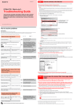
RFM-1000/1100
TECHNICAL MANUAL
SEARCH
STOW
Ver. 1 June 2012
RFM-1000/1100 Technical Manual
WARNING
Make all electrical and coax connections from the controller to the
mount and LNB's BEFORE applying power to, or connecting the
satellite receiver to the controller.
Note: When the controller is turned OFF it will still pass voltage from the receiver to the
LNB if the receiver is plugged in to 110 AC. Shorting of the coax at any time during
installation may cause damage to either the Controller or the DiSEqC Switch. Failure to
follow this procedure can result in voiding of warranty replacement, not to mention time
spent trying to troubleshoot a system that does not perform.
90% of all problems are a result of CONNECTIVITY or CONFIGURATION.
2
RFM-1000/1100 Technical Manual
I
ndex
System Bill of Materials
4
Controller Front View
5
LCD Graphics
6
Controller Rear View
7
Configuration
8
Special Function Dip Switch Settings
9
Manual Movement
10
Wiring Diagrams
11
Operation
13
LCD Displays
14
Service Messages
16
Firmware Upgrade
17
Checking Voltage at the DiSEqC Switch
18
Returning Product to the Factory
18
Product Support
20
3
RFM-1000/1100 Technical Manual
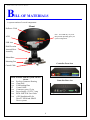
B
ILL OF MATERIALS
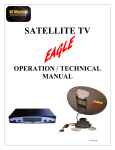
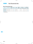
A system consists of several components.
Reflector / Dish
Mount
Note: Your LNB may vary from
that pictured depending upon your
system configuration.
vGPS
LNB Arm
Dish Elevation
Arm and Skew
Assembly
Mount Base
Mounting Feet
Controller Front view
Control Cable
Items included with the system and not
shown.
1 ea Roof top Connector Housing
1 ea Clam Shell
1 ea LNB Landing Plate
15'
Control Cable
1 ea Connector, green, 12 pin
1 ea Power Supply, 12 VDC 7 amp
1 ea RFM-1000/1100 User Guide
1 ea vGPS Installation Kit for
DirecTV SWM and SHAW
Direct systems.
Controller Rear view
4
RFM-1000/1100 Technical Manual
F
ront view
POWER "ON".....
SD Card Slot ...............
LCD Display........................
TO FIND SATELLITES .............
TO STOW THE MOUNT .....................................
Note: Pressing SEARCH / STOW at the same time will turn POWER OFF.
5
RFM-1000/1100 Technical Manual
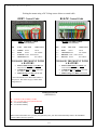
L
CD graphics
AVAILABLE CONFIGURATIONS
TV NetworkS
DirecTV SWM =
Dish Network =
Bell Express =
SHAW Direct =
99, 101, 103 Satellites
110, 119, 129 Satellites
82, 91 Satellites
(For Canadian Use Only)
107.3, 111.1 Satellites (For Canadian Use Only)
CONDITIONS
Stowed
Power shuts down automatically after stowing. If dish is stowed and power is turned
ON, the display will continue to show Stowed for two minutes if no other command is
selected then the power will shut down automatically.
Searching
Will display as the dish is in the searching routine and not peaking.
Peaking
Will display if the dish is peaking a signal.
Locked
Will display when the dish has completed searching and is Locked onto the
correct satellite (s) (TV Services). Two 1/2 minutes after locking onto satellite(s) the power
will shut OFF.
Stowing
Will display when dish STOW command has been selected and the dish is moving to the
Stowed position. When STOWED the Power will shut OFF automatically.
6
RFM-1000/1100 Technical Manual
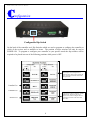
R
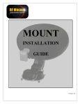
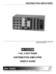
ear view
Model No.
Controller-1
To Satellite Receiver
To Antenna..................
Configuration "Dip" Switches
Factory Maintenance Port .................
Control Cable to Roof Mount Connections...
Ignition STOW option and 12 VDC....................................
Alternate Power IN (12 VDC).......................................................
CONNECTIONS
TO SATELLITE RECEIVER
This is a pass through and a coax connection to your satellite receiver (Satellite IN)
TO ANTENNA:
Coax connection from the Antenna's LNB to the base of the mount (see configuration to
determine which coax at the base of the mount goes to the controller).
CONFIGURATION 6 PIN DIP SWITCH:
Used for programming or configuration of the controller (See Configuration)
FACTORY MAINTENANCE PORT
Used for factory diagnostic purposes
CONTROL CABLE CONNECTION:
Termination of the 12 wires of the control cable to the controller takes place here.
OPTIONAL IGNITION STOW and POWER:
Connection for optional Ignition STOW and Optional 12 VDC power
ALTERNATE POWER:
Input for 12 VDC from a 12VDC 7 amp. power supply.
7
RFM-1000/1100 Technical Manual
C
onfiguration
Configurable Dip Switch
On the back of the controller are 6 Dip Switches which are used to program or configure the controller to
which of the services and or satellites to locate. The position of these switches will only be read at
POWER ON. To program or configure your controller to your specific needs the dip switches will be
required to be placed into one of the following positions while power is OFF.
El 45 degrees up, Skew 45 degrees, return to
Skew 0 degree, AZ 360 degree turn to
clockwise limit, return to stow position and
stow. Continuous movement of the mount
until power OFF.
Canadian Use
Canadian Use
El 45 degrees up, Skew 15 degrees, simulate
satellite peak, clockwise in AZ to 45
degrees, return to Skew 0 degree and stow.
Continuous movement of the mount until
power OFF.
Switch Test
8
RFM-1000/1100 Technical Manual
S
PECIAL FUNCTION Dip Switch Settings
The Dip Switches may be configured to operate the mount in a special way depending upon their
settings. The position of these switches will only be checked at POWER ON. After the settings have been
changed the controller will follow the commands given by the changed settings. The "Special Functions"
will perform the following actions:
To EXIT any of the following functions press SEARCH and STOW at the same time then
release. This will power OFF the controller and allow you to change the dip switch settings.
SHOW Mode
When the switches are in this position and the SEARCH button is pressed, the mount will
Raise in Elevation,
Skew a predetermined amount,
Rotate 45% in Azimuth,
Simulate peaking on a satellite,
Pause and then return to the stowed position and will continuously repeat this procedure until the
dish is stowed. It is designed to show the mount in all its movements for display purposes.
MANUAL Movement AZimuth
When the switch is in this position and the power is turned ON, press the SEARCH button and the
mount will respond by moving clockwise. Press the STOW button and the mount will respond by moving
counterclockwise in azimuth
MANUAL Movement ELevation
When the switch is in this position and the power is turned ON, press the SEARCH button and the
mount will respond by moving UP. Press the STOW button and the mount will respond by moving DOWN
in elevation.
MANUAL Movement SKew
When the switches are in this position and the power is turned ON, press the SEARCH button and
the antenna will respond by rotating clockwise. Press the STOW button and the antenna will respond by
rotating counterclockwise in skew.
Note: It is the responsibility of the person changing the settings to return them to the proper configuration
following any Special Setting change. Only change the dip switch configuration when the power is OFF.
If your system does not seem to operate properly, turn the power off (see procedure above) and check the
position of the Dip Switches.
9
RFM-1000/1100 Technical Manual
M
ANUAL MOVEMENT
The Manual Movement mode will "manually" move the mount when the dip switches are put in a
specific mode and powered ON. It will allow you to move the mount in all directions in Elevation,
Azimuth and Skew.
CAUTION: The mount will move at your command. Know where your dish is before you start to move it.
You do not want it to scrape across your roof. Make sure of your clearances before you move.
SEARCH button - Raises
STOW button - Lowers
SEARCH button - Clockwise
DOWN button - CounterClockwise
SEARCH button - Clockwise
DOWN button - CounterClockwise
Turning Power ON will
start the automatic SHOW
movement
10
RFM-1000/1100 Technical Manual
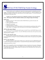
W
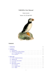
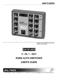
IRING DIAGRAM
To Satellite Receiver
Alternate
12 VDC Input
Control Cable
Connection
To Antenna
Ignition Stow
and
12 VDC Input
Configurable Dip Switches
GREY CONTROL CABLE
(Green Connector)
Pin
Color
How Used
BLACK CONTROL CABLE
(Green Connector)
Where Used
P1 = Violet
Limit Sensor
EL Up
P2 = Dk Blue Limit Sensor
AZ
P3 = Green
Limit Sensor
EL Down
P4 = Gray
Encoder
SK
P5 = Yellow Encoder
AZ
P6 = Brown Encoder
EL
P7 = Black
Ground
GND
P8 = Red
VCC
P9 =
White
Power
AZ-B
P10 = Pink
Power
AZ-A
P11 = Lt Blue/Tan* Power
EL-B
P12 = Orange Power
EL-A
*Tan will substitute for Lt Blue when Lt Blue is
not present. This will be on cables longer than
15'.
Pin
1
2
3
4
5
6
7
8
9
10
11
12
11
Color
=
=
=
=
=
=
=
=
=
=
=
=
How Used
Where Used
Brown Stripe Limit Sensor EL Up
Black Stripe Limit Sensor AZ
White
Limit Sensor
EL Down
Gray
Encoder
SK
Purple Encoder
AZ
Blue
Encoder
EL
Green
Ground
GND
Yellow VCC
RED
Power
AZ-B
ORANGE Power
AZ-A/Skew
BROWN Power
EL-B
BLACK Power
EL-A/Skew
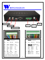
RFM-1000/1100 Technical Manual
Raising the mount using a DC Voltage source direct to control cable
GREY Control Cable
BLACK Control Cable
GREY CONTROL CABLE
(Green Connector)
How Used
BLACK CONTROL CABLE
(Green Connector)
Pin
Color
Where Used
9=
10 =
11 =
12 =
WHITE Power
AZ-B
PINK
Power
AZ-A/Skew
Lt BLUE or Tan* Power EL-B
ORANGE Power
EL-A/Skew
Pin
Color
How Used
Where Used
9=
10 =
11 =
12 =
RED
Power
AZ-B
ORANGE Power
AZ-A/Skew
BROWN or Tan Power EL-B
BLACK Power
EL-A/Skew
TO RAISE THE MOUNT WITH
A BATTERY
TO RAISE THE MOUNT WITH
A BATTERY
ELEVATION Orange and Lt Blue (or
tan) will raise and lower the mount
AZIMUTH Pink and White will rotate
the dish in.
SKEW Orange and Pink will tilt dish.
ELEVATION Brown and Black will
raise and lower the mount
AZIMUTH Red and Orange will rotate
the dish in.
SKEW Orange and Black will tilt dish.
*Tan will substitute for Lt Blue when Lt Blue is
not present. This will be on grey control cables
longer than 15'.
IGNITION STOW
(OPTIONAL)
P1 =
P2 =
P3 =
P4 =
To Positive side of Battery 12VDC
To + 12 VDC side of car ignition when ON
To Ground of Battery
To Ground of Battery
2+ 1+
4- 3When wired in this manner and you turn your ignition key ON, your dish will automatically return to the STOWED
position which is the travel position.
12
RFM-1000/1100 Technical Manual
O
peration
POWER ON
Pressing the POWER ON button will turn ON the power to the controller enabling it
to perform the next function. Wait for this display to appear then select a function.
SEARCH (UP)
Pressing the SEARCH button will instruct the mount to begin its searching routine
and locate the satellites according to the settings of the dip switches.
STOW: (DOWN)
Pressing the STOW button will instruct the mount to return to its stowed or travel
position and turn power OFF automatically. Note: be sure 12 VDC is present.
POWER OFF
Pressing the SEARCH and STOW buttons at the same time will manually turn the
Power OFF.
AFTER LOCKING ONTO THE PROPER SATELLITE: The controller will remain ON for a short
period of time and then automatically turn OFF.
AFTER STOWING: The controller will automatically turn OFF.
13
RFM-1000/1100 Technical Manual
L
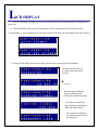
CD DISPLAY
The LCD Display is designed to let you know the status of the mount and what it is doing at any
given time.
When POWER is first turned ON the display will show disposition of the dish on the roof.
("Configuration" is the Programming Service that has been selected by the positioning of the dip switches.)
During the SEARCH process the display will show the various stages of acquisition.
Indicates that the dish is in
its acquisition mode and is
moving.
*
See below
Indicates that the dish has
located a satellite and is
Peaking for optimum strength.
The system is identifying
the satellite by sampling the
DSS and DVB carriers.
The system has identified
the satellite and has locked
the frequency..
14
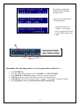
RFM-1000/1100 Technical Manual
The system is scanning the
satellite ID and will display
its identity (xxx).
The system is setting up the
SWM acquisition
Acquisition and lock is
complete. Your satellite
receiver now has full control
over the SWM or other style
LNB's.
*
Skew (degrees)
Elevation (degrees)
Azimuth (degrees)
Remember, the only thing you have to do to operate this system it to.....
1.
2.
3.
4.
5.
6.
Turn POWER ON,
The status of the dish will appear, either "STOWED" or "NOT STOWED".
Press SEARCH or STOW depending on what you want the mount to do.
If STOW is pressed, the dish will return to its travel or stowed position.
If SEARCH is pressed, then wait for "LOCK" to appear. This signifies "locked on satellite".
After acquisition or stow the POWER will turn OFF automatically.
15
RFM-1000/1100 Technical Manual
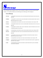
S
ervice messages
Service messages will be displayed on the LCD screen should a condition occur that a person should be
alerted to. If a condition should occur the following Service Messages will be displayed:
Service Message
AZ Count
Is displayed if azimuth motor current can be detected in both directions but no counts are
detected.
AZ Motor
Is displayed if no azimuth motor current is detected or maximum azimuth motor current is
detected and there are no counts.
AZ Limit
Is displayed when total azimuth motor counts exceed maximum count value plus 20%.
EL Count
Is displayed if elevation motor current can be detected in both directions but no counts are
detected.
EL Motor
Is displayed if no elevation motor current is detected or maximum elevation motor current
is detected and there are no counts.
EL Limit
Is displayed when total elevation motor counts exceed maximum count value plus 20%.
SK Count
Is displayed if skew motor current can be detected in both directions but no counts are
detected.
SK Motor
Is displayed if no skew motor current is detected or maximum skew motor current is
detected and there are no counts.
SK Limit
Is displayed when total skew motor counts exceed maximum count value plus 10%.
No Signal
Is displayed when the Antenna Controller has searched the entire sky but no signals were
detected to stop and peak.
No Sat
Is displayed when the Antenna Controller has searched the entire sky but no Satellites
were found or identified.
16
RFM-1000/1100 Technical Manual
F
irmware upgrade
Should any firmware upgrades become available you may obtain them from your installing dealer
or by contacting RF Mogul direct. To load software place the file on your Desktop and transfer the file to
your SD Card and into the "root directory. Insert your SD Card into the controller and turn power ON.
The software will automatically download to your controller. Remove the SD Card once the load function
is complete.
When should you think about downloading new software?
1. To take advantage of new innovative features offered by the latest revision of software.
2. If you have called your installer and he recommends it.
3. If you read the History of the new software and you determine that you could benefit from its
features.
What style of SD Card do I need to use?
You may use any size of SD Card and in any format. It is not restrictive.
MAC or PC?
The software load will take either style of computer.
How to I tell that my software is loading?
The LCD display will display
SD CARD DETECTED
LOADING SOFTWARE
When finished it will display
LOAD COMPLETE
17
RFM-1000/1100 Technical Manual
C
hecking Voltage at DiSEqC Switch
If you are asked to check voltage at the DiSEqC Switch, this is the procedure to accomplish the task.
1.
2.
3.
4.
Turn the power to your controller OFF.
Disconnect the coax going to the receiver.
Place all dip switches on the back of your controller to the "DOWN" position.
From the back of the controller marked "Antenna" connect a coax to the base of the mount to the
small coax that is "unmarked, black or white"
5. Disconnect the Yellow and Red coaxes from the LNB's. Note: these two (2) coaxes come directly
from the DiSEqC switch.
6. Place your Multi-Meter on 20 Volts DC.
7. Turn ON the power to your controller.
8. Press SEARCH to start the switch check, wait approx 10 seconds before continuing.
9. The LED display will display "Testing SW1 or SW2" (SW1 is the LNB, SW2 is the vGPS) and will
begin to alternately supplying and switching 13/18 DC Volts to one coax and then do the same on
the other. Voltage will read around 12+ or 17+ volts.
10. Carefully check the voltage switching by placing one of your probes on the center conductor and
the other on the outside of the connector on one coax and then check the other in the same manner.
Care should be taken to not create a short during this process. Creating a short will give you a false
reading and will cause you to think you have a DiSEqC switch problem.
11. If you should accidentally short the cable during this procedure you will need to restart your
controller and do it again. It will not harm the controller or the switch, but be careful.
12. If you do not have voltage present on both the LNB and vGPS during this test then YOU HAVE A
BAD DiSEqC SWITCH and it will need to be replace.
What can cause a DiSEqC failure?
1. A shorted cable going from the switch to the LNB or vGPS.
2. Input voltage greater than 21 Volts DC so do not use a 29 Volt Power Inserter from DirecTV. If
you have a RFM-4100 SWM system a 21 Volt Power Inserter is required.
3. An open cable from the switch to the controller will not allow the switch to work properly.
4. Connecting coax while receiver is sending voltage to the LNB and causing a short.
18
RFM-1000/1100 Technical Manual
RETURNING PARTS TO THE FACTORY
Parts returned to the factory must contain a Return Material Authorization (RMA) which will be provided
by the RF Mogul Technical Support Department at the time of troubleshooting. This will ensure proper
accountability of returned equipment or parts. Make sure that the following information is contained on
your shipment.
RF Mogul
Attn: Product Evaluation Department
RMA # _______________
3604 South Via Terra
South Salt Lake City, UT 84115
You must include your Return Address and Telephone Number failure to do so may result in you being
billed for a non-returned part.
We appreciate your business. If you need to contact us please see
the information below.
RF Mogul
3604 Via Terra
South Salt Lake City, UT 84115
Tele 801-895-3308
Fax 801-478-5850
www.rfmogul.com
[email protected]
[email protected]
Thank you for purchasing a RF Mogul System.
19
RFM-1000/1100 Technical Manual
P
RODUCT SUPPORT
For product support please contact the following
UNITED STATES
Your Installing Dealer is your first line of defense. If resolution cannot be made it may be passed
onto the manufacture.
CANADA
Your installing Dealer or Distributor
Your issue may be passed onto the manufacture for assistance.
MEXICO
Your installing Dealer or Distributor
Your issue may be passed onto the manufacture for assistance.
THE MANUFACTURE
RF Mogul
3604 South Via Terra
South Salt Lake City, UT 84115
Tel - 801-895-3392
www.rfmogul.com
[email protected]
[email protected]
[email protected]
20