1
Model 2245
Stereoohonic
Becdiver
Model 2245
rrrä-roArnt-"
Stereoohonic
Recriiver
MARANTZ CO,, INC..P.O. BOX 99.SUN VALLEY CALIFORN IA.91352
A WHOLLY-OWNED SUBSIDIARY OF SUPERSCOPE INC., SUN VALLEY CALIFORNIA 91352
Elt,seE.üaürgüEr
We sound betler.
WARRANTY
Maranrz Company, lnc-, prosdly warrants your Maränlz prodüct
in material and workmanship as lollows:
io
be free o{ manulacturins defects
From date oI Purchase
Erectroniccomponenrsa'dReceive's
iääH: :I:i:
.
PARTS '
LABOR PARTS LABOR PARTS LABOB PARTS
LABOR
+Channd Remote Control
Pluq-in Matrix Decodeß
Speakeß and Cabinets
3
3
3
3
3
3
veaß
years
years
years
yeals
yeaß
5 years
5 y€aß
TO VALIDATE YOUB WARRANTY, YOU MUST FILL OUT AND IVIAIL THE WABRANTY BEG'
ISTRATION CARD TO MAFANTZ COMPANY, INC., P. O. BOX 99. SUN VALLEY, CALIFORNIA
91352. WITHIN TEN DAYS FOLLOWING THE DATE OF PURCHASE.
For Wanänty repair, send this Ploduct to Maran? Companv, lnc., 8'150 Vineland Avenue, Sun Vallev,
California 91?52, or to an AUTHORIZED Mamnlz Service Station. All shippinq charges must be prepaid,
lvläEntz will pay return shipping charges ro anv d6iqnated Point within the United States.
This Wärranty is void if the terial nümber has been altered or removed; if the Product is mddilied or
repair€d in any manner which Marantz believes mav aff€ci the reliabilitv of the product; iI the product
k not op€räted in aeoldance with the insttuction manual.
l/brantz shall have no liability whätsoever lor consequentiäl damages. The sole resPonsibilitv o{ Marantz
Comp.ny, Inc,, under this Wairanty shall be limited to the tePair oI the product, or teplacement thereoi
in rhe sole diicrerion ot [4arantz company, lnc.
EXCEPT TO THE EXTENT THAT APPLICABLE LAW PBECLUDES A DISCLAIMER OF WARRANTY,
THERE IS NO III/IPLIED WARRANTY OF IIIERCHANTABILITY OR FITNESS WITH RESPECT TO
THIS PRODUCT, NOR ARE THEBE ANY OTHEB WARBANTIES WHICH EXTENT BEYOND
THE PROVISIONS OF THIS WABRANTY.
81
50
Vineland. ,$tetue. Sun Valle./,
Califltnio 91352
REGISTRATION FOR MARANTZ 3.YEAR GOLDEN
WABRANTY
lvlodel: Marantz IVlodel 2245
Serlal No-
,nitffi piiE#\$fl fd'$i $ifi fi$iFiII
Purchased From {Name)
>
Date Wardnty Replv Cdrd l,4ailed
The above information becomes yo!r permanent re.ord ol
a valuable purchase. lt shouLd be promptly filied in at the
same time that vou fill ln and mai th€ waiianty reg stratlon
reply cärd to t\,4arantz. Thls information provides a !alüabie
lnsuränce record and must also be referred 1o should Vou
häve any correspondence wirh Maranlz.
l\,4uting
TABLE OF CONTENTS
Circuit
12
Selector Switch
Preparation for Use
Rear Panel Connections
Phono
Tape ln
Tape Out
Auxiliary
Ouadradial
l\4ain ln and Pre Out
Loundspeaker Systems
2
2
2
2
2
3
3
3
3
4
Anlenna Attenuator
5
Power Connections
Connection to AC Outlet
Convenience Outlet
Simplif ied Operating Procedure
Tuning lvleters
Tuning
l\4ono Switch
Tape lMonitor Switch
Loudness Switch
Low Filter Switch
Hi Filter Switch
l\4uting Switch and Level Control
lVIain Controls and Switches
Selector Switch
Balance Control
Volume Control
Bass l\4id and Treble Controls
lVIain-Spkr Remote Switch
Front PanelJacks
Dubbing Out
Dubbing ln
Stereophones
Some Suggestion on Using Tape Recorders
with Your Model 2245
Recording and Playback
Becording
Playback
lMaa<ing
Two Recordings Sirnultaneously
Becording a Long'Duration Program
Copying and Editing
Convertinq Your Stereo System to
4 channel
Technical Description
General
Functional Description
Front End
lF Stages
Lim iter
FM Stereo Demoduläror
12
5
5
5
6
6
12
Tape Signals
Tape l\4onitor Switch
Phqno Signals
I\4ono Functions
Control Circuits
Balance Control
Volume Control
Tone Ampli{ier
Hi-Lirw Filter
Output Stage and Protective Circuits
13
13
13
14
14
15
15
15
Technical Specificataons
16
Typical Per{ormance Curve
17
Service Note
19
6
6
6
6
6
6
1
7
7
7
7
7
8
8
8
8
I
8
8
I
I
11
11
11
11
12
12
12
LIST OF ILTUSTRATIONS
1.
Rear Panel Connection Facilities and
Adiustments
2
Connectlons 3
Conneclion
4
4. AIVI Ferrite-rod Antenna
5
5. Front Panel Controls and Jacks
1
6. Stereophone Plug
I
7. Arrangement oJ Two Tape Becorder I
8. Connection Diagram
10
Functional Block Diagram
1'l
10. PhonoEqualizationCharacteristics 13
11. Tone Control Characteristics
14
12. Low and High Filter Characteristics 14
13. FlVi Characteristics
17
14. Stereo Separation
17
15. Harmonic Di$ortion
18
'18
16. Frequency Response
17. Päckinq lnstructions
1S
2. Loudspeaker System
3. Fl\4/A[\4 Antenna
A{-
mffi
s#ft
rT'!f-}p$
F{3HüWffiMM
ffi ffi ru ffi ffi
For optimum performance and enjoyment from
Vour l\,4odel 2245 Sleteo Receiver, please srudy
Your lMarantz Model 2245 all solid state recelver
incorporates the advanced circuitry for which
l\4arantz is famous in the audio component
lion are not complicated, but its flexibility
ind!rstry.
Unparalleled technology and innovation made possi
ble this combination of three superb component
sections on a single chassis: Tuner, Preamplifier,
and Power Amplifier. lnternal connections between these cornponent sections ensure optirnum
per{orrnance from each section, and retain the full
flexibility o{ separate components- The extraordinary flexibility o{ your l\,4odel 2245 permits
the connection of: two srereo pairs of loudspeak'
ers; headphones; a lurntab e or record changer; an
additional luner (such as SW or LW) and ä TV
solrnd source. Record, pLayback, and copying
capabilities are included {or a lape playback deck
or two recorders.
these instructions carefLllly. lnstallation and opera
and
fpatu'es deserve yoL/ beLomlrg ldnrllal wlth ils
controls and connections.
This manual is divided into two parts The first
in simple,
non-technical lanqllage. The second describes the
2245 in mote detail with technical specifications,
Junctional explanations, and special application
covers installation and operation
discl]ssions.
For quick identification of the controls
and
connections, references to them are printed in
boldface type, exacrly as thev appear on the fronl
and rear panels o{ Your Receiver-
I
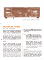
AFTER UNPACKING
It
is advisäble to save all original packing material
to prevent damage should you wish to transport or
ship the Receiver (refer to Figure lT for packing
instructionsl.
Please inspect your l\,4odel 2245 catelully Io( aoY
signs of darnage in transit. lt has undergone
stringenl quäliry conTrol inspection dnd rests ptiot
to packing, and left the {actory in perfect
operating condition.
lf the unit is damaged, notify the carrier without
delay.
Onlv the consignee may institute a claim with the
carrier for damage during shipment. However, the
l\4arantz Company will cooperate {ully in such an
Save the damdged carlon as evidence
by the carrier.
jor inspeclion
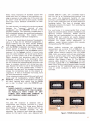
Figure
l.
ßear Panel C0nnectiofl FacililiesEnd Ad,ustmeds
C
PREPARATION FOR USE
REAR PANEL CONN ECTIONS
All
signal connections to the l\4odel 2245, wilh the
c
of the
Fl\4 antenna and loudspeakers,
$ould be made with shielded audio cables. Figure
1 shows the location of input and output jacks on
the rear panel. These jacks are for "permanent"
connections. Front panel jacks and their use will be
discussed ldtpr. The rear panel siqndl connections
are arranged in slereo pairs. To avoid confusion,
connect one cable at a time between the 2245 and
the other components of your system. ln this way,
you wili avoid cros+connecting channels or con
fusinq siqnal sources with destinations.
exception
PHONO
I
he phono jdcks are intended lor use with
itself. Keep the two PHONO connecting cables and
the grounding wires close togelher to minimire
"ground loops."
TAPE IN
The pair o{ TAPE lN jacks serve two purposes:
1. Wilh the selector slvitch irJ'TAPE'bosition,
signals can be played from a tape recorder
set for playback mode of operation. This
permits playinq the tape sou rce stere
ophonically or monophonically as indicated by position of MONO pushswitch.
switch in any other
position, and while your tape recorder is
recording, you can monitor the resulting
2. With the selector
tape quality bv depressing the
TAPE
magnetrc phono cartridges requiring a standard
47,000-ohm resistive load. lf hum is heard when
playing records, it is usually evidence ol improper
grounding or shrelding ot the record prayer or its
connections. Try reversing the polarity oJ the
turntable's power plug. lf this is ineffective,
connect a separate ground wire from the tLrrntable
TAPE OUT
tone arm is mounted on a wood panel or is
otherwise insulated from the turntable frame,
connect the lone arm mounting base to the
grounding wire with d short wrrp. ll thc t!1,o pars
o{ signal wires in the arm have a single overall
shield, trv grounding lhe shield instedd ol the drrr
Connectinq these iacks to the line or "tadio"
inputs of a tape recorder permits recording from
the program source indicated by the selector
switch. The signals available at this pair of jacks are
not affected by the balance. volume, treble, mid,
bass, LOW FILTER, Hi FILTER. or LOUDNESS
and lvlONO pushswitches on the front panel.
or record
changer frame to the CHASSIS
GROUND binding posts of the lModet 2245. tf the
MONITOB pushswitch. This presumes that
your recorder is equipped with separate
record and playback heads and separate
record and playback electronics.
Figure
2.
Loudsteaker System Connections
AUXILIARY
LOUDSPEAKEB SYSTEMS
High level AUX input iacks are for miscellaneous
sources such as extra tape players with self
contained playback preampl if iers, phono cartridges
wilh RIAA equalized high-level output, additional
t!ners and/or receivers, TV sound outputs, and
other external components.
The SPEAKEB SYSTEIMS terminals on the rear
panel will accommodate Iwo stereo paars of
loudspeaker systems of rated impedance between 4
ohms and 16 ohms. When using only one stereo
pair o{ loudspeakers, connect them to the MAIN
terminals. The REII4OTE {erminals are for a second
stereo pair of loudspeakers.
OUADBADIAL
ln anticipation of rhe coming o{ 4 channel stereo
Selection of loudspeaker systems is made wilh the
lvlAlN-SPKR-REMOTE pushswitches on lhe front
broadcastinq, your l\lodel 2245 is equipped with an
ourpur OUADRADIAL jack. The signal available at
this jack is the unequalized, buffered output of the
Fl\,4 discriminator. lts level, frequency response
characteristic and output impedance are ideal to
drive anv 4 channel adaptor. This jack can also be
used as a simple white noise generator for {re
quency response check of loudspeakers or ampli
fiers, with the lvlodel 2245 in FI\4 mode and tuned
off from any FM signal.
panel.
MAIN lN and PRE OUT
Ordinarv #18 qauge, 2 conduclor lamp cord
("zipcord"i may be used for normal distances (to
about 25 Jeet) belween your 2245 Receiver and
the l!4odel 2245 preamplifier
power amplifier inputs are per
+ormed externally. Special jumper plugs normally
interconnect these lvlAlN lN and PRE OUT iacks
Removing these two special jumper plugs allows
you 10 use vour 2245 as an independent basic
stereo amplifier and/or an independent stereo
control center, Be sure to replace the iumper plugs
between the MAIN lN and PRE OUT jacks for
Connections Jrom
outputs
to the
normal operalion.
3
your lvlodel 2245 to
power
supply such as
a loudspeaker with bualt in
"common"
Tl,e
an electro-static loudspeaker,
may be
speaker
conneclion terminal of such a
qrounded
power
supply.
its
through
capacitivelv
the
Model
terminals
of
Vlake sure the GROUND
"common"
of
terminals
2245 are connected to the
Use caution when connecting
such loudspeaker system.
your loudspeakers. For longer lengths, +16 gauge,
or heavier wire should be used to ensure optimum
speaker performance.
When connecting a slereo pair of loudspeakers,
to
it
is
ensure correct relative phasinq
important
(polarity). When usinq identical loudspeakers,
simply code one wire of each pair at both ends
with a knot, tape. etc.
J
(Note: Close inspection of ständard zipcord will
'pvaal \orp lorr o'codinq o'1 lhp r1'ulatron,4,q,,
rioqF o' g'oovp on ono pouo. onp o ll'F wrrp" näy
be "silver" while the other is bare copper.) Coded
wires help insure identical connections for each
channel,
For each channe. the coded wire can be connecred
between the "commoi" termjnal of your
loudspeaker and the GROUND terminal of the
amplifier channel. The remaining uncoded wire is
then connected between the remaininq Loudspeaker
and amplifier lerminals. This insures correct
polarity or phasing o{ identical loudspeakers.
C
l{ there is any doubt about phasing o{ loudspeaker
pairs, or if they are not identical loudspeakers, a
simple listeninq test can verify correct phasing.
With program signals fed to both channels, and
with the MONO pushswitch depressed, the sound
should appear to originale at a point midway
between the loudspeakers, with the balance control
centered. As the balance contro is turned away
from the center position, the sound source shou d
appear to move toward one of the Loudspeakers.
Room acoustics can somelimes make this test
ambiquous or confusing. lf so, lemporari y rnove
the loudspeakers as c ose toqether as possible. Then
set the controls for balanced IMONO operätion and
listen to program material with strong bass pass
ages. Reverse the wires to one of the loudspeakers
and listen to the same passage again- lf there is
.ofic"obly less b"\s w l I' c 'Fvp 'ad , orn"cr:on.
change the connections back to the original ar
ranqement. lf there is noticeably more bass, leave
the wires connected in reverse,
These phasinq procedures should be used with each
stereo pair of Loudspeakers, whether IMAIN or
REMOTE. lf both pairs of loudspeakers are used in
the sanre listening area, ensLrre that the [4AlN
peir is also "in phase" with the REMOTE pair.
CAUTION:
NEVER DIRECTLY CONNECT THE LOUD
SPEAKER TERIV]INALS OF ONE CHANNEL
IN PARALLEL WITH THOSE OF ANY
OTHER. ANY RESULTING DAMAGE IS
NOT COVER ED UNDE R WARRANTY.
shielded 300ohm cable. (An unshielded lead-in
wire can act as än omnidirectional antenna, and
can cancel the directional benefits of your
ä1'pr1a.) Lolv los.300.ol_Tl \' eld"d cdb'p ' or\,sls
of two inner conductors plus an ouler shield and
insulating jacket. This type of shielded cabe
effectively prevents the lead-in from contributifg
multipath distortion.
For rural areas, it is recommended that a
loca
dealer be consulted about antenna installation and
lightning arrestor protection- I\,4aster antenna
system are not recommefded {or use with your
Model 2245; such systems are usually designed
expressly {or television reception and frectuently
suppress FM siqnals before distribution. ln
addition, rnaster antenna systems often severely
limit good qLrality FIVI reception.
Where ouldoor antennas are prohibited or
inconvenient, use a simple form of 300-ohm, TV
"rabbit ear" antenna or the simple ribbon type
{olded dipole anterrna supplied with the lvlodel
2245. Aarh are practical änd will qive satisfactory
results in primarv siqnal areas. Your [,4odel 2245
Receiver will accept either a 75 ohm or 300 ohm
antenna. (See diagram Figure 3.) The 300ohm
inrenna cable should be connecled to the two
terminals marked FIM on the ANTENNA terminal.
When using 75 ohm coaxial antenna cable, connect
its sh;eld to the "G" (GROUND) terminal, and its
inner or center conductor to either of the FM
üü
FM ANTENNA
The best F [/] reception is obtained with
a
type antenna, moLnted on a qood
quality rolor system. For fringe areäs, I\4arantz
recommends a Log Periodic antenna with six or
Log-Periodic
more elements designed expresslV Jor
FM
reception. For minimum local noise and multipath
picl<Lrp by the lead in wires, Lrse a balanced änd
Fiqure
3.
Fl',4/A[4 Antenna Connection
POWER CONN ECTIONS
The i!4odel 2245 is equipped with a
universal
power lransformer to permit operation at any
standard AC line voltage and at frequencies oJ 50
Hz to 60 Hz. For operation at line voltaqes other
than indacaled on the rear panel nameplate, ha/e a
qualified technician perJorm the simpie wiring
changes necessarY.
CONNECTION TO AC OUTLET
With the front panel power pushswitch "oot," plug
the line cord into an electrical outlet supplyinq the
proper voltaqe. CAUTION: DO NOT PLUG YOUR
MODEL 2245 INTO A DC OUTLET. SINCE
SEBIOUS DAIVIAGE WILL OCCUR.
CONVENIENCE OUTLET
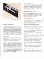
Figure
4. AM Ferrite-rod Antenna
J
One UNSWITCHED and one SWITCHED AC
oUTLET are provided on the rear panel for
powering associated components of your system
(tape recorder, record player, etc.),
ANTENNA ATTENUATOR
SIMPLIFIED OPERATING PROCEDURE
The ANTENNA ATTENUATOR can be switched
into or out of the anlenna circuit. Use the
ANTENNA ATTENUATOR switch in the "lN"
position only when overloading is apparent from
reception of one station at several points of the
dial and is affecting reception of a desired station.
Overloading may also cause severe distortion which
will not disappear with proper antenna orientation.
(NOIE: With thE ANTENNA ATTENUATOR
switch "1N", the FI\4 sensitivity and the number of
stations that can be received are greatly reduced.)
When operating the fi,4odel 2245 Stereo Receiver
for the first time. follow these sirnple directionsLater, full advantage can be laken of its versatility
with the remaining cgntrols and pushswitches.
AM ANTENNA
Your Receiver is equipped with an Al\4 {errit+rod
antenna,
BEFORE USING THE I\4ODEL 2245, PULL THE
ANTENNA OUT AS SHOWN IN F IGU RE 4,
The {erriterod antenna will give you satistactory
results Io primary signal areas. However, an
outdoor dntennd \rvill piovide better receptiol.
Two single wires are required to make an AlVl
outdoor antenna, First, connect one end of a single
wire to the AlVl antenna terminal on the rear panel,
and the other end at a very high posilion oLltdoors
(the higher the better), or swing it from the
window of your room. Next, connecr the other
single wire between the "G" (GROUND) terminal
of your Model 2245 and an authenticäted earth
ground (such as a metal waterpipe).
5
L
Connecr r1p F l\,4 dltenrd
ate terminals on the rear Panel.
Slep
lo rhe dpproori
Step 2. Connect the speakers to the MAIN speaker
terminals.
Step 3. Check that all pushswitches are in the
"out" position. Pushswitches in lhe "in" position
should be depressed for releasing to the "out"
position.
4. Turn the volume control all the way to the
le{t (counter clockwisei and set the balance control
in mid posirion (poinler to dot ät 12 o'clocki
Step
5. Rotate treble. mid, and bass controls to
i2 o'clock posilion {each pair of pointers to
Step
the
dot).
Step 6. Set N4AIN Speäker pushswitch "in," and
REMOTE "o!t" (assuminq your loudspeakers are
connected to the NIAIN amplifier terminals)
Step 7. Turn on system power by depressing the
power switch.
Step 8. Select the desired program source by
serting the selector switch to the appropriate
)
position. lJ Flvl or A[4 is selected, rotale the
Gvro-Touch TUNING knob until the desired
station is tuned. Adjust the volume control for
comJortable I istening volume.
The tuner section of the l\4odel 2245 is ectuipped
wilh electronically triqqered circuits which automaticallv mute interstation noise and automatical
ly swilch to lhe proper mode of operation for
stereo and monophonic FI\4 broadcasts. ln addition, the STEREO indicator liqht äutomatica'ly
indicates a stereo broadtast.
TUNING
The l\4odel 2245 is equipped with two meters, a
SIcNAL STRENGTH meter and a TUN ING meter,
'1. The SIGNAL STRENGTH
2.
the selector switch. With the TAPE I4ONITOR
pushswitch "in," the amplifier input connections
are switched to the output of the tape recorder
without affecting the signal presented to the tape
recorder's input, thus allowing you to listen to the
signal being recorded beJore and after recording.
This switch is also known as the TAPE-SOURCE
switch.
LOUDNESS SWITCH
For more pleasing tonal balance at low
IV]ETERS
signal strength o{ any Al\,4
recorded and heard is determined by the setting of
l\4eter indicates the
or F lvl broadcast.
The TUNING meter operates on Fl\4 only and
indicates correct station tuning.
LOW FILTER SWITCH
The low frequency filter can be used to redLlce
turntable rumble and low frequency noise. lt will
also. however, slightly atlenuate proqram material,
and should therefore be used judaciously. The
"out" position switches the {ilter out of the
TUNING
circuits.
AM: For opt;mum Al\l reception, tune to the
selected station. Then rotate the tuning knob
HI FILTER
slightly back and forth until the maximum reading
is obtained on the SIGNAL STRENGTH Meter'
The TUNING N4eter is not used for AIVI.
FM: Switch the selector to'ili'anO tune to the
desired station. Then slowly rotate the tuning knob
sliqhtlv back and forth until nraximum reading is
obtained on the STCNAL STRENGTH lvleter, and
the TUNING Meter points to the center scale
position. Your Receiver is now properly tuned.
SWITCH
to a high
pitched interference "whistle" frorn a nearby
adjacent Al\l channel. The high freqLrency {ilter
will suppress this interference, the "scratchy" noise
trom phonograph records, and tape "hiss." The
filter will also, however, slightly attenuate high
frequency progräm malerial, The "out" position
switches the filter out of the circuits.
Al\4 radio reception is sometimes subject
IVIUTING SWITCH AND LEVEL CONTROL
When tuning 10 F[\4 broadcasts with the MUTING
IMONO SWITCH
Depressinq the MONO pushswitch will convert all
input siqnals to the monophonic mode excluding
signals at the RECOBDING OUTPUT and TAPE
dubbing jacks.
ile playinq a sinqle channel source such as TV or
Al\4, depress the I,4ONO pushswitch to feed the
signal through both channels of the 2245.
Wh
When playing a monophonic phonograph record,
use this pushswitch to suppress rumble, common
mode noise and pincheffect distortion.
TAPE MONITOR SWITCH
When this pushswitch is
level
listening, the bass and treble should be boosted.
With the LOUDNESS switch depressed, the bass
and treble are automalically boosted at low level
listening and this tonal balance maintained.
"out," the proqram
being
switch in its "in" position, the mutinq circuil will
eliminare interstalion noise. The muting threshold
can be varied by rotation the lvlUTlNG LEVEL
control on the rear panel, To prevent muting very
weak srations along with the noise, the muting
function may be turned off by releasing the
MUTING pushswitch to "out" position, and thus
switching all muting out of the F IVI circuits.
Figure
MAgru fflruTR$t$
SELECTOB SWITCH
The selector switch selects the program source for
listening or recording. lf a tape recorder's playback
output has been connected to the TAPE lN iacks
on the rear panel, you can select tape listeninq by
selector switch to the "TAPE"
position {with rhe TAPE l\4oNlToB pushswitch ;n
the
C0ntrolsand Jacks
unbalanced room acor-lstics or for any other tonal
imbalance in proqram material. The Jriction_coupl_
ed feature convenientlv allows simulraneous adjust'
menl of bolh channels. The smaller knob adjusts
the response of the left audio channel, while the
larqer knobs adiusts the riqht audio channel
ANI} SWITCHES
rotating
5. Front Panel
the
"out" position).
BALANCE CONTROL
This control alters simultaneously the output level
o{ both channels. As the knob is turned away from
the normal 12 o'clock position, it decreases the
level in one channel, while it increases the level in
the other channel. (Because the balänce control
knob has been set for precise electrical balance
when the pointer is at the indicator dot at the 12
o'clock position, there may be slightly greater
mechanical rotation oJf center in one direction
than in the other.)
MAIN,SPKR,BEN]OTE SWITCH
the loudspeaker terminals to
power
is
{ed. Either the l\4AlN or the
audio
which
pair
o{ loudspeakers may be
stereo
REMOTE
ooerated indüiduallv, or simultdneouslv if both
s*itches ar" depressed. When the two MAIN_
SPKR-REIVIOTE switches are in the normal"out"
posirion, all loudspeaker terminals a'e inlernally
disconnected from the power amplilier section.
aflecled
The sional at the headphones jacl is nor
-The "out"
bv thivlAlN.sPKR-REMOTE swilches
These switches select
päsition allows "private lislening" when
stereo
headphones are used.
)
FBIINT PANET JACKS
VOLUME CONTROL
This is a dual control which maintains
stereo
balance at all normal settings lt controls the level
oJ both output channels simultaneously and has no
effecl on the recording outputs.
BASS, MID AND TREBLE CONTROLS
These controls are used to adiust the tonal balance
program malerial to suit your individual
listening preference. Each control is of the duäl
concentric frictioncoupled type. This permits
separate control of each channel to compensate for
of
7
J
DUBBING OUT
This output is internally connected in parallel with
the TAPE OIJT jacks on the rear panel. Thus, any
signals available
at the rear
panel jacks
are
simultaneously available at the front panel. You
can connect the recording inputs of an externäl
recorder to this jack, using a standard 3'conduclor
plug. Plugs of this type have an insulaled tip, an
insulated ring, and a sleeve for common return or
qround. The tip of the plug receives the lefl
channel of a program, and the ring receives the
right channel (see Figure 6).
equally simple arrangement using the front panel
facililies involves connecting the line inputs to the
dubbing OUT jack and the playback outputs to the
dubbing lN jack.
RECORDING
COMMON
RIGHT CHANNEL
Fiqur€
6. Stereophone nug
DUBBING IN
This jack has a built in switch which automatically
disconnects the rear panel TAPE lN jacks when
you insert a standard 3 conductor phone plug. lt is
intended to receive the playback outputs of an
external tape recorder.
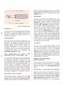
STER EOPHON ES
This iack accepts the standard 3-conductor phone
plug used on standard stereo headphones (see
Figure 6). ll is internally connected to the power
amplifier section throuqh isolation resistors to
provide adequate sound level with popular low
impedance headphones as well as with high
impedance ones, Two or more sets of headphones
mav be used with the aid of "Y" connectors. The
headphone jack outpur is not af{ected by the
MAI N-SPKR-R EIMOTE switches.
SOME SUGGESTIONS ON USING
c
TAPE
RECORDEBS WITH YOUB MODEL 2245
There are several wavs lo connect and operate tape
recorders with your receiver, To avoid confusiön in
the following discussion, reference to "lape
monitoring" assumes that the recorder is equipped
with separate record and playback heads and
separate record and playback preampli{iers. To
further simplify this discussion, a tape recorder
normally connected to the rear panel facilities will
be referred to as the "main" recorder, A separate
recorder normally connecled to the front panel
jacks will be referred to as the "external" recorder.
This general arrangement is illustrated in Figure 7.
RECORDING AND PLAYBACK
The simplest system involves only one
tape
recorder, whose inpurs are connected to the TAPE
OUT jacks (on the rear panel) and whose playback
outputs are connected to the TAPE lN jacks. An
To make a recording. set the selector switch to the
desired proqram source and put the recorder into
the "record" mode of operation. With the TAPE
MONITOR pushswitch in the "out" position, the
original program source will be heard. By depressing rhe TAPE MONITOR push$/vitch (monilor),
rl'e "rpsulls" ol tl^e re(ordi49 while ,l is in
progress, will be heard. A word of caution: With
the tape recorder in the record mode, be careful
no1 to place the selector switch in the "TAPE"
position when the TAPE MONITOR pushswitch is
"out." Doing this feeds the recorder's output
signals bäck to its ;nput terminals, eslablishing a
revertrerating loop. l{ the recorder's playback level
happens to be set higher than its record level, the
resulting echo or "howl" will rapidlV incredse in
volume level. No harm wiil be done to the recorder
or the rece;ver, but the audible effect from the
loudspeakers can be annoying.
PLAYBACK
To listen to a tape already
recorded, put the
recorder in the playback mode of operation and
turn the selector switch to "TAPE". When playing
tape on än external recorder, the recorder's
playback outputs should be connected to the
dubbing lN jack on the fron{ panel. When playing a
tape on the main recorder, make sure nothing is
plügged into the dubbing lN jack, otherwise the
main recorder's playback outputs will be inlernally
disconnected in the receiver,
IVIAKING TWO R ECORDINGS
SIMULTANEOUSLY
This can be done by conn€lcting two tape recorders
to rhe recpiver, as 5hown in figurp /. lo 'nonitol
lhe main recorder, pull the plug out of the dubbing
lN jack and depress the TAPE IVIONITOR push
switch.
RECORDING
A
LONG.DURATION PROGRAM
With two tape recorders connected to the l\4odel
2245 as shown ;n Figore 7, a continuous recording
can be made withoul losing parts of the program
durinq reel chanqes. For example, with the selector
switch set to the desired program source, and the
TAPE MONITOR pushswitch in the "out" po
sition, start the recording on the main recorder,
then prepare the external recorder to beqin record
ing before the main recorder is about 10 run out of
tape. As soon as the external recorder is started,
arnple time will be available to reload the mäin
recorder in preparation for further recording. This
process can be repeated indefinitely with both
machines. At anv time during the recording ses
sion, the recording can be monilored by depressing
the TAPE I!4ONITOR pushswirch.
To Copy from the external recorder to the main
REN4E[.4BER: Disconnecr the plug from the
dubbing lN jack to monitor the n1äin recorder.
lnsert the pluq to monitor the external recorder,
To edit, delete, or leave out program material you
do not wish to include in the copy, simply stop the
machine that is in the record mode, while the
unwanted program mäterial is playing. Some
machines are equipped with a convenienl "pause"
control for this PurPose.
COPYING AND EDITING
Usang
the input/output and control faciliries of the
l\ilodel 2245, and two lape recorders, you can copy
and edit tapes from one machine to the other. The
general arrangemenl of equipment for copyinq and
editing is illustrated in Fiqure 7.
To copy {rom the main recorder to the external
recorder:
Step
1.
Step
2.
Step
3. Put the main
Disconnect the plug from the dubbing
ln jack.
Set the selector switch to "TAPE"
and TAPE IVIONITOR pushswitch to
"out" position.
into the
playback mode and the external
recorder
recorder into the record mode,
recorder:
Step 1.
Step
2.
Step
3.
lnsert the plug into the dubbing
lN jäck.
Set the selector switch to "TAPE"
and TAPE lvloNlTOR Push switch
to "out" position
Put the externäl recorder into the
Playback mode and the main
recorder into the record mode.
CONVERTING YOUR STEREO SYSTEIV] TO
4.CHANNEL
ln the future, it is conceivable that you maV decide
stereo system into a {our channel
to expand your
\ound sycran_. lvls'dnt/ sinolif'e\ trls co'1vprsion
bv of{erinq the lvlodel 2440 Adaptor Amplifier,
which has been speci{icaliy desiqned and engineered
ädd the dimension of fourchannel sound to
your stereo receiver. lt contains a 40 watt con
tinuous (RtMS) Stereo amplifier and incorporates
all the technology, required 10 converl your
to
present [Marantz stereo receiver into a four channel
sound system.
Features of the [Vlarantz l,4odel 2440 Ouadradial
4 Adaptor Amplifier inclLrdel
r
r
r
r
.
.
.
r
.
a\
Ready to accept an exlernal CD4 disc demodulator.
SO pocket for pluqqing in l\,4arantz'SOA-1 änd
SOA-2 decoders and all future matrix decoders.
Complete provisions for accepting any four
chännel tape recorder.
l\4aster volurne control {or aLl four channels.
Four-channel finger tip balance controls.
Complete provisions for switching both N4AIN
and REI,4OTE four channel speaker systems.
Bass and treble controls {or the rear channels.
Headphone iack for the rear channeLs.
Accepls lvlarantz' l,4odel RC4 remole control
unit.
Bur, that's not all the l\,4odel 2440 also in
corporates Marantz' exclusive VARI [,4ATBlX
Jeatüre to synthesize Iour-channel sound {rom
any stereo source. with the l\4odel 2440, all you
require is an additional pair of speakers for the
7"\-
rear channels, Further information can be obtained
from your local l\,4arantz dealer.
Figüre
7. Anangement ol Two Tape
,.)
Fecorder
)
o o
D u
u u
o
c)
-
c
:(to
::
Figure
8.
Connection oiagram
i-i
i'a3:-
:-r
a:;Fi:
oGl
o o
u u
u u
o
(_l
+T
filtffi
J
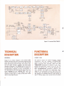
Figure
9. Functional Block
Diagram
TECHNIEAL
FUNCTIONAL
DESCRIPTION
DFSCRIPTION
GENERAL
FRONT END
diagram of the [/]odei 2245
Receiver showing the main functional elements and
input and output signal routing. Each Afl and Fß,4
front end has its own lF stages. For clarily, onlv
the leJt audio channel is shown; the right audio
channel is identical. The |\4ONO switch is common
to both chännels. All audio controls are ganged, or
con(entrically clulched, to lhplr coJnLelporls il
the righl channel. The left channel half o{ the front
Fl\4 antenna signals are applied through a balun
transformer and the antenna ATTENUATOR
switch to the antenna coil which drives a fiedeffect transistor RF amplifaer. When the ATTENUATOR pushswitch is placed in the "out"
position the attenuator circuit is cut oJf the Fivl
siqnals are direclly fed to the FIM antenna coil.
With ATTENUATOR pushswilch placed in the
"in" position, the signals are attenuated about
20dB by the attenualor circuit, then fed to the
antenna coil. The signals from the RF amplifier are
{ed through the doubl+tlned RF tank circuit to
rhe FET l\,4ixer stage, which is also fed by the signal
Fiqure
9 is a block
panel dubbing lN and dubbing OUT jacks are
shown interconnected in this diagram. The right
cl-annel of each iacl i\ wired lo lhe san_e circuit
point in the riqht channel.
11
")
generated by a local oscillator. This mixer converts
the carrier frequency to the 10.71\,4H2 intermediate
frequency. Care{ul attention to its thermal and
electrical characleristics has minimized drift, thus
obviatinq the necessity for AFC. The 107[,4H2
converted siqnal is lhen fed to a phaselinear
ceramic lF Jilter, followed by an lC limiter. lt is
then, in t.rn, processed lhrouqh dn FIVI drqcrim;na_
1or. The output of the Fl\4 discriminator is fed to a
buffer amplifier which then drives the demodula
tor,
IF
c
STAGES
The lF section consists of four traosistors and sax
ceramic filters. The characteristics o{ this filter are
ideai in thal the 200KHz passband is phase linear,
with sharp cut-of{ slopes. lts exceplional phase
lineariry ässures the ellminalion ol ä malor source
o{ high'{requency distorlion and a loss o{ stereo
separation. The sharp cutoff slopes provide im
proved selectivity, permitting reception of closely
spaced channels,
LI I\4ITE R
The l\,4odel 2245 utilizes multi-staqes (transistor
plus lam;ter diode and lC) limiter amplifier with a
very small dynamic symmetrical aperture, elirni_
nating the need for AGC circuit which introduces
low {requency distortion. Undesirable Amplitude
Modulalion (AM signals, AN,4 noise, AI\4 dislortion)
are removed frorn the 1F signal wilhin the limiter.
FIM STEREO DEIV]ODULATOR
c
The composite audio signal {rom the bLrffer amplifier is {ed inlo the multiplex stereo demodlllator
circuit consisting of 11 transistors and 6 diodes.
lhe l9lP1 pilot siqaal conldin.d in Lhe composrte
audio signal is doubled into 3BkHz after two stage
amplification and then the 3BkHz signäl is further
amplified to the level necessary to drive the diode
switchinq circuit. The composite audio signal is
split into the right änd left channeis by the 38kHz
switch;ng signal in the diode matrix circuit. The
right and left channel audio signals are processed in
the crossralk cancellinq circuit which L]tilizes com
plementary configuration with NPN and PNP
transistors. The audio signals are then {ed into the
selector switch anand the TAPE OUT jacks from
the low päss Jilters for filtering undesired 19 and
3BkHz components and enritter followers for low
impedance oulput.
The stereo demodulator circuit has been designed
with the d+emphasis net\,vork to provide flal
frequency response up to 15kHz. One hundred
percent air'tight coils and filters are incorporated
in the stereo demodulator circuit for improved
slabilitv and reliabilitv with good stereo separation
and frequencv response.
The multiplex stereo demodulator circuit has been
provided with an automalic slereo/monaural
switching circuit. The circuil checks the input
siqnal intensity and aclivates the stereo demodula
tor circuit and the stereo indicator lamp aulomatically only when the inpul signal is power{ul
enouqh 10 provide good quality stereo reception.
When the input signal strength is below the
threshold level, the FM stereo broadcast is process_
ed as monaural signal and improved signal-to_noise
rätio is obtained in this mode of operation.
IIIUTING CIRCUIT
ol dn FI\4 carrier, dll f[4 recpivers
peculiar
a
noise. The mutinq circuit
providinq
elirninates this noise,
vou with noise-free
ln
rhp dbsence
produce
tuning from slation-to station,
A muring circuil, consistinq ol a two trdnsistor
noise amplifier and a thre+transistor {including
one FET) switching circuit, has been incorporated
in the lvlodel 2245. The muring circuit perfectly
mutes out all the interstation noise and also
complptely mules oul thp side slope spurious
response of the unit. The circuil has been designed
to minimize annoying "pop" noise for velvet
smooth tune in and tune out.
AM TUN ER
The Al\4 tuner ponion of the l\,4odel 2245 has been
provided with a tuned RF ämplifier incorporaling a
three-section variable capacitor for improved
spurious response ratio,
The ceramic filter utilized in the Al\.4 lF ampliJier
comes with higher selectivity and wider bandwidth
for interference {ree hi{iAI\l reception.
Following the A[,4 lF amplif ier, tl're Al\,4 detector
recovers the audio modulation and provides this
signal to the selector switch.
The Al\4 tuner and lF amplifier are subjected to the
action of an effective aulomalic volume control
circuit which maintains constant the level of all
stations in the Al\,4 band.
SELECTOR SWITCH
Your l\,4odel 2245 has the cäpability to operate
from a variety of program sources, e.9., AM or FM
broadcasts, tlrrntable (PHoNoi, tape recorders
(TAPE) or anv other source capable of providing
IOO millivolts output level (AUX). The selector
switch connects the inputs oJ the TONE amplifiers
12
selectively to the desired source.
TAPE SIGNALS
With the exception o{ tape input, all high leve
inputs are {ed directly to the s€lector switch. Tape
input is routed through the front panel dubbing lN
jack to a section of the TAPE MONIToR switch.
The dubbinq lN jack is a three conductor stereo
jack which has two built_in switches, one for each
channel. Normally, these switches are closed,
a!lowing the tape input signals from the TAPE lN
jack on the rear panel to be fed to the TAPE
IMONITOR switch. When a plug is inserted in the
lN jack, the
switches are opened,
jacks and ällowing the
lN
TAPE
the
disconnectinq
jack
IN
to reach the TAPE
dubbing
from
the
signal
IMONITOR switch. Thus only one tape recorder at
a time can feed playback signals inlo the l\,4odel
dubbing
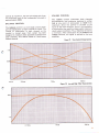
PHONO SIGNALS
Phono siqnals of up to 100 millivolts can be
handled without overloading The RIAA equal
ization nelwork provides precise equalization and
sets the voltage gain of the phono prearnplifier to
4OdB (at 1,000H2). Thls R IAA reprodLtcing charac
rerisric, IoqerhFr will I\e recordinq chaldcler'slic,
is shown in FigurelO. Notice that the net resuit
after playback is a flat response.
MONO FUNCT IONS
When the N4ONO pushswitch is in the "in"
position, the lwo channels are connected together
through mixinq resistors. ln addition, the lefl and
right channel tape input signals are connected 10
qether throLrgh a similar resistor network This
facility allows all inputs to be converted to the
2245.
monophon;c mode.
TAPE IV]ONITOR SWITCH
CONTROL CIRCUITS
When rhe TAPE MONITOR pushswitch is in the
"out" position tape input signals from the TAPE
lN jacks on the rear panel or dubbinq lN jack on
the front panel are fed to the selector switch. When
the TAPE MONITOR is depressed, the output of
the selector switch is disconnected lrom the
balance control and the tape input signais from the
TAPE lN or dubbing lN jacks feed the balance
control directlV.
The control circuits portion of the l\,'lodel 2245
consists of the balance, volume, bass, mid, treble,
Hi FILTER; and LOW FILTEB controls. All
controls affect
the left and riqht
J
channels
bass. mid and treble conlrols
simultaneouslv. The
have clutched sectlons which allow individual
adjustment of tonal balance for each channel Wilh
the controls set for flat response and volume
Fiqurel 0. Phono Equalization Characteristics
J
0dB
2AHz
l
100H2
lKHz
10K Hz
conlrol at maximum, the over all voltage gain from
any h iqh level input to the loudspeaker terminals is
approximately 40d8.
BALANCE CONTROL
The balance control is a wide range control which
oermits atLenudtion ol each channel to cutotf The
chanqe of attenuation in edch channel as the
control is turned away lrom center has been
designed to maintain total apparent loudness from
both channels. This Ieature makes it a true stereo
balance control,
c
r
VOLUME CONTROL
The volume control attenuates both channels
simultaneously and maintains tracking to within
3dB at any point of attenuation 10 50dB from
maximum. Since the control is situated at the
input of the tone amplifier, there is no possibility
of overloading lhe dmplilier stages under maximum
rated output conditions. Thus, distortion is kept to
a minimum. After atlenuation by the balance and
volume controls, the siqnal is applied to the tone
amplifier.
Figure'll. T0ne C0[trol
Characteristics
10
40Hz
IOOHz
IOKHz
lKHz
Figüre
12.
Low and High Filter Chamderistics
ffiwffi&&
wffiffiää
O.lKHz
,IKHZ
'lOKHz
14
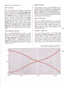
TONE AI\4PLIFIER
The TONE A[,4PL|FlER's circuitry uses a con
tinuouslv variable R-C {eedback type configura
tion. Figure 11 shows the frequency response
curves for maximum boost and cut {or each
control. The signal from the TONE A[4PLl
FIER feeds the hillow filter circuil when the
Hi FILTER or the LOW FILTER pushswilch is
depressed.
H|-LOW FILTERS
Fiqure 12 shows the {requency response curves
resulting {rom use of the two filters.
OUTPUT STAGE AND PROTECTIVE CIR.
CUITS
The pr+driver circuit ampli{ies the signal from the
Hi/LOW FILTER to sufticient levels to drive the
output stages. Beyond the input of the predriver
circuil the amplifier stages are direct'coupled
through to the loudspeakers (and headphones)
providing inslantaneous recovery from overdrive or
short circuit condilion!. ThF oLrrpul slage consists
of a pair of push p!ll, complementary symmetry
transistors (PNP, NPNI. The electronic protective
circuit senses the peak output current and limits
the current to the driver' transistors at a safe,
predetermined value. This current I imiting protects
the driver and output transistors under overdrive
and short circuit conditions and effectively
prevents the driver and output transistor from
exceeding sa{e operating conditions. This instantaneous actinq safety circuit gives constant and
unobtrusive protection wiThout causing annoying
program interruptions.
CAUTION: The loudspeaker terminals of one
channel should never be connected directly in
parallel with any other. Any resulting damage is
not covered under the warranty,
15
TECHNICAT SPECIFICATIONS
AUDIO CIRCUITS:
Rated continuous (RI\4S) power
outpul
per channel, both channels operating
.
;imultaneously, 20 Hz to 2O,OOO Hz
(lHF)
45 Watts at 4 and 8 ohms
25 Watts at 16 ohms
l35 Watts at 8 ohms
..
. .
Comparable Total l\4usic Power
High'level hum and noise (ref. 4OW at I ohms)
Phäno hum and noise .
Dynamic range {phono input to tape recordinq output)
...
. .
'1
.
l.t\4.Distortian(SIVIPTE),atratedpower.-......
Distortion decreases as output is lowered
lotal Harmonic Distortion, at rated power
Through phono
lnput Sensitivity (for 40\N at
I
80dB
pv equivalent input
96 dB
.. ....03%
'
0 3% Ivlaximum
Distortion decreases äsoutpLrt is lowered
Power Bandwidth (lH F )for 0.300 THD
Dampinq Fdctor {ref. B ohms) . .
Frequency Response
.
c
.......
5
.....
7 Hz to 70,000 Hz
Greater than 45
ohms)
.180 mV
iqh'level
Phono {1,000 Hz)
lnput lmpedance
H
1.8 mV
Hiqh-level .
Phono .. ..
Channel separation 20 Hz to 20,000
.
Hz
..
.
.
100,000 ohms
47,000 ohms
35 dB l\4inimum
Ft4 SECTIONS:
2.3
IHF Usable Sensilivily
Selectivity.
Noise Ouieting
Total Harmonic Distortion,400 Hz, 100%
lMod.
Frequency Besponse (ref.75/r sec. deemphasis)
Stereo Separdtion
.
SLrbcarrier (38 kH/) Suppression .
...
. (llono)
.. ..
.
pV
60 dB
dB
at
5!V
-55
60 dB at 10/lV
65 dB at 50 pV
0.2% (Stereo) 0.4%
11dB 50Hz to lsKHz
1,000 Hz 40 dB
60
dB
GENERALI
Power Requirements
..
-.,.,.,
At rated output, both channels oPerating
ldling Power (Volume Control at zero)
1
00 I
120/200/2201240V AC
50 to 60 Hz
310 Watts
34 Watts
Dimensions
PanelWidth
Panel Height
Depth
. ..
Weight
Unit alone
pacl ed [or <,hipnent
r
11 2l
/or
lnches
25/6r lnches
.14 lnches
34.5lbs
44.5lhs
norice
These sp€cif cations and exterior desisns mav be chansed for improvement without advance
16
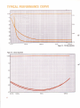
TYPICAL PEBFORMANCE CURVE
odB
ffi Wffi
ffi ffi ffi 8$$1"Wffi
W&&W*6 g$IWWffi ffi W
ffi ffi ffi ffi $twffi wffi ffi
wffi
ffi ffi
ffi ffi MS$&l:ffi ffi ffi ffi W
ffi
WRäbIWffi ffi ffi W
ffiffi MWffi
ffi Wffi
WWWR$äiWffi
$$*iWffi
Wffi ffiW$$Iiffi
MMffi $[iRMEWffi MM$&iIWffi ffi ffi ffi &$üIffi WWffi W
WWffi W ffi ffi W ffi W
Mtr Ii[M[W ffi ffi fi
ffi mFfi [iwqmwffi mtrMrwffi wmffi ü[lffi ffi wffi M
ffi
10
ffi ffi &$$iiffi
iWffi
20
30
ffi$
40
ü
Wtr H${,ffi
wffi $$11ffi
wffi ß&ttffi
ffi
HII
$fr
M&
$ [
I
50
&$IIWWW
60
\)
WffiW$I!WWW
ffiffim$fiwmffiw
70
80
100mV
100*V
Fi{üre
i3.
FIl/I CharaGteridics
figüre 14. Stereo Separatioo
0dB
ffiffi9ää$&
i.,:.i:r,;,l7^i":E
i{i;?.€;t ig!tgg
ffiKffiffä$€
ffiffiKffiffiffi*
50
1i
Hz
IOOHZ
IOKHz
J
Figure 15. Harmonic Distonion
Figure
16.
Frcqüency Besponse
+2
0 dB
2
6
-8
10
12
lOHz
IOOHz
l KHz
IOKHz
IOOKHz
18
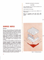
Please Pack
the Receiver as lllustrated.
CAUTION
Please DO NOT ship your receiver mounted
accessory walnut cabinet.
in its
lnsure receiver for full value:
Make sure that your correct return address is on
shipping lable.
Ship via a reputable carrier.(Do NOT UsE
PARCEL POST)Be sure to obtain receipt from
cafiier,
SERVICE NOTES
REPAIRS
Only the most competent and qualified service
technicians should be allowed to service the Marantz Model 2245 Receiver. The Marantz Company
and its warranty station personnel have the knowledge and special equipment needed for the repair
and calibration of this precision instrument.
ln the event of difficulty, write directly to the
factory (to the attention ot the technical service
department) for the name and address of the
nearest Marantz waftanty or authorized service
station. Please include the model and serial number
of the unit together with a description ol the
problem.
lf it should ever be necessary to ship the unit to
the factory or authorized seNice station and your
receiver is mounted in its accessory walnut cabinet,
ALWA.YS REMOVE IT FROM THE CABINET
BEFORE PACKING. DO NOT SHIP THE ACCESSORY WALNUT CABINET. Pack the unit careful
ly, using the original packing material. lf the
packing material has been discarded. lost, or
damaged, write to the factory {to the attention of
the technical service department) foa new packing
material. Carton, fillers, and packing instructions
will be shipped to you at a nominal charge.
No receiver should be returned to the factory
without an Authorized Return Label which the
Marantz Company will supply if the description of
difficulties appears to warrant {&tory s€rvice.
19
Fiqure
17. Packin{ lnstruclions
IIIOTE
c
c
The Sound of N4arantz
the compelling warmth o{ a Stradivarius.
It is a dancing flute, a haughty bassoon
and the plaintlve call of a one French horn.
The Sound of l\,4aranlz is the sound of beauty,
and fularantz equipment is designed to bring you
is
the subtle ioy of its delight.
Wonder{ul adventures in sound await you
when you discover that the Sound of l\,4arantz
is
the sound of music at its very best


![i36l I33l EIrIIIllIrrllIl tlrxlrllIr I lrlllr]lll It DA2](http://vs1.manualzilla.com/store/data/006759536_1-e1b2d27f25e11b765edbcc7af9879218-150x150.png)