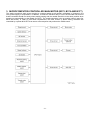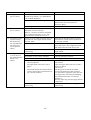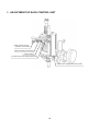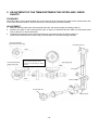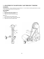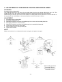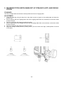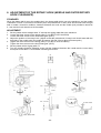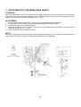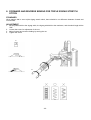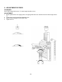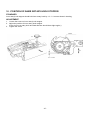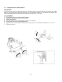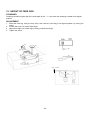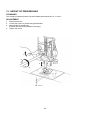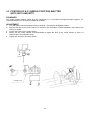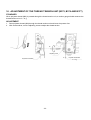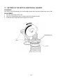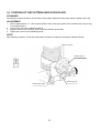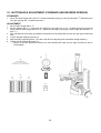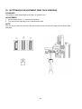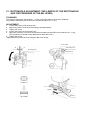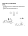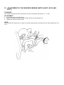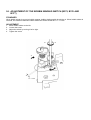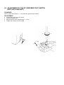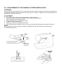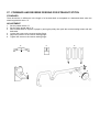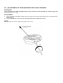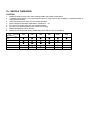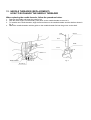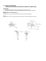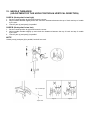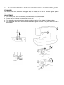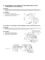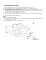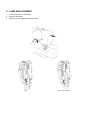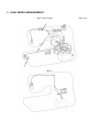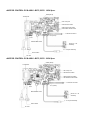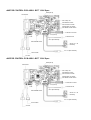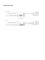
1
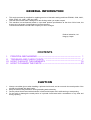
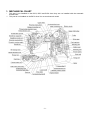
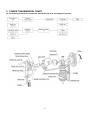
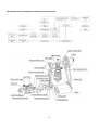
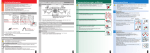
SERVICE MANUAL FOR B373 (STAR110, PS-2200)E B375 (STAR120E, PS-2300) B376 (STAR130E, PS-2400) B377 (STAR140E, PS-2500) 5. 1998. GENERAL INFORMATION · · · This service manual is complied for repairing service of domestic sewing machines PS2200, 2300, 2400 , 2500, STAR 110, 120E, 130E and 140E. Use this manual with Parts Catalogue for fault findings when you make a repair. This machine is manufactured based on up-to-date product specifications at the time of this issue, but there may be changes of specifications for improvements. Contact manufacturer or local sales company for such changes. Brother industries, Ltd. Nagoya, Japan CONTENTS I. II. III. IV. PRINCIPAL MECHANISMS ......................................................................... 1 TROUBLES AND CHECK POINTS .............................................................. 7 HOW TO ADJUST THE ELEMENTS ........................................................... 16 HOW TO CHANGE THE PARTS ................................................................. 53 CAUTION 1. 2. 3. 4. Always use rubber gloves when handling a printed circuit board, and do not touch the metal portion of the printed circuit board with bare hands. Keep the human body earthed to avoid generating static electricity. Pack a printed circuit board with aluminum foil and avoid impact with it while storing or transporting. Do not touch or damage the metal portion of a printed circuit board with a screwdriver or any other tool during repairing. I. PRINCIPAL MECHANISMS 1. 2. 3. MECHANICAL CHART ............................................................................ 2 POWER TRANSMISSION CHART .......................................................... 3 MICROCOMPUTER-CONTROLLED MAIN MOTOR (B375, B376 AND B377) .......................................................................... 6 -1- 1. MECHANICAL CHART * ** This part is not installed on the B373, B375 and B376 since they are not installed with the automatic thread cutter. This part is not installed on the B373 since it is not an electronic model. -2- 2. POWER TRANSMISSION CHART (A) Generating mechanism of needle bar, thread take-up lever and zigzag movements -3- (B) Mechanism of feed dog and oscillating hook movement -4- (C) Automatic 1-step BH mechanism -5- 3. MICROCOMPUTER-CONTROLLED MAIN MOTOR (B375, B376 AND B377) The sewing machine's main motor requires a constant rotation at all speeds, regardless of changes in the load, power supply or temperature. In addition, to make the machine easy to use, it should take into account that the machine should run slowly when starting sewing and the needle should be in the down position when stopping to automatically cut the thread (for B377). The needle should be in the up position when it stops (for B375 and B376). In order to fulfil these requirements, the main motors of these sewing machines are controlled by a power MOS FET that uses a microcomputer and performs the PWM control. -6- II. TROUBLES AND CHECK POINTS 1. 2. 3. 4. 5. 6. 7. 8. 9. 10. 11. 12. 13. 14. 15. 16. 17. 18. 19. 20. 21. 22. 23. 24. 25. Machine skips stitches. ........................................................................... 9 Fabric does not feed. .............................................................................. 9 Fabric does not feed straight. .................................................................. 9 Upper thread breaks at start. .................................................................. 9 Upper thread breaks during sewing. ....................................................... 9 Upper thread breaks during reverse sewing. .......................................... 9 Lower thread breaks. .............................................................................. 9 Needle breaks. ........................................................................................ 9 Noise. ...................................................................................................... 10 Forward and reverse feedings differ. ...................................................... 10 Improper length of buttonhole legs. ......................................................... 10 Improper buttonhole size against button size. ......................................... 10 Unbalanced patterns. .............................................................................. 10 Needle hits needle plate when pattern selector dial is turned. ................ 10 Fabric gathers. ........................................................................................ 10 The stitch shown in the pattern indication window is different from the one being sewn. ........................................................................ 10 The light does not turn on even after the power is turned on. .................. 11 The motor does not run. ........................................................................... 11 The motor does not run smoothly or it does not run at a high speed. (B375, B376 AND B377) .......................................................................... 12 Even after the machine is started, it stops suddenly. (B375, B376 AND B377) .......................................................................... 12 The speed at which the machine operates cannot be adjusted. (B375, B376 AND B377) .......................................................................... 12 The needle does not stop in the down position. (B377) The needle does not stop in the up position. (B375 AND B376) .............. 12 The machine does not operate if the reverse sewing button is pressed or does not operate at a slow speed if the button is pressed while the machine is running. (B375, B376 AND B377) ............. 13 The machine stops immediately after bobbin winding is started. (B375, B376 AND B377) .......................................................................... 13 The machine does not operate when the foot controller is depressed. (B375, B376 AND B377) ....................................................... 13 -7- The thread cutter does not operate correctly. (B377) .............................. 14 The upper and lower threads are not cut. (B377) .................................... 14 The upper thread is not cut. (B377) ......................................................... 15 The lower thread is not cut. (B377) .......................................................... 15 The machine locks up while cutting the thread. The moving blade does not return to its correct position. (B377) ......................................................... 15 31. The upper thread is removed from the needle after the thread is cut. (B377) ...................................................................................................... 15 26. 27. 28. 29. 30. -8- PROBLEM 1. Machine skips stitches. CAUSE 1. 2. 3. 4. 5. 6. 7. 8. CORRECTION Improper setting of the needle. Bent or blunt needle. Improper threading. Improper combination of needle/ thread/fabric. Stretch fabric is used. Set the needle correctly. Change the needle. Reset threading correctly. Select correct combination of needle/ thread/fabric. Use stretch fabric needle. Improper timing of the needle and rotary hook. Improper height of the needle bar. Improper clearance between the needle and rotary hook. Refer to P.23. Refer to P.24. Refer to P.23. 2. Fabric does not feed. 1. 2. 3. 4. 5. Stitch length is set at "0". Improper height of feed dog. Thick fabric. Feed dog is worn out. The feed dog is lowered. Set proper stitch length. Refer to P.29. Change the fabric. Change the feed dog. Raise the feed dog with the drop lever. 3. Fabric does not feed straight. 1. Uneven pressure on right/left side of presser foot. Change the presser foot and the feed dog. 4. Upper thread breaks at start. 1. Improper threading. Thread correctly. 5. Upper thread breaks during sewing. 1. 2. 3. 4. 5. 6. 7. 8. 9. Bent or blunt needle. Improper setting of needle. Thread tension is too tight. Thread is tangled. Inferior needle eye. Inferior needle slot of needle plate. Inferior upper thread path. Inferior thread. Needle hits needle plate or outer rotary hook. Change the needle. Set the needle correctly. Adjust tension control dial correctly. Thread correctly. Change the needle. Change the needle plate. Clean or replace. Check or change the thread. Set the needle bar and outer rotary hook correctly. * Refer to P.23. Change inner rotary hook. 10. There are scratches on inner rotary hook. 6. Upper thread breaks during reverse sewing. 1. 2. Fabric is pulled excessively. Improper use of reverse sewing button. Guide the fabric. Push reverse sewing button as far as it will allow. 7. Lower thread breaks. 1. Lower thread tension is too tight. 2. Too much thread is wound on bobbin. 3. 4. Thread is tangled. Bobbin does not turn in inner rotary hook. Inferior thread. Adjust the tension by loosening the tension spring screw on inner rotary hook. Change to other bobbin or adjust bobbin winder. Thread correctly. Change the bobbin. 5. 8. Needle breaks. 1. Touch pattern dial while needle is in the fabric. -9- Check or change the thread. Operate machine correctly. PROBLEM 8. Needle breaks. CAUSE CORRECTION 2. Needle hits inner rotary hook. 3. Needle hits needle plate. 4. 5. 7. 8. Bent or blunt needle. Improper clearance between the needle and the outer rotary hook. Machine feeds while needle is in the fabric. Needle flows. Fabric is pulled excessively. 1. 2. 3. 4. Play of worm/pattern cam gear. Play of lower shaft. Play of upper shaft. Noise from rotary hook. Adjust to proper gearing. Adjust play of the lower shaft. Adjust play of the upper shaft. Clean the race of inner rotary hook and outer rotary hook or replace inner rotary hook. 10. Forward and reverse feedings differ. 1. Improper adjustment of reverse sewing lever. Refer to P.44. 11. Improper length of buttonhole legs. 1. Improper adjustment. Adjust screw. * Refer to P.36. 12. Improper buttonhole size against button size. 1. Improper adjustment of buttonhole length. Adjust the length of buttonhole. * Refer to P.38. 13. Unbalanced patterns. 1. 2. Stitch length dial is not set at ''SS''. Feed dog is worn out. 3. 4. 5. 6. Improper height of feed dog. Improper attachment of feed dog. Forward and reverse feedings differ. Stitch width dial is not set to "5". Operate machine correctly. Change the feed dog. * Refer to P.28, P.29. Refer to P.29. Attach the feed dog correctly. Refer to P.25. Operate machine correctly. 14. Needle hits needle plate when pattern selector dial is turned. 1. Release volume is too big. Adjust the release volume. * Refer to P.22. 15. Fabric gathers. 1. 2. 3. 4. Thread tension is too tight. Blunt needle. Improper combination of needle/ thread/fabric. Improper threading. Reduce the tension. Change the needle. Select correct combination of needle/ thread/fabric. Reset threading correctly. 1. Release volume is too small. 2. The indicate gear and pattern indicator plate are not aligned correctly. Adjust the release volume. * Refer to P.22. Adjust the pattern indicator. * Refer to P.35. 6. 9. Noise. 16. The stitch shown in the pattern indication window is different from the one being sewn. - 10 - Adjust the position of inner rotary hook stopper. * Refer to P.27. Make sure the correct needle is used. * Refer to P.21, P.22. Change needle. Refer to P.23. Refer to P.19. Refer to P.21. Guide the fabric. PROBLEM 17. The light does not turn on even after the power is turned on. (B375, B376 and B377) CAUSE 1. Replace either the AC cord or the motor control unit. 6. The voltage on both ends of connector SOURSE is not 120V or 230V AC when the AC cord is inserted. The resistance on both ends of the power switch is not less than 1 W when the power is turned on.* The fuse is broken. The light does not turn on. (The light may be damaged or deteriorating or it may have a bad connection.) Remove the light and measure the resistance on both ends. It should be less than 30 W.* The output from the transformer is incorrect. When connector CN1 is disconnected from the motor control unit and the power is turned on, the voltage between pins 1 and 2 of connector CN1 should be approximately 13 V AC. Other causes. 1. Inferior light bulb. Replace the light bulb. *Refer to P.55. 1. The pulley is turned too tightly. 2. 6. 7. The resistance between the two ends of motor connector MOTOR is not between 30 and 40 W (120V), 120 and 130 W (230V).* Inferior SS switch. The resistance between pins 3 and 4 of the SS-VR PCB assy. connector should be less than 1 W when the SS switch is turned on and ¥ when the SS switch is turned off.* Inferior BT switch. The resistance between pins 1 and 2 of connector CN3 (red) should be less than 1 W when the BT switch is turned on and ¥ when the BT switch is turned off.* The resistance between pins 1 and 2 of the pin jack assembly on the PCB (F.C.) should not be less than 1 W when the foot controller is not inserted.* The fuse is broken. Other causes. Adjust the mechanism so that the pulley rotates easily. Replace the motor. 1. 2. Inferior foot controller. Inferior motor or inferior brush. 2. 3. 4. 5. Light is off. (B373) 18. The motor does not run. (B375, B376 and B377) 3. 4. 5. Motor does not run. (B373) CORRECTION Replace the motor control unit. Replace the fuse or the motor control unit. Replace the light. Replace the motor control unit. Replace the motor control unit. Replace the SS-VR PCB assy.. Replace the BT switch. *Refer to P.40. Replace the motor control unit. Replace the fuse or the motor control unit. Replace the motor control unit. Replace the foot controller. Replace the motor. * Be sure to turn off the power and remove the connector from the PCB. - 11 - PROBLEM 19. The motor does not run smoothly or it does not run at a high speed. (B375, B376 and B377) CAUSE 1. 2. 3. 4. 5. 6. 7. 8. 20. Even after the machine is started, it stops suddenly. (B375, B376 and B377) 1. 21. The speed at which the machine operates cannot be adjusted. (B375, B376 and B377) 1. 2. 2. 3. 4. 22. The needle does not stop in the down position. (B377) The needle does not stop in the up position. (B376 and B375) 1. 2. 3. 4. CORRECTION The pulley is sometimes easy or sometimes difficult to move when it is rotated by hand. Accumulated lint or thread under the needle plate. Improper tension in motor belt and timing belt. Tight gearing of the pattern cam gear and worm gear. The rotary shutter is dirty. The motor control unit is installed incorrectly. It is loose or slanted. The voltage between pins 2Å and 4 on the SS-VR PCB does not stay between 0 and 5 V DC when the power is turned on and the speed adjustor is slid to the maximum. Other causes. Adjust the mechanism so that the pulley rotates easily. The motor control unit is installed incorrectly. It is loose or slanted. Other causes. Install the motor control unit correctly. The output from the transformer is incorrect. The voltage between pins 10 and 12 of the transformer should be approximately 12 V AC. The voltage between the 5 V and GND on the motor control unit is incorrect. It should be 5± 0.25 V DC. The voltage between pins 2Å and 4 on the SS-VR PCB does not stay between 0 and 5 V DC when the power is turned on and the speed adjustor is slid to the maximum. Other causes. Replace the motor control unit. The position of the NP sensor shutter is incorrect. The motor control unit is installed incorrectly. It is loose or slanted. Inferior BW switch. The resistance between pins 1 and 2 of connector CN7 (black) should be less than 1 W when the BW switch is turned on and ¥ when the BW switch is turned off.* Other causes. Check and adjust if necessary. *Refer to P.31. Install the motor control unit correctly. Clean inner rotary hook, outer rotary hook and feed dog. Refer to P.20. Refer to P.21. Clean the rotary shutter. Install the motor control unit correctly. Replace the SS-VR PCB unit. Replace the motor control unit. Replace the motor control unit. Replace the motor control unit. Replace the SS-VR PCB unit. Replace the motor control unit. Replace the BW switch. *Refer to P.41. Replace the motor control unit. * Be sure to turn off the power and remove the connector from the PCB. - 12 - PROBLEM 23. The machine does not operate if the reverse sewing button is pressed or does not operate at a slow speed if the button is pressed while the machine is running. (However, the machine does not operate at slow speed when the foot controller is being used.) (B375, B376 and B377) 24. The machine stops immediately after bobbin winding is started. (B375, B376 and B377) CAUSE 1. The BT switch does not work. 2. Inferior BT switch. The resistance between pins 1 and 2 of connector CN3 (red) should be less than 1 W when the BT switch is turned on and ¥ when the BT switch is turned off.* Other causes. 3. 1. 2. 25. The machine does not operate when the foot controller is depressed. (B375, B376 and B377) CORRECTION 1. 2. 3. Check and adjust if necessary. *Refer to P.40. Replace the BT switch. *Refer to P.40. Replace the motor control unit. If the machine stops approximately. 1 second after bobbin winding starts, the BW switch is not operating correctly. The resistance between pins 1 and 2 of connector CN7 (black) should be less than 1 W when the BW switch is turned on and ¥ when the BW switch is turned off. * Other causes. Replace the BW switch. *Refer to P.41. The foot controller is not operating properly. The resistance between the two ends of the foot controller plug is not less than 10 KW.* The resistance between pins 1 and 2 of the pin jack assembly on the PCB (F.C.) should be less than 1 W when the foot controller is plugged in and ¥ when it is not plugged in.* Other causes. Replace the foot controller. Replace the motor control unit. Replace the motor control unit. Replace the motor control unit * Be sure to turn off the power and remove the connector from the PCB. - 13 - PROBLEM 26. The thread cutter does not operate correctly. (B377) 1. 2. 3. 4. 5. 6. 27. The upper and lower threads are not cut. CAUSE The thread cutter solenoid lever does not move easily. The resistance between pins 1 and 2 of the thread cutter solenoid connector (J12) is not between 15 and 19 W.* The thread cutter switch is not operating. The thread cutter switch is not operating properly. The resistance between pins 1 and 2 of connector CN4 (blue) should be less than 1 W when the switch is turned on and ¥ when the switch is turned off.* The voltage of the motor control PCB solenoid is not approximately DC 30V. Other causes. The thread cutter cam is out of phase. 1. 2. 3. 4. 5. 1. CORRECTION Check and adjust if necessary. 2. Replace the thread cutter solenoid. 3. Check and adjust if necessary. 4. Replace the thread cutter switch. 5. Replace the motor control unit. 6. Replace the motor control unit. Check that the thread cutter cam (lower shaft assembly) and the outer rotary hook are correctly in phase. Refer to P.19. The moving blade does not operate correctly The thread cutter solenoid connector is Connect the connector. disconnected. Refer to P.56. The thread cutter solenoid does not Check that the thread cutter solenoid operate correctly. assembly is correctly installed. The thread cutter cam does not engage Check that the thread cutter assembly is with the pin correctly. correctly installed. If it is installed correctly, replace it or the lower shaft. Refer to P.52. Thread is tangled. Remove the needle plate and the free-arm cover, then remove any caught thread and clean the thread cutter assembly and rotary hook. Other parts are causing interference. Check that the thread cutter assembly and all surrounding parts are correctly installed. The thread cutter switch connector is disconnected. Connect the connector. Refer to P.56. The thread cutter switch is incorrectly adjusted. Adjust it to the correct position. Refer to P.43. The machine is not being operated correctly 1. 2. 3. 4. The thread cutter operation lever is not fully lowered. The presser foot is not lowered. The needle is above the needle plate. The bobbin winding shaft is moved to the right (the position for winding the bobbin). Fully lower the thread cutter operation lever. Lower the presser foot. Turn the pulley until the needle is in the down position. Move the bobbin winding shaft to the left. * Be sure to turn off the power and remove the connector from the PCB. - 14 - PROBLEM 28. The upper thread is not cut. (B377) CAUSE CORRECTION The machine skips stitches. (Refer to"1. Machine skips stitches. "in" TROUBLES AND CHECK POINTS".) Refer to the related items. The thread cutter cam is out of phase. Check that the thread cutter cam (lower shaft) and the outer rotary hook are correctly in phase. The moving and fixed blades are not sharp. Replace with new blades. 29. The lower thread is not cut. (B377) The thread is not cut because the moving blade does not move correctly. (Refer to 3, 4 and 5 of "The moving blade does not operate correctly." of "27. The upper and lower threads are not cut.") Refer to the related items. 30. The machine locks up while cutting the thread. The moving blade does not return to its correct position. (B377) Stitches are sewn while the tension discs are open and a lot of the upper thread remains under the fabric. Check that the thread tension disc and the thread tension control release mechanisms are correctly installed. Thread is tangled. Remove the needle plate and the free-arm cover, then remove any caught thread and clean the thread cutter and rotary hook. The thread cutting operation was performed while sewing. Follow the procedure for removing any caught thread. 31. The upper thread is removed from the needle after the thread is cut. (B377) The spool is not installed correctly. Correctly install the spool of thread. The machine is not correctly threaded. Correctly thread the machine. Tension is applied while cutting the thread 1. The thread cutter switch is not correctly adjusted. The upper shaft notch cam is out of phase. The thread tension disc and the thread tension control release mechanisms are not correctly installed. Correctly adjust the thread cutter switch. Refer to P.43. Adjust the upper shaft notch cam so that is correctly in phase. Refer to P.51. With the power turned off, the needle lowered, and the thread cutter operation lever operated to engage the notch, pass the thread (polyester #30) along the threading path and check that there is no tension applied to it. Correctly adjust any parts that apply tension to the thread. The thread cutting operation was performed while sewing. Do not perform the thread cutting operation while sewing. 2. 3. - 15 - III. HOW TO ADJUST THE ELEMENTS 1. ADJUSTMENT OF EACH CONTROL UNIT ............................................ 18 2. ADJUSTMENT OF THE TIMING BETWEEN THE UPPER AND LOWER SHAFTS ..................................................................................... 19 3. ADJUSTMENT OF THE MOTOR BELT AND TIMING BELT TENSIONS ....................................................................... 20 4. ADJUSTMENT OF THE NEEDLE POSITION AND NEEDLE SWING ..... 21 5. MAXIMUM STITCH WIDTH WHEN SET AT STRAIGHT (LEFT) AND ZIGZAG STITCH ...................................................................................... 22 6. ADJUSTMENT OF THE ROTARY HOOK (NEEDLE AND OUTER ROTARY HOOK CLEARANCE) ........................ 23 7. ADJUSTMENT OF THE NEEDLE BAR HEIGHT ..................................... 24 8. FORWARD AND REVERSE SEWING FOR TRIPLE ZIGZAG STRETCH STITCH .................................................................................. 25 9. ADJUSTMENT OF FEED ......................................................................... 26 10. POSITION OF INNER ROTARY HOOK STOPPER ................................ 27 11. POSITION OF FEED DOG ...................................................................... 28 12. HEIGHT OF FEED DOG .......................................................................... 29 13. HEIGHT OF PRESSER BAR ................................................................... 30 14. POSITION OF N.P. (NEEDLE POSITION) SHUTTER (B375, B376 AND B377) .......................................................................... 31 15. ADJUSTMENT OF THE THREAD TENSION DIAL ................................. 32 16. ADJUSTMENT OF THE THREAD TENSION UNIT (B375, B376 AND B377) .......................................................................... 33 17. SETTING OF THE STITCH LENGTH DIAL HOLDER ............................. 34 18. POSITION OF THE PATTERN INDICATION PLATE .............................. 35 19. BUTTONHOLE ADJUSTMENT (FORWARD AND REVERSE FEEDING) ................................................................................................ 36 20. BUTTONHOLE ADJUSTMENT (BAR TACK FEEDING).......................... 37 21. BUTTONHOLE ADJUSTMENT (THE LENGTH OF THE BUTTONHOLE AND THE PRESSURE OF THE BH LEVER) ................. 38 22. ADJUSTMENT OF THE BOBBIN WINDING ............................................ 39 23. ADJUSTMENT OF THE REVERSE SEWING SWITCH (B375, B376 AND B377) .......................................................................... 40 - 16 - 24. ADJUSTMENT OF THE BOBBIN WINDING SWITCH (B375, B376 AND B377) .......................................................................... 41 25. ADJUSTMENT OF THE PF (PRESSER FOOT) SWITCH (B375, B376 AND B377) .......................................................................... 42 26. ADJUSTMENT OF THE THREAD CUTTER SWITCH (B377) ................. 43 27. FORWARD AND REVERSE FEEDING FOR STRAIGHT STITCH .......... 44 28. ADJUSTMENT OF THE INNER ROTARY HOOK TENSION ................... 45 29. NEEDLE THREADER .............................................................................. 46 30. NEEDLE THREADER (CHECKING THE HOOK POSITION IN HORIZONTAL DIRECTION) .................................................................... 47 31. NEEDLE THREADER (REPLACEMENT) HOW TO EXCHANGE THE NEEDLE THREADER ................................. 48 32. NEEDLE THREADER (CHECKING THE HOOK POSITION IN VERTICAL DIRECTION) ......... 49 33. NEEDLE THREADER (ADJUSTMENT OF THE HOOK POSITION IN VERTICAL DIRECTION) ... 50 34. ADJUSTMENT OF THE THREAD CUTTER NOTCH CAM POSITION (B377) ...................................................................................................... 51 35. ADJUSTMENT OF THE THREAD CUTTER FRAME INSTALLATION POSITION ...................................................................... 52 - 17 - 1. ADJUSTMENT OF EACH CONTROL UNIT 2. Back and forth seam at automatic reverse pattern 5. Bar tack feeding at buttonhole 3. Forward feeding 4. Forward and reverse feeding at buttonhole 1. Adjustment for straight stitch at left position - 18 - 2. ADJUSTMENT OF THE TIMING BETWEEN THE UPPER AND LOWER SHAFTS STANDARD When the mark on the horizontal feed cam of the upper shaft is horizontal, the mark on the thread cutter cam of the lower shaft should be 5° above horizontal. (Turn the pulley counterclockwise.) ADJUSTMENT 1. 2. 3. Remove the timing belt from the horizontal feed cam, the tension pulley and timing pulley D. Position the mark on the horizontal feed cam so that it is horizontal and the mark on the thread cutter cam so that it is 5° above horizontal. Install the timing belt onto the horizontal feed cam, the tension pulley and timing pulley D. (At this time, the mark on the outer rotary hook should be in the center facing forward.) Upper shaft assembly (horizontal feed cam pulley) Horizontal feed cam Mark Lower shaft assembly (thread cutter cam) When the mark on the horizontal feed cam is horizontal, the mark on the thread cutter cam should be 5° above horizontal. Outer rotary hook Mark Timing belt 5° Mark Tension pulley Thread cutter cam Timing pulley D - 19 - 3. ADJUSTMENT OF THE MOTOR BELT AND TIMING BELT TENSIONS STANDARD There should be 4 ~ 6 mm of slack on the motor belt and 3 ~ 4 mm of slack on the timing belt when the center of each belt is pushed with about 200 g pressure. ADJUSTMENT Timing belt 1. Loosen the screw on the tension pulley. 2. Adjust the tension pulley position. 3. Tighten the screw on the tension pulley. Motor belt 1. Loosen the two motor holder screws. 2. Move the motor holder to adjust the belt slack. 3. Tighten the two motor holder screws. 3 ~ 4 mm 4 ~ 6 mm 200g 200g - 20 - 4. ADJUSTMENT OF THE NEEDLE POSITION AND NEEDLE SWING STANDARD Set pattern dial to zigzag stitch. The needle should drop in the center of the needle plate hole when the zigzag width dial is set to "0". The needle should drop in the needle hole balanced when the zigzag width dial is set to the maximum. Needle swing on the way up from the lowest position to needle plate should be less than 0.15 mm and that on the way down from needle plate to the lowest position should be less than 0.05 mm. ADJUSTMENT 1. 2. 3. 4. 5. 6. 7. 8. Set pattern dial to zigzag stitch. Set zigzag width dial to "0". Adjust the eccentric nut so that the needle drops in the center of the needle plate hole. Set zigzag width dial to "the maximum". Adjust the eccentric nut so that the needle drops in the needle hole balanced. Loosen three set screws on worm gear. Adjust needle swing by turning worm gear. Tighten three screws. NOTE Make sure that there is no clearance between worm gear and pattern cam gear. Adjusting range When needle goes down .... less than 0.05 mm When needle comes up .... less than 0.15 mm - 21 - 5. MAXIMUM STITCH WIDTH WHEN SET AT STRAIGHT (LEFT) AND ZIGZAG STITCH STANDARD Left end of straight stitch should be the same position as left end of zigzag stitch. ADJUSTMENT 1. 2. 3. 4. 5. 6. Lower the feed dog using the drop lever, then place a piece of paper on the needle plate and lower the presser foot. Set the pattern dial to the zigzag stitch and set the zigzag width dial to the maximum so that the needle moves to the left. Drop the needle into the paper by turning the pulley. Set the pattern dial to the straight stitch and set the zigzag width dial to the maximum so that the needle moves to the left. Drop the needle into the paper by turning the pulley. Adjust left straight needle position by turning screw. (Turn the screw to the right, needle position is moved to the right.) - 22 - 6. ADJUSTMENT OF THE ROTARY HOOK (NEEDLE AND OUTER ROTARY HOOK CLEARANCE) STANDARD When the pattern dial is set to the straight stitch, the zigzag width dial is set to the maximum, and the needle is between 2.8 and 3.2 mm above its lowest point, the pointed end of rotary hook should meet with the right side of needle. Under this condition, clearance between the hook and the needle (#14) should be less than 0.1 mm and the hook should not hit the needle. ADJUSTMENT 1. 2. 3. 4. 5. 6. Set the pattern dial to straight stitch "2" and set the zigzag width dial to the maximum. Loosen the three screws on the timing pulley D. (for B373, B375 and B376) Loosen the three screws on the lower shaft gear. (B377) Adjust the position of the rotary hook. (Adjust so that the pointed end of rotary hook should meet with the right side of the needle when the needle is between 2.8 and 3.2 mm above its lowest point.) Tighten the three screws on the timing pulley D. (for B373, B375 and B376) Tighten the three screws on the lower shaft gear. (B377) Set the pattern dial to zigzag stitch "3". Turn the needle clearance adjusting screw until the clearance between the needle and the outer rotary hook point is less than 0.1 mm without contacting each other. 2.8 ~ 3.2 mm B377 0 mm 0.1 mm or less 2.8 ~ 3.2 mm 0.1 mm or less B373, B375, B376 - 23 - 7. ADJUSTMENT OF THE NEEDLE BAR HEIGHT STANDARD When the pattern dial is set to the straight stitch, the zigzag width dial is set to the maximum and the pointed end of the rotary hook contacts the right side of the needle, the distance from the top of the needle eye to the bottom of the outer rotary hook point should be 0.9 ~ 1.3 mm. ADJUSTMENT 1. 2. 3. 4. 5. Set the pattern dial to straight stitch "2" and set the zigzag width dial to the maximum. Turn the pulley until the rotary hook point meets with the right side of the needle. Loosen the screw on the needle bar clamp. Adjust the needle bar until the distance from the top of the needle eye to the bottom of the outer rotary hook point should be 0.9 ~ 1.3 mm. Tighten the screw on the needle bar clamp. NOTE Since the needle bar can easily be rotated while adjusting the height of the needle bar, causing problems while sewing, be careful to keep the needle clamp parallel with the needle plate. Needle bar clamp 0.9 ~ 1.3 mm Needle clamp - 24 - 0 mm 8. FORWARD AND REVERSE SEWING FOR TRIPLE ZIGZAG STRETCH STITCH STANDARD When pattern dial is set to triple zigzag stretch stitch, there should be no difference between forward and reverse feed. ADJUSTMENT 1. 2. 3. 4. Set the pattern dial to the zigzag stitch, the zigzag width dial to the maximum, and the stitch length dial to "SS". Loosen the screw for adjustment of the nut. Adjust forward and reverse feeding by turning the nut. Tighten the screw. - 25 - 9. ADJUSTMENT OF FEED STANDARD When stitch length dial is set to "0", stitch length should be 0 mm. ADJUSTMENT 1. 2. 3. 4. Set the pattern dial to the zigzag stitch, the zigzag width dial to the maximum and the stitch length dial to "0". Loosen the nut for forward feed adjusting screw. Adjust forward feeding by turning the screw. Tighten the nut. - 26 - 10. POSITION OF INNER ROTARY HOOK STOPPER STANDARD Inner rotary hook stopper should hold inner rotary hook by 1.9 ~ 2.1 mm as shown in drawing. ADJUSTMENT 1. 2. 3. Loosen the screw on inner rotary hook stopper. Adjust the position of inner rotary hook stopper. (Face A on inner rotary hook and feed direction should be at right angles.) Tighten the screw. Face A 1.9 ~ 2.1 mm - 27 - 11. POSITION OF FEED DOG STANDARD When the upper shaft is rotated once with the maximum feed, the feed dog should not contact the needle plate on the left and right. When the feed dog is in its initial feed position (as far forward as possible), the clearances between the feed dog and the needle plate should be 0.3 ~ 0.8 mm. ADJUSTMENT 1. 2. 3. 4. 5. 6. 7. Loosen two screws on the horizontal feed plate. Adjust the left and right sides of the feed dog. Tighten two screws. Turn the pulley to move the feed dog to its initial feed position. Loosen the screw on the horizontal feed arm. Adjust the arm so the clearance between the feed dog and the needle plate is between 0.3 ~ 0.8 mm. Tighten the screw. Initial feed dog position 0.3 ~ 0.8 mm - 28 - 12. HEIGHT OF FEED DOG STANDARD Feed dog should be higher than the needle plate by 0.9 ~ 1.1 mm when the feed dog is raised to its highest position. ADJUSTMENT 1. 2. 3. 4. Raise the feed dog using the drop lever, then raise the feed dog to its highest position by turning the pulley. Loosen the screw for vertical feed finger. Adjust the height of the feed dog by turning vertical feed finger. Tighten the screw. 0.9 ~ 1.1 mm - 29 - 13. HEIGHT OF PRESSER BAR STANDARD The clearance between presser foot and needle plate should be 6.0 ~ 6.5 mm. ADJUSTMENT 1. 2. 3. 4. Raise presser foot. Loosen the screw on presser bar guide bracket. Adjust height of presser bar. (Presser foot should be parallel to feed dog.) Tighten the screw. 6.0 ~ 6.5 mm - 30 - 14. POSITION OF N.P. (NEEDLE POSITION) SHUTTER (B375, B376 AND B377) STANDARD The needle position shutter works when the needle bar is 1.9 mm below its highest position (approx. 37° counterclockwise from the topmost needle bar position). ADJUSTMENT 1. 2. 3. 4. 5. Turn the pulley counterclockwise until the needle is 1.9 mm below its highest position. Remove the two screws on the sensor PC board of the controller PC board assembly, then remove the sensor PC board. Loosen the screw on the rotary shutter. Slowly turn the rotary shutter counterclockwise to adjust the face of the center shutter so that it is centered slit of the insulation cover. Tighten the screw on the rotary shutter. 1.9 mm Insulation cover - 31 - 15. ADJUSTMENT OF THE THREAD TENSION DIAL STANDARD When thread tension dial is set to "4" and presser foot is lowered, upper thread tension should be 33 ~ 38g using polyester thread #60. ADJUSTMENT 1. 2. 3. 4. Set thread tension dial to "4", put polyester thread between tension discs and lower presser foot. Loosen the screw for thread tension control screw. Measure thread tension using tension gauge and adjust tension to 33 ~ 38g by turning thread tension control screw. Tighten the screw. - 32 - 33 ~ 38 g Polyester thread # 60 16. ADJUSTMENT OF THE THREAD TENSION UNIT (B375, B376 AND B377) STANDARD When polyester thread (#60) is passed through the thread tension unit, a tension gauge should measure the thread tension to be 8 ~ 12 g. ADJUSTMENT 1. 2. Pass polyester thread (#60) through the thread tension unit and lower the presser foot. With a screwdriver, turn the adjusting screw to adjust the thread tension. Adjusting screw Polyester thread #60 - 33 - Polyester thread #60 8 ~ 12 g 17. SETTING OF THE STITCH LENGTH DIAL HOLDER STANDARD The mark on the feed adjusting cam faces straight forward when the stitch length dial is set to "SS". ADJUSTMENT 1. 2. 3. Turn the stitch length dial to "SS". Adjust the feed adjusting cam so that its mark faces straight forward. Install the stitch length dial holder using the two screws. Feed adjusting cam Screw Mark - 34 - 18. POSITION OF THE PATTERN INDICATION PLATE STANDARD Each pattern number should be in the center of the pattern indicator window each time the pattern dial is set. ADJUSTMENT 1. 2. 3. 4. Set the pattern dial to "3". (The second position when turning the pattern dial clockwise after fully turning it counterclockwise.) Loosen the screw on the indication gear B. Align the holes in the indication gear A and the indication gear holder. Tighten the screw on the indication gear B. NOTE After selecting a pattern, check that each pattern number is centered in the pattern indicator window. Reference position Indication gear A Indication gear B Indication gear holder - 35 - 19. BUTTONHOLE ADJUSTMENT (FORWARD AND REVERSE FEEDING) STANDARD 1. When the stitch length dial is set to "F" during buttonhole sewing, the left leg should be from the right leg (50 ~ 60 stitches/20 mm). +10 0 stitches/20 mm ADJUSTMENT 1. 2. 3. 4. 5. 6. Set the stitch length dial to "F". Set the pattern dial to "1" and check the stitching of the right leg. (If 50 ~ 60 stitches/20 mm cannot be sewn with the stitch length dial set to "F", adjust the stitching by moving the stitch length dial between "F" and "1".) Sew a buttonhole and check the difference between the left backward bar tack and the right forward bar tack. Loosen the BHF adjusting screw nut. Adjust the BHF adjusting screw. (The slit in the BH fine-adjusting knob should be straight upward.) Tighten the BHF adjusting screw nut. * Adjust so that the difference between the left backward bar tack and the right forward bar tack is unnoticeable. - 36 - 20. BUTTONHOLE ADJUSTMENT (BAR TACK FEEDING) STANDARD The feeding of a bar tack should be less than 10 stitches/1 mm. ADJUSTMENT 1. 2. Set the pattern dial to "1", then sew a buttonhole. Turn the bar tack adjusting screw to adjust the bar tack. NOTE Turn the screw to the left to move the bar tack forward; turn the screw to the right to move the bar tack backward. - 37 - 21. BUTTONHOLE ADJUSTMENT (THE LENGTH OF THE BUTTONHOLE AND THE PRESSURE OF THE BH LEVER) STANDARD The length of buttonhole should be 21 ~ 23 mm, when the button is 20.0 mm in diameter. The pressure needed to pull the BH lever forward should be 50 ~ 110 g. ADJUSTMENT 1. 2. 3. 4. 5. Loosen the screw on BH change arm. Adjust the position of BH lever according to drawings below. Tighten the screw. Loosen the screw for the eccentric nut. Adjust the eccentric nut so that the pressure needed to pull the BH lever forward is 50 ~ 110 g. (The eccentric nut should not be rotated more than half a turn.) 6. Tighten the screw. *Adjust the timing of the BH lever using the BH notch screw. Screw BH notch screw BH change arm Eccentric nut 20mm 50 ~ 110 g Shorter 21 ~ 23 mm - 38 - Longer BH lever 22. ADJUSTMENT OF THE BOBBIN WINDING STANDARD Thread should be wound parallel to the bobbin and be wound 75 ~ 85% of the outer-diameter of bobbin. ADJUSTMENT 1. 2. 3. 4. 5. 6. In case bobbin thread is wound unbalanced, loosen the screw for bobbin winder thread guide slightly. Move bobbin winder thread guide vertically so that the bobbin thread is balanced when it is wound. Tighten the screw. Loosen the screw for the bobbin presser slightly. Move the bobbin presser to adjust the amount of thread wound on it. Tighten the screw. 75 ~ 85 % - 39 - 23. ADJUSTMENT OF THE REVERSE SEWING SWITCH (B375, B376 AND B377) STANDARD The clearance between the BT switch and the reverse sewing lever should be 1.0 ~ 1.5 mm. ADJUSTMENT 1. 2. 3. Loosen the screw on the BT switch. Adjust the clearance between the BT switch and the reverse sewing lever. Tighten the screw on the BT switch. NOTE Check that the BT switch turns on when the reverse sewing button is pressed and the stitch length dial is set to "0". 1.0 ~ 1.5 mm - 40 - 24. ADJUSTMENT OF THE BOBBIN WINDING SWITCH (B375, B376 AND B377) STANDARD When bobbin winder is moved to bobbin presser, bobbin winding switch should be on. When bobbin winder is returned, the clearance between bobbin winder and switch should be 1.0 ~ 1.5 mm. ADJUSTMENT 1. 2. 3. 4. Move bobbin winder to the left. Loosen the screw. Adjust the switch by moving it left to right. Tighten the screw. 1.0 ~ 1.5 mm - 41 - 25. ADJUSTMENT OF THE PF (PRESSER FOOT) SWITCH (B375, B376 AND B377) STANDARD The PF switch should bend 1 ~ 2 mm when the presser foot is raised. ADJUSTMENT 1. 2. 3. 4. Loosen the screw on the PF switch. Raise the presser foot. Adjust so that the PF switch bends 1 ~ 2 mm. Tighten the screw on the PF switch. 1 ~ 2 mm - 42 - 26. ADJUSTMENT OF THE THREAD CUTTER SWITCH (B377) STANDARD When the thread cutter operation lever is operated while the needle is lowered and the latch is engaged, the thread cutter switch should go on between the point where the latch is engaged and the position where the thread cutter operation lever stops. ADJUSTMENT 1. 2. 3. 4. 5. 6. Turn off the power, then turn the pulley until the needle is lowered. Press down on the thread cutter operation lever to the position where the latch is engaged, then release the lever. Loosen the screw on the thread cutter switch. Position the thread cutter switch. Tighten the screw on the thread cutter switch. Turn the thread cutter operation lever even more and check that the thread cutter switch is turned on. NOTE When the pulley is turned to raise the needle to its highest position, the thread cutter operation lever automatically resets itself. Normal position Latch engaging position The thread cutter switch should be on all through this range. Thread cutter operation lever stop position - 43 - 27. FORWARD AND REVERSE FEEDING FOR STRAIGHT STITCH STANDARD There should be no difference in the length of a forward stitch as compared to a backward stitch when the stitch length dial is set to "2". ADJUSTMENT 1. 2. 3. 4. 5. 6. Set the pattern dial to "2". Set the stitch length dial to "2". Sew forward stitch on a piece of paper by turning the pulley then push the reverse sewing button and sew backward. Loosen the screw on the reverse sewing finger. Adjust the position of the reverse sewing finger. Tighten the screw on the reverse sewing finger. - 44 - 28. ADJUSTMENT OF THE INNER ROTARY HOOK TENSION STANDARD When polyester thread (#60) threaded through the inner rotary hook is slowly pulled with a tension gauge, the tension should be 10 ~ 12 g. ADJUSTMENT 1. 2. Using polyester thread (#60), thread the inner rotary hook as usual, then slowly pull on the thread with a tension gauge. Using a screwdriver, turn the tension spring adjusting screw to adjust the tension. NOTE After adjusting the tension, apply locking paint to the screw. Polyester thread #60 10 ~ 12 g - 45 - 29. NEEDLE THREADER CAUTION 1. 2. 3. 4. 5. 6. 7. 8. Needle threader accepts only circle marked needle and thread combinations. * marked combinations is not recommended since it might lead to the breakage of needle threader or imperfect performance. Lower the presser foot when you use needle threader. Nylon transparent thread is applicable in needle #14 ~ 16. Do not turn the pulley when you use needle threader. Do not touch needle threader when machine is running. Needle #9 might be hard to thread. Needle should be located above needle plate more than 8.0 mm for threading. Thread #30 #50 #60 #80 #100 #120 #9 5 5 5 ¡ ¡ ¡ #11 5 ¡ ¡ ¡ ¡ * #14 5 ¡ ¡ ¡ * * #16 * ¡ ¡ * * * #18 * * * * * * Needle - 46 - 30. NEEDLE THREADER (CHECKING THE HOOK POSITION IN HORIZONTAL DIRECTION) STANDARD The measure from inside of the hook guard to the center point of hook is 0.42 mm. CHECK Prepare 5 pcs. of brand-new sewing HA´1 (#14) and check by changing all of these. After Checking A. In case that, hook gets through eyelet of all needles...........................Nothing is the matter. B. In case that, hook does not get through eyelet of all needles..............Adjust by bending hook. C. In case that, hook does not get through eyelet of some needles.........Needles through which the hook does not get, are bad. ADJUSTMENT In case the hook is bad after above checking, adjust the hook by forming with pliers. In this case, do not form hook guard. - 47 - 31. NEEDLE THREADER (REPLACEMENT) HOW TO EXCHANGE THE NEEDLE THREADER When replacing the needle threader, follow the procedure below. 1. 2. 3. 4. Remove the needle and lower the presser foot. With the index fingers of both hands, push down on the needle threader to remove it. To install a new needle threader, align the flat surfaces on the needle threader and the shaft as shown in fig. A. Attach the needle threader until the guide on the needle threader fits into the groove on the shaft. shaft Groove D cut Guide D cut Fig. A Take out Needle threader Push up - 48 - 32. NEEDLE THREADER (CHECKING THE HOOK POSITION IN VERTICAL DIRECTION) STANDARD 1. 2. The clearance between the top of hook and the top of needle eye is zero. Threading is capable when needle is located higher than 9.0 mm from the needle plate. CHECK (Refer to the illustration.) Case A Hook position is too high. (Hook hits needle and cannot get through needle eye.) Case B Hook position is too low. (Hook gets through needle eye but it catches bottom part of needle.) Needle Needle Top of needle eye 0 mm Top of hook Hook Needle Fig. A Fig. B - 49 - 33. NEEDLE THREADER (ADJUSTMENT OF THE HOOK POSITION IN VERTICAL DIRECTION) CASE A (Hook point is too high) 1. 2. 3. Set the needle position at right and loosen the screw. Adjust needle threader slightly down and check the clearance between the top of hook and top of needle eye is zero. Check if part (a) and part (b) is parallel . CASE B (Hook point is too low) 1. 2. 3. Set the needle position at right and loosen the screw. Adjust needle threader slightly up and check the clearance between the top of hook and top of needle eye is zero. Check if part (a) and part (b) is parallel. NOTE Unless part (a) and part (b) is parallel, hook will not work. (a) (b) Top of needle eye 0 mm Fig. A Top of hook - 50 - Fig. B 34. ADJUSTMENT OF THE THREAD CUTTER NOTCH CAM POSITION (B377) STANDARD The thread cutter latch should be disengaged when the needle bar is 1.6 mm below its highest position (approx. 34° counterclockwise from the topmost needle bar position). ADJUSTMENT 1. 2. 3. 4. 5. Turn off the power, then turn the pulley counterclockwise to lower the needle. Press down on the thread cutter operation lever until the latch is engaged. Loosen the two screws on the thread cutter notch cam. Turn the pulley counterclockwise to raise the needle so that it is 1.6 mm below its highest position. Turn the thread cutter notch cam counterclockwise, then tighten the screw at the point where the notch is disengaged. 1.6 mm - 51 - 35. ADJUSTMENT OF THE THREAD CUTTER FRAME INSTALLATION POSITION (B373, B375 AND B376) STANDARD 1. 2. The thread cutter frame should be positioned so that there is no space between it and the side of the arm. It should be positioned so that the space between the thread cutter frame and the outer rotary hook is 1.9 ~ 2.2 mm. ADJUSTMENT 1. 2. 3. Loosen the two mounting screws. Position the thread cutter frame assembly. Tighten the two mounting screws. 0 mm Screw 0 mm Screw 1.9 ~ 2.2 mm ADJUSTMENT OF THE THREAD CUTTER ASSEMBLY INSTALLATION POSITION (B377) STANDARD 1. 2. The thread cutter assembly should be positioned so that there is no space between it and the side of the arm. The space between the thread cutter cam end and the pin should be 1.7 ~ 1.9 mm. ADJUSTMENT 1. 2. 3. Loosen the two mounting screws. Position the thread cutter assembly. Tighten the two mounting screws. 0 mm Screw Install so that there is no space in the front and back between the thread cutter frame and the side of the arm. 0 mm Screw Pin Pin Thread cutter cam Install so that the space between the thread cutter cam end and the pin is 1.7 ~ 1.9 mm 1.7 ~ 1.9 mm Thread cutter cam - 52 - IV. HOW TO CHANGE THE PARTS 1. REMOVING THE COVERS ..................................................................... 54 2. LAMP REPLACEMENT ............................................................................ 55 3. LEAD WIRES ARRANGEMENT .............................................................. 56 <MAIN PCB ASSY> ........................................................................................ 57 - 53 - 1. REMOVING THE COVERS 1. 2. 3. 4. 5. 6. 7. Remove the face plate screw, then remove the face plate by pulling it off to the left. Remove the free-arm cover screw, then remove the free-arm cover by pulling it off to the left. Pull the thread cutter operation lever off toward you. Loosen the two front cover screws (at the bottom corner near the face plate and at the bottom of the free arm), then lift the front cover toward you from the bottom, disconnect the connector, remove the front cover and pull the reverse sewing button off toward you. Pull the switch cover off to the right from the top of the cover. Lower the presser foot lever, remove the three rear cover screws, and pull the rear cover off toward the rear. Pull the BH adjustment knob off to the right. NOTE INSTALLING THE FRONT COVER A. Set the pattern dial to the zigzag stitch (The second position when turning the pattern dial clockwise after fully turning it counterclockwise.). B. Set the pattern on the front cover to the zigzag stitch "3". B B375, B376 and B377 - 54 - 2. LAMP REPLACEMENT 1. 2. 3. Loosen the screw of face plate. Remove face plate. Attach new sew-light bulb to lamp socket B373 B375, B376 AND B377 - 55 - 3. LEAD WIRES ARRANGEMENT (B377, B375, B376) * * * (B373) - 56 - * B377 only <MOTOR CONTROL PCB ASSY> B375, B376 120V Spec. GND (JW18) Transformer CN1 Lamp unit CN3 Reverse switch CN6 Presser foot switch CN7 Bobbin winder switch To SS-VR connector +5 V (JW15) Fuse MOTOR Main motor Sensor P. C. B. assembly F. C. Pin jack assembly Power switch AC Inlet <MOTOR CONTROL PCB ASSY> B375, B376 230V Spec GND (JW18) Transformer CN1 Lamp unit CN3 Reverse switch CN6 Presser foot switch CN7 Bobbin winder switch To SS-VR connector +5 V (JW15) Fuse MOTOR Main motor Sensor P. C. B. assembly F. C. Pin jack assembly Power switch AC Inlet - 57 - <MOTOR CONTROL PCB ASSY> B377 120V Spec. GND (JW18) Transformer CN1 Lamp unit CN3 Reverse switch CN4 Thread cut switch CN6 Presser foot switch CN7 Bobbin winder switch To SS-VR connector +5 V (JW15) Fuse To Solenoid unit +30 V (D5 Cathode) MOTOR Main motor Sensor P. C. B. assembly F. C. Pin jack assembly Power switch AC inlet <MOTOR CONTROL PCB ASSY> B377 230V Spec. GND (JW18) Transformer CN1 Lamp unit CN3 Reverse switch CN4 Thread cut switch CN6 Presser foot switch CN7 Bobbin winder switch To SS-VR connector +5 V (JW15) Fuse To Solenoid unit +30 V (D5 Cathode) MOTOR Main motor Sensor P. C. B. assembly F. C. Pin jack assembly Power switch AC inlet - 58 - <SS-VR PCB ASSY> (B375, B376) Speed Volume (B377) - 59 - - 38 - B373 (STAR110, PS-2200) B375 (STAR120E, PS-2300) B376 (STAR130E, PS-2400) B377 (STAR140E, PS-2500) T7110099